EP1634062B1 - Readhead for optical inspection apparatus - Google Patents
Readhead for optical inspection apparatusDownload PDFInfo
- Publication number
- EP1634062B1 EP1634062B1EP04754753.4AEP04754753AEP1634062B1EP 1634062 B1EP1634062 B1EP 1634062B1EP 04754753 AEP04754753 AEP 04754753AEP 1634062 B1EP1634062 B1EP 1634062B1
- Authority
- EP
- European Patent Office
- Prior art keywords
- light
- light source
- readhead
- sample carrier
- chamber
- Prior art date
- Legal status (The legal status is an assumption and is not a legal conclusion. Google has not performed a legal analysis and makes no representation as to the accuracy of the status listed.)
- Expired - Lifetime
Links
- 238000007689inspectionMethods0.000titledescription15
- 230000003287optical effectEffects0.000titledescription9
- 230000005284excitationEffects0.000claimsdescription31
- 238000005286illuminationMethods0.000claimsdescription31
- WQZGKKKJIJFFOK-GASJEMHNSA-NGlucoseNatural productsOC[C@H]1OC(O)[C@H](O)[C@@H](O)[C@@H]1OWQZGKKKJIJFFOK-GASJEMHNSA-N0.000claimsdescription13
- 239000008103glucoseSubstances0.000claimsdescription13
- 238000000034methodMethods0.000claimsdescription6
- 239000011888foilSubstances0.000claimsdescription4
- 229910052751metalInorganic materials0.000claimsdescription4
- 239000002184metalSubstances0.000claimsdescription4
- 239000011521glassSubstances0.000claimsdescription2
- 230000008569processEffects0.000claimsdescription2
- 239000010453quartzSubstances0.000claimsdescription2
- VYPSYNLAJGMNEJ-UHFFFAOYSA-Nsilicon dioxideInorganic materialsO=[Si]=OVYPSYNLAJGMNEJ-UHFFFAOYSA-N0.000claimsdescription2
- 230000000704physical effectEffects0.000claims3
- 238000012360testing methodMethods0.000abstractdescription18
- 239000003153chemical reaction reagentSubstances0.000description42
- 210000002700urineAnatomy0.000description22
- 210000001124body fluidAnatomy0.000description16
- 239000010839body fluidSubstances0.000description16
- 238000001055reflectance spectroscopyMethods0.000description11
- 210000004369bloodAnatomy0.000description9
- 239000008280bloodSubstances0.000description9
- 238000001506fluorescence spectroscopyMethods0.000description7
- 239000007788liquidSubstances0.000description7
- 239000012491analyteSubstances0.000description5
- 238000003018immunoassayMethods0.000description5
- 150000001875compoundsChemical class0.000description4
- 239000004033plasticSubstances0.000description4
- 210000000265leukocyteAnatomy0.000description3
- 230000004044responseEffects0.000description3
- 238000002835absorbanceMethods0.000description2
- 230000003466anti-cipated effectEffects0.000description2
- 235000013405beerNutrition0.000description2
- 230000008859changeEffects0.000description2
- 238000013461designMethods0.000description2
- 238000005516engineering processMethods0.000description2
- 239000012530fluidSubstances0.000description2
- 239000000463materialSubstances0.000description2
- 238000012544monitoring processMethods0.000description2
- 239000000758substrateSubstances0.000description2
- XLYOFNOQVPJJNP-UHFFFAOYSA-NwaterSubstancesOXLYOFNOQVPJJNP-UHFFFAOYSA-N0.000description2
- 238000001069Raman spectroscopyMethods0.000description1
- 239000002250absorbentSubstances0.000description1
- 230000002745absorbentEffects0.000description1
- NIXOWILDQLNWCW-UHFFFAOYSA-Nacrylic acid groupChemical groupC(C=C)(=O)ONIXOWILDQLNWCW-UHFFFAOYSA-N0.000description1
- 230000003213activating effectEffects0.000description1
- 230000004913activationEffects0.000description1
- 230000015556catabolic processEffects0.000description1
- 238000006243chemical reactionMethods0.000description1
- 239000011248coating agentSubstances0.000description1
- 238000000576coating methodMethods0.000description1
- 239000000470constituentSubstances0.000description1
- 238000006731degradation reactionMethods0.000description1
- 210000003743erythrocyteAnatomy0.000description1
- 230000001747exhibiting effectEffects0.000description1
- 238000002839fiber optic waveguideMethods0.000description1
- 238000001917fluorescence detectionMethods0.000description1
- 239000007850fluorescent dyeSubstances0.000description1
- 239000007789gasSubstances0.000description1
- 238000002347injectionMethods0.000description1
- 239000007924injectionSubstances0.000description1
- 150000002484inorganic compoundsChemical class0.000description1
- 229910010272inorganic materialInorganic materials0.000description1
- 238000012986modificationMethods0.000description1
- 230000004048modificationEffects0.000description1
- 150000002894organic compoundsChemical class0.000description1
- 239000002245particleSubstances0.000description1
- 239000004417polycarbonateSubstances0.000description1
- 229920000515polycarbonatePolymers0.000description1
- 238000009597pregnancy testMethods0.000description1
- 230000005855radiationEffects0.000description1
- 229910052709silverInorganic materials0.000description1
- 239000004332silverSubstances0.000description1
- 239000007787solidSubstances0.000description1
- 238000004611spectroscopical analysisMethods0.000description1
- 239000000126substanceSubstances0.000description1
- 238000002562urinalysisMethods0.000description1
- 230000000007visual effectEffects0.000description1
Images

Classifications
- G—PHYSICS
- G01—MEASURING; TESTING
- G01N—INVESTIGATING OR ANALYSING MATERIALS BY DETERMINING THEIR CHEMICAL OR PHYSICAL PROPERTIES
- G01N21/00—Investigating or analysing materials by the use of optical means, i.e. using sub-millimetre waves, infrared, visible or ultraviolet light
- G01N21/17—Systems in which incident light is modified in accordance with the properties of the material investigated
- G01N21/25—Colour; Spectral properties, i.e. comparison of effect of material on the light at two or more different wavelengths or wavelength bands
- G01N21/251—Colorimeters; Construction thereof
- G—PHYSICS
- G01—MEASURING; TESTING
- G01N—INVESTIGATING OR ANALYSING MATERIALS BY DETERMINING THEIR CHEMICAL OR PHYSICAL PROPERTIES
- G01N21/00—Investigating or analysing materials by the use of optical means, i.e. using sub-millimetre waves, infrared, visible or ultraviolet light
- G01N21/84—Systems specially adapted for particular applications
- G01N21/8483—Investigating reagent band
- G—PHYSICS
- G01—MEASURING; TESTING
- G01N—INVESTIGATING OR ANALYSING MATERIALS BY DETERMINING THEIR CHEMICAL OR PHYSICAL PROPERTIES
- G01N21/00—Investigating or analysing materials by the use of optical means, i.e. using sub-millimetre waves, infrared, visible or ultraviolet light
- G01N21/62—Systems in which the material investigated is excited whereby it emits light or causes a change in wavelength of the incident light
- G01N21/63—Systems in which the material investigated is excited whereby it emits light or causes a change in wavelength of the incident light optically excited
- G01N21/64—Fluorescence; Phosphorescence
Definitions
- the present disclosurerelates to an apparatus and method for optically inspecting a sample of body fluid and, more particularly, to a readhead for use with the apparatus. Even more particularly, the present disclosure relates to a readhead including components for conducting both fluorescence and reflectance spectroscopy.
- spectroscopyuses the linear relationship between absorbance and concentration of an absorbing species (Beer's law), to determine the contents of a sample.
- An unknown concentration of an analytecan be determined by measuring the amount of light that a sample absorbs and applying Beer's law. If the absorptivity coefficient of the analyte is not known, the unknown concentration can be determined using a working curve of absorbance versus concentration derived from standards.
- immunoassayis a technology for identifying and quantifying organic and inorganic compounds.
- Immunoassayuses antibodies that have been developed to bind with a target compound or class of compounds. The technology has been used widely because the antibodies can be highly specific to the target compound or group of compounds and because immunoassay kits are relatively quick and simple to use.
- Concentrations of analytesare identified through the use of a sensitive colorimetric reaction. The determination of the target analyte's presence is made by comparing the color developed by a sample of unknown concentration with the color formed by the standard containing the analyte at a known concentration. The concentration of the analyte is determined by the intensity of color in the sample. The concentration can be estimated roughly by the naked eye or can be determined more accurately with a reflectance spectroscope.
- Reflectance spectroscopyis the study of light as a function of wavelength that has been reflected or scattered from a solid, liquid, or gas.
- a conventional reflectance spectroscopemay determine the color of a liquid sample, such as urine or blood, disposed on a white, non-reactive pad by illuminating the pad and taking a number of reflectance readings from the pad, each having a magnitude relating to a different wavelength of visible light. The color of the sample on the pad may then be determined based upon the relative magnitudes of red, green, blue and infrared reflectance signals.
- Reagent padscan be provided with different reagents which cause a color change in response to the presence of a certain type of constituent in urine, such as leukocytes (white blood cells) or red blood cells.
- a reagent stripmay have ten or more different types of reagent pads, for example. Immunoassay strips or cassettes may also be used with other types of liquid samples, such as blood.
- U.S. Patent No. 5,654,803which is assigned to the assignee of the present disclosure, discloses an apparatus and method for determination of non-hemolyzed levels of occult blood in urine using reflectance spectroscopy.
- the apparatusis provided with a light source for successively illuminating a plurality of different portions of a reagent pad on which a urine sample is disposed, and a detector array for detecting light received from the reagent pad and generating a plurality of reflectance signals in response to light received from a corresponding one of the different portions of the reagent pad.
- the apparatusis also provided with means for determining whether the magnitude of one of the reflectance signals is substantially different than the magnitude of another of the reflectance signals. Where the body-fluid sample is urine, this capability allows the apparatus to detect the presence of non-hemolyzed levels of occult blood in the urine sample.
- U.S. Patent No. 5,877,863which is also assigned to the assignee of the present disclosure, shows an optical inspection apparatus for inspecting a liquid sample, such as urine, using reflectance spectroscopy.
- the apparatusincludes a readhead for illuminating a target area substantially uniformly via only a single light-emitting diode for each wavelength of interest arid receiving light from the target area so that reagent tests may be performed.
- the readheadis provided with a housing, first and second light sources mounted in a fixed position relative to the housing, a light guide mounted to receive light from each of the light sources which conveys, when only one of the light sources is illuminated, substantially all of the light from the light source to illuminate a target area substantially uniformly, and a light detector coupled to receive light from the target area.
- Each of the first and second light sourcesis composed of only a single light-emitting diode for emitting substantially monochromatic light of a different wavelength.
- Fluorescence spectroscopyis the study of light that has been absorbed at one wavelength and re-emitted at a different wavelength (e.g., fluorescent light is re-emitted by a sample of body fluid in response to a light having a specific wavelength, such as ultraviolet light, being directed at the sample). It is useful for various medical diagnostic purposes to use fluorescence detection to analyze samples of body fluid, for example, to determine a level of glucose in a patient's blood or urine, or to determine a pH level of the patient's blood or urine.
- U.S. Patent No. 6,232,609 to Snyder et al.shows an apparatus for glucose monitoring.
- the glucose monitorilluminates a sample with water with ultraviolet excitation light that induces the water and any glucose present in the sample to emit return light that includes Raman scattered light and glucose emission or fluorescence light.
- the return lightis monitored and processed using a predictive regression model to determine the concentration of glucose in the sample.
- the predictive regression modelaccounts for nonlinearities between the glucose concentration and intensity of return light within different wavelength bands at a predetermined excitation light energy or the intensity of return light within a predetermined wavelength band at different excitation energy levels.
- a fiber-optic waveguideis used to guide the excitation light from a laser excitation source to the sample and the return light from the sample to a sensor.
- the readheadwill include components for conducting both fluorescence spectropy and reflectance spectroscopy.
- the disclosureis directed to exemplary embodiments of a new and improved readhead for a diagnostic instrument for illuminating a sample carrier (e.g., a strip or cassette having a liquid sample) and receiving light from the sample carrier, and that allows both fluorescence spectroscopy and reflectance spectroscopy to be conducted in a simple and convenient manner.
- a sample carriere.g., a strip or cassette having a liquid sample
- One exemplary embodiment of the readheadincludes a housing adapted to be incorporated in the diagnostic instrument and including an illumination chamber for receiving a sample carrier, an array of light sources mounted within the housing in a fixed position relative to the illumination chamber, and including a first light-emitting diode for emitting substantially monochromatic light of a first wavelength and a second light-emitting diode for emitting substantially monochromatic light of a second wavelength substantially different from the first wavelength, a light guide mounted in the housing to receive light from each of the light-emitting diodes, for conveying, when only one of the light-emitting diodes is illuminated, substantially all of the light from the one light-emitting diode to the illumination chamber so that the illumination chamber is illuminated substantially uniformly, and a light detector coupled to receive light from the illumination chamber.
- These components of the readheadallow reflectance spectroscopy to be conducted on a fluid sample.
- the readheadalso includes a fluorescence excitation light source for directing excitation light of a predetermined wavelength to the illumination chamber, and a light filter positioned between the illumination chamber and the light detector and adapted to prevent passage therethrough of the excitation light from the fluorescence excitation light source but allow passage of emissive light from a sample carrier in the illumination chamber having a wavelength different from the predetermined wavelength of the excitation light.
- a fluorescence excitation light sourcefor directing excitation light of a predetermined wavelength to the illumination chamber
- a light filterpositioned between the illumination chamber and the light detector and adapted to prevent passage therethrough of the excitation light from the fluorescence excitation light source but allow passage of emissive light from a sample carrier in the illumination chamber having a wavelength different from the predetermined wavelength of the excitation light.
- the present inventionrelates to a readhead for a diagnostic instrument according to claims 1, 2 or 3.
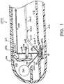
- FIG. 1shows an exemplary embodiment of a new and improved readhead 200 constructed in accordance with the present disclosure for use as part of an apparatus for optically inspecting samples of body fluid for medical diagnostic purposes.
- the read head of FIG. 1is adapted to perform both fluorescence spectroscopy and reflectance spectroscopy on a body fluid sample.
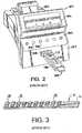
- FIG. 2illustrates a reflectance spectroscope 100, for optically inspecting liquid samples such as body fluid samples.
- the particular apparatus 100 shown in FIG. 2is a CLINITEK® 50 Urine Chemistry Analyzer available from Bayer Corporation, Diagnostics Division, of Tarrytown, NY.
- the apparatus 100is described in greater detail in U.S. Patent Nos. 5,654,803 ; 5,877,863 ; and 5,945,341 .
- the exemplary inspection apparatus 100 shown in FIG. 2has an integral keyboard 102 for user input, and a visual display 106 for displaying various messages to a user relating to the operation of the inspection apparatus 100.
- the inspection apparatus 100also has a housing 107 with an opening 108 formed therein into which a support tray 120 may be retracted. As shown in FIG. 2 , the support tray 120 is adapted to receive a first type of liquid sample carrier or removable insert, which may be in the form of a reagent cassette 122.
- the reagent cassette 122may be a disposable, single-use cassette for doing a pregnancy test, for example, in a conventional manner.
- the reagent cassette 122has an opening or well 124 into which a body fluid sample, such as urine, is placed.
- the interior of the reagent cassette 122has a reagent strip (not shown) which may react with the body fluid sample placed in the well 124.
- the reagent stripmay change color (e.g., a colored stripe may appear), which is determinable from viewing the reagent strip through a window 128 of the reagent cassette 122.
- the support tray 120may have a calibration chip of a certain color, such as white, disposed in its upper surface to facilitate calibration.
- a new and improved readhead according to the present disclosurecan also be used with a lateral flow immunoassay using a fluorescent particle as a label.
- a reagent strip 40may have a thin, non-reactive substrate 41 on which a number of reagent pads 50 are fixed.
- Each reagent pad 50may be composed of a relatively absorbent material impregnated with a respective reagent, each reagent and reagent pad 50 being associated with a particular test to be performed.
- urinalysis teststhey may include, for example, a test for leukocytes in the urine, a test of the pH of the urine, a test for blood in the urine, etc.
- the reagent strip 40may be, for example, a MULTISTIX® reagent strip commercially available from Bayer Corporation, Diagnostics Division, of Tarrytown, NY.
- the support tray 120is moved between an outwardly extended position as shown in FIG. 2 and an optical inspection position in which the tray 120 is retracted inwardly into the housing 107 of the inspection apparatus 100 and into a readhead contained in the housing.
- FIGS. 4 and 5show an exemplary embodiment of a readhead 10 of the inspection apparatus 100.
- the readhead 10has a housing formed from an upper housing portion 12, a middle housing portion 14, and a lower housing portion 16 which maybe connected together in any conventional manner.
- the housing portions 12, 14, 16may be injection-molded parts comprising black plastic to substantially absorb any errant light rays that are incident upon the housing.
- LEDs 20Light sources in the form of light-emitting diodes (LEDs) 20 are supported on a ledge 22 formed in the lower housing portion 16. Each of the LEDs 20 is designed to emit monochromatic radiation of a different wavelength, corresponding to red light, green light, blue light and infrared. The wavelength of the light emitted may vary from about 400 nanometers (for blue light) to about 1,000 nanometers (for infrared). Each of the LEDs 20 may be selectively turned on and off via a plurality of wires 24 connected between the LEDs 20 and an activation circuit (not shown). The readhead 10 may be provided with additional LEDs providing additional wavelengths.
- the CLINITEK STATUS® Urine Chemistry Analyzerincludes six LEDs, while the CLINITEK® 50 Urine Chemistry Analyzer includes four LEDs.
- the LEDs 20are disposed directly adjacent and in very close proximity with an inlet end 26a of a light guide 26 into which light from the LEDs 20 is radiated.
- the light guide 26has a relatively long, substantially planar portion 26b and a portion 26c that curves downwardly towards an outlet end 26d of the light guide 26.
- FIG. 4which is a top cross-sectional view of a portion of the readhead 10, the light guide 26 has a pair of curved sides 26e, 26f that diverge outwardly from the inlet end 26a to the outlet end 26d of the light guide 26.
- the light guide 26which may be an injection-molded part composed of clear plastic such as acrylic or polycarbonate, conducts substantially all light that enters its inlet end 26a to its outlet end 26d via total internal reflection.
- the exterior of the light guide 26could optionally be coated with a highly reflective coating, such as silver.
- the light guide 26is supported within the lower housing portion 16 by a pair of supports 28 disposed beneath the light guide 26 at a point near its inlet end 26a and a plurality of supports 30 disposed beneath the light guide 26 at a point near its outlet end 26d.
- the supports 28, 30may be integrally formed with the lower housing portion 16. As shown in FIG. 4 , the light guide 26 is positioned between a pair of angled guide walls 32, 34.
- the support 42is nonmovable relative to the housing portions 12, 14, 16.
- Light from the reagent strip 40passes through a rectangular opening 54 formed in the lower housing portion 16, in a direction indicated by an arrow 56, towards a mirror element 58 fixed in the upper left corner of the upper housing portion 12.
- the mirror element 58is composed of a cylindrical mirror 60 and a pair of mounting tabs 62 connected to the mirror 60.
- the mirror element 58which may be a plastic injection molded part having the curved portion 60 being coated with a highly reflective material, extends approximately the length of the aperture 54 shown in FIG.
- the CLINITEK STATUS® Urine Chemistry Analyzerincludes a flat mirror.
- the mirror 60reflects light that is incident upon it from the reagent strip 40 through a square aperture 64 formed in the middle housing portion 14 and to a lens 66 supported by the middle housing portion 14, as indicated by an arrow 68.
- One side of the lens 66has a planar surface and the other side of the lens 66 has a convexly curved (aspheric) surface.
- Light passing through the lens 66is transmitted to a light detector array 70, as indicated by an arrow 72.
- the detector array 70which is fixed to a side wall 74 of the upper housing portion 12, may comprise a conventional detector array, such as a TSL 1402 commercially available from Texas Instruments, which is composed of 256 individual light detectors aligned in a single horizontal row, or a Sony ILX511, a 2048 detector array, which is used in the CLINITEK STATUS® Urine Chemistry Analyzer includes.
- a conventional detector arraysuch as a TSL 1402 commercially available from Texas Instruments, which is composed of 256 individual light detectors aligned in a single horizontal row, or a Sony ILX511, a 2048 detector array, which is used in the CLINITEK STATUS® Urine Chemistry Analyzer includes.
- each individual light detector in the array 70senses light from a particular point along the length of the reagent strip 40. For example, to detect light from the lowermost reagent pad 50, a number of the light detectors on the corresponding end of the detector array 70 would be activated. Light from all of the reagent pads 50 could be simultaneously detected by activating all of the detectors in the array 70.
- the cross-sectional shape of the mirror 60is curved so that each light detector in the detector array 70 detects light from a wider portion of the reagent strip 40 than if a mirror having a straight cross-sectional shape were used.
- a straight mirrorcould be used instead of the cylindrically curved mirror 60.
- the mirror element 58could be omitted, and the detectors 70 could be placed directly above the aperture 54.
- the light guide 26is diverging, having a relatively small width at its inlet end 26a and a relatively large width at its outlet end 26d.
- the fact that the light guide 26 is divergingacts to 1) spread the light from a single one of the LEDs 20 along a relatively large length, corresponding to the length of the outlet end 26d, and 2) cause the light rays emitted by one of the LEDs 20 to be randomized, thus providing more uniform illumination at the target area in which the reagent strip 40 is located, by causing some of the light rays to be internally reflected within the light guide 26 at different angles.
- a single light raymay be reflected from the walls at different angles (i.e. at successively shallower angles of incidence with respect to the side walls as the light ray passes from the inlet to the outlet), thus increasing the randomness of the light rays and the uniformity of the illumination.
- the LEDs 20comprise lensless LEDs, such as surface-mount LEDs.
- Conventional LEDsare typically provided with a lens which covers the light-emitting component of the LED, however, a lensless LED acts more of a Lambertian source by exhibiting a much lower degree of directionality.
- FIG. 6illustrates the structure of the conventional lensless LEDs 20. Referring to FIG. 6 , each LED 20 is shown to generally comprise a substrate 80 having a cavity 82 formed therein, with the light-emitting structure 84 being disposed within the cavity 82 and with no lens covering the cavity 82 or the light-emitting structure 84.
- the present inventionprovides a new and improved readhead 200 for use as part of an apparatus (such as the apparatus 100 of FIG. 2 ) for optically inspecting samples of body fluid for medical diagnostic purposes.
- the read head 200 of FIG. 1is similar to the readhead 10 of FIGS. 4 and 5 such that similar elements have the same reference numeral preceded by a "2".
- the read head 200 of FIG. 1however is adapted to perform fluorescence spectroscopy, in addition to reflectance spectroscopy, on a body fluid sample.
- the readhead 200also includes LEDs, a lens and a detector array, similar to the readhead 10 of FIGS. 4 and 5 .
- the readhead 200 of FIG. 1further includes an ultraviolet light source chamber 300 containing an ultraviolet light source 302 and having an opening 304 for directing light from the ultraviolet light source 302 into the illumination chamber 244 of the readhead 200.
- the interior of the chamber 300may be lined with metal foil 306 to protect the plastic walls of the chamber from ultraviolet light degradation.
- the readhead 200also includes an ultraviolet filter 308 in the light path 256 to prevent an excitation wavelength of the light source 302 from being detected by the detector array, so that the detector array will only detect an emission wavelength produced by the pads 50 of the reagent strip 40.
- ultraviolet excitation light from the light source 302is directed against the pads 50 of the reagent strip 40, as illustrated by arrow 310. Emission light from the pads 50 of the reagent strip 40 then travels through the ultraviolet filter 308 in the light path 256, is reflected off the mirror 260 and directed along the light path 268 to the detector array. Determining the wavelength and intensity of emissive light received by the detector array can be used to determine properties of the sample being excited with the light source 302. For instance, the wavelength and intensity of emissive light can be used to determine the amount of glucose in a blood sample.
- U.S. Patent No. 6,232,609 to Snyder et al.shows an apparatus for glucose monitoring that uses ultraviolet excitation and monitors the wavelength and intensity of emissive light to monitor glucose levels.
- the detector arraymonitors the return light and generates electrical signals indicative of the intensity of return light associated with glucose concentration distinguishing characteristics of the emission light.
- a processor connected to the detector arrayprocesses the electrical signals, using a predictive model, to determine the concentration of glucose in the sample. Suitable examples of predictive models are shown in U.S. Patent No. 6,232,609 to Snyder et al.
- the light source 302comprises a black fluorescent lamp having a line output at 364 nanometers, 405 nanometers, and 436 nanometers, and a broadband output from 330-385 nanometers.
- the light sourcemay comprise an ultraviolet LED positioned in the ultraviolet light source chamber 300 or adjacent to the other LEDs 20 at the input end of the light guide 26.
- the ultraviolet LEDmay have an output of 370 nanometers or 400 nanometers, for example.
- the light guide 26 for an ultraviolet LEDis made of glass or quartz.
- a high intensity green LEDcan be used to trigger fluorescence, and can be used with suitable filters. It should be anticipated that future LEDs will cover a wider range of UV wavelengths and that more fluorescent dyes or markers will also be developed.
Landscapes
- Life Sciences & Earth Sciences (AREA)
- Physics & Mathematics (AREA)
- Health & Medical Sciences (AREA)
- General Physics & Mathematics (AREA)
- Pathology (AREA)
- Analytical Chemistry (AREA)
- Biochemistry (AREA)
- General Health & Medical Sciences (AREA)
- Chemical & Material Sciences (AREA)
- Immunology (AREA)
- Spectroscopy & Molecular Physics (AREA)
- Molecular Biology (AREA)
- Investigating Or Analysing Materials By Optical Means (AREA)
- Investigating Or Analysing Biological Materials (AREA)
- Investigating, Analyzing Materials By Fluorescence Or Luminescence (AREA)
- Investigating Or Analysing Materials By The Use Of Chemical Reactions (AREA)
- Automatic Analysis And Handling Materials Therefor (AREA)
Abstract
Description
- The present disclosure relates to an apparatus and method for optically inspecting a sample of body fluid and, more particularly, to a readhead for use with the apparatus. Even more particularly, the present disclosure relates to a readhead including components for conducting both fluorescence and reflectance spectroscopy.
- It is useful for various medical diagnostic purposes to utilize a reflectance spectroscope to analyze samples of body fluid, for example, to determine the color of a person's urine or blood. As is known, spectroscopy uses the linear relationship between absorbance and concentration of an absorbing species (Beer's law), to determine the contents of a sample. An unknown concentration of an analyte can be determined by measuring the amount of light that a sample absorbs and applying Beer's law. If the absorptivity coefficient of the analyte is not known, the unknown concentration can be determined using a working curve of absorbance versus concentration derived from standards.
- For example, immunoassay is a technology for identifying and quantifying organic and inorganic compounds. Immunoassay uses antibodies that have been developed to bind with a target compound or class of compounds. The technology has been used widely because the antibodies can be highly specific to the target compound or group of compounds and because immunoassay kits are relatively quick and simple to use. Concentrations of analytes are identified through the use of a sensitive colorimetric reaction. The determination of the target analyte's presence is made by comparing the color developed by a sample of unknown concentration with the color formed by the standard containing the analyte at a known concentration. The concentration of the analyte is determined by the intensity of color in the sample. The concentration can be estimated roughly by the naked eye or can be determined more accurately with a reflectance spectroscope.
- Reflectance spectroscopy is the study of light as a function of wavelength that has been reflected or scattered from a solid, liquid, or gas. A conventional reflectance spectroscope may determine the color of a liquid sample, such as urine or blood, disposed on a white, non-reactive pad by illuminating the pad and taking a number of reflectance readings from the pad, each having a magnitude relating to a different wavelength of visible light. The color of the sample on the pad may then be determined based upon the relative magnitudes of red, green, blue and infrared reflectance signals. Reagent pads can be provided with different reagents which cause a color change in response to the presence of a certain type of constituent in urine, such as leukocytes (white blood cells) or red blood cells. A reagent strip may have ten or more different types of reagent pads, for example. Immunoassay strips or cassettes may also be used with other types of liquid samples, such as blood.
U.S. Patent No. 5,654,803 , which is assigned to the assignee of the present disclosure, discloses an apparatus and method for determination of non-hemolyzed levels of occult blood in urine using reflectance spectroscopy. The apparatus is provided with a light source for successively illuminating a plurality of different portions of a reagent pad on which a urine sample is disposed, and a detector array for detecting light received from the reagent pad and generating a plurality of reflectance signals in response to light received from a corresponding one of the different portions of the reagent pad. The apparatus is also provided with means for determining whether the magnitude of one of the reflectance signals is substantially different than the magnitude of another of the reflectance signals. Where the body-fluid sample is urine, this capability allows the apparatus to detect the presence of non-hemolyzed levels of occult blood in the urine sample.U.S. Patent No. 5,877,863 , which is also assigned to the assignee of the present disclosure, shows an optical inspection apparatus for inspecting a liquid sample, such as urine, using reflectance spectroscopy. The apparatus includes a readhead for illuminating a target area substantially uniformly via only a single light-emitting diode for each wavelength of interest arid receiving light from the target area so that reagent tests may be performed. The readhead is provided with a housing, first and second light sources mounted in a fixed position relative to the housing, a light guide mounted to receive light from each of the light sources which conveys, when only one of the light sources is illuminated, substantially all of the light from the light source to illuminate a target area substantially uniformly, and a light detector coupled to receive light from the target area. Each of the first and second light sources is composed of only a single light-emitting diode for emitting substantially monochromatic light of a different wavelength.- Fluorescence spectroscopy is the study of light that has been absorbed at one wavelength and re-emitted at a different wavelength (e.g., fluorescent light is re-emitted by a sample of body fluid in response to a light having a specific wavelength, such as ultraviolet light, being directed at the sample). It is useful for various medical diagnostic purposes to use fluorescence detection to analyze samples of body fluid, for example, to determine a level of glucose in a patient's blood or urine, or to determine a pH level of the patient's blood or urine.
U.S. Patent No. 6,232,609 to Snyder et al. , for example, shows an apparatus for glucose monitoring. The glucose monitor illuminates a sample with water with ultraviolet excitation light that induces the water and any glucose present in the sample to emit return light that includes Raman scattered light and glucose emission or fluorescence light. The return light is monitored and processed using a predictive regression model to determine the concentration of glucose in the sample. The predictive regression model accounts for nonlinearities between the glucose concentration and intensity of return light within different wavelength bands at a predetermined excitation light energy or the intensity of return light within a predetermined wavelength band at different excitation energy levels. A fiber-optic waveguide is used to guide the excitation light from a laser excitation source to the sample and the return light from the sample to a sensor. - What is still desired is a new and improved apparatus and method for performing tests on a sample of body fluid and, more particularly, to a readhead for use with the apparatus. Preferably the readhead will include components for conducting both fluorescence spectropy and reflectance spectroscopy.
- The disclosure is directed to exemplary embodiments of a new and improved readhead for a diagnostic instrument for illuminating a sample carrier (e.g., a strip or cassette having a liquid sample) and receiving light from the sample carrier, and that allows both fluorescence spectroscopy and reflectance spectroscopy to be conducted in a simple and convenient manner.
- One exemplary embodiment of the readhead includes a housing adapted to be incorporated in the diagnostic instrument and including an illumination chamber for receiving a sample carrier, an array of light sources mounted within the housing in a fixed position relative to the illumination chamber, and including a first light-emitting diode for emitting substantially monochromatic light of a first wavelength and a second light-emitting diode for emitting substantially monochromatic light of a second wavelength substantially different from the first wavelength, a light guide mounted in the housing to receive light from each of the light-emitting diodes, for conveying, when only one of the light-emitting diodes is illuminated, substantially all of the light from the one light-emitting diode to the illumination chamber so that the illumination chamber is illuminated substantially uniformly, and a light detector coupled to receive light from the illumination chamber. These components of the readhead allow reflectance spectroscopy to be conducted on a fluid sample.
- The readhead also includes a fluorescence excitation light source for directing excitation light of a predetermined wavelength to the illumination chamber, and a light filter positioned between the illumination chamber and the light detector and adapted to prevent passage therethrough of the excitation light from the fluorescence excitation light source but allow passage of emissive light from a sample carrier in the illumination chamber having a wavelength different from the predetermined wavelength of the excitation light. These components of the readhead allow fluorescence spectroscopy to be conducted on a fluid sample.
- The present invention relates to a readhead for a diagnostic instrument according to
claims - Additional aspects and advantages of the present disclosure will become readily apparent to those skilled in this art from the following detailed description, wherein only exemplary embodiments of the present disclosure are shown and described, simply by way of illustration of the best mode contemplated for carrying out the present disclosure. As will be realized, the present disclosure is capable of other and different embodiments, and its several details are capable of modifications in various obvious respects, all without departing from the disclosure. Accordingly, the drawings and description are to be regarded as illustrative in nature, and not as restrictive.
- Reference is made to the attached drawings, wherein elements having the same reference character designations represent like elements throughout, and wherein:
FIG. 1 is a side sectional view of a portion of an exemplary embodiment of a readhead constructed in accordance with the present invention for use as part of a medical diagnostic optical inspection apparatus and which is adapted to perform both fluorescence spectroscopy and reflectance spectroscopy on a body fluid sample;FIG. 2 is a perspective view of an exemplary embodiment, not being part of the present invention, of an optical inspection apparatus, which may be used to perform various tests of a body fluid sample;FIG. 3 is a perspective view of an exemplary embodiment, not being part of the present invention, of a reagent strip for use with the apparatus ofFIG. 2 ;FIG. 4 is a top sectional view of an exemplary embodiment, not being part of the present invention, of a readhead for use as part of the optical inspection apparatus ofFIG. 2 , and which is adapted to allow the apparatus ofFIG. 2 to perform reflectance spectroscopy on a body fluid sample;FIG. 5 is a side sectional view of the readhead ofFIG. 4 ; andFIG. 6 is a cross-sectional side view of a light-emitting diode array of the readhead ofFIG. 4 .FIG. 1 shows an exemplary embodiment of a new andimproved readhead 200 constructed in accordance with the present disclosure for use as part of an apparatus for optically inspecting samples of body fluid for medical diagnostic purposes. The read head ofFIG. 1 is adapted to perform both fluorescence spectroscopy and reflectance spectroscopy on a body fluid sample.- The new and
improved readhead 200 ofFIG. 1 can be incorporated into a optical inspection apparatus. Prior to discussing the new andimproved readhead 200 ofFIG. 1 , the apparatus shown inFIGS. 2 through6 will first be discussed to provide background information on an exemplary embodiment of an optical inspection apparatus.FIG. 2 illustrates areflectance spectroscope 100, for optically inspecting liquid samples such as body fluid samples. Theparticular apparatus 100 shown inFIG. 2 is aCLINITEK® 50 Urine Chemistry Analyzer available from Bayer Corporation, Diagnostics Division, of Tarrytown, NY. Theapparatus 100 is described in greater detail inU.S. Patent Nos. 5,654,803 ;5,877,863 ; and5,945,341 . - It should be understood, however, that a new and improved readhead according to the present disclosure can be incorporated in optical inspection machines other than a CLINITEK® 50 Urine Chemistry Analyzer. For example, it is anticipated that a new and improved readhead according to the present disclosure will be incorporated into a CLINITEK STATUS® Chemistry Analyzer available from Bayer Corporation. Aspects of the CLINITEK STATUS® Chemistry Analyzer are disclosed in co-owned and co-pending
U.S. Patent Application Serial No. 10/821,441, filed on April 9, 2004 60/475,288 - The
exemplary inspection apparatus 100 shown inFIG. 2 has anintegral keyboard 102 for user input, and a visual display106 for displaying various messages to a user relating to the operation of theinspection apparatus 100. Theinspection apparatus 100 also has ahousing 107 with anopening 108 formed therein into which asupport tray 120 may be retracted. As shown inFIG. 2 , thesupport tray 120 is adapted to receive a first type of liquid sample carrier or removable insert, which may be in the form of areagent cassette 122. - The
reagent cassette 122 may be a disposable, single-use cassette for doing a pregnancy test, for example, in a conventional manner. Thereagent cassette 122 has an opening or well124 into which a body fluid sample, such as urine, is placed. The interior of thereagent cassette 122 has a reagent strip (not shown) which may react with the body fluid sample placed in the well124. Depending on the results of the test, the reagent strip may change color (e.g., a colored stripe may appear), which is determinable from viewing the reagent strip through awindow 128 of thereagent cassette 122. Although not shown, thesupport tray 120 may have a calibration chip of a certain color, such as white, disposed in its upper surface to facilitate calibration. A new and improved readhead according to the present disclosure can also be used with a lateral flow immunoassay using a fluorescent particle as a label. - When turned over, the
support tray 120 is adapted to receive sample carrier comprising a reagent strip. Referring toFIG. 3 , areagent strip 40 may have a thin,non-reactive substrate 41 on which a number ofreagent pads 50 are fixed. Eachreagent pad 50 may be composed of a relatively absorbent material impregnated with a respective reagent, each reagent andreagent pad 50 being associated with a particular test to be performed. When urinalysis tests are performed, they may include, for example, a test for leukocytes in the urine, a test of the pH of the urine, a test for blood in the urine, etc. When eachreagent pad 50 comes into contact with a urine sample, the pad changes color over a time period, depending on the reagent used and the characteristics of the urine sample. Thereagent strip 40 may be, for example, a MULTISTIX® reagent strip commercially available from Bayer Corporation, Diagnostics Division, of Tarrytown, NY. - Referring back to
FIG. 2 , during an inspection procedure thesupport tray 120 is moved between an outwardly extended position as shown inFIG. 2 and an optical inspection position in which thetray 120 is retracted inwardly into thehousing 107 of theinspection apparatus 100 and into a readhead contained in the housing. FIGS. 4 and5 show an exemplary embodiment of a readhead10 of theinspection apparatus 100. In the exemplary embodiment shown, the readhead10 has a housing formed from an upper housing portion12, amiddle housing portion 14, and alower housing portion 16 which maybe connected together in any conventional manner. Thehousing portions - Light sources in the form of light-emitting diodes (LEDs)20 are supported on a
ledge 22 formed in thelower housing portion 16. Each of theLEDs 20 is designed to emit monochromatic radiation of a different wavelength, corresponding to red light, green light, blue light and infrared. The wavelength of the light emitted may vary from about 400 nanometers (for blue light) to about 1,000 nanometers (for infrared). Each of theLEDs 20 may be selectively turned on and off via a plurality ofwires 24 connected between theLEDs 20 and an activation circuit (not shown). The readhead10 may be provided with additional LEDs providing additional wavelengths. The CLINITEK STATUS® Urine Chemistry Analyzer includes six LEDs, while theCLINITEK® 50 Urine Chemistry Analyzer includes four LEDs. - The
LEDs 20 are disposed directly adjacent and in very close proximity with aninlet end 26a of alight guide 26 into which light from theLEDs 20 is radiated. As shown inFIG. 5 , thelight guide 26 has a relatively long, substantiallyplanar portion 26b and aportion 26c that curves downwardly towards anoutlet end 26d of thelight guide 26. As shown inFIG. 4 , which is a top cross-sectional view of a portion of the readhead10, thelight guide 26 has a pair ofcurved sides inlet end 26a to theoutlet end 26d of thelight guide 26. - The
light guide 26, which may be an injection-molded part composed of clear plastic such as acrylic or polycarbonate, conducts substantially all light that enters itsinlet end 26a to itsoutlet end 26d via total internal reflection. To prevent any internally reflected light from exiting thelight guide 26 between itsinlet 26a andoutlet 26d, the exterior of thelight guide 26 could optionally be coated with a highly reflective coating, such as silver. - The
light guide 26 is supported within thelower housing portion 16 by a pair ofsupports 28 disposed beneath thelight guide 26 at a point near itsinlet end 26a and a plurality ofsupports 30 disposed beneath thelight guide 26 at a point near itsoutlet end 26d. The supports28, 30 may be integrally formed with thelower housing portion 16. As shown inFIG. 4 , thelight guide 26 is positioned between a pair ofangled guide walls - As shown in
FIG. 5 , light is emitted from theoutlet end 26d of thelight guide 26 towards thereagent strip 40 disposed on asupport 42 in anillumination chamber 44, as indicated by anarrow 46. Thesupport 42 is nonmovable relative to thehousing portions reagent strip 40 passes through arectangular opening 54 formed in thelower housing portion 16, in a direction indicated by anarrow 56, towards amirror element 58 fixed in the upper left corner of the upper housing portion12. Themirror element 58 is composed of acylindrical mirror 60 and a pair of mountingtabs 62 connected to themirror 60. Themirror element 58, which may be a plastic injection molded part having thecurved portion 60 being coated with a highly reflective material, extends approximately the length of theaperture 54 shown inFIG. 5 (the CLINITEK STATUS® Urine Chemistry Analyzer includes a flat mirror). Themirror 60 reflects light that is incident upon it from thereagent strip 40 through asquare aperture 64 formed in themiddle housing portion 14 and to alens 66 supported by themiddle housing portion 14, as indicated by anarrow 68. One side of thelens 66 has a planar surface and the other side of thelens 66 has a convexly curved (aspheric) surface. Light passing through thelens 66 is transmitted to alight detector array 70, as indicated by anarrow 72. - The
detector array 70, which is fixed to aside wall 74 of the upper housing portion12, may comprise a conventional detector array, such as a TSL 1402 commercially available from Texas Instruments, which is composed of 256 individual light detectors aligned in a single horizontal row, or a Sony ILX511, a 2048 detector array, which is used in the CLINITEK STATUS® Urine Chemistry Analyzer includes. - In operation, only one of the
LEDs 20 is illuminated at a time, and the illumination provided by thatsingle LED 20 is sufficient to uniformly illuminate thereagent strip 40 to an extent that allows thedetector array 70 to detect enough light from thereagent strip 40 to have the reagent tests described above satisfactorily performed. Each individual light detector in thearray 70 senses light from a particular point along the length of thereagent strip 40. For example, to detect light from thelowermost reagent pad 50, a number of the light detectors on the corresponding end of thedetector array 70 would be activated. Light from all of thereagent pads 50 could be simultaneously detected by activating all of the detectors in thearray 70. - The cross-sectional shape of the
mirror 60 is curved so that each light detector in thedetector array 70 detects light from a wider portion of thereagent strip 40 than if a mirror having a straight cross-sectional shape were used. However, depending on the particular design of the readhead10, a straight mirror could be used instead of the cylindricallycurved mirror 60. In an alternative design, themirror element 58 could be omitted, and thedetectors 70 could be placed directly above theaperture 54. - Referring to
FIG. 4 , thelight guide 26 is diverging, having a relatively small width at itsinlet end 26a and a relatively large width at itsoutlet end 26d. The fact that thelight guide 26 is diverging acts to 1) spread the light from a single one of theLEDs 20 along a relatively large length, corresponding to the length of theoutlet end 26d, and 2) cause the light rays emitted by one of theLEDs 20 to be randomized, thus providing more uniform illumination at the target area in which thereagent strip 40 is located, by causing some of the light rays to be internally reflected within thelight guide 26 at different angles. With respect to feature 2), it should be understood that in a light guide having diverging side walls, a single light ray may be reflected from the walls at different angles (i.e. at successively shallower angles of incidence with respect to the side walls as the light ray passes from the inlet to the outlet), thus increasing the randomness of the light rays and the uniformity of the illumination. - In the exemplary embodiment shown, the
LEDs 20 comprise lensless LEDs, such as surface-mount LEDs. Conventional LEDs are typically provided with a lens which covers the light-emitting component of the LED, however, a lensless LED acts more of a Lambertian source by exhibiting a much lower degree of directionality.FIG. 6 illustrates the structure of theconventional lensless LEDs 20. Referring toFIG. 6 , eachLED 20 is shown to generally comprise asubstrate 80 having acavity 82 formed therein, with the light-emittingstructure 84 being disposed within thecavity 82 and with no lens covering thecavity 82 or the light-emittingstructure 84. - Referring back to
FIG. 1 , the present invention provides a new andimproved readhead 200 for use as part of an apparatus (such as theapparatus 100 ofFIG. 2 ) for optically inspecting samples of body fluid for medical diagnostic purposes. The readhead 200 ofFIG. 1 is similar to the readhead10 ofFIGS. 4 and5 such that similar elements have the same reference numeral preceded by a"2". The readhead 200 ofFIG. 1 however is adapted to perform fluorescence spectroscopy, in addition to reflectance spectroscopy, on a body fluid sample. - In
FIG. 1 only an end portion of thereadhead 200 is shown. Although not shown inFIG. 1 , thereadhead 200 also includes LEDs, a lens and a detector array, similar to the readhead10 ofFIGS. 4 and5 . In addition to the LEDs, however, thereadhead 200 ofFIG. 1 further includes an ultravioletlight source chamber 300 containing an ultravioletlight source 302 and having an opening304 for directing light from the ultravioletlight source 302 into theillumination chamber 244 of thereadhead 200. As shown, the interior of thechamber 300 may be lined withmetal foil 306 to protect the plastic walls of the chamber from ultraviolet light degradation. Thereadhead 200 also includes anultraviolet filter 308 in thelight path 256 to prevent an excitation wavelength of thelight source 302 from being detected by the detector array, so that the detector array will only detect an emission wavelength produced by thepads 50 of thereagent strip 40. - Many substances will fluoresce (re-emit energy at a higher wavelength) when exposed to ultraviolet light. During use of the
readhead 200 of the present disclosure, ultraviolet excitation light from thelight source 302 is directed against thepads 50 of thereagent strip 40, as illustrated byarrow 310. Emission light from thepads 50 of thereagent strip 40 then travels through theultraviolet filter 308 in thelight path 256, is reflected off themirror 260 and directed along the light path268 to the detector array. Determining the wavelength and intensity of emissive light received by the detector array can be used to determine properties of the sample being excited with thelight source 302. For instance, the wavelength and intensity of emissive light can be used to determine the amount of glucose in a blood sample.U.S. Patent No. 6,232,609 to Snyder et al. , for example, shows an apparatus for glucose monitoring that uses ultraviolet excitation and monitors the wavelength and intensity of emissive light to monitor glucose levels. - According to one exemplary embodiment of the present disclosure, the detector array monitors the return light and generates electrical signals indicative of the intensity of return light associated with glucose concentration distinguishing characteristics of the emission light. A processor connected to the detector array processes the electrical signals, using a predictive model, to determine the concentration of glucose in the sample. Suitable examples of predictive models are shown in
U.S. Patent No. 6,232,609 to Snyder et al. - According to another exemplary embodiment of the disclosure, the
light source 302 comprises a black fluorescent lamp having a line output at 364 nanometers, 405 nanometers, and 436 nanometers, and a broadband output from 330-385 nanometers. Alternatively, the light source may comprise an ultraviolet LED positioned in the ultravioletlight source chamber 300 or adjacent to theother LEDs 20 at the input end of thelight guide 26. The ultraviolet LED may have an output of 370 nanometers or 400 nanometers, for example. Thelight guide 26 for an ultraviolet LED is made of glass or quartz. In addition, a high intensity green LED can be used to trigger fluorescence, and can be used with suitable filters. It should be anticipated that future LEDs will cover a wider range of UV wavelengths and that more fluorescent dyes or markers will also be developed.
Claims (13)
- A readhead (200) for a diagnostic instrument (100) for illuminating a sample carrier (40) and receiving light from the sample carrier (40), the readhead (200) comprising: a housing adapted to be incorporated in the diagnostic instrument (100) and including an illumination chamber (244) for receiving a sample carrier (40); an array of reflectance light sources mounted within the housing in a fixed position relative to the illumination chamber (244), and including a first light-emitting diode (20) for emitting substantially monochromatic light of a first wavelength and a second light- emitting diode (20) for emitting substantially monochromatic light of a second wavelength substantially different from the first wavelength; a light guide (226) mounted in the housing to receive light from each of the light-emitting diodes (20), for conveying, when only one of the light-emitting diodes (20) is illuminated, substantially all of the light from the one light-emitting diode (20) to the illumination chamber (244) so that the illumination chamber (244) is illuminated substantially uniformly; a light detector (70) coupled to receive light from the illumination chamber (244); a fluorescence excitation light source positioned in the housing and positioned to direct excitation light (310) of a predetermined wavelength to the illumination chamber (244); and a light filter (308) positioned between the illumination chamber (244) and the light detector (70) and adapted to prevent passage therethrough of the excitation light (310) from the fluorescence excitation light source but allow passage of emissive light (256) from a sample carrier (40) in the illumination chamber(244) having a wavelength different from the predetermined wavelength of the excitation light (310), wherein the fluorescence excitation light source comprises an ultraviolet light source (302) positioned in an ultraviolet light source chamber (300) within the housing, the ultraviolet light source chamber having an opening (304) for directing light from the ultraviolet light source (302) into the illumination chamber (244), wherein the interior of the ultraviolet light source chamber (300) is lined with metal foil.
- A readhead (200) for a diagnostic instrument (100) for illuminating a sample carrier (40) and receiving light from the sample carrier (40), the readhead (200) comprising: a housing adapted to be incorporated in the diagnostic instrument (100) and adapted to receive and support a sample carrier (40); a reflectance light source comprising a light-emitting diode (20) mounted within the housing in a fixed position relative to the sample carrier (40); a diverging light guide (226), mounted in the housing to receive light from the light-emitting diode (20) and adapted to convey substantially all of the light from the light- emitting diode (20) to the sample carrier (40) so that the sample carrier (40) is illuminated substantially uniformly, the diverging light guide (226) having a relatively small width at a point adjacent an inlet (226a) of the diverging light guide (226) and a relatively large width at a point adjacent an outlet (226d) of the diverging light guide (226); a light detector (70) coupled to receive light from the sample carrier (40); a fluorescence excitation light source for directing excitation light (310) of a predetermined wavelength to the sample carrier (40); and a light filter (308) positioned between the sample carrier (40) and the light detector (70) and adapted to prevent passage therethrough of the excitation light (310) from the fluorescence excitation light source but allow passage of emissive light (256) from the sample carrier (40) having a wavelength different from the predetermined wavelength of the excitation light (310), wherein the fluorescence excitation light source comprises an ultraviolet light source (302) positioned in an ultraviolet light source chamber (300) within the housing, the ultraviolet light source chamber having an opening (304) for directing light from the ultraviolet light source (302) into the illumination chamber (244), wherein the interior of the ultraviolet light source chamber (300) is lined with metal foil.
- A readhead (200) for a diagnostic instrument (100) for illuminating a sample carrier (40) and receiving light from the sample carrier (40), the readhead (200) comprising: a housing adapted to be incorporated in the diagnostic instrument (100) and including an illumination chamber (244) for receiving a sample carrier (40); a reflectance light source comprising a lensless light-emitting diode (20) mounted within the housing in a fixed position relative to the illumination chamber (244); a light guide (226), mounted in a fixed position relative to the lensless light- emitting diode (20), for conveying light from the lensless light-emitting diode (20) to a sample carrier (40) in the illumination chamber (244); a light detector (70) coupled to receive light from the sample carrier (40); a fluorescence excitation light source positioned in the housing for directing excitation light of a predetermined wavelength to the illumination chamber (244); and a light filter (308) positioned between the illumination chamber (244) and the light detector (70) and adapted to prevent passage therethrough of the excitation light (310) from the fluorescence excitation light source but allow passage of emissive light (256) from a sample carrier (40) in the illumination chamber (244) having a wavelength different from the predetermined wavelength of the excitation light (310), wherein the fluorescence excitation light source comprises an ultraviolet light source (302) positioned in an ultraviolet light source chamber (300) within the housing, the ultraviolet light source chamber having an opening (304) for directing light from the ultraviolet light source (302) into the illumination chamber (244), wherein the interior of the ultraviolet light source chamber (300) is lined with metal foil.
- A readhead (200) as defined in any of claims 1, 2 or 3 wherein the ultraviolet light source comprises a black fluorescent lamp having a line output at 364 nanometers, 405 nanometers, and 436 nanometers, and a broadband output from 330-385 nanometers.
- A readhead (200) as defined in claim 1, 2 or 3 wherein a mirror is positioned between the light detector (70) and the light filter (308).
- A readhead (200) as defined in claim 1, 2 or 3 wherein a lens is positioned between the light detector (70) and the light filter (308) and adapted to focus light on the light detector (70).
- A diagnostic instrument (100) including a readhead (200) as defined in claim 1, 2 or 3 and further comprising a processor connected to the light detector (70) and programmed to process electrical signals from the light detector (70) to determine a physical property of a sample on a sample carrier (40) received in the illumination chamber (244) of the readhead (200).
- A diagnostic instrument (100) as defined in claim 7 wherein the processor is programmed to use a predictive model to determine the physical property.
- A readhead (200) as defined in claim 1 or 3 wherein the light guide (226) comprises a diverging light guide (226) having a relatively small width at a point adjacent an inlet (226a) of the diverging light guide (226) and a relatively large width at a point adjacent an outlet (226d) of the diverging light guide (226).
- A diagnostic instrument (100) as defined in claim 7 wherein the physical property comprises a glucose concentration.
- A readhead (200) as defined in any of claims 1, 2 or 3 wherein the ultraviolet light source comprises a light-emitting diode.
- A readhead (200) as defined in claim 11 wherein the light-emitting diode comprises a high intensity green light-emitting diode.
- A readhead (200) as defined in claim 11 wherein the ultraviolet light-emitting diode is positioned next to the reflectance light source and the light guide (226) comprises glass or quartz.
Applications Claiming Priority (2)
| Application Number | Priority Date | Filing Date | Title |
|---|---|---|---|
| US47528803P | 2003-06-03 | 2003-06-03 | |
| PCT/US2004/018233WO2004109263A1 (en) | 2003-06-03 | 2004-06-03 | Readhead for optical inspection apparatus |
Publications (2)
| Publication Number | Publication Date |
|---|---|
| EP1634062A1 EP1634062A1 (en) | 2006-03-15 |
| EP1634062B1true EP1634062B1 (en) | 2019-10-23 |
Family
ID=33511661
Family Applications (4)
| Application Number | Title | Priority Date | Filing Date |
|---|---|---|---|
| EP04754221AExpired - LifetimeEP1634078B1 (en) | 2003-06-03 | 2004-06-03 | Native analyte as reference in lateral flow assays |
| EP04754753.4AExpired - LifetimeEP1634062B1 (en) | 2003-06-03 | 2004-06-03 | Readhead for optical inspection apparatus |
| EP04754042.2AExpired - LifetimeEP1646862B1 (en) | 2003-06-03 | 2004-06-03 | Automatic identification of reagent test strips using reflectance values |
| EP04754046AWithdrawnEP1634059A1 (en) | 2003-06-03 | 2004-06-03 | Verification device and method for optical inspection machine |
Family Applications Before (1)
| Application Number | Title | Priority Date | Filing Date |
|---|---|---|---|
| EP04754221AExpired - LifetimeEP1634078B1 (en) | 2003-06-03 | 2004-06-03 | Native analyte as reference in lateral flow assays |
Family Applications After (2)
| Application Number | Title | Priority Date | Filing Date |
|---|---|---|---|
| EP04754042.2AExpired - LifetimeEP1646862B1 (en) | 2003-06-03 | 2004-06-03 | Automatic identification of reagent test strips using reflectance values |
| EP04754046AWithdrawnEP1634059A1 (en) | 2003-06-03 | 2004-06-03 | Verification device and method for optical inspection machine |
Country Status (10)
| Country | Link |
|---|---|
| US (2) | US7499154B2 (en) |
| EP (4) | EP1634078B1 (en) |
| JP (4) | JP2006526786A (en) |
| AT (1) | ATE392618T1 (en) |
| CA (1) | CA2528172C (en) |
| DE (1) | DE602004013147T2 (en) |
| DK (1) | DK1646862T3 (en) |
| ES (1) | ES2305809T3 (en) |
| PT (1) | PT1634078E (en) |
| WO (4) | WO2004109263A1 (en) |
Families Citing this family (47)
| Publication number | Priority date | Publication date | Assignee | Title |
|---|---|---|---|---|
| US7410808B1 (en) | 2003-12-08 | 2008-08-12 | Charm Sciences, Inc. | Method and assay for detection of residues |
| US7339673B2 (en)* | 2004-03-05 | 2008-03-04 | Siemens Healthcare Diagnostics Inc. | Miniature optical readhead for optical diagnostic device |
| US7777198B2 (en) | 2005-05-09 | 2010-08-17 | Applied Materials, Inc. | Apparatus and method for exposing a substrate to a rotating irradiance pattern of UV radiation |
| US20060251827A1 (en)* | 2005-05-09 | 2006-11-09 | Applied Materials, Inc. | Tandem uv chamber for curing dielectric materials |
| US7847946B2 (en) | 2005-05-18 | 2010-12-07 | Siemens Healthcare Diagnostics Inc. | Verification apparatus and methods for optical inspection machine |
| EP1808696B1 (en) | 2006-01-14 | 2009-03-11 | Roche Diagnostics GmbH | Immunological test element with improved control zone |
| SG136078A1 (en)* | 2006-03-17 | 2007-10-29 | Applied Materials Inc | Uv cure system |
| US7566891B2 (en)* | 2006-03-17 | 2009-07-28 | Applied Materials, Inc. | Apparatus and method for treating a substrate with UV radiation using primary and secondary reflectors |
| US7692171B2 (en)* | 2006-03-17 | 2010-04-06 | Andrzei Kaszuba | Apparatus and method for exposing a substrate to UV radiation using asymmetric reflectors |
| JP2007255995A (en)* | 2006-03-22 | 2007-10-04 | Nec Corp | Color discrimination device and gas specification device |
| JP2007333426A (en)* | 2006-06-12 | 2007-12-27 | Denka Seiken Co Ltd | Sandwich immunoassay method and detection apparatus therefor |
| US8345228B2 (en)* | 2007-06-25 | 2013-01-01 | Fraunhofer-Gesellschaft zur Förderung der angewandten Forschung e.V. | Measuring device and method for determining optical characteristic variables for verifying photochemical and electrochemical degradative reactions |
| US20100239137A1 (en)* | 2007-10-09 | 2010-09-23 | Siemens Healthcare Diagnostics Inc. | Two Dimensional Imaging of Reacted Areas On a Reagent |
| US7768645B2 (en)* | 2007-11-20 | 2010-08-03 | Siemens Healthcare Diagnostics Inc. | Miniature optical readhead and colorimeter for analysis media |
| DE102008030277B4 (en)* | 2008-06-25 | 2014-05-28 | Lre Medical Gmbh | Method and device for determining the concentration of a substance in a liquid |
| WO2010048277A2 (en) | 2008-10-21 | 2010-04-29 | Bayer Healthcare Llc | Optical auto-calibration method |
| JP4676539B2 (en)* | 2009-02-25 | 2011-04-27 | 古河電気工業株式会社 | Apparatus and method for quantitatively detecting a target substance for lateral flow type fluorescent immunochromatography |
| EP2440928A4 (en)* | 2009-06-08 | 2012-12-12 | Acrotech Systems Inc | FAST DETECTION OF A LIQUOR LIQUID, METHOD AND SYSTEMS THEREFOR |
| KR20110008570A (en)* | 2009-07-20 | 2011-01-27 | 삼성전자주식회사 | Apparatus and method for selecting analytical tools used in medical examinations |
| DE102010001032B4 (en) | 2010-01-19 | 2014-11-20 | Merete Management Gmbh | indicating means |
| WO2011104238A1 (en)* | 2010-02-23 | 2011-09-01 | B.R.A.H.M.S Gmbh | A method for determining a marker in small volume of a sample of a bodily fluid |
| ES2945032T3 (en) | 2010-05-06 | 2023-06-28 | Charm Sciences Inc | Incubator device with reader |
| EP2575594A1 (en) | 2010-06-03 | 2013-04-10 | Koninklijke Philips Electronics N.V. | Apparatus and method for estimating bilirubin concentration using refractometry |
| CN102539735A (en)* | 2010-11-12 | 2012-07-04 | 美艾利尔圣地亚哥有限公司 | Test device and system with integrated quality assurance label |
| CN106244695B (en)* | 2010-11-24 | 2019-12-13 | 株式会社钟化 | Method and apparatus for detecting amplified nucleic acid |
| US20120258259A1 (en) | 2011-04-08 | 2012-10-11 | Amit Bansal | Apparatus and method for uv treatment, chemical treatment, and deposition |
| US20120306628A1 (en)* | 2011-05-31 | 2012-12-06 | Tara Chand Singhal | Integrated blood glucose measurement device with a test strip count system |
| GB201109431D0 (en) | 2011-06-06 | 2011-07-20 | Seneye Ltd | Optical sensor |
| EP2749882B1 (en)* | 2011-08-24 | 2017-05-03 | Eiken Kagaku Kabushiki Kaisha | Leukocyte measurement device and reagent kit |
| US9783844B2 (en) | 2012-04-27 | 2017-10-10 | Kaneka Corporation | Method for amplifying nucleic acid and method for detecting amplified nucleic acid |
| US9590122B2 (en) | 2012-05-18 | 2017-03-07 | Siemens Healthcare Diagnostics Inc. | Fish eye lens analyzer |
| KR20150036207A (en)* | 2012-06-28 | 2015-04-07 | 퀵 엘엘씨 | Mobile Smart Device Infrared Measurement Instrument, π Method and System for Component Analysis |
| HUE063150T2 (en)* | 2013-02-14 | 2023-12-28 | Siemens Healthcare Diagnostics Inc | Reduction of false positives on reagent test devices |
| JP5821885B2 (en)* | 2013-03-28 | 2015-11-24 | ウシオ電機株式会社 | Inspection specimen and analyzer |
| US10578556B2 (en) | 2013-06-19 | 2020-03-03 | Ellume Limited | Assay device employing fluorescent labels |
| US10392652B2 (en) | 2013-11-22 | 2019-08-27 | Kaneka Corporation | Micro RNA detection method using two primers to produce an amplified double stranded DNA fragment having a single stranded region at one end |
| EP3018470A1 (en) | 2014-11-04 | 2016-05-11 | Samsung Electronics Co., Ltd. | Method of and apparatus for measuring biometric information |
| PT3322985T (en)* | 2015-07-15 | 2022-01-13 | Gestvision Inc | Device for detecting misfolded proteins and methods of use therof |
| US10180248B2 (en) | 2015-09-02 | 2019-01-15 | ProPhotonix Limited | LED lamp with sensing capabilities |
| US11450437B2 (en)* | 2015-09-24 | 2022-09-20 | Tencent Technology (Shenzhen) Company Limited | Health management method, apparatus, and system |
| TWI583952B (en)* | 2016-01-21 | 2017-05-21 | 威力暘電子股份有限公司 | Method for detecting occult blood of excrement and occult blood detecting device |
| CN105606825A (en)* | 2016-02-01 | 2016-05-25 | 杭州惟新生物技术有限公司 | Fluorescence immunochromatography detection kit for gastrin releasing peptide precursor |
| US10859505B2 (en)* | 2018-01-26 | 2020-12-08 | Gemological Institute Of America, Inc. (Gia) | Fluorescence box for gemological applications |
| US11585804B2 (en)* | 2018-10-19 | 2023-02-21 | Youcount Inc. | Urinalysis device and test strip for home and point of care use |
| CA3049972A1 (en) | 2019-07-15 | 2021-01-15 | Youcount Inc. | Urinalysis test strip for over-the-counter use |
| WO2021083983A1 (en)* | 2019-10-29 | 2021-05-06 | Lifesure Limited | A lateral flow immunoassay, and uses thereof |
| CN120077271A (en) | 2022-10-21 | 2025-05-30 | 尤妮佳股份有限公司 | Absorbent article having test paper for white tape and test paper for white tape used in absorbent article |
Family Cites Families (47)
| Publication number | Priority date | Publication date | Assignee | Title |
|---|---|---|---|---|
| US3910701A (en)* | 1973-07-30 | 1975-10-07 | George R Henderson | Method and apparatus for measuring light reflectance absorption and or transmission |
| US3907503A (en)* | 1974-01-21 | 1975-09-23 | Miles Lab | Test system |
| FR2295419A1 (en)* | 1974-12-21 | 1976-07-16 | Kyoto Daiichi Kagaku Kk | REFLECTANCE MEASURING DEVICE AND COMPOSITE TEST PAPER STRUCTURE SUBJECT TO SUCH MEASUREMENT |
| DE3133826A1 (en)* | 1981-08-27 | 1983-03-10 | Boehringer Mannheim Gmbh, 6800 Mannheim | ANALYSIS TEST STRIP AND METHOD FOR THE PRODUCTION THEREOF |
| JPS62231168A (en)* | 1986-03-21 | 1987-10-09 | ハイブリテツク・インコ−ポレイテツド | Improvement method for forming internal standard for analyzing analite-receptor |
| AU602694B2 (en)* | 1986-06-09 | 1990-10-25 | Ortho Diagnostic Systems Inc. | Improved colloidal gold membrane assay |
| DE3630777A1 (en)* | 1986-09-10 | 1988-03-24 | Hoechst Ag | DEVICE FOR EVALUATING TEST STRIPS |
| JPH0695073B2 (en)* | 1988-09-01 | 1994-11-24 | 工業技術院長 | Sample holder for fluorescence measurement |
| US5541057A (en)* | 1989-09-18 | 1996-07-30 | Biostar, Inc. | Methods for detection of an analyte |
| US5126952A (en)* | 1991-01-22 | 1992-06-30 | Eastman Kodak Company | Bar coding calibration |
| US5648274A (en)* | 1991-05-29 | 1997-07-15 | Smithkline Diagnostics, Inc. | Competitive immunoassay device |
| US5260584A (en)* | 1992-07-10 | 1993-11-09 | Technidyne Corporation | Instrument for measuring reflective properties of paper and other opaque materials |
| US5395754A (en)* | 1992-07-31 | 1995-03-07 | Hybritech Incorporated | Membrane-based immunoassay method |
| JP3559975B2 (en)* | 1992-09-10 | 2004-09-02 | テラメックス株式会社 | Analysis method using test pieces |
| US5408535A (en)* | 1993-09-07 | 1995-04-18 | Miles Inc. | Video test strip reader and method for evaluating test strips |
| JP3346095B2 (en)* | 1995-05-17 | 2002-11-18 | ミノルタ株式会社 | Spectrophotometer |
| WO1997006439A1 (en)* | 1995-08-09 | 1997-02-20 | Quidel Corporation | Test strip and method for one step lateral flow assay |
| AUPN527995A0 (en)* | 1995-09-07 | 1995-09-28 | Agen Biomedical Limited | Method and apparatus for semiquantification of an analyte |
| US6232609B1 (en)* | 1995-12-01 | 2001-05-15 | Cedars-Sinai Medical Center | Glucose monitoring apparatus and method using laser-induced emission spectroscopy |
| US5945341A (en)* | 1996-10-21 | 1999-08-31 | Bayer Corporation | System for the optical identification of coding on a diagnostic test strip |
| GB9700729D0 (en)* | 1997-01-15 | 1997-03-05 | Axis Biochemicals As | System |
| US6122042A (en)* | 1997-02-07 | 2000-09-19 | Wunderman; Irwin | Devices and methods for optically identifying characteristics of material objects |
| US5877863A (en)* | 1997-03-20 | 1999-03-02 | Bayer Corporation | Readhead for a photometric diagnostic instrument |
| US6168957B1 (en)* | 1997-06-25 | 2001-01-02 | Lifescan, Inc. | Diagnostic test strip having on-strip calibration |
| JP3203411B2 (en)* | 1997-08-04 | 2001-08-27 | アークレイ株式会社 | Clinical testing device and method |
| US6043506A (en)* | 1997-08-13 | 2000-03-28 | Bio-Rad Laboratories, Inc. | Multi parameter scanner |
| US6824985B1 (en)* | 1997-09-09 | 2004-11-30 | Bayer Corporation | Formulation for reducing urea effect for immunochromatography assays using urine samples |
| SE9704933D0 (en)* | 1997-12-30 | 1997-12-30 | Pharmacia & Upjohn Diag Ab | Method utilizing a new calibrator and test kit containing the calibrator |
| US6394952B1 (en)* | 1998-02-03 | 2002-05-28 | Adeza Biomedical Corporation | Point of care diagnostic systems |
| HUP9800290A3 (en) | 1998-02-11 | 2000-03-28 | 77 Elektronika Mueszeripari Kf | Device for automatically analyzing a test stripe |
| EP1060368A1 (en)* | 1998-02-12 | 2000-12-20 | Hamilton Thorne Research | Colorimeter and assay device |
| US6573984B2 (en)* | 1998-06-30 | 2003-06-03 | Lj Laboratories Llc | Apparatus and method for measuring optical characteristics of teeth |
| JP2000097944A (en)* | 1998-09-18 | 2000-04-07 | Matsushita Electric Ind Co Ltd | Kits for immunochromatography |
| US6261522B1 (en)* | 1998-10-13 | 2001-07-17 | Bayer Corporation | Spectrophotometric apparatus with reagent strip detection |
| AUPP713498A0 (en)* | 1998-11-17 | 1998-12-10 | Chandler, Howard Milne | A method of detecting blood |
| US6278521B1 (en)* | 1998-11-30 | 2001-08-21 | Labsphere, Inc. | Method of and apparatus for bispectral fluorescence colorimetry |
| US6239445B1 (en)* | 1999-03-01 | 2001-05-29 | Bayer Corporation | Optical inspection apparatus with removable inserts |
| US6704587B1 (en)* | 1999-04-01 | 2004-03-09 | Spectrx, Inc. | Dual function assay device |
| US6316264B1 (en)* | 1999-12-17 | 2001-11-13 | Bayer Corporation | Test strip for the assay of an analyte in a liquid sample |
| JP4341153B2 (en)* | 2000-05-17 | 2009-10-07 | 和光純薬工業株式会社 | Test paper analyzer |
| EP1118859A2 (en)* | 2000-01-21 | 2001-07-25 | Wako Pure Chemical Industries Ltd | A test device for a multi-items test and the method for producing the same as well as measuring instrument for the test device |
| JP4216434B2 (en)* | 2000-02-02 | 2009-01-28 | 大塚製薬株式会社 | Test strip measuring device |
| US6492133B1 (en)* | 2000-05-01 | 2002-12-10 | 3M Innovative Properties Company | Reflective disc assay devices, systems and methods |
| JP2002228658A (en)* | 2001-02-06 | 2002-08-14 | Omron Corp | Analyzer |
| DE10133451B4 (en)* | 2001-07-10 | 2012-01-26 | Ferton Holding S.A. | Device for detecting caries, plaque, concrements or bacterial infestation of teeth |
| US6814844B2 (en)* | 2001-08-29 | 2004-11-09 | Roche Diagnostics Corporation | Biosensor with code pattern |
| US7267799B1 (en)* | 2002-08-14 | 2007-09-11 | Detekt Biomedical, L.L.C. | Universal optical imaging and processing system |
- 2004
- 2004-06-03DKDK04754042.2Tpatent/DK1646862T3/enactive
- 2004-06-03ATAT04754221Tpatent/ATE392618T1/ennot_activeIP Right Cessation
- 2004-06-03USUS10/556,299patent/US7499154B2/ennot_activeExpired - Lifetime
- 2004-06-03WOPCT/US2004/018233patent/WO2004109263A1/enactiveApplication Filing
- 2004-06-03DEDE602004013147Tpatent/DE602004013147T2/ennot_activeExpired - Lifetime
- 2004-06-03USUS10/556,097patent/US7538336B2/ennot_activeExpired - Lifetime
- 2004-06-03EPEP04754221Apatent/EP1634078B1/ennot_activeExpired - Lifetime
- 2004-06-03CACA2528172Apatent/CA2528172C/ennot_activeExpired - Lifetime
- 2004-06-03EPEP04754753.4Apatent/EP1634062B1/ennot_activeExpired - Lifetime
- 2004-06-03JPJP2006515089Apatent/JP2006526786A/enactivePending
- 2004-06-03WOPCT/US2004/017344patent/WO2005001444A1/enactiveApplication Filing
- 2004-06-03JPJP2006509092Apatent/JP4623522B2/ennot_activeExpired - Lifetime
- 2004-06-03WOPCT/US2004/017568patent/WO2004109285A1/enactiveApplication Filing
- 2004-06-03JPJP2006515147Apatent/JP4846573B2/ennot_activeExpired - Lifetime
- 2004-06-03EPEP04754042.2Apatent/EP1646862B1/ennot_activeExpired - Lifetime
- 2004-06-03EPEP04754046Apatent/EP1634059A1/ennot_activeWithdrawn
- 2004-06-03JPJP2006515091Apatent/JP2006526788A/enactivePending
- 2004-06-03WOPCT/US2004/017339patent/WO2005001453A1/enactiveApplication Filing
- 2004-06-03PTPT04754221Tpatent/PT1634078E/enunknown
- 2004-06-03ESES04754221Tpatent/ES2305809T3/ennot_activeExpired - Lifetime
Non-Patent Citations (1)
| Title |
|---|
| None* |
Also Published As
| Publication number | Publication date |
|---|---|
| EP1634062A1 (en) | 2006-03-15 |
| CA2528172C (en) | 2012-10-30 |
| DE602004013147D1 (en) | 2008-05-29 |
| ES2305809T3 (en) | 2008-11-01 |
| WO2004109285A1 (en) | 2004-12-16 |
| JP2006526786A (en) | 2006-11-24 |
| JP2006526788A (en) | 2006-11-24 |
| WO2005001444A1 (en) | 2005-01-06 |
| JP2006526778A (en) | 2006-11-24 |
| US20070064220A1 (en) | 2007-03-22 |
| ATE392618T1 (en) | 2008-05-15 |
| EP1634078A1 (en) | 2006-03-15 |
| EP1646862A1 (en) | 2006-04-19 |
| WO2004109263A1 (en) | 2004-12-16 |
| DK1646862T3 (en) | 2018-07-23 |
| EP1634078B1 (en) | 2008-04-16 |
| EP1646862B1 (en) | 2018-04-11 |
| JP2007526443A (en) | 2007-09-13 |
| PT1634078E (en) | 2008-06-11 |
| EP1634059A1 (en) | 2006-03-15 |
| US7538336B2 (en) | 2009-05-26 |
| US7499154B2 (en) | 2009-03-03 |
| US20070278431A1 (en) | 2007-12-06 |
| WO2005001453A1 (en) | 2005-01-06 |
| DE602004013147T2 (en) | 2009-07-02 |
| CA2528172A1 (en) | 2004-12-16 |
| JP4846573B2 (en) | 2011-12-28 |
| JP4623522B2 (en) | 2011-02-02 |
Similar Documents
| Publication | Publication Date | Title |
|---|---|---|
| EP1634062B1 (en) | Readhead for optical inspection apparatus | |
| JP2914755B2 (en) | Test strip reader | |
| EP0866329B1 (en) | Readhead for a photometric diagnostic instrument | |
| EP2766727B1 (en) | Assay device comprising an optical filter and a method of assaying | |
| EP1582598B1 (en) | Optoelectronic rapid diagnostic test system | |
| US5986754A (en) | Medical diagnostic apparatus using a Fresnel reflector | |
| US4810658A (en) | Photometric instruments, their use in methods of optical analysis, and ancillary devices therefor | |
| JP3559975B2 (en) | Analysis method using test pieces | |
| US20110223673A1 (en) | Polarized Optics for Optical Diagnostic Device | |
| US7339673B2 (en) | Miniature optical readhead for optical diagnostic device | |
| US20230060041A1 (en) | Chromatographic inspection apparatus and control method thereof | |
| JP2021514051A (en) | Analysis equipment | |
| JP6412928B2 (en) | Analytical equipment using fluorescent labels | |
| WO2022035846A1 (en) | Circuit board with onboard light sources | |
| US20060128034A1 (en) | Diagnostic test using gated measurement of fluorescence from quantum dots | |
| WO2024033027A1 (en) | Reader system for a lateral flow test and according method |
Legal Events
| Date | Code | Title | Description |
|---|---|---|---|
| PUAI | Public reference made under article 153(3) epc to a published international application that has entered the european phase | Free format text:ORIGINAL CODE: 0009012 | |
| 17P | Request for examination filed | Effective date:20060103 | |
| AK | Designated contracting states | Kind code of ref document:A1 Designated state(s):AT BE BG CH CY CZ DE DK EE ES FI FR GB GR HU IE IT LI LU MC NL PL PT RO SE SI SK TR | |
| 17Q | First examination report despatched | Effective date:20060721 | |
| DAX | Request for extension of the european patent (deleted) | ||
| RAP1 | Party data changed (applicant data changed or rights of an application transferred) | Owner name:SIEMENS HEALTHCARE DIAGNOSTICS INC. | |
| STAA | Information on the status of an ep patent application or granted ep patent | Free format text:STATUS: EXAMINATION IS IN PROGRESS | |
| RIC1 | Information provided on ipc code assigned before grant | Ipc:G01N 21/47 20060101AFI20190410BHEP Ipc:A61B 5/00 20060101ALI20190410BHEP Ipc:G01N 21/64 20060101ALN20190410BHEP Ipc:G01N 21/84 20060101ALN20190410BHEP Ipc:G01N 21/25 20060101ALI20190410BHEP | |
| GRAP | Despatch of communication of intention to grant a patent | Free format text:ORIGINAL CODE: EPIDOSNIGR1 | |
| STAA | Information on the status of an ep patent application or granted ep patent | Free format text:STATUS: GRANT OF PATENT IS INTENDED | |
| INTG | Intention to grant announced | Effective date:20190517 | |
| GRAS | Grant fee paid | Free format text:ORIGINAL CODE: EPIDOSNIGR3 | |
| GRAA | (expected) grant | Free format text:ORIGINAL CODE: 0009210 | |
| STAA | Information on the status of an ep patent application or granted ep patent | Free format text:STATUS: THE PATENT HAS BEEN GRANTED | |
| AK | Designated contracting states | Kind code of ref document:B1 Designated state(s):AT BE BG CH CY CZ DE DK EE ES FI FR GB GR HU IE IT LI LU MC NL PL PT RO SE SI SK TR | |
| REG | Reference to a national code | Ref country code:GB Ref legal event code:FG4D | |
| REG | Reference to a national code | Ref country code:CH Ref legal event code:EP | |
| REG | Reference to a national code | Ref country code:IE Ref legal event code:FG4D | |
| REG | Reference to a national code | Ref country code:DE Ref legal event code:R096 Ref document number:602004054319 Country of ref document:DE | |
| REG | Reference to a national code | Ref country code:AT Ref legal event code:REF Ref document number:1194196 Country of ref document:AT Kind code of ref document:T Effective date:20191115 | |
| REG | Reference to a national code | Ref country code:NL Ref legal event code:MP Effective date:20191023 | |
| PG25 | Lapsed in a contracting state [announced via postgrant information from national office to epo] | Ref country code:SE Free format text:LAPSE BECAUSE OF FAILURE TO SUBMIT A TRANSLATION OF THE DESCRIPTION OR TO PAY THE FEE WITHIN THE PRESCRIBED TIME-LIMIT Effective date:20191023 Ref country code:NL Free format text:LAPSE BECAUSE OF FAILURE TO SUBMIT A TRANSLATION OF THE DESCRIPTION OR TO PAY THE FEE WITHIN THE PRESCRIBED TIME-LIMIT Effective date:20191023 Ref country code:BG Free format text:LAPSE BECAUSE OF FAILURE TO SUBMIT A TRANSLATION OF THE DESCRIPTION OR TO PAY THE FEE WITHIN THE PRESCRIBED TIME-LIMIT Effective date:20200123 Ref country code:PT Free format text:LAPSE BECAUSE OF FAILURE TO SUBMIT A TRANSLATION OF THE DESCRIPTION OR TO PAY THE FEE WITHIN THE PRESCRIBED TIME-LIMIT Effective date:20200224 Ref country code:FI Free format text:LAPSE BECAUSE OF FAILURE TO SUBMIT A TRANSLATION OF THE DESCRIPTION OR TO PAY THE FEE WITHIN THE PRESCRIBED TIME-LIMIT Effective date:20191023 Ref country code:GR Free format text:LAPSE BECAUSE OF FAILURE TO SUBMIT A TRANSLATION OF THE DESCRIPTION OR TO PAY THE FEE WITHIN THE PRESCRIBED TIME-LIMIT Effective date:20200124 Ref country code:PL Free format text:LAPSE BECAUSE OF FAILURE TO SUBMIT A TRANSLATION OF THE DESCRIPTION OR TO PAY THE FEE WITHIN THE PRESCRIBED TIME-LIMIT Effective date:20191023 Ref country code:ES Free format text:LAPSE BECAUSE OF FAILURE TO SUBMIT A TRANSLATION OF THE DESCRIPTION OR TO PAY THE FEE WITHIN THE PRESCRIBED TIME-LIMIT Effective date:20191023 | |
| REG | Reference to a national code | Ref country code:DE Ref legal event code:R097 Ref document number:602004054319 Country of ref document:DE | |
| PG25 | Lapsed in a contracting state [announced via postgrant information from national office to epo] | Ref country code:RO Free format text:LAPSE BECAUSE OF FAILURE TO SUBMIT A TRANSLATION OF THE DESCRIPTION OR TO PAY THE FEE WITHIN THE PRESCRIBED TIME-LIMIT Effective date:20191023 Ref country code:CZ Free format text:LAPSE BECAUSE OF FAILURE TO SUBMIT A TRANSLATION OF THE DESCRIPTION OR TO PAY THE FEE WITHIN THE PRESCRIBED TIME-LIMIT Effective date:20191023 Ref country code:DK Free format text:LAPSE BECAUSE OF FAILURE TO SUBMIT A TRANSLATION OF THE DESCRIPTION OR TO PAY THE FEE WITHIN THE PRESCRIBED TIME-LIMIT Effective date:20191023 Ref country code:EE Free format text:LAPSE BECAUSE OF FAILURE TO SUBMIT A TRANSLATION OF THE DESCRIPTION OR TO PAY THE FEE WITHIN THE PRESCRIBED TIME-LIMIT Effective date:20191023 | |
| REG | Reference to a national code | Ref country code:AT Ref legal event code:MK05 Ref document number:1194196 Country of ref document:AT Kind code of ref document:T Effective date:20191023 | |
| PLBE | No opposition filed within time limit | Free format text:ORIGINAL CODE: 0009261 | |
| STAA | Information on the status of an ep patent application or granted ep patent | Free format text:STATUS: NO OPPOSITION FILED WITHIN TIME LIMIT | |
| PG25 | Lapsed in a contracting state [announced via postgrant information from national office to epo] | Ref country code:IT Free format text:LAPSE BECAUSE OF FAILURE TO SUBMIT A TRANSLATION OF THE DESCRIPTION OR TO PAY THE FEE WITHIN THE PRESCRIBED TIME-LIMIT Effective date:20191023 Ref country code:SK Free format text:LAPSE BECAUSE OF FAILURE TO SUBMIT A TRANSLATION OF THE DESCRIPTION OR TO PAY THE FEE WITHIN THE PRESCRIBED TIME-LIMIT Effective date:20191023 | |
| 26N | No opposition filed | Effective date:20200724 | |
| PG25 | Lapsed in a contracting state [announced via postgrant information from national office to epo] | Ref country code:AT Free format text:LAPSE BECAUSE OF FAILURE TO SUBMIT A TRANSLATION OF THE DESCRIPTION OR TO PAY THE FEE WITHIN THE PRESCRIBED TIME-LIMIT Effective date:20191023 Ref country code:SI Free format text:LAPSE BECAUSE OF FAILURE TO SUBMIT A TRANSLATION OF THE DESCRIPTION OR TO PAY THE FEE WITHIN THE PRESCRIBED TIME-LIMIT Effective date:20191023 | |
| PG25 | Lapsed in a contracting state [announced via postgrant information from national office to epo] | Ref country code:MC Free format text:LAPSE BECAUSE OF FAILURE TO SUBMIT A TRANSLATION OF THE DESCRIPTION OR TO PAY THE FEE WITHIN THE PRESCRIBED TIME-LIMIT Effective date:20191023 | |
| REG | Reference to a national code | Ref country code:CH Ref legal event code:PL | |
| PG25 | Lapsed in a contracting state [announced via postgrant information from national office to epo] | Ref country code:LU Free format text:LAPSE BECAUSE OF NON-PAYMENT OF DUE FEES Effective date:20200603 | |
| REG | Reference to a national code | Ref country code:BE Ref legal event code:MM Effective date:20200630 | |
| PG25 | Lapsed in a contracting state [announced via postgrant information from national office to epo] | Ref country code:FR Free format text:LAPSE BECAUSE OF NON-PAYMENT OF DUE FEES Effective date:20200630 Ref country code:IE Free format text:LAPSE BECAUSE OF NON-PAYMENT OF DUE FEES Effective date:20200603 Ref country code:LI Free format text:LAPSE BECAUSE OF NON-PAYMENT OF DUE FEES Effective date:20200630 Ref country code:CH Free format text:LAPSE BECAUSE OF NON-PAYMENT OF DUE FEES Effective date:20200630 | |
| PG25 | Lapsed in a contracting state [announced via postgrant information from national office to epo] | Ref country code:BE Free format text:LAPSE BECAUSE OF NON-PAYMENT OF DUE FEES Effective date:20200630 | |
| PG25 | Lapsed in a contracting state [announced via postgrant information from national office to epo] | Ref country code:TR Free format text:LAPSE BECAUSE OF FAILURE TO SUBMIT A TRANSLATION OF THE DESCRIPTION OR TO PAY THE FEE WITHIN THE PRESCRIBED TIME-LIMIT Effective date:20191023 Ref country code:CY Free format text:LAPSE BECAUSE OF FAILURE TO SUBMIT A TRANSLATION OF THE DESCRIPTION OR TO PAY THE FEE WITHIN THE PRESCRIBED TIME-LIMIT Effective date:20191023 | |
| PGFP | Annual fee paid to national office [announced via postgrant information from national office to epo] | Ref country code:DE Payment date:20220630 Year of fee payment:20 | |
| PGFP | Annual fee paid to national office [announced via postgrant information from national office to epo] | Ref country code:GB Payment date:20230710 Year of fee payment:20 | |
| REG | Reference to a national code | Ref country code:DE Ref legal event code:R071 Ref document number:602004054319 Country of ref document:DE | |
| REG | Reference to a national code | Ref country code:GB Ref legal event code:PE20 Expiry date:20240602 | |
| PG25 | Lapsed in a contracting state [announced via postgrant information from national office to epo] | Ref country code:GB Free format text:LAPSE BECAUSE OF EXPIRATION OF PROTECTION Effective date:20240602 | |
| PG25 | Lapsed in a contracting state [announced via postgrant information from national office to epo] | Ref country code:GB Free format text:LAPSE BECAUSE OF EXPIRATION OF PROTECTION Effective date:20240602 |