EP1631480B1 - Multiple stage inflator - Google Patents
Multiple stage inflatorDownload PDFInfo
- Publication number
- EP1631480B1 EP1631480B1EP04717931AEP04717931AEP1631480B1EP 1631480 B1EP1631480 B1EP 1631480B1EP 04717931 AEP04717931 AEP 04717931AEP 04717931 AEP04717931 AEP 04717931AEP 1631480 B1EP1631480 B1EP 1631480B1
- Authority
- EP
- European Patent Office
- Prior art keywords
- gas
- gas generator
- subassembly
- generator subassembly
- inflator
- Prior art date
- Legal status (The legal status is an assumption and is not a legal conclusion. Google has not performed a legal analysis and makes no representation as to the accuracy of the status listed.)
- Expired - Lifetime
Links
- 239000003623enhancerSubstances0.000claimsdescription12
- 230000007935neutral effectEffects0.000claimsdescription3
- 230000009977dual effectEffects0.000abstractdescription46
- 238000002485combustion reactionMethods0.000abstractdescription2
- 239000007789gasSubstances0.000description155
- 239000000463materialSubstances0.000description15
- 239000000203mixtureSubstances0.000description12
- 238000000034methodMethods0.000description7
- 239000008188pelletSubstances0.000description7
- 238000010304firingMethods0.000description6
- 229910052751metalInorganic materials0.000description5
- 239000002184metalSubstances0.000description5
- 229910001209Low-carbon steelInorganic materials0.000description4
- 239000010935stainless steelSubstances0.000description4
- 229910001220stainless steelInorganic materials0.000description4
- 238000003466weldingMethods0.000description4
- 208000027418Wounds and injuryDiseases0.000description3
- 230000006378damageEffects0.000description3
- 208000028659dischargeDiseases0.000description3
- 208000014674injuryDiseases0.000description3
- 238000007789sealingMethods0.000description3
- XKRFYHLGVUSROY-UHFFFAOYSA-NArgonChemical compound[Ar]XKRFYHLGVUSROY-UHFFFAOYSA-N0.000description2
- IJGRMHOSHXDMSA-UHFFFAOYSA-NAtomic nitrogenChemical compoundN#NIJGRMHOSHXDMSA-UHFFFAOYSA-N0.000description2
- CURLTUGMZLYLDI-UHFFFAOYSA-NCarbon dioxideChemical compoundO=C=OCURLTUGMZLYLDI-UHFFFAOYSA-N0.000description2
- NOVLQCYVQBNEEU-UHFFFAOYSA-I[K+].[Zr+4].[O-][Cl](=O)(=O)=O.[O-][Cl](=O)(=O)=O.[O-][Cl](=O)(=O)=O.[O-][Cl](=O)(=O)=O.[O-][Cl](=O)(=O)=OChemical compound[K+].[Zr+4].[O-][Cl](=O)(=O)=O.[O-][Cl](=O)(=O)=O.[O-][Cl](=O)(=O)=O.[O-][Cl](=O)(=O)=O.[O-][Cl](=O)(=O)=ONOVLQCYVQBNEEU-UHFFFAOYSA-I0.000description2
- 239000003990capacitorSubstances0.000description2
- 239000012634fragmentSubstances0.000description2
- 230000035699permeabilityEffects0.000description2
- 238000011144upstream manufacturingMethods0.000description2
- IDCPFAYURAQKDZ-UHFFFAOYSA-N1-nitroguanidineChemical classNC(=N)N[N+]([O-])=OIDCPFAYURAQKDZ-UHFFFAOYSA-N0.000description1
- KJUGUADJHNHALS-UHFFFAOYSA-N1H-tetrazoleSubstancesC=1N=NNN=1KJUGUADJHNHALS-UHFFFAOYSA-N0.000description1
- PAWQVTBBRAZDMG-UHFFFAOYSA-N2-(3-bromo-2-fluorophenyl)acetic acidChemical compoundOC(=O)CC1=CC=CC(Br)=C1FPAWQVTBBRAZDMG-UHFFFAOYSA-N0.000description1
- ULRPISSMEBPJLN-UHFFFAOYSA-N2h-tetrazol-5-amineChemical classNC1=NN=NN1ULRPISSMEBPJLN-UHFFFAOYSA-N0.000description1
- BAKYASSDAXQKKY-UHFFFAOYSA-N4-Hydroxy-3-methylbenzaldehydeChemical compoundCC1=CC(C=O)=CC=C1OBAKYASSDAXQKKY-UHFFFAOYSA-N0.000description1
- XTEGARKTQYYJKE-UHFFFAOYSA-MChlorateChemical class[O-]Cl(=O)=OXTEGARKTQYYJKE-UHFFFAOYSA-M0.000description1
- 229910000792MonelInorganic materials0.000description1
- OLRXHZHVFRYMHO-UHFFFAOYSA-N[N+](=O)([O-])[O-].[K+].[B+3].[N+](=O)([O-])[O-].[N+](=O)([O-])[O-].[N+](=O)([O-])[O-]Chemical compound[N+](=O)([O-])[O-].[K+].[B+3].[N+](=O)([O-])[O-].[N+](=O)([O-])[O-].[N+](=O)([O-])[O-]OLRXHZHVFRYMHO-UHFFFAOYSA-N0.000description1
- 238000005299abrasionMethods0.000description1
- 239000003513alkaliSubstances0.000description1
- 229910001963alkali metal nitrateInorganic materials0.000description1
- 229910001964alkaline earth metal nitrateInorganic materials0.000description1
- 230000003466anti-cipated effectEffects0.000description1
- 229910052786argonInorganic materials0.000description1
- QVGXLLKOCUKJST-UHFFFAOYSA-Natomic oxygenChemical compound[O]QVGXLLKOCUKJST-UHFFFAOYSA-N0.000description1
- 150000001540azidesChemical class0.000description1
- 238000005452bendingMethods0.000description1
- -1bitetrazolesChemical class0.000description1
- 239000001569carbon dioxideSubstances0.000description1
- 229910002092carbon dioxideInorganic materials0.000description1
- 238000001816coolingMethods0.000description1
- 230000001934delayEffects0.000description1
- 239000012530fluidSubstances0.000description1
- 238000009472formulationMethods0.000description1
- 239000000446fuelSubstances0.000description1
- NDEMNVPZDAFUKN-UHFFFAOYSA-Nguanidine;nitric acidChemical compoundNC(N)=N.O[N+]([O-])=O.O[N+]([O-])=ONDEMNVPZDAFUKN-UHFFFAOYSA-N0.000description1
- 239000001307heliumSubstances0.000description1
- 229910052734heliumInorganic materials0.000description1
- SWQJXJOGLNCZEY-UHFFFAOYSA-Nhelium atomChemical compound[He]SWQJXJOGLNCZEY-UHFFFAOYSA-N0.000description1
- 229910001026inconelInorganic materials0.000description1
- 238000001746injection mouldingMethods0.000description1
- 150000002739metalsChemical class0.000description1
- 229910052757nitrogenInorganic materials0.000description1
- 239000007800oxidant agentSubstances0.000description1
- 239000001301oxygenSubstances0.000description1
- 229910052760oxygenInorganic materials0.000description1
- 239000002245particleSubstances0.000description1
- 230000035515penetrationEffects0.000description1
- VLTRZXGMWDSKGL-UHFFFAOYSA-Nperchloric acidChemical classOCl(=O)(=O)=OVLTRZXGMWDSKGL-UHFFFAOYSA-N0.000description1
- 230000002787reinforcementEffects0.000description1
- 150000003839saltsChemical class0.000description1
- 239000007787solidSubstances0.000description1
- 150000003536tetrazolesChemical class0.000description1
- 150000003852triazolesChemical class0.000description1
- 238000005493welding typeMethods0.000description1
Images


Classifications
- B—PERFORMING OPERATIONS; TRANSPORTING
- B60—VEHICLES IN GENERAL
- B60R—VEHICLES, VEHICLE FITTINGS, OR VEHICLE PARTS, NOT OTHERWISE PROVIDED FOR
- B60R21/00—Arrangements or fittings on vehicles for protecting or preventing injuries to occupants or pedestrians in case of accidents or other traffic risks
- B60R21/02—Occupant safety arrangements or fittings, e.g. crash pads
- B60R21/16—Inflatable occupant restraints or confinements designed to inflate upon impact or impending impact, e.g. air bags
- B60R21/26—Inflatable occupant restraints or confinements designed to inflate upon impact or impending impact, e.g. air bags characterised by the inflation fluid source or means to control inflation fluid flow
- B60R21/261—Inflatable occupant restraints or confinements designed to inflate upon impact or impending impact, e.g. air bags characterised by the inflation fluid source or means to control inflation fluid flow with means other than bag structure to diffuse or guide inflation fluid
- B60R21/262—Elongated tubular diffusers, e.g. curtain-type
- B—PERFORMING OPERATIONS; TRANSPORTING
- B60—VEHICLES IN GENERAL
- B60R—VEHICLES, VEHICLE FITTINGS, OR VEHICLE PARTS, NOT OTHERWISE PROVIDED FOR
- B60R21/00—Arrangements or fittings on vehicles for protecting or preventing injuries to occupants or pedestrians in case of accidents or other traffic risks
- B60R21/02—Occupant safety arrangements or fittings, e.g. crash pads
- B60R21/16—Inflatable occupant restraints or confinements designed to inflate upon impact or impending impact, e.g. air bags
- B60R21/26—Inflatable occupant restraints or confinements designed to inflate upon impact or impending impact, e.g. air bags characterised by the inflation fluid source or means to control inflation fluid flow
- B60R21/268—Inflatable occupant restraints or confinements designed to inflate upon impact or impending impact, e.g. air bags characterised by the inflation fluid source or means to control inflation fluid flow using instantaneous release of stored pressurised gas
- B60R21/272—Inflatable occupant restraints or confinements designed to inflate upon impact or impending impact, e.g. air bags characterised by the inflation fluid source or means to control inflation fluid flow using instantaneous release of stored pressurised gas with means for increasing the pressure of the gas just before or during liberation, e.g. hybrid inflators
- B—PERFORMING OPERATIONS; TRANSPORTING
- B60—VEHICLES IN GENERAL
- B60R—VEHICLES, VEHICLE FITTINGS, OR VEHICLE PARTS, NOT OTHERWISE PROVIDED FOR
- B60R21/00—Arrangements or fittings on vehicles for protecting or preventing injuries to occupants or pedestrians in case of accidents or other traffic risks
- B60R21/02—Occupant safety arrangements or fittings, e.g. crash pads
- B60R21/16—Inflatable occupant restraints or confinements designed to inflate upon impact or impending impact, e.g. air bags
- B60R21/26—Inflatable occupant restraints or confinements designed to inflate upon impact or impending impact, e.g. air bags characterised by the inflation fluid source or means to control inflation fluid flow
- B60R2021/26058—Inflatable occupant restraints or confinements designed to inflate upon impact or impending impact, e.g. air bags characterised by the inflation fluid source or means to control inflation fluid flow using a combination of inflators
- B—PERFORMING OPERATIONS; TRANSPORTING
- B60—VEHICLES IN GENERAL
- B60R—VEHICLES, VEHICLE FITTINGS, OR VEHICLE PARTS, NOT OTHERWISE PROVIDED FOR
- B60R21/00—Arrangements or fittings on vehicles for protecting or preventing injuries to occupants or pedestrians in case of accidents or other traffic risks
- B60R21/02—Occupant safety arrangements or fittings, e.g. crash pads
- B60R21/16—Inflatable occupant restraints or confinements designed to inflate upon impact or impending impact, e.g. air bags
- B60R21/26—Inflatable occupant restraints or confinements designed to inflate upon impact or impending impact, e.g. air bags characterised by the inflation fluid source or means to control inflation fluid flow
- B60R2021/26094—Inflatable occupant restraints or confinements designed to inflate upon impact or impending impact, e.g. air bags characterised by the inflation fluid source or means to control inflation fluid flow characterised by fluid flow controlling valves
- B—PERFORMING OPERATIONS; TRANSPORTING
- B60—VEHICLES IN GENERAL
- B60R—VEHICLES, VEHICLE FITTINGS, OR VEHICLE PARTS, NOT OTHERWISE PROVIDED FOR
- B60R21/00—Arrangements or fittings on vehicles for protecting or preventing injuries to occupants or pedestrians in case of accidents or other traffic risks
- B60R21/02—Occupant safety arrangements or fittings, e.g. crash pads
- B60R21/16—Inflatable occupant restraints or confinements designed to inflate upon impact or impending impact, e.g. air bags
- B60R21/26—Inflatable occupant restraints or confinements designed to inflate upon impact or impending impact, e.g. air bags characterised by the inflation fluid source or means to control inflation fluid flow
- B60R21/263—Inflatable occupant restraints or confinements designed to inflate upon impact or impending impact, e.g. air bags characterised by the inflation fluid source or means to control inflation fluid flow using a variable source, e.g. plural stage or controlled output
- B60R2021/2633—Inflatable occupant restraints or confinements designed to inflate upon impact or impending impact, e.g. air bags characterised by the inflation fluid source or means to control inflation fluid flow using a variable source, e.g. plural stage or controlled output with a plurality of inflation levels
- B—PERFORMING OPERATIONS; TRANSPORTING
- B60—VEHICLES IN GENERAL
- B60R—VEHICLES, VEHICLE FITTINGS, OR VEHICLE PARTS, NOT OTHERWISE PROVIDED FOR
- B60R21/00—Arrangements or fittings on vehicles for protecting or preventing injuries to occupants or pedestrians in case of accidents or other traffic risks
- B60R21/02—Occupant safety arrangements or fittings, e.g. crash pads
- B60R21/16—Inflatable occupant restraints or confinements designed to inflate upon impact or impending impact, e.g. air bags
- B60R21/26—Inflatable occupant restraints or confinements designed to inflate upon impact or impending impact, e.g. air bags characterised by the inflation fluid source or means to control inflation fluid flow
- B60R21/268—Inflatable occupant restraints or confinements designed to inflate upon impact or impending impact, e.g. air bags characterised by the inflation fluid source or means to control inflation fluid flow using instantaneous release of stored pressurised gas
- B60R21/274—Inflatable occupant restraints or confinements designed to inflate upon impact or impending impact, e.g. air bags characterised by the inflation fluid source or means to control inflation fluid flow using instantaneous release of stored pressurised gas characterised by means to rupture or open the fluid source
Definitions
- the present inventionrelates to an inflator capable of providing various levels of inflation gas.
- An airbag filled with inflation gasprovides a cushion between a vehicle occupant and the instrument panel or steering wheel. The likelihood of injury is minimized by the airbag absorbing some or all of the kinetic energy associated with the vehicle occupant during a crash.
- An inflatorprovides the inflation gas utilized to inflate an airbag.
- Dual stage inflatorhave been developed to reduce the injury to small adults or children by reducing the aggressiveness of airbag deployment. These inflators provide varying output levels of inflation gas in accordance with the size and position of the vehicle occupant. Dual stage inflators taught in US 6 189 922 B1 and US 6 168 200 B1 have first and second gas generants. Another variation of the dual stage inflator has two separate burst disks which is taught in US 5 022 674 , US 5 351 988 , and US 5 016 914 .
- US 6 168 200describes a dual inflator as defined in preamble portion of claim 1.
- Said dual inflatorcomprises a diffuser mounted immediately upstream of the outlet apertures of the inflator and a burst disk mounted immediately upstream of diffuser.
- the burst diskis adapted to fail only under the application of a predetermined pressure, thereby allowing pressurized gas to flow from chamber of inflator through outlet apertures into an air bag.
- US 6 206 414teaches the use of a first burst disk designed to rupture at a different pressure than a second burst disk. Specifically, the first burst disk is designed to rupture at a lower pressure differential than the second burst disk. Because both the first burst disk and the second burst disk are exposed to ambient pressure on one side, from the diffuser chamber, the two burst disks rupture at different pressures of inflation fluid in the gas storage chamber.
- a dual stage inflatorcomprising a diffuser subassembly, a gas generator subassembly, and a pressure vessel.
- the diffuser subassemblyhas a burst disk and an opening device and upon actuation of the opening device, the opening device produces an output energy, which ruptures the burst disk and allows stored gas to escape the dual stage inflator through a flow control discharge opening in the burst disk.
- the dual stage inflatorhas various output levels associated therewith. For instance, the dual stage inflator can release only the stored gas.
- the inflatorhas the option for staged deployment whereby the stored gas is released and after a finite amount of time, the gas generant is ignited. Also, the inflator has the means for full output whereby the burst disk is ruptured at the same time the gas generator subassembly is fired. Another deployment scenario is the firing of the gas generator subassembly only.
- a dual stage inflatorprovides various output levels of inflation gas for inflating an airbag.
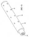
- the dual stage inflator 10comprises an outer housing 11, a first end 20, and a second end 21, all collectively forming a pressure vessel 12 that is filled with stored gas 13.
- the dual stage inflator 10has a generally cylindrical shape and may comprise stainless steel, low carbon steel, or any other suitable material, which has sufficient strength and extremely low gas permeability.
- the stored gas 13is inert, is not highly temperature sensitive, and has a high inflation rate.
- the stored gas 13comprises one or more gases, including but is not limited to argon, carbon dioxide, oxygen, helium, and nitrogen.
- the pressure vessel 12is filled with stored gas 13 through a gas fill port 14, which can be located on either end of the dual stage inflator 10.
- the gas fill port 14is sealed by a plug 15 made from low carbon steel.
- the plug 15is secured to the gas fill port 14 by a resistance weld, but other types of welding could be utilized.
- the dual stage inflator 10has a first end 20 having a diffuser subassembly 22 and a second end 21 having a gas generator assembly 23.
- the diffuser subassembly 22comprises a burst disk 24, a diffuser 26, and an opening device 25. Actuation of the opening device 25 results in the rupturing of the burst disk 24 resulting in the stored gas 13 exiting the dual stage inflator 10 through the diffuser subassembly 22.
- the burst disk 24is attached to the legs of the diffuser 26 and seals the diffuser 26 so that stored gas 13 can not exit the dual stage inflator 10.
- the burst disk 24is shown in FIG. 2A and comprises stainless steel, inconel material, monel material, or any other suitable material that allows the burst disk 24 to open reliably at - 40 °C.
- the hardness of the burst disk 24should be between "half hard” and "full hard” to minimize burst disk 24 thickness. Hardness is the degree to which a metal will resist cutting, abrasion, penetration, bending and stretching. The indicated hardness of metals will differ somewhat with the specific apparatus and technique of measuring.
- the outer portion of the burst disk 24is attached to the diffuser 26 by a laser weld 60 but could be attached by other welding techniques.
- the inner portion of the burst disk 24is not attached to any portion of the diffuser 26 and bulges upon filling of the pressure vessel 12.
- the burst disk 24adopts a dome shape due to the force of the stored gas 13 being applied to the burst disk 24.
- the burst disk 24can be bulged in the direction of the opening device 25 by a hydro-forming process after the burst disk 24 is attached to the diffuser 26.
- the burst disk 24Upon actuation of the igniter 30, the burst disk 24 ruptures resulting in a discharge opening 28, which allows the stored gas 13 to flow into the diffuser 26 and out of the dual stage inflator 10.
- the burst disk 24can have one or more secondary discharge openings 61 to control the internal pressure of the pressure vessel 12.
- FIGS. 2B -2Dillustrate various burst disk configurations having one discharge opening 28 and at least one secondary discharge opening 61.
- the actuation of the igniter 30ruptures the burst disk 24 so there is one discharge opening 28. If the gas generant subassembly 23, described in detail below, is actuated at the same time or before the diffuser subassembly 22 is fired, than the internal pressure of the pressure vessel 12 will increase and rupture the burst disk in such a way that one or more secondary discharge openings 61 are created.
- the opening device 25is attached to a diffuser, which is connected to the outer housing 11.
- the opening device 25is positioned within 8.0 mm from the center of the burst disk 24.
- the diffuser 26comprises stainless steel, low carbon steel, or any other suitable material having sufficient structural strength and extremely low gas permeability.
- the diffuser 26is connected to the cylindrical vessel by a circumferential weld, preferably a friction weld, but other suitable welding techniques may be employed.
- the diffuser 26has a plurality of outlet ports 29 along the circumference of the diffuser 26 for directing gas flow out of the dual stage inflator 10 in a radial direction whereby the diffuser subassembly 22 is thrust neutral during release of the inflation gas.
- the stored gas 13Upon rupture of the burst disk 24, the stored gas 13 travels through the diffuser 26 and ultimately travels through the outlet ports 29. The stored gas 13 may propel fragments from the ruptured burst disk 24 and these fragments are caught by a screen 27.
- the discharge opening 28 and the secondary discharge openings 61 of the burst disk 24control the flow rate of the stored gas; thus, the inflator 10 is "choked" at the discharge opening 28 and not at the outlet ports 29.
- the opening device 25comprises an electrically actuated igniter, an end cap 33, and optionally an igniter nozzle 31.
- the opening device 25is positioned so that the longitudinal axis of the opening device 25 is essentially parallel with a longitudinal axis A of the dual stage inflator 10.
- the igniter 30communicates with a controller (not shown) via two or more electrodes, which in turn communicates with a sensor (not shown).
- the igniter 30is an electrical device that actuates the inflator when a suitable electric current is passed through an ignition resistor embedded in one or more layers of pyrotechnic compositions.
- the ignitermay be of the standard direct fire design, receiving the firing current directly from the controller, or the igniter 30 may be of an advanced design which communicates with the controller by digital signals and which contains on board the igniter an ASIC (application specific integrated circuit), firing capacitor, and related components.
- the pyrotechnic compositions in the ignitergenerate an output energy that will reliably rupture the burst disk 24.
- a suitable pyrotechnic composition or ignition material for the present inventionis zirconium potassium perchlorate or ZPP, however, other ignition materials could be used.
- An end cap 33is a metal member that houses the igniter 30.
- the end cap 33may also be made from a plastic material made from an injection molding process.
- the end cap 33has threads for attachment to an airbag module (not shown).
- the opening device 25may also comprise an igniter nozzle 31 for directing output energy from the ignition of the ignition material towards the burst disk 24.
- the nozzleis tapered inward in the direction of the burst disk 24. Without the igniter nozzle 31, the igniter 30 would still rupture the burst disk 24 but will need to be loaded with extra ignition material to provide consistent opening at -40 °C. It is also possible to utilize an igniter 30 with reinforced walls, which would eliminate the need for a nozzle 31. These reinforcement walls would act in a similar fashion to the nozzle 31 by focusing the output energy in the direction of the burst disk 24.
- the gas generator subassembly 23is situated on a second end 21 of the inflator as the diffuser subassembly 22.
- the gas generator subassembly 23has an igniter 40 for receiving an electrical signal from a controller (not shown) via two or more electrodes 41 which in turn communicate with a sensor means (not shown).
- the igniter 30is an electrical device that initiates the deployment of the inflator when a suitable electric current is passed through a resistor embedded in one or more layers of pyrotechnic compositions.
- the ignitermay be of the standard direct fire design, receiving the firing current directly from the controller, or the igniter 30 may be of an advanced design which communicates with the controller by digital signals and which contains on board the igniter an ASIC, firing capacitor, and related components.
- the pyrotechnic compositions in the igniter 40break through the gas tight sealing disk 46 and ignite the enhancer 47.
- a suitable pyrotechnic composition or ignition materialis zirconium potassium perchlorate. Other ignition materials can be utilized in the present invention.
- the igniter 40is encased in an igniter housing 42, which is attached to the outer housing 11.
- the enhancer 47may be any of a number of known compositions that are readily ignited by the igniter 40 and burn at a high rate and temperature. Examples of enhancers include boron potassium nitrate and non-azide formulations containing a metal.
- the gases and hot burning particles from the ignited enhancer 47exit through the pellet retainer 43 and ignite the gas generant 48.
- the gas generator subassembly 23has a cushion 44 located on the end furthest away from the enhancer 47.
- the cushion 44is a resilient member that is utilized to bias the gas generant 48 against the pellet retainer 43 to ensure the gas generant 48 pellets occupy a predetermined volume without being able to rattle.
- the pellet retainer 43is a porous wall that divides the enhancer 47 from the gas generant 48. Hot gases from the ignition of the enhancer 47 can flow through the pellet retainer 43 but neither the enhancer material nor the gas generant pellets can pass through the pellet retainer.
- Gas generant 48 compositions useful in the dual stage inflator 10include fuels such as aminotetrazoles, tetrazoles, bitetrazoles, triazoles, the metal salts thereof, nitroguanidines, guanidine nitrate, amino guanidine nitrate, and mixtures thereof; in combination with an oxidizer such as the alkali and alkaline earth metal nitrates, chlorates, perchlorates, ammonium nitrate, and mixtures thereof.
- the gas generant 48can be formed into various shapes using various techniques known to those skilled in the art.
- the gas generant subassembly housing 49retains the gas generant 48 and comprises stainless steel, low carbon steel, or other another suitable material.
- the gas generant subassembly housing 49has a plurality of apertures 45 which can be seen in FIG. 3 .
- the plurality of apertures 45are situated along the length of the gas generant subassembly housing 49, and an important facet about the size and number of apertures 45 is that the gas generator subassembly 23 remains thrust neutral during the burning of the gas generant 48.
- the apertures 45directly expose the gas generant 48 in the gas generator subassembly 23 to the conditions present in the pressure vessel 12.
- the location of the apertures 45allows the hot gases to be discharged on the walls of the outer housing 11 thus cooling and retaining solid particulates preventing a portion of the particulates from entering the diffuser subassembly 22.
- the pressure vessel 12is filled with stored gas 13
- some of the stored gas 13is able to flow into the gas generator subassembly 23 equalizing the pressure in the pressure vessel 12 with the gas generant subassembly 23.
- a sealing disk 46prevents the stored gas 13 from escaping from the dual stage inflator 10 through the gas generator subassembly 23.
- the sealing disk 46is attached by laser welding to the igniter housing 42, but could be attached by other welding techniques.
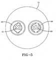
- the dual stage inflator 10 in FIG. 4has a different configuration whereby the diffuser subassembly 22 and the gas generator subassembly 23 are disposed on a first end 55 of the dual stage inflator 10.
- the diffuser subassembly 22 and the gas generator subassembly 23contain the same components as described above.
- the fill port 14can be situated on the first end 55 or the second end 56 of the dual stage inflator 10.
- FIG. 5is an end view of the embodiment in FIG. 4 showing the igniters 30, 40 of the dual stage inflator 10.
- the dual stage inflator 10offers great flexibility in the output levels of inflation gas.
- the airbag(not shown) is mounted in an airbag module with an inflator so that the airbag can receive inflation gas from the inflator.
- the dual stage inflator 10is activated by a crash sensor (not shown) and a controller (not shown).
- the preferred crash sensorsare of the type that can discern between different levels of deceleration to determine the severity of the crash.
- the vehiclecan also be equipped with other type of sensors sensing the size and position of the vehicle occupant(s).
- the crash sensorscommunicate with the controller, which processes the data signals form the sensors to determine the severity of the crash and the size and position of the vehicle occupant.
- the controllercommunicates with the igniter 40 of the gas generator subassembly 23 and with the igniter 30 of the diffuser subassembly 22.
- the first deployment scenarioa primary only output, involves the release of the stored gas 13 by the rupturing of the burst disk 24. Only the stored gas 13 is used in this scenario and may be useful for low speed crashes involving vehicle occupants that are children.
- the gas generator subassembly 23would be actuated in a timely fashion but after the crash to eliminate the pyrotechnic material from the dual stage inflator 10.
- the firing of the gas generator subassembly 23is for safety purposes to prevent inadvertent ignition and injury to vehicle occupants.
- the second deployment scenarioinvolves the actuation of the gas generator subassembly 23 after a short delay after the rupturing of the burst disk 24.
- the delaycan be set up to be between 15-30 milliseconds but it is appreciated that shorter or longer delays could be employed.
- the staged outputis used for positioning the vehicle occupant, primarily a child or small adult, for a crash.
- the ignition of the gas generant 48would produce heat resulting in the stored gas 13 escaping the vessel quicker and would produce gas which would be added to the stored gas 13 to increase the moles of gas produced by the dual stage inflator 10.
- a third deployment scenario, or full output,is contemplated by the present invention wherein both stages of the dual stage inflator 10 are initiated at the same time. This provides a large volume of gas from the inflator at a high rate and may be used for high speed crashes or larger adult vehicle occupants.
- a fourth deployment scenariois the actuation of the gas generant subassembly 23 only.
- the gas generant 48is ignited which produces hot gas, and this hot gas mixes with the stored gas 13 in the pressure vessel 12.
- the pressure of the stored gasclimbs quickly and applies enough pressure of the burst disk 24 to rupture it.
- This fourth deployment scenarioarrives at P max the quickest.
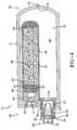
- FIG. 6shows a multiple stage inflator 70 capable of providing greater flexibility in terms of gas output characteristic / gas output profile than the dual stage inflator 10.
- the output characteristic of an inflatorconcerns inflation rate and maximum pressure in a closed environment.
- the multiple stage inflatorhas a diffuser subassembly 22, a first gas generator subassembly 65, and a second gas generator subassembly 66.
- the multiple stage inflator 70has many similarities with the dual stage inflator 10.
- the diffuser subassembly 22 for the dual stage inflator and the multiple stage inflatorhas the same physical components and is assembled in the same manner.
- the dual stage inflatorhas one gas generator subassembly, whereas the multiple stage inflator has a first gas generator subassembly 65 and a second gas generator subassembly 66.
- the first gas generator subassembly 65 and the second gas generator subassembly 66have the same physical components as the gas generator subassembly 23 in the dual stage inflator.
- the first gas generator subassembly 65 and the second gas generator subassembly 66differ by the size of the physical components and the quantity of the igniter pyrotechnic composition, enhancer 47, and gas generant 48.
- the first gas generator subassembly 65 and the second gas generator subassembly 66are attached to the second end 21 of the multiple stage inflator 10.
- the diffuser assembly 22is attached to the first end 20 of the multiple stage inflator.
- the fill port 14is situated in the center of the second end 21 of the multiple stage inflator 70, but other locations are within the scope of the present invention.
- the first gas generator subassembly housing 67is smaller than the second gas generator subassembly housing 68, and hence the quantity of gas generant 48 in the first gas generator subassembly 65 is smaller than the second gas generator subassembly 66.
- the first gas generator subassembly 65is shown in FIG. 6 as smaller than the second gas generator subassembly 66, both the first gas generator subassembly 65 and the second gas generator subassembly 66 may have equivalent dimensions.
- the first gas generator subassembly 65 and the second gas generator subassembly 66have the same physical components.
- the gas generator subassemblies 65,66operate by actuating the igniter 40, which in turn ignites the enhancer 47, which in turn ignites the gas generant 48.
- the gaseous combustion productsexit the gas generator subassemblies and travel into the pressure vessel 12.
- the first gas generator subassembly 65has a plurality of first apertures 71 arranged around the circumference thereof and the second gas generator subassembly 66 has a plurality of second apertures 72 arranged around the circumference thereof.
- the apertures 71, 72are unblocked allowing stored gas 13 to be present in the gas generators subassemblies 65,66.
- the first apertures 71do not face the second gas generator subassembly 66 and the second apertures 72 do not face the first gas generator subassembly 65.
- the first apertures 71face the second gas generator subassembly 66 if the inflation gas from the first gas generator subassembly 65 exit the first gas generator subassembly and travel in a straight line and contact the second gas generator subassembly 66.
- the second apertures 72face the first gas generator subassembly 65 if the inflation gas from the second gas generator subassembly 66 exit the second gas generator subassembly and travel in a straight line and contact the first gas generator subassembly 65.
- the aperturesmay be present at the closed end of the gas generant subassembly housing so the inflation gas exits the gas generant subassembly housing in an axial direction as opposed to a radial direction.
- the first gas generator subassembly 65is initiated whereby the increased pressure in the pressure vessel ruptures the burst disk 24.
- the second gas generator subassembly 66is initiated to safely dispose of the gas generant 48 in the second gas generator subassembly.
- the second gas generator subassembly 66is initiated whereby the increased pressure in the pressure vessel ruptures the burst disk 24.
- the first gas generator subassembly 65is initiated to safely dispose of the gas generant in the first gas generator subassembly 65.
- the first gas generator subassembly 65, the second gas generator subassembly 66, and the diffuser subassembly 22are all actuated at the same time.
- inflation gasis released at the quickest rate.
- the diffuser subasembly 22, the first gas generator subassembly 65, and the second gas generator subassembly 66are all actuated at different times whereby the diffuser assembly is actuated first.
- the diffuser assembly 22is actuated and after a delay, both the first gas generator subassembly 65 and the second gas generator subassembly 66 are actuated.
- the multiple stage inflatorhas an additional gas generator subassembly than the dual stage inflator, there are a greater number of possible deployment scenarios.
- the multiple stage inflatoroffers a greater array of output characteristics to provide the output characteristic that affords the best protection to a vehicle occupant. Also contemplated in the present invention is the ability of the multiple stage inflator to change its output characteristic in real time.
Landscapes
- Engineering & Computer Science (AREA)
- Mechanical Engineering (AREA)
- Physics & Mathematics (AREA)
- Fluid Mechanics (AREA)
- Air Bags (AREA)
- Feeding, Discharge, Calcimining, Fusing, And Gas-Generation Devices (AREA)
- Pharmaceuticals Containing Other Organic And Inorganic Compounds (AREA)
- Acyclic And Carbocyclic Compounds In Medicinal Compositions (AREA)
Abstract
Description
- The present invention relates to an inflator capable of providing various levels of inflation gas.
- An airbag filled with inflation gas provides a cushion between a vehicle occupant and the instrument panel or steering wheel. The likelihood of injury is minimized by the airbag absorbing some or all of the kinetic energy associated with the vehicle occupant during a crash. An inflator provides the inflation gas utilized to inflate an airbag.
- Dual stage inflator have been developed to reduce the injury to small adults or children by reducing the aggressiveness of airbag deployment. These inflators provide varying output levels of inflation gas in accordance with the size and position of the vehicle occupant. Dual stage inflators taught in
US 6 189 922 B1 andUS 6 168 200 B1 have first and second gas generants. Another variation of the dual stage inflator has two separate burst disks which is taught inUS 5 022 674 ,US 5 351 988 , andUS 5 016 914 . US 6 168 200 describes a dual inflator as defined in preamble portion of claim 1. Said dual inflator comprises a diffuser mounted immediately upstream of the outlet apertures of the inflator and a burst disk mounted immediately upstream of diffuser. The burst disk is adapted to fail only under the application of a predetermined pressure, thereby allowing pressurized gas to flow from chamber of inflator through outlet apertures into an air bag.US 6 206 414 teaches the use of a first burst disk designed to rupture at a different pressure than a second burst disk. Specifically, the first burst disk is designed to rupture at a lower pressure differential than the second burst disk. Because both the first burst disk and the second burst disk are exposed to ambient pressure on one side, from the diffuser chamber, the two burst disks rupture at different pressures of inflation fluid in the gas storage chamber.- There is provided in accordance with the present invention a dual stage inflator comprising a diffuser subassembly, a gas generator subassembly, and a pressure vessel. The diffuser subassembly has a burst disk and an opening device and upon actuation of the opening device, the opening device produces an output energy, which ruptures the burst disk and allows stored gas to escape the dual stage inflator through a flow control discharge opening in the burst disk.
- The dual stage inflator has various output levels associated therewith. For instance, the dual stage inflator can release only the stored gas. The inflator has the option for staged deployment whereby the stored gas is released and after a finite amount of time, the gas generant is ignited. Also, the inflator has the means for full output whereby the burst disk is ruptured at the same time the gas generator subassembly is fired. Another deployment scenario is the firing of the gas generator subassembly only.
FIG. 1 is a cross sectional view of a dual stage inflator not according to the present invention.FIGS. 2A, 2B, 2C, and 2D show various burst disk configurations.FIG. 3 is a perspective view of the gas generator subassembly.FIG. 4 is a cross sectional view of a second embodiment for a dual stage inflator.FIG. 5 is a view of a first end of the dual stage inflator shown inFIG. 4 .FIG. 6 is a cross sectional view of a multiple stage inflator in the present invention.- A dual stage inflator provides various output levels of inflation gas for inflating an airbag. The
dual stage inflator 10 comprises anouter housing 11, afirst end 20, and asecond end 21, all collectively forming apressure vessel 12 that is filled withstored gas 13. Thedual stage inflator 10 has a generally cylindrical shape and may comprise stainless steel, low carbon steel, or any other suitable material, which has sufficient strength and extremely low gas permeability. - Preferably the stored
gas 13 is inert, is not highly temperature sensitive, and has a high inflation rate. Thestored gas 13 comprises one or more gases, including but is not limited to argon, carbon dioxide, oxygen, helium, and nitrogen. - The
pressure vessel 12 is filled withstored gas 13 through agas fill port 14, which can be located on either end of thedual stage inflator 10. Thegas fill port 14 is sealed by aplug 15 made from low carbon steel. Preferably theplug 15 is secured to thegas fill port 14 by a resistance weld, but other types of welding could be utilized. - In
FIG. 1 , thedual stage inflator 10 has afirst end 20 having adiffuser subassembly 22 and asecond end 21 having agas generator assembly 23. Thediffuser subassembly 22 comprises aburst disk 24, adiffuser 26, and anopening device 25. Actuation of theopening device 25 results in the rupturing of theburst disk 24 resulting in thestored gas 13 exiting thedual stage inflator 10 through thediffuser subassembly 22. - The
burst disk 24 is attached to the legs of thediffuser 26 and seals thediffuser 26 so that storedgas 13 can not exit thedual stage inflator 10. Theburst disk 24 is shown inFIG. 2A and comprises stainless steel, inconel material, monel material, or any other suitable material that allows theburst disk 24 to open reliably at - 40 °C. The hardness of theburst disk 24 should be between "half hard" and "full hard" to minimizeburst disk 24 thickness. Hardness is the degree to which a metal will resist cutting, abrasion, penetration, bending and stretching. The indicated hardness of metals will differ somewhat with the specific apparatus and technique of measuring. The outer portion of theburst disk 24 is attached to thediffuser 26 by alaser weld 60 but could be attached by other welding techniques. The inner portion of theburst disk 24 is not attached to any portion of thediffuser 26 and bulges upon filling of thepressure vessel 12. Theburst disk 24 adopts a dome shape due to the force of thestored gas 13 being applied to theburst disk 24. Alternatively, theburst disk 24 can be bulged in the direction of theopening device 25 by a hydro-forming process after theburst disk 24 is attached to thediffuser 26. Upon actuation of theigniter 30, theburst disk 24 ruptures resulting in adischarge opening 28, which allows thestored gas 13 to flow into thediffuser 26 and out of thedual stage inflator 10. Theburst disk 24 can have one or moresecondary discharge openings 61 to control the internal pressure of thepressure vessel 12.FIGS. 2B -2D illustrate various burst disk configurations having one discharge opening 28 and at least one secondary discharge opening 61. The actuation of theigniter 30 ruptures theburst disk 24 so there is one discharge opening 28. If the gasgenerant subassembly 23, described in detail below, is actuated at the same time or before thediffuser subassembly 22 is fired, than the internal pressure of thepressure vessel 12 will increase and rupture the burst disk in such a way that one or moresecondary discharge openings 61 are created. - The
opening device 25 is attached to a diffuser, which is connected to theouter housing 11. Theopening device 25 is positioned within 8.0 mm from the center of theburst disk 24. Thediffuser 26 comprises stainless steel, low carbon steel, or any other suitable material having sufficient structural strength and extremely low gas permeability. Thediffuser 26 is connected to the cylindrical vessel by a circumferential weld, preferably a friction weld, but other suitable welding techniques may be employed. Thediffuser 26 has a plurality ofoutlet ports 29 along the circumference of thediffuser 26 for directing gas flow out of thedual stage inflator 10 in a radial direction whereby thediffuser subassembly 22 is thrust neutral during release of the inflation gas. Upon rupture of theburst disk 24, thestored gas 13 travels through thediffuser 26 and ultimately travels through theoutlet ports 29. Thestored gas 13 may propel fragments from the rupturedburst disk 24 and these fragments are caught by ascreen 27. The discharge opening 28 and thesecondary discharge openings 61 of theburst disk 24 control the flow rate of the stored gas; thus, theinflator 10 is "choked" at the discharge opening 28 and not at theoutlet ports 29. - The
opening device 25 comprises an electrically actuated igniter, anend cap 33, and optionally anigniter nozzle 31. Theopening device 25 is positioned so that the longitudinal axis of theopening device 25 is essentially parallel with a longitudinal axis A of thedual stage inflator 10. Theigniter 30 communicates with a controller (not shown) via two or more electrodes, which in turn communicates with a sensor (not shown). Theigniter 30 is an electrical device that actuates the inflator when a suitable electric current is passed through an ignition resistor embedded in one or more layers of pyrotechnic compositions. The igniter may be of the standard direct fire design, receiving the firing current directly from the controller, or theigniter 30 may be of an advanced design which communicates with the controller by digital signals and which contains on board the igniter an ASIC (application specific integrated circuit), firing capacitor, and related components. The pyrotechnic compositions in the igniter generate an output energy that will reliably rupture theburst disk 24. A suitable pyrotechnic composition or ignition material for the present invention is zirconium potassium perchlorate or ZPP, however, other ignition materials could be used. - An
end cap 33 is a metal member that houses theigniter 30. Theend cap 33 may also be made from a plastic material made from an injection molding process. InFIG. 1 theend cap 33 has threads for attachment to an airbag module (not shown). - The
opening device 25 may also comprise anigniter nozzle 31 for directing output energy from the ignition of the ignition material towards theburst disk 24. The nozzle is tapered inward in the direction of theburst disk 24. Without theigniter nozzle 31, theigniter 30 would still rupture theburst disk 24 but will need to be loaded with extra ignition material to provide consistent opening at -40 °C. It is also possible to utilize anigniter 30 with reinforced walls, which would eliminate the need for anozzle 31. These reinforcement walls would act in a similar fashion to thenozzle 31 by focusing the output energy in the direction of theburst disk 24. - In
FIG. 1 thegas generator subassembly 23 is situated on asecond end 21 of the inflator as thediffuser subassembly 22. Thegas generator subassembly 23 has anigniter 40 for receiving an electrical signal from a controller (not shown) via two ormore electrodes 41 which in turn communicate with a sensor means (not shown). Theigniter 30 is an electrical device that initiates the deployment of the inflator when a suitable electric current is passed through a resistor embedded in one or more layers of pyrotechnic compositions. The igniter may be of the standard direct fire design, receiving the firing current directly from the controller, or theigniter 30 may be of an advanced design which communicates with the controller by digital signals and which contains on board the igniter an ASIC, firing capacitor, and related components. - The pyrotechnic compositions in the
igniter 40 break through the gastight sealing disk 46 and ignite theenhancer 47. A suitable pyrotechnic composition or ignition material is zirconium potassium perchlorate. Other ignition materials can be utilized in the present invention. Theigniter 40 is encased in anigniter housing 42, which is attached to theouter housing 11. - The
enhancer 47 may be any of a number of known compositions that are readily ignited by theigniter 40 and burn at a high rate and temperature. Examples of enhancers include boron potassium nitrate and non-azide formulations containing a metal. The gases and hot burning particles from the ignitedenhancer 47 exit through thepellet retainer 43 and ignite thegas generant 48. Thegas generator subassembly 23 has acushion 44 located on the end furthest away from theenhancer 47. Thecushion 44 is a resilient member that is utilized to bias thegas generant 48 against thepellet retainer 43 to ensure thegas generant 48 pellets occupy a predetermined volume without being able to rattle. Thepellet retainer 43 is a porous wall that divides theenhancer 47 from thegas generant 48. Hot gases from the ignition of theenhancer 47 can flow through thepellet retainer 43 but neither the enhancer material nor the gas generant pellets can pass through the pellet retainer. Gas generant 48 compositions useful in thedual stage inflator 10 include fuels such as aminotetrazoles, tetrazoles, bitetrazoles, triazoles, the metal salts thereof, nitroguanidines, guanidine nitrate, amino guanidine nitrate, and mixtures thereof; in combination with an oxidizer such as the alkali and alkaline earth metal nitrates, chlorates, perchlorates, ammonium nitrate, and mixtures thereof. The gas generant 48 can be formed into various shapes using various techniques known to those skilled in the art.- The gas
generant subassembly housing 49 retains thegas generant 48 and comprises stainless steel, low carbon steel, or other another suitable material. The gasgenerant subassembly housing 49 has a plurality ofapertures 45 which can be seen inFIG. 3 . The plurality ofapertures 45 are situated along the length of the gasgenerant subassembly housing 49, and an important facet about the size and number ofapertures 45 is that thegas generator subassembly 23 remains thrust neutral during the burning of thegas generant 48. Theapertures 45 directly expose thegas generant 48 in thegas generator subassembly 23 to the conditions present in thepressure vessel 12. The location of theapertures 45 allows the hot gases to be discharged on the walls of theouter housing 11 thus cooling and retaining solid particulates preventing a portion of the particulates from entering thediffuser subassembly 22. When thepressure vessel 12 is filled with storedgas 13, some of the storedgas 13 is able to flow into thegas generator subassembly 23 equalizing the pressure in thepressure vessel 12 with thegas generant subassembly 23. Asealing disk 46 prevents the storedgas 13 from escaping from thedual stage inflator 10 through thegas generator subassembly 23. Thesealing disk 46 is attached by laser welding to theigniter housing 42, but could be attached by other welding techniques. - The
dual stage inflator 10 inFIG. 4 has a different configuration whereby thediffuser subassembly 22 and thegas generator subassembly 23 are disposed on afirst end 55 of thedual stage inflator 10. For this embodiment thediffuser subassembly 22 and thegas generator subassembly 23 contain the same components as described above. Thefill port 14 can be situated on thefirst end 55 or thesecond end 56 of thedual stage inflator 10. FIG. 5 is an end view of the embodiment inFIG. 4 showing theigniters dual stage inflator 10.- The
dual stage inflator 10 according to the present invention offers great flexibility in the output levels of inflation gas. The airbag (not shown) is mounted in an airbag module with an inflator so that the airbag can receive inflation gas from the inflator. Thedual stage inflator 10 is activated by a crash sensor (not shown) and a controller (not shown). The preferred crash sensors are of the type that can discern between different levels of deceleration to determine the severity of the crash. The vehicle can also be equipped with other type of sensors sensing the size and position of the vehicle occupant(s). The crash sensors communicate with the controller, which processes the data signals form the sensors to determine the severity of the crash and the size and position of the vehicle occupant. At the onset of a crash, the controller communicates with theigniter 40 of thegas generator subassembly 23 and with theigniter 30 of thediffuser subassembly 22. - There are four deployment scenarios anticipated by the dual stage hybrid inflator. The first deployment scenario, a primary only output, involves the release of the stored
gas 13 by the rupturing of theburst disk 24. Only the storedgas 13 is used in this scenario and may be useful for low speed crashes involving vehicle occupants that are children. Thegas generator subassembly 23 would be actuated in a timely fashion but after the crash to eliminate the pyrotechnic material from thedual stage inflator 10. The firing of thegas generator subassembly 23 is for safety purposes to prevent inadvertent ignition and injury to vehicle occupants. - The second deployment scenario, a staged output, involves the actuation of the
gas generator subassembly 23 after a short delay after the rupturing of theburst disk 24. The delay can be set up to be between 15-30 milliseconds but it is appreciated that shorter or longer delays could be employed. The staged output is used for positioning the vehicle occupant, primarily a child or small adult, for a crash. The ignition of thegas generant 48 would produce heat resulting in the storedgas 13 escaping the vessel quicker and would produce gas which would be added to the storedgas 13 to increase the moles of gas produced by thedual stage inflator 10. - A third deployment scenario, or full output, is contemplated by the present invention wherein both stages of the
dual stage inflator 10 are initiated at the same time. This provides a large volume of gas from the inflator at a high rate and may be used for high speed crashes or larger adult vehicle occupants. - A fourth deployment scenario is the actuation of the
gas generant subassembly 23 only. During this secondary deployment scenario, thegas generant 48 is ignited which produces hot gas, and this hot gas mixes with the storedgas 13 in thepressure vessel 12. The pressure of the stored gas climbs quickly and applies enough pressure of theburst disk 24 to rupture it. This fourth deployment scenario arrives at Pmax the quickest. FIG. 6 shows amultiple stage inflator 70 capable of providing greater flexibility in terms of gas output characteristic / gas output profile than thedual stage inflator 10. The output characteristic of an inflator concerns inflation rate and maximum pressure in a closed environment. The multiple stage inflator has adiffuser subassembly 22, a firstgas generator subassembly 65, and a secondgas generator subassembly 66. Themultiple stage inflator 70 has many similarities with thedual stage inflator 10. Thediffuser subassembly 22 for the dual stage inflator and the multiple stage inflator has the same physical components and is assembled in the same manner. The dual stage inflator has one gas generator subassembly, whereas the multiple stage inflator has a firstgas generator subassembly 65 and a secondgas generator subassembly 66. The firstgas generator subassembly 65 and the secondgas generator subassembly 66 have the same physical components as thegas generator subassembly 23 in the dual stage inflator. The firstgas generator subassembly 65 and the secondgas generator subassembly 66 differ by the size of the physical components and the quantity of the igniter pyrotechnic composition,enhancer 47, andgas generant 48.- The first
gas generator subassembly 65 and the secondgas generator subassembly 66 are attached to thesecond end 21 of themultiple stage inflator 10. Thediffuser assembly 22 is attached to thefirst end 20 of the multiple stage inflator. InFIG. 6 , thefill port 14 is situated in the center of thesecond end 21 of themultiple stage inflator 70, but other locations are within the scope of the present invention. InFIG. 6 the first gasgenerator subassembly housing 67 is smaller than the second gasgenerator subassembly housing 68, and hence the quantity ofgas generant 48 in the firstgas generator subassembly 65 is smaller than the secondgas generator subassembly 66. Even though the firstgas generator subassembly 65 is shown inFIG. 6 as smaller than the secondgas generator subassembly 66, both the firstgas generator subassembly 65 and the secondgas generator subassembly 66 may have equivalent dimensions. - The first
gas generator subassembly 65 and the secondgas generator subassembly 66 have the same physical components. Thegas generator subassemblies igniter 40, which in turn ignites theenhancer 47, which in turn ignites thegas generant 48. The gaseous combustion products exit the gas generator subassemblies and travel into thepressure vessel 12. The firstgas generator subassembly 65 has a plurality offirst apertures 71 arranged around the circumference thereof and the secondgas generator subassembly 66 has a plurality ofsecond apertures 72 arranged around the circumference thereof. Theapertures gas 13 to be present in thegas generators subassemblies gas generator assembly 65 from the secondgas generator subassembly 66, and vice versa, thefirst apertures 71 do not face the secondgas generator subassembly 66 and thesecond apertures 72 do not face the firstgas generator subassembly 65. As used herein, thefirst apertures 71 face the secondgas generator subassembly 66 if the inflation gas from the firstgas generator subassembly 65 exit the first gas generator subassembly and travel in a straight line and contact the secondgas generator subassembly 66. Thesecond apertures 72 face the firstgas generator subassembly 65 if the inflation gas from the secondgas generator subassembly 66 exit the second gas generator subassembly and travel in a straight line and contact the firstgas generator subassembly 65. The apertures may be present at the closed end of the gas generant subassembly housing so the inflation gas exits the gas generant subassembly housing in an axial direction as opposed to a radial direction. - The contemplated deployment scenarios for the dual stage inflator were discussed above. Since the multiple stage inflator has an additional gas generator assembly than the dual stage inflator, there are additional possible deployment scenarios.
- In a first deployment scenario, the first
gas generator subassembly 65 is initiated whereby the increased pressure in the pressure vessel ruptures theburst disk 24. After a predetermined period of time, the secondgas generator subassembly 66 is initiated to safely dispose of thegas generant 48 in the second gas generator subassembly. - In a second deployment scenario, the second
gas generator subassembly 66 is initiated whereby the increased pressure in the pressure vessel ruptures theburst disk 24. After a predetermined period of time, the firstgas generator subassembly 65 is initiated to safely dispose of the gas generant in the firstgas generator subassembly 65. - In a third deployment scenario, the first
gas generator subassembly 65, the secondgas generator subassembly 66, and thediffuser subassembly 22 are all actuated at the same time. In this scenario, inflation gas is released at the quickest rate. - In a fourth deployment scenario, the
diffuser subasembly 22, the firstgas generator subassembly 65, and the secondgas generator subassembly 66 are all actuated at different times whereby the diffuser assembly is actuated first. - In a fifth deployment scenario, the
diffuser assembly 22 is actuated and after a delay, both the firstgas generator subassembly 65 and the secondgas generator subassembly 66 are actuated. - Since the multiple stage inflator has an additional gas generator subassembly than the dual stage inflator, there are a greater number of possible deployment scenarios. The multiple stage inflator offers a greater array of output characteristics to provide the output characteristic that affords the best protection to a vehicle occupant. Also contemplated in the present invention is the ability of the multiple stage inflator to change its output characteristic in real time.
Claims (9)
- An inflator (10) comprising:(a) an outer housing (11) having a first end (20) and a second end (21) attached on opposite ends, whereby the outer housing (11), the first end (20), and the second end (21) define a pressure vessel containing stored gas (13);(b) a diffuser subassembly (22) disposed on the first end (20) of the outer housing (11);(c) a first gas generator subassembly (65) disposed on the second end (21), the first gas generator subassembly comprising an igniter (40), an enhancer (47), and a gas generant (48); and(d) a second gas generator subassembly (66) disposed on the second end (21), the second gas generator subassembly comprising an igniter (40), an enhancer (47), and a gas generant (48);characterized by the first gas generator assembly (65) being spaced apart from the second gas generator assembly (66) with stored gas located between them, and the diffuser subassembly (22) comprising a burst disk (24) and an opening device (25) that is an igniter (30) positioned so that a longitudinal axis of the opening device is essentially parallel with a longitudinal axis (A) of the inflator (10).
- An inflator (10) according to claim 1 wherein the center of the burst disk (24) is less than 8.0 mm away from the opening device.
- An inflator (10) according to either of claims 1 or 2 wherein the gas exits the inflator (10) in substantially a radial direction resulting in a neutral thrust.
- An inflator (10) according to any of claims 1 - 3 wherein the first gas generator subassembly (65) holds less gas generant (48) than the second gas generator subassembly (66).
- An inflator (10) according to any of claims 1 - 3 wherein the first gas generator subassembly (65) has an equivalent quantity of gas generant (48) as the gas generant (48) in the second gas generator subassembly (66).
- An inflator (10) according to any of claims 1 - 5 wherein the first gas generator subassembly (65) comprises a first gas generator subassembly housing (67) for partially surrounding the gas generant (48), the first gas generator subassembly housing (67) has first apertures (71) therethrough arranged around the circumference of the first gas generator subassembly (67).
- An inflator (10) according to claim 6 wherein the second gas generator subassembly (66) comprises a second gas generator subassembly housing (68) for partially surrounding the gas generant (48), the second gas generator subassembly housing (68) has second apertures (72) therethrough arranged around the circumference of the second gas generator subassembly (68) whereby the second apertures (72) do not face the first apertures (71).
- An inflator (10) according to claim 7 wherein the stored gas (13) is disposed between the first gas generator subassembly housing (67) and the outer housing (11), wherein the stored gas (13) is disposed between the second gas generator subassembly housing (68) and the outer housing (11).
- An inflator (10) according to claim 8 wherein the stored gas (13) is mixed with gas generant in the first gas generator subassembly (65), the stored gas (13) is mixed with the gas generant (48) in the second gas generator subassembly (66).
Applications Claiming Priority (2)
| Application Number | Priority Date | Filing Date | Title |
|---|---|---|---|
| US10/457,992US6874814B2 (en) | 2002-06-13 | 2003-06-11 | Multiple stage inflator |
| PCT/US2004/006588WO2005005202A2 (en) | 2003-06-11 | 2004-03-05 | Multiple stage inflator |
Publications (3)
| Publication Number | Publication Date |
|---|---|
| EP1631480A2 EP1631480A2 (en) | 2006-03-08 |
| EP1631480A4 EP1631480A4 (en) | 2006-08-16 |
| EP1631480B1true EP1631480B1 (en) | 2009-08-12 |
Family
ID=34061870
Family Applications (1)
| Application Number | Title | Priority Date | Filing Date |
|---|---|---|---|
| EP04717931AExpired - LifetimeEP1631480B1 (en) | 2003-06-11 | 2004-03-05 | Multiple stage inflator |
Country Status (7)
| Country | Link |
|---|---|
| US (1) | US6874814B2 (en) |
| EP (1) | EP1631480B1 (en) |
| JP (1) | JP4167284B2 (en) |
| KR (1) | KR100669853B1 (en) |
| AT (1) | ATE439278T1 (en) |
| DE (1) | DE602004022542D1 (en) |
| WO (1) | WO2005005202A2 (en) |
Families Citing this family (23)
| Publication number | Priority date | Publication date | Assignee | Title |
|---|---|---|---|---|
| US7431335B2 (en) | 2003-09-17 | 2008-10-07 | Automotive Systems Laboratory, Inc. | Pyrotechnic stored gas inflator |
| US7393009B2 (en)* | 2004-09-30 | 2008-07-01 | Automotive Systems Laboratory, Inc. | Dual-flow inflator |
| GB2422650B (en)* | 2005-01-27 | 2007-10-03 | Autoliv Dev | Improvements in or relating to an air-bag inflator |
| FR2894658B1 (en)* | 2005-12-13 | 2010-11-12 | Livbag | HYBRID TYPE GAS GENERATOR, COMPRISING A METAL LOAD. |
| US7980590B2 (en)* | 2008-03-19 | 2011-07-19 | Amsafe, Inc. | Inflatable personal restraint systems having web-mounted inflators and associated methods of use and manufacture |
| US7665761B1 (en) | 2008-03-27 | 2010-02-23 | Amsafe, Inc. | Inflatable personal restraint systems and associated methods of use and manufacture |
| FR2932136B1 (en)* | 2008-06-06 | 2010-08-20 | Livbag | PYROTECHNIC GAS GENERATOR WITH COMBUSTION AND DIFFUSION CHAMBERS OF DIFFERENT SECTIONS |
| US8047569B2 (en)* | 2010-03-12 | 2011-11-01 | Autoliv Asp, Inc. | Multi-stage inflator |
| US9321426B1 (en) | 2010-04-28 | 2016-04-26 | Tk Holdings, Inc. | Container for gas generant |
| US9156558B2 (en) | 2011-04-05 | 2015-10-13 | Amsafe, Inc. | Inflatable personal restraint systems |
| US8469397B2 (en) | 2011-04-13 | 2013-06-25 | Amsafe, Inc. | Stitch patterns for restraint-mounted airbags and associated systems and methods |
| US8439398B2 (en) | 2011-07-29 | 2013-05-14 | Amsafe, Inc. | Inflator connectors for inflatable personal restraints and associated systems and methods |
| US9511866B2 (en) | 2012-03-19 | 2016-12-06 | Amsafe, Inc. | Structure mounted airbag assemblies and associated systems and methods |
| US8523220B1 (en) | 2012-03-19 | 2013-09-03 | Amsafe, Inc. | Structure mounted airbag assemblies and associated systems and methods |
| DE102012023031B4 (en)* | 2012-11-26 | 2023-02-23 | Zf Automotive Germany Gmbh | Belt tensioner for a vehicle occupant restraint system |
| JP2015080987A (en)* | 2013-10-22 | 2015-04-27 | 株式会社ダイセル | Rupture disk and inflator using the same |
| US9352839B2 (en) | 2014-10-02 | 2016-05-31 | Amsafe, Inc. | Active positioning airbag assembly and associated systems and methods |
| US9944245B2 (en) | 2015-03-28 | 2018-04-17 | Amsafe, Inc. | Extending pass-through airbag occupant restraint systems, and associated systems and methods |
| CN107428308A (en) | 2015-04-11 | 2017-12-01 | Am-安全公司 | Active Airbag Exhaust System |
| US10604259B2 (en) | 2016-01-20 | 2020-03-31 | Amsafe, Inc. | Occupant restraint systems having extending restraints, and associated systems and methods |
| DE102016002937A1 (en)* | 2016-03-11 | 2017-09-14 | Trw Airbag Systems Gmbh | Hybrid gas generator, gas bag unit and vehicle safety system with such a hybrid gas generator and method for forming a shock wave |
| US10054265B2 (en)* | 2016-11-29 | 2018-08-21 | Goodrich Corporation | System and method for a heated gas cylinder assembly |
| MX2021009409A (en) | 2019-02-06 | 2021-12-10 | Boost Ideas Llc | WATER SAFETY ITEM OF CLOTHING, APPLIANCE AND RELATED METHODS. |
Family Cites Families (11)
| Publication number | Priority date | Publication date | Assignee | Title |
|---|---|---|---|---|
| US5016914A (en) | 1990-02-14 | 1991-05-21 | Trw Vehicle Safety Systems Inc. | Vehicle occupant restraint system |
| US5022674A (en) | 1990-04-05 | 1991-06-11 | Bendix Atlantic Inflator Company | Dual pyrotechnic hybrid inflator |
| US5351988A (en) | 1990-11-27 | 1994-10-04 | Alliedsignal Inc. | Hybrid inflator with staged inflation capability |
| US5351989A (en)* | 1992-11-30 | 1994-10-04 | Trw Vehicle Safety Systems Inc. | Inflator assembly |
| US5577769A (en)* | 1995-06-13 | 1996-11-26 | Atlantic Research Corporation | Hybrid inflator for inflating air bags |
| US5743557A (en)* | 1996-05-07 | 1998-04-28 | Amphenol-Tuchel Electronics Gmbh | Hybrid inflator |
| US6019389A (en)* | 1998-03-31 | 2000-02-01 | Trw Vehicle Safety Systems Inc. | Air bag inflator |
| US6206414B1 (en)* | 1998-08-05 | 2001-03-27 | Trw Inc. | Air bag inflator including plural burst disks |
| US6189922B1 (en) | 1998-09-21 | 2001-02-20 | Autoliv Asp Inc. | Inflator with multiple initiators |
| US6168200B1 (en)* | 1998-12-01 | 2001-01-02 | Atlantic Research Corporation | Dual level inflator |
| US6382668B1 (en)* | 2000-11-16 | 2002-05-07 | Trw Vehicle Safety Systems Inc. | Air bag inflator |
- 2003
- 2003-06-11USUS10/457,992patent/US6874814B2/ennot_activeExpired - Lifetime
- 2004
- 2004-03-05DEDE602004022542Tpatent/DE602004022542D1/ennot_activeExpired - Lifetime
- 2004-03-05WOPCT/US2004/006588patent/WO2005005202A2/enactiveApplication Filing
- 2004-03-05ATAT04717931Tpatent/ATE439278T1/ennot_activeIP Right Cessation
- 2004-03-05KRKR1020057023639Apatent/KR100669853B1/ennot_activeExpired - Fee Related
- 2004-03-05JPJP2006509124Apatent/JP4167284B2/ennot_activeExpired - Fee Related
- 2004-03-05EPEP04717931Apatent/EP1631480B1/ennot_activeExpired - Lifetime
Also Published As
| Publication number | Publication date |
|---|---|
| US20030230882A1 (en) | 2003-12-18 |
| WO2005005202A2 (en) | 2005-01-20 |
| JP2006527123A (en) | 2006-11-30 |
| KR20060021355A (en) | 2006-03-07 |
| DE602004022542D1 (en) | 2009-09-24 |
| EP1631480A2 (en) | 2006-03-08 |
| ATE439278T1 (en) | 2009-08-15 |
| US6874814B2 (en) | 2005-04-05 |
| WO2005005202A3 (en) | 2005-06-09 |
| EP1631480A4 (en) | 2006-08-16 |
| KR100669853B1 (en) | 2007-01-16 |
| JP4167284B2 (en) | 2008-10-15 |
Similar Documents
| Publication | Publication Date | Title |
|---|---|---|
| EP1631480B1 (en) | Multiple stage inflator | |
| CA2427540C (en) | Low onset dual stage hybrid inflator | |
| US6908104B2 (en) | Pyrotechnic side impact inflator | |
| EP1775180A2 (en) | Dual stage hybrid airbag inflator | |
| US5794973A (en) | Dual stage air bag inflator | |
| EP0558651B1 (en) | Hybrid inflator | |
| US6149193A (en) | Variable output inflator | |
| EP1262381B1 (en) | Airbag gas generator | |
| US5762368A (en) | Initiator for air bag inflator | |
| JP2609404B2 (en) | Igniters and expanders | |
| US6857657B2 (en) | Inflator having a support member capable of sliding to open the pressure vessel | |
| US6126197A (en) | Lightweight discoidal filterless air bag inflator | |
| KR100254711B1 (en) | Apparatus and method for inflating a vehicle occupant prote ction device | |
| US7806436B2 (en) | Gas generating system | |
| US6007097A (en) | Flammable gas initiated pyrotechnic inflator | |
| US6976704B2 (en) | Adaptive output airbag inflation device | |
| JPH07502470A (en) | hybrid inflator | |
| WO1996040541A1 (en) | Airbag inflator system | |
| KR100390076B1 (en) | Hybrid inflator with rapid pressurization based flow initiation assembly | |
| JP4860809B2 (en) | Gas generator for airbag and airbag device | |
| KR0156298B1 (en) | Automotive airbag inflator ignited by combustible gas and its deployment method |
Legal Events
| Date | Code | Title | Description |
|---|---|---|---|
| PUAI | Public reference made under article 153(3) epc to a published international application that has entered the european phase | Free format text:ORIGINAL CODE: 0009012 | |
| 17P | Request for examination filed | Effective date:20050629 | |
| AK | Designated contracting states | Kind code of ref document:A2 Designated state(s):AT BE BG CH CY CZ DE DK EE ES FI FR GB GR HU IE IT LI LU MC NL PL PT RO SE SI SK TR | |
| A4 | Supplementary search report drawn up and despatched | Effective date:20060718 | |
| DAX | Request for extension of the european patent (deleted) | ||
| 17Q | First examination report despatched | Effective date:20061030 | |
| GRAP | Despatch of communication of intention to grant a patent | Free format text:ORIGINAL CODE: EPIDOSNIGR1 | |
| GRAS | Grant fee paid | Free format text:ORIGINAL CODE: EPIDOSNIGR3 | |
| GRAA | (expected) grant | Free format text:ORIGINAL CODE: 0009210 | |
| AK | Designated contracting states | Kind code of ref document:B1 Designated state(s):AT BE BG CH CY CZ DE DK EE ES FI FR GB GR HU IE IT LI LU MC NL PL PT RO SE SI SK TR | |
| REG | Reference to a national code | Ref country code:GB Ref legal event code:FG4D | |
| REG | Reference to a national code | Ref country code:CH Ref legal event code:EP | |
| REG | Reference to a national code | Ref country code:IE Ref legal event code:FG4D | |
| REF | Corresponds to: | Ref document number:602004022542 Country of ref document:DE Date of ref document:20090924 Kind code of ref document:P | |
| PG25 | Lapsed in a contracting state [announced via postgrant information from national office to epo] | Ref country code:SE Free format text:LAPSE BECAUSE OF FAILURE TO SUBMIT A TRANSLATION OF THE DESCRIPTION OR TO PAY THE FEE WITHIN THE PRESCRIBED TIME-LIMIT Effective date:20090812 Ref country code:FI Free format text:LAPSE BECAUSE OF FAILURE TO SUBMIT A TRANSLATION OF THE DESCRIPTION OR TO PAY THE FEE WITHIN THE PRESCRIBED TIME-LIMIT Effective date:20090812 Ref country code:AT Free format text:LAPSE BECAUSE OF FAILURE TO SUBMIT A TRANSLATION OF THE DESCRIPTION OR TO PAY THE FEE WITHIN THE PRESCRIBED TIME-LIMIT Effective date:20090812 Ref country code:ES Free format text:LAPSE BECAUSE OF FAILURE TO SUBMIT A TRANSLATION OF THE DESCRIPTION OR TO PAY THE FEE WITHIN THE PRESCRIBED TIME-LIMIT Effective date:20091123 | |
| NLV1 | Nl: lapsed or annulled due to failure to fulfill the requirements of art. 29p and 29m of the patents act | ||
| PG25 | Lapsed in a contracting state [announced via postgrant information from national office to epo] | Ref country code:NL Free format text:LAPSE BECAUSE OF FAILURE TO SUBMIT A TRANSLATION OF THE DESCRIPTION OR TO PAY THE FEE WITHIN THE PRESCRIBED TIME-LIMIT Effective date:20090812 Ref country code:SI Free format text:LAPSE BECAUSE OF FAILURE TO SUBMIT A TRANSLATION OF THE DESCRIPTION OR TO PAY THE FEE WITHIN THE PRESCRIBED TIME-LIMIT Effective date:20090812 Ref country code:PL Free format text:LAPSE BECAUSE OF FAILURE TO SUBMIT A TRANSLATION OF THE DESCRIPTION OR TO PAY THE FEE WITHIN THE PRESCRIBED TIME-LIMIT Effective date:20090812 | |
| PG25 | Lapsed in a contracting state [announced via postgrant information from national office to epo] | Ref country code:PT Free format text:LAPSE BECAUSE OF FAILURE TO SUBMIT A TRANSLATION OF THE DESCRIPTION OR TO PAY THE FEE WITHIN THE PRESCRIBED TIME-LIMIT Effective date:20091212 Ref country code:BG Free format text:LAPSE BECAUSE OF FAILURE TO SUBMIT A TRANSLATION OF THE DESCRIPTION OR TO PAY THE FEE WITHIN THE PRESCRIBED TIME-LIMIT Effective date:20091112 | |
| PG25 | Lapsed in a contracting state [announced via postgrant information from national office to epo] | Ref country code:CZ Free format text:LAPSE BECAUSE OF FAILURE TO SUBMIT A TRANSLATION OF THE DESCRIPTION OR TO PAY THE FEE WITHIN THE PRESCRIBED TIME-LIMIT Effective date:20090812 Ref country code:RO Free format text:LAPSE BECAUSE OF FAILURE TO SUBMIT A TRANSLATION OF THE DESCRIPTION OR TO PAY THE FEE WITHIN THE PRESCRIBED TIME-LIMIT Effective date:20090812 Ref country code:EE Free format text:LAPSE BECAUSE OF FAILURE TO SUBMIT A TRANSLATION OF THE DESCRIPTION OR TO PAY THE FEE WITHIN THE PRESCRIBED TIME-LIMIT Effective date:20090812 Ref country code:DK Free format text:LAPSE BECAUSE OF FAILURE TO SUBMIT A TRANSLATION OF THE DESCRIPTION OR TO PAY THE FEE WITHIN THE PRESCRIBED TIME-LIMIT Effective date:20090812 | |
| PG25 | Lapsed in a contracting state [announced via postgrant information from national office to epo] | Ref country code:SK Free format text:LAPSE BECAUSE OF FAILURE TO SUBMIT A TRANSLATION OF THE DESCRIPTION OR TO PAY THE FEE WITHIN THE PRESCRIBED TIME-LIMIT Effective date:20090812 | |
| PLBE | No opposition filed within time limit | Free format text:ORIGINAL CODE: 0009261 | |
| STAA | Information on the status of an ep patent application or granted ep patent | Free format text:STATUS: NO OPPOSITION FILED WITHIN TIME LIMIT | |
| PG25 | Lapsed in a contracting state [announced via postgrant information from national office to epo] | Ref country code:BE Free format text:LAPSE BECAUSE OF FAILURE TO SUBMIT A TRANSLATION OF THE DESCRIPTION OR TO PAY THE FEE WITHIN THE PRESCRIBED TIME-LIMIT Effective date:20090812 | |
| 26N | No opposition filed | Effective date:20100517 | |
| PG25 | Lapsed in a contracting state [announced via postgrant information from national office to epo] | Ref country code:GR Free format text:LAPSE BECAUSE OF FAILURE TO SUBMIT A TRANSLATION OF THE DESCRIPTION OR TO PAY THE FEE WITHIN THE PRESCRIBED TIME-LIMIT Effective date:20091113 Ref country code:MC Free format text:LAPSE BECAUSE OF NON-PAYMENT OF DUE FEES Effective date:20100331 | |
| REG | Reference to a national code | Ref country code:CH Ref legal event code:PL | |
| PG25 | Lapsed in a contracting state [announced via postgrant information from national office to epo] | Ref country code:IE Free format text:LAPSE BECAUSE OF NON-PAYMENT OF DUE FEES Effective date:20100305 | |
| PG25 | Lapsed in a contracting state [announced via postgrant information from national office to epo] | Ref country code:CH Free format text:LAPSE BECAUSE OF NON-PAYMENT OF DUE FEES Effective date:20100331 Ref country code:LI Free format text:LAPSE BECAUSE OF NON-PAYMENT OF DUE FEES Effective date:20100331 | |
| PG25 | Lapsed in a contracting state [announced via postgrant information from national office to epo] | Ref country code:IT Free format text:LAPSE BECAUSE OF FAILURE TO SUBMIT A TRANSLATION OF THE DESCRIPTION OR TO PAY THE FEE WITHIN THE PRESCRIBED TIME-LIMIT Effective date:20090812 | |
| PG25 | Lapsed in a contracting state [announced via postgrant information from national office to epo] | Ref country code:CY Free format text:LAPSE BECAUSE OF FAILURE TO SUBMIT A TRANSLATION OF THE DESCRIPTION OR TO PAY THE FEE WITHIN THE PRESCRIBED TIME-LIMIT Effective date:20090812 | |
| PG25 | Lapsed in a contracting state [announced via postgrant information from national office to epo] | Ref country code:LU Free format text:LAPSE BECAUSE OF NON-PAYMENT OF DUE FEES Effective date:20100305 Ref country code:HU Free format text:LAPSE BECAUSE OF FAILURE TO SUBMIT A TRANSLATION OF THE DESCRIPTION OR TO PAY THE FEE WITHIN THE PRESCRIBED TIME-LIMIT Effective date:20100213 | |
| PG25 | Lapsed in a contracting state [announced via postgrant information from national office to epo] | Ref country code:TR Free format text:LAPSE BECAUSE OF FAILURE TO SUBMIT A TRANSLATION OF THE DESCRIPTION OR TO PAY THE FEE WITHIN THE PRESCRIBED TIME-LIMIT Effective date:20090812 | |
| REG | Reference to a national code | Ref country code:FR Ref legal event code:PLFP Year of fee payment:13 | |
| REG | Reference to a national code | Ref country code:FR Ref legal event code:PLFP Year of fee payment:14 | |
| REG | Reference to a national code | Ref country code:FR Ref legal event code:PLFP Year of fee payment:15 | |
| PGFP | Annual fee paid to national office [announced via postgrant information from national office to epo] | Ref country code:GB Payment date:20180223 Year of fee payment:15 | |
| PGFP | Annual fee paid to national office [announced via postgrant information from national office to epo] | Ref country code:FR Payment date:20180223 Year of fee payment:15 | |
| GBPC | Gb: european patent ceased through non-payment of renewal fee | Effective date:20190305 | |
| PG25 | Lapsed in a contracting state [announced via postgrant information from national office to epo] | Ref country code:GB Free format text:LAPSE BECAUSE OF NON-PAYMENT OF DUE FEES Effective date:20190305 | |
| PG25 | Lapsed in a contracting state [announced via postgrant information from national office to epo] | Ref country code:FR Free format text:LAPSE BECAUSE OF NON-PAYMENT OF DUE FEES Effective date:20190331 | |
| PGFP | Annual fee paid to national office [announced via postgrant information from national office to epo] | Ref country code:DE Payment date:20200214 Year of fee payment:17 | |
| REG | Reference to a national code | Ref country code:DE Ref legal event code:R119 Ref document number:602004022542 Country of ref document:DE | |
| PG25 | Lapsed in a contracting state [announced via postgrant information from national office to epo] | Ref country code:DE Free format text:LAPSE BECAUSE OF NON-PAYMENT OF DUE FEES Effective date:20211001 |