EP1628887B1 - Closure seal for a container - Google Patents
Closure seal for a containerDownload PDFInfo
- Publication number
- EP1628887B1 EP1628887B1EP04751996AEP04751996AEP1628887B1EP 1628887 B1EP1628887 B1EP 1628887B1EP 04751996 AEP04751996 AEP 04751996AEP 04751996 AEP04751996 AEP 04751996AEP 1628887 B1EP1628887 B1EP 1628887B1
- Authority
- EP
- European Patent Office
- Prior art keywords
- layer
- pull
- seal
- tab forming
- sub
- Prior art date
- Legal status (The legal status is an assumption and is not a legal conclusion. Google has not performed a legal analysis and makes no representation as to the accuracy of the status listed.)
- Expired - Lifetime
Links
- 239000000463materialSubstances0.000claimsabstractdescription56
- 238000000034methodMethods0.000claimsabstractdescription21
- 239000010410layerSubstances0.000claimsdescription341
- 239000000853adhesiveSubstances0.000claimsdescription18
- 230000001070adhesive effectEffects0.000claimsdescription18
- 239000012790adhesive layerSubstances0.000claimsdescription11
- 230000006698inductionEffects0.000claimsdescription10
- 229920000728polyesterPolymers0.000claimsdescription9
- 229920001187thermosetting polymerPolymers0.000claimsdescription8
- 238000005304joiningMethods0.000claimsdescription7
- 239000004698PolyethyleneSubstances0.000claimsdescription4
- 229920000573polyethylenePolymers0.000claimsdescription4
- -1polyethylene copolymerPolymers0.000claimsdescription4
- 238000001125extrusionMethods0.000claimsdescription3
- 229920001169thermoplasticPolymers0.000claimsdescription3
- 239000012815thermoplastic materialSubstances0.000claimsdescription3
- 239000004416thermosoftening plasticSubstances0.000claimsdescription3
- 238000004080punchingMethods0.000claimsdescription2
- 239000005030aluminium foilSubstances0.000claims1
- 239000011888foilSubstances0.000description13
- 238000004519manufacturing processMethods0.000description7
- 238000007789sealingMethods0.000description5
- 229910052782aluminiumInorganic materials0.000description4
- XAGFODPZIPBFFR-UHFFFAOYSA-NaluminiumChemical compound[Al]XAGFODPZIPBFFR-UHFFFAOYSA-N0.000description4
- 230000015572biosynthetic processEffects0.000description3
- 238000010276constructionMethods0.000description3
- 238000012986modificationMethods0.000description3
- 230000004048modificationEffects0.000description3
- 239000000047productSubstances0.000description3
- 239000002131composite materialSubstances0.000description2
- 239000003779heat-resistant materialSubstances0.000description2
- 229920000554ionomerPolymers0.000description2
- 230000002093peripheral effectEffects0.000description2
- 239000000126substanceSubstances0.000description2
- 229920003182Surlyn®Polymers0.000description1
- 239000005035Surlyn®Substances0.000description1
- 244000052616bacterial pathogenSpecies0.000description1
- 239000000356contaminantSubstances0.000description1
- 229920001577copolymerPolymers0.000description1
- 238000012938design processMethods0.000description1
- 230000008030eliminationEffects0.000description1
- 238000003379elimination reactionMethods0.000description1
- 238000010438heat treatmentMethods0.000description1
- 229920000092linear low density polyethylenePolymers0.000description1
- 239000004707linear low-density polyethyleneSubstances0.000description1
- 239000007788liquidSubstances0.000description1
- 239000012263liquid productSubstances0.000description1
- 238000002844meltingMethods0.000description1
- 230000008018meltingEffects0.000description1
- 229910052751metalInorganic materials0.000description1
- 239000002184metalSubstances0.000description1
- 238000004806packaging method and processMethods0.000description1
- 239000002985plastic filmSubstances0.000description1
- 229920006255plastic filmPolymers0.000description1
- 230000002265preventionEffects0.000description1
- 239000012858resilient materialSubstances0.000description1
- 230000000717retained effectEffects0.000description1
- 238000000926separation methodMethods0.000description1
- 239000002356single layerSubstances0.000description1
- 230000000007visual effectEffects0.000description1
- 239000002699waste materialSubstances0.000description1
Images


Classifications
- B—PERFORMING OPERATIONS; TRANSPORTING
- B32—LAYERED PRODUCTS
- B32B—LAYERED PRODUCTS, i.e. PRODUCTS BUILT-UP OF STRATA OF FLAT OR NON-FLAT, e.g. CELLULAR OR HONEYCOMB, FORM
- B32B15/00—Layered products comprising a layer of metal
- B32B15/04—Layered products comprising a layer of metal comprising metal as the main or only constituent of a layer, which is next to another layer of the same or of a different material
- B32B15/08—Layered products comprising a layer of metal comprising metal as the main or only constituent of a layer, which is next to another layer of the same or of a different material of synthetic resin
- B—PERFORMING OPERATIONS; TRANSPORTING
- B32—LAYERED PRODUCTS
- B32B—LAYERED PRODUCTS, i.e. PRODUCTS BUILT-UP OF STRATA OF FLAT OR NON-FLAT, e.g. CELLULAR OR HONEYCOMB, FORM
- B32B15/00—Layered products comprising a layer of metal
- B32B15/20—Layered products comprising a layer of metal comprising aluminium or copper
- B—PERFORMING OPERATIONS; TRANSPORTING
- B32—LAYERED PRODUCTS
- B32B—LAYERED PRODUCTS, i.e. PRODUCTS BUILT-UP OF STRATA OF FLAT OR NON-FLAT, e.g. CELLULAR OR HONEYCOMB, FORM
- B32B27/00—Layered products comprising a layer of synthetic resin
- B32B27/06—Layered products comprising a layer of synthetic resin as the main or only constituent of a layer, which is next to another layer of the same or of a different material
- B32B27/08—Layered products comprising a layer of synthetic resin as the main or only constituent of a layer, which is next to another layer of the same or of a different material of synthetic resin
- B—PERFORMING OPERATIONS; TRANSPORTING
- B32—LAYERED PRODUCTS
- B32B—LAYERED PRODUCTS, i.e. PRODUCTS BUILT-UP OF STRATA OF FLAT OR NON-FLAT, e.g. CELLULAR OR HONEYCOMB, FORM
- B32B27/00—Layered products comprising a layer of synthetic resin
- B32B27/30—Layered products comprising a layer of synthetic resin comprising vinyl (co)polymers; comprising acrylic (co)polymers
- B—PERFORMING OPERATIONS; TRANSPORTING
- B32—LAYERED PRODUCTS
- B32B—LAYERED PRODUCTS, i.e. PRODUCTS BUILT-UP OF STRATA OF FLAT OR NON-FLAT, e.g. CELLULAR OR HONEYCOMB, FORM
- B32B27/00—Layered products comprising a layer of synthetic resin
- B32B27/32—Layered products comprising a layer of synthetic resin comprising polyolefins
- B—PERFORMING OPERATIONS; TRANSPORTING
- B32—LAYERED PRODUCTS
- B32B—LAYERED PRODUCTS, i.e. PRODUCTS BUILT-UP OF STRATA OF FLAT OR NON-FLAT, e.g. CELLULAR OR HONEYCOMB, FORM
- B32B27/00—Layered products comprising a layer of synthetic resin
- B32B27/36—Layered products comprising a layer of synthetic resin comprising polyesters
- B—PERFORMING OPERATIONS; TRANSPORTING
- B32—LAYERED PRODUCTS
- B32B—LAYERED PRODUCTS, i.e. PRODUCTS BUILT-UP OF STRATA OF FLAT OR NON-FLAT, e.g. CELLULAR OR HONEYCOMB, FORM
- B32B3/00—Layered products comprising a layer with external or internal discontinuities or unevennesses, or a layer of non-planar shape; Layered products comprising a layer having particular features of form
- B32B3/02—Layered products comprising a layer with external or internal discontinuities or unevennesses, or a layer of non-planar shape; Layered products comprising a layer having particular features of form characterised by features of form at particular places, e.g. in edge regions
- B32B3/04—Layered products comprising a layer with external or internal discontinuities or unevennesses, or a layer of non-planar shape; Layered products comprising a layer having particular features of form characterised by features of form at particular places, e.g. in edge regions characterised by at least one layer folded at the edge, e.g. over another layer ; characterised by at least one layer enveloping or enclosing a material
- B—PERFORMING OPERATIONS; TRANSPORTING
- B32—LAYERED PRODUCTS
- B32B—LAYERED PRODUCTS, i.e. PRODUCTS BUILT-UP OF STRATA OF FLAT OR NON-FLAT, e.g. CELLULAR OR HONEYCOMB, FORM
- B32B7/00—Layered products characterised by the relation between layers; Layered products characterised by the relative orientation of features between layers, or by the relative values of a measurable parameter between layers, i.e. products comprising layers having different physical, chemical or physicochemical properties; Layered products characterised by the interconnection of layers
- B32B7/04—Interconnection of layers
- B32B7/06—Interconnection of layers permitting easy separation
- B—PERFORMING OPERATIONS; TRANSPORTING
- B65—CONVEYING; PACKING; STORING; HANDLING THIN OR FILAMENTARY MATERIAL
- B65D—CONTAINERS FOR STORAGE OR TRANSPORT OF ARTICLES OR MATERIALS, e.g. BAGS, BARRELS, BOTTLES, BOXES, CANS, CARTONS, CRATES, DRUMS, JARS, TANKS, HOPPERS, FORWARDING CONTAINERS; ACCESSORIES, CLOSURES, OR FITTINGS THEREFOR; PACKAGING ELEMENTS; PACKAGES
- B65D17/00—Rigid or semi-rigid containers specially constructed to be opened by cutting or piercing, or by tearing of frangible members or portions
- B65D17/50—Non-integral frangible members applied to, or inserted in, preformed openings, e.g. tearable strips or plastic plugs
- B65D17/501—Flexible tape or foil-like material
- B65D17/502—Flexible tape or foil-like material applied to the external part of the container wall only
- B—PERFORMING OPERATIONS; TRANSPORTING
- B65—CONVEYING; PACKING; STORING; HANDLING THIN OR FILAMENTARY MATERIAL
- B65D—CONTAINERS FOR STORAGE OR TRANSPORT OF ARTICLES OR MATERIALS, e.g. BAGS, BARRELS, BOTTLES, BOXES, CANS, CARTONS, CRATES, DRUMS, JARS, TANKS, HOPPERS, FORWARDING CONTAINERS; ACCESSORIES, CLOSURES, OR FITTINGS THEREFOR; PACKAGING ELEMENTS; PACKAGES
- B65D51/00—Closures not otherwise provided for
- B65D51/18—Arrangements of closures with protective outer cap-like covers or of two or more co-operating closures
- B65D51/20—Caps, lids, or covers co-operating with an inner closure arranged to be opened by piercing, cutting, or tearing
- B—PERFORMING OPERATIONS; TRANSPORTING
- B65—CONVEYING; PACKING; STORING; HANDLING THIN OR FILAMENTARY MATERIAL
- B65D—CONTAINERS FOR STORAGE OR TRANSPORT OF ARTICLES OR MATERIALS, e.g. BAGS, BARRELS, BOTTLES, BOXES, CANS, CARTONS, CRATES, DRUMS, JARS, TANKS, HOPPERS, FORWARDING CONTAINERS; ACCESSORIES, CLOSURES, OR FITTINGS THEREFOR; PACKAGING ELEMENTS; PACKAGES
- B65D53/00—Sealing or packing elements; Sealings formed by liquid or plastics material
- B65D53/04—Discs
- B—PERFORMING OPERATIONS; TRANSPORTING
- B65—CONVEYING; PACKING; STORING; HANDLING THIN OR FILAMENTARY MATERIAL
- B65D—CONTAINERS FOR STORAGE OR TRANSPORT OF ARTICLES OR MATERIALS, e.g. BAGS, BARRELS, BOTTLES, BOXES, CANS, CARTONS, CRATES, DRUMS, JARS, TANKS, HOPPERS, FORWARDING CONTAINERS; ACCESSORIES, CLOSURES, OR FITTINGS THEREFOR; PACKAGING ELEMENTS; PACKAGES
- B65D53/00—Sealing or packing elements; Sealings formed by liquid or plastics material
- B65D53/08—Flexible adhesive strips adapted to seal filling or discharging apertures
- B—PERFORMING OPERATIONS; TRANSPORTING
- B32—LAYERED PRODUCTS
- B32B—LAYERED PRODUCTS, i.e. PRODUCTS BUILT-UP OF STRATA OF FLAT OR NON-FLAT, e.g. CELLULAR OR HONEYCOMB, FORM
- B32B2250/00—Layers arrangement
- B32B2250/40—Symmetrical or sandwich layers, e.g. ABA, ABCBA, ABCCBA
- B—PERFORMING OPERATIONS; TRANSPORTING
- B32—LAYERED PRODUCTS
- B32B—LAYERED PRODUCTS, i.e. PRODUCTS BUILT-UP OF STRATA OF FLAT OR NON-FLAT, e.g. CELLULAR OR HONEYCOMB, FORM
- B32B2307/00—Properties of the layers or laminate
- B32B2307/30—Properties of the layers or laminate having particular thermal properties
- B32B2307/306—Resistant to heat
- B—PERFORMING OPERATIONS; TRANSPORTING
- B32—LAYERED PRODUCTS
- B32B—LAYERED PRODUCTS, i.e. PRODUCTS BUILT-UP OF STRATA OF FLAT OR NON-FLAT, e.g. CELLULAR OR HONEYCOMB, FORM
- B32B2307/00—Properties of the layers or laminate
- B32B2307/30—Properties of the layers or laminate having particular thermal properties
- B32B2307/31—Heat sealable
- B—PERFORMING OPERATIONS; TRANSPORTING
- B32—LAYERED PRODUCTS
- B32B—LAYERED PRODUCTS, i.e. PRODUCTS BUILT-UP OF STRATA OF FLAT OR NON-FLAT, e.g. CELLULAR OR HONEYCOMB, FORM
- B32B2307/00—Properties of the layers or laminate
- B32B2307/70—Other properties
- B32B2307/748—Releasability
- B—PERFORMING OPERATIONS; TRANSPORTING
- B32—LAYERED PRODUCTS
- B32B—LAYERED PRODUCTS, i.e. PRODUCTS BUILT-UP OF STRATA OF FLAT OR NON-FLAT, e.g. CELLULAR OR HONEYCOMB, FORM
- B32B2435/00—Closures, end caps, stoppers
- B32B2435/02—Closures, end caps, stoppers for containers
- B—PERFORMING OPERATIONS; TRANSPORTING
- B32—LAYERED PRODUCTS
- B32B—LAYERED PRODUCTS, i.e. PRODUCTS BUILT-UP OF STRATA OF FLAT OR NON-FLAT, e.g. CELLULAR OR HONEYCOMB, FORM
- B32B2439/00—Containers; Receptacles
- B32B2439/40—Closed containers
- B32B2439/60—Bottles
- B—PERFORMING OPERATIONS; TRANSPORTING
- B32—LAYERED PRODUCTS
- B32B—LAYERED PRODUCTS, i.e. PRODUCTS BUILT-UP OF STRATA OF FLAT OR NON-FLAT, e.g. CELLULAR OR HONEYCOMB, FORM
- B32B2571/00—Protective equipment
- B32B2571/02—Protective equipment defensive, e.g. armour plates or anti-ballistic clothing
- B—PERFORMING OPERATIONS; TRANSPORTING
- B32—LAYERED PRODUCTS
- B32B—LAYERED PRODUCTS, i.e. PRODUCTS BUILT-UP OF STRATA OF FLAT OR NON-FLAT, e.g. CELLULAR OR HONEYCOMB, FORM
- B32B2581/00—Seals; Sealing equipment; Gaskets
- B—PERFORMING OPERATIONS; TRANSPORTING
- B65—CONVEYING; PACKING; STORING; HANDLING THIN OR FILAMENTARY MATERIAL
- B65D—CONTAINERS FOR STORAGE OR TRANSPORT OF ARTICLES OR MATERIALS, e.g. BAGS, BARRELS, BOTTLES, BOXES, CANS, CARTONS, CRATES, DRUMS, JARS, TANKS, HOPPERS, FORWARDING CONTAINERS; ACCESSORIES, CLOSURES, OR FITTINGS THEREFOR; PACKAGING ELEMENTS; PACKAGES
- B65D2251/00—Details relating to container closures
- B65D2251/0003—Two or more closures
- B65D2251/0006—Upper closure
- B65D2251/0015—Upper closure of the 41-type
- B—PERFORMING OPERATIONS; TRANSPORTING
- B65—CONVEYING; PACKING; STORING; HANDLING THIN OR FILAMENTARY MATERIAL
- B65D—CONTAINERS FOR STORAGE OR TRANSPORT OF ARTICLES OR MATERIALS, e.g. BAGS, BARRELS, BOTTLES, BOXES, CANS, CARTONS, CRATES, DRUMS, JARS, TANKS, HOPPERS, FORWARDING CONTAINERS; ACCESSORIES, CLOSURES, OR FITTINGS THEREFOR; PACKAGING ELEMENTS; PACKAGES
- B65D2251/00—Details relating to container closures
- B65D2251/0003—Two or more closures
- B65D2251/0068—Lower closure
- B65D2251/0093—Membrane
- B—PERFORMING OPERATIONS; TRANSPORTING
- B65—CONVEYING; PACKING; STORING; HANDLING THIN OR FILAMENTARY MATERIAL
- B65D—CONTAINERS FOR STORAGE OR TRANSPORT OF ARTICLES OR MATERIALS, e.g. BAGS, BARRELS, BOTTLES, BOXES, CANS, CARTONS, CRATES, DRUMS, JARS, TANKS, HOPPERS, FORWARDING CONTAINERS; ACCESSORIES, CLOSURES, OR FITTINGS THEREFOR; PACKAGING ELEMENTS; PACKAGES
- B65D2251/00—Details relating to container closures
- B65D2251/02—Grip means
- B65D2251/023—Ribs or recesses
- B—PERFORMING OPERATIONS; TRANSPORTING
- B65—CONVEYING; PACKING; STORING; HANDLING THIN OR FILAMENTARY MATERIAL
- B65D—CONTAINERS FOR STORAGE OR TRANSPORT OF ARTICLES OR MATERIALS, e.g. BAGS, BARRELS, BOTTLES, BOXES, CANS, CARTONS, CRATES, DRUMS, JARS, TANKS, HOPPERS, FORWARDING CONTAINERS; ACCESSORIES, CLOSURES, OR FITTINGS THEREFOR; PACKAGING ELEMENTS; PACKAGES
- B65D2577/00—Packages formed by enclosing articles or materials in preformed containers, e.g. boxes, cartons, sacks, bags
- B65D2577/10—Container closures formed after filling
- B65D2577/20—Container closures formed after filling by applying separate lids or covers
- B65D2577/2041—Pull tabs
- B65D2577/205—Pull tabs integral with the closure
- Y—GENERAL TAGGING OF NEW TECHNOLOGICAL DEVELOPMENTS; GENERAL TAGGING OF CROSS-SECTIONAL TECHNOLOGIES SPANNING OVER SEVERAL SECTIONS OF THE IPC; TECHNICAL SUBJECTS COVERED BY FORMER USPC CROSS-REFERENCE ART COLLECTIONS [XRACs] AND DIGESTS
- Y10—TECHNICAL SUBJECTS COVERED BY FORMER USPC
- Y10T—TECHNICAL SUBJECTS COVERED BY FORMER US CLASSIFICATION
- Y10T156/00—Adhesive bonding and miscellaneous chemical manufacture
- Y10T156/10—Methods of surface bonding and/or assembly therefor
- Y10T156/1002—Methods of surface bonding and/or assembly therefor with permanent bending or reshaping or surface deformation of self sustaining lamina
- Y10T156/1043—Subsequent to assembly
- Y10T156/1049—Folding only
- Y—GENERAL TAGGING OF NEW TECHNOLOGICAL DEVELOPMENTS; GENERAL TAGGING OF CROSS-SECTIONAL TECHNOLOGIES SPANNING OVER SEVERAL SECTIONS OF THE IPC; TECHNICAL SUBJECTS COVERED BY FORMER USPC CROSS-REFERENCE ART COLLECTIONS [XRACs] AND DIGESTS
- Y10—TECHNICAL SUBJECTS COVERED BY FORMER USPC
- Y10T—TECHNICAL SUBJECTS COVERED BY FORMER US CLASSIFICATION
- Y10T156/00—Adhesive bonding and miscellaneous chemical manufacture
- Y10T156/10—Methods of surface bonding and/or assembly therefor
- Y10T156/1002—Methods of surface bonding and/or assembly therefor with permanent bending or reshaping or surface deformation of self sustaining lamina
- Y10T156/1051—Methods of surface bonding and/or assembly therefor with permanent bending or reshaping or surface deformation of self sustaining lamina by folding
- Y—GENERAL TAGGING OF NEW TECHNOLOGICAL DEVELOPMENTS; GENERAL TAGGING OF CROSS-SECTIONAL TECHNOLOGIES SPANNING OVER SEVERAL SECTIONS OF THE IPC; TECHNICAL SUBJECTS COVERED BY FORMER USPC CROSS-REFERENCE ART COLLECTIONS [XRACs] AND DIGESTS
- Y10—TECHNICAL SUBJECTS COVERED BY FORMER USPC
- Y10T—TECHNICAL SUBJECTS COVERED BY FORMER US CLASSIFICATION
- Y10T428/00—Stock material or miscellaneous articles
- Y10T428/13—Hollow or container type article [e.g., tube, vase, etc.]
- Y10T428/1352—Polymer or resin containing [i.e., natural or synthetic]
- Y—GENERAL TAGGING OF NEW TECHNOLOGICAL DEVELOPMENTS; GENERAL TAGGING OF CROSS-SECTIONAL TECHNOLOGIES SPANNING OVER SEVERAL SECTIONS OF THE IPC; TECHNICAL SUBJECTS COVERED BY FORMER USPC CROSS-REFERENCE ART COLLECTIONS [XRACs] AND DIGESTS
- Y10—TECHNICAL SUBJECTS COVERED BY FORMER USPC
- Y10T—TECHNICAL SUBJECTS COVERED BY FORMER US CLASSIFICATION
- Y10T428/00—Stock material or miscellaneous articles
- Y10T428/24—Structurally defined web or sheet [e.g., overall dimension, etc.]
- Y10T428/24174—Structurally defined web or sheet [e.g., overall dimension, etc.] including sheet or component perpendicular to plane of web or sheet
- Y—GENERAL TAGGING OF NEW TECHNOLOGICAL DEVELOPMENTS; GENERAL TAGGING OF CROSS-SECTIONAL TECHNOLOGIES SPANNING OVER SEVERAL SECTIONS OF THE IPC; TECHNICAL SUBJECTS COVERED BY FORMER USPC CROSS-REFERENCE ART COLLECTIONS [XRACs] AND DIGESTS
- Y10—TECHNICAL SUBJECTS COVERED BY FORMER USPC
- Y10T—TECHNICAL SUBJECTS COVERED BY FORMER US CLASSIFICATION
- Y10T428/00—Stock material or miscellaneous articles
- Y10T428/24—Structurally defined web or sheet [e.g., overall dimension, etc.]
- Y10T428/2419—Fold at edge
- Y10T428/24215—Acute or reverse fold of exterior component
- Y10T428/24231—At opposed marginal edges
- Y—GENERAL TAGGING OF NEW TECHNOLOGICAL DEVELOPMENTS; GENERAL TAGGING OF CROSS-SECTIONAL TECHNOLOGIES SPANNING OVER SEVERAL SECTIONS OF THE IPC; TECHNICAL SUBJECTS COVERED BY FORMER USPC CROSS-REFERENCE ART COLLECTIONS [XRACs] AND DIGESTS
- Y10—TECHNICAL SUBJECTS COVERED BY FORMER USPC
- Y10T—TECHNICAL SUBJECTS COVERED BY FORMER US CLASSIFICATION
- Y10T428/00—Stock material or miscellaneous articles
- Y10T428/28—Web or sheet containing structurally defined element or component and having an adhesive outermost layer
- Y10T428/2813—Heat or solvent activated or sealable
- Y10T428/2817—Heat sealable
Definitions
- the present inventionrelates generally to containers having a sealed opening, and more particularly to a closure seal for sealing an opening of a container.
- closure sealsare known that adequately perform the peeling, leak prevention and freshness seal objectives. Some of these closure seal designs also incorporate some form of structure or device that assists in removal of the seal. Many simple closure seal designs include a tab extending from a peripheral edge of the seal that can be grasped by a user to remove the closure seal from the container. However, it is often difficult for an individual to grip and hold the tab. Moreover, such a tab also requires special die punch equipment to cut the protruding tab. Yet further, the peripherally extending tab can interfere with good sealing due to the need to accommodate the tab in a cap, e.g., by folding over the tab during capping.
- U.S. Patent Number 5,433,992discloses a seal construction wherein a multi-layer seal is formed with each of the layers adhering to one another. However, a portion of the seal includes a non-adhered section between two layers. The exposed upper portion of this section of the seal acts as a pull-tab that can be gripped by the user to release the seal from the container.
- Selig Sealing Products' own U.S. Patent No. 5,702,015discloses a closure seal that also has a pull-tab extending from an upper surface of the seal.
- the seal disclosed in this patentis formed having a first layer and a second layer of the same material that are coextruded so as to form a single layer with a portion of the layer forming a pull tab.
- One advantage of this structureis the elimination of possible environmentally sensitive chemicals used in providing adhesive to secure a second layer for the pull tab as is down in U.S. Patent No. 5,43 3, 992 .
- pull-tabsare thin and difficult to grasp. Formation of a thicker pull-tab would improve the removability characteristics of the closure seal. However, it is desirable not to increase the number of material layers in order to accomplish this objective because of material and manufacturing cost concerns.
- Another drawback associated with many pull-tab constructionsis that, during the manufacturing process, adhesives and/or other bonding techniques must be applied to the sheet or blank of material intermittently over specified areas in order to accomplish formation of the pull-tab. These specific and precise manufacturing techniques add expense to the manufacturing and design process.
- a further drawback of many pull-tab designsis that only one pull-tab is available for the consumer to grasp. The pull-tab may be inadvertently partly adhered to another portion of the seal and difficult to initial lift and grasp, or may at least initially be difficult to detect.
- U.S. 6,461,714 A1discloses a seal for a container opening includes a backing layer and a seal layer for connecting to and covering an opening of the container.
- a pull-tab forming layeris sandwiched between the backing layer and the seal layer.
- the pull-tab forming layerhas a heat sealable surface joined to the backing layer.
- An opposite heat resistant surfaceis joined to the seal layer.
- a hingeis disposed near the centre of the seal that joins the backing layer and the sealed layer wherein the backing layer and at least a portion of the pull-tab forming layer define a pair of pull-tabs extending from the hinge.
- a method of forming the seal including the pull-tab forming layer and a material blank for forming a plurality of the sealsare also described.
- WO 00/66453discloses a film composite which serves as a closure for use with a container having an opening that is delimited by a peripheral edge.
- the film compositeis comprised of several layers.
- An adhesive layeris arranged between both of the top two layers at least over a partial surface.
- the uppermost layercomprises an upwardly projecting fold.
- one object of the present inventionto provide a closure seal for an opening of a container that provides a pair of pull-tabs available to assist in removal of the closure seal from the container. It is another object of the present invention to provide a closure seal that, when the pair of pull-tabs are utilized together, provides a thicker gripping surface making removal, one-piece peel removal in particular, of the closure seal easier. It is a further object of the present invention to provide a closure seal that does not require specialized positioning of adhesives or other bonding techniques applied to or performed on the material strip or blank from which the closure seals are fabricated. It is another object of the present invention to provide a material blank or strip for forming a plurality of the closure seals of the invention. It is a further object of the present invention to provide a method of fabricating closure seals for containers.
- closure sealthe material blank, and the method of fabricating closure seals of the present invention.
- a seal for a container openingcomprising:
- the backing layeris formed from a thermoset polyester material.
- the seal layeris an induction aluminum foil layer.
- the seal layerfurther includes a bottom surface with a heat activated adhesive carried thereon for attaching the seal to the container.
- the seal layeris joined to the pull-tab forming layer by a bonding material layer such an adhesive system.
- the seal layeris joined to the pull-tab forming layer by an extrusion bonding system.
- the seal layeris joined to the pull-tab forming layer by polyethelene copolymer.
- the seal layeris joined to the pull-tab forming layer by a dry band system.
- the heat sealable side of the pull-tab forming layeris formed from a thermoplastic material such as polyethylene.
- the heat resistant side of the pull-tab forming layeris formed from thermoset polyester.
- a backing layeris a continuous sheet of thermoplastic polyester material.
- the seal layeris a continuous sheet of aluminum foil adhered to the bottom surface of the pull-tab forming layer by an adhesive layer completely covering the bottom surface.
- the first sub-layer of heat sealable materialis formed from thermoplastic polyethylene and the second sub-layer of heat resistant material is formed from thermoset polyester.
- a seal for a container openingthat comprises a seal layer for connecting to and covering an opening of the container.
- a pull-tab forming layeris bonded to the seal layer, the pull-tab forming layer having a heat resistant surface joined to the seal layer, and a hinge disposed near the center of the seal.
- a portion of the pull-tab forming layerdefines a pair of opposed pull-tabs extending from the hinge, wherein the heat resistant surface covers a top surface of each of the pull-tabs, a surface of the pull-tabs opposite the top surface, and a portion of the pull-tab forming layer facing the surface of the pull-tabs opposite the top surface.
- the pull-tab forming layerfurther comprises a heat sealable sublayer and a heat resistant sub-layer joined to one another, wherein the pull-tab forming layer is folded to generally form an 1-shape having an upper horizontal portion and a bottom horizontal portion, wherein the heat resistant sub-layer covers top and bottom outer surfaces of the upper horizontal portion and top and bottom outer surfaces of the bottom horizontal portion.
- the pull-tab forming layerfurther comprises an upper heat sealable sub-layer joined to a lower heat resistant sub-layer, wherein the pull-tab forming layer is folded to generally form an I-shape having an upper horizontal portion, a lower horizontal portion, and a vertical portion extending between the upper and lower horizontal portions, wherein the vertical portion defines the hinge, and wherein the upper horizontal portion is bonded to the seal layer.
- the pull-tab forming layerfurther comprises: an upper heat sealable sub-layer joined to a lower heat resistant sub-layer, wherein: opposite ends of the pull-tab forming layer are folded about 180° relative to a first linear section of the pull-tab forming layer so that the heat sealable sub-layer of each opposite end is folded onto the heat sealable sub-layer of the first linear section with the opposite ends extending toward one another, the remaining portions of the opposite ends are folded about 90° relative to the first linear section so that the heat sealable sub-layer of a second linear length of each opposite end are spaced apart from one another forming a second linear section, wherein remaining portions of the opposite ends are folded about 90° so that the remaining portions extend away from one another to form a third linear section that is generally parallel to the first linear section, wherein the remaining portions of the opposite ends are folded about 180° relative the third linear section so that the heat sealable sub-layer of each opposite end is folded onto the heat sealable sub-layer of the third linear section with the heat resistant sub-layer material of the last remaining
- a material blank for forming a plurality of seals for covering container openingscomprises a seal layer having an upper and a lower surface; and a pull-tab forming layer having a lower surface joined to the upper surface of the seal layer, wherein the pull-tab forming layer includes a heat sealable sub-layer and a heat resistant sub-layer joined to one another, the pull-tab forming layer being folded to generally form an I-shape having an upper horizontal portion and a bottom horizontal portion, and the heat resistant sub-layer covering top and bottom outer surfaces of the upper horizontal portion and top and bottom outer surfaces of the bottom horizontal portion, and wherein the heat sealable sub-layer and the heat resistant sub-layer are folded to form an elongated section.
- a method of forming a plurality of seals for covering container openingscomprises the steps of: providing a seal layer having an upper surface; joining a lower surface of a heat sealable sub-layer with an upper surface of a heat resistant sub-layer; folding the joined heat sealable and heat resistant sub-layers to form at least one elongate section, the section generally having an I-shaped cross section with an upper horizontal portion, a lower horizontal portion, and a vertical hinge portion between the upper horizontal portion and the lower horizontal portion, the heat resistant sub-layer covering a top surface and a bottom surface of each of the upper and lower horizontal portions; securing the pull-tab forming layer to the seal layer by joining the heat resistant sub-layer at the bottom surface of the lower horizontal portion to the upper surface of the seal layer; and punching a plurality of seals having a shape from the secured layers.
- FIGS. 1-7illustrate an embodiment of a closure seal which does not form part of the present invention.
- FIG. 1illustrates a perspective view of a closure seal 10.
- the closure seal 10includes a pair of pull-tabs 12 and 14 opposed to one another and hingedly connected to one another and to a sealing section 16 that can be adhered to an opening of a container.
- the pull-tabs 12 and 14each include an upper surface 18 and 20, respectively, that together define a top surface of the closure seal 10.
- the sealing section 16includes a bottom surface 22 opposite the top surfaces 18 and 20 of the pull-tabs. The bottom surface 22 faces and is adhered to the container when the closure seal 10 is installed.
- FIG. 2illustrates a cross-section of material layers that form a sheet or web for making the closure seal 10 in order to illustrate the particular construction of the closure seals 10.
- each sealincludes an upper backing layer 24, a lower seal layer 26, and a tab-forming layer 28 sandwiched between the backing and seal layers.
- a bonding material layer 30is also disposed between the lower seal layer 26 and the pull-tab forming layer 28 in order to join the two layers together.
- a second adhesive material layer 32is provided on the bottom surface of the lower seal layer 26 and defines the bottom surface 22 of the closure seal 10. The adhesive material layer 32 is for adhering the closure seal 10 to the container opening.
- the upper backing layer 24can be provided as a thin sheet of material from virtually any suitable heat-resistant material. Examples of such material include thermoset polyester, and the like.
- the upper backing layer 24provides an aesthetic appearance as desired, and can include printed messages to portray visual information to a consumer.
- the upper backing layer 24provides a continuous integral top surface for the closure seal 10.
- the upper backing layer 24is preferably formed from a resilient material that can be provided in sheet form and that will add strength to the pull-tabs 12 and 14.
- the lower seal layer 26provides the seal function of the closure seal 10 and is preferably formed of a metal foil that can be heated by induction to seal the container, although other substances or material, such as a plastic film can be utilized.
- the seal lower layer 26is an aluminum foil sheet typically having a thickness ranging from about 0.0005 to 0.002 inches.
- An aluminum foil sheet materialis also preferred because the lower seal layer 26 provides a seal that is impermeable to liquid and vapor to prevent moisture and germs or other contaminants from effecting contents within the container.
- the adhesive layer 32is provided on the bottom surface of the seal layer 26 to adhere the closure seal 10 to the container opener.
- the adhesive layer 32can be a heat activated adhesive, such as an ionomer that softens when heated and then adheres to a surface when cooled.
- an ionomeris marketed under the registered trademark SURLYN® and is available from E.I. DuPont DeNemours & Co.
- the adhesive layer 32can be heated by induction via the lower seal layer 26 or by some other means to soften and adhere the seal to the container as desired.
- the lower seal layer 26can be designated to remain intact when removed from the container.
- the adhesive layer 32can be provided having a weaker bond in order to separate from the container prior to tearing or other damage to the lower seal layer 26. This provides a "clean peel" function whereby the seal 10 is removed without leaving a portion on the container.
- the upper surface of the induction or lower seal layer 26is adhered to the pull-tab forming layer 28 by a bonding layer 30.
- this bonding layer 30can be in the form of an adhesive similar to the heat activated material described above for the adhesive layer 32 or some other suitable adhesive.
- the adhesivemust provide a strong enough bond so that the pull-tab forming layer 28 does not separate from the induction foil or lower seal layer 26 when the pull-tabs are utilized to remove the closure seal 10 from a container. It is therefore preferable that the bonding layer 30 be a fairly significant adhesive, at least providing a superior bond as compared to the adhesive layer 32 attaching the seal to the container.
- the bonding layer 30should sustain the bond between the pull-tab forming layer 28 and lower seal layer 26 beyond when the lower seal layer 26 will tear.
- the pull-tab forming layer 28is comprised of two separate material layers joined to one another in a suitable manner and then folded and heat bonded to retain the shape of the layer. As illustrated in FIG. 3 , the pull-tab forming layer 28 begins as a flat sheet or strip of material having an upper heat sealable sub-layer 40 adhered to a lower heat resistant sub-layer 42. The two sub-layers typically must be joined prior to creating the folded formation illustrated in FIG. 4 .
- the heat sealable sub-layer 40is formed of a thin thermoplastic material having a thickness in a range of about 0.025 mm (0.001 inches).
- a suitable materialis linear low density polyethylene.
- a suitable heat resistant sub-layer 42is a thermoset polyester that can withstand temperatures much higher than the heat sealable layer 40 without melting.
- the lower seal layer 26will easily tear when the user pulls on the pull-tabs 12 and 14 in order to open the container. However, the lower seal layer 26 is also durable enough to withstand incidental contact during handling and shipping of the seals and of the sealed containers. The seal layer 26 can indicate tampering because once the seal is broken or the layer is torn, it cannot be repaired or resealed.
- FIG. 4illustrates a portion of the sheet of the pull-tab forming layer 28, defined herein as a folded section 48 after undergoing a multiple folding process to complete the final form of the layer 28.
- a plurality of identical folded sections 48are formed adjacent one another from the unfolded layer 28.
- Each of the sections 48defines one strip of the pull-tab forming layer for forming individual closure seals 10.
- the folded form and the methodare described for only one of the sections 48.
- the form and methodis then repeated multiple times in order to create a sheet or web of the pull-tab forming layer 28 for producing multiple closure seals 10 in a grid.
- the inventionpreferably, at least initially, is practiced forming single folded strips, i.e., a long strip with one section 48. This is essentially as shown in FIG. 4 .
- a pair of spaced apart folds indicated generally at 50are created wherein the heat sealable sub-layer 40 is folded onto itself 180° at opposite ends of a segment length L 1 , so that the material continues back over the length or segment.
- the materialis then folded 90° vertically at a pair of second folds 52 so that the heat sealable material is still folded onto itself but extending vertically.
- a third fold indicated generally at 54is then created in each segment of the layer 28 wherein the fold is generally 90° and the segments of the layer 28 extend opposed to one another. In this manner, the single section of the layer 28 generally has an I-shaped configuration.
- the section 48 of the layer 28includes an upper horizontal segment 56, a vertical segment 58 defined by the length L 2 , and a lower horizontal segment 60 defined by the length L 1 .
- Heatcan then be applied to the folded layer 28 so that the folded segments of the heat sealable layer 40 in contact with one another are sealed together.
- the strip of materialis folded multiple times in the same manner to define a plurality of separate parallel sections of the pull-tab forming layer 28.
- the upper horizontal segments 56are illustrated integrally connected to adjacent folded sections 48 of the layer 28 until the individual seals 10 are punched or cut out.
- die punch layouts 500are nested to minimize waste.
- the punch outsoverlap by the difference between broken lines C' and C", which represent longitudinally extending tangents to the die punch layouts in adjacent longitudinal rows or columns.
- thisdoes not affect overall form or function of a given seal with the inventive pull tap structure.
- each of the sections 48can include the identical size and shape to be used in a blank for forming a plurality of identical closure seals 10.
- one or more of the separate sections of the layer 28can include various segment sizes to provide sections having different shapes for producing closure seals 10 of different size and/or configuration from the same sheet of material.
- the strip or sheet of folded and formed pull-tab forming layer 28is then further processed to add the backing layer 24.
- the backing layer 24is secured to the heat sealable side of the layer 28 defined by the adjacent upper horizontal segments 56 by any of various suitable methods including: (1) applying heat to bond the heat sealable sub-layer 40 to itself and to the backing layer 24; (2) an adhesive system; (3) a co-extrusion system, to mention a few.
- the lower seal layer 26is adhered to the heat resistant side of the layer 28 defined by the adjacent horizontal segments 60 utilizing the above-described bonding layer 30.
- the seal adhesive layer 32is applied to the lower seal layer 26 before or after adhering the lower seal layer 26 to the pull-tab forming layer 28.
- FIG. 2illustrates a portion of a sheet or blank 70 of the folded and adhered material layers that ideally is utilized to produce a plurality of the closure seals 10.
- Individual seals 10are cut or punched from the blank in rows and columns depending upon the length of the strip of material and the number of folded sections 48. The cuts would be formed where noted by the lines C in FIG. 2 to separate each of the individual lower horizontal segments 60 of the separate sections of the formed layer 28. The separation would not bisect the continuous upper surface of the formed layer 28 to produce the upper horizontal sections 56 due to the die punch layout nesting mentioned above.
- the pull-tabsare not adhered in any way to the seal layer 26, the bonding layer 30 or any other portion of the pull-tab forming layer 28 during any of the adhesion processes or techniques. This is because the heat resistant sub-layer 42 is on the bottom surface of the horizontal segments 56 of each section of the folded layer 28, on the outer side surfaces of the vertical segments 58, and on the bottom and top surfaces of the lower horizontal segments 60.
- the vertical segments 58each define a hinge about which the pull-tabs 12 and 14 can move and flex.
- Each individual closure seal 10 as illustrated in FIG. 1is placed on an opening of a bottle or container.
- Induction heatingcan be utilized via the induction foil or lower seal layer 26 to bond the closure seal via the adhesive layer 32 to cover the opening of the container.
- the pull-tabs 12 and 14are free to move and flex relative to the hinge formed by the vertical segments 58 of the seal.
- a usercan grasp either one of the pull-tabs 12 or 14 and apply an upward force in order to break the bond of the adhesive 32 or to tear the material layers including the seal layer 26.
- a consumercan grasp both of the pull-tabs 12 and 14 so that the backing layer 24 on opposite sides of the hinge abut one another. This produces a thicker pull-tab that is easier to grasp for many consumers. The consumer can then pull the combined pull-tabs 12 and 14 to break the seal.
- FIG. 1illustrates a round closure seal 10 for attaching to a container.having a round opening into the container.
- the size, shape and contour of the closure sealcan vary considerably depending upon the size, shape and contour of the intended container opening.
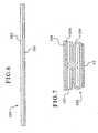
- FIG. 6illustrates in cross section a pull tab forming layer 100, similar to the pull tab forming layer 28 of FIG. 3 , but comprised of a heat seal layer 104 and a foil layer 102.
- This structure 100can provide different and desirable characteristics such as strengthened pull tabs.
- the foil layer 102can serve as a means to conduct heat energy in the heat seal layer 104.
- the foil layer 102can serve as a heat resistant layer and the means to conduct heat energy to the heat seal layer 104.
- Figure 7illustrates in cross section a closure incorporating the pull tab forming layer 100 of Figure 6 .
- This viewis similar to that of Figure 4 , except that in addition to the layer pull tab layer 100, the illustration depicts a system, such as an adhesive system 106, for securing a backing layer 108 to the remainder of the closure.
- a systemsuch as an adhesive system 106
- the foil layerwill covert induction energy to heat energy.
- the heat energywill conduct into the heat seal layer.
- the heat seal layerwill soften and bond to the container.
- FIG 8depicts a cross-sectional view of a closure seal 800 according to the present invention. Similar to the closure seal 10 depicted in FIG. 2 , the closure seal 800 comprises an adhesive material layer 802, a lower seal layer 804 provided on the adhesive material layer 802, and a bonding material layer 806 provided on the lower seal layer 804.
- a pull-tab forming layer 808is bonded to the bonding material layer 806.
- the pull-tab forming layer 808comprises a heat resistant layer 810 and a heat sealable layer 812, which are folded to a shape illustratively depicted in FIG. 8 .
- One having skill in the artwill appreciate that the lengths of the segments of the pull-tab forming layer 808 can be different than as illustratively depicted in FIG. 8 .
- a backing layer 814is provided on the pull-tab forming layer 808.
- the various layers depicted in FIG. 8can comprise materials and provide functionality similar to the similarly-named layers described above with reference to FIGs. 1-7 .
- the heat resistant layer 810 and the heat sealable layer 812can comprise materials that are the same or similar to the materials described with reference to the heat resistant and heat sealable layers depicted in FIGs. 3 and 6 .
- a pair of spaced-apart first folds 902are created wherein the heat sealable layer 812 and heat resistant layer 810 are folded such that the heat sealable layer 812 is folded onto itself 180° at opposite ends of a segment L 3 , so that the folded back heat sealable layer 812 and heat resistant layer 810 continue back in a direction of a central point 904 of the segment L 3 .
- the heat sealable layer 812 and heat resistant layer 810Prior to meeting at the central point 904, and spaced apart at a distance L 4 , the heat sealable layer 812 and heat resistant layer 810 are then folded generally 90° at a pair of second folds 906. Then, the heat sealable layer 812 and heat resistant layer 810 are formed for a distance L 5 perpendicular to the segment L 3 , and folded generally 90° at a third fold 908 in a direction away from the central point 904.
- the distance L 5is large enough that a distance L 6 exists between facing portions of the heat resistant layer 810.
- the heat sealable layer 812 and heat resistant layer 810are then folded 180° at a pair of fourth folds 910 that are spaced apart by a distance L 7 . Accordingly, the heat sealable layer 812 is folded onto itself along the segment L 7 .
- the distance L 7can be the same or different than the distance L 3 .
- the portions of the heat sealable layer 812 and the heat resistant layer 810then terminate at a distance L 8 , which can be the same or different than the distance L 4 .
- the heat sealable layer 812 and heat resistant layer 810can preliminarily be of a predetermined length. Alternatively, the heat sealable layer 812 and heat resistant layer 810 can be cut such that the distance L 8 is created.
- facing portions of the heat resistant layer 810are spaced apart by the distance L 6 , the heat resistant layer 810 does not seal to itself during production. Therefore, a user can pull on first pull-tab portion 816 and the second pull-tab portion 818 of the closure seal 800 without facing portions of the heat resistant layer 810 providing resistance.
- a plurality of closure seals 800can be formed in sheets and punched out or cut, similar to the sheets depicted in FIG. 5 .
Landscapes
- Engineering & Computer Science (AREA)
- Mechanical Engineering (AREA)
- Cartons (AREA)
- Closures For Containers (AREA)
- Packaging Of Annular Or Rod-Shaped Articles, Wearing Apparel, Cassettes, Or The Like (AREA)
- Containers Opened By Tearing Frangible Portions (AREA)
- Containers And Packaging Bodies Having A Special Means To Remove Contents (AREA)
Abstract
Description
- The present invention relates generally to containers having a sealed opening, and more particularly to a closure seal for sealing an opening of a container.
- Packaging for certain types of products, and for bottled liquid products in particular, often require a seal that is both peelable (i.e., easy one-piece removal) and leak-proof and that retains the freshness of the contents of the container. Once opened, the freshness seal will be broken. It is, therefore, desirable that the seal be adequately and securely retained over the opening of the container prior to removal. However, it is also highly desirable that the seal be easily removable by the consumer of the product.
- Many different types of closure seals are known that adequately perform the peeling, leak prevention and freshness seal objectives. Some of these closure seal designs also incorporate some form of structure or device that assists in removal of the seal. Many simple closure seal designs include a tab extending from a peripheral edge of the seal that can be grasped by a user to remove the closure seal from the container. However, it is often difficult for an individual to grip and hold the tab. Moreover, such a tab also requires special die punch equipment to cut the protruding tab. Yet further, the peripherally extending tab can interfere with good sealing due to the need to accommodate the tab in a cap, e.g., by folding over the tab during capping.
- More sophisticated examples of pull-tabs are also known.
- For example,
U.S. Patent Number 5,433,992 discloses a seal construction wherein a multi-layer seal is formed with each of the layers adhering to one another. However, a portion of the seal includes a non-adhered section between two layers. The exposed upper portion of this section of the seal acts as a pull-tab that can be gripped by the user to release the seal from the container. - Selig Sealing Products' own
U.S. Patent No. 5,702,015 discloses a closure seal that also has a pull-tab extending from an upper surface of the seal. The seal disclosed in this patent is formed having a first layer and a second layer of the same material that are coextruded so as to form a single layer with a portion of the layer forming a pull tab. One advantage of this structure is the elimination of possible environmentally sensitive chemicals used in providing adhesive to secure a second layer for the pull tab as is down inU.S. Patent No. 5,43 3, 992 . - One problem with many of these closure seals and pull-tabs are that the pull-tabs are thin and difficult to grasp. Formation of a thicker pull-tab would improve the removability characteristics of the closure seal. However, it is desirable not to increase the number of material layers in order to accomplish this objective because of material and manufacturing cost concerns. Another drawback associated with many pull-tab constructions is that, during the manufacturing process, adhesives and/or other bonding techniques must be applied to the sheet or blank of material intermittently over specified areas in order to accomplish formation of the pull-tab. These specific and precise manufacturing techniques add expense to the manufacturing and design process. A further drawback of many pull-tab designs is that only one pull-tab is available for the consumer to grasp. The pull-tab may be inadvertently partly adhered to another portion of the seal and difficult to initial lift and grasp, or may at least initially be difficult to detect.
U.S. 6,461,714 A1 discloses a seal for a container opening includes a backing layer and a seal layer for connecting to and covering an opening of the container. A pull-tab forming layer is sandwiched between the backing layer and the seal layer. The pull-tab forming layer has a heat sealable surface joined to the backing layer. An opposite heat resistant surface is joined to the seal layer. A hinge is disposed near the centre of the seal that joins the backing layer and the sealed layer wherein the backing layer and at least a portion of the pull-tab forming layer define a pair of pull-tabs extending from the hinge. A method of forming the seal including the pull-tab forming layer and a material blank for forming a plurality of the seals are also described.WO 00/66453 - It is, therefore, one object of the present invention to provide a closure seal for an opening of a container that provides a pair of pull-tabs available to assist in removal of the closure seal from the container. It is another object of the present invention to provide a closure seal that, when the pair of pull-tabs are utilized together, provides a thicker gripping surface making removal, one-piece peel removal in particular, of the closure seal easier. It is a further object of the present invention to provide a closure seal that does not require specialized positioning of adhesives or other bonding techniques applied to or performed on the material strip or blank from which the closure seals are fabricated. It is another object of the present invention to provide a material blank or strip for forming a plurality of the closure seals of the invention. It is a further object of the present invention to provide a method of fabricating closure seals for containers.
- These and other objects, features and advantages are provided by the closure seal, the material blank, and the method of fabricating closure seals of the present invention.
- According to the present invention there is provided a seal for a container opening, the seal comprising:
- a seal layer for connecting to and covering an opening of the container; and
- a pull-tab forming layer bonded to the seal layer, the pull-tab forming layer having a heat resistant surface joined to the seal layer, and a hinge disposed near the centre of the seal, wherein a portion of the pull-tab forming layer defines a pair of opposed pull-tabs extending from the hinge, the heat resistant surface covering a top surface of each of the pull-tabs, a surface of the pull-tabs opposite the top surface, and a portion of the pull-tab forming layer facing the surface of the pull-tabs opposite the top surface.
- In one embodiment, the backing layer is formed from a thermoset polyester material. In another embodiment, the seal layer is an induction aluminum foil layer.
- In one embodiment, the seal layer further includes a bottom surface with a heat activated adhesive carried thereon for attaching the seal to the container.
- In one embodiment, the seal layer is joined to the pull-tab forming layer by a bonding material layer such an adhesive system.
- In one embodiment, the seal layer is joined to the pull-tab forming layer by an extrusion bonding system.
- In one embodiment, the seal layer is joined to the pull-tab forming layer by polyethelene copolymer.
- In one embodiment, the seal layer is joined to the pull-tab forming layer by a dry band system.
- In one embodiment, the heat sealable side of the pull-tab forming layer is formed from a thermoplastic material such as polyethylene.
- In another embodiment, the heat resistant side of the pull-tab forming layer is formed from thermoset polyester.
- In one embodiment, a backing layer is a continuous sheet of thermoplastic polyester material. In another embodiment, the seal layer is a continuous sheet of aluminum foil adhered to the bottom surface of the pull-tab forming layer by an adhesive layer completely covering the bottom surface. In a further embodiment, the first sub-layer of heat sealable material is formed from thermoplastic polyethylene and the second sub-layer of heat resistant material is formed from thermoset polyester.
- In one embodiment, there is provided a seal for a container opening that comprises a seal layer for connecting to and covering an opening of the container. A pull-tab forming layer is bonded to the seal layer, the pull-tab forming layer having a heat resistant surface joined to the seal layer, and a hinge disposed near the center of the seal. A portion of the pull-tab forming layer defines a pair of opposed pull-tabs extending from the hinge, wherein the heat resistant surface covers a top surface of each of the pull-tabs, a surface of the pull-tabs opposite the top surface, and a portion of the pull-tab forming layer facing the surface of the pull-tabs opposite the top surface.
- In one embodiment, the pull-tab forming layer further comprises a heat sealable sublayer and a heat resistant sub-layer joined to one another, wherein the pull-tab forming layer is folded to generally form an 1-shape having an upper horizontal portion and a bottom horizontal portion, wherein the heat resistant sub-layer covers top and bottom outer surfaces of the upper horizontal portion and top and bottom outer surfaces of the bottom horizontal portion.
- In one embodiment, the pull-tab forming layer further comprises an upper heat sealable sub-layer joined to a lower heat resistant sub-layer, wherein the pull-tab forming layer is folded to generally form an I-shape having an upper horizontal portion, a lower horizontal portion, and a vertical portion extending between the upper and lower horizontal portions, wherein the vertical portion defines the hinge, and wherein the upper horizontal portion is bonded to the seal layer.
- In one embodiment, the pull-tab forming layer further comprises: an upper heat sealable sub-layer joined to a lower heat resistant sub-layer, wherein: opposite ends of the pull-tab forming layer are folded about 180° relative to a first linear section of the pull-tab forming layer so that the heat sealable sub-layer of each opposite end is folded onto the heat sealable sub-layer of the first linear section with the opposite ends extending toward one another, the remaining portions of the opposite ends are folded about 90° relative to the first linear section so that the heat sealable sub-layer of a second linear length of each opposite end are spaced apart from one another forming a second linear section, wherein remaining portions of the opposite ends are folded about 90° so that the remaining portions extend away from one another to form a third linear section that is generally parallel to the first linear section, wherein the remaining portions of the opposite ends are folded about 180° relative the third linear section so that the heat sealable sub-layer of each opposite end is folded onto the heat sealable sub-layer of the third linear section with the heat resistant sub-layer material of the last remaining portions joined to the seal layer, the second linear section defines the hinge, and the remaining portions of the opposite ends in the third linear section define the pull-tabs.
- In an embodiment, a material blank for forming a plurality of seals for covering container openings is provided. The blank comprises a seal layer having an upper and a lower surface; and a pull-tab forming layer having a lower surface joined to the upper surface of the seal layer, wherein the pull-tab forming layer includes a heat sealable sub-layer and a heat resistant sub-layer joined to one another, the pull-tab forming layer being folded to generally form an I-shape having an upper horizontal portion and a bottom horizontal portion, and the heat resistant sub-layer covering top and bottom outer surfaces of the upper horizontal portion and top and bottom outer surfaces of the bottom horizontal portion, and wherein the heat sealable sub-layer and the heat resistant sub-layer are folded to form an elongated section.
- In an embodiment, a method of forming a plurality of seals for covering container openings is provided. The method comprises the steps of: providing a seal layer having an upper surface; joining a lower surface of a heat sealable sub-layer with an upper surface of a heat resistant sub-layer; folding the joined heat sealable and heat resistant sub-layers to form at least one elongate section, the section generally having an I-shaped cross section with an upper horizontal portion, a lower horizontal portion, and a vertical hinge portion between the upper horizontal portion and the lower horizontal portion, the heat resistant sub-layer covering a top surface and a bottom surface of each of the upper and lower horizontal portions; securing the pull-tab forming layer to the seal layer by joining the heat resistant sub-layer at the bottom surface of the lower horizontal portion to the upper surface of the seal layer; and punching a plurality of seals having a shape from the secured layers.
- These and other objects, features and advantages of the present invention will become apparent upon a review of the detailed description and accompanying drawing Figures. Particular embodiments of the present invention are disclosed herein only in order to illustrate aspects of the present invention and not in any way to limit the scope of the invention. Changes and modifications can be made to the disclosed embodiments that fall within the scope of the invention.
FIG. 1 illustrates a perspective view of a closure seal which does not form part of the present invention.FIG. 2 illustrates a cross section of a blank or a strip of material layers including a folded pull-tab forming layer for forming a plurality of the closure seals illustrated inFIG. 1 .FIG. 3 illustrates a cross section of the pull-tab forming layer portion of the closure seal prior to folding.FIG. 4 illustrates a cross section of one segment of the pull-tab layer after folding.FIG. 5 illustrates in perspective view, die punch layout nesting on a blank embodying principles of the invention.FIG. 6 illustrates in cross section a pull tab layer including a foil layer.FIG. 7 illustrates in cross section a seal incorporating the pull tab layer ofFIG. 6 .FIG. 8 illustrates in cross section a seal in accordance with methods and devices consistent with the present invention.FIG. 9 illustrates a cross section of the pull-tab layer ofFIG. 8 .- Referring now to the drawings,
FIGS. 1-7 illustrate an embodiment of a closure seal which does not form part of the present invention. FIG. 1 illustrates a perspective view of aclosure seal 10. Theclosure seal 10 includes a pair of pull-tabs sealing section 16 that can be adhered to an opening of a container. The pull-tabs upper surface 18 and 20, respectively, that together define a top surface of theclosure seal 10. The sealingsection 16 includes abottom surface 22 opposite thetop surfaces 18 and 20 of the pull-tabs. Thebottom surface 22 faces and is adhered to the container when theclosure seal 10 is installed.FIG. 2 illustrates a cross-section of material layers that form a sheet or web for making theclosure seal 10 in order to illustrate the particular construction of the closure seals 10. In general, each seal includes anupper backing layer 24, alower seal layer 26, and a tab-forminglayer 28 sandwiched between the backing and seal layers. Abonding material layer 30 is also disposed between thelower seal layer 26 and the pull-tab forming layer 28 in order to join the two layers together. A secondadhesive material layer 32 is provided on the bottom surface of thelower seal layer 26 and defines thebottom surface 22 of theclosure seal 10. Theadhesive material layer 32 is for adhering theclosure seal 10 to the container opening. Each of the particular layers noted above is described in greater detail below, with the pull-tab forming layer 28 described last.- The
upper backing layer 24 can be provided as a thin sheet of material from virtually any suitable heat-resistant material. Examples of such material include thermoset polyester, and the like. Theupper backing layer 24 provides an aesthetic appearance as desired, and can include printed messages to portray visual information to a consumer. Theupper backing layer 24 provides a continuous integral top surface for theclosure seal 10. Theupper backing layer 24 is preferably formed from a resilient material that can be provided in sheet form and that will add strength to the pull-tabs - The
lower seal layer 26 provides the seal function of theclosure seal 10 and is preferably formed of a metal foil that can be heated by induction to seal the container, although other substances or material, such as a plastic film can be utilized. In one embodiment, the seallower layer 26 is an aluminum foil sheet typically having a thickness ranging from about 0.0005 to 0.002 inches. An aluminum foil sheet material is also preferred because thelower seal layer 26 provides a seal that is impermeable to liquid and vapor to prevent moisture and germs or other contaminants from effecting contents within the container. - The
adhesive layer 32 is provided on the bottom surface of theseal layer 26 to adhere theclosure seal 10 to the container opener. Theadhesive layer 32 can be a heat activated adhesive, such as an ionomer that softens when heated and then adheres to a surface when cooled. One such ionomer is marketed under the registered trademark SURLYN® and is available from E.I. DuPont DeNemours & Co. Theadhesive layer 32 can be heated by induction via thelower seal layer 26 or by some other means to soften and adhere the seal to the container as desired. In an alternative embodiment, thelower seal layer 26 can be designated to remain intact when removed from the container. Theadhesive layer 32 can be provided having a weaker bond in order to separate from the container prior to tearing or other damage to thelower seal layer 26. This provides a "clean peel" function whereby theseal 10 is removed without leaving a portion on the container. - The upper surface of the induction or
lower seal layer 26 is adhered to the pull-tab forming layer 28 by abonding layer 30. Again, thisbonding layer 30 can be in the form of an adhesive similar to the heat activated material described above for theadhesive layer 32 or some other suitable adhesive. However, the adhesive must provide a strong enough bond so that the pull-tab forming layer 28 does not separate from the induction foil orlower seal layer 26 when the pull-tabs are utilized to remove theclosure seal 10 from a container. It is therefore preferable that thebonding layer 30 be a fairly significant adhesive, at least providing a superior bond as compared to theadhesive layer 32 attaching the seal to the container. Thebonding layer 30 should sustain the bond between the pull-tab forming layer 28 andlower seal layer 26 beyond when thelower seal layer 26 will tear. - The pull-
tab forming layer 28 is comprised of two separate material layers joined to one another in a suitable manner and then folded and heat bonded to retain the shape of the layer. As illustrated inFIG. 3 , the pull-tab forming layer 28 begins as a flat sheet or strip of material having an upperheat sealable sub-layer 40 adhered to a lower heatresistant sub-layer 42. The two sub-layers typically must be joined prior to creating the folded formation illustrated inFIG. 4 . In one embodiment, theheat sealable sub-layer 40 is formed of a thin thermoplastic material having a thickness in a range of about 0.025 mm (0.001 inches). One example of a suitable material is linear low density polyethylene. One example of a suitable heatresistant sub-layer 42 is a thermoset polyester that can withstand temperatures much higher than theheat sealable layer 40 without melting. - The
lower seal layer 26 will easily tear when the user pulls on the pull-tabs lower seal layer 26 is also durable enough to withstand incidental contact during handling and shipping of the seals and of the sealed containers. Theseal layer 26 can indicate tampering because once the seal is broken or the layer is torn, it cannot be repaired or resealed. FIG. 4 illustrates a portion of the sheet of the pull-tab forming layer 28, defined herein as a foldedsection 48 after undergoing a multiple folding process to complete the final form of thelayer 28.- As best illustrated in
FIG. 2 , ideally, a plurality of identical foldedsections 48 are formed adjacent one another from the unfoldedlayer 28. Each of thesections 48 defines one strip of the pull-tab forming layer for forming individual closure seals 10. The folded form and the method are described for only one of thesections 48. The form and method is then repeated multiple times in order to create a sheet or web of the pull-tab forming layer 28 for producing multiple closure seals 10 in a grid. However, such a continuous folding method is difficult and the invention preferably, at least initially, is practiced forming single folded strips, i.e., a long strip with onesection 48. This is essentially as shown inFIG. 4 . - As shown in
FIG. 4 , a pair of spaced apart folds indicated generally at 50 are created wherein theheat sealable sub-layer 40 is folded onto itself 180° at opposite ends of a segment length L1, so that the material continues back over the length or segment. When the opposing ends of thelayer 28 meet at the center of the segment L1, the material is then folded 90° vertically at a pair ofsecond folds 52 so that the heat sealable material is still folded onto itself but extending vertically. A third fold indicated generally at 54 is then created in each segment of thelayer 28 wherein the fold is generally 90° and the segments of thelayer 28 extend opposed to one another. In this manner, the single section of thelayer 28 generally has an I-shaped configuration. Thesection 48 of thelayer 28 includes an upperhorizontal segment 56, a vertical segment 58 defined by the length L2, and a lower horizontal segment 60 defined by the length L1. Heat can then be applied to the foldedlayer 28 so that the folded segments of theheat sealable layer 40 in contact with one another are sealed together. The strip of material is folded multiple times in the same manner to define a plurality of separate parallel sections of the pull-tab forming layer 28. The upperhorizontal segments 56 are illustrated integrally connected to adjacent foldedsections 48 of thelayer 28 until theindividual seals 10 are punched or cut out. - As illustrated in
Figure 5 , as a practical matter, diepunch layouts 500 are nested to minimize waste. Thus, along a given longitudinal direction, the punch outs overlap by the difference between broken lines C' and C", which represent longitudinally extending tangents to the die punch layouts in adjacent longitudinal rows or columns. However, this does not affect overall form or function of a given seal with the inventive pull tap structure. - In one embodiment, each of the
sections 48 can include the identical size and shape to be used in a blank for forming a plurality of identical closure seals 10. Alternatively, one or more of the separate sections of thelayer 28 can include various segment sizes to provide sections having different shapes for producing closure seals 10 of different size and/or configuration from the same sheet of material. - The strip or sheet of folded and formed pull-
tab forming layer 28 is then further processed to add thebacking layer 24. In one embodiment, thebacking layer 24 is secured to the heat sealable side of thelayer 28 defined by the adjacent upperhorizontal segments 56 by any of various suitable methods including: (1) applying heat to bond theheat sealable sub-layer 40 to itself and to thebacking layer 24; (2) an adhesive system; (3) a co-extrusion system, to mention a few. Thelower seal layer 26 is adhered to the heat resistant side of thelayer 28 defined by the adjacent horizontal segments 60 utilizing the above-describedbonding layer 30. Theseal adhesive layer 32 is applied to thelower seal layer 26 before or after adhering thelower seal layer 26 to the pull-tab forming layer 28. FIG. 2 illustrates a portion of a sheet or blank 70 of the folded and adhered material layers that ideally is utilized to produce a plurality of the closure seals 10.Individual seals 10 are cut or punched from the blank in rows and columns depending upon the length of the strip of material and the number of foldedsections 48. The cuts would be formed where noted by the lines C inFIG. 2 to separate each of the individual lower horizontal segments 60 of the separate sections of the formedlayer 28. The separation would not bisect the continuous upper surface of the formedlayer 28 to produce the upperhorizontal sections 56 due to the die punch layout nesting mentioned above.- The pull-tabs are not adhered in any way to the
seal layer 26, thebonding layer 30 or any other portion of the pull-tab forming layer 28 during any of the adhesion processes or techniques. This is because the heatresistant sub-layer 42 is on the bottom surface of thehorizontal segments 56 of each section of the foldedlayer 28, on the outer side surfaces of the vertical segments 58, and on the bottom and top surfaces of the lower horizontal segments 60. The vertical segments 58 each define a hinge about which the pull-tabs - Each
individual closure seal 10 as illustrated inFIG. 1 is placed on an opening of a bottle or container. Induction heating can be utilized via the induction foil orlower seal layer 26 to bond the closure seal via theadhesive layer 32 to cover the opening of the container. The pull-tabs tabs seal layer 26. Alternatively, a consumer can grasp both of the pull-tabs backing layer 24 on opposite sides of the hinge abut one another. This produces a thicker pull-tab that is easier to grasp for many consumers. The consumer can then pull the combined pull-tabs FIG. 1 illustrates around closure seal 10 for attaching to a container.having a round opening into the container. As will be apparent to those skilled in the art, the size, shape and contour of the closure seal can vary considerably depending upon the size, shape and contour of the intended container opening.FIG. 6 illustrates in cross section a pulltab forming layer 100, similar to the pulltab forming layer 28 ofFIG. 3 , but comprised of aheat seal layer 104 and afoil layer 102. Thisstructure 100 can provide different and desirable characteristics such as strengthened pull tabs. Further, thefoil layer 102 can serve as a means to conduct heat energy in theheat seal layer 104. Essentially, then thefoil layer 102 can serve as a heat resistant layer and the means to conduct heat energy to theheat seal layer 104.Figure 7 illustrates in cross section a closure incorporating the pulltab forming layer 100 ofFigure 6 . This view is similar to that ofFigure 4 , except that in addition to the layerpull tab layer 100, the illustration depicts a system, such as anadhesive system 106, for securing abacking layer 108 to the remainder of the closure.- As the entire structure passes through an induction energy field, the foil layer will covert induction energy to heat energy. The heat energy will conduct into the heat seal layer. In turn the heat seal layer will soften and bond to the container.
- At the same time, the portion of the
foil layer 102 which is folded back against itself, where the pull tabs are formed, will not adhere to itself and therefore will allow the tabbed portion to operate as a hinge. - Referring to
FIG. 8, FIG 8 depicts a cross-sectional view of aclosure seal 800 according to the present invention. Similar to theclosure seal 10 depicted inFIG. 2 , theclosure seal 800 comprises anadhesive material layer 802, alower seal layer 804 provided on theadhesive material layer 802, and abonding material layer 806 provided on thelower seal layer 804. - A pull-
tab forming layer 808 is bonded to thebonding material layer 806. The pull-tab forming layer 808 comprises a heatresistant layer 810 and aheat sealable layer 812, which are folded to a shape illustratively depicted inFIG. 8 . One having skill in the art will appreciate that the lengths of the segments of the pull-tab forming layer 808 can be different than as illustratively depicted inFIG. 8 . Abacking layer 814 is provided on the pull-tab forming layer 808. - The various layers depicted in
FIG. 8 can comprise materials and provide functionality similar to the similarly-named layers described above with reference toFIGs. 1-7 . For example, the heatresistant layer 810 and theheat sealable layer 812 can comprise materials that are the same or similar to the materials described with reference to the heat resistant and heat sealable layers depicted inFIGs. 3 and6 . - Referring to
FIG. 9 , to produce the pull-tab forming layer 808, a pair of spaced-apart first folds 902 are created wherein theheat sealable layer 812 and heatresistant layer 810 are folded such that theheat sealable layer 812 is folded onto itself 180° at opposite ends of a segment L3, so that the folded backheat sealable layer 812 and heatresistant layer 810 continue back in a direction of acentral point 904 of the segment L3. - Prior to meeting at the
central point 904, and spaced apart at a distance L4, theheat sealable layer 812 and heatresistant layer 810 are then folded generally 90° at a pair of second folds 906. Then, theheat sealable layer 812 and heatresistant layer 810 are formed for a distance L5 perpendicular to the segment L3, and folded generally 90° at athird fold 908 in a direction away from thecentral point 904. The distance L5 is large enough that a distance L6 exists between facing portions of the heatresistant layer 810. - The
heat sealable layer 812 and heatresistant layer 810 are then folded 180° at a pair offourth folds 910 that are spaced apart by a distance L7. Accordingly, theheat sealable layer 812 is folded onto itself along the segment L7. The distance L7 can be the same or different than the distance L3. The portions of theheat sealable layer 812 and the heatresistant layer 810 then terminate at a distance L8, which can be the same or different than the distance L4. - To form the pull-
tab forming layer 808, theheat sealable layer 812 and heatresistant layer 810 can preliminarily be of a predetermined length. Alternatively, theheat sealable layer 812 and heatresistant layer 810 can be cut such that the distance L8 is created. - Referring back to
FIG. 8 , since facing portions of the heatresistant layer 810 are spaced apart by the distance L6, the heatresistant layer 810 does not seal to itself during production. Therefore, a user can pull on first pull-tab portion 816 and the second pull-tab portion 818 of theclosure seal 800 without facing portions of the heatresistant layer 810 providing resistance. - Similar to the
closure seal 10 described with reference toFIG. 2 , a plurality of closure seals 800 can be formed in sheets and punched out or cut, similar to the sheets depicted inFIG. 5 . - The above material examples described for fabricating each layer can also vary without departing from the spirit and scope of the present invention. Many other changes and modifications can be made to the described embodiments. These changes and modifications are intended to fall within the scope of the present invention. The described embodiments are provided only to illustrate aspects of the present invention and not intended to limit the scope of the invention. The invention is only to be limited by the scope of the appended claims.
Claims (23)
- A seal (800) for a container opening, the seal comprising:a seal layer (804) for connecting to and covering an opening of the container; anda pull-tab forming layer (808) bonded to the seal layer (804), the pull-tab forming layer (808) having a heat resistant surface (810) joined to the seal layer (804), and a hinge (906, 908) disposed near the centre (904) of the seal, wherein a portion of the pull-tab forming layer defines a pair of opposed pull-tabs extending from the hinge (906, 908),characterised in that the heat resistant surface (810) covers a top surface of each of the pull-tabs (816, 818), a surface of the pull-tabs opposite the top surface, and a portion of the pull-tab forming layer facing the surface of the pull-tabs opposite the top surface.
- A seal according to claim 1, wherein the pull-tab forming layer (808) further comprises:a heat sealable sub-layer (812) and a heat resistant sub-layer (810) joined to one another, wherein the pull-tab forming layer (808) is folded to generally form an I-shape having an upper horizontal portion and a bottom horizontal portion, wherein the heat resistant sub-layer (810) covers top and bottom outer surfaces of the upper horizontal portion and top and bottom outer surfaces of the bottom horizontal portion.
- A seal according to claim 1, wherein the pull-tab forming layer (808) further comprises:an upper heat sealable sub-layer (812) joined to a lower heat resistant sub-layer (810), wherein the pull-tab forming layer is folded to generally form an I-shape having an upper horizontal portion, a lower horizontal portion, and a vertical portion extending between the upper and lower horizontal portions, wherein the vertical portion defines the hinge, and wherein the upper horizontal portion is bonded to the seal layer.
- A seal according to claim 1, wherein the pull-tab forming layer (808) further comprises:an upper heat sealable sub-layer (812) joined to a lower heat resistant sub-layer (810), wherein:opposite ends of the pull-tab forming layer are folded about 180° relative to a first linear section of the pull-tab forming layer so that the heat sealable sub-layer (812) of each opposite end is folded onto the heat sealable sub-layer (812) of the first linear section with the opposite ends extending toward one another,the remaining portions of the opposite ends are folded about 90° relative to the first linear section so that the heat sealable sub-layer (812) of a second linear length of each opposite end are spaced apart from one another forming a second linear section,remaining portions of the opposite ends are folded about 90° so that the remaining portions extend away from one another to form a third linear section that is generally parallel to the first linear section,the remaining portions of the opposite ends are folded about 180° relative the third linear section so that the heat sealable sub-layer (812) of each opposite end is folded onto the heat sealable sub-layer (812) of the third linear section with the heat resistant sub-layer material of the last remaining portions joined to the seal layer,the second linear section defines the hinge, andthe remaining portions of the opposite ends in the third linear section define the pull-tabs.
- A seal according to any preceding claim, further comprising a backing layer (814) formed to a side of the pull-tab forming layer (808) opposite the seal layer (804).
- A seal according to claim 5, wherein the backing layer (814) is formed from a thermoset polyester material.
- A seal according to any preceding claim, wherein the seal layer (814) is an induction aluminium foil layer.
- A seal according to any preceding claim, wherein the seal layer (804) further includes a bottom surface having a heat activated adhesive (802) carried thereon for attaching the seal to the container.
- A seal according to any preceding claim, wherein the seal layer (804) is joined to the pull-tab forming layer (808) by a bonding material layer (806).
- A seal according to claim 9, wherein the bonding material layer (806) comprises a polyethylene copolymer material.
- A seal according to any one of claims 2-4, wherein the heat sealable sub-layer (812) comprises a thermoplastic material.
- A seal according to any preceding claim, wherein the heat resistant surface (810) of the pull-tab forming layer (808) comprises a thermoset polyester material.
- A material blank for forming a plurality of seals for covering container openings, the blank comprising:a seal layer (804) having an upper and a lower surface; anda pull-tab forming layer (808) having a lower surface joined to the upper surface of the seal layer (804), wherein the pull-tab forming layer (808) includes a heat sealable sub-layer (812) and a heat resistant sub-layer (810) joined to one another, the pull-tab forming layer (808) being folded to generally form an I-shape having an upper horizontal portion and a bottom horizontal portion, and the heat resistant sub-layer (810) covering top and bottom outer surfaces of the upper horizontal portion and a top and bottom outer surfaces of the bottom horizontal portion, and wherein the heat sealable sub-layer (812) and the heat resistant sub-layer (810) are folded to form an elongated section.
- A material blank according to claim 13, wherein the pull-tab forming layer (808) comprises a plurality of pull-tab forming layers.
- A material blank according to claim 14, wherein the seal layer (804) is a contiguous sheet having the plurality of pull-tab forming layers joined thereon.
- A material blank according to any one of claims 13-15, wherein the seal layer (804) is joined to the pull-tab forming layer (808) by an adhesive layer (806).
- A material blank according to any one of claims 13-16, wherein the heat sealable sub-layer (812) comprises thermoplastic polyethylene, and wherein the heat resistant sub-layer (810) comprises thermoset polyester.
- A material blank according to any one ofclaims 13-17, further comprises a backing layer (814) joined to a surface of the pull-tab forming layer (808) opposite the seal layer (804).
- A method of forming a plurality of seals (800) for covering container openings, the method comprising the steps of:providing a seal layer (804) having an upper surface;joining a lower surface of a heat sealable sub-layer (812) with an upper surface of a heat resistant sub-layer (810);folding the joined heat sealable and heat resistant sub-layers (808) to form at least one elongate section, the section generally having an I-shaped cross section with an upper horizontal portion, a lower horizontal portion, and a vertical hinge portion (906, 908) between the upper horizontal portion and the lower horizontal portion, the heat resistant sub-layer (810) covering a top surface and a bottom surface of each of the upper and lower horizontal portions;securing the pull-tab forming layer (808) to the seal layer (804) by joining the heat resistant sub-layer (810) at the bottom surface of the lower horizontal portion to the upper surface of the seal layer (804); andpunching a plurality of seals (800) having a shape from the secured layers.
- A method according to claim 19, further comprising the step of:joining a backing layer (814) to the top surface of the upper horizontal portion.
- A method according to claim 19 or claim 20, wherein the step of securing the seal layer (804) and the pull-tab forming layer (808) further includes applying a bonding layer (806) over either the upper surface of the seal layer (804) or the bottom surface of the lower horizontal portion.
- A method according to claim 20, wherein the step of joining the backing layer (814) to the pull-tab forming layer (808) comprises dry bonding the layers together.
- A method according to claim 20, wherein the step of joining the backing layer (814) to the pull-tab forming layer (808) comprises extrusion bonding the layers together.
Priority Applications (1)
| Application Number | Priority Date | Filing Date | Title |
|---|---|---|---|
| PL04751996TPL1628887T3 (en) | 2003-05-12 | 2004-05-12 | Closure seal for a container |
Applications Claiming Priority (2)
| Application Number | Priority Date | Filing Date | Title |
|---|---|---|---|
| US10/436,512US6986930B2 (en) | 2000-10-20 | 2003-05-12 | Closure seal for a container |
| PCT/US2004/014852WO2004101368A2 (en) | 2003-05-12 | 2004-05-12 | Closure seal for a container |
Publications (3)
| Publication Number | Publication Date |
|---|---|
| EP1628887A2 EP1628887A2 (en) | 2006-03-01 |
| EP1628887A4 EP1628887A4 (en) | 2008-09-03 |
| EP1628887B1true EP1628887B1 (en) | 2010-09-01 |
Family
ID=33449711
Family Applications (1)
| Application Number | Title | Priority Date | Filing Date |
|---|---|---|---|
| EP04751996AExpired - LifetimeEP1628887B1 (en) | 2003-05-12 | 2004-05-12 | Closure seal for a container |
Country Status (8)
| Country | Link |
|---|---|
| US (2) | US6986930B2 (en) |
| EP (1) | EP1628887B1 (en) |
| AT (1) | ATE479627T1 (en) |
| CA (1) | CA2525420C (en) |
| DE (1) | DE602004028929D1 (en) |
| ES (1) | ES2351977T3 (en) |
| PL (1) | PL1628887T3 (en) |
| WO (1) | WO2004101368A2 (en) |
Families Citing this family (29)
| Publication number | Priority date | Publication date | Assignee | Title |
|---|---|---|---|---|
| JP2007145363A (en)* | 2005-11-28 | 2007-06-14 | Q P Corp | Seal and manufacturing method thereof, and container with seal and manufacturing method thereof |
| US20080092475A1 (en)* | 2006-10-04 | 2008-04-24 | J.H. Fenner & Co. Ltd | Fire resistant mine door sealing system |
| JP5216332B2 (en)* | 2008-01-09 | 2013-06-19 | 藤森工業株式会社 | Inner seal material and method for sealing a container with a cap using the same |
| JP4987532B2 (en)* | 2007-03-28 | 2012-07-25 | 藤森工業株式会社 | Manufacturing method of sealing film and manufacturing method of container with inner seal |
| EP2130781B1 (en)* | 2007-03-28 | 2017-08-16 | Fujimori Kogyo Co., Ltd. | Method of and apparatus for manufacturing seal film |
| JP5156402B2 (en)* | 2008-01-09 | 2013-03-06 | 藤森工業株式会社 | Seal film manufacturing method and manufacturing apparatus |
| JP5210641B2 (en)* | 2008-01-08 | 2013-06-12 | 藤森工業株式会社 | Manufacturing method of sealing film |
| US8146781B2 (en) | 2007-08-09 | 2012-04-03 | Huhtamaki, Inc. | Dispenser for viscous condiments |
| EP2183106B1 (en)* | 2007-08-24 | 2016-10-12 | Selig Sealing Products, Inc. | Multi-purpose covering for hygienically covering a container top |
| BRPI0905728A2 (en)* | 2008-01-18 | 2015-07-14 | Tab It Llc | "sealing member formed with a pull-open tab and sealed container" |
| US9090151B2 (en)* | 2010-09-13 | 2015-07-28 | Ultrafab, Inc. | System, method and apparatus for producing weatherstrip containing profiles of different shape and weatherstrips for use therewith |
| US9028963B2 (en) | 2012-09-05 | 2015-05-12 | Selig Sealing Products, Inc. | Tamper evident tabbed sealing member having a foamed polymer layer |
| CN103247233B (en)* | 2013-04-28 | 2015-09-23 | 京东方科技集团股份有限公司 | Flexible base, board, display device and attach the method for electron device on flexible substrates |
| KR101496338B1 (en)* | 2013-05-13 | 2015-03-02 | 주식회사 모성 | Laminate structure for container sealing |
| KR101407569B1 (en)* | 2014-01-15 | 2014-07-02 | 주식회사 씰앤팩 | Vassel sealing member and producing method therefor |
| WO2015119988A1 (en) | 2014-02-05 | 2015-08-13 | Selig Sealing Products, Inc. | Dual aluminum tamper indicating tabbed sealing member |
| EP3786082B1 (en) | 2015-03-03 | 2021-12-22 | Selig Sealing Products, Inc. | Tabbed seal |
| WO2017069609A1 (en)* | 2015-10-22 | 2017-04-27 | N.V. Nutricia | Sealing foil with pull tab |
| US11787153B2 (en) | 2016-04-06 | 2023-10-17 | Tekni-Plex, Inc. | Thermally laminated tab liner |
| US11148400B2 (en)* | 2016-04-06 | 2021-10-19 | Tekni-Plex, Inc. | Thermally laminated tab liner |
| WO2018081533A1 (en) | 2016-10-28 | 2018-05-03 | Selig Sealing Products, Inc. | Sealing member for use with fat containing compositions |
| CN109863093B (en) | 2016-10-28 | 2021-11-26 | 赛利格密封产品公司 | Single aluminium tamper-indicating pull-tab type sealing member |
| US11866242B2 (en) | 2016-10-31 | 2024-01-09 | Selig Sealing Products, Inc. | Tabbed inner seal |
| CN108485003A (en)* | 2018-02-12 | 2018-09-04 | 中国北方车辆研究所 | A kind of high pressure of multiple leak oil is hinged sealing mechanism |
| US11724863B2 (en) | 2018-07-09 | 2023-08-15 | Selig Sealing Products, Inc. | Tabbed seal with oversized tab |
| US11254481B2 (en) | 2018-09-11 | 2022-02-22 | Selig Sealing Products, Inc. | Enhancements for tabbed seal |
| US11390428B2 (en)* | 2019-08-13 | 2022-07-19 | Sealtech Llc | User-friendly tamper-resistant/tamper-evident container-seal system for containers of consumer goods and methods of use |
| MX2022006462A (en)* | 2019-11-29 | 2022-07-13 | Selig Sealing Products Inc | TAB SEAL WITHOUT FOIL. |
| US12377630B2 (en) | 2020-05-29 | 2025-08-05 | Selig Sealing Products, Inc. | Dispensing liner |
Family Cites Families (9)
| Publication number | Priority date | Publication date | Assignee | Title |
|---|---|---|---|---|
| US4000838A (en)* | 1972-09-29 | 1977-01-04 | Clayton Bogert | Spout forming means for containers |
| CA1336708C (en) | 1987-09-09 | 1995-08-15 | Michael P. Galda | Sealing member for a container |
| US5226281A (en)* | 1989-02-27 | 1993-07-13 | Minnesota Mining And Manufacturing Company | Z-tab innerseal for a container and method of application |
| US5433982A (en)* | 1990-11-14 | 1995-07-18 | Dai Nippon Printing Co., Ltd. | Composite container having barrier property |
| US5702015A (en)* | 1994-05-04 | 1997-12-30 | Selig Sealing Products, Inc. | Closure seal for container |
| US5607384A (en) | 1995-07-12 | 1997-03-04 | Caparros; Rudolph | Apparatus and process for safely containing and delivering hazardous fluid substances from supply cylinders |
| AU6337096A (en) | 1995-07-12 | 1997-02-10 | Minnesota Mining And Manufacturing Company | Top-tabbed sealing member for a container and method of making same |
| DE19920586A1 (en)* | 1999-05-04 | 2000-11-16 | Alfelder Kunststoffw Meyer H | Sealing disc and film composite for a container closure |
| US6461714B1 (en) | 2000-10-20 | 2002-10-08 | Selig Sealing Products, Inc. | Closure seal for a container |
- 2003
- 2003-05-12USUS10/436,512patent/US6986930B2/ennot_activeExpired - Lifetime
- 2004
- 2004-05-12ESES04751996Tpatent/ES2351977T3/ennot_activeExpired - Lifetime
- 2004-05-12CACA2525420Apatent/CA2525420C/ennot_activeExpired - Fee Related
- 2004-05-12EPEP04751996Apatent/EP1628887B1/ennot_activeExpired - Lifetime
- 2004-05-12WOPCT/US2004/014852patent/WO2004101368A2/enactiveApplication Filing
- 2004-05-12PLPL04751996Tpatent/PL1628887T3/enunknown
- 2004-05-12DEDE602004028929Tpatent/DE602004028929D1/ennot_activeExpired - Lifetime
- 2004-05-12ATAT04751996Tpatent/ATE479627T1/ennot_activeIP Right Cessation
- 2005
- 2005-11-17USUS11/281,114patent/US7419559B2/ennot_activeExpired - Fee Related
Also Published As
| Publication number | Publication date |
|---|---|
| ES2351977T3 (en) | 2011-02-14 |
| CA2525420C (en) | 2011-05-03 |
| EP1628887A2 (en) | 2006-03-01 |
| CA2525420A1 (en) | 2004-11-25 |
| EP1628887A4 (en) | 2008-09-03 |
| WO2004101368A2 (en) | 2004-11-25 |
| DE602004028929D1 (en) | 2010-10-14 |
| PL1628887T3 (en) | 2011-02-28 |
| US7419559B2 (en) | 2008-09-02 |
| US20040071934A1 (en) | 2004-04-15 |
| WO2004101368A3 (en) | 2005-04-21 |
| ATE479627T1 (en) | 2010-09-15 |
| US6986930B2 (en) | 2006-01-17 |
| US20060068163A1 (en) | 2006-03-30 |
Similar Documents
| Publication | Publication Date | Title |
|---|---|---|
| EP1628887B1 (en) | Closure seal for a container | |
| EP1199253B1 (en) | Closure seal for a container | |
| US8517201B2 (en) | Heat-sealable inner seal for sealing a container | |
| US5975304A (en) | Sealed containers with tabs and method of making the same | |
| EP2571782B1 (en) | Easy open flexible film packaging products and methods of manufacture | |
| US9656783B2 (en) | Reclosable flexible packaging and methods for manufacturing same | |
| US10279953B2 (en) | Container seal | |
| MX2007004198A (en) | Membrane closure for container. | |
| JP6829500B2 (en) | High-frequency induction heating container that can be bonded on both sides A sealed body, a compact cosmetic container with a tamper function to which it is applied, and a container with a flip cap with a tamper function to which it is applied. | |
| US20120043324A1 (en) | Container with Reduced, Peel-Off-Force Tear Configuration | |
| US20230348157A1 (en) | Tabbed Seal With Oversized Tab | |
| EP3365173B1 (en) | Sealing foil with pull tab | |
| CA2628994A1 (en) | Container lid formed as a laminate having a built-in opening feature, and container incorporating same | |
| US12172798B2 (en) | Peelable resealable membrane for containers | |
| JP6060503B2 (en) | Lid material and packaging container using the lid material | |
| KR101901655B1 (en) | The flip-cap container with tamper-evident of application of the double-sided adhesive incorporation container of an induction heating apparatus with high frequency | |
| NZ741858B2 (en) | Sealing foil with pull tab | |
| MXPA99007797A (en) | Sealed containers with tabs and method to prepare |
Legal Events
| Date | Code | Title | Description |
|---|---|---|---|
| PUAI | Public reference made under article 153(3) epc to a published international application that has entered the european phase | Free format text:ORIGINAL CODE: 0009012 | |
| 17P | Request for examination filed | Effective date:20051209 | |
| AK | Designated contracting states | Kind code of ref document:A2 Designated state(s):AT BE BG CH CY CZ DE DK EE ES FI FR GB GR HU IE IT LI LU MC NL PL PT RO SE SI SK TR | |
| DAX | Request for extension of the european patent (deleted) | ||
| A4 | Supplementary search report drawn up and despatched | Effective date:20080801 | |
| 17Q | First examination report despatched | Effective date:20081114 | |
| RIC1 | Information provided on ipc code assigned before grant | Ipc:B67D 7/12 20100101AFI20100113BHEP | |
| GRAP | Despatch of communication of intention to grant a patent | Free format text:ORIGINAL CODE: EPIDOSNIGR1 | |
| GRAS | Grant fee paid | Free format text:ORIGINAL CODE: EPIDOSNIGR3 | |
| GRAA | (expected) grant | Free format text:ORIGINAL CODE: 0009210 | |
| AK | Designated contracting states | Kind code of ref document:B1 Designated state(s):AT BE BG CH CY CZ DE DK EE ES FI FR GB GR HU IE IT LI LU MC NL PL PT RO SE SI SK TR | |
| REG | Reference to a national code | Ref country code:GB Ref legal event code:FG4D | |
| REG | Reference to a national code | Ref country code:CH Ref legal event code:EP | |
| REG | Reference to a national code | Ref country code:IE Ref legal event code:FG4D | |
| REF | Corresponds to: | Ref document number:602004028929 Country of ref document:DE Date of ref document:20101014 Kind code of ref document:P | |
| REG | Reference to a national code | Ref country code:CH Ref legal event code:NV Representative=s name:KELLER & PARTNER PATENTANWAELTE AG | |
| REG | Reference to a national code | Ref country code:NL Ref legal event code:VDEP Effective date:20100901 | |
| PG25 | Lapsed in a contracting state [announced via postgrant information from national office to epo] | Ref country code:AT Free format text:LAPSE BECAUSE OF FAILURE TO SUBMIT A TRANSLATION OF THE DESCRIPTION OR TO PAY THE FEE WITHIN THE PRESCRIBED TIME-LIMIT Effective date:20100901 Ref country code:FI Free format text:LAPSE BECAUSE OF FAILURE TO SUBMIT A TRANSLATION OF THE DESCRIPTION OR TO PAY THE FEE WITHIN THE PRESCRIBED TIME-LIMIT Effective date:20100901 | |
| REG | Reference to a national code | Ref country code:ES Ref legal event code:FG2A Effective date:20110202 | |
| PG25 | Lapsed in a contracting state [announced via postgrant information from national office to epo] | Ref country code:SI Free format text:LAPSE BECAUSE OF FAILURE TO SUBMIT A TRANSLATION OF THE DESCRIPTION OR TO PAY THE FEE WITHIN THE PRESCRIBED TIME-LIMIT Effective date:20100901 Ref country code:CY Free format text:LAPSE BECAUSE OF FAILURE TO SUBMIT A TRANSLATION OF THE DESCRIPTION OR TO PAY THE FEE WITHIN THE PRESCRIBED TIME-LIMIT Effective date:20100901 | |
| REG | Reference to a national code | Ref country code:PL Ref legal event code:T3 | |
| PG25 | Lapsed in a contracting state [announced via postgrant information from national office to epo] | Ref country code:SE Free format text:LAPSE BECAUSE OF FAILURE TO SUBMIT A TRANSLATION OF THE DESCRIPTION OR TO PAY THE FEE WITHIN THE PRESCRIBED TIME-LIMIT Effective date:20100901 Ref country code:NL Free format text:LAPSE BECAUSE OF FAILURE TO SUBMIT A TRANSLATION OF THE DESCRIPTION OR TO PAY THE FEE WITHIN THE PRESCRIBED TIME-LIMIT Effective date:20100901 Ref country code:GR Free format text:LAPSE BECAUSE OF FAILURE TO SUBMIT A TRANSLATION OF THE DESCRIPTION OR TO PAY THE FEE WITHIN THE PRESCRIBED TIME-LIMIT Effective date:20101202 | |
| PG25 | Lapsed in a contracting state [announced via postgrant information from national office to epo] | Ref country code:RO Free format text:LAPSE BECAUSE OF FAILURE TO SUBMIT A TRANSLATION OF THE DESCRIPTION OR TO PAY THE FEE WITHIN THE PRESCRIBED TIME-LIMIT Effective date:20100901 Ref country code:SK Free format text:LAPSE BECAUSE OF FAILURE TO SUBMIT A TRANSLATION OF THE DESCRIPTION OR TO PAY THE FEE WITHIN THE PRESCRIBED TIME-LIMIT Effective date:20100901 Ref country code:CZ Free format text:LAPSE BECAUSE OF FAILURE TO SUBMIT A TRANSLATION OF THE DESCRIPTION OR TO PAY THE FEE WITHIN THE PRESCRIBED TIME-LIMIT Effective date:20100901 Ref country code:PT Free format text:LAPSE BECAUSE OF FAILURE TO SUBMIT A TRANSLATION OF THE DESCRIPTION OR TO PAY THE FEE WITHIN THE PRESCRIBED TIME-LIMIT Effective date:20110103 Ref country code:EE Free format text:LAPSE BECAUSE OF FAILURE TO SUBMIT A TRANSLATION OF THE DESCRIPTION OR TO PAY THE FEE WITHIN THE PRESCRIBED TIME-LIMIT Effective date:20100901 | |
| PLBE | No opposition filed within time limit | Free format text:ORIGINAL CODE: 0009261 | |
| STAA | Information on the status of an ep patent application or granted ep patent | Free format text:STATUS: NO OPPOSITION FILED WITHIN TIME LIMIT | |
| 26N | No opposition filed | Effective date:20110606 | |
| PG25 | Lapsed in a contracting state [announced via postgrant information from national office to epo] | Ref country code:DK Free format text:LAPSE BECAUSE OF FAILURE TO SUBMIT A TRANSLATION OF THE DESCRIPTION OR TO PAY THE FEE WITHIN THE PRESCRIBED TIME-LIMIT Effective date:20100901 | |
| REG | Reference to a national code | Ref country code:DE Ref legal event code:R097 Ref document number:602004028929 Country of ref document:DE Effective date:20110606 | |
| PG25 | Lapsed in a contracting state [announced via postgrant information from national office to epo] | Ref country code:MC Free format text:LAPSE BECAUSE OF NON-PAYMENT OF DUE FEES Effective date:20110531 | |
| REG | Reference to a national code | Ref country code:IE Ref legal event code:MM4A | |
| PG25 | Lapsed in a contracting state [announced via postgrant information from national office to epo] | Ref country code:IE Free format text:LAPSE BECAUSE OF NON-PAYMENT OF DUE FEES Effective date:20110512 | |
| PGFP | Annual fee paid to national office [announced via postgrant information from national office to epo] | Ref country code:DE Payment date:20120529 Year of fee payment:9 Ref country code:CH Payment date:20120525 Year of fee payment:9 | |
| PGFP | Annual fee paid to national office [announced via postgrant information from national office to epo] | Ref country code:GB Payment date:20120525 Year of fee payment:9 Ref country code:FR Payment date:20120607 Year of fee payment:9 Ref country code:PL Payment date:20120420 Year of fee payment:9 Ref country code:BE Payment date:20120529 Year of fee payment:9 | |
| PGFP | Annual fee paid to national office [announced via postgrant information from national office to epo] | Ref country code:IT Payment date:20120523 Year of fee payment:9 | |
| PGFP | Annual fee paid to national office [announced via postgrant information from national office to epo] | Ref country code:ES Payment date:20120528 Year of fee payment:9 | |
| PG25 | Lapsed in a contracting state [announced via postgrant information from national office to epo] | Ref country code:LU Free format text:LAPSE BECAUSE OF NON-PAYMENT OF DUE FEES Effective date:20110512 | |
| PG25 | Lapsed in a contracting state [announced via postgrant information from national office to epo] | Ref country code:TR Free format text:LAPSE BECAUSE OF FAILURE TO SUBMIT A TRANSLATION OF THE DESCRIPTION OR TO PAY THE FEE WITHIN THE PRESCRIBED TIME-LIMIT Effective date:20100901 Ref country code:BG Free format text:LAPSE BECAUSE OF FAILURE TO SUBMIT A TRANSLATION OF THE DESCRIPTION OR TO PAY THE FEE WITHIN THE PRESCRIBED TIME-LIMIT Effective date:20101201 | |
| PG25 | Lapsed in a contracting state [announced via postgrant information from national office to epo] | Ref country code:HU Free format text:LAPSE BECAUSE OF FAILURE TO SUBMIT A TRANSLATION OF THE DESCRIPTION OR TO PAY THE FEE WITHIN THE PRESCRIBED TIME-LIMIT Effective date:20100901 | |
| BERE | Be: lapsed | Owner name:SELIG SEALING PRODUCTS, INC. Effective date:20130531 | |
| REG | Reference to a national code | Ref country code:CH Ref legal event code:PL | |
| GBPC | Gb: european patent ceased through non-payment of renewal fee | Effective date:20130512 | |
| PG25 | Lapsed in a contracting state [announced via postgrant information from national office to epo] | Ref country code:DE Free format text:LAPSE BECAUSE OF NON-PAYMENT OF DUE FEES Effective date:20131203 Ref country code:LI Free format text:LAPSE BECAUSE OF NON-PAYMENT OF DUE FEES Effective date:20130531 Ref country code:CH Free format text:LAPSE BECAUSE OF NON-PAYMENT OF DUE FEES Effective date:20130531 | |
| PG25 | Lapsed in a contracting state [announced via postgrant information from national office to epo] | Ref country code:IT Free format text:LAPSE BECAUSE OF NON-PAYMENT OF DUE FEES Effective date:20130512 Ref country code:BE Free format text:LAPSE BECAUSE OF NON-PAYMENT OF DUE FEES Effective date:20130531 | |
| REG | Reference to a national code | Ref country code:FR Ref legal event code:ST Effective date:20140131 | |
| REG | Reference to a national code | Ref country code:DE Ref legal event code:R119 Ref document number:602004028929 Country of ref document:DE Effective date:20131203 | |
| PG25 | Lapsed in a contracting state [announced via postgrant information from national office to epo] | Ref country code:GB Free format text:LAPSE BECAUSE OF NON-PAYMENT OF DUE FEES Effective date:20130512 | |
| PG25 | Lapsed in a contracting state [announced via postgrant information from national office to epo] | Ref country code:FR Free format text:LAPSE BECAUSE OF NON-PAYMENT OF DUE FEES Effective date:20130531 | |
| REG | Reference to a national code | Ref country code:ES Ref legal event code:FD2A Effective date:20140613 | |
| PG25 | Lapsed in a contracting state [announced via postgrant information from national office to epo] | Ref country code:ES Free format text:LAPSE BECAUSE OF NON-PAYMENT OF DUE FEES Effective date:20130513 Ref country code:PL Free format text:LAPSE BECAUSE OF NON-PAYMENT OF DUE FEES Effective date:20130512 | |
| REG | Reference to a national code | Ref country code:PL Ref legal event code:LAPE |