EP1625442B1 - Variable shape lens - Google Patents
Variable shape lensDownload PDFInfo
- Publication number
- EP1625442B1 EP1625442B1EP04732396AEP04732396AEP1625442B1EP 1625442 B1EP1625442 B1EP 1625442B1EP 04732396 AEP04732396 AEP 04732396AEP 04732396 AEP04732396 AEP 04732396AEP 1625442 B1EP1625442 B1EP 1625442B1
- Authority
- EP
- European Patent Office
- Prior art keywords
- lens
- meniscus
- chamber
- fluid
- fluids
- Prior art date
- Legal status (The legal status is an assumption and is not a legal conclusion. Google has not performed a legal analysis and makes no representation as to the accuracy of the status listed.)
- Expired - Lifetime
Links
- 239000012530fluidSubstances0.000claimsabstractdescription114
- 230000005499meniscusEffects0.000claimsabstractdescription90
- 230000003287optical effectEffects0.000claimsabstractdescription54
- 230000008859changeEffects0.000claimsdescription25
- 230000005855radiationEffects0.000claimsdescription13
- 238000005086pumpingMethods0.000claimsdescription12
- 239000000463materialSubstances0.000claimsdescription4
- 238000004720dielectrophoresisMethods0.000claimsdescription3
- 238000005370electroosmosisMethods0.000claimsdescription3
- 238000001962electrophoresisMethods0.000claimsdescription3
- 239000010410layerSubstances0.000description41
- 239000007788liquidSubstances0.000description15
- 239000003921oilSubstances0.000description12
- XLYOFNOQVPJJNP-UHFFFAOYSA-NwaterSubstancesOXLYOFNOQVPJJNP-UHFFFAOYSA-N0.000description12
- 230000004075alterationEffects0.000description11
- 239000012528membraneSubstances0.000description9
- 238000000034methodMethods0.000description8
- 230000009471actionEffects0.000description6
- 230000000694effectsEffects0.000description6
- 239000000203mixtureSubstances0.000description5
- 230000002209hydrophobic effectEffects0.000description4
- 238000004519manufacturing processMethods0.000description4
- 239000004215Carbon black (E152)Substances0.000description3
- 229920000089Cyclic olefin copolymerPolymers0.000description3
- 239000004713Cyclic olefin copolymerSubstances0.000description3
- 239000011248coating agentSubstances0.000description3
- 238000000576coating methodMethods0.000description3
- 229930195733hydrocarbonNatural products0.000description3
- 150000002430hydrocarbonsChemical class0.000description3
- LFQSCWFLJHTTHZ-UHFFFAOYSA-NEthanolChemical compoundCCOLFQSCWFLJHTTHZ-UHFFFAOYSA-N0.000description2
- 150000001875compoundsChemical class0.000description2
- 230000001419dependent effectEffects0.000description2
- 238000001514detection methodMethods0.000description2
- 235000012489doughnutsNutrition0.000description2
- 230000005670electromagnetic radiationEffects0.000description2
- 239000007789gasSubstances0.000description2
- 239000011521glassSubstances0.000description2
- 230000005484gravityEffects0.000description2
- 239000004033plasticSubstances0.000description2
- 229920003023plasticPolymers0.000description2
- 239000011241protective layerSubstances0.000description2
- 239000007787solidSubstances0.000description2
- 238000002834transmittanceMethods0.000description2
- -1vapoursSubstances0.000description2
- 239000004698PolyethyleneSubstances0.000description1
- 239000004809TeflonSubstances0.000description1
- 229920006362Teflon®Polymers0.000description1
- 230000001154acute effectEffects0.000description1
- 239000003795chemical substances by applicationSubstances0.000description1
- 230000000295complement effectEffects0.000description1
- 239000002355dual-layerSubstances0.000description1
- 230000005684electric fieldEffects0.000description1
- 230000007613environmental effectEffects0.000description1
- 235000019441ethanolNutrition0.000description1
- 230000008020evaporationEffects0.000description1
- 238000001704evaporationMethods0.000description1
- 230000004313glareEffects0.000description1
- 230000010365information processingEffects0.000description1
- 238000001746injection mouldingMethods0.000description1
- 239000012212insulatorSubstances0.000description1
- 229910044991metal oxideInorganic materials0.000description1
- 150000004706metal oxidesChemical class0.000description1
- 230000010363phase shiftEffects0.000description1
- 229920000515polycarbonatePolymers0.000description1
- 239000004417polycarbonateSubstances0.000description1
- 229920000573polyethylenePolymers0.000description1
- 239000005871repellentSubstances0.000description1
- 230000004044responseEffects0.000description1
- 239000004065semiconductorSubstances0.000description1
- 229910052710siliconInorganic materials0.000description1
- 239000010703siliconSubstances0.000description1
- 229920002545silicone oilPolymers0.000description1
- 239000000126substanceSubstances0.000description1
- 239000000758substrateSubstances0.000description1
Images


Classifications
- G—PHYSICS
- G11—INFORMATION STORAGE
- G11B—INFORMATION STORAGE BASED ON RELATIVE MOVEMENT BETWEEN RECORD CARRIER AND TRANSDUCER
- G11B7/00—Recording or reproducing by optical means, e.g. recording using a thermal beam of optical radiation by modifying optical properties or the physical structure, reproducing using an optical beam at lower power by sensing optical properties; Record carriers therefor
- G11B7/12—Heads, e.g. forming of the optical beam spot or modulation of the optical beam
- G11B7/135—Means for guiding the beam from the source to the record carrier or from the record carrier to the detector
- G11B7/1372—Lenses
- G11B7/1376—Collimator lenses
- G—PHYSICS
- G02—OPTICS
- G02B—OPTICAL ELEMENTS, SYSTEMS OR APPARATUS
- G02B3/00—Simple or compound lenses
- G02B3/12—Fluid-filled or evacuated lenses
- G—PHYSICS
- G02—OPTICS
- G02B—OPTICAL ELEMENTS, SYSTEMS OR APPARATUS
- G02B26/00—Optical devices or arrangements for the control of light using movable or deformable optical elements
- G02B26/004—Optical devices or arrangements for the control of light using movable or deformable optical elements based on a displacement or a deformation of a fluid
- G02B26/005—Optical devices or arrangements for the control of light using movable or deformable optical elements based on a displacement or a deformation of a fluid based on electrowetting
- G—PHYSICS
- G02—OPTICS
- G02B—OPTICAL ELEMENTS, SYSTEMS OR APPARATUS
- G02B3/00—Simple or compound lenses
- G02B3/12—Fluid-filled or evacuated lenses
- G02B3/14—Fluid-filled or evacuated lenses of variable focal length
- G—PHYSICS
- G11—INFORMATION STORAGE
- G11B—INFORMATION STORAGE BASED ON RELATIVE MOVEMENT BETWEEN RECORD CARRIER AND TRANSDUCER
- G11B7/00—Recording or reproducing by optical means, e.g. recording using a thermal beam of optical radiation by modifying optical properties or the physical structure, reproducing using an optical beam at lower power by sensing optical properties; Record carriers therefor
- G11B7/12—Heads, e.g. forming of the optical beam spot or modulation of the optical beam
- G11B7/135—Means for guiding the beam from the source to the record carrier or from the record carrier to the detector
- G11B7/1372—Lenses
- G11B7/1374—Objective lenses
- G—PHYSICS
- G11—INFORMATION STORAGE
- G11B—INFORMATION STORAGE BASED ON RELATIVE MOVEMENT BETWEEN RECORD CARRIER AND TRANSDUCER
- G11B7/00—Recording or reproducing by optical means, e.g. recording using a thermal beam of optical radiation by modifying optical properties or the physical structure, reproducing using an optical beam at lower power by sensing optical properties; Record carriers therefor
- G11B7/12—Heads, e.g. forming of the optical beam spot or modulation of the optical beam
- G11B7/135—Means for guiding the beam from the source to the record carrier or from the record carrier to the detector
- G11B7/1392—Means for controlling the beam wavefront, e.g. for correction of aberration
- G11B7/13925—Means for controlling the beam wavefront, e.g. for correction of aberration active, e.g. controlled by electrical or mechanical means
- G—PHYSICS
- G11—INFORMATION STORAGE
- G11B—INFORMATION STORAGE BASED ON RELATIVE MOVEMENT BETWEEN RECORD CARRIER AND TRANSDUCER
- G11B7/00—Recording or reproducing by optical means, e.g. recording using a thermal beam of optical radiation by modifying optical properties or the physical structure, reproducing using an optical beam at lower power by sensing optical properties; Record carriers therefor
- G11B2007/0003—Recording, reproducing or erasing systems characterised by the structure or type of the carrier
- G11B2007/0006—Recording, reproducing or erasing systems characterised by the structure or type of the carrier adapted for scanning different types of carrier, e.g. CD & DVD
- G—PHYSICS
- G11—INFORMATION STORAGE
- G11B—INFORMATION STORAGE BASED ON RELATIVE MOVEMENT BETWEEN RECORD CARRIER AND TRANSDUCER
- G11B7/00—Recording or reproducing by optical means, e.g. recording using a thermal beam of optical radiation by modifying optical properties or the physical structure, reproducing using an optical beam at lower power by sensing optical properties; Record carriers therefor
- G11B2007/0003—Recording, reproducing or erasing systems characterised by the structure or type of the carrier
- G11B2007/0009—Recording, reproducing or erasing systems characterised by the structure or type of the carrier for carriers having data stored in three dimensions, e.g. volume storage
- G11B2007/0013—Recording, reproducing or erasing systems characterised by the structure or type of the carrier for carriers having data stored in three dimensions, e.g. volume storage for carriers having multiple discrete layers
- G—PHYSICS
- G11—INFORMATION STORAGE
- G11B—INFORMATION STORAGE BASED ON RELATIVE MOVEMENT BETWEEN RECORD CARRIER AND TRANSDUCER
- G11B7/00—Recording or reproducing by optical means, e.g. recording using a thermal beam of optical radiation by modifying optical properties or the physical structure, reproducing using an optical beam at lower power by sensing optical properties; Record carriers therefor
- G11B7/12—Heads, e.g. forming of the optical beam spot or modulation of the optical beam
- G11B7/135—Means for guiding the beam from the source to the record carrier or from the record carrier to the detector
- G11B7/1372—Lenses
- G11B2007/13727—Compound lenses, i.e. two or more lenses co-operating to perform a function, e.g. compound objective lens including a solid immersion lens, positive and negative lenses either bonded together or with adjustable spacing
Definitions
- the present inventionrelates to a variable lens, to optical devices including such a lens, and to methods of manufacturing such lenses and such devices.
- a lensis a device that can focus (converge or diverge) one or more wavelengths of light.
- the term lightis understood to include both visible electromagnetic radiation, and other wavelengths of electromagnetic radiation.
- variable (or adjustable) lensis a lens in which one or more properties of the lens can be controllably adjusted e.g. in which either the focal length or the position of the lens can be altered.
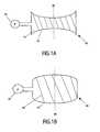
- the lens system 40comprises a resilient membrane 42 filled with a fluid 44.
- the pressure of the fluid 44 within the membraneis controlled by means of a pump 46.
- the dotted lineillustrates the optical axis 90 of the lens system 40.
- the membrane 42acts as a variable lens, with the shape (and hence power) of the lens varying in dependence upon the pressure of the fluid 44.
- Figure 1Ashows the fluid 44 at a low pressure i.e. with the membrane 42 forming a bi-concave lens.
- Figure 1Bshows the fluid 44 at a higher pressure, with the membrane 42 forming a bi-convex lens.
- Electrowetting devicesare devices that utilise the electrowetting phenomenon to operate. In electrowetting, the three-phase contact angle is changed with applied voltage. The three-phases constitute two fluids and a solid.
- FIG. 2is a cross-sectional view of such a typical optical device.
- the devicehas two immiscible fluids 80, 87 confined in a sealed space 92 (i.e. a chamber or cavity).
- the term immiscibleindicates that the two fluids do not mix.
- the first fluid 80is an insulator (e.g. silicone oil) and the second fluid 87 electro conductive (e.g. a mixture of water and ethyl alcohol).
- the first fluid 80 and the second fluid 87have different refractive indices.
- a voltage from a voltage supply 50can be applied to the two electrodes 51, 52 so as to produce an electric field between the first fluid 87 and the electrode 52 (an insulating layer 65 prevents the second electrode 52 contacting the conductive second fluid).
- the device in Figure 1has a water-repellent film 60 of diameter D1 on the insulating layer 65 surrounded by a ring of a hydrophilic agent 70 so as to locate the first fluid 80.
- the lens shapeis defined by a variable voltage, with the lens shape being affected by any nonuniformities of the insulating layer.
- the configurationrequires a relatively high voltage to alter the shape of the interface 85.
- the insulating layermay suffer from charging (especially at high voltages). If the insulating layer is charged unequally, this will lead to unequal contact angles, and thus to non-spherical lens. Further, it is not possible for such a lens to vary from being a positive power lens to a negative power lens (or vice versa).
- WO 02069016 A2discloses devices which utilize elements carried by a fluid in a microchannel to switch, attenuate, shutter, filter, or phase shift optical signals.
- the fluid in the microchannelis moved using e.g. electrocapillarity, differential-pressure electrocapillarity, electrowetting, continuous electrowetting, electrophoresis, electroosmosis, dielectrophoresis, electrohydrodynarnic electrohydrodynamic pumping, thermocapillary, thermal expansion, dielectric pumping, and/or variable dielectric pumping.
- US 5864128 Adiscloses a system and method for scanning a bar code target by continuously varying the focal range of a bar code scanning system.
- a light sourceis provided for generating light rays, and a lens is provided for focusing the light rays.
- the lenshas a variable focal length.
- the focused light raysare scanned across the bar code target with a beam scanner. While the focused light rays are being scanned, the focal length of the lens is continuously varied.
- a pliable gel state lens systemis used herein to receive a continuously variable focus.
- US 2001017985 A1dicloses an optical device capable of controlling its optical transmittance.
- the optical devicehas a first liquid conductive or having a polarity and a second liquid.
- the first and second liquidsare substantially equal in refractive index but differ in transmittance.
- the first and second liquidsdo not mix with each other.
- the first and second liquidsare sealingly contained in a container in such state that the boundary therebetween has a predetermined shape.
- JP 01302301 and DE197710668disclose further relevant prior art.
- the present inventionprovides a variable lens comprising: a chamber; an optical axis extending through the chamber; the chamber containing a first fluid and a second fluid in contact over a meniscus extending transverse the optical axis, the perimeter of the meniscus being fixedly located on an internal surface of the chamber by a change in the wettability of the internal surfcae, the fluids being substantially immiscible and having different indices of refraction; and at least one pump arranged to controllably alter the shape of the meniscus by altering the relative volume of each of said fluids contained within the chamber.
- the meniscus between the two fluidsacts as a lens, and so the effective shape of the lens can easily be adjusted by changing the shape of the meniscus. As no mechanical components are required within the optical path of the lens, then the optical path does not suffer from mechanical wear and tear. Further, the lens shape is not directly related to a change in voltage, thus making the lens independent of charging effects within the insulating layer. Further, the design allows lenses to be produced that are adjustable from being positive power lenses to negative power lenses (and vice versa), thus allowing a wide range in design freedom.
- the present inventionprovides an optical device comprising a variable lens, the lens comprising: a chamber; an optical axis extending through the chamber; the chamber containing a first fluid and a second fluid in contact over a meniscus extending transverse the optical axis, the perimeter of the meniscus being fixedly located on an internal surface of the chamber, the fluids being substantially immiscible and having different indices of refraction; and at least one pump arranged to controllably alter the shape of the meniscus by altering the relative volume of each of said fluids contained within the chamber.
- the present inventionprovides a method of manufacturing a variable lens, the method comprising: providing a chamber, with an optical axis extending through the chamber placing a first fluid and a second fluid in the chamber such that the two fluids are in contact over a meniscus extending transverse the optical axis, the perimeter of the meniscus being fixedly located on an internal surface of the chamber, the fluids being substantially immiscible and having different indices of refraction; and providing at least one pump arranged to controllably alter the shape of the meniscus by altering the relative volume of each of said fluids contained within the chamber.
- the present inventionprovides a method of manufacturing an optical device, the method comprising the steps of: providing a variable lens, the variable lens comprising: a chamber; an optical axis extending through the chamber; the chamber containing a first fluid and a second fluid in contact over a meniscus extending transverse the optical axis, the perimeter of the meniscus being fixedly located on an internal surface of the chamber, the fluids being substantially immiscible and having different indices of refraction; and at least one pump arranged to controllably alter the shape of the meniscus by altering the relative volume of each of said fluids contained within the chamber.
- FIG. 3Ashows a variable lens in accordance with a first embodiment of the present invention.
- the lens 100can be regarded as being formed of two distinct elements: a lens function formed by the meniscus 150 between two fluids 130, 140, and a pump 110 arranged to alter the shape of the lens function.
- a fluidis a substance that alters its shape in response to any force, that tends to flow or to conform to the outline of its chamber, and that includes gases, liquids, vapours, and mixtures of solids and liquids capable of flow.
- the two fluids 130, 140are substantially immiscible i.e. the two fluids do not mix.
- the two fluids 130, 140have different refractive indices.
- a lens functionis thus provided by the meniscus 150 formed along the contact area of the two fluids, as the fluids have different refractive indices.
- a lens functionis the ability of the meniscus 150 to focus (converge or diverge) one or more wavelengths of the light. In this particular embodiment, it is assumed that fluid 130 has a higher refractive index than fluid 140.
- the two fluidsare preferably of substantially equal density, so as to minimise the effects of gravity upon the lens 100.
- the fluids 130, 140are enclosed within a chamber 125.
- the chamber 125takes the form of a longitudinally extending tube, the tube having side walls defined by internal surfaces 120.
- An optical axisextends longitudinally through the tube.
- the tubeis a cylindrical tube, of constant circular cross-sectional area, and the optical axis is co-axial with the tube axis.
- Additional walls 121, 122extend across the ends of the tubes so as to form a chamber 125 enclosing the fluids. At least the portions of the walls 121, 122 of the chamber 125 lying along the optical axis 90 are transparent. If desired, one or both of these walls 121, 122 may be lens shaped.
- the meniscus 150 between the two fluids 130, 140extends transverse the optical axis 90 of the lens 100.
- transverseindicates that the meniscus crosses (i.e. it extends across) the optical axis, and it is not parallel to the optical axis; the meniscus 150 may cross the optical axis 90 at any desired angle.
- the perimeter of the meniscus 150is defined by the side walls 120 of the tube.
- Wettabilityis the extent by which an area is wetted (covered) by a fluid. For instance, if the fluid 130 is water, and the fluid 140 is an oil, then the internal surface of the wall 122 may be hydrophilic so as to attract the fluid 130, and not attract the fluid 140.
- the perimeter of the meniscus 150contacts the surfaces 120 of the side walls of the tube.
- the perimeter of the meniscusis fixedly located on the surface 120.
- the position 151 at which the perimeter of the meniscus 150 touches the surface 120is fixed i.e. the meniscus perimeter is pinned to the surface.
- the meniscus perimeteris fixed to the surface by an abrupt change in wettability of the surface at position 151 e.g., at position 151 the surface 120 changes from being hydrophobic to hydrophilic.
- the shape of the meniscus 150is determined by both the pressure difference between the two fluids and by the internal diameter of the cylinder.
- the meniscus 150 illustratedis convex (as viewed from fluid 130).
- a pump 110 connected to the fluid filled chamber 125is arranged to pump quantities of one or more of the fluids to and from the chamber 125.
- the pump 110is arranged to simultaneously increase the volume of the fluid 130 and to decrease the volume of the fluid 140 (and vice versa), so as to maintain the same total volume of the two fluids within the chamber 125.
- the resultwill be that the shape of the meniscus 150 will be changed, as the perimeter of the meniscus is pinned to the surface 120.
- the meniscus shapemay change to be more convex i.e. to form the meniscus indicated by the dotted line 150'.
- the meniscusmay change shape to that indicated by the dotted line 150" i.e. the meniscus becomes concave (as viewed from fluid 130). It will be appreciated that by altering the volumes of the fluids within the chamber 125, then the meniscus shape can be changed from being convex, to planar, to concave.
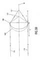
- Figure 3Billustrates the effective optical function, when the refractive index of fluid 130 is higher than fluid 140, provided by the meniscus 150 i.e. it is that of a plano convex lens 160, of focal length f.
- the meniscus 150effectively provides the function of a lens 160, which would bring parallel light 170 (incident upon the lens in a direction parallel to the optical axis 90), to a focus 172 a distance f from the lens.
- the effective lens functionalso changes, to that shown by dotted line 160'.
- the lenswill be of a higher power i.e. if will-have a shorter focal length, bringing parallel light 1702a focus 172' a shorter distance from the lens.
- the meniscus 150is fixedly located by a change in the wettability of the surface.
- other techniquesmay be used to fix the position of the meniscus perimeter.
- Figures 4A , 4B and 4Cshow cross sectional views of variable lenses 200, 220, 240 in accordance with further embodiments of the present invention. Identical reference numerals denote similar features.
- the chamber 125 of the device 200can be envisaged as being in two portions (125a, 125b). Both portions 125a, 125b are cylindrically circular tubes, each closed at one end. The two portions 125a and 125b are of different circular cross-sections, with one portion (125b) being smaller than the other. Consequently, where the two tubes are joined, a step with an external corner is produced.
- the meniscusis pinned in position by a change in geometry of the surface 120 that the meniscus contacts.
- the perimeter of the meniscuscontacts the corner (position 151) of the step in surface 120. This abrupt change in geometry is sufficient to fixedly locate the perimeter of the meniscus.
- the position at which the meniscus contactsis a surface undergoing an abrupt change in angle.
- the greater the change in anglee.g. the more acute or sharper the edge or corner, the greater the pinning action of the meniscus, thus allowing the meniscus to undergo a greater change in radius of curvature.
- figure 4Bshows a device 220 in which an annulus (or ring) extends around a portion of the internal surface 120.
- the plane of the annulusis perpendicular to the optical axis 90.
- the annulushas a triangular cross-section, such that a sharp corner is formed on the internal surface of the ring. The meniscus contacts this corner (position 151).
- Figure 4Cshows an alternative example, generally similar to that shown in Figure 4B .
- the annulusis very thin, such that the internal surface of the annulus is effectively a spike.
- the meniscus 150contacts the ring at this sharp internal surface (position 151).
- Other appropriate changes in geometrywill be apparent to the skilled person as being suitable to fix the position of the meniscus 150.
- the meniscus 150may be pinned in position by both a change in geometry and a change in wettability.
- the pinning effectmay be enhanced by abruptly varying the wettability of the chamber wall at the point where the sharp corner is located.
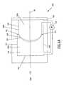
- FIG. 5shows an alternative embodiment of the present invention, in which the pumping is performed by electrowetting.
- the cylinder defining the chamber 125 containing the two fluidsis formed of a hydrophilic material e.g. glass.
- the first fluid 130 in this embodimentis water, with the second fluid 140 being an oil.
- the upper portion 122 of the internal surface 120 defining the chamber 125is coated with a hydrophobic layer. The result will be that the water will wet the glass, but not the hydrophobic coating. Consequently, this change in wettability will pin the perimeter of the meniscus 150 into position. It will be appreciated that the quality of the circumference of the lens function provided by the meniscus is determined by the accuracy by which the coating can be deposited (or removed if the coating is first applied to all of the internal surface, then selectively removed).
- the layers of materialcould be partially removed by a lathe, or by lithographic techniques. Precise changes in geometry may be obtained by a number of techniques, including injection moulding.
- a channel 116connects the two immiscible liquids (water and oil). The liquids can be pumped through this channel 116, and consequently the volume of the liquids within the chamber 125 will be changed, and hence the radius of curvature of the meniscus 150 in the chamber also changed.
- Electrowettingis utilised to change the curvature (and hence position) of this meniscus 112, with the result being that the volume of fluids within the chamber 125 will be altered. Electrowetting is performed by applying a voltage between the electrodes 114 and the electrode 118, such that the three-phase contact angle between the two fluids 130, 140 and the surface of the channel 116 changes.
- the radius of the channel 116is much smaller than the radius of the chamber 125. Consequently, a relatively small change in the contact angle of the meniscus 112 in the channel 116 will lead to a much larger change in contact angle of the meniscus 150 in the chamber 125.
- the channel 116must be long enough to accommodate the desired range and movement of the meniscus 112.
- the channel 116could be formed of a tube e.g. a flexible tube, or by a second cylinder (e.g. a larger cylinder could be placed around the first cylinder, similar to the arrangement shown in Figure 4 ).
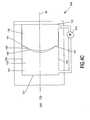
- Figure 6shows a variable lens 300 in accordance with another embodiment of the present invention.
- the two fluids 130, 140 defining the meniscus 150 of the lensare immiscible, but are not necessarily suitable for electrowetting.
- the first fluid 130could be a fluorinated oil, with the second fluid 140 being a hydrocarbon oil.
- the fluorinated oilhas a very low refractive index, which makes it possible to obtain a large difference in refractive index between the two fluids.
- the perimeter of the meniscus 150is again pinned in position by an abrupt change in wettability.
- the upper portion of the internal surface of the chamber 125is coated by a layer that is wettable by hydrocarbon oil (e.g. polyethylene), with the remainder of the internal surface coated by a layer wettable by fluorinated oil(e.g. Teflon).
- a volume of water 135(termed a "water slug") lies within the channel 116. Assuming the hydrocarbon oil 140 is suitable for electrowetting, then the water slug in the channel can be moved with electrowetting, this being reflected by a corresponding movement of the fluids 130 and 140 out of the channel. Consequently, by the pump action provided by the water slug 135, the shape of the large meniscus 150 may be changed, thus changing the power of the lens.
- Such a lens 300is an example how it is not necessary for the two liquids providing the meniscus 150 for the lens action to be suitable for electrowetting, the two liquids merely have to be immiscible.
- one of the fluids 130, 140is suitable for electrowetting, with an additional fluid (slug 135) provided to allow the electrowetting effect to be used as a pump.
- the fluidsare moved by another pump action e.g. a mechanical pump, the range in possible liquids becomes even larger. Appropriate design thus allows a wide choice in the type of fluids selected.
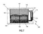
- FIG. 7shows a lens 350 in accordance with yet a further embodiment of the present invention.
- the lens 350is generally similar to the lens 250 shown in Figure 5 .
- a central pillar 124has been introduced into the chamber 125.
- the pillar 124is coated with a hydrophobic layer 122 at the same height (i.e. relative position perpendicular to the optical axis 90) as the outer cylinder wall 122.
- the resultis that the pinned meniscus 150 is donut shaped.
- the meniscusnow introduces no optical power, but does introduce a spherical aberration.
- the extent of the spherical aberration introduced by the meniscus 150will depend on the curvature of the donut shaped meniscus, with a wide range of spherical aberration being potentially possible. Consequently, such a lens can be used as an aberration corrector.
- the pillar 124takes the form of a circular cylinder, coaxial with the optical axis 90.
- the pillarcould in fact take any desired shape, or any desired positon within the chamber 125.
- the change in wettability on the pillar 124need not be at the same height as the wettability change on surface 120.
- Various types of pumpmay be used as the pump 110.
- international patent application WO 02/069016describes a number of ways of how fluid can be moved e.g. electro-capillary differential-pressure electro-capillarity, electrowetting, continuous electrowetting, electrophoresis, electroosmosis, dielectrophoresis, electrohydrodynamic pumping, thermocapillary, thermal expansion, dielectric pumping, or variable dielectric pumping, any of which could be used to provide the pump action required by the pump 110.
- the pumpcould be a mechanical pump.
- the tubeis described as a circular tube (i.e. it has a circular cross-section), it will be appreciated that in fact the tube can have any desired cross-section e.g. square, rectangular or elliptical.
- the lenshas been described as being formed of two bodies of fluid, with an interface between the fluid providing the lens function.
- the lenscould in fact comprise any number of bodies of fluids.
- the lenscould comprise two volumes of oil separated by a volume of water. Consequently, a double lens with two menisci would be produced, each meniscuscorresponding to an interface between the water and a respective volume of oil. Each of the two menisci could be pinned.
- variable lenses of the present inventioncan form part of any optical device requiring a lens.
- Figure 8shows a device 1 for scanning an optical record carrier 2, including an objective lens system 18 comprising a variable focus lens in accordance with an embodiment of the present invention.
- the record carriercomprises a transparent layer 3, on one side of which an information layer 4 is arranged.
- the side of the information layer facing away from the transparent layeris protected from environmental influences by a protection layer 5.
- the side of the transparent layer facing the deviceis called the entrance face 6.
- the transparent layer 3acts as a substrate for the record carrier by providing mechanical support for the information layer.
- the transparent layermay have the sole function of protecting the information layer, while the mechanical support is provided by a layer on the other side of the information layer, for instance by the protection layer 5 or by a further information layer and a transparent layer connected to the information layer 4.
- Informationmay be stored in the information layer 4 of the record carrier in the form of optically detectable marks arranged in substantially parallel, concentric or spiral tracks, not indicated in the Figure.
- the marksmay be in any optically readable form, e.g. in the form of pits, or areas with a reflection coefficient or a direction of magnetisation different from their surroundings, or a combination of these forms.
- the scanning device 1comprises a radiation source 11 that can emit a radiation beam 12.
- the radiation sourcemay be a semiconductor laser.
- a beam splitter 13reflects the diverging radiation beam 12 towards a collimator lens 14, which converts the diverging beam 12 into a collimated beam 15.
- the collimated beam 15is incident on an objective system 18.
- the objective systemmay comprise one or more lenses and/or a grating.
- the objective system 18has an optical axis 19.
- the objective system 18changes the beam 17 to a converging beam 20, incident on the entrance face 6 of the record carrier 2.
- the objective systemhas a spherical aberration correction adapted for passage of the radiation beam through the thickness of the transparent layer 3.
- the converging beam 20forms a spot 21 on the information layer 4.
- Radiation reflected by the information layer 4forms a diverging beam 22, transformed into a substantially collimated beam 23 by the objective system 18 and subsequently into a converging beam 24 by the collimator lens 14.
- the beam splitter 13separates the forward and reflected beams by transmitting at least part of the converging beam 24 towards a detection system 25.
- the detection systemcaptures the radiation and converts it into electrical output signals 26.
- a signal processor 27converts these output signals to various other signals.
- One of the signalsis an information signal 28, the value of which represents information read from the information layer 4.
- the information signalis processed by an information processing unit for error correction 29.
- Other signals from the signal processor 27are the focus error signal and radial error signal 30.
- the focus error signalrepresents the axial difference in height between the spot 21 and the information layer 4.
- the radial error signalrepresents the distance in the plane of the information layer 4 between the spot 21 and the centre of a track in the information layer to be followed by the spot.
- the focus error signal and the radial error signalare fed into a servo circuit 31, which converts these signals to servo control signals 32 for controlling a focus actuator and a radial actuator respectively.
- the actuatorsare not shown in the Figure.
- the focus actuatorcontrols the position of the objective system 18 in the focus direction 33, thereby controlling the actual position of the spot 21 such that it coincides substantially with the plane of the information layer 4.
- the radial actuatorcontrols the position of the objective lens 18 in a radial direction34, thereby controlling the radial position of the spot 21 such that it coincides substantially with the central line of track to be followed in the information layer 4.
- the tracks in the Figurerun in a direction perpendicular to the plane of the Figure.
- the device of Figure 8 in this particular embodimentis adapted to scan also a second type of record carrier having a thicker transparent layer than the record carrier 2.
- the devicemay use the radiation beam 12 or a radiation beam having a different wavelength for scanning the record carrier of the second type.
- the NA of this radiation beammay be adapted to the type of record carrier.
- the spherical aberration compensation of the objective systemmust be adapted accordingly.
- the two information layersare at depths of 0.1mm and 0.08mm; they are thus separated by typically 0.02mm.
- BDBlu-ray Disc
- the two information layersare at depths of 0.1mm and 0.08mm; they are thus separated by typically 0.02mm.
- some 200m ⁇ of unwanted spherical aberrationarises, which needs to be compensated. This can be achieved by introducing spherical aberration into the objective system 18, such that the spherical aberrations cancel out.
- spherical aberrationis introduced into the objective system 18 by altering the collimation of the beam 15 incident upon the objective system 18, by using a variable lens in accordance with the present invention.
- a variable lenscan be incorporated as an extra device within the optical path of the beam 15 or the variable lens can form part of the lens 14 (e.g. lens 14 is a compound lens).
- lens 14is a compound lens.
- Figure 9illustrates a variable focus image capture device 400 including a lens in accordance with an alternative embodiment of the present invention.
- the device 400includes a compound variable focus lens including a cylindrical tube of surfaces 120, a ridged front lens 404, and ridged rear lens 406.
- the spacing enclosed by the two lenses and the tubeforms a cylindrical fluid chamber 125.
- the fluid chamber 125holds the first and second fluids 130 and 140.
- the two fluidstouch along a meniscus 150.
- the meniscusforms a meniscus lens of variable shape, as previously described, depending upon the respective volume of each fluid provided to the chamber by the pump 422.
- the front lens 404is a convex-convex lens of highly refracting plastic, such as polycarbonate or cyclic olefin copolymer (COC), and having a positive power. At least one of the surfaces of the front lens is aspherical, to provide the desired initial focusing characteristics.
- the rear lens element 406is formed of a low dispersive plastic, such as COC, and includes an aspherical lens surface which acts as a field flattener. The other surface of the rear lens element may be flat, spherical or aspherical.
- a glare stop 416 and an aperture stop 418are added to the front of the lens.
- a pixellated image sensor 420such as a CMOS (Complementary Metal Oxide Silicon) sensor array, is located in a sensor plane behind the lens.
- CMOSComplementary Metal Oxide Silicon
- the pump 422drives the lens, in accordance with a focus control signal, derived by focus control processing of the image signals, so as to provide an object range of between infinity and 10cm.
- the front lens element 404is preferably formed as a single body with the tube, the tube being closed off by the rear lens 406 to form a sealed unit.
- the second lens element 406may be extended, in relation to that shown in figure 8 , and the flat rear surface of the lens element 406 may be replaced by an angled mirror surface, preferably angled at 45°, to allow the image sensor 420 to be placed below the lens, in order to reduce the dimensions of the lens.
- the inner surfaces of the front lens 404 and the rear lens 406may be coated with a protective layer to avoid incompatibility of the material from which the lens are made with the fluids 130 and 140.
- the protective layermay also have anti-reflection characteristics.
- variable lensin which the shape of the lens can easily be adjusted by controllably altering the shape of the meniscus between the two fluids. As no mechanical components are required within the optical path, then the optical path does not suffer from mechanical wear and tear. Further, the lens may be adjusted between having a positive power and a negative power.
Landscapes
- Physics & Mathematics (AREA)
- Optics & Photonics (AREA)
- General Physics & Mathematics (AREA)
- Mechanical Light Control Or Optical Switches (AREA)
- Lenses (AREA)
Abstract
Description
- The present invention relates to a variable lens, to optical devices including such a lens, and to methods of manufacturing such lenses and such devices.
- A lens is a device that can focus (converge or diverge) one or more wavelengths of light. The term light is understood to include both visible electromagnetic radiation, and other wavelengths of electromagnetic radiation.
- A variable (or adjustable) lens is a lens in which one or more properties of the lens can be controllably adjusted e.g. in which either the focal length or the position of the lens can be altered.
DE 19710668 describes avariable lens system 40, as illustrated inFigures 1A and 1B . Thelens system 40 comprises aresilient membrane 42 filled with afluid 44. The pressure of thefluid 44 within the membrane is controlled by means of apump 46. The dotted line illustrates theoptical axis 90 of thelens system 40. Themembrane 42 acts as a variable lens, with the shape (and hence power) of the lens varying in dependence upon the pressure of thefluid 44.Figure 1A shows thefluid 44 at a low pressure i.e. with themembrane 42 forming a bi-concave lens.Figure 1B shows thefluid 44 at a higher pressure, with themembrane 42 forming a bi-convex lens.- Such a system posses a number of disadvantages. Due to the movement of the membrane surface, it is difficult to maintain good optical properties and it is susceptible to vibrations. Further, it is susceptible to mechanical fatigue. Control of the shape of the lens is not only dependent upon both gravity and the pressure of the
fluid 44, but also the resilience of themembrane 42. Consequently, obtaining a range of desired lens shapes can be problematic, particularly if the elasticity of themembrane 42 changes over time. Additionally, flexible membranes are not normally gas tight, resulting in the evaporation of the fluid from the device over time. - Variable focus lenses based on electrowetting devices are also known. Electrowetting devices are devices that utilise the electrowetting phenomenon to operate. In electrowetting, the three-phase contact angle is changed with applied voltage. The three-phases constitute two fluids and a solid.
- International patent application
WO 99/18456 US 6369954 B1 ) describes a variable focus lens utilising the electrowetting effect.Figure 2 is a cross-sectional view of such a typical optical device. The device has twoimmiscible fluids first fluid 80 is an insulator (e.g. silicone oil) and thesecond fluid 87 electro conductive (e.g. a mixture of water and ethyl alcohol). Thefirst fluid 80 and thesecond fluid 87 have different refractive indices. - A voltage from a
voltage supply 50 can be applied to the twoelectrodes first fluid 87 and the electrode 52 (aninsulating layer 65 prevents thesecond electrode 52 contacting the conductive second fluid). - By varying the voltage applied to the
second fluid 87, the shape of aninterface 85 between thefirst fluid 80 and thesecond fluid 87 is altered, so as to change the lens function provided by theinterface 85. The device inFigure 1 has a water-repellent film 60 of diameter D1 on the insulatinglayer 65 surrounded by a ring of ahydrophilic agent 70 so as to locate thefirst fluid 80. - This electrowetting lens also posses a number of disadvantages. For instance, the lens shape is defined by a variable voltage, with the lens shape being affected by any nonuniformities of the insulating layer. The configuration requires a relatively high voltage to alter the shape of the
interface 85. Further, the insulating layer may suffer from charging (especially at high voltages). If the insulating layer is charged unequally, this will lead to unequal contact angles, and thus to non-spherical lens. Further, it is not possible for such a lens to vary from being a positive power lens to a negative power lens (or vice versa). WO 02069016 A2 US 5864128 A discloses a system and method for scanning a bar code target by continuously varying the focal range of a bar code scanning system. A light source is provided for generating light rays, and a lens is provided for focusing the light rays. The lens has a variable focal length. The focused light rays are scanned across the bar code target with a beam scanner. While the focused light rays are being scanned, the focal length of the lens is continuously varied. A pliable gel state lens system is used herein to receive a continuously variable focus.US 2001017985 A1 dicloses an optical device capable of controlling its optical transmittance. The optical device has a first liquid conductive or having a polarity and a second liquid. The first and second liquids are substantially equal in refractive index but differ in transmittance. The first and second liquids do not mix with each other. The first and second liquids are sealingly contained in a container in such state that the boundary therebetween has a predetermined shape. When a voltage is applied between these liquids through electrodes formed in such a place or condition as to avoid interference with passage of a bundle of rays incident upon the optical element, the output of the applied voltage is selected under control to change the shape of the boundary, thereby changing the quantity of transmitted light in the bundle of rays traveling through the optical device.JP 01302301 DE197710668 disclose further relevant prior art.- Berge, B. et al.: "Variable focal lens controlled by an external voltage: An application of electrowetting", in The European Physical Journal E, vol.3, no.2, 10/2002 discloses a lens of variable focal length that uses electrocapillarity in order to change the contact angle of a transparent drop. The key point of this is the application of gradients of wettability, which control the shape of the drop edge.
- It is an aim of embodiments of the present invention to provide a variable lens that addresses one or more problems of the prior art, whether referred to herein or otherwise. It is also an aim of the present invention to provide optical devices incorporating such lenses, and methods of manufacturing such lens and such devices.
- In a first aspect, the present invention provides a variable lens comprising: a chamber; an optical axis extending through the chamber; the chamber containing a first fluid and a second fluid in contact over a meniscus extending transverse the optical axis, the perimeter of the meniscus being fixedly located on an internal surface of the chamber by a change in the wettability of the internal surfcae, the fluids being substantially immiscible and having different indices of refraction; and at least one pump arranged to controllably alter the shape of the meniscus by altering the relative volume of each of said fluids contained within the chamber.
- The meniscus between the two fluids acts as a lens, and so the effective shape of the lens can easily be adjusted by changing the shape of the meniscus. As no mechanical components are required within the optical path of the lens, then the optical path does not suffer from mechanical wear and tear. Further, the lens shape is not directly related to a change in voltage, thus making the lens independent of charging effects within the insulating layer. Further, the design allows lenses to be produced that are adjustable from being positive power lenses to negative power lenses (and vice versa), thus allowing a wide range in design freedom.
- In another aspect, the present invention provides an optical device comprising a variable lens, the lens comprising: a chamber; an optical axis extending through the chamber; the chamber containing a first fluid and a second fluid in contact over a meniscus extending transverse the optical axis, the perimeter of the meniscus being fixedly located on an internal surface of the chamber, the fluids being substantially immiscible and having different indices of refraction; and at least one pump arranged to controllably alter the shape of the meniscus by altering the relative volume of each of said fluids contained within the chamber.
- In a further aspect, the present invention provides a method of manufacturing a variable lens, the method comprising: providing a chamber, with an optical axis extending through the chamber placing a first fluid and a second fluid in the chamber such that the two fluids are in contact over a meniscus extending transverse the optical axis, the perimeter of the meniscus being fixedly located on an internal surface of the chamber, the fluids being substantially immiscible and having different indices of refraction; and providing at least one pump arranged to controllably alter the shape of the meniscus by altering the relative volume of each of said fluids contained within the chamber.
- In another aspect, the present invention provides a method of manufacturing an optical device, the method comprising the steps of: providing a variable lens, the variable lens comprising: a chamber; an optical axis extending through the chamber; the chamber containing a first fluid and a second fluid in contact over a meniscus extending transverse the optical axis, the perimeter of the meniscus being fixedly located on an internal surface of the chamber, the fluids being substantially immiscible and having different indices of refraction; and at least one pump arranged to controllably alter the shape of the meniscus by altering the relative volume of each of said fluids contained within the chamber.
- Other aims and advantages of the present invention will be apparent from the preferred features as set out in the accompanying claims.
- For a better understanding of the invention, and to show how embodiments of the same may be carried into effect, reference will now be made, by way of example, to the accompanying diagrammatic drawings in which:
Figures 1A and 1B show a known variable lens in schematic cross-section in two different configurations;Figure 2 illustrates a schematic cross-section of a known type of electrowetting variable lens;Figures 3A and3B illustrate respectively a schematic cross-section of a variable lens and the equivalent optical function provided by the variable lens in accordance with a first embodiment of the present invention;Figures 4A-4C illustrates schematic cross-sections of variable lenses in accordance with further embodiments of the present invention;Figure 5 illustrates a schematic cross-section of a variable lens in accordance with a further embodiment of the present invention;Figure 6 illustrates a schematic cross-section of a variable lens in accordance with another embodiment of the present invention;Figure 7 illustrates a schematic cross-section of a variable lens in accordance with a further embodiment of the present invention;Figure 8 illustrates a device for scanning an optical record carrier including a variable lens in accordance with an embodiment of the present invention; andFigure 9 illustrates a variable focus image capture device including a variable lens in accordance with an embodiment of the present invention.Figure 3A shows a variable lens in accordance with a first embodiment of the present invention. Thelens 100 can be regarded as being formed of two distinct elements: a lens function formed by themeniscus 150 between twofluids pump 110 arranged to alter the shape of the lens function.- A fluid is a substance that alters its shape in response to any force, that tends to flow or to conform to the outline of its chamber, and that includes gases, liquids, vapours, and mixtures of solids and liquids capable of flow.
- The two
fluids fluids meniscus 150 formed along the contact area of the two fluids, as the fluids have different refractive indices. A lens function is the ability of themeniscus 150 to focus (converge or diverge) one or more wavelengths of the light. In this particular embodiment, it is assumed thatfluid 130 has a higher refractive index thanfluid 140. - The two fluids are preferably of substantially equal density, so as to minimise the effects of gravity upon the
lens 100. - The
fluids chamber 125. In this embodiment thechamber 125 takes the form of a longitudinally extending tube, the tube having side walls defined byinternal surfaces 120. An optical axis extends longitudinally through the tube. In this particular example, the tube is a cylindrical tube, of constant circular cross-sectional area, and the optical axis is co-axial with the tube axis.Additional walls chamber 125 enclosing the fluids. At least the portions of thewalls chamber 125 lying along theoptical axis 90 are transparent. If desired, one or both of thesewalls - The
meniscus 150 between the twofluids optical axis 90 of thelens 100. The term transverse indicates that the meniscus crosses (i.e. it extends across) the optical axis, and it is not parallel to the optical axis; themeniscus 150 may cross theoptical axis 90 at any desired angle. The perimeter of themeniscus 150 is defined by theside walls 120 of the tube. - Typically, in order to locate the
fluids chamber 125, different areas of the chamber will have different wettabilities for each fluid, such that each fluid will be attracted by a respective area. Wettability is the extent by which an area is wetted (covered) by a fluid. For instance, if the fluid 130 is water, and the fluid 140 is an oil, then the internal surface of thewall 122 may be hydrophilic so as to attract the fluid 130, and not attract thefluid 140. - The perimeter of the
meniscus 150 contacts thesurfaces 120 of the side walls of the tube. The perimeter of the meniscus is fixedly located on thesurface 120. In other words, theposition 151 at which the perimeter of themeniscus 150 touches thesurface 120 is fixed i.e. the meniscus perimeter is pinned to the surface. In this particular embodiment, the meniscus perimeter is fixed to the surface by an abrupt change in wettability of the surface atposition 151 e.g., atposition 151 thesurface 120 changes from being hydrophobic to hydrophilic. - The shape of the
meniscus 150 is determined by both the pressure difference between the two fluids and by the internal diameter of the cylinder. Themeniscus 150 illustrated is convex (as viewed from fluid 130). - A
pump 110 connected to the fluid filledchamber 125 is arranged to pump quantities of one or more of the fluids to and from thechamber 125. - In this particular example, the
pump 110 is arranged to simultaneously increase the volume of the fluid 130 and to decrease the volume of the fluid 140 (and vice versa), so as to maintain the same total volume of the two fluids within thechamber 125. The result will be that the shape of themeniscus 150 will be changed, as the perimeter of the meniscus is pinned to thesurface 120. - For instance, if
extra fluid 130 is added to thechamber 125, then the meniscus shape may change to be more convex i.e. to form the meniscus indicated by the dotted line 150'. Alternatively, ifextra fluid 140 is added, then the meniscus may change shape to that indicated by the dottedline 150" i.e. the meniscus becomes concave (as viewed from fluid 130). It will be appreciated that by altering the volumes of the fluids within thechamber 125, then the meniscus shape can be changed from being convex, to planar, to concave. - It is expected that the maximum curvature of the meniscus shape would be when the meniscus forms a half-sphere. However, it will be appreciated that there is likely to be a threshold pressure at which the meniscus moves, when the pressure becomes so great that the pinning action of the meniscus is overcome, with the result that the meniscus will subsequently move position. Such a threshold pressure is dependent on the magnitude of the change in wettability.
Figure 3B illustrates the effective optical function, when the refractive index offluid 130 is higher thanfluid 140, provided by themeniscus 150 i.e. it is that of a planoconvex lens 160, of focal length f. In other words, themeniscus 150 effectively provides the function of alens 160, which would bring parallel light 170 (incident upon the lens in a direction parallel to the optical axis 90), to a focus 172 a distance f from the lens.- When the meniscus has changed shape (i.e. to the shape shown by the dotted line 150' in
Figure 3A ), then the effective lens function also changes, to that shown by dotted line 160'. As the meniscus 150' is more curved thanmeniscus 150, then the lens will be of a higher power i.e. if will-have a shorter focal length, bringing parallel light 1702a focus 172' a shorter distance from the lens. - In the embodiment shown in
Figure 3A , themeniscus 150 is fixedly located by a change in the wettability of the surface. However, it will be appreciated that other techniques may be used to fix the position of the meniscus perimeter. - For instance,
Figures 4A ,4B and4C show cross sectional views ofvariable lenses - The
chamber 125 of thedevice 200 can be envisaged as being in two portions (125a, 125b). Bothportions portions - In this particular example, the meniscus is pinned in position by a change in geometry of the
surface 120 that the meniscus contacts. In particular, the perimeter of the meniscus contacts the corner (position 151) of the step insurface 120. This abrupt change in geometry is sufficient to fixedly locate the perimeter of the meniscus. - It will be appreciated that other changes in geometry may be used to fixedly locate the
meniscus 150. Preferably, the position at which the meniscus contacts is a surface undergoing an abrupt change in angle. The greater the change in angle (e.g. the more acute or sharper the edge or corner), the greater the pinning action of the meniscus, thus allowing the meniscus to undergo a greater change in radius of curvature. - By way of example,
figure 4B shows adevice 220 in which an annulus (or ring) extends around a portion of theinternal surface 120. Preferably, the plane of the annulus is perpendicular to theoptical axis 90. The annulus has a triangular cross-section, such that a sharp corner is formed on the internal surface of the ring. The meniscus contacts this corner (position 151). Figure 4C shows an alternative example, generally similar to that shown inFigure 4B . In this particular instance, the annulus is very thin, such that the internal surface of the annulus is effectively a spike. Themeniscus 150 contacts the ring at this sharp internal surface (position 151). Other appropriate changes in geometry will be apparent to the skilled person as being suitable to fix the position of themeniscus 150.- If desired, the
meniscus 150 may be pinned in position by both a change in geometry and a change in wettability. For instance, infigures 4A ,4B and4C the pinning effect may be enhanced by abruptly varying the wettability of the chamber wall at the point where the sharp corner is located. - It will be appreciated that pumping of fluids into and out of the
chamber 125 can be done in many ways, for instance by a mechanical pump.Figure 5 shows an alternative embodiment of the present invention, in which the pumping is performed by electrowetting. - In the
device 250 shown inFigure 5 , it is assumed that the cylinder defining thechamber 125 containing the two fluids is formed of a hydrophilic material e.g. glass. Thefirst fluid 130 in this embodiment, is water, with thesecond fluid 140 being an oil. Theupper portion 122 of theinternal surface 120 defining thechamber 125 is coated with a hydrophobic layer. The result will be that the water will wet the glass, but not the hydrophobic coating. Consequently, this change in wettability will pin the perimeter of themeniscus 150 into position. It will be appreciated that the quality of the circumference of the lens function provided by the meniscus is determined by the accuracy by which the coating can be deposited (or removed if the coating is first applied to all of the internal surface, then selectively removed). - For instance, the layers of material could be partially removed by a lathe, or by lithographic techniques. Precise changes in geometry may be obtained by a number of techniques, including injection moulding.
- A
channel 116 connects the two immiscible liquids (water and oil). The liquids can be pumped through thischannel 116, and consequently the volume of the liquids within thechamber 125 will be changed, and hence the radius of curvature of themeniscus 150 in the chamber also changed. - Within the channel 116 a
further meniscus 112 exists, defining the interface between the two liquids. Electrowetting is utilised to change the curvature (and hence position) of thismeniscus 112, with the result being that the volume of fluids within thechamber 125 will be altered. Electrowetting is performed by applying a voltage between theelectrodes 114 and theelectrode 118, such that the three-phase contact angle between the twofluids channel 116 changes. - In this particular embodiment, the radius of the
channel 116 is much smaller than the radius of thechamber 125. Consequently, a relatively small change in the contact angle of themeniscus 112 in thechannel 116 will lead to a much larger change in contact angle of themeniscus 150 in thechamber 125. Thechannel 116 must be long enough to accommodate the desired range and movement of themeniscus 112. If desired, thechannel 116 could be formed of a tube e.g. a flexible tube, or by a second cylinder (e.g. a larger cylinder could be placed around the first cylinder, similar to the arrangement shown inFigure 4 ). Figure 6 shows avariable lens 300 in accordance with another embodiment of the present invention. In this particular embodiment, the twofluids meniscus 150 of the lens are immiscible, but are not necessarily suitable for electrowetting. For instance, thefirst fluid 130 could be a fluorinated oil, with thesecond fluid 140 being a hydrocarbon oil. The fluorinated oil has a very low refractive index, which makes it possible to obtain a large difference in refractive index between the two fluids.- The perimeter of the
meniscus 150 is again pinned in position by an abrupt change in wettability. The upper portion of the internal surface of thechamber 125 is coated by a layer that is wettable by hydrocarbon oil (e.g. polyethylene), with the remainder of the internal surface coated by a layer wettable by fluorinated oil(e.g. Teflon). A volume of water 135 (termed a "water slug") lies within thechannel 116. Assuming thehydrocarbon oil 140 is suitable for electrowetting, then the water slug in the channel can be moved with electrowetting, this being reflected by a corresponding movement of thefluids water slug 135, the shape of thelarge meniscus 150 may be changed, thus changing the power of the lens. - Such a
lens 300 is an example how it is not necessary for the two liquids providing themeniscus 150 for the lens action to be suitable for electrowetting, the two liquids merely have to be immiscible. In this example only one of thefluids Figure 7 shows alens 350 in accordance with yet a further embodiment of the present invention. Thelens 350 is generally similar to thelens 250 shown inFigure 5 . However, in this particular embodiment, acentral pillar 124 has been introduced into thechamber 125. Thepillar 124 is coated with ahydrophobic layer 122 at the same height (i.e. relative position perpendicular to the optical axis 90) as theouter cylinder wall 122. The result is that the pinnedmeniscus 150 is donut shaped. The meniscus now introduces no optical power, but does introduce a spherical aberration. The extent of the spherical aberration introduced by themeniscus 150 will depend on the curvature of the donut shaped meniscus, with a wide range of spherical aberration being potentially possible. Consequently, such a lens can be used as an aberration corrector.- In this
particular lens 350, thepillar 124 takes the form of a circular cylinder, coaxial with theoptical axis 90. However, it will be appreciated that the pillar could in fact take any desired shape, or any desired positon within thechamber 125. The change in wettability on thepillar 124 need not be at the same height as the wettability change onsurface 120. - Various types of pump may be used as the
pump 110. For instance, international patent applicationWO 02/069016 pump 110. Alternatively, the pump could be a mechanical pump. - Although in the above embodiments, the tube is described as a circular tube (i.e. it has a circular cross-section), it will be appreciated that in fact the tube can have any desired cross-section e.g. square, rectangular or elliptical.
- Equally, in the above embodiments, the lens has been described as being formed of two bodies of fluid, with an interface between the fluid providing the lens function. However, it will be appreciated that the lens could in fact comprise any number of bodies of fluids. For instance, the lens could comprise two volumes of oil separated by a volume of water. Consequently, a double lens with two menisci would be produced, each meniscuscorresponding to an interface between the water and a respective volume of oil. Each of the two menisci could be pinned. By altering the respective volumes of each of the bodies of fluid (i.e. by altering the volume of water contained within the tube, as well as the volume of each of the bodies of oil within the tube), both of the lens functions provided by the two menisci can be controllably altered.
- It will be appreciated that the variable lenses of the present invention can form part of any optical device requiring a lens.
Figure 8 shows adevice 1 for scanning an optical record carrier 2, including anobjective lens system 18 comprising a variable focus lens in accordance with an embodiment of the present invention. The record carrier comprises atransparent layer 3, on one side of which aninformation layer 4 is arranged. The side of the information layer facing away from the transparent layer is protected from environmental influences by aprotection layer 5. The side of the transparent layer facing the device is called theentrance face 6. Thetransparent layer 3 acts as a substrate for the record carrier by providing mechanical support for the information layer.- Alternatively, the transparent layer may have the sole function of protecting the information layer, while the mechanical support is provided by a layer on the other side of the information layer, for instance by the
protection layer 5 or by a further information layer and a transparent layer connected to theinformation layer 4. - Information may be stored in the
information layer 4 of the record carrier in the form of optically detectable marks arranged in substantially parallel, concentric or spiral tracks, not indicated in the Figure. The marks may be in any optically readable form, e.g. in the form of pits, or areas with a reflection coefficient or a direction of magnetisation different from their surroundings, or a combination of these forms. - The
scanning device 1 comprises aradiation source 11 that can emit aradiation beam 12. The radiation source may be a semiconductor laser. Abeam splitter 13 reflects the divergingradiation beam 12 towards acollimator lens 14, which converts the divergingbeam 12 into a collimatedbeam 15. The collimatedbeam 15 is incident on anobjective system 18. - The objective system may comprise one or more lenses and/or a grating. The
objective system 18 has anoptical axis 19. Theobjective system 18 changes the beam 17 to a convergingbeam 20, incident on theentrance face 6 of the record carrier 2. The objective system has a spherical aberration correction adapted for passage of the radiation beam through the thickness of thetransparent layer 3. The convergingbeam 20 forms aspot 21 on theinformation layer 4. Radiation reflected by theinformation layer 4 forms a divergingbeam 22, transformed into a substantially collimatedbeam 23 by theobjective system 18 and subsequently into a convergingbeam 24 by thecollimator lens 14. Thebeam splitter 13 separates the forward and reflected beams by transmitting at least part of the convergingbeam 24 towards adetection system 25. The detection system captures the radiation and converts it into electrical output signals 26. Asignal processor 27 converts these output signals to various other signals. - One of the signals is an
information signal 28, the value of which represents information read from theinformation layer 4. The information signal is processed by an information processing unit forerror correction 29. Other signals from thesignal processor 27 are the focus error signal andradial error signal 30. The focus error signal represents the axial difference in height between thespot 21 and theinformation layer 4. The radial error signal represents the distance in the plane of theinformation layer 4 between thespot 21 and the centre of a track in the information layer to be followed by the spot. The focus error signal and the radial error signal are fed into aservo circuit 31, which converts these signals to servo control signals 32 for controlling a focus actuator and a radial actuator respectively. The actuators are not shown in the Figure. The focus actuator controls the position of theobjective system 18 in thefocus direction 33, thereby controlling the actual position of thespot 21 such that it coincides substantially with the plane of theinformation layer 4. The radial actuator controls the position of theobjective lens 18 in a radial direction34, thereby controlling the radial position of thespot 21 such that it coincides substantially with the central line of track to be followed in theinformation layer 4. The tracks in the Figure run in a direction perpendicular to the plane of the Figure. - The device of
Figure 8 in this particular embodiment is adapted to scan also a second type of record carrier having a thicker transparent layer than the record carrier 2. The device may use theradiation beam 12 or a radiation beam having a different wavelength for scanning the record carrier of the second type. The NA of this radiation beam may be adapted to the type of record carrier. The spherical aberration compensation of the objective system must be adapted accordingly. - For instance, in dual layer BD (Blu-ray Disc) discs, the two information layers are at depths of 0.1mm and 0.08mm; they are thus separated by typically 0.02mm. When refocusing from one layer to another, due to the difference in information layer depth, some 200mλ of unwanted spherical aberration arises, which needs to be compensated. This can be achieved by introducing spherical aberration into the
objective system 18, such that the spherical aberrations cancel out. - In one embodiment of this invention, spherical aberration is introduced into the
objective system 18 by altering the collimation of thebeam 15 incident upon theobjective system 18, by using a variable lens in accordance with the present invention. Such a variable lens can be incorporated as an extra device within the optical path of thebeam 15 or the variable lens can form part of the lens 14 (e.g. lens 14 is a compound lens). By varying the shape of the meniscus within the variable lens, thebeam 15 can be varied from being parallel, to be slightly converging or diverging as required, so as to introduce the desired spherical aberration. Figure 9 illustrates a variable focusimage capture device 400 including a lens in accordance with an alternative embodiment of the present invention.- The
device 400 includes a compound variable focus lens including a cylindrical tube ofsurfaces 120, a ridgedfront lens 404, and ridgedrear lens 406. The spacing enclosed by the two lenses and the tube forms acylindrical fluid chamber 125. Thefluid chamber 125 holds the first andsecond fluids meniscus 150. The meniscus forms a meniscus lens of variable shape, as previously described, depending upon the respective volume of each fluid provided to the chamber by thepump 422. - The
front lens 404 is a convex-convex lens of highly refracting plastic, such as polycarbonate or cyclic olefin copolymer (COC), and having a positive power. At least one of the surfaces of the front lens is aspherical, to provide the desired initial focusing characteristics. Therear lens element 406 is formed of a low dispersive plastic, such as COC, and includes an aspherical lens surface which acts as a field flattener. The other surface of the rear lens element may be flat, spherical or aspherical. - A
glare stop 416 and anaperture stop 418 are added to the front of the lens. Apixellated image sensor 420, such as a CMOS (Complementary Metal Oxide Silicon) sensor array, is located in a sensor plane behind the lens. - The
pump 422 drives the lens, in accordance with a focus control signal, derived by focus control processing of the image signals, so as to provide an object range of between infinity and 10cm. - The
front lens element 404 is preferably formed as a single body with the tube, the tube being closed off by therear lens 406 to form a sealed unit. Thesecond lens element 406 may be extended, in relation to that shown infigure 8 , and the flat rear surface of thelens element 406 may be replaced by an angled mirror surface, preferably angled at 45°, to allow theimage sensor 420 to be placed below the lens, in order to reduce the dimensions of the lens. - The inner surfaces of the
front lens 404 and therear lens 406 may be coated with a protective layer to avoid incompatibility of the material from which the lens are made with thefluids - From the above examples, it will be appreciated that in embodiments of the present invention, a variable lens is provided in which the shape of the lens can easily be adjusted by controllably altering the shape of the meniscus between the two fluids. As no mechanical components are required within the optical path, then the optical path does not suffer from mechanical wear and tear. Further, the lens may be adjusted between having a positive power and a negative power.
Claims (9)
- A variable lens (100; 200; 220; 240; 250; 300; 350) comprising:- a chamber (125);- an optical axis (90) extending through the chamber (125);- the chamber containing a first fluid (130) and a second fluid (140) in contact over a meniscus (150) extending transverse the optical axis (90), the fluids (130, 140) being substantially immiscible and having different indices of refraction;
wherein the perimeter of the meniscus (150) is fixedly located on an internal surface (120) of the chamber (125) by a change in the wettability of the internal surface (120), and wherein the lens further comprising:- at least one pump (110) arranged to controllably alter the shape of the meniscus (150) by altering the relative volume of each of said fluids (130, 140) contained within the chamber (125). - A lens as claimed in claim 1, wherein the pump (110) operates utilising at least one of: electro-capillary, differential-pressure electro-capillarity, electrowetting, continuouselectrowetting, electrophoresis, electroosmosis, dielectrophoresis, electrohydrodynamic pumping, mechanical pumping, thermocapillary, thermal expansion, dielectric pumping, or variable dielectric pumping.
- A lens as claimed in any one of the above claims, wherein the chamber (125) has a circular, rectangular or elliptical cross-section.
- A lens as claimed in any one of the above claims, wherein the lens further comprises a pillar (124) extending within the chamber (125) and contacting a perimeter of the meniscus (150), the perimeter of the meniscus being fixedly located on a surface of the pillar.
- A lens as claimed in any one of the above claims, wherein the chamber (125) further contains a third fluid in contact with the second fluid over a second meniscus extending transverse the optical axis (90), the perimeter of the second meniscus being fixedly located on an internal surface (120) of the chamber (125), the second (140) and third fluids being substantially immiscible and having different indices of refraction.
- A lens as claimed in claim 5, wherein the third fluid and the first fluid (130) are the same material.
- An optical device (1; 400) comprising a variable lens (100; 200; 220; 240; 250; 300; 350) according to any of claims 1-6.
- An optical device as claimed in claim 7, wherein the device is an optical scanning device (1) for scanning an information layer (4) of an optical record carrier (2), the device comprising a radiation source (11) for generating a radiation beam (12, 15, 20) and an objective system (18) for converging the radiation beam (12, 15, 20) on the information layer (4).
- An optical device as claimed in claim 7, wherein the device is a variable focus image capture device (400).
Priority Applications (1)
| Application Number | Priority Date | Filing Date | Title |
|---|---|---|---|
| EP04732396AEP1625442B1 (en) | 2003-05-14 | 2004-05-12 | Variable shape lens |
Applications Claiming Priority (3)
| Application Number | Priority Date | Filing Date | Title |
|---|---|---|---|
| EP03101328 | 2003-05-14 | ||
| PCT/IB2004/050639WO2004102253A1 (en) | 2003-05-14 | 2004-05-12 | Variable shape lens |
| EP04732396AEP1625442B1 (en) | 2003-05-14 | 2004-05-12 | Variable shape lens |
Publications (2)
| Publication Number | Publication Date |
|---|---|
| EP1625442A1 EP1625442A1 (en) | 2006-02-15 |
| EP1625442B1true EP1625442B1 (en) | 2012-08-22 |
Family
ID=33442817
Family Applications (1)
| Application Number | Title | Priority Date | Filing Date |
|---|---|---|---|
| EP04732396AExpired - LifetimeEP1625442B1 (en) | 2003-05-14 | 2004-05-12 | Variable shape lens |
Country Status (7)
| Country | Link |
|---|---|
| US (1) | US7436598B2 (en) |
| EP (1) | EP1625442B1 (en) |
| JP (1) | JP4974677B2 (en) |
| KR (1) | KR101098309B1 (en) |
| CN (1) | CN100374900C (en) |
| TW (1) | TWI343486B (en) |
| WO (1) | WO2004102253A1 (en) |
Families Citing this family (57)
| Publication number | Priority date | Publication date | Assignee | Title |
|---|---|---|---|---|
| EP1625442B1 (en) | 2003-05-14 | 2012-08-22 | Koninklijke Philips Electronics N.V. | Variable shape lens |
| CN100472271C (en)* | 2003-05-14 | 2009-03-25 | 皇家飞利浦电子股份有限公司 | variable lens |
| DE10349467A1 (en)* | 2003-10-23 | 2005-06-02 | Carl Zeiss | Optical element for variably adjusting the focal length in an optical device and optical device |
| CN101825762A (en) | 2003-10-23 | 2010-09-08 | 安德里斯·奥布雷斯基 | Imaging optical system |
| GB0407414D0 (en)* | 2004-04-01 | 2004-05-05 | 1 Ltd | Variable focal length lens |
| FR2878338B1 (en)* | 2004-11-24 | 2007-03-02 | Varioptic Sa | VARIABLE FOCAL LENS MOUNT |
| JP4946020B2 (en)* | 2004-11-30 | 2012-06-06 | ブラザー工業株式会社 | Pump, liquid transfer device equipped with pump, and liquid transfer device |
| KR20070099647A (en)* | 2005-01-14 | 2007-10-09 | 코닌클리즈케 필립스 일렉트로닉스 엔.브이. | Variable reflector unit |
| EP1894041A1 (en)* | 2005-06-10 | 2008-03-05 | Koninklijke Philips Electronics N.V. | Variable fluid lens having two menisci |
| KR20070028658A (en)* | 2005-08-30 | 2007-03-13 | 엘지전자 주식회사 | Optics |
| US8027095B2 (en) | 2005-10-11 | 2011-09-27 | Hand Held Products, Inc. | Control systems for adaptive lens |
| JP4673202B2 (en)* | 2005-12-06 | 2011-04-20 | 株式会社リコー | Image input device |
| US7382544B2 (en)* | 2006-02-10 | 2008-06-03 | Honeywell International Inc. | Devices and related methods for light distribution |
| EP2076800A4 (en)* | 2006-02-24 | 2011-01-05 | Agency Science Tech & Res | METHOD FOR FORMING VARIABLE FOCAL LIQUID LENSES |
| JP2009540358A (en)* | 2006-06-08 | 2009-11-19 | エージェンシー フォー サイエンス, テクノロジー アンド リサーチ | Robust variable focus liquid lens and actuator for driving liquid lens |
| JP4894366B2 (en)* | 2006-06-14 | 2012-03-14 | 株式会社ニコン | Blur correction device and optical apparatus |
| EP1870741A1 (en)* | 2006-06-21 | 2007-12-26 | Varioptic | Variable focus liquid lens |
| DE602006010839D1 (en)* | 2006-06-21 | 2010-01-14 | Varioptic Sa | Triple liquid lens |
| US7813047B2 (en) | 2006-12-15 | 2010-10-12 | Hand Held Products, Inc. | Apparatus and method comprising deformable lens element |
| US8027096B2 (en) | 2006-12-15 | 2011-09-27 | Hand Held Products, Inc. | Focus module and components with actuator polymer control |
| DE102007004080A1 (en)* | 2007-01-26 | 2008-08-07 | Universität Freiburg | Fluid membrane lens system, has control unit controlling pressure or volume of fluid that fills fluid chambers and controlling pressure based on predetermined focal length, such that chromatic and/or monochromatic aberrations are minimized |
| US7857850B2 (en)* | 2007-02-02 | 2010-12-28 | Adoptics Ag | Interfacial refraction accommodating lens (IRAL) |
| US8034106B2 (en)* | 2007-02-02 | 2011-10-11 | Adoptics Ag | Interfacial refraction accommodating lens (IRAL) |
| US20090195882A1 (en)* | 2008-02-05 | 2009-08-06 | Bolle Cristian A | Mechanical lenses |
| JP2010107908A (en)* | 2008-10-31 | 2010-05-13 | Sony Corp | Electro-wetting apparatus, variable focal length lens, optical pickup apparatus, optical record reproduction apparatus, droplet operation apparatus, optical element, zoom lens, imaging apparatus, light modulating device, display, electronic flash apparatus, and method of driving electro-wetting apparatus |
| US8699141B2 (en) | 2009-03-13 | 2014-04-15 | Knowles Electronics, Llc | Lens assembly apparatus and method |
| US8659835B2 (en) | 2009-03-13 | 2014-02-25 | Optotune Ag | Lens systems and method |
| US8665526B2 (en) | 2010-05-14 | 2014-03-04 | Johnson & Johnson Vision Care, Inc. | Arcuate liquid meniscus lens |
| US8743467B2 (en) | 2010-06-29 | 2014-06-03 | Johnson & Johnson Vision Care, Inc. | Lens with conical frustum meniscus wall |
| US9182521B2 (en) | 2010-05-14 | 2015-11-10 | Johnson & Johnson Vision Care, Inc. | Liquid meniscus lens including variable voltage zones |
| US8638501B2 (en) | 2010-07-27 | 2014-01-28 | Johnson & Johnson Vision Care, Inc. | Liquid meniscus lens with convex torus-segment meniscus wall |
| US8634145B2 (en) | 2010-07-29 | 2014-01-21 | Johnson & Johnson Vision Care, Inc. | Liquid meniscus lens with concave torus-segment meniscus wall |
| CN102370456A (en)* | 2010-08-09 | 2012-03-14 | 明达医学科技股份有限公司 | Optical imaging device for eyeground |
| CN102370455A (en)* | 2010-08-09 | 2012-03-14 | 明达医学科技股份有限公司 | Fundus optical imaging device |
| US8767308B2 (en) | 2010-08-23 | 2014-07-01 | Johnson & Johnson Vision Care, Inc | Negative add liquid meniscus lens |
| US8693104B2 (en) | 2010-08-24 | 2014-04-08 | Johnson & Johnson Vision Care, Inc. | Lens with compound linear-convex meniscus wall |
| US8767309B2 (en) | 2010-09-08 | 2014-07-01 | Johnson & Johnson Vision Care, Inc. | Lens with multi-convex meniscus wall |
| US20120092774A1 (en)* | 2010-09-27 | 2012-04-19 | Pugh Randall B | Lens with multi-segmented linear meniscus wall |
| US8526113B2 (en) | 2010-09-27 | 2013-09-03 | Johnson & Johnson Vision Care, Inc. | Liquid meniscus lens including gradient thickness dielectric coating |
| US8638502B2 (en) | 2010-09-29 | 2014-01-28 | Johnson & Johnson Vision Care, Inc. | Liquid meniscus lens with non-spherical meniscus wall |
| US8687280B2 (en) | 2010-09-29 | 2014-04-01 | Johnson & Johnson Vision Care, Inc. | Liquid meniscus lens including meniscus wall with microchannels |
| US8717547B2 (en)* | 2010-09-30 | 2014-05-06 | Alcon Research, Ltd | Production process for an interface unit and a group of such interface units |
| CN102053362A (en)* | 2010-12-07 | 2011-05-11 | 东南大学 | Liquid lens array and filling method thereof |
| US8867141B2 (en) | 2011-03-18 | 2014-10-21 | Johnson & Johnson Vision Care, Inc. | Lens with multi-concave meniscus wall |
| JP2013217990A (en)* | 2012-04-04 | 2013-10-24 | Canon Inc | Liquid lens and manufacturing method thereof |
| KR101422787B1 (en)* | 2013-07-11 | 2014-07-28 | 포항공과대학교 산학협력단 | Electrohydrodynamic liquid lens |
| EP3149528B1 (en)* | 2014-05-30 | 2023-06-07 | Magic Leap, Inc. | Methods and system for creating focal planes in virtual and augmented reality |
| CN106369547B (en)* | 2015-07-20 | 2020-01-14 | 法雷奥照明湖北技术中心有限公司 | Internal cavity lens device and lighting and/or signal indicating equipment |
| JP7180873B2 (en) | 2015-12-22 | 2022-11-30 | イー-ビジョン スマート オプティックス, インク. | dynamic focus head mounted display |
| US9977235B2 (en) | 2016-06-21 | 2018-05-22 | Abl Ip Holding Llc | Variable total internal reflection electrowetting lens assembly for a detector |
| US10072822B2 (en)* | 2016-06-21 | 2018-09-11 | Abl Ip Holding Llc | Variable total internal reflection electrowetting lens assembly |
| US10247935B2 (en) | 2016-07-06 | 2019-04-02 | Abl Ip Holding Llc | MicroLED with integrated controllable beam steering and/or shaping |
| WO2019226613A1 (en)* | 2018-05-22 | 2019-11-28 | Corning Incorporated | Methods of manufacturing liquid lenses |
| DE102019205513A1 (en)* | 2019-04-16 | 2020-10-22 | Vega Grieshaber Kg | Dielectric lens arrangement for a radar sensor |
| US11703617B2 (en)* | 2020-11-20 | 2023-07-18 | Icrx, Inc. | Dog bone shaped cylindrical tunable fluidic lens with minimized defocus |
| CN221175014U (en)* | 2023-11-30 | 2024-06-18 | 比亚迪股份有限公司 | Optical device, lens and lens adjusting system |
| CN221465835U (en)* | 2023-12-12 | 2024-08-02 | 比亚迪股份有限公司 | Optical element, lens, optical system and electronic equipment |
Family Cites Families (20)
| Publication number | Priority date | Publication date | Assignee | Title |
|---|---|---|---|---|
| US4477158A (en)* | 1981-10-15 | 1984-10-16 | Pollock Stephen C | Lens system for variable refraction |
| JPH01302301A (en)* | 1988-05-31 | 1989-12-06 | Asahi Optical Co Ltd | Liquid enclosing optical element |
| US5864128A (en) | 1991-10-15 | 1999-01-26 | Geo Labs, Inc. | Lens with variable focal length |
| US5774273A (en)* | 1996-08-23 | 1998-06-30 | Vari-Lite, Inc. | Variable-geometry liquid-filled lens apparatus and method for controlling the energy distribution of a light beam |
| DE19710668A1 (en)* | 1997-03-14 | 1998-09-17 | Robert Seidel | Variable lens system e.g. for endoscope zoom lens |
| FR2769375B1 (en)* | 1997-10-08 | 2001-01-19 | Univ Joseph Fourier | VARIABLE FOCAL LENS |
| US5973852A (en)* | 1998-03-26 | 1999-10-26 | The United States Of America As Represented By The Secretary Of The Air Force | Variable power fluid lens |
| JP2000121969A (en)* | 1998-10-13 | 2000-04-28 | Nippon Telegr & Teleph Corp <Ntt> | Light switch |
| JP3961729B2 (en)* | 1999-03-03 | 2007-08-22 | 株式会社デンソー | All-focus imaging device |
| JP3608453B2 (en)* | 1999-11-18 | 2005-01-12 | 松下電器産業株式会社 | Ultrasonic probe and ultrasonic inspection device |
| US6702483B2 (en) | 2000-02-17 | 2004-03-09 | Canon Kabushiki Kaisha | Optical element |
| JP2002169110A (en)* | 2000-11-30 | 2002-06-14 | Canon Inc | Optical element, optical device and photographing device |
| US6949176B2 (en) | 2001-02-28 | 2005-09-27 | Lightwave Microsystems Corporation | Microfluidic control using dielectric pumping |
| CN2486982Y (en)* | 2001-07-19 | 2002-04-17 | 力捷电脑股份有限公司 | Optic lens group of optic scanner |
| KR101166245B1 (en) | 2001-10-11 | 2012-07-18 | 코닌클리케 필립스 일렉트로닉스 엔.브이. | 2d/3d display apparatus |
| WO2004027769A1 (en)* | 2002-09-19 | 2004-04-01 | Koninklijke Philips Electronics N.V. | Optical scanning device |
| EP1625442B1 (en) | 2003-05-14 | 2012-08-22 | Koninklijke Philips Electronics N.V. | Variable shape lens |
| WO2004102989A1 (en) | 2003-05-14 | 2004-11-25 | Koninklijke Philips Electronics N.V. | Time-division multiplexing circuit-switching router |
| KR20060009336A (en) | 2003-05-14 | 2006-01-31 | 코닌클리즈케 필립스 일렉트로닉스 엔.브이. | Symbol detection method, symbol detection device, communication receiver and cellular telephone set |
| EP1625439A1 (en)* | 2003-05-14 | 2006-02-15 | Koninklijke Philips Electronics N.V. | Adjustable mirror |
- 2004
- 2004-05-12EPEP04732396Apatent/EP1625442B1/ennot_activeExpired - Lifetime
- 2004-05-12CNCNB200480013032XApatent/CN100374900C/ennot_activeExpired - Lifetime
- 2004-05-12USUS10/556,285patent/US7436598B2/ennot_activeExpired - Lifetime
- 2004-05-12WOPCT/IB2004/050639patent/WO2004102253A1/enactiveApplication Filing
- 2004-05-12JPJP2006530801Apatent/JP4974677B2/ennot_activeExpired - Lifetime
- 2004-05-13TWTW093113541Apatent/TWI343486B/ennot_activeIP Right Cessation
- 2005
- 2005-11-14KRKR1020057021610Apatent/KR101098309B1/ennot_activeExpired - Lifetime
Also Published As
| Publication number | Publication date |
|---|---|
| TWI343486B (en) | 2011-06-11 |
| JP2007500874A (en) | 2007-01-18 |
| US20060274425A1 (en) | 2006-12-07 |
| KR20060013655A (en) | 2006-02-13 |
| EP1625442A1 (en) | 2006-02-15 |
| US7436598B2 (en) | 2008-10-14 |
| TW200510778A (en) | 2005-03-16 |
| KR101098309B1 (en) | 2011-12-26 |
| JP4974677B2 (en) | 2012-07-11 |
| CN1788226A (en) | 2006-06-14 |
| CN100374900C (en) | 2008-03-12 |
| WO2004102253A1 (en) | 2004-11-25 |
Similar Documents
| Publication | Publication Date | Title |
|---|---|---|
| EP1625442B1 (en) | Variable shape lens | |
| EP1625441B1 (en) | Variable lens | |
| US7616737B2 (en) | Fluid filled devices | |
| KR101016253B1 (en) | Varifocal lens | |
| US20080316610A1 (en) | Piezoelectric Variable Focus Fluid Lens and Method of Focusing | |
| WO2006131882A1 (en) | Variable fluid lens having two menisci | |
| TWI382409B (en) | An optical component for introducing optical aberrations to a light beam | |
| EP1733390B1 (en) | Optical scanning device | |
| KR20060013656A (en) | Variable refraction surface | |
| CN100510788C (en) | Switchable optical element |
Legal Events
| Date | Code | Title | Description |
|---|---|---|---|
| PUAI | Public reference made under article 153(3) epc to a published international application that has entered the european phase | Free format text:ORIGINAL CODE: 0009012 | |
| 17P | Request for examination filed | Effective date:20051214 | |
| AK | Designated contracting states | Kind code of ref document:A1 Designated state(s):AT BE BG CH CY CZ DE DK EE ES FI FR GB GR HU IE IT LI LU MC NL PL PT RO SE SI SK TR | |
| DAX | Request for extension of the european patent (deleted) | ||
| 17Q | First examination report despatched | Effective date:20080429 | |
| GRAP | Despatch of communication of intention to grant a patent | Free format text:ORIGINAL CODE: EPIDOSNIGR1 | |
| RIC1 | Information provided on ipc code assigned before grant | Ipc:G02B 3/14 20060101ALI20120215BHEP Ipc:G02B 26/02 20060101AFI20120215BHEP Ipc:G11B 7/135 20120101ALI20120215BHEP | |
| GRAS | Grant fee paid | Free format text:ORIGINAL CODE: EPIDOSNIGR3 | |
| GRAA | (expected) grant | Free format text:ORIGINAL CODE: 0009210 | |
| AK | Designated contracting states | Kind code of ref document:B1 Designated state(s):AT BE BG CH CY CZ DE DK EE ES FI FR GB GR HU IE IT LI LU MC NL PL PT RO SE SI SK TR | |
| REG | Reference to a national code | Ref country code:GB Ref legal event code:FG4D | |
| REG | Reference to a national code | Ref country code:CH Ref legal event code:EP | |
| REG | Reference to a national code | Ref country code:IE Ref legal event code:FG4D | |
| REG | Reference to a national code | Ref country code:AT Ref legal event code:REF Ref document number:572263 Country of ref document:AT Kind code of ref document:T Effective date:20120915 | |
| REG | Reference to a national code | Ref country code:DE Ref legal event code:R096 Ref document number:602004039030 Country of ref document:DE Effective date:20121018 | |
| REG | Reference to a national code | Ref country code:NL Ref legal event code:VDEP Effective date:20120822 | |
| REG | Reference to a national code | Ref country code:AT Ref legal event code:MK05 Ref document number:572263 Country of ref document:AT Kind code of ref document:T Effective date:20120822 | |
| PG25 | Lapsed in a contracting state [announced via postgrant information from national office to epo] | Ref country code:FI Free format text:LAPSE BECAUSE OF FAILURE TO SUBMIT A TRANSLATION OF THE DESCRIPTION OR TO PAY THE FEE WITHIN THE PRESCRIBED TIME-LIMIT Effective date:20120822 Ref country code:AT Free format text:LAPSE BECAUSE OF FAILURE TO SUBMIT A TRANSLATION OF THE DESCRIPTION OR TO PAY THE FEE WITHIN THE PRESCRIBED TIME-LIMIT Effective date:20120822 Ref country code:CY Free format text:LAPSE BECAUSE OF FAILURE TO SUBMIT A TRANSLATION OF THE DESCRIPTION OR TO PAY THE FEE WITHIN THE PRESCRIBED TIME-LIMIT Effective date:20120822 | |
| PG25 | Lapsed in a contracting state [announced via postgrant information from national office to epo] | Ref country code:PT Free format text:LAPSE BECAUSE OF FAILURE TO SUBMIT A TRANSLATION OF THE DESCRIPTION OR TO PAY THE FEE WITHIN THE PRESCRIBED TIME-LIMIT Effective date:20121224 Ref country code:BE Free format text:LAPSE BECAUSE OF FAILURE TO SUBMIT A TRANSLATION OF THE DESCRIPTION OR TO PAY THE FEE WITHIN THE PRESCRIBED TIME-LIMIT Effective date:20120822 Ref country code:GR Free format text:LAPSE BECAUSE OF FAILURE TO SUBMIT A TRANSLATION OF THE DESCRIPTION OR TO PAY THE FEE WITHIN THE PRESCRIBED TIME-LIMIT Effective date:20121123 Ref country code:SI Free format text:LAPSE BECAUSE OF FAILURE TO SUBMIT A TRANSLATION OF THE DESCRIPTION OR TO PAY THE FEE WITHIN THE PRESCRIBED TIME-LIMIT Effective date:20120822 Ref country code:SE Free format text:LAPSE BECAUSE OF FAILURE TO SUBMIT A TRANSLATION OF THE DESCRIPTION OR TO PAY THE FEE WITHIN THE PRESCRIBED TIME-LIMIT Effective date:20120822 | |
| PG25 | Lapsed in a contracting state [announced via postgrant information from national office to epo] | Ref country code:NL Free format text:LAPSE BECAUSE OF FAILURE TO SUBMIT A TRANSLATION OF THE DESCRIPTION OR TO PAY THE FEE WITHIN THE PRESCRIBED TIME-LIMIT Effective date:20120822 | |
| PG25 | Lapsed in a contracting state [announced via postgrant information from national office to epo] | Ref country code:ES Free format text:LAPSE BECAUSE OF FAILURE TO SUBMIT A TRANSLATION OF THE DESCRIPTION OR TO PAY THE FEE WITHIN THE PRESCRIBED TIME-LIMIT Effective date:20121203 Ref country code:EE Free format text:LAPSE BECAUSE OF FAILURE TO SUBMIT A TRANSLATION OF THE DESCRIPTION OR TO PAY THE FEE WITHIN THE PRESCRIBED TIME-LIMIT Effective date:20120822 Ref country code:RO Free format text:LAPSE BECAUSE OF FAILURE TO SUBMIT A TRANSLATION OF THE DESCRIPTION OR TO PAY THE FEE WITHIN THE PRESCRIBED TIME-LIMIT Effective date:20120822 Ref country code:DK Free format text:LAPSE BECAUSE OF FAILURE TO SUBMIT A TRANSLATION OF THE DESCRIPTION OR TO PAY THE FEE WITHIN THE PRESCRIBED TIME-LIMIT Effective date:20120822 Ref country code:CZ Free format text:LAPSE BECAUSE OF FAILURE TO SUBMIT A TRANSLATION OF THE DESCRIPTION OR TO PAY THE FEE WITHIN THE PRESCRIBED TIME-LIMIT Effective date:20120822 | |
| PG25 | Lapsed in a contracting state [announced via postgrant information from national office to epo] | Ref country code:SK Free format text:LAPSE BECAUSE OF FAILURE TO SUBMIT A TRANSLATION OF THE DESCRIPTION OR TO PAY THE FEE WITHIN THE PRESCRIBED TIME-LIMIT Effective date:20120822 Ref country code:PL Free format text:LAPSE BECAUSE OF FAILURE TO SUBMIT A TRANSLATION OF THE DESCRIPTION OR TO PAY THE FEE WITHIN THE PRESCRIBED TIME-LIMIT Effective date:20120822 Ref country code:IT Free format text:LAPSE BECAUSE OF FAILURE TO SUBMIT A TRANSLATION OF THE DESCRIPTION OR TO PAY THE FEE WITHIN THE PRESCRIBED TIME-LIMIT Effective date:20120822 | |
| PLBE | No opposition filed within time limit | Free format text:ORIGINAL CODE: 0009261 | |
| STAA | Information on the status of an ep patent application or granted ep patent | Free format text:STATUS: NO OPPOSITION FILED WITHIN TIME LIMIT | |
| 26N | No opposition filed | Effective date:20130523 | |
| PG25 | Lapsed in a contracting state [announced via postgrant information from national office to epo] | Ref country code:BG Free format text:LAPSE BECAUSE OF FAILURE TO SUBMIT A TRANSLATION OF THE DESCRIPTION OR TO PAY THE FEE WITHIN THE PRESCRIBED TIME-LIMIT Effective date:20121122 | |
| REG | Reference to a national code | Ref country code:DE Ref legal event code:R097 Ref document number:602004039030 Country of ref document:DE Effective date:20130523 | |
| PG25 | Lapsed in a contracting state [announced via postgrant information from national office to epo] | Ref country code:MC Free format text:LAPSE BECAUSE OF FAILURE TO SUBMIT A TRANSLATION OF THE DESCRIPTION OR TO PAY THE FEE WITHIN THE PRESCRIBED TIME-LIMIT Effective date:20120822 | |
| REG | Reference to a national code | Ref country code:CH Ref legal event code:PL | |
| PG25 | Lapsed in a contracting state [announced via postgrant information from national office to epo] | Ref country code:CH Free format text:LAPSE BECAUSE OF NON-PAYMENT OF DUE FEES Effective date:20130531 Ref country code:LI Free format text:LAPSE BECAUSE OF NON-PAYMENT OF DUE FEES Effective date:20130531 | |
| REG | Reference to a national code | Ref country code:IE Ref legal event code:MM4A | |
| REG | Reference to a national code | Ref country code:DE Ref legal event code:R082 Ref document number:602004039030 Country of ref document:DE Representative=s name:VOLMER, GEORG, DIPL.-ING., DE | |
| PG25 | Lapsed in a contracting state [announced via postgrant information from national office to epo] | Ref country code:IE Free format text:LAPSE BECAUSE OF NON-PAYMENT OF DUE FEES Effective date:20130512 | |
| REG | Reference to a national code | Ref country code:DE Ref legal event code:R081 Ref document number:602004039030 Country of ref document:DE Owner name:KONINKLIJKE PHILIPS N.V., NL Free format text:FORMER OWNER: KONINKLIJKE PHILIPS ELECTRONICS N.V., EINDHOVEN, NL Effective date:20140328 Ref country code:DE Ref legal event code:R082 Ref document number:602004039030 Country of ref document:DE Representative=s name:MEISSNER, BOLTE & PARTNER GBR, DE Effective date:20140328 Ref country code:DE Ref legal event code:R082 Ref document number:602004039030 Country of ref document:DE Representative=s name:MEISSNER BOLTE PATENTANWAELTE RECHTSANWAELTE P, DE Effective date:20140328 Ref country code:DE Ref legal event code:R081 Ref document number:602004039030 Country of ref document:DE Owner name:KONINKLIJKE PHILIPS N.V., NL Free format text:FORMER OWNER: KONINKLIJKE PHILIPS ELECTRONICS N.V., EINDHOVEN, NL Effective date:20120822 Ref country code:DE Ref legal event code:R082 Ref document number:602004039030 Country of ref document:DE Representative=s name:VOLMER, GEORG, DIPL.-ING., DE Effective date:20140328 | |
| REG | Reference to a national code | Ref country code:FR Ref legal event code:CA Effective date:20141126 Ref country code:FR Ref legal event code:CD Owner name:KONINKLIJKE PHILIPS ELECTRONICS N.V., NL Effective date:20141126 | |
| PG25 | Lapsed in a contracting state [announced via postgrant information from national office to epo] | Ref country code:TR Free format text:LAPSE BECAUSE OF FAILURE TO SUBMIT A TRANSLATION OF THE DESCRIPTION OR TO PAY THE FEE WITHIN THE PRESCRIBED TIME-LIMIT Effective date:20120822 | |
| PG25 | Lapsed in a contracting state [announced via postgrant information from national office to epo] | Ref country code:HU Free format text:LAPSE BECAUSE OF FAILURE TO SUBMIT A TRANSLATION OF THE DESCRIPTION OR TO PAY THE FEE WITHIN THE PRESCRIBED TIME-LIMIT; INVALID AB INITIO Effective date:20040512 Ref country code:LU Free format text:LAPSE BECAUSE OF NON-PAYMENT OF DUE FEES Effective date:20130512 | |
| REG | Reference to a national code | Ref country code:DE Ref legal event code:R082 Ref document number:602004039030 Country of ref document:DE Representative=s name:MEISSNER, BOLTE & PARTNER GBR, DE Ref country code:DE Ref legal event code:R082 Ref document number:602004039030 Country of ref document:DE Representative=s name:MEISSNER BOLTE PATENTANWAELTE RECHTSANWAELTE P, DE | |
| REG | Reference to a national code | Ref country code:FR Ref legal event code:PLFP Year of fee payment:13 | |
| REG | Reference to a national code | Ref country code:FR Ref legal event code:PLFP Year of fee payment:14 | |
| REG | Reference to a national code | Ref country code:FR Ref legal event code:PLFP Year of fee payment:15 | |
| PGFP | Annual fee paid to national office [announced via postgrant information from national office to epo] | Ref country code:FR Payment date:20230523 Year of fee payment:20 Ref country code:DE Payment date:20220628 Year of fee payment:20 | |
| PGFP | Annual fee paid to national office [announced via postgrant information from national office to epo] | Ref country code:GB Payment date:20230523 Year of fee payment:20 | |
| REG | Reference to a national code | Ref country code:DE Ref legal event code:R071 Ref document number:602004039030 Country of ref document:DE | |
| REG | Reference to a national code | Ref country code:GB Ref legal event code:PE20 Expiry date:20240511 | |
| PG25 | Lapsed in a contracting state [announced via postgrant information from national office to epo] | Ref country code:GB Free format text:LAPSE BECAUSE OF EXPIRATION OF PROTECTION Effective date:20240511 | |
| PG25 | Lapsed in a contracting state [announced via postgrant information from national office to epo] | Ref country code:GB Free format text:LAPSE BECAUSE OF EXPIRATION OF PROTECTION Effective date:20240511 |