EP1623727A1 - Fller and administration device for forming a supportive structure in a bone cavity - Google Patents
Fller and administration device for forming a supportive structure in a bone cavityDownload PDFInfo
- Publication number
- EP1623727A1 EP1623727A1EP04405451AEP04405451AEP1623727A1EP 1623727 A1EP1623727 A1EP 1623727A1EP 04405451 AEP04405451 AEP 04405451AEP 04405451 AEP04405451 AEP 04405451AEP 1623727 A1EP1623727 A1EP 1623727A1
- Authority
- EP
- European Patent Office
- Prior art keywords
- bone
- bodies
- support body
- support
- cavity
- Prior art date
- Legal status (The legal status is an assumption and is not a legal conclusion. Google has not performed a legal analysis and makes no representation as to the accuracy of the status listed.)
- Withdrawn
Links
- 210000000988bone and boneAnatomy0.000titleclaimsabstractdescription128
- 230000003319supportive effectEffects0.000titledescription2
- 239000000945fillerSubstances0.000claimsabstractdescription45
- 238000000034methodMethods0.000claimsabstractdescription17
- 239000000126substanceSubstances0.000claimsdescription17
- -1titanium-aluminum-niobiumChemical compound0.000claimsdescription8
- 230000002138osteoinductive effectEffects0.000claimsdescription7
- 239000000463materialSubstances0.000claimsdescription6
- 230000000278osteoconductive effectEffects0.000claimsdescription6
- 229920002530polyetherether ketonePolymers0.000claimsdescription6
- 229920000573polyethylenePolymers0.000claimsdescription6
- 229920000139polyethylene terephthalatePolymers0.000claimsdescription6
- PNEYBMLMFCGWSK-UHFFFAOYSA-NAluminaChemical class[O-2].[O-2].[O-2].[Al+3].[Al+3]PNEYBMLMFCGWSK-UHFFFAOYSA-N0.000claimsdescription5
- 239000012530fluidSubstances0.000claimsdescription5
- 238000003780insertionMethods0.000claimsdescription5
- 230000037431insertionEffects0.000claimsdescription5
- OSGAYBCDTDRGGQ-UHFFFAOYSA-Lcalcium sulfateChemical compound[Ca+2].[O-]S([O-])(=O)=OOSGAYBCDTDRGGQ-UHFFFAOYSA-L0.000claimsdescription4
- 230000009969flowable effectEffects0.000claimsdescription4
- 239000004696Poly ether ether ketoneSubstances0.000claimsdescription3
- 239000004698PolyethyleneSubstances0.000claimsdescription3
- RTAQQCXQSZGOHL-UHFFFAOYSA-NTitaniumChemical compound[Ti]RTAQQCXQSZGOHL-UHFFFAOYSA-N0.000claimsdescription3
- 230000008468bone growthEffects0.000claimsdescription3
- 239000001506calcium phosphateSubstances0.000claimsdescription3
- 235000011010calcium phosphatesNutrition0.000claimsdescription3
- 239000005020polyethylene terephthalateSubstances0.000claimsdescription3
- GUVRBAGPIYLISA-UHFFFAOYSA-Ntantalum atomChemical compound[Ta]GUVRBAGPIYLISA-UHFFFAOYSA-N0.000claimsdescription3
- QORWJWZARLRLPR-UHFFFAOYSA-Htricalcium bis(phosphate)Chemical class[Ca+2].[Ca+2].[Ca+2].[O-]P([O-])([O-])=O.[O-]P([O-])([O-])=OQORWJWZARLRLPR-UHFFFAOYSA-H0.000claimsdescription3
- 229910000851Alloy steelInorganic materials0.000claimsdescription2
- 229910000990Ni alloyInorganic materials0.000claimsdescription2
- 229910001069Ti alloyInorganic materials0.000claimsdescription2
- 229910000756V alloyInorganic materials0.000claimsdescription2
- WAIPAZQMEIHHTJ-UHFFFAOYSA-N[Cr].[Co]Chemical class[Cr].[Co]WAIPAZQMEIHHTJ-UHFFFAOYSA-N0.000claimsdescription2
- HZEWFHLRYVTOIW-UHFFFAOYSA-N[Ti].[Ni]Chemical compound[Ti].[Ni]HZEWFHLRYVTOIW-UHFFFAOYSA-N0.000claimsdescription2
- HVXCTUSYKCFNMG-UHFFFAOYSA-Naluminum oxygen(2-) zirconium(4+)Chemical compound[O-2].[Zr+4].[Al+3]HVXCTUSYKCFNMG-UHFFFAOYSA-N0.000claimsdescription2
- AXRYRYVKAWYZBR-GASGPIRDSA-NatazanavirChemical compoundC([C@H](NC(=O)[C@@H](NC(=O)OC)C(C)(C)C)[C@@H](O)CN(CC=1C=CC(=CC=1)C=1N=CC=CC=1)NC(=O)[C@@H](NC(=O)OC)C(C)(C)C)C1=CC=CC=C1AXRYRYVKAWYZBR-GASGPIRDSA-N0.000claimsdescription2
- 239000005313bioactive glassSubstances0.000claimsdescription2
- 229920002988biodegradable polymerPolymers0.000claimsdescription2
- 239000004621biodegradable polymerSubstances0.000claimsdescription2
- 229910010293ceramic materialInorganic materials0.000claimsdescription2
- 230000001427coherent effectEffects0.000claimsdescription2
- 239000002241glass-ceramicSubstances0.000claimsdescription2
- 239000007769metal materialSubstances0.000claimsdescription2
- RVTZCBVAJQQJTK-UHFFFAOYSA-Noxygen(2-);zirconium(4+)Chemical class[O-2].[O-2].[Zr+4]RVTZCBVAJQQJTK-UHFFFAOYSA-N0.000claimsdescription2
- 229920000642polymerPolymers0.000claimsdescription2
- 229910052573porcelainInorganic materials0.000claimsdescription2
- 230000001737promoting effectEffects0.000claimsdescription2
- 102000004169proteins and genesHuman genes0.000claimsdescription2
- 108090000623proteins and genesProteins0.000claimsdescription2
- 239000010935stainless steelSubstances0.000claimsdescription2
- 229910001220stainless steelInorganic materials0.000claimsdescription2
- 229910052715tantalumInorganic materials0.000claimsdescription2
- 239000010936titaniumSubstances0.000claimsdescription2
- 229910052719titaniumInorganic materials0.000claimsdescription2
- 229910001928zirconium oxideInorganic materials0.000claimsdescription2
- 238000003825pressingMethods0.000abstractdescription11
- 230000004962physiological conditionEffects0.000abstract1
- 239000002639bone cementSubstances0.000description7
- 239000007788liquidSubstances0.000description6
- 208000010392Bone FracturesDiseases0.000description5
- 230000001419dependent effectEffects0.000description5
- 206010017076FractureDiseases0.000description4
- 208000001132OsteoporosisDiseases0.000description3
- 230000035876healingEffects0.000description3
- 230000007547defectEffects0.000description2
- 230000000694effectsEffects0.000description2
- 210000001519tissueAnatomy0.000description2
- 241001465754MetazoaSpecies0.000description1
- 208000001164Osteoporotic FracturesDiseases0.000description1
- 230000032683agingEffects0.000description1
- 229960005363aluminium oxideDrugs0.000description1
- 210000003484anatomyAnatomy0.000description1
- 239000000560biocompatible materialSubstances0.000description1
- 239000005312bioglassSubstances0.000description1
- 229960001714calcium phosphateDrugs0.000description1
- 229910000389calcium phosphateInorganic materials0.000description1
- 239000002131composite materialSubstances0.000description1
- 230000002950deficientEffects0.000description1
- 230000005786degenerative changesEffects0.000description1
- 230000003412degenerative effectEffects0.000description1
- CGMRCMMOCQYHAD-UHFFFAOYSA-Jdicalcium hydroxide phosphateChemical compound[OH-].[Ca++].[Ca++].[O-]P([O-])([O-])=OCGMRCMMOCQYHAD-UHFFFAOYSA-J0.000description1
- 201000010099diseaseDiseases0.000description1
- 208000037265diseases, disorders, signs and symptomsDiseases0.000description1
- 210000002436femur neckAnatomy0.000description1
- 239000007943implantSubstances0.000description1
- 238000002513implantationMethods0.000description1
- 208000015181infectious diseaseDiseases0.000description1
- 238000002347injectionMethods0.000description1
- 239000007924injectionSubstances0.000description1
- 208000014674injuryDiseases0.000description1
- 239000000314lubricantSubstances0.000description1
- 229910052751metalInorganic materials0.000description1
- 239000002184metalSubstances0.000description1
- 210000002346musculoskeletal systemAnatomy0.000description1
- 210000005036nerveAnatomy0.000description1
- 208000015122neurodegenerative diseaseDiseases0.000description1
- 229910052759nickelInorganic materials0.000description1
- PXHVJJICTQNCMI-UHFFFAOYSA-NnickelSubstances[Ni]PXHVJJICTQNCMI-UHFFFAOYSA-N0.000description1
- 229910052758niobiumInorganic materials0.000description1
- 239000010955niobiumSubstances0.000description1
- 230000011164ossificationEffects0.000description1
- 230000035515penetrationEffects0.000description1
- 230000001172regenerating effectEffects0.000description1
- 239000007787solidSubstances0.000description1
- 239000011343solid materialSubstances0.000description1
- 230000008733traumaEffects0.000description1
- 230000004614tumor growthEffects0.000description1
- 229910052720vanadiumInorganic materials0.000description1
- LEONUFNNVUYDNQ-UHFFFAOYSA-Nvanadium atomChemical compound[V]LEONUFNNVUYDNQ-UHFFFAOYSA-N0.000description1
- 210000003462veinAnatomy0.000description1
- XLYOFNOQVPJJNP-UHFFFAOYSA-NwaterSubstancesOXLYOFNOQVPJJNP-UHFFFAOYSA-N0.000description1
- 210000000707wristAnatomy0.000description1
Images


Classifications
- A—HUMAN NECESSITIES
- A61—MEDICAL OR VETERINARY SCIENCE; HYGIENE
- A61B—DIAGNOSIS; SURGERY; IDENTIFICATION
- A61B17/00—Surgical instruments, devices or methods
- A61B17/56—Surgical instruments or methods for treatment of bones or joints; Devices specially adapted therefor
- A61B17/58—Surgical instruments or methods for treatment of bones or joints; Devices specially adapted therefor for osteosynthesis, e.g. bone plates, screws or setting implements
- A61B17/68—Internal fixation devices, including fasteners and spinal fixators, even if a part thereof projects from the skin
- A61B17/70—Spinal positioners or stabilisers, e.g. stabilisers comprising fluid filler in an implant
- A61B17/7094—Solid vertebral fillers; devices for inserting such fillers
- A61B17/7095—Solid vertebral fillers; devices for inserting such fillers the filler comprising unlinked macroscopic particles
- A—HUMAN NECESSITIES
- A61—MEDICAL OR VETERINARY SCIENCE; HYGIENE
- A61B—DIAGNOSIS; SURGERY; IDENTIFICATION
- A61B17/00—Surgical instruments, devices or methods
- A61B17/56—Surgical instruments or methods for treatment of bones or joints; Devices specially adapted therefor
- A61B17/58—Surgical instruments or methods for treatment of bones or joints; Devices specially adapted therefor for osteosynthesis, e.g. bone plates, screws or setting implements
- A61B17/68—Internal fixation devices, including fasteners and spinal fixators, even if a part thereof projects from the skin
- A—HUMAN NECESSITIES
- A61—MEDICAL OR VETERINARY SCIENCE; HYGIENE
- A61B—DIAGNOSIS; SURGERY; IDENTIFICATION
- A61B17/00—Surgical instruments, devices or methods
- A61B17/00234—Surgical instruments, devices or methods for minimally invasive surgery
- A—HUMAN NECESSITIES
- A61—MEDICAL OR VETERINARY SCIENCE; HYGIENE
- A61B—DIAGNOSIS; SURGERY; IDENTIFICATION
- A61B17/00—Surgical instruments, devices or methods
- A61B17/56—Surgical instruments or methods for treatment of bones or joints; Devices specially adapted therefor
- A61B2017/564—Methods for bone or joint treatment
- A—HUMAN NECESSITIES
- A61—MEDICAL OR VETERINARY SCIENCE; HYGIENE
- A61B—DIAGNOSIS; SURGERY; IDENTIFICATION
- A61B90/00—Instruments, implements or accessories specially adapted for surgery or diagnosis and not covered by any of the groups A61B1/00 - A61B50/00, e.g. for luxation treatment or for protecting wound edges
- A61B90/06—Measuring instruments not otherwise provided for
- A61B2090/064—Measuring instruments not otherwise provided for for measuring force, pressure or mechanical tension
- A—HUMAN NECESSITIES
- A61—MEDICAL OR VETERINARY SCIENCE; HYGIENE
- A61F—FILTERS IMPLANTABLE INTO BLOOD VESSELS; PROSTHESES; DEVICES PROVIDING PATENCY TO, OR PREVENTING COLLAPSING OF, TUBULAR STRUCTURES OF THE BODY, e.g. STENTS; ORTHOPAEDIC, NURSING OR CONTRACEPTIVE DEVICES; FOMENTATION; TREATMENT OR PROTECTION OF EYES OR EARS; BANDAGES, DRESSINGS OR ABSORBENT PADS; FIRST-AID KITS
- A61F2/00—Filters implantable into blood vessels; Prostheses, i.e. artificial substitutes or replacements for parts of the body; Appliances for connecting them with the body; Devices providing patency to, or preventing collapsing of, tubular structures of the body, e.g. stents
- A61F2/02—Prostheses implantable into the body
- A61F2/30—Joints
- A61F2/46—Special tools for implanting artificial joints
- A61F2/4601—Special tools for implanting artificial joints for introducing bone substitute, for implanting bone graft implants or for compacting them in the bone cavity
- A—HUMAN NECESSITIES
- A61—MEDICAL OR VETERINARY SCIENCE; HYGIENE
- A61F—FILTERS IMPLANTABLE INTO BLOOD VESSELS; PROSTHESES; DEVICES PROVIDING PATENCY TO, OR PREVENTING COLLAPSING OF, TUBULAR STRUCTURES OF THE BODY, e.g. STENTS; ORTHOPAEDIC, NURSING OR CONTRACEPTIVE DEVICES; FOMENTATION; TREATMENT OR PROTECTION OF EYES OR EARS; BANDAGES, DRESSINGS OR ABSORBENT PADS; FIRST-AID KITS
- A61F2/00—Filters implantable into blood vessels; Prostheses, i.e. artificial substitutes or replacements for parts of the body; Appliances for connecting them with the body; Devices providing patency to, or preventing collapsing of, tubular structures of the body, e.g. stents
- A61F2/02—Prostheses implantable into the body
- A61F2/30—Joints
- A61F2/46—Special tools for implanting artificial joints
- A61F2002/4635—Special tools for implanting artificial joints using minimally invasive surgery
Definitions
- the present inventionrelates to a filler for forming a support structure in a bone interior according to the preamble of claim 1.
- the inventionfurther relates to a delivery device for filling a filler into a bone interior according to the preamble of claim 17.
- the inventionfurther relates to a method for filling a bone interior with a support structure according to the preamble of claim 21.
- the inventionrelates to the treatment of bone in humans or animals.
- Bonescan be damaged or weakened in a variety of ways, including trauma, infection, wear, tumor growth or degenerative diseases such as osteoporosis.
- osteoporosisie the removal of cancellous bone
- fracturesoccur more frequently, especially at the spine, femoral neck and wrist.
- treatment of such fracturesis difficult, especially when degenerative changes are advanced.
- outer or inner splintsplates, screws, implants
- such railsare not suitable for all bones.
- the so-called vertebroplastyis applied to the spinal column for treating a degenerated or buried vertebral body by filling the damaged vertebral body with bone cement.
- the use of bone cement in vertebral bodieshas several disadvantages, in particular that the bone cement can escape via veins or small bone defects in the vertebral body uncontrolled, and thereby cause damage in the adjacent anatomical structures, for example, in an exit into the spinal canal.
- Other disadvantages of bone cementare that it heats up strongly during curing, which can damage surrounding tissue or even nerves, that the bone cement must be processed very quickly, that no bone can regrow in the bone cement, and that the bone cement becomes brittle over time.
- the publication US 2004/0052829discloses a method for the treatment of porous vertebral bodies, in particular of vertebral bodies with Osteoporosefraktur.
- a biocompatible, liquid carrier substancesuch as water is used, which is enriched with biocompatible supportive bodies.
- a disadvantage of this methodis the fact that a balloon-like container is required, which is first to be introduced into the vertebral body, and which is then filled with the carrier substance containing the support body. The balloon-like container is required to ensure that both the liquid carrier and the support bodies contained therein remain within the vertebral body.
- the known risk of outflowwould also be present in this method in that the liquid carrier substance and the support bodies contained therein, which have a size in the micrometer range, escape from the damaged vertebral body and damage adjacent tissue in an uncontrollable manner spread in the human body.
- the known methodthus has the disadvantages that it is costly to introduce the balloon-like container into the vertebral body that it may be damaged during insertion or by the support body, so that the carrier substance could flow out, and that the vertebral body is not optimally fillable, since the balloon-like container "inflates" during the supply of the liquid carrier, and thus claimed more volume than required for the support body itself.
- the dependent claims 2 to 17relate to further advantageously configured fillers.
- the taskis further solved with a feed device for introducing the filler having the features of claim 18.
- the dependent claims 19 and 20relate to further advantageous embodiments.
- the objectis further achieved with a method for filling a bone interior with supporting bodies having the features of claim 21.
- the dependent claims 22 to 26relate to further advantageous method steps.
- the objectis achieved in particular with a dry-flowable filler for forming a support structure in a bone interior, wherein the filler comprises a plurality of biocompatible support bodies, which are resistant to deformation or fracture under the physiological loads usually occurring in the bone interior, wherein the support body has a size between 2 mm and 10 mm.
- dry-flowablemeans that the filler is injectable, but without the use of any fluid carrier which could impart flow properties to the support bodies.
- the support bodiesare chosen so large that they, for example, arranged in a cannula lying one behind the other, all together in the cannula are displaceable by a pressure is exerted on the rearmost support body, and this force is transmitted to all located in the cannula support body so that the support bodies in the cannula are moved toward the cannula tip.
- These support bodieshave dry-flow properties in that they have a kind of flowing properties in the cannula without a carrier substance in that the support bodies, similar to an injection, can be supplied to a bone interior via the cannula.
- the filler according to the inventioncomprising a plurality of biocompatible support bodies has the advantages that no balloon or other limiting means in the bone interior is required because the filler on the one hand has no carrier substance such as a liquid that could leak, and because the filler on the other hand from individual, relatively large Support bodies exists, which can escape due to their size even a severely damaged vertebral body uncontrollably, and also due to their size can not be distributed uncontrollably in the body.
- the inventive filleris dry flowable and can therefore be injected by means of a cannula in a bone interior.
- the filler according to the inventionis therefore particularly suitable for the treatment of hard-to-reach bones such as the vertebral bone.
- the support bodiesare designed such that they can wedge each other, so that the support body located in the bone interior wedge each other and thereby form a coherent support structure.
- the filler according to the inventionallows the bone defect of fractured bones, in particular vertebral bodies, to be filled with a support structure consisting of individual supporting bodies.
- This support structureprovides stability to the bone, transmits forces, and may also promote bone healing and / or bone formation.
- the support bodiescan also be filled and / or coated with bone-healing and / or bone-forming substances or have a bone-healing and / or bone-forming surface structure.
- the filler according to the inventioncan be introduced into the bone by means of a small cannula, which allows a gentle access to the bone.
- FIG. 1shows in a plan view a bone 4, more specifically a vertebral body with a bone interior 4a.
- the term bone interior 4ais understood to mean the entire volume occupied by the bone 4.
- a bone cavity 4 binto which a cannula 6 opens.
- the bone cavity 4bmay be formed for example due to degenerative processes, in particular osteoporosis.
- the bone cavity 4bcan also be artificially created or enlarged with a suitable instrument.
- FIG. 2shows a vertebral body 4 with a bone interior 4a and a delivery device 5 comprising a cannula 6, a pressing device 9 with an actuation grip 9b and a plunger 9c.
- the cannula 6open into the bone interior 4a, which in this embodiment has no bone cavity 4b.
- the cannula 6 and the pressing device 9are biocompatible support body 2 lying one behind the other and arranged substantially touching each other, so that acting on the backmost support body 2 plunger 9c drives all support body 2 in the direction of internal bone 4a.
- the inner diameter of the cannula 6 and the pressing device 9are configured with respect to the outer diameter of the support body 2 so adapted in that the support bodies 2 are arranged one behind the other in the flow direction, ie towards the outlet opening of the cannula 6, with the result that the entirety of the support bodies 2 form a dry flowable filler 1 which has flow-like properties without any lubricant, by the support bodies 2 having a as shown in Figure 2 syringe-like device the bone interior 4a is fed.
- the cannula 6could also be curved, or consist of a flexible or solid material.
- the vertebral body 4 shown in a section in FIG. 3has a bone cavity 4b, which was previously produced with a special instrument prior to insertion of the support body 2. Thereafter, the tip 6a of the cannula 6 is propelled to the bone cavity 4b, and thereafter the support body 2 shown in a side view is supplied one by one and sequentially, so that they are randomly distributed in the bone cavity 4b.
- the cannula 6has a round inner cross section, so that each support body 2, which are all configured identically, has an elongated, spherically extending outer contour.
- the support body 2has a maximum dimension between 2 mm and 10 mm.
- the support body 2are designed as a solid body. All support body 2 are designed identical dimension and shape.
- FIG. 4shows the vertebral body 4 shown in FIG. 3 with a bone cavity 4b completely filled by support body 2, wherein the support bodies 2 rest on one another at different locations and are trapped in the bone cavity 4b, so that the entirety of these support bodies 2 has a load-bearing support structure form.
- the access channel to the bone cavity 4bwas closed after insertion of the support body 2 with a pin 4c.
- FIG. 5aschematically shows a limited bone cavity 4b with inlet opening 4c through which the spherical support bodies 2 are inserted.
- FIG. 5bshows ellipsoidally shaped supporting bodies 2.
- Figures 5c and 5dshow support body 2 with an edged outer contour, wherein the converging at an angle side surfaces of the support body 2 can exert a wedge effect, so that located in the limited bone cavity 4b support body 2 in an advantageous embodiment, as shown in Figure 5c, each other wedging, resulting in larger gaps between the support body 2, in which the bone can regrow.
- the entirety of the support body 2in turn form a mechanically strong support structure.
- the support bodies 2 shown in FIGS. 5a to 5dwhich are identical in each case with respect to their shape and size, as shown in FIG. 5e, the support bodies 2 could also have different shapes and / or sizes within the bone cavity 4b.
- Figures 6a, 6b and 6c and 7a, 7b and 7cshow support body 2 with an open interior cavity 3.
- Under an open Inner cavity 3is a cavity in the support body 2 understood, which is open to the outside, in contrast to a closed cavity, which is disposed completely in the interior of the support body 2, without having an opening to the outside.
- These support bodies 2also have a maximum size in the range between 2 mm and 10 mm.
- Each support body 2comprises a total volume, which corresponds to the volume of the material of the support body 2 and the inner cavity 3.
- the volume of the internal cavityis greater than 30% of the total volume, preferably greater than 50%, and may be up to 90%.
- the size of the maximum possible volume of the inner cavity 3is dependent on the maximum acting on the support body 2 compressive forces.
- the carrying capacity of the support body 2is of course dependent on the material used. If the support body 2 is formed, for example, from metal, then the inner cavity 3 can be made relatively large, and the support body 2 can nevertheless be resistant to the applied pressure forces. If the support body 2 is made of a material such as bioglass or a resorbable substance, then the inner cavity 3 must be made smaller in percentage according to the material properties in order to give the support body 2 a sufficiently large load capacity. This inner cavity 3, in particular a relatively large percentage inner cavity 3, has the advantage that it can be filled over time by renewable bone material.
- the inner cavity 3 of the support body 2is at least partially filled with an osteoinductive and / or osteoconductive substance, in particular a prior to its introduction bone growth promoting protein or calcium sulfate or a combination of these or other substances.
- support bodies 2 filled in this wayit is possible to supply both the bone interior 4a by means of the dry-flowable filler 1, consisting of a plurality of support bodies 2, to a support structure and also to osteoinductive and / or osteoconductive substances.
- This embodimenthas the advantages that the filler 1 is fed dry to the bone interior 4a, so that there is no risk of leakage through any existing in the bone 4 cracks, gaps and openings.
- the osteoinductive substancecauses bone growth, so that the cavities 3 and the resulting between the support bodies 2 spaces are advantageously increasingly filled with renewable bone.
- the support bodies 2are arranged randomly in the interior of the bone 4 a, that is, the cavities 3 run in random directions, and also the interspaces run in random directions and have a size determined by chance, the support bodies 2 form per se, especially if the volume of the inner cavity 3 is more than 50% of the total volume, a spongiosa in the broadest sense similar support structure.
- a bone structurewhich is partially comparable to the healthy bone, forms in the internal bone space 4a, with randomly oriented supporting bodies 2, whose cavities and interstices are fused with cancellous bone.
- the inner cavity 3 of the support body 2 according to FIGS. 6a, 6b, 6c, 7a, 7b, 7cis continuous and non-porous designed so that the inner contour 2b laterally defines a relatively large inner cavity 3.
- the inner cavity 3 according to FIGS. 6a, 6b, 7a, 7bis of cylindrical design and has a circular opening 2c.
- the support bodies 2 according to FIGS. 6a, 7aare substantially annular, with the embodiment according to FIG. 6a having a polyhedron-shaped outer contour consisting of six mutually wedge-shaped surfaces 2f, which meet in each case in an edge 2d or corner 2e.
- the support body 2preferably has a 3 to 10-cornered outer contour, in particular a 4, 5 or 6-cornered outer contour.
- the embodiment according to FIG. 7 ahas a spherical, in particular spherical or ellipsoidal, outer contour in the circumferential direction.
- the support bodies 2 according to FIGS. 6b and 7bare designed substantially hollow-cylindrical.
- the support bodies 2 according to FIGS. 6c and 7cessentially have a cube-shaped or spherically extending outer contour.
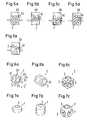
- FIGS. 8a to 8dshow further embodiments of supporting bodies 2 with polyhedron-shaped outer contours, the illustrated supporting bodies 2 having no cavity 3. However, the support body 2 could also have a cavity 3.
- FIG. 8ashows a tetrahedron
- FIG. 8bshows an octahedron
- FIG. 8cshows an icosahedron
- FIG. 8dshows a small star dodecahedron.
- the support body 2as shown in Figure 6a an outer diameter D and an orthogonal to height H, wherein the outer diameter D is preferably at least 1.5 times the height H.
- the support bodies 2have a surface designed in such a way that between the surfaces in the Bone interior 4a filled support bodies 2 a mutual wedging or jamming occurs to form within the bone interior 4a a preferably continuous support structure.
- the surface of the support body 2therefore preferably has shapes from the group corner, edge, tip, recess, opening or a combination thereof, to effect a mutual wedging and jamming of the support body 2.
- the support body 2as shown in Figure 6a, a nut similar shape, with a polygonal outer contour with mutually wedge-shaped surfaces 2f and 2d prominent edges and corners 2e, and an inner cavity 3 with an opening 2c with a relatively large Diameter.
- FIG. 9shows a bone cavity 4b only partially filled with such screw-nut-shaped support bodies 2. From this arrangement, the support body 2 can be seen how they wedge each other by the outer contour partially penetrates through the opening 2c in the inner cavity 3, so that the support body 2 wedge each other, and thus form a mechanically at least contiguous support structure. As soon as the entire bone cavity 4b has been completely filled with these support bodies 2, the support structure formed in this way can essentially bear the load acting from outside on the bone 4 as a composite.
- Figure 14shows a broken bone 4 with a bone missing at the fracture site. This site is covered with a bone plate 10, so that a bone cavity 4b is formed. Also, such a bone cavity 4b can be filled with the above-described filler 1 comprising support body 2.
- FIG. 10shows a fixed cannula 6 with a cannula tip 6a designed as a cutting thread 6c.
- a Kirschner wire 8Within the cannula 6 runs a Kirschner wire 8.
- the Kirschner wire 8is pushed into the bone 4 in order to determine the course direction of the cannula 6.
- the tip 6a of the cannula 6is screwed into the bone 4 using the handle 7 with a rotating motion, so that the tip 6a, and thus the cannula 6, is firmly anchored in the bone 4.
- the handle 7is removed.
- 11shows the cannula 6 with the handle 7 removed.
- the cannula 6comprises a connection part 6b for the handle 7 or for a pressing device 9.
- FIG. 12shows an embodiment of a tip 6a of the cannula 6 in detail.
- the tip 6ahas protruding cutting bodies 6e and an external thread 6d.
- FIG. 13shows a pressing device 9, which is connected to the cannula 6 via the connecting part 6b. Before joining, the cannula 6 was filled with supporting bodies 2.
- the pressing device 9comprises a handle 9a and an actuating handle 9b, which acts on a plunger 9c in such a way that it moves into the cannula 6 a little bit with each actuation, so that the plunger 9c acting on the supporting body 2 projects in the cannula 6 arranged supporting body 2 presses into the bone 4.
- the support bodies 2flow in such a way into the bone 4, also form therein a bone cavity 4b due to the pressure, and fill it with support bodies 2, so that a support structure is formed within the bone 4.
- the position of the plunger 9ccan be read by means of markings 6f attached to the cannula 6, from which it can be deduced how many supporting bodies 2 were pressed into the bone 4.
- the support bodies 2could also be arranged in an additional cannula, which is introduced into the cannula 6 before the pressing device 9 is connected to the cannula 6.
- a second cannulawhich contains the support body 2, would be arranged within the cannula 6. In this way, the cannula 6 could very easily be charged with the support bodies 2.
- the cannula containing the support bodies 2must have an inner diameter adapted to the size of the support body 2 such that the support bodies 2 are arranged following one another and displaceable therein only to sequentially supply the support bodies 2 to the internal bone space 4a. After filling the internal bone space 4a, the pressing device 9 and the cannula 6 are removed and the hole in the bone, as shown in Figure 4, closed with a plug 4c.
- the cannula 6can not only, as shown in Figures 10 to 13, have a round inner cross-section, but also other cross-sectional shapes, for example, as shown in Figure 15 a hexagonal or as shown in Figure 16 a rectangular inner cross-section, for example, for inserting the in Figure 6a shown supporting body 2 are suitable.
- the cannula 6may also have further, adapted to the respective contour of the support body 2 used cross-sectional shapes.
- the tip 6a of the cannula 6can also be configured without fastening means 6c.
- the support bodies 2, as shown in FIG. 2can also be supplied to the bone cavity 4b with a device 9 similar to a syringe.
- a group of support bodiesfor example 5 or 10 support bodies, are subsequently supplied to the bone cavity 4b one after the other, after which the cannula 6 is removed, and with the help of a stuffing tool which is located in the bone cavity 4b support body 2 is additionally pressed and compressed, then again attach the cannula to the bone 4, and introduce another group of support bodies 2 in the bone cavity 4b, and this in turn to compress the stuffing tool.
- an osteoinductive and / or osteoconductive substanceis supplied, for example as a liquid or as a fluid, to fill the remaining cavities in the internal bone space 4a with this substance.
- the filler 1could also be supplied together with a fluid to the bone interior 4a, for example by the support body 2 together with a fluid, in particular mixed, in the pressing device 9 for insertion into the bone interior 4a ready.
Landscapes
- Health & Medical Sciences (AREA)
- Orthopedic Medicine & Surgery (AREA)
- Life Sciences & Earth Sciences (AREA)
- Surgery (AREA)
- Neurology (AREA)
- Molecular Biology (AREA)
- General Health & Medical Sciences (AREA)
- Biomedical Technology (AREA)
- Heart & Thoracic Surgery (AREA)
- Medical Informatics (AREA)
- Nuclear Medicine, Radiotherapy & Molecular Imaging (AREA)
- Animal Behavior & Ethology (AREA)
- Engineering & Computer Science (AREA)
- Public Health (AREA)
- Veterinary Medicine (AREA)
- Prostheses (AREA)
- Surgical Instruments (AREA)
- Orthopedics, Nursing, And Contraception (AREA)
- Toys (AREA)
- Filling Of Jars Or Cans And Processes For Cleaning And Sealing Jars (AREA)
- Moulding By Coating Moulds (AREA)
Abstract
Description
Translated fromGermanDie vorliegende Erfindung betrifft ein Füllmittel zum Ausbilden einer Stützstruktur in einem Knocheninnenraum gemäss dem Oberbegriff von Anspruch 1. Die Erfindung betrifft weiter eine Zuführvorrichtung zum Einfüllen eines Füllmittels in einen Knocheninnenraum gemäss dem Oberbegriff von Anspruch 17. Die Erfindung betrifft weiter ein Verfahren zum Füllen eines Knocheninnenraumes mit einer Stützstruktur gemäss dem Oberbegriff von Anspruch 21.The present invention relates to a filler for forming a support structure in a bone interior according to the preamble of claim 1. The invention further relates to a delivery device for filling a filler into a bone interior according to the preamble of claim 17. The invention further relates to a method for filling a bone interior with a support structure according to the preamble of claim 21.
Die Erfindung bezieht sich auf die Behandlung von Knochen bei Menschen oder Tieren.The invention relates to the treatment of bone in humans or animals.
Die zunehmende Alterung der Gesellschaft führt zu einer überdurchschnittlichen Zunahme von Erkrankungen des Bewegungs- und Stützapparates, insbesondere der Knochen. Knochen können auf unterschiedlichste Arten geschädigt oder geschwächt werden, beispielsweise durch Trauma, Infektion, Abnutzung, Tumorwachstum oder degenerative Krankheiten wie Osteoporose. Bei älteren Menschen stellt insbesondere die Osteoporose, das heisst der Abbau der Spongiosa, ein Problem dar, weil dadurch die Belastungsfähigkeit des Knochens geschwächt wird, was zur Folge hat, dass vermehrt Knochenbrüche auftreten, vor allem an der Wirbelsäule, am Schenkelhals und am Handgelenk. Eine Behandlung derartiger Knochenbrüche ist schwierig, insbesondere wenn degenerative Veränderungen im fortgeschrittenen Stadium vorliegen. Zur Fixation derartiger Knochenbrüche werden üblicherweise äussere oder innere Schienungen (Platte, Schrauben, Implantate) verwendet, welche den Knochen bis zu dessen Heilung zusammenhalten. Derartige Schienen sind jedoch nicht bei allen Knochen verwendbar. So wird beispielsweise bei der Wirbelsäule zur Behandlung eines degenerierten oder eingebrochenen Wirbelkörpers die sogenannte Vertebroplastie angewandt, indem der geschädigte Wirbelkörper mit Knochenzement gefüllt wird. Die Verwendung von Knochenzement bei Wirbelkörpern weist jedoch verschiedene Nachteile auf, insbesondere dass der Knochenzement über Venen oder kleine Knochendefekte im Wirbelkörper unkontrolliert austreten kann, und dadurch Schäden in den benachbarten anatomischen Strukturen verursachen kann, beispielsweise bei einem Austritt in den Spinalkanal. Weitere Nachteile von Knochenzement sind, dass sich dieser beim Aushärten stark erwärmt, was umliegendes Gewebe oder sogar Nerven schädigen kann, dass der Knochenzement sehr schnell verarbeitet werden muss, dass im Knochenzement kein Knochen nachwachsen kann, und dass der Knochenzement mit der Zeit spröde wird.The increasing aging of society leads to an above-average increase in diseases of the musculoskeletal system, especially the bones. Bones can be damaged or weakened in a variety of ways, including trauma, infection, wear, tumor growth or degenerative diseases such as osteoporosis. In older people, osteoporosis, ie the removal of cancellous bone, is a problem because it weakens the load capacity of the bone, As a result, fractures occur more frequently, especially at the spine, femoral neck and wrist. Treatment of such fractures is difficult, especially when degenerative changes are advanced. For fixation of such bone fractures usually outer or inner splints (plate, screws, implants) are used, which hold the bone until its healing. However, such rails are not suitable for all bones. Thus, for example, the so-called vertebroplasty is applied to the spinal column for treating a degenerated or buried vertebral body by filling the damaged vertebral body with bone cement. The use of bone cement in vertebral bodies, however, has several disadvantages, in particular that the bone cement can escape via veins or small bone defects in the vertebral body uncontrolled, and thereby cause damage in the adjacent anatomical structures, for example, in an exit into the spinal canal. Other disadvantages of bone cement are that it heats up strongly during curing, which can damage surrounding tissue or even nerves, that the bone cement must be processed very quickly, that no bone can regrow in the bone cement, and that the bone cement becomes brittle over time.
Die Druckschrift US 2004/0052829 offenbart ein Verfahren zur Behandlung poröser Wirbelkörper, insbesondere von Wirbelkörpern mit Osteoporosefraktur. Dazu wird eine biokompatible, flüssige Trägersubstanz wie Wasser verwendet, welche mit biokompatiblen Stützkörpern angereichert ist. Nachteilig an diesem Verfahren ist die Tatsache, dass ein ballonartiger Behälter erforderlich ist, welcher zuerst in den Wirbelkörper einzubringen ist, und welcher danach mit der Trägersubstanz enthaltend die Stützkörper gefüllt wird. Der ballonartige Behälter ist erforderlich um sicherzustellen, dass sowohl die flüssige Trägersubstanz als auch die darin enthaltenen Stützkörper innerhalb des Wirbelkörpers verbleiben. Würde kein ballonartiger Behälter verwendet, so bestünde auch bei diesem Verfahren die bekannte Gefahr des Ausfliessens, indem die flüssige Trägersubstanz sowie die darin enthaltenen Stützkörper, welche eine Grösse im Mikrometerbereich aufweisen, aus dem geschädigten Wirbelkörper entweichen, und auf unkontrollierbare Art benachbartes Gewebe schädigen oder sich im menschlichen Körper ausbreiten. Das bekannte Verfahren weist somit die Nachteile auf, dass es aufwendig ist den ballonartigen Behälter in den Wirbelkörper einzubringen, dass dieser beim Einbringen oder durch die Stützkörper beschädigt werden kann, sodass die Trägersubstanz ausfliessen könnte, und dass der Wirbelkörper nicht optimal füllbar ist, da sich der ballonartige Behälter während dem Zuleiten der flüssigen Trägersubstanz "aufbläst", und somit mehr Volumen als für die Stützkörper an sich erforderlich beansprucht.The publication US 2004/0052829 discloses a method for the treatment of porous vertebral bodies, in particular of vertebral bodies with Osteoporosefraktur. For this purpose, a biocompatible, liquid carrier substance such as water is used, which is enriched with biocompatible supportive bodies. A disadvantage of this method is the fact that a balloon-like container is required, which is first to be introduced into the vertebral body, and which is then filled with the carrier substance containing the support body. The balloon-like container is required to ensure that both the liquid carrier and the support bodies contained therein remain within the vertebral body. If no balloon-type container were used, the known risk of outflow would also be present in this method in that the liquid carrier substance and the support bodies contained therein, which have a size in the micrometer range, escape from the damaged vertebral body and damage adjacent tissue in an uncontrollable manner spread in the human body. The known method thus has the disadvantages that it is costly to introduce the balloon-like container into the vertebral body that it may be damaged during insertion or by the support body, so that the carrier substance could flow out, and that the vertebral body is not optimally fillable, since the balloon-like container "inflates" during the supply of the liquid carrier, and thus claimed more volume than required for the support body itself.
Es ist daher Aufgabe der vorliegenden Erfindung ein vorteilhafteres, implantierbares, insbesondere injizierbares Füllmittel vorzuschlagen, welches defekte Knochen, insbesondere Wirbelkörper, derart optimal zu versorgen erlaubt, dass die Knochen vom Zeitpunkt der Implantation an fähig sind die anliegenden physiologischen Lasten zu tragen.It is therefore an object of the present invention to propose a more advantageous, implantable, in particular injectable, filler which allows defective bones, in particular vertebral bodies, to be optimally supplied in such a way that, from the time of implantation, the bones are capable of bearing the applied physiological loads.
Diese Aufgabe wird gelöst mit einem trockenfliessfähigen Füllmittel aufweisend die Merkmale von Anspruch 1. Die Unteransprüche 2 bis 17 betreffen weitere vorteilhaft ausgestaltete Füllmittel. Die Aufgabe wird weiter gelöst mit einer Zuführvorrichtung zum Einführung des Füllmittels aufweisend die Merkmale von Anspruch 18. Die Unteransprüche 19 und 20 betreffen weitere vorteilhafte Ausgestaltungen. Die Aufgabe wird weiter gelöst mit einem Verfahren zum Füllen eines Knocheninnenraumes mit Stützkörpern aufweisend die Merkmale von Anspruch 21. Die Unteransprüche 22 bis 26 betreffen weitere, vorteilhafte Verfahrensschritte.This object is achieved with a dry flowable filler having the features of claim 1. The dependent claims 2 to 17 relate to further advantageously configured fillers. The task is further solved with a feed device for introducing the filler having the features of claim 18. The
Die Aufgabe wird insbesondere gelöst mit einem trockenfliessfähigen Füllmittel zum Ausbilden einer Stützstruktur in einem Knocheninnenraum, wobei das Füllmittel eine Mehrzahl biokompatibler Stützkörper umfasst, welche unter den üblicherweise im Knocheninnenraum auftretenden physiologischen Lasten resistent gegen Verformung oder Bruch sind, wobei die Stützkörper eine Grösse zwischen 2 mm und 10 mm aufweisen.The object is achieved in particular with a dry-flowable filler for forming a support structure in a bone interior, wherein the filler comprises a plurality of biocompatible support bodies, which are resistant to deformation or fracture under the physiological loads usually occurring in the bone interior, wherein the support body has a size between 2 mm and 10 mm.
Der Ausdruck "trockenfliessfähig" bedeutet, dass das Füllmittel injizierbar ist, jedoch ohne Verwendung irgendeiner fluiden Trägersubstanz, welche den Stützkörpern Fliesseigenschaften verleihen könnte. Die Stützkörper sind derart gross gewählt, dass diese, zum Beispiel in einer Kanüle hintereinander liegend angeordnet, alle gemeinsam in der Kanüle verschiebbar sind, indem auf den hintersten Stützkörper ein Druck ausgeübt wird, und diese Kraft auf alle sich in der Kanüle befindlichen Stützkörper übertragen wird, sodass die Stützkörper in der Kanüle zur Kanülenspitze hin bewegt werden. Diese Stützkörper weisen trockenfliessfähige Eigenschaften auf, indem diese in der Kanüle ohne eine Trägersubstanz eine Art fliessende Eigenschaften aufweisen, indem die Stützkörper, ähnlich einer Injektion, über die Kanüle einem Knocheninnenraum zuführbar sind.The term "dry-flowable" means that the filler is injectable, but without the use of any fluid carrier which could impart flow properties to the support bodies. The support bodies are chosen so large that they, for example, arranged in a cannula lying one behind the other, all together in the cannula are displaceable by a pressure is exerted on the rearmost support body, and this force is transmitted to all located in the cannula support body so that the support bodies in the cannula are moved toward the cannula tip. These support bodies have dry-flow properties in that they have a kind of flowing properties in the cannula without a carrier substance in that the support bodies, similar to an injection, can be supplied to a bone interior via the cannula.
Der Ausdruck "Stützkörper" bezeichnet einen Körper, welcher die in einem Knocheninnenraum, insbesondere die in einem Wirbelkörper auftretenden Kräfte zu tragen vermag, ohne wesentlich verformt oder gar zerstört zu werden. Es sind eine Vielzahl von biokompatibler Werkstoffe bekannt, aus welchen ein derartiger Stützkörper gefertigt sein kann. Beispielsweise könnte der Stützkörper gefertigt sein aus:
- keramischen Werkstoffen, insbesondere Calciumphosphate /Hydroxylapatite, Aluminiumoxide, Zirkoniumoxide, ATZ Geramk (Alu-Zirkonium-Oxid), bioaktive Gläser, Glaskeramiken, Porzellan oder einer Kombination davon, oder
- metallischen Werkstoffen, insbesondere Titan, Tantal, rostfreier Stahl, Stahllegierungen wie Kobalt-Chrom Legierung, Titanlegierungen wie Titan-Nickel Legierung oder Titan-Aluminium-Niobium/Vanadium Legierung, oder einer Kombination davon, oder
- Polymeren, insbesondere Polymethylmethacryl (PMMA), Polyetheretherketon (PEEK) Polyethylen (PE), Polyethylenterephthalat (PET), oder einer Kombination davon, oder
- biodegradablen Polymeren wie Polylactate.
- ceramic materials, in particular calcium phosphates / hydroxylapatites, aluminum oxides, zirconium oxides, ATZ Geramk (aluminum zirconium oxide), bioactive glasses, glass ceramics, porcelain or a combination thereof, or
- metallic materials, in particular titanium, tantalum, stainless steel, steel alloys such as cobalt-chromium alloy, titanium alloys such as titanium-nickel alloy or titanium-aluminum-niobium / vanadium alloy, or a combination thereof, or
- Polymers, in particular polymethylmethacryl (PMMA), polyetheretherketone (PEEK) polyethylene (PE), polyethylene terephthalate (PET), or a combination thereof, or
- biodegradable polymers such as polylactates.
Das erfindungsgemässe Füllmittel umfassend eine Mehrzahl biokompatibler Stützkörper weist die Vorteile auf, dass kein Ballon oder ein anderes Begrenzungsmittel im Knocheninnenraum erforderlich ist, da das Füllmittel einerseits keine Trägersubstanz wie eine Flüssigkeit aufweist, welche auslaufen könnte, und da das Füllmittel andererseits aus einzelnen, relativ grossen Stützkörpern besteht, welche auf Grund ihrer Grösse auch einem stark geschädigten Wirbelkörper kaum unkontrolliert entwichen können, und sich zudem auf Grund ihrer Grösse nicht unkontrolliert im Körper verteilen können. Das erfindungsgemässe Füllmittel ist trockenfliessfähig und kann daher mit Hilfe einer Kanüle in einen Knocheninnenraum injiziert werden. Das erfindungsgemässe Füllmittel ist daher insbesondere auch zur Versorgung schwer zugänglicher Knochen wie der Wirbelknochen geeignet.The filler according to the invention comprising a plurality of biocompatible support bodies has the advantages that no balloon or other limiting means in the bone interior is required because the filler on the one hand has no carrier substance such as a liquid that could leak, and because the filler on the other hand from individual, relatively large Support bodies exists, which can escape due to their size even a severely damaged vertebral body uncontrollably, and also due to their size can not be distributed uncontrollably in the body. The inventive filler is dry flowable and can therefore be injected by means of a cannula in a bone interior. The filler according to the invention is therefore particularly suitable for the treatment of hard-to-reach bones such as the vertebral bone.
In einer besonders vorteilhaften Ausführungsform sind die Stützkörper derart ausgestaltet, dass sie sich gegenseitig verkeilen können, sodass die sich im Knocheninnenraum befindlichen Stützkörper gegenseitig verkeilen und dadurch eine zusammenhängende Stützstruktur bilden.In a particularly advantageous embodiment, the support bodies are designed such that they can wedge each other, so that the support body located in the bone interior wedge each other and thereby form a coherent support structure.
Das erfindungsgemässe Füllmittel erlaubt den Knochendefekt frakturierter Knochen, insbesondere Wirbelkörper, mit einer Stützstruktur bestehend aus einzelnen Stützkörpern zu füllen. Diese Stützstruktur verleiht dem Knochen eine Stabilität, überträgt auftretende Kräfte, und kann zudem die Knochenheilung und/oder die Knochenbildung anregen. Die Stützkörper können zudem mit knochenheilenden und/oder knochenbildenden Substanzen gefüllt und/oder beschichtet sein oder eine knochenheilende und/oder knochenbildende Oberflächenstruktur aufweisen. Das erfindungsgemässe Füllmittel ist mittels einer kleinen Kanüle in den Knochen einbringbar, was einen schonenden Zugang zum Knochen ermöglicht.The filler according to the invention allows the bone defect of fractured bones, in particular vertebral bodies, to be filled with a support structure consisting of individual supporting bodies. This support structure provides stability to the bone, transmits forces, and may also promote bone healing and / or bone formation. The support bodies can also be filled and / or coated with bone-healing and / or bone-forming substances or have a bone-healing and / or bone-forming surface structure. The filler according to the invention can be introduced into the bone by means of a small cannula, which allows a gentle access to the bone.
Die Erfindung wird nachfolgend an Hand von Figuren im Detail beschrieben. Es zeigen:
- Fig. 1
- eine Aufsicht auf einen Wirbelkörper mit einer eingeführten Kanüle;
- Fig. 2
- einen Schnitt durch einen Wirbelkörper, in welchen das Füllmittel eingeführt wird;
- Fig. 3
- einen Schnitt durch den Wirbelkörper sowie die Kanüle gemäss Fig. 2;
- Fig. 4
- einen Schnitt durch den Wirbelkörper mit vollständig eingeführtem Füllmittel;
- Fig. 5a bis 5e
- schematische Darstellungen unterschiedlich ausgebildeter Stützstrukturen;
- Fig. 6a bis 6c
- Stützkörper mit eckigen Aussenkonturen;
- Fig. 7a bis 7c
- Stützkörper mit abgerundeten Aussenkonturen;
- Fig. 8a bis 8d
- Stützkörper mit polyederförmigen Aussenkonturen;
- Fig. 9
- ein weiteres Ausführungsbeispiel eines teilweise mit Füllmittel gefüllten Knochenhohlraumes;
- Fig. 10
- das Befestigen einer Kanüle in einem Knochen;
- Fig. 11
- eine Kanüle;
- Fig. 12
- eine Kanülenspitze;
- Fig. 13
- eine Pressvorrichtung;
- Fig. 14
- ein gebrochener Knochen mit Knochenhohlraum;
- Fig. 15
- ein Querschnitt durch eine Kanüle;
- Fig. 16
- ein weiterer Querschnitt durch eine Kanüle.
- Fig. 1
- a plan view of a vertebral body with an inserted cannula;
- Fig. 2
- a section through a vertebral body, in which the filler is introduced;
- Fig. 3
- a section through the vertebral body and the cannula of FIG. 2;
- Fig. 4
- a section through the vertebral body with fully introduced filler;
- Fig. 5a to 5e
- schematic representations of differently shaped support structures;
- Fig. 6a to 6c
- Supporting body with angular outer contours;
- Fig. 7a to 7c
- Supporting body with rounded outer contours;
- Fig. 8a to 8d
- Supporting body with polyhedron-shaped outer contours;
- Fig. 9
- another embodiment of a partially filled with filler bone cavity;
- Fig. 10
- attaching a cannula in a bone;
- Fig. 11
- a cannula;
- Fig. 12
- a cannula tip;
- Fig. 13
- a pressing device;
- Fig. 14
- a broken bone with a bone cavity;
- Fig. 15
- a cross section through a cannula;
- Fig. 16
- another cross section through a cannula.
Figur 1 zeigt in einer Aufsicht einen Knochen 4, spezifischer einen Wirbelkörper mit einem Knocheninnenraum 4a. Unter dem Begriff Knocheninnenraum 4a wird das gesamte, vom Knochen 4 eingenommene Volumen verstanden. Im Knocheninnenraum 4a befindet sich ein Knochenhohlraum 4b, in welchen eine Kanüle 6 mündet. Der Knochenhohlraum 4b kann beispielsweise auf Grund degenerativer Vorgänge, insbesondere Osteoporose, entstanden sein. Der Knochenhohlraum 4b kann mit einem geeigneten Instrument auch künstlich erzeugt oder vergrössert werden.FIG. 1 shows in a plan view a
Figur 2 zeigt einen Wirbelkörper 4 mit einem Knocheninnenraum 4a sowie eine Zuführvorrichtung 5 umfassend eine Kanüle 6, eine Pressvorrichtung 9 mit Betätigungsgriff 9b und einem Stössel 9c. Die Kanüle 6 münden in den Knocheninnenraum 4a, welcher in diesem Ausführungsbeispiel keinen Knochenhohlraum 4b aufweist. Im Innenraum der Kanüle 6 und der Pressvorrichtung 9 sind biokompatible Stützkörper 2 hintereinander liegend und sich im wesentlichen gegenseitig berührend angeordnet, sodass der auf den zuhinterst liegenden Stützkörper 2 wirkende Stössel 9c alle Stützkörper 2 in Richtung Knocheninnenraum 4a treibt. Dies ermöglicht, falls erforderlich, über die Stützkörper 2 die am Betätigungsgriff 9b anliegende Kraft bis zu den sich an der Spitze der Kanüle 6 befindlichen Stützkörpern 2 zu übertragen, sodass diese mit einer entsprechenden Kraft in den Knocheninnenraum 4a eindringen, und dabei während dem Eindringen einen Knochenhohlraum 4b ausbilden. Der Innendurchmesser der Kanüle 6 sowie der Pressvorrichtung 9 sind bezüglich dem Aussendurchmesser der Stützkörper 2 derart angepasst ausgestaltet, dass die Stützkörper 2 in Flussrichtung, d.h. zur Austrittsöffnung der Kanüle 6 hin, hintereinanderliegend angeordnet sind, was zur Folge hat, dass die Gesamtheit der Stützkörper 2 ein trockenfliessfähiges Füllmittel 1 bilden, welches ohne jegliche Schmiermittel fliessähnliche Eigenschaften aufweist, indem die Stützkörper 2 mit einer wie in Figur 2 dargestellt spritzenähnlichen Vorrichtung dem Knocheninnenraum 4a zuführbar ist. Die Kanüle 6 könnte auch gekrümmt verlaufen, oder aus einem flexiblen oder festen Material bestehen.FIG. 2 shows a
Der in Figur 3 in einem Schnitt dargestellte Wirbelkörper 4 weist einen Knochenhohlraum 4b auf, welcher vorgängig, vor dem Einführen der Stützkörper 2, mit einem speziellen Instrument erzeugt wurde. Danach wird die Spitze 6a der Kanüle 6 bis zum Knochenhohlraum 4b vorgetrieben, und danach die in einer Seitenansicht dargestellten Stützkörper 2 einzeln und nacheinander folgend zugeführt, sodass sich diese zufällig im Knochenhohlraum 4b verteilen. Die Kanüle 6 weist einen runden Innenquerschnitt auf, sodass jeder Stützkörper 2, welche alle identisch ausgestaltet sind, eine längliche, sphärisch verlaufende Aussenkontur aufweist. Der Stützkörper 2 weist eine maximale Dimension zwischen 2 mm und 10 mm auf. Die Stützkörper 2 sind als Vollkörper ausgestaltet. Alle Stützkörper 2 sind betreffend Dimension und Form identisch ausgestaltet.The
Figur 4 zeigt den in Figur 3 dargestellten Wirbelkörper 4 mit einem vollständig durch Stützkörper 2 gefüllten Knochenhohlraum 4b, wobei die Stützkörper 2 an unterschiedlichen Stelle aufeinander aufliegen und dabei im Knochenhohlraum 4b gefangen sind, sodass die Gesamtheit dieser Stützkörper 2 eine tragfähige Stützstruktur bilden. Der Zugangskanal zum Knochenhohlraum 4b wurde nach dem Einführen der Stützkörper 2 mit einem Zapfen 4c verschlossen.FIG. 4 shows the
Ein Knocheninnenraum 4a beziehungsweise ein Knochenhohlraum 4b kann mit unterschiedlichst ausgestalteten Stützkörpern 2 gefüllt werden. Figur 5a zeigt schematisch einen begrenzten Knochenhohlraum 4b mit Einlassöffnung 4c, durch welche die kugelförmigen Stützkörper 2 eingeführt werden. Figur 5b zeigt ellipsoidförmig ausgestaltete Stützkörper 2. Ein Vorteil der in den Figuren 5a und 5b dargestellten Stützkörpern 2 mit sphärischer Aussenkontur ist die Tatsache, dass sie unter geringem Kraftaufwand gegenseitig verschiebbar sind, sodass diese Stützkörper 2 das Volumen des Knochenhohlraumes 4b sehr gut ausfüllen. Die Figuren 5c und 5d zeigen Stützkörper 2 mit einer kantigen Aussenkontur, wobei die unter einem Winkel zusammenlaufenden Seitenflächen der Stützkörper 2 eine Keilwirkung ausüben können, sodass sich die im begrenzten Knochenhohlraum 4b befindlichen Stützkörper 2 in einer vorteilhaften Ausführungsform, wie in Figur 5c dargestellt, gegenseitig verkeilen, wobei sich zwischen dem Stützkörper 2 grössere Zwischenräume ergeben, in welche der Knochen nachwachsen kann. Die Gesamtheit der Stützkörper 2 bilden wiederum eine mechanisch belastbare Stützstruktur. Im Gegensatz zu den in den Figuren 5a bis 5d dargestellten Stützkörpern 2, welche jeweils bezüglich ihrer Form und Grösse identisch sind, könnten die Stützkörper 2, wie in Figur 5e dargestellt, innerhalb des Knochenhohlraumes 4b auch unterschiedliche Formen und/oder Grössen aufweisen.An internal bone space 4a or a
Die Figuren 6a, 6b und 6c sowie 7a, 7b und 7c zeigen Stützkörper 2 mit einem offenen Innenhohlraum 3. Unter einem offenen Innenhohlraum 3 wird ein Hohlraum im Stützkörper 2 verstanden, welcher gegen Aussen offen ist, im Gegensatz zu einem geschlossenen Hohlraum, welcher vollständig im Innern des Stützkörpers 2 angeordnet ist, ohne eine Öffnung nach Aussen aufzuweisen. Auch diese Stützkörper 2 weisen eine maximale Grösse im Bereich zwischen 2 mm und 10 mm auf. Jeder Stützkörper 2 umfasst ein Gesamtvolumen, welches dem Volumen des Materials des Stützkörpers 2 sowie dessen Innenhohlraum 3 entspricht. Das Volumen des Innenhohlraumes ist grösser als 30% des Gesamtvolumens, vorzugsweise grösser als 50% und kann bis zu 90% betragen. Die Grösse des maximal möglichen Volumens des Innenhohlraumes 3 ist abhängig von den maximal am Stützkörper 2 angreifenden Druckkräften. Diese Druckkräfte sind abhängig vom spezifischen Knocheninnenraum 4a beziehungsweise von Knochen 4, in welchem die Stützstruktur gebildet wird. Die Tragfähigkeit des Stützkörpers 2 ist natürlich abhängig vom verwendeten Material. Wird der Stützkörper 2 beispielsweise aus Metall gebildet, so kann der Innenhohlraum 3 relativ gross ausgebildet sein, und der Stützkörper 2 trotzdem resistent gegen die angreifenden Druckkräfte sein. Ist der Stützkörper 2 aus einem Material wie Bioglas oder einer resorbierbaren Substanz gefertigt, so muss der Innenhohlraum 3 entsprechend den Materialeigenschaften prozentual kleiner ausgebildet sein, um dem Stützkörper 2 eine genügend grosse Tragkraft zu verleihen. Dieser Innenhohlraum 3, insbesondere ein prozentual relativ grosser Innenhohlraum 3, weist den Vorteil auf, dass dieser mit der Zeit von nachwachsendem Knochenmaterial gefüllt werden kann. In einer besonders vorteilhaften Ausgestaltung wird der Innenhohlraum 3 des Stützkörpers 2 vor dessen Einführen zumindest teilweise mit einer osteoinduktiven und/oder osteokonduktiven Substanz gefüllt, insbesondere einem knochenwachstumsfördernden Protein oder Kalziumsulfat oder einer Kombination dieser oder weiterer Substanzen. Dank derart gefüllten Stützkörpern 2 ist es möglich dem Knocheninnenraum 4a mittels dem trockenfliessfähigen Füllmitteln 1, bestehend aus einer Vielzahl von Stützkörpern 2, sowohl eine Stützstruktur als auch osteoinduktive und/oder osteokonduktive Substanzen zuzuführen. Diese Ausgestaltung weist die Vorteile auf, dass das Füllmittel 1 trocken dem Knocheninnenraum 4a zugeführt wird, sodass keine Gefahr eines Auslaufens durch eventuell im Knochen 4 vorhandene Ritzen, Spalten und Öffnungen besteht. Zudem bewirkt die osteoinduktive Substanz ein Knochenwachstum, sodass die Hohlräume 3 und die sich zwischen den Stützkörpern 2 ergebenden Zwischenräume vorteilhafterweise zunehmend mit nachwachsendem Knochen gefüllt werden. Da die Stützkörper 2 im Knocheninnenraum 4a zufällig ausgerichtet angeordnet sind, das heist die Hohlräume 3 in zufälligen Richtungen verlaufen, und auch die Zwischenräume in zufälligen Richtungen verlaufen und eine durch den Zufall bestimmte Grösse aufweisen, bilden die Stützkörper 2 an sich, insbesondere wenn das Volumen des Innenhohlraumes 3 mehr als 50% des Gesamtvolumens beträgt, eine im weitesten Sinne Spongiosa ähnliche Stützstruktur. Wenn mit zunehmendem Heilungsverlauf zudem die Hohlräume 3 und die Zwischenräume mit nachwachsender Spongiosa gefüllt werden, so bildet sich im Knocheninnenraum 4a eine dem gesunden Knochen teilweise vergleichbare Stützstruktur aus, mit willkürlich ausgerichteten Stützkörpern 2, deren Hohl- und Zwischenräume mit Spongiosa verwachsen sind.Figures 6a, 6b and 6c and 7a, 7b and 7c show
Der Innenhohlraum 3 der Stützkörper 2 gemäss der Figuren 6a,6b,6c,7a,7b,7c ist zusammenhängend und nicht porös ausgestaltet, sodass die Innenkontur 2b seitlich einen relativ grossen Innenhohlraum 3 begrenzt. Der Innenhohlraum 3 gemäss der Figuren 6a,6b,7a,7b ist zylinderförmig ausgestaltet und weist eine kreisförmige Öffnung 2c auf. Die Stützkörper 2 gemäss den Figuren 6a, 7a sind im wesentlichen ringförmig ausgestaltet, wobei die Ausführungsform gemäss Figur 6a in Umfangsrichtung eine polyederförmige Aussenkontur bestehend aus sechs gegenseitig keilförmig verlaufenden Oberflächen 2f aufweist, welche sich jeweils in einer Kante 2d bzw. Ecke 2e treffen. Der Stützkörper 2 weist in Umfangsrichtung vorzugsweise eine 3- bis 10-eckige Aussenkontur auf, insbesondere eine 4-, 5- oder 6-eckige Aussenkontur. Die Ausführungsform gemäss Figur 7a weist in Umfangsrichtung eine sphärisch, insbesondere kugelförmig oder ellipsoidförmig verlaufende Aussenkontur auf. Die Stützkörper 2 gemäss den Figuren 6b und 7b sind im wesentlichen hohlzylinderförmig ausgestaltet. Die Stützkörper 2 gemäss den Figuren 6c und 7c weisen im wesentlichen eine würfelförmige bzw. sphärisch verlaufende Aussenkontur auf. Die Figuren 8a bis 8d zeigen weitere Ausführungsform von Stützkörpern 2 mit polyederförmig verlaufenden Aussenkonturen auf, wobei die dargestellten Stützkörper 2 keinen Hohlraum 3 aufweisen. Die Stützkörper 2 könnten jedoch auch einen Hohlraum 3 aufweisen. Figur 8a zeigt ein Tetraeder, Figur 8b ein Oktaeder, Figur 8c ein Ikosaeder und Figur 8d ein kleines Sternendodekaeder.The
In einer vorteilhaften Ausgestaltung weist der Stützkörper 2, wie in Figur 6a dargestellt einen Aussendurchmesser D und eine dazu orthogonale Höhe H auf, wobei der Aussendurchmesser D vorzugsweise zumindest das 1,5-fache der Höhe H beträgt. Die Stützkörper 2 weisen in einer vorteilhaften Ausgestaltung eine derart ausgebildete Oberfläche auf, dass zwischen den im Knocheninnenraum 4a eingefüllten Stützkörpern 2 ein gegenseitiges Verkeilen beziehungsweise Verklemmen auftritt, um innerhalb des Knocheninnenraumes 4a eine vorzugsweise zusammenhängende Stützstruktur zu bilden. Die Oberfläche der Stützkörper 2 weist daher vorzugsweise Formen aus der Gruppe Ecke, Kante, Spitze, Vertiefung, Durchbrechung oder eine Kombination davon auf, um ein gegenseitiges Verkeilen und Verklemmen der Stützkörper 2 zu bewirken. In einer vorteilhaften Ausgestaltung weist der Stützkörper 2, wie in Figur 6a dargestellt, eine Schraubenmutter ähnliche Form auf, mit einer mehreckigen Aussenkontur mit gegenseitig keilförmig verlaufenden Flächen 2f und markanten Kanten 2d und Ecken 2e, sowie einem Innenhohlraum 3 mit einer Öffnung 2c mit relativ grossem Durchmesser. Figur 9 zeigt einen erst teilweise mit derartigen, schraubenmutterförmigen Stützkörpern 2 gefüllten Knochenhohlraum 4b. Aus dieser Anordnung der Stützkörper 2 ist ersichtlich, wie sie sich gegenseitig verkeilen, indem die Aussenkontur über die Öffnung 2c teilweise in den Innenhohlraum 3 eindringt, sodass sich die Stützkörper 2 gegenseitig verkeilen, und derart eine mechanisch zumindest zusammenhängende Stützstruktur ausbilden. Sobald der gesamte Knochenhohlraum 4b vollständig mit diesen Stützkörpern 2 gefüllt ist, kann die derart ausgebildete Stützstruktur die von Aussen auf den Knochen 4 einwirkenden Last im wesentlichen als Verbund tragen.In an advantageous embodiment, the
Figur 14 zeigt einen gebrochenen Knochen 4, wobei an der Bruchstelle ein Knochenteil fehlt. Diese Stelle ist mit einer Knochenplatte 10 abgedeckt, sodass sich ein Knochenhohlraum 4b ausbildet. Auch ein derartiger Knochenhohlraum 4b kann mit dem oben beschriebenen Füllmittel 1 umfassend Stützkörper 2 gefüllt werden.Figure 14 shows a
Figur 10 zeigt eine feste Kanüle 6 mit einer als Schneidgewinde 6c ausgestalteten Kanülenspitze 6a. Innerhalb der Kanüle 6 verläuft ein Kirschnerdraht 8. Vorerst wird der Kirschnerdraht 8 in den Knochen 4 gestossen, um die Verlaufsrichtung der Kanüle 6 zu bestimmen. Danach wird die Spitze 6a der Kanüle 6 unter Verwendung des Handgriffes 7 mit einer rotierenden Bewegung in den Knochen 4 geschraubt, sodass die Spitze 6a und somit die Kanüle 6 fest im Knochen 4 verankert ist. Danach wird der Handgriff 7 abgenommen. Figur 11 zeigt die Kanüle 6 mit entferntem Handgriff 7. Die Kanüle 6 umfasst ein Anschlussteil 6b für den Handgriff 7 beziehungsweise für eine Pressvorrichtung 9. Figur 12 zeigt ein Ausführungsbeispiel einer Spitze 6a der Kanüle 6 im Detail. Die Spitze 6a weist vorstehende Schneidkörper 6e und ein Aussengewinde 6d auf. Figur 13 zeigt eine Pressvorrichtung 9, welche über das Anschlussteil 6b mit der Kanüle 6 verbunden ist. Vor dem Verbinden wurde die Kanüle 6 mit Stützkörpern 2 gefüllt. Die Pressvorrichtung 9 umfasst einen Handgriff 9a sowie einen Betätigungsgriff 9b, welcher derart auf einen Stössel 9c wirkt, dass dieser sich bei jeder Betätigung ein Stück weit in die Kanüle 6 hineinbewegt, sodass der auf die Stützkörper 2 wirkende Stössel 9c die in der Kanüle 6 zuvorderst angeordneten Stützkörper 2 in den Knochen 4 presst. Die Stützkörper 2 fliessen derart in den Knochen 4 hinein, bilden darin auf Grund des Druckes zudem einen Knochenhohlraum 4b aus, und füllen diesen mit Stützkörpern 2, sodass innerhalb des Knochens 4 eine Stützstruktur ausgebildet wird. Die Lage des Stössels 9c kann mit Hilfe von an der Kanüle 6 angebrachten Markierungen 6f abgelesen werden, woraus abgeleitet werden kann wie viele Stützkörper 2 in den Knochen 4 gepresst wurden. Die Stützkörper 2 könnten auch in einer zusätzlichen Kanüle angeordnet sein, welche in die Kanüle 6 eingeführt wird, bevor die Pressvorrichtung 9 mit der Kanüle 6 verbunden wird. Somit wäre innerhalb der Kanüle 6 eine zweite Kanüle angeordnet, welche die Stützkörper 2 enthält. Derart könnte die Kanüle 6 sehr einfach mit den Stützkörpern 2 beschickt werden. Die die Stützkörper 2 enthaltende Kanüle muss einen derart der Grösse der Stützkörper 2 angepassten Innendurchmesser aufweisen, dass die Stützkörper 2 nur nacheinander folgend angeordnet und darin verschiebbar sind, um die Stützkörper 2 nacheinanderfolgend dem Knocheninnenraum 4a zuzuführen. Nach dem Füllen des Knocheninnenraumes 4a wird die Pressvorrichtung 9 und die Kanüle 6 entfernt und das Loch im Knochen, wie in Figur 4 dargestellt, mit einem Pfropfen 4c verschlossen.FIG. 10 shows a fixed
Die Kanüle 6 kann nicht nur, wie in den Figuren 10 bis 13 dargestellt, einen runden Innenquerschnitt aufweisen, sondern auch andere Querschnittsformen, beispielsweise wie in Figur 15 dargestellt einen sechseckigen oder wie in Figur 16 dargestellt einen rechteckigen Innenquerschnitt, welche beispielsweise zum Einführen des in Figur 6a dargestellten Stützkörpers 2 geeignet sind. Die Kanüle 6 kann auch weitere, der jeweiligen Kontur des verwendeten Stützkörpers 2 angepasste Querschnittformen aufweisen.The
Die Spitze 6a der Kanüle 6 kann auch ohne Befestigungsmittel 6c ausgestaltet sein. Insbesondere falls bereits vorgängig ein Knochenhohlraum 4b gebildet wurde, können die Stützkörper 2, wie in Figur 2 dargestellt, auch mit einer Spritzen ähnlichen Vorrichtung 9 dem Knochenhohlraum 4b zugeführt werden. In einem vorteilhaften Verfahren wird nacheinander folgend jeweils eine Gruppe von Stützkörpern, beispielsweise 5 oder 10 Stützkörper, dem Knochenhohlraum 4b zugeführt, danach die Kanüle 6 entfernt, und mit Hilfe eines Stopfwerkzeuges die sich im Knochenhohlraum 4b befindlichen Stützkörper 2 zusätzlich hineingepresst und verdichtet, um danach wieder die Kanüle am Knochen 4 anzusetzen, und eine weitere Gruppe von Stützkörpern 2 in den Knochenhohlraum 4b einzuführen, und diese wiederum mit dem Stopfwerkzeug zu verdichten.The tip 6a of the
In einem möglichen Verfahrensschritt kann, nachdem die Stützkörper 2 in den Knocheninnenraum 4a eingeführt wurden, eine osteoinduktive und/oder osteokonduktive Substanz zugeführt, beispielsweise als Flüssigkeit oder als Fluid, um die noch vorhandenen Hohlräume im Knocheninnenraum 4a mit dieser Substanz zu füllen. Das Füllmittel 1 könnte auch gemeinsam mit einem Fluid dem Knocheninnenraum 4a zugeführt werden, indem beispielsweise die Stützkörper 2 gemeinsam mit einem Fluid, insbesondere gemischt, in der Pressvorrichtung 9 zum Einführen in den Knocheninnenraum 4a bereitstehen.In one possible method step, after the
Claims (26)
Translated fromGermanPriority Applications (11)
| Application Number | Priority Date | Filing Date | Title |
|---|---|---|---|
| EP04405451AEP1623727A1 (en) | 2004-07-14 | 2004-07-14 | Fller and administration device for forming a supportive structure in a bone cavity |
| DE502005011127TDE502005011127D1 (en) | 2004-07-14 | 2005-07-14 | FILLING AND FEEDING DEVICE FOR DEVELOPING A SUPPORT STRUCTURE IN A BONE INTERIOR |
| CA002605062ACA2605062A1 (en) | 2004-07-14 | 2005-07-14 | Filler and supply device for forming a support structure in a bone cavity |
| AT05763584TATE501745T1 (en) | 2004-07-14 | 2005-07-14 | FILLING AGENT AND FEEDING DEVICE FOR FORMING A SUPPORT STRUCTURE IN A BONE INTERIOR |
| CN2005800308651ACN101018574B (en) | 2004-07-14 | 2005-07-14 | Filler, delivery device and system for forming a support structure in an intraosseous space |
| EP05763584AEP1771217B1 (en) | 2004-07-14 | 2005-07-14 | Filler and administration device for forming a supportive structure in a bone cavity |
| US11/572,035US7993402B2 (en) | 2004-07-14 | 2005-07-14 | Filler, supply device and method for forming a support structure in a bone cavity |
| PCT/EP2005/007936WO2005094735A2 (en) | 2004-07-14 | 2005-07-14 | Filler and supply device for forming a support structure in a bone cavity |
| ES05763584TES2363347T3 (en) | 2004-07-14 | 2005-07-14 | FILLING MEDIA AND SUPPLY DEVICE FOR THE FORMATION OF A SUPPORT STRUCTURE IN A BONE INTERIOR SPACE. |
| IL180690AIL180690A (en) | 2004-07-14 | 2007-01-14 | Filler means, feeding device and method for the forming of a support structure in a bone cavity |
| US13/198,565US20110288653A1 (en) | 2004-07-14 | 2011-08-04 | Filler Means, Feeding Device and Method for the Forming of a Support Structure in a Bone Cavity |
Applications Claiming Priority (1)
| Application Number | Priority Date | Filing Date | Title |
|---|---|---|---|
| EP04405451AEP1623727A1 (en) | 2004-07-14 | 2004-07-14 | Fller and administration device for forming a supportive structure in a bone cavity |
Publications (1)
| Publication Number | Publication Date |
|---|---|
| EP1623727A1true EP1623727A1 (en) | 2006-02-08 |
Family
ID=34932200
Family Applications (2)
| Application Number | Title | Priority Date | Filing Date |
|---|---|---|---|
| EP04405451AWithdrawnEP1623727A1 (en) | 2004-07-14 | 2004-07-14 | Fller and administration device for forming a supportive structure in a bone cavity |
| EP05763584AExpired - LifetimeEP1771217B1 (en) | 2004-07-14 | 2005-07-14 | Filler and administration device for forming a supportive structure in a bone cavity |
Family Applications After (1)
| Application Number | Title | Priority Date | Filing Date |
|---|---|---|---|
| EP05763584AExpired - LifetimeEP1771217B1 (en) | 2004-07-14 | 2005-07-14 | Filler and administration device for forming a supportive structure in a bone cavity |
Country Status (9)
| Country | Link |
|---|---|
| US (2) | US7993402B2 (en) |
| EP (2) | EP1623727A1 (en) |
| CN (1) | CN101018574B (en) |
| AT (1) | ATE501745T1 (en) |
| CA (1) | CA2605062A1 (en) |
| DE (1) | DE502005011127D1 (en) |
| ES (1) | ES2363347T3 (en) |
| IL (1) | IL180690A (en) |
| WO (1) | WO2005094735A2 (en) |
Cited By (1)
| Publication number | Priority date | Publication date | Assignee | Title |
|---|---|---|---|---|
| US8840614B2 (en) | 2010-11-15 | 2014-09-23 | DePuy Synthes Products, LLC | Graft collection and containment system for bone defects |
Families Citing this family (33)
| Publication number | Priority date | Publication date | Assignee | Title |
|---|---|---|---|---|
| US7717961B2 (en)* | 1999-08-18 | 2010-05-18 | Intrinsic Therapeutics, Inc. | Apparatus delivery in an intervertebral disc |
| US8323341B2 (en) | 2007-09-07 | 2012-12-04 | Intrinsic Therapeutics, Inc. | Impaction grafting for vertebral fusion |
| EP1624832A4 (en) | 1999-08-18 | 2008-12-24 | Intrinsic Therapeutics Inc | Devices and method for augmenting a vertebral disc nucleus |
| CA2425951C (en) | 1999-08-18 | 2008-09-16 | Intrinsic Therapeutics, Inc. | Devices and method for nucleus pulposus augmentation and retention |
| US7972337B2 (en) | 2005-12-28 | 2011-07-05 | Intrinsic Therapeutics, Inc. | Devices and methods for bone anchoring |
| US20070162132A1 (en) | 2005-12-23 | 2007-07-12 | Dominique Messerli | Flexible elongated chain implant and method of supporting body tissue with same |
| EP1983917B1 (en)* | 2006-01-27 | 2014-06-25 | Spinal Ventures, LLC | Low pressure delivery system for delivering a solid and liquid mixture into a target site for medical treatment |
| EP1836983A1 (en) | 2006-03-20 | 2007-09-26 | Bruno Sidler | Instrument for insertion of solid filling materials in a bone cavity |
| NL1032851C2 (en)* | 2006-11-10 | 2008-05-14 | Fondel Finance B V | Kit and method for fixing a prosthesis or part thereof and / or filling bony defects. |
| CA2688437C (en) | 2007-06-29 | 2015-12-22 | Synthes Usa, Llc | Flexible chain implants and instrumentation |
| US20100198354A1 (en) | 2007-08-01 | 2010-08-05 | Jeffrey Halbrecht | Method and system for patella tendon realignment |
| US20110196492A1 (en)* | 2007-09-07 | 2011-08-11 | Intrinsic Therapeutics, Inc. | Bone anchoring systems |
| US20100198140A1 (en)* | 2009-02-05 | 2010-08-05 | Kevin Jon Lawson | Percutaneous tools and bone pellets for vertebral body reconstruction |
| WO2010093955A1 (en)* | 2009-02-12 | 2010-08-19 | Osteotech,Inc. | Segmented delivery system |
| US9278004B2 (en) | 2009-08-27 | 2016-03-08 | Cotera, Inc. | Method and apparatus for altering biomechanics of the articular joints |
| US10349980B2 (en) | 2009-08-27 | 2019-07-16 | The Foundry, Llc | Method and apparatus for altering biomechanics of the shoulder |
| CA2771332C (en) | 2009-08-27 | 2020-11-10 | Cotera, Inc. | Method and apparatus for force redistribution in articular joints |
| US9668868B2 (en) | 2009-08-27 | 2017-06-06 | Cotera, Inc. | Apparatus and methods for treatment of patellofemoral conditions |
| US9861408B2 (en) | 2009-08-27 | 2018-01-09 | The Foundry, Llc | Method and apparatus for treating canine cruciate ligament disease |
| WO2011068451A2 (en)* | 2009-12-01 | 2011-06-09 | Erik Adolfsson | Ceramic component for bone regeneration |
| DE102012213246A1 (en) | 2012-07-27 | 2014-01-30 | Aesculap Ag | Support unit in oligopodus form useful as tissue repair material e.g. bone substitute for treating tissue defects e.g. bone defects, and filling bone cavities |
| US9468466B1 (en) | 2012-08-24 | 2016-10-18 | Cotera, Inc. | Method and apparatus for altering biomechanics of the spine |
| US9295565B2 (en) | 2013-10-18 | 2016-03-29 | Spine Wave, Inc. | Method of expanding an intradiscal space and providing an osteoconductive path during expansion |
| GB2535487A (en)* | 2015-02-17 | 2016-08-24 | Biocomposites Ltd | Device to fill a bone void whilst minimising pressurisation |
| CN105287054B (en)* | 2015-11-06 | 2017-07-07 | 郝明仲 | The cellular bone prosthesis stereochemical structure of one species and its application |
| DE102015226063A1 (en)* | 2015-12-18 | 2017-06-22 | Aesculap Ag | Medical product and medical kit for use in the treatment, in particular for use in filling and / or closure, a bone cavity |
| CN108543110A (en)* | 2018-04-19 | 2018-09-18 | 宁波诺丁汉新材料研究院有限公司 | A kind of bone prosthetic material and preparation method thereof |
| CN110236744B (en)* | 2019-04-24 | 2021-07-30 | 宁波华科润生物科技有限公司 | Minimally invasive fusion cage |
| CN110236743A (en)* | 2019-04-24 | 2019-09-17 | 宁波华科润生物科技有限公司 | A kind of minimally invasive fusion device of spontaneous coagulation sealing |
| US11804152B2 (en) | 2019-10-02 | 2023-10-31 | Kmm Technology, Incorporated | Systems and methods for visualizing effects |
| US11896476B2 (en) | 2020-01-02 | 2024-02-13 | Zkr Orthopedics, Inc. | Patella tendon realignment implant with changeable shape |
| WO2021231253A1 (en) | 2020-05-11 | 2021-11-18 | Zkr Orthopedics, Inc. | Adjustable patellar tendon realignment implant |
| IT202000014881A1 (en)* | 2020-06-22 | 2021-12-22 | Mt Ortho S R L | CYLINDRICAL GRAIN IN BIOCOMPATIBLE METALLIC MATERIAL FOR VERTEBROPLASTY |
Citations (6)
| Publication number | Priority date | Publication date | Assignee | Title |
|---|---|---|---|---|
| US5676700A (en)* | 1994-10-25 | 1997-10-14 | Osteonics Corp. | Interlocking structural elements and method for bone repair, augmentation and replacement |
| WO2001054746A2 (en)* | 2000-01-31 | 2001-08-02 | Advanced Research And Technology Institute, Inc. | Composite biomaterial including anisometric calcium phosphate reinforcement particles |
| US20030055511A1 (en)* | 2000-03-03 | 2003-03-20 | Schryver Jeffrey E. | Shaped particle comprised of bone material and method of making the particle |
| US6582439B1 (en)* | 2001-12-28 | 2003-06-24 | Yacmur Llc | Vertebroplasty system |
| US20040052829A1 (en)* | 2000-10-24 | 2004-03-18 | Shimp Lawrence A. | Vertebral augmentation composition and method |
| US20040097930A1 (en)* | 2002-08-27 | 2004-05-20 | Justis Jeff R. | Systems and methods for intravertebral reduction |
Family Cites Families (12)
| Publication number | Priority date | Publication date | Assignee | Title |
|---|---|---|---|---|
| FR1111508A (en)* | 1952-06-20 | 1956-03-01 | Improvements to threaded parts | |
| US6395007B1 (en)* | 1999-03-16 | 2002-05-28 | American Osteomedix, Inc. | Apparatus and method for fixation of osteoporotic bone |
| WO2003091856A2 (en) | 2002-04-26 | 2003-11-06 | Emotion Mobility, Llc | System for vehicle assignment and pickup |
| JP4179495B2 (en)* | 2002-06-12 | 2008-11-12 | 松崎 浩巳 | Bone filling material |
| US7901407B2 (en)* | 2002-08-02 | 2011-03-08 | Boston Scientific Scimed, Inc. | Media delivery device for bone structures |
| ATE285608T1 (en) | 2002-09-16 | 2005-01-15 | Swisscom Ag | COMPUTER-AID VEHICLE RESERVATION SYSTEM AND METHOD FOR A COMPUTER-AID VEHICLE RESERVATION SYSTEM |
| US20040067120A1 (en)* | 2002-10-07 | 2004-04-08 | Speer Brian William | Mechanical fasteners with individual indicia of their size and/or other characteristics |
| CA2735324A1 (en) | 2002-11-05 | 2004-05-21 | Spineology, Inc. | A semi-biological intervertebral disc replacement system |
| WO2004047689A1 (en)* | 2002-11-21 | 2004-06-10 | Sdgi Holdings, Inc. | Systems and techniques for intravertebral spinal stablization with expandable devices |
| US20060085081A1 (en)* | 2004-06-07 | 2006-04-20 | Shadduck John H | Implants and methods for treating bone |
| US20050278023A1 (en)* | 2004-06-10 | 2005-12-15 | Zwirkoski Paul A | Method and apparatus for filling a cavity |
| US7450721B2 (en)* | 2004-09-24 | 2008-11-11 | Research In Motion Limited | Methods and apparatus for reducing airlink congestion and processing time associated with ciphering information in wireless network |
- 2004
- 2004-07-14EPEP04405451Apatent/EP1623727A1/ennot_activeWithdrawn
- 2005
- 2005-07-14EPEP05763584Apatent/EP1771217B1/ennot_activeExpired - Lifetime
- 2005-07-14CACA002605062Apatent/CA2605062A1/ennot_activeAbandoned
- 2005-07-14USUS11/572,035patent/US7993402B2/ennot_activeExpired - Fee Related
- 2005-07-14DEDE502005011127Tpatent/DE502005011127D1/ennot_activeExpired - Lifetime
- 2005-07-14WOPCT/EP2005/007936patent/WO2005094735A2/enactiveApplication Filing
- 2005-07-14CNCN2005800308651Apatent/CN101018574B/ennot_activeExpired - Fee Related
- 2005-07-14ESES05763584Tpatent/ES2363347T3/ennot_activeExpired - Lifetime
- 2005-07-14ATAT05763584Tpatent/ATE501745T1/enactive
- 2007
- 2007-01-14ILIL180690Apatent/IL180690A/ennot_activeIP Right Cessation
- 2011
- 2011-08-04USUS13/198,565patent/US20110288653A1/ennot_activeAbandoned
Patent Citations (6)
| Publication number | Priority date | Publication date | Assignee | Title |
|---|---|---|---|---|
| US5676700A (en)* | 1994-10-25 | 1997-10-14 | Osteonics Corp. | Interlocking structural elements and method for bone repair, augmentation and replacement |
| WO2001054746A2 (en)* | 2000-01-31 | 2001-08-02 | Advanced Research And Technology Institute, Inc. | Composite biomaterial including anisometric calcium phosphate reinforcement particles |
| US20030055511A1 (en)* | 2000-03-03 | 2003-03-20 | Schryver Jeffrey E. | Shaped particle comprised of bone material and method of making the particle |
| US20040052829A1 (en)* | 2000-10-24 | 2004-03-18 | Shimp Lawrence A. | Vertebral augmentation composition and method |
| US6582439B1 (en)* | 2001-12-28 | 2003-06-24 | Yacmur Llc | Vertebroplasty system |
| US20040097930A1 (en)* | 2002-08-27 | 2004-05-20 | Justis Jeff R. | Systems and methods for intravertebral reduction |
Non-Patent Citations (1)
| Title |
|---|
| CUNIN G ET AL: "EXPERIMENTAL VERTEBROPLASTY USING OSTEOCONDUCTIVE GRANULAR MATERIAL", SPINE, PHILADELPHIA, PA, US, vol. 25, no. 9, 1 May 2000 (2000-05-01), pages 1070 - 1076, XP008007548* |
Cited By (3)
| Publication number | Priority date | Publication date | Assignee | Title |
|---|---|---|---|---|
| US8840614B2 (en) | 2010-11-15 | 2014-09-23 | DePuy Synthes Products, LLC | Graft collection and containment system for bone defects |
| US9782259B2 (en) | 2010-11-15 | 2017-10-10 | DePuy Synthes Products, Inc. | Graft collection and containment system for bone defects |
| US11026795B2 (en) | 2010-11-15 | 2021-06-08 | DePuy Synthes Products, Inc. | Graft collection and containment system for bone defects |
Also Published As
| Publication number | Publication date |
|---|---|
| US20070260313A1 (en) | 2007-11-08 |
| EP1771217A2 (en) | 2007-04-11 |
| CN101018574A (en) | 2007-08-15 |
| DE502005011127D1 (en) | 2011-04-28 |
| US7993402B2 (en) | 2011-08-09 |
| CN101018574B (en) | 2010-06-16 |
| EP1771217B1 (en) | 2011-03-16 |
| CA2605062A1 (en) | 2005-10-13 |
| IL180690A0 (en) | 2007-06-03 |
| US20110288653A1 (en) | 2011-11-24 |
| WO2005094735A3 (en) | 2006-02-23 |
| ES2363347T3 (en) | 2011-08-01 |
| ATE501745T1 (en) | 2011-04-15 |
| WO2005094735A2 (en) | 2005-10-13 |
| IL180690A (en) | 2011-09-27 |
Similar Documents
| Publication | Publication Date | Title |
|---|---|---|
| EP1623727A1 (en) | Fller and administration device for forming a supportive structure in a bone cavity | |
| EP2124783B1 (en) | Implant for fracture care | |
| DE102011112890B4 (en) | Bone screw and device and kit comprising the bone screw | |
| EP2994074B1 (en) | Spinal implant | |
| DE69732226T2 (en) | SPIN-FUSION IMPLANT AND INTRODUCTION AND INSPECTION TOOLS | |
| EP2108334B1 (en) | Implant for linking two vertebras | |
| DE69729140T2 (en) | Instrumentation for the implantation of a surgical implant | |
| EP0795306B1 (en) | Modular bone prosthesis with cup and pins | |
| DE69926011T2 (en) | TOOLS FOR RADIAL BONE COMPACTION | |
| EP1713421B1 (en) | Intervertebral implant for spondylodesis of a lumbar vertebral column | |
| EP3294357B1 (en) | Bone replacement materials, method for producing a bone replacement material and medical kits for the treatment of bone defects | |
| WO2020160722A1 (en) | Bone-anchoring device for a pedicle access | |
| WO2005079709A1 (en) | Prosthesis for replacing the surface in the area of the ball of ball-and-socket joints | |
| DE8716607U1 (en) | Implantable prosthesis | |
| EP1623685A1 (en) | Hip prosthesis with stem for implantation into the femur | |
| WO2007124607A1 (en) | Shaft for a joint prosthesis | |
| DE3923154C2 (en) | ||
| DE102008017014B4 (en) | Resurfacing prosthesis | |
| EP2611394B1 (en) | Bone-anchoring or bone-connecting device that induces an elongation stimulus | |
| WO2008154762A1 (en) | Anchoring element for endoprostheses in hollow bones | |
| DE19931670C1 (en) | Modular prophylax implant component set has ball-joint couplings between successive strengthening bodies allowing bone curvature to be matched. | |
| CH662948A5 (en) | LOCKING PIN FOR LOCKING A BONE MARKING CAVE. | |
| DE19803183C2 (en) | Modular knee joint prosthesis with fixation pins | |
| DE10309986B4 (en) | Implant, implant system for rebuilding a vertebral body | |
| DE102010041226A1 (en) | Bone anchoring device |
Legal Events
| Date | Code | Title | Description |
|---|---|---|---|
| PUAI | Public reference made under article 153(3) epc to a published international application that has entered the european phase | Free format text:ORIGINAL CODE: 0009012 | |
| AK | Designated contracting states | Kind code of ref document:A1 Designated state(s):AT BE BG CH CY CZ DE DK EE ES FI FR GB GR HU IE IT LI LU MC NL PL PT RO SE SI SK TR | |
| AX | Request for extension of the european patent | Extension state:AL HR LT LV MK | |
| AKX | Designation fees paid | ||
| REG | Reference to a national code | Ref country code:DE Ref legal event code:8566 | |
| STAA | Information on the status of an ep patent application or granted ep patent | Free format text:STATUS: THE APPLICATION IS DEEMED TO BE WITHDRAWN | |
| 18D | Application deemed to be withdrawn | Effective date:20060809 |