EP1623101B1 - Circuit for cooling charge air, and method for operating such a circuit - Google Patents
Circuit for cooling charge air, and method for operating such a circuitDownload PDFInfo
- Publication number
- EP1623101B1 EP1623101B1EP04739113AEP04739113AEP1623101B1EP 1623101 B1EP1623101 B1EP 1623101B1EP 04739113 AEP04739113 AEP 04739113AEP 04739113 AEP04739113 AEP 04739113AEP 1623101 B1EP1623101 B1EP 1623101B1
- Authority
- EP
- European Patent Office
- Prior art keywords
- circuit
- turbine
- pump
- coolant
- temperature
- Prior art date
- Legal status (The legal status is an assumption and is not a legal conclusion. Google has not performed a legal analysis and makes no representation as to the accuracy of the status listed.)
- Expired - Lifetime
Links
- 238000001816coolingMethods0.000titleclaimsabstractdescription22
- 238000000034methodMethods0.000titleclaimsdescription8
- 239000002826coolantSubstances0.000claimsdescription87
- 230000001105regulatory effectEffects0.000claimsdescription4
- 230000001276controlling effectEffects0.000claimsdescription2
- 238000001746injection mouldingMethods0.000claims1
- 239000003570airSubstances0.000description46
- 238000002485combustion reactionMethods0.000description6
- 239000003507refrigerantSubstances0.000description6
- 238000010438heat treatmentMethods0.000description3
- 230000010354integrationEffects0.000description3
- 239000012080ambient airSubstances0.000description2
- 230000006835compressionEffects0.000description1
- 238000007906compressionMethods0.000description1
- 230000003750conditioning effectEffects0.000description1
- 230000008878couplingEffects0.000description1
- 238000010168coupling processMethods0.000description1
- 238000005859coupling reactionMethods0.000description1
- 238000007872degassingMethods0.000description1
- 239000000203mixtureSubstances0.000description1
- 238000013021overheatingMethods0.000description1
- 230000002265preventionEffects0.000description1
- 238000005057refrigerationMethods0.000description1
- 238000005070samplingMethods0.000description1
- 238000011144upstream manufacturingMethods0.000description1
- XLYOFNOQVPJJNP-UHFFFAOYSA-NwaterSubstancesOXLYOFNOQVPJJNP-UHFFFAOYSA-N0.000description1
Images


Classifications
- F—MECHANICAL ENGINEERING; LIGHTING; HEATING; WEAPONS; BLASTING
- F01—MACHINES OR ENGINES IN GENERAL; ENGINE PLANTS IN GENERAL; STEAM ENGINES
- F01P—COOLING OF MACHINES OR ENGINES IN GENERAL; COOLING OF INTERNAL-COMBUSTION ENGINES
- F01P7/00—Controlling of coolant flow
- F01P7/14—Controlling of coolant flow the coolant being liquid
- F01P7/16—Controlling of coolant flow the coolant being liquid by thermostatic control
- F01P7/165—Controlling of coolant flow the coolant being liquid by thermostatic control characterised by systems with two or more loops
- F—MECHANICAL ENGINEERING; LIGHTING; HEATING; WEAPONS; BLASTING
- F01—MACHINES OR ENGINES IN GENERAL; ENGINE PLANTS IN GENERAL; STEAM ENGINES
- F01P—COOLING OF MACHINES OR ENGINES IN GENERAL; COOLING OF INTERNAL-COMBUSTION ENGINES
- F01P5/00—Pumping cooling-air or liquid coolants
- F01P5/10—Pumping liquid coolant; Arrangements of coolant pumps
- F01P5/12—Pump-driving arrangements
- F—MECHANICAL ENGINEERING; LIGHTING; HEATING; WEAPONS; BLASTING
- F02—COMBUSTION ENGINES; HOT-GAS OR COMBUSTION-PRODUCT ENGINE PLANTS
- F02B—INTERNAL-COMBUSTION PISTON ENGINES; COMBUSTION ENGINES IN GENERAL
- F02B29/00—Engines characterised by provision for charging or scavenging not provided for in groups F02B25/00, F02B27/00 or F02B33/00 - F02B39/00; Details thereof
- F02B29/04—Cooling of air intake supply
- F02B29/0406—Layout of the intake air cooling or coolant circuit
- F02B29/0437—Liquid cooled heat exchangers
- F02B29/0443—Layout of the coolant or refrigerant circuit
- F—MECHANICAL ENGINEERING; LIGHTING; HEATING; WEAPONS; BLASTING
- F01—MACHINES OR ENGINES IN GENERAL; ENGINE PLANTS IN GENERAL; STEAM ENGINES
- F01P—COOLING OF MACHINES OR ENGINES IN GENERAL; COOLING OF INTERNAL-COMBUSTION ENGINES
- F01P7/00—Controlling of coolant flow
- F01P7/14—Controlling of coolant flow the coolant being liquid
- F01P2007/146—Controlling of coolant flow the coolant being liquid using valves
- F—MECHANICAL ENGINEERING; LIGHTING; HEATING; WEAPONS; BLASTING
- F01—MACHINES OR ENGINES IN GENERAL; ENGINE PLANTS IN GENERAL; STEAM ENGINES
- F01P—COOLING OF MACHINES OR ENGINES IN GENERAL; COOLING OF INTERNAL-COMBUSTION ENGINES
- F01P2025/00—Measuring
- F01P2025/04—Pressure
- F—MECHANICAL ENGINEERING; LIGHTING; HEATING; WEAPONS; BLASTING
- F01—MACHINES OR ENGINES IN GENERAL; ENGINE PLANTS IN GENERAL; STEAM ENGINES
- F01P—COOLING OF MACHINES OR ENGINES IN GENERAL; COOLING OF INTERNAL-COMBUSTION ENGINES
- F01P2060/00—Cooling circuits using auxiliaries
- F01P2060/02—Intercooler
- Y—GENERAL TAGGING OF NEW TECHNOLOGICAL DEVELOPMENTS; GENERAL TAGGING OF CROSS-SECTIONAL TECHNOLOGIES SPANNING OVER SEVERAL SECTIONS OF THE IPC; TECHNICAL SUBJECTS COVERED BY FORMER USPC CROSS-REFERENCE ART COLLECTIONS [XRACs] AND DIGESTS
- Y02—TECHNOLOGIES OR APPLICATIONS FOR MITIGATION OR ADAPTATION AGAINST CLIMATE CHANGE
- Y02T—CLIMATE CHANGE MITIGATION TECHNOLOGIES RELATED TO TRANSPORTATION
- Y02T10/00—Road transport of goods or passengers
- Y02T10/10—Internal combustion engine [ICE] based vehicles
- Y02T10/12—Improving ICE efficiencies
Definitions
- the inventionrelates to a circuit for cooling charge air in a motor vehicle with a turbocharger according to the preamble of claim 1 and a method for operating a circuit according to the preamble of claim 12.
- turbochargersare used to compress the air to increase the performance of engines.
- charge airthere is a heating of the air, hereinafter referred to as charge air, as a result of the compression in the turbocharger to temperatures above 100 ° C.
- air coolersare used, which are arranged in the front of the cooling module and serve to cool the charge air.
- the charge airflows through a heat exchanger, which is flowed through by ambient air and thus cooled. This makes it possible to cool the charge air to a temperature which is approximately 15-50 K above the ambient air temperature.
- the cooling of the charge airtakes place via a coolant circuit, for example a low-temperature circuit, in which the coolant is cooled down to very low temperatures.
- a coolant circuitfor example a low-temperature circuit, in which the coolant is cooled down to very low temperatures.
- the charge airis cooled down to a predetermined cooling temperature in a charge air / coolant cooler.
- the Low-temperature circuitthere are two variants, namely an integration of the low-temperature circuit in a secondary circuit of the engine cooling system or an embodiment in the form of a separate circuit.
- the design as a separate circuithas the advantage that low temperatures can be achieved.
- the disadvantage of thisis that it requires its own, conventionally electric coolant pump, which causes additional costs. Furthermore, the life of the electric drive limits the application in commercial vehicles.
- the integrated circuitcan be dispensed with an additional pump with appropriate interconnection. However, it is coupled by the motor-thermostat to the temperature of the main circuit, so that with regulating thermostats not the same cooling can be achieved, as in a separate circuit.
- exit controli. the thermostat is located at the engine outlet, the low-temperature circuit pump pressure side to install. This increases the pressure in the low-temperature cooler, which can lead to problems in fatigue strength.
- the cooling systemincludes a pump driven by a turbine.
- An air coolerforms part of a refrigerator comprising a compressor, a condenser and an expansion valve.
- the compressoris driven by a steam turbine, where the turbine is supplied with steam from a steam boiler.
- a cooling system for cooling intake air for an internal combustion engineis known.
- a refrigerant of a refrigerant circuitflows through a refrigerant compressor that is driven by an exhaust-driven turbine.
- a cooling system for a supercharged internal combustion engineis known with a high-temperature circuit comprising a main branch of the internal combustion engine and a high-temperature recooler and in a side branch a high-temperature charge air cooler and with a low-temperature circuit, a low-temperature radiator and a series-connected, exiting from the high-temperature charge air cooler charge air for the further cooling flowed through low-temperature charge air cooler comprises.
- a coolant-driven coolant pumpwhich circulates the circuit for cooling charge air of a motor vehicle with a turbocharger. It is in a second circuit, in particular a main circuit with a suitably designed pump (main coolant pump), which can be connected to the circuit, in this case a low-temperature circuit, which is driven by the coolant driven pump, so that coolant from a can flow into the other circuit, a turbine through the coolant of the second Driven cycle.
- the pump and the turbineform a turbine / pump combination.
- the main coolant circuithas a main radiator.
- the pumpis rotatably connected to the turbine.
- the pump and the turbine of the turbine / pump combinationare rigidly connected to each other via a common shaft.
- the circuit in which the driving turbine, and the circuit in which the pump driven by the turbine is arrangedare at least temporarily connectable to each other.
- the required for driving the turbine / pump combination coolant partial flowcan be diverted, for example, on the pump pressure side of a main circuit and returned to the engine outlet again.
- the coolant partial flowcan also be branched off at the engine outlet and returned to the pump suction side.
- Other branch and return pointsare possible, for example removal from coolant connections on the engine block, from the heating circuit or from vent lines.
- the recirculationcan take place at any point in the coolant main circuit, where the pressure level is low enough to provide a sufficiently large pressure gradient between the sampling point and the return point available.
- All partsare preferably plastic injection-molded parts, wherein in particular the pump impeller and the turbine impeller are connected to one another via a shaft and formed in one piece.
- a control valve for controlling the amount of coolant flowing through the turbineis arranged in the circuit of the turbine.
- the control valveis formed in particular by a throttle valve, which can be arranged both before and after the turbine. It can be formed, for example, by an electric actuator, an expansion element or a pressure cell.
- the control of the control valvecan be carried out, for example, as a function of the boost pressure, that is, at maximum boost pressure, the maximum is formed in particular by a throttle valve, which can be arranged both before and after the turbine. It can be formed, for example, by an electric actuator, an expansion element or a pressure cell.
- the control of the control valvecan for example be carried out in dependence on the boost pressure, that is, the maximum opening and thus the maximum flow is provided at maximum boost pressure. This can for example be done directly by an acted upon by the charge air line pressure cell.
- the control valvecan also be controlled as a function of the temperature, for example the temperature of the coolant emerging from the charge air / coolant cooler. In this way, the charge air outlet temperature can be kept substantially constant. In addition, effective prevention of local coolant overheating is ensured.
- the temperature-controlled controlcan be done for example via a Dehnstoffthermostaten. Another possibility is the control of the control valve by a control unit that processes several variables.
- the temporary connectivity of the circuit, in which the driving turbine, and the circuit, in The pump driven by the turbinemay preferably be made by a four-way bypass valve or a mixing valve.
- a four-way bypass valve or a mixing valveBy appropriate design, the advantages of both systems can be interconnected. This can in particular be achieved that in operating states in which the charge air cooling must be limited and / or for degassing of the low-temperature circuit, the same is integrated. In operating conditions in which the maximum charge air cooling is required, the low-temperature circuit is separated and driven by the hydraulically driven pump.
- the four-way bypass valve on a bypassreduces the flow resistance, since the flow path can be shortened if necessary.
- the four-way bypass valveis formed directly integrated in the turbine / pump combination, whereby the assembly is simplified.
- the two circuitsare preferably connected to one another via a check valve.
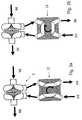
- Fig. 1shows the basic structure of a turbine / pump combination 1, as shown in the in FIGS. 5 to 11 illustrated circuits is used.
- the turbine / pump combination 1by a turbine 2 with a arranged in a turbine housing 3 turbine impeller 4 and a pump 5 with a arranged in a pump housing 6 pump impeller 7, which rotatably via a shaft 8 are coupled together.
- the turbine housing 3 and the pump housing 6form a unit, wherein on the shaft 8, which extends from the turbine side to the pump side, a shaft seal 9 is provided.
- the turbine 2 and the pump 5are formed symmetrically to each other, but other configurations are possible, in particular turbine and pump can be different in size and have other designs for the wheels.
- FIG. 1Arrows in Fig. 1 indicate the flow directions of the two, the turbine / pump combination 1 flowing through coolant flows.
- the turbine impeller 4rotates and leaves the turbine 2 again through a turbine outlet.
- the pump 5sucks coolant through a pump intake manifold from the low-temperature circuit, this promotes and again through the pump Outlet outlet, whereby the coolant is circulated in the low-temperature circuit.
- the arrangement of the various nozzlesdoes not necessarily have the appearance of Fig. 1 correspond.
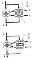
- Fig. 2ashows the turbine / pump combination 1 of Fig. 1 , wherein upstream of the turbine connecting piece serving as a control valve 10 throttle valve 11 is arranged, which controls the turbine 2 flowing through the coolant amount of the refrigerant partial flow from the main coolant circuit and thus also the speed and the associated pump power of the pump 5.
- the throttle valve 11may for example also be arranged behind the turbine outlet nozzle or at another point of the corresponding part of the coolant main circuit.
- a mixing valve 12 serving as a control valve 10is arranged on the turbine connecting piece, wherein it provides a bypass, so that a part of the coolant from the main circuit is mixed with the coolant from the low-temperature circuit.
- the flow rate through the turbine / pump combination 1is successively reduced.
- the mixturemay be used to minimize, for example, in the case of warm-up of the engine, the heat release by the low-temperature radiator to the environment or to the cooling of the medium in the primary heat exchanger, such as the charge air in the charge air / coolant radiator to regulate certain values.
- FIGS. 3a and 3bschematically show the arrangement of a 4-way valve 12, which, as in Fig. 3b shown, a connection between the main circuit and low-temperature circuit allows.
- a variant of a 4-way valve 12is provided with a bypass 13 for reducing the pressure loss in the case of an integrated low-temperature circuit (see. Fig. 4b ).
- Fig. 5shows a main circuit HK, in which the flow direction of the coolant flowing in the main circuit HK is indicated by arrows.
- the main circuit HKhas a main coolant pump, hereinafter referred to as pump P, which circulates the coolant in the main circuit HK.
- pump Pmain coolant pump
- a partial branch THKbranches off from the main circuit HK, the main circuit HK leading the coolant through the motor M in order to cool it, and the partial branch THK to a turbine / pump arranged in the region of the motor M.
- Combination 1leads, wherein the cooling medium flowing in the partial branch THK flows through the turbine / pump combination 1 on the turbine side and drives it as described above.
- the sub-branch THKis then returned to the main circuit HK, that is, after the main circuit HK has passed through the motor M.
- the main circuit HKcarries the hot coolant coming from the engine M to a main radiator HKK through which air flows (indicated by an arrow).
- the air flowis supported by a fan L.
- an engine bypass MBis provided, which is controlled by a thermostat T, which is arranged in front of the pump P (inlet control).
- the engine bypass MBruns parallel to the main radiator HKK. It is also possible to arrange the thermostat after the engine exits or before the coolant inlet (exhaust control).
- charge air LLis supplied to the engine M, the charge air LL passing through a charge air / coolant cooler LLK and being cooled therein.
- the charge air / coolant cooler LLKis part of a low-temperature circuit NK, wherein the flow direction of the coolant flowing therein is indicated by arrows.
- the coolant flowing in this low-temperature circuit NKis circulated by the pump 5 to the turbine / pump combination 1 which, as mentioned above, is driven by the main circuit HK.
- the low-temperature circuit NKleads to a low-temperature radiator NKK, which is arranged parallel to the main radiator HKK and is also cooled by the air flow generated by the fan L.
- the low temperature radiatormay also be located elsewhere, for example adjacent to the main circuit or away from it.
- the function of this very simple arrangement according to the first embodimentis the following:
- the recirculated by the pump P coolant of Main circuit HKflows partly through the motor M to cool it, and partly through the partial branch THK and thus the turbine 2 of the turbine / pump combination 1, whereby the turbine 2 - and thus with the same via the shaft 8 coupled pump 5 of the turbine / pump combination 1 - is driven by the coolant flowing in the main circuit HK.
- the further course of the main circuit HKhas no special features and is essentially made of Fig. 5 so that he needs no further explanation.
- the pump 5 driven by the turbine 2continuously circulates the coolant present therein as a function of the delivery rate of the pump P in the main circuit HK, in which case no special control is provided.
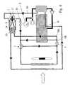
- Fig. 6shows a second embodiment in an operation of the low-temperature circuit as a separate circuit in which a 4-way valve 13 is arranged with a bypass 14 for pressure loss reduction for full load operation in the main and low-temperature circuit HK and NK, which If required, integration of the low-temperature circuit NK in the main circuit HK allows.
- the 4-way valve 13 and the turbine 2 following a controllable throttle valve 11is arranged, which is controlled by a pressure cell D, which flow through in dependence on the charge air pressure p LL coolant (see. Fig. 6 ).
- the further structure of the main circuitsubstantially corresponds to that of the previous embodiment, however, the thermostat T is disposed at the other branch of the engine bypass MB (exhaust control). An intake control is also possible.
- the coolant of the low-temperature circuit NK circulated by the pump 5flows from the pump 5 through the 4-way valve 13, to the low-temperature radiator NKK, to the charge-air / coolant radiator LLK and back to the pump 5.
- the 4-way valve 13is rotated by 90 °, the low-temperature circuit NK is integrated into the main circuit HK.
- the integrationtakes place in particular in operating states in which the charge air cooling is limited must become. Furthermore, it can be used to exchange the coolant of the low-temperature circuit NK and / or to degas the low-temperature circuit NK. How out Fig. 6 can be removed flows in rotated 4-way valve 13 coolant from the branch THK of the main circuit HK in the low-temperature circuit NK, whereas coolant from the low-temperature circuit NK both through the bypass 14 of the 4-way valve 13 and through the pump 5, the 4-way valve 13 and the turbine 2, past the controllable throttle valve 11 flows into the main circuit HK.
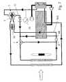
- FIG. 7 illustrated third embodimentcorresponds essentially to the second embodiment of Fig. 6 except that instead of the pressure box D, which controls the throttle valve 11, a temperature controller TR is provided, which controls the throttle valve 11 in dependence on the coolant temperature T KM . Furthermore, no bypass 14 is provided in the 4-way valve 13, so that the entire coolant must flow through the pump 5 and the turbine 2.
- the control of the throttle valvecan also be effected by a control unit which determines and adjusts the coolant flow required in the respective operating state of the engine in the low-temperature circuit.
- Fig. 8shows a fourth embodiment, in which the branch of the partial branch THK in the main circuit HK is arranged only after flowing through the motor M. The return takes place in this case just before the pump P, so that a sufficient pressure gradient is present. Otherwise, the structure substantially corresponds to that of the second embodiment, wherein - according to the third embodiment - no bypass 14 is provided in the 4-way valve 13.
- the coolant for the low-temperature circuit NKis branched off directly after the main radiator HKK, just before the thermostat T and the pump P.
- coolant flowing through the sub-branch THKpasses through the pump 5 of the turbine / pump combination 1, which in this case serves as an additional drive. Subsequently, the coolant flows through the throttle valve 11, which is controlled in dependence on the charge air pressure p LL , and is then fed back to the main circuit HK. If the throttle valve 11 is closed, no coolant passes through the turbine 2 and brakes the pump 5 during "idle", so that less coolant is also conducted through the low-temperature circuit NK.
- the in Fig. 5is similar to the first embodiment shown, is a mixing valve 12, as in Fig. 2b shown provided, which connects the two circuits HK and NK together and is used to control the inflow temperature in the charge air / coolant radiator LLK and thus to temper the charge air.
- the low-temperature radiator NKKcan be bypassed under appropriate operating conditions.
- a check valve RVis provided between them in a part of the main circuit HK in which the pressure is relatively low.
- An in Fig. 11 illustrated seventh embodimentcorresponds substantially to the in Fig. 10 illustrated sixth embodiment, however, the check valve RV, which is provided between the main circuit HK and the low-temperature circuit NK, arranged not after the radiators HKK and NKK but after the engine bypass MB and before the radiators HKK and NKK.
Landscapes
- Engineering & Computer Science (AREA)
- Chemical & Material Sciences (AREA)
- Combustion & Propulsion (AREA)
- Mechanical Engineering (AREA)
- General Engineering & Computer Science (AREA)
- Physics & Mathematics (AREA)
- Thermal Sciences (AREA)
- Supercharger (AREA)
- Supplying Of Containers To The Packaging Station (AREA)
Abstract
Description
Translated fromGermanDie Erfindung betrifft einen Kreislauf zur Kühlung von Ladeluft bei einem Kraftfahrzeug mit einem Turbolader gemäß dem Oberbegriff des Anspruchs 1 sowie ein Verfahren zum Betreiben eines Kreislauf gemäß dem Oberbegriff des Anspruches 12.The invention relates to a circuit for cooling charge air in a motor vehicle with a turbocharger according to the preamble of
Gemäß dem Stand der Technik werden zur Leistungssteigerung von Motoren Turbolader zur Verdichtung der Luft verwendet. Hierbei erfolgt jedoch eine Erwärmung der Luft, im Folgenden als Ladeluft bezeichnet, in Folge der Kompression im Turbolader auf Temperaturen von über 100°C. Um eine derartige Lufterwärmung zu vermindern, werden Luftkühler verwendet, die vorne im Kühlmodul angeordnet sind und zur Kühlung der Ladeluft dienen. Die Ladeluft strömt dabei durch einen Wärmetauscher, der von Umgebungsluft durchströmt und damit gekühlt wird. Dadurch ist eine Abkühlung der Ladeluft auf eine Temperatur möglich, die etwa 15-50 K über der Temperatur der Umgebungsluft liegt.According to the prior art, turbochargers are used to compress the air to increase the performance of engines. In this case, however, there is a heating of the air, hereinafter referred to as charge air, as a result of the compression in the turbocharger to temperatures above 100 ° C. In order to reduce such air heating, air coolers are used, which are arranged in the front of the cooling module and serve to cool the charge air. The charge air flows through a heat exchanger, which is flowed through by ambient air and thus cooled. This makes it possible to cool the charge air to a temperature which is approximately 15-50 K above the ambient air temperature.
Ferner ist bekannt, dass die Kühlung der Ladeluft über einen Kühlmittel-kreislauf erfolgt, beispielsweise einem Niedertemperatur-Kreislauf, in dem das Kühlmittel auf sehr niedrige Temperaturen herabgekühlt wird. Mit diesem kalten Kühlmittel wird die Ladeluft in einem Ladeluft/Kühlmittel-Kühler auf eine vorgegebene Kühltemperatur heruntergekühlt. Für die Verschaltung des Niedertemperatur-Kreislaufs gibt es zwei Varianten, nämlich eine Integration des Niedertemperatur-Kreislaufs in einen Nebenkreislauf des Motorkühlsystems oder eine Ausgestaltung in Form eines separaten Kreislaufs.Furthermore, it is known that the cooling of the charge air takes place via a coolant circuit, for example a low-temperature circuit, in which the coolant is cooled down to very low temperatures. With this cold coolant, the charge air is cooled down to a predetermined cooling temperature in a charge air / coolant cooler. For the interconnection of the Low-temperature circuit there are two variants, namely an integration of the low-temperature circuit in a secondary circuit of the engine cooling system or an embodiment in the form of a separate circuit.
Die Ausgestaltung als separater Kreislauf hat den Vorteil, dass niedrige Temperaturen erreicht werden können. Nachteilig hieran ist, dass er eine eigene, herkömmlicherweise elektrische Kühlmittel-Pumpe benötigt, die zusätzliche Kosten verursacht. Ferner setzt die Lebensdauer des elektrischen Antriebs der Anwendung in Nutzfahrzeugen Grenzen.The design as a separate circuit has the advantage that low temperatures can be achieved. The disadvantage of this is that it requires its own, conventionally electric coolant pump, which causes additional costs. Furthermore, the life of the electric drive limits the application in commercial vehicles.
Beim integrierten Kreislauf kann bei entsprechender Verschaltung auf eine zusätzliche Pumpe verzichtet werden. Allerdings ist man durch den Motor-Thermostaten an die Temperatur des Haupt-Kreislaufs gekoppelt, so dass bei regelnden Thermostaten nicht die gleiche Abkühlung erreicht werden kann, wie bei einem separaten Kreislauf. Außerdem ist bei einer Austrittregelung, d.h. der Thermostat ist am Motoraustritt angeordnet, der Niedertemperatur-Kreislauf pumpendruckseitig anzubringen. Dadurch erhöht sich der Druck im Niedertemperatur-Kühler, was zu Problemen bei der Dauerfestigkeit führen kann.The integrated circuit can be dispensed with an additional pump with appropriate interconnection. However, it is coupled by the motor-thermostat to the temperature of the main circuit, so that with regulating thermostats not the same cooling can be achieved, as in a separate circuit. In addition, with exit control, i. the thermostat is located at the engine outlet, the low-temperature circuit pump pressure side to install. This increases the pressure in the low-temperature cooler, which can lead to problems in fatigue strength.
Aus der
Aus der
Aus der
Aus der
Aus der
Es ist Aufgabe der Erfindung, einen Kreislauf der eingangs genannten Art zu verbessern, insbesondere sollen die Vorteile beider Kreisläufe gemäß dem Stand der Technik miteinander verbunden werden.It is an object of the invention to improve a circuit of the type mentioned, in particular, the advantages of both circuits according to the prior art are to be connected to each other.
Diese Aufgabe wird gelöst durch einen Kreislauf mit den Merkmalen des Anspruchs 1.This object is achieved by a circuit having the features of
Erfindungsgemäß wird eine Kühlmittelgetriebene Kühlmittel-Pumpe vorgesehen, welche den Kreislauf zur Kühlung von Ladeluft eines Kraftfahrzeugs mit einem Turbolader umwälzt. Dabei wird in einem zweiten Kreislauf, insbesondere ein Haupt-Kreislauf mit einer entsprechend ausgelegten Pumpe (Hauptkühlmittel-Pumpe), der mit dem Kreislauf, vorliegend einem Niedertemperatur-Kreislauf, der von der Kühlmittelgetriebenen Pumpe angetrieben wird verbunden sein kann, so dass Kühlmittel von einem in den anderen Kreislauf strömen kann, eine Turbine durch das Kühlmittel des zweiten Kreislaufs angetrieben. Hierbei bilden die Pumpe und die Turbine eine Turbinen/Pumpen-Kombination. Der Hauptkühlmittelkreislauf weist einen Haupt-kühler auf. Erfindungsgemäß ist die Pumpe drehfest mit der Turbine verbunden. Die Pumpe und die Turbine der Turbinen/Pumpen-Kombination sind über eine gemeinsame Welle miteinander starr verbunden.According to the invention, a coolant-driven coolant pump is provided, which circulates the circuit for cooling charge air of a motor vehicle with a turbocharger. It is in a second circuit, in particular a main circuit with a suitably designed pump (main coolant pump), which can be connected to the circuit, in this case a low-temperature circuit, which is driven by the coolant driven pump, so that coolant from a can flow into the other circuit, a turbine through the coolant of the second Driven cycle. Here, the pump and the turbine form a turbine / pump combination. The main coolant circuit has a main radiator. According to the invention, the pump is rotatably connected to the turbine. The pump and the turbine of the turbine / pump combination are rigidly connected to each other via a common shaft.
Erfindungsgemäß sind der Kreislauf, in dem die antreibende Turbine, und der Kreislauf, in dem die von der Turbine angetriebene Pumpe angeordnet ist, zumindest zeitweilig miteinander verbindbar.According to the invention, the circuit in which the driving turbine, and the circuit in which the pump driven by the turbine is arranged, are at least temporarily connectable to each other.
Der zum Antrieb der Turbinen/Pumpen-Kombination erforderliche Kühlmittel-Teilstrom kann beispielsweise auf der Pumpendruckseite eines Haupt-Kreislaufs abgezweigt und am Motoraustritt wieder zurückgeführt werden. Alternativ kann der Kühlmittel-Teilstrom auch am Motoraustritt abgezweigt und auf der Pumpensaugseite wieder zurückgeführt werden. Andere Abzweig- und Rückführstellen sind möglich, zum Beispiel die Entnahme aus Kühlmittel-Anschlüssen am Motorblock, aus dem Heiz-Kreislauf oder aus Entlüftungsleitungen. Die Rückführung kann an beliebigen Stellen des Kühlmittel-Haupt-Kreislaufs erfolgen, an denen das Druckniveau niedrig genug ist, um ein ausreichend großes Druckgefälle zwischen der Entnahmestelle und der Rückführstelle zur Verfügung zu stellen.The required for driving the turbine / pump combination coolant partial flow can be diverted, for example, on the pump pressure side of a main circuit and returned to the engine outlet again. Alternatively, the coolant partial flow can also be branched off at the engine outlet and returned to the pump suction side. Other branch and return points are possible, for example removal from coolant connections on the engine block, from the heating circuit or from vent lines. The recirculation can take place at any point in the coolant main circuit, where the pressure level is low enough to provide a sufficiently large pressure gradient between the sampling point and the return point available.
Bevorzugt sind sämtliche Teile Kunststoff-Spritzgussteile, wobei insbesondere das Pumpen-Laufrad und das Turbinen-Laufrad über eine Welle mittelnander verbunden und einstückig ausgebildet sind.All parts are preferably plastic injection-molded parts, wherein in particular the pump impeller and the turbine impeller are connected to one another via a shaft and formed in one piece.
Da auf beiden Seiten der Turbinen/Pumpen-Kombination sich in der Regel das gleiche Kühlmittel befindet, sind die Anforderungen an Dichtheit zwischeneinander nicht so groß und die Aufwendungen für die Abdichtung daher nur gering.Since both sides of the turbine / pump combination is usually the same coolant, the requirements for tightness between each other are not so large and the cost of the seal therefore only small.
Bevorzugt ist im Kreislauf der Turbine ein Regelventil zur Steuerung der die Turbine durchströmenden Kühlmittelmenge angeordnet. Das Regelventil wird insbesondere durch ein Drosselventil gebildet, das sowohl vor als auch nach der Turbine angeordnet sein kann. Es kann zum Beispiel durch ein elektrisches Stellelement, ein Dehnstoffelement oder eine Druckdose gebildet werden.Preferably, a control valve for controlling the amount of coolant flowing through the turbine is arranged in the circuit of the turbine. The control valve is formed in particular by a throttle valve, which can be arranged both before and after the turbine. It can be formed, for example, by an electric actuator, an expansion element or a pressure cell.
Die Ansteuerung des Regelventils kann zum Beispiel in Abhängigkeit vom Ladedruck erfolgen, das heißt dass bei maximalem Ladedruck die maximale wird insbesondere durch ein Drosselventil gebildet, das sowohl vor als auch nach der Turbine angeordnet sein kann. Es kann zum Beispiel durch ein elektrisches Stellelement, ein Dehnstoffelement oder eine Druckdose gebildet werden.The control of the control valve can be carried out, for example, as a function of the boost pressure, that is, at maximum boost pressure, the maximum is formed in particular by a throttle valve, which can be arranged both before and after the turbine. It can be formed, for example, by an electric actuator, an expansion element or a pressure cell.
Die Ansteuerung des Regelventils kann zum Beispiel in Abhängigkeit vom Ladedruck erfolgen, das heißt dass bei maximalem Ladedruck die maximale Öffnung und somit der maximale Durchfluss vorgesehen ist. Dies kann beispielsweise direkt durch eine von der Ladeluft-Leitung beaufschlagte Druckdose erfolgen. Somit ist der Durchfluss im Niedertemperatur-Kreislauf über die Motordrehzahl, die proportional zur Hauptwasserpumpe ist, und der Ladedruck direkt von der im Ladeluftkühler abzuführenden Wärmemenge abhängig, was nahe dem thermodynamischen Optimum ist.The control of the control valve can for example be carried out in dependence on the boost pressure, that is, the maximum opening and thus the maximum flow is provided at maximum boost pressure. This can for example be done directly by an acted upon by the charge air line pressure cell. Thus, the flow in the low-temperature circuit via the engine speed, which is proportional to the main water pump, and the boost pressure directly from the amount of heat to be dissipated in the intercooler, which is close to the thermodynamic optimum.
Das Regelventil kann auch in Abhängigkeit von der Temperatur angesteuert werden, zum Beispiel der Temperatur des aus dem Ladeluft/Kühlmittel-Kühler austretenden Kühlmittels. Auf diese Weise kann die Ladeluft-Austrittstemperatur weitgehend konstant gehalten werden. Außerdem ist eine wirksame Verhinderung einer lokalen Kühlmittel-Überhitzung gewährleistet. Die temperaturgeführte Steuerung kann beispielsweise über einen Dehnstoffthermostaten erfolgen. Eine weitere Möglichkeit ist die Ansteuerung des Regelventils durch ein Steuergerät, das mehrere Messgrößen verarbeitet.The control valve can also be controlled as a function of the temperature, for example the temperature of the coolant emerging from the charge air / coolant cooler. In this way, the charge air outlet temperature can be kept substantially constant. In addition, effective prevention of local coolant overheating is ensured. The temperature-controlled control can be done for example via a Dehnstoffthermostaten. Another possibility is the control of the control valve by a control unit that processes several variables.
Die zeitweilige Verbindbarkeit des Kreislaufs, in dem die antreibende Turbine, und der Kreislauf, in dem die von der Turbine angetriebene Pumpe kann bevorzugt durch ein Vierwege-Bypass-Ventil oder ein Mischventil erfolgen. Durch eine entsprechende Ausgestaltung können die Vorteile beider Systeme miteinander verbunden werden. Dadurch kann insbesondere erreicht werden, dass in Betriebszuständen, in denen die Ladeluftabkühlung begrenzt werden muss und/oder zur Entgasung des Niedertemperatur-Kreislaufs derselbe integriert wird. In Betriebszuständen, in denen die maximale Ladeluftabkühlung gefordert wird, wird der Niedertemperatur-Kreislauf abgetrennt und über die hydraulisch angetriebene Pumpe angetrieben.The temporary connectivity of the circuit, in which the driving turbine, and the circuit, in The pump driven by the turbine may preferably be made by a four-way bypass valve or a mixing valve. By appropriate design, the advantages of both systems can be interconnected. This can in particular be achieved that in operating states in which the charge air cooling must be limited and / or for degassing of the low-temperature circuit, the same is integrated. In operating conditions in which the maximum charge air cooling is required, the low-temperature circuit is separated and driven by the hydraulically driven pump.
Bevorzugt weist das Vierwege-Bypass-Ventil einen Bypass auf. Der Bypass verringert den Strömungswiderstand, da der Strömungsweg bei Bedarf verkürzt werden kann.Preferably, the four-way bypass valve on a bypass. The bypass reduces the flow resistance, since the flow path can be shortened if necessary.
Vorzugsweise ist das Vierwege-Bypass-Ventil direkt integriert in der Turbinen/Pumpen-Kombination ausgebildet, wodurch sich die Montage vereinfacht.Preferably, the four-way bypass valve is formed directly integrated in the turbine / pump combination, whereby the assembly is simplified.
Zum Druckausgleich sind vorzugsweise die beiden Kreisläufe über ein Rückschlagventil miteinander verbunden.To equalize pressure, the two circuits are preferably connected to one another via a check valve.
Im Folgenden wird die Erfindung anhand einiger Ausführungsbeispiele unter Bezugnahme auf die Zeichnung im Einzelnen erläutert. In der Zeichnung zeigen:
- Fig. 1
- eine Darstellung einer Turbinen/Pumpen-Kombination,
- Fig. 2a, 2b
- verschiedene Anschlussmöglichkeiten der Turbinen/Pumpen-Kombination von
Fig. 1 , - Fig. 3a, 3b
- verschiedene Schaltungen der Turbinen/Pumpen-Kombination in Verbindung mit einem 4-Wege-Ventil,
- Fig. 4a, 4b
- verschiedene Schaltungen der Turbinen/Pumpen-Kombination in Verbindung mit einem alternativen 4-Wege-Ventil,
- Fig. 5
- einen Haupt-Kühlmittel-Kreislauf und einen Niedertemperatur-Kühlmittel-Kreislauf gemäß einem ersten Ausführungsbeispiel,
- Fig. 6
- einen Haupt-Kühlmittel-Kreislauf und einen Niedertemperatur-Kühlmittel-Kreislauf gemäß einem zweiten Ausführungsbeispiel,
- Fig. 7
- einen Haupt-Kühlmittel-Kreislauf und einen Niedertemperatur-Kühlmittel-Kreislauf gemäß einem dritten Ausführungsbeispiel,
- Fig. 8
- einen Haupt-Kühlmittel-Kreislauf und einen Niedertemperatur-Kühlmittel-Kreislauf gemäß einem vierten Ausführungsbeispiel,
- Fig. 9
- einen Haupt-Kühlmittel-Kreislauf und einen Niedertemperatur-Kühlmittel-Kreislauf gemäß einem fünften Ausführungsbeispiel,
- Fig. 10
- einen Haupt-Kühlmittel-Kreislauf und einen Niedertemperatur-Kühlmittel-Kreislauf gemäß einem sechsten Ausführungsbeispiel, und
- Fig. 11
- einen Haupt-Kühlmittel-Kreislauf und einen Niedertemperatur-Kühlmittel-Kreislauf gemäß einem siebten Ausführungsbeispiel.
- Fig. 1
- a representation of a turbine / pump combination,
- Fig. 2a, 2b
- different connection possibilities of the turbines / pump combination of
Fig. 1 . - Fig. 3a, 3b
- various circuits of the turbine / pump combination in conjunction with a 4-way valve,
- Fig. 4a, 4b
- various circuits of the turbine / pump combination in conjunction with an alternative 4-way valve,
- Fig. 5
- a main coolant circuit and a low-temperature coolant circuit according to a first embodiment,
- Fig. 6
- a main coolant circuit and a low-temperature coolant circuit according to a second embodiment,
- Fig. 7
- a main coolant circuit and a low-temperature coolant circuit according to a third embodiment,
- Fig. 8
- a main coolant circuit and a low-temperature coolant circuit according to a fourth embodiment,
- Fig. 9
- a main coolant circuit and a low-temperature coolant circuit according to a fifth embodiment,
- Fig. 10
- a main coolant circuit and a low-temperature coolant circuit according to a sixth embodiment, and
- Fig. 11
- a main refrigerant circuit and a low-temperature refrigerant circuit according to a seventh embodiment.
In
Pfeile in
In
Die
Im Folgenden werden verschiedene Kreisläufe mit einer Turbinen/Pumpenkombination 1, wie zuvor beschrieben, unter Bezugnahme auf die
Der Haupt-Kreislauf HK führt das vom Motor M kommende, heiße Kühlmittel zu einem von Luft (durch einen Pfeil angedeutet) durchströmten Haupt-Kühler HKK. Die Luftströmung wird durch einen Lüfter L unterstützt. Im Haupt-Kreislauf HK ist ferner ein Motorbypass MB vorgesehen, welcher durch einen Thermostaten T geregelt wird, der vor der Pumpe P angeordnet ist (Einlassregelung). Der Motorbypass MB verläuft parallel zum Haupt-Kühler HKK. Es ist auch möglich, den Thermostaten nach dem Motoraustritt oder vor dem Kühlmitteleintritt anzuordnen (Auslassregelung).The main circuit HK carries the hot coolant coming from the engine M to a main radiator HKK through which air flows (indicated by an arrow). The air flow is supported by a fan L. In the main circuit HK also an engine bypass MB is provided, which is controlled by a thermostat T, which is arranged in front of the pump P (inlet control). The engine bypass MB runs parallel to the main radiator HKK. It is also possible to arrange the thermostat after the engine exits or before the coolant inlet (exhaust control).
Von einem Verdichter V kommend wird Ladeluft LL dem Motor M zugeführt, wobei die Ladeluft LL einen Ladeluft/Kühlmittel-Kühler LLK passiert und hierin abgekühlt wird. Der Ladeluft/Kühlmittel-Kühler LLK ist Teil eines Niedertemperatur-Kreislaufs NK, wobei die Strömungsrichtung des hierin strömenden Kühlmittels durch Pfeile angedeutet ist. Das in diesem Niedertemperatur-Kreislauf NK strömende Kühlmittel wird durch die Pumpe 5 der Turbinen/Pumpen-Kombination 1 umgewälzt, welche, wie zuvor erwähnt durch den Haupt-Kreislauf HK angetrieben wird. Der Niedertemperatur-Kreislauf NK führt zu einem Niedertemperatur-Kühler NKK, der parallel zum Haupt-Kühler HKK angeordnet ist und ebenfalls von der durch den Lüfter L erzeugten Luftströmung gekühlt wird. Der Niedertemperatur-Kühler kann auch anderenorts angeordnet sein, zum Beispiel neben dem Haupt-Kreislauf oder entfernt hiervon.Coming from a compressor V, charge air LL is supplied to the engine M, the charge air LL passing through a charge air / coolant cooler LLK and being cooled therein. The charge air / coolant cooler LLK is part of a low-temperature circuit NK, wherein the flow direction of the coolant flowing therein is indicated by arrows. The coolant flowing in this low-temperature circuit NK is circulated by the
Die Funktion dieser sehr einfachen Anordnung gemäß dem ersten Ausführungsbeispiel ist Folgende: Das von der Pumpe P umgewälzte Kühlmittel des Haupt-Kreislaufs HK strömt teilweise durch den Motor M, um diesen zu kühlen, und teilweise durch den Teilzweig THK und somit die Turbine 2 der Turbinen/Pumpen-Kombination 1, wodurch die Turbine 2 - und somit auch die mit derselben über die Welle 8 gekoppelte Pumpe 5 der Turbinen/Pumpen-Kombination 1 - vom im Haupt-Kreislauf HK strömenden Kühlmittel angetrieben wird. Der weitere Verlauf des Haupt-Kreislaufs HK weist keine Besonderheiten auf und ist im Wesentlichen aus
Das von der Pumpe 5 umgewälzte Kühlmittel des Niedertemperatur-Kreislaufs NK strömt von der Pumpe 5 durch das 4-Wege-Ventil 13, zum Niedertemperatur-Kühler NKK, zum Ladeluft/Kühlmittel-Kühler LLK und wieder zur Pumpe 5.The coolant of the low-temperature circuit NK circulated by the
Wird das 4-Wege-Ventil 13 um 90° gedreht, so ist der Niedertemperatur-Kreislauf NK in den Haupt-Kreislauf HK integriert. Die Integration erfolgt insbesondere in Betriebszuständen, in denen die Ladeluftabkühlung begrenzt werden muss. Ferner kann sie dazu verwendet werden, das Kühlmittel des Niedertemperatur-Kreislaufs NK auszutauschen und/oder den Niedertemperatur-Kreislauf NK zu entgasen. Wie aus
Ein in
Die Ansteuerung des Drosselventils kann auch durch ein Steuergerät erfolgen, das den im jeweiligen Betriebszustand des Motors erforderlichen Kühlmittelstrom im Niedertemperatur-Kreislauf ermittelt und einstellt.The control of the throttle valve can also be effected by a control unit which determines and adjusts the coolant flow required in the respective operating state of the engine in the low-temperature circuit.
Bei einem in
Vom Haupt-Kreislauf HK gelangt Kühlmittel, das durch den Teilzweig THK strömt, durch die Pumpe 5 des Turbinen/Pumpen-Kombination 1, welche in diesem Fall als zusätzlicher Antrieb dient. Anschließend strömt das Kühlmittel durch das Drosselventil 11, welches in Abhängigkeit vom Ladeluftdruck pLL gesteuert wird, und wird anschließend wieder dem Haupt-Kreislauf HK zugeführt. Wird das Drosselventil 11 geschlossen, so gelangt kein Kühlmittel durch die Turbine 2 und bremst im "Leerlauf" die Pumpe 5, so dass auch weniger Kühlmittel durch den Niedertemperatur-Kreislauf NK geleitet wird.From the main circuit HK, coolant flowing through the sub-branch THK passes through the
Gemäß einem in
Ein in
- 11
- Turbinen/Pumpen-KombinationTurbine / pump combination
- 22
- Turbineturbine
- 33
- Turbinen-GehäuseTurbine housing
- 44
- Turbinen-LaufradA turbine rotor
- 55
- Pumpepump
- 66
- Pumpen-GehäusePump housing
- 77
- Pumpen-LaufradImpeller
- 88th
- Wellewave
- 99
- Wellendichtungshaft seal
- 1010
- Regelventilcontrol valve
- 1111
- Drosselventilthrottle valve
- 1212
- Mischventilmixing valve
- 1313
- 4-Wege-Ventil4-way valve
- 1414
- Bypassbypass
- DD
- DruckdoseVacuum unit
- HKHK
- Haupt-Kreislauf HKMain circuit HK
- HKKHKK
- Haupt-KühlerMain cooler
- LL
- LüfterFan
- LLLL
- Ladeluftcharge air
- LLKLLK
- Ladeluft/Kühlmittel-KühlerCharge air / coolant cooler
- MM
- Motorengine
- MBMB
- Motorbypassmotor bypass
- NKNK
- Niedertemperatur-KreislaufLow temperature circuit
- NKKNKK
- Niedertemperatur-KühlerLow-temperature cooler
- PP
- Pumpepump
- pLLpLL
- LadeluftdruckBoost Pressure
- RVRV
- Rückschlagventilcheck valve
- TT
- Thermostatthermostat
- THKTHK
- Teilzweigsubbranch
- TKMTKM
- KühlmitteltemperaturCoolant temperature
- TRTR
- Temperaturreglerthermostat
- VV
- Verdichtercompressor
Claims (13)
- Circuit for cooling charge air (LL) in a motor vehicle with a turbocharger, with a low-temperature circuit having a low-temperature cooler (NK), comprising a turbine/pump combination (1) in which a pump (5) is coupled rotationally fixed to a turbine (2), whereby the turbine (2) can be driven by a coolant of a main coolant circuit (HK) and the pump (5) produces circulation in the low-temperature circuit, such that the main coolant circuit (HK), in which the driving turbine (2), and the low-temperature circuit, in which the pump (5) driven by the turbine (2) are arranged, can be connected to one another,characterised in that the main coolant circuit (HK) comprises a main cooler (HKK).
- Circuit according to Claim 1,characterised in that the turbine (2) is integrated in the main coolant circuit (THK), which is designed to be separate at least part of the time.
- Circuit according to either of the preceding claims,characterised in that the pump (5) and the turbine (2) have a common shaft (8).
- Circuit according to any of the preceding claims,characterised in that the pump rotor (7) and/or the turbine rotor (4) and/or the pump housing (6) and/or the turbine housing (3) is a plastic injection moulding.
- Circuit according to any of the preceding claims,characterised in that a regulating valve (10) for controlling the coolant quantity flowing through the turbine (2) is arranged in the circuit of the turbine (2).
- Circuit according to Claim 1,characterised in that a four-way bypass valve (13) or a mixing valve (12) is provided, which allows a change between two separate circuits and a common circuit.
- Circuit according to Claim 6,characterised in that the four-way bypass valve (13) has a bypass (14).
- Circuit according to Claims 6 or 7,characterised in that the four-way bypass valve (13) is designed to be integrated in the turbine/pump combination (1).
- Circuit according to any of the preceding claims,characterised in that the two circuits (HK and NK) are connected to one another via a non-return valve (RV).
- Method for cooling charge air by means of a circuit according to any of the preceding claims, in which circulation is produced by a pump (5),characterised in that the pump (5) is driven directly or indirectly by a turbine (2), the pump (5) and the turbine (2) forming a turbine/pump combination (1).
- Method according to Claim 10,characterised in that the turbine (2) is driven by the main coolant circuit.
- Method according to Claims 10 or 11,characterised in that the turbine/pump combination (1) is controlled by a regulating valve (10) located in the circuit of the turbine (2).
- Method according to Claim 12,characterised in that the regulating valve (10) is controlled as a function of the coolant temperature (TK) and/or of the charge-air pressure (pLL) and/or via a signal from a control unit which determines the engine load and from this determines the coolant requirement in the low-temperature circuit.
Applications Claiming Priority (2)
| Application Number | Priority Date | Filing Date | Title |
|---|---|---|---|
| DE10319762ADE10319762A1 (en) | 2003-04-30 | 2003-04-30 | Charge air cooling circuit and method of operating such a circuit |
| PCT/EP2004/004511WO2004097194A2 (en) | 2003-04-30 | 2004-04-29 | Circuit for cooling charge air, and method for operating such a circuit |
Publications (2)
| Publication Number | Publication Date |
|---|---|
| EP1623101A2 EP1623101A2 (en) | 2006-02-08 |
| EP1623101B1true EP1623101B1 (en) | 2009-01-07 |
Family
ID=33394071
Family Applications (1)
| Application Number | Title | Priority Date | Filing Date |
|---|---|---|---|
| EP04739113AExpired - LifetimeEP1623101B1 (en) | 2003-04-30 | 2004-04-29 | Circuit for cooling charge air, and method for operating such a circuit |
Country Status (5)
| Country | Link |
|---|---|
| US (1) | US7669416B2 (en) |
| EP (1) | EP1623101B1 (en) |
| AT (1) | ATE420278T1 (en) |
| DE (2) | DE10319762A1 (en) |
| WO (1) | WO2004097194A2 (en) |
Cited By (2)
| Publication number | Priority date | Publication date | Assignee | Title |
|---|---|---|---|---|
| DE102009028126A1 (en) | 2009-07-30 | 2011-02-17 | Ford Global Technologies, LLC, Dearborn | Thermal dethrottling of an internal combustion engine |
| DE102010042104A1 (en)* | 2010-10-07 | 2012-04-26 | Bayerische Motoren Werke Aktiengesellschaft | Supercharger for combustion engine, has compressor housing comprising coolant channel that is integrated into coolant circuit and extended tangentially and radially around compressor screw arranged radially around compressor wheel |
Families Citing this family (18)
| Publication number | Priority date | Publication date | Assignee | Title |
|---|---|---|---|---|
| SE527479C2 (en)* | 2004-05-28 | 2006-03-21 | Scania Cv Ab | Arrangements for the recirculation of exhaust gases of a supercharged internal combustion engine |
| SE527481C2 (en)* | 2004-05-28 | 2006-03-21 | Scania Cv Ab | Arrangements for the recirculation of exhaust gases of a supercharged internal combustion engine |
| DE102006054223A1 (en)* | 2006-11-15 | 2008-05-21 | Behr Gmbh & Co. Kg | Cooling system for a motor vehicle |
| DE102007005391A1 (en)* | 2007-02-03 | 2008-08-07 | Behr Gmbh & Co. Kg | Radiator arrangement for a drive train of a motor vehicle |
| SE532245C2 (en)* | 2008-04-18 | 2009-11-24 | Scania Cv Ab | Cooling arrangement of a supercharged internal combustion engine |
| FI124096B (en)* | 2009-12-17 | 2014-03-14 | Wärtsilä Finland Oy | Method of operating a piston engine |
| EP2357335A3 (en) | 2010-01-15 | 2014-01-01 | Bayerische Motoren Werke Aktiengesellschaft | Method and device for cooling charge air |
| DE102010004695A1 (en) | 2010-01-15 | 2011-07-21 | Bayerische Motoren Werke Aktiengesellschaft, 80809 | Device for cooling charge air at intake section of diesel engine of motor vehicle, has control for temperature-independent switching between two operating modes, and cooling circuits coupled together in modes in different way |
| EP2392794B1 (en)* | 2010-06-07 | 2019-02-27 | Ford Global Technologies, LLC | Separately cooled turbo charger for maintaining a no-flow strategy of a cylinder block coolant lining |
| FI20105953L (en)* | 2010-09-17 | 2012-03-18 | Waertsilae Finland Oy | COMBUSTION ENGINE COOLING SYSTEM |
| US8689555B2 (en)* | 2011-04-14 | 2014-04-08 | GM Global Technology Operations LLC | System and method for cooling a turbocharger |
| FR2979288B1 (en)* | 2011-08-25 | 2013-08-23 | Valeo Systemes Thermiques | DEVICE FOR MONITORING A FLOW OF REFRIGERANT FLUID AND CIRCUIT INCORPORATING SUCH A DEVICE |
| ES2529213T3 (en)* | 2011-12-19 | 2015-02-18 | Fpt Industrial S.P.A. | Device for the circulation of water in a cooling circuit of an internal combustion engine |
| GB2501304B (en) | 2012-04-19 | 2019-01-16 | Ford Global Tech Llc | Apparatus and method for engine warm up |
| DE102013211700B3 (en)* | 2013-06-20 | 2014-09-25 | Ford Global Technologies, Llc | A vehicle heating system and method of heating the interior of a vehicle with a vehicle heating system |
| KR101664731B1 (en)* | 2015-07-30 | 2016-10-12 | 현대자동차주식회사 | Sub cooling system |
| EP3385524B1 (en)* | 2017-04-03 | 2019-07-17 | Denso Corporation | System for controlling an intake temperature of charge air |
| DE102023115867A1 (en) | 2023-06-16 | 2024-12-19 | Schaeffler Technologies AG & Co. KG | Turbine pump of a vehicle cooling system and such a vehicle cooling system |
Citations (1)
| Publication number | Priority date | Publication date | Assignee | Title |
|---|---|---|---|---|
| DE19854544A1 (en)* | 1998-11-26 | 2000-06-08 | Mtu Friedrichshafen Gmbh | Cooling system for charged internal combustion engine has heat exchanger for cooling electronic components in auxiliary branch of low temp. circuit |
Family Cites Families (24)
| Publication number | Priority date | Publication date | Assignee | Title |
|---|---|---|---|---|
| US2568254A (en)* | 1946-11-25 | 1951-09-18 | Hpm Dev Corp | Fluid pressure-operated actuator for hydraulic valves |
| US3229456A (en)* | 1960-12-19 | 1966-01-18 | Gratzmuller Jean Louis | Cooling systems for internal combustion engines |
| US3141293A (en)* | 1961-08-22 | 1964-07-21 | Cooper Bessemer Corp | Method and apparatus for refrigerating combustion air for internal combustion engines |
| US3134371A (en)* | 1962-10-29 | 1964-05-26 | Cooper Bessemer Corp | Cooling system for internal combustion engines |
| FR1597204A (en)* | 1968-12-27 | 1970-06-22 | ||
| US3752132A (en)* | 1971-04-19 | 1973-08-14 | Caterpillar Tractor Co | Dual cooling system for engines |
| US3829238A (en)* | 1972-08-10 | 1974-08-13 | W Speck | Centrifugal pumps composed primarily of plastic components |
| DE2245257B2 (en)* | 1972-09-15 | 1974-06-27 | Motoren- Und Turbinen-Union Friedrichshafen Gmbh, 7990 Friedrichshafen | Cooling device for a supercharged internal combustion engine |
| US4237689A (en)* | 1978-05-26 | 1980-12-09 | Sampietro Achilles C | Internal combustion engines |
| DE3320827A1 (en) | 1983-06-09 | 1984-12-20 | Heinz 2058 Lauenburg Bollhorn | Internal combustion engine with supercharging |
| US5269143A (en) | 1992-12-07 | 1993-12-14 | Ford Motor Company | Diesel engine turbo-expander |
| US5353597A (en)* | 1992-12-16 | 1994-10-11 | Northern Research & Engineering Corporation | Inlet air cooling system |
| US5427508A (en)* | 1993-06-07 | 1995-06-27 | Kapich; Davorin | Electro-pneumatic blower |
| US5415147A (en)* | 1993-12-23 | 1995-05-16 | General Electric Company | Split temperature regulating system and method for turbo charged internal combustion engine |
| JPH08158871A (en)* | 1994-12-02 | 1996-06-18 | Toyota Motor Corp | Internal combustion engine cooling system |
| DE19834135A1 (en) | 1998-07-29 | 2000-02-03 | Daimler Chrysler Ag | Charger turbine drive in an internal combustion motor also drives the coolant pump for a simplified coolant drive system at a lower cost |
| US6345961B1 (en)* | 1999-01-26 | 2002-02-12 | Fluid Equipment Development Company | Hydraulic energy recovery device |
| US6098576A (en)* | 1999-02-12 | 2000-08-08 | General Electric Company | Enhanced split cooling system |
| DE19961825A1 (en) | 1999-12-21 | 2001-06-28 | Valeo Klimasysteme Gmbh | Cooling-heating circuit with two coolers |
| FR2811376B1 (en) | 2000-07-06 | 2003-02-07 | Peugeot Citroen Automobiles Sa | DEVICE FOR THERMAL REGULATION OF THE INTAKE AIR OF A MOTOR VEHICLE INTERNAL COMBUSTION ENGINE |
| US6647934B2 (en)* | 2001-10-01 | 2003-11-18 | General Electric Company | Unified rotary flow control valve for internal combustion engine cooling system |
| FR2830577B1 (en)* | 2001-10-10 | 2004-03-05 | Taema | TWO-STAGE COMPRESSOR IN PARTICULAR FOR A BREATHING APPARATUS |
| DE10215262B4 (en)* | 2002-04-06 | 2014-12-31 | Daimler Ag | Cooling system, in particular for a motor vehicle engine with indirect intercooling |
| DE10251463A1 (en)* | 2002-11-05 | 2004-05-19 | BSH Bosch und Siemens Hausgeräte GmbH | Electrically-driven water circulation pump for automobile engine, ship, laundry machine or dish washing machine, with circulated liquid providing cooling of rotor of drive motor |
- 2003
- 2003-04-30DEDE10319762Apatent/DE10319762A1/ennot_activeWithdrawn
- 2004
- 2004-04-29DEDE502004008823Tpatent/DE502004008823D1/ennot_activeExpired - Lifetime
- 2004-04-29ATAT04739113Tpatent/ATE420278T1/ennot_activeIP Right Cessation
- 2004-04-29USUS10/554,870patent/US7669416B2/ennot_activeExpired - Fee Related
- 2004-04-29WOPCT/EP2004/004511patent/WO2004097194A2/enactiveApplication Filing
- 2004-04-29EPEP04739113Apatent/EP1623101B1/ennot_activeExpired - Lifetime
Patent Citations (1)
| Publication number | Priority date | Publication date | Assignee | Title |
|---|---|---|---|---|
| DE19854544A1 (en)* | 1998-11-26 | 2000-06-08 | Mtu Friedrichshafen Gmbh | Cooling system for charged internal combustion engine has heat exchanger for cooling electronic components in auxiliary branch of low temp. circuit |
Cited By (3)
| Publication number | Priority date | Publication date | Assignee | Title |
|---|---|---|---|---|
| DE102009028126A1 (en) | 2009-07-30 | 2011-02-17 | Ford Global Technologies, LLC, Dearborn | Thermal dethrottling of an internal combustion engine |
| DE102009028126B4 (en)* | 2009-07-30 | 2011-09-22 | Ford Global Technologies, Llc | Thermal dethrottling of an internal combustion engine |
| DE102010042104A1 (en)* | 2010-10-07 | 2012-04-26 | Bayerische Motoren Werke Aktiengesellschaft | Supercharger for combustion engine, has compressor housing comprising coolant channel that is integrated into coolant circuit and extended tangentially and radially around compressor screw arranged radially around compressor wheel |
Also Published As
| Publication number | Publication date |
|---|---|
| EP1623101A2 (en) | 2006-02-08 |
| DE502004008823D1 (en) | 2009-02-26 |
| US7669416B2 (en) | 2010-03-02 |
| ATE420278T1 (en) | 2009-01-15 |
| DE10319762A1 (en) | 2004-12-02 |
| WO2004097194A2 (en) | 2004-11-11 |
| US20060225417A1 (en) | 2006-10-12 |
| WO2004097194A3 (en) | 2004-12-02 |
Similar Documents
| Publication | Publication Date | Title |
|---|---|---|
| EP1623101B1 (en) | Circuit for cooling charge air, and method for operating such a circuit | |
| DE102010025733B4 (en) | Heat exchange systems for motor vehicles | |
| DE10215262B4 (en) | Cooling system, in particular for a motor vehicle engine with indirect intercooling | |
| EP1716325B1 (en) | Arrangement for cooling exhaust gas and charge air | |
| EP1905978B1 (en) | Cooling system for a charged combustion engine with a charge-air cooler | |
| EP1616087B1 (en) | Circuit arrangement which cools charging air and method for the operation of said type of circuit arrangement | |
| EP2464839B1 (en) | Device for utilizing waste heat | |
| EP1913243B1 (en) | Cooling system for a vehicle, and method for the operation of a cooling system | |
| DE102013211700B3 (en) | A vehicle heating system and method of heating the interior of a vehicle with a vehicle heating system | |
| EP1923549B1 (en) | Cooling system for a motor vehicle | |
| EP1342893B1 (en) | Apparatus for cooling charge air and method of operating such an apparatus | |
| EP1342892B1 (en) | Circuit for cooling charge air and method to operate such circuit | |
| DE102018214152B3 (en) | Cooling system for an internal combustion engine, in particular cylinder head cooling with intercooler | |
| DE102019206201B3 (en) | Split cooling system for an internal combustion engine with several cooling circuits | |
| DE102013208857B4 (en) | System and method for thermal management of an engine for applications with split cooling and integrated exhaust manifold | |
| EP3530899A1 (en) | Cooling system and combustion engine | |
| DE102011101337A1 (en) | Circuit arrangement for refrigeration of auxiliary unit of internal combustion engine of hybrid vehicle e.g. motor car, has low-temperature circuit linked with high-temperature circuit, so that coolant is passed via high-temperature circuit | |
| EP3530901A1 (en) | Combustion engine and motor vehicle | |
| DE102012011227A1 (en) | Internal combustion engine for passenger car, has first and second liquid-gas heat exchangers arranged downstream of compressor arranged with air intake, where each of liquid-gas heat exchangers comprises bypass device | |
| DE102019105893A1 (en) | Thermal management system and method for a vehicle drive system | |
| DE102020206674A1 (en) | Hybrid vehicle with a cooling system | |
| DE10139315A1 (en) | Cooling system for internal combustion engine, has single coolant pump and individual heat exchangers for engine and engine components | |
| DE102010009290B4 (en) | Coolant circuit for an internal combustion engine with exhaust gas recirculation | |
| DE102017005336B4 (en) | Cooling system for an internal combustion engine and another object | |
| EP3412883A1 (en) | Combustion engine and motor vehicle |
Legal Events
| Date | Code | Title | Description |
|---|---|---|---|
| PUAI | Public reference made under article 153(3) epc to a published international application that has entered the european phase | Free format text:ORIGINAL CODE: 0009012 | |
| 17P | Request for examination filed | Effective date:20051130 | |
| AK | Designated contracting states | Kind code of ref document:A2 Designated state(s):AT BE BG CH CY CZ DE DK EE ES FI FR GB GR HU IE IT LI LU MC NL PL PT RO SE SI SK TR | |
| DAX | Request for extension of the european patent (deleted) | ||
| 17Q | First examination report despatched | Effective date:20060227 | |
| GRAP | Despatch of communication of intention to grant a patent | Free format text:ORIGINAL CODE: EPIDOSNIGR1 | |
| GRAS | Grant fee paid | Free format text:ORIGINAL CODE: EPIDOSNIGR3 | |
| GRAA | (expected) grant | Free format text:ORIGINAL CODE: 0009210 | |
| AK | Designated contracting states | Kind code of ref document:B1 Designated state(s):AT BE BG CH CY CZ DE DK EE ES FI FR GB GR HU IE IT LI LU MC NL PL PT RO SE SI SK TR | |
| REG | Reference to a national code | Ref country code:GB Ref legal event code:FG4D Free format text:NOT ENGLISH | |
| REG | Reference to a national code | Ref country code:CH Ref legal event code:EP | |
| REG | Reference to a national code | Ref country code:IE Ref legal event code:FG4D Free format text:LANGUAGE OF EP DOCUMENT: GERMAN | |
| REF | Corresponds to: | Ref document number:502004008823 Country of ref document:DE Date of ref document:20090226 Kind code of ref document:P | |
| REG | Reference to a national code | Ref country code:SE Ref legal event code:TRGR | |
| PG25 | Lapsed in a contracting state [announced via postgrant information from national office to epo] | Ref country code:SI Free format text:LAPSE BECAUSE OF FAILURE TO SUBMIT A TRANSLATION OF THE DESCRIPTION OR TO PAY THE FEE WITHIN THE PRESCRIBED TIME-LIMIT Effective date:20090107 Ref country code:NL Free format text:LAPSE BECAUSE OF FAILURE TO SUBMIT A TRANSLATION OF THE DESCRIPTION OR TO PAY THE FEE WITHIN THE PRESCRIBED TIME-LIMIT Effective date:20090107 | |
| NLV1 | Nl: lapsed or annulled due to failure to fulfill the requirements of art. 29p and 29m of the patents act | ||
| PG25 | Lapsed in a contracting state [announced via postgrant information from national office to epo] | Ref country code:FI Free format text:LAPSE BECAUSE OF FAILURE TO SUBMIT A TRANSLATION OF THE DESCRIPTION OR TO PAY THE FEE WITHIN THE PRESCRIBED TIME-LIMIT Effective date:20090107 Ref country code:ES Free format text:LAPSE BECAUSE OF FAILURE TO SUBMIT A TRANSLATION OF THE DESCRIPTION OR TO PAY THE FEE WITHIN THE PRESCRIBED TIME-LIMIT Effective date:20090418 | |
| REG | Reference to a national code | Ref country code:IE Ref legal event code:FD4D | |
| PG25 | Lapsed in a contracting state [announced via postgrant information from national office to epo] | Ref country code:PL Free format text:LAPSE BECAUSE OF FAILURE TO SUBMIT A TRANSLATION OF THE DESCRIPTION OR TO PAY THE FEE WITHIN THE PRESCRIBED TIME-LIMIT Effective date:20090107 Ref country code:PT Free format text:LAPSE BECAUSE OF FAILURE TO SUBMIT A TRANSLATION OF THE DESCRIPTION OR TO PAY THE FEE WITHIN THE PRESCRIBED TIME-LIMIT Effective date:20090608 | |
| PG25 | Lapsed in a contracting state [announced via postgrant information from national office to epo] | Ref country code:IE Free format text:LAPSE BECAUSE OF FAILURE TO SUBMIT A TRANSLATION OF THE DESCRIPTION OR TO PAY THE FEE WITHIN THE PRESCRIBED TIME-LIMIT Effective date:20090107 Ref country code:CZ Free format text:LAPSE BECAUSE OF FAILURE TO SUBMIT A TRANSLATION OF THE DESCRIPTION OR TO PAY THE FEE WITHIN THE PRESCRIBED TIME-LIMIT Effective date:20090107 Ref country code:DK Free format text:LAPSE BECAUSE OF FAILURE TO SUBMIT A TRANSLATION OF THE DESCRIPTION OR TO PAY THE FEE WITHIN THE PRESCRIBED TIME-LIMIT Effective date:20090107 Ref country code:EE Free format text:LAPSE BECAUSE OF FAILURE TO SUBMIT A TRANSLATION OF THE DESCRIPTION OR TO PAY THE FEE WITHIN THE PRESCRIBED TIME-LIMIT Effective date:20090107 | |
| BERE | Be: lapsed | Owner name:BEHR G.M.B.H. & CO. KG Effective date:20090430 | |
| PLBE | No opposition filed within time limit | Free format text:ORIGINAL CODE: 0009261 | |
| STAA | Information on the status of an ep patent application or granted ep patent | Free format text:STATUS: NO OPPOSITION FILED WITHIN TIME LIMIT | |
| PG25 | Lapsed in a contracting state [announced via postgrant information from national office to epo] | Ref country code:RO Free format text:LAPSE BECAUSE OF FAILURE TO SUBMIT A TRANSLATION OF THE DESCRIPTION OR TO PAY THE FEE WITHIN THE PRESCRIBED TIME-LIMIT Effective date:20090107 Ref country code:SK Free format text:LAPSE BECAUSE OF FAILURE TO SUBMIT A TRANSLATION OF THE DESCRIPTION OR TO PAY THE FEE WITHIN THE PRESCRIBED TIME-LIMIT Effective date:20090107 | |
| REG | Reference to a national code | Ref country code:CH Ref legal event code:PL | |
| EUG | Se: european patent has lapsed | ||
| 26N | No opposition filed | Effective date:20091008 | |
| GBPC | Gb: european patent ceased through non-payment of renewal fee | Effective date:20090429 | |
| PG25 | Lapsed in a contracting state [announced via postgrant information from national office to epo] | Ref country code:BG Free format text:LAPSE BECAUSE OF FAILURE TO SUBMIT A TRANSLATION OF THE DESCRIPTION OR TO PAY THE FEE WITHIN THE PRESCRIBED TIME-LIMIT Effective date:20090407 Ref country code:CH Free format text:LAPSE BECAUSE OF NON-PAYMENT OF DUE FEES Effective date:20090430 Ref country code:LI Free format text:LAPSE BECAUSE OF NON-PAYMENT OF DUE FEES Effective date:20090430 | |
| PG25 | Lapsed in a contracting state [announced via postgrant information from national office to epo] | Ref country code:MC Free format text:LAPSE BECAUSE OF NON-PAYMENT OF DUE FEES Effective date:20090430 Ref country code:GB Free format text:LAPSE BECAUSE OF NON-PAYMENT OF DUE FEES Effective date:20090429 | |
| PG25 | Lapsed in a contracting state [announced via postgrant information from national office to epo] | Ref country code:BE Free format text:LAPSE BECAUSE OF NON-PAYMENT OF DUE FEES Effective date:20090430 | |
| PGFP | Annual fee paid to national office [announced via postgrant information from national office to epo] | Ref country code:FR Payment date:20100428 Year of fee payment:7 | |
| PG25 | Lapsed in a contracting state [announced via postgrant information from national office to epo] | Ref country code:AT Free format text:LAPSE BECAUSE OF NON-PAYMENT OF DUE FEES Effective date:20090429 | |
| PG25 | Lapsed in a contracting state [announced via postgrant information from national office to epo] | Ref country code:GR Free format text:LAPSE BECAUSE OF FAILURE TO SUBMIT A TRANSLATION OF THE DESCRIPTION OR TO PAY THE FEE WITHIN THE PRESCRIBED TIME-LIMIT Effective date:20090408 | |
| PG25 | Lapsed in a contracting state [announced via postgrant information from national office to epo] | Ref country code:IT Free format text:LAPSE BECAUSE OF FAILURE TO SUBMIT A TRANSLATION OF THE DESCRIPTION OR TO PAY THE FEE WITHIN THE PRESCRIBED TIME-LIMIT Effective date:20090107 | |
| PG25 | Lapsed in a contracting state [announced via postgrant information from national office to epo] | Ref country code:LU Free format text:LAPSE BECAUSE OF NON-PAYMENT OF DUE FEES Effective date:20090429 | |
| PG25 | Lapsed in a contracting state [announced via postgrant information from national office to epo] | Ref country code:SE Free format text:LAPSE BECAUSE OF NON-PAYMENT OF DUE FEES Effective date:20090430 | |
| PG25 | Lapsed in a contracting state [announced via postgrant information from national office to epo] | Ref country code:HU Free format text:LAPSE BECAUSE OF FAILURE TO SUBMIT A TRANSLATION OF THE DESCRIPTION OR TO PAY THE FEE WITHIN THE PRESCRIBED TIME-LIMIT Effective date:20090708 | |
| PG25 | Lapsed in a contracting state [announced via postgrant information from national office to epo] | Ref country code:TR Free format text:LAPSE BECAUSE OF FAILURE TO SUBMIT A TRANSLATION OF THE DESCRIPTION OR TO PAY THE FEE WITHIN THE PRESCRIBED TIME-LIMIT Effective date:20090107 | |
| PG25 | Lapsed in a contracting state [announced via postgrant information from national office to epo] | Ref country code:CY Free format text:LAPSE BECAUSE OF FAILURE TO SUBMIT A TRANSLATION OF THE DESCRIPTION OR TO PAY THE FEE WITHIN THE PRESCRIBED TIME-LIMIT Effective date:20090107 | |
| REG | Reference to a national code | Ref country code:FR Ref legal event code:ST Effective date:20111230 | |
| PG25 | Lapsed in a contracting state [announced via postgrant information from national office to epo] | Ref country code:FR Free format text:LAPSE BECAUSE OF NON-PAYMENT OF DUE FEES Effective date:20110502 | |
| PGFP | Annual fee paid to national office [announced via postgrant information from national office to epo] | Ref country code:DE Payment date:20120516 Year of fee payment:9 | |
| PG25 | Lapsed in a contracting state [announced via postgrant information from national office to epo] | Ref country code:DE Free format text:LAPSE BECAUSE OF NON-PAYMENT OF DUE FEES Effective date:20131101 | |
| REG | Reference to a national code | Ref country code:DE Ref legal event code:R119 Ref document number:502004008823 Country of ref document:DE Effective date:20131101 |