EP1622700B1 - Method for operating a filter - Google Patents
Method for operating a filterDownload PDFInfo
- Publication number
- EP1622700B1 EP1622700B1EP04751962.4AEP04751962AEP1622700B1EP 1622700 B1EP1622700 B1EP 1622700B1EP 04751962 AEP04751962 AEP 04751962AEP 1622700 B1EP1622700 B1EP 1622700B1
- Authority
- EP
- European Patent Office
- Prior art keywords
- filter
- chamber
- fluid
- water
- line
- Prior art date
- Legal status (The legal status is an assumption and is not a legal conclusion. Google has not performed a legal analysis and makes no representation as to the accuracy of the status listed.)
- Expired - Lifetime
Links
- 238000000034methodMethods0.000titleclaimsdescription19
- 239000012530fluidSubstances0.000claimsdescription74
- XLYOFNOQVPJJNP-UHFFFAOYSA-NwaterSubstancesOXLYOFNOQVPJJNP-UHFFFAOYSA-N0.000claimsdescription66
- 239000000645desinfectantSubstances0.000claimsdescription38
- 238000004891communicationMethods0.000claimsdescription17
- 238000004140cleaningMethods0.000claimsdescription10
- 239000012141concentrateSubstances0.000claimsdescription6
- 230000000694effectsEffects0.000claimsdescription3
- 238000001914filtrationMethods0.000description25
- 230000000813microbial effectEffects0.000description15
- 238000005202decontaminationMethods0.000description14
- 230000003588decontaminative effectEffects0.000description14
- 238000005406washingMethods0.000description10
- 238000004659sterilization and disinfectionMethods0.000description4
- 230000001954sterilising effectEffects0.000description3
- 238000004090dissolutionMethods0.000description2
- 238000012061filter integrity testMethods0.000description2
- 239000007788liquidSubstances0.000description2
- 239000000126substanceSubstances0.000description2
- 239000002033PVDF binderSubstances0.000description1
- 239000002253acidSubstances0.000description1
- 230000003213activating effectEffects0.000description1
- 230000001580bacterial effectEffects0.000description1
- 239000003153chemical reaction reagentSubstances0.000description1
- 239000000356contaminantSubstances0.000description1
- 238000009792diffusion processMethods0.000description1
- 238000010438heat treatmentMethods0.000description1
- 239000012535impuritySubstances0.000description1
- 238000011017operating methodMethods0.000description1
- 239000002245particleSubstances0.000description1
- 239000012466permeateSubstances0.000description1
- 229920002981polyvinylidene fluoridePolymers0.000description1
- 239000007921spraySubstances0.000description1
- 230000000007visual effectEffects0.000description1
Images


Classifications
- A—HUMAN NECESSITIES
- A61—MEDICAL OR VETERINARY SCIENCE; HYGIENE
- A61L—METHODS OR APPARATUS FOR STERILISING MATERIALS OR OBJECTS IN GENERAL; DISINFECTION, STERILISATION OR DEODORISATION OF AIR; CHEMICAL ASPECTS OF BANDAGES, DRESSINGS, ABSORBENT PADS OR SURGICAL ARTICLES; MATERIALS FOR BANDAGES, DRESSINGS, ABSORBENT PADS OR SURGICAL ARTICLES
- A61L2/00—Methods or apparatus for disinfecting or sterilising materials or objects other than foodstuffs or contact lenses; Accessories therefor
- A61L2/16—Methods or apparatus for disinfecting or sterilising materials or objects other than foodstuffs or contact lenses; Accessories therefor using chemical substances
- A61L2/18—Liquid substances or solutions comprising solids or dissolved gases
- A—HUMAN NECESSITIES
- A61—MEDICAL OR VETERINARY SCIENCE; HYGIENE
- A61L—METHODS OR APPARATUS FOR STERILISING MATERIALS OR OBJECTS IN GENERAL; DISINFECTION, STERILISATION OR DEODORISATION OF AIR; CHEMICAL ASPECTS OF BANDAGES, DRESSINGS, ABSORBENT PADS OR SURGICAL ARTICLES; MATERIALS FOR BANDAGES, DRESSINGS, ABSORBENT PADS OR SURGICAL ARTICLES
- A61L2/00—Methods or apparatus for disinfecting or sterilising materials or objects other than foodstuffs or contact lenses; Accessories therefor
- A61L2/16—Methods or apparatus for disinfecting or sterilising materials or objects other than foodstuffs or contact lenses; Accessories therefor using chemical substances
- A61L2/22—Phase substances, e.g. smokes, aerosols or sprayed or atomised substances
- B—PERFORMING OPERATIONS; TRANSPORTING
- B01—PHYSICAL OR CHEMICAL PROCESSES OR APPARATUS IN GENERAL
- B01D—SEPARATION
- B01D29/00—Filters with filtering elements stationary during filtration, e.g. pressure or suction filters, not covered by groups B01D24/00 - B01D27/00; Filtering elements therefor
- B01D29/62—Regenerating the filter material in the filter
- B01D29/66—Regenerating the filter material in the filter by flushing, e.g. counter-current air-bumps
- C—CHEMISTRY; METALLURGY
- C02—TREATMENT OF WATER, WASTE WATER, SEWAGE, OR SLUDGE
- C02F—TREATMENT OF WATER, WASTE WATER, SEWAGE, OR SLUDGE
- C02F1/00—Treatment of water, waste water, or sewage
- C02F1/44—Treatment of water, waste water, or sewage by dialysis, osmosis or reverse osmosis
- C02F1/444—Treatment of water, waste water, or sewage by dialysis, osmosis or reverse osmosis by ultrafiltration or microfiltration
- B—PERFORMING OPERATIONS; TRANSPORTING
- B01—PHYSICAL OR CHEMICAL PROCESSES OR APPARATUS IN GENERAL
- B01D—SEPARATION
- B01D2201/00—Details relating to filtering apparatus
- B01D2201/08—Regeneration of the filter
- B01D2201/085—Regeneration of the filter using another chemical than the liquid to be filtered
- B—PERFORMING OPERATIONS; TRANSPORTING
- B01—PHYSICAL OR CHEMICAL PROCESSES OR APPARATUS IN GENERAL
- B01D—SEPARATION
- B01D2201/00—Details relating to filtering apparatus
- B01D2201/08—Regeneration of the filter
- B01D2201/088—Arrangements for killing microorganisms
- C—CHEMISTRY; METALLURGY
- C02—TREATMENT OF WATER, WASTE WATER, SEWAGE, OR SLUDGE
- C02F—TREATMENT OF WATER, WASTE WATER, SEWAGE, OR SLUDGE
- C02F2303/00—Specific treatment goals
- C02F2303/16—Regeneration of sorbents, filters
Definitions
- the present inventionrelates to filtration system for filtering fluids, and more particularly to a filtration system capable of cleaning and decontaminating a filter element.
- filtered wateris used in a fluid microbial decontamination apparatus, for the disinfection or sterilization of medical, pharmaceutical, dental, or mortuary devices, and the like. It is important in this application to minimize the introduction of any impurities into the decontamination apparatus. Accordingly, water is passed through an incoming filter before the water is used in connection with any disinfection or sterilization processes. As the filter is repeatedly used to filter the water, the filter becomes filled with contaminants, thus reducing the effectiveness of the filter. Therefore, it becomes necessary to periodically clean the filter, see e.g. US 3637079 , US 5632890 , US 4177143 .
- the present inventionprovides an improved filtration system capable of cleaning and decontaminating a filter element.
- a method for operating a filterincluding: (a) a first chamber having a first inlet port in communication with a source of a fluid to be filtered; (b) a second chamber having at least one filter port; (c) a filter element disposed between the first chamber and the second chamber; and (d) a first outlet port in communication with a drain, the method comprising the steps of: receiving the fluid into the filter through the first inlet port; passing the fluid in the filter through the filter element, from the first chamber to the second chamber, to provide a filtered fluid; removing the filtered fluid from the second chamber through said at least one filter port; closing the first inlet port; opening the first outlet port to drain the filter; mixing filtered fluid removed from the second chamber (60) with a disinfectant concentrate to form a disinfectant solution; receiving disinfectant solution into the filter through the at least one filter port; and passing the disinfectant solution through the filter element, from the second chamber to the first chamber, to effect cleaning of the filter element; and removing the disinfect
- a method for operating a filterincluding: (a) a first chamber; (b) a second chamber; and (c) a filter element disposed between the first chamber and the second chamber, said method comprising the steps of: (1) passing a fluid through the filter element, from the first chamber to the second chamber; (2) draining fluid from the filter; and (3) backflushing the filter element by passing a disinfectant solution through the filter element, from the second chamber to the first chamber.
- a filtration systemcomprising: (a) a first chamber having a first inlet port in communication with a source of a fluid to be filtered; (b) a second chamber having at least one filter port for receiving a disinfectant solution; (c) a filter element disposed between the first chamber and the second chamber; and (d) a first outlet port in communication with a drain; wherein the fluid is filtered by passing the fluid through the filter element, from the first chamber to the second chamber, and the filter element is cleaned by passing the disinfectant solution through the filter element, from the second chamber to the first chamber.
- a method for operating a filterincluding: (a) a first chamber; (b) a second chamber; and (c) a filter element disposed between the first chamber and the second chamber, said method comprising the steps of: (1) forcing compressed air into the first chamber; (2) pressurizing the first chamber to a predetermined pressure; (3) sensing a pressure decay in the first chamber, as the compressed air passes through the filter element into the second chamber; (4) and determining the integrity of the filter in accordance with the sensed pressure decay.
- An advantage of the present inventionis the provision of a filtration system that effectively cleans and decontaminates the filter by exposing the filter to a decontamination fluid.
- Another advantage of the present inventionis the provision of a method for cleaning and decontaminating a filter by exposing the filter to a decontamination fluid.
- Still another advantage of the present inventionis the provision of a filtration system that monitors the integrity of the filter.
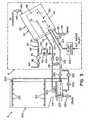
- FIG. 1is a perspective view of a filtration system, including a filter, partially broken to show the interior thereof;
- FIG. 2is a schematic view of the filtration system shown in FIG.1 ;
- FIG. 3is a schematic view of the filtration system shown in FIG. 1 as used in connection with an exemplary fluid microbial system, during a fill mode operation;
- FIG. 4is a schematic view of the filtration system shown in FIG. 1 as used in connection with an exemplary fluid microbial system, during a circulation mode operation;
- FIG. 5is a schematic view of the filtration system shown in FIG. 1 as used in connection with an exemplary fluid microbial system, during a drain mode operation.
- FIGS. 3-5show a filtration system 10, according to a preferred embodiment of the present invention, in connection with an exemplary fluid microbial decontamination system 5.
- Fluid microbial decontamination system 5is generally comprised of a washing chamber 200, a spray system 300, a circulation pump 400, and a chemical disinfectant system (CDS) 500.
- Washing chamber 200includes a sump 210 where fluid collects.
- a heating element 220is provided to heat the fluid collected in sump 210.
- Sprayer system 300includes a plurality of nozzles 310 that dispense fluid into washing chamber 200.
- Circulation pump 400pumps fluid from sump 210 throughout the system, as will be described in further detail below.
- Valves 250, 252 and 254control the flow of fluid along a plurality of fluid paths of fluid microbial decontamination system 5. It should be appreciated that fluid microbial decontamination system 5 may include many additional fluid paths not described herein.
- CDS 500includes a housing (not shown) for holding a cartridge or cup (not shown) containing a disinfectant concentrate or reagents that reacts with a fluid (e.g., filtered water) to form a disinfectant solution.
- a fluide.g., filtered water
- the disinfectant solutionis supplied to washing chamber 200, wherein objects (e.g., medical instruments) are exposed to the disinfectant solution to effect microbial decontamination of the objects.
- the disinfectant solutionis also supplied to filtration system 10 in accordance with the present invention, as will be described in detail below.
- FIG. 2is a detailed schematic view of filtration system 10 including filter 20.
- Filter 20generally comprised of an outer housing 30, a filter element 50, and a base 70.
- Outer housing 30has an outer surface 32 and an inner surface 34.
- Outer housing 30is fixed to base 70, to form a fluid-tight container that defines a cavity 3.6.
- Filter element 50has an outer surface 52 and an inner surface 54. Filter element 50 is located within cavity 36 defined by outer housing 30. Filter element 50 is also attached to base 70.
- filter element 50is a generally cylindrical structure made of a relatively dense filtration media.
- the filtration mediais dimensioned to filter particles in the range of 0.1 to 0.5 microns, and more preferably about 0.2 microns.
- One exemplary filtration mediais the Pall MCY4463DFLPH4 filter cartridge from Pall Corporation. This filter cartridge is a Fluorodyne II hydrophilic PVDF (double layer) filtration media, with a microbial removal rating of 0.2 ⁇ m, sterilizing grade.
- an outer chamber 40is defined between housing 30 and filter element 50.
- An inner chamber 60is defined by inner surface 54 of filter element 50.
- Base 70includes a plurality of ports 72, 74, 76, 78, 80 for fluid communication with filter 20.
- first port 72is connected to an air line 90 providing fluid communication between outer chamber 40 and a compressed air source.
- a control valve 92, air filter 94 and (directional) check valve 96are disposed in line 90, to control the flow and direction of air flow in line 90, as will be described in further detail below.
- Check valve 96only allows fluid flow into filter 20.
- air filter 94is a 0.2 micron filter.
- Second port 74connects with a fluid line 100, providing fluid communication with the fluid microbial decontamination system 5, as schematically illustrated in the drawings.
- a control valve 102is located along fluid line 100.
- control valve 102is constructed to allow "counter flow” when it is closed (i.e., not energized).
- valve 102allows fluid flow out of filter 20 through fluid line 100 when it is closed, but only allows fluid flow into filter 20 through fluid line 100 when it is open (i.e., energized).
- Port 76connects with a fluid line 110, providing fluid communication between inner chamber 60 and a chemical disinfectant system (CDS) 500.
- a control valve 116is located along CDS line 110.
- a portion 112 of fluid line 110extends into inner chamber 60.
- Port 78connects with a water line 120, providing fluid communication between outer chamber 40 and a water inlet.
- water inletsupplies heated water.
- Watertravels along line 120 from the water inlet to outer chamber 40.
- a flow control 122 and a (directional) check valve 124are located along line 120.
- Flow control 122controls the flow of water from the water inlet into outer chamber 40.
- Check valve 124only allows fluid flow into filter 20.
- Port 80connects with a drain line 130 providing fluid communication between outer chamber 40 and a drain. Fluid travels along drain line 130 from outer chamber 40 to the drain. A control valve 132 is located along drain line 130 to control the flow of fluid to the drain.
- An optional port 38is also formed in outer housing 30. Port 38 communicates with a condenser line 140, providing fluid communication between outer chamber 40 and a condenser system.
- the condenser systempreferably includes a direct contact cold-water condenser.
- a control valve 142is provided along condenser line 140 to control the flow of fluid to the condenser.
- a line 150is disposed between line 90 and line 110, to provide fluid communication therebetween.
- line 150connects with line 90 between air filter 94 and check valve 96, and connects with line 110 between control valve 116 and port 76.
- a needle valve 152 and check valve 154are located along connecting line 150.
- a return (bypass) line 155is provided in connection with needle valve 152.
- Return line 155includes a check valve 156. The return line 155 regulates a high pressure condition associated with needle valve 152. In this regard, if the pressure associated with fluid flowing through needle valve 152 exceeds a predetermined amount, fluid will flow along return line 155 to prevent a high pressure condition.
- a line 105is disposed between lines 100 and 110, to provide fluid communication therebetween.
- line 105connects with line 100 between control valve 102 and washing chamber 200, and connects with line 110 between control valve 116 and CDS 500.
- a control valve 106is located in line 105.
- control valves 92, 102, 106, 116, 132 and 142are solenoid-actuated.
- a control unit(not shown) controls the operation of control valves 92, 102, 106, 116, 132, 142, and 152, the air source, and flow control 122 associated with the water inlet.
- the control unittakes the form of a microcontroller or microcomputer. This same control unit preferably controls circulation pump 400, valves 250, 252 and 254, as well as other components of fluid microbial decontamination system 5.
- filter 20is angled to direct fluid flow (of liquids) toward port 80 associated with drain line 130. This facilitates the exit of liquids from outer and inner chambers 40, 60.
- filtration system 10Operation of filtration system 10 will now be described in detail with particular reference to FIGS. 3-5 . It should be understood that the operating method of filtration system 10 as disclosed herein illustrates a preferred embodiment of the present invention, and is not intended to limit the same.
- Fluid microbial decontamination system 5may perform one or more of the following operations: (1) a fill mode wherein sump 210 is filled with filtered water, (2) a dissolution mode wherein disinfectant concentrate is dissolved with filtered water in CDS 500 to form a disinfectant solution (e.g., peracidic acid), (3) a backflow filter cleaning mode wherein disinfectant is circulated in filter 20 to clean and disinfect filter element 50, (4) a rinse mode wherein rinse water is circulated through washing chamber 200, (5) a drain mode wherein filter 20 and washing chamber 200 are drained, and (6) a filter test mode wherein the integrity of filter 20 is tested.
- a fill modewherein sump 210 is filled with filtered water
- a dissolution modewherein disinfectant concentrate is dissolved with filtered water in CDS 500 to form a disinfectant solution (e.g., peracidic acid)
- a backflow filter cleaning modewherein disinfectant is circulated in filter 20 to clean and disinfect filter element 50
- (4) a rinse modewherein rinse
- flow control 122is controlled to allow heated water from the water inlet to enter outer chamber 40 through water line 120.
- the water pressure along water line 120forces directional check valve 124 open, thus allowing the heated water to flow into outer chamber 40.
- the heated water filling outer chamber 40passes through filter element 50 (from outer surface 52 to inner surface 54) and into inner chamber 60 as filtered water. Accordingly, the heated water is filtered by filter element 50 as it passes therethrough.
- the filtered water filling inner chamber 60exits inner chamber 60 through line 100.
- valve 102is constructed to allow "counter flow” when it is closed. Therefore, as filtered water enters inner chamber 60 of filter 20, water pressure is applied to the exit side of valve 102. Consequently, filtered water exits inner chamber 60 by counter flowing through valve 102.
- valves 250 and 252are controlled to allow the filtered water to flow to sump 210, and to be subsequently pumped by circulation pump 400. Once sump 210 has been filled to a desired level, flow control 122 is closed to prevent the further flow of heated water into filter 20.
- control valve 142may be momentarily opened (e.g., 1-5 seconds) to allow any air inside filter 20 pass out through condenser line 140 to the condenser. Thereafter, valve 142 is closed.
- disinfectant concentrateis dissolved with filtered water to form a disinfectant solution by supplying filtered water to CDS 500.
- valve 106is opened, while keeping valves 102 and 116 closed. Accordingly, filtered water pumped by circulation pump 400 can travel from circulation pump 400 to CDS 500 without entering filter 20.
- the filtered watermixes with the disinfectant concentrate to form the disinfectant solution.
- flow control 122is controlled to stop water from entering filter 20 while valve 106 is opened.
- Disinfectant solution from CDS 500may be introduced into filter 20 in a backflow operation, to clean and disinfect filter element 50.
- flow control 122is controlled to close the flow of water from the water inlet.
- drain valve 132is opened to allow water remaining in filter 20 to flow out through drain line 130 into the drain.
- Valve 106remains open, and valves 102 and 116 are opened to allow disinfectant solution to flow into inner chamber 60 through lines 110 and 100.
- the disinfectant solution filling inner chamber 60passes through filter element 50 (from inner surface 54 to outer surface 52) into outer chamber 40.
- Disinfectant solution in outer chamber 40exits filter 20 through drain line 130.
- filter cleaningis facilitated by the removal of water from outer chamber 40 by controlling the operation of drain valve 132.
- removal of watereliminates the "concentration gradient" through filter element 50, normally occurring when water is present in outer chamber 40, as disinfectant solution passes through filter element 50.
- the filter cleaningallows disinfectant solution to permeate completely through filter element 50.
- the "concentration gradient”results from the mixing of the disinfectant solution with the residual water in outer chamber 40. Consequently, a concentration gradient occurs as the disinfectant solution becomes more diluted, as it passes from inner chamber 60 to outer chamber 40.
- circulating pump 400circulates rinse water through washing chamber 200.
- valves 102, 106 and 116are closed. Since the bacterial content of the rinse water is unknown, it is undesirable to introduce the rinse water into filter 20.
- new supplies of filtered watercan be provided to circulation pump 200 during circulation of rinse water through washing chamber 200.
- flow control 122is controlled to allow heated water to flow into filter 20. This heated water is filtered (as described above), and flows out of filter 20 through line 100 to fluid microbial decontamination system 5. As indicated above, filtered water exiting filter 20 can pass through valve 102 when closed.
- drain filter 20When washing chamber 200 is to be drained, it is also desirable to drain filter 20.
- flow control 122is controlled to prevent the flow of heated water to filter 20 via line 120.
- Drain valve 132is then opened to drain water from filter 20. Water remaining in filter 20 is removed by opening control valve 92 and activating the air source to supply air to filter 20 through air line 90.
- the air pressure along air line 90forces check valve 96 open, allowing air to pass into outer chamber 40, thus pressurizing outer chamber 40.
- the forced airevacuates water remaining in outer chamber 40 by forcing the water into drain line 130 and into the drain. Needle valve 152 is also opened to allow air from the air source to enter inner chamber 60, thus pressurizing inner chamber 60.
- valve 92is then opened to allow air from the air source to enter outer chamber 40 through air line 90.
- a pressure sensor 160e.g., a pressure transducer
- outer chamber 40is pressurized to a predetermined pressure (e.g., about 40 psi).
- Pressure sensor 160is used to monitor a pressure decay resulting from gas diffusion through filter element 50, and determine the operational status of filter 20.
- Pressure sensor 160is preferably connected with the control unit described above.
- the control unitmay include a visual or audible indicators for indicating to the operator the success or failure of the filter integrity test. After the filter integrity test is completed, pressure in filter 20 is released by opening valve 142, and releasing the air to the condenser.
- the present inventionprovides improved cleaning of filter 20 because the direction of fluid flow through filter element 50 for the disinfectant solution is opposite to the direction of fluid flow through filter element 50 for filtration of the heated water during a filtration operation. Moreover, water is removed from filter 20 before disinfectant solution is moved through filter element 50, thus eliminating a concentration gradient of the disinfectant solution.
Landscapes
- Chemical & Material Sciences (AREA)
- Chemical Kinetics & Catalysis (AREA)
- Health & Medical Sciences (AREA)
- Life Sciences & Earth Sciences (AREA)
- Public Health (AREA)
- Epidemiology (AREA)
- Animal Behavior & Ethology (AREA)
- General Health & Medical Sciences (AREA)
- General Chemical & Material Sciences (AREA)
- Veterinary Medicine (AREA)
- Engineering & Computer Science (AREA)
- Hydrology & Water Resources (AREA)
- Environmental & Geological Engineering (AREA)
- Water Supply & Treatment (AREA)
- Organic Chemistry (AREA)
- Apparatus For Disinfection Or Sterilisation (AREA)
- Filtration Of Liquid (AREA)
- Separation Using Semi-Permeable Membranes (AREA)
Description
- The present invention relates to filtration system for filtering fluids, and more particularly to a filtration system capable of cleaning and decontaminating a filter element.
- There are many applications in which a filtered fluid is required. For instance, filtered water is used in a fluid microbial decontamination apparatus, for the disinfection or sterilization of medical, pharmaceutical, dental, or mortuary devices, and the like. It is important in this application to minimize the introduction of any impurities into the decontamination apparatus. Accordingly, water is passed through an incoming filter before the water is used in connection with any disinfection or sterilization processes. As the filter is repeatedly used to filter the water, the filter becomes filled with contaminants, thus reducing the effectiveness of the filter. Therefore, it becomes necessary to periodically clean the filter, see e.g.
US 3637079 ,US 5632890 ,US 4177143 . - The present invention provides an improved filtration system capable of cleaning and decontaminating a filter element.
- In accordance with the present invention there is provided a method for operating a filter including: (a) a first chamber having a first inlet port in communication with a source of a fluid to be filtered; (b) a second chamber having at least one filter port; (c) a filter element disposed between the first chamber and the second chamber; and (d) a first outlet port in communication with a drain, the method comprising the steps of: receiving the fluid into the filter through the first inlet port; passing the fluid in the filter through the filter element, from the first chamber to the second chamber, to provide a filtered fluid; removing the filtered fluid from the second chamber through said at least one filter port; closing the first inlet port; opening the first outlet port to drain the filter; mixing filtered fluid removed from the second chamber (60) with a disinfectant concentrate to form a disinfectant solution; receiving disinfectant solution into the filter through the at least one filter port; and passing the disinfectant solution through the filter element, from the second chamber to the first chamber, to effect cleaning of the filter element; and removing the disinfectant solution from the first chamber (40) through the first outlet post (80).
- There is provided a method for operating a filter including: (a) a first chamber; (b) a second chamber; and (c) a filter element disposed between the first chamber and the second chamber, said method comprising the steps of: (1) passing a fluid through the filter element, from the first chamber to the second chamber; (2) draining fluid from the filter; and (3) backflushing the filter element by passing a disinfectant solution through the filter element, from the second chamber to the first chamber.
- There is provided a filtration system, comprising: (a) a first chamber having a first inlet port in communication with a source of a fluid to be filtered; (b) a second chamber having at least one filter port for receiving a disinfectant solution; (c) a filter element disposed between the first chamber and the second chamber; and (d) a first outlet port in communication with a drain; wherein the fluid is filtered by passing the fluid through the filter element, from the first chamber to the second chamber, and the filter element is cleaned by passing the disinfectant solution through the filter element, from the second chamber to the first chamber.
- There is provided a method for operating a filter including: (a) a first chamber; (b) a second chamber; and (c) a filter element disposed between the first chamber and the second chamber, said method comprising the steps of: (1) forcing compressed air into the first chamber; (2) pressurizing the first chamber to a predetermined pressure; (3) sensing a pressure decay in the first chamber, as the compressed air passes through the filter element into the second chamber; (4) and determining the integrity of the filter in accordance with the sensed pressure decay.
- An advantage of the present invention is the provision of a filtration system that effectively cleans and decontaminates the filter by exposing the filter to a decontamination fluid.
- Another advantage of the present invention is the provision of a method for cleaning and decontaminating a filter by exposing the filter to a decontamination fluid.
- Still another advantage of the present invention is the provision of a filtration system that monitors the integrity of the filter.
- These and other advantages will become apparent from the following description of a preferred embodiment taken together with the accompanying drawings and the appended claims.
- The invention may take physical form in certain parts and arrangement of parts, a preferred embodiment of which will be described in detail in the specification and illustrated in the accompanying drawings which form a part hereof, and wherein:
FIG. 1 is a perspective view of a filtration system, including a filter, partially broken to show the interior thereof;FIG. 2 is a schematic view of the filtration system shown inFIG.1 ;FIG. 3 is a schematic view of the filtration system shown inFIG. 1 as used in connection with an exemplary fluid microbial system, during a fill mode operation;FIG. 4 is a schematic view of the filtration system shown inFIG. 1 as used in connection with an exemplary fluid microbial system, during a circulation mode operation; andFIG. 5 is a schematic view of the filtration system shown inFIG. 1 as used in connection with an exemplary fluid microbial system, during a drain mode operation.- It should be appreciated that while the present invention is described herein with particular reference to a
filtration system 10 used in connection with an exemplary fluidmicrobial decontamination system 5, it is not intended to limit the same. In this regard, it is contemplated that the present invention finds utility with a wide variety of systems requiring the filtration of fluids. - Referring now to the drawings wherein the showings are for the purposes of illustrating a preferred embodiment of the invention only and not for purposes of limiting same,
FIGS. 3-5 show afiltration system 10, according to a preferred embodiment of the present invention, in connection with an exemplary fluidmicrobial decontamination system 5. Fluidmicrobial decontamination system 5 is generally comprised of awashing chamber 200, aspray system 300, acirculation pump 400, and a chemical disinfectant system (CDS) 500.Washing chamber 200 includes asump 210 where fluid collects. Aheating element 220 is provided to heat the fluid collected insump 210.Sprayer system 300 includes a plurality ofnozzles 310 that dispense fluid intowashing chamber 200. Circulation pump 400 pumps fluid fromsump 210 throughout the system, as will be described in further detail below.Valves microbial decontamination system 5. It should be appreciated that fluidmicrobial decontamination system 5 may include many additional fluid paths not described herein. - CDS 500 includes a housing (not shown) for holding a cartridge or cup (not shown) containing a disinfectant concentrate or reagents that reacts with a fluid (e.g., filtered water) to form a disinfectant solution. The disinfectant solution is supplied to
washing chamber 200, wherein objects (e.g., medical instruments) are exposed to the disinfectant solution to effect microbial decontamination of the objects. The disinfectant solution is also supplied tofiltration system 10 in accordance with the present invention, as will be described in detail below. - Referring now to
FIGS. 1 and2 , there is shown afilter 20, according to a preferred embodiment of the present invention.FIG. 2 is a detailed schematic view offiltration system 10 includingfilter 20. Filter 20 generally comprised of anouter housing 30, afilter element 50, and abase 70.Outer housing 30 has anouter surface 32 and aninner surface 34.Outer housing 30 is fixed tobase 70, to form a fluid-tight container that defines a cavity 3.6.Filter element 50 has anouter surface 52 and aninner surface 54.Filter element 50 is located withincavity 36 defined byouter housing 30.Filter element 50 is also attached tobase 70. In a preferred embodiment,filter element 50 is a generally cylindrical structure made of a relatively dense filtration media. In a preferred embodiment, the filtration media is dimensioned to filter particles in the range of 0.1 to 0.5 microns, and more preferably about 0.2 microns. One exemplary filtration media is the Pall MCY4463DFLPH4 filter cartridge from Pall Corporation. This filter cartridge is a Fluorodyne II hydrophilic PVDF (double layer) filtration media, with a microbial removal rating of 0.2 µm, sterilizing grade.- With reference to
FIG. 2 , anouter chamber 40 is defined betweenhousing 30 andfilter element 50. Aninner chamber 60 is defined byinner surface 54 offilter element 50. Base 70 includes a plurality ofports filter 20. In this regard,first port 72 is connected to anair line 90 providing fluid communication betweenouter chamber 40 and a compressed air source. Acontrol valve 92,air filter 94 and (directional)check valve 96 are disposed inline 90, to control the flow and direction of air flow inline 90, as will be described in further detail below.Check valve 96 only allows fluid flow intofilter 20. In a preferred embodiment,air filter 94 is a 0.2 micron filter.Second port 74 connects with afluid line 100, providing fluid communication with the fluidmicrobial decontamination system 5, as schematically illustrated in the drawings. Acontrol valve 102 is located alongfluid line 100. In a preferred embodiment,control valve 102 is constructed to allow "counter flow" when it is closed (i.e., not energized). In this respect,valve 102 allows fluid flow out offilter 20 throughfluid line 100 when it is closed, but only allows fluid flow intofilter 20 throughfluid line 100 when it is open (i.e., energized).Port 76 connects with afluid line 110, providing fluid communication betweeninner chamber 60 and a chemical disinfectant system (CDS) 500. Acontrol valve 116 is located alongCDS line 110. In a preferred embodiment, aportion 112 offluid line 110 extends intoinner chamber 60.Port 78 connects with awater line 120, providing fluid communication betweenouter chamber 40 and a water inlet. In a preferred embodiment, water inlet supplies heated water. Water travels alongline 120 from the water inlet toouter chamber 40. In a preferred embodiment, aflow control 122 and a (directional)check valve 124 are located alongline 120.Flow control 122 controls the flow of water from the water inlet intoouter chamber 40.Check valve 124 only allows fluid flow intofilter 20.Port 80 connects with adrain line 130 providing fluid communication betweenouter chamber 40 and a drain. Fluid travels alongdrain line 130 fromouter chamber 40 to the drain. Acontrol valve 132 is located alongdrain line 130 to control the flow of fluid to the drain.- An
optional port 38 is also formed inouter housing 30.Port 38 communicates with acondenser line 140, providing fluid communication betweenouter chamber 40 and a condenser system. The condenser system preferably includes a direct contact cold-water condenser. Acontrol valve 142 is provided alongcondenser line 140 to control the flow of fluid to the condenser. - A
line 150 is disposed betweenline 90 andline 110, to provide fluid communication therebetween. In a preferred embodiment,line 150 connects withline 90 betweenair filter 94 andcheck valve 96, and connects withline 110 betweencontrol valve 116 andport 76. Aneedle valve 152 andcheck valve 154 are located along connectingline 150. A return (bypass)line 155 is provided in connection withneedle valve 152.Return line 155 includes acheck valve 156. Thereturn line 155 regulates a high pressure condition associated withneedle valve 152. In this regard, if the pressure associated with fluid flowing throughneedle valve 152 exceeds a predetermined amount, fluid will flow alongreturn line 155 to prevent a high pressure condition. - A
line 105 is disposed betweenlines line 105 connects withline 100 betweencontrol valve 102 andwashing chamber 200, and connects withline 110 betweencontrol valve 116 andCDS 500. Acontrol valve 106 is located inline 105. - In a preferred embodiment,
control valves - A control unit (not shown) controls the operation of
control valves flow control 122 associated with the water inlet. In a preferred embodiment, the control unit takes the form of a microcontroller or microcomputer. This same control unit preferably controlscirculation pump 400,valves microbial decontamination system 5. - In a preferred embodiment of the present invention,
filter 20 is angled to direct fluid flow (of liquids) towardport 80 associated withdrain line 130. This facilitates the exit of liquids from outer andinner chambers - Operation of
filtration system 10 will now be described in detail with particular reference toFIGS. 3-5 . It should be understood that the operating method offiltration system 10 as disclosed herein illustrates a preferred embodiment of the present invention, and is not intended to limit the same. - Fluid
microbial decontamination system 5 may perform one or more of the following operations: (1) a fill mode whereinsump 210 is filled with filtered water, (2) a dissolution mode wherein disinfectant concentrate is dissolved with filtered water inCDS 500 to form a disinfectant solution (e.g., peracidic acid), (3) a backflow filter cleaning mode wherein disinfectant is circulated infilter 20 to clean and disinfectfilter element 50, (4) a rinse mode wherein rinse water is circulated throughwashing chamber 200, (5) a drain mode whereinfilter 20 andwashing chamber 200 are drained, and (6) a filter test mode wherein the integrity offilter 20 is tested. - The fill mode will now be described with reference to
FIG. 3 . Starting withfilter 20 empty, andvalves flow control 122 is controlled to allow heated water from the water inlet to enterouter chamber 40 throughwater line 120. In this respect, the water pressure alongwater line 120 forcesdirectional check valve 124 open, thus allowing the heated water to flow intoouter chamber 40. The heated water fillingouter chamber 40 passes through filter element 50 (fromouter surface 52 to inner surface 54) and intoinner chamber 60 as filtered water. Accordingly, the heated water is filtered byfilter element 50 as it passes therethrough. The filtered water fillinginner chamber 60 exitsinner chamber 60 throughline 100. As indicated above,valve 102 is constructed to allow "counter flow" when it is closed. Therefore, as filtered water entersinner chamber 60 offilter 20, water pressure is applied to the exit side ofvalve 102. Consequently, filtered water exitsinner chamber 60 by counter flowing throughvalve 102. In a preferred embodiment,valves sump 210, and to be subsequently pumped bycirculation pump 400. Oncesump 210 has been filled to a desired level,flow control 122 is closed to prevent the further flow of heated water intofilter 20. - It should be understood that upon initial flow of heated water into
filter 20,control valve 142 may be momentarily opened (e.g., 1-5 seconds) to allow any air insidefilter 20 pass out throughcondenser line 140 to the condenser. Thereafter,valve 142 is closed. - In the dissolution mode, disinfectant concentrate is dissolved with filtered water to form a disinfectant solution by supplying filtered water to
CDS 500. To this end,valve 106 is opened, while keepingvalves circulation pump 400 can travel fromcirculation pump 400 toCDS 500 without enteringfilter 20. AtCDS 500, the filtered water mixes with the disinfectant concentrate to form the disinfectant solution. In a preferred embodiment,flow control 122 is controlled to stop water from enteringfilter 20 whilevalve 106 is opened. - The backflow filter cleaning mode will now be described with reference to
FIG. 4 . Disinfectant solution fromCDS 500 may be introduced intofilter 20 in a backflow operation, to clean and disinfectfilter element 50. To this end,flow control 122 is controlled to close the flow of water from the water inlet. Furthermore,drain valve 132 is opened to allow water remaining infilter 20 to flow out throughdrain line 130 into the drain. As a result, water will be removed fromouter chamber 40.Valve 106 remains open, andvalves inner chamber 60 throughlines inner chamber 60 passes through filter element 50 (frominner surface 54 to outer surface 52) intoouter chamber 40. Disinfectant solution inouter chamber 40 exits filter 20 throughdrain line 130. - It should be appreciated that filter cleaning is facilitated by the removal of water from
outer chamber 40 by controlling the operation ofdrain valve 132. In this regard, removal of water eliminates the "concentration gradient" throughfilter element 50, normally occurring when water is present inouter chamber 40, as disinfectant solution passes throughfilter element 50. The filter cleaning allows disinfectant solution to permeate completely throughfilter element 50. The "concentration gradient" results from the mixing of the disinfectant solution with the residual water inouter chamber 40. Consequently, a concentration gradient occurs as the disinfectant solution becomes more diluted, as it passes frominner chamber 60 toouter chamber 40. - During the rinse mode, circulating
pump 400 circulates rinse water throughwashing chamber 200. To isolatefilter 20 from the rinse water,valves filter 20. However, new supplies of filtered water can be provided tocirculation pump 200 during circulation of rinse water throughwashing chamber 200. In this regard,flow control 122 is controlled to allow heated water to flow intofilter 20. This heated water is filtered (as described above), and flows out offilter 20 throughline 100 to fluidmicrobial decontamination system 5. As indicated above, filteredwater exiting filter 20 can pass throughvalve 102 when closed. - The drain mode will now be described with reference to
FIG. 5 . When washingchamber 200 is to be drained, it is also desirable to drainfilter 20. In this regard,flow control 122 is controlled to prevent the flow of heated water to filter 20 vialine 120.Drain valve 132 is then opened to drain water fromfilter 20. Water remaining infilter 20 is removed by openingcontrol valve 92 and activating the air source to supply air to filter 20 throughair line 90. In this regard, the air pressure alongair line 90 forces checkvalve 96 open, allowing air to pass intoouter chamber 40, thus pressurizingouter chamber 40. The forced air evacuates water remaining inouter chamber 40 by forcing the water intodrain line 130 and into the drain.Needle valve 152 is also opened to allow air from the air source to enterinner chamber 60, thus pressurizinginner chamber 60. In this regard, air pressure alongline 150 forces checkvalve 154 open, allowing air to pass intoinner chamber 60 vialine 110. Residual water ininner chamber 60 exits filter 20 "counter flow" throughline 100. It should be understood thatvalves - In the filter test mode the integrity of
filter 20 is checked. In this operating mode,drain valve 132 is closed,condenser valve 142 is closed,flow control 122 is controlled to prevent any incoming water, andvalves Valve 92 is then opened to allow air from the air source to enterouter chamber 40 throughair line 90. A pressure sensor 160 (e.g., a pressure transducer), located alongline 90 is used to monitor the pressure withinouter chamber 40. In a preferred embodiment,outer chamber 40 is pressurized to a predetermined pressure (e.g., about 40 psi).Pressure sensor 160 is used to monitor a pressure decay resulting from gas diffusion throughfilter element 50, and determine the operational status offilter 20.Pressure sensor 160 is preferably connected with the control unit described above. The control unit may include a visual or audible indicators for indicating to the operator the success or failure of the filter integrity test. After the filter integrity test is completed, pressure infilter 20 is released by openingvalve 142, and releasing the air to the condenser. - The present invention provides improved cleaning of
filter 20 because the direction of fluid flow throughfilter element 50 for the disinfectant solution is opposite to the direction of fluid flow throughfilter element 50 for filtration of the heated water during a filtration operation. Moreover, water is removed fromfilter 20 before disinfectant solution is moved throughfilter element 50, thus eliminating a concentration gradient of the disinfectant solution.
Claims (8)
- A method for operating a filter (20)including: (a) a first chamber (40) having a first inlet port (78) in communication with a source of a fluid to be filtered and a first outlet port (80) in communication with a drain (130); (b) a second chamber (60) having at least one filter port (74; 76); and (c) a filter element (50) disposed between the first chamber (40) and the second chamber (60), the method comprising:receiving the fluid into the filter (20) through the first inlet port (78);passing the fluid in the filter (20) through the filter element (50), from the first chamber (40) to the second chamber (60), to provide a filtered fluid;removing the filtered fluid from the second chamber (60) through said at least one filter port (74; 76);closing the first inlet port (78);opening the first outlet port (80) to drain fluid from the filter (20);mixing filtered fluid removed from the second chamber (60) with a disinfectant concentrate to form a disinfectant solution; receiving the disinfectant solution into the filter (20) through the at least one filter port (74; 76);passing the disinfectant solution through the filter element (50), from the second chamber (60) to the first chamber (40), to effect cleaning of the filter element (50); andremoving the disinfectant solution from the first chamber (40) through the first outlet port (80).
- A method according to claim 1, wherein the method further comprises the step of receiving compressed gas into the filter (20).
- A method according to claim 2, wherein the step of receiving said compressed gas into the filter (20) includes:receiving the compressed gas into said first chamber (40) through a second inlet port (72) in communication with said first chamber (40), forcing fluid out of said first chamber (40) through the first outlet port (80) or,receiving the compressed gas into said second chamber (60) through a first of said at least one filter ports (76), forcing fluid out of said second chamber (60) through a second of said at least one filter ports (74).
- A method according to claim 2, wherein said compressed gas is filtered before receipt into said filter (20).
- A method according to claim 1, wherein said fluid is water.
- A method according to claim 2, wherein said compressed gas is air.
- A method according to claim 1, wherein said first chamber (40) is an outer chamber, and said second chamber (60) is an inner chamber.
- A method according to claim 1, wherein said first outlet port (80) is in communication with said first chamber (40).
Applications Claiming Priority (2)
| Application Number | Priority Date | Filing Date | Title |
|---|---|---|---|
| US10/437,617US6984331B2 (en) | 2003-05-14 | 2003-05-14 | Filter cleaning and decontaminating system |
| PCT/US2004/014817WO2004103413A2 (en) | 2003-05-14 | 2004-05-12 | Filter cleaning and decontaminating system |
Publications (3)
| Publication Number | Publication Date |
|---|---|
| EP1622700A2 EP1622700A2 (en) | 2006-02-08 |
| EP1622700A4 EP1622700A4 (en) | 2009-12-02 |
| EP1622700B1true EP1622700B1 (en) | 2013-07-10 |
Family
ID=33417416
Family Applications (1)
| Application Number | Title | Priority Date | Filing Date |
|---|---|---|---|
| EP04751962.4AExpired - LifetimeEP1622700B1 (en) | 2003-05-14 | 2004-05-12 | Method for operating a filter |
Country Status (10)
| Country | Link |
|---|---|
| US (1) | US6984331B2 (en) |
| EP (1) | EP1622700B1 (en) |
| JP (1) | JP4215131B2 (en) |
| KR (1) | KR100758179B1 (en) |
| CN (1) | CN100435913C (en) |
| AU (1) | AU2004240582B2 (en) |
| CA (1) | CA2525134C (en) |
| ES (1) | ES2429896T3 (en) |
| TW (1) | TWI233834B (en) |
| WO (1) | WO2004103413A2 (en) |
Families Citing this family (19)
| Publication number | Priority date | Publication date | Assignee | Title |
|---|---|---|---|---|
| US7220291B2 (en)* | 2004-06-08 | 2007-05-22 | Camfil Farr, Inc. | Filter housing assembly |
| NZ555882A (en)* | 2004-12-16 | 2010-08-27 | Idexx Lab Inc | Apparatus and method to elute microorganisms from a filter |
| KR100744407B1 (en)* | 2006-12-19 | 2007-07-30 | 정수환 | Simple water purifier for water supply |
| AU2012211468B2 (en)* | 2007-08-29 | 2013-01-10 | Ethicon, Inc. | Automated endoscope reprocessor self-disinfection connection |
| US7740813B2 (en)* | 2007-08-29 | 2010-06-22 | Ethicon, Inc. | Automated endoscope reprocessor self-disinfection connection |
| CN101637678B (en)* | 2008-07-30 | 2011-09-07 | 深圳迈瑞生物医疗电子股份有限公司 | Filter |
| US7972515B1 (en)* | 2008-10-10 | 2011-07-05 | The United States Of America As Represented By The Secretary Of The Navy | In situ membrane integrity test |
| US20110132404A1 (en)* | 2009-03-16 | 2011-06-09 | Lutz Todd M | Method and apparatus for cleaning of laparoscopic surgical instruments |
| KR101589763B1 (en)* | 2009-04-20 | 2016-02-01 | 코오롱인더스트리 주식회사 | Method for cleaning Filtering Membrane |
| KR200446270Y1 (en)* | 2009-07-01 | 2009-10-13 | 방병훈 | Sterilization Filter Sterilizer |
| DE102011082284A1 (en)* | 2011-09-07 | 2013-03-07 | Krones Aktiengesellschaft | Hygienic integrity test in ultrafiltration plants |
| KR101526330B1 (en)* | 2012-12-20 | 2015-06-08 | 주식회사 에스디알앤디 | A water circulation apparatus of filtration type |
| EP2815797B1 (en)* | 2013-06-20 | 2016-05-25 | Bernoulli System AB | Self-cleaning filter and method |
| EP3366368A4 (en)* | 2015-10-20 | 2018-10-03 | Mitsubishi Chemical Corporation | Membrane sterilization method and gas-dissolution liquid producing apparatus capable of implementing sterilization method |
| WO2017127625A1 (en) | 2016-01-22 | 2017-07-27 | Baxter International Inc. | Sterile solutions product bag |
| MX385034B (en) | 2016-01-22 | 2025-03-14 | Baxter Int | METHOD AND MACHINE FOR THE PRODUCTION OF STERILE SOLUTION PRODUCT BAGS. |
| KR20210026945A (en)* | 2019-09-02 | 2021-03-10 | 삼성전자주식회사 | Water purifier and filter |
| KR20210126271A (en)* | 2020-04-10 | 2021-10-20 | 청호나이스 주식회사 | System for filter sterilization and water purifier having the same |
| ES2927786A1 (en)* | 2021-05-05 | 2022-11-10 | Tecn De Desalinizacion De Aguas S A | Filter and filtration method for inactivating helminth eggs and protozoan oocysts from water |
Family Cites Families (18)
| Publication number | Priority date | Publication date | Assignee | Title |
|---|---|---|---|---|
| CH481669A (en)* | 1967-07-12 | 1969-11-30 | Filtrox Maschb Ag | Process for cleaning a filter device with built-in filter and device for carrying out the process |
| US4177143A (en)* | 1978-10-25 | 1979-12-04 | Nalco Chemical Company | Elimination of strainer fouling in recirculating cooling water systems |
| EP0139202B1 (en)* | 1983-09-09 | 1989-04-12 | Fujisawa Pharmaceutical Co., Ltd. | Apparatus for testing membrane filters, and apparatus for sterilizing liquids with use of membrane filter |
| AU605187B2 (en)* | 1986-09-04 | 1991-01-10 | Memtec Limited | Cleaning of hollow fibre filters |
| US5244585A (en)* | 1991-01-11 | 1993-09-14 | Akitoshi Sugimoto | Method of cleaning porous ceramic filters |
| JP3318065B2 (en)* | 1993-08-09 | 2002-08-26 | オリンパス光学工業株式会社 | Endoscope cleaning device |
| US5439654A (en)* | 1994-03-10 | 1995-08-08 | Steris Corporation | Cutter for opening sterilant reagent cups |
| US5529750A (en)* | 1994-09-08 | 1996-06-25 | Steris Corporation | Container with internal liquid distribution port for holding equipment with internal passages during sterilization |
| CN2235970Y (en)* | 1995-12-07 | 1996-09-25 | 齐凯一 | Device for purification and disinfecting treatment of drink water |
| US5759289A (en) | 1996-11-01 | 1998-06-02 | Steris Corporation | Central header for liquid cleaning units |
| FI103106B1 (en) | 1997-11-12 | 1999-04-30 | Amsco Europ Inc Suomen Sivulii | Process and apparatus for producing clean water |
| US6254772B1 (en)* | 1998-01-15 | 2001-07-03 | Yiu Chau Chau | Backwashable filtration system |
| DE19837569B4 (en)* | 1998-08-19 | 2006-07-06 | Khs Ag | Method for cleaning filter candles of a candle filter |
| FI114617B (en) | 1999-07-09 | 2004-11-30 | Steris Europe Inc | Filter unit and procedure for its sealing |
| US6412334B1 (en) | 2000-02-07 | 2002-07-02 | Steris Inc. | Leak detector for endoscopes |
| US6408682B2 (en) | 2000-02-07 | 2002-06-25 | Steris Inc. | Leak detection method for endoscopes |
| US6585943B1 (en) | 2000-02-07 | 2003-07-01 | Steris Inc. | Liquid cleaning and sterilization system |
| US6919057B2 (en) | 2002-04-04 | 2005-07-19 | Steris Inc. | Automated endoscope reprocessor |
- 2003
- 2003-05-14USUS10/437,617patent/US6984331B2/ennot_activeExpired - Lifetime
- 2004
- 2004-05-12TWTW093113289Apatent/TWI233834B/ennot_activeIP Right Cessation
- 2004-05-12ESES04751962Tpatent/ES2429896T3/ennot_activeExpired - Lifetime
- 2004-05-12WOPCT/US2004/014817patent/WO2004103413A2/enactiveIP Right Grant
- 2004-05-12EPEP04751962.4Apatent/EP1622700B1/ennot_activeExpired - Lifetime
- 2004-05-12JPJP2006532974Apatent/JP4215131B2/ennot_activeExpired - Lifetime
- 2004-05-12CNCNB2004800131784Apatent/CN100435913C/ennot_activeExpired - Lifetime
- 2004-05-12KRKR1020057021571Apatent/KR100758179B1/ennot_activeExpired - Fee Related
- 2004-05-12AUAU2004240582Apatent/AU2004240582B2/ennot_activeExpired
- 2004-05-12CACA002525134Apatent/CA2525134C/ennot_activeExpired - Lifetime
Also Published As
| Publication number | Publication date |
|---|---|
| CN1787871A (en) | 2006-06-14 |
| WO2004103413A3 (en) | 2005-05-26 |
| TW200425935A (en) | 2004-12-01 |
| AU2004240582A1 (en) | 2004-12-02 |
| KR100758179B1 (en) | 2007-09-12 |
| EP1622700A4 (en) | 2009-12-02 |
| TWI233834B (en) | 2005-06-11 |
| WO2004103413A2 (en) | 2004-12-02 |
| CA2525134A1 (en) | 2004-12-02 |
| US6984331B2 (en) | 2006-01-10 |
| CN100435913C (en) | 2008-11-26 |
| JP4215131B2 (en) | 2009-01-28 |
| AU2004240582B2 (en) | 2007-03-08 |
| CA2525134C (en) | 2008-10-07 |
| EP1622700A2 (en) | 2006-02-08 |
| ES2429896T3 (en) | 2013-11-18 |
| US20040226898A1 (en) | 2004-11-18 |
| JP2007503964A (en) | 2007-03-01 |
| KR20060041168A (en) | 2006-05-11 |
Similar Documents
| Publication | Publication Date | Title |
|---|---|---|
| EP1622700B1 (en) | Method for operating a filter | |
| US7569182B2 (en) | Filter assembly for a reprocessor | |
| JP4063671B2 (en) | Automatic peritoneal dialysis system and method using in-line sterilization of dialysate | |
| EP3456239B1 (en) | Apparatus and method to repeatedly fill and purge channels of endoscope | |
| JP5106505B2 (en) | Filter assembly for reprocessing equipment | |
| EP1654599B1 (en) | Fluid over-flow/make-up air assembly for reprocessor | |
| TW200808387A (en) | Filter assembly for a reprocessor |
Legal Events
| Date | Code | Title | Description |
|---|---|---|---|
| PUAI | Public reference made under article 153(3) epc to a published international application that has entered the european phase | Free format text:ORIGINAL CODE: 0009012 | |
| 17P | Request for examination filed | Effective date:20051114 | |
| AK | Designated contracting states | Kind code of ref document:A2 Designated state(s):AT BE BG CH CY CZ DE DK EE ES FI FR GB GR HU IE IT LI LU MC NL PL PT RO SE SI SK TR | |
| REG | Reference to a national code | Ref country code:HK Ref legal event code:DE Ref document number:1081478 Country of ref document:HK | |
| DAX | Request for extension of the european patent (deleted) | ||
| A4 | Supplementary search report drawn up and despatched | Effective date:20091104 | |
| RIC1 | Information provided on ipc code assigned before grant | Ipc:A61L 2/22 20060101ALI20091029BHEP Ipc:B01D 29/66 20060101ALI20091029BHEP Ipc:C02F 1/44 20060101ALI20091029BHEP Ipc:A61L 2/18 20060101AFI20091029BHEP | |
| 17Q | First examination report despatched | Effective date:20110120 | |
| GRAP | Despatch of communication of intention to grant a patent | Free format text:ORIGINAL CODE: EPIDOSNIGR1 | |
| REG | Reference to a national code | Ref country code:HK Ref legal event code:WD Ref document number:1081478 Country of ref document:HK | |
| GRAS | Grant fee paid | Free format text:ORIGINAL CODE: EPIDOSNIGR3 | |
| GRAA | (expected) grant | Free format text:ORIGINAL CODE: 0009210 | |
| AK | Designated contracting states | Kind code of ref document:B1 Designated state(s):AT BE BG CH CY CZ DE DK EE ES FI FR GB GR HU IE IT LI LU MC NL PL PT RO SE SI SK TR | |
| REG | Reference to a national code | Ref country code:GB Ref legal event code:FG4D | |
| REG | Reference to a national code | Ref country code:AT Ref legal event code:REF Ref document number:620555 Country of ref document:AT Kind code of ref document:T Effective date:20130715 Ref country code:CH Ref legal event code:EP | |
| REG | Reference to a national code | Ref country code:IE Ref legal event code:FG4D | |
| REG | Reference to a national code | Ref country code:DE Ref legal event code:R096 Ref document number:602004042679 Country of ref document:DE Effective date:20130905 | |
| PG25 | Lapsed in a contracting state [announced via postgrant information from national office to epo] | Ref country code:SI Free format text:LAPSE BECAUSE OF FAILURE TO SUBMIT A TRANSLATION OF THE DESCRIPTION OR TO PAY THE FEE WITHIN THE PRESCRIBED TIME-LIMIT Effective date:20130710 | |
| REG | Reference to a national code | Ref country code:ES Ref legal event code:FG2A Ref document number:2429896 Country of ref document:ES Kind code of ref document:T3 Effective date:20131118 | |
| REG | Reference to a national code | Ref country code:AT Ref legal event code:MK05 Ref document number:620555 Country of ref document:AT Kind code of ref document:T Effective date:20130710 | |
| REG | Reference to a national code | Ref country code:NL Ref legal event code:VDEP Effective date:20130710 | |
| PG25 | Lapsed in a contracting state [announced via postgrant information from national office to epo] | Ref country code:PT Free format text:LAPSE BECAUSE OF FAILURE TO SUBMIT A TRANSLATION OF THE DESCRIPTION OR TO PAY THE FEE WITHIN THE PRESCRIBED TIME-LIMIT Effective date:20131111 Ref country code:BE Free format text:LAPSE BECAUSE OF FAILURE TO SUBMIT A TRANSLATION OF THE DESCRIPTION OR TO PAY THE FEE WITHIN THE PRESCRIBED TIME-LIMIT Effective date:20130710 Ref country code:SE Free format text:LAPSE BECAUSE OF FAILURE TO SUBMIT A TRANSLATION OF THE DESCRIPTION OR TO PAY THE FEE WITHIN THE PRESCRIBED TIME-LIMIT Effective date:20130710 Ref country code:AT Free format text:LAPSE BECAUSE OF FAILURE TO SUBMIT A TRANSLATION OF THE DESCRIPTION OR TO PAY THE FEE WITHIN THE PRESCRIBED TIME-LIMIT Effective date:20130710 Ref country code:CY Free format text:LAPSE BECAUSE OF FAILURE TO SUBMIT A TRANSLATION OF THE DESCRIPTION OR TO PAY THE FEE WITHIN THE PRESCRIBED TIME-LIMIT Effective date:20130710 | |
| PG25 | Lapsed in a contracting state [announced via postgrant information from national office to epo] | Ref country code:FI Free format text:LAPSE BECAUSE OF FAILURE TO SUBMIT A TRANSLATION OF THE DESCRIPTION OR TO PAY THE FEE WITHIN THE PRESCRIBED TIME-LIMIT Effective date:20130710 Ref country code:NL Free format text:LAPSE BECAUSE OF FAILURE TO SUBMIT A TRANSLATION OF THE DESCRIPTION OR TO PAY THE FEE WITHIN THE PRESCRIBED TIME-LIMIT Effective date:20130710 Ref country code:GR Free format text:LAPSE BECAUSE OF FAILURE TO SUBMIT A TRANSLATION OF THE DESCRIPTION OR TO PAY THE FEE WITHIN THE PRESCRIBED TIME-LIMIT Effective date:20131011 Ref country code:PL Free format text:LAPSE BECAUSE OF FAILURE TO SUBMIT A TRANSLATION OF THE DESCRIPTION OR TO PAY THE FEE WITHIN THE PRESCRIBED TIME-LIMIT Effective date:20130710 | |
| PG25 | Lapsed in a contracting state [announced via postgrant information from national office to epo] | Ref country code:CZ Free format text:LAPSE BECAUSE OF FAILURE TO SUBMIT A TRANSLATION OF THE DESCRIPTION OR TO PAY THE FEE WITHIN THE PRESCRIBED TIME-LIMIT Effective date:20130710 Ref country code:SK Free format text:LAPSE BECAUSE OF FAILURE TO SUBMIT A TRANSLATION OF THE DESCRIPTION OR TO PAY THE FEE WITHIN THE PRESCRIBED TIME-LIMIT Effective date:20130710 Ref country code:RO Free format text:LAPSE BECAUSE OF FAILURE TO SUBMIT A TRANSLATION OF THE DESCRIPTION OR TO PAY THE FEE WITHIN THE PRESCRIBED TIME-LIMIT Effective date:20130710 Ref country code:EE Free format text:LAPSE BECAUSE OF FAILURE TO SUBMIT A TRANSLATION OF THE DESCRIPTION OR TO PAY THE FEE WITHIN THE PRESCRIBED TIME-LIMIT Effective date:20130710 Ref country code:DK Free format text:LAPSE BECAUSE OF FAILURE TO SUBMIT A TRANSLATION OF THE DESCRIPTION OR TO PAY THE FEE WITHIN THE PRESCRIBED TIME-LIMIT Effective date:20130710 | |
| PLBE | No opposition filed within time limit | Free format text:ORIGINAL CODE: 0009261 | |
| STAA | Information on the status of an ep patent application or granted ep patent | Free format text:STATUS: NO OPPOSITION FILED WITHIN TIME LIMIT | |
| 26N | No opposition filed | Effective date:20140411 | |
| REG | Reference to a national code | Ref country code:DE Ref legal event code:R097 Ref document number:602004042679 Country of ref document:DE Effective date:20140411 | |
| PG25 | Lapsed in a contracting state [announced via postgrant information from national office to epo] | Ref country code:LU Free format text:LAPSE BECAUSE OF FAILURE TO SUBMIT A TRANSLATION OF THE DESCRIPTION OR TO PAY THE FEE WITHIN THE PRESCRIBED TIME-LIMIT Effective date:20140512 | |
| REG | Reference to a national code | Ref country code:CH Ref legal event code:PL | |
| PG25 | Lapsed in a contracting state [announced via postgrant information from national office to epo] | Ref country code:LI Free format text:LAPSE BECAUSE OF NON-PAYMENT OF DUE FEES Effective date:20140531 Ref country code:MC Free format text:LAPSE BECAUSE OF FAILURE TO SUBMIT A TRANSLATION OF THE DESCRIPTION OR TO PAY THE FEE WITHIN THE PRESCRIBED TIME-LIMIT Effective date:20130710 Ref country code:CH Free format text:LAPSE BECAUSE OF NON-PAYMENT OF DUE FEES Effective date:20140531 | |
| REG | Reference to a national code | Ref country code:IE Ref legal event code:MM4A | |
| PG25 | Lapsed in a contracting state [announced via postgrant information from national office to epo] | Ref country code:IE Free format text:LAPSE BECAUSE OF NON-PAYMENT OF DUE FEES Effective date:20140512 | |
| REG | Reference to a national code | Ref country code:FR Ref legal event code:PLFP Year of fee payment:13 | |
| PG25 | Lapsed in a contracting state [announced via postgrant information from national office to epo] | Ref country code:BG Free format text:LAPSE BECAUSE OF FAILURE TO SUBMIT A TRANSLATION OF THE DESCRIPTION OR TO PAY THE FEE WITHIN THE PRESCRIBED TIME-LIMIT Effective date:20130710 | |
| PG25 | Lapsed in a contracting state [announced via postgrant information from national office to epo] | Ref country code:TR Free format text:LAPSE BECAUSE OF FAILURE TO SUBMIT A TRANSLATION OF THE DESCRIPTION OR TO PAY THE FEE WITHIN THE PRESCRIBED TIME-LIMIT Effective date:20130710 Ref country code:HU Free format text:LAPSE BECAUSE OF FAILURE TO SUBMIT A TRANSLATION OF THE DESCRIPTION OR TO PAY THE FEE WITHIN THE PRESCRIBED TIME-LIMIT; INVALID AB INITIO Effective date:20040512 | |
| REG | Reference to a national code | Ref country code:FR Ref legal event code:PLFP Year of fee payment:14 | |
| REG | Reference to a national code | Ref country code:FR Ref legal event code:PLFP Year of fee payment:15 | |
| P01 | Opt-out of the competence of the unified patent court (upc) registered | Effective date:20230513 | |
| PGFP | Annual fee paid to national office [announced via postgrant information from national office to epo] | Ref country code:IT Payment date:20230519 Year of fee payment:20 Ref country code:FR Payment date:20230525 Year of fee payment:20 Ref country code:ES Payment date:20230601 Year of fee payment:20 Ref country code:DE Payment date:20230530 Year of fee payment:20 | |
| PGFP | Annual fee paid to national office [announced via postgrant information from national office to epo] | Ref country code:GB Payment date:20230529 Year of fee payment:20 | |
| REG | Reference to a national code | Ref country code:DE Ref legal event code:R071 Ref document number:602004042679 Country of ref document:DE | |
| REG | Reference to a national code | Ref country code:ES Ref legal event code:FD2A Effective date:20240524 | |
| REG | Reference to a national code | Ref country code:GB Ref legal event code:PE20 Expiry date:20240511 | |
| PG25 | Lapsed in a contracting state [announced via postgrant information from national office to epo] | Ref country code:GB Free format text:LAPSE BECAUSE OF EXPIRATION OF PROTECTION Effective date:20240511 | |
| PG25 | Lapsed in a contracting state [announced via postgrant information from national office to epo] | Ref country code:ES Free format text:LAPSE BECAUSE OF EXPIRATION OF PROTECTION Effective date:20240513 | |
| PG25 | Lapsed in a contracting state [announced via postgrant information from national office to epo] | Ref country code:GB Free format text:LAPSE BECAUSE OF EXPIRATION OF PROTECTION Effective date:20240511 Ref country code:ES Free format text:LAPSE BECAUSE OF EXPIRATION OF PROTECTION Effective date:20240513 |