EP1613241B1 - Method of forming a tubular membrane on a structural frame - Google Patents
Method of forming a tubular membrane on a structural frameDownload PDFInfo
- Publication number
- EP1613241B1 EP1613241B1EP03724441.5AEP03724441AEP1613241B1EP 1613241 B1EP1613241 B1EP 1613241B1EP 03724441 AEP03724441 AEP 03724441AEP 1613241 B1EP1613241 B1EP 1613241B1
- Authority
- EP
- European Patent Office
- Prior art keywords
- fiber
- structural frame
- membrane
- tubular membrane
- polymer
- Prior art date
- Legal status (The legal status is an assumption and is not a legal conclusion. Google has not performed a legal analysis and makes no representation as to the accuracy of the status listed.)
- Expired - Lifetime
Links
- 239000012528membraneSubstances0.000titleclaimsdescription197
- 238000000034methodMethods0.000titleclaimsdescription116
- 239000000835fiberSubstances0.000claimsdescription114
- 229920000642polymerPolymers0.000claimsdescription59
- 238000000576coating methodMethods0.000claimsdescription54
- 238000009987spinningMethods0.000claimsdescription47
- 239000011248coating agentSubstances0.000claimsdescription37
- 239000007788liquidSubstances0.000claimsdescription36
- 238000012546transferMethods0.000claimsdescription30
- 238000012805post-processingMethods0.000claimsdescription27
- 239000002904solventSubstances0.000claimsdescription16
- BQCIDUSAKPWEOX-UHFFFAOYSA-N1,1-DifluoroetheneChemical groupFC(F)=CBQCIDUSAKPWEOX-UHFFFAOYSA-N0.000claimsdescription14
- 239000003795chemical substances by applicationSubstances0.000claimsdescription12
- 229920002635polyurethanePolymers0.000claimsdescription10
- 239000004814polyurethaneSubstances0.000claimsdescription10
- 229920002313fluoropolymerPolymers0.000claimsdescription8
- 239000004811fluoropolymerSubstances0.000claimsdescription8
- 238000005507sprayingMethods0.000claimsdescription7
- 239000003814drugSubstances0.000claimsdescription6
- 229920001610polycaprolactonePolymers0.000claimsdescription6
- 229920001577copolymerPolymers0.000claimsdescription5
- 239000004632polycaprolactoneSubstances0.000claimsdescription5
- 239000000126substanceSubstances0.000claimsdescription5
- 230000008719thickeningEffects0.000claimsdescription5
- 229920000954PolyglycolidePolymers0.000claimsdescription4
- 238000001816coolingMethods0.000claimsdescription4
- 229940124597therapeutic agentDrugs0.000claimsdescription4
- 229920000747poly(lactic acid)Polymers0.000claimsdescription3
- 229920000162poly(ureaurethane)Polymers0.000claimsdescription3
- 239000004633polyglycolic acidSubstances0.000claimsdescription3
- 239000004626polylactic acidSubstances0.000claimsdescription3
- 230000005684electric fieldEffects0.000claimsdescription2
- 229920001519homopolymerPolymers0.000claimsdescription2
- 229920005615natural polymerPolymers0.000claimsdescription2
- 239000004848polyfunctional curativeSubstances0.000claimsdescription2
- 239000000243solutionSubstances0.000claims10
- 238000007598dipping methodMethods0.000claims2
- 238000001704evaporationMethods0.000claims1
- 238000002347injectionMethods0.000claims1
- 239000007924injectionSubstances0.000claims1
- 239000007921spraySubstances0.000claims1
- 210000004379membraneAnatomy0.000description174
- 210000002073venous valveAnatomy0.000description53
- 239000000463materialSubstances0.000description42
- 210000003462veinAnatomy0.000description23
- 230000017531blood circulationEffects0.000description19
- 230000008569processEffects0.000description19
- 229920000295expanded polytetrafluoroethylenePolymers0.000description17
- 229910001000nickel titaniumInorganic materials0.000description12
- HLXZNVUGXRDIFK-UHFFFAOYSA-Nnickel titaniumChemical compound[Ti].[Ti].[Ti].[Ti].[Ti].[Ti].[Ti].[Ti].[Ti].[Ti].[Ti].[Ni].[Ni].[Ni].[Ni].[Ni].[Ni].[Ni].[Ni].[Ni].[Ni].[Ni].[Ni].[Ni].[Ni]HLXZNVUGXRDIFK-UHFFFAOYSA-N0.000description11
- 210000002216heartAnatomy0.000description10
- OKKJLVBELUTLKV-UHFFFAOYSA-NMethanolChemical compoundOCOKKJLVBELUTLKV-UHFFFAOYSA-N0.000description9
- 239000008280bloodSubstances0.000description9
- 210000004369bloodAnatomy0.000description9
- 210000003709heart valveAnatomy0.000description8
- 239000010410layerSubstances0.000description8
- 230000033001locomotionEffects0.000description7
- 230000002792vascularEffects0.000description7
- 229920001973fluoroelastomerPolymers0.000description6
- -1heatSubstances0.000description6
- 210000001519tissueAnatomy0.000description6
- 239000000560biocompatible materialSubstances0.000description5
- 238000005229chemical vapour depositionMethods0.000description5
- 238000003618dip coatingMethods0.000description5
- 238000007765extrusion coatingMethods0.000description5
- 239000012530fluidSubstances0.000description5
- 238000000465mouldingMethods0.000description5
- 238000004528spin coatingMethods0.000description5
- 230000001225therapeutic effectEffects0.000description5
- 208000002223abdominal aortic aneurysmDiseases0.000description4
- RJURFGZVJUQBHK-UHFFFAOYSA-Nactinomycin DNatural productsCC1OC(=O)C(C(C)C)N(C)C(=O)CN(C)C(=O)C2CCCN2C(=O)C(C(C)C)NC(=O)C1NC(=O)C1=C(N)C(=O)C(C)=C2OC(C(C)=CC=C3C(=O)NC4C(=O)NC(C(N5CCCC5C(=O)N(C)CC(=O)N(C)C(C(C)C)C(=O)OC4C)=O)C(C)C)=C3N=C21RJURFGZVJUQBHK-UHFFFAOYSA-N0.000description4
- 230000001028anti-proliverative effectEffects0.000description4
- 208000007474aortic aneurysmDiseases0.000description4
- 210000004027cellAnatomy0.000description4
- 210000002808connective tissueAnatomy0.000description4
- 229940079593drugDrugs0.000description4
- HCDGVLDPFQMKDK-UHFFFAOYSA-NhexafluoropropyleneChemical groupFC(F)=C(F)C(F)(F)FHCDGVLDPFQMKDK-UHFFFAOYSA-N0.000description4
- 239000003112inhibitorSubstances0.000description4
- 239000000203mixtureSubstances0.000description4
- 239000000178monomerSubstances0.000description4
- 229920005594polymer fiberPolymers0.000description4
- 229920001343polytetrafluoroethylenePolymers0.000description4
- 239000004810polytetrafluoroethyleneSubstances0.000description4
- 239000007787solidSubstances0.000description4
- 239000010935stainless steelSubstances0.000description4
- 229910001220stainless steelInorganic materials0.000description4
- BFKJFAAPBSQJPD-UHFFFAOYSA-NtetrafluoroetheneChemical groupFC(F)=C(F)FBFKJFAAPBSQJPD-UHFFFAOYSA-N0.000description4
- 210000004026tunica intimaAnatomy0.000description4
- 229920003249vinylidene fluoride hexafluoropropylene elastomerPolymers0.000description4
- DCXYFEDJOCDNAF-REOHCLBHSA-NL-asparagineChemical compoundOC(=O)[C@@H](N)CC(N)=ODCXYFEDJOCDNAF-REOHCLBHSA-N0.000description3
- 238000004873anchoringMethods0.000description3
- 210000000988bone and boneAnatomy0.000description3
- 230000008859changeEffects0.000description3
- 150000001875compoundsChemical class0.000description3
- 238000010276constructionMethods0.000description3
- 230000008602contractionEffects0.000description3
- 230000001276controlling effectEffects0.000description3
- 238000013461designMethods0.000description3
- 238000010586diagramMethods0.000description3
- 208000037265diseases, disorders, signs and symptomsDiseases0.000description3
- 238000001035dryingMethods0.000description3
- 230000000694effectsEffects0.000description3
- 229920001971elastomerPolymers0.000description3
- 239000000806elastomerSubstances0.000description3
- 238000010041electrostatic spinningMethods0.000description3
- 239000006260foamSubstances0.000description3
- 230000006870functionEffects0.000description3
- 229910052751metalInorganic materials0.000description3
- 239000002184metalSubstances0.000description3
- 230000002093peripheral effectEffects0.000description3
- 230000002787reinforcementEffects0.000description3
- 238000007789sealingMethods0.000description3
- 238000004381surface treatmentMethods0.000description3
- 229920002725thermoplastic elastomerPolymers0.000description3
- 238000011282treatmentMethods0.000description3
- 238000003466weldingMethods0.000description3
- BSYNRYMUTXBXSQ-UHFFFAOYSA-NAspirinChemical compoundCC(=O)OC1=CC=CC=C1C(O)=OBSYNRYMUTXBXSQ-UHFFFAOYSA-N0.000description2
- IJGRMHOSHXDMSA-UHFFFAOYSA-NAtomic nitrogenChemical compoundN#NIJGRMHOSHXDMSA-UHFFFAOYSA-N0.000description2
- DLGOEMSEDOSKAD-UHFFFAOYSA-NCarmustineChemical compoundClCCNC(=O)N(N=O)CCClDLGOEMSEDOSKAD-UHFFFAOYSA-N0.000description2
- PTOAARAWEBMLNO-KVQBGUIXSA-NCladribineChemical compoundC1=NC=2C(N)=NC(Cl)=NC=2N1[C@H]1C[C@H](O)[C@@H](CO)O1PTOAARAWEBMLNO-KVQBGUIXSA-N0.000description2
- 108010092160DactinomycinProteins0.000description2
- AOJJSUZBOXZQNB-TZSSRYMLSA-NDoxorubicinChemical compoundO([C@H]1C[C@@](O)(CC=2C(O)=C3C(=O)C=4C=CC=C(C=4C(=O)C3=C(O)C=21)OC)C(=O)CO)[C@H]1C[C@H](N)[C@H](O)[C@H](C)O1AOJJSUZBOXZQNB-TZSSRYMLSA-N0.000description2
- 108050007372Fibroblast Growth FactorProteins0.000description2
- 102000018233Fibroblast Growth FactorHuman genes0.000description2
- HTTJABKRGRZYRN-UHFFFAOYSA-NHeparinChemical compoundOC1C(NC(=O)C)C(O)OC(COS(O)(=O)=O)C1OC1C(OS(O)(=O)=O)C(O)C(OC2C(C(OS(O)(=O)=O)C(OC3C(C(O)C(O)C(O3)C(O)=O)OS(O)(=O)=O)C(CO)O2)NS(O)(=O)=O)C(C(O)=O)O1HTTJABKRGRZYRN-UHFFFAOYSA-N0.000description2
- SIKJAQJRHWYJAI-UHFFFAOYSA-NIndoleChemical compoundC1=CC=C2NC=CC2=C1SIKJAQJRHWYJAI-UHFFFAOYSA-N0.000description2
- 241000124008MammaliaSpecies0.000description2
- 108010073929Vascular Endothelial Growth Factor AProteins0.000description2
- 102000005789Vascular Endothelial Growth FactorsHuman genes0.000description2
- 108010019530Vascular Endothelial Growth FactorsProteins0.000description2
- 208000027418Wounds and injuryDiseases0.000description2
- 229960001138acetylsalicylic acidDrugs0.000description2
- 239000002253acidSubstances0.000description2
- 150000007513acidsChemical class0.000description2
- RJURFGZVJUQBHK-IIXSONLDSA-Nactinomycin DChemical compoundC[C@H]1OC(=O)[C@H](C(C)C)N(C)C(=O)CN(C)C(=O)[C@@H]2CCCN2C(=O)[C@@H](C(C)C)NC(=O)[C@H]1NC(=O)C1=C(N)C(=O)C(C)=C2OC(C(C)=CC=C3C(=O)N[C@@H]4C(=O)N[C@@H](C(N5CCC[C@H]5C(=O)N(C)CC(=O)N(C)[C@@H](C(C)C)C(=O)O[C@@H]4C)=O)C(C)C)=C3N=C21RJURFGZVJUQBHK-IIXSONLDSA-N0.000description2
- 230000002927anti-mitotic effectEffects0.000description2
- 229960001230asparagineDrugs0.000description2
- 230000008901benefitEffects0.000description2
- 230000036772blood pressureEffects0.000description2
- 230000007797corrosionEffects0.000description2
- 238000005260corrosionMethods0.000description2
- 229960000640dactinomycinDrugs0.000description2
- 208000035475disorderDiseases0.000description2
- 238000012377drug deliveryMethods0.000description2
- 238000002651drug therapyMethods0.000description2
- 210000004177elastic tissueAnatomy0.000description2
- 210000002889endothelial cellAnatomy0.000description2
- 238000005516engineering processMethods0.000description2
- 229940088598enzymeDrugs0.000description2
- 229940126864fibroblast growth factorDrugs0.000description2
- PCHJSUWPFVWCPO-UHFFFAOYSA-NgoldChemical compound[Au]PCHJSUWPFVWCPO-UHFFFAOYSA-N0.000description2
- 239000010931goldSubstances0.000description2
- 229910052737goldInorganic materials0.000description2
- JYGXADMDTFJGBT-VWUMJDOOSA-NhydrocortisoneChemical compoundO=C1CC[C@]2(C)[C@H]3[C@@H](O)C[C@](C)([C@@](CC4)(O)C(=O)CO)[C@@H]4[C@@H]3CCC2=C1JYGXADMDTFJGBT-VWUMJDOOSA-N0.000description2
- 206010020718hyperplasiaDiseases0.000description2
- 239000007943implantSubstances0.000description2
- 238000002513implantationMethods0.000description2
- CGIGDMFJXJATDK-UHFFFAOYSA-NindomethacinChemical compoundCC1=C(CC(O)=O)C2=CC(OC)=CC=C2N1C(=O)C1=CC=C(Cl)C=C1CGIGDMFJXJATDK-UHFFFAOYSA-N0.000description2
- 210000003141lower extremityAnatomy0.000description2
- 238000004519manufacturing processMethods0.000description2
- 230000007246mechanismEffects0.000description2
- CFCUWKMKBJTWLW-BKHRDMLASA-NmithramycinChemical compoundO([C@@H]1C[C@@H](O[C@H](C)[C@H]1O)OC=1C=C2C=C3C[C@H]([C@@H](C(=O)C3=C(O)C2=C(O)C=1C)O[C@@H]1O[C@H](C)[C@@H](O)[C@H](O[C@@H]2O[C@H](C)[C@H](O)[C@H](O[C@@H]3O[C@H](C)[C@@H](O)[C@@](C)(O)C3)C2)C1)[C@H](OC)C(=O)[C@@H](O)[C@@H](C)O)[C@H]1C[C@@H](O)[C@H](O)[C@@H](C)O1CFCUWKMKBJTWLW-BKHRDMLASA-N0.000description2
- BASFCYQUMIYNBI-UHFFFAOYSA-NplatinumChemical compound[Pt]BASFCYQUMIYNBI-UHFFFAOYSA-N0.000description2
- 229960003171plicamycinDrugs0.000description2
- 229920001296polysiloxanePolymers0.000description2
- 229920000166polytrimethylene carbonatePolymers0.000description2
- ZAHRKKWIAAJSAO-UHFFFAOYSA-NrapamycinNatural productsCOCC(O)C(=C/C(C)C(=O)CC(OC(=O)C1CCCCN1C(=O)C(=O)C2(O)OC(CC(OC)C(=CC=CC=CC(C)CC(C)C(=O)C)C)CCC2C)C(C)CC3CCC(O)C(C3)OC)CZAHRKKWIAAJSAO-UHFFFAOYSA-N0.000description2
- 238000010992refluxMethods0.000description2
- 230000008439repair processEffects0.000description2
- 229910001285shape-memory alloyInorganic materials0.000description2
- 229960002930sirolimusDrugs0.000description2
- QFJCIRLUMZQUOT-HPLJOQBZSA-NsirolimusChemical compoundC1C[C@@H](O)[C@H](OC)C[C@@H]1C[C@@H](C)[C@H]1OC(=O)[C@@H]2CCCCN2C(=O)C(=O)[C@](O)(O2)[C@H](C)CC[C@H]2C[C@H](OC)/C(C)=C/C=C/C=C/[C@@H](C)C[C@@H](C)C(=O)[C@H](OC)[C@H](O)/C(C)=C/[C@@H](C)C(=O)C1QFJCIRLUMZQUOT-HPLJOQBZSA-N0.000description2
- 210000002460smooth muscleAnatomy0.000description2
- 230000003319supportive effectEffects0.000description2
- 238000011477surgical interventionMethods0.000description2
- 238000001356surgical procedureMethods0.000description2
- 229920002994synthetic fiberPolymers0.000description2
- 229940126585therapeutic drugDrugs0.000description2
- WYWHKKSPHMUBEB-UHFFFAOYSA-NtioguanineChemical compoundN1C(N)=NC(=S)C2=C1N=CN2WYWHKKSPHMUBEB-UHFFFAOYSA-N0.000description2
- 230000008467tissue growthEffects0.000description2
- 238000002054transplantationMethods0.000description2
- 238000011144upstream manufacturingMethods0.000description2
- FPVKHBSQESCIEP-UHFFFAOYSA-N(8S)-3-(2-deoxy-beta-D-erythro-pentofuranosyl)-3,6,7,8-tetrahydroimidazo[4,5-d][1,3]diazepin-8-olNatural productsC1C(O)C(CO)OC1N1C(NC=NCC2O)=C2N=C1FPVKHBSQESCIEP-UHFFFAOYSA-N0.000description1
- FDKXTQMXEQVLRF-ZHACJKMWSA-N(E)-dacarbazineChemical compoundCN(C)\N=N\c1[nH]cnc1C(N)=OFDKXTQMXEQVLRF-ZHACJKMWSA-N0.000description1
- VPVXHAANQNHFSF-UHFFFAOYSA-N1,4-dioxan-2-oneChemical compoundO=C1COCCO1VPVXHAANQNHFSF-UHFFFAOYSA-N0.000description1
- 1021000255731-alkyl-2-acetylglycerophosphocholine esteraseHuman genes0.000description1
- VSNHCAURESNICA-NJFSPNSNSA-N1-oxidanylureaChemical compoundN[14C](=O)NOVSNHCAURESNICA-NJFSPNSNSA-N0.000description1
- FUFLCEKSBBHCMO-UHFFFAOYSA-N11-dehydrocorticosteroneNatural productsO=C1CCC2(C)C3C(=O)CC(C)(C(CC4)C(=O)CO)C4C3CCC2=C1FUFLCEKSBBHCMO-UHFFFAOYSA-N0.000description1
- CTRPRMNBTVRDFH-UHFFFAOYSA-N2-n-methyl-1,3,5-triazine-2,4,6-triamineChemical classCNC1=NC(N)=NC(N)=N1CTRPRMNBTVRDFH-UHFFFAOYSA-N0.000description1
- PLIKAWJENQZMHA-UHFFFAOYSA-N4-aminophenolChemical classNC1=CC=C(O)C=C1PLIKAWJENQZMHA-UHFFFAOYSA-N0.000description1
- VHRSUDSXCMQTMA-PJHHCJLFSA-N6alpha-methylprednisoloneChemical compoundC([C@@]12C)=CC(=O)C=C1[C@@H](C)C[C@@H]1[C@@H]2[C@@H](O)C[C@]2(C)[C@@](O)(C(=O)CO)CC[C@H]21VHRSUDSXCMQTMA-PJHHCJLFSA-N0.000description1
- STQGQHZAVUOBTE-UHFFFAOYSA-N7-Cyan-hept-2t-en-4,6-diinsaeureNatural productsC1=2C(O)=C3C(=O)C=4C(OC)=CC=CC=4C(=O)C3=C(O)C=2CC(O)(C(C)=O)CC1OC1CC(N)C(O)C(C)O1STQGQHZAVUOBTE-UHFFFAOYSA-N0.000description1
- RZVAJINKPMORJF-UHFFFAOYSA-NAcetaminophenChemical compoundCC(=O)NC1=CC=C(O)C=C1RZVAJINKPMORJF-UHFFFAOYSA-N0.000description1
- 206010002915Aortic valve incompetenceDiseases0.000description1
- 108010024976AsparaginaseProteins0.000description1
- DCXYFEDJOCDNAF-UHFFFAOYSA-NAsparagineNatural productsOC(=O)C(N)CC(N)=ODCXYFEDJOCDNAF-UHFFFAOYSA-N0.000description1
- XHVAWZZCDCWGBK-WYRLRVFGSA-MAurothioglucoseChemical compoundOC[C@H]1O[C@H](S[Au])[C@H](O)[C@@H](O)[C@@H]1OXHVAWZZCDCWGBK-WYRLRVFGSA-M0.000description1
- NOWKCMXCCJGMRR-UHFFFAOYSA-NAziridineChemical classC1CN1NOWKCMXCCJGMRR-UHFFFAOYSA-N0.000description1
- 239000005552B01AC04 - ClopidogrelSubstances0.000description1
- 239000005528B01AC05 - TiclopidineSubstances0.000description1
- 108010006654BleomycinProteins0.000description1
- 241000283690Bos taurusSpecies0.000description1
- OKTJSMMVPCPJKN-UHFFFAOYSA-NCarbonChemical compound[C]OKTJSMMVPCPJKN-UHFFFAOYSA-N0.000description1
- 229940123587Cell cycle inhibitorDrugs0.000description1
- JWBOIMRXGHLCPP-UHFFFAOYSA-NChloditanChemical compoundC=1C=CC=C(Cl)C=1C(C(Cl)Cl)C1=CC=C(Cl)C=C1JWBOIMRXGHLCPP-UHFFFAOYSA-N0.000description1
- 229910000531Co alloyInorganic materials0.000description1
- MFYSYFVPBJMHGN-UHFFFAOYSA-NCortisoneNatural productsO=C1CCC2(C)C3C(=O)CC(C)(C(CC4)(O)C(=O)CO)C4C3CCC2=C1MFYSYFVPBJMHGN-UHFFFAOYSA-N0.000description1
- MFYSYFVPBJMHGN-ZPOLXVRWSA-NCortisoneChemical compoundO=C1CC[C@]2(C)[C@H]3C(=O)C[C@](C)([C@@](CC4)(O)C(=O)CO)[C@@H]4[C@@H]3CCC2=C1MFYSYFVPBJMHGN-ZPOLXVRWSA-N0.000description1
- 102000016736CyclinHuman genes0.000description1
- 108050006400CyclinProteins0.000description1
- CMSMOCZEIVJLDB-UHFFFAOYSA-NCyclophosphamideChemical compoundClCCN(CCCl)P1(=O)NCCCO1CMSMOCZEIVJLDB-UHFFFAOYSA-N0.000description1
- PMATZTZNYRCHOR-CGLBZJNRSA-NCyclosporin AChemical compoundCC[C@@H]1NC(=O)[C@H]([C@H](O)[C@H](C)C\C=C\C)N(C)C(=O)[C@H](C(C)C)N(C)C(=O)[C@H](CC(C)C)N(C)C(=O)[C@H](CC(C)C)N(C)C(=O)[C@@H](C)NC(=O)[C@H](C)NC(=O)[C@H](CC(C)C)N(C)C(=O)[C@H](C(C)C)NC(=O)[C@H](CC(C)C)N(C)C(=O)CN(C)C1=OPMATZTZNYRCHOR-CGLBZJNRSA-N0.000description1
- 108010036949CyclosporineProteins0.000description1
- UHDGCWIWMRVCDJ-CCXZUQQUSA-NCytarabineChemical compoundO=C1N=C(N)C=CN1[C@H]1[C@@H](O)[C@H](O)[C@@H](CO)O1UHDGCWIWMRVCDJ-CCXZUQQUSA-N0.000description1
- 108090000790EnzymesProteins0.000description1
- 102000004190EnzymesHuman genes0.000description1
- PXGOKWXKJXAPGV-UHFFFAOYSA-NFluorineChemical compoundFFPXGOKWXKJXAPGV-UHFFFAOYSA-N0.000description1
- GHASVSINZRGABV-UHFFFAOYSA-NFluorouracilChemical compoundFC1=CNC(=O)NC1=OGHASVSINZRGABV-UHFFFAOYSA-N0.000description1
- 102000009465Growth Factor ReceptorsHuman genes0.000description1
- 108010009202Growth Factor ReceptorsProteins0.000description1
- 229940121710HMGCoA reductase inhibitorDrugs0.000description1
- HEFNNWSXXWATRW-UHFFFAOYSA-NIbuprofenChemical compoundCC(C)CC1=CC=C(C(C)C(O)=O)C=C1HEFNNWSXXWATRW-UHFFFAOYSA-N0.000description1
- XDXDZDZNSLXDNA-UHFFFAOYSA-NIdarubicinNatural productsC1C(N)C(O)C(C)OC1OC1C2=C(O)C(C(=O)C3=CC=CC=C3C3=O)=C3C(O)=C2CC(O)(C(C)=O)C1XDXDZDZNSLXDNA-UHFFFAOYSA-N0.000description1
- XDXDZDZNSLXDNA-TZNDIEGXSA-NIdarubicinChemical compoundC1[C@H](N)[C@H](O)[C@H](C)O[C@H]1O[C@@H]1C2=C(O)C(C(=O)C3=CC=CC=C3C3=O)=C3C(O)=C2C[C@@](O)(C(C)=O)C1XDXDZDZNSLXDNA-TZNDIEGXSA-N0.000description1
- 102100022337Integrin alpha-VHuman genes0.000description1
- 229920008365Kynar Flex® 2750-01Polymers0.000description1
- FBOZXECLQNJBKD-ZDUSSCGKSA-NL-methotrexateChemical compoundC=1N=C2N=C(N)N=C(N)C2=NC=1CN(C)C1=CC=C(C(=O)N[C@@H](CCC(O)=O)C(O)=O)C=C1FBOZXECLQNJBKD-ZDUSSCGKSA-N0.000description1
- SBDNJUWAMKYJOX-UHFFFAOYSA-NMeclofenamic AcidChemical compoundCC1=CC=C(Cl)C(NC=2C(=CC=CC=2)C(O)=O)=C1ClSBDNJUWAMKYJOX-UHFFFAOYSA-N0.000description1
- 229930192392MitomycinNatural products0.000description1
- 208000003430Mitral Valve ProlapseDiseases0.000description1
- 208000020128Mitral stenosisDiseases0.000description1
- 206010027727Mitral valve incompetenceDiseases0.000description1
- ZOKXTWBITQBERF-UHFFFAOYSA-NMolybdenumChemical compound[Mo]ZOKXTWBITQBERF-UHFFFAOYSA-N0.000description1
- NWIBSHFKIJFRCO-WUDYKRTCSA-NMytomycinChemical compoundC1N2C(C(C(C)=C(N)C3=O)=O)=C3[C@@H](COC(N)=O)[C@@]2(OC)[C@@H]2[C@H]1N2NWIBSHFKIJFRCO-WUDYKRTCSA-N0.000description1
- BLXXJMDCKKHMKV-UHFFFAOYSA-NNabumetoneChemical compoundC1=C(CCC(C)=O)C=CC2=CC(OC)=CC=C21BLXXJMDCKKHMKV-UHFFFAOYSA-N0.000description1
- 229910001257Nb alloyInorganic materials0.000description1
- 208000034827NeointimaDiseases0.000description1
- MWUXSHHQAYIFBG-UHFFFAOYSA-NNitric oxideChemical classO=[N]MWUXSHHQAYIFBG-UHFFFAOYSA-N0.000description1
- 229930012538PaclitaxelNatural products0.000description1
- 208000031481Pathologic ConstrictionDiseases0.000description1
- 229910001260Pt alloyInorganic materials0.000description1
- 206010067171RegurgitationDiseases0.000description1
- 229920006373SolefPolymers0.000description1
- 108010023197StreptokinaseProteins0.000description1
- QJJXYPPXXYFBGM-LFZNUXCKSA-NTacrolimusChemical compoundC1C[C@@H](O)[C@H](OC)C[C@@H]1\C=C(/C)[C@@H]1[C@H](C)[C@@H](O)CC(=O)[C@H](CC=C)/C=C(C)/C[C@H](C)C[C@H](OC)[C@H]([C@H](C[C@H]2C)OC)O[C@@]2(O)C(=O)C(=O)N2CCCC[C@H]2C(=O)O1QJJXYPPXXYFBGM-LFZNUXCKSA-N0.000description1
- 229920006362Teflon®Polymers0.000description1
- WYURNTSHIVDZCO-UHFFFAOYSA-NTetrahydrofuranChemical compoundC1CCOC1WYURNTSHIVDZCO-UHFFFAOYSA-N0.000description1
- FOCVUCIESVLUNU-UHFFFAOYSA-NThiotepaChemical compoundC1CN1P(N1CC1)(=S)N1CC1FOCVUCIESVLUNU-UHFFFAOYSA-N0.000description1
- 108090000190ThrombinProteins0.000description1
- 208000007536ThrombosisDiseases0.000description1
- 108090000373Tissue Plasminogen ActivatorProteins0.000description1
- 102000003978Tissue Plasminogen ActivatorHuman genes0.000description1
- 206010044642Tricuspid valve stenosisDiseases0.000description1
- XSQUKJJJFZCRTK-UHFFFAOYSA-NUreaChemical compoundNC(N)=OXSQUKJJJFZCRTK-UHFFFAOYSA-N0.000description1
- 108090000435Urokinase-type plasminogen activatorProteins0.000description1
- 102000003990Urokinase-type plasminogen activatorHuman genes0.000description1
- JXLYSJRDGCGARV-WWYNWVTFSA-NVinblastineNatural productsO=C(O[C@H]1[C@](O)(C(=O)OC)[C@@H]2N(C)c3c(cc(c(OC)c3)[C@]3(C(=O)OC)c4[nH]c5c(c4CCN4C[C@](O)(CC)C[C@H](C3)C4)cccc5)[C@@]32[C@H]2[C@@]1(CC)C=CCN2CC3)CJXLYSJRDGCGARV-WWYNWVTFSA-N0.000description1
- 229940122803Vinca alkaloidDrugs0.000description1
- 108010048673Vitronectin ReceptorsProteins0.000description1
- 229960000446abciximabDrugs0.000description1
- 235000011054acetic acidNutrition0.000description1
- PDODBKYPSUYQGT-UHFFFAOYSA-Nacetic acid;1h-indeneChemical classCC(O)=O.C1=CC=C2CC=CC2=C1PDODBKYPSUYQGT-UHFFFAOYSA-N0.000description1
- 238000007792additionMethods0.000description1
- 230000001780adrenocortical effectEffects0.000description1
- 125000000217alkyl groupChemical group0.000description1
- 229940100198alkylating agentDrugs0.000description1
- 239000002168alkylating agentSubstances0.000description1
- 229960000473altretamineDrugs0.000description1
- 229960003437aminoglutethimideDrugs0.000description1
- ROBVIMPUHSLWNV-UHFFFAOYSA-NaminoglutethimideChemical compoundC=1C=C(N)C=CC=1C1(CC)CCC(=O)NC1=OROBVIMPUHSLWNV-UHFFFAOYSA-N0.000description1
- 230000002491angiogenic effectEffects0.000description1
- 239000002333angiotensin II receptor antagonistSubstances0.000description1
- 229940125364angiotensin receptor blockerDrugs0.000description1
- 229940045799anthracyclines and related substanceDrugs0.000description1
- RWZYAGGXGHYGMB-UHFFFAOYSA-Nanthranilic acidChemical classNC1=CC=CC=C1C(O)=ORWZYAGGXGHYGMB-UHFFFAOYSA-N0.000description1
- 239000003242anti bacterial agentSubstances0.000description1
- 230000003110anti-inflammatory effectEffects0.000description1
- 230000000340anti-metaboliteEffects0.000description1
- 230000002095anti-migrative effectEffects0.000description1
- 230000001262anti-secretory effectEffects0.000description1
- 230000000692anti-sense effectEffects0.000description1
- 229940088710antibiotic agentDrugs0.000description1
- 239000003146anticoagulant agentSubstances0.000description1
- 229940127219anticoagulant drugDrugs0.000description1
- 229940100197antimetaboliteDrugs0.000description1
- 239000002256antimetaboliteSubstances0.000description1
- 229940045687antimetabolites folic acid analogsDrugs0.000description1
- 239000003080antimitotic agentSubstances0.000description1
- 229940127218antiplatelet drugDrugs0.000description1
- 210000000709aortaAnatomy0.000description1
- 206010002906aortic stenosisDiseases0.000description1
- 210000001765aortic valveAnatomy0.000description1
- 201000002064aortic valve insufficiencyDiseases0.000description1
- 125000003118aryl groupChemical group0.000description1
- 235000009582asparagineNutrition0.000description1
- 238000000429assemblyMethods0.000description1
- 230000000712assemblyEffects0.000description1
- AUJRCFUBUPVWSZ-XTZHGVARSA-MauranofinChemical compoundCCP(CC)(CC)=[Au]S[C@@H]1O[C@H](COC(C)=O)[C@@H](OC(C)=O)[C@H](OC(C)=O)[C@H]1OC(C)=OAUJRCFUBUPVWSZ-XTZHGVARSA-M0.000description1
- 229960005207auranofinDrugs0.000description1
- 229960001799aurothioglucoseDrugs0.000description1
- VSRXQHXAPYXROS-UHFFFAOYSA-Nazanide;cyclobutane-1,1-dicarboxylic acid;platinum(2+)Chemical compound[NH2-].[NH2-].[Pt+2].OC(=O)C1(C(O)=O)CCC1VSRXQHXAPYXROS-UHFFFAOYSA-N0.000description1
- 229960002170azathioprineDrugs0.000description1
- LMEKQMALGUDUQG-UHFFFAOYSA-NazathioprineChemical compoundCN1C=NC([N+]([O-])=O)=C1SC1=NC=NC2=C1NC=N2LMEKQMALGUDUQG-UHFFFAOYSA-N0.000description1
- 230000004888barrier functionEffects0.000description1
- 229960002537betamethasoneDrugs0.000description1
- UREBDLICKHMUKA-DVTGEIKXSA-NbetamethasoneChemical compoundC1CC2=CC(=O)C=C[C@]2(C)[C@]2(F)[C@@H]1[C@@H]1C[C@H](C)[C@@](C(=O)CO)(O)[C@@]1(C)C[C@@H]2OUREBDLICKHMUKA-DVTGEIKXSA-N0.000description1
- 239000011230binding agentSubstances0.000description1
- 239000012620biological materialSubstances0.000description1
- 230000015572biosynthetic processEffects0.000description1
- OYVAGSVQBOHSSS-UAPAGMARSA-Obleomycin A2Chemical classN([C@H](C(=O)N[C@H](C)[C@@H](O)[C@H](C)C(=O)N[C@@H]([C@H](O)C)C(=O)NCCC=1SC=C(N=1)C=1SC=C(N=1)C(=O)NCCC[S+](C)C)[C@@H](O[C@H]1[C@H]([C@@H](O)[C@H](O)[C@H](CO)O1)O[C@@H]1[C@H]([C@@H](OC(N)=O)[C@H](O)[C@@H](CO)O1)O)C=1N=CNC=1)C(=O)C1=NC([C@H](CC(N)=O)NC[C@H](N)C(N)=O)=NC(N)=C1COYVAGSVQBOHSSS-UAPAGMARSA-O0.000description1
- 230000000903blocking effectEffects0.000description1
- 238000009954braidingMethods0.000description1
- 229960002092busulfanDrugs0.000description1
- 239000004202carbamideSubstances0.000description1
- 229910052799carbonInorganic materials0.000description1
- 229960004562carboplatinDrugs0.000description1
- 210000005242cardiac chamberAnatomy0.000description1
- 229960005243carmustineDrugs0.000description1
- 230000001413cellular effectEffects0.000description1
- 210000003850cellular structureAnatomy0.000description1
- 229960004630chlorambucilDrugs0.000description1
- JCKYGMPEJWAADB-UHFFFAOYSA-NchlorambucilChemical compoundOC(=O)CCCC1=CC=C(N(CCCl)CCCl)C=C1JCKYGMPEJWAADB-UHFFFAOYSA-N0.000description1
- 201000002816chronic venous insufficiencyDiseases0.000description1
- 229960001265ciclosporinDrugs0.000description1
- DQLATGHUWYMOKM-UHFFFAOYSA-LcisplatinChemical compoundN[Pt](N)(Cl)ClDQLATGHUWYMOKM-UHFFFAOYSA-L0.000description1
- 229960004316cisplatinDrugs0.000description1
- 229960002436cladribineDrugs0.000description1
- 229960003009clopidogrelDrugs0.000description1
- GKTWGGQPFAXNFI-HNNXBMFYSA-NclopidogrelChemical compoundC1([C@H](N2CC=3C=CSC=3CC2)C(=O)OC)=CC=CC=C1ClGKTWGGQPFAXNFI-HNNXBMFYSA-N0.000description1
- 239000011247coating layerSubstances0.000description1
- 230000006835compressionEffects0.000description1
- 238000007906compressionMethods0.000description1
- 238000010924continuous productionMethods0.000description1
- 229960004544cortisoneDrugs0.000description1
- 238000005520cutting processMethods0.000description1
- 229940043378cyclin-dependent kinase inhibitorDrugs0.000description1
- 229960004397cyclophosphamideDrugs0.000description1
- 229930182912cyclosporinNatural products0.000description1
- 229960000684cytarabineDrugs0.000description1
- 230000006378damageEffects0.000description1
- 229960000975daunorubicinDrugs0.000description1
- STQGQHZAVUOBTE-VGBVRHCVSA-NdaunorubicinChemical compoundO([C@H]1C[C@@](O)(CC=2C(O)=C3C(=O)C=4C=CC=C(C=4C(=O)C3=C(O)C=21)OC)C(C)=O)[C@H]1C[C@H](N)[C@H](O)[C@H](C)O1STQGQHZAVUOBTE-VGBVRHCVSA-N0.000description1
- CFCUWKMKBJTWLW-UHFFFAOYSA-Ndeoliosyl-3C-alpha-L-digitoxosyl-MTMNatural productsCC=1C(O)=C2C(O)=C3C(=O)C(OC4OC(C)C(O)C(OC5OC(C)C(O)C(OC6OC(C)C(O)C(C)(O)C6)C5)C4)C(C(OC)C(=O)C(O)C(C)O)CC3=CC2=CC=1OC(OC(C)C1O)CC1OC1CC(O)C(O)C(C)O1CFCUWKMKBJTWLW-UHFFFAOYSA-N0.000description1
- 229960003957dexamethasoneDrugs0.000description1
- UREBDLICKHMUKA-CXSFZGCWSA-NdexamethasoneChemical compoundC1CC2=CC(=O)C=C[C@]2(C)[C@]2(F)[C@@H]1[C@@H]1C[C@@H](C)[C@@](C(=O)CO)(O)[C@@]1(C)C[C@@H]2OUREBDLICKHMUKA-CXSFZGCWSA-N0.000description1
- 229960001259diclofenacDrugs0.000description1
- DCOPUUMXTXDBNB-UHFFFAOYSA-NdiclofenacChemical compoundOC(=O)CC1=CC=CC=C1NC1=C(Cl)C=CC=C1ClDCOPUUMXTXDBNB-UHFFFAOYSA-N0.000description1
- 230000010339dilationEffects0.000description1
- 239000004205dimethyl polysiloxaneSubstances0.000description1
- 229960002768dipyridamoleDrugs0.000description1
- IZEKFCXSFNUWAM-UHFFFAOYSA-NdipyridamoleChemical compoundC=12N=C(N(CCO)CCO)N=C(N3CCCCC3)C2=NC(N(CCO)CCO)=NC=1N1CCCCC1IZEKFCXSFNUWAM-UHFFFAOYSA-N0.000description1
- 229940042399direct acting antivirals protease inhibitorsDrugs0.000description1
- 201000010099diseaseDiseases0.000description1
- 229960004679doxorubicinDrugs0.000description1
- 229920006240drawn fiberPolymers0.000description1
- 239000000890drug combinationSubstances0.000description1
- 230000005489elastic deformationEffects0.000description1
- 230000003511endothelial effectEffects0.000description1
- 210000002919epithelial cellAnatomy0.000description1
- 210000003238esophagusAnatomy0.000description1
- 229940011871estrogenDrugs0.000description1
- 239000000262estrogenSubstances0.000description1
- VJJPUSNTGOMMGY-MRVIYFEKSA-NetoposideChemical compoundCOC1=C(O)C(OC)=CC([C@@H]2C3=CC=4OCOC=4C=C3[C@@H](O[C@H]3[C@@H]([C@@H](O)[C@@H]4O[C@H](C)OC[C@H]4O3)O)[C@@H]3[C@@H]2C(OC3)=O)=C1VJJPUSNTGOMMGY-MRVIYFEKSA-N0.000description1
- 229960005420etoposideDrugs0.000description1
- 238000001125extrusionMethods0.000description1
- 239000004744fabricSubstances0.000description1
- 239000003527fibrinolytic agentSubstances0.000description1
- 238000011049fillingMethods0.000description1
- 229960000961floxuridineDrugs0.000description1
- ODKNJVUHOIMIIZ-RRKCRQDMSA-NfloxuridineChemical compoundC1[C@H](O)[C@@H](CO)O[C@H]1N1C(=O)NC(=O)C(F)=C1ODKNJVUHOIMIIZ-RRKCRQDMSA-N0.000description1
- 229960002011fludrocortisoneDrugs0.000description1
- AAXVEMMRQDVLJB-BULBTXNYSA-NfludrocortisoneChemical compoundO=C1CC[C@]2(C)[C@@]3(F)[C@@H](O)C[C@](C)([C@@](CC4)(O)C(=O)CO)[C@@H]4[C@@H]3CCC2=C1AAXVEMMRQDVLJB-BULBTXNYSA-N0.000description1
- 239000011737fluorineSubstances0.000description1
- 229910052731fluorineInorganic materials0.000description1
- 125000001153fluoro groupChemical groupF*0.000description1
- 229960002949fluorouracilDrugs0.000description1
- 239000011888foilSubstances0.000description1
- 150000002224folic acidsChemical class0.000description1
- 239000011521glassSubstances0.000description1
- 150000002344gold compoundsChemical class0.000description1
- 229940015045gold sodium thiomalateDrugs0.000description1
- 238000010438heat treatmentMethods0.000description1
- 229960002897heparinDrugs0.000description1
- 229920000669heparinPolymers0.000description1
- UUVWYPNAQBNQJQ-UHFFFAOYSA-NhexamethylmelamineChemical compoundCN(C)C1=NC(N(C)C)=NC(N(C)C)=N1UUVWYPNAQBNQJQ-UHFFFAOYSA-N0.000description1
- 229940088597hormoneDrugs0.000description1
- 239000005556hormoneSubstances0.000description1
- 229960000890hydrocortisoneDrugs0.000description1
- 239000002471hydroxymethylglutaryl coenzyme A reductase inhibitorSubstances0.000description1
- 229960001680ibuprofenDrugs0.000description1
- 229960000908idarubicinDrugs0.000description1
- 229940125721immunosuppressive agentDrugs0.000description1
- PZOUSPYUWWUPPK-UHFFFAOYSA-NindoleNatural productsCC1=CC=CC2=C1C=CN2PZOUSPYUWWUPPK-UHFFFAOYSA-N0.000description1
- RKJUIXBNRJVNHR-UHFFFAOYSA-NindolenineNatural productsC1=CC=C2CC=NC2=C1RKJUIXBNRJVNHR-UHFFFAOYSA-N0.000description1
- 229960000905indomethacinDrugs0.000description1
- 208000014674injuryDiseases0.000description1
- 238000003780insertionMethods0.000description1
- 230000037431insertionEffects0.000description1
- 210000000936intestineAnatomy0.000description1
- 230000009545invasionEffects0.000description1
- 229960004752ketorolacDrugs0.000description1
- OZWKMVRBQXNZKK-UHFFFAOYSA-NketorolacChemical compoundOC(=O)C1CCN2C1=CC=C2C(=O)C1=CC=CC=C1OZWKMVRBQXNZKK-UHFFFAOYSA-N0.000description1
- 229940043355kinase inhibitorDrugs0.000description1
- 238000009940knittingMethods0.000description1
- 238000003698laser cuttingMethods0.000description1
- 210000004324lymphatic systemAnatomy0.000description1
- 229940124302mTOR inhibitorDrugs0.000description1
- 230000036244malformationEffects0.000description1
- 239000003628mammalian target of rapamycin inhibitorSubstances0.000description1
- 229960004961mechlorethamineDrugs0.000description1
- HAWPXGHAZFHHAD-UHFFFAOYSA-NmechlorethamineChemical compoundClCCN(C)CCClHAWPXGHAZFHHAD-UHFFFAOYSA-N0.000description1
- 229960003803meclofenamic acidDrugs0.000description1
- 229960003464mefenamic acidDrugs0.000description1
- HYYBABOKPJLUIN-UHFFFAOYSA-Nmefenamic acidChemical compoundCC1=CC=CC(NC=2C(=CC=CC=2)C(O)=O)=C1CHYYBABOKPJLUIN-UHFFFAOYSA-N0.000description1
- 229960001924melphalanDrugs0.000description1
- SGDBTWWWUNNDEQ-LBPRGKRZSA-NmelphalanChemical compoundOC(=O)[C@@H](N)CC1=CC=C(N(CCCl)CCCl)C=C1SGDBTWWWUNNDEQ-LBPRGKRZSA-N0.000description1
- GLVAUDGFNGKCSF-UHFFFAOYSA-NmercaptopurineChemical compoundS=C1NC=NC2=C1NC=N2GLVAUDGFNGKCSF-UHFFFAOYSA-N0.000description1
- 229960001428mercaptopurineDrugs0.000description1
- 239000007769metal materialSubstances0.000description1
- 229960000485methotrexateDrugs0.000description1
- 229960004857mitomycinDrugs0.000description1
- 229960000350mitotaneDrugs0.000description1
- 229960001156mitoxantroneDrugs0.000description1
- KKZJGLLVHKMTCM-UHFFFAOYSA-NmitoxantroneChemical compoundO=C1C2=C(O)C=CC(O)=C2C(=O)C2=C1C(NCCNCCO)=CC=C2NCCNCCOKKZJGLLVHKMTCM-UHFFFAOYSA-N0.000description1
- 208000006887mitral valve stenosisDiseases0.000description1
- 238000012986modificationMethods0.000description1
- 230000004048modificationEffects0.000description1
- 229910052750molybdenumInorganic materials0.000description1
- 239000011733molybdenumSubstances0.000description1
- 229960004866mycophenolate mofetilDrugs0.000description1
- RTGDFNSFWBGLEC-SYZQJQIISA-Nmycophenolate mofetilChemical compoundCOC1=C(C)C=2COC(=O)C=2C(O)=C1C\C=C(/C)CCC(=O)OCCN1CCOCC1RTGDFNSFWBGLEC-SYZQJQIISA-N0.000description1
- 229960004270nabumetoneDrugs0.000description1
- 229930014626natural productNatural products0.000description1
- 229910052758niobiumInorganic materials0.000description1
- 239000010955niobiumSubstances0.000description1
- GUCVJGMIXFAOAE-UHFFFAOYSA-Nniobium atomChemical compound[Nb]GUCVJGMIXFAOAE-UHFFFAOYSA-N0.000description1
- 239000002840nitric oxide donorSubstances0.000description1
- 229910052757nitrogenInorganic materials0.000description1
- 239000000615nonconductorSubstances0.000description1
- 229960001592paclitaxelDrugs0.000description1
- 229960002340pentostatinDrugs0.000description1
- FPVKHBSQESCIEP-JQCXWYLXSA-NpentostatinChemical compoundC1[C@H](O)[C@@H](CO)O[C@H]1N1C(N=CNC[C@H]2O)=C2N=C1FPVKHBSQESCIEP-JQCXWYLXSA-N0.000description1
- 239000000137peptide hydrolase inhibitorSubstances0.000description1
- 210000003516pericardiumAnatomy0.000description1
- 229960002895phenylbutazoneDrugs0.000description1
- VYMDGNCVAMGZFE-UHFFFAOYSA-NphenylbutazonumChemical compoundO=C1C(CCCC)C(=O)N(C=2C=CC=CC=2)N1C1=CC=CC=C1VYMDGNCVAMGZFE-UHFFFAOYSA-N0.000description1
- 208000001297phlebitisDiseases0.000description1
- 239000003757phosphotransferase inhibitorSubstances0.000description1
- 238000001259photo etchingMethods0.000description1
- 230000000704physical effectEffects0.000description1
- 229960002702piroxicamDrugs0.000description1
- QYSPLQLAKJAUJT-UHFFFAOYSA-NpiroxicamChemical compoundOC=1C2=CC=CC=C2S(=O)(=O)N(C)C=1C(=O)NC1=CC=CC=N1QYSPLQLAKJAUJT-UHFFFAOYSA-N0.000description1
- 229920003023plasticPolymers0.000description1
- 239000004033plasticSubstances0.000description1
- 239000000106platelet aggregation inhibitorSubstances0.000description1
- 229910052697platinumInorganic materials0.000description1
- 229920001245poly(D,L-lactide-co-caprolactone)Polymers0.000description1
- 229920000435poly(dimethylsiloxane)Polymers0.000description1
- 229920002463poly(p-dioxanone) polymerPolymers0.000description1
- 229920001692polycarbonate urethanePolymers0.000description1
- 239000000622polydioxanoneSubstances0.000description1
- 239000002861polymer materialSubstances0.000description1
- 229960005205prednisoloneDrugs0.000description1
- OIGNJSKKLXVSLS-VWUMJDOOSA-NprednisoloneChemical compoundO=C1C=C[C@]2(C)[C@H]3[C@@H](O)C[C@](C)([C@@](CC4)(O)C(=O)CO)[C@@H]4[C@@H]3CCC2=C1OIGNJSKKLXVSLS-VWUMJDOOSA-N0.000description1
- 229960004618prednisoneDrugs0.000description1
- XOFYZVNMUHMLCC-ZPOLXVRWSA-NprednisoneChemical compoundO=C1C=C[C@]2(C)[C@H]3C(=O)C[C@](C)([C@@](CC4)(O)C(=O)CO)[C@@H]4[C@@H]3CCC2=C1XOFYZVNMUHMLCC-ZPOLXVRWSA-N0.000description1
- 229960000624procarbazineDrugs0.000description1
- CPTBDICYNRMXFX-UHFFFAOYSA-NprocarbazineChemical compoundCNNCC1=CC=C(C(=O)NC(C)C)C=C1CPTBDICYNRMXFX-UHFFFAOYSA-N0.000description1
- 238000012545processingMethods0.000description1
- 210000003102pulmonary valveAnatomy0.000description1
- 150000003212purinesChemical class0.000description1
- 150000003230pyrimidinesChemical class0.000description1
- 239000002994raw materialSubstances0.000description1
- 239000002464receptor antagonistSubstances0.000description1
- 229940044551receptor antagonistDrugs0.000description1
- 230000008929regenerationEffects0.000description1
- 238000011069regeneration methodMethods0.000description1
- 230000001105regulatory effectEffects0.000description1
- 208000037803restenosisDiseases0.000description1
- 229940058287salicylic acid derivative anticestodalsDrugs0.000description1
- 150000003872salicylic acid derivativesChemical class0.000description1
- 239000012781shape memory materialSubstances0.000description1
- 230000019491signal transductionEffects0.000description1
- 210000005122simple epitheliumAnatomy0.000description1
- 239000002356single layerSubstances0.000description1
- 210000000813small intestineAnatomy0.000description1
- AGHLUVOCTHWMJV-UHFFFAOYSA-Jsodium;gold(3+);2-sulfanylbutanedioateChemical compound[Na+].[Au+3].[O-]C(=O)CC(S)C([O-])=O.[O-]C(=O)CC(S)C([O-])=OAGHLUVOCTHWMJV-UHFFFAOYSA-J0.000description1
- 230000036262stenosisEffects0.000description1
- 208000037804stenosisDiseases0.000description1
- 230000003637steroidlikeEffects0.000description1
- 150000003431steroidsChemical class0.000description1
- 210000002784stomachAnatomy0.000description1
- 229960005202streptokinaseDrugs0.000description1
- 229960001052streptozocinDrugs0.000description1
- ZSJLQEPLLKMAKR-GKHCUFPYSA-NstreptozocinChemical compoundO=NN(C)C(=O)N[C@H]1[C@@H](O)O[C@H](CO)[C@@H](O)[C@@H]1OZSJLQEPLLKMAKR-GKHCUFPYSA-N0.000description1
- 229960000894sulindacDrugs0.000description1
- MLKXDPUZXIRXEP-MFOYZWKCSA-NsulindacChemical compoundCC1=C(CC(O)=O)C2=CC(F)=CC=C2\C1=C/C1=CC=C(S(C)=O)C=C1MLKXDPUZXIRXEP-MFOYZWKCSA-N0.000description1
- 208000024891symptomDiseases0.000description1
- 229910052715tantalumInorganic materials0.000description1
- GUVRBAGPIYLISA-UHFFFAOYSA-Ntantalum atomChemical compound[Ta]GUVRBAGPIYLISA-UHFFFAOYSA-N0.000description1
- RCINICONZNJXQF-MZXODVADSA-NtaxolChemical compoundO([C@@H]1[C@@]2(C[C@@H](C(C)=C(C2(C)C)[C@H](C([C@]2(C)[C@@H](O)C[C@H]3OC[C@]3([C@H]21)OC(C)=O)=O)OC(=O)C)OC(=O)[C@H](O)[C@@H](NC(=O)C=1C=CC=CC=1)C=1C=CC=CC=1)O)C(=O)C1=CC=CC=C1RCINICONZNJXQF-MZXODVADSA-N0.000description1
- 210000004876tela submucosaAnatomy0.000description1
- NRUKOCRGYNPUPR-QBPJDGROSA-NteniposideChemical compoundCOC1=C(O)C(OC)=CC([C@@H]2C3=CC=4OCOC=4C=C3[C@@H](O[C@H]3[C@@H]([C@@H](O)[C@@H]4O[C@@H](OC[C@H]4O3)C=3SC=CC=3)O)[C@@H]3[C@@H]2C(OC3)=O)=C1NRUKOCRGYNPUPR-QBPJDGROSA-N0.000description1
- 229960001278teniposideDrugs0.000description1
- 229960002871tenoxicamDrugs0.000description1
- WZWYJBNHTWCXIM-UHFFFAOYSA-NtenoxicamChemical compoundO=C1C=2SC=CC=2S(=O)(=O)N(C)C1=C(O)NC1=CC=CC=N1WZWYJBNHTWCXIM-UHFFFAOYSA-N0.000description1
- 238000002560therapeutic procedureMethods0.000description1
- 229960001196thiotepaDrugs0.000description1
- 229960004072thrombinDrugs0.000description1
- 229960005001ticlopidineDrugs0.000description1
- PHWBOXQYWZNQIN-UHFFFAOYSA-NticlopidineChemical compoundClC1=CC=CC=C1CN1CC(C=CS2)=C2CC1PHWBOXQYWZNQIN-UHFFFAOYSA-N0.000description1
- 229960003087tioguanineDrugs0.000description1
- 208000037816tissue injuryDiseases0.000description1
- 229960000187tissue plasminogen activatorDrugs0.000description1
- 229960001017tolmetinDrugs0.000description1
- UPSPUYADGBWSHF-UHFFFAOYSA-NtolmetinChemical compoundC1=CC(C)=CC=C1C(=O)C1=CC=C(CC(O)=O)N1CUPSPUYADGBWSHF-UHFFFAOYSA-N0.000description1
- 230000017105transpositionEffects0.000description1
- 229960005294triamcinoloneDrugs0.000description1
- GFNANZIMVAIWHM-OBYCQNJPSA-NtriamcinoloneChemical compoundO=C1C=C[C@]2(C)[C@@]3(F)[C@@H](O)C[C@](C)([C@@]([C@H](O)C4)(O)C(=O)CO)[C@@H]4[C@@H]3CCC2=C1GFNANZIMVAIWHM-OBYCQNJPSA-N0.000description1
- 210000004231tunica mediaAnatomy0.000description1
- 210000000626ureterAnatomy0.000description1
- 229960005356urokinaseDrugs0.000description1
- 210000005166vasculatureAnatomy0.000description1
- 201000002282venous insufficiencyDiseases0.000description1
- 229960003048vinblastineDrugs0.000description1
- JXLYSJRDGCGARV-XQKSVPLYSA-NvincaleukoblastineChemical compoundC([C@@H](C[C@]1(C(=O)OC)C=2C(=CC3=C([C@]45[C@H]([C@@]([C@H](OC(C)=O)[C@]6(CC)C=CCN([C@H]56)CC4)(O)C(=O)OC)N3C)C=2)OC)C[C@@](C2)(O)CC)N2CCC2=C1NC1=CC=CC=C21JXLYSJRDGCGARV-XQKSVPLYSA-N0.000description1
- 229960004528vincristineDrugs0.000description1
- OGWKCGZFUXNPDA-UHFFFAOYSA-NvincristineNatural productsC1C(CC)(O)CC(CC2(C(=O)OC)C=3C(=CC4=C(C56C(C(C(OC(C)=O)C7(CC)C=CCN(C67)CC5)(O)C(=O)OC)N4C=O)C=3)OC)CN1CCC1=C2NC2=CC=CC=C12OGWKCGZFUXNPDA-UHFFFAOYSA-N0.000description1
- OGWKCGZFUXNPDA-XQKSVPLYSA-NvincristineChemical compoundC([N@]1C[C@@H](C[C@]2(C(=O)OC)C=3C(=CC4=C([C@]56[C@H]([C@@]([C@H](OC(C)=O)[C@]7(CC)C=CCN([C@H]67)CC5)(O)C(=O)OC)N4C=O)C=3)OC)C[C@@](C1)(O)CC)CC1=C2NC2=CC=CC=C12OGWKCGZFUXNPDA-XQKSVPLYSA-N0.000description1
- GBABOYUKABKIAF-GHYRFKGUSA-NvinorelbineChemical compoundC1N(CC=2C3=CC=CC=C3NC=22)CC(CC)=C[C@H]1C[C@]2(C(=O)OC)C1=CC([C@]23[C@H]([C@]([C@H](OC(C)=O)[C@]4(CC)C=CCN([C@H]34)CC2)(O)C(=O)OC)N2C)=C2C=C1OCGBABOYUKABKIAF-GHYRFKGUSA-N0.000description1
- 229960002066vinorelbineDrugs0.000description1
Images


Classifications
- D—TEXTILES; PAPER
- D04—BRAIDING; LACE-MAKING; KNITTING; TRIMMINGS; NON-WOVEN FABRICS
- D04H—MAKING TEXTILE FABRICS, e.g. FROM FIBRES OR FILAMENTARY MATERIAL; FABRICS MADE BY SUCH PROCESSES OR APPARATUS, e.g. FELTS, NON-WOVEN FABRICS; COTTON-WOOL; WADDING ; NON-WOVEN FABRICS FROM STAPLE FIBRES, FILAMENTS OR YARNS, BONDED WITH AT LEAST ONE WEB-LIKE MATERIAL DURING THEIR CONSOLIDATION
- D04H3/00—Non-woven fabrics formed wholly or mainly of yarns or like filamentary material of substantial length
- D04H3/02—Non-woven fabrics formed wholly or mainly of yarns or like filamentary material of substantial length characterised by the method of forming fleeces or layers, e.g. reorientation of yarns or filaments
- D04H3/07—Non-woven fabrics formed wholly or mainly of yarns or like filamentary material of substantial length characterised by the method of forming fleeces or layers, e.g. reorientation of yarns or filaments otherwise than in a plane, e.g. in a tubular way
- A—HUMAN NECESSITIES
- A61—MEDICAL OR VETERINARY SCIENCE; HYGIENE
- A61F—FILTERS IMPLANTABLE INTO BLOOD VESSELS; PROSTHESES; DEVICES PROVIDING PATENCY TO, OR PREVENTING COLLAPSING OF, TUBULAR STRUCTURES OF THE BODY, e.g. STENTS; ORTHOPAEDIC, NURSING OR CONTRACEPTIVE DEVICES; FOMENTATION; TREATMENT OR PROTECTION OF EYES OR EARS; BANDAGES, DRESSINGS OR ABSORBENT PADS; FIRST-AID KITS
- A61F2/00—Filters implantable into blood vessels; Prostheses, i.e. artificial substitutes or replacements for parts of the body; Appliances for connecting them with the body; Devices providing patency to, or preventing collapsing of, tubular structures of the body, e.g. stents
- A61F2/02—Prostheses implantable into the body
- A61F2/24—Heart valves ; Vascular valves, e.g. venous valves; Heart implants, e.g. passive devices for improving the function of the native valve or the heart muscle; Transmyocardial revascularisation [TMR] devices; Valves implantable in the body
- A61F2/2412—Heart valves ; Vascular valves, e.g. venous valves; Heart implants, e.g. passive devices for improving the function of the native valve or the heart muscle; Transmyocardial revascularisation [TMR] devices; Valves implantable in the body with soft flexible valve members, e.g. tissue valves shaped like natural valves
- A61F2/2415—Manufacturing methods
- A—HUMAN NECESSITIES
- A61—MEDICAL OR VETERINARY SCIENCE; HYGIENE
- A61F—FILTERS IMPLANTABLE INTO BLOOD VESSELS; PROSTHESES; DEVICES PROVIDING PATENCY TO, OR PREVENTING COLLAPSING OF, TUBULAR STRUCTURES OF THE BODY, e.g. STENTS; ORTHOPAEDIC, NURSING OR CONTRACEPTIVE DEVICES; FOMENTATION; TREATMENT OR PROTECTION OF EYES OR EARS; BANDAGES, DRESSINGS OR ABSORBENT PADS; FIRST-AID KITS
- A61F2/00—Filters implantable into blood vessels; Prostheses, i.e. artificial substitutes or replacements for parts of the body; Appliances for connecting them with the body; Devices providing patency to, or preventing collapsing of, tubular structures of the body, e.g. stents
- A61F2/02—Prostheses implantable into the body
- A61F2/24—Heart valves ; Vascular valves, e.g. venous valves; Heart implants, e.g. passive devices for improving the function of the native valve or the heart muscle; Transmyocardial revascularisation [TMR] devices; Valves implantable in the body
- A61F2/2412—Heart valves ; Vascular valves, e.g. venous valves; Heart implants, e.g. passive devices for improving the function of the native valve or the heart muscle; Transmyocardial revascularisation [TMR] devices; Valves implantable in the body with soft flexible valve members, e.g. tissue valves shaped like natural valves
- A61F2/2418—Scaffolds therefor, e.g. support stents
- A—HUMAN NECESSITIES
- A61—MEDICAL OR VETERINARY SCIENCE; HYGIENE
- A61F—FILTERS IMPLANTABLE INTO BLOOD VESSELS; PROSTHESES; DEVICES PROVIDING PATENCY TO, OR PREVENTING COLLAPSING OF, TUBULAR STRUCTURES OF THE BODY, e.g. STENTS; ORTHOPAEDIC, NURSING OR CONTRACEPTIVE DEVICES; FOMENTATION; TREATMENT OR PROTECTION OF EYES OR EARS; BANDAGES, DRESSINGS OR ABSORBENT PADS; FIRST-AID KITS
- A61F2/00—Filters implantable into blood vessels; Prostheses, i.e. artificial substitutes or replacements for parts of the body; Appliances for connecting them with the body; Devices providing patency to, or preventing collapsing of, tubular structures of the body, e.g. stents
- A61F2/02—Prostheses implantable into the body
- A61F2/24—Heart valves ; Vascular valves, e.g. venous valves; Heart implants, e.g. passive devices for improving the function of the native valve or the heart muscle; Transmyocardial revascularisation [TMR] devices; Valves implantable in the body
- A61F2/2475—Venous valves
- A—HUMAN NECESSITIES
- A61—MEDICAL OR VETERINARY SCIENCE; HYGIENE
- A61F—FILTERS IMPLANTABLE INTO BLOOD VESSELS; PROSTHESES; DEVICES PROVIDING PATENCY TO, OR PREVENTING COLLAPSING OF, TUBULAR STRUCTURES OF THE BODY, e.g. STENTS; ORTHOPAEDIC, NURSING OR CONTRACEPTIVE DEVICES; FOMENTATION; TREATMENT OR PROTECTION OF EYES OR EARS; BANDAGES, DRESSINGS OR ABSORBENT PADS; FIRST-AID KITS
- A61F2/00—Filters implantable into blood vessels; Prostheses, i.e. artificial substitutes or replacements for parts of the body; Appliances for connecting them with the body; Devices providing patency to, or preventing collapsing of, tubular structures of the body, e.g. stents
- A61F2/82—Devices providing patency to, or preventing collapsing of, tubular structures of the body, e.g. stents
- A61F2/86—Stents in a form characterised by the wire-like elements; Stents in the form characterised by a net-like or mesh-like structure
- A61F2/90—Stents in a form characterised by the wire-like elements; Stents in the form characterised by a net-like or mesh-like structure characterised by a net-like or mesh-like structure
- A61F2/91—Stents in a form characterised by the wire-like elements; Stents in the form characterised by a net-like or mesh-like structure characterised by a net-like or mesh-like structure made from perforated sheets or tubes, e.g. perforated by laser cuts or etched holes
- A61F2/915—Stents in a form characterised by the wire-like elements; Stents in the form characterised by a net-like or mesh-like structure characterised by a net-like or mesh-like structure made from perforated sheets or tubes, e.g. perforated by laser cuts or etched holes with bands having a meander structure, adjacent bands being connected to each other
- A—HUMAN NECESSITIES
- A61—MEDICAL OR VETERINARY SCIENCE; HYGIENE
- A61L—METHODS OR APPARATUS FOR STERILISING MATERIALS OR OBJECTS IN GENERAL; DISINFECTION, STERILISATION OR DEODORISATION OF AIR; CHEMICAL ASPECTS OF BANDAGES, DRESSINGS, ABSORBENT PADS OR SURGICAL ARTICLES; MATERIALS FOR BANDAGES, DRESSINGS, ABSORBENT PADS OR SURGICAL ARTICLES
- A61L27/00—Materials for grafts or prostheses or for coating grafts or prostheses
- A61L27/14—Macromolecular materials
- A61L27/18—Macromolecular materials obtained otherwise than by reactions only involving carbon-to-carbon unsaturated bonds
- A—HUMAN NECESSITIES
- A61—MEDICAL OR VETERINARY SCIENCE; HYGIENE
- A61L—METHODS OR APPARATUS FOR STERILISING MATERIALS OR OBJECTS IN GENERAL; DISINFECTION, STERILISATION OR DEODORISATION OF AIR; CHEMICAL ASPECTS OF BANDAGES, DRESSINGS, ABSORBENT PADS OR SURGICAL ARTICLES; MATERIALS FOR BANDAGES, DRESSINGS, ABSORBENT PADS OR SURGICAL ARTICLES
- A61L27/00—Materials for grafts or prostheses or for coating grafts or prostheses
- A61L27/28—Materials for coating prostheses
- A61L27/34—Macromolecular materials
- A—HUMAN NECESSITIES
- A61—MEDICAL OR VETERINARY SCIENCE; HYGIENE
- A61L—METHODS OR APPARATUS FOR STERILISING MATERIALS OR OBJECTS IN GENERAL; DISINFECTION, STERILISATION OR DEODORISATION OF AIR; CHEMICAL ASPECTS OF BANDAGES, DRESSINGS, ABSORBENT PADS OR SURGICAL ARTICLES; MATERIALS FOR BANDAGES, DRESSINGS, ABSORBENT PADS OR SURGICAL ARTICLES
- A61L27/00—Materials for grafts or prostheses or for coating grafts or prostheses
- A61L27/50—Materials characterised by their function or physical properties, e.g. injectable or lubricating compositions, shape-memory materials, surface modified materials
- A61L27/54—Biologically active materials, e.g. therapeutic substances
- D—TEXTILES; PAPER
- D01—NATURAL OR MAN-MADE THREADS OR FIBRES; SPINNING
- D01D—MECHANICAL METHODS OR APPARATUS IN THE MANUFACTURE OF ARTIFICIAL FILAMENTS, THREADS, FIBRES, BRISTLES OR RIBBONS
- D01D5/00—Formation of filaments, threads, or the like
- D01D5/0007—Electro-spinning
- D01D5/0061—Electro-spinning characterised by the electro-spinning apparatus
- D01D5/0076—Electro-spinning characterised by the electro-spinning apparatus characterised by the collecting device, e.g. drum, wheel, endless belt, plate or grid
- D01D5/0084—Coating by electro-spinning, i.e. the electro-spun fibres are not removed from the collecting device but remain integral with it, e.g. coating of prostheses
- D—TEXTILES; PAPER
- D01—NATURAL OR MAN-MADE THREADS OR FIBRES; SPINNING
- D01F—CHEMICAL FEATURES IN THE MANUFACTURE OF ARTIFICIAL FILAMENTS, THREADS, FIBRES, BRISTLES OR RIBBONS; APPARATUS SPECIALLY ADAPTED FOR THE MANUFACTURE OF CARBON FILAMENTS
- D01F6/00—Monocomponent artificial filaments or the like of synthetic polymers; Manufacture thereof
- D01F6/28—Monocomponent artificial filaments or the like of synthetic polymers; Manufacture thereof from copolymers obtained by reactions only involving carbon-to-carbon unsaturated bonds
- D01F6/32—Monocomponent artificial filaments or the like of synthetic polymers; Manufacture thereof from copolymers obtained by reactions only involving carbon-to-carbon unsaturated bonds comprising halogenated hydrocarbons as the major constituent
- D—TEXTILES; PAPER
- D01—NATURAL OR MAN-MADE THREADS OR FIBRES; SPINNING
- D01F—CHEMICAL FEATURES IN THE MANUFACTURE OF ARTIFICIAL FILAMENTS, THREADS, FIBRES, BRISTLES OR RIBBONS; APPARATUS SPECIALLY ADAPTED FOR THE MANUFACTURE OF CARBON FILAMENTS
- D01F6/00—Monocomponent artificial filaments or the like of synthetic polymers; Manufacture thereof
- D01F6/78—Monocomponent artificial filaments or the like of synthetic polymers; Manufacture thereof from copolycondensation products
- D01F6/84—Monocomponent artificial filaments or the like of synthetic polymers; Manufacture thereof from copolycondensation products from copolyesters
- A—HUMAN NECESSITIES
- A61—MEDICAL OR VETERINARY SCIENCE; HYGIENE
- A61F—FILTERS IMPLANTABLE INTO BLOOD VESSELS; PROSTHESES; DEVICES PROVIDING PATENCY TO, OR PREVENTING COLLAPSING OF, TUBULAR STRUCTURES OF THE BODY, e.g. STENTS; ORTHOPAEDIC, NURSING OR CONTRACEPTIVE DEVICES; FOMENTATION; TREATMENT OR PROTECTION OF EYES OR EARS; BANDAGES, DRESSINGS OR ABSORBENT PADS; FIRST-AID KITS
- A61F2/00—Filters implantable into blood vessels; Prostheses, i.e. artificial substitutes or replacements for parts of the body; Appliances for connecting them with the body; Devices providing patency to, or preventing collapsing of, tubular structures of the body, e.g. stents
- A61F2/82—Devices providing patency to, or preventing collapsing of, tubular structures of the body, e.g. stents
- A61F2002/825—Devices providing patency to, or preventing collapsing of, tubular structures of the body, e.g. stents having longitudinal struts
- A—HUMAN NECESSITIES
- A61—MEDICAL OR VETERINARY SCIENCE; HYGIENE
- A61F—FILTERS IMPLANTABLE INTO BLOOD VESSELS; PROSTHESES; DEVICES PROVIDING PATENCY TO, OR PREVENTING COLLAPSING OF, TUBULAR STRUCTURES OF THE BODY, e.g. STENTS; ORTHOPAEDIC, NURSING OR CONTRACEPTIVE DEVICES; FOMENTATION; TREATMENT OR PROTECTION OF EYES OR EARS; BANDAGES, DRESSINGS OR ABSORBENT PADS; FIRST-AID KITS
- A61F2/00—Filters implantable into blood vessels; Prostheses, i.e. artificial substitutes or replacements for parts of the body; Appliances for connecting them with the body; Devices providing patency to, or preventing collapsing of, tubular structures of the body, e.g. stents
- A61F2/82—Devices providing patency to, or preventing collapsing of, tubular structures of the body, e.g. stents
- A61F2/86—Stents in a form characterised by the wire-like elements; Stents in the form characterised by a net-like or mesh-like structure
- A61F2/90—Stents in a form characterised by the wire-like elements; Stents in the form characterised by a net-like or mesh-like structure characterised by a net-like or mesh-like structure
- A61F2/91—Stents in a form characterised by the wire-like elements; Stents in the form characterised by a net-like or mesh-like structure characterised by a net-like or mesh-like structure made from perforated sheets or tubes, e.g. perforated by laser cuts or etched holes
- A61F2/915—Stents in a form characterised by the wire-like elements; Stents in the form characterised by a net-like or mesh-like structure characterised by a net-like or mesh-like structure made from perforated sheets or tubes, e.g. perforated by laser cuts or etched holes with bands having a meander structure, adjacent bands being connected to each other
- A61F2002/91533—Stents in a form characterised by the wire-like elements; Stents in the form characterised by a net-like or mesh-like structure characterised by a net-like or mesh-like structure made from perforated sheets or tubes, e.g. perforated by laser cuts or etched holes with bands having a meander structure, adjacent bands being connected to each other characterised by the phase between adjacent bands
- A—HUMAN NECESSITIES
- A61—MEDICAL OR VETERINARY SCIENCE; HYGIENE
- A61F—FILTERS IMPLANTABLE INTO BLOOD VESSELS; PROSTHESES; DEVICES PROVIDING PATENCY TO, OR PREVENTING COLLAPSING OF, TUBULAR STRUCTURES OF THE BODY, e.g. STENTS; ORTHOPAEDIC, NURSING OR CONTRACEPTIVE DEVICES; FOMENTATION; TREATMENT OR PROTECTION OF EYES OR EARS; BANDAGES, DRESSINGS OR ABSORBENT PADS; FIRST-AID KITS
- A61F2/00—Filters implantable into blood vessels; Prostheses, i.e. artificial substitutes or replacements for parts of the body; Appliances for connecting them with the body; Devices providing patency to, or preventing collapsing of, tubular structures of the body, e.g. stents
- A61F2/82—Devices providing patency to, or preventing collapsing of, tubular structures of the body, e.g. stents
- A61F2/86—Stents in a form characterised by the wire-like elements; Stents in the form characterised by a net-like or mesh-like structure
- A61F2/90—Stents in a form characterised by the wire-like elements; Stents in the form characterised by a net-like or mesh-like structure characterised by a net-like or mesh-like structure
- A61F2/91—Stents in a form characterised by the wire-like elements; Stents in the form characterised by a net-like or mesh-like structure characterised by a net-like or mesh-like structure made from perforated sheets or tubes, e.g. perforated by laser cuts or etched holes
- A61F2/915—Stents in a form characterised by the wire-like elements; Stents in the form characterised by a net-like or mesh-like structure characterised by a net-like or mesh-like structure made from perforated sheets or tubes, e.g. perforated by laser cuts or etched holes with bands having a meander structure, adjacent bands being connected to each other
- A61F2002/9155—Adjacent bands being connected to each other
- A61F2002/91558—Adjacent bands being connected to each other connected peak to peak
- A—HUMAN NECESSITIES
- A61—MEDICAL OR VETERINARY SCIENCE; HYGIENE
- A61F—FILTERS IMPLANTABLE INTO BLOOD VESSELS; PROSTHESES; DEVICES PROVIDING PATENCY TO, OR PREVENTING COLLAPSING OF, TUBULAR STRUCTURES OF THE BODY, e.g. STENTS; ORTHOPAEDIC, NURSING OR CONTRACEPTIVE DEVICES; FOMENTATION; TREATMENT OR PROTECTION OF EYES OR EARS; BANDAGES, DRESSINGS OR ABSORBENT PADS; FIRST-AID KITS
- A61F2/00—Filters implantable into blood vessels; Prostheses, i.e. artificial substitutes or replacements for parts of the body; Appliances for connecting them with the body; Devices providing patency to, or preventing collapsing of, tubular structures of the body, e.g. stents
- A61F2/82—Devices providing patency to, or preventing collapsing of, tubular structures of the body, e.g. stents
- A61F2/86—Stents in a form characterised by the wire-like elements; Stents in the form characterised by a net-like or mesh-like structure
- A61F2/90—Stents in a form characterised by the wire-like elements; Stents in the form characterised by a net-like or mesh-like structure characterised by a net-like or mesh-like structure
- A61F2/91—Stents in a form characterised by the wire-like elements; Stents in the form characterised by a net-like or mesh-like structure characterised by a net-like or mesh-like structure made from perforated sheets or tubes, e.g. perforated by laser cuts or etched holes
- A61F2/915—Stents in a form characterised by the wire-like elements; Stents in the form characterised by a net-like or mesh-like structure characterised by a net-like or mesh-like structure made from perforated sheets or tubes, e.g. perforated by laser cuts or etched holes with bands having a meander structure, adjacent bands being connected to each other
- A61F2002/9155—Adjacent bands being connected to each other
- A61F2002/91575—Adjacent bands being connected to each other connected peak to trough
- A—HUMAN NECESSITIES
- A61—MEDICAL OR VETERINARY SCIENCE; HYGIENE
- A61F—FILTERS IMPLANTABLE INTO BLOOD VESSELS; PROSTHESES; DEVICES PROVIDING PATENCY TO, OR PREVENTING COLLAPSING OF, TUBULAR STRUCTURES OF THE BODY, e.g. STENTS; ORTHOPAEDIC, NURSING OR CONTRACEPTIVE DEVICES; FOMENTATION; TREATMENT OR PROTECTION OF EYES OR EARS; BANDAGES, DRESSINGS OR ABSORBENT PADS; FIRST-AID KITS
- A61F2/00—Filters implantable into blood vessels; Prostheses, i.e. artificial substitutes or replacements for parts of the body; Appliances for connecting them with the body; Devices providing patency to, or preventing collapsing of, tubular structures of the body, e.g. stents
- A61F2/82—Devices providing patency to, or preventing collapsing of, tubular structures of the body, e.g. stents
- A61F2/86—Stents in a form characterised by the wire-like elements; Stents in the form characterised by a net-like or mesh-like structure
- A61F2/90—Stents in a form characterised by the wire-like elements; Stents in the form characterised by a net-like or mesh-like structure characterised by a net-like or mesh-like structure
- A61F2/91—Stents in a form characterised by the wire-like elements; Stents in the form characterised by a net-like or mesh-like structure characterised by a net-like or mesh-like structure made from perforated sheets or tubes, e.g. perforated by laser cuts or etched holes
- A61F2/915—Stents in a form characterised by the wire-like elements; Stents in the form characterised by a net-like or mesh-like structure characterised by a net-like or mesh-like structure made from perforated sheets or tubes, e.g. perforated by laser cuts or etched holes with bands having a meander structure, adjacent bands being connected to each other
- A61F2002/9155—Adjacent bands being connected to each other
- A61F2002/91583—Adjacent bands being connected to each other by a bridge, whereby at least one of its ends is connected along the length of a strut between two consecutive apices within a band
- A—HUMAN NECESSITIES
- A61—MEDICAL OR VETERINARY SCIENCE; HYGIENE
- A61F—FILTERS IMPLANTABLE INTO BLOOD VESSELS; PROSTHESES; DEVICES PROVIDING PATENCY TO, OR PREVENTING COLLAPSING OF, TUBULAR STRUCTURES OF THE BODY, e.g. STENTS; ORTHOPAEDIC, NURSING OR CONTRACEPTIVE DEVICES; FOMENTATION; TREATMENT OR PROTECTION OF EYES OR EARS; BANDAGES, DRESSINGS OR ABSORBENT PADS; FIRST-AID KITS
- A61F2220/00—Fixations or connections for prostheses classified in groups A61F2/00 - A61F2/26 or A61F2/82 or A61F9/00 or A61F11/00 or subgroups thereof
- A61F2220/0025—Connections or couplings between prosthetic parts, e.g. between modular parts; Connecting elements
- A61F2220/0058—Connections or couplings between prosthetic parts, e.g. between modular parts; Connecting elements soldered or brazed or welded
- A—HUMAN NECESSITIES
- A61—MEDICAL OR VETERINARY SCIENCE; HYGIENE
- A61F—FILTERS IMPLANTABLE INTO BLOOD VESSELS; PROSTHESES; DEVICES PROVIDING PATENCY TO, OR PREVENTING COLLAPSING OF, TUBULAR STRUCTURES OF THE BODY, e.g. STENTS; ORTHOPAEDIC, NURSING OR CONTRACEPTIVE DEVICES; FOMENTATION; TREATMENT OR PROTECTION OF EYES OR EARS; BANDAGES, DRESSINGS OR ABSORBENT PADS; FIRST-AID KITS
- A61F2230/00—Geometry of prostheses classified in groups A61F2/00 - A61F2/26 or A61F2/82 or A61F9/00 or A61F11/00 or subgroups thereof
- A61F2230/0002—Two-dimensional shapes, e.g. cross-sections
- A61F2230/0028—Shapes in the form of latin or greek characters
- A61F2230/0054—V-shaped
- A—HUMAN NECESSITIES
- A61—MEDICAL OR VETERINARY SCIENCE; HYGIENE
- A61L—METHODS OR APPARATUS FOR STERILISING MATERIALS OR OBJECTS IN GENERAL; DISINFECTION, STERILISATION OR DEODORISATION OF AIR; CHEMICAL ASPECTS OF BANDAGES, DRESSINGS, ABSORBENT PADS OR SURGICAL ARTICLES; MATERIALS FOR BANDAGES, DRESSINGS, ABSORBENT PADS OR SURGICAL ARTICLES
- A61L2300/00—Biologically active materials used in bandages, wound dressings, absorbent pads or medical devices
Definitions
- the present inventionrelates to a method for forming the medical device.
- the present inventionrelates to a method of forming the tubular membrane on the radially expandable structural frame.
- the human bodyhas numerous biological valves that control fluid flow through body lumens and vessels.
- the circulatory systemhas various heart valves that allow the heart to act as a pump by controlling the flow of blood through the heart chambers veins, and aorta.
- the venous systemhas numerous venous valves that help control the flow of blood back to the heart, particularly from the lower extremities.
- valvescan become incompetent or damaged by disease, for example, phlebitis, injury, or the result of an inherited malformation.
- heart valvesare subject to disorders, such as mitral stenosis, mitral regurgitation, aortic stenosis, aortic regurgitation, mitral valve prolapse and tricuspid stenosis. These disorder are potentially life threatening.
- incompetent or damaged venous valvesusually leak, allowing the blood to improperly flow back down through veins away from the heart (regurgitation reflux or retrograde blood flow). Blood can then stagnate in sections of certain veins, and in particular, the veins in the lower extremities.
- Surgical procedures for incompetent or damaged venous valvesinclude valvuloplasty, transplantation, and transposition of veins. However, these surgical procedures provide somewhat limited results.
- the leaflets of venous valvesare generally thin, and once the valve becomes incompetent or destroyed, any repair provides only marginal relief.
- xenograft valve transplantationmonocusp bovine pericardium
- prosthetic/bioprosthetic heart valves and vascular graftsand artificial venous valves.
- an artificial endovascular valvefor the replacement of incompetent biological human valves, particularly heart and venous valves. These valves may also find use in artificial hearts and artificial heart assist pumps used in conjunction with heart transplants.
- US 6,309,413discloses an endoluminal graft which is said to be both expandable and supportive either in a longitudinal form or in a bifurcated form.
- the graftis said to expand between a first diameter and a second, larger diameter.
- the support componentis said to be an expandable stent endoprosthesis.
- a cover, liner, or a liner, or both a cover and a linerare said to be applied to the endoprosthesis in the form of a stretchable wall material that is porous, elastomeric and biocompatible in order to allow normal cellular invasion upon implantation, without stenosis, when the expandable and supportive graft is at its second diameter.
- the elastomeric wall materialis preferably a polycarbonate urethane.
- WO 02/26139 and US 2002/133,183disclose medical devices and implantable medical devices that may be coated in order to minimize or substantially eliminate a biological organism's reaction to the introduction of the medical device to the organism.
- the medical devicesare preferably coated with any number of biocompatible materials.
- Therapeutic drugs, agents or compoundsmay be mixed with the biocompatible materials and affixed to at least a portion of the medical device. These therapeutic drugs, agents or compounds are said to further reduce a biological organism's reaction to the introduction of the medical device to the organism.
- Various materials and coating methodologiesare said to be utilized to maintain the drugs, agents or compounds on the medical device until delivered and positioned.
- US 4,323,525discloses a process for electrostatically spinning fiber forming material.
- the spun fiberis collected on a removable sheath on a rotating mandrel.
- the sheathis electroconductive.
- the tubular spun fiber productis separated from the sheath.
- EP 1 192 957discloses biocompatible coatings and films for use on implantable medical devices and medical devices containing such coatings and films applied to a surface.
- the coatings/filmsare said to be present on the device in an amount effective to provide an inert surface to be in contact with body tissue of a mammal upon implantation of the device in the mammal, and contain a film-forming polyfluoro copolymer prepared from an amount of a monomer selected from the group consisting of vinylidenefluoride and tetrafluoroethylene, and an amount of a second monomer that is said to be different to the first monomer, wherein the amounts of the first and second monomers are said to be effective to provide the coating and films with properties effective for use in coating implantable medical devices when the coated device is subjected to a maximum temperature of less than about 100 °C.
- the present inventionrelates to a method of forming a tubular membrane on a radially expandable structural frame.
- An example of a medical device having a radially expandable structural frame and a tubular membraneis a stent-based valve.
- the present inventionprovides a method of forming the tubular membrane on the structural frame.
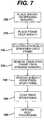
- the method of the present inventioncomprises placing a transfer sheath over a spinning mandrel and placing the radially expandable structural frame over the transfer sheath.
- a fiberis then electro-statically spun directly onto at least a portion of the structural frame to form a tubular membrane.
- the structural frame and tubular membraneform a fiber spun frame assembly.
- the fiber spun frame assemblyis removed from the spinning mandrel.
- Post processing steps to achieve particular desired characteristics or configurationsinclude forming valve cusps in the tubular membrane and forming valve flaps by thinning the membrane.
- the method of forming a tubular membrane on a radially expandable structural framecomprises placing the radially expandable structural frame over a spinning mandrel and electro-statically spinning a first fiber directly onto at least a portion of the structural frame to form a tubular membrane.
- the structural frame and tubular membraneforming a fiber spun frame assembly.
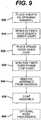
- the method of forming a tubular membrane on a radially expandable structural framecomprises placing a transfer sheath over a spinning mandrel and electro-statically spinning a first fiber directly onto at least a portion of the transfer sheath to form a first tubular membrane.
- the radially expandable structural frameis then placed over the first tubular membrane and a second fiber is electro-statically spun directly onto at least a portion of the structural frame to form a second tubular membrane.
- the combination of the first tubular membrane, structural frame and second tubular membraneforming a fiber spun frame assembly.
- the fiber spun frame assemblyis removed from the spinning mandrel.
- Post processing steps to achieve particular desired characteristics or configurationsinclude forming valve cusps in the tubular membrane and forming valve flaps by thinning the membrane.
- the fiber spun frame assemblymay be coated with a polymer, such as an elastic or elastomeric polymer.
- the tubular membranemay receive further post processing to achieve other particular desired characteristics or configurations.
- the present disclosurealso relates to a medical device having a tubular membrane structure.
- the medical devicecomprises a radially expandable structural frame and a polymer fiber membrane electro-statically spun over the structural frame.
- An outer membraneis coated over the fiber membrane, such that the outer membrane and fiber membrane combining to form the tubular membrane structure.
- the present disclosurealso relates to a medical device having a tubular membrane structure.
- the medical devicecomprises an inner membrane and an outer membrane.
- the inner membraneis formed from an electrostatically spun polymer fiber.
- a radially expandable structural frameis contracted over the inner membrane.
- the outer membraneformed from a polymer fiber membrane electrostatically spun over the structural frame, such that the inner membrane and outer membrane combining to form the tubular membrane structure.
- stent-based valves of the present disclosureprovide a method for overcoming the difficulties associated with the treatment of valve insufficiency.
- stent based venous valvesare disclosed, one of ordinary skill in the art would understand that they can be equally applied to other locations and lumens in the body, such as, for example, coronary, vascular, non-vascular and peripheral vessels, ducts, and the like, including but not limited to cardiac valves, venous valves, valves in the esophagus and at the stomach, valves in the ureter and/or the vesica, valves in the biliary passages, valves in the lymphatic system and valves in the intestines.
- the prosthetic valveis designed to be percutaneously delivered through a body lumen to a target site by a delivery catheter.
- the target sitemay be, for example, a location in the venous system adjacent to an insufficient venous valve.
- the prosthetic venous valvefunctions to assist or replace the incompetent or damaged natural valve by allowing normal blood flow (antegrade blood flow) and preventing or reducing backflow (retrograde blood flow).
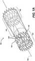
- FIG. 1AA perspective view of a prosthetic venous valve in the expanded (deployed) state is shown in Figure 1A .
- the prosthetic venous valve 100comprises a structural frame 101 and a biocompatible membrane assembly 102.
- the membrane assembly 102is comprised of a tubular membrane, valve flaps and valve cusps.
- the flaps and cuspsmay be independent components attached to the tubular membrane to form the membrane assembly 102, but are preferably part of, and integrated into, the tubular membrane.
- the valve flaps and valve cuspsare formed into the tubular membrane by processing techniques as will be discussed in greater detail below.
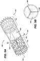
- FIG. 1Ba perspective view of the prosthetic venous valve 100 structural frame 101 is shown in Figure 1B .
- the structural frame 101consists of proximal and distal anchor structures 103, 104 connected by at least one connecting member 105. In a preferred aspect, at least three connecting members 105 are utilized.
- proximal and distalare typically used to connote a direction or position relative to a human body.
- the proximal end of a bonemay be used to reference the end of the bone that is closer to the center of the body.
- distalcan be used to refer to the end of the bone farthest from the body.
- proximal and distalare sometimes used to refer to the flow of blood to the heart, or away from the heart, respectively. Since the prosthetic valves described in this disclosure can be used in many different body lumens, including both the arterial and venous system, the use of the terms proximal and distal in this application are used to describe relative position in relation to the direction of fluid flow.
- proximal anchorin the present application describes the upstream anchor of structural frame 101 regardless of its orientation relative to the body.
- distalis used to describe the down stream anchor on structural frame 101 regardless of its orientation relative to the body.
- proximal and distalto connote a direction describe upstream (retrograde) or downstream (antegrade) respectively.
- the connecting members 105are attached between the proximal and distal anchors 103, 104 to further support the biocompatible membrane assembly 102 (not shown in Figure 1B ).
- the connecting members 105are substantially straight members, connecting the stent based proximal and distal anchors 103, 104 in a direction substantially parallel to the longitudinal axis 106. Although three connecting members 105 are shown in the illustrated aspect, this configuration should not be construed to limit the scope of the aspect.
- connecting members 105may be twisted in a helical fashion as they extend from the proximal to distal anchors 103, 104.
- This alternate aspectis illustrated in Figure 1C .
- the connection points between the connecting members 105 and the distal anchor 104, and the connecting members 105 and the proximal anchor 103are rotationally phased 180 degrees from each other to provide the helical design.
- Each connecting member 105may also be biased inward slightly toward the longitudinal centerline 106 of the stent-based anchors 103, 104, creating a structural frame 101 having an hour-glass shape with the minimum radius located substantially at the longitudinal midpoint along the connecting member 105 length.
- An hourglass shaped structural frame 101is illustrated in Figure 1D .
- the materials for the structural frame 101should exhibit excellent corrosion resistance and biocompatibility.
- the material comprising the structural frame 101should be sufficiently radiopaque and create minimal artifacts during MRI.
- the present disclosurecontemplates deployment of the prosthetic venous valve 100 by both assisted (mechanical) expansion, i.e. balloon expansion, and self-expansion means.
- the structural frames 101is made from materials that can be plastically deformed through the expansion of a mechanical assist device, such as by the inflation of a catheter based balloon.
- a mechanical assist devicesuch as by the inflation of a catheter based balloon.
- the frame 101remains substantially in the expanded shape.
- the ideal materialhas a low yield stress (to make the frame 101 deformable at manageable balloon pressures), high elastic modulus (for minimal recoil), and is work hardened through expansion for high strength.
- the most widely used material for balloon expandable structures 101is stainless steel, particularly 316L stainless steel. This material is particularly corrosion resistant with a low carbon content and additions of molybdenum and niobium. Fully annealed, stainless steel is easily deformable.
- Alternative materials for mechanically expandable structural frames 101 that maintain similar characteristics to stainless steelinclude tantalum, platinum alloys, niobium alloys, and cobalt alloys.
- other materials, such as polymers and bioabsorbable polymersmay be used for the structural frames 101.
- the materials comprising the structural frame 101should exhibit large elastic strains .
- a suitable material possessing this characteristicis Nitinol, a Nickel-Titanium alloy that can recover elastic deformations of up to 10 percent. This unusually large elastic range is commonly known as superelasticity.
- bioabsorbable polymerssuch as polydioxanone may also be used.
- Bioabsorbable materialsabsorb into the body after a period of time, leaving only the biocompatible membrane 102 in place. The period of time for the structural frame 101 to absorb may vary, but is typically sufficient to allow adequate tissue growth at the implant location to adhere to and anchor the biocompatible membrane 102.
- the structural frame 101may be fabricated using several different methods. Typically, the structural frame 101 is constructed from sheet, wire (round or flat) or tubing, but the method of fabrication generally depends on the raw material form used.
- the structural frame 101can be formed from wire using convention wire forming techniques, such as coiling, braiding, or knitting. By welding the wire at specific locations a closed-cell structure may be created. This allows for continuous production, i.e. the components of the structural frame 101, such as proximal and distal anchors 103, 104, may be cut to length from a long wire mesh tube. The connecting member 105 may then be attached to the proximal and distal anchors 103, 104 by welding or other suitable connecting means.
- convention wire forming techniquessuch as coiling, braiding, or knitting.
- the complete frame structuremay be cut from a solid tube or sheet of material, and thus the structural frame 101 would be considered a monolithic unit.
- Laser cutting, water-jet cutting and photochemical etchingare all methods that can be employed to form the structural frame 101 from sheet and tube stock.
- the disclosure of various methods for constructing the structural frame 101should not be construed as limiting.
- One of ordinary skill in the artwould understand that other construction methods may be employed to form the structural frame 101 of the prosthetic venous valve 100.
- the anchors 103, 104are stent-based structures. This configuration facilitates the percutaneous delivery of the prosthetic venous valve 100 through the vascular system in a compressed state. Once properly located, the stent-based venous valve 100 may be deployed to the expanded state.
- FIG. 2AA perspective views of a typical stent-based anchor in the expanded (deployed) state is shown in Figures 2A .
- a Z or S shaped pattern stent anchoris shown for the purpose of example, the illustration is not to be construed as limiting the scope of the disclosure.
- One of ordinary skill in the artwould understand that other stent geometries may be used.
- the stent anchors(proximal and distal anchors 103, 104 respectively) each comprise a tubular configuration of structural elements having proximal and distal open ends and defining a longitudinal axis 106 extending therebetween.
- the stent anchors 103, 104have a first diameter (not shown) for insertion into a patient and navigation through the vessels, and a second diameter D2 for deployment into the target area of a vessel, with the second diameter being greater than the first diameter.
- the stent anchors 103, 104, and thus the stent based venous valve 100may be either a mechanical (balloon) or self-expanding stent based structure.
- Each stent anchor 103, 104comprises at least one hoop structure 206 extending between the proximal and distal ends.
- the hoop structure 206includes a plurality of longitudinally arranged strut members 208 and a plurality of loop members 210 connecting adjacent struts 208. Adjacent struts 208 are connected at opposite ends in a substantially S or Z shaped pattern so as to form a plurality of cells. As previously discussed, one of ordinary skill in the art would recognize that the pattern shaped by the struts is not a limiting factor, and other shaped patterns may be used.
- the plurality of loops 210have a substantially semicircular configuration, having an inter radii 212 and outer radii 214, and are substantially symmetric about their centers.
- the inner and outer radii 212, 214 respectively,are shown in a close-up perspective view illustrated in Figure 2B .
- the connecting member 105may be connected to the proximal and distal anchors 103, 104 at various points along the structure. As illustrated in Figure 2C , the connecting members 105 are connected between the proximal end of the distal anchor 104 and the distal end of the proximal anchor 103 at the inflection point of the loop members 210. This configuration creates a "Peak-to-Peak" connection bridging the outer radii 214 of the inflection point of loop members 210 on the proximal anchor 103 with the outer radii 214 of the inflection point of the loop member 210 on the distal anchor 104.
- the connecting members 105are connected to the inflection point of loop members 210 oriented directly opposite one another, and are evenly spaced along the circumference of the tubular anchors 103, 104. This configuration facilitates the radial expansion of the prosthetic valve from the collapsed (delivered) state to the expanded (deployed) state, and provides a substantially symmetrical valve configuration.
- the connecting members 105may be connected between the distal and proximal anchors 104, 103 to create a "Peak-to-Valley" connection between the loop members 210.
- the connecting members 105are connected to the proximal end of the distal anchor 104 at the outer radii 214 of the inflection point of loop member 210, and the inner radii 212 of the inflection point of, loop member 210 on the proximal end of the proximal anchor 103.
- the connecting members 105may be connected between the distal end of the distal anchor 104 and the proximal end of the proximal anchor 103 at the inflection point of the loop members 210 as shown in Figure 2E .
- This configurationcreates a "Valley-to-Valley" connection bridging the inner radii 212 of the inflection point of loop members 210 on the proximal anchor 103 with the inner radii 212 of the inflection point of the loop member 210 on the distal anchor 104.
- the connecting members 105may be connected between the strut members 208 of the distal anchor 104 and the strut members 208 of the proximal anchor 103 as shown in Figure 2F .
- connections between the connecting members 105 and the anchors 103, 104may be made at every inflection point around the circumference of the structure; or alternatively, at a subset of the inflection points around the circumference of the structure. In other words, connected inflection points alternate with unconnected inflection points in some defined pattern.
- each stent anchormay utilize a plurality of hoop structures.
- FIG. 3shows a distal anchor having a plurality of hoop structures 306A through 306D according to another aspect of the present disclosure.
- the distal stent anchor 104may further comprise a plurality of bridge members 314 that connect adjacent hoops 306A through 306D.
- Each bridge member 314comprises two ends 316A, 316B. One end 316A, 316B of each bridge 314 is attached to one loop on one hoop.
- hoop sections 306C and 306Dfor example, each bridge member 314 is connected at end 316A to loop 310 on hoop section 306C at a point 320.
- the opposite end 316B of each bridge member 314is connected to loop 310 on hoop sections 306D at a point 321.
- the proximal and distal anchors 103, 104secure the prosthetic valve 100 to the inside wall of a body vessel such as a vein, and provide anchor points for the connecting members 105.
- the anchors 103, 104Once deployed in the desired location, the anchors 103, 104 will expand to an outside diameter slightly larger that the inside diameter of the native vessel (not shown) and remain substantially rigid in place, anchoring the valve assembly to the vessel .
- the connecting members 105preferably have an inferior radial stiffness, and will conform much more closely to the native diameter of the vessel, facilitating the operation of the biocompatible membrane assembly 102.
- the membrane assemblyis formed from a flexible membrane-like biocompatible material that is affixed to the frame structure 101.
- the membranemust be strong enough to resist tearing under normal use, yet thin enough to provide the necessary flexibility that allows the biocompatible membrane assembly 102 to open and close satisfactorily.
- FIGS. 4A and 4Bare perspective and section views, respectively, illustrating one aspect of the expanded (deployed) prosthetic venous valve assembly 100 in the open position.
- the membrane materialmay be a biological material, such as a vein or small intestine submucosa (SIS), but is preferably a synthetic material such as a polymer, for example an elastic or elastomeric polymer, including a fluoropolymer, fluoroelastomer, or a bioabsorbable material, such as a bioabsorbable polymer or bioabsorbable elastomer.
- Bioabsorbable materialsmay allow cells to grow and form a tissue membrane (or valve flaps) over the bioabsorbable membrane. The bioabsorbable membrane then absorbs into the body, leaving the tissue membrane and/or flaps in place to act as a new natural tissue valve.
- the synthetic materialmay be reinforced with a fiber, such as an electro-statically spun (ESS) fiber, porous foam, such as ePTFE, or mesh.
- ESSelectro-statically spun
- the flexible membrane like biocompatible materialis formed into a tube (membrane tubular structure 400) and placed over and around the structural frame 101.
- the membrane tubular structure 400has a first (distal) and second (proximal) ends 401, 402 respectively, and preferably also has integrated valve flaps 403 and valve cusps 404. These components together comprise the membrane assembly 102.
- the first end 401 of the membrane tubular structure 400is located between the proximal and distal anchors 103, 104, and is preferably located at the approximate longitudinal midpoint of the connecting members 105 between the two anchors 103, 104.
- the second end 402 of the membrane tubular structure 400extends proximally from the longitudinal midpoint, and is preferably located proximal to at least one half of the proximal anchor 103.
- the membrane structure 400completely covers the proximal anchor 103. This configuration allows the proximal anchor 103 to expand the membrane tubular structure 400 into the native vessel wall, anchoring the membrane tubular structure 400 in place, and providing adequate sealing against retrograde blood flow.
- the distal end 401 of the membrane tubular structure 400terminates with the valve flaps 403.
- the number of valve flaps 403is directly proportional to the number of connecting members 105 supporting the membrane tubular assembly 102.
- the valve flaps 403are sufficiently pliable and supple to easily open and close as the blood flow changes from antegrade to retrograde . When the valve flaps 403 close (during retrograde flow) the interior surfaces of the flaps 403 and/or membrane tubular structure 400 come into contact to prevent or adequately reduce retrograde blood flow.
- valve cusps 404are formed into the membrane tubular structure 400.
- the valve cusps 404are defined generally by the intersection of the connecting members 105 and membrane tubular structure 400.
- cuspsare not meant to limit the scope of this disclosure.
- the term “cusps”is often more aptly used to describe the valve members in semilunar valves, such as the aortic and pulmonary valves, this discussion refers to both the cusps of semilunar valves and the "leaflets” of venous and atrioventricular valves. Accordingly, it should be understood that the aspects discussed in relation to these valves could be applied to any type of mammalian valve, including heart valves, venous valves, peripheral valves, etc.
- valve flaps 403During retrograde flow, blood passes the leading edge of valve flaps 403 and enters the valve cusps 404. Since the membrane tubular structure 40,0 (and membrane assembly 102) are substantially sealed against the inner vessel wall by proximal anchor 103, the valve cusps 404 form a substantially fluid tight chamber. As the valve cusps 404 fill, the membrane tubular structure 400 is directed inward until the interior surfaces of the membrane tubular structure 400 contact each other, particularly along the leading edges of valve flaps 403, closing the membrane assembly 102.
- Figure 5A and 5Bshow perspective and section views, respectively, illustrating one aspect of the expanded (deployed) prosthetic venous valve assembly 100 in the closed position.
- the membrane assembly 102is normally configured in the open position, and only moves to the closed position upon retrograde blood flow. This configuration minimizes interference with blood flow (minimized blocking) and reduces turbulence at and through the valve.
- the connecting members 105 in this embodimenthave an inferior radial stiffness, and provide a natural bias against the movement of the membrane assembly 102 to the closed position. This bias assists the valve flaps 403 and valve cusps 404 when returning to the open position.
- the bias towards opening the membrane assembly 102(against closing) be sufficiently high to commence opening the valve before antegrade blood flow begins, i.e. during a point in time when the blood flow is stagnant (there is neither antegrade nor retrograde blood flow), or when minimal retrograde flow is experienced.
- valve assemblynormally configured in the closed position, biased closed, and only open upon antegrade flow.
- the membrane assembly 102is made from a flexible membrane-like biocompatible material formed into the membrane tubular structure 400.
- the membrane 400can be woven, non-woven (such as electrostatic spinning), mesh, knitted, film or porous film (such as foam) .
- the membrane assembly 102may be fixedly attached to the structural frame by many different methods, including attachment resulting from radial pressure of the structural frame 101 against the membrane assembly 102, attachment by means of a binder, heat, or chemical bond, and/or attachment by mechanical means, such as welding or suturing.
- some of the membrane assembly 102such as distal end 402 of tubular membrane 400, is slideably attached to the structural frame 101, particularly along connecting members 105. Allowing the distal end 402 to slide along the connecting members 105 may allow or improve the opening and closing of the flaps 403. The sliding movement may also assist the cusps 404 when filling and emptying.
- a limiting meansmay be integrated into the prosthetic valve 100 to limit the sliding movement of the membrane assembly 102.
- Examples of limiting meansare shown in Figures 6A to 6C .
- a stop 600(illustrated as stop 600A, 600B, and 600C in Figures 6A to 6C respectively) is integrated into the connecting member 105.
- the membrane assembly 102is wrapped around the connecting member 105 and bonded to itself to form a loop collar 605.
- the loop collar 605must be sized to inhibit the distal end 402 of the membrane assembly 102 from sliding past the stop 600.
- the connecting member 105has a thickened or "bulbous" section forming stop 600A.
- Figure 6Billustrates an undulating stop 60OB configuration.
- Figure 6Cshows the stop 600C configured as a double bulbous section. It should be noted that the various configurations illustrated in Figures 6A through 6C are exemplary. One of ordinary skill in the art would understand that other configurations of stops may used.
- the tubular membrane 400is manufactured from a fiber reinforced elastomer, such as an elastomeric fluoropolymer.
- the elastomerallows the tubular membrane 400 to be extremely thin and elastic, while the fiber provides the necessary strength.
- the method used in this invention to produce this type of reinforced membrane valveis an Electro-Static Spinning (ESS) process.
- the ESS processcan be used to form a tubular membrane on many different types of structural frames, including frames associated with stents, stent grafts, valves, including percutaneously delivered venous valve, AAA (Abdominal Aortic Aneurysm) devices, local drug delivery devices, and the like.
- the disclosure of the ESS process for forming the tubular membrane 400 on the structural frame of a stent-based venous valveis exemplary, and thus not meant to limit the scope of this invention.
- FIG. 7shows the steps for electro-statically spinning a reinforced tubular membrane onto a structural frame according to one embodiment of the present invention.
- the ESS processcomprises first placing a transfer sheath over a spinning mandrel as shown in step 700.
- the transfer sheathis a thin material that is used to prevent the ESS spun fiber from adhering to the mandrel.
- the transfer sheetmay also provide the necessary electrical conductivity to attract the ESS spun fiber.
- the transfer sheathcomprises a thin polymer tube, preferably fluoropolymer, of such a thickness that it can be easily deformed, and preferably collapsed, so that it is capable of being withdrawn conveniently from the lumen of the structural frame 101 and/or membrane tubular structure 400.
- a transfer sheathmade of other fibrous or sheet materials, such as other polymer, polymeric or metallic materials is not excluded. Most preferably, the transfer sheath will be made of an ePTFE tube.
- the ePTFE tubemay be first coated with gold on at least a portion of the interior surface before placing the tube on the mandrel. This process may be completed by coating the inside of the tube, but is preferably done by coating the exterior of the ePTFE tube and then inverting the tube so that the gold coating is on the interior surface. The process may also be completed by inverting the tube so that the interior surface to be coated is exposed on exterior of the tube, coating the now exposed interior surface, and the inverting the tube so that the interior coated surface is back on the inside of the tube.
- the spinning mandrelis electrically conducting, and more preferably, is a metal coated with Teflon ®.
- electrical conductionmay not be essential.
- the spinning mandrelmay be of any suitable material, including plastic material. Non-conductors may be used so long as the charge is capable of being transferred (i.e. bleed off) onto the transfer sheet or through the material itself.
- the spinning mandrelmay be hollow or solid, and preferably has a smooth surface to facilitate sliding between the transfer sheath, and mandrel during removal. However, it may be desirable to maintain some degree of frictional resistance between the transfer sheath and mandrel to reduce slippage between the two components during the ESS process.
- valve structural frame 101is then placed on the transfer sheath, step 710, and the ESS fiber is spun directly onto the valve structural frame 101 as shown in step 720.
- the structural frame 101is configured in the expanded or deployed state prior to placing the structural frame 101 on the spinning mandrel. This is generally the case when the structural frame 101 is of the self-expanding design.
- the expansion mechanismmay be integrated within the spinning mandrel to expand the structural frame during the spinning process.
- the expandable mandrelmay also be used for electro-statically spinning a fiber onto a self-expanding structural frame 101.
- the self-expanding structural frame 101is placed on the spinning mandrel in the expanded state, and the expansion mechanism on the expandable mandrel is mandrel activated to further radially expand the structural frame to a "super-expanded" state.
- ESS fiberis then spun directly onto the super-expanded structural frame 101.
- the larger diameter of the super-expanded structural frame 101allows more material to be deposited on the structural frame, which may result in less post processing procedures. Post processing is described in step 760.
- Electro-static spinning of a fiberis generally known in the art, and typically involves creating an electrical potential between a source component, i.e. the fiber or preferably a fiber forming liquid, and a downstream component, i.e. the spinning mandrel, transfer sheath or structural frame.
- the electrical potentialcauses the source component, typically the fiber forming liquid, to be attracted to, and thus move towards, the downstream component.
- the electrical potentialis created by providing an electrical charge to either the source or downstream component, and grounding the other component.
- the source componentwill receive an electrical charge, while the downstream component is grounded.
- a fiber forming liquidis introduced into an electric field, whereby the fiber forming liquid is caused to produce a charged fiber.
- a deviceintroducing the fiber forming liquid into the process is electrically charged, thus causing the fiber forming liquid to assume a like charge.
- the fiber forming liquidis sufficiently viscous to be extruded into the process with an extrusion device.
- the fiber forming liquidis introduced into the process, it is hardened to form the ESS fiber.
- Hardening of the liquid into an ESS fibermay be accomplished, for example, by cooling the liquid until the fiber forming liquid will not lose its fibrous shape.
- Other methods for hardening the fibermay also include hardening by introducing a chemical hardener into the fiber forming liquid, or directing an air stream over the electrically drawn fiber forming liquid stream.
- a polymeris put into solution with a solvent to form a viscous fiber forming liquid. As the fiber forming liquid is drawn from the introducer device, the solvent comes out of solution forming the polymer fiber.
- Drying techniquesmay include, for example, applying heat or airflow to or over the coated fiber spun frame assembly.
- the solventmay dry naturally without applying artificial drying techniques.
- the viscosity of the fiber forming liquidmay be adjusted based on the material used for the source component, and the percent solids desired as the source component reaches the downstream component. Typical concentrations range from 2 to 100 percent. The choice of concentration depends on the material, its molecular weight, the solvent efficiency, and temperature. The concentration and temperature also control the diameter of the fiber. These viscosities will typically produce a fiber at the downstream component having percent solids in the range of about 95 percent to about 100 percent, and preferably over 99 percent. This is desirable in order to produce structures that contain entangled or point bonded fibers. Concentrations lower than 95 percent can be used if it is desired to allow filaments to fuse together into a sheet-like barrier structure.
- the hardened fiberis then collected onto the structural frame.
- Collecting of the fiberinvolves attracting the ESS fiber to the downstream component (i.e. spinning mandrel, transfer sheath or structural frame) of the ESS system, while spinning the downstream component.
- a downstream componentis grounded to complete the electric potential between the source and downstream component, and thus attract the ESS fiber.
- a downstream componentmay be electrically charged to attract the ESS fiber where the source component is grounded.
- various combinations of downstream componentsmay be electrically charged to enhance electrical conductivity and reduce the time it takes to build up the ESS layer.
- Particular ESS fibers suitable for this spinning processinclude fluoropolymers, such as a crystalline fluoropolymer with an 85/15% (weight/weight ratio) of vinylidene fluoride/hexafluoropropylene (VDF/HFP).
- fluoropolymerssuch as a crystalline fluoropolymer with an 85/15% (weight/weight ratio) of vinylidene fluoride/hexafluoropropylene (VDF/HFP).
- Solvay Solef® 21508 and Kynarflex 2750-01are two such examples.
- bioabsorbable polymerssuch as polyglycolic acid, polylactic acid, poly (paradioxanone), polycaprolactone, poly (trimethylenecarbonate) and their copolymers
- semicrystalline bioelastomerssuch as 60/40%(weight/weight ratio) of polylactic acid / polycaprolactone (PLA/PCL), 65/35 (weight/weight ratio) of polyglycolic acid/polycaprolactone (PGA/PCL), or nonabsorbable siliconized polyurethane, non-siliconized polyurethanes, siliconized polyureaurethane, including siliconized polyureaurethane end capped with silicone or fluorine end groups, or natural polymers in combination thereof.
- PLA/PCLpolycaprolactone
- PGA/PCLpolyglycolic acid/polycaprolactone
- siliconized polyureaurethaneincluding siliconized polyureaurethane end capped with silicone or fluorine end groups, or natural polymers in combination thereof.
- the spinning processshould be continued until an ESS fiber tube, or fabric, is formed having a wall thickness of between 5 ⁇ m and 100 ⁇ m or more, preferably, approximately 20 ⁇ m.
- the ESS fiber spun structural frame 101is then removed from the spinning mandrel, step 730, before the transfer sheath is removed from the fiber spun frame, step 740. Once this step is completed, the fiber spun structural frame is coated in a solution of polymer, such as fluoroelastomer, as shown in step 750.
- the fiber spun structural frameis first dip coated in a polymer solution, and then spun about its longitudinal axis to more evenly distribute the coating.
- the fiber spun structural frameis not first removed from the spinning mandrel. Instead, the frame/mandrel assembly is dip coated, and spun before removing the fiber spun structural frame from the spinning mandrel. Still other methods for coating the fiber spun structural frame would be obvious to one of skill in the art.
- the coating processmay act to encapsulate and attach at least a portion of the spun ESS reinforcement fiber to the structural frame 101. It should be noted that it in some embodiments of the invention, some movement between the membrane assembly 102 and the structural frame 101 is desired. Accordingly, not all of the ESS fiber spun structural frame may be coated.
- the coating processmay also remove some porosity of the membrane material. However, it may be desirable to maintain some porosity in particular embodiments to promote biological cell grown on and within the membrane tubular structure.
- the coating solutionpreferably comprises a polymer put into solution with a solvent. As the solvent evaporates, the polymer comes out of solution forming the coating layer. Accordingly, for the process to work properly, the solvent used in the coating solution should not dissolve or alter the ESS fibers being coated.
- a coating solution of 60/40% VDF/HFP in methanolhas been found to be a suitable solution for coating an ESS fiber comprised of 85/15% VDF/HFP.
- the polymer comprising the coatingis Daikin's Dai-El G701BP, which is a 60/40% VDF/HFP.
- Daikin's Dai-El T630a thermoplastic elastomer based on vinylidene fluoride/hexafluoropropylene/tetrafluoroethylene (VDF/HFP/TFE) can also be used.
- VDF/HFP/TFEvinylidene fluoride/hexafluoropropylene/tetrafluoroethylene
- other materials having suitable characteristicsmay be used for the coating, for example, other polymers, such as siliconized polyurethane, including Polymer Technology Group's Pursil, Carbosil, Purspan and Purspan F.
- the coating processmay be repeated until the desired characteristics and thickness are achieved.
- a thickness of between 12 ⁇ m. and 100 ⁇ m and preferably between 25 ⁇ m and 50 ⁇ mhas been found to be acceptable.
- the coating processmay take place to achieve particular desired characteristics or configurations. This may include creating the final form of the membrane assembly 102.
- the post processing stepis shown as optional step 760 in Figure 7 .
- the post processing step 760is used to form or shape, a valve cusp, for example, similar to cusp 404, in the membrane tubular structure 400.
- post processingchanges the characteristics of the membrane tubular structure 400 by thickening or thinning the membrane in particular locations. Thickening the membrane may add rigidity and reinforcement to a particular area. Thinning the membrane may make the membrane more pliable, which is a desirable characteristic for the valve flaps 403.
- Still other post processing proceduresmay be applied to change the physical shape of the membrane tubular structure 400, for example, by forming the loop collar 605 along the distal edge of membrane tubular structure 400.
- the loop collar 605may assist in controlling the movement (translational and circumferential) of the membrane assembly 102 along the connecting members 105.
- the loop collars 605may also reduce fatigue and tear stresses in the membrane.
- FIGS 8A and 8Bshow an example of the result of a post processing step that forms a loop collar 605 according to one embodiment of the present invention.
- the membrane tubular structure 400is wrapped around at least one element of structural frame 101 (connecting member 105) and bonded to itself at bond point 800.
- FIG. 9Another method for electro-statically spinning a tubular membrane onto a radially expandable structural frame according to another embodiment of the present invention is shown in Figure 9 .
- this alternative methodprovides an ESS spun membrane on the inside, as well as the outside of the structural frame.
- the inner and outer ESS spun membranesmay mechanically adhere to each other, and in a sense encapsulated the structural frame.
- This configurationprovides some additional features, including having a smoother interior surface that reduces turbulence, improves flow dynamics and lowers the chance of thrombosis formation.
- the ESS processcomprises first placing a transfer sheath over a spinning mandrel as shown in step 900. It should be noted that, although not forming part of the invention, under certain circumstances it may not be necessary to use the transfer sheath. Such circumstances may include, for example, where the spinning mandrel is electro-statically conducting and has a surface or surface treatment that will prevent the ESS spun fiber from adhering to the mandrel.
- An ESS fiberis then spun directly onto the transfer sheath creating an inner coat membrane as shown in step 910.
- the ESS processshould continue until an ESS tube is formed having a wall thickness of between 2 ⁇ m and 50 ⁇ m or more, and preferably, approximately 20 ⁇ m.
- the inner coat membranecovers some or all of the interior surface of structural frame 101.
- the structural frame 101is then radially expanded, and placed over the inner coat membrane on the spinning mandrel as shown in step 920. Expansion of the structural frame 101 may be achieved by several different methods.
- One methodincludes taking advantage of the thermal and shape memory characteristics of particular materials. For example, shape memory materials, such as Nitinol, possess little or no recoil ability when cooled, but exhibit a high degree of memory, i.e.
- the structural frame 101is sized such that when configured in the expanded or deployed state, it will fit tightly over the inner coat membrane on the spinning mandrel.
- the structural frame 101may have to be radially expanded ("super-expanded") to a diameter slightly larger than the expanded deployed state to allow the structural frame 101 to fit over the inner coat membrane.
- ESS fiberis spun directly onto the structural frame, as shown in step 930, to form a top-coat membrane.
- the ESS processshould continue until the top-coat membrane tube is formed having a wall thickness of between 2pm and 50pm or more, and preferably, approximately 20pm.
- the top-coat membranemay cover and adhere to the inner coat membrane through the interstitial spaces between the elements that comprise the structural frame 101.
- the structural frame 101is configured on the mandrel in the expanded deployed state prior to spinning the top-coat membrane.
- the structural frame 101with the inner coat and top coat membranes, is then removed from the spinning mandrel, as shown in step 940, and coated with a solution of highly elastic polymer as shown in step 950.
- the coating processmay be achieved using several different coating methods, including spin coating, spray coating, dip coating, chemical vapor deposition, plasma coating, co-extrusion coating and insert molding.
- a representative elastomeric polymeris a fluoroelastomer.
- the coating processmay be repeated until the desired characteristics and thickness are achieved.
- FIG. 10Another exemplary method for forming the membrane material over and around the structural frame 101 is shown in Figure 10 .
- this methodis presented in the context of a prosthetic valve application.
- the methodmay be applied generally to any application where a micro-cellular foam or pourous material, particularly an ePTFE membrane, needs to be placed over and around a radially expandable structural frame.
- Exemplary structural framesmay include stents, stents grafts, valves (including percutaneously delivered venous valves), AAA (Abdominal Aortic Aneurysm) devices, local drug delivery devices, and the like. Accordingly, the disclosed device is not meant to limit the scope of the method.
- a tubular structureis fabricated from a polymer material that can be processed such that it exhibits an expanded cellular structure, preferably expanded Polytetrafluoroethylene (ePTFE).
- ePTFEexpanded Polytetrafluoroethylene
- the ePTFE tubingis made by expanding Polytetrafluoroethylene (PTFE) tubing, under controlled conditions, as is well known in the art. This process alters the physical properties that make it satisfactory for use in medical devices.
- PTFEPolytetrafluoroethylene
- the methodcomprises first placing a transfer sheath over a mandrel as shown in step 1000.
- the transfer sheathis a thin material that is used to prevent the tubing and coating from adhering to the mandrel.
- the transfer sheathmay be made of sheet metal, metal foil, or polymer sheet, such as for example Polytetrafluoroethylene (PTFE).
- PTFEPolytetrafluoroethylene
- the transfer sheathwill be made of a material that can be easily deformed, and preferably collapsed so that it can be withdrawn conveniently from the lumen of the tube once the process is complete.
- the transfer sheath/mandrel combinationare then coated in a solution of highly elastic polymer, such as fluoroelastomer, as shown in step 1010, to form an inner membrane.
- highly elastic polymersuch as fluoroelastomer
- the coatingmay be applied using various methods, including, for example, spin coating, spray coating, dip coating, chemical vapor deposition, plasma coating, co-extrusion coating and insert molding.
- the coating solutioncomprises a polymer put into solution with a solvent, such as methanol.
- a solventsuch as methanol.
- most solventscan be used with expanded Polytetrafluoroethylene (ePTFE).
- the polymer comprising the coatingincludes Daikin's Dai-El T630, a thermoplastic elastomer based on vinylidene fluoride/hexafluoropropylene/tetrafluoroethylene (VDF/HFP/TFE) and blends thereof.
- VDF/HFP/TFEvinylidene fluoride/hexafluoropropylene/tetrafluoroethylene
- Other preferred polymersinclude siliconized polyurethanes, including silicone-urethane copolymers, and blends thereof.
- Silicone-urethane copolymerscan consist of segmented polyetherurethane with aromatic urea as hard segments and poly (tetramethyleneoxide) [PTMO] as soft segments. Silicone (20 to 25%) is added by replacing PTMO with polydimethylsiloxane, and fluorine (0.5 to 2%) can be added by surface-modifying end groups. Again, one of ordinary skill in the art would understand that other materials having suitable characteristics may be used for the coating, for example, other polymers and blends thereof.
- Preferred siliconized polyurethanesinclude Polymer Technology Group's Pursil, Carbosil, Purspan and Purspan F.
- the coating processshould continue until the inner membrane achieves a wall thickness of between 6pm and 100 ⁇ m or more, preferably between 12 ⁇ m to 25 ⁇ m.
- a polymer tubepreferably an ePTFE tube
- a polymer tubemay be expanded and placed over the sheath/mandrel combination (step 1015), before being contracted (step 1020).
- Expansionmay be by any suitable expansion means known in the art, including mechanical expansion, such as by means of a balloon expansion device or expandable cage, expansion by utilizing a tapered mandrel (i.e. sliding the polymer tube over a tapered mandrel of increasing diameter), etc.
- other meansmay be used in conjunction with the expansion means to assist placing the tube over the sheath mandrel combination. These assist means may include, for example, thermally expanding the tube with heat, or chemically expanding the tube with a solvent. These methods are known in the art.
- Contraction of the tubeis typically done by reversing the method used to expand the tube.
- ePTFEis naturally elastic. If the ePTFE tube was expanded by a mechanical expansion means, removing the expansion means would allow the ePTFE tube to contract towards it pre-expansion configuration. In addition the contraction of the tube may be enhanced by applying heat or chemicals (solvents).
- the whole assemblymay be coated with a solution of highly elastic polymer, such as fluoroelastomer as shown in step 1025 to form the inner membrane.
- a solution of highly elastic polymersuch as fluoroelastomer as shown in step 1025 to form the inner membrane.
- the coating processis similar to that shown in step 1010 above, and may be achieved by any method known in the art capable of achieving the desired result, including spin coating, spray coating, dip coating, chemical vapor deposition, plasma coating, co-extrusion coating and insert molding.
- step 1025should continue until the inner membrane described in the alternate embodiment is coated with a polymer base having a wall thickness of between 6 ⁇ m and 100 ⁇ m or more, preferably between 12 ⁇ m to 25 ⁇ m.
- the structural frame 101is then radially expanded and positioned over the inner membrane as shown in step 1030.
- the structural frame 101may be radially expanded using any know expansion means, including a balloon expansion device or frame expansion device.
- the structural frame 101is constructed from a shape memory alloy, such as Nitinol.
- Nitinolcharacteristically holds a deformed shaped when cooled, and returns to its original shape when heated. Accordingly, it is possible to hold a Nitinol structural frame 101 in the radially expanded state by cooling the frame before the expansion means is removed. This will facilitate placement of the Nitinol structural frame over the inner membrane.
- the structural frame 101may then be radially contracted over the inner membrane, as shown in step 1040. It is desirable to maintain a slight interference fit between the structural frame 101 and the inner membrane.
- the method to radially contract the structural frame 101may depend on the material and type of construction of the structural frame 101, and is not meant to limit the scope of the invention. As described above, a structural frame 101 constructed from a shape memory alloy, such as Nitinol, can be radially contracted (to the pre-expanded and cooled size) by heating. Depending on the material used, other methods that may also be employed to radially contract the structural frame include, simply removing the expansion means providing the radial expansion force, or applying a compressive force about the structural frame 101. Still other methods to radially contract the structural frame 101 would be obvious to one of skill in the art.
- a second polymer tubepreferably an ePTFE tube
- ePTFE tubeis expanded and placed over the structural frame, as shown in step 1050, forming an outer membrane.
- the tubeis then contracted into position as shown in step 1060.
- the tubemay be expanded by several different means, including mechanical, thermal, or chemical (solvents) expansion.
- contraction of the tubemay be accomplished by the methods described in step 1020.
- each tubeshould have a wall thickness of between 25 ⁇ m and 50pm before expansion; yielding a wall thickness of between 6 ⁇ m and 10 ⁇ m after expansion and placement. It should be noted that these membranes may or may not be bonded together. If only a single ePTFE tube is used for the outer membrane only, as described in step 1050 (not following alternate steps 1015 through 1025), the tube should have a wall thickness before expansion of between 50 ⁇ m and 100 ⁇ m; yielding a wall thickness after expansion of between 12 ⁇ m and 20pm.
- the inner and outer membranescombine to for a membrane structure.
- the membrane structurewould represent membrane tubular structure 400, while the structural frame would represent the structural frame 101.
- the assemblymay be optionally coated with a solution of a highly elastic polymer, such as an elastomeric polymer, as shown in step 1070.
- a highly elastic polymersuch as an elastomeric polymer
- the coatingmay be applied by any method known in the art, including spin coating, spray coating, dip coating, chemical vapor deposition, plasma coating, co-extrusion coating and insert molding.
- the coating solutionmay be a fluoroelastomer.
- the coatingis Daikin Dai-El T630, a thermoplastic elastomer based on vinylidene fluoride/hexafluoropropylene/tetrafluoroethylene (VDF/HFP/TFE) and blends thereof.
- VDF/HFP/TFEvinylidene fluoride/hexafluoropropylene/tetrafluoroethylene
- other materials having suitable characteristicsmight be used for the coating, for example, other polymers, such as siliconized polyurethane.
- the coating processshould continue until the coating achieves a wall thickness of between 6 ⁇ m and 100 ⁇ m or more, preferably between 12 ⁇ m to 25 ⁇ m.
- This post processing stepis shown as optional step 1080 in Figure 10 .
- the post processing step 1080may be used to form or shape valve cusps, similar to cusps 404, or valve flaps, such as flaps 403, in the membrane structure.
- post processingmay change the characteristics of the membrane structure by thickening or thinning the membrane in particular locations. Thickening the membrane may add rigidity and reinforcement to a particular area. Thinning the membrane may make the membrane more pliable.
- Still other post processing proceduresmay change the physical shape of the membrane structure, for example, by forming the loop collar 605 along the distal edge of membrane assembly 102.
- the loop collar 605may assist in controlling the translational and circumferential movement of the membrane assembly 102 along the connecting members 105.
- the loop collars 605may also reduce fatigue and tear stresses in the membrane.
- therapeutic or pharmaceutic agentsmay be added to any component of the device during fabrication, including, for example, the ESS fiber, polymer or coating solution, membrane tube, structural frame or inner and outer membrane, to treat any number of conditions.
- .therapeutic or pharmaceutic agentsmay be applied to the device, such as in the form of a drug or drug eluting layer, or surface treatment after the device has been formed.
- the therapeutic and pharmaceutic agentsmay include any one or more of the following: antiproliferative/antimitotic agents including natural products such as vinca alkaloids (i.e.
- paclitaxeli.e. etoposide, teniposide
- antibioticsdactinomycin (actinomycin D) daunorubicin, doxorubicin and idarubicin
- anthracyclinesmitoxantrone, bleomycins, plicamycin (mithramycin) and mitomycin
- enzymesL-asparaginase which systemically metabolizes L-asparagine and deprives cells which do not have the capacity to synthesize their own asparagine
- antiplatelet agentssuch as G(GP) ll b /lll a inhibitors and vitronectin receptor antagonists
- antiproliferative/antimitotic alkylating agentssuch as nitrogen mustards (mechlorethamine, cyclophosphamide and analogs, melphalan, chlorambucil), ethylenimine
- anticoagulantsheparin, synthetic heparin salts and other inhibitors of thrombin
- fibrinolytic agentssuch as tissue plasminogen activator, streptokinase and urokinase), aspirin, dipyridamole, ticlopidine, clopidogrel, abciximab
- antimigratoryantisecretory (breveldin)
- antiinflammatorysuch as adrenocortical steroids (cortisol, cortisone, fludrocortisone, prednisone, prednisolone, 6 ⁇ -methylprednisolone, triamcinolone, betamethasone, and dexamethasone), non-steroidal agents (salicylic acid derivatives i.e.
- the present disclosurerelates to a medical device, particularly a stent-based valve, to be delivered and deployed in a body lumen or vessel.
- a medical deviceparticularly a stent-based valve
- One typical use of this disclosed stent-based valveis to assist or replace insufficient venous valves in the vascular system.
- the vein 1100may be any of the tubular branching vessels that carry blood from the capillaries toward the heart (antegrade blood flow) .
- Vein 1100comprises a vein wall 1101 formed of three layers.
- the innermost layer of the vein wall 1101is the Tunica Intima 1102.
- the Intima 1102is a simple epithelium made up of a single layer of flat epithelial cells comprising connective and elastic tissue.
- the second and main portion of the vein wall 1101is the Tunica Media 1103.
- the Media 1103is made up of a combination of smooth muscle and elastic tissue.
- the smooth muscle portion of the Media 1103is usually larger than the other layers and consequently provides support to counteract outward radial force caused by blood pressure within the vessel. To some extent, the Media 1103 also provides support against the radial expansion of the prosthetic venous valve 100.
- the third layer of the vein wall 1101is the outer surface or the Tunica adventitia 1104.
- the adventitia* 1104is comprised generally of connective tissue, but may also include arties and veins that supply the tissues of the vessel.
- veins greater than approximately two (2) millimeters in diameter located below the heartoften have one or more natural valves 1105 at intervals to prevent reflux of the blood (retrograde blood flow) .
- These venous valves 1105are necessary to counteract the effect of gravitation force on antegrade blood flow.
- FIG. 12A transverse cross-sectional view of an open prosthetic venous valve 100 deployed into vein 1100 during antegrade blood flow is shown in Figure 12 .
- the correct placement of the anchors 103, 104may result in mounds of tissue 1200 protruding between the strut members comprising the distal anchor 104 after the anchor 104 has been embedded in the Tunica Intima 1102.
- These tissue mounts 1200retain endothelial cells that can provide for the re-endothelialization of the vessel wall. Endothelial regeneration of the vessel wall may cause endothelial cells to migrate to, and over the anchor 104 members, resulting in a thin tissue layer encapsulating the anchor 104 struts. This endothelialization may assist in anchoring the prosthetic venous valve 100 in place.
- the structural frame 101may be coated or treated with a therapeutic or pharmaceutic agent, such as an anti-reste otic (antiproliferative) .
- a therapeutic or pharmaceutic agentsuch as an anti-reste otic (antiproliferative)
- the membrane assembly 102may be coated or impregnated with a therapeutic or pharmaceutic agent.
- FIG. 12depicts the biocompatible membrane assembly 102 located on the exterior surface of the proximal anchor 103 and connecting members 105.
- the correct placement of the proximal anchor 103expands the exterior surface of the biocompatible membrane assembly 102 into the Tunica Intima 1102, creating a substantially fluid tight seal between the membrane assembly 102 and vein wall 1101.
- This sealing effectsubstantially eliminates blood flow around the exterior of the prosthetic venous valve 100.
- the sealing effectfacilitates the membrane assembly 102 closing during retrograde blood flow.
Landscapes
- Health & Medical Sciences (AREA)
- Engineering & Computer Science (AREA)
- Biomedical Technology (AREA)
- Life Sciences & Earth Sciences (AREA)
- Cardiology (AREA)
- Veterinary Medicine (AREA)
- Transplantation (AREA)
- Oral & Maxillofacial Surgery (AREA)
- Animal Behavior & Ethology (AREA)
- General Health & Medical Sciences (AREA)
- Public Health (AREA)
- Chemical & Material Sciences (AREA)
- Vascular Medicine (AREA)
- Heart & Thoracic Surgery (AREA)
- Medicinal Chemistry (AREA)
- Textile Engineering (AREA)
- Dermatology (AREA)
- Chemical Kinetics & Catalysis (AREA)
- Epidemiology (AREA)
- General Chemical & Material Sciences (AREA)
- Physics & Mathematics (AREA)
- Optics & Photonics (AREA)
- Mechanical Engineering (AREA)
- Manufacturing & Machinery (AREA)
- Molecular Biology (AREA)
- Prostheses (AREA)
Description
- The present invention relates to a method for forming the medical device. In particular, the present invention relates to a method of forming the tubular membrane on the radially expandable structural frame.
- The human body has numerous biological valves that control fluid flow through body lumens and vessels. For example the circulatory system has various heart valves that allow the heart to act as a pump by controlling the flow of blood through the heart chambers veins, and aorta. In addition, the venous system has numerous venous valves that help control the flow of blood back to the heart, particularly from the lower extremities.
- These valves can become incompetent or damaged by disease, for example, phlebitis, injury, or the result of an inherited malformation. For example, heart valves are subject to disorders, such as mitral stenosis, mitral regurgitation, aortic stenosis, aortic regurgitation, mitral valve prolapse and tricuspid stenosis. These disorder are potentially life threatening. Similarly, incompetent or damaged venous valves usually leak, allowing the blood to improperly flow back down through veins away from the heart (regurgitation reflux or retrograde blood flow). Blood can then stagnate in sections of certain veins, and in particular, the veins in the lower extremities. This stagnation of blood raises blood pressure and dilates the veins and venous valves. The dilation of one vein may in turn disrupt the proper function of other venous valves in a cascading manner, leading to chronic venous insufficiency.
- Numerous therapies have been advanced to treat symptoms and to correct incompetent valves. Less invasive procedures include compression, elevation and wound care. However, these treatments tend to be somewhat expensive and are not curative. Other procedures involve surgical intervention to repair, reconstruct or replace the incompetent or damaged valves, particularly heart valves.
- Surgical procedures for incompetent or damaged venous valves include valvuloplasty, transplantation, and transposition of veins. However, these surgical procedures provide somewhat limited results. The leaflets of venous valves are generally thin, and once the valve becomes incompetent or destroyed, any repair provides only marginal relief.
- As an alternative to surgical intervention, drug therapy to correct valvular incompetence has been utilized. Currently, however, there are no effective drug therapies available.
- Other means and methods for treating and/or correcting damaged or incompetent valves include utilizing xenograft valve transplantation (monocusp bovine pericardium), prosthetic/bioprosthetic heart valves and vascular grafts, and artificial venous valves. These means have all had somewhat limited results.
- What is needed is an artificial endovascular valve for the replacement of incompetent biological human valves, particularly heart and venous valves. These valves may also find use in artificial hearts and artificial heart assist pumps used in conjunction with heart transplants.
US 6,309,413 discloses an endoluminal graft which is said to be both expandable and supportive either in a longitudinal form or in a bifurcated form. The graft is said to expand between a first diameter and a second, larger diameter. The support component is said to be an expandable stent endoprosthesis. A cover, liner, or a liner, or both a cover and a liner are said to be applied to the endoprosthesis in the form of a stretchable wall material that is porous, elastomeric and biocompatible in order to allow normal cellular invasion upon implantation, without stenosis, when the expandable and supportive graft is at its second diameter. It is said that the elastomeric wall material is preferably a polycarbonate urethane.WO 02/26139 US 2002/133,183 disclose medical devices and implantable medical devices that may be coated in order to minimize or substantially eliminate a biological organism's reaction to the introduction of the medical device to the organism. The medical devices are preferably coated with any number of biocompatible materials. Therapeutic drugs, agents or compounds may be mixed with the biocompatible materials and affixed to at least a portion of the medical device. These therapeutic drugs, agents or compounds are said to further reduce a biological organism's reaction to the introduction of the medical device to the organism. Various materials and coating methodologies are said to be utilized to maintain the drugs, agents or compounds on the medical device until delivered and positioned.US 4,323,525 discloses a process for electrostatically spinning fiber forming material. The spun fiber is collected on a removable sheath on a rotating mandrel. The sheath is electroconductive. The tubular spun fiber product is separated from the sheath.EP 1 192 957- The present invention relates to a method of forming a tubular membrane on a radially expandable structural frame. An example of a medical device having a radially expandable structural frame and a tubular membrane is a stent-based valve.
- The present invention provides a method of forming the tubular membrane on the structural frame. In accordance with one aspect, the method of the present invention comprises placing a transfer sheath over a spinning mandrel and placing the radially expandable structural frame over the transfer sheath. A fiber is then electro-statically spun directly onto at least a portion of the structural frame to form a tubular membrane. The structural frame and tubular membrane form a fiber spun frame assembly. The fiber spun frame assembly is removed from the spinning mandrel.
- Post processing steps to achieve particular desired characteristics or configurations include forming valve cusps in the tubular membrane and forming valve flaps by thinning the membrane.
- In an aspect of the present disclosure, the method of forming a tubular membrane on a radially expandable structural frame comprises placing the radially expandable structural frame over a spinning mandrel and electro-statically spinning a first fiber directly onto at least a portion of the structural frame to form a tubular membrane. The structural frame and tubular membrane forming a fiber spun frame assembly.
- In another embodiment of the present invention, the method of forming a tubular membrane on a radially expandable structural frame comprises placing a transfer sheath over a spinning mandrel and electro-statically spinning a first fiber directly onto at least a portion of the transfer sheath to form a first tubular membrane. The radially expandable structural frame is then placed over the first tubular membrane and a second fiber is electro-statically spun directly onto at least a portion of the structural frame to form a second tubular membrane. The combination of the first tubular membrane, structural frame and second tubular membrane forming a fiber spun frame assembly. The fiber spun frame assembly is removed from the spinning mandrel. Post processing steps to achieve particular desired characteristics or configurations include forming valve cusps in the tubular membrane and forming valve flaps by thinning the membrane.
- In each described embodiment, the fiber spun frame assembly may be coated with a polymer, such as an elastic or elastomeric polymer. In addition, the tubular membrane may receive further post processing to achieve other particular desired characteristics or configurations.
- The present disclosure also relates to a medical device having a tubular membrane structure. The medical device comprises a radially expandable structural frame and a polymer fiber membrane electro-statically spun over the structural frame. An outer membrane is coated over the fiber membrane, such that the outer membrane and fiber membrane combining to form the tubular membrane structure.
- The present disclosure also relates to a medical device having a tubular membrane structure. The medical device comprises an inner membrane and an outer membrane. The inner membrane is formed from an electrostatically spun polymer fiber. A radially expandable structural frame is contracted over the inner membrane. The outer membrane formed from a polymer fiber membrane electrostatically spun over the structural frame, such that the inner membrane and outer membrane combining to form the tubular membrane structure.
Figure 1A shows a perspective view of a prosthetic venous valve in the deployed state.Figure 1B shows a perspective view of the prosthetic venous valve structural frame in the deployed state.Figure 1C shows a perspective view of the prosthetic venous valve structural frame having helical connecting members.Figure 1D shows a perspective view of the prosthetic venous valve structural frame having an hourglass shape.Figure 2A shows a perspective view of the proximal stent-based anchor in the expanded deployed state.Figure 2B shows a close-up perspective view of a loop having inner and outer radii.Figure 2C shows a perspective view of the prosthetic venous valve structural frame having connecting members connected between the proximal and distal anchors in a peak-to-peak configuration.Figure 2D shows a perspective view of the prosthetic venous valve structural frame having connecting members connected between the distal and proximal anchors in a peak-to-valley configuration.Figure 2E shows a perspective view of the prosthetic venous valve structural frame having connecting members connected between the distal and proximal anchors in a valley-to-valley configuration.Figure 2F shows a perspective view of the prosthetic venous valve structural frame having connecting members connected between the distal and proximal anchors along the strut members.Figure 3 shows a perspective view of the distal stent anchor having a plurality of hoop structures.Figure 4A is a perspective view illustrating one aspect of the expanded (deployed) prosthetic venous valve assembly in the open position.Figure 4B is a section view illustrating one aspect of the expanded (deployed) prosthetic venous valve assembly in the open position.Figure 5A is a perspective view illustrating one aspect of the expanded (deployed) prosthetic venous valve assembly in the closed position.Figure 5B is a section view illustrating one aspect of the expanded (deployed) prosthetic venous valve assembly in the closed position.Figure 6A is a perspective view illustrating a membrane limiting means.Figure 6B is a perspective view illustrating a membrane limiting means.Figure 6C is a perspective view illustrating a membrane limiting means.Figure 7 is a flow diagram illustrating the steps to electro-statically spin a tubular membrane on a structural frame according to one embodiment of the present invention.Figure 8A is section view illustrating the expanded (deployed) prosthetic venous valve assembly in the open position after some post processing.Figure 8B shows a close-up section view illustrating a portion of the valve assembly after some post processing.Figure 9 is a flow diagram illustrating the steps to electro-statically spin a tubular membrane on a structural frame according to one embodiment of the present invention.Figure 10 is a flow diagram illustrating the steps to place a tubular membrane over a structural frame according to one aspect of the present disclosure.Figure 11 illustrates a sectioned view of a typical vein.Figure 12 shows a transverse cross-sectional view of the vein and deployed prosthetic venous valve.- The stent-based valves of the present disclosure provide a method for overcoming the difficulties associated with the treatment of valve insufficiency. Although stent based venous valves are disclosed, one of ordinary skill in the art would understand that they can be equally applied to other locations and lumens in the body, such as, for example, coronary, vascular, non-vascular and peripheral vessels, ducts, and the like, including but not limited to cardiac valves, venous valves, valves in the esophagus and at the stomach, valves in the ureter and/or the vesica, valves in the biliary passages, valves in the lymphatic system and valves in the intestines.
- In accordance with one aspect of the present disclosure, the prosthetic valve is designed to be percutaneously delivered through a body lumen to a target site by a delivery catheter. The target site may be, for example, a location in the venous system adjacent to an insufficient venous valve. Once deployed the prosthetic venous valve functions to assist or replace the incompetent or damaged natural valve by allowing normal blood flow (antegrade blood flow) and preventing or reducing backflow (retrograde blood flow).
- A perspective view of a prosthetic venous valve in the expanded (deployed) state is shown in
Figure 1A . The prostheticvenous valve 100 comprises astructural frame 101 and abiocompatible membrane assembly 102. In one aspect, themembrane assembly 102 is comprised of a tubular membrane, valve flaps and valve cusps. The flaps and cusps may be independent components attached to the tubular membrane to form themembrane assembly 102, but are preferably part of, and integrated into, the tubular membrane. In a preferred aspect, the valve flaps and valve cusps are formed into the tubular membrane by processing techniques as will be discussed in greater detail below. - For clarity, a perspective view of the prosthetic
venous valve 100structural frame 101 is shown inFigure 1B . Thestructural frame 101 consists of proximal anddistal anchor structures member 105. In a preferred aspect, at least three connectingmembers 105 are utilized. - It should be noted that the terms proximal and distal are typically used to connote a direction or position relative to a human body. For example, the proximal end of a bone may be used to reference the end of the bone that is closer to the center of the body. Conversely, the term distal can be used to refer to the end of the bone farthest from the body. In the vasculature, proximal and distal are sometimes used to refer to the flow of blood to the heart, or away from the heart, respectively. Since the prosthetic valves described in this disclosure can be used in many different body lumens, including both the arterial and venous system, the use of the terms proximal and distal in this application are used to describe relative position in relation to the direction of fluid flow. For example, the use of the term proximal anchor in the present application describes the upstream anchor of
structural frame 101 regardless of its orientation relative to the body. Conversely, the use of the term distal is used to describe the down stream anchor onstructural frame 101 regardless of its orientation relative to the body. Similarly, the use of the terms proximal and distal to connote a direction describe upstream (retrograde) or downstream (antegrade) respectively. - The connecting
members 105 are attached between the proximal anddistal anchors Figure 1B ). In one aspect, the connectingmembers 105 are substantially straight members, connecting the stent based proximal anddistal anchors longitudinal axis 106. Although three connectingmembers 105 are shown in the illustrated aspect, this configuration should not be construed to limit the scope of the aspect. - Alternatively, the connecting
members 105 may be twisted in a helical fashion as they extend from the proximal todistal anchors Figure 1C . Specifically, the connection points between the connectingmembers 105 and thedistal anchor 104, and the connectingmembers 105 and theproximal anchor 103, are rotationally phased 180 degrees from each other to provide the helical design. - Each connecting
member 105 may also be biased inward slightly toward thelongitudinal centerline 106 of the stent-basedanchors structural frame 101 having an hour-glass shape with the minimum radius located substantially at the longitudinal midpoint along the connectingmember 105 length. An hourglass shapedstructural frame 101 is illustrated inFigure 1D . - The materials for the
structural frame 101 should exhibit excellent corrosion resistance and biocompatibility. In addition, the material comprising thestructural frame 101 should be sufficiently radiopaque and create minimal artifacts during MRI. - The present disclosure contemplates deployment of the prosthetic
venous valve 100 by both assisted (mechanical) expansion, i.e. balloon expansion, and self-expansion means. In embodiments where the prostheticvenous valve 100 is deployed by mechanical (balloon) expansion, thestructural frames 101 is made from materials that can be plastically deformed through the expansion of a mechanical assist device, such as by the inflation of a catheter based balloon. When the balloon is deflated, theframe 101 remains substantially in the expanded shape. Accordingly, the ideal material has a low yield stress (to make theframe 101 deformable at manageable balloon pressures), high elastic modulus (for minimal recoil), and is work hardened through expansion for high strength. The most widely used material for balloonexpandable structures 101 is stainless steel, particularly 316L stainless steel. This material is particularly corrosion resistant with a low carbon content and additions of molybdenum and niobium. Fully annealed, stainless steel is easily deformable. - Alternative materials for mechanically expandable
structural frames 101 that maintain similar characteristics to stainless steel include tantalum, platinum alloys, niobium alloys, and cobalt alloys. In addition other materials, such as polymers and bioabsorbable polymers may be used for thestructural frames 101. - Where the prosthetic
venous valve 100 is self-expanding, the materials comprising thestructural frame 101 should exhibit large elastic strains . A suitable material possessing this characteristic is Nitinol, a Nickel-Titanium alloy that can recover elastic deformations of up to 10 percent. This unusually large elastic range is commonly known as superelasticity. - The disclosure of various materials comprising the structural frame should not be construed as limiting the scope of the disclosure. One of ordinary skill in the art would understand that other material possessing similar characteristics may also be used in the construction of the prosthetic
venous valve 100. For example, bioabsorbable polymers, such as polydioxanone may also be used. Bioabsorbable materials absorb into the body after a period of time, leaving only thebiocompatible membrane 102 in place. The period of time for thestructural frame 101 to absorb may vary, but is typically sufficient to allow adequate tissue growth at the implant location to adhere to and anchor thebiocompatible membrane 102. - The
structural frame 101 may be fabricated using several different methods. Typically, thestructural frame 101 is constructed from sheet, wire (round or flat) or tubing, but the method of fabrication generally depends on the raw material form used. - The
structural frame 101 can be formed from wire using convention wire forming techniques, such as coiling, braiding, or knitting. By welding the wire at specific locations a closed-cell structure may be created. This allows for continuous production, i.e. the components of thestructural frame 101, such as proximal anddistal anchors member 105 may then be attached to the proximal anddistal anchors - In addition, the complete frame structure may be cut from a solid tube or sheet of material, and thus the
structural frame 101 would be considered a monolithic unit. Laser cutting, water-jet cutting and photochemical etching are all methods that can be employed to form thestructural frame 101 from sheet and tube stock. - As discussed above, the disclosure of various methods for constructing the
structural frame 101 should not be construed as limiting. One of ordinary skill in the art would understand that other construction methods may be employed to form thestructural frame 101 of the prostheticvenous valve 100. - In one aspect of the disclosure, the
anchors venous valve 100 through the vascular system in a compressed state. Once properly located, the stent-basedvenous valve 100 may be deployed to the expanded state. - A perspective views of a typical stent-based anchor in the expanded (deployed) state is shown in
Figures 2A . Although a Z or S shaped pattern stent anchor is shown for the purpose of example, the illustration is not to be construed as limiting the scope of the disclosure. One of ordinary skill in the art would understand that other stent geometries may be used. - The stent anchors (proximal and
distal anchors longitudinal axis 106 extending therebetween. The stent anchors 103, 104 have a first diameter (not shown) for insertion into a patient and navigation through the vessels, and a second diameter D2 for deployment into the target area of a vessel, with the second diameter being greater than the first diameter. The stent anchors 103, 104, and thus the stent basedvenous valve 100, may be either a mechanical (balloon) or self-expanding stent based structure. - Each
stent anchor hoop structure 206 extending between the proximal and distal ends. Thehoop structure 206 includes a plurality of longitudinally arrangedstrut members 208 and a plurality ofloop members 210 connectingadjacent struts 208.Adjacent struts 208 are connected at opposite ends in a substantially S or Z shaped pattern so as to form a plurality of cells. As previously discussed, one of ordinary skill in the art would recognize that the pattern shaped by the struts is not a limiting factor, and other shaped patterns may be used. The plurality ofloops 210 have a substantially semicircular configuration, having aninter radii 212 andouter radii 214, and are substantially symmetric about their centers. The inner andouter radii Figure 2B . - The connecting
member 105 may be connected to the proximal anddistal anchors Figure 2C , the connectingmembers 105 are connected between the proximal end of thedistal anchor 104 and the distal end of theproximal anchor 103 at the inflection point of theloop members 210. This configuration creates a "Peak-to-Peak" connection bridging theouter radii 214 of the inflection point ofloop members 210 on theproximal anchor 103 with theouter radii 214 of the inflection point of theloop member 210 on thedistal anchor 104. - Preferably the connecting
members 105 are connected to the inflection point ofloop members 210 oriented directly opposite one another, and are evenly spaced along the circumference of the tubular anchors 103, 104. This configuration facilitates the radial expansion of the prosthetic valve from the collapsed (delivered) state to the expanded (deployed) state, and provides a substantially symmetrical valve configuration. - Alternatively, the connecting
members 105 may be connected between the distal andproximal anchors loop members 210. In this configuration, illustrated inFigure 2D , the connectingmembers 105 are connected to the proximal end of thedistal anchor 104 at theouter radii 214 of the inflection point ofloop member 210, and theinner radii 212 of the inflection point of,loop member 210 on the proximal end of theproximal anchor 103. - In a further aspect, the connecting
members 105 may be connected between the distal end of thedistal anchor 104 and the proximal end of theproximal anchor 103 at the inflection point of theloop members 210 as shown inFigure 2E . This configuration creates a "Valley-to-Valley" connection bridging theinner radii 212 of the inflection point ofloop members 210 on theproximal anchor 103 with theinner radii 212 of the inflection point of theloop member 210 on thedistal anchor 104. - In still a further aspect, the connecting
members 105 may be connected between thestrut members 208 of thedistal anchor 104 and thestrut members 208 of theproximal anchor 103 as shown inFigure 2F . - In any of the above described configurations, the connections between the connecting
members 105 and theanchors - Although stent anchors 103, 104 incorporating a singular hoop structure are shown in the aspect illustrated in
Figures 2A though 2F, each stent anchor may utilize a plurality of hoop structures. Figures 3 shows a distal anchor having a plurality ofhoop structures 306A through 306D according to another aspect of the present disclosure. In the illustrated aspect, thedistal stent anchor 104 may further comprise a plurality ofbridge members 314 that connectadjacent hoops 306A through 306D. Eachbridge member 314 comprises twoends end bridge 314 is attached to one loop on one hoop. Usinghoop sections 306C and 306D for example, eachbridge member 314 is connected atend 316A toloop 310 onhoop section 306C at apoint 320. Similarly, theopposite end 316B of eachbridge member 314 is connected toloop 310 on hoop sections 306D at apoint 321.- The proximal and
distal anchors prosthetic valve 100 to the inside wall of a body vessel such as a vein, and provide anchor points for the connectingmembers 105. Once deployed in the desired location, theanchors members 105 preferably have an inferior radial stiffness, and will conform much more closely to the native diameter of the vessel, facilitating the operation of thebiocompatible membrane assembly 102. - The membrane assembly is formed from a flexible membrane-like biocompatible material that is affixed to the
frame structure 101. The membrane must be strong enough to resist tearing under normal use, yet thin enough to provide the necessary flexibility that allows thebiocompatible membrane assembly 102 to open and close satisfactorily. Figure 4A and 4B are perspective and section views, respectively, illustrating one aspect of the expanded (deployed) prostheticvenous valve assembly 100 in the open position. The membrane material may be a biological material, such as a vein or small intestine submucosa (SIS), but is preferably a synthetic material such as a polymer, for example an elastic or elastomeric polymer, including a fluoropolymer, fluoroelastomer, or a bioabsorbable material, such as a bioabsorbable polymer or bioabsorbable elastomer. Bioabsorbable materials may allow cells to grow and form a tissue membrane (or valve flaps) over the bioabsorbable membrane. The bioabsorbable membrane then absorbs into the body, leaving the tissue membrane and/or flaps in place to act as a new natural tissue valve.- To achieve the necessary flexibility and strength of the
membrane assembly 102, the synthetic material may be reinforced with a fiber, such as an electro-statically spun (ESS) fiber, porous foam, such as ePTFE, or mesh. The flexible membrane like biocompatible material is formed into a tube (membrane tubular structure 400) and placed over and around thestructural frame 101. The membranetubular structure 400 has a first (distal) and second (proximal) ends 401, 402 respectively, and preferably also has integrated valve flaps 403 andvalve cusps 404. These components together comprise themembrane assembly 102. - The
first end 401 of the membranetubular structure 400 is located between the proximal anddistal anchors members 105 between the twoanchors second end 402 of the membranetubular structure 400 extends proximally from the longitudinal midpoint, and is preferably located proximal to at least one half of theproximal anchor 103. In one aspect of the disclosure, themembrane structure 400 completely covers theproximal anchor 103. This configuration allows theproximal anchor 103 to expand the membranetubular structure 400 into the native vessel wall, anchoring the membranetubular structure 400 in place, and providing adequate sealing against retrograde blood flow. - The
distal end 401 of the membranetubular structure 400 terminates with the valve flaps 403. The number of valve flaps 403 is directly proportional to the number of connectingmembers 105 supporting themembrane tubular assembly 102. The valve flaps 403 are sufficiently pliable and supple to easily open and close as the blood flow changes from antegrade to retrograde . When the valve flaps 403 close (during retrograde flow) the interior surfaces of theflaps 403 and/or membranetubular structure 400 come into contact to prevent or adequately reduce retrograde blood flow. - To facilitate closing the valve flaps 403 during retrograde blood flow,
valve cusps 404 are formed into the membranetubular structure 400. Thevalve cusps 404 are defined generally by the intersection of the connectingmembers 105 and membranetubular structure 400. - The use of the term "cusps" is not meant to limit the scope of this disclosure. Although the term "cusps" is often more aptly used to describe the valve members in semilunar valves, such as the aortic and pulmonary valves, this discussion refers to both the cusps of semilunar valves and the "leaflets" of venous and atrioventricular valves. Accordingly, it should be understood that the aspects discussed in relation to these valves could be applied to any type of mammalian valve, including heart valves, venous valves, peripheral valves, etc.
- During retrograde flow, blood passes the leading edge of valve flaps 403 and enters the
valve cusps 404. Since the membrane tubular structure 40,0 (and membrane assembly 102) are substantially sealed against the inner vessel wall byproximal anchor 103, thevalve cusps 404 form a substantially fluid tight chamber. As thevalve cusps 404 fill, the membranetubular structure 400 is directed inward until the interior surfaces of the membranetubular structure 400 contact each other, particularly along the leading edges of valve flaps 403, closing themembrane assembly 102.Figure 5A and 5B show perspective and section views, respectively, illustrating one aspect of the expanded (deployed) prostheticvenous valve assembly 100 in the closed position. - In a preferred aspect of the disclosure, the
membrane assembly 102 is normally configured in the open position, and only moves to the closed position upon retrograde blood flow. This configuration minimizes interference with blood flow (minimized blocking) and reduces turbulence at and through the valve. The connectingmembers 105 in this embodiment have an inferior radial stiffness, and provide a natural bias against the movement of themembrane assembly 102 to the closed position. This bias assists the valve flaps 403 andvalve cusps 404 when returning to the open position. - Depending on the application, it may also be desired that the bias towards opening the membrane assembly 102 (against closing) be sufficiently high to commence opening the valve before antegrade blood flow begins, i.e. during a point in time when the blood flow is stagnant (there is neither antegrade nor retrograde blood flow), or when minimal retrograde flow is experienced.
- In other applications, it may be desirable to have the valve assembly normally configured in the closed position, biased closed, and only open upon antegrade flow.
- As earlier described, the
membrane assembly 102 is made from a flexible membrane-like biocompatible material formed into the membranetubular structure 400. Themembrane 400 can be woven, non-woven (such as electrostatic spinning), mesh, knitted, film or porous film (such as foam) . - The
membrane assembly 102 may be fixedly attached to the structural frame by many different methods, including attachment resulting from radial pressure of thestructural frame 101 against themembrane assembly 102, attachment by means of a binder, heat, or chemical bond, and/or attachment by mechanical means, such as welding or suturing. Preferably some of themembrane assembly 102, such asdistal end 402 oftubular membrane 400, is slideably attached to thestructural frame 101, particularly along connectingmembers 105. Allowing thedistal end 402 to slide along the connectingmembers 105 may allow or improve the opening and closing of theflaps 403. The sliding movement may also assist thecusps 404 when filling and emptying. - In some applications, excessive sliding movement of the
membrane assembly 102 is undesirable. In these aspects, a limiting means may be integrated into theprosthetic valve 100 to limit the sliding movement of themembrane assembly 102. Examples of limiting means are shown inFigures 6A to 6C . In each aspect a stop 600 (illustrated asstop Figures 6A to 6C respectively) is integrated into the connectingmember 105. Themembrane assembly 102 is wrapped around the connectingmember 105 and bonded to itself to form aloop collar 605. Theloop collar 605 must be sized to inhibit thedistal end 402 of themembrane assembly 102 from sliding past the stop 600. InFigure 6A , the connectingmember 105 has a thickened or "bulbous"section forming stop 600A.Figure 6B illustrates an undulating stop 60OB configuration. Similarly,Figure 6C shows thestop 600C configured as a double bulbous section. It should be noted that the various configurations illustrated inFigures 6A through 6C are exemplary. One of ordinary skill in the art would understand that other configurations of stops may used. - In one embodiment of the invention the
tubular membrane 400 is manufactured from a fiber reinforced elastomer, such as an elastomeric fluoropolymer. The elastomer allows thetubular membrane 400 to be extremely thin and elastic, while the fiber provides the necessary strength. The method used in this invention to produce this type of reinforced membrane valve is an Electro-Static Spinning (ESS) process. - The ESS process can be used to form a tubular membrane on many different types of structural frames, including frames associated with stents, stent grafts, valves, including percutaneously delivered venous valve, AAA (Abdominal Aortic Aneurysm) devices, local drug delivery devices, and the like. The disclosure of the ESS process for forming the
tubular membrane 400 on the structural frame of a stent-based venous valve is exemplary, and thus not meant to limit the scope of this invention. Figure 7 shows the steps for electro-statically spinning a reinforced tubular membrane onto a structural frame according to one embodiment of the present invention. The ESS process comprises first placing a transfer sheath over a spinning mandrel as shown instep 700. The transfer sheath is a thin material that is used to prevent the ESS spun fiber from adhering to the mandrel. In instances where the mandrel itself is not electrically conducting, the transfer sheet may also provide the necessary electrical conductivity to attract the ESS spun fiber.- In one embodiment of the invention, the transfer sheath comprises a thin polymer tube, preferably fluoropolymer, of such a thickness that it can be easily deformed, and preferably collapsed, so that it is capable of being withdrawn conveniently from the lumen of the
structural frame 101 and/or membranetubular structure 400. The use of a transfer sheath made of other fibrous or sheet materials, such as other polymer, polymeric or metallic materials is not excluded. Most preferably, the transfer sheath will be made of an ePTFE tube. - To enhance electrical conductivity and reduce the time it takes to build up the ESS layer, the ePTFE tube may be first coated with gold on at least a portion of the interior surface before placing the tube on the mandrel. This process may be completed by coating the inside of the tube, but is preferably done by coating the exterior of the ePTFE tube and then inverting the tube so that the gold coating is on the interior surface. The process may also be completed by inverting the tube so that the interior surface to be coated is exposed on exterior of the tube, coating the now exposed interior surface, and the inverting the tube so that the interior coated surface is back on the inside of the tube.
- It should be noted that, although not forming part of the invention, under certain circumstances it may not be necessary to use the transfer sheath. Such circumstances may include, for example, where the spinning mandrel is electro-statically conducting and has a surface or surface treatment that will prevent the ESS spun fiber from adhering to the mandrel.
- In a preferred embodiment, the spinning mandrel is electrically conducting, and more preferably, is a metal coated with Teflon ®. However, electrical conduction may not be essential. In such embodiments the spinning mandrel may be of any suitable material, including plastic material. Non-conductors may be used so long as the charge is capable of being transferred (i.e. bleed off) onto the transfer sheet or through the material itself.
- The spinning mandrel may be hollow or solid, and preferably has a smooth surface to facilitate sliding between the transfer sheath, and mandrel during removal. However, it may be desirable to maintain some degree of frictional resistance between the transfer sheath and mandrel to reduce slippage between the two components during the ESS process.
- The valve
structural frame 101 is then placed on the transfer sheath,step 710, and the ESS fiber is spun directly onto the valvestructural frame 101 as shown instep 720. Preferably, thestructural frame 101 is configured in the expanded or deployed state prior to placing thestructural frame 101 on the spinning mandrel. This is generally the case when thestructural frame 101 is of the self-expanding design. In other embodiments, such as balloon-expandable designs, the expansion mechanism may be integrated within the spinning mandrel to expand the structural frame during the spinning process. - The expandable mandrel may also be used for electro-statically spinning a fiber onto a self-expanding
structural frame 101. In such instances, the self-expandingstructural frame 101 is placed on the spinning mandrel in the expanded state, and the expansion mechanism on the expandable mandrel is mandrel activated to further radially expand the structural frame to a "super-expanded" state. ESS fiber is then spun directly onto the super-expandedstructural frame 101. The larger diameter of the super-expandedstructural frame 101 allows more material to be deposited on the structural frame, which may result in less post processing procedures. Post processing is described instep 760. - Electro-static spinning of a fiber is generally known in the art, and typically involves creating an electrical potential between a source component, i.e. the fiber or preferably a fiber forming liquid, and a downstream component, i.e. the spinning mandrel, transfer sheath or structural frame. The electrical potential causes the source component, typically the fiber forming liquid, to be attracted to, and thus move towards, the downstream component.
- The electrical potential is created by providing an electrical charge to either the source or downstream component, and grounding the other component. Preferably, the source component will receive an electrical charge, while the downstream component is grounded.
- Many different methods are known in the art for producing an electrical charge on a source component. In one embodiment, a fiber forming liquid is introduced into an electric field, whereby the fiber forming liquid is caused to produce a charged fiber. In another, more preferred embodiment, a device (introducer device) introducing the fiber forming liquid into the process is electrically charged, thus causing the fiber forming liquid to assume a like charge.
- Several methods may be used to introduce the fiber forming liquid into the process, including spraying the fiber forming liquid from a nozzle, or injecting the fiber forming liquid from a needle, orifice or drip tube. In a preferred embodiment, the fiber forming liquid is sufficiently viscous to be extruded into the process with an extrusion device.
- Once the fiber forming liquid is introduced into the process, it is hardened to form the ESS fiber. Hardening of the liquid into an ESS fiber may be accomplished, for example, by cooling the liquid until the fiber forming liquid will not lose its fibrous shape. Other methods for hardening the fiber may also include hardening by introducing a chemical hardener into the fiber forming liquid, or directing an air stream over the electrically drawn fiber forming liquid stream. In a preferred embodiment, a polymer is put into solution with a solvent to form a viscous fiber forming liquid. As the fiber forming liquid is drawn from the introducer device, the solvent comes out of solution forming the polymer fiber.
- Various drying techniques may be applied to evaporate the solvent and bring the polymer out of solutions. Drying techniques may include, for example, applying heat or airflow to or over the coated fiber spun frame assembly. In addition, the solvent may dry naturally without applying artificial drying techniques.
- The viscosity of the fiber forming liquid may be adjusted based on the material used for the source component, and the percent solids desired as the source component reaches the downstream component. Typical concentrations range from 2 to 100 percent. The choice of concentration depends on the material, its molecular weight, the solvent efficiency, and temperature. The concentration and temperature also control the diameter of the fiber. These viscosities will typically produce a fiber at the downstream component having percent solids in the range of about 95 percent to about 100 percent, and preferably over 99 percent. This is desirable in order to produce structures that contain entangled or point bonded fibers. Concentrations lower than 95 percent can be used if it is desired to allow filaments to fuse together into a sheet-like barrier structure.
- The hardened fiber is then collected onto the structural frame. Collecting of the fiber involves attracting the ESS fiber to the downstream component (i.e. spinning mandrel, transfer sheath or structural frame) of the ESS system, while spinning the downstream component. In a preferred embodiment, where the source component is electrically charged, a downstream component is grounded to complete the electric potential between the source and downstream component, and thus attract the ESS fiber. In other embodiments, a downstream component may be electrically charged to attract the ESS fiber where the source component is grounded. In still other embodiments, various combinations of downstream components may be electrically charged to enhance electrical conductivity and reduce the time it takes to build up the ESS layer.
- Particular ESS fibers suitable for this spinning process include fluoropolymers, such as a crystalline fluoropolymer with an 85/15% (weight/weight ratio) of vinylidene fluoride/hexafluoropropylene (VDF/HFP). Solvay Solef® 21508 and Kynarflex 2750-01 are two such examples. However, one of skill in the art would understand that any material possessing the desired characteristics may be used, including, for example: bioabsorbable polymers, such as polyglycolic acid, polylactic acid, poly (paradioxanone), polycaprolactone, poly (trimethylenecarbonate) and their copolymers; and semicrystalline bioelastomers, such as 60/40%(weight/weight ratio) of polylactic acid / polycaprolactone (PLA/PCL), 65/35 (weight/weight ratio) of polyglycolic acid/polycaprolactone (PGA/PCL), or nonabsorbable siliconized polyurethane, non-siliconized polyurethanes, siliconized polyureaurethane, including siliconized polyureaurethane end capped with silicone or fluorine end groups, or natural polymers in combination thereof. It should be noted that poly(trimethylenecarbonate) can not be spun as a homopolymer.
- The spinning process should be continued until an ESS fiber tube, or fabric, is formed having a wall thickness of between 5µm and 100µm or more, preferably, approximately 20µm. The ESS fiber spun
structural frame 101 is then removed from the spinning mandrel,step 730, before the transfer sheath is removed from the fiber spun frame,step 740. Once this step is completed, the fiber spun structural frame is coated in a solution of polymer, such as fluoroelastomer, as shown instep 750. - Several different methods may be utilized to perform the coating process on the fiber spun structural frame, including spray coating with an air or airless sprayer, dip coating, chemical vapor deposition, plasma coating, co-extrusion coating, spin coating and insert molding. In still another preferred embodiment, the fiber spun structural frame is first dip coated in a polymer solution, and then spun about its longitudinal axis to more evenly distribute the coating. In this embodiment, the fiber spun structural frame is not first removed from the spinning mandrel. Instead, the frame/mandrel assembly is dip coated, and spun before removing the fiber spun structural frame from the spinning mandrel. Still other methods for coating the fiber spun structural frame would be obvious to one of skill in the art.
- The coating process may act to encapsulate and attach at least a portion of the spun ESS reinforcement fiber to the
structural frame 101. It should be noted that it in some embodiments of the invention, some movement between themembrane assembly 102 and thestructural frame 101 is desired. Accordingly, not all of the ESS fiber spun structural frame may be coated. - The coating process may also remove some porosity of the membrane material. However, it may be desirable to maintain some porosity in particular embodiments to promote biological cell grown on and within the membrane tubular structure.
- The coating solution preferably comprises a polymer put into solution with a solvent. As the solvent evaporates, the polymer comes out of solution forming the coating layer. Accordingly, for the process to work properly, the solvent used in the coating solution should not dissolve or alter the ESS fibers being coated. By way of example, a coating solution of 60/40% VDF/HFP in methanol (methanol being the solvent) has been found to be a suitable solution for coating an ESS fiber comprised of 85/15% VDF/HFP.
- In one embodiment of the invention, the polymer comprising the coating is Daikin's Dai-El G701BP, which is a 60/40% VDF/HFP. In addition, Daikin's Dai-El T630, a thermoplastic elastomer based on vinylidene fluoride/hexafluoropropylene/tetrafluoroethylene (VDF/HFP/TFE) can also be used. Again, one of ordinary skill in the art would understand that other materials having suitable characteristics may be used for the coating, for example, other polymers, such as siliconized polyurethane, including Polymer Technology Group's Pursil, Carbosil, Purspan and Purspan F.
- The coating process may be repeated until the desired characteristics and thickness are achieved. For venous valves a thickness of between 12µm. and 100µm and preferably between 25µm and 50µm has been found to be acceptable.
- Once the coating process is complete some post processing of the membrane
tubular structure 400 may take place to achieve particular desired characteristics or configurations. This may include creating the final form of themembrane assembly 102. The post processing step is shown asoptional step 760 inFigure 7 . - The
post processing step 760 is used to form or shape, a valve cusp, for example, similar tocusp 404, in the membranetubular structure 400. In addition, post processing changes the characteristics of the membranetubular structure 400 by thickening or thinning the membrane in particular locations. Thickening the membrane may add rigidity and reinforcement to a particular area. Thinning the membrane may make the membrane more pliable, which is a desirable characteristic for the valve flaps 403. Still other post processing procedures may be applied to change the physical shape of the membranetubular structure 400, for example, by forming theloop collar 605 along the distal edge of membranetubular structure 400. Theloop collar 605 may assist in controlling the movement (translational and circumferential) of themembrane assembly 102 along the connectingmembers 105. Theloop collars 605 may also reduce fatigue and tear stresses in the membrane. Figures 8A and 8B show an example of the result of a post processing step that forms aloop collar 605 according to one embodiment of the present invention. To achieve this result, the membranetubular structure 400 is wrapped around at least one element of structural frame 101 (connecting member 105) and bonded to itself atbond point 800.- Another method for electro-statically spinning a tubular membrane onto a radially expandable structural frame according to another embodiment of the present invention is shown in
Figure 9 . Although similar to the process described above, this alternative method provides an ESS spun membrane on the inside, as well as the outside of the structural frame. The inner and outer ESS spun membranes may mechanically adhere to each other, and in a sense encapsulated the structural frame. This configuration provides some additional features, including having a smoother interior surface that reduces turbulence, improves flow dynamics and lowers the chance of thrombosis formation. - Similar to the embodiment described earlier, the ESS process comprises first placing a transfer sheath over a spinning mandrel as shown in
step 900. It should be noted that, although not forming part of the invention, under certain circumstances it may not be necessary to use the transfer sheath. Such circumstances may include, for example, where the spinning mandrel is electro-statically conducting and has a surface or surface treatment that will prevent the ESS spun fiber from adhering to the mandrel. - An ESS fiber is then spun directly onto the transfer sheath creating an inner coat membrane as shown in
step 910. The ESS process should continue until an ESS tube is formed having a wall thickness of between 2µm and 50µm or more, and preferably, approximately 20µm. As previously stated, the inner coat membrane covers some or all of the interior surface ofstructural frame 101. Thestructural frame 101 is then radially expanded, and placed over the inner coat membrane on the spinning mandrel as shown instep 920. Expansion of thestructural frame 101 may be achieved by several different methods. One method includes taking advantage of the thermal and shape memory characteristics of particular materials. For example, shape memory materials, such as Nitinol, possess little or no recoil ability when cooled, but exhibit a high degree of memory, i.e. the ability to return to a configured shape, when heated. Cooling the Nitinolstructural frame 101 before expansion allows the structural frame to remain in the expanded configuration until being heated. Accordingly, the Nitinolstructural frame 101 can be cooled, expanded, and then placed over the inner coat membrane. Once in place, the structural frame can be heated to activate the Nitinol memory characteristics, causing the Nitinolstructural frame 101 to contract to the pre-expansion size and configuration. - The
structural frame 101 is sized such that when configured in the expanded or deployed state, it will fit tightly over the inner coat membrane on the spinning mandrel. To fit thestructural frame 101 over the inner coat membrane, thestructural frame 101 may have to be radially expanded ("super-expanded") to a diameter slightly larger than the expanded deployed state to allow thestructural frame 101 to fit over the inner coat membrane. - Once the
structural frame 101 is placed over the inner coat membrane, another ESS fiber is spun directly onto the structural frame, as shown instep 930, to form a top-coat membrane. The ESS process should continue until the top-coat membrane tube is formed having a wall thickness of between 2pm and 50pm or more, and preferably, approximately 20pm. The top-coat membrane may cover and adhere to the inner coat membrane through the interstitial spaces between the elements that comprise thestructural frame 101. - As stated in an earlier described embodiment of the invention, the
structural frame 101 is configured on the mandrel in the expanded deployed state prior to spinning the top-coat membrane. In other embodiments, it may be desirable to expand (super expand) thestructural frame 101 on the spinning mandrel during or prior to the spinning process. This procedure may alter the configuration and properties of the spun membrane, resulting in less post processing of the membrane. Post processing is described instep 960. - The
structural frame 101, with the inner coat and top coat membranes, is then removed from the spinning mandrel, as shown instep 940, and coated with a solution of highly elastic polymer as shown instep 950. As stated previously, the coating process may be achieved using several different coating methods, including spin coating, spray coating, dip coating, chemical vapor deposition, plasma coating, co-extrusion coating and insert molding. - As previously described, a representative elastomeric polymer is a fluoroelastomer. The coating process may be repeated until the desired characteristics and thickness are achieved. For a venous valve application, a thickness of between 12µm and 100µm, and preferably between 25µm and 50µm, has been found to be acceptable.
- Once the coating process is complete, some post processing of the tubular membrane may take place, as shown as an
optional step 960 inFigure 9 . - Although each of the above described ESS methods spin the fiber directly on to the structural frame, one of ordinary skill in the art would understand that, although not forming part of the invention, a tubular membrane may also be spun separately, and then placed over the
structural frame 101 by known methods. - Another exemplary method for forming the membrane material over and around the
structural frame 101 is shown inFigure 10 . As described earlier, this method is presented in the context of a prosthetic valve application. However, the method may be applied generally to any application where a micro-cellular foam or pourous material, particularly an ePTFE membrane, needs to be placed over and around a radially expandable structural frame. Exemplary structural frames may include stents, stents grafts, valves (including percutaneously delivered venous valves), AAA (Abdominal Aortic Aneurysm) devices, local drug delivery devices, and the like. Accordingly, the disclosed device is not meant to limit the scope of the method. - In this example, a tubular structure is fabricated from a polymer material that can be processed such that it exhibits an expanded cellular structure, preferably expanded Polytetrafluoroethylene (ePTFE). The ePTFE tubing is made by expanding Polytetrafluoroethylene (PTFE) tubing, under controlled conditions, as is well known in the art. This process alters the physical properties that make it satisfactory for use in medical devices. However, one of ordinary skill in the art would understand that other materials that possess the necessary characteristics could also be used.
- The method comprises first placing a transfer sheath over a mandrel as shown in
step 1000. As described earlier, the transfer sheath is a thin material that is used to prevent the tubing and coating from adhering to the mandrel. The transfer sheath may be made of sheet metal, metal foil, or polymer sheet, such as for example Polytetrafluoroethylene (PTFE). Preferably, the transfer sheath will be made of a material that can be easily deformed, and preferably collapsed so that it can be withdrawn conveniently from the lumen of the tube once the process is complete. - The transfer sheath/mandrel combination are then coated in a solution of highly elastic polymer, such as fluoroelastomer, as shown in
step 1010, to form an inner membrane. As stated previously, the coating may be applied using various methods, including, for example, spin coating, spray coating, dip coating, chemical vapor deposition, plasma coating, co-extrusion coating and insert molding. - In one aspect, the coating solution comprises a polymer put into solution with a solvent, such as methanol. In addition, most solvents can be used with expanded Polytetrafluoroethylene (ePTFE). Preferably, the polymer comprising the coating includes Daikin's Dai-El T630, a thermoplastic elastomer based on vinylidene fluoride/hexafluoropropylene/tetrafluoroethylene (VDF/HFP/TFE) and blends thereof. Other preferred polymers include siliconized polyurethanes, including silicone-urethane copolymers, and blends thereof. Silicone-urethane copolymers can consist of segmented polyetherurethane with aromatic urea as hard segments and poly (tetramethyleneoxide) [PTMO] as soft segments. Silicone (20 to 25%) is added by replacing PTMO with polydimethylsiloxane, and fluorine (0.5 to 2%) can be added by surface-modifying end groups. Again, one of ordinary skill in the art would understand that other materials having suitable characteristics may be used for the coating, for example, other polymers and blends thereof.
Preferred siliconized polyurethanes include Polymer Technology Group's Pursil, Carbosil, Purspan and Purspan F. - The coating process should continue until the inner membrane achieves a wall thickness of between 6pm and 100µm or more, preferably between 12µm to 25µm.
- In an alternate embodiment, a polymer tube, preferably an ePTFE tube, may be expanded and placed over the sheath/mandrel combination (step 1015), before being contracted (step 1020). Expansion may be by any suitable expansion means known in the art, including mechanical expansion, such as by means of a balloon expansion device or expandable cage, expansion by utilizing a tapered mandrel (i.e. sliding the polymer tube over a tapered mandrel of increasing diameter), etc. In addition other means may be used in conjunction with the expansion means to assist placing the tube over the sheath mandrel combination. These assist means may include, for example, thermally expanding the tube with heat, or chemically expanding the tube with a solvent. These methods are known in the art.
- Contraction of the tube is typically done by reversing the method used to expand the tube. For example, ePTFE is naturally elastic. If the ePTFE tube was expanded by a mechanical expansion means, removing the expansion means would allow the ePTFE tube to contract towards it pre-expansion configuration. In addition the contraction of the tube may be enhanced by applying heat or chemicals (solvents).
- Once the tube is expanded, over the sheath/mandrel, the whole assembly may be coated with a solution of highly elastic polymer, such as fluoroelastomer as shown in
step 1025 to form the inner membrane. The coating process is similar to that shown instep 1010 above, and may be achieved by any method known in the art capable of achieving the desired result, including spin coating, spray coating, dip coating, chemical vapor deposition, plasma coating, co-extrusion coating and insert molding. - The coating process described in
step 1025 should continue until the inner membrane described in the alternate embodiment is coated with a polymer base having a wall thickness of between 6µm and 100µm or more, preferably between 12µm to 25µm. - The
structural frame 101 is then radially expanded and positioned over the inner membrane as shown instep 1030. Thestructural frame 101 may be radially expanded using any know expansion means, including a balloon expansion device or frame expansion device. In one embodiment of the invention, thestructural frame 101 is constructed from a shape memory alloy, such as Nitinol. As previously described, Nitinol characteristically holds a deformed shaped when cooled, and returns to its original shape when heated. Accordingly, it is possible to hold a Nitinolstructural frame 101 in the radially expanded state by cooling the frame before the expansion means is removed. This will facilitate placement of the Nitinol structural frame over the inner membrane. - The
structural frame 101 may then be radially contracted over the inner membrane, as shown instep 1040. It is desirable to maintain a slight interference fit between thestructural frame 101 and the inner membrane. The method to radially contract thestructural frame 101 may depend on the material and type of construction of thestructural frame 101, and is not meant to limit the scope of the invention. As described above, astructural frame 101 constructed from a shape memory alloy, such as Nitinol, can be radially contracted (to the pre-expanded and cooled size) by heating. Depending on the material used, other methods that may also be employed to radially contract the structural frame include, simply removing the expansion means providing the radial expansion force, or applying a compressive force about thestructural frame 101. Still other methods to radially contract thestructural frame 101 would be obvious to one of skill in the art. - Once the
structural frame 101 is contracted over the inner membrane, a second polymer tube, preferably an ePTFE tube, is expanded and placed over the structural frame, as shown instep 1050, forming an outer membrane. The tube is then contracted into position as shown instep 1060. As described earlier, the tube may be expanded by several different means, including mechanical, thermal, or chemical (solvents) expansion. Similarly, contraction of the tube may be accomplished by the methods described instep 1020. - In aspects where two separate ePTFE tubes are used for the inner and outer membranes, as described in
steps alternate steps 1015 through 1025), the tube should have a wall thickness before expansion of between 50µm and 100µm; yielding a wall thickness after expansion of between 12µm and 20pm. - The inner and outer membranes combine to for a membrane structure. In the valve example described above, the membrane structure would represent membrane
tubular structure 400, while the structural frame would represent thestructural frame 101. - Once the membrane structure is formed, some or all of the assembly may be optionally coated with a solution of a highly elastic polymer, such as an elastomeric polymer, as shown in
step 1070. The coating may be applied by any method known in the art, including spin coating, spray coating, dip coating, chemical vapor deposition, plasma coating, co-extrusion coating and insert molding. - As described earlier (see step 1010) the coating solution may be a fluoroelastomer. In one embodiment of the invention, the coating is Daikin Dai-El T630, a thermoplastic elastomer based on vinylidene fluoride/hexafluoropropylene/tetrafluoroethylene (VDF/HFP/TFE) and blends thereof. Again, one of ordinary skill in the art would understand that other materials having suitable characteristics might be used for the coating, for example, other polymers, such as siliconized polyurethane.
- The coating process should continue until the coating achieves a wall thickness of between 6µm and 100µm or more, preferably between 12µm to 25µm.
- Once the coating process is complete, some post processing of the membrane structure may take place to achieve particular desired characteristics or configurations. This post processing step is shown as
optional step 1080 inFigure 10 . - By way of example, for valve applications, the
post processing step 1080 may be used to form or shape valve cusps, similar tocusps 404, or valve flaps, such asflaps 403, in the membrane structure. In addition, post processing may change the characteristics of the membrane structure by thickening or thinning the membrane in particular locations. Thickening the membrane may add rigidity and reinforcement to a particular area. Thinning the membrane may make the membrane more pliable. Still other post processing procedures may change the physical shape of the membrane structure, for example, by forming theloop collar 605 along the distal edge ofmembrane assembly 102. Theloop collar 605 may assist in controlling the translational and circumferential movement of themembrane assembly 102 along the connectingmembers 105. Theloop collars 605 may also reduce fatigue and tear stresses in the membrane. - It is important to note that the local delivery of drug/drug combinations may be utilized to treat a wide variety of conditions utilizing any number of medical devices, or to enhance the function and/or life of the device. Medical devices that may benefit from this treatment include, for example, the frame based unidirectional flow prosthetic implant subject of the present invention.
- Accordingly, in addition to the embodiments described above, therapeutic or pharmaceutic agents may be added to any component of the device during fabrication, including, for example, the ESS fiber, polymer or coating solution, membrane tube, structural frame or inner and outer membrane, to treat any number of conditions. In addition, .therapeutic or pharmaceutic agents may be applied to the device, such as in the form of a drug or drug eluting layer, or surface treatment after the device has been formed. In a preferred embodiment, the therapeutic and pharmaceutic agents may include any one or more of the following: antiproliferative/antimitotic agents including natural products such as vinca alkaloids (i.e. vinblastine, vincristine, and vinorelbine), paclitaxel, epidipodophyllotoxins (i.e. etoposide, teniposide), antibiotics (dactinomycin (actinomycin D) daunorubicin, doxorubicin and idarubicin), anthracyclines, mitoxantrone, bleomycins, plicamycin (mithramycin) and mitomycin, enzymes (L-asparaginase which systemically metabolizes L-asparagine and deprives cells which do not have the capacity to synthesize their own asparagine); antiplatelet agents such as G(GP) llb/llla inhibitors and vitronectin receptor antagonists; antiproliferative/antimitotic alkylating agents such as nitrogen mustards (mechlorethamine, cyclophosphamide and analogs, melphalan, chlorambucil), ethylenimines and methylmelamines (hexamethylmelamine and thiotepa), alkyl sulfonates-busulfan, nirtosoureas (carmustine (BCNU) and analogs, streptozocin), trazenes - dacarbazinine (DTIC); antiproliferative/antimitotic antimetabolites such as folic acid analogs (methotrexate), pyrimidine analogs (fluorouracil, floxuridine, and cytarabine), purine analogs and related inhibitors (mercaptopurine, thioguanine, pentostatin and 2-chlorodeoxyadenosine {cladribine}); platinum coordination complexes (cisplatin, carboplatin) procarbazine, hydroxyurea, mitotane, aminoglutethimide; hormones (i.e. estrogen); anticoagulants (heparin, synthetic heparin salts and other inhibitors of thrombin); fibrinolytic agents (such as tissue plasminogen activator, streptokinase and urokinase), aspirin, dipyridamole, ticlopidine, clopidogrel, abciximab; antimigratory; antisecretory (breveldin); antiinflammatory: such as adrenocortical steroids (cortisol, cortisone, fludrocortisone, prednisone, prednisolone, 6α-methylprednisolone, triamcinolone, betamethasone, and dexamethasone), non-steroidal agents (salicylic acid derivatives i.e. aspirin; para-aminophenol derivatives i.e. acetominophen; indole and indene acetic acids (indomethacin, sulindac, and etodalac), heteroaryl acetic acids (tolmetin, diclofenac, and ketorolac), arylpropionic acids (ibuprofen and derivatives), anthranilic acids (mefenamic acid, and meclofenamic acid), enolic acids (piroxicam, tenoxicam, phenylbutazone, and oxyphenthatrazone), nabumetone, gold compounds (auranofin, aurothioglucose, gold sodium thiomalate); immunosuppressives: (cyclosporine, tacrolimus (FK-506), sirolimus (rapamycin), azathioprine, mycophenolate mofetil); angiogenic agents: vascular endothelial growth factor (VEGF), fibroblast growth factor (FGF); angiotensin receptor blockers; nitric oxide donors; anti-sense oligionucleotides and combinations thereof; cell cycle inhibitors, mTOR inhibitors, and growth factor receptor signal transduction kinase inhibitors; retenoids; cyclin/CDK inhibitors; HMG co-enzyme reductase inhibitors (statins); and protease inhibitors.
- As earlier disclosed, the present disclosure relates to a medical device, particularly a stent-based valve, to be delivered and deployed in a body lumen or vessel. One typical use of this disclosed stent-based valve is to assist or replace insufficient venous valves in the vascular system.
- A sectioned view of a typical vein is illustrated in
Figure 11 . Thevein 1100 may be any of the tubular branching vessels that carry blood from the capillaries toward the heart (antegrade blood flow) .Vein 1100 comprises avein wall 1101 formed of three layers. - The innermost layer of the
vein wall 1101 is theTunica Intima 1102. TheIntima 1102 is a simple epithelium made up of a single layer of flat epithelial cells comprising connective and elastic tissue. The second and main portion of thevein wall 1101 is theTunica Media 1103. TheMedia 1103 is made up of a combination of smooth muscle and elastic tissue. The smooth muscle portion of theMedia 1103 is usually larger than the other layers and consequently provides support to counteract outward radial force caused by blood pressure within the vessel. To some extent, theMedia 1103 also provides support against the radial expansion of the prostheticvenous valve 100. Finally, the third layer of thevein wall 1101 is the outer surface or theTunica Adventitia 1104. The Adventitia* 1104 is comprised generally of connective tissue, but may also include arties and veins that supply the tissues of the vessel. - In addition, veins greater than approximately two (2) millimeters in diameter located below the heart often have one or more
natural valves 1105 at intervals to prevent reflux of the blood (retrograde blood flow) . Thesevenous valves 1105 are necessary to counteract the effect of gravitation force on antegrade blood flow. - When the prosthetic
venous valve 100 of the present disclosure is deployed into position, the proximal anddistal anchors vein wall 1101, and engage theTunica Intima 1102. A transverse cross-sectional view of an open prostheticvenous valve 100 deployed intovein 1100 during antegrade blood flow is shown inFigure 12 . - The correct placement of the
anchors tissue 1200 protruding between the strut members comprising thedistal anchor 104 after theanchor 104 has been embedded in theTunica Intima 1102. These tissue mounts 1200 retain endothelial cells that can provide for the re-endothelialization of the vessel wall. Endothelial regeneration of the vessel wall may cause endothelial cells to migrate to, and over theanchor 104 members, resulting in a thin tissue layer encapsulating theanchor 104 struts. This endothelialization may assist in anchoring the prostheticvenous valve 100 in place. - Continued tissue growth or neointima and/or intimal hyperplasia through the openings of the expanded
structural frame 101 meshes as a result of tissue injury may cause vessel restenosis . As described earlier, to deter or control neointimal hyperplasia, thestructural frame 101 may be coated or treated with a therapeutic or pharmaceutic agent, such as an anti-reste otic (antiproliferative) . Similarly, themembrane assembly 102 may be coated or impregnated with a therapeutic or pharmaceutic agent. - The aspect illustrated in
Figure 12 depicts thebiocompatible membrane assembly 102 located on the exterior surface of theproximal anchor 103 and connectingmembers 105. In this configuration, the correct placement of theproximal anchor 103 expands the exterior surface of thebiocompatible membrane assembly 102 into theTunica Intima 1102, creating a substantially fluid tight seal between themembrane assembly 102 andvein wall 1101. This sealing effect substantially eliminates blood flow around the exterior of the prostheticvenous valve 100. In addition, the sealing effect facilitates themembrane assembly 102 closing during retrograde blood flow. - While a number of variations of the invention and aspects of the disclosure have been shown and described in detail, other modifications and methods of use contemplated within the scope of this invention and aspects of the disclosure will be readily apparent to those of skill in the art. It is contemplated that various combinations or subcombinations of the specific embodiments and aspects of the disclosure may be made and still fall within the scope of the invention and/or aspects of the disclosure. For example, the aspects variously shown to be prosthetic "venous valves" may be modified to instead incorporate prosthetic "heart valves" and are also contemplated. Moreover, all assemblies described are believed useful when modified to treat other vessels or lumens in the body, in particular other regions of the body where fluid flow in a body vessel or lumen needs to be controlled or regulated. This may include, for example, the coronary, vascular, non-vascular and peripheral vessels and ducts.
Claims (42)
- A method of forming a tubular membrane on a radially expandable structural frame (101), the method comprising the steps of:placing a transfer sheath over a spinning mandrel;placing the radially expandable structural frame over the transfer sheath;electro-statically spinning a fiber directly onto at least a portion of the structural frame to form a tubular membrane (400), the structural frame and tubular membrane forming a fiber spun frame assembly (102); removing the fiber spun frame assembly from the spinning mandrel; and forming valve cusps (404) in the tubular membrane and thinning the tubular membrane to form valve flaps (403).
- The method of claim 1 wherein the step of electro-statically spinning a fiber directly onto the structural frame comprises the steps of:creating an electrical potential between a fiber forming liquid and a downstream component, whereby the fiber forming liquid is caused to produce a charged fiber;hardening the fiber; andcollecting the hardened fiber on the structural frame.
- The method of claim 2 wherein the step of creating the electrical potential comprises electrically charging the fiber forming liquid and grounding the downstream component.
- The method of claim 3 wherein the step of electrically charging the fiber forming liquid comprises introducing the fiber forming liquid into an electric field.
- The method of claim 3 wherein the step of electrically charging the fiber forming liquid comprises electrically charging an introducer device, thus causing the fiber forming liquid to assume the same charge as the introducer device.
- The method of claim 4 wherein the introducer device is a spray nozzle.
- The method of claim 4 wherein the introducer device is an injection orifice.
- The method of claim 4 wherein the introducer device is an extruder.
- The method of claim 2 wherein the fiber forming liquid is a polymer.
- The method of claim 9 wherein the polymer is a fluoropolymer.
- The method of claim 10 wherein the furopolymer is vinylidene fluoride/hexofluoropropylene having a weight to weight ratio of between 75/25% and 100%/0%.
- The method of claim 9 wherein the polymer is a bioabsorbable polymer.
- The method of claim 10 wherein the bioabsorbable polymer is a poly lactic acid/polycaprolactone having a weight to weight ratio of between 50%/50% and 70%/30%.
- The method of claim 10 wherein the bioabsorbable polymer is a polyglycolic acid/polycaprolactone having a weight to weight ratio of between 50%/50% and 70%/30%.
- The method of claim 9 wherein the polymer comprises a bioabsorbable polymer from the group consisting of homopolymers and copolymers.
- The method of claim 9 wherein the polymer comprises a polymer from the group consisting of nonabsorbable siliconized polyurethane, non-siliconized polyurethane, siliconized polyureaurethane and natural polymers.
- The method of claim 2 wherein the fiber forming liquid comprises a therapeutic agent.
- The method of claim 2 wherein the fiber forming liquid comprises a pharmaceutic agent.
- The method of claim 2 wherein the step of hardening the fiber comprises cooling the fiber forming liquid until the fiber forming liquid will not lose its fibrous shape.
- The method of claim 2 wherein the step of hardening the fiber comprises directing an air stream over the fiber forming liquid.
- The method of claim 2 wherein the step of hardening the fiber comprises introducing a chemical hardener into the fiber forming liquid.
- The method of claim 2 wherein the step of hardening the fiber comprises:placing a polymer into solution with a solvent to form the fiber forming liquid; andevaporating the solvent from the fiber forming liquid.
- The method of claim 2 wherein the step of collecting the hardened fiber on the structural frame comprises:electrically attracting the fiber forming liquid to a downstream component; androtating the structural frame about its longitudinal axis by spinning the spinning mandrel.
- The method of claim 1 wherein the tubular membrane has a wall thickness in the range from about 5µm to about 100µm.
- The method of claim 1 further comprising coating the fiber spun frame assembly with a polymer solution.
- The method of claim 25 wherein the step of coating comprises spraying the polymer over the fiber spun frame assembly.
- The method of claim 25 wherein the step of coating comprises dipping the fiber spun frame assembly in the solution of polymer.
- The method of claim 25 wherein the step of coating comprises:dipping the fiber spun frame assembly in the solution of polymer; andspinning the dip coated fiber spun frame assembly to evenly distribute the coating.
- The method of claim 25 wherein the polymer solution is a fluoropolymer.
- The method of claim 29 wherein the fluoropolymer is a vinylidene fluoride/hexofluoropropylene having a weight to weight radio of between 50%/50% to 70%/30%.
- The method of claim 25 wherein the polymer solution is siliconized polyurethane. 1
- The method of claim 25 wherein the polymer solution is non-siliconized polyurethane.
- The method of claim 25 wherein the polymer solution comprises a therapeutic agent.
- The method of claim 25 wherein the polymer solution comprises a pharmaceutic agent.
- The method of claim 1 further comprising performing post processing of the tubular membrane.
- The method of claim 35 wherein the step of post processing includes reshaping the tubular membrane.
- The method of claim 35 wherein the step of post processing includes thinning at least a portion of the tubular membrane.
- The method of claim 35 wherein the step of post processing includes thickening at least a portion of the tubular membrane.
- The method of claim 35 wherein the step of post processing includes forming cusps in the tubular membrane.
- A method of forming a tubular membrane (400) on a radially expandable structural frame (101), the method comprising the steps of:placing a transfer sheath over a spinning mandrel;electro-statically spinning a first fiber directly onto at least a portion of the transfer sheath to form a first tubular membrane;placing the radially expandable structural frame over the first tubular membrane;electro-statically spinning a second fiber directly onto at least a portion of the structural frame to form a second tubular membrane, the combination of the first tubular membrane, structural frame and second tubular membrane forming a fiber spun frame assembly; removing the fiber spun frame assembly from the spinning mandrel; andforming valve cusps (404) in the tubular membrane and thinning the tubular membrane to form valve flaps (403).
- The method of claim 40 further comprising coating the fiber spun frame assembly with a polymer solution.
- The method of claim 40 further comprising performing post processing of the tubular membrane.
Priority Applications (1)
| Application Number | Priority Date | Filing Date | Title |
|---|---|---|---|
| EP19217232.8AEP3673872A1 (en) | 2002-05-10 | 2003-05-06 | Method of forming a tubular membrane on a structural frame |
Applications Claiming Priority (3)
| Application Number | Priority Date | Filing Date | Title |
|---|---|---|---|
| US37960402P | 2002-05-10 | 2002-05-10 | |
| US10/402,048US7270675B2 (en) | 2002-05-10 | 2003-03-28 | Method of forming a tubular membrane on a structural frame |
| PCT/US2003/014008WO2003094794A1 (en) | 2002-05-10 | 2003-05-06 | Method of forming a tubular membrane on a structural frame |
Related Child Applications (1)
| Application Number | Title | Priority Date | Filing Date |
|---|---|---|---|
| EP19217232.8ADivisionEP3673872A1 (en) | 2002-05-10 | 2003-05-06 | Method of forming a tubular membrane on a structural frame |
Publications (2)
| Publication Number | Publication Date |
|---|---|
| EP1613241A1 EP1613241A1 (en) | 2006-01-11 |
| EP1613241B1true EP1613241B1 (en) | 2019-12-18 |
Family
ID=29406928
Family Applications (2)
| Application Number | Title | Priority Date | Filing Date |
|---|---|---|---|
| EP19217232.8AWithdrawnEP3673872A1 (en) | 2002-05-10 | 2003-05-06 | Method of forming a tubular membrane on a structural frame |
| EP03724441.5AExpired - LifetimeEP1613241B1 (en) | 2002-05-10 | 2003-05-06 | Method of forming a tubular membrane on a structural frame |
Family Applications Before (1)
| Application Number | Title | Priority Date | Filing Date |
|---|---|---|---|
| EP19217232.8AWithdrawnEP3673872A1 (en) | 2002-05-10 | 2003-05-06 | Method of forming a tubular membrane on a structural frame |
Country Status (5)
| Country | Link |
|---|---|
| US (2) | US7270675B2 (en) |
| EP (2) | EP3673872A1 (en) |
| AU (1) | AU2003231302A1 (en) |
| CA (1) | CA2512029A1 (en) |
| WO (1) | WO2003094794A1 (en) |
Families Citing this family (289)
| Publication number | Priority date | Publication date | Assignee | Title |
|---|---|---|---|---|
| US6240616B1 (en) | 1997-04-15 | 2001-06-05 | Advanced Cardiovascular Systems, Inc. | Method of manufacturing a medicated porous metal prosthesis |
| US8172897B2 (en) | 1997-04-15 | 2012-05-08 | Advanced Cardiovascular Systems, Inc. | Polymer and metal composite implantable medical devices |
| US10028851B2 (en) | 1997-04-15 | 2018-07-24 | Advanced Cardiovascular Systems, Inc. | Coatings for controlling erosion of a substrate of an implantable medical device |
| US6776792B1 (en) | 1997-04-24 | 2004-08-17 | Advanced Cardiovascular Systems Inc. | Coated endovascular stent |
| US6261316B1 (en) | 1999-03-11 | 2001-07-17 | Endologix, Inc. | Single puncture bifurcation graft deployment system |
| US8034100B2 (en) | 1999-03-11 | 2011-10-11 | Endologix, Inc. | Graft deployment system |
| US9522217B2 (en) | 2000-03-15 | 2016-12-20 | Orbusneich Medical, Inc. | Medical device with coating for capturing genetically-altered cells and methods for using same |
| US8088060B2 (en) | 2000-03-15 | 2012-01-03 | Orbusneich Medical, Inc. | Progenitor endothelial cell capturing with a drug eluting implantable medical device |
| AU2001270375A1 (en)* | 2000-06-16 | 2001-12-24 | Mcgill University | Kefir extract as an anti-cancer agent |
| US6783793B1 (en) | 2000-10-26 | 2004-08-31 | Advanced Cardiovascular Systems, Inc. | Selective coating of medical devices |
| US8038708B2 (en) | 2001-02-05 | 2011-10-18 | Cook Medical Technologies Llc | Implantable device with remodelable material and covering material |
| US8091556B2 (en) | 2001-04-20 | 2012-01-10 | V-Wave Ltd. | Methods and apparatus for reducing localized circulatory system pressure |
| US7989018B2 (en) | 2001-09-17 | 2011-08-02 | Advanced Cardiovascular Systems, Inc. | Fluid treatment of a polymeric coating on an implantable medical device |
| US7285304B1 (en) | 2003-06-25 | 2007-10-23 | Advanced Cardiovascular Systems, Inc. | Fluid treatment of a polymeric coating on an implantable medical device |
| US6863683B2 (en) | 2001-09-19 | 2005-03-08 | Abbott Laboratoris Vascular Entities Limited | Cold-molding process for loading a stent onto a stent delivery system |
| US8308797B2 (en) | 2002-01-04 | 2012-11-13 | Colibri Heart Valve, LLC | Percutaneously implantable replacement heart valve device and method of making same |
| US7125418B2 (en)* | 2002-04-16 | 2006-10-24 | The International Heart Institute Of Montana Foundation | Sigmoid valve and method for its percutaneous implantation |
| EP3103422A1 (en) | 2003-03-14 | 2016-12-14 | Intersect ENT, Inc. | Sinus delivery of sustained release therapeutics |
| US7658759B2 (en)* | 2003-04-24 | 2010-02-09 | Cook Incorporated | Intralumenally implantable frames |
| US20040230289A1 (en) | 2003-05-15 | 2004-11-18 | Scimed Life Systems, Inc. | Sealable attachment of endovascular stent to graft |
| US7198675B2 (en) | 2003-09-30 | 2007-04-03 | Advanced Cardiovascular Systems | Stent mandrel fixture and method for selectively coating surfaces of a stent |
| DE10350287A1 (en)* | 2003-10-24 | 2005-05-25 | Deutsche Institute für Textil- und Faserforschung Stuttgart - Stiftung des öffentlichen Rechts | Cardiovascular implant, for use as a vascular or heart valve replacement, comprises a non-resorbable polymer formed as a microfiber fleece that allows colonization by a cells |
| US20050149093A1 (en)* | 2003-10-30 | 2005-07-07 | Pokorney James L. | Valve bypass graft device, tools, and method |
| US8128681B2 (en)* | 2003-12-19 | 2012-03-06 | Boston Scientific Scimed, Inc. | Venous valve apparatus, system, and method |
| US7563324B1 (en) | 2003-12-29 | 2009-07-21 | Advanced Cardiovascular Systems Inc. | System and method for coating an implantable medical device |
| JP2007527742A (en) | 2004-02-03 | 2007-10-04 | アトリア メディカル インク | Apparatus and method for controlling pressure in a living body |
| US8337545B2 (en) | 2004-02-09 | 2012-12-25 | Cook Medical Technologies Llc | Woven implantable device |
| US8216299B2 (en) | 2004-04-01 | 2012-07-10 | Cook Medical Technologies Llc | Method to retract a body vessel wall with remodelable material |
| WO2005099623A1 (en)* | 2004-04-08 | 2005-10-27 | Cook Incorporated | Implantable medical device with optimized shape |
| US7553377B1 (en) | 2004-04-27 | 2009-06-30 | Advanced Cardiovascular Systems, Inc. | Apparatus and method for electrostatic coating of an abluminal stent surface |
| US20060095115A1 (en)* | 2004-05-10 | 2006-05-04 | Youssef Bladillah | Stent and method of manufacturing same |
| US20060122692A1 (en)* | 2004-05-10 | 2006-06-08 | Ran Gilad | Stent valve and method of using same |
| US20050288797A1 (en)* | 2004-06-23 | 2005-12-29 | Warwick Mills, Inc. | Controlled absorption biograft material for autologous tissue support |
| US8568469B1 (en) | 2004-06-28 | 2013-10-29 | Advanced Cardiovascular Systems, Inc. | Stent locking element and a method of securing a stent on a delivery system |
| US8241554B1 (en) | 2004-06-29 | 2012-08-14 | Advanced Cardiovascular Systems, Inc. | Method of forming a stent pattern on a tube |
| US8778256B1 (en) | 2004-09-30 | 2014-07-15 | Advanced Cardiovascular Systems, Inc. | Deformation of a polymer tube in the fabrication of a medical article |
| US8747879B2 (en) | 2006-04-28 | 2014-06-10 | Advanced Cardiovascular Systems, Inc. | Method of fabricating an implantable medical device to reduce chance of late inflammatory response |
| US7731890B2 (en) | 2006-06-15 | 2010-06-08 | Advanced Cardiovascular Systems, Inc. | Methods of fabricating stents with enhanced fracture toughness |
| US8747878B2 (en) | 2006-04-28 | 2014-06-10 | Advanced Cardiovascular Systems, Inc. | Method of fabricating an implantable medical device by controlling crystalline structure |
| US7971333B2 (en) | 2006-05-30 | 2011-07-05 | Advanced Cardiovascular Systems, Inc. | Manufacturing process for polymetric stents |
| US9283099B2 (en) | 2004-08-25 | 2016-03-15 | Advanced Cardiovascular Systems, Inc. | Stent-catheter assembly with a releasable connection for stent retention |
| US7566343B2 (en)* | 2004-09-02 | 2009-07-28 | Boston Scientific Scimed, Inc. | Cardiac valve, system, and method |
| US7229471B2 (en) | 2004-09-10 | 2007-06-12 | Advanced Cardiovascular Systems, Inc. | Compositions containing fast-leaching plasticizers for improved performance of medical devices |
| US8173062B1 (en) | 2004-09-30 | 2012-05-08 | Advanced Cardiovascular Systems, Inc. | Controlled deformation of a polymer tube in fabricating a medical article |
| US8043553B1 (en) | 2004-09-30 | 2011-10-25 | Advanced Cardiovascular Systems, Inc. | Controlled deformation of a polymer tube with a restraining surface in fabricating a medical article |
| US7875233B2 (en) | 2004-09-30 | 2011-01-25 | Advanced Cardiovascular Systems, Inc. | Method of fabricating a biaxially oriented implantable medical device |
| US7452369B2 (en)* | 2004-10-18 | 2008-11-18 | Barry Richard J | Spine microsurgery techniques, training aids and implants |
| JP5068173B2 (en) | 2004-11-17 | 2012-11-07 | クック メディカル テクノロジーズ エルエルシー | Flexible inserter sheath |
| US7632307B2 (en) | 2004-12-16 | 2009-12-15 | Advanced Cardiovascular Systems, Inc. | Abluminal, multilayer coating constructs for drug-delivery stents |
| AU2006210799A1 (en)* | 2005-02-04 | 2006-08-10 | Poly-Med, Inc. | Fiber-reinforced composite absorbable endoureteral stent |
| US8083805B2 (en)* | 2005-08-16 | 2011-12-27 | Poly-Med, Inc. | Absorbable endo-urological devices and applications therefor |
| US8083806B2 (en)* | 2005-02-04 | 2011-12-27 | Poly-Med, Inc. | Radiation and radiochemically sterilized fiber-reinforced, composite urinogenital stents |
| US20060178731A1 (en)* | 2005-02-09 | 2006-08-10 | Numed, Inc. | Apparatus for aiding the flow of blood through patient's circulatory system |
| WO2006099020A2 (en)* | 2005-03-09 | 2006-09-21 | The University Of Tennessee Research Foundation | Barrier stent and use thereof |
| US8197534B2 (en) | 2005-03-31 | 2012-06-12 | Cook Medical Technologies Llc | Valve device with inflatable chamber |
| JP5247428B2 (en) | 2005-04-04 | 2013-07-24 | インターセクト エント, インコーポレイテッド | Apparatus and method for treating sinus symptoms |
| US7381048B2 (en) | 2005-04-12 | 2008-06-03 | Advanced Cardiovascular Systems, Inc. | Stents with profiles for gripping a balloon catheter and molds for fabricating stents |
| US7291166B2 (en) | 2005-05-18 | 2007-11-06 | Advanced Cardiovascular Systems, Inc. | Polymeric stent patterns |
| CA2609687C (en) | 2005-05-24 | 2014-04-22 | Inspire M.D Ltd. | Stent apparatuses for treatment via body lumens and methods of use |
| US8012198B2 (en)* | 2005-06-10 | 2011-09-06 | Boston Scientific Scimed, Inc. | Venous valve, system, and method |
| US7622070B2 (en) | 2005-06-20 | 2009-11-24 | Advanced Cardiovascular Systems, Inc. | Method of manufacturing an implantable polymeric medical device |
| EP1898771A2 (en)* | 2005-06-24 | 2008-03-19 | Power Ten, LLC | Expandable surgical site access system |
| US20090062909A1 (en) | 2005-07-15 | 2009-03-05 | Micell Technologies, Inc. | Stent with polymer coating containing amorphous rapamycin |
| WO2007011707A2 (en) | 2005-07-15 | 2007-01-25 | Micell Technologies, Inc. | Polymer coatings containing drug powder of controlled morphology |
| US9125732B2 (en) | 2005-07-25 | 2015-09-08 | Vascular Dynamics, Inc. | Devices and methods for control of blood pressure |
| US8923972B2 (en)* | 2005-07-25 | 2014-12-30 | Vascular Dynamics, Inc. | Elliptical element for blood pressure reduction |
| US9642726B2 (en) | 2005-07-25 | 2017-05-09 | Vascular Dynamics, Inc. | Devices and methods for control of blood pressure |
| WO2010035271A1 (en) | 2008-09-26 | 2010-04-01 | Vascular Dynamics Inc. | Devices and methods for control of blood pressure |
| US9592136B2 (en) | 2005-07-25 | 2017-03-14 | Vascular Dynamics, Inc. | Devices and methods for control of blood pressure |
| EP1926508A2 (en)* | 2005-07-27 | 2008-06-04 | Cook Incorporated | Implantable remodelable materials comprising magnetic material |
| WO2007016165A1 (en)* | 2005-07-29 | 2007-02-08 | Cook Incorporated | Elliptical implantable device |
| US7658880B2 (en) | 2005-07-29 | 2010-02-09 | Advanced Cardiovascular Systems, Inc. | Polymeric stent polishing method and apparatus |
| US7297758B2 (en) | 2005-08-02 | 2007-11-20 | Advanced Cardiovascular Systems, Inc. | Method for extending shelf-life of constructs of semi-crystallizable polymers |
| US7476245B2 (en) | 2005-08-16 | 2009-01-13 | Advanced Cardiovascular Systems, Inc. | Polymeric stent patterns |
| US9248034B2 (en) | 2005-08-23 | 2016-02-02 | Advanced Cardiovascular Systems, Inc. | Controlled disintegrating implantable medical devices |
| USD566277S1 (en)* | 2005-12-16 | 2008-04-08 | Richard Barry | Spinal fusion implant |
| US7867547B2 (en) | 2005-12-19 | 2011-01-11 | Advanced Cardiovascular Systems, Inc. | Selectively coating luminal surfaces of stents |
| WO2007072469A2 (en)* | 2005-12-23 | 2007-06-28 | Vysera Biomedical Limited | A medical device suitable for treating reflux from a stomach to an oesophagus |
| US20070156230A1 (en) | 2006-01-04 | 2007-07-05 | Dugan Stephen R | Stents with radiopaque markers |
| US7951185B1 (en) | 2006-01-06 | 2011-05-31 | Advanced Cardiovascular Systems, Inc. | Delivery of a stent at an elevated temperature |
| WO2007083288A2 (en) | 2006-01-23 | 2007-07-26 | Atria Medical Inc. | Heart anchor device |
| US20080046070A1 (en)* | 2006-03-31 | 2008-02-21 | Obermiller F J | Chemically treated extracellular matrices for affecting the cellular response |
| US7964210B2 (en) | 2006-03-31 | 2011-06-21 | Abbott Cardiovascular Systems Inc. | Degradable polymeric implantable medical devices with a continuous phase and discrete phase |
| US7524331B2 (en)* | 2006-04-06 | 2009-04-28 | Medtronic Vascular, Inc. | Catheter delivered valve having a barrier to provide an enhanced seal |
| US8003156B2 (en) | 2006-05-04 | 2011-08-23 | Advanced Cardiovascular Systems, Inc. | Rotatable support elements for stents |
| JP2009538184A (en)* | 2006-05-25 | 2009-11-05 | インターナショナル アンド サージカル イノヴェイションズ リミテッド ライアビリティ カンパニー | Blood flow adjustment device |
| WO2009088957A1 (en)* | 2006-05-25 | 2009-07-16 | Interventional & Surgical Innovations, Llc | Device for regulating blood flow |
| US7761968B2 (en) | 2006-05-25 | 2010-07-27 | Advanced Cardiovascular Systems, Inc. | Method of crimping a polymeric stent |
| US7811316B2 (en)* | 2006-05-25 | 2010-10-12 | Deep Vein Medical, Inc. | Device for regulating blood flow |
| US8092517B2 (en)* | 2006-05-25 | 2012-01-10 | Deep Vein Medical, Inc. | Device for regulating blood flow |
| US20130325107A1 (en) | 2006-05-26 | 2013-12-05 | Abbott Cardiovascular Systems Inc. | Stents With Radiopaque Markers |
| US7951194B2 (en) | 2006-05-26 | 2011-05-31 | Abbott Cardiovascular Sysetms Inc. | Bioabsorbable stent with radiopaque coating |
| US7842737B2 (en) | 2006-09-29 | 2010-11-30 | Abbott Cardiovascular Systems Inc. | Polymer blend-bioceramic composite implantable medical devices |
| US7959940B2 (en) | 2006-05-30 | 2011-06-14 | Advanced Cardiovascular Systems, Inc. | Polymer-bioceramic composite implantable medical devices |
| US8343530B2 (en) | 2006-05-30 | 2013-01-01 | Abbott Cardiovascular Systems Inc. | Polymer-and polymer blend-bioceramic composite implantable medical devices |
| US20070282434A1 (en)* | 2006-05-30 | 2007-12-06 | Yunbing Wang | Copolymer-bioceramic composite implantable medical devices |
| US8486135B2 (en) | 2006-06-01 | 2013-07-16 | Abbott Cardiovascular Systems Inc. | Implantable medical devices fabricated from branched polymers |
| US8034287B2 (en) | 2006-06-01 | 2011-10-11 | Abbott Cardiovascular Systems Inc. | Radiation sterilization of medical devices |
| US8603530B2 (en) | 2006-06-14 | 2013-12-10 | Abbott Cardiovascular Systems Inc. | Nanoshell therapy |
| US8048448B2 (en) | 2006-06-15 | 2011-11-01 | Abbott Cardiovascular Systems Inc. | Nanoshells for drug delivery |
| US8535372B1 (en) | 2006-06-16 | 2013-09-17 | Abbott Cardiovascular Systems Inc. | Bioabsorbable stent with prohealing layer |
| US8333000B2 (en) | 2006-06-19 | 2012-12-18 | Advanced Cardiovascular Systems, Inc. | Methods for improving stent retention on a balloon catheter |
| US8017237B2 (en) | 2006-06-23 | 2011-09-13 | Abbott Cardiovascular Systems, Inc. | Nanoshells on polymers |
| US9072820B2 (en) | 2006-06-26 | 2015-07-07 | Advanced Cardiovascular Systems, Inc. | Polymer composite stent with polymer particles |
| US8128688B2 (en) | 2006-06-27 | 2012-03-06 | Abbott Cardiovascular Systems Inc. | Carbon coating on an implantable device |
| US7794776B1 (en) | 2006-06-29 | 2010-09-14 | Abbott Cardiovascular Systems Inc. | Modification of polymer stents with radiation |
| US7740791B2 (en) | 2006-06-30 | 2010-06-22 | Advanced Cardiovascular Systems, Inc. | Method of fabricating a stent with features by blow molding |
| US8535707B2 (en) | 2006-07-10 | 2013-09-17 | Intersect Ent, Inc. | Devices and methods for delivering active agents to the osteomeatal complex |
| US7823263B2 (en) | 2006-07-11 | 2010-11-02 | Abbott Cardiovascular Systems Inc. | Method of removing stent islands from a stent |
| US7757543B2 (en) | 2006-07-13 | 2010-07-20 | Advanced Cardiovascular Systems, Inc. | Radio frequency identification monitoring of stents |
| US7998404B2 (en) | 2006-07-13 | 2011-08-16 | Advanced Cardiovascular Systems, Inc. | Reduced temperature sterilization of stents |
| US7794495B2 (en) | 2006-07-17 | 2010-09-14 | Advanced Cardiovascular Systems, Inc. | Controlled degradation of stents |
| US7886419B2 (en) | 2006-07-18 | 2011-02-15 | Advanced Cardiovascular Systems, Inc. | Stent crimping apparatus and method |
| US8016879B2 (en) | 2006-08-01 | 2011-09-13 | Abbott Cardiovascular Systems Inc. | Drug delivery after biodegradation of the stent scaffolding |
| US9173733B1 (en) | 2006-08-21 | 2015-11-03 | Abbott Cardiovascular Systems Inc. | Tracheobronchial implantable medical device and methods of use |
| US7923022B2 (en) | 2006-09-13 | 2011-04-12 | Advanced Cardiovascular Systems, Inc. | Degradable polymeric implantable medical devices with continuous phase and discrete phase |
| US8105392B2 (en)* | 2006-11-08 | 2012-01-31 | Boston Scientific Scimed, Inc. | Pyloric obesity valve |
| US8099849B2 (en) | 2006-12-13 | 2012-01-24 | Abbott Cardiovascular Systems Inc. | Optimizing fracture toughness of polymeric stent |
| US11426494B2 (en) | 2007-01-08 | 2022-08-30 | MT Acquisition Holdings LLC | Stents having biodegradable layers |
| EP2111184B1 (en) | 2007-01-08 | 2018-07-25 | Micell Technologies, Inc. | Stents having biodegradable layers |
| US8523931B2 (en) | 2007-01-12 | 2013-09-03 | Endologix, Inc. | Dual concentric guidewire and methods of bifurcated graft deployment |
| US8262723B2 (en) | 2007-04-09 | 2012-09-11 | Abbott Cardiovascular Systems Inc. | Implantable medical devices fabricated from polymer blends with star-block copolymers |
| EP2144660A4 (en)* | 2007-04-09 | 2016-05-04 | Creative Surgical Llc | FRAME DEVICE |
| US7829008B2 (en) | 2007-05-30 | 2010-11-09 | Abbott Cardiovascular Systems Inc. | Fabricating a stent from a blow molded tube |
| US7959857B2 (en) | 2007-06-01 | 2011-06-14 | Abbott Cardiovascular Systems Inc. | Radiation sterilization of medical devices |
| US8293260B2 (en) | 2007-06-05 | 2012-10-23 | Abbott Cardiovascular Systems Inc. | Elastomeric copolymer coatings containing poly (tetramethyl carbonate) for implantable medical devices |
| US8202528B2 (en) | 2007-06-05 | 2012-06-19 | Abbott Cardiovascular Systems Inc. | Implantable medical devices with elastomeric block copolymer coatings |
| US8425591B1 (en) | 2007-06-11 | 2013-04-23 | Abbott Cardiovascular Systems Inc. | Methods of forming polymer-bioceramic composite medical devices with bioceramic particles |
| US8048441B2 (en) | 2007-06-25 | 2011-11-01 | Abbott Cardiovascular Systems, Inc. | Nanobead releasing medical devices |
| US7901452B2 (en) | 2007-06-27 | 2011-03-08 | Abbott Cardiovascular Systems Inc. | Method to fabricate a stent having selected morphology to reduce restenosis |
| US7955381B1 (en) | 2007-06-29 | 2011-06-07 | Advanced Cardiovascular Systems, Inc. | Polymer-bioceramic composite implantable medical device with different types of bioceramic particles |
| US7637940B2 (en)* | 2007-07-06 | 2009-12-29 | Boston Scientific Scimed, Inc. | Stent with bioabsorbable membrane |
| US8372131B2 (en) | 2007-07-16 | 2013-02-12 | Power Ten , LLC | Surgical site access system and deployment device for same |
| US8728154B2 (en) | 2007-08-24 | 2014-05-20 | St. Jude Medical, Inc. | Prosthetic aortic heart valves |
| US9532868B2 (en)* | 2007-09-28 | 2017-01-03 | St. Jude Medical, Inc. | Collapsible-expandable prosthetic heart valves with structures for clamping native tissue |
| US20090105813A1 (en)* | 2007-10-17 | 2009-04-23 | Sean Chambers | Implantable valve device |
| US7846199B2 (en) | 2007-11-19 | 2010-12-07 | Cook Incorporated | Remodelable prosthetic valve |
| WO2009067432A1 (en) | 2007-11-19 | 2009-05-28 | Cook Incorporated | Valve frame |
| US8057532B2 (en)* | 2007-11-28 | 2011-11-15 | Cook Medical Technologies Llc | Implantable frame and valve design |
| CN101965162B (en)* | 2007-12-15 | 2014-12-10 | 恩多斯潘有限公司 | Extra-vascular wrapping for treating aneurysmatic aorta in conjunction with endovascular stent-graft and methods thereof |
| EP3791826B1 (en) | 2007-12-18 | 2025-01-29 | Intersect ENT, Inc. | Self-expanding devices |
| EP2237742A4 (en)* | 2007-12-31 | 2015-02-25 | Bard Inc C R | Vascular graft prosthesis with selective flow reduction |
| WO2009094373A1 (en)* | 2008-01-22 | 2009-07-30 | Cook Incorporated | Valve frame |
| WO2009105699A1 (en) | 2008-02-22 | 2009-08-27 | Endologix, Inc. | Design and method of placement of a graft or graft system |
| EP2247264A4 (en)* | 2008-02-29 | 2011-08-31 | Florida Int Univ Board Trustees | MULTI-SHEET ARTIFICIAL CARDIAC VALVE PROSTHESIS FOR CATHETER PLACEMENT, AND INTRAVASCULAR PLACEMENT SYSTEM FOR CARDIAC VALVE PROSTHESIS FOR CATHETER ARRANGEMENT |
| ATE507801T1 (en)* | 2008-03-27 | 2011-05-15 | Ab Medica Spa | VALVE PROSTHESIS FOR IMPLANTATION IN BODY VESSELS |
| US8236040B2 (en) | 2008-04-11 | 2012-08-07 | Endologix, Inc. | Bifurcated graft deployment systems and methods |
| US20100114327A1 (en)* | 2008-06-20 | 2010-05-06 | Vysera Biomedical Limited | Valve |
| AU2009261580B2 (en)* | 2008-06-20 | 2016-01-28 | Coloplast A/S | Esophageal valve |
| EP2520320B1 (en) | 2008-07-01 | 2016-11-02 | Endologix, Inc. | Catheter system |
| JP2011528275A (en) | 2008-07-17 | 2011-11-17 | ミセル テクノロジーズ,インク. | Drug delivery medical device |
| AU2009276505B2 (en)* | 2008-08-01 | 2015-04-23 | Intersect Ent, Inc. | Methods and devices for crimping self-expanding devices |
| US20100049307A1 (en)* | 2008-08-25 | 2010-02-25 | Aga Medical Corporation | Stent graft having extended landing area and method for using the same |
| US8372140B2 (en)* | 2009-01-07 | 2013-02-12 | Cook Medical Technologies Llc | Implantable valve prosthesis with independent frame elements |
| US20130268062A1 (en) | 2012-04-05 | 2013-10-10 | Zeus Industrial Products, Inc. | Composite prosthetic devices |
| US9981072B2 (en) | 2009-04-01 | 2018-05-29 | Micell Technologies, Inc. | Coated stents |
| US20110054587A1 (en) | 2009-04-28 | 2011-03-03 | Endologix, Inc. | Apparatus and method of placement of a graft or graft system |
| US8253210B2 (en)* | 2009-04-30 | 2012-08-28 | Infineon Technologies Ag | Semiconductor device including a magnetic sensor chip |
| US10772717B2 (en) | 2009-05-01 | 2020-09-15 | Endologix, Inc. | Percutaneous method and device to treat dissections |
| JP2012525239A (en) | 2009-05-01 | 2012-10-22 | エンドロジックス、インク | Transcutaneous methods and devices for treating dissociation (priority information and incorporation by reference) |
| US10076403B1 (en) | 2009-05-04 | 2018-09-18 | V-Wave Ltd. | Shunt for redistributing atrial blood volume |
| US9034034B2 (en) | 2010-12-22 | 2015-05-19 | V-Wave Ltd. | Devices for reducing left atrial pressure, and methods of making and using same |
| US20210161637A1 (en) | 2009-05-04 | 2021-06-03 | V-Wave Ltd. | Shunt for redistributing atrial blood volume |
| US12186176B2 (en) | 2009-05-04 | 2025-01-07 | V-Wave Ltd. | Shunt for redistributing atrial blood volume |
| WO2010128501A1 (en) | 2009-05-04 | 2010-11-11 | V-Wave Ltd. | Device and method for regulating pressure in a heart chamber |
| EP2754463B1 (en) | 2009-05-15 | 2016-06-22 | Intersect ENT, Inc. | Expandable devices |
| CA3009244C (en) | 2009-06-23 | 2020-04-28 | Endospan Ltd. | Vascular prostheses for treating aneurysms |
| WO2011004374A1 (en) | 2009-07-09 | 2011-01-13 | Endospan Ltd. | Apparatus for closure of a lumen and methods of using the same |
| WO2011008989A2 (en) | 2009-07-15 | 2011-01-20 | Endologix, Inc. | Stent graft |
| EP2453834A4 (en) | 2009-07-16 | 2014-04-16 | Micell Technologies Inc | Drug delivery medical device |
| WO2011017123A2 (en) | 2009-07-27 | 2011-02-10 | Endologix, Inc. | Stent graft |
| CN102596534B (en)* | 2009-08-07 | 2015-04-29 | 宙斯工业产品股份有限公司 | Multilayered composite |
| CN102665612B (en) | 2009-11-05 | 2015-04-08 | 宾夕法尼亚大学理事会 | Valve prosthesis |
| CA3063081C (en) | 2009-12-18 | 2022-04-12 | Coloplast A/S | A urological device |
| US8808353B2 (en) | 2010-01-30 | 2014-08-19 | Abbott Cardiovascular Systems Inc. | Crush recoverable polymer scaffolds having a low crossing profile |
| US8568471B2 (en) | 2010-01-30 | 2013-10-29 | Abbott Cardiovascular Systems Inc. | Crush recoverable polymer scaffolds |
| EP2531140B1 (en) | 2010-02-02 | 2017-11-01 | Micell Technologies, Inc. | Stent and stent delivery system with improved deliverability |
| US9468517B2 (en) | 2010-02-08 | 2016-10-18 | Endospan Ltd. | Thermal energy application for prevention and management of endoleaks in stent-grafts |
| US20110208289A1 (en)* | 2010-02-25 | 2011-08-25 | Endospan Ltd. | Flexible Stent-Grafts |
| WO2011115799A2 (en) | 2010-03-17 | 2011-09-22 | Deep Vein Medical, Inc. | Fatigue-resistant flow regulating device and manufacturing methods |
| US8652204B2 (en) | 2010-04-01 | 2014-02-18 | Medtronic, Inc. | Transcatheter valve with torsion spring fixation and related systems and methods |
| WO2011133655A1 (en) | 2010-04-22 | 2011-10-27 | Micell Technologies, Inc. | Stents and other devices having extracellular matrix coating |
| EP2593039B1 (en) | 2010-07-16 | 2022-11-30 | Micell Technologies, Inc. | Drug delivery medical device |
| EP2618783A2 (en)* | 2010-09-23 | 2013-07-31 | Colibri Heart Valve LLC | Percutaneously deliverable heart or blood vessel valve with frame having abluminally situated tissue membrane |
| US8920447B2 (en)* | 2010-10-19 | 2014-12-30 | Apollo Endosurgery, Inc. | Articulated gastric implant clip |
| US20120109279A1 (en) | 2010-11-02 | 2012-05-03 | Endologix, Inc. | Apparatus and method of placement of a graft or graft system |
| US8992410B2 (en) | 2010-11-03 | 2015-03-31 | Vysera Biomedical Limited | Urological device |
| US9393100B2 (en) | 2010-11-17 | 2016-07-19 | Endologix, Inc. | Devices and methods to treat vascular dissections |
| AU2011343755A1 (en) | 2010-12-14 | 2013-06-06 | Colibri Heart Valve Llc | Percutaneously deliverable heart valve including folded membrane cusps with integral leaflets |
| WO2012111006A1 (en) | 2011-02-17 | 2012-08-23 | Endospan Ltd. | Vascular bands and delivery systems therefor |
| US9393133B2 (en)* | 2011-02-18 | 2016-07-19 | Piolax Medical Devices, Inc. | Abdominal cavity-vein shunt stent |
| US8808350B2 (en) | 2011-03-01 | 2014-08-19 | Endologix, Inc. | Catheter system and methods of using same |
| WO2012117395A1 (en) | 2011-03-02 | 2012-09-07 | Endospan Ltd. | Reduced-strain extra- vascular ring for treating aortic aneurysm |
| US20130190805A1 (en)* | 2011-03-31 | 2013-07-25 | DePuy Synthes Products, LLC | Method of fabricating modifiable occlusion device |
| US9289282B2 (en) | 2011-05-31 | 2016-03-22 | Edwards Lifesciences Corporation | System and method for treating valve insufficiency or vessel dilatation |
| US9254209B2 (en) | 2011-07-07 | 2016-02-09 | Endospan Ltd. | Stent fixation with reduced plastic deformation |
| US10117972B2 (en) | 2011-07-15 | 2018-11-06 | Micell Technologies, Inc. | Drug delivery medical device |
| US11135054B2 (en) | 2011-07-28 | 2021-10-05 | V-Wave Ltd. | Interatrial shunts having biodegradable material, and methods of making and using same |
| US9629715B2 (en)* | 2011-07-28 | 2017-04-25 | V-Wave Ltd. | Devices for reducing left atrial pressure having biodegradable constriction, and methods of making and using same |
| US8726483B2 (en) | 2011-07-29 | 2014-05-20 | Abbott Cardiovascular Systems Inc. | Methods for uniform crimping and deployment of a polymer scaffold |
| US9839510B2 (en) | 2011-08-28 | 2017-12-12 | Endospan Ltd. | Stent-grafts with post-deployment variable radial displacement |
| US10188772B2 (en) | 2011-10-18 | 2019-01-29 | Micell Technologies, Inc. | Drug delivery medical device |
| US9427339B2 (en) | 2011-10-30 | 2016-08-30 | Endospan Ltd. | Triple-collar stent-graft |
| US9597204B2 (en) | 2011-12-04 | 2017-03-21 | Endospan Ltd. | Branched stent-graft system |
| CN103945793B (en) | 2011-12-06 | 2016-05-04 | 俄奥梯科创新有限公司 | For device and the using method thereof of repairing in aorta lumen |
| CA3100305A1 (en) | 2011-12-19 | 2013-06-27 | Coloplast A/S | A luminal prosthesis and a gastrointestinal implant device |
| EP3281608B1 (en) | 2012-02-10 | 2020-09-16 | CVDevices, LLC | Medical product comprising a frame and visceral pleura |
| WO2013171730A1 (en) | 2012-05-15 | 2013-11-21 | Endospan Ltd. | Stent-graft with fixation elements that are radially confined for delivery |
| US9283072B2 (en) | 2012-07-25 | 2016-03-15 | W. L. Gore & Associates, Inc. | Everting transcatheter valve and methods |
| US10376360B2 (en) | 2012-07-27 | 2019-08-13 | W. L. Gore & Associates, Inc. | Multi-frame prosthetic valve apparatus and methods |
| CN102828258A (en)* | 2012-09-14 | 2012-12-19 | 苏州大学 | Preparation method of tubular electrostatic spinning material and device thereof |
| US10070850B2 (en)* | 2012-10-19 | 2018-09-11 | Cook Medical Technologies Llc | Vascular closure with multiple connections |
| US8992817B2 (en)* | 2012-12-10 | 2015-03-31 | Abbott Cardiovascular Systems, Inc. | Process of making a medical balloon |
| US9968443B2 (en) | 2012-12-19 | 2018-05-15 | W. L. Gore & Associates, Inc. | Vertical coaptation zone in a planar portion of prosthetic heart valve leaflet |
| US9737398B2 (en) | 2012-12-19 | 2017-08-22 | W. L. Gore & Associates, Inc. | Prosthetic valves, frames and leaflets and methods thereof |
| US9101469B2 (en) | 2012-12-19 | 2015-08-11 | W. L. Gore & Associates, Inc. | Prosthetic heart valve with leaflet shelving |
| US10321986B2 (en) | 2012-12-19 | 2019-06-18 | W. L. Gore & Associates, Inc. | Multi-frame prosthetic heart valve |
| US9144492B2 (en) | 2012-12-19 | 2015-09-29 | W. L. Gore & Associates, Inc. | Truncated leaflet for prosthetic heart valves, preformed valve |
| CA2900862C (en)* | 2013-02-11 | 2017-10-03 | Cook Medical Technologies Llc | Expandable support frame and medical device |
| US10327778B2 (en)* | 2013-02-28 | 2019-06-25 | Boston Scientific Scimed, Inc. | Stent with balloon for repair of anastomosis surgery leaks |
| JP6330024B2 (en) | 2013-03-12 | 2018-05-23 | マイセル・テクノロジーズ,インコーポレイテッド | Bioabsorbable biomedical implant |
| IN2014DE00464A (en)* | 2013-03-12 | 2015-06-12 | Depuy Synthes Products Llc | |
| AU2014236729B2 (en) | 2013-03-14 | 2018-11-22 | Intersect Ent, Inc. | Systems, devices, and method for treating a sinus condition |
| WO2014179280A1 (en)* | 2013-05-03 | 2014-11-06 | Cormatrix Cardiovascular, Inc. | Reinforced prosthetic tissue valves |
| GB2514135B (en)* | 2013-05-14 | 2015-04-15 | Cook Medical Technologies Llc | Implantable flow diverter |
| KR20180059584A (en) | 2013-05-15 | 2018-06-04 | 미셀 테크놀로지즈, 인코포레이티드 | Bioabsorbable biomedical implants |
| EP2999412B1 (en) | 2013-05-21 | 2020-05-06 | V-Wave Ltd. | Apparatus for delivering devices for reducing left atrial pressure |
| US8870948B1 (en)* | 2013-07-17 | 2014-10-28 | Cephea Valve Technologies, Inc. | System and method for cardiac valve repair and replacement |
| EP3035890A1 (en)* | 2013-08-22 | 2016-06-29 | St. Jude Medical, Cardiology Division, Inc. | Stent with alternative cell shapes |
| US10456129B2 (en)* | 2013-11-08 | 2019-10-29 | Ethicon Llc | Positively charged implantable materials and method of forming the same |
| WO2015075708A1 (en) | 2013-11-19 | 2015-05-28 | Endospan Ltd. | Stent system with radial-expansion locking |
| US9918719B2 (en)* | 2014-06-08 | 2018-03-20 | Sano V Pte Ltd | Devices and methods for reshaping blood vessels |
| CN106029005B (en) | 2014-12-18 | 2018-01-19 | 恩都思潘有限公司 | The Endovascular stent-graft of horizontal conduit with tired resistance |
| JP6423541B2 (en) | 2015-01-16 | 2018-11-14 | ボストン サイエンティフィック サイムド,インコーポレイテッドBoston Scientific Scimed,Inc. | Implantable medical device with movement restraint |
| JP2018504209A (en) | 2015-01-22 | 2018-02-15 | インターセクト エント, インコーポレイテッド | Drug coated balloon |
| US9999527B2 (en) | 2015-02-11 | 2018-06-19 | Abbott Cardiovascular Systems Inc. | Scaffolds having radiopaque markers |
| WO2016158967A1 (en)* | 2015-03-31 | 2016-10-06 | 信越化学工業株式会社 | Silicone-modified polyurethane-based fiber and method for manufacturing same |
| EP3291773A4 (en) | 2015-05-07 | 2019-05-01 | The Medical Research, Infrastructure, And Health Services Fund Of The Tel Aviv Medical Center | TEMPORARY INTERAURICULAR SHUNTS |
| US9700443B2 (en) | 2015-06-12 | 2017-07-11 | Abbott Cardiovascular Systems Inc. | Methods for attaching a radiopaque marker to a scaffold |
| WO2017004265A1 (en) | 2015-06-30 | 2017-01-05 | Endologix, Inc. | Locking assembly for coupling guidewire to delivery system |
| CN105030393B (en)* | 2015-07-24 | 2017-06-06 | 汇澜生物工程(浙江)有限公司 | Nano-gold film memorial alloy Esophageal Stent and preparation method thereof |
| US10143554B2 (en) | 2015-12-03 | 2018-12-04 | Medtronic Vascular, Inc. | Venous valve prostheses |
| JP6701896B2 (en)* | 2016-04-04 | 2020-05-27 | 信越化学工業株式会社 | Silicone-modified polyurethane fiber and method for producing the same |
| US10426592B2 (en) | 2016-04-11 | 2019-10-01 | Boston Scientific Scimed, Inc. | Implantable medical device with reduced migration capabilities |
| US20170340460A1 (en) | 2016-05-31 | 2017-11-30 | V-Wave Ltd. | Systems and methods for making encapsulated hourglass shaped stents |
| US10835394B2 (en) | 2016-05-31 | 2020-11-17 | V-Wave, Ltd. | Systems and methods for making encapsulated hourglass shaped stents |
| AU2017335994B2 (en)* | 2016-09-30 | 2019-11-21 | Boston Scientific Scimed, Inc. | Tissue retraction device |
| DE202016105963U1 (en)* | 2016-10-24 | 2018-01-25 | Nvt Ag | Intraluminal vascular prosthesis for implantation in the heart or cardiac vessels of a patient |
| WO2018158747A1 (en) | 2017-03-03 | 2018-09-07 | V-Wave Ltd. | Shunt for redistributing atrial blood volume |
| US11291807B2 (en) | 2017-03-03 | 2022-04-05 | V-Wave Ltd. | Asymmetric shunt for redistributing atrial blood volume |
| DK3592411T3 (en) | 2017-03-10 | 2022-01-10 | Abiomed Inc | EXTENSIVE IMPORT DECORATIONS FOR MEDICAL DECORATION |
| US12064341B2 (en) | 2017-05-31 | 2024-08-20 | Edwards Lifesciences Corporation | Sealing member for prosthetic heart valve |
| WO2019051476A1 (en) | 2017-09-11 | 2019-03-14 | Incubar, LLC | Conduit vascular implant sealing device for reducing endoleak |
| WO2019055577A1 (en) | 2017-09-12 | 2019-03-21 | W. L. Gore & Associates, Inc. | Leaflet frame attachment for prosthetic valves |
| CN111163728B (en) | 2017-09-27 | 2022-04-29 | W.L.戈尔及同仁股份有限公司 | Prosthetic valve with mechanically coupled leaflets |
| CN111132636B (en) | 2017-09-27 | 2022-04-08 | W.L.戈尔及同仁股份有限公司 | Prosthetic valve with expandable frame and related systems and methods |
| US11090153B2 (en)* | 2017-10-13 | 2021-08-17 | W. L. Gore & Associates, Inc. | Telescoping prosthetic valve and delivery system |
| EP3703618A1 (en) | 2017-10-31 | 2020-09-09 | W. L. Gore & Associates, Inc. | Prosthetic heart valve |
| JP7072062B2 (en) | 2017-10-31 | 2022-05-19 | ダブリュ.エル.ゴア アンド アソシエイツ,インコーポレイティド | Transcatheter placement system and related methods |
| CN111295158A (en) | 2017-10-31 | 2020-06-16 | W.L.戈尔及同仁股份有限公司 | Medical valve and valve leaflet for promoting tissue ingrowth |
| WO2019108217A1 (en) | 2017-12-01 | 2019-06-06 | C.R. Bard, Inc. | Adjustable vascular graft for custom inner diameter reduction and related methods |
| CN107951601A (en)* | 2017-12-08 | 2018-04-24 | 成都迈德克科技有限公司 | A kind of reducing type intravascular stent, erecting device and its installation method |
| WO2019142152A1 (en) | 2018-01-20 | 2019-07-25 | V-Wave Ltd. | Devices and methods for providing passage between heart chambers |
| US10898698B1 (en) | 2020-05-04 | 2021-01-26 | V-Wave Ltd. | Devices with dimensions that can be reduced and increased in vivo, and methods of making and using the same |
| US11458287B2 (en) | 2018-01-20 | 2022-10-04 | V-Wave Ltd. | Devices with dimensions that can be reduced and increased in vivo, and methods of making and using the same |
| CN108619580A (en)* | 2018-06-19 | 2018-10-09 | 佛山皖阳生物科技有限公司 | A kind of preparation method of hydrophilic coating coronary artery bracket material |
| WO2020123945A1 (en) | 2018-12-13 | 2020-06-18 | Abbott Laboratories | Fabric material for medical devices |
| US11547557B2 (en) | 2018-12-13 | 2023-01-10 | Abbott Laboratories | Stabilized fabric material for medical devices |
| US12357792B2 (en) | 2019-01-04 | 2025-07-15 | Shifamed Holdings, Llc | Internal recharging systems and methods of use |
| US11497601B2 (en) | 2019-03-01 | 2022-11-15 | W. L. Gore & Associates, Inc. | Telescoping prosthetic valve with retention element |
| WO2020185851A1 (en)* | 2019-03-11 | 2020-09-17 | The Board Of Supervisors Of Louisiana State University And Agricultural And Mechanical College | Anastomosing stent and methods of use |
| US12226602B2 (en) | 2019-04-03 | 2025-02-18 | V-Wave Ltd. | Systems for delivering implantable devices across an atrial septum |
| US11612385B2 (en) | 2019-04-03 | 2023-03-28 | V-Wave Ltd. | Systems and methods for delivering implantable devices across an atrial septum |
| EP3972499A1 (en) | 2019-05-20 | 2022-03-30 | V-Wave Ltd. | Systems and methods for creating an interatrial shunt |
| DE102019121559B4 (en)* | 2019-08-09 | 2025-09-04 | Acandis Gmbh | Medical device for insertion into a hollow body organ and method for producing a medical device |
| DE102019121562B4 (en)* | 2019-08-09 | 2024-01-11 | Acandis Gmbh | Medical device for treating aneurysms |
| US12403291B2 (en) | 2019-08-30 | 2025-09-02 | Intersect Ent, Inc. | Submucosal bioresorbable drug eluting platform |
| JP7648607B2 (en) | 2019-09-09 | 2025-03-18 | シファメド・ホールディングス・エルエルシー | ADJUSTABLE SHUNTS AND ASSOCIATED SYSTEMS AND METHODS - Patent application |
| EP4048204A1 (en)* | 2019-10-24 | 2022-08-31 | Abbott Laboratories | Sheet material for medical devices |
| DE102019135498B4 (en)* | 2019-12-20 | 2024-01-04 | Acandis Gmbh | Medical system for the treatment of stenosis in intracranial vessels |
| CA3165493A1 (en) | 2020-02-03 | 2021-08-12 | Christopher N. KORKUCH | Expandable sheath with interlock dilator |
| WO2021216964A1 (en) | 2020-04-23 | 2021-10-28 | Shifamed Holdings, Llc | Systems and methods for radiographic monitoring of shunts |
| JP2023540220A (en) | 2020-08-25 | 2023-09-22 | シファメド・ホールディングス・エルエルシー | Adjustable interatrial flow diverter and related systems and methods |
| EP4243915A4 (en) | 2020-11-12 | 2024-08-07 | Shifamed Holdings, LLC | ADJUSTABLE IMPLANTABLE DEVICES AND RELATED METHODS |
| US11234702B1 (en) | 2020-11-13 | 2022-02-01 | V-Wave Ltd. | Interatrial shunt having physiologic sensor |
| US12090290B2 (en) | 2021-03-09 | 2024-09-17 | Shifamed Holdings, Llc | Shape memory actuators for adjustable shunting systems, and associated systems and methods |
| AU2023252664A1 (en) | 2022-04-14 | 2024-10-17 | V-Wave Ltd. | Interatrial shunt with expanded neck region |
| WO2025054300A1 (en)* | 2023-09-06 | 2025-03-13 | Arizona Board Of Regents On Behalf Of The University Of Arizona | Polymeric venous valve systems and methods of making and using thereof |
| US12296122B2 (en) | 2023-10-18 | 2025-05-13 | V-Wave Ltd. | Hybrid devices with dimensions that can be adjusted in vivo and methods of manufacturing thereof |
Family Cites Families (119)
| Publication number | Priority date | Publication date | Assignee | Title |
|---|---|---|---|---|
| US3548417A (en)* | 1967-09-05 | 1970-12-22 | Ronnie G Kischer | Heart valve having a flexible wall which rotates between open and closed positions |
| US3657744A (en)* | 1970-05-08 | 1972-04-25 | Univ Minnesota | Method for fixing prosthetic implants in a living body |
| EP0005035B1 (en)* | 1978-04-19 | 1981-09-23 | Imperial Chemical Industries Plc | A method of preparing a tubular product by electrostatic spinning |
| EP0011437B1 (en)* | 1978-11-20 | 1983-06-22 | Imperial Chemical Industries Plc | A process for setting a product comprising electrostatically spun fibres, and products prepared according to this process |
| US4222126A (en)* | 1978-12-14 | 1980-09-16 | The United States Of America As Represented By The Secretary Of The Department Of Health, Education & Welfare | Unitized three leaflet heart valve |
| US4265694A (en)* | 1978-12-14 | 1981-05-05 | The United States Of America As Represented By The Department Of Health, Education And Welfare | Method of making unitized three leaflet heart valve |
| US4475972A (en) | 1981-10-01 | 1984-10-09 | Ontario Research Foundation | Implantable material |
| US4892541A (en) | 1982-11-29 | 1990-01-09 | Tascon Medical Technology Corporation | Heart valve prosthesis |
| US4851009A (en)* | 1985-12-16 | 1989-07-25 | Corvita Corporation | Crack prevention of implanted prostheses |
| CH672247A5 (en) | 1986-03-06 | 1989-11-15 | Mo Vysshee Tekhnicheskoe Uchil | |
| US4790843A (en) | 1986-06-16 | 1988-12-13 | Baxter Travenol Laboratories, Inc. | Prosthetic heart valve assembly |
| US4725274A (en) | 1986-10-24 | 1988-02-16 | Baxter Travenol Laboratories, Inc. | Prosthetic heart valve |
| FR2606149B1 (en)* | 1986-10-30 | 1989-01-27 | Jls Ste Civile Brevets | METHOD AND DEVICE FOR AUTOMATIC SPECTROMETRIC ANALYSIS OF A LIQUID, PARTICULARLY MILK |
| US5156621A (en) | 1988-03-22 | 1992-10-20 | Navia Jose A | Stentless bioprosthetic cardiac valve |
| US5032128A (en) | 1988-07-07 | 1991-07-16 | Medtronic, Inc. | Heart valve prosthesis |
| US4969896A (en) | 1989-02-01 | 1990-11-13 | Interpore International | Vascular graft prosthesis and method of making the same |
| US5609626A (en) | 1989-05-31 | 1997-03-11 | Baxter International Inc. | Stent devices and support/restrictor assemblies for use in conjunction with prosthetic vascular grafts |
| JP3127378B2 (en) | 1989-05-31 | 2001-01-22 | バクスター インターナショナル インコーポレーテッド | Biological valve prosthesis |
| US5084065A (en)* | 1989-07-10 | 1992-01-28 | Corvita Corporation | Reinforced graft assembly |
| US5822601A (en)* | 1989-12-29 | 1998-10-13 | Packard Bell Nec | Apparatus to allow a CPU to control the relocation of code blocks for other CPUs |
| US5147391A (en) | 1990-04-11 | 1992-09-15 | Carbomedics, Inc. | Bioprosthetic heart valve with semi-permeable commissure posts and deformable leaflets |
| US5037434A (en) | 1990-04-11 | 1991-08-06 | Carbomedics, Inc. | Bioprosthetic heart valve with elastic commissures |
| US5123917A (en)* | 1990-04-27 | 1992-06-23 | Lee Peter Y | Expandable intraluminal vascular graft |
| DK124690D0 (en) | 1990-05-18 | 1990-05-18 | Henning Rud Andersen | FAT PROTECTION FOR IMPLEMENTATION IN THE BODY FOR REPLACEMENT OF NATURAL FLEET AND CATS FOR USE IN IMPLEMENTING A SUCH FAT PROTECTION |
| US5183955A (en)* | 1990-05-18 | 1993-02-02 | Renselaer Polytechnic Institute | Piano key covers formed of ivory substitute and pianos having same |
| US5411552A (en) | 1990-05-18 | 1995-05-02 | Andersen; Henning R. | Valve prothesis for implantation in the body and a catheter for implanting such valve prothesis |
| US5080665A (en)* | 1990-07-06 | 1992-01-14 | American Cyanamid Company | Deformable, absorbable surgical device |
| GB9012716D0 (en) | 1990-06-07 | 1990-08-01 | Frater Robert W M | Mitral heart valve replacements |
| US5489298A (en) | 1991-01-24 | 1996-02-06 | Autogenics | Rapid assembly concentric mating stent, tissue heart valve with enhanced clamping and tissue exposure |
| US5163955A (en) | 1991-01-24 | 1992-11-17 | Autogenics | Rapid assembly, concentric mating stent, tissue heart valve with enhanced clamping and tissue alignment |
| US5755782A (en) | 1991-01-24 | 1998-05-26 | Autogenics | Stents for autologous tissue heart valve |
| JP3106252B2 (en)* | 1991-02-18 | 2000-11-06 | 株式会社ニフコ | Vehicle fuel tank device |
| US5163963A (en)* | 1991-02-28 | 1992-11-17 | Zimmer, Inc. | Prosthetic implant with spacers having tapered trailing edges |
| US5158621A (en)* | 1991-04-29 | 1992-10-27 | Allied-Signal Inc. | Rapidly solidified aluminum-germanium base brazing alloys and method for brazing |
| RU2124332C1 (en) | 1991-05-08 | 1999-01-10 | Ника Хелт Продактс Лимитид | Plastic-material support for heart valve prosthesis |
| DE69231964T2 (en) | 1991-05-16 | 2002-06-06 | Mures Cardiovascular Research, Inc. | HEART VALVE |
| IT1247037B (en) | 1991-06-25 | 1994-12-12 | Sante Camilli | ARTIFICIAL VENOUS VALVE |
| US5662713A (en)* | 1991-10-09 | 1997-09-02 | Boston Scientific Corporation | Medical stents for body lumens exhibiting peristaltic motion |
| US5876445A (en) | 1991-10-09 | 1999-03-02 | Boston Scientific Corporation | Medical stents for body lumens exhibiting peristaltic motion |
| US5311884A (en)* | 1991-11-12 | 1994-05-17 | Ethicon, Inc. | Process for making a piezoelectric biomedical device |
| US5123919A (en) | 1991-11-21 | 1992-06-23 | Carbomedics, Inc. | Combined prosthetic aortic heart valve and vascular graft |
| US5163953A (en) | 1992-02-10 | 1992-11-17 | Vince Dennis J | Toroidal artificial heart valve stent |
| US5258023A (en) | 1992-02-12 | 1993-11-02 | Reger Medical Development, Inc. | Prosthetic heart valve |
| US5449384A (en) | 1992-09-28 | 1995-09-12 | Medtronic, Inc. | Dynamic annulus heart valve employing preserved porcine valve leaflets |
| DE4235801C2 (en)* | 1992-10-23 | 1997-03-06 | Friatec Keramik Kunststoff | Dental implant |
| US5607463A (en) | 1993-03-30 | 1997-03-04 | Medtronic, Inc. | Intravascular medical device |
| DE69317548T2 (en) | 1993-04-23 | 1998-08-13 | Schneider (Europe) Gmbh, Buelach | Stent with a coating of elastic material and method for applying the coating on the stent |
| GB9312666D0 (en) | 1993-06-18 | 1993-08-04 | Vesely Ivan | Bioprostetic heart valve |
| US5328370A (en)* | 1993-09-01 | 1994-07-12 | Chen Shih Chieh | Dental tool assembly |
| US5723004A (en)* | 1993-10-21 | 1998-03-03 | Corvita Corporation | Expandable supportive endoluminal grafts |
| US5639278A (en)* | 1993-10-21 | 1997-06-17 | Corvita Corporation | Expandable supportive bifurcated endoluminal grafts |
| US5480424A (en) | 1993-11-01 | 1996-01-02 | Cox; James L. | Heart valve replacement using flexible tubes |
| ATE199490T1 (en) | 1993-12-14 | 2001-03-15 | Sante Camilli | PERCUTANEOUSLY IMPLANTABLE VALVE FOR BLOOD VESSELS |
| US5609627A (en) | 1994-02-09 | 1997-03-11 | Boston Scientific Technology, Inc. | Method for delivering a bifurcated endoluminal prosthesis |
| US5595571A (en) | 1994-04-18 | 1997-01-21 | Hancock Jaffe Laboratories | Biological material pre-fixation treatment |
| US5522885A (en) | 1994-05-05 | 1996-06-04 | Autogenics | Assembly tooling for an autologous tissue heart valve |
| US5554185A (en) | 1994-07-18 | 1996-09-10 | Block; Peter C. | Inflatable prosthetic cardiovascular valve for percutaneous transluminal implantation of same |
| JP3130318B2 (en)* | 1994-10-27 | 2001-01-31 | シュナイダー(ユーエスエー)インク | Stent delivery device |
| US5562729A (en) | 1994-11-01 | 1996-10-08 | Biocontrol Technology, Inc. | Heart valve |
| US6124523A (en) | 1995-03-10 | 2000-09-26 | Impra, Inc. | Encapsulated stent |
| US5609826A (en)* | 1995-04-17 | 1997-03-11 | Ontogen Corporation | Methods and apparatus for the generation of chemical libraries |
| DE29507987U1 (en)* | 1995-05-15 | 1996-09-19 | Ferton Holding, Delemont | Ejection device for high pressure ejection of a liquid |
| DE69635659T2 (en) | 1995-06-01 | 2006-07-06 | Meadox Medicals, Inc. | IMPLANTABLE INTRALUMINARY PROSTHESIS |
| US5728152A (en) | 1995-06-07 | 1998-03-17 | St. Jude Medical, Inc. | Bioresorbable heart valve support |
| AU6280396A (en) | 1995-06-20 | 1997-01-22 | Efstathios A. Agathos | Human valve replacement with marine mammal valve |
| ATE440559T1 (en) | 1995-10-13 | 2009-09-15 | Medtronic Vascular Inc | DEVICE FOR INTERSTITIAL TRANSVASCULAR PROCEDURES |
| US5861028A (en) | 1996-09-09 | 1999-01-19 | Shelhigh Inc | Natural tissue heart valve and stent prosthesis and method for making the same |
| US5855602A (en) | 1996-09-09 | 1999-01-05 | Shelhigh, Inc. | Heart valve prosthesis |
| US6036687A (en) | 1996-03-05 | 2000-03-14 | Vnus Medical Technologies, Inc. | Method and apparatus for treating venous insufficiency |
| US5935183A (en)* | 1996-05-20 | 1999-08-10 | Caterpillar Inc. | Method and system for determining the relationship between a laser plane and an external coordinate system |
| EP0808614B1 (en)* | 1996-05-23 | 2003-02-26 | Samsung Electronics Co., Ltd. | Flexible self-expandable stent and method for making the same |
| US5855601A (en) | 1996-06-21 | 1999-01-05 | The Trustees Of Columbia University In The City Of New York | Artificial heart valve and method and device for implanting the same |
| US6086610A (en) | 1996-10-22 | 2000-07-11 | Nitinol Devices & Components | Composite self expanding stent device having a restraining element |
| US6315791B1 (en) | 1996-12-03 | 2001-11-13 | Atrium Medical Corporation | Self-expanding prothesis |
| NL1004827C2 (en) | 1996-12-18 | 1998-06-19 | Surgical Innovations Vof | Device for regulating blood circulation. |
| EP0850607A1 (en) | 1996-12-31 | 1998-07-01 | Cordis Corporation | Valve prosthesis for implantation in body channels |
| US5851232A (en) | 1997-03-15 | 1998-12-22 | Lois; William A. | Venous stent |
| US5928281A (en) | 1997-03-27 | 1999-07-27 | Baxter International Inc. | Tissue heart valves |
| US5957949A (en) | 1997-05-01 | 1999-09-28 | World Medical Manufacturing Corp. | Percutaneous placement valve stent |
| US6245102B1 (en) | 1997-05-07 | 2001-06-12 | Iowa-India Investments Company Ltd. | Stent, stent graft and stent valve |
| US5855597A (en) | 1997-05-07 | 1999-01-05 | Iowa-India Investments Co. Limited | Stent valve and stent graft for percutaneous surgery |
| US6296637B1 (en)* | 1997-05-29 | 2001-10-02 | Link Technology, Inc. | Electrosurgical electrode and methods for its use |
| US6066610A (en)* | 1997-09-19 | 2000-05-23 | S. C. Johnson & Son, Inc. | Low pH amphoteric fabric cleaning solution |
| US5910170A (en) | 1997-12-17 | 1999-06-08 | St. Jude Medical, Inc. | Prosthetic heart valve stent utilizing mounting clips |
| US6342067B1 (en) | 1998-01-09 | 2002-01-29 | Nitinol Development Corporation | Intravascular stent having curved bridges for connecting adjacent hoops |
| EP1054646A1 (en) | 1998-02-02 | 2000-11-29 | Impra, Inc. | Encapsulated intraluminal stent-graft and methods of making same |
| EP0938879A3 (en) | 1998-02-25 | 2000-11-08 | Medtronic Ave, Inc. | Stent-graft assembly and method of manufacture |
| US5935163A (en) | 1998-03-31 | 1999-08-10 | Shelhigh, Inc. | Natural tissue heart valve prosthesis |
| EP1087727B1 (en) | 1998-06-02 | 2004-11-10 | Cook Incorporated | Multiple-sided intraluminal medical device |
| US6159239A (en) | 1998-08-14 | 2000-12-12 | Prodesco, Inc. | Woven stent/graft structure |
| US6143022A (en) | 1998-08-24 | 2000-11-07 | Medtronic Ave, Inc. | Stent-graft assembly with dual configuration graft component and method of manufacture |
| CA2345669C (en) | 1998-09-30 | 2008-04-08 | Impra, Inc. A Subsidiary Of C.R. Bard, Inc. | Selective adherence of stent-graft coverings, mandrel and method of making stent-graft device |
| FR2788217A1 (en) | 1999-01-12 | 2000-07-13 | Brice Letac | PROSTHETIC VALVE IMPLANTABLE BY CATHETERISM, OR SURGICAL |
| US6425916B1 (en) | 1999-02-10 | 2002-07-30 | Michi E. Garrison | Methods and devices for implanting cardiac valves |
| CA2360175A1 (en) | 1999-02-12 | 2000-08-17 | Johns Hopkins University | Venous valve implant bioprosthesis and endovascular treatment for venous insufficiency |
| US6283995B1 (en) | 1999-04-15 | 2001-09-04 | Sulzer Carbomedics Inc. | Heart valve leaflet with scalloped free margin |
| US6283994B1 (en) | 1999-04-16 | 2001-09-04 | Sulzer Carbomedics Inc. | Heart valve leaflet |
| US6287335B1 (en)* | 1999-04-26 | 2001-09-11 | William J. Drasler | Intravascular folded tubular endoprosthesis |
| US6228112B1 (en) | 1999-05-14 | 2001-05-08 | Jack Klootz | Artificial heart valve without a hinge |
| US6296662B1 (en) | 1999-05-26 | 2001-10-02 | Sulzer Carbiomedics Inc. | Bioprosthetic heart valve with balanced stent post deflection |
| US6299637B1 (en) | 1999-08-20 | 2001-10-09 | Samuel M. Shaolian | Transluminally implantable venous valve |
| US20020096246A1 (en) | 1999-10-06 | 2002-07-25 | Michael S. Sennet | Non-woven elastic microporous membranes |
| US6440164B1 (en) | 1999-10-21 | 2002-08-27 | Scimed Life Systems, Inc. | Implantable prosthetic valve |
| US6458153B1 (en)* | 1999-12-31 | 2002-10-01 | Abps Venture One, Ltd. | Endoluminal cardiac and venous valve prostheses and methods of manufacture and delivery thereof |
| US7947069B2 (en)* | 1999-11-24 | 2011-05-24 | University Of Washington | Medical devices comprising small fiber biomaterials, and methods of use |
| GB9928905D0 (en) | 1999-12-08 | 2000-02-02 | Aortech Europ Ltd | Prosthesis |
| US6245100B1 (en) | 2000-02-01 | 2001-06-12 | Cordis Corporation | Method for making a self-expanding stent-graft |
| US6613082B2 (en) | 2000-03-13 | 2003-09-02 | Jun Yang | Stent having cover with drug delivery capability |
| US6454799B1 (en) | 2000-04-06 | 2002-09-24 | Edwards Lifesciences Corporation | Minimally-invasive heart valves and methods of use |
| US7510572B2 (en) | 2000-09-12 | 2009-03-31 | Shlomo Gabbay | Implantation system for delivery of a heart valve prosthesis |
| US6746773B2 (en) | 2000-09-29 | 2004-06-08 | Ethicon, Inc. | Coatings for medical devices |
| WO2002026139A1 (en) | 2000-09-29 | 2002-04-04 | Cordis Corporation | Coated medical devices |
| US6494909B2 (en) | 2000-12-01 | 2002-12-17 | Prodesco, Inc. | Endovascular valve |
| US20040030377A1 (en)* | 2001-10-19 | 2004-02-12 | Alexander Dubson | Medicated polymer-coated stent assembly |
| JP4130364B2 (en)* | 2001-03-20 | 2008-08-06 | ナイキャスト リミテッド | Portable electrospinning device |
| US6503272B2 (en) | 2001-03-21 | 2003-01-07 | Cordis Corporation | Stent-based venous valves |
| US6893460B2 (en)* | 2001-10-11 | 2005-05-17 | Percutaneous Valve Technologies Inc. | Implantable prosthetic valve |
| US6939376B2 (en)* | 2001-11-05 | 2005-09-06 | Sun Biomedical, Ltd. | Drug-delivery endovascular stent and method for treating restenosis |
| US7485141B2 (en)* | 2002-05-10 | 2009-02-03 | Cordis Corporation | Method of placing a tubular membrane on a structural frame |
- 2003
- 2003-03-28USUS10/402,048patent/US7270675B2/ennot_activeExpired - Lifetime
- 2003-05-06EPEP19217232.8Apatent/EP3673872A1/ennot_activeWithdrawn
- 2003-05-06EPEP03724441.5Apatent/EP1613241B1/ennot_activeExpired - Lifetime
- 2003-05-06AUAU2003231302Apatent/AU2003231302A1/ennot_activeAbandoned
- 2003-05-06WOPCT/US2003/014008patent/WO2003094794A1/ennot_activeApplication Discontinuation
- 2003-05-06CACA002512029Apatent/CA2512029A1/ennot_activeAbandoned
- 2007
- 2007-08-21USUS11/842,804patent/US8663541B2/enactiveActive
Non-Patent Citations (1)
| Title |
|---|
| None* |
Also Published As
| Publication number | Publication date |
|---|---|
| US20030209835A1 (en) | 2003-11-13 |
| WO2003094794A1 (en) | 2003-11-20 |
| EP1613241A1 (en) | 2006-01-11 |
| EP3673872A1 (en) | 2020-07-01 |
| US8663541B2 (en) | 2014-03-04 |
| CA2512029A1 (en) | 2003-11-20 |
| AU2003231302A1 (en) | 2003-11-11 |
| US7270675B2 (en) | 2007-09-18 |
| US20080036113A1 (en) | 2008-02-14 |
Similar Documents
| Publication | Publication Date | Title |
|---|---|---|
| EP1613241B1 (en) | Method of forming a tubular membrane on a structural frame | |
| EP1507493B1 (en) | Method of placing a tubular membrane on a structural frame | |
| EP1667603B1 (en) | Frame based unidirectional flow prosthetic implant | |
| EP1509171B1 (en) | Unidirectional flow prosthetic implant based on a multi-lobed frame |
Legal Events
| Date | Code | Title | Description |
|---|---|---|---|
| PUAI | Public reference made under article 153(3) epc to a published international application that has entered the european phase | Free format text:ORIGINAL CODE: 0009012 | |
| 17P | Request for examination filed | Effective date:20050913 | |
| AK | Designated contracting states | Kind code of ref document:A1 Designated state(s):AT BE BG CH CY CZ DE DK EE ES FI FR GB GR HU IE IT LI LU MC NL PT RO SE SI SK TR | |
| 17Q | First examination report despatched | Effective date:20080414 | |
| D18D | Application deemed to be withdrawn (deleted) | ||
| STAA | Information on the status of an ep patent application or granted ep patent | Free format text:STATUS: EXAMINATION IS IN PROGRESS | |
| RAP1 | Party data changed (applicant data changed or rights of an application transferred) | Owner name:CORDIS CORPORATION | |
| RAP1 | Party data changed (applicant data changed or rights of an application transferred) | Owner name:CARDINAL HEALTH SWITZERLAND 515 GMBH | |
| REG | Reference to a national code | Ref country code:DE Ref legal event code:R079 Ref document number:60352325 Country of ref document:DE Free format text:PREVIOUS MAIN CLASS: A61F0002060000 Ipc:A61F0002240000 | |
| GRAP | Despatch of communication of intention to grant a patent | Free format text:ORIGINAL CODE: EPIDOSNIGR1 | |
| STAA | Information on the status of an ep patent application or granted ep patent | Free format text:STATUS: GRANT OF PATENT IS INTENDED | |
| RIC1 | Information provided on ipc code assigned before grant | Ipc:A61L 27/34 20060101ALI20190605BHEP Ipc:D04H 3/07 20120101ALI20190605BHEP Ipc:D01D 5/00 20060101ALI20190605BHEP Ipc:A61F 2/915 20130101ALI20190605BHEP Ipc:A61L 27/18 20060101ALI20190605BHEP Ipc:A61F 2/82 20130101ALI20190605BHEP Ipc:A61F 2/24 20060101AFI20190605BHEP Ipc:A61L 27/54 20060101ALI20190605BHEP Ipc:D01F 6/84 20060101ALI20190605BHEP Ipc:D01F 6/32 20060101ALI20190605BHEP | |
| INTG | Intention to grant announced | Effective date:20190627 | |
| GRAS | Grant fee paid | Free format text:ORIGINAL CODE: EPIDOSNIGR3 | |
| GRAA | (expected) grant | Free format text:ORIGINAL CODE: 0009210 | |
| STAA | Information on the status of an ep patent application or granted ep patent | Free format text:STATUS: THE PATENT HAS BEEN GRANTED | |
| AK | Designated contracting states | Kind code of ref document:B1 Designated state(s):AT BE BG CH CY CZ DE DK EE ES FI FR GB GR HU IE IT LI LU MC NL PT RO SE SI SK TR | |
| REG | Reference to a national code | Ref country code:GB Ref legal event code:FG4D | |
| REG | Reference to a national code | Ref country code:CH Ref legal event code:EP | |
| REG | Reference to a national code | Ref country code:DE Ref legal event code:R096 Ref document number:60352325 Country of ref document:DE | |
| REG | Reference to a national code | Ref country code:IE Ref legal event code:FG4D | |
| REG | Reference to a national code | Ref country code:AT Ref legal event code:REF Ref document number:1213742 Country of ref document:AT Kind code of ref document:T Effective date:20200115 | |
| REG | Reference to a national code | Ref country code:CH Ref legal event code:NV Representative=s name:SERVOPATENT GMBH, CH | |
| REG | Reference to a national code | Ref country code:NL Ref legal event code:FP | |
| PG25 | Lapsed in a contracting state [announced via postgrant information from national office to epo] | Ref country code:GR Free format text:LAPSE BECAUSE OF FAILURE TO SUBMIT A TRANSLATION OF THE DESCRIPTION OR TO PAY THE FEE WITHIN THE PRESCRIBED TIME-LIMIT Effective date:20200319 Ref country code:FI Free format text:LAPSE BECAUSE OF FAILURE TO SUBMIT A TRANSLATION OF THE DESCRIPTION OR TO PAY THE FEE WITHIN THE PRESCRIBED TIME-LIMIT Effective date:20191218 Ref country code:BG Free format text:LAPSE BECAUSE OF FAILURE TO SUBMIT A TRANSLATION OF THE DESCRIPTION OR TO PAY THE FEE WITHIN THE PRESCRIBED TIME-LIMIT Effective date:20200318 Ref country code:SE Free format text:LAPSE BECAUSE OF FAILURE TO SUBMIT A TRANSLATION OF THE DESCRIPTION OR TO PAY THE FEE WITHIN THE PRESCRIBED TIME-LIMIT Effective date:20191218 | |
| REG | Reference to a national code | Ref country code:CH Ref legal event code:PCAR Free format text:NEW ADDRESS: WANNERSTRASSE 9/1, 8045 ZUERICH (CH) | |
| PG25 | Lapsed in a contracting state [announced via postgrant information from national office to epo] | Ref country code:PT Free format text:LAPSE BECAUSE OF FAILURE TO SUBMIT A TRANSLATION OF THE DESCRIPTION OR TO PAY THE FEE WITHIN THE PRESCRIBED TIME-LIMIT Effective date:20200513 Ref country code:EE Free format text:LAPSE BECAUSE OF FAILURE TO SUBMIT A TRANSLATION OF THE DESCRIPTION OR TO PAY THE FEE WITHIN THE PRESCRIBED TIME-LIMIT Effective date:20191218 Ref country code:RO Free format text:LAPSE BECAUSE OF FAILURE TO SUBMIT A TRANSLATION OF THE DESCRIPTION OR TO PAY THE FEE WITHIN THE PRESCRIBED TIME-LIMIT Effective date:20191218 Ref country code:CZ Free format text:LAPSE BECAUSE OF FAILURE TO SUBMIT A TRANSLATION OF THE DESCRIPTION OR TO PAY THE FEE WITHIN THE PRESCRIBED TIME-LIMIT Effective date:20191218 | |
| PG25 | Lapsed in a contracting state [announced via postgrant information from national office to epo] | Ref country code:SK Free format text:LAPSE BECAUSE OF FAILURE TO SUBMIT A TRANSLATION OF THE DESCRIPTION OR TO PAY THE FEE WITHIN THE PRESCRIBED TIME-LIMIT Effective date:20191218 | |
| REG | Reference to a national code | Ref country code:DE Ref legal event code:R097 Ref document number:60352325 Country of ref document:DE | |
| REG | Reference to a national code | Ref country code:AT Ref legal event code:MK05 Ref document number:1213742 Country of ref document:AT Kind code of ref document:T Effective date:20191218 | |
| PLBE | No opposition filed within time limit | Free format text:ORIGINAL CODE: 0009261 | |
| STAA | Information on the status of an ep patent application or granted ep patent | Free format text:STATUS: NO OPPOSITION FILED WITHIN TIME LIMIT | |
| PG25 | Lapsed in a contracting state [announced via postgrant information from national office to epo] | Ref country code:DK Free format text:LAPSE BECAUSE OF FAILURE TO SUBMIT A TRANSLATION OF THE DESCRIPTION OR TO PAY THE FEE WITHIN THE PRESCRIBED TIME-LIMIT Effective date:20191218 Ref country code:ES Free format text:LAPSE BECAUSE OF FAILURE TO SUBMIT A TRANSLATION OF THE DESCRIPTION OR TO PAY THE FEE WITHIN THE PRESCRIBED TIME-LIMIT Effective date:20191218 | |
| 26N | No opposition filed | Effective date:20200921 | |
| PG25 | Lapsed in a contracting state [announced via postgrant information from national office to epo] | Ref country code:AT Free format text:LAPSE BECAUSE OF FAILURE TO SUBMIT A TRANSLATION OF THE DESCRIPTION OR TO PAY THE FEE WITHIN THE PRESCRIBED TIME-LIMIT Effective date:20191218 Ref country code:SI Free format text:LAPSE BECAUSE OF FAILURE TO SUBMIT A TRANSLATION OF THE DESCRIPTION OR TO PAY THE FEE WITHIN THE PRESCRIBED TIME-LIMIT Effective date:20191218 | |
| PG25 | Lapsed in a contracting state [announced via postgrant information from national office to epo] | Ref country code:MC Free format text:LAPSE BECAUSE OF FAILURE TO SUBMIT A TRANSLATION OF THE DESCRIPTION OR TO PAY THE FEE WITHIN THE PRESCRIBED TIME-LIMIT Effective date:20191218 | |
| PG25 | Lapsed in a contracting state [announced via postgrant information from national office to epo] | Ref country code:LU Free format text:LAPSE BECAUSE OF NON-PAYMENT OF DUE FEES Effective date:20200506 | |
| PG25 | Lapsed in a contracting state [announced via postgrant information from national office to epo] | Ref country code:TR Free format text:LAPSE BECAUSE OF FAILURE TO SUBMIT A TRANSLATION OF THE DESCRIPTION OR TO PAY THE FEE WITHIN THE PRESCRIBED TIME-LIMIT Effective date:20191218 Ref country code:CY Free format text:LAPSE BECAUSE OF FAILURE TO SUBMIT A TRANSLATION OF THE DESCRIPTION OR TO PAY THE FEE WITHIN THE PRESCRIBED TIME-LIMIT Effective date:20191218 | |
| PGFP | Annual fee paid to national office [announced via postgrant information from national office to epo] | Ref country code:NL Payment date:20220526 Year of fee payment:20 | |
| PGFP | Annual fee paid to national office [announced via postgrant information from national office to epo] | Ref country code:IT Payment date:20220523 Year of fee payment:20 Ref country code:IE Payment date:20220527 Year of fee payment:20 Ref country code:GB Payment date:20220527 Year of fee payment:20 Ref country code:FR Payment date:20220525 Year of fee payment:20 Ref country code:DE Payment date:20220527 Year of fee payment:20 | |
| PGFP | Annual fee paid to national office [announced via postgrant information from national office to epo] | Ref country code:CH Payment date:20220602 Year of fee payment:20 Ref country code:BE Payment date:20220527 Year of fee payment:20 | |
| REG | Reference to a national code | Ref country code:DE Ref legal event code:R071 Ref document number:60352325 Country of ref document:DE | |
| REG | Reference to a national code | Ref country code:NL Ref legal event code:MK Effective date:20230505 | |
| REG | Reference to a national code | Ref country code:CH Ref legal event code:PL | |
| REG | Reference to a national code | Ref country code:BE Ref legal event code:MK Effective date:20230506 | |
| REG | Reference to a national code | Ref country code:GB Ref legal event code:PE20 Expiry date:20230505 | |
| PG25 | Lapsed in a contracting state [announced via postgrant information from national office to epo] | Ref country code:IE Free format text:LAPSE BECAUSE OF EXPIRATION OF PROTECTION Effective date:20230506 | |
| PG25 | Lapsed in a contracting state [announced via postgrant information from national office to epo] | Ref country code:GB Free format text:LAPSE BECAUSE OF EXPIRATION OF PROTECTION Effective date:20230505 |