EP1611873B1 - System and method for determining the operating state of orthopaedic admixtures - Google Patents
System and method for determining the operating state of orthopaedic admixturesDownload PDFInfo
- Publication number
- EP1611873B1 EP1611873B1EP05253568AEP05253568AEP1611873B1EP 1611873 B1EP1611873 B1EP 1611873B1EP 05253568 AEP05253568 AEP 05253568AEP 05253568 AEP05253568 AEP 05253568AEP 1611873 B1EP1611873 B1EP 1611873B1
- Authority
- EP
- European Patent Office
- Prior art keywords
- composition
- container
- acoustic signal
- emitter
- time
- Prior art date
- Legal status (The legal status is an assumption and is not a legal conclusion. Google has not performed a legal analysis and makes no representation as to the accuracy of the status listed.)
- Expired - Lifetime
Links
Images

Classifications
- A—HUMAN NECESSITIES
- A61—MEDICAL OR VETERINARY SCIENCE; HYGIENE
- A61B—DIAGNOSIS; SURGERY; IDENTIFICATION
- A61B17/00—Surgical instruments, devices or methods
- A61B17/56—Surgical instruments or methods for treatment of bones or joints; Devices specially adapted therefor
- A61B17/58—Surgical instruments or methods for treatment of bones or joints; Devices specially adapted therefor for osteosynthesis, e.g. bone plates, screws or setting implements
- A61B17/88—Osteosynthesis instruments; Methods or means for implanting or extracting internal or external fixation devices
- A61B17/8802—Equipment for handling bone cement or other fluid fillers
- G—PHYSICS
- G01—MEASURING; TESTING
- G01N—INVESTIGATING OR ANALYSING MATERIALS BY DETERMINING THEIR CHEMICAL OR PHYSICAL PROPERTIES
- G01N29/00—Investigating or analysing materials by the use of ultrasonic, sonic or infrasonic waves; Visualisation of the interior of objects by transmitting ultrasonic or sonic waves through the object
- G01N29/04—Analysing solids
- G01N29/11—Analysing solids by measuring attenuation of acoustic waves
- G—PHYSICS
- G01—MEASURING; TESTING
- G01N—INVESTIGATING OR ANALYSING MATERIALS BY DETERMINING THEIR CHEMICAL OR PHYSICAL PROPERTIES
- G01N29/00—Investigating or analysing materials by the use of ultrasonic, sonic or infrasonic waves; Visualisation of the interior of objects by transmitting ultrasonic or sonic waves through the object
- G01N29/44—Processing the detected response signal, e.g. electronic circuits specially adapted therefor
- G01N29/4409—Processing the detected response signal, e.g. electronic circuits specially adapted therefor by comparison
- G01N29/4427—Processing the detected response signal, e.g. electronic circuits specially adapted therefor by comparison with stored values, e.g. threshold values
- A—HUMAN NECESSITIES
- A61—MEDICAL OR VETERINARY SCIENCE; HYGIENE
- A61B—DIAGNOSIS; SURGERY; IDENTIFICATION
- A61B17/00—Surgical instruments, devices or methods
- A61B17/56—Surgical instruments or methods for treatment of bones or joints; Devices specially adapted therefor
- A61B17/58—Surgical instruments or methods for treatment of bones or joints; Devices specially adapted therefor for osteosynthesis, e.g. bone plates, screws or setting implements
- A61B17/88—Osteosynthesis instruments; Methods or means for implanting or extracting internal or external fixation devices
- A61B17/8802—Equipment for handling bone cement or other fluid fillers
- A61B2017/883—Means for indicating hardening of bone cement
- A—HUMAN NECESSITIES
- A61—MEDICAL OR VETERINARY SCIENCE; HYGIENE
- A61B—DIAGNOSIS; SURGERY; IDENTIFICATION
- A61B17/00—Surgical instruments, devices or methods
- A61B17/56—Surgical instruments or methods for treatment of bones or joints; Devices specially adapted therefor
- A61B17/58—Surgical instruments or methods for treatment of bones or joints; Devices specially adapted therefor for osteosynthesis, e.g. bone plates, screws or setting implements
- A61B17/88—Osteosynthesis instruments; Methods or means for implanting or extracting internal or external fixation devices
- A61B17/8802—Equipment for handling bone cement or other fluid fillers
- A61B2017/8844—Means for determining the viscosity of bone cement
- A—HUMAN NECESSITIES
- A61—MEDICAL OR VETERINARY SCIENCE; HYGIENE
- A61B—DIAGNOSIS; SURGERY; IDENTIFICATION
- A61B90/00—Instruments, implements or accessories specially adapted for surgery or diagnosis and not covered by any of the groups A61B1/00 - A61B50/00, e.g. for luxation treatment or for protecting wound edges
- A61B90/06—Measuring instruments not otherwise provided for
- A—HUMAN NECESSITIES
- A61—MEDICAL OR VETERINARY SCIENCE; HYGIENE
- A61F—FILTERS IMPLANTABLE INTO BLOOD VESSELS; PROSTHESES; DEVICES PROVIDING PATENCY TO, OR PREVENTING COLLAPSING OF, TUBULAR STRUCTURES OF THE BODY, e.g. STENTS; ORTHOPAEDIC, NURSING OR CONTRACEPTIVE DEVICES; FOMENTATION; TREATMENT OR PROTECTION OF EYES OR EARS; BANDAGES, DRESSINGS OR ABSORBENT PADS; FIRST-AID KITS
- A61F2/00—Filters implantable into blood vessels; Prostheses, i.e. artificial substitutes or replacements for parts of the body; Appliances for connecting them with the body; Devices providing patency to, or preventing collapsing of, tubular structures of the body, e.g. stents
- A61F2/02—Prostheses implantable into the body
- A61F2/30—Joints
- A61F2/46—Special tools for implanting artificial joints
- A61F2002/4631—Special tools for implanting artificial joints the prosthesis being specially adapted for being cemented
- A—HUMAN NECESSITIES
- A61—MEDICAL OR VETERINARY SCIENCE; HYGIENE
- A61F—FILTERS IMPLANTABLE INTO BLOOD VESSELS; PROSTHESES; DEVICES PROVIDING PATENCY TO, OR PREVENTING COLLAPSING OF, TUBULAR STRUCTURES OF THE BODY, e.g. STENTS; ORTHOPAEDIC, NURSING OR CONTRACEPTIVE DEVICES; FOMENTATION; TREATMENT OR PROTECTION OF EYES OR EARS; BANDAGES, DRESSINGS OR ABSORBENT PADS; FIRST-AID KITS
- A61F2/00—Filters implantable into blood vessels; Prostheses, i.e. artificial substitutes or replacements for parts of the body; Appliances for connecting them with the body; Devices providing patency to, or preventing collapsing of, tubular structures of the body, e.g. stents
- A61F2/02—Prostheses implantable into the body
- A61F2/30—Joints
- A61F2/46—Special tools for implanting artificial joints
- A61F2002/4688—Special tools for implanting artificial joints having operating or control means
- A61F2002/4689—Special tools for implanting artificial joints having operating or control means acoustic
- A—HUMAN NECESSITIES
- A61—MEDICAL OR VETERINARY SCIENCE; HYGIENE
- A61F—FILTERS IMPLANTABLE INTO BLOOD VESSELS; PROSTHESES; DEVICES PROVIDING PATENCY TO, OR PREVENTING COLLAPSING OF, TUBULAR STRUCTURES OF THE BODY, e.g. STENTS; ORTHOPAEDIC, NURSING OR CONTRACEPTIVE DEVICES; FOMENTATION; TREATMENT OR PROTECTION OF EYES OR EARS; BANDAGES, DRESSINGS OR ABSORBENT PADS; FIRST-AID KITS
- A61F2/00—Filters implantable into blood vessels; Prostheses, i.e. artificial substitutes or replacements for parts of the body; Appliances for connecting them with the body; Devices providing patency to, or preventing collapsing of, tubular structures of the body, e.g. stents
- A61F2/02—Prostheses implantable into the body
- A61F2/30—Joints
- A61F2/46—Special tools for implanting artificial joints
- A61F2002/4688—Special tools for implanting artificial joints having operating or control means
- A61F2002/4696—Special tools for implanting artificial joints having operating or control means optical
- G—PHYSICS
- G01—MEASURING; TESTING
- G01N—INVESTIGATING OR ANALYSING MATERIALS BY DETERMINING THEIR CHEMICAL OR PHYSICAL PROPERTIES
- G01N2203/00—Investigating strength properties of solid materials by application of mechanical stress
- G01N2203/0058—Kind of property studied
- G01N2203/0092—Visco-elasticity, solidification, curing, cross-linking degree, vulcanisation or strength properties of semi-solid materials
- G—PHYSICS
- G01—MEASURING; TESTING
- G01N—INVESTIGATING OR ANALYSING MATERIALS BY DETERMINING THEIR CHEMICAL OR PHYSICAL PROPERTIES
- G01N2291/00—Indexing codes associated with group G01N29/00
- G01N2291/02—Indexing codes associated with the analysed material
- G01N2291/024—Mixtures
- G01N2291/02416—Solids in liquids
- G—PHYSICS
- G01—MEASURING; TESTING
- G01N—INVESTIGATING OR ANALYSING MATERIALS BY DETERMINING THEIR CHEMICAL OR PHYSICAL PROPERTIES
- G01N2291/00—Indexing codes associated with group G01N29/00
- G01N2291/02—Indexing codes associated with the analysed material
- G01N2291/025—Change of phase or condition
- G01N2291/0251—Solidification, icing, curing composites, polymerisation
- G—PHYSICS
- G01—MEASURING; TESTING
- G01N—INVESTIGATING OR ANALYSING MATERIALS BY DETERMINING THEIR CHEMICAL OR PHYSICAL PROPERTIES
- G01N2291/00—Indexing codes associated with group G01N29/00
- G01N2291/04—Wave modes and trajectories
- G01N2291/044—Internal reflections (echoes), e.g. on walls or defects
Definitions
- the present inventionrelates to the preparation of orthopaedic mixtures and compounds, such as bone cement. More specifically, the invention concerns systems and methods for identifying the operating state of these compounds, such as the degree of cure of bone cement.
- cement or grouting type agentsuch as for attaching artificial joint implants to bone, repairing or forming joints in bones, or other forms of orthopaedic work.
- the type of cement usedtypically depends upon many factors, including the type of implant, the manner of application, the amount of working time required, etc. While many types of bone cement are available, most of the cements used for orthopaedic purposes include a self-curing resin formed from the blending of a wide variety of liquid monomers or co-monomers with powdered polymers or copolymers to form a viscous admixture to be used as the grouting agent. Most bone cements are acrylate-based compositions formed of a liquid component and a powder component.
- a typical liquid componentis a liquid mixture of methyl methacrylate monomer.
- the powder componentgenerally consists of a methylmethacrylate-styrene copolymer. Curing of the liquid-powder composition occurs as the constituents polymerize and cross-link.
- the admixture of the powder and liquid componentsdevelops a quick setting material.
- preparation of the cementusually occurs directly within the operating area just prior to use.
- a bone cement mixing apparatusis generally utilized to mix the powder and liquid components in the operating area.
- the resultant admixtureis then removed from the mixing apparatus and placed in a cement delivery apparatus for subsequent use by the surgeon.
- the bone cementmust generally first be scooped or otherwise removed from the mixing apparatus and thereafter placed in a syringe-type delivery apparatus for use by the surgeon.
- the bone cement componentsare mixed directly in the delivery apparatus, which eliminates the need to transfer the bone cement from a mixing apparatus to the syringe-type delivery system.
- Bone cementstypically have setting times between 61 ⁇ 2 to 15 minutes.
- Three operating pointscharacterize the curing of bone cement.
- the dough timedistinguished qualitatively as the point in time where bone cement no longer sticks to latex gloves, is the first operating point.
- the dough timewhich is measured relative to initial mixing, occurs after the mixing of the bone cement.
- the dough timeis significant as it is identified as the start point of the working time of the admixture.
- the working timeencompasses the amount of time during which the viscosity or flowability of the composition is sufficient to allow introduction of the composition into the surgical or implant site.
- the end of working timedistinguished qualitatively as the point in time where bone cement no longer sticks to itself, is the second operating point.
- the end of work timeis relative to initial mixing and signifies that the working time has ended and the bone cement should no longer be used in the surgery.
- the third operating pointis the setting time, which is the time relative to initial mixing at which the bone cement admixture hardens or sets sufficiently to hold the prosthesis within its implant site.
- orthopaedic implantsinclude a stem that is fixed within the intramedullary canal of a bone, such as the femur.
- bone cementis injected into the prepared intramedullary canal prior to introduction of the implant stem.
- the bone cementflows into porous recesses of the bone to ensure a solid mechanical interlock with the implant. If the bone cement is administered before the appropriate degree of cure, the cement will be too fluid, which may make it difficult to properly administer. Moreover, if the bone cement is too fluid, it may overflow upon application or when the implant stem is introduced.
- the cementmay be too viscous so that it does not fill the bone voids and interstices. This can result in a poor mechanical interlock or interface between implant and bone. Even if the composition is viscous enough for proper application, it may cure in situ to a point that prevents proper positioning and alignment of the implant stem within the bone. An even greater degree of cure will render the bone cement too viscous to be usable.
- Bone cement failureis believed to be a primary mechanism for loosening of prosthetic joint components. It can be readily appreciated that it is very desirable to accurately determine the degree of cure or operating state of the composition in the surgical arena so that the composition can be applied at the optimum point in its curing cycle.
- One ASTM standardrelies upon determining the resistance to a plunger pushed into a container of curable material.
- a similar approachis disclosed in EP-A-995981 in which a pre-determined discharge force is applied to a bone cement reservoir and the travel distance of bone cement through a test lead is measured. This testing approach is cumbersome, susceptible to measurement error and not conducive to being repeated as the bone cement cures.
- an electric currentis passed through a bone cement sample.
- Variation in an electrical property of the bone cementsuch as capacitance, is used to determine the amount of cure of the material, for example, as disclosed in DE-A-10008481 .
- One drawback with this approachis that it is equipment intensive.
- this approachrequires the composition to not only have measurable electrical properties, but also that the electrical properties vary as a function of the cure of the material.
- US-3413595discloses ultrasonic apparatus for checking processes in liquid media, which includes an emitter of an acoustic signal, a sensor for the signal after it has passed through the liquid media, and a processor by which the speed of the signal in the media can be calculated.
- US-4327587discloses a method and apparatus for continuous measurement of changes in rheological properties of monomers during polymerisation wherein ultrasonic transducers are placed in intimate contact with the polymer in order to pass ultrasonic ocellations through it.
- the present inventioncontemplates a system and method that relies upon the acoustic properties of the biocompatible composition or admixture. More specifically, the invention resides in exposing the composition in a container, such as an application delivery system, to an ultrasonic signal. Changes in the acoustic properties of the composition can be correlated to changes in its degree of polymerization or cure. The acoustic properties can be based on reflectance and transmittance of the acoustic signal and involve measurement of the attenuation of the signal amplitude as well as any order derivatives as a function of time of this property. The property can be related either to the admixture alone or to the admixture-delivery system composite.
- the inventionprovides a method of determining the operating state of a curable bio-compatible composition comprising the steps of:
- the inventionprovides a system for determining the operating state of a curable biocompatible composition comprising:
- the admixtureis prepared and stored in a delivery device that will be used to apply the admixture to the surgical site.
- the delivery deviceis formed of a standard material, such as polypropylene or glass, which permits passage of acoustic signals.
- An ultrasonic transduceris mounted to the wall of the delivery device.
- the transducerincludes a receiver array to receive reflected ultrasonic signals. It is known that the interface between dissimilar materials will produce a reflection of an acoustic signal.
- this embodimentcontemplates reflected signals from the wall-composition interfaces adjacent the ultrasonic sensors (near wall reflectance) and on the delivery device wall opposite the transducer (far wall reflectance).
- This embodimentalso contemplates reflected signals from the wall-air interface opposite the transducer (far air reflectance).
- far air reflectanceAs the composition cures, its physical properties change, which results in a change of reflectance at the wall-composition and wall-air interfaces.
- An empirical relationship between near wall, far wall, and far air reflectance values and the degree of cure of the compositioncan be derived and compared to the test values to provide a real-time determination of the operating point of the composition. This empirical relationship can be based on the change in the speed of sound, or some other measured or calculated parameter, through the material as a function of time.
- the ultrasonic wavepasses from the transducer, through a couplant, then through the delivery device wall and composition to a sensor mounted on the opposite wall of the delivery device.
- the change in transmittance of the admixture or the admixture-delivery device compositeis evaluated.
- the inventionprovides a system and method that provide an accurate real-time measurement of the degree of polymerization or cure of a bio-compatible composition, such as bone cement.
- the measurementcan be obtained without disturbing the composition in its application apparatus.
- the technique of the inventionallows the three key stages of cure of a bone cement - dough time, end of work time, and setting time - to be identified, so that this information can be provided to the orthopaedic surgeon using a simple display method during surgery.
- a display devicemay be affixed to the delivery system, may be integrated with already existing computer technologies, or may be a stand-alone display. It is contemplated that a simple red, yellow, green LED display will suffice to present the operating points of the bone cement to the surgeon. It is also contemplated that a prediction of the end of work time taking into consideration environmental variables, such as relative humidity and temperature, would be provided to the surgeon. Such a prediction can be based on laboratory data along with data measured from the display device.
- the devicemight present a countdown in some time unit to the surgeon after the dough time has been identified so that the surgeon has a real-time estimate of the end of work time during use of the bone cement.
- the end of work timeWhen the end of work time has been identified, it will be displayed to the surgeon so that the bone cement is not used outside of the working time. Such a display method will increase the utility of the contemplated system.
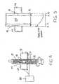
- FIG. 1shows a delivery device 10 which contains a supply of a curable composition 20.
- the composition 20is a curable biomaterial or bio-compatible material, such as bone cement.
- the composition 20is curable, meaning that it changes operating state or physical properties over time.
- a typical bone cementsuch as polymethylmethacrylate, polymerizes over time so that the viscosity or flowability of the composition gradually changes until the composition is fully hardened.
- the delivery device 10may be any container suitable for containing a bone cement mixture as it cures. More particularly, the container is suitable for delivering the composition to a surgical site, such as into the intramedullary canal of a bone in preparation for receiving the stem of a prosthesis. In accordance with the present invention, the delivery device must permit passage of acoustic signals, or more specifically ultrasonic signals, and should have stable acoustic properties. Most preferably, the delivery device is a syringe that includes a barrel 12 within which the composition 20 is contained. While the barrel 12 is cylindrical, for purposes of understanding the present invention it is presumed that the barrel includes a proximal portion 14 and a distal portion 16 that is generally diametrically opposite the proximal portion. The syringe barrel is typically formed of a plastic material that has known physical properties for transmission of acoustic signals that can be readily quantified for use with the present invention.
- the assembly 25includes a body 27 that is configured to be held flush with the barrel 12 of the composition delivery device.
- one surface 28 of the body 27can be curved to match the curvature of the barrel at the proximal portion 14.
- the delivery devicecan be modified so that parallel and opposing flat surfaces are created across the diameter of the body.
- the radius of the barrel 12 of the delivery device 10is large enough with respect to the size of the ultrasound transducer, a flat-faced transducer may be used without degradation in performance.
- the bodycan be provided with some means to hold the body on the barrel.
- the curved surface 28 of the bodycan be provided with a removable adhesive.
- a clip or strap(not shown) can be associated with the body 27 and configured to engage the barrel to hold the surface 28 in flush contact with the barrel.
- An acoustic couplantsuch as a gelatinous material, may be necessary to ensure proper acoustic signal propagation from the ultrasound transducer into the delivery device-admixture composite and proper reflection back to the transducer.
- a gelatinous material(not shown) is preferably interposed between the body 27 of the assembly 25 and the barrel 12.
- the assembly 25relies upon sensing a reflected acoustic signal.
- the body 27carries an acoustic emitter 30 and an acoustic sensor 32.
- the emitter and sensorare adapted for ultrasonic signals, such as in the range of 100kHz to 20 MHz.
- the emitter 30is an ultrasonic transducer of known design, such as a piezo-electric transducer, capable of generating an ultrasonic signal of a fixed or variable frequency.
- the sensor 32is also of conventional design, such as a sensing transducer that is tuned to a specific frequency or frequency band. Alternatively, the same emitter can perform transmission and sensing functions through the use of known switching circuitry.
- the ultrasonic emitter and sensor for use with the present inventioncan be of the kind which is disclosed in US-6491635 .
- the disclosed bone densitometerincludes transmitting and receiving transducer arrays and associated circuitry to excite or sample a particular transducer in the array.
- other ultrasonic measurement systemsare contemplated that can meet the physical requirements of the system of the present invention.
- the emitter and sensorare sized according to the size of the delivery device, and their relative spacing by the amplitude of the acoustic signal. Preferably, the emitter and receiver are immediately adjacent so that the reflected acoustic signal will strike the sensor 32.
- the body 27occupies an area of about 6.45 cm 2 (1.0 inch 2 ).
- the apparatus 25relies upon an ultrasonic signal emitted by transducer 30 into the syringe barrel 12 and bone cement composition 20 within. It is known that a portion of an acoustic or ultrasonic signal will reflect at the interface or boundary between dissimilar materials.
- four such interfacesexist, as depicted in FIG. 2 , including: apparatus-proximal portion interface 50; proximal portion - curable composition interface 52, composition - distal portion interface 54; and distal portion - air interface 56. (It can be noted that this last interface 56 can be augmented by a reflective plate mounted to the distal portion 16).
- Each interfacewill produce a reflected signal from the basic signal transmitted by the emitter 30.
- a representation of the reflected signal as a function of time and interface locationis provided in FIG. 2 . It can be seen that the intensity or amplitude of the reflected signal decreases at each interface and that the time for the reflected signal to be received by the sensor 32 increases, as expected.
- the reflected signal received by the sensor 32provides a measure of the operating condition of the composition 20 between the proximal and distal portions 14, 16. It is known that the acoustic transmission properties of the curable composition 20 will change over time. This change in transmission properties can be the result of changes in the numbers of scattering particles, which will affect the amplitude of the acoustic signal. Sensed changes in the transmission/reflection of the acoustic signal can be correlated to changes in acoustic properties of the composition, which in turn can be correlated to a current operating condition of the composition.
- the apparatus 25is electrically coupled by wiring 34 to a processor 36.
- This processorincludes an amplifier 38 that electrically activates the ultrasonic transducer 28 and a sampling circuit 40 that samples an electrical signal generated by the sensor 32 in response to a reflected acoustic signal.
- the sampling circuitcan include an A/D converter to provide a digital signal that can be more readily processed.
- a microprocessor and/or digital signal processor 42receives the digital signal from the sampling circuit 40 and generates an output for a display 44 indicative of a sensed condition of the composition.
- the microprocessor 42is calibrated to evaluate the output of the sensor 32 as it relates to the degree of cure, for instance, of the composition.
- the sensor 32receives reflected signals from each of the interfaces 50-56. Since the acoustic properties of the barrel 12 of the syringe 10 do not change, any change in the reflected acoustic signal can be directly attributed to changes in the physical properties of the composition.
- the processor 36can be calibrated to evaluate the second and third reflected signals from the interfaces 52 and 54, and more specifically the time difference between these two signals.
- the difference between the times t 3 and t 2is directly related the speed of sound through the composition 20.
- the microprocessor 42can make this calculation each time the emitter 30 transmits an ultrasonic signal - i.e., for each chirp. This time differential can be compared to an empirically obtained differential value that corresponds to a preferred degree of cure, or preferred operating point of the composition 20.
- the difference between the times t 4 and t 1is directly related the speed of sound through the admixture-delivery device composite. As the acoustic properties of the delivery device are stable, the only change in this parameter will be due to changes in the admixture.
- the microprocessorcan be calibrated to evaluate the output of this calculation as described above.
- the microprocessor 42can generate a signal to the display 44.
- the display 44can constitute a visual indicator, such as an LED that illuminates when the appropriate operating point has been achieved.
- a series of LEDscan be provided that are illuminated at different stages of the composition operating state, in particular when the measured time correlates with empirical values corresponding to the different operating states of the composition.
- the indicatorcan be integrated into the apparatus 25 so that it is associated with or mounted on the container or delivery device 10, and therefore immediately at hand.
- An audible signalcan replace or augment the visual indicator.
- the processor 36can be configured at different degrees of sophistication.
- the processoractivates the emitter 30 at a pre-determined interval that is preferably, but not necessarily, greater than the greatest reflectance time t 4 , so that no intervening reflected signals from interfaces 50 or 52 will interfere with the signal reflected from the interface 54. This chirp interval will typically be measured in milliseconds.
- the processorwill include a switch that changes the mode of the emitter 30 from transmitter to receiver after a chirp signal has been sent, and from receiver to transmitter once the last reflected signal has been received at time t 4 .
- the processorcounts the signals and measures the time delay from the transmission of the basic ultrasonic signal.
- the processorcan measure the delay from receipt of the second reflected signal at time t 2 , or can continuously measure all of the time intervals t 1 -t 4 and then calculate the pertinent differential t 3 -t 2 , or t 4 -t 1 .
- the processor 36is configured to evaluate the amplitude, or ultimately the attenuation, of the signal reflected at any or all of the interfaces 52, 54 and 56. As depicted in the graph in FIG. 2 , the amplitude of the reflected signal decreases at each of the interfaces. Again, since the material of the syringe barrel is known and unchanging, the attenuation at the first and last reflection interfaces is also known and quantifiable. However, amplitude of the reflected signal at the interfaces 52 and 54 depend upon the properties of the composition 20. Changes in the amplitude of the reflected signal from either of these interfaces can be compared to empirically derived data based on reflective attenuation for different composition operating conditions or cure amounts.
- the microprocessor 42can store this empirically derived data and compare the real time amplitude of a selected reflected signal. Alternatively, changes in all of the reflected signals can be analysed by the microprocessor and averaged or normalized for comparison to a pre-determined value indicative of the optimum operating condition of the composition.
- the delivery devicemay also contain an inner barrel that may be used for mixing.
- an inner barrelthat may be used for mixing.
- the systemrelies upon the propagation of the ultrasonic signal through the composition.
- an emitter 60is coupled to the proximal portion 14 of the syringe barrel 12 and a sensor 70 is coupled to the distal portion 16.
- the two transducers 60, 70can be coupled to the delivery device in any manner sufficient to removably support them on the delivery device.
- the two componentscan utilize the removable adhesive, clip or strap approaches described above.
- the emitter and receivercan be piezo-electric transducers or other devices capable of sending and receiving ultrasonic signals.
- the emitter 60transmits an ultrasonic signal toward the sensor 70 and through the syringe barrel 12 and composition 20.
- the transmission properties of the material forming the barrelare fixed and known, while the propagation properties of the composition are variable. Nominally, the acoustic signal is attenuated as it travels through the three layers, although most of the attenuation occurs as the ultrasonic signal propagates through the composition 20, is shown in the graph in FIG. 5 .
- Each transmitted ultrasonic signal or chirp delivered by the emitter 60will attenuate generally in accordance with this curve and will travel from the emitter 60 to the sensor transducer 70. The amount of attenuation and the propagation time will vary as the physical properties of the composition changes.
- a processor 80controls the activation of the emitter and the evaluation of the signal received from sensor transducer 70.
- the processor 80controls the time interval at which the ultrasonic chirp is transmitted and measures the time delay before the sensor 70 acknowledges that the propagated signal has been received. If the transmission time is used as the quantitative measure of the change in operating condition of the composition, then the amplitude or amount of attenuation of the signal need not be evaluated. In this instance, an A/D converter is not necessary.
- signal attenuationis used as the quantitative measure, then the sensor signal can be fed through an A/D converter to provide a digital representation of the amplitude of the propagated signal.
- the absolute amplitude or the incremental change in amplitude, or any order derivative of the amplitude signal with respect to timecan be used as the trigger point, depending upon the nature of the empirical data used for comparison.
- the processor 36, 80will compare data acquired in real-time as the composition is curing with stored data indicative of the operating points of the curable composition.
- bone cementsbegin polymerizing or curing as soon as the liquid and powder constituents are mixed.
- the working time -i.e, the time during which the composition can be applied in the surgical setting - commences at the end of the dough time and continues until the end of working time,
- the stored datawill optimally include data for both operating points.
- other operating points, such as setting timecan also be maintained by the processors 36, 80.
- the processormay contain complete time-dependent data sets for a number of bone cement samples, and that it will contain an algorithm for comparing the current sample to those samples stored so that the end of working time can be predicted (or otherwise estimated) in real time as the bone cement is used.
- a predicted amount of time remaining until the working time of the composition is reachedcan be generated based on such comparison.
- a visual indication of such predicted amount of time remainingcan then be visually displayed on a display device 71 (see FIG. 3 ).
- the predicted amount of time remaining until the working time of the composition is reachedmay be audibly generated via a speaker 72 (see FIG. 3 ).
- One benefit of this inventionis that it can be used to identify the dough time, end of working time, and setting time, and then to relay this information to the orthopaedic surgeon during surgery using a display.
- An array of indicatorscan be used to indicate the current operating condition of the bone cement. For instance, a differently coloured LED can be activated by the processors at the dough time, end of working time and setting time so that the surgeon has an immediate indication of the bone cement condition.
- the stored dataincludes only the pre-determined operating point values.
- the time delay value corresponding to the dough time for the compositionis stored and compared against the real-time delay values calculated by the processor 80.
- a table look-up or an algorithmcan be utilized to ascertain a degree of cure throughout the entire curing process.
- an ultrasonic signalis transmitted at pre-determined intervals on the order of milliseconds in length. Thus, for a one minute dough time, several hundreds of measurements will be made. Each measurement can be compared to the table look-up to ascertain the degree of completion of the dough time, and can even determine an increase or decrease in curing rate.
- the various data points indicative of the operating points or degree of curing of a particular compositionwill be derived empirically. For instance, test samples of a PMMA bone cement are subjected to a conventional viscosity test, or qualitative testing for identification of the dough time, end of working time, and setting time at pre-determined intervals will be performed. The same sample is simultaneously subjected to testing in accordance with an embodiment of the present invention. The acoustic response value generated by the present invention is then correlated to the conventionally derived viscosity value or operating point if measured directly. Repeating this test at the pre-determined time intervals will map a particular result using the present invention to a known operating point of the composition. These experiments will need to be performed for a variety of bone cements both with and without antibiotics, and in variable environmental conditions.
- compositionsmay respond more effectively to acoustic signals in a certain frequency range.
- the present inventioncontemplates that the transducer components 25, 60 and 70 will be "universal", meaning that they can be used on a wide array of delivery devices.
- the transducer(s)can be mounted to the delivery devices in the manner described above, or can be integrated into a fixture that supports the delivery device and holds it in proper relationship to the transducer(s).
- the processors 36, 80can be integrated with the transducer(s) but are preferably separate from the emitter and sensor devices.
- the processoritself can be formed as an integrated circuit or chip that is connected to the transducer(s) during use.
- the chipcan be provided with the curable composition, with the necessary pre-determined data points "hard-wired" into the chip. Alternatively, the chip can constitute a data chip that is connected to a separate stand-alone processor.
- the present inventioncontemplates, in effect, measuring the acoustic properties, and changes thereof, of the curable material and equating those changes to a known operating condition or state of cure of the material.
- the absolute magnitude of an acoustic propertyis measured.
- the magnitudeincludes the amplitude or intensity of the acoustic signal or wave.
- the absolute magnitude of the signal attentuationcan be compared at different times to determine the operating state of the composition.
- the changes in signal attenuationcan be calculated and assessed in relation to the degree of cure of the material.
- the first derivative of the signal attenuation through the composition as a function of timecan be calculated and compared to empirically derived data to determine the composition operating state.
Landscapes
- Health & Medical Sciences (AREA)
- Life Sciences & Earth Sciences (AREA)
- General Health & Medical Sciences (AREA)
- Physics & Mathematics (AREA)
- Immunology (AREA)
- Engineering & Computer Science (AREA)
- Surgery (AREA)
- Pathology (AREA)
- General Physics & Mathematics (AREA)
- Biochemistry (AREA)
- Analytical Chemistry (AREA)
- Orthopedic Medicine & Surgery (AREA)
- Chemical & Material Sciences (AREA)
- Heart & Thoracic Surgery (AREA)
- Biomedical Technology (AREA)
- Veterinary Medicine (AREA)
- Public Health (AREA)
- Animal Behavior & Ethology (AREA)
- Molecular Biology (AREA)
- Medical Informatics (AREA)
- Signal Processing (AREA)
- Nuclear Medicine, Radiotherapy & Molecular Imaging (AREA)
- Acoustics & Sound (AREA)
- Investigating Or Analyzing Materials By The Use Of Ultrasonic Waves (AREA)
- Apparatus For Radiation Diagnosis (AREA)
- Measuring And Recording Apparatus For Diagnosis (AREA)
- Ultra Sonic Daignosis Equipment (AREA)
- Prostheses (AREA)
Abstract
Description
- The present invention relates to the preparation of orthopaedic mixtures and compounds, such as bone cement. More specifically, the invention concerns systems and methods for identifying the operating state of these compounds, such as the degree of cure of bone cement.
- It is necessary in many orthopaedic surgical procedures to employ a cement or grouting type agent, such as for attaching artificial joint implants to bone, repairing or forming joints in bones, or other forms of orthopaedic work. The type of cement used typically depends upon many factors, including the type of implant, the manner of application, the amount of working time required, etc. While many types of bone cement are available, most of the cements used for orthopaedic purposes include a self-curing resin formed from the blending of a wide variety of liquid monomers or co-monomers with powdered polymers or copolymers to form a viscous admixture to be used as the grouting agent. Most bone cements are acrylate-based compositions formed of a liquid component and a powder component. A typical liquid component is a liquid mixture of methyl methacrylate monomer. The powder component generally consists of a methylmethacrylate-styrene copolymer. Curing of the liquid-powder composition occurs as the constituents polymerize and cross-link.
- The admixture of the powder and liquid components develops a quick setting material. As such, preparation of the cement usually occurs directly within the operating area just prior to use. In particular, a bone cement mixing apparatus is generally utilized to mix the powder and liquid components in the operating area. The resultant admixture is then removed from the mixing apparatus and placed in a cement delivery apparatus for subsequent use by the surgeon. Specifically, the bone cement must generally first be scooped or otherwise removed from the mixing apparatus and thereafter placed in a syringe-type delivery apparatus for use by the surgeon. In other cases, the bone cement components are mixed directly in the delivery apparatus, which eliminates the need to transfer the bone cement from a mixing apparatus to the syringe-type delivery system.
- Bone cements typically have setting times between 6½ to 15 minutes. Three operating points characterize the curing of bone cement. The dough time, distinguished qualitatively as the point in time where bone cement no longer sticks to latex gloves, is the first operating point. The dough time, which is measured relative to initial mixing, occurs after the mixing of the bone cement. The dough time is significant as it is identified as the start point of the working time of the admixture. The working time encompasses the amount of time during which the viscosity or flowability of the composition is sufficient to allow introduction of the composition into the surgical or implant site. The end of working time, distinguished qualitatively as the point in time where bone cement no longer sticks to itself, is the second operating point. The end of work time is relative to initial mixing and signifies that the working time has ended and the bone cement should no longer be used in the surgery. The third operating point is the setting time, which is the time relative to initial mixing at which the bone cement admixture hardens or sets sufficiently to hold the prosthesis within its implant site.
- Since the overall setting times for most orthopaedic compositions, such as bone cements, are short, it is important that the composition be introduced into the implant site as soon as practicable. For many compositions, the admixture must reach a certain level of cure to have the viscosity, flowability or malleability to allow the material to be properly introduced into the surgical site. For instance, many orthopaedic implants include a stem that is fixed within the intramedullary canal of a bone, such as the femur. As a precursor, bone cement is injected into the prepared intramedullary canal prior to introduction of the implant stem. Optimally, the bone cement flows into porous recesses of the bone to ensure a solid mechanical interlock with the implant. If the bone cement is administered before the appropriate degree of cure, the cement will be too fluid, which may make it difficult to properly administer. Moreover, if the bone cement is too fluid, it may overflow upon application or when the implant stem is introduced.
- On the other hand, if the cement has cured too much, it may be too viscous so that it does not fill the bone voids and interstices. This can result in a poor mechanical interlock or interface between implant and bone. Even if the composition is viscous enough for proper application, it may curein situ to a point that prevents proper positioning and alignment of the implant stem within the bone. An even greater degree of cure will render the bone cement too viscous to be usable.
- Bone cement failure is believed to be a primary mechanism for loosening of prosthetic joint components. It can be readily appreciated that it is very desirable to accurately determine the degree of cure or operating state of the composition in the surgical arena so that the composition can be applied at the optimum point in its curing cycle. One ASTM standard relies upon determining the resistance to a plunger pushed into a container of curable material. A similar approach is disclosed in
EP-A-995981 - In another approach, an electric current is passed through a bone cement sample. Variation in an electrical property of the bone cement, such as capacitance, is used to determine the amount of cure of the material, for example, as disclosed in
DE-A-10008481 . One drawback with this approach is that it is equipment intensive. Moreover, this approach requires the composition to not only have measurable electrical properties, but also that the electrical properties vary as a function of the cure of the material. US-3413595 discloses ultrasonic apparatus for checking processes in liquid media, which includes an emitter of an acoustic signal, a sensor for the signal after it has passed through the liquid media, and a processor by which the speed of the signal in the media can be calculated.US-4327587 discloses a method and apparatus for continuous measurement of changes in rheological properties of monomers during polymerisation wherein ultrasonic transducers are placed in intimate contact with the polymer in order to pass ultrasonic ocellations through it.- There is a need for a system and method for accurately determining the operating condition or degree of cure of a biological composition, such as bone cement. The need is also felt for such a system that can be used with the composition as it exists in the surgical setting. This need further extends to a reusable system that requires minimal or no redesign of current delivery systems.
- In order to meet these needs, the present invention contemplates a system and method that relies upon the acoustic properties of the biocompatible composition or admixture. More specifically, the invention resides in exposing the composition in a container, such as an application delivery system, to an ultrasonic signal. Changes in the acoustic properties of the composition can be correlated to changes in its degree of polymerization or cure. The acoustic properties can be based on reflectance and transmittance of the acoustic signal and involve measurement of the attenuation of the signal amplitude as well as any order derivatives as a function of time of this property. The property can be related either to the admixture alone or to the admixture-delivery system composite.
- Accordingly, in one aspect, the invention provides a method of determining the operating state of a curable bio-compatible composition comprising the steps of:
- providing a composition in a container having at least a portion that permits transmission of an acoustic signal therethrough;
- supporting an emitter externally to the container and adjacent to said portion of the container, said emitter configures to emit an acoustic signal;
- supporting a sensor externally to the container and adjacent to said portion of the container, said sensor configured to sense an acoustic signal received from within said container;
- directing an acoustic signal to the composition through the portion of the container;
- measuring the attenuation of the amplitude of the acoustic signal which has been transmitted through or reflected by the composition; and
- correlating the magnitude to an operating state of the composition.
- In another aspect, the invention provides a system for determining the operating state of a curable biocompatible composition comprising:
- a container for containing the curable composition, the container including at least a portion that permits transmission of an acoustic signal therethrough;
- an emitter supported externally to the container and adjacent to said portion of the container, said emitter configured to emit an acoustic signal;
- a sensor supported externally to the container and adjacent to said portion of the container, said sensor configured to sense an acoustic signal received from within said container; and
- a processor for determining from data from the sensor the attenuation of the amplitude of an acoustic signal which passes from the emitter into the container with the curable composition therein.
- In accordance with the invention, the admixture is prepared and stored in a delivery device that will be used to apply the admixture to the surgical site. The delivery device is formed of a standard material, such as polypropylene or glass, which permits passage of acoustic signals. An ultrasonic transducer is mounted to the wall of the delivery device. In one embodiment, the transducer includes a receiver array to receive reflected ultrasonic signals. It is known that the interface between dissimilar materials will produce a reflection of an acoustic signal. Thus, this embodiment contemplates reflected signals from the wall-composition interfaces adjacent the ultrasonic sensors (near wall reflectance) and on the delivery device wall opposite the transducer (far wall reflectance). This embodiment also contemplates reflected signals from the wall-air interface opposite the transducer (far air reflectance). As the composition cures, its physical properties change, which results in a change of reflectance at the wall-composition and wall-air interfaces. An empirical relationship between near wall, far wall, and far air reflectance values and the degree of cure of the composition can be derived and compared to the test values to provide a real-time determination of the operating point of the composition. This empirical relationship can be based on the change in the speed of sound, or some other measured or calculated parameter, through the material as a function of time.
- In another embodiment, the ultrasonic wave passes from the transducer, through a couplant, then through the delivery device wall and composition to a sensor mounted on the opposite wall of the delivery device. In this embodiment, the change in transmittance of the admixture or the admixture-delivery device composite is evaluated.
- Accordingly, the invention provides a system and method that provide an accurate real-time measurement of the degree of polymerization or cure of a bio-compatible composition, such as bone cement. The measurement can be obtained without disturbing the composition in its application apparatus.
- The technique of the invention allows the three key stages of cure of a bone cement - dough time, end of work time, and setting time - to be identified, so that this information can be provided to the orthopaedic surgeon using a simple display method during surgery. Such a display device may be affixed to the delivery system, may be integrated with already existing computer technologies, or may be a stand-alone display. It is contemplated that a simple red, yellow, green LED display will suffice to present the operating points of the bone cement to the surgeon. It is also contemplated that a prediction of the end of work time taking into consideration environmental variables, such as relative humidity and temperature, would be provided to the surgeon. Such a prediction can be based on laboratory data along with data measured from the display device. The device might present a countdown in some time unit to the surgeon after the dough time has been identified so that the surgeon has a real-time estimate of the end of work time during use of the bone cement. When the end of work time has been identified, it will be displayed to the surgeon so that the bone cement is not used outside of the working time. Such a display method will increase the utility of the contemplated system.
- Embodiments of the invention will now be described by way of example with reference to the accompanying drawings, in which:
FIG. 1 is a side perspective view of a delivery device carrying a curable composition with an ultrasonic transducer apparatus mounted thereto in accordance with one embodiment of the present invention.FIG. 2 is a partial cross-sectional view of the delivery device and transducer apparatus shown inFIG. 1 , with the reflective interfaces identified and with a sample graph of reflected energy as a function of time superimposed thereon. (Note that the dashed lines inFIG. 2 indicate corresponding interfaces of reflected signals.)FIG. 3 is a schematic representation of the transducer apparatus and associated processor.FIG. 4 is a side perspective view of a delivery device carrying a curable composition with an ultrasonic transducer and receiver apparatus mounted thereto in accordance with a further embodiment of the present invention.FIG. 5 is a partial cross-sectional view of the delivery device and transducer apparatus shown inFIG. 4 , with the transmission interfaces identified and with a sample attenuation graph as a function of distance superimposed thereon. (Note that the dashed lines inFIG. 5 indicate corresponding interfaces of reflected signals.)- Referring to the drawings,
FIG. 1 shows adelivery device 10 which contains a supply of acurable composition 20. In the preferred embodiment of the invention, thecomposition 20 is a curable biomaterial or bio-compatible material, such as bone cement. Thecomposition 20 is curable, meaning that it changes operating state or physical properties over time. For instance, a typical bone cement, such as polymethylmethacrylate, polymerizes over time so that the viscosity or flowability of the composition gradually changes until the composition is fully hardened. - The
delivery device 10 may be any container suitable for containing a bone cement mixture as it cures. More particularly, the container is suitable for delivering the composition to a surgical site, such as into the intramedullary canal of a bone in preparation for receiving the stem of a prosthesis. In accordance with the present invention, the delivery device must permit passage of acoustic signals, or more specifically ultrasonic signals, and should have stable acoustic properties. Most preferably, the delivery device is a syringe that includes abarrel 12 within which thecomposition 20 is contained. While thebarrel 12 is cylindrical, for purposes of understanding the present invention it is presumed that the barrel includes aproximal portion 14 and adistal portion 16 that is generally diametrically opposite the proximal portion. The syringe barrel is typically formed of a plastic material that has known physical properties for transmission of acoustic signals that can be readily quantified for use with the present invention. - An acoustic generator and
sensor assembly 25 is associated with thedelivery device 10. As shown inFIG. 3 , theassembly 25 includes abody 27 that is configured to be held flush with thebarrel 12 of the composition delivery device. Thus, onesurface 28 of thebody 27 can be curved to match the curvature of the barrel at theproximal portion 14. Additionally, if slight modification of the delivery device is advantageous and minimizes the system design, the delivery device can be modified so that parallel and opposing flat surfaces are created across the diameter of the body. Also, if the radius of thebarrel 12 of thedelivery device 10 is large enough with respect to the size of the ultrasound transducer, a flat-faced transducer may be used without degradation in performance. The body can be provided with some means to hold the body on the barrel. For instance, thecurved surface 28 of the body can be provided with a removable adhesive. Alternatively, a clip or strap (not shown) can be associated with thebody 27 and configured to engage the barrel to hold thesurface 28 in flush contact with the barrel. An acoustic couplant, such as a gelatinous material, may be necessary to ensure proper acoustic signal propagation from the ultrasound transducer into the delivery device-admixture composite and proper reflection back to the transducer. Thus, a gelatinous material (not shown) is preferably interposed between thebody 27 of theassembly 25 and thebarrel 12. - The
assembly 25 relies upon sensing a reflected acoustic signal. Thus, thebody 27 carries anacoustic emitter 30 and anacoustic sensor 32. Most preferably, the emitter and sensor are adapted for ultrasonic signals, such as in the range of 100kHz to 20 MHz. Theemitter 30 is an ultrasonic transducer of known design, such as a piezo-electric transducer, capable of generating an ultrasonic signal of a fixed or variable frequency. Thesensor 32 is also of conventional design, such as a sensing transducer that is tuned to a specific frequency or frequency band. Alternatively, the same emitter can perform transmission and sensing functions through the use of known switching circuitry. For purposes of illustration, the ultrasonic emitter and sensor for use with the present invention can be of the kind which is disclosed inUS-6491635 . The disclosed bone densitometer includes transmitting and receiving transducer arrays and associated circuitry to excite or sample a particular transducer in the array. Of course, other ultrasonic measurement systems are contemplated that can meet the physical requirements of the system of the present invention. - The emitter and sensor are sized according to the size of the delivery device, and their relative spacing by the amplitude of the acoustic signal. Preferably, the emitter and receiver are immediately adjacent so that the reflected acoustic signal will strike the
sensor 32. By way of non-limiting example, for use with a typicalsyringe delivery device 10, thebody 27 occupies an area of about 6.45 cm2 (1.0 inch2). - In accordance with the embodiment of
FIG. 1 , theapparatus 25 relies upon an ultrasonic signal emitted bytransducer 30 into thesyringe barrel 12 andbone cement composition 20 within. It is known that a portion of an acoustic or ultrasonic signal will reflect at the interface or boundary between dissimilar materials. In the context of the present invention, four such interfaces exist, as depicted inFIG. 2 , including: apparatus-proximal portion interface 50; proximal portion -curable composition interface 52, composition - distal portion interface 54; and distal portion -air interface 56. (It can be noted that thislast interface 56 can be augmented by a reflective plate mounted to the distal portion 16). - Each interface will produce a reflected signal from the basic signal transmitted by the
emitter 30. A representation of the reflected signal as a function of time and interface location is provided inFIG. 2 . It can be seen that the intensity or amplitude of the reflected signal decreases at each interface and that the time for the reflected signal to be received by thesensor 32 increases, as expected. - The reflected signal received by the
sensor 32 provides a measure of the operating condition of thecomposition 20 between the proximal anddistal portions curable composition 20 will change over time. This change in transmission properties can be the result of changes in the numbers of scattering particles, which will affect the amplitude of the acoustic signal. Sensed changes in the transmission/reflection of the acoustic signal can be correlated to changes in acoustic properties of the composition, which in turn can be correlated to a current operating condition of the composition. - In this embodiment of the invention, the
apparatus 25 is electrically coupled by wiring 34 to aprocessor 36. This processor includes anamplifier 38 that electrically activates theultrasonic transducer 28 and asampling circuit 40 that samples an electrical signal generated by thesensor 32 in response to a reflected acoustic signal. The sampling circuit can include an A/D converter to provide a digital signal that can be more readily processed. A microprocessor and/ordigital signal processor 42 receives the digital signal from thesampling circuit 40 and generates an output for adisplay 44 indicative of a sensed condition of the composition. - The
microprocessor 42 is calibrated to evaluate the output of thesensor 32 as it relates to the degree of cure, for instance, of the composition. In accordance with this embodiment, thesensor 32 receives reflected signals from each of the interfaces 50-56. Since the acoustic properties of thebarrel 12 of thesyringe 10 do not change, any change in the reflected acoustic signal can be directly attributed to changes in the physical properties of the composition. In one specific feature of this embodiment, theprocessor 36 can be calibrated to evaluate the second and third reflected signals from theinterfaces 52 and 54, and more specifically the time difference between these two signals. Since the distance between theinterfaces 52 and 54 is known (i.e., the diameter of the syringe barrel), the difference between the times t3 and t2 is directly related the speed of sound through thecomposition 20. Themicroprocessor 42 can make this calculation each time theemitter 30 transmits an ultrasonic signal - i.e., for each chirp. This time differential can be compared to an empirically obtained differential value that corresponds to a preferred degree of cure, or preferred operating point of thecomposition 20. Alternatively, the difference between the times t4 and t1 is directly related the speed of sound through the admixture-delivery device composite. As the acoustic properties of the delivery device are stable, the only change in this parameter will be due to changes in the admixture. The microprocessor can be calibrated to evaluate the output of this calculation as described above. - When the measured time differential matches or falls within a pre-determined range of the empirical value, the
microprocessor 42 can generate a signal to thedisplay 44. Thedisplay 44 can constitute a visual indicator, such as an LED that illuminates when the appropriate operating point has been achieved. A series of LEDs can be provided that are illuminated at different stages of the composition operating state, in particular when the measured time correlates with empirical values corresponding to the different operating states of the composition. The indicator can be integrated into theapparatus 25 so that it is associated with or mounted on the container ordelivery device 10, and therefore immediately at hand. An audible signal can replace or augment the visual indicator. - The
processor 36 can be configured at different degrees of sophistication. In its simplest form, the processor activates theemitter 30 at a pre-determined interval that is preferably, but not necessarily, greater than the greatest reflectance time t4, so that no intervening reflected signals frominterfaces emitter 30 from transmitter to receiver after a chirp signal has been sent, and from receiver to transmitter once the last reflected signal has been received at time t4. As the reflected signals are received, the processor counts the signals and measures the time delay from the transmission of the basic ultrasonic signal. The processor can measure the delay from receipt of the second reflected signal at time t2, or can continuously measure all of the time intervals t1-t4 and then calculate the pertinent differential t3-t2, or t4-t1. - In a more sophisticated system, the
processor 36 is configured to evaluate the amplitude, or ultimately the attenuation, of the signal reflected at any or all of theinterfaces FIG. 2 , the amplitude of the reflected signal decreases at each of the interfaces. Again, since the material of the syringe barrel is known and unchanging, the attenuation at the first and last reflection interfaces is also known and quantifiable. However, amplitude of the reflected signal at theinterfaces 52 and 54 depend upon the properties of thecomposition 20. Changes in the amplitude of the reflected signal from either of these interfaces can be compared to empirically derived data based on reflective attenuation for different composition operating conditions or cure amounts. Themicroprocessor 42 can store this empirically derived data and compare the real time amplitude of a selected reflected signal. Alternatively, changes in all of the reflected signals can be analysed by the microprocessor and averaged or normalized for comparison to a pre-determined value indicative of the optimum operating condition of the composition. - In a very similar embodiment, the delivery device may also contain an inner barrel that may be used for mixing. The principles of the described embodiment are unaffected, although the reflecting interfaces will change and data analysis must be adjusted accordingly.
- In an alternative embodiment, the system relies upon the propagation of the ultrasonic signal through the composition. Thus, as depicted in
FIG. 4 , anemitter 60 is coupled to theproximal portion 14 of thesyringe barrel 12 and asensor 70 is coupled to thedistal portion 16. The twotransducers - In accordance with this embodiment, the
emitter 60 transmits an ultrasonic signal toward thesensor 70 and through thesyringe barrel 12 andcomposition 20. The transmission properties of the material forming the barrel are fixed and known, while the propagation properties of the composition are variable. Nominally, the acoustic signal is attenuated as it travels through the three layers, although most of the attenuation occurs as the ultrasonic signal propagates through thecomposition 20, is shown in the graph inFIG. 5 . Each transmitted ultrasonic signal or chirp delivered by theemitter 60 will attenuate generally in accordance with this curve and will travel from theemitter 60 to thesensor transducer 70. The amount of attenuation and the propagation time will vary as the physical properties of the composition changes. - A
processor 80, similar in construction to theprocessor 36, controls the activation of the emitter and the evaluation of the signal received fromsensor transducer 70. Thus, theprocessor 80 controls the time interval at which the ultrasonic chirp is transmitted and measures the time delay before thesensor 70 acknowledges that the propagated signal has been received. If the transmission time is used as the quantitative measure of the change in operating condition of the composition, then the amplitude or amount of attenuation of the signal need not be evaluated. In this instance, an A/D converter is not necessary. On the other hand, if signal attenuation is used as the quantitative measure, then the sensor signal can be fed through an A/D converter to provide a digital representation of the amplitude of the propagated signal. The absolute amplitude or the incremental change in amplitude, or any order derivative of the amplitude signal with respect to time can be used as the trigger point, depending upon the nature of the empirical data used for comparison. - With either of the illustrated embodiments, the
processor processors FIG. 3 ). Alternatively (or additionally), the predicted amount of time remaining until the working time of the composition is reached may be audibly generated via a speaker 72 (seeFIG. 3 ). - One benefit of this invention is that it can be used to identify the dough time, end of working time, and setting time, and then to relay this information to the orthopaedic surgeon during surgery using a display. An array of indicators can be used to indicate the current operating condition of the bone cement. For instance, a differently coloured LED can be activated by the processors at the dough time, end of working time and setting time so that the surgeon has an immediate indication of the bone cement condition.
- In certain specific embodiments, the stored data includes only the pre-determined operating point values. In other words, if a transmission system is used, as shown in
FIG. 4 , the time delay value corresponding to the dough time for the composition is stored and compared against the real-time delay values calculated by theprocessor 80. Alternatively, a table look-up or an algorithm can be utilized to ascertain a degree of cure throughout the entire curing process. In accordance with the illustrated embodiments, an ultrasonic signal is transmitted at pre-determined intervals on the order of milliseconds in length. Thus, for a one minute dough time, several hundreds of measurements will be made. Each measurement can be compared to the table look-up to ascertain the degree of completion of the dough time, and can even determine an increase or decrease in curing rate. - It is contemplated that the various data points indicative of the operating points or degree of curing of a particular composition will be derived empirically. For instance, test samples of a PMMA bone cement are subjected to a conventional viscosity test, or qualitative testing for identification of the dough time, end of working time, and setting time at pre-determined intervals will be performed. The same sample is simultaneously subjected to testing in accordance with an embodiment of the present invention. The acoustic response value generated by the present invention is then correlated to the conventionally derived viscosity value or operating point if measured directly. Repeating this test at the pre-determined time intervals will map a particular result using the present invention to a known operating point of the composition. These experiments will need to be performed for a variety of bone cements both with and without antibiotics, and in variable environmental conditions.
- It is further contemplated that different materials may require different evaluation protocols using the systems and methods of the present invention. For instance, certain compositions may respond more effectively to acoustic signals in a certain frequency range. In other cases, it may be necessary to subject the composition to ultrasonic signals at different frequencies throughout the evaluation process. Applying an ultrasonic signal across a frequency spectrum can be used to increase the accuracy of the operating point evaluation. Additionally, it may be advantageous to measure or calculate one acoustically-dependent parameter for a given bone cement, and an entirely different parameter for another bone cement.
- The present invention contemplates that the
transducer components processors - The present invention contemplates, in effect, measuring the acoustic properties, and changes thereof, of the curable material and equating those changes to a known operating condition or state of cure of the material. In one embodiment, the absolute magnitude of an acoustic property is measured. In the illustrated embodiments above, the magnitude includes the amplitude or intensity of the acoustic signal or wave.
- In accordance with one embodiment of the invention, the absolute magnitude of the signal attentuation can be compared at different times to determine the operating state of the composition. Alternatively, the changes in signal attenuation can be calculated and assessed in relation to the degree of cure of the material. For example, the first derivative of the signal attenuation through the composition as a function of time can be calculated and compared to empirically derived data to determine the composition operating state.
Claims (16)
- A method of determining the operating state of a curable bio-compatible composition comprising the steps of:providing a composition in a container (10) having at least a portion that permits transmission of an acoustic signal therethrough;supporting an emitter (30) adjacent said portion of the container, said emitter configured to emit an acoustic signal;supporting a sensor (32) adjacent said portion of the container, said sensor configured to sense an acoustic signal received from within said container;directing an acoustic signal to the composition (20) through the portion of the container;measuring the attenuation of the amplitude of the acoustic signal which has been transmitted through or reflected by the composition; andcorrelating the magnitude to an operating state of the composition; and,characterised in that the emitter and sensor are supported externally to the container.
- The method of claim 1, wherein the operating state is time dependent and the measuring and correlating steps occur at period time intervals.
- The method of claim 1, further comprising the step of providing an indication when the attenuation of the amplitude of the signal correlates to a pre-determined operating state of the composition.
- The method of claim 3, in which the operating state of the curable composition includes dough time, end of working time and setting time, and wherein the step of providing an indication includes providing an indication at the end of the dough time.
- The method of claim 4, wherein the step of providing an indication includes providing an indication at the end of working time.
- The method of claim 3, wherein the indication is a visual indicator light.
- The method of claim 1, wherein the step of measuring the magnitude includes measuring the amplitude of the reflected component.
- The method of claim 1, wherein the container (10) is a delivery device for delivery of the curable composition to a site in the body.
- A system for determining the operating state of a curable biocompatible composition comprising:a container (10) for containing the curable composition, the container including at least a portion that permits transmission of an acoustic signal therethrough;an emitter (30) supported adjacent said portion of the container, said emitter configured to emit an acoustic signal;a sensor (32) supported adjacent said portion of the container, said sensor configured to sense an acoustic signal received from within said container; anda processor (36) for determining from data from the sensor the attenuation of the amplitude of an acoustic signal which passes from the emitter into the container with the curable composition therein; andcharacterised in that the emitter and sensor are supported externally to the container.
- The system of claim 9, wherein said emitter (30) and said sensor (32) are acoustic transducers.
- The system of claim 9, wherein said processor (36) is operable to activate said emitter (30) at pre-determined time intervals.
- The system of claim 9, wherein said sensor (32) is supported on said container (10) to receive a reflected component of said acoustic signal generated by said emitter (30).
- The system of claim 9, wherein said sensor (32) is supported on said container (10) to receive a transmitted component of said acoustic signal generated by said emitter (30).
- The system of claim 9, further comprising a display (44) activated by said processor (36) in response to the sensed acoustic signal.
- The system of claim 9, wherein said processor (36) is operable to compare the amplitude of an acoustic signal to a pre-determined value indicative of a pre-determined operating state of the composition.
- The system of claim 15, in which the operating state of the curable composition includes dough time, end of working time and setting time, and wherein said pre-determined value corresponds to the end of the dough time.
Applications Claiming Priority (1)
| Application Number | Priority Date | Filing Date | Title |
|---|---|---|---|
| US10/881,802US7618820B2 (en) | 2004-06-30 | 2004-06-30 | System and method for determining the operating state of orthopaedic admixtures |
Publications (2)
| Publication Number | Publication Date |
|---|---|
| EP1611873A1 EP1611873A1 (en) | 2006-01-04 |
| EP1611873B1true EP1611873B1 (en) | 2008-04-02 |
Family
ID=34941630
Family Applications (1)
| Application Number | Title | Priority Date | Filing Date |
|---|---|---|---|
| EP05253568AExpired - LifetimeEP1611873B1 (en) | 2004-06-30 | 2005-06-09 | System and method for determining the operating state of orthopaedic admixtures |
Country Status (5)
| Country | Link |
|---|---|
| US (2) | US7618820B2 (en) |
| EP (1) | EP1611873B1 (en) |
| AT (1) | ATE390901T1 (en) |
| AU (1) | AU2005202467B2 (en) |
| DE (1) | DE602005005740T2 (en) |
Families Citing this family (18)
| Publication number | Priority date | Publication date | Assignee | Title |
|---|---|---|---|---|
| US7618820B2 (en)* | 2004-06-30 | 2009-11-17 | Depuy Products, Inc. | System and method for determining the operating state of orthopaedic admixtures |
| GB0506186D0 (en)* | 2005-03-29 | 2005-05-04 | Univ Belfast | Apparatus and method |
| GB0510899D0 (en)* | 2005-05-28 | 2005-07-06 | Depuy Int Ltd | Apparatus for monitoring the cure of a bone cement material |
| US8562620B2 (en)* | 2008-04-21 | 2013-10-22 | Dfine, Inc. | Bone treatment systems |
| US8777479B2 (en) | 2008-10-13 | 2014-07-15 | Dfine, Inc. | System for use in bone cement preparation and delivery |
| US8540723B2 (en)* | 2009-04-14 | 2013-09-24 | Dfine, Inc. | Medical system and method of use |
| US8057090B1 (en)* | 2005-08-31 | 2011-11-15 | Subrata Saha | Automated bone cement mixer |
| US8574237B2 (en)* | 2005-12-30 | 2013-11-05 | DePuy Synthes Products, LLC | Method and apparatus for predicting the operating points of bone cement |
| US8394105B2 (en) | 2006-03-14 | 2013-03-12 | DePuy Synthes Products, LLC | Apparatus for dispensing bone cement |
| EP2140255A4 (en) | 2007-03-30 | 2014-04-23 | Commercialisation Des Produits De La Rech Appliquee Socpra Sciences Et Genie S E C Soc D | Method and apparatus for monitoring and/or controlling the curing of cements used in medical procedures |
| WO2008137428A2 (en) | 2007-04-30 | 2008-11-13 | Dfine, Inc. | Bone treatment systems and methods |
| WO2009021111A1 (en)* | 2007-08-08 | 2009-02-12 | Flodesign, Inc. | Flow improvements for delivery of biomaterials |
| US8231261B2 (en)* | 2008-02-05 | 2012-07-31 | Tyco Electronics Corporation | LED module and interconnection system |
| US9180416B2 (en) | 2008-04-21 | 2015-11-10 | Dfine, Inc. | System for use in bone cement preparation and delivery |
| US8142331B2 (en)* | 2010-03-23 | 2012-03-27 | Studio Allumage, Inc. | Vehicle engine shutdown prevention system |
| KR102563566B1 (en)* | 2016-12-19 | 2023-08-03 | 현대자동차주식회사 | METHOD FOR PREPARING ELECTRODE OF FUEL CELLs HAVING ENHANCED FREEZING RESISTANCE AND MANUFACTURING MEMBRANE ELECTRODE ASSEMBLY COMPRISING THE ELECTRODE |
| US12433655B2 (en)* | 2022-03-15 | 2025-10-07 | Orthopatent, Llc | Systems and methods for monitoring the cure of PMMA bone cement during surgery |
| CN114427986B (en)* | 2022-04-06 | 2022-07-01 | 南京庆瑞水泥有限公司 | Cement powder sampling and detecting system in concrete production |
Family Cites Families (104)
| Publication number | Priority date | Publication date | Assignee | Title |
|---|---|---|---|---|
| US3144966A (en)* | 1962-04-16 | 1964-08-18 | Semco Res Inc | Cartridge for mixing and dispensing sealant compound |
| US3413595A (en)* | 1966-10-27 | 1968-11-26 | Babikov Oleg Ivanovich | Ultrasonic apparatus for checking processes in liquid media |
| DE2236141B2 (en)* | 1972-07-22 | 1976-07-08 | Fa. Waldemar Link, 2000 Hamburg | PARTIAL DENTURE FOR A HUMAN ANKLE |
| US3816811A (en)* | 1973-01-12 | 1974-06-11 | R Cmelik | Fluid mixture analyzer using a capacitive probe and voltage divider |
| GB1446593A (en)* | 1973-01-12 | 1976-08-18 | Nat Res Dev | Endoprosthetic ankle joint devices |
| FR2220235A1 (en) | 1973-03-09 | 1974-10-04 | Anvar | Arthroplastic pin prosthesis - has front feet fitting in cavities in ankle bone and rear one in calcaneum |
| US3872519A (en)* | 1974-04-04 | 1975-03-25 | Nicholas J Giannestras | Total ankle prosthesis |
| US3886599A (en)* | 1974-07-25 | 1975-06-03 | Schlein Louis Charles | Surgically implantable total ankle prosthesis |
| US3889300A (en)* | 1974-08-28 | 1975-06-17 | Wright Mfg | Articulated two-part prosthesis replacing the ankle joint |
| US3975778A (en)* | 1975-07-14 | 1976-08-24 | Newton Iii St Elmo | Total ankle arthroplasty |
| US3987500A (en)* | 1976-01-28 | 1976-10-26 | Schlein Allen P | Surgically implantable total ankle prosthesis |
| US4021864A (en)* | 1976-04-14 | 1977-05-10 | The Regents Of The University Of California | Ankle prosthesis |
| US4069518A (en)* | 1976-08-31 | 1978-01-24 | Groth Jr Harry E | Total ankle prosthesis |
| GB1579773A (en) | 1977-07-18 | 1980-11-26 | Nat Res Dev | Endoprosthetic bone joint devices |
| US4470158A (en)* | 1978-03-10 | 1984-09-11 | Biomedical Engineering Corp. | Joint endoprosthesis |
| CS212352B1 (en)* | 1978-08-01 | 1982-03-26 | Jiri Docekal | Method of continuous measuring the changes of rheological properties of polymeres in the course of the polymerization process |
| US4338925A (en)* | 1979-12-20 | 1982-07-13 | Jo Miller | Pressure injection of bone cement apparatus and method |
| US4405249A (en)* | 1980-03-28 | 1983-09-20 | National Research Development Corporation | Dispensing apparatus and method |
| US4461407A (en)* | 1981-04-10 | 1984-07-24 | Danny Finnegan | Automatic pressure release mechanism for caulk gun |
| US4559810A (en)* | 1981-07-09 | 1985-12-24 | Applied Polymer Technology, Inc. | Method for determining resin viscosity with ultrasonic waves |
| US4450591A (en)* | 1981-12-10 | 1984-05-29 | Rappaport Mark J | Internal anti-proratory plug assembly and process of installing the same |
| FR2522823A1 (en)* | 1982-03-04 | 1983-09-09 | Oreal | CELL FOR MEASURING THE DIELECTRIC CONSTANT OF VISCOUS OR PASTY SUBSTANCES |
| US4467801A (en)* | 1983-03-09 | 1984-08-28 | Wright Manufacturing Company | Method and apparatus for shaping a proximal tibial surface |
| US4474177A (en)* | 1983-03-09 | 1984-10-02 | Wright Manufacturing Company | Method and apparatus for shaping a distal femoral surface |
| FR2543821A3 (en) | 1983-04-08 | 1984-10-12 | Viladot Perice Antonio | Endo-orthesis for flat feet |
| US4546767A (en)* | 1983-10-27 | 1985-10-15 | Smith Carl W | Cement injection device |
| DE3425566A1 (en)* | 1984-07-11 | 1986-01-16 | Draenert Klaus | DEVICE AND METHOD FOR MIXING AND APPLYING BONE CEMENT |
| FR2585130B1 (en)* | 1985-07-18 | 1987-10-09 | Solvay | APPARATUS FOR RAPID DETERMINATION OF RHEOLOGICAL PROPERTIES OF THERMOPLASTIC MATERIALS |
| EP0243681B1 (en)* | 1986-04-29 | 1990-06-13 | Siemens Aktiengesellschaft | Method and apparatus for registering the setting process of an inorganic aqueous binder system |
| US4755185A (en)* | 1987-01-27 | 1988-07-05 | Boehringer Mannheim Corporation | Prosthetic joint |
| CH669080GA3 (en)* | 1987-05-14 | 1989-02-28 | ||
| FR2615726A1 (en) | 1987-06-01 | 1988-12-02 | Landos Applic Orthopediques Fs | Prosthetic fixation element with anchoring stud |
| US4862384A (en)* | 1987-08-03 | 1989-08-29 | Rockwell International Corporation | Method of measuring the dynamic viscosity of a viscous fluid utilizing acoustic transducer |
| US4921415A (en) | 1987-11-27 | 1990-05-01 | General Electric Company | Cure monitoring apparatus having high temperature ultrasonic transducers |
| US6277076B1 (en)* | 1988-05-11 | 2001-08-21 | Lunar Corporation | Ultrasonic densitometer with pre-inflated fluid coupling membranes |
| US4968316A (en)* | 1988-12-12 | 1990-11-06 | Hergenroeder Patrick T | Arthroscopic ankle joint distraction method |
| US4921384A (en)* | 1989-06-07 | 1990-05-01 | Federal-Mogul Corporation | Swage fasteners with a high stand-off collar |
| SE8904036L (en) | 1989-11-29 | 1991-05-30 | Volvo Ab | LED PROTES, IN PARTICULAR, FOOT LEADER |
| US4994065A (en)* | 1990-05-18 | 1991-02-19 | Zimmer, Inc. | Apparatus for dispensing low viscosity semi-fluid material under pressure |
| US5187980A (en)* | 1990-05-31 | 1993-02-23 | The United States Of America As Represented By The United States Department Of Energy | Method and apparatus for acoustic plate mode liquid-solid phase transition detection |
| US5181636A (en)* | 1990-12-14 | 1993-01-26 | Milbar Corporation | Incremental dispensing device |
| FR2676917B1 (en) | 1991-05-29 | 1993-08-27 | Omci | ANKLE PROSTHESIS. |
| DE4120573A1 (en) | 1991-06-21 | 1992-12-24 | Siemens Ag | Determining solidification curve of resins and adhesives - using dielectric spectroscopy with sample under test between electrodes of capacitor subjected to AC electric field to measure frequency dependent AC resistance |
| FR2680968B1 (en) | 1991-09-05 | 1993-12-17 | Procom Sa | IMPLANT FOR SUB-ASTRAGALIAN ARTHRORISA. |
| US5431654A (en)* | 1991-09-30 | 1995-07-11 | Stryker Corporation | Bone cement injector |
| FR2684291B1 (en) | 1991-12-03 | 1994-03-04 | Ysebaert | ANKLE PROSTHESIS. |
| IT228979Y1 (en)* | 1992-03-09 | 1998-06-05 | Giannini Sandro | BIODEGRADABLE PROSTHESIS FOR READY FOOT CORRECTION. |
| US5326365A (en)* | 1992-04-10 | 1994-07-05 | Alvine Franklin G | Ankle implant |
| US5207712A (en)* | 1992-05-07 | 1993-05-04 | Michael Cohen | Absorbable joint implants for the lesser digits and metatarsal phalangeal joints in the surgical correction of the foot |
| US5342368A (en)* | 1992-07-08 | 1994-08-30 | Petersen Thomas D | Intramedullary universal proximal tibial resector guide |
| US5585733A (en)* | 1992-09-10 | 1996-12-17 | David Sarnoff Research Center | Capacitive sensor and method of measuring changes in capacitance |
| FR2700462B1 (en) | 1993-01-19 | 1995-04-21 | Medimplant | Apparatus for implanting a joint prosthesis. |
| JP2711802B2 (en)* | 1994-02-10 | 1998-02-10 | ナカシマプロペラ株式会社 | Intramedullary nail |
| US5501374A (en)* | 1994-06-17 | 1996-03-26 | Vital Products, Co. | Device for extruding high viscosity fluid having multiple modes of operation |
| US5556009A (en)* | 1994-07-18 | 1996-09-17 | Wagner Spray Tech Corporation | Adjustable constant pressure caulk gun |
| US5697932A (en)* | 1994-11-09 | 1997-12-16 | Osteonics Corp. | Bone graft delivery system and method |
| FR2730157B1 (en) | 1995-02-08 | 1997-07-04 | Bouvet Jean Claude | ANKLE PROSTHESIS |
| US5766259A (en)* | 1995-03-14 | 1998-06-16 | Sammarco; Giacomo J. | Total ankle prosthesis and method |
| WO1996042014A1 (en)* | 1995-06-08 | 1996-12-27 | Instituut Voor Milieu- En Agritechniek | Method for determining the degree of hardening of a material |
| US5893488A (en)* | 1995-09-18 | 1999-04-13 | Bristol-Myers Squibb Co. | Bone cement injector gun |
| US5638997A (en)* | 1995-09-18 | 1997-06-17 | Zimmer, Inc. | Bone cement injector gun |
| FR2747302B1 (en) | 1996-04-11 | 1998-09-11 | Tornier Sa | ANKLE PROSTHESIS |
| EP0821975A1 (en)* | 1996-07-31 | 1998-02-04 | Novartis AG (Novartis SA) (Novartis Inc.) | Dosing device for fluids |
| FR2759900B1 (en) | 1997-02-26 | 1999-06-11 | Sem Sa | SYSTEM FOR REPLACING THE ANKLE JOINT |
| FR2760354B1 (en) | 1997-03-10 | 1999-07-02 | Tornier Sa | PARTIAL ANKLE PROSTHESIS |
| FR2760353B1 (en)* | 1997-03-10 | 1999-07-02 | Tornier Sa | ANKLE PROSTHESIS |
| US5829875A (en)* | 1997-04-02 | 1998-11-03 | Simpson Strong-Tie Co., Inc. | Combined barrier and mixer assembly for a cylindrical container |
| US6227040B1 (en)* | 1998-02-03 | 2001-05-08 | Caldon, Inc. | Method and apparatus for determining the viscosity of a fluid in a container |
| US6020396A (en)* | 1998-03-13 | 2000-02-01 | The Penn State Research Foundation | Bone cement compositions |
| US6086594A (en)* | 1998-10-16 | 2000-07-11 | Brown; Byron L. | Cement pressurizing device |
| DE19848477C1 (en) | 1998-10-21 | 2000-08-03 | Aesculap Ag & Co Kg | Method and device for determining the viscosity of a bone cement |
| US6155463A (en)* | 1998-10-27 | 2000-12-05 | Z-Pro International, Inc. | Viscous material dispenser |
| US6296149B1 (en)* | 1999-04-16 | 2001-10-02 | Depuy Orthopaedics, Inc. | Monomer delivery device for bone cement delivery system |
| IT1310371B1 (en)* | 1999-05-13 | 2002-02-13 | Ist Ortopedici Rizzoli | HUMAN ARTICULATION PROSTHESIS DEVICE, IN PARTICULAR TIBOTARSIC PARTICULATION AND RELATED METHOD OF IMPLANTATION. |
| FR2800601B1 (en)* | 1999-11-05 | 2002-01-04 | Europ Foot Platform | ANKLE PROSTHESIS |
| DE10008481A1 (en) | 2000-02-24 | 2001-09-13 | Aesculap Ag & Co Kg | Bone cement consistency measuring device uses evaluation of impedance or conductivity of capacitive element using bone cement as dielectric |
| FR2808994B1 (en)* | 2000-05-22 | 2003-03-21 | Transysteme Sarl | JOINT PROSTHESIS |
| DE10052548B4 (en)* | 2000-10-23 | 2008-09-18 | 3M Espe Ag | Device, its use and method for determining the end of the processing time of curable compositions |
| US6816811B2 (en)* | 2001-06-21 | 2004-11-09 | Johnson Controls Technology Company | Method of intelligent data analysis to detect abnormal use of utilities in buildings |
| US6547432B2 (en)* | 2001-07-16 | 2003-04-15 | Stryker Instruments | Bone cement mixing and delivery device for injection and method thereof |
| US6644122B2 (en)* | 2001-12-21 | 2003-11-11 | The Goodyear Tire & Rubber Company | Method for ultrasonic monitoring and evaluating of composites |
| FR2835732B1 (en)* | 2002-02-11 | 2004-11-12 | Spinevision | DEVICE FOR TRACKING THE PENETRATION OF A PENETRATION MEANS IN ANATOMICAL ELEMENTS |
| DE50209198D1 (en)* | 2002-03-08 | 2007-02-15 | Link Waldemar Gmbh Co | ANKLE ENDOPROSTHESIS |
| US6978171B2 (en)* | 2002-03-15 | 2005-12-20 | Medtronic, Inc. | Automated impedance measurement of an implantable medical device |
| US6863691B2 (en)* | 2002-04-29 | 2005-03-08 | Timothy J. Short | Ankle implant |
| US7025790B2 (en)* | 2002-06-27 | 2006-04-11 | Concepts In Medicine Iii, L.L.C. | Ankle joint prosthesis and its method of implantation |
| US7901407B2 (en)* | 2002-08-02 | 2011-03-08 | Boston Scientific Scimed, Inc. | Media delivery device for bone structures |
| GB0218310D0 (en) | 2002-08-07 | 2002-09-11 | Depuy Int Ltd | An instrument for preparing a bone cement material |
| US6939380B2 (en)* | 2002-12-23 | 2005-09-06 | Depuy Products, Inc. | Mobile talar component for total ankle replacement implant |
| US7011687B2 (en)* | 2003-01-06 | 2006-03-14 | Depuy Products, Inc. | Ankle prosthesis with a front loading bearing and associated method |
| US20040167631A1 (en)* | 2003-02-21 | 2004-08-26 | Kenny Luchesi | Fixation surface for ankle prosthesis |
| US20040186585A1 (en)* | 2003-03-21 | 2004-09-23 | Lawrence Feiwell | Sphere-on-sphere ankle prosthesis |
| US20040267272A1 (en) | 2003-05-12 | 2004-12-30 | Henniges Bruce D | Bone cement mixing and delivery system |
| KR20100086066A (en) | 2003-08-27 | 2010-07-29 | 링크 아메리카, 인코포레이티드 | Ankle-joint endoprosthesis |
| US20050048886A1 (en)* | 2003-08-28 | 2005-03-03 | Merctech Pty Ltd. | Net loader |
| JP4440212B2 (en) | 2003-10-02 | 2010-03-24 | コンセプツ・イン・メディシン・サード・エルエルシー | Hip joint prosthesis |
| US7524103B2 (en)* | 2003-11-18 | 2009-04-28 | Boston Scientific Scimed, Inc. | Apparatus for mixing and dispensing a multi-component bone cement |
| US20050105384A1 (en)* | 2003-11-18 | 2005-05-19 | Scimed Life Systems, Inc. | Apparatus for mixing and dispensing a multi-component bone cement |
| US20050288792A1 (en)* | 2004-06-23 | 2005-12-29 | Landes Mark D | Modular ankle prosthesis and associated method |
| US7618820B2 (en)* | 2004-06-30 | 2009-11-17 | Depuy Products, Inc. | System and method for determining the operating state of orthopaedic admixtures |
| EP1809209A2 (en)* | 2004-08-19 | 2007-07-25 | Kinetikos Medical Incorporated | Modular total ankle prosthesis apparatuses, systems and methods, and systems and methods for bone resection and prosthetic implantation |
| US7559932B2 (en)* | 2004-12-06 | 2009-07-14 | Dfine, Inc. | Bone treatment systems and methods |
| US8574237B2 (en)* | 2005-12-30 | 2013-11-05 | DePuy Synthes Products, LLC | Method and apparatus for predicting the operating points of bone cement |
| WO2008137428A2 (en)* | 2007-04-30 | 2008-11-13 | Dfine, Inc. | Bone treatment systems and methods |
- 2004
- 2004-06-30USUS10/881,802patent/US7618820B2/enactiveActive
- 2005
- 2005-06-07AUAU2005202467Apatent/AU2005202467B2/ennot_activeCeased
- 2005-06-09EPEP05253568Apatent/EP1611873B1/ennot_activeExpired - Lifetime
- 2005-06-09ATAT05253568Tpatent/ATE390901T1/ennot_activeIP Right Cessation
- 2005-06-09DEDE602005005740Tpatent/DE602005005740T2/ennot_activeExpired - Lifetime
- 2009
- 2009-11-10USUS12/615,322patent/US7915046B2/ennot_activeExpired - Lifetime
Also Published As
| Publication number | Publication date |
|---|---|
| US7618820B2 (en) | 2009-11-17 |
| US7915046B2 (en) | 2011-03-29 |
| ATE390901T1 (en) | 2008-04-15 |
| EP1611873A1 (en) | 2006-01-04 |
| DE602005005740T2 (en) | 2009-05-14 |
| US20100050773A1 (en) | 2010-03-04 |
| DE602005005740D1 (en) | 2008-05-15 |
| AU2005202467B2 (en) | 2010-02-18 |
| US20060000284A1 (en) | 2006-01-05 |
| AU2005202467A1 (en) | 2006-01-19 |
Similar Documents
| Publication | Publication Date | Title |
|---|---|---|
| US7915046B2 (en) | System and method for determining the operating state of orthopaedic admixtures | |
| JP2008534102A (en) | Surgical cement polymerization apparatus and method | |
| Abendschein et al. | 33 ultrasonics and selected physical properties of bone | |
| US8139221B2 (en) | Apparatus for monitoring the cure of a bone cement material | |
| Eklund et al. | A catheter tactile sensor for measuring hardness of soft tissue: measurement in a silicone model and in an in vitro human prostate model | |
| JP2007248450A (en) | Method and apparatus for predicting action timing of bone cement | |
| US12433655B2 (en) | Systems and methods for monitoring the cure of PMMA bone cement during surgery | |
| US7969574B2 (en) | Apparatus for monitoring the cure of a bone cement material | |
| Hay et al. | Polymerization contraction and reaction kinetics of three chemically activated restorative resins | |
| Nilsson et al. | Monitoring the setting of calcium-based bone cements using pulse-echo ultrasound | |
| US20240197378A1 (en) | Systems and methods for the measurement of the state of cure of pmma in a surgical dispensing applicator | |
| Knox et al. | The influence of orthodontic adhesive properties on the quality of orthodontic attachment | |
| AU780229B2 (en) | Ultrasonic scanning apparatus | |
| Kurokawa et al. | Effect of light irradiation and primer application on polymerization of selfadhesive resin cements monitored by ultrasonic velocity | |
| US6022318A (en) | Ultrasonic scanning apparatus | |
| KR100603811B1 (en) | Ultrasonic Velocity Measurement System | |
| Dunne et al. | Ultrasonic characterization of the mechanical properties and polymerization reaction of acrylic-based bone cements | |
| HK1122980A (en) | Apparatus and method for polymerisation surgical cement | |
| GB2308075A (en) | An electronic timer for indicating procedural steps in the setting of bone cement | |
| Briscoe et al. | An ultrasound technique for monitoring polymerisation of acrylic bone cement | |
| JPH02206447A (en) | Ultrasonic wave propagation speed measuring apparatus | |
| Vayron et al. | In vitro ultrasonic assessment of the biomechanical quality of the interface surrounding a dental implant |
Legal Events
| Date | Code | Title | Description |
|---|---|---|---|
| PUAI | Public reference made under article 153(3) epc to a published international application that has entered the european phase | Free format text:ORIGINAL CODE: 0009012 | |
| AK | Designated contracting states | Kind code of ref document:A1 Designated state(s):AT BE BG CH CY CZ DE DK EE ES FI FR GB GR HU IE IS IT LI LT LU MC NL PL PT RO SE SI SK TR | |
| AX | Request for extension of the european patent | Extension state:AL BA HR LV MK YU | |
| 17P | Request for examination filed | Effective date:20060321 | |
| AKX | Designation fees paid | Designated state(s):AT BE BG CH CY CZ DE DK EE ES FI FR GB GR HU IE IS IT LI LT LU MC NL PL PT RO SE SI SK TR | |
| 17Q | First examination report despatched | Effective date:20060427 | |
| GRAP | Despatch of communication of intention to grant a patent | Free format text:ORIGINAL CODE: EPIDOSNIGR1 | |
| GRAS | Grant fee paid | Free format text:ORIGINAL CODE: EPIDOSNIGR3 | |
| GRAA | (expected) grant | Free format text:ORIGINAL CODE: 0009210 | |
| AK | Designated contracting states | Kind code of ref document:B1 Designated state(s):AT BE BG CH CY CZ DE DK EE ES FI FR GB GR HU IE IS IT LI LT LU MC NL PL PT RO SE SI SK TR | |
| REG | Reference to a national code | Ref country code:GB Ref legal event code:FG4D | |
| REG | Reference to a national code | Ref country code:CH Ref legal event code:EP Ref country code:IE Ref legal event code:FG4D | |
| REF | Corresponds to: | Ref document number:602005005740 Country of ref document:DE Date of ref document:20080515 Kind code of ref document:P | |
| REG | Reference to a national code | Ref country code:CH Ref legal event code:NV | |
| PG25 | Lapsed in a contracting state [announced via postgrant information from national office to epo] | Ref country code:SI Free format text:LAPSE BECAUSE OF FAILURE TO SUBMIT A TRANSLATION OF THE DESCRIPTION OR TO PAY THE FEE WITHIN THE PRESCRIBED TIME-LIMIT Effective date:20080402 | |
| NLV1 | Nl: lapsed or annulled due to failure to fulfill the requirements of art. 29p and 29m of the patents act | ||
| PG25 | Lapsed in a contracting state [announced via postgrant information from national office to epo] | Ref country code:PT Free format text:LAPSE BECAUSE OF FAILURE TO SUBMIT A TRANSLATION OF THE DESCRIPTION OR TO PAY THE FEE WITHIN THE PRESCRIBED TIME-LIMIT Effective date:20080903 Ref country code:ES Free format text:LAPSE BECAUSE OF FAILURE TO SUBMIT A TRANSLATION OF THE DESCRIPTION OR TO PAY THE FEE WITHIN THE PRESCRIBED TIME-LIMIT Effective date:20080713 Ref country code:FI Free format text:LAPSE BECAUSE OF FAILURE TO SUBMIT A TRANSLATION OF THE DESCRIPTION OR TO PAY THE FEE WITHIN THE PRESCRIBED TIME-LIMIT Effective date:20080402 Ref country code:NL Free format text:LAPSE BECAUSE OF FAILURE TO SUBMIT A TRANSLATION OF THE DESCRIPTION OR TO PAY THE FEE WITHIN THE PRESCRIBED TIME-LIMIT Effective date:20080402 Ref country code:BG Free format text:LAPSE BECAUSE OF FAILURE TO SUBMIT A TRANSLATION OF THE DESCRIPTION OR TO PAY THE FEE WITHIN THE PRESCRIBED TIME-LIMIT Effective date:20080702 | |
| ET | Fr: translation filed | ||
| PG25 | Lapsed in a contracting state [announced via postgrant information from national office to epo] | Ref country code:PL Free format text:LAPSE BECAUSE OF FAILURE TO SUBMIT A TRANSLATION OF THE DESCRIPTION OR TO PAY THE FEE WITHIN THE PRESCRIBED TIME-LIMIT Effective date:20080402 Ref country code:AT Free format text:LAPSE BECAUSE OF FAILURE TO SUBMIT A TRANSLATION OF THE DESCRIPTION OR TO PAY THE FEE WITHIN THE PRESCRIBED TIME-LIMIT Effective date:20080402 | |
| PG25 | Lapsed in a contracting state [announced via postgrant information from national office to epo] | Ref country code:IS Free format text:LAPSE BECAUSE OF FAILURE TO SUBMIT A TRANSLATION OF THE DESCRIPTION OR TO PAY THE FEE WITHIN THE PRESCRIBED TIME-LIMIT Effective date:20080802 | |
| PG25 | Lapsed in a contracting state [announced via postgrant information from national office to epo] | Ref country code:SE Free format text:LAPSE BECAUSE OF FAILURE TO SUBMIT A TRANSLATION OF THE DESCRIPTION OR TO PAY THE FEE WITHIN THE PRESCRIBED TIME-LIMIT Effective date:20080702 Ref country code:MC Free format text:LAPSE BECAUSE OF NON-PAYMENT OF DUE FEES Effective date:20080630 Ref country code:LT Free format text:LAPSE BECAUSE OF FAILURE TO SUBMIT A TRANSLATION OF THE DESCRIPTION OR TO PAY THE FEE WITHIN THE PRESCRIBED TIME-LIMIT Effective date:20080402 Ref country code:DK Free format text:LAPSE BECAUSE OF FAILURE TO SUBMIT A TRANSLATION OF THE DESCRIPTION OR TO PAY THE FEE WITHIN THE PRESCRIBED TIME-LIMIT Effective date:20080402 Ref country code:CZ Free format text:LAPSE BECAUSE OF FAILURE TO SUBMIT A TRANSLATION OF THE DESCRIPTION OR TO PAY THE FEE WITHIN THE PRESCRIBED TIME-LIMIT Effective date:20080402 | |
| PLBE | No opposition filed within time limit | Free format text:ORIGINAL CODE: 0009261 | |
| STAA | Information on the status of an ep patent application or granted ep patent | Free format text:STATUS: NO OPPOSITION FILED WITHIN TIME LIMIT | |
| PG25 | Lapsed in a contracting state [announced via postgrant information from national office to epo] | Ref country code:SK Free format text:LAPSE BECAUSE OF FAILURE TO SUBMIT A TRANSLATION OF THE DESCRIPTION OR TO PAY THE FEE WITHIN THE PRESCRIBED TIME-LIMIT Effective date:20080402 Ref country code:RO Free format text:LAPSE BECAUSE OF FAILURE TO SUBMIT A TRANSLATION OF THE DESCRIPTION OR TO PAY THE FEE WITHIN THE PRESCRIBED TIME-LIMIT Effective date:20080402 Ref country code:BE Free format text:LAPSE BECAUSE OF FAILURE TO SUBMIT A TRANSLATION OF THE DESCRIPTION OR TO PAY THE FEE WITHIN THE PRESCRIBED TIME-LIMIT Effective date:20080402 | |
| 26N | No opposition filed | Effective date:20090106 | |
| PG25 | Lapsed in a contracting state [announced via postgrant information from national office to epo] | Ref country code:EE Free format text:LAPSE BECAUSE OF FAILURE TO SUBMIT A TRANSLATION OF THE DESCRIPTION OR TO PAY THE FEE WITHIN THE PRESCRIBED TIME-LIMIT Effective date:20080402 | |
| PG25 | Lapsed in a contracting state [announced via postgrant information from national office to epo] | Ref country code:IT Free format text:LAPSE BECAUSE OF FAILURE TO SUBMIT A TRANSLATION OF THE DESCRIPTION OR TO PAY THE FEE WITHIN THE PRESCRIBED TIME-LIMIT Effective date:20080402 | |
| PG25 | Lapsed in a contracting state [announced via postgrant information from national office to epo] | Ref country code:CY Free format text:LAPSE BECAUSE OF FAILURE TO SUBMIT A TRANSLATION OF THE DESCRIPTION OR TO PAY THE FEE WITHIN THE PRESCRIBED TIME-LIMIT Effective date:20080402 | |
| PG25 | Lapsed in a contracting state [announced via postgrant information from national office to epo] | Ref country code:LU Free format text:LAPSE BECAUSE OF NON-PAYMENT OF DUE FEES Effective date:20080609 Ref country code:HU Free format text:LAPSE BECAUSE OF FAILURE TO SUBMIT A TRANSLATION OF THE DESCRIPTION OR TO PAY THE FEE WITHIN THE PRESCRIBED TIME-LIMIT Effective date:20081003 | |
| PG25 | Lapsed in a contracting state [announced via postgrant information from national office to epo] | Ref country code:TR Free format text:LAPSE BECAUSE OF FAILURE TO SUBMIT A TRANSLATION OF THE DESCRIPTION OR TO PAY THE FEE WITHIN THE PRESCRIBED TIME-LIMIT Effective date:20080402 | |
| PG25 | Lapsed in a contracting state [announced via postgrant information from national office to epo] | Ref country code:GR Free format text:LAPSE BECAUSE OF FAILURE TO SUBMIT A TRANSLATION OF THE DESCRIPTION OR TO PAY THE FEE WITHIN THE PRESCRIBED TIME-LIMIT Effective date:20080703 | |
| REG | Reference to a national code | Ref country code:FR Ref legal event code:PLFP Year of fee payment:12 | |
| REG | Reference to a national code | Ref country code:FR Ref legal event code:PLFP Year of fee payment:13 | |
| REG | Reference to a national code | Ref country code:FR Ref legal event code:PLFP Year of fee payment:14 | |
| PGFP | Annual fee paid to national office [announced via postgrant information from national office to epo] | Ref country code:IE Payment date:20220510 Year of fee payment:18 Ref country code:GB Payment date:20220428 Year of fee payment:18 Ref country code:FR Payment date:20220510 Year of fee payment:18 Ref country code:DE Payment date:20220505 Year of fee payment:18 | |
| PGFP | Annual fee paid to national office [announced via postgrant information from national office to epo] | Ref country code:CH Payment date:20220702 Year of fee payment:18 | |
| REG | Reference to a national code | Ref country code:DE Ref legal event code:R119 Ref document number:602005005740 Country of ref document:DE | |
| REG | Reference to a national code | Ref country code:CH Ref legal event code:PL | |
| GBPC | Gb: european patent ceased through non-payment of renewal fee | Effective date:20230609 | |
| REG | Reference to a national code | Ref country code:IE Ref legal event code:MM4A | |
| PG25 | Lapsed in a contracting state [announced via postgrant information from national office to epo] | Ref country code:IE Free format text:LAPSE BECAUSE OF NON-PAYMENT OF DUE FEES Effective date:20230609 | |
| PG25 | Lapsed in a contracting state [announced via postgrant information from national office to epo] | Ref country code:IE Free format text:LAPSE BECAUSE OF NON-PAYMENT OF DUE FEES Effective date:20230609 Ref country code:DE Free format text:LAPSE BECAUSE OF NON-PAYMENT OF DUE FEES Effective date:20240103 Ref country code:CH Free format text:LAPSE BECAUSE OF NON-PAYMENT OF DUE FEES Effective date:20230630 Ref country code:GB Free format text:LAPSE BECAUSE OF NON-PAYMENT OF DUE FEES Effective date:20230609 | |
| PG25 | Lapsed in a contracting state [announced via postgrant information from national office to epo] | Ref country code:FR Free format text:LAPSE BECAUSE OF NON-PAYMENT OF DUE FEES Effective date:20230630 |