EP1609625B1 - Installation structure for electronic component for tire - Google Patents
Installation structure for electronic component for tireDownload PDFInfo
- Publication number
- EP1609625B1 EP1609625B1EP04723026AEP04723026AEP1609625B1EP 1609625 B1EP1609625 B1EP 1609625B1EP 04723026 AEP04723026 AEP 04723026AEP 04723026 AEP04723026 AEP 04723026AEP 1609625 B1EP1609625 B1EP 1609625B1
- Authority
- EP
- European Patent Office
- Prior art keywords
- tire
- case
- electronic component
- base
- installation structure
- Prior art date
- Legal status (The legal status is an assumption and is not a legal conclusion. Google has not performed a legal analysis and makes no representation as to the accuracy of the status listed.)
- Expired - Lifetime
Links
- 238000009434installationMethods0.000titleclaimsabstractdescription33
- 239000000853adhesiveSubstances0.000claimsdescription2
- 239000011324beadSubstances0.000description7
- 239000011347resinSubstances0.000description6
- 229920005989resinPolymers0.000description6
- 238000004519manufacturing processMethods0.000description2
- 229910052782aluminiumInorganic materials0.000description1
- XAGFODPZIPBFFR-UHFFFAOYSA-NaluminiumChemical compound[Al]XAGFODPZIPBFFR-UHFFFAOYSA-N0.000description1
- 230000005540biological transmissionEffects0.000description1
- 210000000078clawAnatomy0.000description1
- 238000001514detection methodMethods0.000description1
- 239000000463materialSubstances0.000description1
- 229910052751metalInorganic materials0.000description1
- 239000002184metalSubstances0.000description1
- 238000006467substitution reactionMethods0.000description1
Images


Classifications
- B—PERFORMING OPERATIONS; TRANSPORTING
- B60—VEHICLES IN GENERAL
- B60C—VEHICLE TYRES; TYRE INFLATION; TYRE CHANGING; CONNECTING VALVES TO INFLATABLE ELASTIC BODIES IN GENERAL; DEVICES OR ARRANGEMENTS RELATED TO TYRES
- B60C23/00—Devices for measuring, signalling, controlling, or distributing tyre pressure or temperature, specially adapted for mounting on vehicles; Arrangement of tyre inflating devices on vehicles, e.g. of pumps or of tanks; Tyre cooling arrangements
- B60C23/02—Signalling devices actuated by tyre pressure
- B60C23/04—Signalling devices actuated by tyre pressure mounted on the wheel or tyre
- B60C23/0408—Signalling devices actuated by tyre pressure mounted on the wheel or tyre transmitting the signals by non-mechanical means from the wheel or tyre to a vehicle body mounted receiver
Definitions
- the present inventionrelates to an installation structure in which an electronic component for detecting information inside a tire such as an air pressure and a temperature is attached to a rim well portion in a tire air chamber. More particularly, the present invention relates to an installation structure for an electronic component for a tire, where a case for the electronic component attached to a rim well portion is prevented from being destroyed during attachment and removal of the tire to and from a wheel.
- EP 0 775 601 A1teaches a security device with an integrated pressure sensor.
- a ring-shaped mountOnto the rim of a wheel, a ring-shaped mount is fixed having a recession and at the bottom thereof lateral clefts.
- a specifically shaped sensor module with a base adapted to be hosted by the cleftis inserted into the recess and upon turning it by 90°, the base locks with the clefts.
- US 5,260,683is directed to a further pressure detecting apparatus for a vehicle in which a case is attached to a rim of a wheel, in which case a pressure detecting portion is incorporated. Case and pressure detecting portion will be preassembled before attaching them to the rim.
- An installation structure for an electronic component for a tire of the present invention to achieve the foregoing objectis a structure, in which the electronic component received in a case is attached to a rim well portion in a tire air chamber, characterized in that an attachment force of the case to the rim well portion is set to be smaller than a breaking stress of the case, by means of an adhesive agent.
- setting the attachment force of the case to the rim well portion to be smaller than the breaking stress of the casemeans that, when the case is subjected to external force applied in an axial direction of the tire, the case is separated from the rim well portion before it is destroyed by the force.
- an installation structure for an electronic component for a tire of the present inventionto achieve the foregoing object is a structure, in which the electronic component received in a case is attached to a rim well portion in a tire air chamber, characterized in that a base is previously attached to the rim well portion, the case is attached to the base, and an attachment force of the base to the rim well portion is set to be smaller than a breaking stress of the case.
- setting the attachment force of the base to the rim well portion to be smaller than the breaking stress of the casemeans that, when the case is subjected to external force applied in an axial direction of the tire, the base is separated from the rim well portion before the case is destroyed by the force.
- an installation structure of the present invention for an electronic component for a tireto achieve the foregoing object is a structure, in which the electronic component received in a case is attached to a rim well portion in a tire air chamber, characterized in that a base is previously attached to the rim well portion, the case is attached to the base by means of a binding member, and a mechanical strength of the binding member is set to be lower than a mechanical strength of the case.
- setting the mechanical strength of the binding member to be lower than the mechanical strength of the casemeans that, when the case is subjected to external force applied in an axial direction of the tire, the binding member is deformed or destroyed before the case is destroyed by the force, and the case is separated from the base.
- the case for receiving the electronic componentwhen the case for receiving the electronic component is subjected to external force applied in a radial direction of the tire, the case is positionaily released from a fixed state before it is destroyed by the force and set to be in a freely movable state. Therefore, even if a bead toe portion of the tire comes into contact with the case for the electronic component during attachment and removal of the tire to and from a wheel, the case is unlikely to be destroyed. As a result, a sensor unit including the electronic component and the case can be efficiently reused.
- the electronic componentmeans a pressure sensor, a temperature sensor, a transmitter, a receiver, a control circuit, a battery or the like. These electronic components are usually received in a case and unitized.
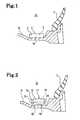
- Fig. 1shows an installation structure for an electronic component for a tire according to a first embodiment of the present invention.
- Rdenotes a rim
- Tdenotes a tire
- Sdenotes a tire air chamber.
- a sensor unit 1 for detecting information inside the tireis attached to a well portion W of the rim R.
- the sensor unit 1includes an electronic component 3 inside a case 2 made of resin, measures an air pressure of the tire T and an internal temperature thereof, and transmits the results to the outside of the tire.
- the case 2 of the sensor unit 1is fixed to the well portion W of the rim R by use of mechanical attachment means such as screws or by adhesion.
- An attachment force of the case 2 to the well portion Wis set to be smaller than a breaking stress of the case 2.
- the case 2 for receiving the electronic component 3is never destroyed, and the sensor unit 1 can be reused.
- Fig. 2shows an installation structure for an electronic component for a tire according to a second embodiment of the present invention.
- Rdenotes a rim
- Tdenotes a tire
- Sdenotes a tire air chamber.
- a sensor unit 11 for detecting information inside the tireis attached to a well portion W of the rim R by means of a base 14.
- the sensor unit 11includes an electronic component 13 inside a case 12 made of resin, measures an air pressure of the tire T and an internal temperature thereof, and transmits the results to the outside of the tire.
- the base 14includes at least a pair of locking parts 16 and 16 which are protruded from a bottom part 15. These locking parts 16 and 16 lock the case 12 of the sensor unit 11 by sandwiching the case.
- the base 14is fixed to the well portion W of the rim R by use of mechanical attachment means such as screws or by adhesion.
- An attachment force of the base 14 to the well portion Wis set to be smaller than a breaking stress of the case 12.
- the installation structure thus configured for an electronic component for a tireduring attachment and removal of the tire T to and from a wheel, when a bead toe portion of the tire T comes into contact with the case 12 of the sensor unit 11 or the base 14, and the case 12 is subjected to external force applied in an axial direction of the tire, the base 14 is separated from the well portion W before the case 12 is destroyed by the force.
- the case 12 for receiving the electronic component 13is never destroyed, and the sensor unit 11 can be reused.
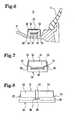
- Fig. 3shows an installation structure for an electronic component for a tire according to a third embodiment of the present invention.
- Figs. 4 and 5show a main part of the structure.
- Rdenotes a rim
- Tdenotes a tire
- Sdenotes a tire air chamber.
- a sensor unit 21 for detecting information inside the tireis attached to a well portion W of the rim R by means of a base 24.
- the sensor unit 21includes an electronic component 23 inside a case 22 made of resin, measures an air pressure of the tire T and an internal temperature thereof, and transmits the results to the outside of the tire.
- the base 24includes at least a pair of locking parts 26 and 26 which are protruded from a bottom part 25. These locking parts 26 and 26 lock the case 22 of the sensor unit 21 by sandwiching the case. As shown in Figs. 4 and 5 , the respective locking parts 26 of the base 24 have holes 27 formed therein, and protrusions 28 are provided at positions corresponding to the holes 27 in the case 22 of the sensor unit 21. Specifically, the case 22 is attached to the base 24 while deforming the locking parts 26 and 26 outward. In the attachment state described above, the case 22 is locked to the base 24 by inserting the protrusions 28 into the holes 27.
- the base 24is fixed to the well portion W of the rim R by use of mechanical attachment means such as screws or by adhesion.
- a mechanical strength of the base 24is set to be lower than a mechanical strength of the case 22.
- the installation structure thus configured for an electronic component for a tireduring attachment and removal of the tire T to and from a wheel, when a bead toe portion of the tire T comes into contact with the case 22 of the sensor unit 21 or the base 24, and the case 22 is subjected to external force applied in an axial direction of the tire, the base 24 is deformed or destroyed before the case 22 is destroyed by the force. Accordingly, the case 22 is separated from the base 24.
- the case 22 for receiving the electronic component 23is never destroyed, and the sensor unit 21 can be reused.
- Fig. 6shows an installation structure for an electronic component for a tire according to a fourth embodiment of the present invention.
- Figs. 7 and 8show a main part of the structure.
- Rdenotes a rim
- Tdenotes a tire
- Sdenotes a tire air chamber.
- a sensor unit 31 for detecting information inside the tireis attached to a well portion W of the rim R by means of a base 34.
- the sensor unit 31includes an electronic component 33 inside a case 32 made of resin, measures an air pressure of the tire T and an internal temperature thereof, and transmits the results to the outside of the tire.
- the base 34includes at least a pair of supporting parts 36 and 36 which are protruded from a bottom part 35.
- the respective supporting parts 36have holes 38 formed therein, and a binding member 39 such as a band is provided around the case 32 through these holes 38.
- the case 32is attached to the base 34 by use of the binding member 39.
- the base 34is fixed to the well portion W of the rim R by use of mechanical attachment means such as screws or by adhesion.
- a mechanical strength of the binding member 39is set to be lower than a mechanical strength of the case 32.
- the binding member 39can hold the case 32 against force such as centrifugal force assumed to be generated during running. However, the binding member 39 is deformed or broken if much greater force is applied thereto.
- the installation structure thus configured for an electronic component for a tireduring attachment and removal of the tire T to and from a wheel, when a bead toe portion of the tire T comes into contact with the case 32 of the sensor unit 31, the base 34 or the binding member 39, and the case 32 is subjected to external force applied in an axial direction of the tire, the binding member 39 is deformed or destroyed before the case 32 is destroyed by the force. Accordingly, the case 32 is separated from the base 34.
- the case 32 for receiving the electronic component 33is never destroyed, and the sensor unit 31 can be reused.
- Fig. 9shows an installation structure for an electronic component for a tire according to a fifth embodiment of the present invention.
- Figs. 10 and 11show a main part of the structure.
- Rdenotes a rim
- Tdenotes a tire
- Sdenotes a tire air chamber.
- a sensor unit 41 for detecting information inside the tireis attached to a well portion W of the rim R by means of a base 44.
- the sensor unit 41includes an electronic component 43 inside a case 42 made of resin, measures an air pressure of the tire T and an internal temperature thereof, and transmits the results to the outside of the tire.
- the base 44is fixed to the well portion W of the rim R by use of mechanical attachment means such as screws or by adhesion.
- the base 44includes fitting holes 46 extended in an axial direction of the tire, respectively, on both ends of a bottom part 45. These fitting holes 46 include narrow portions 47, respectively. Meanwhile, in a lower part of the case 42, a pair of fitting protrusions 48 are provided. A base portion of each of the fitting protrusions 48 is formed to have a rod shape, and a tip portion thereof is formed to have a disc shape. This fitting protrusion 48 is inserted into the fitting hole 46, slid in the axial direction of the tire, and locked in the narrow portion 47. These fitting holes 46 and fitting protrusions 48 form a fitting mechanism 49. Specifically, this fitting mechanism 49 allows only slide of the case 42 in the axial direction of the tire, and fitting of the base 44 and the case 42 is released by the slide.
- the installation structure thus configured for an electronic component for a tireduring attachment and removal of the tire T to and from a wheel, when a bead toe portion of the tire T comes into contact with the case 42 of the sensor unit 41, and the case 42 is subjected to external force applied in the axial direction of the tire, the fitting of the base 44 and the case 42 by the fitting mechanism 49 is released before the case 42 is destroyed by the force. Accordingly, the case 42 is separated from the base 44.
- the case 42 for receiving the electronic component 43is never destroyed, and the sensor unit 41 can be reused.
- the sensor unit including the electronic component housed in the casecan be protected.
- the base or the binding membermay be destroyed.
- these base and binding memberare inexpensive and may be replaced when destroyed.
- materials of the base and the binding memberare not particularly limited.
- metalsuch as aluminum, resin, rubber, and the like can be used.
- the present inventioncan be effectively utilized in tire manufacturing industries and thus in automobile manufacturing industries.
Landscapes
- Engineering & Computer Science (AREA)
- Mechanical Engineering (AREA)
- Measuring Fluid Pressure (AREA)
- Tires In General (AREA)
Abstract
Description
- The present invention relates to an installation structure in which an electronic component for detecting information inside a tire such as an air pressure and a temperature is attached to a rim well portion in a tire air chamber. More particularly, the present invention relates to an installation structure for an electronic component for a tire, where a case for the electronic component attached to a rim well portion is prevented from being destroyed during attachment and removal of the tire to and from a wheel.
- In order to monitor information inside a tire, such as an air pressure and a temperature, there has been heretofore performed attachment of a sensor unit to a well portion of a rim, detection of the information inside the tire by use of the sensor unit, and transmission of the result to a receiver outside of the tire by utilizing radio waves (for example, see Japanese patent application Kohyo publication No.
Hei 10 (1998)-504783 WO1/76894 - However, if the sensor unit is attached to the well portion of the rim, a bead toe portion of the tire comes into contact with the sensor unit during attachment and removal of the tire to and from the wheel, particularly, when the tire is removed from the rim. Accordingly, a case for receiving the electronic component is often destroyed.
US 4,507,956 teaches a circuit mounting apparatus for a tire in which an electrical circuit element encased in a plastic housing is held in place by wires which are connected to the ends of an extension spring which prohibits breaking the housing of the electrical element upon assembly of a tire in that the force exerted by the tire will displace the circuit assembly without damage.EP 0 775 601 A1 teaches a security device with an integrated pressure sensor. Onto the rim of a wheel, a ring-shaped mount is fixed having a recession and at the bottom thereof lateral clefts. A specifically shaped sensor module with a base adapted to be hosted by the cleft is inserted into the recess and upon turning it by 90°, the base locks with the clefts.US 5,260,683 is directed to a further pressure detecting apparatus for a vehicle in which a case is attached to a rim of a wheel, in which case a pressure detecting portion is incorporated. Case and pressure detecting portion will be preassembled before attaching them to the rim.- It is an object of the present invention to provide an
installation 25 structure for an electronic component for a tire, where a case for the electronic component attached to a rim well portion can be prevented from being destroyed during attachment and removal of the tire to and from a wheel. - An installation structure for an electronic component for a tire of the present invention to achieve the foregoing object is a structure, in which the electronic component received in a case is attached to a rim well portion in a tire air chamber, characterized in that an attachment force of the case to the rim well portion is set to be smaller than a breaking stress of the case, by means of an adhesive agent.
- Here, setting the attachment force of the case to the rim well portion to be smaller than the breaking stress of the case means that, when the case is subjected to external force applied in an axial direction of the tire, the case is separated from the rim well portion before it is destroyed by the force.
- Moreover, an installation structure for an electronic component for a tire of the present invention to achieve the foregoing object is a structure, in which the electronic component received in a case is attached to a rim well portion in a tire air chamber, characterized in that a base is previously attached to the rim well portion, the case is attached to the base, and an attachment force of the base to the rim well portion is set to be smaller than a breaking stress of the case.
- Here, setting the attachment force of the base to the rim well portion to be smaller than the breaking stress of the case means that, when the case is subjected to external force applied in an axial direction of the tire, the base is separated from the rim well portion before the case is destroyed by the force.
- Furthermore, an installation structure of the present invention for an electronic component for a tire to achieve the foregoing object is a structure, in which the electronic component received in a case is attached to a rim well portion in a tire air chamber, characterized in that a base is previously attached to the rim well portion, the case is attached to the base by means of a binding member, and a mechanical strength of the binding member is set to be lower than a mechanical strength of the case.
- Here, setting the mechanical strength of the binding member to be lower than the mechanical strength of the case means that, when the case is subjected to external force applied in an axial direction of the tire, the binding member is deformed or destroyed before the case is destroyed by the force, and the case is separated from the base.
- In the present invention, when the case for receiving the electronic component is subjected to external force applied in a radial direction of the tire, the case is positionaily released from a fixed state before it is destroyed by the force and set to be in a freely movable state. Therefore, even if a bead toe portion of the tire comes into contact with the case for the electronic component during attachment and removal of the tire to and from a wheel, the case is unlikely to be destroyed. As a result, a sensor unit including the electronic component and the case can be efficiently reused.
- Note that the electronic component means a pressure sensor, a temperature sensor, a transmitter, a receiver, a control circuit, a battery or the like. These electronic components are usually received in a case and unitized.
Fig. 1 is a cross-sectional view schematically showing an installation structure for an electronic component for a tire according to a first embodiment of the present invention.Fig. 2 is a cross-sectional view schematically showing an installation structure for an electronic component for a tire according to a second embodiment of the present invention.Fig. 3 is a cross-sectional view schematically showing an installation structure for an electronic component for a tire according to a third embodiment of the present invention.Fig. 4 is a front view showing a partially cut out sensor unit and base, which are used in the installation structure for an electronic component for a tire according to the third embodiment of the present invention.Fig. 5 is a side view showing the sensor unit and the base, which are used in the installation structure for an electronic component for a tire according to the third embodiment of the present invention.Fig. 6 is a cross-sectional view schematically showing an installation structure for an electronic component for a tire according to a fourth embodiment of the present invention.Fig. 7 is a front view showing a sensor unit and a base, which are used in the installation structure for an electronic component for a tire according to the fourth embodiment of the present invention.Fig. 8 is a side view showing the sensor unit and the base, which are used in the installation structure for an electronic component for a tire according to the fourth embodiment of the present invention.Fig. 9 is a cross-sectional view schematically showing an installation structure for an electronic component for a tire according to a fifth embodiment of the present invention.Fig. 10 is a side view showing a partially cut out sensor unit and base, which are used in the installation structure for an electronic component for a tire according to the fifth embodiment of the present invention.Fig. 11 is a plan view showing the base used in the installation structure for an electronic component for a tire according to the fifth embodiment of the present invention.- With reference to the accompanying drawings, a configuration of the present invention will be described in detail below.
Fig. 1 shows an installation structure for an electronic component for a tire according to a first embodiment of the present invention. InFig. 1 , R denotes a rim, T denotes a tire, and S denotes a tire air chamber. In the structure of this embodiment, a sensor unit 1 for detecting information inside the tire is attached to a well portion W of the rim R. The sensor unit 1 includes anelectronic component 3 inside acase 2 made of resin, measures an air pressure of the tire T and an internal temperature thereof, and transmits the results to the outside of the tire.- The
case 2 of the sensor unit 1 is fixed to the well portion W of the rim R by use of mechanical attachment means such as screws or by adhesion. An attachment force of thecase 2 to the well portion W is set to be smaller than a breaking stress of thecase 2. - In the installation structure thus configured for an electronic component for a tire, during attachment and removal of the tire T to and from a wheel, when a bead toe portion of the tire T comes into contact with the
case 2 of the sensor unit 1, and thecase 2 is subjected to external force applied in an axial direction of the tire, thecase 2 is separated from the well portion W before it is destroyed by the force. Thus, during attachment and removal of the tire T to and from the wheel, thecase 2 for receiving theelectronic component 3 is never destroyed, and the sensor unit 1 can be reused. Fig. 2 shows an installation structure for an electronic component for a tire according to a second embodiment of the present invention. InFig. 2 , R denotes a rim, T denotes a tire, and S denotes a tire air chamber. In the structure of this embodiment, asensor unit 11 for detecting information inside the tire is attached to a well portion W of the rim R by means of abase 14. Thesensor unit 11 includes anelectronic component 13 inside acase 12 made of resin, measures an air pressure of the tire T and an internal temperature thereof, and transmits the results to the outside of the tire.- The
base 14 includes at least a pair oflocking parts bottom part 15. Theselocking parts case 12 of thesensor unit 11 by sandwiching the case. - The
base 14 is fixed to the well portion W of the rim R by use of mechanical attachment means such as screws or by adhesion. An attachment force of thebase 14 to the well portion W is set to be smaller than a breaking stress of thecase 12. - In the installation structure thus configured for an electronic component for a tire, during attachment and removal of the tire T to and from a wheel, when a bead toe portion of the tire T comes into contact with the
case 12 of thesensor unit 11 or thebase 14, and thecase 12 is subjected to external force applied in an axial direction of the tire, thebase 14 is separated from the well portion W before thecase 12 is destroyed by the force. Thus, during attachment and removal of the tire T to and from the wheel, thecase 12 for receiving theelectronic component 13 is never destroyed, and thesensor unit 11 can be reused. Fig. 3 shows an installation structure for an electronic component for a tire according to a third embodiment of the present invention.Figs. 4 and 5 show a main part of the structure. InFig. 3 , R denotes a rim, T denotes a tire, and S denotes a tire air chamber. In the structure of this embodiment, asensor unit 21 for detecting information inside the tire is attached to a well portion W of the rim R by means of abase 24. Thesensor unit 21 includes anelectronic component 23 inside acase 22 made of resin, measures an air pressure of the tire T and an internal temperature thereof, and transmits the results to the outside of the tire.- The
base 24 includes at least a pair oflocking parts bottom part 25. Theselocking parts case 22 of thesensor unit 21 by sandwiching the case. As shown inFigs. 4 and 5 , therespective locking parts 26 of the base 24 haveholes 27 formed therein, andprotrusions 28 are provided at positions corresponding to theholes 27 in thecase 22 of thesensor unit 21. Specifically, thecase 22 is attached to the base 24 while deforming the lockingparts case 22 is locked to thebase 24 by inserting theprotrusions 28 into theholes 27. - The
base 24 is fixed to the well portion W of the rim R by use of mechanical attachment means such as screws or by adhesion. A mechanical strength of thebase 24 is set to be lower than a mechanical strength of thecase 22. - In the installation structure thus configured for an electronic component for a tire, during attachment and removal of the tire T to and from a wheel, when a bead toe portion of the tire T comes into contact with the
case 22 of thesensor unit 21 or thebase 24, and thecase 22 is subjected to external force applied in an axial direction of the tire, thebase 24 is deformed or destroyed before thecase 22 is destroyed by the force. Accordingly, thecase 22 is separated from thebase 24. Thus, during attachment and removal of the tire T to and from the wheel, thecase 22 for receiving theelectronic component 23 is never destroyed, and thesensor unit 21 can be reused. Fig. 6 shows an installation structure for an electronic component for a tire according to a fourth embodiment of the present invention.Figs. 7 and 8 show a main part of the structure. InFig. 6 , R denotes a rim, T denotes a tire, and S denotes a tire air chamber. In the structure of this embodiment, asensor unit 31 for detecting information inside the tire is attached to a well portion W of the rim R by means of abase 34. Thesensor unit 31 includes anelectronic component 33 inside acase 32 made of resin, measures an air pressure of the tire T and an internal temperature thereof, and transmits the results to the outside of the tire.- As shown in
Figs. 7 and 8 , thebase 34 includes at least a pair of supportingparts bottom part 35. In these supportingparts claws case 32 in a circumferential direction of the tire, respectively. Moreover, the respective supportingparts 36 haveholes 38 formed therein, and a bindingmember 39 such as a band is provided around thecase 32 through theseholes 38. Specifically, thecase 32 is attached to thebase 34 by use of the bindingmember 39. - The
base 34 is fixed to the well portion W of the rim R by use of mechanical attachment means such as screws or by adhesion. A mechanical strength of the bindingmember 39 is set to be lower than a mechanical strength of thecase 32. To be more specific, the bindingmember 39 can hold thecase 32 against force such as centrifugal force assumed to be generated during running. However, the bindingmember 39 is deformed or broken if much greater force is applied thereto. - In the installation structure thus configured for an electronic component for a tire, during attachment and removal of the tire T to and from a wheel, when a bead toe portion of the tire T comes into contact with the
case 32 of thesensor unit 31, the base 34 or the bindingmember 39, and thecase 32 is subjected to external force applied in an axial direction of the tire, the bindingmember 39 is deformed or destroyed before thecase 32 is destroyed by the force. Accordingly, thecase 32 is separated from thebase 34. Thus, during attachment and removal of the tire T to and from the wheel, thecase 32 for receiving theelectronic component 33 is never destroyed, and thesensor unit 31 can be reused. Fig. 9 shows an installation structure for an electronic component for a tire according to a fifth embodiment of the present invention.Figs. 10 and 11 show a main part of the structure. InFig. 9 , R denotes a rim, T denotes a tire, and S denotes a tire air chamber. In the structure of this embodiment, asensor unit 41 for detecting information inside the tire is attached to a well portion W of the rim R by means of abase 44. Thesensor unit 41 includes anelectronic component 43 inside acase 42 made of resin, measures an air pressure of the tire T and an internal temperature thereof, and transmits the results to the outside of the tire. Thebase 44 is fixed to the well portion W of the rim R by use of mechanical attachment means such as screws or by adhesion.- As shown in
Figs. 10 and 11 , thebase 44 includesfitting holes 46 extended in an axial direction of the tire, respectively, on both ends of abottom part 45. Thesefitting holes 46 includenarrow portions 47, respectively. Meanwhile, in a lower part of thecase 42, a pair offitting protrusions 48 are provided. A base portion of each of thefitting protrusions 48 is formed to have a rod shape, and a tip portion thereof is formed to have a disc shape. Thisfitting protrusion 48 is inserted into thefitting hole 46, slid in the axial direction of the tire, and locked in thenarrow portion 47. Thesefitting holes 46 andfitting protrusions 48 form afitting mechanism 49. Specifically, thisfitting mechanism 49 allows only slide of thecase 42 in the axial direction of the tire, and fitting of thebase 44 and thecase 42 is released by the slide. - In the installation structure thus configured for an electronic component for a tire, during attachment and removal of the tire T to and from a wheel, when a bead toe portion of the tire T comes into contact with the
case 42 of thesensor unit 41, and thecase 42 is subjected to external force applied in the axial direction of the tire, the fitting of thebase 44 and thecase 42 by thefitting mechanism 49 is released before thecase 42 is destroyed by the force. Accordingly, thecase 42 is separated from thebase 44. Thus, during attachment and removal of the tire T to and from the wheel, thecase 42 for receiving theelectronic component 43 is never destroyed, and thesensor unit 41 can be reused. - In the present invention, as described above, the sensor unit including the electronic component housed in the case can be protected. On the other hand, the base or the binding member may be destroyed. However, these base and binding member are inexpensive and may be replaced when destroyed. Note that materials of the base and the binding member are not particularly limited. For example, metal such as aluminum, resin, rubber, and the like can be used.
- Although the embodiments of the present invention have been described in detail above, it should be understood that various changes, alternatives, and substitutions can be made without departing from the scope of the present invention, which are defined by the attached claims.
- The present invention can be effectively utilized in tire manufacturing industries and thus in automobile manufacturing industries.
Claims (3)
- An installation structure for an electronic component (3) for a tire (T), in which the force of attachment of a case (2) with the electronic component (3) received therein to a rim well portion (W) in an air chamber (S) of the tire (T) is set to be smaller than a breaking stress of the case (2),characterized in that the case (2) is attached to the rim well portion (W) by means of an adhesive agent.
- An installation structure for an electronic component (13) for a tire (T), in which a base (14) is previously attached to a rim well portion (W) in an air chamber (S) of the tire (T) and then a case (12) with the electronic component (13) received therein is attached to the base (14),characterized in that the force of the attachment of the base (14) to the rim well portion (W) is set to be smaller than a breaking stress of the case (12).
- An installation structure for an electronic component (33) for a tire (T), in which a base (34) is previously attached to a rim well portion (W) in an air chamber (S) of the tire (T) and then a case (32) with the electronic component (33) received therein is attached to the base (34),characterized in that the case (32) is attached to the base (34) by means of a binding member (39) and that a mechanical strength of the binding member (39) is set to be lower than a mechanical strength of the case (32).
Applications Claiming Priority (3)
| Application Number | Priority Date | Filing Date | Title |
|---|---|---|---|
| JP2003094870AJP4255301B2 (en) | 2003-03-31 | 2003-03-31 | Mounting structure for tire electronic components |
| JP2003094870 | 2003-03-31 | ||
| PCT/JP2004/004054WO2004087438A1 (en) | 2003-03-31 | 2004-03-24 | Installation structure for electronic component for tire |
Publications (3)
| Publication Number | Publication Date |
|---|---|
| EP1609625A1 EP1609625A1 (en) | 2005-12-28 |
| EP1609625A4 EP1609625A4 (en) | 2006-04-12 |
| EP1609625B1true EP1609625B1 (en) | 2011-12-28 |
Family
ID=33127413
Family Applications (1)
| Application Number | Title | Priority Date | Filing Date |
|---|---|---|---|
| EP04723026AExpired - LifetimeEP1609625B1 (en) | 2003-03-31 | 2004-03-24 | Installation structure for electronic component for tire |
Country Status (6)
| Country | Link |
|---|---|
| US (1) | US7350407B2 (en) |
| EP (1) | EP1609625B1 (en) |
| JP (1) | JP4255301B2 (en) |
| CN (1) | CN100398346C (en) |
| CA (1) | CA2515907C (en) |
| WO (1) | WO2004087438A1 (en) |
Families Citing this family (22)
| Publication number | Priority date | Publication date | Assignee | Title |
|---|---|---|---|---|
| JP4166735B2 (en)* | 2004-08-04 | 2008-10-15 | 太平洋工業株式会社 | Transmitter unit in tire condition monitoring device |
| DE102004037956A1 (en)* | 2004-08-05 | 2006-02-23 | Dr.Ing.H.C. F. Porsche Ag | Wheel sensor for tire pressure monitoring device with holder |
| FR2874540B1 (en)* | 2004-09-01 | 2006-11-24 | Siemens Vdo Automotive Sas | SUPPORT FOR A PNEUMATIC PRESSURE SENSOR |
| JP4684044B2 (en)* | 2005-08-23 | 2011-05-18 | 株式会社ブリヂストン | Detector fixing structure |
| JP4602230B2 (en)* | 2005-10-31 | 2010-12-22 | マクセル精器株式会社 | Mounting device for tire pressure detecting device |
| JP4778786B2 (en)* | 2005-12-12 | 2011-09-21 | 株式会社ブリヂストン | Electronic device mounting structure and pneumatic tire |
| JP4980621B2 (en) | 2006-01-06 | 2012-07-18 | 株式会社ブリヂストン | Mounting patch structure and pneumatic tire |
| EP2015942B1 (en)* | 2006-04-26 | 2016-04-06 | Pirelli Tyre S.p.A. | A tyre comprising an electronic unit |
| JP4892283B2 (en)* | 2006-06-09 | 2012-03-07 | 株式会社ブリヂストン | Electronic device mounting structure and pneumatic tire |
| JP2008105596A (en)* | 2006-10-26 | 2008-05-08 | Yokohama Rubber Co Ltd:The | Tire information detecting transmitter |
| ITMO20070177A1 (en)* | 2007-05-24 | 2008-11-25 | Zadi S P A | GROUP FOR THE MEASUREMENT OF PHYSICAL PARAMETERS RELATED TO THE STATE OF A TIRE. |
| CN101863201B (en)* | 2010-06-24 | 2013-09-18 | 广东铁将军防盗设备有限公司 | Tire pressure meter and air tap connecting structure |
| CN201751216U (en)* | 2010-06-24 | 2011-02-23 | 广东铁将军防盗设备有限公司 | Anti-collision damage reduction structure with air nozzle tire pressure gauge |
| CN101863202A (en)* | 2010-06-24 | 2010-10-20 | 广东铁将军防盗设备有限公司 | Anti-collision loss-reducing structure with air nozzle tire pressure meter |
| CN103619616B (en)* | 2011-07-01 | 2015-11-25 | 株式会社普利司通 | installation structure |
| US8640534B2 (en) | 2011-08-22 | 2014-02-04 | Bendix Commercial Vehicle Systems Llc | Mounting method and device for tire pressure monitoring sensor |
| US8881586B2 (en) | 2011-10-27 | 2014-11-11 | Mobile Awareness, Llc | Tire-condition-ascertaining cartridge |
| WO2016099633A1 (en)* | 2014-12-19 | 2016-06-23 | Bridgestone Americas Tire Operations, Llc | Attachment patch for mounting devices |
| JP2017071341A (en)* | 2015-10-08 | 2017-04-13 | 株式会社デンソー | Tire mount sensor and sensor device used in it |
| JP7127309B2 (en) | 2018-03-16 | 2022-08-30 | 横浜ゴム株式会社 | Tire information acquisition device |
| EP3919296B1 (en) | 2020-02-28 | 2023-08-16 | Pacific Industrial Co., Ltd. | Bracket and in-tire electric apparatus |
| US11975572B2 (en) | 2020-02-28 | 2024-05-07 | Pacific Industrial Co., Ltd. | In-tire electric device |
Citations (1)
| Publication number | Priority date | Publication date | Assignee | Title |
|---|---|---|---|---|
| US5260683A (en)* | 1990-04-05 | 1993-11-09 | Nippondenso Co., Ltd. | Tire pressure detecting apparatus for vehicle |
Family Cites Families (23)
| Publication number | Priority date | Publication date | Assignee | Title |
|---|---|---|---|---|
| US4507956A (en)* | 1983-09-09 | 1985-04-02 | Eaton Corporation | Circuit mounting apparatus |
| JPH04146806A (en)* | 1990-10-08 | 1992-05-20 | Nippondenso Co Ltd | Tire air pressure detector fixing device |
| US5473938A (en)* | 1993-08-03 | 1995-12-12 | Mclaughlin Electronics | Method and system for monitoring a parameter of a vehicle tire |
| JPH10504783A (en) | 1994-08-31 | 1998-05-12 | オター コントロールズ リミテッド | Tire condition monitoring system |
| FR2741567B1 (en)* | 1995-11-27 | 1998-01-02 | Michelin & Cie | WHEEL WITH SAFETY SUPPORT AND PRESSURE SENSOR INCORPORATED |
| JP3869909B2 (en) | 1997-05-20 | 2007-01-17 | 横浜ゴム株式会社 | Pneumatic tire internal pressure detection device |
| JP2000103257A (en) | 1998-09-30 | 2000-04-11 | Nippon Seiki Co Ltd | Vehicular instrument device |
| US6161430A (en)* | 1998-10-16 | 2000-12-19 | Bridgestone/Firestone Research Inc. | Device to encapsulate a substrate containing sensitive electronic components and a pressure sensor pack |
| US6868717B2 (en)* | 1998-10-16 | 2005-03-22 | Bridgestone/Firestone North America Tire, Llc | Method and device to encapsulate tire tag |
| EP1235696B1 (en)* | 1999-11-24 | 2009-11-04 | Michelin Recherche Et Technique S.A. | Monitored vehicle tire and monitor retainer assembly |
| FR2807363B1 (en)* | 2000-04-07 | 2003-02-07 | Trw France | TIRE PARAMETER MEASUREMENT SENSOR AND MEASUREMENT SYSTEM COMPRISING THE SAME |
| WO2001076894A1 (en)* | 2000-04-07 | 2001-10-18 | Trw France Sa | Tire condition sensor unit mounting arrangement |
| FR2823148A1 (en) | 2001-04-09 | 2002-10-11 | Michelin Soc Tech | DEVICE FOR FIXING AN ELECTRONIC MONITORING MODULE ON A TIRE |
| DE10131411A1 (en)* | 2001-06-26 | 2003-02-20 | Beru Ag | Wheel for vehicles with pneumatic tires and arrangement of a valve, a device for measuring tire pressure and a spring holding it in the pneumatic tire |
| JP2003182322A (en) | 2001-12-19 | 2003-07-03 | Pacific Ind Co Ltd | Transmitter of tyre state monitoring device |
| TW515764B (en)* | 2002-01-09 | 2003-01-01 | Lite On Automotive Corp | Wheel rim having sensor |
| DE10228737A1 (en)* | 2002-01-09 | 2003-07-24 | Lite On Automotive Corp | Tire condition sensor for pneumatic tires |
| US6805000B1 (en)* | 2002-02-11 | 2004-10-19 | Smartire Systems, Inc. | Apparatus and method for mounting a tire condition sensor capsule to a wheel rim |
| FR2838375B1 (en)* | 2002-04-16 | 2004-05-28 | Siemens Vdo Automotive | DEVICE FOR ARTICULATING A TIRE PRESSURE SENSOR ON A MOTOR VEHICLE RIM |
| JP2003312221A (en) | 2002-04-26 | 2003-11-06 | Pacific Ind Co Ltd | Mounting structure of transmitter for tire state monitoring device |
| JP2004106768A (en) | 2002-09-20 | 2004-04-08 | Bridgestone Corp | Mounting instrument for mounting detection means to wheel rim, wheel equipped with the same, and tire wheel and its forming method |
| US7021133B1 (en)* | 2005-06-16 | 2006-04-04 | Lite-On Automotive Corp. | Tire condition sensing apparatus and mounting method thereof |
| JP2007126026A (en)* | 2005-11-04 | 2007-05-24 | Alps Electric Co Ltd | Antenna device |
- 2003
- 2003-03-31JPJP2003094870Apatent/JP4255301B2/ennot_activeExpired - Fee Related
- 2004
- 2004-03-24CNCNB2004800076679Apatent/CN100398346C/ennot_activeExpired - Lifetime
- 2004-03-24USUS10/546,271patent/US7350407B2/ennot_activeExpired - Lifetime
- 2004-03-24WOPCT/JP2004/004054patent/WO2004087438A1/enactiveApplication Filing
- 2004-03-24CACA002515907Apatent/CA2515907C/ennot_activeExpired - Fee Related
- 2004-03-24EPEP04723026Apatent/EP1609625B1/ennot_activeExpired - Lifetime
Patent Citations (1)
| Publication number | Priority date | Publication date | Assignee | Title |
|---|---|---|---|---|
| US5260683A (en)* | 1990-04-05 | 1993-11-09 | Nippondenso Co., Ltd. | Tire pressure detecting apparatus for vehicle |
Also Published As
| Publication number | Publication date |
|---|---|
| CA2515907C (en) | 2009-01-06 |
| CN1761584A (en) | 2006-04-19 |
| CN100398346C (en) | 2008-07-02 |
| US20060144133A1 (en) | 2006-07-06 |
| EP1609625A4 (en) | 2006-04-12 |
| CA2515907A1 (en) | 2004-10-14 |
| US7350407B2 (en) | 2008-04-01 |
| JP4255301B2 (en) | 2009-04-15 |
| EP1609625A1 (en) | 2005-12-28 |
| WO2004087438A1 (en) | 2004-10-14 |
| JP2004299535A (en) | 2004-10-28 |
Similar Documents
| Publication | Publication Date | Title |
|---|---|---|
| EP1609625B1 (en) | Installation structure for electronic component for tire | |
| KR100516267B1 (en) | Switch assembly for an airbag module attachment | |
| EP1356961B1 (en) | Mounting structure of transmitter for tire condition monitoring apparatus | |
| US20060125612A1 (en) | Valve device | |
| US5090237A (en) | Pressure sensor for determining tire pressure | |
| WO2006132719A2 (en) | Improved package for a tire pressure sensor assembly | |
| US6931920B2 (en) | Tire monitoring system | |
| EP1600780B1 (en) | Rotational sensor | |
| EP3450222B1 (en) | Tire condition detecting apparatus, clamp-in valve and tire valve unit | |
| AU2019332047A1 (en) | Fastener | |
| US7370522B2 (en) | Sensor system for tire | |
| EP1268226B1 (en) | Tire condition sensor unit mounting arrangement | |
| KR101702746B1 (en) | Apparatus for mounting a printed circuit board | |
| US7503214B2 (en) | Sensor | |
| EP1623848B1 (en) | Transmitter unit and tire condition monitoring apparatus | |
| EP1710098A1 (en) | Tool and method for fixing installation object on wheel | |
| JP5951457B2 (en) | Mirror device | |
| JP5918027B2 (en) | Tire valve unit | |
| US20200298636A1 (en) | Inflation valve for tire rim with limitation of elastic deformation | |
| JP6027416B2 (en) | Mirror device | |
| EP1065107A3 (en) | Mounting structure for fitting a locking collar to a cable reel rotor | |
| CN116848566A (en) | wheel fastener alarm | |
| KR19980051860U (en) | Wheel safety | |
| WO2004026631A3 (en) | Anti-theft device for protecting an automobile and its airbag | |
| JP2003127625A (en) | Tire internal pressure alarm device |
Legal Events
| Date | Code | Title | Description |
|---|---|---|---|
| PUAI | Public reference made under article 153(3) epc to a published international application that has entered the european phase | Free format text:ORIGINAL CODE: 0009012 | |
| 17P | Request for examination filed | Effective date:20050909 | |
| AK | Designated contracting states | Kind code of ref document:A1 Designated state(s):AT BE BG CH CY CZ DE DK EE ES FI FR GB GR HU IE IT LI LU MC NL PL PT RO SE SI SK TR | |
| AX | Request for extension of the european patent | Extension state:AL LT LV MK | |
| A4 | Supplementary search report drawn up and despatched | Effective date:20060223 | |
| DAX | Request for extension of the european patent (deleted) | ||
| RBV | Designated contracting states (corrected) | Designated state(s):DE FR GB | |
| 17Q | First examination report despatched | Effective date:20061130 | |
| GRAP | Despatch of communication of intention to grant a patent | Free format text:ORIGINAL CODE: EPIDOSNIGR1 | |
| GRAS | Grant fee paid | Free format text:ORIGINAL CODE: EPIDOSNIGR3 | |
| GRAA | (expected) grant | Free format text:ORIGINAL CODE: 0009210 | |
| AK | Designated contracting states | Kind code of ref document:B1 Designated state(s):DE FR GB | |
| REG | Reference to a national code | Ref country code:GB Ref legal event code:FG4D | |
| RIN1 | Information on inventor provided before grant (corrected) | Inventor name:SHIMURA, KAZUHIRO,C/O THE YOKOHAMA RUBBER CO., LTD | |
| REG | Reference to a national code | Ref country code:DE Ref legal event code:R096 Ref document number:602004035865 Country of ref document:DE Effective date:20120322 | |
| PLBE | No opposition filed within time limit | Free format text:ORIGINAL CODE: 0009261 | |
| STAA | Information on the status of an ep patent application or granted ep patent | Free format text:STATUS: NO OPPOSITION FILED WITHIN TIME LIMIT | |
| 26N | No opposition filed | Effective date:20121001 | |
| REG | Reference to a national code | Ref country code:DE Ref legal event code:R097 Ref document number:602004035865 Country of ref document:DE Effective date:20121001 | |
| REG | Reference to a national code | Ref country code:FR Ref legal event code:PLFP Year of fee payment:13 | |
| REG | Reference to a national code | Ref country code:FR Ref legal event code:PLFP Year of fee payment:14 | |
| REG | Reference to a national code | Ref country code:FR Ref legal event code:PLFP Year of fee payment:15 | |
| PGFP | Annual fee paid to national office [announced via postgrant information from national office to epo] | Ref country code:FR Payment date:20210210 Year of fee payment:18 | |
| PGFP | Annual fee paid to national office [announced via postgrant information from national office to epo] | Ref country code:GB Payment date:20210318 Year of fee payment:18 | |
| GBPC | Gb: european patent ceased through non-payment of renewal fee | Effective date:20220324 | |
| PG25 | Lapsed in a contracting state [announced via postgrant information from national office to epo] | Ref country code:GB Free format text:LAPSE BECAUSE OF NON-PAYMENT OF DUE FEES Effective date:20220324 Ref country code:FR Free format text:LAPSE BECAUSE OF NON-PAYMENT OF DUE FEES Effective date:20220331 | |
| PGFP | Annual fee paid to national office [announced via postgrant information from national office to epo] | Ref country code:DE Payment date:20230131 Year of fee payment:20 | |
| P01 | Opt-out of the competence of the unified patent court (upc) registered | Effective date:20230512 | |
| REG | Reference to a national code | Ref country code:DE Ref legal event code:R071 Ref document number:602004035865 Country of ref document:DE |