EP1608295B1 - Double ended intravascular medical device - Google Patents
Double ended intravascular medical deviceDownload PDFInfo
- Publication number
- EP1608295B1 EP1608295B1EP04758510.4AEP04758510AEP1608295B1EP 1608295 B1EP1608295 B1EP 1608295B1EP 04758510 AEP04758510 AEP 04758510AEP 1608295 B1EP1608295 B1EP 1608295B1
- Authority
- EP
- European Patent Office
- Prior art keywords
- catheter
- sheath
- medical device
- elongated member
- filter
- Prior art date
- Legal status (The legal status is an assumption and is not a legal conclusion. Google has not performed a legal analysis and makes no representation as to the accuracy of the status listed.)
- Expired - Lifetime
Links
- 230000003073embolic effectEffects0.000claimsdescription29
- 238000003780insertionMethods0.000claimsdescription5
- 230000037431insertionEffects0.000claimsdescription5
- 230000002792vascularEffects0.000claimsdescription5
- 238000011084recoveryMethods0.000description23
- 238000000034methodMethods0.000description21
- 239000000463materialSubstances0.000description18
- 239000012530fluidSubstances0.000description10
- 239000007787solidSubstances0.000description10
- 210000005166vasculatureAnatomy0.000description9
- 238000000576coating methodMethods0.000description8
- 229920000642polymerPolymers0.000description8
- 208000007536ThrombosisDiseases0.000description7
- 230000006870functionEffects0.000description7
- 238000004806packaging method and processMethods0.000description7
- 210000001367arteryAnatomy0.000description6
- 210000004204blood vesselAnatomy0.000description6
- 230000037361pathwayEffects0.000description6
- 208000005189EmbolismDiseases0.000description5
- 238000002399angioplastyMethods0.000description5
- 230000017531blood circulationEffects0.000description5
- 239000012528membraneSubstances0.000description5
- 238000004891communicationMethods0.000description4
- 210000004351coronary vesselAnatomy0.000description4
- 239000012634fragmentSubstances0.000description4
- 230000001681protective effectEffects0.000description4
- 229920002614Polyether block amidePolymers0.000description3
- 239000002131composite materialSubstances0.000description3
- 201000010099diseaseDiseases0.000description3
- 208000037265diseases, disorders, signs and symptomsDiseases0.000description3
- 229910052751metalInorganic materials0.000description3
- 239000002184metalSubstances0.000description3
- 208000010125myocardial infarctionDiseases0.000description3
- 230000008569processEffects0.000description3
- BLDFSDCBQJUWFG-UHFFFAOYSA-N2-(methylamino)-1,2-diphenylethanolChemical compoundC=1C=CC=CC=1C(NC)C(O)C1=CC=CC=C1BLDFSDCBQJUWFG-UHFFFAOYSA-N0.000description2
- 206010003210ArteriosclerosisDiseases0.000description2
- 201000001320AtherosclerosisDiseases0.000description2
- 208000037260Atherosclerotic PlaqueDiseases0.000description2
- VGGSQFUCUMXWEO-UHFFFAOYSA-NEtheneChemical compoundC=CVGGSQFUCUMXWEO-UHFFFAOYSA-N0.000description2
- HTTJABKRGRZYRN-UHFFFAOYSA-NHeparinChemical compoundOC1C(NC(=O)C)C(O)OC(COS(O)(=O)=O)C1OC1C(OS(O)(=O)=O)C(O)C(OC2C(C(OS(O)(=O)=O)C(OC3C(C(O)C(O)C(O3)C(O)=O)OS(O)(=O)=O)C(CO)O2)NS(O)(=O)=O)C(C(O)=O)O1HTTJABKRGRZYRN-UHFFFAOYSA-N0.000description2
- 208000031481Pathologic ConstrictionDiseases0.000description2
- 230000001464adherent effectEffects0.000description2
- TZCXTZWJZNENPQ-UHFFFAOYSA-Lbarium sulfateChemical compound[Ba+2].[O-]S([O-])(=O)=OTZCXTZWJZNENPQ-UHFFFAOYSA-L0.000description2
- HVYWMOMLDIMFJA-DPAQBDIFSA-NcholesterolChemical compoundC1C=C2C[C@@H](O)CC[C@]2(C)[C@@H]2[C@@H]1[C@@H]1CC[C@H]([C@H](C)CCCC(C)C)[C@@]1(C)CC2HVYWMOMLDIMFJA-DPAQBDIFSA-N0.000description2
- 230000003292diminished effectEffects0.000description2
- 239000013013elastic materialSubstances0.000description2
- 229920000295expanded polytetrafluoroethylenePolymers0.000description2
- 229960002897heparinDrugs0.000description2
- 229920000669heparinPolymers0.000description2
- 230000002209hydrophobic effectEffects0.000description2
- 239000007943implantSubstances0.000description2
- 229920001684low density polyethylenePolymers0.000description2
- 239000004702low-density polyethyleneSubstances0.000description2
- 229920001179medium density polyethylenePolymers0.000description2
- 239000004701medium-density polyethyleneSubstances0.000description2
- 239000007769metal materialSubstances0.000description2
- 239000000203mixtureSubstances0.000description2
- 238000012986modificationMethods0.000description2
- 230000004048modificationEffects0.000description2
- HLXZNVUGXRDIFK-UHFFFAOYSA-Nnickel titaniumChemical compound[Ti].[Ti].[Ti].[Ti].[Ti].[Ti].[Ti].[Ti].[Ti].[Ti].[Ti].[Ni].[Ni].[Ni].[Ni].[Ni].[Ni].[Ni].[Ni].[Ni].[Ni].[Ni].[Ni].[Ni].[Ni]HLXZNVUGXRDIFK-UHFFFAOYSA-N0.000description2
- 229910001000nickel titaniumInorganic materials0.000description2
- 230000002093peripheral effectEffects0.000description2
- 229920001296polysiloxanePolymers0.000description2
- 229920000036polyvinylpyrrolidonePolymers0.000description2
- 235000013855polyvinylpyrrolidoneNutrition0.000description2
- 239000001267polyvinylpyrrolidoneSubstances0.000description2
- 239000000126substanceSubstances0.000description2
- 238000013151thrombectomyMethods0.000description2
- 206010002383Angina PectorisDiseases0.000description1
- 229910000014Bismuth subcarbonateInorganic materials0.000description1
- 229920000049Carbon (fiber)Polymers0.000description1
- 229920000106Liquid crystal polymerPolymers0.000description1
- 239000004977Liquid-crystal polymers (LCPs)Substances0.000description1
- 208000002193PainDiseases0.000description1
- 239000004642PolyimideSubstances0.000description1
- 238000009825accumulationMethods0.000description1
- 239000000853adhesiveSubstances0.000description1
- 230000001070adhesive effectEffects0.000description1
- 238000002266amputationMethods0.000description1
- 210000000709aortaAnatomy0.000description1
- 230000008901benefitEffects0.000description1
- 230000015572biosynthetic processEffects0.000description1
- MGLUJXPJRXTKJM-UHFFFAOYSA-Lbismuth subcarbonateChemical compoundO=[Bi]OC(=O)O[Bi]=OMGLUJXPJRXTKJM-UHFFFAOYSA-L0.000description1
- 229940036358bismuth subcarbonateDrugs0.000description1
- 230000000903blocking effectEffects0.000description1
- 239000008280bloodSubstances0.000description1
- 210000004369bloodAnatomy0.000description1
- 210000004556brainAnatomy0.000description1
- 239000004917carbon fiberSubstances0.000description1
- 230000001413cellular effectEffects0.000description1
- 239000000919ceramicSubstances0.000description1
- 235000012000cholesterolNutrition0.000description1
- 230000006735deficitEffects0.000description1
- 238000013461designMethods0.000description1
- 238000011161developmentMethods0.000description1
- 239000003814drugSubstances0.000description1
- 230000010102embolizationEffects0.000description1
- 210000001105femoral arteryAnatomy0.000description1
- 238000001914filtrationMethods0.000description1
- 238000002594fluoroscopyMethods0.000description1
- 210000004013groinAnatomy0.000description1
- 230000002439hemostatic effectEffects0.000description1
- 238000002347injectionMethods0.000description1
- 239000007924injectionSubstances0.000description1
- 230000003993interactionEffects0.000description1
- 238000013152interventional procedureMethods0.000description1
- 230000003907kidney functionEffects0.000description1
- 230000003902lesionEffects0.000description1
- 150000002632lipidsChemical class0.000description1
- VNWKTOKETHGBQD-UHFFFAOYSA-NmethaneChemical compoundCVNWKTOKETHGBQD-UHFFFAOYSA-N0.000description1
- 230000005012migrationEffects0.000description1
- 238000013508migrationMethods0.000description1
- 230000003836peripheral circulationEffects0.000description1
- 229920003023plasticPolymers0.000description1
- 239000004033plasticSubstances0.000description1
- 229920001721polyimidePolymers0.000description1
- 229920002959polymer blendPolymers0.000description1
- 239000002861polymer materialSubstances0.000description1
- 230000002028prematureEffects0.000description1
- 239000012858resilient materialSubstances0.000description1
- 239000012781shape memory materialSubstances0.000description1
- 230000036262stenosisEffects0.000description1
- 208000037804stenosisDiseases0.000description1
- 230000001225therapeutic effectEffects0.000description1
- 230000000451tissue damageEffects0.000description1
- 231100000827tissue damageToxicity0.000description1
- WFKWXMTUELFFGS-UHFFFAOYSA-NtungstenChemical compound[W]WFKWXMTUELFFGS-UHFFFAOYSA-N0.000description1
- 208000019553vascular diseaseDiseases0.000description1
Images


Classifications
- A—HUMAN NECESSITIES
- A61—MEDICAL OR VETERINARY SCIENCE; HYGIENE
- A61F—FILTERS IMPLANTABLE INTO BLOOD VESSELS; PROSTHESES; DEVICES PROVIDING PATENCY TO, OR PREVENTING COLLAPSING OF, TUBULAR STRUCTURES OF THE BODY, e.g. STENTS; ORTHOPAEDIC, NURSING OR CONTRACEPTIVE DEVICES; FOMENTATION; TREATMENT OR PROTECTION OF EYES OR EARS; BANDAGES, DRESSINGS OR ABSORBENT PADS; FIRST-AID KITS
- A61F2/00—Filters implantable into blood vessels; Prostheses, i.e. artificial substitutes or replacements for parts of the body; Appliances for connecting them with the body; Devices providing patency to, or preventing collapsing of, tubular structures of the body, e.g. stents
- A61F2/01—Filters implantable into blood vessels
- A61F2/011—Instruments for their placement or removal
- A—HUMAN NECESSITIES
- A61—MEDICAL OR VETERINARY SCIENCE; HYGIENE
- A61M—DEVICES FOR INTRODUCING MEDIA INTO, OR ONTO, THE BODY; DEVICES FOR TRANSDUCING BODY MEDIA OR FOR TAKING MEDIA FROM THE BODY; DEVICES FOR PRODUCING OR ENDING SLEEP OR STUPOR
- A61M25/00—Catheters; Hollow probes
- A61M25/0021—Catheters; Hollow probes characterised by the form of the tubing
- A61M25/0023—Catheters; Hollow probes characterised by the form of the tubing by the form of the lumen, e.g. cross-section, variable diameter
- A—HUMAN NECESSITIES
- A61—MEDICAL OR VETERINARY SCIENCE; HYGIENE
- A61M—DEVICES FOR INTRODUCING MEDIA INTO, OR ONTO, THE BODY; DEVICES FOR TRANSDUCING BODY MEDIA OR FOR TAKING MEDIA FROM THE BODY; DEVICES FOR PRODUCING OR ENDING SLEEP OR STUPOR
- A61M25/00—Catheters; Hollow probes
- A61M25/01—Introducing, guiding, advancing, emplacing or holding catheters
- A61M25/09—Guide wires
- A—HUMAN NECESSITIES
- A61—MEDICAL OR VETERINARY SCIENCE; HYGIENE
- A61F—FILTERS IMPLANTABLE INTO BLOOD VESSELS; PROSTHESES; DEVICES PROVIDING PATENCY TO, OR PREVENTING COLLAPSING OF, TUBULAR STRUCTURES OF THE BODY, e.g. STENTS; ORTHOPAEDIC, NURSING OR CONTRACEPTIVE DEVICES; FOMENTATION; TREATMENT OR PROTECTION OF EYES OR EARS; BANDAGES, DRESSINGS OR ABSORBENT PADS; FIRST-AID KITS
- A61F2/00—Filters implantable into blood vessels; Prostheses, i.e. artificial substitutes or replacements for parts of the body; Appliances for connecting them with the body; Devices providing patency to, or preventing collapsing of, tubular structures of the body, e.g. stents
- A61F2/01—Filters implantable into blood vessels
- A61F2/0105—Open ended, i.e. legs gathered only at one side
- A—HUMAN NECESSITIES
- A61—MEDICAL OR VETERINARY SCIENCE; HYGIENE
- A61F—FILTERS IMPLANTABLE INTO BLOOD VESSELS; PROSTHESES; DEVICES PROVIDING PATENCY TO, OR PREVENTING COLLAPSING OF, TUBULAR STRUCTURES OF THE BODY, e.g. STENTS; ORTHOPAEDIC, NURSING OR CONTRACEPTIVE DEVICES; FOMENTATION; TREATMENT OR PROTECTION OF EYES OR EARS; BANDAGES, DRESSINGS OR ABSORBENT PADS; FIRST-AID KITS
- A61F2/00—Filters implantable into blood vessels; Prostheses, i.e. artificial substitutes or replacements for parts of the body; Appliances for connecting them with the body; Devices providing patency to, or preventing collapsing of, tubular structures of the body, e.g. stents
- A61F2/01—Filters implantable into blood vessels
- A61F2002/018—Filters implantable into blood vessels made from tubes or sheets of material, e.g. by etching or laser-cutting
- A—HUMAN NECESSITIES
- A61—MEDICAL OR VETERINARY SCIENCE; HYGIENE
- A61F—FILTERS IMPLANTABLE INTO BLOOD VESSELS; PROSTHESES; DEVICES PROVIDING PATENCY TO, OR PREVENTING COLLAPSING OF, TUBULAR STRUCTURES OF THE BODY, e.g. STENTS; ORTHOPAEDIC, NURSING OR CONTRACEPTIVE DEVICES; FOMENTATION; TREATMENT OR PROTECTION OF EYES OR EARS; BANDAGES, DRESSINGS OR ABSORBENT PADS; FIRST-AID KITS
- A61F2230/00—Geometry of prostheses classified in groups A61F2/00 - A61F2/26 or A61F2/82 or A61F9/00 or A61F11/00 or subgroups thereof
- A61F2230/0002—Two-dimensional shapes, e.g. cross-sections
- A61F2230/0004—Rounded shapes, e.g. with rounded corners
- A61F2230/0008—Rounded shapes, e.g. with rounded corners elliptical or oval
- A—HUMAN NECESSITIES
- A61—MEDICAL OR VETERINARY SCIENCE; HYGIENE
- A61F—FILTERS IMPLANTABLE INTO BLOOD VESSELS; PROSTHESES; DEVICES PROVIDING PATENCY TO, OR PREVENTING COLLAPSING OF, TUBULAR STRUCTURES OF THE BODY, e.g. STENTS; ORTHOPAEDIC, NURSING OR CONTRACEPTIVE DEVICES; FOMENTATION; TREATMENT OR PROTECTION OF EYES OR EARS; BANDAGES, DRESSINGS OR ABSORBENT PADS; FIRST-AID KITS
- A61F2230/00—Geometry of prostheses classified in groups A61F2/00 - A61F2/26 or A61F2/82 or A61F9/00 or A61F11/00 or subgroups thereof
- A61F2230/0063—Three-dimensional shapes
- A61F2230/0073—Quadric-shaped
- A61F2230/008—Quadric-shaped paraboloidal
- A—HUMAN NECESSITIES
- A61—MEDICAL OR VETERINARY SCIENCE; HYGIENE
- A61M—DEVICES FOR INTRODUCING MEDIA INTO, OR ONTO, THE BODY; DEVICES FOR TRANSDUCING BODY MEDIA OR FOR TAKING MEDIA FROM THE BODY; DEVICES FOR PRODUCING OR ENDING SLEEP OR STUPOR
- A61M25/00—Catheters; Hollow probes
Definitions
- the present inventionis related generally to medical devices. More specifically, the present invention is related to intravascular medical devices such as catheters and guidewires.
- Blood vessel diseaseis a significant cause of premature disability and death. Heart attacks, strokes and other ailments are often caused by blood vessel disease.
- Atherosclerosisinvolves the accumulation of plaques of cholesterol, lipids and cellular debris within an artery. As the plaque accumulates, the artery wall thickens thereby narrowing the lumen of the artery. As the lumen narrows, the blood flow to tissue nourished by the artery is diminished. The development of plaques can also contribute to the formation of emboli or thrombi.
- An embolusis a moving obstruction such as a platelet aggregate.
- a thrombuscan be a fixed obstruction such as a wall adherent blood clot or can become an embolus.
- a thrombus or embolus within a coronary arterycan occlude the artery thereby causing myocardial infarction, angina and other conditions.
- a blockage caused by a thrombus or embolus within a vessel supplying blood to the braincan lead to a stroke. Renal, peripheral, and other blood vessels can also become blocked by an embolus or a thrombus thereby causing tissue damage downstream of the blockage.
- a number of medical procedureshave been developed to allow for the removal of plaque from vessel walls or to clear a channel through plaque, thrombus or clot to restore blood flow.
- atherectomy or thrombectomy devicescan be used to remove atheroma or thrombus.
- Vessel restrictionscan also be treated with grafts that bypass the restrictions.
- balloon angioplasty and stenting procedurescan be used to enlarge the lumen size of a vessel at an obstruction.
- a guide wire and guide catheterare inserted into a vessel of a patient.
- An inflatable balloonis then pushed through the guide catheter and advanced across a stenosis or blockage. Once positioned at the blockage, the balloon is inflated to dilate the blockage and open a flow channel through the partially blocked vessel region.
- One or more stentsmay also be placed across the dilated region or regions to reinforce the expanded vessel segment or to maintain dilatation of a vessel segment.
- Consequences of embolizationinclude myocardial infarction, stroke, diminished renal function, and impairment of peripheral circulation possibly leading to pain and amputation.
- Embolic protection deviceshave been developed to prevent the downstream travel of materials such as thrombi, grumous, emboli, and plaque fragments.
- Devicesinclude occlusive devices and filters and may be deployed distal to a treatment site or proximal to a treatment site.
- Occlusive devicesfor example distal inflatable balloon devices, can totally block fluid flow through the vessel. The material trapped by the inflatable devices can remain in place until removed using a method such as aspiration.
- Occlusive devicescan also be deployed proximal to a treatment site and flow reversed or stopped at the treatment site.
- Following treatment emboliare carried by flow out of the vessel typically through a catheter and out of a patient.
- Filterscan allow perfusing blood flow during the emboli capture process.
- the filterscan be advanced downstream of a site to be treated and expanded to increase the filter area.
- Embolisuch as grumous or atheroma fragments, can be captured in the filter until the procedure is complete or the filter is occluded. When the capacity of the filter is reached, the filter may then be retracted and replaced.
- Embolic protection devicescan be delivered over guide wires and within guide catheters.
- the embolic protection methodsare normally practiced ancillary to another medical procedure, for example angioplasty with stenting or atherectomy.
- the embolic protection proceduretypically protects downstream regions from emboli resulting from practicing the therapeutic interventional procedure.
- EP0761250Adescribes a bi-directional catheter for insertion into a body lumen.
- a medical deviceas further disclosed in claim 1, comprising an elongated member configured to be advanced along a vascular path of a patient, the elongated member having opposite first and second ends and corresponding first and second end portions, the first end and second ends both being adapted for intravascular insertion, and the elongated member having a length defined between the first and second ends, the first end portion comprising a delivery sheath and the second end portion comprising a retrieval sheath, defining an internal pocket, the delivery sheath comprising first and second sidewall ports adapted for receiving wires, the first sidewall port being located closer to a free end of the sheath than the second sidewall port, the elongated member further comprising a lumen between the first and second sidewall ports, the lumen having a narrower diameter than the internal pocket provided by a constriction.
- the elongated memberhas sufficient flexibility to be advanced through a human vasculature.
- the first and second endsare adapted to
- the intravascular medical devicecan include any number of different types of devices used in the treatment of vascular disease.
- Example devicesinclude guide wires, catheters, embolic protection device delivery systems and embolic protection device retrieval systems.
- Inventive aspects of the present disclosurerelate to intravascular medical devices having opposite end portions each adapted for insertion within the vasculature of a patient.
- the opposite end portionseach have different operating characteristics such that the medical device is capable of performing different functions depending upon the end of the device that is inserted into the patient.
- Example devicesinclude guide wires, catheters, implant delivery systems, emboli protection device delivery systems, implant retrieval systems, and emboli protection device retrieval systems.
- Fig. 1illustrates an intravascular medical device 20 having features that are examples. It will be appreciated that the intravascular medical device 20 can be embodied in a number of different devices such as catheters, guide wires, embolic filter delivery devices, embolic filter retrieval devices, as well as other devices.
- the medical device 20includes an elongated body 22 having first and second opposite end portions 24,26.
- the elongated body 22is preferably sufficiently flexible to allow the device to be advanced through a curving vascular pathway without kinking and without puncturing the vessel wall.
- the first and second end portions 24 and 26are both capable of leading the elongated member 22 through the vasculature depending upon the direction the elongated member 22 is inserted into the vasculature.
- the first and second end portions 24 and 26preferably have different operating characteristics.
- the first end portion 24can be more flexible than the second end portion 26.
- the first and second end portions 24 and 26can have different pre-formed shapes adapted for facilitating advancement of the medical device 20 along different intravascular pathways.
- the first and second end portions 24 and 26can be adapted for providing different functions.
- the first end portion 24can be adapted for deploying an indwelling medical device such as a stent, graft or embolic protection device
- the second end portion 26can be adapted for retrieving an indwelling medical device such as a stent, graft or embolic protection device.
- the elongated member 22 of the medical device 20includes a main body 28 that extends between the first and second end portions 24 and 26.
- the main body 28can have any number of different types of configurations.
- the main body 28can have a solid configuration such as a solid wire configuration, a solid polymeric configuration, or a composite metal and polymeric configuration.
- the elongated member 22can have a tubular configuration defining a single lumen, or can define a plurality of lumens.
- the main body 28includes a metal having "super elastic"properties such as nitinol.
- the main body 28can also include materials such as carbon fiber and its composites, liquid crystal polymers, ceramics, and composites in general.
- the elongated membermay be coated with hydrophobic, hydrophilic, or biologically active coatings such as poly vinyl pyrrolidone coatings, ePTFE coatings, or heparin coatings.
- the elongated member 22has a length L in the range of 60-300 cm, and an outer diameter D in the range of 0. 013" to 0. 100" (0.033 to 0.25 cm).
- end portions 24 and 26 of the medical devicecan have any number of different configurations.
- end portions 24 and 26can include a polymeric material, a metal material, a combined polymer and metal material, a shape memory material, or a super elastic material.
- the end portions 24, 26can include a solid configuration, or a tubular configuration defining a single lumen or a multi-lumen configuration.
- the end portions 24 and 26can include constant diameter, solid wall tubular, perforated wall tubular, slotted-wall tubular, coiled and any number of other different configurations.
- the first and second end portions 24 and 26can be unitary parts of the main body 28, or can be separate pieces or components that are affixed to the main body 28. It will be appreciated that the lengths and diameters of the end portions 24, 26 will vary depending upon their desired operating characteristics.
- the end portions 24, 26function as flexible guide tips having greater flexibility than the main body 28, and different flexibilities from one another.
- FIG. 2illustrates a catheter 100 having features that are examples.
- the catheter 100includes a central shaft 110 having a first end 112 positioned opposite from a second end 114.
- a tip in the form of a flexible delivery sheath 116is positioned at the first end 112.
- the flexible delivery sheath 116defines an internal pocket 118 (i. e., a compartment, cavity, enclosure, chamber or receptacle) configured for receiving a preloaded device (e. g., a preloaded embolic protection device such as the filter device 70 shown in Figs. 3-5 ).
- the catheter 100also includes a flexible retrieval sheath 120 positioned at the second end 114 of the shaft 110.
- the flexible retrieval sheath 120defines an internal pocket 122 sized and shaped for receiving a medical device (e. g., an embolic protection device such as the filter device 70 of Figs. 3-5 ) for retrieval of the medical device after the device has been used.
- a medical devicee. g., an embolic protection device such as the filter device 70 of Figs. 3-5
- the shaft 110 of the catheter 100is preferably sufficiently flexible and has sufficient column strength to be advanced through the vasculature of a patient.
- the shaft 110includes a solid wire coated with an outer layer of a polymeric material.
- the shaftcould include a tubular metal configuration or other configurations.
- the shaft 110can have a length in the range of 70-170 cm, and more preferably in the range of 100-140 cm.
- the shaft 110can have an outer diameter D in the range of 0.026"-0. 040" (0.066-0. 10 cm).
- the delivery sheath 116 of the catheterpreferably includes a material that is softer and more pliable than the central shaft 110.
- the flexible design of the delivery sheath 116facilitates advancing the catheter 100 through tortuous vessels while the more rigid central shaft 110 can provide pushability.
- the delivery sheath 116is formed of a polymer such as LDPE, MDPE, or PEBAX.
- the outer diameter of the delivery sheathcan be in the range of 0.026-0. 040 inches (0.066-0. 10 cm)
- a wall thickness of the delivery sheathcan be in the range of 0.001 to 0.005 inches (0.0025 to 0.013 cm)
- a length of the delivery sheathcan be in the range of 10 to 40 centimeters.
- the delivery sheath 116includes a first sidewall port 148 and a second sidewall port 150.
- the first and second sidewall ports 148, 150are spaced apart from one another along the length of the sheath 116.
- the first sidewall port 148is located closer to a free end of the sheath 116 than the second sidewall port 150.
- the ports 148, 150are preferably skived and dimensioned to allow a distally and inwardly extending wire to extend from the outside of the sheath 116 to the internal pocket 118 at an angle of less than about 10 relative to a longitudinal axis of the catheter 100. Further details regarding the configuration of the flexible sheath can be found in U. S. Patent Application Publication No. 2003/0233117 A1, published December 18, 2003 , entitled RAPID EXCHANGE CATHETERS USABLE WITH EMBOLIC PROTECTION DEVICES.
- the recovery sheath 120 of the catheter 100is preferably made of a compliant material that is more flexible than the shaft 110.
- the sheath 120has sufficient flexibility to allow the sheath 120 to traverse the tortuous pathways typically encountered within the vasculature of a human.
- Suitable materials for making the sheath 120include thermal plastic polymers, polymer blends and thermal set polymers such as silicone, or silicone blends with a low durometer.
- One such materialis a 35140 D PEBAX blend. Any other appropriate compliant materials may, however, be used.
- the outer diameter of the recovery sheathcan be in the range of 0.040-0. 060 inches (0.10 to 0.15 cm)
- a wall thickness of the recovery sheathcan be in the range of 0.001 to 0.005 inches (0.0025 to 0.013 cm)
- a length of the recovery sheathcan be in the range of 5 to 30 centimeters.
- the recovery sheathhas an outermost end that forms a rolled tip 132.
- the rolled tip 132is especially designed for crossing a stented or otherwise constricted region of a blood vessel.
- the rolled tip 132can also function to capture an implanted device such as an embolic protection device. Further details regarding the recovery sheath 120 can be found in U. S. Patent Application Publication No. 2002/0111649 A1, published August 15, 2002 , entitled ROLLED TIP RECOVERY CATHETER.
- the sheaths 116,120can include one or more bands of radiopaque material, or can be filled with radiopaque material.
- radiopaque materialsinclude barium sulfate, bismuth sub carbonate, tungsten powder, and the like. The presence of radiopaque materials facilitates viewing the sheaths under fluoroscopy.
- the sheaths 116,120may be coated with hydrophobic, hydrophilic, or biologically active coatings such as poly vinyl pyrrolidone coatings, ePTFE coatings, or heparin coatings.
- the catheter 100can also be used for treating other vessels (e. g. , carotid, renal, peripheral, and other blood vessels).
- vesselse. g. , carotid, renal, peripheral, and other blood vessels.
- a physicianfirst inserts a guidewire (not shown) into the femoral artery of a patient near the groin, and advances the guidewire through the artery, over the aorta and to a coronary ostium 21.
- a guide catheter 11is passed over the guidewire and advanced until a distal end of the guide catheter 11 is located adjacent the coronary ostium 21.
- the guidewire (not shown)is then removed.
- a coronary guidewire 19is inserted into the guide catheter and advanced into the coronary artery. See Fig. 3 .
- the proximal end of the coronary guidewire 19is inserted (i.e. back-loaded) through the distal opening of sheath 116 and then the first sidewall port 148 of the delivery catheter 100.
- an embolic protection devicesuch as an embolic filter device 70 is preferably pre-loaded within the delivery sheath 116 of the catheter 100.
- the filter device 70is preferably a self-expandable filter device such as the filter device disclosed in U.S. Patent No. 6,325,815 .
- the filter device 70includes an expandable filter mesh 71 secured to the distal end of a host wire 74. As shown in Fig. 3 , in the pre-loaded configuration, the mesh of the filter device is compressed in a radially reduced profile configuration within the delivery sheath 116, and the host wire 74 extends from the mesh material through the second sidewall port 150 of the delivery sheath 116.
- the filter device 70can be viewed as one type of distal emboli protection element.
- Other distal protection elementswhich can be included as part of the device are occlusive emboli protection elements, including expandable or inflatable elements for blocking fluid flow through a vessel.
- the delivery sheath 116 of the catheter 100is advanced through the guide catheter 11 along the guidewire 19 until the delivery sheath 116 is advanced to the distal tip the guide catheter 11, as shown in Fig. 3 .
- the guidewire 19is then further advanced within the coronary artery to a point where the distal most tip of the guidewire 19 is located at a target site 25 within a coronary artery 23 (e.g., a site located downstream of a treatment site such as an occlusion 27).
- the delivery sheath 116 of the catheter 100can then be tracked along the guide wire 19 to the target site 25 as shown in Fig. 4 .
- the guidewire 19 and the catheter 100can be advanced together across the target site with the guidewire 19 providing stiffening for the catheter 100.
- the filter device 70can be distally advanced to the tip of the delivery sheath 116 and then from the delivery sheath 116.
- the embolic filter 70can be advanced from the sheath 116 by proximally retracting the catheter 100 while the host wire 74 is held in place by the treating physician.
- the sheath 116retracts relative to the filter device 70 thereby exposing the filter device 70 and allowing the filter device 70 to expand radially so as to provide filtration across the entire cross sectional area of the vessel as shown in Fig. 5 .
- the catheter 100can be retracted from the patient, and an interventional device (e.g., a balloon angioplasty catheter, a stent delivery catheter, an atherectomy device, a thrombectomy device or any other device) can be introduced over the host wire 74 and used to treat the treatment site.
- an interventional devicee.g., a balloon angioplasty catheter, a stent delivery catheter, an atherectomy device, a thrombectomy device or any other device
- any emboli generated during the treatment processare captured by the filter 70.
- the interventional deviceis removed and the catheter 100 is reintroduced over the host wire 74.
- the catheter 100is reversed such that the recovery sheath 120 functions as the distal most tip of the catheter 100.
- the host wire 74is passed through the interior of the recovery sheath 120 as shown in Fig. 6 .
- the catheter 100is advanced until the rolled end 132 is positioned immediately proximal to the filter device 70.
- the host wire 74is then pulled in a proximal direction causing a proximal end of the filter device 70 to contact the rolled tip 132.
- the rolled tip 132As the filter device 70 contacts the rolled tip 132, the rolled tip 132 is urged elastically toward an open orientation in which the filter device 70 can be passed into the recovery sheath 120. Once the filter device 70 has been fully drawn into the sheath 120 as shown in Fig. 7 , the rolled tip 132 reaches a point where it ceases to be engaged by the filter device 70, and it elastically returns to its undeflected configuration. It will be appreciated that the resilient material forming the sheath 120 prevents the escape of emboli when the filter device 70 is captured. Preferably, at least a portion of the wall of the sheath 120 closely encompasses the periphery of the filter device 70 and assumes the shape of the periphery.
- emboliare prevented from passing between the periphery of the filter device 70 and the wall of the sheath 120.
- the filter device 70can be partly drawn into the recovery sheath 120 such that only the enlarged proximal opening of the filter is within the sheath.
- both the host wire 74 and the catheter 100can be withdrawn from the patient together as a unit. Thereafter, the procedure is completed by removing the guide catheter 22 from the patient.
- Figs. 8 and 9illustrate an alternative catheter 200 having a similar configuration as the catheter 100 of Fig. 2 , except the solid central shaft 110 has been replaced with a double lumen configuration 210 having a first end 212 and a second end 214.
- the catheter 200includes a delivery sheath 116 positioned at the first end 212 and a recovery sheath 120 positioned at the second end 114.
- the double lumen configuration 210includes a first tube 211 that is coaxial with the delivery sheath 116, and a second tube 213 that is coaxial with the recovery sheath 120.
- the tubes of the double lumen configuration 210are coupled together and are sufficiently flexible to be able to be passed through a tortuous vascular pathway, and also have sufficient column stiffness to allow the catheter 200 to be pushed through the vasculature.
- the tubescan be manufactured using any number of known techniques.
- the tubular structuresmay be extruded or coextruded in the cross sectional shape shown in figure 9 or in any number of alternative cross sections, for example those known in the art as double D, smile, or other configurations.
- the tubular structurescan be manufactured from individual tubes of polymer such as polyimide or a super elastic material such as nitinol and held together with adhesives or a thin tube that surrounds both single lumen tubes. It will be appreciated that any number of different types of material can be used to form double lumen configuration 210.
- the catheter 200can be used to both deliver a device such as an embolic protection device, and to retrieve a device such as an embolic protection device.
- the catheter 200is used in a manner similar to the catheter 100, except the catheter 200 does not have rapid exchange capabilities. Instead, when the catheter 200 is used with the delivery sheath 116 as the distal end, a guidewire is passed through the entire length of the first tube 211. Similarly, when the retrieval sheath 120 is used as the distal end of the catheter 200, a guidewire or wire such as host wire 74 is passed completely through the second tube 213 of the double lumen configuration 210.
- Figs. 10 and 11illustrate another catheter 300 having features that are in accordance with the principles of the present disclosure.
- the catheter 300includes a delivery sheath 116 positioned at one end, and a recovery sheath 120 positioned at the opposite end.
- the delivery sheath 116 and the recovery sheath 120are interconnected by an elongated central structure 310 that includes a solid shaft 350 coupled to a tubular shaft 352.
- the solid shaft 350is connected to the recovery sheath 120, and the tubular shaft 352 is connected to the delivery sheath 116.
- the elongated central structureis sufficiently flexible to bend through the contours of a tortuous vascular pathway, and also include sufficient column strength to allow the catheter 300 to be pushed through the pathway.
- the tubular shaft structure 352has a central lumen in fluid communication with the pocket 118 of the delivery sheath 116.
- the catheter 300can be used to deliver devices such as embolic protection devices in much the same way as the previous two embodiments.
- the delivery sheath 116as well as the entire tubular shaft 352 would typically be passed over a guidewire.
- the catheter 300when the catheter 300 is used as a retrieval device, the catheter 300 can be used as a rapid exchange catheter in which a guidewire or wire is not passed through the entire catheter, but instead only passes through the distal tip (e. g. , the recovery sheath portion 120 of the catheter).
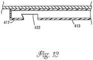
- Fig. 12shows another catheter 400 having features that are examples.
- the catheter 400includes a delivery sheath 116 positioned at one end and a recovery sheath 120 positioned at the opposite end.
- the delivery sheath 116 and the recovery sheath 120are interconnected by a central elongated member 410.
- the elongated member 410includes a solid shaft 411 connected to the recovery sheath 120, and a tubular shaft 413 connected to the delivery sheath 116.
- the tubular shaft 413defines a central lumen 415 that extends from a first end 417 of the tubular shaft to the delivery sheath 116.
- the lumenis preferably sealed so as to not be in fluid communication with the interior of the delivery sheath 116.
- the delivery sheath 116includes a guidewire port 148 and a host wire port 150.
- a balloonsuch as an angioplasty balloon or a low pressure occlusion balloon 419 is provided on the tubular shaft 413 adjacent to the delivery sheath 116.
- the balloon 419is in fluid communication with the lumen 415 of the tubular shaft 413.
- the first end 417 of the tubular shaft 413is sealed by a septum or other seal 421.
- the septum or seal 421can include multiple membranes 421a, 421b (see Fig. 12A ) bonded together at a perimeter of the membranes.
- the membrane 421 acan have a self-closing slit 425 while membrane 421b can have a central hole that seals against a blunt needle.
- Either membranecan have a rim 427 that can be sealed to lumen 415 of tubular shaft 413.
- a syringe with a blunt needlecan be used to inject fluid into the lumen through the seal 421 to inflate the balloon 419.
- the first end 417 of the tubular shaft 413can include a side port in fluid communication with a Luer fitting.
- the Luer fittingprovides a connection location for attaching an inflation device.
- Tuohy Borst fittingscan be secured to the tubular shaft at locations distal to and proximal to the side port to provide a seal between the Luer fitting and the catheter body.
- the Tuohy Borst fittingscan also referred to as hemostatic valves.
- a Luer lock fittingcan be used to provide fluid to the lumen 415.
- the tubular shaft 413can include an elongated slot 433 adjacent the first end in which a Luer lock fitting 435 (shown in Figs. 14 and 15 ) can be inserted.
- Fig. 14shows the Luer lock fitting 435 partially inserted within the slot 433.
- a stem 437 of the lock fitting 435fits within the lumen 415.
- the stem 437snugly fits within the lumen 415 such that friction between the stem 437 and the wall of the tubular shaft 413 function to provide a fluid tight seal about the stem 437.
- a rounded end 439 of the lock fitting 435also fits within the slot 433 such that the Luer fitting 435 snaps into a locked or seated position as shown in Fig. 15 .
- the Luer fitting 435provides an attachment location for attaching a balloon inflation apparatus to the catheter.
- Fig. 12could alternatively be positioned on the delivery sheath 116 of catheter 400 by those skilled in the art. See, for example, Fig. 12B .
- the catheter of Fig. 12Bcan be used in a manner that helps to prevent distal migration of emboli during embolic filter passage across a treatment site.
- the cathetercan be used as described for catheter 100 in connection with Figs. 3-7 .
- the catheteris preloaded with an actuator style embolic protection device such as that described in U.S. Patent No. 6,520,978 B1 .
- the catheter balloon 419Prior to crossing the treatment site, the catheter balloon 419 is inflated to a pressure sufficient to substantially impede blood flow across the treatment site. After balloon inflation, the guidewire 19 is withdrawn and the embolic filter is advanced across the treatment site in a collapsed diameter.
- emboli liberated by the embolic filter during treatment site passagecannot be transported distally because the inflated balloon 419 prevents distal blood flow and distal transport of emboli within the flow stream.
- the actuating style filteris actuated to cause it to diametrically enlarge and position the filter across the vessel cross sectional area.
- the balloon 419is deflated and flow is restored, causing emboli liberated during treatment site crossing to be transported to and captured by the filter.
- the cathetercan now be removed and the treatment site treated.
- the cathetercan be advanced and the balloon used to treat a lesion, followed by balloon deflation and capture of released emboli in the filter.
- the cathetercould include openings for delivering a substance (e. g. , a medicine, dye, or other substance) to the vasculature of a patient.
- a substancee. g. , a medicine, dye, or other substance
- Fig. 16illustrates a system 600 for protecting the delivery sheath 116 during shipping.
- the systemincludes an outer protective sheath 610 mounted over the exterior of the delivery sheath 116.
- a stylette 615extends into the tip of the delivery sheath 116, through the first sidewall port 148 and along the outer surface of the catheter.
- the styletteprovides rigidity for protecting the delivery sheath 116.
- a loop 620is provided for pulling the stylette 615 from the sheath 116.
- Fig. 17shows an alternative stylette 600'having a flag 650 as compared to a loop 620.
- Method of use instructions for the cathetercan be printed on the flag 650.
- the protective packagingcan be applied to the recovery sheath 120, or to both the delivery sheath 116 and the recovery sheath 120. It will be further appreciated that it is not necessary to utilize both a stylette and protective sheath; they can be used alone as well as in combination at either or both ends of the catheter.
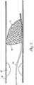
- FIG 18illustrates a catheter 700 according to the present invention and similar to the catheter of Figure 2 .
- the catheter 700includes a central shaft 710 having a first end 712 positioned opposite from a second end 714.
- a tip in the form of a flexible delivery sheath 716is positioned at the first end 712.
- the flexible delivery sheath 716defines an internal pocket 718 (i. e. , a compartment, cavity, enclosure, chamber or receptacle) configured for receiving a preloaded device (e. g. , a preloaded embolic protection device such as the filter device 770 shown in Fig. 18 ).
- the filter device 770includes an expandable filter mesh 771 secured to the distal end of a host wire 774.
- the catheter 700also includes a flexible retrieval sheath 720 positioned at the second end 714 of the shaft 710.
- the flexible retrieval sheath 720defines an internal pocket 722 sized and shaped for receiving a medical device (e. g., an embolic protection device such as the filter device 770 of Fig. 18 ) for retrieval of the medical device after the device has been used.
- a medical devicee. g., an embolic protection device such as the filter device 770 of Fig. 18
- the delivery sheath 716includes a first sidewall port 748 and a second sidewall port 750.
- the first and second sidewall ports 748, 750are spaced apart from one another along the length of the sheath 716.
- the first sidewall port 748is located closer to a free end of the sheath 716 than the second sidewall port 750.
- the ports 748,750are preferably skived and dimensioned to allow a distally and inwardly extending wire to extend from the outside of the sheath 716 to the internal pocket 718 at an angle of less than about 10 relative to a longitudinal axis of the catheter 700.
- the catheter 700includes a lumen portion 740 of a narrower diameter than the internal pocket 718.
- the diameter of the internal pocket 718is reduced at constriction 744.
- Constriction 744prevents proximal movement of the filter device 770 and creates a preloading stop or "holding zone" location for the filter device 770. This location is distal of the constriction 744 and proximal of the first sidewall port 748 to prevent interaction of the guidewire 719 with the filter 770.
- Figures 19 and 19Aillustrate a guide wire loading assist device 854.
- the device 854has a port 856 that lines up with sidewall port 748 of catheter 700.
- assist device 854bends catheter 700 to make loading of the guide wire 719 easier.
- the assist device 854bends catheter 700 by having a pre-formed shape and stiffness sufficient to overcome the shape and stiffness of catheter 700. Specifically, the device 854 ensures that the guide wire will exit the correct port without interacting with the filter 770.
- the device 854may be loaded prior to packaging or provided as a separate piece within the packaging for the physician to place on the catheter 700 prior to introducing the guide wire 719.
- a slit 858 that runs from port 856 to the proximal end of the device 854allows for easy removal of the device once the guide wire is in place.
- a slitmay run from port 856 to distal end of the device 854, or both proximal and distal slits may be provided.
- slotsare used rather than slits.
- a pull tab of a size sufficient for a device user to graspis provided at one or both ends of device 854 for the purpose of facilitating device 854 removal from catheter 700.
- the device 854is comprised of a polymer having bright color so as to facilitate rapid identification by the device user. After the device 854 is removed, the catheter reverts to its original conformation.
- the device 854preferably is made of a heat formable material formed with a slight bend. Suitable heat formable materials include polymers such as LDPE, MDPE, and PEBAX. The device 854 can also be injection molded.
- Figures 19B and 19Cillustrate an alternate embodiment of a guide wire loading assist device 854.
- the device 854has a port 856 that lines up with sidewall port 748 of catheter 700.
- assist device 854bends catheter 700 to make loading of the guide wire 719 easier.
- the assist device 854bends catheter 700 by having a pre-formed shape and stiffness sufficient to overcome the shape and stiffness of catheter 700. Specifically, the device 854 ensures that the guide wire will exit the correct port without interacting with the filter 770.
- the device 854may be loaded prior to packaging or provided as a separate piece within the packaging for the physician to place on the catheter 700 prior to introducing the guide wire 719.
- a slit 958runs from port 856 to the distal end of the device 854 and allows for easy removal of the device once the guide wire is in place.
- a slotruns from a location proximal to port 856 to a proximal end of the device 854.
- the axis of proximal slotted end of device 854is oriented approximately 25° away from the axis of the device 854 in the region of port 856.
- the proximal slotted end of device 854functions as a pull tab of a size sufficient for a device user to grasp for removal of device 854 from catheter 700.
- the device 854is comprised of a polymer having bright color so as to facilitate rapid identification by the device user. After the device 854 is removed, the catheter reverts to its original conformation.
Landscapes
- Health & Medical Sciences (AREA)
- Life Sciences & Earth Sciences (AREA)
- Veterinary Medicine (AREA)
- Public Health (AREA)
- Engineering & Computer Science (AREA)
- General Health & Medical Sciences (AREA)
- Biomedical Technology (AREA)
- Heart & Thoracic Surgery (AREA)
- Animal Behavior & Ethology (AREA)
- Hematology (AREA)
- Anesthesiology (AREA)
- Pulmonology (AREA)
- Biophysics (AREA)
- Cardiology (AREA)
- Oral & Maxillofacial Surgery (AREA)
- Transplantation (AREA)
- Vascular Medicine (AREA)
- Surgical Instruments (AREA)
- Materials For Medical Uses (AREA)
Description
- This application claims the benefit of
U.S. Provisional Application No. 60/458,884, filed March 28, 2003 U.S. Provisional Application No. 60/508,437, filed October 3, 2003 - The present invention is related generally to medical devices. More specifically, the present invention is related to intravascular medical devices such as catheters and guidewires.
- Blood vessel disease is a significant cause of premature disability and death. Heart attacks, strokes and other ailments are often caused by blood vessel disease.
- The most common disease of the blood vessels is atherosclerosis. Atherosclerosis involves the accumulation of plaques of cholesterol, lipids and cellular debris within an artery. As the plaque accumulates, the artery wall thickens thereby narrowing the lumen of the artery. As the lumen narrows, the blood flow to tissue nourished by the artery is diminished. The development of plaques can also contribute to the formation of emboli or thrombi. An embolus is a moving obstruction such as a platelet aggregate. A thrombus can be a fixed obstruction such as a wall adherent blood clot or can become an embolus. A thrombus or embolus within a coronary artery can occlude the artery thereby causing myocardial infarction, angina and other conditions. A blockage caused by a thrombus or embolus within a vessel supplying blood to the brain can lead to a stroke. Renal, peripheral, and other blood vessels can also become blocked by an embolus or a thrombus thereby causing tissue damage downstream of the blockage.
- A number of medical procedures have been developed to allow for the removal of plaque from vessel walls or to clear a channel through plaque, thrombus or clot to restore blood flow. For example, atherectomy or thrombectomy devices can be used to remove atheroma or thrombus. Vessel restrictions can also be treated with grafts that bypass the restrictions. Alternatively, balloon angioplasty and stenting procedures can be used to enlarge the lumen size of a vessel at an obstruction.
- In a typical angioplasty procedure, a guide wire and guide catheter are inserted into a vessel of a patient. An inflatable balloon is then pushed through the guide catheter and advanced across a stenosis or blockage. Once positioned at the blockage, the balloon is inflated to dilate the blockage and open a flow channel through the partially blocked vessel region. One or more stents may also be placed across the dilated region or regions to reinforce the expanded vessel segment or to maintain dilatation of a vessel segment.
- While some stenoses remain adherent to the vessel wall during treatment, others are more brittle, and may partially crack and fragment during treatment, allowing the fragments to flow downstream where they may block more distal and smaller vessels. Consequences of embolization include myocardial infarction, stroke, diminished renal function, and impairment of peripheral circulation possibly leading to pain and amputation.
- Embolic protection devices have been developed to prevent the downstream travel of materials such as thrombi, grumous, emboli, and plaque fragments. Devices include occlusive devices and filters and may be deployed distal to a treatment site or proximal to a treatment site. Occlusive devices, for example distal inflatable balloon devices, can totally block fluid flow through the vessel. The material trapped by the inflatable devices can remain in place until removed using a method such as aspiration. Occlusive devices can also be deployed proximal to a treatment site and flow reversed or stopped at the treatment site. Following treatment emboli are carried by flow out of the vessel typically through a catheter and out of a patient. Filters can allow perfusing blood flow during the emboli capture process. The filters can be advanced downstream of a site to be treated and expanded to increase the filter area.
- Emboli, such as grumous or atheroma fragments, can be captured in the filter until the procedure is complete or the filter is occluded. When the capacity of the filter is reached, the filter may then be retracted and replaced.
- Embolic protection devices can be delivered over guide wires and within guide catheters. The embolic protection methods are normally practiced ancillary to another medical procedure, for example angioplasty with stenting or atherectomy. The embolic protection procedure typically protects downstream regions from emboli resulting from practicing the therapeutic interventional procedure.
EP0761250A describes a bi-directional catheter for insertion into a body lumen.- One inventive aspect of the present disclosure relates to a medical device as further disclosed in claim 1, comprising an elongated member configured to be advanced along a vascular path of a patient, the elongated member having opposite first and second ends and corresponding first and second end portions, the first end and second ends both being adapted for intravascular insertion, and the elongated member having a length defined between the first and second ends, the first end portion comprising a delivery sheath and the second end portion comprising a retrieval sheath, defining an internal pocket, the delivery sheath comprising first and second sidewall ports adapted for receiving wires, the first sidewall port being located closer to a free end of the sheath than the second sidewall port, the elongated member further comprising a lumen between the first and second sidewall ports, the lumen having a narrower diameter than the internal pocket provided by a constriction. The elongated member has sufficient flexibility to be advanced through a human vasculature. Preferably, the first and second ends are adapted to have different operating characteristics.
- Depending on the operating characteristics needed for a particular procedure, a physician can insert either the first end portion or the second end portion of the elongated member into the patient's vasculature. The intravascular medical device can include any number of different types of devices used in the treatment of vascular disease. Example devices include guide wires, catheters, embolic protection device delivery systems and embolic protection device retrieval systems.
- It is to be understood that both the foregoing general description and the following detailed description are exemplary and explanatory and are intended to provide further explanation of the invention as claimed.
FIG. 1 schematically shows a medical device having features that are examples.FIG. 2 shows a double-ended catheter having features that are examples.FIG. 3 shows the catheter ofFIG. 2 with a delivery end of the catheter containing an emboli protection device, the delivery end is located adjacent to an ostium.FIG. 4 shows the delivery end of the catheter ofFIG. 2 at a target site.FIG. 5 shows the emboli protection device ofFIGS. 3 and4 deployed at the target site.FIG. 6 shows the catheter ofFIG. 2 with a retrieval end of the catheter in close proximity to the deployed emboli protection device ofFIG. 5 .FIG. 7 shows the emboli protection device ofFIG. 6 captured within the retrieval end of the catheter ofFIG. 2 .FIG. 8 shows an alternative double-ended catheter.FIG. 9 is a cross-sectional view taken along section line 9-9 ofFIG. 8 .FIG. 10 shows another alternative double-ended catheter.FIG. 11 is a cross-sectional view taken along section line 11-11 ofFIG. 10 .FIG. 12 shows a double-ended catheter that includes an expandable balloon.FIG. 12A is a detailed view of a portion ofFIG. 12 .FIG. 12B is an alternative balloon catheter configuration.FIGS. 13-15 show a technique for equipping the catheter ofFIG. 12 with a Luer fitting for use in inflating and deflating the expandable balloon.FIGS. 16 and 17 show packaging techniques for protecting the delivery end of the catheter ofFIG. 2 during shipping.FIG. 18 shows a double-ended catheter in accordance with the present invention.FIGS. 19 and 19A show a guide wire loading assist device disposed on the double-ended catheter.FIGS. 19B and 19C show an alternate embodiment of a guide wire loading assist device.- Inventive aspects of the present disclosure relate to intravascular medical devices having opposite end portions each adapted for insertion within the vasculature of a patient. The opposite end portions each have different operating characteristics such that the medical device is capable of performing different functions depending upon the end of the device that is inserted into the patient. It will be appreciated that the broad aspects of the present invention are applicable to any number of different types of intravascular medical devices. Example devices include guide wires, catheters, implant delivery systems, emboli protection device delivery systems, implant retrieval systems, and emboli protection device retrieval systems.
- With reference now to the various drawing figures in which identical elements are numbered identically throughout, a description is provided of embodiments that are examples of how inventive aspects in accordance with the principles of the present invention may be practiced. It will be appreciated that the depicted embodiments are merely exemplary, and are not intended to limit the broad scope of the present invention.
Fig. 1 illustrates an intravascularmedical device 20 having features that are examples. It will be appreciated that the intravascularmedical device 20 can be embodied in a number of different devices such as catheters, guide wires, embolic filter delivery devices, embolic filter retrieval devices, as well as other devices.- Referring to
Fig. 1 , themedical device 20 includes anelongated body 22 having first and secondopposite end portions elongated body 22 is preferably sufficiently flexible to allow the device to be advanced through a curving vascular pathway without kinking and without puncturing the vessel wall. The first andsecond end portions elongated member 22 through the vasculature depending upon the direction theelongated member 22 is inserted into the vasculature. The first andsecond end portions first end portion 24 can be more flexible than thesecond end portion 26. The first andsecond end portions medical device 20 along different intravascular pathways. The first andsecond end portions first end portion 24 can be adapted for deploying an indwelling medical device such as a stent, graft or embolic protection device, and thesecond end portion 26 can be adapted for retrieving an indwelling medical device such as a stent, graft or embolic protection device. - The
elongated member 22 of themedical device 20 includes amain body 28 that extends between the first andsecond end portions main body 28 can have any number of different types of configurations. For example, themain body 28 can have a solid configuration such as a solid wire configuration, a solid polymeric configuration, or a composite metal and polymeric configuration. Theelongated member 22 can have a tubular configuration defining a single lumen, or can define a plurality of lumens. Themain body 28 includes a metal having "super elastic"properties such as nitinol. Themain body 28 can also include materials such as carbon fiber and its composites, liquid crystal polymers, ceramics, and composites in general. The elongated member may be coated with hydrophobic, hydrophilic, or biologically active coatings such as poly vinyl pyrrolidone coatings, ePTFE coatings, or heparin coatings. Theelongated member 22 has a length L in the range of 60-300 cm, and an outer diameter D in the range of 0. 013" to 0. 100" (0.033 to 0.25 cm). - The
end portions end portions end portions end portions second end portions main body 28, or can be separate pieces or components that are affixed to themain body 28. It will be appreciated that the lengths and diameters of theend portions end portions main body 28, and different flexibilities from one another. Figure 2 illustrates acatheter 100 having features that are examples. Thecatheter 100 includes acentral shaft 110 having afirst end 112 positioned opposite from asecond end 114. A tip in the form of aflexible delivery sheath 116 is positioned at thefirst end 112. Theflexible delivery sheath 116 defines an internal pocket 118 (i. e., a compartment, cavity, enclosure, chamber or receptacle) configured for receiving a preloaded device (e. g., a preloaded embolic protection device such as thefilter device 70 shown inFigs. 3-5 ). Thecatheter 100 also includes aflexible retrieval sheath 120 positioned at thesecond end 114 of theshaft 110. Theflexible retrieval sheath 120 defines aninternal pocket 122 sized and shaped for receiving a medical device (e. g., an embolic protection device such as thefilter device 70 ofFigs. 3-5 ) for retrieval of the medical device after the device has been used.- The
shaft 110 of thecatheter 100 is preferably sufficiently flexible and has sufficient column strength to be advanced through the vasculature of a patient. Theshaft 110 includes a solid wire coated with an outer layer of a polymeric material. However, it will be appreciated that in other embodiments, the shaft could include a tubular metal configuration or other configurations. Theshaft 110 can have a length in the range of 70-170 cm, and more preferably in the range of 100-140 cm.
Theshaft 110 can have an outer diameter D in the range of 0.026"-0. 040" (0.066-0. 10 cm). - Referring still to
Fig. 2 , thedelivery sheath 116 of the catheter preferably includes a material that is softer and more pliable than thecentral shaft 110. The flexible design of thedelivery sheath 116 facilitates advancing thecatheter 100 through tortuous vessels while the more rigidcentral shaft 110 can provide pushability. Thedelivery sheath 116 is formed of a polymer such as LDPE, MDPE, or PEBAX. The outer diameter of the delivery sheath can be in the range of 0.026-0. 040 inches (0.066-0. 10 cm), a wall thickness of the delivery sheath can be in the range of 0.001 to 0.005 inches (0.0025 to 0.013 cm), and a length of the delivery sheath can be in the range of 10 to 40 centimeters. - Referring still to
Fig. 2 , thedelivery sheath 116 includes afirst sidewall port 148 and asecond sidewall port 150. The first andsecond sidewall ports sheath 116. - The
first sidewall port 148 is located closer to a free end of thesheath 116 than thesecond sidewall port 150. Theports sheath 116 to theinternal pocket 118 at an angle of less than about 10 relative to a longitudinal axis of thecatheter 100. Further details regarding the configuration of the flexible sheath can be found inU. S. Patent Application Publication No. 2003/0233117 A1, published December 18, 2003 , entitled RAPID EXCHANGE CATHETERS USABLE WITH EMBOLIC PROTECTION DEVICES. - The
recovery sheath 120 of thecatheter 100 is preferably made of a compliant material that is more flexible than theshaft 110. Preferably, thesheath 120 has sufficient flexibility to allow thesheath 120 to traverse the tortuous pathways typically encountered within the vasculature of a human. - Suitable materials for making the
sheath 120 include thermal plastic polymers, polymer blends and thermal set polymers such as silicone, or silicone blends with a low durometer. One such material is a 35140 D PEBAX blend. Any other appropriate compliant materials may, however, be used. In one embodiment, the outer diameter of the recovery sheath can be in the range of 0.040-0. 060 inches (0.10 to 0.15 cm), a wall thickness of the recovery sheath can be in the range of 0.001 to 0.005 inches (0.0025 to 0.013 cm), and a length of the recovery sheath can be in the range of 5 to 30 centimeters. - Referring still to
Fig. 2 , the recovery sheath has an outermost end that forms a rolledtip 132. The rolledtip 132 is especially designed for crossing a stented or otherwise constricted region of a blood vessel. The rolledtip 132 can also function to capture an implanted device such as an embolic protection device. Further details regarding therecovery sheath 120 can be found inU. S. Patent Application Publication No. 2002/0111649 A1, published August 15, 2002 , entitled ROLLED TIP RECOVERY CATHETER. - The sheaths 116,120 can include one or more bands of radiopaque material, or can be filled with radiopaque material. Examples of radiopaque materials include barium sulfate, bismuth sub carbonate, tungsten powder, and the like. The presence of radiopaque materials facilitates viewing the sheaths under fluoroscopy. The sheaths 116,120 may be coated with hydrophobic, hydrophilic, or biologically active coatings such as poly vinyl pyrrolidone coatings, ePTFE coatings, or heparin coatings.
- Use of the
catheter 100 will now be described with respect to a coronary procedure. However, it will be appreciated that thecatheter 100 can also be used for treating other vessels (e. g. , carotid, renal, peripheral, and other blood vessels). - In an example of a coronary procedure, a physician first inserts a guidewire (not shown) into the femoral artery of a patient near the groin, and advances the guidewire through the artery, over the aorta and to a
coronary ostium 21. Once the guidewire is in place, aguide catheter 11 is passed over the guidewire and advanced until a distal end of theguide catheter 11 is located adjacent thecoronary ostium 21. The guidewire (not shown) is then removed.
With theguide catheter 11 in place, acoronary guidewire 19 is inserted into the guide catheter and advanced into the coronary artery. SeeFig. 3 . Next, the proximal end of thecoronary guidewire 19 is inserted (i.e. back-loaded) through the distal opening ofsheath 116 and then thefirst sidewall port 148 of thedelivery catheter 100. - Prior to insertion of the
coronary guidewire 19 through thefirst sidewall port 148, an embolic protection device such as anembolic filter device 70 is preferably pre-loaded within thedelivery sheath 116 of thecatheter 100. Thefilter device 70 is preferably a self-expandable filter device such as the filter device disclosed inU.S. Patent No. 6,325,815 . Thefilter device 70 includes anexpandable filter mesh 71 secured to the distal end of ahost wire 74. As shown inFig. 3 , in the pre-loaded configuration, the mesh of the filter device is compressed in a radially reduced profile configuration within thedelivery sheath 116, and thehost wire 74 extends from the mesh material through thesecond sidewall port 150 of thedelivery sheath 116. Thefilter device 70 can be viewed as one type of distal emboli protection element. Other distal protection elements which can be included as part of the device are occlusive emboli protection elements, including expandable or inflatable elements for blocking fluid flow through a vessel. - After the
guide wire 19 has been back-loaded through thedelivery sheath 116, thedelivery sheath 116 of thecatheter 100 is advanced through theguide catheter 11 along theguidewire 19 until thedelivery sheath 116 is advanced to the distal tip theguide catheter 11, as shown inFig. 3 . Preferably, theguidewire 19 is then further advanced within the coronary artery to a point where the distal most tip of theguidewire 19 is located at atarget site 25 within a coronary artery 23 (e.g., a site located downstream of a treatment site such as an occlusion 27). Thedelivery sheath 116 of thecatheter 100 can then be tracked along theguide wire 19 to thetarget site 25 as shown inFig. 4 . In other methods, theguidewire 19 and thecatheter 100 can be advanced together across the target site with theguidewire 19 providing stiffening for thecatheter 100. - Once the tip of the
delivery sheath 116 is located at thetarget site 25, theguidewire 19 is retracted proximally through thedistal sidewall port 148. With the guidewire no longer present within thedelivery sheath 116, thefilter device 70 can be distally advanced to the tip of thedelivery sheath 116 and then from thedelivery sheath 116. For example, theembolic filter 70 can be advanced from thesheath 116 by proximally retracting thecatheter 100 while thehost wire 74 is held in place by the treating physician. By retracting thecatheter 100, thesheath 116 retracts relative to thefilter device 70 thereby exposing thefilter device 70 and allowing thefilter device 70 to expand radially so as to provide filtration across the entire cross sectional area of the vessel as shown inFig. 5 . - Once the
filter device 70 is in place, thecatheter 100 can be retracted from the patient, and an interventional device (e.g., a balloon angioplasty catheter, a stent delivery catheter, an atherectomy device, a thrombectomy device or any other device) can be introduced over thehost wire 74 and used to treat the treatment site. As the treatment site is treated, any emboli generated during the treatment process are captured by thefilter 70. - After the treatment process has been completed, the interventional device is removed and the
catheter 100 is reintroduced over thehost wire 74. However, when reintroduced, thecatheter 100 is reversed such that therecovery sheath 120 functions as the distal most tip of thecatheter 100. Preferably, thehost wire 74 is passed through the interior of therecovery sheath 120 as shown inFig. 6 . Thecatheter 100 is advanced until therolled end 132 is positioned immediately proximal to thefilter device 70. Thehost wire 74 is then pulled in a proximal direction causing a proximal end of thefilter device 70 to contact the rolledtip 132. As thefilter device 70 contacts the rolledtip 132, the rolledtip 132 is urged elastically toward an open orientation in which thefilter device 70 can be passed into therecovery sheath 120. Once thefilter device 70 has been fully drawn into thesheath 120 as shown inFig. 7 , the rolledtip 132 reaches a point where it ceases to be engaged by thefilter device 70, and it elastically returns to its undeflected configuration. It will be appreciated that the resilient material forming thesheath 120 prevents the escape of emboli when thefilter device 70 is captured. Preferably, at least a portion of the wall of thesheath 120 closely encompasses the periphery of thefilter device 70 and assumes the shape of the periphery. As a result, emboli are prevented from passing between the periphery of thefilter device 70 and the wall of thesheath 120. Alternatively, thefilter device 70 can be partly drawn into therecovery sheath 120 such that only the enlarged proximal opening of the filter is within the sheath. - Once the filter device is positioned within the
recovery sheath 120, both thehost wire 74 and thecatheter 100 can be withdrawn from the patient together as a unit. Thereafter, the procedure is completed by removing theguide catheter 22 from the patient. Figs. 8 and 9 illustrate analternative catheter 200 having a similar configuration as thecatheter 100 ofFig. 2 , except the solidcentral shaft 110 has been replaced with adouble lumen configuration 210 having afirst end 212 and asecond end 214. Thecatheter 200 includes adelivery sheath 116 positioned at thefirst end 212 and arecovery sheath 120 positioned at thesecond end 114. Thedouble lumen configuration 210 includes afirst tube 211 that is coaxial with thedelivery sheath 116, and asecond tube 213 that is coaxial with therecovery sheath 120. It will be appreciated that the tubes of thedouble lumen configuration 210 are coupled together and are sufficiently flexible to be able to be passed through a tortuous vascular pathway, and also have sufficient column stiffness to allow thecatheter 200 to be pushed through the vasculature. It will be appreciated that the tubes can be manufactured using any number of known techniques. For example, the tubular structures may be extruded or coextruded in the cross sectional shape shown infigure 9 or in any number of alternative cross sections, for example those known in the art as double D, smile, or other configurations. Alternatively, the tubular structures can be manufactured from individual tubes of polymer such as polyimide or a super elastic material such as nitinol and held together with adhesives or a thin tube that surrounds both single lumen tubes. It will be appreciated that any number of different types of material can be used to formdouble lumen configuration 210.- The
catheter 200 can be used to both deliver a device such as an embolic protection device, and to retrieve a device such as an embolic protection device. Thecatheter 200 is used in a manner similar to thecatheter 100, except thecatheter 200 does not have rapid exchange capabilities. Instead, when thecatheter 200 is used with thedelivery sheath 116 as the distal end, a guidewire is passed through the entire length of thefirst tube 211. Similarly, when theretrieval sheath 120 is used as the distal end of thecatheter 200, a guidewire or wire such ashost wire 74 is passed completely through thesecond tube 213 of thedouble lumen configuration 210. Figs. 10 and 11 illustrate anothercatheter 300 having features that are in accordance with the principles of the present disclosure. Similar to the previous embodiments, thecatheter 300 includes adelivery sheath 116 positioned at one end, and arecovery sheath 120 positioned at the opposite end. Thedelivery sheath 116 and therecovery sheath 120 are interconnected by an elongatedcentral structure 310 that includes asolid shaft 350 coupled to atubular shaft 352. Thesolid shaft 350 is connected to therecovery sheath 120, and thetubular shaft 352 is connected to thedelivery sheath 116. The elongated central structure is sufficiently flexible to bend through the contours of a tortuous vascular pathway, and also include sufficient column strength to allow thecatheter 300 to be pushed through the pathway. Thetubular shaft structure 352 has a central lumen in fluid communication with thepocket 118 of thedelivery sheath 116.- It will be appreciated that the
catheter 300 can be used to deliver devices such as embolic protection devices in much the same way as the previous two embodiments. However, when delivering an embolic protection device using thedelivery sheath 116, thedelivery sheath 116 as well as the entiretubular shaft 352 would typically be passed over a guidewire. In contrast, when thecatheter 300 is used as a retrieval device, thecatheter 300 can be used as a rapid exchange catheter in which a guidewire or wire is not passed through the entire catheter, but instead only passes through the distal tip (e. g. , therecovery sheath portion 120 of the catheter). Fig. 12 shows anothercatheter 400 having features that are examples. Thecatheter 400 includes adelivery sheath 116 positioned at one end and arecovery sheath 120 positioned at the opposite end. Thedelivery sheath 116 and therecovery sheath 120 are interconnected by a centralelongated member 410. Theelongated member 410 includes asolid shaft 411 connected to therecovery sheath 120, and atubular shaft 413 connected to thedelivery sheath 116. Thetubular shaft 413 defines acentral lumen 415 that extends from afirst end 417 of the tubular shaft to thedelivery sheath 116. The lumen is preferably sealed so as to not be in fluid communication with the interior of thedelivery sheath 116. Thedelivery sheath 116 includes aguidewire port 148 and ahost wire port 150.- Referring still to
Fig. 12 , a balloon such as an angioplasty balloon or a lowpressure occlusion balloon 419 is provided on thetubular shaft 413 adjacent to thedelivery sheath 116. Theballoon 419 is in fluid communication with thelumen 415 of thetubular shaft 413. Thefirst end 417 of thetubular shaft 413 is sealed by a septum orother seal 421. The septum or seal 421 can includemultiple membranes Fig. 12A ) bonded together at a perimeter of the membranes. Themembrane 421 a can have a self-closing slit 425 whilemembrane 421b can have a central hole that seals against a blunt needle. Either membrane can have arim 427 that can be sealed to lumen 415 oftubular shaft 413. A syringe with a blunt needle can be used to inject fluid into the lumen through theseal 421 to inflate theballoon 419. - Other techniques can also be used to provide fluid into the lumen. For example, the
first end 417 of thetubular shaft 413 can include a side port in fluid communication with a Luer fitting. The Luer fitting provides a connection location for attaching an inflation device. Tuohy Borst fittings can be secured to the tubular shaft at locations distal to and proximal to the side port to provide a seal between the Luer fitting and the catheter body. The Tuohy Borst fittings can also referred to as hemostatic valves. - Additionally, a Luer lock fitting can be used to provide fluid to the
lumen 415. For example, as shown inFig. 13 , thetubular shaft 413 can include anelongated slot 433 adjacent the first end in which a Luer lock fitting 435 (shown inFigs. 14 and15 ) can be inserted.Fig. 14 shows the Luer lock fitting 435 partially inserted within theslot 433. Astem 437 of the lock fitting 435 fits within thelumen 415. Preferably, thestem 437 snugly fits within thelumen 415 such that friction between thestem 437 and the wall of thetubular shaft 413 function to provide a fluid tight seal about thestem 437. Arounded end 439 of the lock fitting 435 also fits within theslot 433 such that the Luer fitting 435 snaps into a locked or seated position as shown inFig. 15 . The Luer fitting 435 provides an attachment location for attaching a balloon inflation apparatus to the catheter. - It should also be appreciated that the balloon shown in
Fig. 12 could alternatively be positioned on thedelivery sheath 116 ofcatheter 400 by those skilled in the art. See, for example,Fig. 12B . - The catheter of
Fig. 12B can be used in a manner that helps to prevent distal migration of emboli during embolic filter passage across a treatment site. For example, the catheter can be used as described forcatheter 100 in connection withFigs. 3-7 . However, the catheter is preloaded with an actuator style embolic protection device such as that described inU.S. Patent No. 6,520,978 B1 . Prior to crossing the treatment site, thecatheter balloon 419 is inflated to a pressure sufficient to substantially impede blood flow across the treatment site. After balloon inflation, theguidewire 19 is withdrawn and the embolic filter is advanced across the treatment site in a collapsed diameter. - Importantly, emboli liberated by the embolic filter during treatment site passage cannot be transported distally because the
inflated balloon 419 prevents distal blood flow and distal transport of emboli within the flow stream. After crossing the treatment site, the actuating style filter is actuated to cause it to diametrically enlarge and position the filter across the vessel cross sectional area. At this point, theballoon 419 is deflated and flow is restored, causing emboli liberated during treatment site crossing to be transported to and captured by the filter. The catheter can now be removed and the treatment site treated. Alternatively, the catheter can be advanced and the balloon used to treat a lesion, followed by balloon deflation and capture of released emboli in the filter. - While a balloon has been shown, it will be appreciated that the catheter could include openings for delivering a substance (e. g. , a medicine, dye, or other substance) to the vasculature of a patient.
Fig. 16 illustrates asystem 600 for protecting thedelivery sheath 116 during shipping. The system includes an outerprotective sheath 610 mounted over the exterior of thedelivery sheath 116. Astylette 615 extends into the tip of thedelivery sheath 116, through thefirst sidewall port 148 and along the outer surface of the catheter. The stylette provides rigidity for protecting thedelivery sheath 116. Aloop 620 is provided for pulling the stylette 615 from thesheath 116.Fig. 17 shows an alternative stylette 600'having aflag 650 as compared to aloop 620. Method of use instructions for the catheter can be printed on theflag 650.- Alternatively the protective packaging can be applied to the
recovery sheath 120, or to both thedelivery sheath 116 and therecovery sheath 120. It will be further appreciated that it is not necessary to utilize both a stylette and protective sheath; they can be used alone as well as in combination at either or both ends of the catheter. Figure 18 illustrates acatheter 700 according to the present invention and similar to the catheter ofFigure 2 . Thecatheter 700 includes acentral shaft 710 having afirst end 712 positioned opposite from asecond end 714. A tip in the form of aflexible delivery sheath 716 is positioned at thefirst end 712. Theflexible delivery sheath 716 defines an internal pocket 718 (i. e. , a compartment, cavity, enclosure, chamber or receptacle) configured for receiving a preloaded device (e. g. , a preloaded embolic protection device such as thefilter device 770 shown inFig. 18 ). Thefilter device 770 includes anexpandable filter mesh 771 secured to the distal end of ahost wire 774. Thecatheter 700 also includes aflexible retrieval sheath 720 positioned at thesecond end 714 of theshaft 710. Theflexible retrieval sheath 720 defines aninternal pocket 722 sized and shaped for receiving a medical device (e. g., an embolic protection device such as thefilter device 770 ofFig. 18 ) for retrieval of the medical device after the device has been used.- The
delivery sheath 716 includes afirst sidewall port 748 and asecond sidewall port 750. The first andsecond sidewall ports sheath 716. Thefirst sidewall port 748 is located closer to a free end of thesheath 716 than thesecond sidewall port 750. The ports 748,750 are preferably skived and dimensioned to allow a distally and inwardly extending wire to extend from the outside of thesheath 716 to theinternal pocket 718 at an angle of less than about 10 relative to a longitudinal axis of thecatheter 700. - The
catheter 700 includes alumen portion 740 of a narrower diameter than theinternal pocket 718. The diameter of theinternal pocket 718 is reduced atconstriction 744.Constriction 744 prevents proximal movement of thefilter device 770 and creates a preloading stop or "holding zone" location for thefilter device 770. This location is distal of theconstriction 744 and proximal of thefirst sidewall port 748 to prevent interaction of theguidewire 719 with thefilter 770. Figures 19 and 19A illustrate a guide wire loading assistdevice 854. Thedevice 854 has aport 856 that lines up with sidewallport 748 ofcatheter 700. As shown inFigure 19 , assistdevice 854 bendscatheter 700 to make loading of theguide wire 719 easier. In some embodiments theassist device 854 bendscatheter 700 by having a pre-formed shape and stiffness sufficient to overcome the shape and stiffness ofcatheter 700. Specifically, thedevice 854 ensures that the guide wire will exit the correct port without interacting with thefilter 770.- The
device 854 may be loaded prior to packaging or provided as a separate piece within the packaging for the physician to place on thecatheter 700 prior to introducing theguide wire 719. Aslit 858 that runs fromport 856 to the proximal end of thedevice 854 allows for easy removal of the device once the guide wire is in place. Alternatively, a slit may run fromport 856 to distal end of thedevice 854, or both proximal and distal slits may be provided. In some embodiments, slots are used rather than slits. In another embodiment a pull tab of a size sufficient for a device user to grasp is provided at one or both ends ofdevice 854 for the purpose of facilitatingdevice 854 removal fromcatheter 700. In some embodiments thedevice 854 is comprised of a polymer having bright color so as to facilitate rapid identification by the device user. After thedevice 854 is removed, the catheter reverts to its original conformation. - The
device 854 preferably is made of a heat formable material formed with a slight bend. Suitable heat formable materials include polymers such as LDPE, MDPE, and PEBAX. Thedevice 854 can also be injection molded. Figures 19B and 19C illustrate an alternate embodiment of a guide wire loading assistdevice 854. Thedevice 854 has aport 856 that lines up with sidewallport 748 ofcatheter 700. As shown inFigure 19 , assistdevice 854 bendscatheter 700 to make loading of theguide wire 719 easier. In some embodiments theassist device 854 bendscatheter 700 by having a pre-formed shape and stiffness sufficient to overcome the shape and stiffness ofcatheter 700. Specifically, thedevice 854 ensures that the guide wire will exit the correct port without interacting with thefilter 770.- The
device 854 may be loaded prior to packaging or provided as a separate piece within the packaging for the physician to place on thecatheter 700 prior to introducing theguide wire 719. Aslit 958 runs fromport 856 to the distal end of thedevice 854 and allows for easy removal of the device once the guide wire is in place. A slot runs from a location proximal toport 856 to a proximal end of thedevice 854. The axis of proximal slotted end ofdevice 854 is oriented approximately 25° away from the axis of thedevice 854 in the region ofport 856. The proximal slotted end ofdevice 854 functions as a pull tab of a size sufficient for a device user to grasp for removal ofdevice 854 fromcatheter 700. In some embodiments thedevice 854 is comprised of a polymer having bright color so as to facilitate rapid identification by the device user. After thedevice 854 is removed, the catheter reverts to its original conformation. - The above description and the drawings are provided for the purpose of describing embodiments of the invention and are not intended to limit the scope of the invention in any way. It will be apparent to those skilled in the art that various modifications and variations can be made without departing from the scope of the invention. Thus, it is intended that the present invention cover the modifications and variations of this invention provided they come within the scope of the appended claims and their equivalents.
Claims (9)
- A medical device comprising:an elongated member configured to be advanced along a vascular path of a patient, the elongated member having opposite first and second ends (712, 714) and corresponding first and second end portions, the first end and second ends both being adapted for intravascular insertion, the first end having a different structure than the second end, the elongated member having a length defined between the first and second ends, the first end portion comprising a deliver sheath (716) defining an internal pocket (718) configured for receiving a preloaded device, and the second end portion comprising a retrieval sheath (720) defining an internal pocket (722), sized and shaped for receiving a medical device, the delivery sheath (716) comprising first and second sidewall ports (748, 750) adapted for receiving wires, the first sidewall port (748) being located closer to a free end of the sheath (716) than the second sidewall port (750), the elongated member further comprising a lumen portion (740) between the first and second sidewall ports, the lumen portion (740) having a narrower diameter than the internal pocket (718) wherein the diameter of the internal pocket (718) is reduced at constriction (744).
- The medical device of claim 1, wherein the first and second ends (712, 714) have different flexibilities.
- The medical device of claim 1 or claim 2, wherein the elongated member comprises a catheter (700).
- The medical device of any one of the preceding claims, wherein the first and second side wall ports (748, 750) are skived.
- The medical device of claim 4, wherein the retrieval sheath (720) comprises a rolled tip.
- An assembly comprising a guide wire and a medical device of any one of the preceding claims.
- An assembly comprising an embolic protection device and a medical device of any one of claims 1 to 5.
- An assembly of claim 7, further comprising a guide wire.
- An assembly of claim 7 or claim 8, wherein the embolic protection device is adapted to be delivered and retrieved by the elongate member.
Applications Claiming Priority (5)
| Application Number | Priority Date | Filing Date | Title |
|---|---|---|---|
| US45888403P | 2003-03-28 | 2003-03-28 | |
| US458884P | 2003-03-28 | ||
| US50843703P | 2003-10-03 | 2003-10-03 | |
| US508437P | 2003-10-03 | ||
| PCT/US2004/009518WO2004087018A2 (en) | 2003-03-28 | 2004-03-26 | Double ended intravascular medical device |
Publications (2)
| Publication Number | Publication Date |
|---|---|
| EP1608295A2 EP1608295A2 (en) | 2005-12-28 |
| EP1608295B1true EP1608295B1 (en) | 2017-05-03 |
Family
ID=33135117
Family Applications (1)
| Application Number | Title | Priority Date | Filing Date |
|---|---|---|---|
| EP04758510.4AExpired - LifetimeEP1608295B1 (en) | 2003-03-28 | 2004-03-26 | Double ended intravascular medical device |
Country Status (3)
| Country | Link |
|---|---|
| US (5) | US7637920B2 (en) |
| EP (1) | EP1608295B1 (en) |
| WO (1) | WO2004087018A2 (en) |
Families Citing this family (106)
| Publication number | Priority date | Publication date | Assignee | Title |
|---|---|---|---|---|
| US6575997B1 (en) | 1999-12-23 | 2003-06-10 | Endovascular Technologies, Inc. | Embolic basket |
| US6402771B1 (en) | 1999-12-23 | 2002-06-11 | Guidant Endovascular Solutions | Snare |
| US6660021B1 (en) | 1999-12-23 | 2003-12-09 | Advanced Cardiovascular Systems, Inc. | Intravascular device and system |
| US6540722B1 (en) | 1999-12-30 | 2003-04-01 | Advanced Cardiovascular Systems, Inc. | Embolic protection devices |
| US7918820B2 (en) | 1999-12-30 | 2011-04-05 | Advanced Cardiovascular Systems, Inc. | Device for, and method of, blocking emboli in vessels such as blood arteries |
| US6695813B1 (en) | 1999-12-30 | 2004-02-24 | Advanced Cardiovascular Systems, Inc. | Embolic protection devices |
| US6964670B1 (en) | 2000-07-13 | 2005-11-15 | Advanced Cardiovascular Systems, Inc. | Embolic protection guide wire |
| US6537294B1 (en) | 2000-10-17 | 2003-03-25 | Advanced Cardiovascular Systems, Inc. | Delivery systems for embolic filter devices |
| US6893451B2 (en) | 2000-11-09 | 2005-05-17 | Advanced Cardiovascular Systems, Inc. | Apparatus for capturing objects beyond an operative site utilizing a capture device delivered on a medical guide wire |
| US6506203B1 (en) | 2000-12-19 | 2003-01-14 | Advanced Cardiovascular Systems, Inc. | Low profile sheathless embolic protection system |
| US7044952B2 (en) | 2001-06-06 | 2006-05-16 | Sdgi Holdings, Inc. | Dynamic multilock anterior cervical plate system having non-detachably fastened and moveable segments |
| US7338510B2 (en) | 2001-06-29 | 2008-03-04 | Advanced Cardiovascular Systems, Inc. | Variable thickness embolic filtering devices and method of manufacturing the same |
| US6599307B1 (en) | 2001-06-29 | 2003-07-29 | Advanced Cardiovascular Systems, Inc. | Filter device for embolic protection systems |
| US6638294B1 (en) | 2001-08-30 | 2003-10-28 | Advanced Cardiovascular Systems, Inc. | Self furling umbrella frame for carotid filter |
| US6592606B2 (en) | 2001-08-31 | 2003-07-15 | Advanced Cardiovascular Systems, Inc. | Hinged short cage for an embolic protection device |
| US8262689B2 (en) | 2001-09-28 | 2012-09-11 | Advanced Cardiovascular Systems, Inc. | Embolic filtering devices |
| US7241304B2 (en) | 2001-12-21 | 2007-07-10 | Advanced Cardiovascular Systems, Inc. | Flexible and conformable embolic filtering devices |
| US6887258B2 (en) | 2002-06-26 | 2005-05-03 | Advanced Cardiovascular Systems, Inc. | Embolic filtering devices for bifurcated vessels |
| US7252675B2 (en) | 2002-09-30 | 2007-08-07 | Advanced Cardiovascular, Inc. | Embolic filtering devices |
| US7331973B2 (en) | 2002-09-30 | 2008-02-19 | Avdanced Cardiovascular Systems, Inc. | Guide wire with embolic filtering attachment |
| US20040088000A1 (en) | 2002-10-31 | 2004-05-06 | Muller Paul F. | Single-wire expandable cages for embolic filtering devices |
| US8591540B2 (en) | 2003-02-27 | 2013-11-26 | Abbott Cardiovascular Systems Inc. | Embolic filtering devices |
| EP1608295B1 (en) | 2003-03-28 | 2017-05-03 | Covidien LP | Double ended intravascular medical device |
| US7892251B1 (en) | 2003-11-12 | 2011-02-22 | Advanced Cardiovascular Systems, Inc. | Component for delivering and locking a medical device to a guide wire |
| US8092483B2 (en) | 2004-03-06 | 2012-01-10 | Medtronic, Inc. | Steerable device having a corewire within a tube and combination with a functional medical component |
| US7678129B1 (en) | 2004-03-19 | 2010-03-16 | Advanced Cardiovascular Systems, Inc. | Locking component for an embolic filter assembly |
| US8409237B2 (en)* | 2004-05-27 | 2013-04-02 | Medtronic, Inc. | Emboli filter export system |
| US8038696B2 (en)* | 2004-12-06 | 2011-10-18 | Boston Scientific Scimed, Inc. | Sheath for use with an embolic protection filter |
| ATE539789T1 (en) | 2005-02-18 | 2012-01-15 | Tyco Healthcare | QUICKLY REPLACEABLE CATHETER |
| US9259305B2 (en) | 2005-03-31 | 2016-02-16 | Abbott Cardiovascular Systems Inc. | Guide wire locking mechanism for rapid exchange and other catheter systems |
| US7938820B2 (en)* | 2005-08-18 | 2011-05-10 | Lumen Biomedical, Inc. | Thrombectomy catheter |
| US8021351B2 (en)* | 2005-08-18 | 2011-09-20 | Medtronic Vascular, Inc. | Tracking aspiration catheter |
| US20070073377A1 (en)* | 2005-09-27 | 2007-03-29 | Mcdonald Michael B | Method for placing a stent through a constricted lumen, and medical device |
| US20070083252A1 (en)* | 2005-09-27 | 2007-04-12 | Mcdonald Michael B | Method for placing a stent through a constricted lumen, and medical device |
| US8167902B2 (en)* | 2006-08-11 | 2012-05-01 | Tyco Healthcare Group Lp | Rapid exchange catheters for embolic protection devices |
| US8216209B2 (en) | 2007-05-31 | 2012-07-10 | Abbott Cardiovascular Systems Inc. | Method and apparatus for delivering an agent to a kidney |
| US7867273B2 (en) | 2007-06-27 | 2011-01-11 | Abbott Laboratories | Endoprostheses for peripheral arteries and other body vessels |
| US8070694B2 (en) | 2008-07-14 | 2011-12-06 | Medtronic Vascular, Inc. | Fiber based medical devices and aspiration catheters |
| US9636205B2 (en) | 2009-01-16 | 2017-05-02 | Claret Medical, Inc. | Intravascular blood filters and methods of use |
| US9326843B2 (en) | 2009-01-16 | 2016-05-03 | Claret Medical, Inc. | Intravascular blood filters and methods of use |
| US20170202657A1 (en) | 2009-01-16 | 2017-07-20 | Claret Medical, Inc. | Intravascular blood filters and methods of use |
| EP2387427B1 (en) | 2009-01-16 | 2014-08-27 | Claret Medical, Inc. | Intravascular blood filter |
| US8518073B2 (en) | 2009-01-29 | 2013-08-27 | Claret Medical, Inc. | Illuminated intravascular blood filter |
| US8974489B2 (en) | 2009-07-27 | 2015-03-10 | Claret Medical, Inc. | Dual endovascular filter and methods of use |
| US8876693B2 (en) | 2010-04-21 | 2014-11-04 | David Elliot Rapp | Device and method for vaginal sacrocolpopexy |
| US9101455B2 (en) | 2010-08-13 | 2015-08-11 | Cook Medical Technologies Llc | Preloaded wire for endoluminal device |
| CA2747610C (en) | 2010-08-13 | 2014-09-16 | Cook Medical Technologies Llc | Precannulated fenestration |
| US20130331735A1 (en)* | 2010-12-14 | 2013-12-12 | Henry W. Lupton | Interventional guidewire |
| US12150851B2 (en) | 2010-12-30 | 2024-11-26 | Claret Medical, Inc. | Method of isolating the cerebral circulation during a cardiac procedure |
| US9492264B2 (en) | 2010-12-30 | 2016-11-15 | Claret Medical, Inc. | Embolic protection device for protecting the cerebral vasculature |
| EP2522307B1 (en)* | 2011-05-08 | 2020-09-30 | ITSO Medical AB | Device for delivery of medical devices to a cardiac valve |
| US10779855B2 (en) | 2011-08-05 | 2020-09-22 | Route 92 Medical, Inc. | Methods and systems for treatment of acute ischemic stroke |
| EP4101399B1 (en) | 2011-08-05 | 2025-04-09 | Route 92 Medical, Inc. | System for treatment of acute ischemic stroke |
| US10485524B2 (en) | 2011-10-25 | 2019-11-26 | Essential Medical, Inc. | Instrument and methods for surgically closing percutaneous punctures |
| EP2601995B1 (en)* | 2011-12-07 | 2022-08-17 | CAR Holding B.V. | An arrangement for implementing kissing balloons for simulating a bifurcated vessel, a kit, a method of manufacturing the arrangement and a catheter provided with a buffer volume. |
| US9757104B2 (en) | 2012-07-19 | 2017-09-12 | Essential Medical, Inc. | Multi-lumen tamper tube |
| EP2732794A1 (en) | 2012-11-14 | 2014-05-21 | Contego AB | Improved embolic protection device and method |
| US20140236213A1 (en)* | 2013-02-15 | 2014-08-21 | BiO2 Medical, Inc. | Temporary filter retrieval apparatus and method |
| US10639019B2 (en) | 2013-03-15 | 2020-05-05 | Arrow International, Inc. | Vascular closure devices and methods of use |
| US9265512B2 (en) | 2013-12-23 | 2016-02-23 | Silk Road Medical, Inc. | Transcarotid neurovascular catheter |
| EP3858254B1 (en) | 2013-12-23 | 2024-04-24 | Teleflex Life Sciences LLC | Vascular closure device |
| US9820761B2 (en) | 2014-03-21 | 2017-11-21 | Route 92 Medical, Inc. | Rapid aspiration thrombectomy system and method |
| ES2975734T3 (en) | 2015-01-29 | 2024-07-12 | Becton Dickinson Co | Integrated Quick Insert Catheter |
| US10426497B2 (en) | 2015-07-24 | 2019-10-01 | Route 92 Medical, Inc. | Anchoring delivery system and methods |
| CN119949953A (en) | 2015-02-04 | 2025-05-09 | 92号医疗公司 | Intravascular access system, dilator and system including dilator |
| US11065019B1 (en) | 2015-02-04 | 2021-07-20 | Route 92 Medical, Inc. | Aspiration catheter systems and methods of use |
| US9566144B2 (en) | 2015-04-22 | 2017-02-14 | Claret Medical, Inc. | Vascular filters, deflectors, and methods |
| US10555727B2 (en) | 2015-06-26 | 2020-02-11 | Essential Medical, Inc. | Vascular closure device with removable guide member |
| US9821146B2 (en) | 2015-09-22 | 2017-11-21 | Abiomed, Inc. | Guidewire for cannula placement |
| US10639022B2 (en)* | 2015-11-03 | 2020-05-05 | W. L. Gore & Associates, Inc. | Endoscopic organ manipulation devices and methods |
| US10716915B2 (en) | 2015-11-23 | 2020-07-21 | Mivi Neuroscience, Inc. | Catheter systems for applying effective suction in remote vessels and thrombectomy procedures facilitated by catheter systems |
| US11197979B2 (en) | 2016-05-03 | 2021-12-14 | Access Flow Systems, Llc | Vascular access devices and methods |
| WO2017192702A1 (en)* | 2016-05-03 | 2017-11-09 | Access Flow Systems, Llc | Vascular access devices, systems, and methods |
| US11229445B2 (en) | 2016-10-06 | 2022-01-25 | Mivi Neuroscience, Inc. | Hydraulic displacement and removal of thrombus clots, and catheters for performing hydraulic displacement |
| CN110392591B (en) | 2017-01-10 | 2022-06-03 | 92号医疗公司 | Aspiration catheter system and method of use |
| US10864350B2 (en) | 2017-01-20 | 2020-12-15 | Route 92 Medical, Inc. | Single operator intracranial medical device delivery systems and methods of use |
| US11337790B2 (en) | 2017-02-22 | 2022-05-24 | Boston Scientific Scimed, Inc. | Systems and methods for protecting the cerebral vasculature |
| US10478535B2 (en)* | 2017-05-24 | 2019-11-19 | Mivi Neuroscience, Inc. | Suction catheter systems for applying effective aspiration in remote vessels, especially cerebral arteries |
| US11234723B2 (en) | 2017-12-20 | 2022-02-01 | Mivi Neuroscience, Inc. | Suction catheter systems for applying effective aspiration in remote vessels, especially cerebral arteries |
| US10668253B2 (en) | 2017-07-11 | 2020-06-02 | Teleflex Life Sciences Limited | Methods for exchanging devices |
| US11020224B2 (en) | 2017-07-11 | 2021-06-01 | Teleflex Life Sciences Limited | Methods for exchanging devices |
| EP3700464B1 (en) | 2017-10-27 | 2024-02-14 | Boston Scientific Scimed, Inc. | Systems for protecting the cerebral vasculature |
| US11154390B2 (en) | 2017-12-19 | 2021-10-26 | Claret Medical, Inc. | Systems for protection of the cerebral vasculature during a cardiac procedure |
| US11439491B2 (en) | 2018-04-26 | 2022-09-13 | Claret Medical, Inc. | Systems and methods for protecting the cerebral vasculature |
| JP7616642B2 (en) | 2018-05-17 | 2025-01-17 | ルート92メディカル・インコーポレイテッド | Suction catheter system and method of use |
| JP2021535778A (en) | 2018-08-21 | 2021-12-23 | ボストン サイエンティフィック サイムド, インコーポレイテッドBoston Scientific Scimed, Inc. | A system to protect the cerebrovascular system |
| WO2020102679A1 (en)* | 2018-11-15 | 2020-05-22 | Baleen Medical Llc | Methods, systems, and devices for embolic protection |
| US11890429B2 (en) | 2019-09-10 | 2024-02-06 | Bard Access Systems, Inc. | Rapidly inserted central catheter and methods thereof |
| BR112022005254A2 (en) | 2019-09-24 | 2022-06-14 | Bard Access Systems Inc | Acute central venous catheter and peripherally inserted venous catheter integrated |
| WO2021081434A1 (en) | 2019-10-25 | 2021-04-29 | Bard Access Systems, Inc. | Guidewire-management devices and methods thereof |
| CA3168492A1 (en) | 2020-01-23 | 2021-07-29 | Bard Access Systems, Inc. | Splitable catheter docking station system |
| US11617865B2 (en) | 2020-01-24 | 2023-04-04 | Mivi Neuroscience, Inc. | Suction catheter systems with designs allowing rapid clearing of clots |
| CN113384798A (en) | 2020-03-13 | 2021-09-14 | 巴德阿克塞斯系统股份有限公司 | Guide wire management device and method thereof |
| KR20220153062A (en) | 2020-03-13 | 2022-11-17 | 바드 액세스 시스템즈, 인크. | GUIDEWIRE-MANAGEMENT DEVICES AND METHODS THEREOF |
| EP4135819A1 (en) | 2020-04-23 | 2023-02-22 | Bard Access Systems, Inc. | Rapidly insertable central catheters including catheter assemblies |
| WO2021236950A1 (en) | 2020-05-21 | 2021-11-25 | Bard Access Systems, Inc. | Rapidly insertable central catheters including catheter assemblies |
| CA3186461A1 (en) | 2020-06-29 | 2022-01-06 | Bard Access Systems, Inc. | Rapidly insertable central catheters including assemblies |
| AU2021303150B2 (en) | 2020-06-29 | 2025-10-02 | Bard Access Systems, Inc. | Rapidly insertable central catheters including catheter assemblies and methods thereof |
| US12390249B2 (en) | 2020-07-31 | 2025-08-19 | Teleflex Life Sciences Llc | Access sheath with valve assembly |
| WO2022076893A1 (en) | 2020-10-09 | 2022-04-14 | Route 92 Medical, Inc. | Aspiration catheter systems and methods of use |
| AU2021371314B2 (en) | 2020-10-28 | 2025-09-25 | Bard Access Systems, Inc. | Catheter placement system with stiffening system |
| AU2021400331B2 (en) | 2020-12-17 | 2025-09-25 | Bard Access Systems, Inc. | Rapidly insertable central catheters and assemblies |
| EP4259256A1 (en) | 2020-12-21 | 2023-10-18 | Bard Access Systems, Inc. | Fluid path optimization in catheter insertion systems |
| EP4259254A1 (en) | 2020-12-21 | 2023-10-18 | Bard Access Systems, Inc. | Optimized structural support in catheter insertion systems |
| WO2023147460A1 (en) | 2022-01-27 | 2023-08-03 | Contego Medical, Inc. | Thrombectomy and aspiration system and methods of use |
| WO2023167905A1 (en)* | 2022-03-02 | 2023-09-07 | Boston Scientific Scimed, Inc. | Implantable medical device with short linear actuation delivery mechanism |
Family Cites Families (61)
| Publication number | Priority date | Publication date | Assignee | Title |
|---|---|---|---|---|
| DE3442736C2 (en) | 1984-11-23 | 1987-03-05 | Tassilo Dr.med. 7800 Freiburg Bonzel | Dilatation catheter |
| US4795698A (en) | 1985-10-04 | 1989-01-03 | Immunicon Corporation | Magnetic-polymer particles |
| JPH02297342A (en)* | 1988-09-28 | 1990-12-07 | Terumo Corp | Blood drawing and/or injection device using both cutter needle-shaped medical needle and holder, and the same medical needle and holder |
| US4957479A (en) | 1988-10-17 | 1990-09-18 | Vance Products Incorporated | Indwelling ureteral stent placement apparatus |
| JPH02139656U (en)* | 1989-01-18 | 1990-11-21 | ||
| US4991602A (en)* | 1989-06-27 | 1991-02-12 | Flexmedics Corporation | Flexible guide wire with safety tip |
| US5059183A (en)* | 1989-09-01 | 1991-10-22 | Neal Semrad | Stop guide wire and double ended obturator-catheter-sheath system and method of use of same |
| US5176626A (en)* | 1992-01-15 | 1993-01-05 | Wilson-Cook Medical, Inc. | Indwelling stent |
| US5925059A (en)* | 1993-04-19 | 1999-07-20 | Target Therapeutics, Inc. | Detachable embolic coil assembly |
| US5363847A (en)* | 1993-10-27 | 1994-11-15 | Cordis Corporation | Guidewire having double distal portions |
| US5498240A (en)* | 1994-05-27 | 1996-03-12 | Advanced Cardiovascular Systems, Inc. | Intravascular catheter with a replaceable shaft section |
| ES2340142T3 (en) | 1994-07-08 | 2010-05-31 | Ev3 Inc. | SYSTEM TO CARRY OUT AN INTRAVASCULAR PROCEDURE. |
| US5531700A (en) | 1994-07-29 | 1996-07-02 | Cardiovascular Imaging Systems, Inc. | Convertible tip catheters and sheaths |
| DE69626108T2 (en)* | 1995-04-14 | 2003-11-20 | Boston Scientific Ltd., St. Michael | STENTING DEVICE WITH ROLLING MEMBRANE |
| US6096022A (en)* | 1995-08-31 | 2000-08-01 | Target Therapeutics Inc. | Bi-directional catheter |
| US6652480B1 (en)* | 1997-03-06 | 2003-11-25 | Medtronic Ave., Inc. | Methods for reducing distal embolization |
| US6974469B2 (en) | 1997-03-06 | 2005-12-13 | Scimed Life Systems, Inc. | Distal protection device and method |
| EP0934092A4 (en) | 1997-03-06 | 2008-03-26 | Boston Scient Scimed Inc | DEVICE AND METHOD FOR DISTAL PROTECTION |
| US6152946A (en) | 1998-03-05 | 2000-11-28 | Scimed Life Systems, Inc. | Distal protection device and method |
| US5814064A (en) | 1997-03-06 | 1998-09-29 | Scimed Life Systems, Inc. | Distal protection device |
| US6676682B1 (en) | 1997-05-08 | 2004-01-13 | Scimed Life Systems, Inc. | Percutaneous catheter and guidewire having filter and medical device deployment capabilities |
| US5911734A (en) | 1997-05-08 | 1999-06-15 | Embol-X, Inc. | Percutaneous catheter and guidewire having filter and medical device deployment capabilities |
| JP2002510526A (en) | 1998-04-02 | 2002-04-09 | サルヴィアック・リミテッド | Delivery catheter |
| US6045547A (en)* | 1998-06-15 | 2000-04-04 | Scimed Life Systems, Inc. | Semi-continuous co-extruded catheter shaft |
| US6171327B1 (en) | 1999-02-24 | 2001-01-09 | Scimed Life Systems, Inc. | Intravascular filter and method |
| US6544279B1 (en) | 2000-08-09 | 2003-04-08 | Incept, Llc | Vascular device for emboli, thrombus and foreign body removal and methods of use |
| US6142987A (en) | 1999-08-03 | 2000-11-07 | Scimed Life Systems, Inc. | Guided filter with support wire and methods of use |
| US6325815B1 (en) | 1999-09-21 | 2001-12-04 | Microvena Corporation | Temporary vascular filter |
| US6371971B1 (en) | 1999-11-15 | 2002-04-16 | Scimed Life Systems, Inc. | Guidewire filter and methods of use |
| US6361546B1 (en)* | 2000-01-13 | 2002-03-26 | Endotex Interventional Systems, Inc. | Deployable recoverable vascular filter and methods for use |
| EP1265522A1 (en) | 2000-03-23 | 2002-12-18 | Atropos Limited | An insertion device for an endoscope |
| GB2369575A (en) | 2000-04-20 | 2002-06-05 | Salviac Ltd | An embolic protection system |
| US6520978B1 (en) | 2000-05-15 | 2003-02-18 | Intratherapeutics, Inc. | Emboli filter |
| US6679902B1 (en) | 2000-07-19 | 2004-01-20 | Advanced Cardiovascular Systems, Inc. | Reduced profile delivery sheath for use in interventional procedures |
| US6485501B1 (en)* | 2000-08-11 | 2002-11-26 | Cordis Corporation | Vascular filter system with guidewire and capture mechanism |
| US6616681B2 (en) | 2000-10-05 | 2003-09-09 | Scimed Life Systems, Inc. | Filter delivery and retrieval device |
| US6616680B1 (en) | 2000-11-01 | 2003-09-09 | Joseph M. Thielen | Distal protection and delivery system and method |
| US6726703B2 (en) | 2000-11-27 | 2004-04-27 | Scimed Life Systems, Inc. | Distal protection device and method |
| US6936059B2 (en) | 2001-01-16 | 2005-08-30 | Scimed Life Systems, Inc. | Endovascular guidewire filter and methods of use |
| US6663651B2 (en) | 2001-01-16 | 2003-12-16 | Incept Llc | Systems and methods for vascular filter retrieval |
| US7169165B2 (en) | 2001-01-16 | 2007-01-30 | Boston Scientific Scimed, Inc. | Rapid exchange sheath for deployment of medical devices and methods of use |
| US6689151B2 (en) | 2001-01-25 | 2004-02-10 | Scimed Life Systems, Inc. | Variable wall thickness for delivery sheath housing |
| US6979343B2 (en) | 2001-02-14 | 2005-12-27 | Ev3 Inc. | Rolled tip recovery catheter |
| US7226464B2 (en) | 2001-03-01 | 2007-06-05 | Scimed Life Systems, Inc. | Intravascular filter retrieval device having an actuatable dilator tip |
| US6537295B2 (en) | 2001-03-06 | 2003-03-25 | Scimed Life Systems, Inc. | Wire and lock mechanism |
| US6595960B2 (en)* | 2001-04-12 | 2003-07-22 | Becton, Dickinson And Company | Flexible needle assembly |
| US6929652B1 (en) | 2001-06-01 | 2005-08-16 | Advanced Cardiovascular Systems, Inc. | Delivery and recovery systems having steerability and rapid exchange operating modes for embolic protection systems |
| US6616682B2 (en)* | 2001-09-19 | 2003-09-09 | Jomed Gmbh | Methods and apparatus for distal protection during a medical procedure |
| US6887257B2 (en) | 2001-10-19 | 2005-05-03 | Incept Llc | Vascular embolic filter exchange devices and methods of use thereof |
| US6837898B2 (en) | 2001-11-30 | 2005-01-04 | Advanced Cardiovascular Systems, Inc. | Intraluminal delivery system for an attachable treatment device |
| US6793666B2 (en) | 2001-12-18 | 2004-09-21 | Scimed Life Systems, Inc. | Distal protection mechanically attached filter cartridge |
| US6997938B2 (en) | 2002-02-12 | 2006-02-14 | Scimed Life Systems, Inc. | Embolic protection device |
| US7717934B2 (en) | 2002-06-14 | 2010-05-18 | Ev3 Inc. | Rapid exchange catheters usable with embolic protection devices |
| US7056328B2 (en) | 2002-09-18 | 2006-06-06 | Arnott Richard J | Apparatus for capturing objects beyond an operative site utilizing a capture device delivered on a medical guide wire |
| WO2004034767A2 (en) | 2002-09-20 | 2004-04-29 | Flowmedica, Inc. | Catheter system for renal therapy |
| US20040167566A1 (en) | 2003-02-24 | 2004-08-26 | Scimed Life Systems, Inc. | Apparatus for anchoring an intravascular device along a guidewire |
| EP1608295B1 (en) | 2003-03-28 | 2017-05-03 | Covidien LP | Double ended intravascular medical device |
| US20050113804A1 (en) | 2003-10-03 | 2005-05-26 | Von Lehe Cathleen | Variable diameter delivery catheter |
| US7651514B2 (en) | 2003-12-11 | 2010-01-26 | Boston Scientific Scimed, Inc. | Nose rider improvement for filter exchange and methods of use |
| US20060095005A1 (en) | 2004-11-03 | 2006-05-04 | Medtronic Vascular, Inc. | Multi-exchange catheter guide member with integral seal |
| US20060129181A1 (en) | 2004-12-13 | 2006-06-15 | Callol Joseph R | Retrieval device with retractable dilator tip |
- 2004
- 2004-03-26EPEP04758510.4Apatent/EP1608295B1/ennot_activeExpired - Lifetime
- 2004-03-26USUS10/810,445patent/US7637920B2/enactiveActive
- 2004-03-26WOPCT/US2004/009518patent/WO2004087018A2/enactiveApplication Filing
- 2009
- 2009-11-17USUS12/620,212patent/US8435256B2/ennot_activeExpired - Fee Related
- 2013
- 2013-01-22USUS13/746,429patent/US9220873B2/ennot_activeExpired - Lifetime
- 2015
- 2015-12-28USUS14/981,490patent/US9820845B2/ennot_activeExpired - Lifetime
- 2017
- 2017-10-12USUS15/782,622patent/US10660737B2/ennot_activeExpired - Fee Related
Also Published As
| Publication number | Publication date |
|---|---|
| WO2004087018A3 (en) | 2005-03-31 |
| US10660737B2 (en) | 2020-05-26 |
| US20180092729A1 (en) | 2018-04-05 |
| US20140039541A1 (en) | 2014-02-06 |
| WO2004087018A2 (en) | 2004-10-14 |
| US20100063536A1 (en) | 2010-03-11 |
| EP1608295A2 (en) | 2005-12-28 |
| US9820845B2 (en) | 2017-11-21 |
| US7637920B2 (en) | 2009-12-29 |
| US20040254602A1 (en) | 2004-12-16 |
| US9220873B2 (en) | 2015-12-29 |
| US20160128821A1 (en) | 2016-05-12 |
| US8435256B2 (en) | 2013-05-07 |
Similar Documents
| Publication | Publication Date | Title |
|---|---|---|
| EP1608295B1 (en) | Double ended intravascular medical device | |
| US10537418B2 (en) | Rapid exchange catheters and embolic protection devices | |
| EP3585305B1 (en) | Medical drain device | |
| US20060041246A1 (en) | Aspiration catheter with tracking portion | |
| EP1011775B1 (en) | Aspiration system | |
| US7232452B2 (en) | Device to create proximal stasis | |
| US7695491B2 (en) | Rapid exchange catheters with tandem lumens | |
| US20060190024A1 (en) | Recovery catheter apparatus and method | |
| US20050096691A1 (en) | Distal protection device for filtering and occlusion | |
| JP2001508670A (en) | Catheter for embolic containment systems | |
| AU2006239196A1 (en) | Bifurcated artery filter system | |
| US20050113804A1 (en) | Variable diameter delivery catheter | |
| US20070123926A1 (en) | Pre-curved guiding catheter with mechanically actuated occluder for embolic protection | |
| WO2007001033A1 (en) | Catheter |
Legal Events
| Date | Code | Title | Description |
|---|---|---|---|
| PUAI | Public reference made under article 153(3) epc to a published international application that has entered the european phase | Free format text:ORIGINAL CODE: 0009012 | |
| 17P | Request for examination filed | Effective date:20050921 | |
| AK | Designated contracting states | Kind code of ref document:A2 Designated state(s):AT BE BG CH CY CZ DE DK EE ES FI FR GB GR HU IE IT LI LU MC NL PL PT RO SE SI SK TR | |
| AX | Request for extension of the european patent | Extension state:AL LT LV MK | |
| DAX | Request for extension of the european patent (deleted) | ||
| RAP1 | Party data changed (applicant data changed or rights of an application transferred) | Owner name:TYCO HEALTHCARE GROUP LP | |
| RAP1 | Party data changed (applicant data changed or rights of an application transferred) | Owner name:COVIDIEN LP | |
| 17Q | First examination report despatched | Effective date:20131003 | |
| GRAP | Despatch of communication of intention to grant a patent | Free format text:ORIGINAL CODE: EPIDOSNIGR1 | |
| STAA | Information on the status of an ep patent application or granted ep patent | Free format text:STATUS: GRANT OF PATENT IS INTENDED | |
| INTG | Intention to grant announced | Effective date:20161118 | |
| GRAS | Grant fee paid | Free format text:ORIGINAL CODE: EPIDOSNIGR3 | |
| GRAA | (expected) grant | Free format text:ORIGINAL CODE: 0009210 | |
| STAA | Information on the status of an ep patent application or granted ep patent | Free format text:STATUS: THE PATENT HAS BEEN GRANTED | |
| AK | Designated contracting states | Kind code of ref document:B1 Designated state(s):AT BE BG CH CY CZ DE DK EE ES FI FR GB GR HU IE IT LI LU MC NL PL PT RO SE SI SK TR | |
| REG | Reference to a national code | Ref country code:GB Ref legal event code:FG4D | |
| REG | Reference to a national code | Ref country code:AT Ref legal event code:REF Ref document number:889118 Country of ref document:AT Kind code of ref document:T Effective date:20170515 Ref country code:CH Ref legal event code:EP | |
| REG | Reference to a national code | Ref country code:IE Ref legal event code:FG4D | |
| REG | Reference to a national code | Ref country code:DE Ref legal event code:R096 Ref document number:602004051205 Country of ref document:DE | |
| REG | Reference to a national code | Ref country code:NL Ref legal event code:FP | |
| REG | Reference to a national code | Ref country code:AT Ref legal event code:MK05 Ref document number:889118 Country of ref document:AT Kind code of ref document:T Effective date:20170503 | |
| PG25 | Lapsed in a contracting state [announced via postgrant information from national office to epo] | Ref country code:FI Free format text:LAPSE BECAUSE OF FAILURE TO SUBMIT A TRANSLATION OF THE DESCRIPTION OR TO PAY THE FEE WITHIN THE PRESCRIBED TIME-LIMIT Effective date:20170503 Ref country code:GR Free format text:LAPSE BECAUSE OF FAILURE TO SUBMIT A TRANSLATION OF THE DESCRIPTION OR TO PAY THE FEE WITHIN THE PRESCRIBED TIME-LIMIT Effective date:20170804 Ref country code:AT Free format text:LAPSE BECAUSE OF FAILURE TO SUBMIT A TRANSLATION OF THE DESCRIPTION OR TO PAY THE FEE WITHIN THE PRESCRIBED TIME-LIMIT Effective date:20170503 Ref country code:ES Free format text:LAPSE BECAUSE OF FAILURE TO SUBMIT A TRANSLATION OF THE DESCRIPTION OR TO PAY THE FEE WITHIN THE PRESCRIBED TIME-LIMIT Effective date:20170503 | |
| PG25 | Lapsed in a contracting state [announced via postgrant information from national office to epo] | Ref country code:BG Free format text:LAPSE BECAUSE OF FAILURE TO SUBMIT A TRANSLATION OF THE DESCRIPTION OR TO PAY THE FEE WITHIN THE PRESCRIBED TIME-LIMIT Effective date:20170803 Ref country code:SE Free format text:LAPSE BECAUSE OF FAILURE TO SUBMIT A TRANSLATION OF THE DESCRIPTION OR TO PAY THE FEE WITHIN THE PRESCRIBED TIME-LIMIT Effective date:20170503 Ref country code:PL Free format text:LAPSE BECAUSE OF FAILURE TO SUBMIT A TRANSLATION OF THE DESCRIPTION OR TO PAY THE FEE WITHIN THE PRESCRIBED TIME-LIMIT Effective date:20170503 | |
| PG25 | Lapsed in a contracting state [announced via postgrant information from national office to epo] | Ref country code:SK Free format text:LAPSE BECAUSE OF FAILURE TO SUBMIT A TRANSLATION OF THE DESCRIPTION OR TO PAY THE FEE WITHIN THE PRESCRIBED TIME-LIMIT Effective date:20170503 Ref country code:EE Free format text:LAPSE BECAUSE OF FAILURE TO SUBMIT A TRANSLATION OF THE DESCRIPTION OR TO PAY THE FEE WITHIN THE PRESCRIBED TIME-LIMIT Effective date:20170503 Ref country code:DK Free format text:LAPSE BECAUSE OF FAILURE TO SUBMIT A TRANSLATION OF THE DESCRIPTION OR TO PAY THE FEE WITHIN THE PRESCRIBED TIME-LIMIT Effective date:20170503 Ref country code:CZ Free format text:LAPSE BECAUSE OF FAILURE TO SUBMIT A TRANSLATION OF THE DESCRIPTION OR TO PAY THE FEE WITHIN THE PRESCRIBED TIME-LIMIT Effective date:20170503 Ref country code:RO Free format text:LAPSE BECAUSE OF FAILURE TO SUBMIT A TRANSLATION OF THE DESCRIPTION OR TO PAY THE FEE WITHIN THE PRESCRIBED TIME-LIMIT Effective date:20170503 | |
| REG | Reference to a national code | Ref country code:DE Ref legal event code:R097 Ref document number:602004051205 Country of ref document:DE | |
| PLBE | No opposition filed within time limit | Free format text:ORIGINAL CODE: 0009261 | |
| STAA | Information on the status of an ep patent application or granted ep patent | Free format text:STATUS: NO OPPOSITION FILED WITHIN TIME LIMIT | |
| 26N | No opposition filed | Effective date:20180206 | |
| PGFP | Annual fee paid to national office [announced via postgrant information from national office to epo] | Ref country code:NL Payment date:20180326 Year of fee payment:15 | |
| PG25 | Lapsed in a contracting state [announced via postgrant information from national office to epo] | Ref country code:SI Free format text:LAPSE BECAUSE OF FAILURE TO SUBMIT A TRANSLATION OF THE DESCRIPTION OR TO PAY THE FEE WITHIN THE PRESCRIBED TIME-LIMIT Effective date:20170503 | |
| PGFP | Annual fee paid to national office [announced via postgrant information from national office to epo] | Ref country code:IT Payment date:20180322 Year of fee payment:15 | |
| REG | Reference to a national code | Ref country code:CH Ref legal event code:PL | |
| GBPC | Gb: european patent ceased through non-payment of renewal fee | Effective date:20180326 | |
| PG25 | Lapsed in a contracting state [announced via postgrant information from national office to epo] | Ref country code:MC Free format text:LAPSE BECAUSE OF FAILURE TO SUBMIT A TRANSLATION OF THE DESCRIPTION OR TO PAY THE FEE WITHIN THE PRESCRIBED TIME-LIMIT Effective date:20170503 | |
| REG | Reference to a national code | Ref country code:BE Ref legal event code:MM Effective date:20180331 | |
| REG | Reference to a national code | Ref country code:IE Ref legal event code:MM4A | |
| PG25 | Lapsed in a contracting state [announced via postgrant information from national office to epo] | Ref country code:LU Free format text:LAPSE BECAUSE OF NON-PAYMENT OF DUE FEES Effective date:20180326 | |
| PG25 | Lapsed in a contracting state [announced via postgrant information from national office to epo] | Ref country code:IE Free format text:LAPSE BECAUSE OF NON-PAYMENT OF DUE FEES Effective date:20180326 | |
| PG25 | Lapsed in a contracting state [announced via postgrant information from national office to epo] | Ref country code:LI Free format text:LAPSE BECAUSE OF NON-PAYMENT OF DUE FEES Effective date:20180331 Ref country code:CH Free format text:LAPSE BECAUSE OF NON-PAYMENT OF DUE FEES Effective date:20180331 Ref country code:GB Free format text:LAPSE BECAUSE OF NON-PAYMENT OF DUE FEES Effective date:20180326 Ref country code:BE Free format text:LAPSE BECAUSE OF NON-PAYMENT OF DUE FEES Effective date:20180331 | |
| PG25 | Lapsed in a contracting state [announced via postgrant information from national office to epo] | Ref country code:FR Free format text:LAPSE BECAUSE OF NON-PAYMENT OF DUE FEES Effective date:20180331 | |
| REG | Reference to a national code | Ref country code:NL Ref legal event code:MM Effective date:20190401 | |
| PG25 | Lapsed in a contracting state [announced via postgrant information from national office to epo] | Ref country code:NL Free format text:LAPSE BECAUSE OF NON-PAYMENT OF DUE FEES Effective date:20190401 | |
| PG25 | Lapsed in a contracting state [announced via postgrant information from national office to epo] | Ref country code:IT Free format text:LAPSE BECAUSE OF NON-PAYMENT OF DUE FEES Effective date:20190326 | |
| PG25 | Lapsed in a contracting state [announced via postgrant information from national office to epo] | Ref country code:TR Free format text:LAPSE BECAUSE OF FAILURE TO SUBMIT A TRANSLATION OF THE DESCRIPTION OR TO PAY THE FEE WITHIN THE PRESCRIBED TIME-LIMIT Effective date:20170503 | |
| PG25 | Lapsed in a contracting state [announced via postgrant information from national office to epo] | Ref country code:PT Free format text:LAPSE BECAUSE OF FAILURE TO SUBMIT A TRANSLATION OF THE DESCRIPTION OR TO PAY THE FEE WITHIN THE PRESCRIBED TIME-LIMIT Effective date:20170503 Ref country code:HU Free format text:LAPSE BECAUSE OF FAILURE TO SUBMIT A TRANSLATION OF THE DESCRIPTION OR TO PAY THE FEE WITHIN THE PRESCRIBED TIME-LIMIT; INVALID AB INITIO Effective date:20040326 | |
| PG25 | Lapsed in a contracting state [announced via postgrant information from national office to epo] | Ref country code:CY Free format text:LAPSE BECAUSE OF FAILURE TO SUBMIT A TRANSLATION OF THE DESCRIPTION OR TO PAY THE FEE WITHIN THE PRESCRIBED TIME-LIMIT Effective date:20170503 | |
| PGFP | Annual fee paid to national office [announced via postgrant information from national office to epo] | Ref country code:DE Payment date:20210217 Year of fee payment:18 | |
| REG | Reference to a national code | Ref country code:DE Ref legal event code:R119 Ref document number:602004051205 Country of ref document:DE | |
| PG25 | Lapsed in a contracting state [announced via postgrant information from national office to epo] | Ref country code:DE Free format text:LAPSE BECAUSE OF NON-PAYMENT OF DUE FEES Effective date:20221001 |