EP1608110A1 - Method for radio communicationand radio communication system with radio relay stations in a zig-zag-arrangement - Google Patents
Method for radio communicationand radio communication system with radio relay stations in a zig-zag-arrangementDownload PDFInfo
- Publication number
- EP1608110A1 EP1608110A1EP04014003AEP04014003AEP1608110A1EP 1608110 A1EP1608110 A1EP 1608110A1EP 04014003 AEP04014003 AEP 04014003AEP 04014003 AEP04014003 AEP 04014003AEP 1608110 A1EP1608110 A1EP 1608110A1
- Authority
- EP
- European Patent Office
- Prior art keywords
- radio
- relay
- stations
- station
- radio station
- Prior art date
- Legal status (The legal status is an assumption and is not a legal conclusion. Google has not performed a legal analysis and makes no representation as to the accuracy of the status listed.)
- Granted
Links
- 238000004891communicationMethods0.000titleclaimsabstractdescription50
- 238000000034methodMethods0.000titleclaimsabstractdescription23
- 230000005855radiationEffects0.000claimsdescription12
- 230000005540biological transmissionEffects0.000description15
- 238000011161developmentMethods0.000description4
- 230000018109developmental processEffects0.000description4
- 230000001413cellular effectEffects0.000description3
- 238000001514detection methodMethods0.000description2
- 238000010295mobile communicationMethods0.000description2
- 238000000926separation methodMethods0.000description2
- 238000012546transferMethods0.000description2
- 230000002457bidirectional effectEffects0.000description1
- 230000015556catabolic processEffects0.000description1
- 230000010267cellular communicationEffects0.000description1
- 230000001419dependent effectEffects0.000description1
- 238000013461designMethods0.000description1
- 238000011156evaluationMethods0.000description1
- 238000009434installationMethods0.000description1
- 238000012545processingMethods0.000description1
Images
Classifications
- H—ELECTRICITY
- H04—ELECTRIC COMMUNICATION TECHNIQUE
- H04W—WIRELESS COMMUNICATION NETWORKS
- H04W16/00—Network planning, e.g. coverage or traffic planning tools; Network deployment, e.g. resource partitioning or cells structures
Definitions
- the inventionrelates to a method for communication per Funk, in which messages between a first and a second radio station relay relay stations forwarded become. Furthermore, the invention relates to a radio communication system to carry out the process.
- radio communication systemsIn radio communication systems, messages, for example with voice information, image information, video information, SMS (Short Message Service), MMS (Multimedia Messaging Service) or other data, with the help of electromagnetic Waves over a radio interface between senders and receiving radio station.
- messagesfor example with voice information, image information, video information, SMS (Short Message Service), MMS (Multimedia Messaging Service) or other data, with the help of electromagnetic Waves over a radio interface between senders and receiving radio station.
- Relay radio stationsor network radio devices like radio access points or base stations.
- a mobile communication systemis at least a part of the subscriber radio stations to mobile Radio stations.
- the radiation of the electromagnetic wavestakes place with carrier frequencies in the for the respective System provided frequency band lie.
- Cellular communication systemsare often cellular Systems e.g. according to the standard GSM (Global System for Mobile Communication) or UMTS (Universal Mobile Telecommunications System) with a network infrastructure consisting of base stations, Facilities for controlling and controlling the base stations and further network-side devices.
- GSMGlobal System for Mobile Communication
- UMTSUniversal Mobile Telecommunications System
- WLANswireless local Networks
- APAccess Point
- WLANs covered cellsare usually compared to usual mobile radio cells small.
- Examples of different standards for WLANsare HiperLAN, DECT, IEEE 802.11, Bluetooth and WATM.
- a connectioncan be made via the WLAN radio access points to other communication systems, e.g. to the internet.
- the access of subscriber radio stations to the common Transmission mediumis in radio communication systems through Multiple Access Method / Multiplexing Method (Multiple Access, MA).
- Multiple AccessMultiple Access
- the transmission mediumin the time domain (Time Division Multiple Access, TDMA), in the frequency domain (Frequency Division Multiple Access, FDMA), in the code area (Code Division Multiple Access, CDMA) or in space (Space Division Multiple Access, SDMA) between the subscriber radio stations. Combinations of multiple access methods are also possible.
- Radio stationscan only communicate directly with each other, if they are both in the radio coverage area of each other radio station. Is a direct communication not possible, so can messages between these radio stations over other radio stations, which - by the Relay messages - act as relay radio stations, be transmitted. Such message forwarding can, depending on the specific embodiment of the radio communication system, both from subscriber radio stations as well be performed by network radio stations. news For example, in a WLAN between a radio access point and far from the radio access point Subscriber radio stations are forwarded. Also in one Ad hoc mode of a radio communication system, subscriber radio stations over one or more jumps (hop resp. Multihop) communicate with each other without mediating Facilities such as e.g. Base stations or radio access points be interposed. In a message transfer from a subscriber radio station to another subscriber radio station outside their radio coverage area relaying the messages from other subscriber radio stations, which thus act as relay radio stations.
- the inventionis based on the object, an efficient Method for communicating by radio, in which Messages between two radio stations by forwarding be transmitted via relay radio stations. Continue to a suitable radio communication system for carrying out the Procedure will be presented.
- This taskis accomplished by a procedure with the characteristics of the Claim 1 and by a radio communication system with features solved a sibling claim.
- the relay radio stationsare odd Numbering regarding their position in forwarding arranged at least approximately on a first straight line, and the first radio station and the relay radio station or Relay radio stations with an even numbering with respect to their position in the forwarding are at least approximate arranged on a second, it being at the second Straight line is a line parallel to the first straight line.
- the first and second radio stationsmay be network-side or subscriber-side radio stations act, the first and the second radio station can be mobile or stationary be. It is also possible that the first and / or the second radio station act as relay radio station, i. that the considered message transmission between the first and the second radio station part of a longer message transmission between the first and another as the second radio station or between the second and one other than the first radio station or between two other radio stations can be. Also with the relay radio stations can it be network-side or subscriber-side, mobile or stationary radio stations act. Is advantageous in particular, when it comes to the relay radio stations network-side stationary radio stations is.
- the radio stationsdo not have to be arranged exactly on the straight line be, for example, by adapting to the conditions on site, which restrictions regarding the free choice of locations for relay radio stations imposing deviations from exact positioning occur on straights. That the radio stations only approximate may be arranged on two parallel lines, e.g. be realized by the fact that the radio stations within the volume of two parallel cylinders whose longitudinal axis each formed by one of the parallel straight lines arranged are, with the radius of the circular cross-section the cylinder is small compared to the distance between the two parallel ones Is straight. The deviation of the locations of the radio stations from the parallel line is thus small compared to the distance the two straight lines.
- Messagesare sent from the first radio station to a first one Relay radio station sent the messages to a second relay radio station forwards.
- the first radio station and the first relay radio stationare on different the two parallel lines.
- the first Relay radio stationWhen forwarding through the first relay radio station is in Terms of message transmission between the first and the second radio station around the first forwarding, the first Relay radio station thus contributes to their position the forwarding the number 1.
- the first, the third, and if applicable, any further "odd" relay radio stationsare located between the first and the second radio station on a straight line.
- the second radio stationcan also be on one of the two However, this need not be the case.
- An advantageous development of the invention according to for forwarding the messages in the direction of the second Radio stationsuch a first and a second radio frequency used that from the relay radio stations with an odd Numbering regarding their position in forwarding the first radio frequency and from the first radio station and the relay radio station or the relay radio stations with a straight numbering with respect to their position in the Forwarding the second radio frequency is used. additionally can forward the messages in the direction of first radio station also the first and the second radio frequency be used such that from the relay radio stations with an odd numbering regarding theirs Position when forwarding the second radio frequency and from the relay radio station or the relay radio stations with an even numbering regarding their position the first radio frequency is used for forwarding. Consequently will each be regarding the forwarding of messages alternating from successive pairs of relay radio stations used the first and the second radio frequency.
- the use of only two radio frequencies for forwarding the messagecorresponds to a low frequency-reuse factor.
- the directional radiation characteristicallows the efficient use of the zigzag arrangement the relay radio stations. By a directional radiation characteristic can interfere with local signal separation between signals from the various relay radio stations prevented or reduced.
- At least one relay radio stationfor communication with at least one subscriber radio station the same radio frequency how to forward the messages.
- the samecan also apply to the first radio station. This can happen to all or to some subscriber radio stations within the radio coverage area of the at least one relay radio stations Respectively. It is particularly advantageous if the at least one relay radio station for communication with the at least one subscriber radio station an antenna with a directed radiation characteristic used, wherein the Direction of this radiation characteristic of the direction of the in the direction of the at least one subscriber radio station adjacent Relay radio station is different. The same can also apply to the first radio station.
- the radio communication systemcomprises a first radio station, a second radio station and at least three relay radio stations. These relay radio stations are for Forward messages configured so that messages between the first radio station and the second radio station can be transmitted via the relay radio stations.
- These relay radio stationsare the relay radio stations with an odd one Numbering regarding their position in forwarding at least approximately arranged on a first straight line, and the first radio station and the relay radio station or relay radio stations with an even numbering regarding theirs Position in the forwarding are at least approximately on a second straight line parallel to the first straight line.
- the radio communication system according to the inventionis suitable in particular for carrying out the method according to the invention, although this also applies to the refinements and developments true. For this purpose, it may have other suitable means.
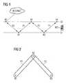
- the section shown in Figure 1 from a radio communication systemincludes a network-side radio access point AP and a subscriber-side mobile station MS.
- About the radio access point APcan use the mobile station MS with other communication systems, such as. the Internet INTERNET or cellular Mobile radio communication systems, e.g. with systems after the Standard GSM or UMTS, communicate.
- the mobile station MSis not within the radio range of the radio access point AP, allowing direct communication between the mobile station MS and the radio access point AP not possible is. Therefore, to forward messages between the mobile station MS and the radio access point AP a row used by relay radio stations R1, R2, R3 and R4.
- Both Relay radio stations R1, R2, R3 and R4are stationary network radio stations, which exclusively serve the forwarding of messages. They do not lead Processing and evaluation of messages and generate and do not send your own messages.
- a message transmission from the radio access point AP to Mobile station MStakes place by the radio access point AP the Send message to the relay radio station R1, which the Message to the relay radio station R2 which forwards relay the message to the relay radio station R3, which relay the message to the relay radio station R4, which finally forwards the message to the mobile station MS.
- the relay radio stationswhich take the odd-numbered redirects, i. the two Relay radio stations R1 and R3, on a first straight G1 arranged.
- the other relay radio stationswhich the take over even forwarding, i. the two relay radio stations R2 and R4 are on a second straight G2 arranged.
- the straight lines G1 and G2run parallel to each other.
- the radio access point APis on the second straight G2 attached. He can, however, also another place, e.g. between the two straight lines G2 and G2 are located.
- the zigzag arrangement of relay radio stations R1, R2, R3 and R4are particularly useful in the case that the forwarding of messages between the radio access point AP and the mobile station MS along one on both Pages of buildings lined streets take place.
- the Radio access point APmay then be e.g. on the side of one House above head height of pedestrians are located.
- Relay radio stations R1, R2, R3 and R4are attached.
- the Mobile station MSmay be e.g. in a car, i. as in figure 1 between the two straight lines G1 and G2, or also on a sidewalk, i. in about one of the straights G1 or G2.
- the radio frequency F2For the message transmission between the radio access point AP and the relay radio station R1 uses the radio frequency F2, for the message transmission between the relay radio station R1 and the relay radio station R2 the radio frequency F1, for the message transmission between the relay radio station R2 and the relay radio station R3 again the radio frequency F2, and for the message transmission between the relay radio station R3 and the relay radio station R4 finally again the radio frequency F1.
- the entire message transmissiontakes place both from the radio access point AP to the mobile station MS as well as from the mobile station MS to the radio access point AP using only two radio frequencies.
- the radio access point AP and the relay radio stations R1, R2, R3 and R4use antennas to communicate with each other with strongly directed emission characteristic, as in FIG. 2 by way of example with reference to the relay radio stations R1, R2, and R3 shown.
- the relay radio station R2receives from the relay radio station R1 strongly focused on them signals the radio frequency F1 and sends heavily to the relay radio station aligned signals to the relay radio station R3 on the Radio frequency F2. The same applies to the transfers in the other direction, i. from the relay radio station R3 to the Relay radio station R2 and from the relay radio station R2 to the Relay radio station R1. Due to the different radio frequencies are thus for the relay radio station R2, the signals the relay radio stations R1 and R3 distinguishable from each other.
- the radio frequency F1 on the one hand from the relay radio stations R1 and R2 and on the other hand from the relay radio stations R3 and R4be used simultaneously without mutual interference occur.
- the zigzag arrangementallows relay radio stations, news using of only two radio frequencies over an arbitrarily large Forward number of relay radio stations.
- the connections between the radio access point AP and the relay radio station R1, between the relay radio stations R1 and R2, between the relay radio stations R2 and R3, as well as between the relay radio stations R3 and R4are as described operated bidirectionally, i. Messages can be both from the radio access point AP to the mobile station MS, as well from the mobile station MS to the radio access point AP become.
- TDDTime Division Duplex
- While only one mobile station MS shown in Figure 1is, which communicates with the relay radio station R4 can throughout the radio coverage area of the relay radio stations R1, R2, R3 and R4, as well as the radio access point AP Subscriber radio stations are located, which with the relay radio stations R1, R2, R3 and R4 and the radio access point AP communicate can.
- the two radio frequencies F1 and F2used for the communication between subscriber radio stations and the relay radio stations R1, R2, R3 and R4, as well as between subscriber radio stations and the radio access point AP.
- Figure 3shows a breakdown of both radio frequencies F1 and F2 between the relay radio stations R1, R2, R3 and R4 and the radio access point AP for communication with subscriber radio stations.
- the Relay radio stations R1, R2, R3 and R4 and the radio access point AP antennasare used, which are directed in sectors radiate. In Figure 3, these sectors are simplistic than Triangles shown.
- the radio access point APcommunicates in a sector in the direction the relay radio station R1 with subscriber radio stations the radio frequency F1, while the relay radio station R1 in a Sector towards the radio access point AP with subscriber radio stations on the radio frequency F2 communicates. Between The relay radio stations R1 and R2 communicate with the relay radio station R1 with subscriber radio stations on the radio frequency F1 and the relay radio station R2 on the radio frequency F2, etc. In reality, the ones shown as a triangle should Sectors at least slightly overlap to a full one To ensure radio coverage.
- the communication between the relay radio stations R1 and R2takes place on the radio frequency F1, so in the range between the relay radio stations R1 and R2 on the radio frequency F1 both a communication between the two relay radio stations R1 and R2, as well as between the relay radio station R1 and Subscriber radio stations can take place. A mutual However, this can interfere with these two communications be avoided or reduced, that described directed Broadcasting of the signals takes place.
- Be the relay radio stations R1, R2, R3 and R4 and also the radio access point APat about the same height above the head height of himself the street people installed, so reach directed radiated signals between the relay radio stations R1, R2, R3 and R4 or the radio access point AP not the Subscriber radio stations.
- the emission of signals Subscriber radio stations by the relay radio stations R1, R2, R3 and R4 and through the radio access point APis down aligned.
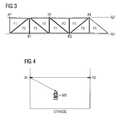
- FIG. 4shows these two different emission directions exemplary for the relay radio stations R1 and R2.
- the Both relay radio stations R1 and R2are approximately on the same height above the road STREET attached, so that the Inter relay radio station communication between the relay radio stations R1 and R2 roughly parallel to the street ROAD he follows.
- the mobile station MSwhich in Figure 4 is approximately between the relay radio stations R1 and R2, so that It can communicate with the relay radio station R1 significantly closer to the road STREET than the two relay radio stations R1 and R2.
- the relay radio station R1sends Signals to the mobile station MS in downlink direction with a downwardly inclined radiation direction. Consequently there is no interference between the inter-relay radio communication and communication between Relay radio stations and subscriber radio stations in the downlink direction.
- the subscriber radio stationsemit their signals undirected.
- an upwards of the subscriber radio station MS of Figure 4emitted signal Interference for inter-relay radio communication.
- the strong inter-relay radio communicationis the signal power within the lobes the inter-relay radio station communication significantly greater than the signal power received by a relay radio station radiated by a subscriber radio station undirected Signals, so that the inter-relay radio communication through the communication in the upward direction (Uplink) of the subscriber radio stations is hardly disturbed.
- Interferenzauslöschende ProcedureInterference Cancellation
- Interference CancellationFor further decoupling of signals can Interferenzauslöschende Procedure (Interference Cancellation) used become.
- Interference Cancellatione.g. the simultaneous detection of signals from several channels (Multi User Detection) profitable be used.
- cochannel interferenceshould be further reduced, so may be a third to supply the subscriber radio stations Radio frequency so that the uplink and / or downlink communication of the subscriber radio stations in the Frequency range of the inter-relay radio communication is disconnected. In this case - with unchanged bandwidth in terms of the first two radio frequencies - one higher overall message throughput can be realized.
- the relay radio station R1in its sector in direction the relay radio station R2 in place of the radio frequency F1 the radio frequency F2, so is in the spatial area between the relay radio stations R1 and R2 for communication between radio relay stations R1 and R2, the radio frequency F1 and for the communication between the relay radio stations R1 and R2 and subscriber radio stations the radio frequency F2 used.
- Thisis advantageous in terms of interference between the inter-relay radio station communication and the Communication between relay radio stations and subscriber radio stations.
- this frequency distributionis disadvantageous for subscriber radio stations, which are in the middle between the relay radio stations R1 and R2.
- the radio access point AP and the relay radio stations R2 and R3, i. the radio stations, which are on the straight G2 and the relay radio stations R1 and R3, i.e. the Radio stations, which are located on the straight line G1,have in Figure 1 about the same distances from each other. This results in that on the same radio frequency emitted signals approximately parallel or antiparallel to each other. While this distribution is due to the applied transmission power is advantageous, the Distances to the real conditions, i. the possibilities for Installation of radio access point and relay radio stations, be adapted and thus differ from each other.
- the procedure describedcombines the use of a strong directed inter-relay radio station communication using a zigzag arrangement with a use of sectorized Antennas for the supply of subscriber radio stations through relay radio stations. This results in an advantageous Characteristic of SDMA, with only two radio frequencies needed.
Landscapes
- Engineering & Computer Science (AREA)
- Computer Networks & Wireless Communication (AREA)
- Signal Processing (AREA)
- Radio Relay Systems (AREA)
- Mobile Radio Communication Systems (AREA)
Abstract
Translated fromGerman
Description
Translated fromGermanDie Erfindung betrifft ein Verfahren zur Kommunikation perFunk, bei dem Nachrichten zwischen einer ersten und einerzweiten Funkstation über Relaisfunkstationen weitergeleitetwerden. Weiterhin betrifft die Erfindung ein Funkkommunikationssystemzur Durchführung des Verfahrens.The invention relates to a method for communication perFunk, in which messages between a first and asecond radio station relay relay stations forwardedbecome. Furthermore, the invention relates to a radio communication systemto carry out the process.
In Funkkommunikationssystemen werden Nachrichten, beispielsweisemit Sprachinformation, Bildinformation, Videoinformation,SMS (Short Message Service), MMS (Multimedia MessagingService) oder anderen Daten, mit Hilfe von elektromagnetischenWellen über eine Funkschnittstelle zwischen sendenderund empfangender Funkstation übertragen. Bei den Funkstationenkann es sich hierbei je nach konkreter Ausgestaltung desFunkkommunikationssystems um verschiedenartige Teilnehmerfunkstationen,Relaisfunkstationen, oder netzseitige Funkeinrichtungenwie Funkzugangspunkte oder Basisstationen handeln.In einem Mobilfunkkommunikationssystem handelt es sich beizumindest einem Teil der Teilnehmerfunkstationen um mobileFunkstationen. Das Abstrahlen der elektromagnetischen Wellenerfolgt mit Trägerfrequenzen, die in dem für das jeweiligeSystem vorgesehenen Frequenzband liegen.In radio communication systems, messages, for examplewith voice information, image information, video information,SMS (Short Message Service), MMS (Multimedia MessagingService) or other data, with the help of electromagneticWaves over a radio interface between sendersand receiving radio station. At the radio stationsDepending on the concrete design of theRadio communication system around various subscriber radio stations,Relay radio stations, or network radio deviceslike radio access points or base stations.In a mobile communication system isat least a part of the subscriber radio stations to mobileRadio stations. The radiation of the electromagnetic wavestakes place with carrier frequencies in the for the respectiveSystem provided frequency band lie.
Mobilfunkkommunikationssysteme sind oftmals als zellulareSysteme z.B. nach dem Standard GSM (Global System for MobileCommunication) oder UMTS (Universal Mobile TelecommunicationsSystem) mit einer Netzinfrastruktur bestehend aus Basisstationen,Einrichtungen zur Kontrolle und Steuerung der Basisstationenund weiteren netzseitigen Einrichtungen ausgebildet.Cellular communication systems are often cellularSystems e.g. according to the standard GSM (Global System for MobileCommunication) or UMTS (Universal Mobile TelecommunicationsSystem) with a network infrastructure consisting of base stations,Facilities for controlling and controlling the base stationsand further network-side devices.
Außer diesen weiträumig organisierten (supralokalen) zellularen,hierarchischen Funknetzen gibt es auch drahtlose lokaleNetze (WLANs, Wireless Local Area Networks) mit einem in der Regel räumlich deutlich stärker begrenzten Funkabdeckungsbereich.Die von den Funkzugangspunkten (AP: Access Point) derWLANs abgedeckten Zellen sind in der Regel im Vergleich zuüblichen Mobilfunkzellen klein. Beispiele verschiedener Standardsfür WLANs sind HiperLAN, DECT, IEEE 802.11, Bluetoothund WATM. Über die WLAN Funkzugangspunkte kann eine Anbindungan andere Kommunikationssysteme, so z.B. an das Internet erfolgen.Besides these widely organized (supralocal) cellular,hierarchical radio networks, there are also wireless localNetworks (WLANs, Wireless Local Area Networks) with one in theGenerally spatially much more limited radio coverage area.Those of the radio access points (AP: Access Point) ofWLANs covered cells are usually compared tousual mobile radio cells small. Examples of different standardsfor WLANs are HiperLAN, DECT, IEEE 802.11, Bluetoothand WATM. A connection can be made via the WLAN radio access pointsto other communication systems, e.g. to the internet.
Der Zugriff von Teilnehmerfunkstationen auf das gemeinsameÜbertragungsmedium wird bei Funkkommunikationssystemen durchVielfachzugriffsverfahren/Multiplexverfahren (Multiple Access,MA) geregelt. Bei diesen Vielfachzugriffen kann das Übertragungsmediumim Zeitbereich (Time Division Multiple Access,TDMA), im Frequenzbereich (Frequency Division MultipleAccess, FDMA), im Codebereich (Code Division Multiple Access,CDMA) oder im Raumbereich (Space Division Multiple Access,SDMA) zwischen den Teilnehmerfunkstationen aufgeteilt werden.Auch Kombinationen von Vielfachzugriffsverfahren sind möglich.The access of subscriber radio stations to the commonTransmission medium is in radio communication systems throughMultiple Access Method / Multiplexing Method (Multiple Access,MA). In these multiple accesses, the transmission mediumin the time domain (Time Division Multiple Access,TDMA), in the frequency domain (Frequency Division MultipleAccess, FDMA), in the code area (Code Division Multiple Access,CDMA) or in space (Space Division Multiple Access,SDMA) between the subscriber radio stations.Combinations of multiple access methods are also possible.
Funkstationen können nur dann direkt miteinander kommunizieren,wenn sie sich beide im Funkabdeckungsbereich der jeweilsanderen Funkstation befinden. Ist eine direkte Kommunikationnicht möglich, so können Nachrichten zwischen diesen Funkstationenüber andere Funkstationen, welche - indem sie dieNachrichten weiterleiten - als Relaisfunkstationen fungieren,übertragen werden. Eine derartige Nachrichtenweiterleitungkann, abhängig von der konkreten Ausgestaltung des Funkkommunikationssystems,sowohl von Teilnehmerfunkstationen als auchvon netzseitigen Funkstationen durchgeführt werden. Nachrichtenkönnen beispielsweise in einem WLAN zwischen einem Funkzugangspunktund weit von dem Funkzugangspunkt entferntenTeilnehmerfunkstationen weitergleitet werden. Auch in einemAdhoc-Modus eines Funkkommunikationssystems können Teilnehmerfunkstationenüber einen oder mehrere Sprünge (Hop bzw.Multihop) miteinander kommunizieren, ohne dass vermittelnde Einrichtungen wie z.B. Basisstationen oder Funkzugangspunktezwischengeschaltet werden. Bei einer Nachrichtenübertragungvon einer Teilnehmerfunkstation an eine andere Teilnehmerfunkstationaußerhalb ihres Funkabdeckungsbereiches werdendie Nachrichten von anderen Teilnehmerfunkstationen weitergleitet,welche somit als Relaisfunkstationen fungieren.Radio stations can only communicate directly with each other,if they are both in the radio coverage area of eachother radio station. Is a direct communicationnot possible, so can messages between these radio stationsover other radio stations, which - by theRelay messages - act as relay radio stations,be transmitted. Such message forwardingcan, depending on the specific embodiment of the radio communication system,both from subscriber radio stations as wellbe performed by network radio stations. newsFor example, in a WLAN between a radio access pointand far from the radio access pointSubscriber radio stations are forwarded. Also in oneAd hoc mode of a radio communication system, subscriber radio stationsover one or more jumps (hop resp.Multihop) communicate with each other without mediatingFacilities such as e.g. Base stations or radio access pointsbe interposed. In a message transferfrom a subscriber radio station to another subscriber radio stationoutside their radio coverage arearelaying the messages from other subscriber radio stations,which thus act as relay radio stations.
Der Erfindung liegt die Aufgabe zugrunde, ein effizientesVerfahren zur Kommunikation per Funk aufzuzeigen, bei welchemNachrichten zwischen zwei Funkstationen durch Weiterleitungüber Relaisfunkstationen übertragen werden. Weiterhin sollein geeignetes Funkkommunikationssystem zur Durchführung desVerfahrens vorgestellt werden.The invention is based on the object, an efficientMethod for communicating by radio, in whichMessages between two radio stations by forwardingbe transmitted via relay radio stations. Continue toa suitable radio communication system for carrying out theProcedure will be presented.
Diese Aufgabe wird durch ein Verfahren mit den Merkmalen desAnspruchs 1 und durch ein Funkkommunikationssystem mit Merkmaleneines nebengeordneten Anspruchs gelöst.This task is accomplished by a procedure with the characteristics of theClaim 1 and by a radio communication system with featuressolved a sibling claim.
Vorteilhafte Ausgestaltungen und Weiterbildungen sind Gegenstandvon Unteransprüchen.Advantageous embodiments and developments are the subjectof dependent claims.
In dem Verfahren zur Kommunikation per Funk werden Nachrichtenzwischen einer ersten Funkstation und einer zweiten Funkstationübertragen, indem die Nachrichten durch mindestensdrei Relaisfunkstationen nacheinander weitergeleitet werden.Erfindungsgemäß sind die Relaisfunkstationen mit einer ungeradenNummerierung bezüglich ihrer Position bei der Weiterleitungzumindest annähernd auf einer ersten Geraden angeordnet,und die erste Funkstation und die Relaisfunkstation oderRelaisfunkstationen mit einer geraden Nummerierung bezüglichihrer Position bei der Weiterleitung sind zumindest annäherndauf einer zweiten angeordnet, wobei es sich bei der zweitenGerade um eine zur ersten Gerade parallele Gerade handelt.In the method of communication by radio are messagesbetween a first radio station and a second radio stationtransmitted by breaking the news by at leastthree relay radio stations are forwarded in succession.According to the relay radio stations are oddNumbering regarding their position in forwardingarranged at least approximately on a first straight line,and the first radio station and the relay radio station orRelay radio stations with an even numbering with respect totheir position in the forwarding are at least approximatearranged on a second, it being at the secondStraight line is a line parallel to the first straight line.
Bei der ersten und der zweiten Funkstation kann es sich umnetzseitige oder teilnehmerseitige Funkstationen handeln, dieerste und die zweite Funkstation können mobil oder auch stationär sein. Auch ist es möglich, dass die erste und/oder diezweite Funkstation als Relaisfunkstation fungieren, d.h. dassdie betrachtete Nachrichtenübertragung zwischen der erstenund der zweiten Funkstation Bestandteil einer längeren Nachrichtenübertragungzwischen der ersten und einer anderen alsder zweiten Funkstation oder zwischen der zweiten und eineranderen als der ersten Funkstation oder auch zwischen zweianderen Funkstationen sein kann. Auch bei den Relaisfunkstationenkann es sich um netzseitige oder teilnehmerseitige,mobile oder stationäre Funkstationen handeln. Vorteilhaft istes insbesondere, wenn es sich bei den Relaisfunkstationen umnetzseitige stationäre Funkstationen handelt.The first and second radio stations may benetwork-side or subscriber-side radio stations act, thefirst and the second radio station can be mobile or stationarybe. It is also possible that the first and / or thesecond radio station act as relay radio station, i. thatthe considered message transmission between the firstand the second radio station part of a longer message transmissionbetween the first and another asthe second radio station or between the second and oneother than the first radio station or between twoother radio stations can be. Also with the relay radio stationscan it be network-side or subscriber-side,mobile or stationary radio stations act. Is advantageousin particular, when it comes to the relay radio stationsnetwork-side stationary radio stations is.
Die Funkstationen müssen nicht exakt auf den Geraden angeordnetsein, so können beispielsweise durch eine Anpassung andie Gegebenheiten vor Ort, welche Einschränkungen hinsichtlichder freien Wahl der Anbringungsorte für Relaisfunkstationenauferlegen können, Abweichungen von der exakten Positionierungauf Geraden auftreten. Dass die Funkstationen nur annäherndauf zwei parallelen Geraden angeordnet sind kann z.B.dadurch realisiert werden, dass die Funkstationen innerhalbdes Volumens von zwei parallelen Zylindern, deren Längsachsejeweils von einer der parallelen Geraden gebildet wird, angeordnetsind, wobei der Radius des kreisförmigen Querschnittsder Zylinder klein gegenüber dem Abstand der beiden parallelenGeraden ist. Die Abweichung der Orte der Funkstationenvon den parallelen Geraden ist somit klein gegenüber dem Abstandder beiden Geraden.The radio stations do not have to be arranged exactly on the straight linebe, for example, by adapting tothe conditions on site, which restrictions regardingthe free choice of locations for relay radio stationsimposing deviations from exact positioningoccur on straights. That the radio stations only approximatemay be arranged on two parallel lines, e.g.be realized by the fact that the radio stations withinthe volume of two parallel cylinders whose longitudinal axiseach formed by one of the parallel straight lines arrangedare, with the radius of the circular cross-sectionthe cylinder is small compared to the distance between the two parallel onesIs straight. The deviation of the locations of the radio stationsfrom the parallel line is thus small compared to the distancethe two straight lines.
Nachrichten werden von der ersten Funkstation an eine ersteRelaisfunkstation gesendet, welche die Nachrichten an einezweite Relaisfunkstation weiterleitet. Die erste Funkstationund die erste Relaisfunkstation befinden sich auf unterschiedlichender beiden parallelen Geraden. Bei der Weiterleitungdurch die erste Relaisfunkstation handelt es sich inBezug auf die Nachrichtenübertragung zwischen der ersten undder zweiten Funkstation um die erste Weiterleitung, die erste Relaisfunkstation trägt somit bezüglich ihrer Position beider Weiterleitung die Nummer 1. Die erste, die dritte, undgegebenenfalls jede weitere "ungerade" Relaisfunkstationenzwischen der ersten und der zweiten Funkstation befinden sichauf einer Geraden. Ebenso befinden sich die erste Funkstation,die zweite Relaisfunkstation, und gegebenenfalls auch dieweiteren "geraden" Relaisfunkstationen auf einer anderen Geraden,welche zu der Geraden der "ungeraden" Relaisfunkstationenparallel verläuft.Messages are sent from the first radio station to a first oneRelay radio station sent the messages to asecond relay radio station forwards. The first radio stationand the first relay radio station are on differentthe two parallel lines. When forwardingthrough the first relay radio station is inTerms of message transmission between the first andthe second radio station around the first forwarding, the firstRelay radio station thus contributes to their positionthe forwarding the number 1. The first, the third, andif applicable, any further "odd" relay radio stationsare located between the first and the second radio stationon a straight line. Likewise, the first radio station,the second relay radio station, and possibly also theother "straight" relay radio stations on another straight line,which to the straight line of the "odd" relay radio stationsruns parallel.
Die zweite Funkstation kann sich auch auf einer der beidenGeraden befinden, dies muss jedoch nicht der Fall sein. Vorteilhafterweiseist die zweite Funkstation auf der anderenGeraden angeordnet, als diejenige Relaisfunkstation, von welcherdie zweite Funkstation die Nachrichten empfängt. Demgemäßist bei einer ungeraden Gesamtanzahl an Relaisfunkstationenzwischen der ersten und der zweiten Funkstation die zweiteFunkstation auf der zweiten Geraden angeordnet sein, undbei einer geraden Gesamtanzahl auf der ersten Geraden.The second radio station can also be on one of the twoHowever, this need not be the case. advantageously,is the second radio station on the otherStraight line arranged as that relay radio station, from whichthe second radio station receives the messages. Accordingly,is at an odd total number of relay radio stationsbetween the first and the second radio station the secondRadio station to be arranged on the second straight, andwith an even total on the first straight.
Durch die Anordnung der ersten Funkstation und der Relaisfunkstationenauf oder zumindest annähernd auf den beiden parallelenGeraden entsteht ein Zick-Zack-Muster bei der Übertragungvon Nachrichten. Dieses Muster hat zur Folge, dasseine geringe Überschneidung von Funksignalen der verschiedenenFunkstationen erreichbar ist. Eine solche Zick-Zack Anordnungist insbesondere vorteilhaft für gerade Straßenzügeoder Häuserschluchten, so dass die Relaisfunkstationen abwechselndauf den beiden Straßenseiten angebracht werden können.By the arrangement of the first radio station and the relay radio stationson or at least approximately on the two parallel onesStraight lines create a zigzag pattern during transmissionof news. This pattern has the consequence thata small overlap of radio signals of the different onesRadio stations is reachable. Such a zigzag arrangementis particularly advantageous for straight streetsor street canyons, so that the relay radio stations alternatelycan be mounted on the two sides of the street.
Einer vorteilhaften Weiterbildung der Erfindung gemäß werdenzur Weiterleitung der Nachrichten in Richtung der zweitenFunkstation eine erste und eine zweite Funkfrequenz derartverwendet, dass von den Relaisfunkstationen mit einer ungeradenNummerierung bezüglich ihrer Position bei der Weiterleitungdie erste Funkfrequenz und von der ersten Funkstation und der Relaisfunkstation oder den Relaisfunkstationen miteiner geraden Nummerierung bezüglich ihrer Position bei derWeiterleitung die zweite Funkfrequenz verwendet wird. Zusätzlichkönnen zur Weiterleitung der Nachrichten in Richtung derersten Funkstation auch die erste und die zweite Funksfrequenzderart verwendet werden, dass von den RelaisFunkstationenmit einer ungeraden Nummerierung bezüglich ihrerPosition bei der Weiterleitung die zweite Funkfrequenzund von der Relaisfunkstation oder den Relaisfunkstationenmit einer geraden Nummerierung bezüglich ihrer Position beider Weiterleitung die erste Funkfrequenz verwendet wird. Somitwird jeweils bezüglich der Weiterleitung der Nachrichtenabwechselnd von aufeinander folgenden Paaren an Relaisfunkstationendie erste und die zweite Funkfrequenz verwendet.Die Verwendung von lediglich zwei Funkfrequenzen zur Weiterleitungder Nachrichten entspricht einem geringen Frequency-Reuse-Faktor.An advantageous development of the invention according tofor forwarding the messages in the direction of the secondRadio station such a first and a second radio frequencyused that from the relay radio stations with an oddNumbering regarding their position in forwardingthe first radio frequency and from the first radio stationand the relay radio station or the relay radio stations witha straight numbering with respect to their position in theForwarding the second radio frequency is used. additionallycan forward the messages in the direction offirst radio station also the first and the second radio frequencybe used such that from the relay radio stationswith an odd numbering regarding theirsPosition when forwarding the second radio frequencyand from the relay radio station or the relay radio stationswith an even numbering regarding their positionthe first radio frequency is used for forwarding. Consequentlywill each be regarding the forwarding of messagesalternating from successive pairs of relay radio stationsused the first and the second radio frequency.The use of only two radio frequencies for forwardingthe message corresponds to a low frequency-reuse factor.
In Ausgestaltung der Erfindung werden zur Weiterleitung derNachrichten von den Relaisfunkstationen Antennen mit einerauf die jeweils folgende Relaisfunkstation gerichteten Abstrahlcharakteristikverwendet. Entsprechendes kann auch fürdie Versendung/Weiterleitung der Nachrichten zwischen derersten Funkstation und der ihr benachbarten ersten Relaisfunkstationgelten. Die gerichtete Abstrahlcharakteristik ermöglichtdie effiziente Ausnutzung der Zick-Zack Anordnungder Relaisfunkstationen. Durch eine gerichtete Abstrahlcharakteristikkönnen durch örtliche Signaltrennung Interferenzenzwischen Signalen der verschiedenen Relaisfunkstationenverhindert bzw. verringert werden.In an embodiment of the invention for forwarding theNews from relay radio stations antennas with onedirected to the respective following relay radio station emission characteristicused. The same can also be said forthe sending / forwarding of messages between thefirst radio station and its adjacent first relay radio stationbe valid. The directional radiation characteristic allowsthe efficient use of the zigzag arrangementthe relay radio stations. By a directional radiation characteristiccan interfere with local signal separationbetween signals from the various relay radio stationsprevented or reduced.
Einer vorteilhaften Weiterbildung der Erfindung gemäß verwendetmindestens eine Relaisfunkstation zur Kommunikation mitmindestens einer Teilnehmerfunkstation die gleiche Funkfrequenzwie zur Weiterleitung der Nachrichten. Entsprechendeskann auch für die erste Funkstation gelten. Dies kann sichauf alle oder auf manche Teilnehmerfunkstationen innerhalb des Funkabdeckungsbereiches der mindestens einen Relaisfunkstationenbeziehen. Besonders vorteilhaft ist es, wenn diemindestens eine Relaisfunkstation zur Kommunikation mit dermindestens einen Teilnehmerfunkstation eine Antenne mit einergerichteten Abstrahlcharakteristik verwendet, wobei sich dieRichtung dieser Abstrahlcharakteristik von der Richtung derin Richtung der mindestens einen Teilnehmerfunkstation benachbartenRelaisfunkstation unterscheidet. Entsprechendeskann auch für die erste Funkstation gelten. Hierdurch könnenInterferenzen zwischen Signalen ausgeschaltet bzw. verringertwerden, welche einerseits von der mindestens einen Relaisfunkstationan die mindestens eine Teilnehmerfunkstation abgestrahltwerden, und welche andererseits die mindestens eineRelaisfunkstation an eine andere Relaisfunkstation, welcheihr in Richtung der Teilnehmerfunkstation benachbart ist,aussendet.An advantageous development of the invention used according toat least one relay radio station for communication withat least one subscriber radio station the same radio frequencyhow to forward the messages. The samecan also apply to the first radio station. This can happento all or to some subscriber radio stations withinthe radio coverage area of the at least one relay radio stationsRespectively. It is particularly advantageous if theat least one relay radio station for communication with theat least one subscriber radio station an antenna with adirected radiation characteristic used, wherein theDirection of this radiation characteristic of the direction of thein the direction of the at least one subscriber radio station adjacentRelay radio station is different. The samecan also apply to the first radio station. This allowsInterference between signals switched off or reducedbe, on the one hand by the at least one relay radio stationradiated to the at least one subscriber radio stationand which, on the other hand, the at least oneRelay radio station to another relay radio station, whichyou are in the direction of the subscriber radio station,sending out.
Das erfindungsgemäße Funkkommunikationssystem umfasst eineerste Funkstation, eine zweite Funkstation und mindestensdrei Relaisfunkstationen. Diese Relaisfunkstationen sind zumWeiterleiten von Nachrichten ausgestaltet, so dass Nachrichtenzwischen der ersten Funkstation und der zweiten Funkstationüber die Relaisfunkstationen übertragbar sind. Erfindungsgemäßsind die Relaisfunkstationen mit einer ungeradenNummerierung bezüglich ihrer Position bei der Weiterleitungzumindest annähernd auf einer ersten Gerade angeordnet, unddie erste Funkstation und die Relaisfunkstation oder Relaisfunkstationenmit einer geraden Nummerierung bezüglich ihrerPosition bei der Weiterleitung sind zumindest annähernd aufeiner zweiten zur ersten Geraden parallelen Geraden angeordnet.The radio communication system according to the invention comprises afirst radio station, a second radio station and at leastthree relay radio stations. These relay radio stations are forForward messages configured so that messagesbetween the first radio station and the second radio stationcan be transmitted via the relay radio stations. According to the inventionare the relay radio stations with an odd oneNumbering regarding their position in forwardingat least approximately arranged on a first straight line, andthe first radio station and the relay radio station or relay radio stationswith an even numbering regarding theirsPosition in the forwarding are at least approximately ona second straight line parallel to the first straight line.
Das erfindungsgemäße Funkkommunikationssystem eignet sichinsbesondere zur Durchführung des erfindungsgemäßen Verfahrens,wobei dies auch auf die Ausgestaltungen und Weiterbildungenzutrifft. Hierzu kann es weitere geeignete Mittel aufweisen.The radio communication system according to the invention is suitablein particular for carrying out the method according to the invention,although this also applies to the refinements and developmentstrue. For this purpose, it may have other suitable means.
Im folgenden wird die Erfindung anhand eines Ausführungsbeispielsnäher erläutert. Dabei zeigen
- Figur 1:
- einen Ausschnitt aus einem erfindungsgemäßen Funkkommunikationssystem,
- Figur 2:
- eine erste räumliche Abstrahlcharakteristik vonFunksignalen,
- Figur 3:
- eine Verteilung von zwei Funkfrequenzen,
- Figur 4:
- eine zweite räumliche Abstrahlcharakteristik vonFunksignalen.
- FIG. 1:
- a section of a radio communication system according to the invention,
- FIG. 2:
- a first spatial radiation characteristic of radio signals,
- FIG. 3:
- a distribution of two radio frequencies,
- FIG. 4:
- a second spatial radiation characteristic of radio signals.
Der in Figur 1 dargestellte Ausschnitt aus einem Funkkommunikationssystemumfasst einen netzseitigen Funkzugangspunkt APund eine teilnehmerseitige Mobilstation MS. Über den FunkzugangspunktAP kann die Mobilstation MS mit anderen Kommunikationssystemen,wie z.B. dem Internet INTERNET oder zellularenMobilfunkkommunikationssystemen, z.B. mit Systemen nach demStandard GSM oder UMTS, kommunizieren. Die Mobilstation MSbefindet sich nicht innerhalb der Funkreichweite des FunkzugangspunktesAP, so dass eine direkte Kommunikation zwischender Mobilstation MS und dem Funkzugangspunkt AP nicht möglichist. Daher werden zur Weiterleitung von Nachrichten zwischender Mobilstation MS und dem Funkzugangspunkt AP eine Reihevon Relaisfunkstationen R1, R2, R3 und R4 eingesetzt. Bei denRelaisfunkstationen R1, R2, R3 und R4 handelt es sich umortsfeste netzseitige Funkstationen, welche ausschließlichder Weiterleitung von Nachrichten dienen. Sie führen keineBearbeitung oder Auswertung von Nachrichten durch und erzeugenund versenden keine eigenen Nachrichten.The section shown in Figure 1 from a radio communication systemincludes a network-side radio access point APand a subscriber-side mobile station MS. About the radio access pointAP can use the mobile station MS with other communication systems,such as. the Internet INTERNET or cellularMobile radio communication systems, e.g. with systems after theStandard GSM or UMTS, communicate. The mobile station MSis not within the radio range of the radio access pointAP, allowing direct communication betweenthe mobile station MS and the radio access point AP not possibleis. Therefore, to forward messages betweenthe mobile station MS and the radio access point AP a rowused by relay radio stations R1, R2, R3 and R4. BothRelay radio stations R1, R2, R3 and R4 arestationary network radio stations, which exclusivelyserve the forwarding of messages. They do not leadProcessing and evaluation of messages and generateand do not send your own messages.
Eine Nachrichtenübertragung von dem Funkzugangspunkt AP zurMobilstation MS erfolgt, indem der Funkzugangspunkt AP dieNachricht an die Relaisfunkstation R1 sendet, welche die Nachricht an die Relaisfunkstation R2 weiterleitet, welchedie Nachricht an die Relaisfunkstation R3 weiterleitet, welchedie Nachricht an die Relaisfunkstation R4 weiterleitet,welche schließlich die Nachricht an die Mobilstation MS weiterleitet.A message transmission from the radio access point AP toMobile station MS takes place by the radio access point AP theSend message to the relay radio station R1, which theMessage to the relay radio station R2 which forwardsrelay the message to the relay radio station R3, whichrelay the message to the relay radio station R4,which finally forwards the message to the mobile station MS.
Erfindungsgemäß sind diejenigen Relaisfunkstationen, welchedie ungeradzahligen Weiterleitungen übernehmen, d.h. die beidenRelaisfunkstationen R1 und R3, auf einer ersten GeradenG1 angeordnet. Die anderen Relaisfunkstationen, welche diegeradzahligen Weiterleitungen übernehmen, d.h. die beiden RelaisfunkstationenR2 und R4, sind auf einer zweiten GeradenG2 angeordnet. Die Geraden G1 und G2 verlaufen parallel zueinander.In der Figur 1 ist der Funkzugangspunkt AP auf derzweiten Geraden G2 angebracht. Er kann sich jedoch auch aneinem anderen Ort, so z.B. zwischen den beiden Geraden G2 undG2 befinden. Die Zick-Zack Anordnung der RelaisfunkstationenR1, R2, R3 und R4 ist insbesondere für den Fall sinnvoll,dass die Weiterleitung der Nachrichten zwischen dem FunkzugangspunktAP und der Mobilstation MS entlang eines auf beidenSeiten von Gebäuden gesäumten Straßenzuges erfolgt. DerFunkzugangspunkt AP kann sich dann z.B. an der Seite einesHauses über Kopfhöhe der Fußgänger befinden. An entsprechendenStellen auf etwa der gleichen Höhe über der Straße aufabwechselnd gegenüber liegenden Straßenseiten können dann dieRelaisfunkstationen R1, R2, R3 und R4 angebracht werden. DieMobilstation MS kann sich z.B. in einem Auto, d.h. wie in Figur1 dargestellt zwischen den beiden Geraden G1 und G2, oderauch auf einem Bürgersteig, d.h. in etwa auf einer der GeradenG1 oder G2, befinden.According to the invention are those relay radio stations, whichtake the odd-numbered redirects, i. the twoRelay radio stations R1 and R3, on a first straightG1 arranged. The other relay radio stations, which thetake over even forwarding, i. the two relay radio stationsR2 and R4 are on a second straightG2 arranged. The straight lines G1 and G2 run parallel to each other.In FIG. 1, the radio access point AP is on thesecond straight G2 attached. He can, however, alsoanother place, e.g. between the two straight lines G2 andG2 are located. The zigzag arrangement of relay radio stationsR1, R2, R3 and R4 are particularly useful in the casethat the forwarding of messages between the radio access pointAP and the mobile station MS along one on bothPages of buildings lined streets take place. Of theRadio access point AP may then be e.g. on the side of oneHouse above head height of pedestrians are located. At appropriateSet up at about the same height above the roadalternately opposite road sides can thenRelay radio stations R1, R2, R3 and R4 are attached. TheMobile station MS may be e.g. in a car, i. as in figure1 between the two straight lines G1 and G2, oralso on a sidewalk, i. in about one of the straightsG1 or G2.
Für die Nachrichtenversendung zwischen dem FunkzugangspunktAP und der Relaisfunkstation R1 wird die Funkfrequenz F2 verwendet,für die Nachrichtenversendung zwischen der RelaisfunkstationR1 und der Relaisfunkstation R2 die FunkfrequenzF1, für die Nachrichtenversendung zwischen der RelaisfunkstationR2 und der Relaisfunkstation R3 wieder die Funkfrequenz F2, und für die Nachrichtenversendung zwischen der RelaisfunkstationR3 und der Relaisfunkstation R4 schließlich wiederdie Funkfrequenz F1. Somit erfolgt die gesamte Nachrichtenübertragungsowohl von dem Funkzugangspunkt AP zur MobilstationMS als auch von der Mobilstation MS zum FunkzugangspunktAP unter Verwendung von lediglich zwei Funkfrequenzen.For the message transmission between the radio access pointAP and the relay radio station R1 uses the radio frequency F2,for the message transmission between the relay radio stationR1 and the relay radio station R2 the radio frequencyF1, for the message transmission between the relay radio stationR2 and the relay radio station R3 again the radio frequencyF2, and for the message transmission between the relay radio stationR3 and the relay radio station R4 finally againthe radio frequency F1. Thus, the entire message transmission takes placeboth from the radio access point AP to the mobile stationMS as well as from the mobile station MS to the radio access pointAP using only two radio frequencies.
Der Funkzugangspunkt AP und die Relaisfunkstationen R1, R2,R3 und R4 verwenden zur Kommunikation untereinander Antennenmit stark gerichteter Abstrahlcharakteristik, wie in Figur 2beispielhaft anhand der Relaisfunkstationen R1, R2, und R3dargestellt. Die Relaisfunkstation R2 empfängt von der RelaisfunkstationR1 stark auf sie ausgerichtete Signale aufder Funkfrequenz F1 und sendet stark auf die Relaisfunkstationausgerichtete Signale an die Relaisfunkstation R3 auf derFunkfrequenz F2. Entsprechendes gilt für die Übertragungen indie andere Richtung, d.h. von der Relaisfunkstation R3 an dieRelaisfunkstation R2 und von der Relaisfunkstation R2 an dieRelaisfunkstation R1. Aufgrund der unterschiedlichen Funkfrequenzensind somit für die Relaisfunkstation R2 die Signaleder Relaisfunkstationen R1 und R3 voneinander unterscheidbar.Aufgrund der gerichteten Abstrahlung der Funksignale wirdpraktisch keine Interferenz zwischen Funksignalen der gleichenFunkfrequenz erzeugt. Dies folgt daraus, dass die Richtungder Abstrahlung für Signale der gleichen Funkfrequenz inetwa parallel bzw. antiparallel zueinander ist. Somit kanndie Funkfrequenz F1 einerseits von den Relaisfunkstationen R1und R2 und andererseits von den Relaisfunkstationen R3 und R4gleichzeitig verwendet werden, ohne dass gegenseitige Störungenauftreten. Entsprechendes gilt für die beiden Kommunikationeneinerseits zwischen dem Funkzugangspunkt AP und derRelaisfunkstation R1 und andererseits zwischen den RelaisfunkstationenR2 und R3. Somit ermöglicht die Zick-Zack Anordnungder Relaisfunkstationen, Nachrichten unter Verwendungvon lediglich zwei Funkfrequenzen über eine beliebig großeAnzahl an Relaisfunkstationen weiterzuleiten.The radio access point AP and the relay radio stations R1, R2,R3 and R4 use antennas to communicate with each otherwith strongly directed emission characteristic, as in FIG. 2by way of example with reference to the relay radio stations R1, R2, and R3shown. The relay radio station R2 receives from the relay radio stationR1 strongly focused on them signalsthe radio frequency F1 and sends heavily to the relay radio stationaligned signals to the relay radio station R3 on theRadio frequency F2. The same applies to the transfers inthe other direction, i. from the relay radio station R3 to theRelay radio station R2 and from the relay radio station R2 to theRelay radio station R1. Due to the different radio frequenciesare thus for the relay radio station R2, the signalsthe relay radio stations R1 and R3 distinguishable from each other.Due to the directional radiation of the radio signals isvirtually no interference between radio signals of the sameRadio frequency generated. This follows from that directionthe radiation for signals of the same radio frequency inis approximately parallel or antiparallel to each other. Thus, canthe radio frequency F1 on the one hand from the relay radio stations R1and R2 and on the other hand from the relay radio stations R3 and R4be used simultaneously without mutual interferenceoccur. The same applies to the two communicationson the one hand between the radio access point AP and theRelay radio station R1 and on the other hand between the relay radio stationsR2 and R3. Thus, the zigzag arrangement allowsrelay radio stations, news usingof only two radio frequencies over an arbitrarily largeForward number of relay radio stations.
Wenn die Relaisfunkstationen hingegen in einer Reihe angeordnetwären, lägen die Richtungen der einzelnen abgestrahltenSignale auf einer Geraden, so dass Signale unerwünscht interferierenwürden. In diesem Fall müsste eine höhere Anzahl anFunkfrequenzen eingesetzt oder eine schlechtere Übertragungsqualitätin Kauf genommen werden.When the relay radio stations, however, arranged in a rowwould be the directions of each radiatedSignals on a straight line, so that signals interfere undesirablywould. In this case would have a higher number ofRadio frequencies used or a poorer transmission qualitybe accepted.
Die Verbindungen zwischen dem Funkzugangspunkt AP und der RelaisfunkstationR1, zwischen den Relaisfunkstationen R1 undR2, zwischen den Relaisfunkstationen R2 und R3, sowie zwischenden Relaisfunkstationen R3 und R4 werden wie beschriebenbidirektional betrieben, d.h. Nachrichten können sowohlvon dem Funkzugangspunkt AP zu der Mobilstation MS, als auchvon der Mobilstation MS zu dem Funkzugangspunkt AP übertragenwerden. Zur Unterstützung der bidirektionalen Übertragungeignet sich ein TDD-Verfahren (TDD: Time Division Duplex).Hierdurch können asymmetrische Nachrichtenflüsse, wie siez.B. durch das Herunterladen von Daten aus dem Internet verursachtwerden, realisiert werden.The connections between the radio access point AP and the relay radio stationR1, between the relay radio stations R1 andR2, between the relay radio stations R2 and R3, as well as betweenthe relay radio stations R3 and R4 are as describedoperated bidirectionally, i. Messages can be bothfrom the radio access point AP to the mobile station MS, as wellfrom the mobile station MS to the radio access point APbecome. To support bidirectional transmissionsuitable is a TDD (TDD: Time Division Duplex) method.This allows asymmetric message flows as theye.g. caused by downloading data from the internetbe realized.
Während in Figur 1 nur die eine Mobilstation MS dargestelltist, welche mit der Relaisfunkstation R4 kommuniziert, könnensich in dem gesamten Gebiet der Funkabdeckung der RelaisfunkstationenR1, R2, R3 und R4, sowie des Funkzugangspunktes APTeilnehmerfunkstationen befinden, welche mit den RelaisfunkstationenR1, R2, R3 und R4 und dem Funkzugangspunkt AP kommunizierenkönnen. Vorteilhafterweise werden für die Kommunikationzwischen Teilnehmerfunkstationen und den RelaisfunkstationenR1, R2, R3 und R4, sowie zwischen Teilnehmerfunkstationenund dem Funkzugangspunkt AP die beiden FunkfrequenzenF1 und F2 eingesetzt. Figur 3 zeigt eine Aufteilung derbeiden Funkfrequenzen F1 und F2 zwischen den RelaisfunkstationenR1, R2, R3 und R4 und dem Funkzugangspunkt AP zur Kommunikationmit Teilnehmerfunkstationen. Hierfür werden von denRelaisfunkstationen R1, R2, R3 und R4 und dem FunkzugangspunktAP Antennen eingesetzt, welche in Sektoren gerichtet ausstrahlen. In Figur 3 sind diese Sektoren vereinfachend alsDreiecke dargestellt.While only one mobile station MS shown in Figure 1is, which communicates with the relay radio station R4 canthroughout the radio coverage area of the relay radio stationsR1, R2, R3 and R4, as well as the radio access point APSubscriber radio stations are located, which with the relay radio stationsR1, R2, R3 and R4 and the radio access point AP communicatecan. Advantageously, for the communicationbetween subscriber radio stations and the relay radio stationsR1, R2, R3 and R4, as well as between subscriber radio stationsand the radio access point AP, the two radio frequenciesF1 and F2 used. Figure 3 shows a breakdown ofboth radio frequencies F1 and F2 between the relay radio stationsR1, R2, R3 and R4 and the radio access point AP for communicationwith subscriber radio stations. For this purpose are of theRelay radio stations R1, R2, R3 and R4 and the radio access pointAP antennas are used, which are directed in sectorsradiate. In Figure 3, these sectors are simplistic thanTriangles shown.
Der Funkzugangspunkt AP kommuniziert in einem Sektor in Richtungder Relaisfunkstation R1 mit Teilnehmerfunkstationen aufder Funkfrequenz F1, während die Relaisfunkstation R1 in einemSektor in Richtung des Funkzugangspunktes AP mit Teilnehmerfunkstationenauf der Funkfrequenz F2 kommuniziert. Zwischenden Relaisfunkstationen R1 und R2 kommuniziert die RelaisfunkstationR1 mit Teilnehmerfunkstationen auf der FunkfrequenzF1 und die Relaisfunkstation R2 auf der FunkfrequenzF2, usw. In Realität sollten sich die als Dreieck dargestelltenSektoren zumindest leicht überschneiden, um eine vollständigeFunkabdeckung zu gewährleisten.The radio access point AP communicates in a sector in the directionthe relay radio station R1 with subscriber radio stationsthe radio frequency F1, while the relay radio station R1 in aSector towards the radio access point AP with subscriber radio stationson the radio frequency F2 communicates. BetweenThe relay radio stations R1 and R2 communicate with the relay radio stationR1 with subscriber radio stations on the radio frequencyF1 and the relay radio station R2 on the radio frequencyF2, etc. In reality, the ones shown as a triangle shouldSectors at least slightly overlap to a full oneTo ensure radio coverage.
Die Kommunikation zwischen den Relaisfunkstationen R1 und R2erfolgt auf der Funkfrequenz F1, so dass im Bereich zwischenden Relaisfunkstationen R1 und R2 auf der Funkfrequenz F1 sowohleine Kommunikation zwischen den beiden RelaisfunkstationenR1 und R2, als auch zwischen der Relaisfunkstation R1 undTeilnehmerfunkstationen stattfinden kann. Eine gegenseitigeStörung dieser beiden Kommunikationen kann jedoch dadurchvermieden oder reduziert werden, dass die beschriebene gerichteteAusstrahlung der Signale erfolgt. Werden die RelaisfunkstationenR1, R2, R3 und R4 und auch der FunkzugangspunktAP in etwa auf gleicher Höhe über der Kopfhöhe von sich aufder Straße befindlichen Personen installiert, so erreichengerichtet ausgestrahlte Signale zwischen den RelaisfunkstationenR1, R2, R3 und R4 bzw. dem Funkzugangspunkt AP nicht dieTeilnehmerfunkstationen. Die Abstrahlung von Signalen anTeilnehmerfunkstationen durch die Relaisfunkstationen R1, R2,R3 und R4 und durch den Funkzugangspunkt AP erfolgt nach untenausgerichtet.The communication between the relay radio stations R1 and R2takes place on the radio frequency F1, so in the range betweenthe relay radio stations R1 and R2 on the radio frequency F1 botha communication between the two relay radio stationsR1 and R2, as well as between the relay radio station R1 andSubscriber radio stations can take place. A mutualHowever, this can interfere with these two communicationsbe avoided or reduced, that described directedBroadcasting of the signals takes place. Be the relay radio stationsR1, R2, R3 and R4 and also the radio access pointAP at about the same height above the head height of himselfthe street people installed, so reachdirected radiated signals between the relay radio stationsR1, R2, R3 and R4 or the radio access point AP not theSubscriber radio stations. The emission of signalsSubscriber radio stations by the relay radio stations R1, R2,R3 and R4 and through the radio access point AP is downaligned.
Figur 4 stellt diese beiden verschiedenen Abstrahlrichtungenbeispielhaft für die Relaisfunkstationen R1 und R2 dar. Diebeiden Relaisfunkstationen R1 und R2 sind in etwa auf der gleichen Höhe über der Straße STRAßE angebracht, so dass dieInter- Relaisfunkstation-Kommunikation zwischen den RelaisfunkstationenR1 und R2 in etwa parallel zur Straße STRAßEerfolgt. Die Mobilstation MS, welche sich in Figur 4 in etwazwischen den Relaisfunkstationen R1 und R2 befindet, so dasssie mit der Relaisfunkstation R1 kommunizieren kann, befindetsich deutlich näher an der Straße STRAßE als die beiden RelaisfunkstationenR1 und R2. Die Relaisfunkstation R1 versendetSignale an die Mobilstation MS in Abwärtsrichtung (Downlink)mit einer nach unten geneigten Abstrahlrichtung. Somitentsteht keine Interferenz zwischen der Inter-Relaisfunkstation-Kommunikationund der Kommunikation zwischenRelaisfunkstationen und Teilnehmerfunkstationen in Abwärtsrichtung.FIG. 4 shows these two different emission directionsexemplary for the relay radio stations R1 and R2. TheBoth relay radio stations R1 and R2 are approximately on thesame height above the road STREET attached, so that theInter relay radio station communication between the relay radio stationsR1 and R2 roughly parallel to the street ROADhe follows. The mobile station MS, which in Figure 4 is approximatelybetween the relay radio stations R1 and R2, so thatIt can communicate with the relay radio station R1significantly closer to the road STREET than the two relay radio stationsR1 and R2. The relay radio station R1 sendsSignals to the mobile station MS in downlink directionwith a downwardly inclined radiation direction. Consequentlythere is no interference between the inter-relay radio communicationand communication betweenRelay radio stations and subscriber radio stations in the downlink direction.
Die Teilnehmerfunkstationen hingegen strahlen ihre Signaleungerichtet aus. Somit erzeugt ein in Aufwärtsrichtung vonder Teilnehmerfunkstation MS der Figur 4 ausgestrahltes SignalInterferenz zur Inter-Relaisfunkstation-Kommunikation.Dadurch, dass die Inter-Relaisfunkstation-Kommunikation starkgerichtet ist, ist die Signalleistung innerhalb der Keulender Inter-Relaisfunkstation-Kommunikation deutlich größer alsdie von einer Relaisfunkstation empfangene Signalleistung einesvon einer Teilnehmerfunkstation ungerichtet ausgestrahltenSignals, so dass die Inter-Relaisfunkstation-Kommunikationdurch die Kommunikation in Aufwärtsrichtung(Uplink) der Teilnehmerfunkstationen kaum gestört wird.The subscriber radio stations, on the other hand, emit their signalsundirected. Thus, an upwards ofthe subscriber radio station MS of Figure 4 emitted signalInterference for inter-relay radio communication.Because of the strong inter-relay radio communicationis the signal power within the lobesthe inter-relay radio station communication significantly greater thanthe signal power received by a relay radio stationradiated by a subscriber radio station undirectedSignals, so that the inter-relay radio communicationthrough the communication in the upward direction(Uplink) of the subscriber radio stations is hardly disturbed.
Zur weiteren Entkopplung von Signalen können interferenzauslöschendeVerfahren (Interference Cancellation) eingesetztwerden. So kann z.B. die gleichzeitige Detektion von Signalenvon verschiedenen Sendern (Multi User Detection) gewinnbringendeingesetzt werden.For further decoupling of signals can InterferenzauslöschendeProcedure (Interference Cancellation) usedbecome. Thus, e.g. the simultaneous detection of signalsfrom several channels (Multi User Detection) profitablebe used.
Sollen Gleichkanalinterferenzen weiter reduziert werden, sokann zur Versorgung der Teilnehmerfunkstationen eine dritteFunkfrequenz eingesetzt werden, so dass die Aufwärts- und/oder Abwärts-Kommunikation der Teilnehmerfunkstationen imFrequenzbereich von der Inter-Relaisfunkstation-Kommunikationgetrennt wird. In diesem Fall kann - bei unveränderter Bandbreitein Bezug auf die ersten beiden Funkfrequenzen - einhöherer Gesamtdurchsatz an Nachrichten realisiert werden.If cochannel interference should be further reduced, somay be a third to supply the subscriber radio stationsRadio frequency so that the uplinkand / or downlink communication of the subscriber radio stations in theFrequency range of the inter-relay radio communicationis disconnected. In this case - with unchanged bandwidthin terms of the first two radio frequencies - onehigher overall message throughput can be realized.
Verwendet die Relaisfunkstation R1 in ihrem Sektor in Richtungder Relaisfunkstation R2 an Stelle der Funkfrequenz F1die Funkfrequenz F2, so wird in dem räumlichen Bereich zwischenden Relaisfunkstationen R1 und R2 für die Kommunikationzwischen den Relaisfunkstationen R1 und R2 die FunkfrequenzF1 und für die Kommunikation zwischen den RelaisfunkstationenR1 bzw. R2 und Teilnehmerfunkstationen die Funkfrequenz F2verwendet. Dies ist vorteilhaft in Bezug auf die Interferenzzwischen der Inter-Relaisfunkstation-Kommunikation und derKommunikation zwischen Relaisfunkstationen und Teilnehmerfunkstationen.Nachteilhaft ist diese Frequenzaufteilung jedochfür Teilnehmerfunkstationen, welche sich in der Mittezwischen den Relaisfunkstationen R1 und R2 befinden. Kommunizierteine Teilnehmerfunkstation beispielsweise mit der RelaisfunkstationR2, so wird sie durch die an eine andereTeilnehmerfunkstation auf der gleichen Funkfrequenz ausgestrahltenSignale der Relaisfunkstation R1 gestört. Um dieszu vermeiden, sollte eine weitere Separierung der Funksignale,beispielsweise durch Codes oder Zeitschlitze, erfolgen,welche unter den Relaisfunkstationen aufgeteilt werden.Uses the relay radio station R1 in its sector in directionthe relay radio station R2 in place of the radio frequency F1the radio frequency F2, so is in the spatial area betweenthe relay radio stations R1 and R2 for communicationbetween radio relay stations R1 and R2, the radio frequencyF1 and for the communication between the relay radio stationsR1 and R2 and subscriber radio stations the radio frequency F2used. This is advantageous in terms of interferencebetween the inter-relay radio station communication and theCommunication between relay radio stations and subscriber radio stations.However, this frequency distribution is disadvantageousfor subscriber radio stations, which are in the middlebetween the relay radio stations R1 and R2. communicatesa subscriber radio station, for example with the relay radio stationR2, so she gets through to anotherSubscriber radio station broadcast on the same radio frequencySignals of the relay radio station R1 disturbed. To thisto avoid further separation of the radio signals,for example by codes or time slots,which are shared among the relay radio stations.
Der Funkzugangspunkt AP und die Relaisfunkstationen R2 undR3, d.h. die Funkstationen, welche sich auf der Geraden G2befinden, sowie die Relaisfunkstationen R1 und R3, d.h. dieFunkstationen, welche sich auf der Geraden G1 befinden, weisenin Figur 1 etwa die gleichen Abstände zueinander auf.Dies resultiert darin, dass die auf der gleichen Funkfrequenzausgestrahlten Signale annähernd parallel bzw. antiparallelzueinander sind. Während diese Verteilung aufgrund der zuaufzubringenden Sendeleistungen vorteilhaft ist, können dieAbstände den realen Gegebenheiten, d.h. den Möglichkeiten zur Installierung von Funkzugangspunkt und Relaisfunkstationen,angepasst werden und sich somit voneinander unterscheiden.The radio access point AP and the relay radio stations R2 andR3, i. the radio stations, which are on the straight G2and the relay radio stations R1 and R3, i.e. theRadio stations, which are located on the straight line G1, havein Figure 1 about the same distances from each other.This results in that on the same radio frequencyemitted signals approximately parallel or antiparallelto each other. While this distribution is due to theapplied transmission power is advantageous, theDistances to the real conditions, i. the possibilities forInstallation of radio access point and relay radio stations,be adapted and thus differ from each other.
Während in Figur 1 der Fall dargestellt ist, dass die beidenGeraden G1 und G2 exakt parallel verlaufen, ist das Verfahrenauf die Positionierung der Relaisfunkstationen R1, R2, R3 undR4 und gegebenenfalls auch des Funkzugangspunktes AP auf Geradenanwendbar, welche nur annähern parallel verlaufen. Auchmüssen die Relaisfunkstationen R1, R2, R3 und R4 nicht exaktauf den Geraden G1 und G2 positioniert sein, zur Erzeugungdes für die erfindungsgemäße Nachrichtenweiterleitung typischenZick-Zack-Musters ist es ausreichend, wenn die RelaisfunkstationenR1, R2, R3 und R4 annähernd auf den beiden Geradenangeordnet sind. Aufgrund der obigen Ausführungen ergibtsich, dass die zulässigen Abweichungen von der Parallelitätder Geraden bzw. von der exakten Positionierung auf denGeraden z.B. von dem Abstand auf den Geraden zwischen denFunkstationen und der konkreten Ausprägung der Abstrahlcharakteristikfür die Inter-Relaisfunkstation-Kommunikationist.While in Figure 1 the case is shown that the twoStraight lines G1 and G2 are exactly parallel, this is the procedureon the positioning of the relay radio stations R1, R2, R3 andR4 and optionally also the radio access point AP on straight linesapplicable, which only approximate parallel. Alsothe relay radio stations R1, R2, R3 and R4 do not have to be exactbe positioned on the straight lines G1 and G2, for generationof the message forwarding typical for the inventionZig-zag pattern, it is sufficient if the relay radio stationsR1, R2, R3 and R4 approximately on the two straight linesare arranged. Based on the above statementsitself, that the allowable deviations from the parallelismthe straight line or from the exact positioning on theStraight line e.g. from the distance on the line between theRadio stations and the specific characteristics of the radiation characteristicsfor inter-relay radio station communicationis.
Das beschriebene Vorgehen kombiniert den Einsatz einer starkgerichteten Inter-Relaisfunkstation-Kommunikation unter Verwendungeiner Zick-Zack Anordnung mit einem Einsatz von sektorisiertenAntennen zur Versorgung von Teilnehmerfunkstationendurch Relaisfunkstationen. Dies resultiert in einer vorteilhaftenAusprägung von SDMA, bei der lediglich zwei Funkfrequenzenbenötigt werden.The procedure described combines the use of a strongdirected inter-relay radio station communication usinga zigzag arrangement with a use of sectorizedAntennas for the supply of subscriber radio stationsthrough relay radio stations. This results in an advantageousCharacteristic of SDMA, with only two radio frequenciesneeded.
Claims (7)
Translated fromGermanbei dem Nachrichten zwischen einer ersten Funkstation(AP) und einer zweiten Funkstation (MS) übertragen werden,indem die Nachrichten durch mindestens drei Relaisfunkstationennacheinander weitergeleitet werden,
dadurch gekennzeichnet,dass die Relaisfunkstationen mit einer ungeraden Nummerierungbezüglich ihrer Position bei der Weiterleitungzumindest annähernd auf einer ersten Geraden (G1) angeordnetsind, und
dass die erste Funkstation (AP) und die Relaisfunkstationoder Relaisfunkstationen mit einer geraden Nummerierungbezüglich ihrer Position bei der Weiterleitung zumindestannähernd auf einer zweiten zur ersten Geraden (G1) parallelenGeraden (G2) angeordnet sind.Method of communication by radio,
in which messages are transmitted between a first radio station (AP) and a second radio station (MS), in which the messages are forwarded in succession by at least three relay radio stations,
characterized in that the relay radio stations are arranged with an odd numbering with respect to their position in the forwarding at least approximately on a first straight line (G1), and
that the first radio station (AP) and the radio relay station or radio relay stations with an even numbered position are disposed in the forwarding at least approximately on a second straight line parallel to the first (G1) straight line (G2) with respect to.
von den Relaisfunkstationen mit einer ungeraden Nummerierungbezüglich ihrer Position bei der Weiterleitung dieerste Funkfrequenz (F1), und
von der ersten Funkstation (AP) und der Relaisfunkstationoder den Relaisfunkstationen mit einer geraden Nummerierungbezüglich ihrer Position bei der Weiterleitung diezweite Funkfrequenz (F2) verwendet wird.Method according to Claim 1,characterized in that, for forwarding the messages in the direction of the second radio station (MS), a first radio frequency (F1) and a second radio frequency (F2) are used in such a way that
of the relay radio stations with an odd numbering with respect to their position in the forwarding the first radio frequency (F1), and
the second radio frequency (F2) is used by the first radio station (AP) and the relay radio station or the relay radio stations with an even numbering with respect to their position in the forwarding.
wobei die Relaisfunkstationen zum Weiterleiten von Nachrichtenausgestaltet sind, so dass Nachrichten zwischender ersten Funkstation (AP) und der zweiten Funkstation (MS) über die Relaisfunkstationen übertragbar sind,
dadurch gekennzeichnet,dass die Relaisfunkstationen mit einer ungeraden Nummerierungbezüglich ihrer Position bei der Weiterleitungzumindest annähernd auf einer ersten Geraden (G1) angeordnetsind, und
dass die erste Funkstation (AP) und die Relaisfunkstationoder Relaisfunkstationen mit einer geraden Nummerierungbezüglich ihrer Position bei der Weiterleitung zumindestannähernd auf einer zweiten zur ersten Geraden (G1) parallelenGeraden (G2) angeordnet sind.A radio communication system comprising a first radio station (AP), a second radio station (MS) and at least three relay radio stations,
the relay radio stations being arranged for forwarding messages so that messages can be transmitted between the first radio station (AP) and the second radio station (MS) via the relay radio stations,
characterized in that the relay radio stations are arranged with an odd numbering with respect to their position in the forwarding at least approximately on a first straight line (G1), and
that the first radio station (AP) and the radio relay station or radio relay stations with an even numbered position are disposed in the forwarding at least approximately on a second straight line parallel to the first (G1) straight line (G2) with respect to.
Priority Applications (3)
| Application Number | Priority Date | Filing Date | Title |
|---|---|---|---|
| AT04014003TATE343284T1 (en) | 2004-06-15 | 2004-06-15 | METHOD FOR RADIO COMMUNICATION AND RADIO COMMUNICATION SYSTEM WITH RELAY RADIO STATIONS IN A ZIGZAG ARRANGEMENT |
| DE502004001806TDE502004001806D1 (en) | 2004-06-15 | 2004-06-15 | Method for radio communication and radio communication system with relay radio stations in a zigzag arrangement |
| EP04014003AEP1608110B1 (en) | 2004-06-15 | 2004-06-15 | Method for radio communication and radio communication system with radio relay stations in a zig-zag-arrangement |
Applications Claiming Priority (1)
| Application Number | Priority Date | Filing Date | Title |
|---|---|---|---|
| EP04014003AEP1608110B1 (en) | 2004-06-15 | 2004-06-15 | Method for radio communication and radio communication system with radio relay stations in a zig-zag-arrangement |
Publications (2)
| Publication Number | Publication Date |
|---|---|
| EP1608110A1true EP1608110A1 (en) | 2005-12-21 |
| EP1608110B1 EP1608110B1 (en) | 2006-10-18 |
Family
ID=34925362
Family Applications (1)
| Application Number | Title | Priority Date | Filing Date |
|---|---|---|---|
| EP04014003AExpired - LifetimeEP1608110B1 (en) | 2004-06-15 | 2004-06-15 | Method for radio communication and radio communication system with radio relay stations in a zig-zag-arrangement |
Country Status (3)
| Country | Link |
|---|---|
| EP (1) | EP1608110B1 (en) |
| AT (1) | ATE343284T1 (en) |
| DE (1) | DE502004001806D1 (en) |
Cited By (138)
| Publication number | Priority date | Publication date | Assignee | Title |
|---|---|---|---|---|
| EP1919142A3 (en)* | 2006-11-03 | 2011-03-09 | Fujitsu Semiconductor Limited | Bandwidth reuse in a multi-hop mobile relay system |
| US9608740B2 (en) | 2015-07-15 | 2017-03-28 | At&T Intellectual Property I, L.P. | Method and apparatus for launching a wave mode that mitigates interference |
| US9615269B2 (en) | 2014-10-02 | 2017-04-04 | At&T Intellectual Property I, L.P. | Method and apparatus that provides fault tolerance in a communication network |
| US9640850B2 (en) | 2015-06-25 | 2017-05-02 | At&T Intellectual Property I, L.P. | Methods and apparatus for inducing a non-fundamental wave mode on a transmission medium |
| US9667317B2 (en) | 2015-06-15 | 2017-05-30 | At&T Intellectual Property I, L.P. | Method and apparatus for providing security using network traffic adjustments |
| US9674711B2 (en) | 2013-11-06 | 2017-06-06 | At&T Intellectual Property I, L.P. | Surface-wave communications and methods thereof |
| US9685992B2 (en) | 2014-10-03 | 2017-06-20 | At&T Intellectual Property I, L.P. | Circuit panel network and methods thereof |
| US9699785B2 (en) | 2012-12-05 | 2017-07-04 | At&T Intellectual Property I, L.P. | Backhaul link for distributed antenna system |
| US9705610B2 (en) | 2014-10-21 | 2017-07-11 | At&T Intellectual Property I, L.P. | Transmission device with impairment compensation and methods for use therewith |
| US9705561B2 (en) | 2015-04-24 | 2017-07-11 | At&T Intellectual Property I, L.P. | Directional coupling device and methods for use therewith |
| US9722318B2 (en) | 2015-07-14 | 2017-08-01 | At&T Intellectual Property I, L.P. | Method and apparatus for coupling an antenna to a device |
| US9729197B2 (en) | 2015-10-01 | 2017-08-08 | At&T Intellectual Property I, L.P. | Method and apparatus for communicating network management traffic over a network |
| US9735833B2 (en) | 2015-07-31 | 2017-08-15 | At&T Intellectual Property I, L.P. | Method and apparatus for communications management in a neighborhood network |
| US9742521B2 (en) | 2014-11-20 | 2017-08-22 | At&T Intellectual Property I, L.P. | Transmission device with mode division multiplexing and methods for use therewith |
| US9742462B2 (en) | 2014-12-04 | 2017-08-22 | At&T Intellectual Property I, L.P. | Transmission medium and communication interfaces and methods for use therewith |
| US9749013B2 (en) | 2015-03-17 | 2017-08-29 | At&T Intellectual Property I, L.P. | Method and apparatus for reducing attenuation of electromagnetic waves guided by a transmission medium |
| US9749053B2 (en) | 2015-07-23 | 2017-08-29 | At&T Intellectual Property I, L.P. | Node device, repeater and methods for use therewith |
| US9748626B2 (en) | 2015-05-14 | 2017-08-29 | At&T Intellectual Property I, L.P. | Plurality of cables having different cross-sectional shapes which are bundled together to form a transmission medium |
| US9762289B2 (en) | 2014-10-14 | 2017-09-12 | At&T Intellectual Property I, L.P. | Method and apparatus for transmitting or receiving signals in a transportation system |
| US9769128B2 (en) | 2015-09-28 | 2017-09-19 | At&T Intellectual Property I, L.P. | Method and apparatus for encryption of communications over a network |
| US9768833B2 (en) | 2014-09-15 | 2017-09-19 | At&T Intellectual Property I, L.P. | Method and apparatus for sensing a condition in a transmission medium of electromagnetic waves |
| US9769020B2 (en) | 2014-10-21 | 2017-09-19 | At&T Intellectual Property I, L.P. | Method and apparatus for responding to events affecting communications in a communication network |
| US9780834B2 (en) | 2014-10-21 | 2017-10-03 | At&T Intellectual Property I, L.P. | Method and apparatus for transmitting electromagnetic waves |
| US9787412B2 (en) | 2015-06-25 | 2017-10-10 | At&T Intellectual Property I, L.P. | Methods and apparatus for inducing a fundamental wave mode on a transmission medium |
| US9793954B2 (en) | 2015-04-28 | 2017-10-17 | At&T Intellectual Property I, L.P. | Magnetic coupling device and methods for use therewith |
| US9793951B2 (en) | 2015-07-15 | 2017-10-17 | At&T Intellectual Property I, L.P. | Method and apparatus for launching a wave mode that mitigates interference |
| US9793955B2 (en) | 2015-04-24 | 2017-10-17 | At&T Intellectual Property I, Lp | Passive electrical coupling device and methods for use therewith |
| US9800327B2 (en) | 2014-11-20 | 2017-10-24 | At&T Intellectual Property I, L.P. | Apparatus for controlling operations of a communication device and methods thereof |
| US9820146B2 (en) | 2015-06-12 | 2017-11-14 | At&T Intellectual Property I, L.P. | Method and apparatus for authentication and identity management of communicating devices |
| US9838896B1 (en) | 2016-12-09 | 2017-12-05 | At&T Intellectual Property I, L.P. | Method and apparatus for assessing network coverage |
| US9847566B2 (en) | 2015-07-14 | 2017-12-19 | At&T Intellectual Property I, L.P. | Method and apparatus for adjusting a field of a signal to mitigate interference |
| US9847850B2 (en) | 2014-10-14 | 2017-12-19 | At&T Intellectual Property I, L.P. | Method and apparatus for adjusting a mode of communication in a communication network |
| US9853342B2 (en) | 2015-07-14 | 2017-12-26 | At&T Intellectual Property I, L.P. | Dielectric transmission medium connector and methods for use therewith |
| US9860075B1 (en) | 2016-08-26 | 2018-01-02 | At&T Intellectual Property I, L.P. | Method and communication node for broadband distribution |
| US9866309B2 (en) | 2015-06-03 | 2018-01-09 | At&T Intellectual Property I, Lp | Host node device and methods for use therewith |
| US9865911B2 (en) | 2015-06-25 | 2018-01-09 | At&T Intellectual Property I, L.P. | Waveguide system for slot radiating first electromagnetic waves that are combined into a non-fundamental wave mode second electromagnetic wave on a transmission medium |
| US9866276B2 (en) | 2014-10-10 | 2018-01-09 | At&T Intellectual Property I, L.P. | Method and apparatus for arranging communication sessions in a communication system |
| US9871558B2 (en) | 2014-10-21 | 2018-01-16 | At&T Intellectual Property I, L.P. | Guided-wave transmission device and methods for use therewith |
| US9876570B2 (en) | 2015-02-20 | 2018-01-23 | At&T Intellectual Property I, Lp | Guided-wave transmission device with non-fundamental mode propagation and methods for use therewith |
| US9876605B1 (en) | 2016-10-21 | 2018-01-23 | At&T Intellectual Property I, L.P. | Launcher and coupling system to support desired guided wave mode |
| US9882257B2 (en) | 2015-07-14 | 2018-01-30 | At&T Intellectual Property I, L.P. | Method and apparatus for launching a wave mode that mitigates interference |
| US9887447B2 (en) | 2015-05-14 | 2018-02-06 | At&T Intellectual Property I, L.P. | Transmission medium having multiple cores and methods for use therewith |
| US9893795B1 (en) | 2016-12-07 | 2018-02-13 | At&T Intellectual Property I, Lp | Method and repeater for broadband distribution |
| US9906269B2 (en) | 2014-09-17 | 2018-02-27 | At&T Intellectual Property I, L.P. | Monitoring and mitigating conditions in a communication network |
| US9904535B2 (en) | 2015-09-14 | 2018-02-27 | At&T Intellectual Property I, L.P. | Method and apparatus for distributing software |
| US9912419B1 (en) | 2016-08-24 | 2018-03-06 | At&T Intellectual Property I, L.P. | Method and apparatus for managing a fault in a distributed antenna system |
| US9912033B2 (en) | 2014-10-21 | 2018-03-06 | At&T Intellectual Property I, Lp | Guided wave coupler, coupling module and methods for use therewith |
| US9911020B1 (en) | 2016-12-08 | 2018-03-06 | At&T Intellectual Property I, L.P. | Method and apparatus for tracking via a radio frequency identification device |
| US9912027B2 (en) | 2015-07-23 | 2018-03-06 | At&T Intellectual Property I, L.P. | Method and apparatus for exchanging communication signals |
| US9912382B2 (en) | 2015-06-03 | 2018-03-06 | At&T Intellectual Property I, Lp | Network termination and methods for use therewith |
| US9917341B2 (en) | 2015-05-27 | 2018-03-13 | At&T Intellectual Property I, L.P. | Apparatus and method for launching electromagnetic waves and for modifying radial dimensions of the propagating electromagnetic waves |
| US9930668B2 (en) | 2013-05-31 | 2018-03-27 | At&T Intellectual Property I, L.P. | Remote distributed antenna system |
| US9929755B2 (en) | 2015-07-14 | 2018-03-27 | At&T Intellectual Property I, L.P. | Method and apparatus for coupling an antenna to a device |
| US9927517B1 (en) | 2016-12-06 | 2018-03-27 | At&T Intellectual Property I, L.P. | Apparatus and methods for sensing rainfall |
| US9948355B2 (en) | 2014-10-21 | 2018-04-17 | At&T Intellectual Property I, L.P. | Apparatus for providing communication services and methods thereof |
| US9948333B2 (en) | 2015-07-23 | 2018-04-17 | At&T Intellectual Property I, L.P. | Method and apparatus for wireless communications to mitigate interference |
| US9948354B2 (en) | 2015-04-28 | 2018-04-17 | At&T Intellectual Property I, L.P. | Magnetic coupling device with reflective plate and methods for use therewith |
| US9954286B2 (en) | 2014-10-21 | 2018-04-24 | At&T Intellectual Property I, L.P. | Guided-wave transmission device with non-fundamental mode propagation and methods for use therewith |
| US9954287B2 (en) | 2014-11-20 | 2018-04-24 | At&T Intellectual Property I, L.P. | Apparatus for converting wireless signals and electromagnetic waves and methods thereof |
| US9967173B2 (en) | 2015-07-31 | 2018-05-08 | At&T Intellectual Property I, L.P. | Method and apparatus for authentication and identity management of communicating devices |
| US9973940B1 (en) | 2017-02-27 | 2018-05-15 | At&T Intellectual Property I, L.P. | Apparatus and methods for dynamic impedance matching of a guided wave launcher |
| US9991580B2 (en) | 2016-10-21 | 2018-06-05 | At&T Intellectual Property I, L.P. | Launcher and coupling system for guided wave mode cancellation |
| US9998870B1 (en) | 2016-12-08 | 2018-06-12 | At&T Intellectual Property I, L.P. | Method and apparatus for proximity sensing |
| US9997819B2 (en) | 2015-06-09 | 2018-06-12 | At&T Intellectual Property I, L.P. | Transmission medium and method for facilitating propagation of electromagnetic waves via a core |
| US9999038B2 (en) | 2013-05-31 | 2018-06-12 | At&T Intellectual Property I, L.P. | Remote distributed antenna system |
| US10009063B2 (en) | 2015-09-16 | 2018-06-26 | At&T Intellectual Property I, L.P. | Method and apparatus for use with a radio distributed antenna system having an out-of-band reference signal |
| US10009067B2 (en) | 2014-12-04 | 2018-06-26 | At&T Intellectual Property I, L.P. | Method and apparatus for configuring a communication interface |
| US10020844B2 (en) | 2016-12-06 | 2018-07-10 | T&T Intellectual Property I, L.P. | Method and apparatus for broadcast communication via guided waves |
| US10027398B2 (en) | 2015-06-11 | 2018-07-17 | At&T Intellectual Property I, Lp | Repeater and methods for use therewith |
| US10027397B2 (en) | 2016-12-07 | 2018-07-17 | At&T Intellectual Property I, L.P. | Distributed antenna system and methods for use therewith |
| US10033108B2 (en) | 2015-07-14 | 2018-07-24 | At&T Intellectual Property I, L.P. | Apparatus and methods for generating an electromagnetic wave having a wave mode that mitigates interference |
| US10044409B2 (en) | 2015-07-14 | 2018-08-07 | At&T Intellectual Property I, L.P. | Transmission medium and methods for use therewith |
| US10069535B2 (en) | 2016-12-08 | 2018-09-04 | At&T Intellectual Property I, L.P. | Apparatus and methods for launching electromagnetic waves having a certain electric field structure |
| US10079661B2 (en) | 2015-09-16 | 2018-09-18 | At&T Intellectual Property I, L.P. | Method and apparatus for use with a radio distributed antenna system having a clock reference |
| US10090606B2 (en) | 2015-07-15 | 2018-10-02 | At&T Intellectual Property I, L.P. | Antenna system with dielectric array and methods for use therewith |
| US10090594B2 (en) | 2016-11-23 | 2018-10-02 | At&T Intellectual Property I, L.P. | Antenna system having structural configurations for assembly |
| US10103801B2 (en) | 2015-06-03 | 2018-10-16 | At&T Intellectual Property I, L.P. | Host node device and methods for use therewith |
| US10103422B2 (en) | 2016-12-08 | 2018-10-16 | At&T Intellectual Property I, L.P. | Method and apparatus for mounting network devices |
| US10135145B2 (en) | 2016-12-06 | 2018-11-20 | At&T Intellectual Property I, L.P. | Apparatus and methods for generating an electromagnetic wave along a transmission medium |
| US10135146B2 (en) | 2016-10-18 | 2018-11-20 | At&T Intellectual Property I, L.P. | Apparatus and methods for launching guided waves via circuits |
| US10136434B2 (en) | 2015-09-16 | 2018-11-20 | At&T Intellectual Property I, L.P. | Method and apparatus for use with a radio distributed antenna system having an ultra-wideband control channel |
| US10135147B2 (en) | 2016-10-18 | 2018-11-20 | At&T Intellectual Property I, L.P. | Apparatus and methods for launching guided waves via an antenna |
| US10142086B2 (en) | 2015-06-11 | 2018-11-27 | At&T Intellectual Property I, L.P. | Repeater and methods for use therewith |
| US10139820B2 (en) | 2016-12-07 | 2018-11-27 | At&T Intellectual Property I, L.P. | Method and apparatus for deploying equipment of a communication system |
| US10148016B2 (en) | 2015-07-14 | 2018-12-04 | At&T Intellectual Property I, L.P. | Apparatus and methods for communicating utilizing an antenna array |
| US10144036B2 (en) | 2015-01-30 | 2018-12-04 | At&T Intellectual Property I, L.P. | Method and apparatus for mitigating interference affecting a propagation of electromagnetic waves guided by a transmission medium |
| US10168695B2 (en) | 2016-12-07 | 2019-01-01 | At&T Intellectual Property I, L.P. | Method and apparatus for controlling an unmanned aircraft |
| US10170840B2 (en) | 2015-07-14 | 2019-01-01 | At&T Intellectual Property I, L.P. | Apparatus and methods for sending or receiving electromagnetic signals |
| US10178445B2 (en) | 2016-11-23 | 2019-01-08 | At&T Intellectual Property I, L.P. | Methods, devices, and systems for load balancing between a plurality of waveguides |
| US10205655B2 (en) | 2015-07-14 | 2019-02-12 | At&T Intellectual Property I, L.P. | Apparatus and methods for communicating utilizing an antenna array and multiple communication paths |
| US10224634B2 (en) | 2016-11-03 | 2019-03-05 | At&T Intellectual Property I, L.P. | Methods and apparatus for adjusting an operational characteristic of an antenna |
| US10225025B2 (en) | 2016-11-03 | 2019-03-05 | At&T Intellectual Property I, L.P. | Method and apparatus for detecting a fault in a communication system |
| US10243270B2 (en) | 2016-12-07 | 2019-03-26 | At&T Intellectual Property I, L.P. | Beam adaptive multi-feed dielectric antenna system and methods for use therewith |
| US10243784B2 (en) | 2014-11-20 | 2019-03-26 | At&T Intellectual Property I, L.P. | System for generating topology information and methods thereof |
| US10264586B2 (en) | 2016-12-09 | 2019-04-16 | At&T Mobility Ii Llc | Cloud-based packet controller and methods for use therewith |
| US10291311B2 (en) | 2016-09-09 | 2019-05-14 | At&T Intellectual Property I, L.P. | Method and apparatus for mitigating a fault in a distributed antenna system |
| US10291334B2 (en) | 2016-11-03 | 2019-05-14 | At&T Intellectual Property I, L.P. | System for detecting a fault in a communication system |
| US10298293B2 (en) | 2017-03-13 | 2019-05-21 | At&T Intellectual Property I, L.P. | Apparatus of communication utilizing wireless network devices |
| US10305190B2 (en) | 2016-12-01 | 2019-05-28 | At&T Intellectual Property I, L.P. | Reflecting dielectric antenna system and methods for use therewith |
| US10312567B2 (en) | 2016-10-26 | 2019-06-04 | At&T Intellectual Property I, L.P. | Launcher with planar strip antenna and methods for use therewith |
| US10320586B2 (en) | 2015-07-14 | 2019-06-11 | At&T Intellectual Property I, L.P. | Apparatus and methods for generating non-interfering electromagnetic waves on an insulated transmission medium |
| US10326689B2 (en) | 2016-12-08 | 2019-06-18 | At&T Intellectual Property I, L.P. | Method and system for providing alternative communication paths |
| US10326494B2 (en) | 2016-12-06 | 2019-06-18 | At&T Intellectual Property I, L.P. | Apparatus for measurement de-embedding and methods for use therewith |
| US10340600B2 (en) | 2016-10-18 | 2019-07-02 | At&T Intellectual Property I, L.P. | Apparatus and methods for launching guided waves via plural waveguide systems |
| US10341142B2 (en) | 2015-07-14 | 2019-07-02 | At&T Intellectual Property I, L.P. | Apparatus and methods for generating non-interfering electromagnetic waves on an uninsulated conductor |
| US10340601B2 (en) | 2016-11-23 | 2019-07-02 | At&T Intellectual Property I, L.P. | Multi-antenna system and methods for use therewith |
| US10340573B2 (en) | 2016-10-26 | 2019-07-02 | At&T Intellectual Property I, L.P. | Launcher with cylindrical coupling device and methods for use therewith |
| US10340983B2 (en) | 2016-12-09 | 2019-07-02 | At&T Intellectual Property I, L.P. | Method and apparatus for surveying remote sites via guided wave communications |
| US10340603B2 (en) | 2016-11-23 | 2019-07-02 | At&T Intellectual Property I, L.P. | Antenna system having shielded structural configurations for assembly |
| US10349418B2 (en) | 2015-09-16 | 2019-07-09 | At&T Intellectual Property I, L.P. | Method and apparatus for managing utilization of wireless resources via use of a reference signal to reduce distortion |
| US10348391B2 (en) | 2015-06-03 | 2019-07-09 | At&T Intellectual Property I, L.P. | Client node device with frequency conversion and methods for use therewith |
| US10355367B2 (en) | 2015-10-16 | 2019-07-16 | At&T Intellectual Property I, L.P. | Antenna structure for exchanging wireless signals |
| US10359749B2 (en) | 2016-12-07 | 2019-07-23 | At&T Intellectual Property I, L.P. | Method and apparatus for utilities management via guided wave communication |
| US10361489B2 (en) | 2016-12-01 | 2019-07-23 | At&T Intellectual Property I, L.P. | Dielectric dish antenna system and methods for use therewith |
| US10374316B2 (en) | 2016-10-21 | 2019-08-06 | At&T Intellectual Property I, L.P. | System and dielectric antenna with non-uniform dielectric |
| US10382976B2 (en) | 2016-12-06 | 2019-08-13 | At&T Intellectual Property I, L.P. | Method and apparatus for managing wireless communications based on communication paths and network device positions |
| US10389029B2 (en) | 2016-12-07 | 2019-08-20 | At&T Intellectual Property I, L.P. | Multi-feed dielectric antenna system with core selection and methods for use therewith |
| US10389037B2 (en) | 2016-12-08 | 2019-08-20 | At&T Intellectual Property I, L.P. | Apparatus and methods for selecting sections of an antenna array and use therewith |
| US10396887B2 (en) | 2015-06-03 | 2019-08-27 | At&T Intellectual Property I, L.P. | Client node device and methods for use therewith |
| US10411356B2 (en) | 2016-12-08 | 2019-09-10 | At&T Intellectual Property I, L.P. | Apparatus and methods for selectively targeting communication devices with an antenna array |
| US10439675B2 (en) | 2016-12-06 | 2019-10-08 | At&T Intellectual Property I, L.P. | Method and apparatus for repeating guided wave communication signals |
| US10446936B2 (en) | 2016-12-07 | 2019-10-15 | At&T Intellectual Property I, L.P. | Multi-feed dielectric antenna system and methods for use therewith |
| US10498044B2 (en) | 2016-11-03 | 2019-12-03 | At&T Intellectual Property I, L.P. | Apparatus for configuring a surface of an antenna |
| US10530505B2 (en) | 2016-12-08 | 2020-01-07 | At&T Intellectual Property I, L.P. | Apparatus and methods for launching electromagnetic waves along a transmission medium |
| US10535928B2 (en) | 2016-11-23 | 2020-01-14 | At&T Intellectual Property I, L.P. | Antenna system and methods for use therewith |
| US10547348B2 (en) | 2016-12-07 | 2020-01-28 | At&T Intellectual Property I, L.P. | Method and apparatus for switching transmission mediums in a communication system |
| US10601494B2 (en) | 2016-12-08 | 2020-03-24 | At&T Intellectual Property I, L.P. | Dual-band communication device and method for use therewith |
| US10637149B2 (en) | 2016-12-06 | 2020-04-28 | At&T Intellectual Property I, L.P. | Injection molded dielectric antenna and methods for use therewith |
| US10650940B2 (en) | 2015-05-15 | 2020-05-12 | At&T Intellectual Property I, L.P. | Transmission medium having a conductive material and methods for use therewith |
| US10694379B2 (en) | 2016-12-06 | 2020-06-23 | At&T Intellectual Property I, L.P. | Waveguide system with device-based authentication and methods for use therewith |
| US10727599B2 (en) | 2016-12-06 | 2020-07-28 | At&T Intellectual Property I, L.P. | Launcher with slot antenna and methods for use therewith |
| US10755542B2 (en) | 2016-12-06 | 2020-08-25 | At&T Intellectual Property I, L.P. | Method and apparatus for surveillance via guided wave communication |
| US10777873B2 (en) | 2016-12-08 | 2020-09-15 | At&T Intellectual Property I, L.P. | Method and apparatus for mounting network devices |
| US10811767B2 (en) | 2016-10-21 | 2020-10-20 | At&T Intellectual Property I, L.P. | System and dielectric antenna with convex dielectric radome |
| US10819035B2 (en) | 2016-12-06 | 2020-10-27 | At&T Intellectual Property I, L.P. | Launcher with helical antenna and methods for use therewith |
| US10916969B2 (en) | 2016-12-08 | 2021-02-09 | At&T Intellectual Property I, L.P. | Method and apparatus for providing power using an inductive coupling |
| US10938108B2 (en) | 2016-12-08 | 2021-03-02 | At&T Intellectual Property I, L.P. | Frequency selective multi-feed dielectric antenna system and methods for use therewith |
| US11032819B2 (en) | 2016-09-15 | 2021-06-08 | At&T Intellectual Property I, L.P. | Method and apparatus for use with a radio distributed antenna system having a control channel reference signal |
Families Citing this family (24)
| Publication number | Priority date | Publication date | Assignee | Title |
|---|---|---|---|---|
| US10009065B2 (en) | 2012-12-05 | 2018-06-26 | At&T Intellectual Property I, L.P. | Backhaul link for distributed antenna system |
| US9209902B2 (en) | 2013-12-10 | 2015-12-08 | At&T Intellectual Property I, L.P. | Quasi-optical coupler |
| US9692101B2 (en) | 2014-08-26 | 2017-06-27 | At&T Intellectual Property I, L.P. | Guided wave couplers for coupling electromagnetic waves between a waveguide surface and a surface of a wire |
| US9628854B2 (en) | 2014-09-29 | 2017-04-18 | At&T Intellectual Property I, L.P. | Method and apparatus for distributing content in a communication network |
| US9564947B2 (en) | 2014-10-21 | 2017-02-07 | At&T Intellectual Property I, L.P. | Guided-wave transmission device with diversity and methods for use therewith |
| US9680670B2 (en) | 2014-11-20 | 2017-06-13 | At&T Intellectual Property I, L.P. | Transmission device with channel equalization and control and methods for use therewith |
| US9654173B2 (en) | 2014-11-20 | 2017-05-16 | At&T Intellectual Property I, L.P. | Apparatus for powering a communication device and methods thereof |
| US9461706B1 (en) | 2015-07-31 | 2016-10-04 | At&T Intellectual Property I, Lp | Method and apparatus for exchanging communication signals |
| US9871282B2 (en) | 2015-05-14 | 2018-01-16 | At&T Intellectual Property I, L.P. | At least one transmission medium having a dielectric surface that is covered at least in part by a second dielectric |
| US10679767B2 (en) | 2015-05-15 | 2020-06-09 | At&T Intellectual Property I, L.P. | Transmission medium having a conductive material and methods for use therewith |
| US10154493B2 (en) | 2015-06-03 | 2018-12-11 | At&T Intellectual Property I, L.P. | Network termination and methods for use therewith |
| US9913139B2 (en) | 2015-06-09 | 2018-03-06 | At&T Intellectual Property I, L.P. | Signal fingerprinting for authentication of communicating devices |
| US10033107B2 (en) | 2015-07-14 | 2018-07-24 | At&T Intellectual Property I, L.P. | Method and apparatus for coupling an antenna to a device |
| US9836957B2 (en) | 2015-07-14 | 2017-12-05 | At&T Intellectual Property I, L.P. | Method and apparatus for communicating with premises equipment |
| US9871283B2 (en) | 2015-07-23 | 2018-01-16 | At&T Intellectual Property I, Lp | Transmission medium having a dielectric core comprised of plural members connected by a ball and socket configuration |
| US10784670B2 (en) | 2015-07-23 | 2020-09-22 | At&T Intellectual Property I, L.P. | Antenna support for aligning an antenna |
| US10020587B2 (en) | 2015-07-31 | 2018-07-10 | At&T Intellectual Property I, L.P. | Radial antenna and methods for use therewith |
| US9705571B2 (en) | 2015-09-16 | 2017-07-11 | At&T Intellectual Property I, L.P. | Method and apparatus for use with a radio distributed antenna system |
| US10051629B2 (en) | 2015-09-16 | 2018-08-14 | At&T Intellectual Property I, L.P. | Method and apparatus for use with a radio distributed antenna system having an in-band reference signal |
| US9882277B2 (en) | 2015-10-02 | 2018-01-30 | At&T Intellectual Property I, Lp | Communication device and antenna assembly with actuated gimbal mount |
| US10074890B2 (en) | 2015-10-02 | 2018-09-11 | At&T Intellectual Property I, L.P. | Communication device and antenna with integrated light assembly |
| US9876264B2 (en) | 2015-10-02 | 2018-01-23 | At&T Intellectual Property I, Lp | Communication system, guided wave switch and methods for use therewith |
| US10051483B2 (en) | 2015-10-16 | 2018-08-14 | At&T Intellectual Property I, L.P. | Method and apparatus for directing wireless signals |
| US10665942B2 (en) | 2015-10-16 | 2020-05-26 | At&T Intellectual Property I, L.P. | Method and apparatus for adjusting wireless communications |
Citations (2)
| Publication number | Priority date | Publication date | Assignee | Title |
|---|---|---|---|---|
| US6275704B1 (en)* | 1997-03-03 | 2001-08-14 | Xircom, Inc. | Multiple access communication system with polarized antennas |
| US6459895B1 (en)* | 2000-09-26 | 2002-10-01 | Neoreach, Inc. | Methods for making a cellular system, transmitting to a mobile user in a cellular system, and evaluating the performance of a cellular system |
- 2004
- 2004-06-15ATAT04014003Tpatent/ATE343284T1/ennot_activeIP Right Cessation
- 2004-06-15DEDE502004001806Tpatent/DE502004001806D1/ennot_activeExpired - Fee Related
- 2004-06-15EPEP04014003Apatent/EP1608110B1/ennot_activeExpired - Lifetime
Patent Citations (2)
| Publication number | Priority date | Publication date | Assignee | Title |
|---|---|---|---|---|
| US6275704B1 (en)* | 1997-03-03 | 2001-08-14 | Xircom, Inc. | Multiple access communication system with polarized antennas |
| US6459895B1 (en)* | 2000-09-26 | 2002-10-01 | Neoreach, Inc. | Methods for making a cellular system, transmitting to a mobile user in a cellular system, and evaluating the performance of a cellular system |
Non-Patent Citations (2)
| Title |
|---|
| CHAO GUI AND PRASANT MOHAPATRA: "A self healing and optimizing routing technique for ad-hoc networks", TECH-REPORTS CS FAC., June 2002 (2002-06-01), DAVIS, CA, USA, XP002304523, Retrieved from the Internet <URL:http://www.cs.ucdavis.edu/research/tech-reports/2002/CSE-2002-23.pdf> [retrieved on 20041108]* |
| OMER ILERI: "Pricing for enabling forwarding in wireless ad-hoc networks", MASTER THESIS RUTGERS UNIVERSITY, 1 January 2004 (2004-01-01), NEW BRUNSWICK, NJ, USA, pages 114 - 123, XP002304522, Retrieved from the Internet <URL:http://www.winlab.rutgers.edu/~omeriler/thesis.pdf> [retrieved on 20041108]* |
Cited By (161)
| Publication number | Priority date | Publication date | Assignee | Title |
|---|---|---|---|---|
| EP1919142A3 (en)* | 2006-11-03 | 2011-03-09 | Fujitsu Semiconductor Limited | Bandwidth reuse in a multi-hop mobile relay system |
| US9788326B2 (en) | 2012-12-05 | 2017-10-10 | At&T Intellectual Property I, L.P. | Backhaul link for distributed antenna system |
| US10194437B2 (en) | 2012-12-05 | 2019-01-29 | At&T Intellectual Property I, L.P. | Backhaul link for distributed antenna system |
| US9699785B2 (en) | 2012-12-05 | 2017-07-04 | At&T Intellectual Property I, L.P. | Backhaul link for distributed antenna system |
| US10091787B2 (en) | 2013-05-31 | 2018-10-02 | At&T Intellectual Property I, L.P. | Remote distributed antenna system |
| US9930668B2 (en) | 2013-05-31 | 2018-03-27 | At&T Intellectual Property I, L.P. | Remote distributed antenna system |
| US9999038B2 (en) | 2013-05-31 | 2018-06-12 | At&T Intellectual Property I, L.P. | Remote distributed antenna system |
| US10051630B2 (en) | 2013-05-31 | 2018-08-14 | At&T Intellectual Property I, L.P. | Remote distributed antenna system |
| US9674711B2 (en) | 2013-11-06 | 2017-06-06 | At&T Intellectual Property I, L.P. | Surface-wave communications and methods thereof |
| US9768833B2 (en) | 2014-09-15 | 2017-09-19 | At&T Intellectual Property I, L.P. | Method and apparatus for sensing a condition in a transmission medium of electromagnetic waves |
| US10063280B2 (en) | 2014-09-17 | 2018-08-28 | At&T Intellectual Property I, L.P. | Monitoring and mitigating conditions in a communication network |
| US9906269B2 (en) | 2014-09-17 | 2018-02-27 | At&T Intellectual Property I, L.P. | Monitoring and mitigating conditions in a communication network |
| US9973416B2 (en) | 2014-10-02 | 2018-05-15 | At&T Intellectual Property I, L.P. | Method and apparatus that provides fault tolerance in a communication network |
| US9998932B2 (en) | 2014-10-02 | 2018-06-12 | At&T Intellectual Property I, L.P. | Method and apparatus that provides fault tolerance in a communication network |
| US9615269B2 (en) | 2014-10-02 | 2017-04-04 | At&T Intellectual Property I, L.P. | Method and apparatus that provides fault tolerance in a communication network |
| US9685992B2 (en) | 2014-10-03 | 2017-06-20 | At&T Intellectual Property I, L.P. | Circuit panel network and methods thereof |
| US9866276B2 (en) | 2014-10-10 | 2018-01-09 | At&T Intellectual Property I, L.P. | Method and apparatus for arranging communication sessions in a communication system |
| US9847850B2 (en) | 2014-10-14 | 2017-12-19 | At&T Intellectual Property I, L.P. | Method and apparatus for adjusting a mode of communication in a communication network |
| US9973299B2 (en) | 2014-10-14 | 2018-05-15 | At&T Intellectual Property I, L.P. | Method and apparatus for adjusting a mode of communication in a communication network |
| US9762289B2 (en) | 2014-10-14 | 2017-09-12 | At&T Intellectual Property I, L.P. | Method and apparatus for transmitting or receiving signals in a transportation system |
| US9705610B2 (en) | 2014-10-21 | 2017-07-11 | At&T Intellectual Property I, L.P. | Transmission device with impairment compensation and methods for use therewith |
| US9960808B2 (en) | 2014-10-21 | 2018-05-01 | At&T Intellectual Property I, L.P. | Guided-wave transmission device and methods for use therewith |
| US9769020B2 (en) | 2014-10-21 | 2017-09-19 | At&T Intellectual Property I, L.P. | Method and apparatus for responding to events affecting communications in a communication network |
| US9780834B2 (en) | 2014-10-21 | 2017-10-03 | At&T Intellectual Property I, L.P. | Method and apparatus for transmitting electromagnetic waves |
| US9948355B2 (en) | 2014-10-21 | 2018-04-17 | At&T Intellectual Property I, L.P. | Apparatus for providing communication services and methods thereof |
| US9954286B2 (en) | 2014-10-21 | 2018-04-24 | At&T Intellectual Property I, L.P. | Guided-wave transmission device with non-fundamental mode propagation and methods for use therewith |
| US9871558B2 (en) | 2014-10-21 | 2018-01-16 | At&T Intellectual Property I, L.P. | Guided-wave transmission device and methods for use therewith |
| US9912033B2 (en) | 2014-10-21 | 2018-03-06 | At&T Intellectual Property I, Lp | Guided wave coupler, coupling module and methods for use therewith |
| US9749083B2 (en) | 2014-11-20 | 2017-08-29 | At&T Intellectual Property I, L.P. | Transmission device with mode division multiplexing and methods for use therewith |
| US9954287B2 (en) | 2014-11-20 | 2018-04-24 | At&T Intellectual Property I, L.P. | Apparatus for converting wireless signals and electromagnetic waves and methods thereof |
| US9800327B2 (en) | 2014-11-20 | 2017-10-24 | At&T Intellectual Property I, L.P. | Apparatus for controlling operations of a communication device and methods thereof |
| US10243784B2 (en) | 2014-11-20 | 2019-03-26 | At&T Intellectual Property I, L.P. | System for generating topology information and methods thereof |
| US9742521B2 (en) | 2014-11-20 | 2017-08-22 | At&T Intellectual Property I, L.P. | Transmission device with mode division multiplexing and methods for use therewith |
| US10009067B2 (en) | 2014-12-04 | 2018-06-26 | At&T Intellectual Property I, L.P. | Method and apparatus for configuring a communication interface |
| US9742462B2 (en) | 2014-12-04 | 2017-08-22 | At&T Intellectual Property I, L.P. | Transmission medium and communication interfaces and methods for use therewith |
| US10144036B2 (en) | 2015-01-30 | 2018-12-04 | At&T Intellectual Property I, L.P. | Method and apparatus for mitigating interference affecting a propagation of electromagnetic waves guided by a transmission medium |
| US9876571B2 (en) | 2015-02-20 | 2018-01-23 | At&T Intellectual Property I, Lp | Guided-wave transmission device with non-fundamental mode propagation and methods for use therewith |
| US9876570B2 (en) | 2015-02-20 | 2018-01-23 | At&T Intellectual Property I, Lp | Guided-wave transmission device with non-fundamental mode propagation and methods for use therewith |
| US9749013B2 (en) | 2015-03-17 | 2017-08-29 | At&T Intellectual Property I, L.P. | Method and apparatus for reducing attenuation of electromagnetic waves guided by a transmission medium |
| US9831912B2 (en) | 2015-04-24 | 2017-11-28 | At&T Intellectual Property I, Lp | Directional coupling device and methods for use therewith |
| US9793955B2 (en) | 2015-04-24 | 2017-10-17 | At&T Intellectual Property I, Lp | Passive electrical coupling device and methods for use therewith |
| US10224981B2 (en) | 2015-04-24 | 2019-03-05 | At&T Intellectual Property I, Lp | Passive electrical coupling device and methods for use therewith |
| US9705561B2 (en) | 2015-04-24 | 2017-07-11 | At&T Intellectual Property I, L.P. | Directional coupling device and methods for use therewith |
| US9793954B2 (en) | 2015-04-28 | 2017-10-17 | At&T Intellectual Property I, L.P. | Magnetic coupling device and methods for use therewith |
| US9948354B2 (en) | 2015-04-28 | 2018-04-17 | At&T Intellectual Property I, L.P. | Magnetic coupling device with reflective plate and methods for use therewith |
| US9748626B2 (en) | 2015-05-14 | 2017-08-29 | At&T Intellectual Property I, L.P. | Plurality of cables having different cross-sectional shapes which are bundled together to form a transmission medium |
| US9887447B2 (en) | 2015-05-14 | 2018-02-06 | At&T Intellectual Property I, L.P. | Transmission medium having multiple cores and methods for use therewith |
| US10650940B2 (en) | 2015-05-15 | 2020-05-12 | At&T Intellectual Property I, L.P. | Transmission medium having a conductive material and methods for use therewith |
| US9917341B2 (en) | 2015-05-27 | 2018-03-13 | At&T Intellectual Property I, L.P. | Apparatus and method for launching electromagnetic waves and for modifying radial dimensions of the propagating electromagnetic waves |
| US9912381B2 (en) | 2015-06-03 | 2018-03-06 | At&T Intellectual Property I, Lp | Network termination and methods for use therewith |
| US9935703B2 (en) | 2015-06-03 | 2018-04-03 | At&T Intellectual Property I, L.P. | Host node device and methods for use therewith |
| US10103801B2 (en) | 2015-06-03 | 2018-10-16 | At&T Intellectual Property I, L.P. | Host node device and methods for use therewith |
| US10812174B2 (en) | 2015-06-03 | 2020-10-20 | At&T Intellectual Property I, L.P. | Client node device and methods for use therewith |
| US10050697B2 (en) | 2015-06-03 | 2018-08-14 | At&T Intellectual Property I, L.P. | Host node device and methods for use therewith |
| US9912382B2 (en) | 2015-06-03 | 2018-03-06 | At&T Intellectual Property I, Lp | Network termination and methods for use therewith |
| US9967002B2 (en) | 2015-06-03 | 2018-05-08 | At&T Intellectual I, Lp | Network termination and methods for use therewith |
| US10348391B2 (en) | 2015-06-03 | 2019-07-09 | At&T Intellectual Property I, L.P. | Client node device with frequency conversion and methods for use therewith |
| US10396887B2 (en) | 2015-06-03 | 2019-08-27 | At&T Intellectual Property I, L.P. | Client node device and methods for use therewith |
| US9866309B2 (en) | 2015-06-03 | 2018-01-09 | At&T Intellectual Property I, Lp | Host node device and methods for use therewith |
| US10797781B2 (en) | 2015-06-03 | 2020-10-06 | At&T Intellectual Property I, L.P. | Client node device and methods for use therewith |
| US9997819B2 (en) | 2015-06-09 | 2018-06-12 | At&T Intellectual Property I, L.P. | Transmission medium and method for facilitating propagation of electromagnetic waves via a core |
| US10142086B2 (en) | 2015-06-11 | 2018-11-27 | At&T Intellectual Property I, L.P. | Repeater and methods for use therewith |
| US10027398B2 (en) | 2015-06-11 | 2018-07-17 | At&T Intellectual Property I, Lp | Repeater and methods for use therewith |
| US10142010B2 (en) | 2015-06-11 | 2018-11-27 | At&T Intellectual Property I, L.P. | Repeater and methods for use therewith |
| US9820146B2 (en) | 2015-06-12 | 2017-11-14 | At&T Intellectual Property I, L.P. | Method and apparatus for authentication and identity management of communicating devices |
| US9667317B2 (en) | 2015-06-15 | 2017-05-30 | At&T Intellectual Property I, L.P. | Method and apparatus for providing security using network traffic adjustments |
| US9865911B2 (en) | 2015-06-25 | 2018-01-09 | At&T Intellectual Property I, L.P. | Waveguide system for slot radiating first electromagnetic waves that are combined into a non-fundamental wave mode second electromagnetic wave on a transmission medium |
| US10069185B2 (en) | 2015-06-25 | 2018-09-04 | At&T Intellectual Property I, L.P. | Methods and apparatus for inducing a non-fundamental wave mode on a transmission medium |
| US9640850B2 (en) | 2015-06-25 | 2017-05-02 | At&T Intellectual Property I, L.P. | Methods and apparatus for inducing a non-fundamental wave mode on a transmission medium |
| US9787412B2 (en) | 2015-06-25 | 2017-10-10 | At&T Intellectual Property I, L.P. | Methods and apparatus for inducing a fundamental wave mode on a transmission medium |
| US9929755B2 (en) | 2015-07-14 | 2018-03-27 | At&T Intellectual Property I, L.P. | Method and apparatus for coupling an antenna to a device |
| US10033108B2 (en) | 2015-07-14 | 2018-07-24 | At&T Intellectual Property I, L.P. | Apparatus and methods for generating an electromagnetic wave having a wave mode that mitigates interference |
| US10341142B2 (en) | 2015-07-14 | 2019-07-02 | At&T Intellectual Property I, L.P. | Apparatus and methods for generating non-interfering electromagnetic waves on an uninsulated conductor |
| US10320586B2 (en) | 2015-07-14 | 2019-06-11 | At&T Intellectual Property I, L.P. | Apparatus and methods for generating non-interfering electromagnetic waves on an insulated transmission medium |
| US9847566B2 (en) | 2015-07-14 | 2017-12-19 | At&T Intellectual Property I, L.P. | Method and apparatus for adjusting a field of a signal to mitigate interference |
| US9853342B2 (en) | 2015-07-14 | 2017-12-26 | At&T Intellectual Property I, L.P. | Dielectric transmission medium connector and methods for use therewith |
| US10205655B2 (en) | 2015-07-14 | 2019-02-12 | At&T Intellectual Property I, L.P. | Apparatus and methods for communicating utilizing an antenna array and multiple communication paths |
| US10170840B2 (en) | 2015-07-14 | 2019-01-01 | At&T Intellectual Property I, L.P. | Apparatus and methods for sending or receiving electromagnetic signals |
| US9882257B2 (en) | 2015-07-14 | 2018-01-30 | At&T Intellectual Property I, L.P. | Method and apparatus for launching a wave mode that mitigates interference |
| US9722318B2 (en) | 2015-07-14 | 2017-08-01 | At&T Intellectual Property I, L.P. | Method and apparatus for coupling an antenna to a device |
| US10044409B2 (en) | 2015-07-14 | 2018-08-07 | At&T Intellectual Property I, L.P. | Transmission medium and methods for use therewith |
| US10148016B2 (en) | 2015-07-14 | 2018-12-04 | At&T Intellectual Property I, L.P. | Apparatus and methods for communicating utilizing an antenna array |
| US10090606B2 (en) | 2015-07-15 | 2018-10-02 | At&T Intellectual Property I, L.P. | Antenna system with dielectric array and methods for use therewith |
| US9608740B2 (en) | 2015-07-15 | 2017-03-28 | At&T Intellectual Property I, L.P. | Method and apparatus for launching a wave mode that mitigates interference |
| US9793951B2 (en) | 2015-07-15 | 2017-10-17 | At&T Intellectual Property I, L.P. | Method and apparatus for launching a wave mode that mitigates interference |
| US9948333B2 (en) | 2015-07-23 | 2018-04-17 | At&T Intellectual Property I, L.P. | Method and apparatus for wireless communications to mitigate interference |
| US9749053B2 (en) | 2015-07-23 | 2017-08-29 | At&T Intellectual Property I, L.P. | Node device, repeater and methods for use therewith |
| US9806818B2 (en) | 2015-07-23 | 2017-10-31 | At&T Intellectual Property I, Lp | Node device, repeater and methods for use therewith |
| US9912027B2 (en) | 2015-07-23 | 2018-03-06 | At&T Intellectual Property I, L.P. | Method and apparatus for exchanging communication signals |
| US9735833B2 (en) | 2015-07-31 | 2017-08-15 | At&T Intellectual Property I, L.P. | Method and apparatus for communications management in a neighborhood network |
| US9967173B2 (en) | 2015-07-31 | 2018-05-08 | At&T Intellectual Property I, L.P. | Method and apparatus for authentication and identity management of communicating devices |
| US9904535B2 (en) | 2015-09-14 | 2018-02-27 | At&T Intellectual Property I, L.P. | Method and apparatus for distributing software |
| US10079661B2 (en) | 2015-09-16 | 2018-09-18 | At&T Intellectual Property I, L.P. | Method and apparatus for use with a radio distributed antenna system having a clock reference |
| US10009063B2 (en) | 2015-09-16 | 2018-06-26 | At&T Intellectual Property I, L.P. | Method and apparatus for use with a radio distributed antenna system having an out-of-band reference signal |
| US10349418B2 (en) | 2015-09-16 | 2019-07-09 | At&T Intellectual Property I, L.P. | Method and apparatus for managing utilization of wireless resources via use of a reference signal to reduce distortion |
| US10136434B2 (en) | 2015-09-16 | 2018-11-20 | At&T Intellectual Property I, L.P. | Method and apparatus for use with a radio distributed antenna system having an ultra-wideband control channel |
| US9769128B2 (en) | 2015-09-28 | 2017-09-19 | At&T Intellectual Property I, L.P. | Method and apparatus for encryption of communications over a network |
| US9729197B2 (en) | 2015-10-01 | 2017-08-08 | At&T Intellectual Property I, L.P. | Method and apparatus for communicating network management traffic over a network |
| US10355367B2 (en) | 2015-10-16 | 2019-07-16 | At&T Intellectual Property I, L.P. | Antenna structure for exchanging wireless signals |
| US9912419B1 (en) | 2016-08-24 | 2018-03-06 | At&T Intellectual Property I, L.P. | Method and apparatus for managing a fault in a distributed antenna system |
| US9860075B1 (en) | 2016-08-26 | 2018-01-02 | At&T Intellectual Property I, L.P. | Method and communication node for broadband distribution |
| US10291311B2 (en) | 2016-09-09 | 2019-05-14 | At&T Intellectual Property I, L.P. | Method and apparatus for mitigating a fault in a distributed antenna system |
| US11032819B2 (en) | 2016-09-15 | 2021-06-08 | At&T Intellectual Property I, L.P. | Method and apparatus for use with a radio distributed antenna system having a control channel reference signal |
| US10135147B2 (en) | 2016-10-18 | 2018-11-20 | At&T Intellectual Property I, L.P. | Apparatus and methods for launching guided waves via an antenna |
| US10135146B2 (en) | 2016-10-18 | 2018-11-20 | At&T Intellectual Property I, L.P. | Apparatus and methods for launching guided waves via circuits |
| US10340600B2 (en) | 2016-10-18 | 2019-07-02 | At&T Intellectual Property I, L.P. | Apparatus and methods for launching guided waves via plural waveguide systems |
| US10374316B2 (en) | 2016-10-21 | 2019-08-06 | At&T Intellectual Property I, L.P. | System and dielectric antenna with non-uniform dielectric |
| US9991580B2 (en) | 2016-10-21 | 2018-06-05 | At&T Intellectual Property I, L.P. | Launcher and coupling system for guided wave mode cancellation |
| US9876605B1 (en) | 2016-10-21 | 2018-01-23 | At&T Intellectual Property I, L.P. | Launcher and coupling system to support desired guided wave mode |
| US10811767B2 (en) | 2016-10-21 | 2020-10-20 | At&T Intellectual Property I, L.P. | System and dielectric antenna with convex dielectric radome |
| US10312567B2 (en) | 2016-10-26 | 2019-06-04 | At&T Intellectual Property I, L.P. | Launcher with planar strip antenna and methods for use therewith |
| US10340573B2 (en) | 2016-10-26 | 2019-07-02 | At&T Intellectual Property I, L.P. | Launcher with cylindrical coupling device and methods for use therewith |
| US10224634B2 (en) | 2016-11-03 | 2019-03-05 | At&T Intellectual Property I, L.P. | Methods and apparatus for adjusting an operational characteristic of an antenna |
| US10498044B2 (en) | 2016-11-03 | 2019-12-03 | At&T Intellectual Property I, L.P. | Apparatus for configuring a surface of an antenna |
| US10291334B2 (en) | 2016-11-03 | 2019-05-14 | At&T Intellectual Property I, L.P. | System for detecting a fault in a communication system |
| US10225025B2 (en) | 2016-11-03 | 2019-03-05 | At&T Intellectual Property I, L.P. | Method and apparatus for detecting a fault in a communication system |
| US10340601B2 (en) | 2016-11-23 | 2019-07-02 | At&T Intellectual Property I, L.P. | Multi-antenna system and methods for use therewith |
| US10535928B2 (en) | 2016-11-23 | 2020-01-14 | At&T Intellectual Property I, L.P. | Antenna system and methods for use therewith |
| US10178445B2 (en) | 2016-11-23 | 2019-01-08 | At&T Intellectual Property I, L.P. | Methods, devices, and systems for load balancing between a plurality of waveguides |
| US10090594B2 (en) | 2016-11-23 | 2018-10-02 | At&T Intellectual Property I, L.P. | Antenna system having structural configurations for assembly |
| US10340603B2 (en) | 2016-11-23 | 2019-07-02 | At&T Intellectual Property I, L.P. | Antenna system having shielded structural configurations for assembly |
| US10305190B2 (en) | 2016-12-01 | 2019-05-28 | At&T Intellectual Property I, L.P. | Reflecting dielectric antenna system and methods for use therewith |
| US10361489B2 (en) | 2016-12-01 | 2019-07-23 | At&T Intellectual Property I, L.P. | Dielectric dish antenna system and methods for use therewith |
| US10382976B2 (en) | 2016-12-06 | 2019-08-13 | At&T Intellectual Property I, L.P. | Method and apparatus for managing wireless communications based on communication paths and network device positions |
| US10439675B2 (en) | 2016-12-06 | 2019-10-08 | At&T Intellectual Property I, L.P. | Method and apparatus for repeating guided wave communication signals |
| US10135145B2 (en) | 2016-12-06 | 2018-11-20 | At&T Intellectual Property I, L.P. | Apparatus and methods for generating an electromagnetic wave along a transmission medium |
| US10326494B2 (en) | 2016-12-06 | 2019-06-18 | At&T Intellectual Property I, L.P. | Apparatus for measurement de-embedding and methods for use therewith |
| US11206552B2 (en) | 2016-12-06 | 2021-12-21 | At&T Intellectual Property I, L.P. | Method and apparatus for managing wireless communications based on communication paths and network device positions |
| US10819035B2 (en) | 2016-12-06 | 2020-10-27 | At&T Intellectual Property I, L.P. | Launcher with helical antenna and methods for use therewith |
| US9927517B1 (en) | 2016-12-06 | 2018-03-27 | At&T Intellectual Property I, L.P. | Apparatus and methods for sensing rainfall |
| US10755542B2 (en) | 2016-12-06 | 2020-08-25 | At&T Intellectual Property I, L.P. | Method and apparatus for surveillance via guided wave communication |
| US10727599B2 (en) | 2016-12-06 | 2020-07-28 | At&T Intellectual Property I, L.P. | Launcher with slot antenna and methods for use therewith |
| US10694379B2 (en) | 2016-12-06 | 2020-06-23 | At&T Intellectual Property I, L.P. | Waveguide system with device-based authentication and methods for use therewith |
| US10637149B2 (en) | 2016-12-06 | 2020-04-28 | At&T Intellectual Property I, L.P. | Injection molded dielectric antenna and methods for use therewith |
| US10020844B2 (en) | 2016-12-06 | 2018-07-10 | T&T Intellectual Property I, L.P. | Method and apparatus for broadcast communication via guided waves |
| US10168695B2 (en) | 2016-12-07 | 2019-01-01 | At&T Intellectual Property I, L.P. | Method and apparatus for controlling an unmanned aircraft |
| US10243270B2 (en) | 2016-12-07 | 2019-03-26 | At&T Intellectual Property I, L.P. | Beam adaptive multi-feed dielectric antenna system and methods for use therewith |
| US9893795B1 (en) | 2016-12-07 | 2018-02-13 | At&T Intellectual Property I, Lp | Method and repeater for broadband distribution |
| US10139820B2 (en) | 2016-12-07 | 2018-11-27 | At&T Intellectual Property I, L.P. | Method and apparatus for deploying equipment of a communication system |
| US10027397B2 (en) | 2016-12-07 | 2018-07-17 | At&T Intellectual Property I, L.P. | Distributed antenna system and methods for use therewith |
| US10359749B2 (en) | 2016-12-07 | 2019-07-23 | At&T Intellectual Property I, L.P. | Method and apparatus for utilities management via guided wave communication |
| US10446936B2 (en) | 2016-12-07 | 2019-10-15 | At&T Intellectual Property I, L.P. | Multi-feed dielectric antenna system and methods for use therewith |
| US10389029B2 (en) | 2016-12-07 | 2019-08-20 | At&T Intellectual Property I, L.P. | Multi-feed dielectric antenna system with core selection and methods for use therewith |
| US10547348B2 (en) | 2016-12-07 | 2020-01-28 | At&T Intellectual Property I, L.P. | Method and apparatus for switching transmission mediums in a communication system |
| US10601494B2 (en) | 2016-12-08 | 2020-03-24 | At&T Intellectual Property I, L.P. | Dual-band communication device and method for use therewith |
| US10530505B2 (en) | 2016-12-08 | 2020-01-07 | At&T Intellectual Property I, L.P. | Apparatus and methods for launching electromagnetic waves along a transmission medium |
| US10326689B2 (en) | 2016-12-08 | 2019-06-18 | At&T Intellectual Property I, L.P. | Method and system for providing alternative communication paths |
| US10103422B2 (en) | 2016-12-08 | 2018-10-16 | At&T Intellectual Property I, L.P. | Method and apparatus for mounting network devices |
| US10916969B2 (en) | 2016-12-08 | 2021-02-09 | At&T Intellectual Property I, L.P. | Method and apparatus for providing power using an inductive coupling |
| US10938108B2 (en) | 2016-12-08 | 2021-03-02 | At&T Intellectual Property I, L.P. | Frequency selective multi-feed dielectric antenna system and methods for use therewith |
| US10411356B2 (en) | 2016-12-08 | 2019-09-10 | At&T Intellectual Property I, L.P. | Apparatus and methods for selectively targeting communication devices with an antenna array |
| US10069535B2 (en) | 2016-12-08 | 2018-09-04 | At&T Intellectual Property I, L.P. | Apparatus and methods for launching electromagnetic waves having a certain electric field structure |
| US10777873B2 (en) | 2016-12-08 | 2020-09-15 | At&T Intellectual Property I, L.P. | Method and apparatus for mounting network devices |
| US9998870B1 (en) | 2016-12-08 | 2018-06-12 | At&T Intellectual Property I, L.P. | Method and apparatus for proximity sensing |
| US9911020B1 (en) | 2016-12-08 | 2018-03-06 | At&T Intellectual Property I, L.P. | Method and apparatus for tracking via a radio frequency identification device |
| US10389037B2 (en) | 2016-12-08 | 2019-08-20 | At&T Intellectual Property I, L.P. | Apparatus and methods for selecting sections of an antenna array and use therewith |
| US10264586B2 (en) | 2016-12-09 | 2019-04-16 | At&T Mobility Ii Llc | Cloud-based packet controller and methods for use therewith |
| US9838896B1 (en) | 2016-12-09 | 2017-12-05 | At&T Intellectual Property I, L.P. | Method and apparatus for assessing network coverage |
| US10340983B2 (en) | 2016-12-09 | 2019-07-02 | At&T Intellectual Property I, L.P. | Method and apparatus for surveying remote sites via guided wave communications |
| US9973940B1 (en) | 2017-02-27 | 2018-05-15 | At&T Intellectual Property I, L.P. | Apparatus and methods for dynamic impedance matching of a guided wave launcher |
| US10298293B2 (en) | 2017-03-13 | 2019-05-21 | At&T Intellectual Property I, L.P. | Apparatus of communication utilizing wireless network devices |
Also Published As
| Publication number | Publication date |
|---|---|
| ATE343284T1 (en) | 2006-11-15 |
| DE502004001806D1 (en) | 2006-11-30 |
| EP1608110B1 (en) | 2006-10-18 |
Similar Documents
| Publication | Publication Date | Title |
|---|---|---|
| EP1608110B1 (en) | Method for radio communication and radio communication system with radio relay stations in a zig-zag-arrangement | |
| DE112013003099B4 (en) | Efficient customizable wireless network system with agile beam shaping | |
| WO2007042384A1 (en) | Radio communication with a repeater | |
| EP1530855B1 (en) | Method for allocating radio communication resources in a self-organising radio communications system | |
| DE4134357A1 (en) | MESSAGE TRANSFER SYSTEM | |
| EP1882381A1 (en) | Beam-hopping in a radio communications system | |
| EP1871125B1 (en) | Efficient radio resource management in a mobile communication system | |
| EP1678887A1 (en) | Method, radio station and computer programme for accessing radio resources in an ad-hoc radio communications system | |
| EP1188261B1 (en) | Alternating upwards link/downwards link transitions in the channel allocation in a tdd-transmission frame with several switching instants | |
| EP1529409A1 (en) | Method for operating a radio system, emitting station and radio system | |
| EP1678890B1 (en) | Method and device for determining routings and for allocating radio resources for the determined routings in a radio communications system | |
| DE60127714T2 (en) | SYSTEM AND METHOD FOR FREQUENCY RE-USE IN A SECTORIZED CELL PATTERN IN A WIRELESS COMMUNICATION SYSTEM | |
| DE10309228B4 (en) | A method of transmitting information in a network with a local radio communication system and a cellular radio communication system and base station | |
| WO2005032055A2 (en) | Method for communicating in an ad-hoc radio communication system | |
| WO2005096552A1 (en) | Method for allocating radio resources for a wlan | |
| DE102004007975B3 (en) | Communication method for radio communications system with increase in transmission power of first radio access point until reception of information from radio station in region covered by second radio access point | |
| EP1678883B1 (en) | Method for signaling a path to radio stations of a radio communications system | |
| DE102018100269B4 (en) | CONNECTION OF COMMUNICATION NETWORKS VIA A SPANISH ISOLATED RELAY | |
| EP1849243B1 (en) | Transmitter and receiver side processing of signals transmitted or received by a smart antenna | |
| EP1915004B1 (en) | Multisystem uplink channel for radio communication | |
| DE102004015894B3 (en) | Method for communication between a WLAN radio station and a base station of a cellular radio communication system, and corresponding radio station and base station | |
| WO2019053001A1 (en) | TWIN-TRANSCEIVER INCLUDING A FIRST AND A SECOND TRANSCEIVER | |
| DE102004019106B4 (en) | Method for multiple use of a cellular radio interface | |
| EP1599971B1 (en) | Method for transmitting information in a network with the aid of a local radio communication system and a cellular radio communication system and base station | |
| DE102004015896B3 (en) | Cellular mobile telephone network for voice and data transmissions uses array of relay stations within cell to transmit signals from mobile telephone to central station and net connection stations |
Legal Events
| Date | Code | Title | Description |
|---|---|---|---|
| PUAI | Public reference made under article 153(3) epc to a published international application that has entered the european phase | Free format text:ORIGINAL CODE: 0009012 | |
| AK | Designated contracting states | Kind code of ref document:A1 Designated state(s):AT BE BG CH CY CZ DE DK EE ES FI FR GB GR HU IE IT LI LU MC NL PL PT RO SE SI SK TR | |
| AX | Request for extension of the european patent | Extension state:AL HR LT LV MK | |
| 17P | Request for examination filed | Effective date:20060109 | |
| GRAP | Despatch of communication of intention to grant a patent | Free format text:ORIGINAL CODE: EPIDOSNIGR1 | |
| RTI1 | Title (correction) | Free format text:METHOD FOR RADIO COMMUNICATION AND RADIO COMMUNICATION SYSTEM WITH RADIO RELAY STATIONS IN A ZIG-ZAG-ARRANGEMENT | |
| AKX | Designation fees paid | Designated state(s):AT BE BG CH CY CZ DE DK EE ES FI FR GB GR HU IE IT LI LU MC NL PL PT RO SE SI SK TR | |
| GRAS | Grant fee paid | Free format text:ORIGINAL CODE: EPIDOSNIGR3 | |
| GRAA | (expected) grant | Free format text:ORIGINAL CODE: 0009210 | |
| AK | Designated contracting states | Kind code of ref document:B1 Designated state(s):AT BE BG CH CY CZ DE DK EE ES FI FR GB GR HU IE IT LI LU MC NL PL PT RO SE SI SK TR | |
| PG25 | Lapsed in a contracting state [announced via postgrant information from national office to epo] | Ref country code:IT Free format text:LAPSE BECAUSE OF FAILURE TO SUBMIT A TRANSLATION OF THE DESCRIPTION OR TO PAY THE FEE WITHIN THE PRESCRIBED TIME-LIMIT;WARNING: LAPSES OF ITALIAN PATENTS WITH EFFECTIVE DATE BEFORE 2007 MAY HAVE OCCURRED AT ANY TIME BEFORE 2007. THE CORRECT EFFECTIVE DATE MAY BE DIFFERENT FROM THE ONE RECORDED. Effective date:20061018 Ref country code:NL Free format text:LAPSE BECAUSE OF FAILURE TO SUBMIT A TRANSLATION OF THE DESCRIPTION OR TO PAY THE FEE WITHIN THE PRESCRIBED TIME-LIMIT Effective date:20061018 Ref country code:PL Free format text:LAPSE BECAUSE OF FAILURE TO SUBMIT A TRANSLATION OF THE DESCRIPTION OR TO PAY THE FEE WITHIN THE PRESCRIBED TIME-LIMIT Effective date:20061018 Ref country code:IE Free format text:LAPSE BECAUSE OF FAILURE TO SUBMIT A TRANSLATION OF THE DESCRIPTION OR TO PAY THE FEE WITHIN THE PRESCRIBED TIME-LIMIT Effective date:20061018 Ref country code:FI Free format text:LAPSE BECAUSE OF FAILURE TO SUBMIT A TRANSLATION OF THE DESCRIPTION OR TO PAY THE FEE WITHIN THE PRESCRIBED TIME-LIMIT Effective date:20061018 Ref country code:SI Free format text:LAPSE BECAUSE OF FAILURE TO SUBMIT A TRANSLATION OF THE DESCRIPTION OR TO PAY THE FEE WITHIN THE PRESCRIBED TIME-LIMIT Effective date:20061018 Ref country code:RO Free format text:LAPSE BECAUSE OF FAILURE TO SUBMIT A TRANSLATION OF THE DESCRIPTION OR TO PAY THE FEE WITHIN THE PRESCRIBED TIME-LIMIT Effective date:20061018 Ref country code:SK Free format text:LAPSE BECAUSE OF FAILURE TO SUBMIT A TRANSLATION OF THE DESCRIPTION OR TO PAY THE FEE WITHIN THE PRESCRIBED TIME-LIMIT Effective date:20061018 Ref country code:CZ Free format text:LAPSE BECAUSE OF FAILURE TO SUBMIT A TRANSLATION OF THE DESCRIPTION OR TO PAY THE FEE WITHIN THE PRESCRIBED TIME-LIMIT Effective date:20061018 | |
| REG | Reference to a national code | Ref country code:GB Ref legal event code:FG4D Free format text:NOT ENGLISH | |
| GBT | Gb: translation of ep patent filed (gb section 77(6)(a)/1977) | Effective date:20061018 | |
| REG | Reference to a national code | Ref country code:IE Ref legal event code:FG4D Free format text:LANGUAGE OF EP DOCUMENT: GERMAN Ref country code:CH Ref legal event code:EP | |
| REF | Corresponds to: | Ref document number:502004001806 Country of ref document:DE Date of ref document:20061130 Kind code of ref document:P | |
| PG25 | Lapsed in a contracting state [announced via postgrant information from national office to epo] | Ref country code:BG Free format text:LAPSE BECAUSE OF FAILURE TO SUBMIT A TRANSLATION OF THE DESCRIPTION OR TO PAY THE FEE WITHIN THE PRESCRIBED TIME-LIMIT Effective date:20070118 Ref country code:DK Free format text:LAPSE BECAUSE OF FAILURE TO SUBMIT A TRANSLATION OF THE DESCRIPTION OR TO PAY THE FEE WITHIN THE PRESCRIBED TIME-LIMIT Effective date:20070118 Ref country code:SE Free format text:LAPSE BECAUSE OF FAILURE TO SUBMIT A TRANSLATION OF THE DESCRIPTION OR TO PAY THE FEE WITHIN THE PRESCRIBED TIME-LIMIT Effective date:20070118 | |
| PG25 | Lapsed in a contracting state [announced via postgrant information from national office to epo] | Ref country code:ES Free format text:LAPSE BECAUSE OF FAILURE TO SUBMIT A TRANSLATION OF THE DESCRIPTION OR TO PAY THE FEE WITHIN THE PRESCRIBED TIME-LIMIT Effective date:20070129 | |
| ET | Fr: translation filed | ||
| PG25 | Lapsed in a contracting state [announced via postgrant information from national office to epo] | Ref country code:PT Free format text:LAPSE BECAUSE OF FAILURE TO SUBMIT A TRANSLATION OF THE DESCRIPTION OR TO PAY THE FEE WITHIN THE PRESCRIBED TIME-LIMIT Effective date:20070319 | |
| NLV1 | Nl: lapsed or annulled due to failure to fulfill the requirements of art. 29p and 29m of the patents act | ||
| REG | Reference to a national code | Ref country code:IE Ref legal event code:FD4D | |
| PLBE | No opposition filed within time limit | Free format text:ORIGINAL CODE: 0009261 | |
| STAA | Information on the status of an ep patent application or granted ep patent | Free format text:STATUS: NO OPPOSITION FILED WITHIN TIME LIMIT | |
| 26N | No opposition filed | Effective date:20070719 | |
| BERE | Be: lapsed | Owner name:SIEMENS A.G. Effective date:20070630 | |
| PG25 | Lapsed in a contracting state [announced via postgrant information from national office to epo] | Ref country code:MC Free format text:LAPSE BECAUSE OF NON-PAYMENT OF DUE FEES Effective date:20070630 | |
| PG25 | Lapsed in a contracting state [announced via postgrant information from national office to epo] | Ref country code:BE Free format text:LAPSE BECAUSE OF NON-PAYMENT OF DUE FEES Effective date:20070630 | |
| PG25 | Lapsed in a contracting state [announced via postgrant information from national office to epo] | Ref country code:GR Free format text:LAPSE BECAUSE OF FAILURE TO SUBMIT A TRANSLATION OF THE DESCRIPTION OR TO PAY THE FEE WITHIN THE PRESCRIBED TIME-LIMIT Effective date:20070119 | |
| PG25 | Lapsed in a contracting state [announced via postgrant information from national office to epo] | Ref country code:AT Free format text:LAPSE BECAUSE OF NON-PAYMENT OF DUE FEES Effective date:20070615 | |
| PGFP | Annual fee paid to national office [announced via postgrant information from national office to epo] | Ref country code:DE Payment date:20080620 Year of fee payment:5 | |
| PGFP | Annual fee paid to national office [announced via postgrant information from national office to epo] | Ref country code:FR Payment date:20080613 Year of fee payment:5 | |
| REG | Reference to a national code | Ref country code:FR Ref legal event code:TP | |
| PGFP | Annual fee paid to national office [announced via postgrant information from national office to epo] | Ref country code:GB Payment date:20080620 Year of fee payment:5 | |
| PG25 | Lapsed in a contracting state [announced via postgrant information from national office to epo] | Ref country code:EE Free format text:LAPSE BECAUSE OF FAILURE TO SUBMIT A TRANSLATION OF THE DESCRIPTION OR TO PAY THE FEE WITHIN THE PRESCRIBED TIME-LIMIT Effective date:20061018 | |
| REG | Reference to a national code | Ref country code:CH Ref legal event code:PL | |
| REG | Reference to a national code | Ref country code:GB Ref legal event code:732E Free format text:REGISTERED BETWEEN 20090205 AND 20090211 | |
| PG25 | Lapsed in a contracting state [announced via postgrant information from national office to epo] | Ref country code:LI Free format text:LAPSE BECAUSE OF NON-PAYMENT OF DUE FEES Effective date:20080630 Ref country code:CH Free format text:LAPSE BECAUSE OF NON-PAYMENT OF DUE FEES Effective date:20080630 | |
| PG25 | Lapsed in a contracting state [announced via postgrant information from national office to epo] | Ref country code:LU Free format text:LAPSE BECAUSE OF NON-PAYMENT OF DUE FEES Effective date:20070615 Ref country code:CY Free format text:LAPSE BECAUSE OF FAILURE TO SUBMIT A TRANSLATION OF THE DESCRIPTION OR TO PAY THE FEE WITHIN THE PRESCRIBED TIME-LIMIT Effective date:20061018 | |
| PG25 | Lapsed in a contracting state [announced via postgrant information from national office to epo] | Ref country code:HU Free format text:LAPSE BECAUSE OF FAILURE TO SUBMIT A TRANSLATION OF THE DESCRIPTION OR TO PAY THE FEE WITHIN THE PRESCRIBED TIME-LIMIT Effective date:20070419 Ref country code:TR Free format text:LAPSE BECAUSE OF FAILURE TO SUBMIT A TRANSLATION OF THE DESCRIPTION OR TO PAY THE FEE WITHIN THE PRESCRIBED TIME-LIMIT Effective date:20061018 | |
| GBPC | Gb: european patent ceased through non-payment of renewal fee | Effective date:20090615 | |
| REG | Reference to a national code | Ref country code:FR Ref legal event code:ST Effective date:20100226 | |
| PG25 | Lapsed in a contracting state [announced via postgrant information from national office to epo] | Ref country code:FR Free format text:LAPSE BECAUSE OF NON-PAYMENT OF DUE FEES Effective date:20090630 | |
| PG25 | Lapsed in a contracting state [announced via postgrant information from national office to epo] | Ref country code:GB Free format text:LAPSE BECAUSE OF NON-PAYMENT OF DUE FEES Effective date:20090615 | |
| PG25 | Lapsed in a contracting state [announced via postgrant information from national office to epo] | Ref country code:DE Free format text:LAPSE BECAUSE OF NON-PAYMENT OF DUE FEES Effective date:20100101 |