EP1604619B1 - Bone plating system - Google Patents
Bone plating systemDownload PDFInfo
- Publication number
- EP1604619B1 EP1604619B1EP05012522AEP05012522AEP1604619B1EP 1604619 B1EP1604619 B1EP 1604619B1EP 05012522 AEP05012522 AEP 05012522AEP 05012522 AEP05012522 AEP 05012522AEP 1604619 B1EP1604619 B1EP 1604619B1
- Authority
- EP
- European Patent Office
- Prior art keywords
- hole
- bone
- plate member
- plating system
- bone screw
- Prior art date
- Legal status (The legal status is an assumption and is not a legal conclusion. Google has not performed a legal analysis and makes no representation as to the accuracy of the status listed.)
- Expired - Lifetime
Links
Images


Classifications
- A—HUMAN NECESSITIES
- A61—MEDICAL OR VETERINARY SCIENCE; HYGIENE
- A61B—DIAGNOSIS; SURGERY; IDENTIFICATION
- A61B17/00—Surgical instruments, devices or methods
- A61B17/56—Surgical instruments or methods for treatment of bones or joints; Devices specially adapted therefor
- A61B17/58—Surgical instruments or methods for treatment of bones or joints; Devices specially adapted therefor for osteosynthesis, e.g. bone plates, screws or setting implements
- A61B17/68—Internal fixation devices, including fasteners and spinal fixators, even if a part thereof projects from the skin
- A61B17/80—Cortical plates, i.e. bone plates; Instruments for holding or positioning cortical plates, or for compressing bones attached to cortical plates
- A61B17/8052—Cortical plates, i.e. bone plates; Instruments for holding or positioning cortical plates, or for compressing bones attached to cortical plates immobilised relative to screws by interlocking form of the heads and plate holes, e.g. conical or threaded
- A61B17/8057—Cortical plates, i.e. bone plates; Instruments for holding or positioning cortical plates, or for compressing bones attached to cortical plates immobilised relative to screws by interlocking form of the heads and plate holes, e.g. conical or threaded the interlocking form comprising a thread
- A—HUMAN NECESSITIES
- A61—MEDICAL OR VETERINARY SCIENCE; HYGIENE
- A61B—DIAGNOSIS; SURGERY; IDENTIFICATION
- A61B17/00—Surgical instruments, devices or methods
- A61B17/56—Surgical instruments or methods for treatment of bones or joints; Devices specially adapted therefor
- A61B17/58—Surgical instruments or methods for treatment of bones or joints; Devices specially adapted therefor for osteosynthesis, e.g. bone plates, screws or setting implements
- A61B17/68—Internal fixation devices, including fasteners and spinal fixators, even if a part thereof projects from the skin
- A61B17/84—Fasteners therefor or fasteners being internal fixation devices
- A61B17/86—Pins or screws or threaded wires; nuts therefor
- A61B17/8605—Heads, i.e. proximal ends projecting from bone
Definitions
- the present inventionrelates generally to orthopedic surgical procedures. More particularly, the present invention relates to a bone plating system.
- the features of the preamble of claim 1are known from the document DE-U-203 17 651 .
- Common methods of fracture treatmentinclude casting and external fixation. It is also well known to treat fractures with internal plating systems. Use of such plating systems involves the attachment of a plate to the bone with bone screws. The plating systems function to stabilize discrete bone portions and thereby facilitate fusion of the bone portions in a particular orientation for healing or to repair a condition of the patient.
- German utility model DE 93 21 544 U1illustrates a plating system having a plate member with a shaft portion and a head portion.
- the head portionis configured to conform to a metaphysis of a bone and includes a plurality of internally threaded holes. The threads of the holes engage threaded heads of bone screws.
- the shaft portionis shown to include two round holes and an elongated slot. The holes and slot of the shaft portion are unthreaded for receiving bone screws with unthreaded heads.
- the present inventionrelates to a plating system for bone as claimed in claim 1.
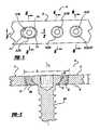
- Figure 1is a top view of a plating system according to the present invention.
- Figure 2is a cross-sectional view taken along the line 2-2 of Figure 1 .
- Figure 3is a cross-sectional view taken along the line 3-3 of Figure 1 .
- Figure 4is a cross-sectional view taken along the line 4-4 of Figure 1 .
- Figure 5is a cross-sectional view similar to Figure 4 , the bone screw shown angulated from the orientation illustrated in Figure 4 .
- Figure 6is a cross-sectional view taken along the line 6-6 of Figure 1 .
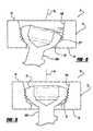
- Figure 7is a cross-sectional view similar to Figure 3A , illustrating a bone screw with an unthreaded head.
- Figure 8is a cross-sectional view similar to Figure 6 , illustrating a collar formed with threads to engage the threads of the plate member.
- Figure 9is a cross-sectional view similar to Figure 3 , illustrating the first bone screw angulated relative to the plate member.
- a bone plating system constructed in accordance with the teachings of the present inventionis illustrated and generally identified at reference character 10.
- the teachings of the present inventionare specifically intended for a plating system that can be used to stabilize bone portions of the proximal femur, distal tibia and proximal tibia, for example. It will become apparent to those skilled in the art, however, that the teachings of the present invention are also suitable for various other applications in which surgical repair of bone with a plate is desired. Other applications include but are not limited to the distal radius and the spine.
- the bone plating system 10is illustrated to generally include a plate member 12.
- the plate member 12may be flat or may be contoured for specific applications in a manner well known in the art to conform with a bone.
- the plate member 12is generally shown to include an upper surface 14 and a lower surface 16.
- the plate member 12may be constructed of any suitable biocompatible material.
- One exemplary materialis a titanium alloy such as Ti6Al4V.
- Other materials having acceptable strength characteristics, including but not limited to stainless steel,may also be employed.
- the plate member 12defines a thickness t between the upper surface 14 and the lower surface 16.
- the thickness tmay be constant throughout the plate member 12 or may be variable.
- the plate member 12has an approximate thickness between 2.0 and 5.0 mm. More preferably, this particular plate member 12 has a thickness of approximately 2.0 mm.
- the plate member 12in which the plate member 12 is constructed of stainless steel and intended for stabilizing the distal radius, the plate member 12 has an approximate thickness between 1.5 and 2.0 mm, and more preferably has a thickness of approximately 1.5 mm. It should be readily apparent that the plate thickness t may vary according to material choices and strength requirements.
- the plate member 12is illustrated to define a plurality of holes 18 for receiving bone screws 20 for securing the plate member 12 to a bone (not specifically shown).
- the plate member 12is shown in Figure 1 to include three holes 18. It will be understood that the particular number of holes 18 defined by the plate member 12 and the specific types of holes 18 may vary within the scope of the present invention and largely depend on the intended application for the plating system 10.
- the plurality of holes 18 defined by the plate member 12includes a first hole 18A.
- the first hole 18Ais an elongated hole having circular end portions 52 and is shown in the cross-sectional views of Figures 2 and 3 receiving a first bone screw on fastener 20A of the plurality of bone screws 20.
- the bone screw 20Ahas a longitudinal axis A 1 oriented in Figures 2 and 3 generally perpendicular to a plane defined by the plate member 12.
- the first bone screw 20Ais shown to include a threaded shaft for engaging bone.
- the shaft of the bone screws 20can be conventional in construction.
- the first hole 18Aextends between the top surface 14 and the bottom surface 16 in the direction of the axis A 1 (as shown in Figure 2 , for example). Given the particular orientation of the bone screw 20A, the axis [[A]] A 1 , is coincident with a longitudinal axis of the bone screw 20A.
- the first hole 18Ahas a first dimension D 1 adjacent the upper surface 14 in a first direction generally perpendicular to the axis A 1 .
- the first hole 18Aincludes a second dimension D 2 adjacent the upper surface 14 in a second direction generally perpendicular to the axis A 1 and perpendicular to the first dimension D 1 and to the longitudinal axis of the plate member 12 .
- the first dimension D 1is substantially greater than the second dimension D 2 .
- the first hole 18Ais elongated along the length of the plate member 12 and the first and second dimensions D 1 and D 2 correspond to a length and a width of the hole 18A, respectively.
- the first dimension D 1is approximately 7.25 mm and the second dimension D 2 is approximately 10.0 mm.
- the plate member 12is threaded. More particularly, the plate member 12 is shown to include at least one ridge 22 on an inner circumferential surface 50 of the first hole 18A, the ridge extending completely about an inner circumference, and thereby forming a closed loop.
- the plate member 12may include a plurality of ridges 22. In the embodiment illustrated, the ridges 22 are formed parallel to one another and are each oriented generally parallel to the plane defined by the plate member 12. The minor diameters of the ridges 22 define an effective opening having a circular shape.
- the circular ridges 22are configured to cooperate with a spherically shaped head of a bone screw.
- the first bone screw 20Awhich is shown particularly in Figures 2 and 3 , is illustrated to include a spherically shaped threaded head 24 for engaging the ridges 22.
- Engagement of the threaded head 24 with the ridges 22functions to orient the bone screw 20A relative to the plate member 12 and to fix the bone screw 20A relative to the plate member 12.
- the bone screw 20Ais resultingly oriented with its longitudinal axis A 1 generally perpendicular to the plane defined by the plate member 12.
- the head 24 of the first bone screw 20Aincludes a double lead thread 26.
- the ridges 22 of the plate member 12can be replaced with a helical thread (not shown with respect to the first hole 18A) for threadably engaging the head 24.
- the bone screws 20Awould correspondingly be fixed to the plate member 12 at an angle.
- certain applicationsmay require convergence of two or more bone screws 20 at fixed angles.
- the first hole 18Ais also particularly adapted to receive a second bone screw 20B having a head 28 without threads.
- the head 28 of the second bone screw 20Bis generally spherical in the shape. This spherical shape of the head 28 cooperates with the ridges 22 to allow the second bone screw 20B to angulate relative to the plate member 12.
- the second bone screw 20Bcan be engaged with the bone at a variable angle.
- the elongated shape of the first hole 18Aprovides a surgeon with increased flexibility for bone screw placement.
- the surgeonmay position the bone screw 20A or 20B anywhere along the length of the first hole 18A in a direction of the first dimension D 1 .
- This flexibility in positioning of bone screws 20A or 20B relative to the plate member 12is available regardless of whether the surgeon elects to use a bone screw 20A having a threaded head 24 for establishing a fixed relationship between the plate member 12 and the bone screw 20A at a predetermined angle, or a bone screw 20B having an unthreaded head 28 that allows angulation relative to the plate member 12.
- the elongated shape of the first hole 18Aadditionally allows the surgeon to compress a fracture of the bone by translating the bone screw 20 along the hole 18A in a direction parallel to D 1 .
- the circular ridges 22permit such translation even where a threaded head is used, thereby retaining the locking relationship between the plate member 12 and the bone screw 20.
- Translation of the bone screw 20is manually accomplished with an insertion tool (e.g., screw driver) that engages the head.
- an insertion toole.g., screw driver
- the surgeonlinearly advances the screw 20 along the hole 18A with the insertion tool.
- a non-threaded head of a bone screw 20would engage an end of the hole 18A and compress the bone as the non-threaded head transitions past the angled end of the hole 18A.
- a second hole defined by the plate member 12is illustrated.
- the second hole 20Bis generally circular in shape.
- the hole 20Bhas an upper diameter D 3 at the upper surface 14 of the plate member 12 and a smaller diameter D 4 at the lower surface 16 of the plate member 12.
- the second hole 20Bincludes a spherically shaped portion 30 having a plurality of threads 32.
- the plate member 12can be formed with a plurality of circular ridges similar to the ridges 22 shown and described in connection with the first hole 18A.
- Figures 4 and 5illustrate the second hole 20B operatively associated with a bone screw 20B identical to the bone screw 20B discussed above.
- Figure 4illustrates the second bone screw 20B with its longitudinal axis oriented generally perpendicular to the plane defined by the plate member 12 immediately prior to seating of the spherical head 28 on the threads 32.
- Figure 5illustrates the bone screw 20B seated with its spherical head 28 seated on the threads 32 and the bone screw 20B with its longitudinal axis articulated from the perpendicular orientation shown in Figure 4 .
- the spherical shape of the head and the cooperating shape of the threads 32allow the bone screw 20B to articulate from the orientation shown in Figure 4 approximately 15° in any direction.
- a third hole 20C defined by the plate member 12is illustrated. It will be understood that the third hole 20C and the threads 32 associated with the third hole 20C are identical to the second hole 20B and corresponding threads 32 discussed above.
- the third hole 20Cis illustrated with a bone screw 20A having a threaded head 24.
- the bone screw 20Ais identical to the bone screw 20A discussed above. In the manner discussed above, the threaded head 24 and the threaded hole 20C cooperate for fixedly securing the bone screw 20A8 to the plate member 12.
- the bone screw 20Ais secured to the plate with the longitudinal axis A 1 of the bone screw 20A oriented generally perpendicular to the plane defined by the plate member 12.
- the third hole 18C of the plate member 12is shown operatively associated with a third bone screw 20C.
- the third bone screw 20Cis illustrated to include a threaded shaft portion 36 for threadably engaging a bone and a head portion 38.
- the third bone screw 20Cis further shown to include a collar 40.
- the collar 40defines an aperture 42 for receiving the head 38 of the third bone screw 20C.
- the collar 40further includes an outer threaded surface 44 which is spherical in shape.
- the outer threaded surface 44cooperates with the threads 32 of the hole 18C substantially in the manner discussed above with respects to Figure 6 .
- the collar 40maintains a locking connection with the plate member 12 while allowing the plate member 12 to be drawn adjacent the bone. In this manner, the profile of the plate member 12 may be minimized.
- FIG. 9a cross-sectional view similar to Figure 3 is illustrated.
- the bone screw 20Ais angled from a perpendicular orientation. Such angulation of the bone screw 20A is permitted despite the threaded engagement between the head and the plate member 12 due to the double-lead thread of the head and the circular ridges 22 of the plate member 12.
- the double lead thread and the ridges 22allow for angulation in increments of approximately 5° to 10° from the perpendicular orientation of Figure 3 .
- a plate membermay be constructed to include all elongated holes 18A. It is further anticipated that the various teachings of the present invention may be utilized separately in any combination to stabilize both long bones (including but not limited to the femur, the tibia, and the radius) and vertebral bodies.
Landscapes
- Health & Medical Sciences (AREA)
- Orthopedic Medicine & Surgery (AREA)
- Surgery (AREA)
- Life Sciences & Earth Sciences (AREA)
- Heart & Thoracic Surgery (AREA)
- Nuclear Medicine, Radiotherapy & Molecular Imaging (AREA)
- Engineering & Computer Science (AREA)
- Biomedical Technology (AREA)
- Neurology (AREA)
- Medical Informatics (AREA)
- Molecular Biology (AREA)
- Animal Behavior & Ethology (AREA)
- General Health & Medical Sciences (AREA)
- Public Health (AREA)
- Veterinary Medicine (AREA)
- Surgical Instruments (AREA)
Description
- The present invention relates generally to orthopedic surgical procedures. More particularly, the present invention relates to a bone plating system. The features of the preamble of claim 1 are known from the document
DE-U-203 17 651 . - In certain orthopedic surgical procedures, it is necessary to secure multiple bones or bone portions relative to each other to facilitate proper healing. For example, it is frequently necessary to secure two or more portions of a broken long bone such as the tibia to ensure proper healing. This need may be the result of physical trauma from fractures or dislocations, degenerative diseases, or tumors. Improper mending of the bone may result in deformity, discomfort or both.
- Common methods of fracture treatment include casting and external fixation. It is also well known to treat fractures with internal plating systems. Use of such plating systems involves the attachment of a plate to the bone with bone screws. The plating systems function to stabilize discrete bone portions and thereby facilitate fusion of the bone portions in a particular orientation for healing or to repair a condition of the patient.
- Various plating systems are known. One known plating system is shown in German utility model
DE 93 21 544 U1 . This German utility model illustrates a plating system having a plate member with a shaft portion and a head portion. The head portion is configured to conform to a metaphysis of a bone and includes a plurality of internally threaded holes. The threads of the holes engage threaded heads of bone screws. The shaft portion is shown to include two round holes and an elongated slot. The holes and slot of the shaft portion are unthreaded for receiving bone screws with unthreaded heads. - It remains desirable to continuously improve the pertinent art.
- The present invention relates to a plating system for bone as claimed in claim 1.
- Additional advantages and further areas of applicability of the present invention will become apparent from the detailed description and appended claims provided hereinafter. It should be understood that the detailed description and specific examples, while indicating the preferred embodiment of the invention, are intended for purposes of illustration only and are not intended to limit the scope of the invention which is defined by the appended claims.
- The present invention will become more fully understood from the detailed description and the accompanying drawings, wherein:
Figure 1 is a top view of a plating system according to the present invention.Figure 2 is a cross-sectional view taken along the line 2-2 ofFigure 1 .Figure 3 is a cross-sectional view taken along the line 3-3 ofFigure 1 .Figure 4 is a cross-sectional view taken along the line 4-4 ofFigure 1 .Figure 5 is a cross-sectional view similar toFigure 4 , the bone screw shown angulated from the orientation illustrated inFigure 4 .Figure 6 is a cross-sectional view taken along the line 6-6 ofFigure 1 .Figure 7 is a cross-sectional view similar toFigure 3A , illustrating a bone screw with an unthreaded head.Figure 8 is a cross-sectional view similar toFigure 6 , illustrating a collar formed with threads to engage the threads of the plate member.Figure 9 is a cross-sectional view similar toFigure 3 , illustrating the first bone screw angulated relative to the plate member.- The following description of embodiments of the present invention will be understood to be merely exemplary in nature and is in no way intended to limit the invention, its application, or uses.
- With reference to
Figures 1 through 9 of the drawings a bone plating system constructed in accordance with the teachings of the present invention is illustrated and generally identified atreference character 10. In certain applications, the teachings of the present invention are specifically intended for a plating system that can be used to stabilize bone portions of the proximal femur, distal tibia and proximal tibia, for example. It will become apparent to those skilled in the art, however, that the teachings of the present invention are also suitable for various other applications in which surgical repair of bone with a plate is desired. Other applications include but are not limited to the distal radius and the spine. - The
bone plating system 10 is illustrated to generally include aplate member 12. Theplate member 12 may be flat or may be contoured for specific applications in a manner well known in the art to conform with a bone. Theplate member 12 is generally shown to include anupper surface 14 and alower surface 16. Theplate member 12 may be constructed of any suitable biocompatible material. One exemplary material is a titanium alloy such as Ti6Al4V. Other materials having acceptable strength characteristics, including but not limited to stainless steel, may also be employed. - The
plate member 12 defines a thickness t between theupper surface 14 and thelower surface 16. The thickness t may be constant throughout theplate member 12 or may be variable. In one particular application in which theplate member 12 is constructed of Ti6Al4V and intended for stabilizing the proximal tibia, theplate member 12 has an approximate thickness between 2.0 and 5.0 mm. More preferably, thisparticular plate member 12 has a thickness of approximately 2.0 mm. In another particular application, in which theplate member 12 is constructed of stainless steel and intended for stabilizing the distal radius, theplate member 12 has an approximate thickness between 1.5 and 2.0 mm, and more preferably has a thickness of approximately 1.5 mm. It should be readily apparent that the plate thickness t may vary according to material choices and strength requirements. - The
plate member 12 is illustrated to define a plurality of holes 18 for receiving bone screws 20 for securing theplate member 12 to a bone (not specifically shown). For purposes of illustration, theplate member 12 is shown inFigure 1 to include three holes 18. It will be understood that the particular number of holes 18 defined by theplate member 12 and the specific types of holes 18 may vary within the scope of the present invention and largely depend on the intended application for theplating system 10. - With particular reference to
Figures 1-3 , the plurality of holes 18 defined by theplate member 12 includes afirst hole 18A. Thefirst hole 18A is an elongated hole havingcircular end portions 52 and is shown in the cross-sectional views ofFigures 2 and3 receiving a first bone screw onfastener 20A of the plurality of bone screws 20. Thebone screw 20A has a longitudinal axis A1 oriented inFigures 2 and3 generally perpendicular to a plane defined by theplate member 12. Thefirst bone screw 20A is shown to include a threaded shaft for engaging bone. The shaft of the bone screws 20 can be conventional in construction. - The
first hole 18A extends between thetop surface 14 and thebottom surface 16 in the direction of the axis A1 (as shown inFigure 2 , for example). Given the particular orientation of thebone screw 20A, the axis [[A]]A1, is coincident with a longitudinal axis of thebone screw 20A. Thefirst hole 18A has a first dimension D1 adjacent theupper surface 14 in a first direction generally perpendicular to the axis A1. Thefirst hole 18A includes a second dimension D2 adjacent theupper surface 14 in a second direction generally perpendicular to the axis A1and perpendicular to the first dimension D1and to the longitudinal axis of theplate member 12. The first dimension D1 is substantially greater than the second dimension D2. In the embodiment illustrated, thefirst hole 18A is elongated along the length of theplate member 12 and the first and second dimensions D1 and D2 correspond to a length and a width of thehole 18A, respectively. In one particular application, the first dimension D1 is approximately 7.25 mm and the second dimension D2 is approximately 10.0 mm. - As shown, particularly in
Figures 2 and3 , theplate member 12 is threaded. More particularly, theplate member 12 is shown to include at least oneridge 22 on an innercircumferential surface 50 of thefirst hole 18A, the ridge extending completely about an inner circumference, and thereby forming a closed loop. Theplate member 12 may include a plurality ofridges 22. In the embodiment illustrated, theridges 22 are formed parallel to one another and are each oriented generally parallel to the plane defined by theplate member 12. The minor diameters of theridges 22 define an effective opening having a circular shape. - The
circular ridges 22 are configured to cooperate with a spherically shaped head of a bone screw. For example, thefirst bone screw 20A, which is shown particularly inFigures 2 and3 , is illustrated to include a spherically shaped threadedhead 24 for engaging theridges 22. Engagement of the threadedhead 24 with theridges 22 functions to orient thebone screw 20A relative to theplate member 12 and to fix thebone screw 20A relative to theplate member 12. Given the orientation of the circular ridges, thebone screw 20A is resultingly oriented with its longitudinal axis A1 generally perpendicular to the plane defined by theplate member 12. In the embodiment illustrated, thehead 24 of thefirst bone screw 20A includes adouble lead thread 26. Alternatively, theridges 22 of theplate member 12 can be replaced with a helical thread (not shown with respect to thefirst hole 18A) for threadably engaging thehead 24. - In certain applications, it may be desired to orient the
ridges 22 at an angle relative to the plane of theplate member 12. In such alternative applications, the bone screws 20A would correspondingly be fixed to theplate member 12 at an angle. For example, certain applications may require convergence of two or more bone screws 20 at fixed angles. - As shown in the cross-sectional view of
Figure 7 , thefirst hole 18A is also particularly adapted to receive asecond bone screw 20B having ahead 28 without threads. Thehead 28 of thesecond bone screw 20B is generally spherical in the shape. This spherical shape of thehead 28 cooperates with theridges 22 to allow thesecond bone screw 20B to angulate relative to theplate member 12. In this regard, as compared to the fixed relationship established with the threadedhead 28 of thefirst bone screw 20A (as shown inFigures 2 and3 ) thesecond bone screw 20B can be engaged with the bone at a variable angle. - The elongated shape of the
first hole 18A provides a surgeon with increased flexibility for bone screw placement. In this regard, the surgeon may position thebone screw first hole 18A in a direction of the first dimension D1. This flexibility in positioning ofbone screws plate member 12 is available regardless of whether the surgeon elects to use abone screw 20A having a threadedhead 24 for establishing a fixed relationship between theplate member 12 and thebone screw 20A at a predetermined angle, or abone screw 20B having an unthreadedhead 28 that allows angulation relative to theplate member 12. - The elongated shape of the
first hole 18A additionally allows the surgeon to compress a fracture of the bone by translating the bone screw 20 along thehole 18A in a direction parallel to D1. Thecircular ridges 22 permit such translation even where a threaded head is used, thereby retaining the locking relationship between theplate member 12 and the bone screw 20. Translation of the bone screw 20 is manually accomplished with an insertion tool (e.g., screw driver) that engages the head. Explaining further, the surgeon linearly advances the screw 20 along thehole 18A with the insertion tool. In certain alternative applications, it may be desirable to automatically compress the bone by angling the ends of thehole 18A. In such applications, a non-threaded head of a bone screw 20 would engage an end of thehole 18A and compress the bone as the non-threaded head transitions past the angled end of thehole 18A. - With particular reference to the cross-sectional view of
Figure 4 , a second hole defined by theplate member 12 is illustrated. As compared to thefirst hole 28, thesecond hole 20B is generally circular in shape. Thehole 20B has an upper diameter D3 at theupper surface 14 of theplate member 12 and a smaller diameter D4 at thelower surface 16 of theplate member 12. Between theupper surface 14 and thelower surface 16 thesecond hole 20B includes a spherically shapedportion 30 having a plurality ofthreads 32. Alternatively, it will be understood that theplate member 12 can be formed with a plurality of circular ridges similar to theridges 22 shown and described in connection with thefirst hole 18A. Figures 4 and5 illustrate thesecond hole 20B operatively associated with abone screw 20B identical to thebone screw 20B discussed above.Figure 4 illustrates thesecond bone screw 20B with its longitudinal axis oriented generally perpendicular to the plane defined by theplate member 12 immediately prior to seating of thespherical head 28 on thethreads 32.Figure 5 illustrates thebone screw 20B seated with itsspherical head 28 seated on thethreads 32 and thebone screw 20B with its longitudinal axis articulated from the perpendicular orientation shown inFigure 4 . It will be appreciated that the spherical shape of the head and the cooperating shape of thethreads 32 allow thebone screw 20B to articulate from the orientation shown inFigure 4 approximately 15° in any direction.- With particular reference to the cross-sectional view of
Figure 6 , athird hole 20C defined by theplate member 12 is illustrated. It will be understood that thethird hole 20C and thethreads 32 associated with thethird hole 20C are identical to thesecond hole 20B andcorresponding threads 32 discussed above. Thethird hole 20C is illustrated with abone screw 20A having a threadedhead 24. Thebone screw 20A is identical to thebone screw 20A discussed above. In the manner discussed above, the threadedhead 24 and the threadedhole 20C cooperate for fixedly securing the bone screw 20A8 to theplate member 12. Thebone screw 20A is secured to the plate with the longitudinal axis A1 of thebone screw 20A oriented generally perpendicular to the plane defined by theplate member 12. - Turning to
Figure 8 , thethird hole 18C of theplate member 12 is shown operatively associated with athird bone screw 20C. Thethird bone screw 20C is illustrated to include a threadedshaft portion 36 for threadably engaging a bone and ahead portion 38. Thethird bone screw 20C is further shown to include acollar 40. Thecollar 40 defines anaperture 42 for receiving thehead 38 of thethird bone screw 20C. Thecollar 40 further includes an outer threadedsurface 44 which is spherical in shape. The outer threadedsurface 44 cooperates with thethreads 32 of thehole 18C substantially in the manner discussed above with respects toFigure 6 . Thecollar 40 maintains a locking connection with theplate member 12 while allowing theplate member 12 to be drawn adjacent the bone. In this manner, the profile of theplate member 12 may be minimized. - With particular reference to
Figure 9 , a cross-sectional view similar toFigure 3 is illustrated. InFigure 9 , however, thebone screw 20A is angled from a perpendicular orientation. Such angulation of thebone screw 20A is permitted despite the threaded engagement between the head and theplate member 12 due to the double-lead thread of the head and thecircular ridges 22 of theplate member 12. - In the embodiment illustrated, the double lead thread and the
ridges 22 allow for angulation in increments of approximately 5° to 10° from the perpendicular orientation ofFigure 3 . - The teachings of the present invention have now been described to include various types of plate member holes and various types of bone screws. It is readily anticipated that the different holes and different bone screws can be combined alternatively for particular applications. Further in this regard, it is anticipated that certain applications may only include one type of hole. For example, a plate member may be constructed to include all
elongated holes 18A. It is further anticipated that the various teachings of the present invention may be utilized separately in any combination to stabilize both long bones (including but not limited to the femur, the tibia, and the radius) and vertebral bodies. - The description of the invention is merely exemplary in nature and, thus, variations that do not depart from the scope of the appended claims are intended to be within the scope of the invention.
Claims (8)
- A plating system (10) for bone, the plating system (10) comprising:a plate member (12) having a top surface (14) and a bottom surface (16);a plurality of holes (18) defined by the plate member (12) extending between the top surface (14) and the bottom surface (16) along a hole axis, at least a first hole (18A) of the plurality of holes having threads extending completely about an inner circumference,characterised by the first hole (18A) having a first dimension (D1) generally perpendicular to the hole axis and a second dimension (D2) generally perpendicular to the hole axis, the first dimension being greater than the second dimension, so that the first hole (18A) has an elongated shape; the plating system further comprising a bone screw (20A), whereby the elongated shape of the first hole (18A) enables positioning of the bone screw (20A) anywhere along the lengths of the first hole (18A) in a direction of the first dimension (D1) and whereby the bone screw has an externally threaded spherical head threadably engaging the first hole (18A).
- The plating system (10) for bone of Claim 1, wherein the first hole (18A) includes at least one ridge (22) extending completely about the inner circumference.
- The plating system (10) for bone of Claim 2, wherein the first hole (18A) includes a plurality of circular ridges (22) extending completely about the inner circumference.
- The plating system (10) for bone of Claim 2, wherein the head includes a double lead thread engaging the at least one ridge (22).
- The plating system for bone of Claim 5, wherein the at least one ridge (22) is oriented generally perpendicular to the axis and the bone screw (20A) has a longitudinal axis angled relative to the hole axis.
- The plating system (10) for bone of Claim 1, further comprising a second bone screw (20), which bone screw (20) has a shaft extending below the plate member (12) and a head disposed in a second hole (18C), the head being spherical, the head including a modular collar, the collar (40) having an outer spherical surface (44) threadably engaging the second hole (18C) of the plurality of holes (18), the second hole (18C) having a spherical and threaded inner surface.
- The plating system of claim 6 wherein the second hole (18C) is helically threaded.
- The plating system according to any of the preceding claims, wherein the plurality of holes are aligned to lie on an imaginary straight line extending longitudinally along the plate member.
Applications Claiming Priority (2)
| Application Number | Priority Date | Filing Date | Title |
|---|---|---|---|
| US865248 | 2004-06-10 | ||
| US10/865,248US20050277937A1 (en) | 2004-06-10 | 2004-06-10 | Bone plating system |
Publications (2)
| Publication Number | Publication Date |
|---|---|
| EP1604619A1 EP1604619A1 (en) | 2005-12-14 |
| EP1604619B1true EP1604619B1 (en) | 2012-08-08 |
Family
ID=34937366
Family Applications (1)
| Application Number | Title | Priority Date | Filing Date |
|---|---|---|---|
| EP05012522AExpired - LifetimeEP1604619B1 (en) | 2004-06-10 | 2005-06-10 | Bone plating system |
Country Status (3)
| Country | Link |
|---|---|
| US (2) | US20050277937A1 (en) |
| EP (1) | EP1604619B1 (en) |
| ES (1) | ES2392720T3 (en) |
Cited By (5)
| Publication number | Priority date | Publication date | Assignee | Title |
|---|---|---|---|---|
| US7794493B2 (en) | 2004-06-30 | 2010-09-14 | Cordis Corporation | Magnetic resonance imaging compatibility alloy for implantable medical devices |
| US8343196B2 (en) | 2003-08-26 | 2013-01-01 | Synthes Usa, Llc | Bone plate |
| US8574268B2 (en) | 2004-01-26 | 2013-11-05 | DePuy Synthes Product, LLC | Highly-versatile variable-angle bone plate system |
| US8758346B2 (en) | 2009-09-14 | 2014-06-24 | DePuy Synthes Products, LLC | Variable angle compression plate |
| US9168075B2 (en) | 2004-01-26 | 2015-10-27 | DePuy Synthes Products, Inc. | Variable angle locked bone fixation system |
Families Citing this family (63)
| Publication number | Priority date | Publication date | Assignee | Title |
|---|---|---|---|---|
| US7776076B2 (en)* | 2004-05-11 | 2010-08-17 | Synthes Usa, Llc | Bone plate |
| US7951176B2 (en) | 2003-05-30 | 2011-05-31 | Synthes Usa, Llc | Bone plate |
| US11259851B2 (en) | 2003-08-26 | 2022-03-01 | DePuy Synthes Products, Inc. | Bone plate |
| US8105367B2 (en) | 2003-09-29 | 2012-01-31 | Smith & Nephew, Inc. | Bone plate and bone plate assemblies including polyaxial fasteners |
| US8182485B1 (en) | 2003-11-21 | 2012-05-22 | Toby Orthopaedics, Llc | Fracture fixation system |
| US11291484B2 (en) | 2004-01-26 | 2022-04-05 | DePuy Synthes Products, Inc. | Highly-versatile variable-angle bone plate system |
| US20060058796A1 (en)* | 2004-09-14 | 2006-03-16 | Hartdegen Vernon R | Compression brace |
| DE102005004841B4 (en)* | 2004-12-30 | 2009-10-29 | Königsee Implantate und Instrumente zur Osteosynthese GmbH | Osteosynthesis plate with a variety of holes for receiving bone screws |
| CA2616798C (en) | 2005-07-25 | 2014-01-28 | Smith & Nephew, Inc. | Systems and methods for using polyaxial plates |
| US8382807B2 (en) | 2005-07-25 | 2013-02-26 | Smith & Nephew, Inc. | Systems and methods for using polyaxial plates |
| US7955364B2 (en)* | 2005-09-21 | 2011-06-07 | Ebi, Llc | Variable angle bone fixation assembly |
| US7951178B2 (en)* | 2006-04-03 | 2011-05-31 | Acumed Llc | Bone plates with hybrid apertures |
| DE102006031801A1 (en)* | 2006-07-06 | 2008-01-10 | Aap Implantate Ag | Osteosynthesis fixation system |
| US8361130B2 (en) | 2006-10-06 | 2013-01-29 | Depuy Spine, Inc. | Bone screw fixation |
| US8066750B2 (en)* | 2006-10-06 | 2011-11-29 | Warsaw Orthopedic, Inc | Port structures for non-rigid bone plates |
| US20080234749A1 (en)* | 2007-01-26 | 2008-09-25 | Zimmer Technology, Inc. | Bone plate providing threaded locking head screw capture |
| US8636779B2 (en)* | 2007-02-26 | 2014-01-28 | Life Spine, Inc. | Spine plate with configured bone screw bores |
| US8702762B2 (en) | 2007-03-27 | 2014-04-22 | Depuy Spine, Inc. | Passive screw locking mechanism |
| US20090216282A1 (en)* | 2007-05-18 | 2009-08-27 | Blake Doris M | Systems and methods for retaining a plate to a substrate with an asynchronous thread form |
| US8556944B2 (en)* | 2007-07-31 | 2013-10-15 | Stryker Spine | System and method for vertebral body plating |
| US8388666B2 (en)* | 2007-09-27 | 2013-03-05 | Biomet C.V. | Locking screw system with relatively hard spiked polyaxial bushing |
| US8282675B2 (en) | 2008-01-25 | 2012-10-09 | Depuy Spine, Inc. | Anti-backout mechanism |
| US20090228010A1 (en) | 2008-03-10 | 2009-09-10 | Eduardo Gonzalez-Hernandez | Bone fixation system |
| AU2008354730A1 (en) | 2008-04-17 | 2009-10-22 | Toby Orthopaedics, Inc. | Soft tissue attachment system and clip |
| US10251757B2 (en)* | 2008-09-17 | 2019-04-09 | Skeletal Dynamics Llc | Grooved slot allowing adjustment of the position of a bone fixation device for osteosynthesis |
| FR2936700B1 (en) | 2008-10-02 | 2012-04-13 | Memometal Technologies | ORTHOPEDIC IMPLANT IN THE FORM OF A PLATE TO BE FIXED BETWEEN TWO BONE PARTS |
| EP2248479B1 (en) | 2009-05-06 | 2012-09-19 | Greatbatch Ltd. | Bone plate assembly |
| US9259255B2 (en) | 2009-07-15 | 2016-02-16 | Orthohelix Surgical Designs, Inc. | Variable axis locking mechanism for use in orthopedic implants |
| US8496692B2 (en) | 2009-09-21 | 2013-07-30 | Jmea Corporation | Locking securing member |
| CN102740786A (en)* | 2009-12-22 | 2012-10-17 | 托比骨科有限公司 | Bone plate and tool assembly and method for use thereof |
| US8486116B2 (en) | 2010-01-08 | 2013-07-16 | Biomet Manufacturing Ring Corporation | Variable angle locking screw |
| EP2364657B1 (en)* | 2010-03-08 | 2012-05-09 | Stryker Trauma SA | Bone fixation system with curved profile threads |
| US20110218580A1 (en)* | 2010-03-08 | 2011-09-08 | Stryker Trauma Sa | Bone fixation system with curved profile threads |
| US9113970B2 (en) | 2010-03-10 | 2015-08-25 | Orthohelix Surgical Designs, Inc. | System for achieving selectable fixation in an orthopedic plate |
| US8961573B2 (en) | 2010-10-05 | 2015-02-24 | Toby Orthopaedics, Inc. | System and method for facilitating repair and reattachment of comminuted bone portions |
| WO2012058448A2 (en) | 2010-10-27 | 2012-05-03 | Toby Orthopaedics, Llc | System and method for fracture replacement of comminuted bone fractures or portions thereof adjacent bone joints |
| EP2460484A1 (en)* | 2010-12-01 | 2012-06-06 | FACET-LINK Inc. | Variable angle bone screw fixation assembly |
| US8728129B2 (en) | 2011-01-07 | 2014-05-20 | Biomet Manufacturing, Llc | Variable angled locking screw |
| WO2012119146A2 (en) | 2011-03-03 | 2012-09-07 | Toby Orthopaedics, Llc | Anterior lesser tuberosity fixed angle fixation device and method of use associated therewith |
| US20120232599A1 (en)* | 2011-03-10 | 2012-09-13 | Jared Schoenly | Awl screw fixation members and related systems |
| US20140330320A1 (en)* | 2011-05-17 | 2014-11-06 | Dietmar Wolter | Bone Plate |
| US8771324B2 (en) | 2011-05-27 | 2014-07-08 | Globus Medical, Inc. | Securing fasteners |
| AU2012271441B2 (en) | 2011-06-15 | 2017-02-02 | Smith & Nephew, Inc. | Variable angle locking implant |
| US9730797B2 (en) | 2011-10-27 | 2017-08-15 | Toby Orthopaedics, Inc. | Bone joint replacement and repair assembly and method of repairing and replacing a bone joint |
| US9271772B2 (en) | 2011-10-27 | 2016-03-01 | Toby Orthopaedics, Inc. | System and method for fracture replacement of comminuted bone fractures or portions thereof adjacent bone joints |
| US9402667B2 (en) | 2011-11-09 | 2016-08-02 | Eduardo Gonzalez-Hernandez | Apparatus and method for use of the apparatus for fracture fixation of the distal humerus |
| US9283008B2 (en) | 2012-12-17 | 2016-03-15 | Toby Orthopaedics, Inc. | Bone plate for plate osteosynthesis and method for use thereof |
| US9107711B2 (en) | 2013-02-20 | 2015-08-18 | Stryker Trauma Sa | Screw thread with flattened peaks |
| US9333014B2 (en) | 2013-03-15 | 2016-05-10 | Eduardo Gonzalez-Hernandez | Bone fixation and reduction apparatus and method for fixation and reduction of a distal bone fracture and malunion |
| US9510880B2 (en)* | 2013-08-13 | 2016-12-06 | Zimmer, Inc. | Polyaxial locking mechanism |
| DE102014117175A1 (en)* | 2014-11-24 | 2016-05-25 | Aesculap Ag | Pedicle screw system and spine stabilization system |
| GB2557840B (en) | 2015-09-18 | 2021-07-21 | Smith & Nephew Inc | Bone plate |
| US10624686B2 (en) | 2016-09-08 | 2020-04-21 | DePuy Synthes Products, Inc. | Variable angel bone plate |
| US10820930B2 (en) | 2016-09-08 | 2020-11-03 | DePuy Synthes Products, Inc. | Variable angle bone plate |
| US10905476B2 (en) | 2016-09-08 | 2021-02-02 | DePuy Synthes Products, Inc. | Variable angle bone plate |
| US11026727B2 (en) | 2018-03-20 | 2021-06-08 | DePuy Synthes Products, Inc. | Bone plate with form-fitting variable-angle locking hole |
| US10772665B2 (en) | 2018-03-29 | 2020-09-15 | DePuy Synthes Products, Inc. | Locking structures for affixing bone anchors to a bone plate, and related systems and methods |
| US11013541B2 (en) | 2018-04-30 | 2021-05-25 | DePuy Synthes Products, Inc. | Threaded locking structures for affixing bone anchors to a bone plate, and related systems and methods |
| US10925651B2 (en) | 2018-12-21 | 2021-02-23 | DePuy Synthes Products, Inc. | Implant having locking holes with collection cavity for shavings |
| IT201900002119A1 (en)* | 2019-02-13 | 2020-08-13 | Vese Silvana | Device for osteosynthesis |
| FR3092743B1 (en)* | 2019-02-14 | 2021-11-12 | Newclip Int | Plate osteosynthesis device with an oblong hole for receiving a fixing screw |
| AU2020291005A1 (en) | 2019-06-12 | 2022-01-20 | Government Of The United States Of America As Represented By The Department Of Veterans Affairs | Femoral head arthroplasty system |
| IL298696A (en)* | 2020-06-04 | 2023-02-01 | Trace Orthopedics Llc | Dual-functional anchoring system |
Family Cites Families (50)
| Publication number | Priority date | Publication date | Assignee | Title |
|---|---|---|---|---|
| US28841A (en)* | 1860-06-26 | Josiah p | ||
| US14808A (en)* | 1856-05-06 | Improved self-regulating windmill | ||
| US531745A (en)* | 1895-01-01 | Short-turning gear for wagons | ||
| US472913A (en)* | 1892-04-12 | Nail or spike | ||
| US470588A (en)* | 1892-03-08 | Fertilizer-distributer | ||
| US443060A (en)* | 1890-12-16 | Bridge | ||
| US3645161A (en)* | 1969-11-18 | 1972-02-29 | Pic Design Corp | Solder tip setscrew |
| US3716050A (en)* | 1971-02-11 | 1973-02-13 | F Johnston | Olecranon plate |
| CH645013A5 (en)* | 1980-04-14 | 1984-09-14 | Wenk Wilh Ag | Osteosynthetic COMPRESSION PLATE. |
| FR2515859A1 (en)* | 1981-10-29 | 1983-05-06 | Crouzet Sa | ELECTROMAGNETIC CYLINDER DEBRAYABLE |
| US4465065A (en)* | 1983-01-07 | 1984-08-14 | Yechiel Gotfried | Surgical device for connection of fractured bones |
| US5190544A (en)* | 1986-06-23 | 1993-03-02 | Pfizer Hospital Products Group, Inc. | Modular femoral fixation system |
| US5006120A (en)* | 1989-10-10 | 1991-04-09 | Carter Peter R | Distal radial fracture set and method for repairing distal radial fractures |
| US5304180A (en)* | 1992-01-17 | 1994-04-19 | Slocum D Barclay | Tibial osteotomy fixation plate |
| US5531745A (en)* | 1993-03-11 | 1996-07-02 | Danek Medical, Inc. | System for stabilizing the spine and reducing spondylolisthesis |
| IL105183A (en)* | 1993-03-28 | 1996-07-23 | Yehiel Gotfried | Surgical device for connection of fractured bones |
| US5601553A (en)* | 1994-10-03 | 1997-02-11 | Synthes (U.S.A.) | Locking plate and bone screw |
| US5624395A (en)* | 1995-02-23 | 1997-04-29 | Cv Dynamics, Inc. | Urinary catheter having palpitatable valve and balloon and method for making same |
| CA2189744C (en)* | 1995-03-27 | 2003-09-16 | Gilbert Talos | Bone plate |
| DE59509247D1 (en)* | 1995-09-06 | 2001-06-13 | Synthes Ag | BONE PLATE |
| US5868749A (en)* | 1996-04-05 | 1999-02-09 | Reed; Thomas M. | Fixation devices |
| FR2748387B1 (en)* | 1996-05-13 | 1998-10-30 | Stryker France Sa | BONE FIXATION DEVICE, IN PARTICULAR TO THE SACRUM, IN OSTEOSYNTHESIS OF THE SPINE |
| US5879350A (en)* | 1996-09-24 | 1999-03-09 | Sdgi Holdings, Inc. | Multi-axial bone screw assembly |
| ES2297092T3 (en)* | 1997-02-11 | 2008-05-01 | Warsaw Orthopedic, Inc. | PREVIOUS CERVICAL PLATE OF UNIQUE BLOCK. |
| IL124529A (en)* | 1997-05-20 | 2001-08-08 | Akiva Raphael Katz | Pedicle screw assembly |
| US5954722A (en)* | 1997-07-29 | 1999-09-21 | Depuy Acromed, Inc. | Polyaxial locking plate |
| US6454769B2 (en)* | 1997-08-04 | 2002-09-24 | Spinal Concepts, Inc. | System and method for stabilizing the human spine with a bone plate |
| US5938664A (en)* | 1998-03-31 | 1999-08-17 | Zimmer, Inc. | Orthopaedic bone plate |
| US6010503A (en)* | 1998-04-03 | 2000-01-04 | Spinal Innovations, Llc | Locking mechanism |
| US5904683A (en)* | 1998-07-10 | 1999-05-18 | Sulzer Spine-Tech Inc. | Anterior cervical vertebral stabilizing device |
| DE19858889B4 (en)* | 1998-12-19 | 2008-08-07 | Wolter, Dietmar, Prof. Dr.Med. | Fixation system for bones |
| DK1158915T3 (en)* | 1999-03-09 | 2004-11-08 | Synthes Ag | bone plate |
| US6002350A (en)* | 1999-03-26 | 1999-12-14 | Checa; Humberto | Cargo movement detection system |
| AU3954200A (en)* | 1999-05-03 | 2000-11-17 | Medartis Ag | Blockable bone plate |
| CN1172634C (en)* | 1999-09-13 | 2004-10-27 | 库尔斯恩蒂斯股份公司 | Bone plating system |
| AU7420000A (en)* | 1999-09-14 | 2001-04-17 | Dietmar Wolter | Fixation system for bones |
| US6692503B2 (en)* | 1999-10-13 | 2004-02-17 | Sdgi Holdings, Inc | System and method for securing a plate to the spinal column |
| EP1255498B1 (en)* | 2000-01-27 | 2005-11-23 | SYNTHES AG Chur | Bone plate |
| US6767351B2 (en)* | 2000-02-01 | 2004-07-27 | Hand Innovations, Inc. | Fixation system with multidirectional stabilization pegs |
| US6440135B2 (en)* | 2000-02-01 | 2002-08-27 | Hand Innovations, Inc. | Volar fixation system with articulating stabilization pegs |
| US6893444B2 (en)* | 2000-02-01 | 2005-05-17 | Hand Innovations, Llc | Bone fracture fixation systems with both multidirectional and unidirectional stabilization pegs |
| US6706046B2 (en)* | 2000-02-01 | 2004-03-16 | Hand Innovations, Inc. | Intramedullary fixation device for metaphyseal long bone fractures and methods of using the same |
| US6368321B1 (en)* | 2000-12-04 | 2002-04-09 | Roger P. Jackson | Lockable swivel head bone screw |
| US20020156474A1 (en)* | 2001-04-20 | 2002-10-24 | Michael Wack | Polyaxial locking plate |
| US7179260B2 (en)* | 2003-09-29 | 2007-02-20 | Smith & Nephew, Inc. | Bone plates and bone plate assemblies |
| US7914561B2 (en)* | 2002-12-31 | 2011-03-29 | Depuy Spine, Inc. | Resilient bone plate and screw system allowing bi-directional assembly |
| US20050021036A1 (en)* | 2003-07-21 | 2005-01-27 | Whitmore Robin C. | Self-drilling, self-tapping bone screw |
| DE20317651U1 (en)* | 2003-11-07 | 2004-03-11 | Aap Implantate Ag | System to be used in osteosynthesis, comprising perforated plate and bone screws with threaded lower surfaces at oval screw heads |
| US7637928B2 (en)* | 2004-01-26 | 2009-12-29 | Synthes Usa, Llc | Variable angle locked bone fixation system |
| US7488327B2 (en)* | 2004-04-12 | 2009-02-10 | Synthes (U.S.A.) | Free hand drill guide |
- 2004
- 2004-06-10USUS10/865,248patent/US20050277937A1/ennot_activeAbandoned
- 2005
- 2005-06-10EPEP05012522Apatent/EP1604619B1/ennot_activeExpired - Lifetime
- 2005-06-10ESES05012522Tpatent/ES2392720T3/ennot_activeExpired - Lifetime
- 2009
- 2009-04-03USUS12/417,953patent/US20090192550A1/ennot_activeAbandoned
Cited By (10)
| Publication number | Priority date | Publication date | Assignee | Title |
|---|---|---|---|---|
| US8343196B2 (en) | 2003-08-26 | 2013-01-01 | Synthes Usa, Llc | Bone plate |
| US8845698B2 (en) | 2003-08-26 | 2014-09-30 | DePuy Synthes Products, LLC | Bone plate |
| US8852245B2 (en) | 2003-08-26 | 2014-10-07 | DePuy Synthes Products, LLC | Bone plate |
| US8876873B2 (en) | 2003-08-26 | 2014-11-04 | DePuy Synthes Products, LLC | Bone plate |
| US9295505B2 (en) | 2003-08-26 | 2016-03-29 | DePuy Synthes Products, Inc. | Bone plate |
| US8574268B2 (en) | 2004-01-26 | 2013-11-05 | DePuy Synthes Product, LLC | Highly-versatile variable-angle bone plate system |
| US9168075B2 (en) | 2004-01-26 | 2015-10-27 | DePuy Synthes Products, Inc. | Variable angle locked bone fixation system |
| US9314284B2 (en) | 2004-01-26 | 2016-04-19 | DePuy Synthes Products, Inc. | Highly-versatile variable-angle bone plate system |
| US7794493B2 (en) | 2004-06-30 | 2010-09-14 | Cordis Corporation | Magnetic resonance imaging compatibility alloy for implantable medical devices |
| US8758346B2 (en) | 2009-09-14 | 2014-06-24 | DePuy Synthes Products, LLC | Variable angle compression plate |
Also Published As
| Publication number | Publication date |
|---|---|
| US20050277937A1 (en) | 2005-12-15 |
| ES2392720T3 (en) | 2012-12-13 |
| US20090192550A1 (en) | 2009-07-30 |
| EP1604619A1 (en) | 2005-12-14 |
Similar Documents
| Publication | Publication Date | Title |
|---|---|---|
| EP1604619B1 (en) | Bone plating system | |
| US7727264B2 (en) | Intramedullary fixation device for metaphyseal long bone fractures | |
| EP1764052B1 (en) | Bone stabilization system | |
| AU731855B2 (en) | Anterior cervical plating system | |
| AU775910B2 (en) | Bone plate | |
| EP2134279B1 (en) | Hip fracture device with static locking mechanism allowing compression | |
| US7905909B2 (en) | Bone stabilization system including multi-directional threaded fixation element | |
| US7909858B2 (en) | Bone plate systems using provisional fixation | |
| EP2389884B1 (en) | Implant for bone fixation | |
| US7252670B2 (en) | Multi-axial bone anchor system | |
| EP2012692B1 (en) | Revision fixation plate | |
| EP2124789B1 (en) | Spine plate with bone screw relief area | |
| US20160166298A1 (en) | Bone plate with elevated suture hole structures | |
| CA2603514A1 (en) | Anti-backout mechanism for an implant fastener | |
| US6350265B1 (en) | Cover for plate for mandibular osteosynthesis | |
| US11344349B2 (en) | Bone fixation system and methods of use | |
| AU766512B2 (en) | Anterior cervical plating system | |
| AU2003234384B2 (en) | Intramedullary fixation device for metaphyseal long bone fractures | |
| AU2003236423B2 (en) | Anterior Cervical Plating System |
Legal Events
| Date | Code | Title | Description |
|---|---|---|---|
| PUAI | Public reference made under article 153(3) epc to a published international application that has entered the european phase | Free format text:ORIGINAL CODE: 0009012 | |
| 17P | Request for examination filed | Effective date:20051018 | |
| AK | Designated contracting states | Kind code of ref document:A1 Designated state(s):AT BE BG CH CY CZ DE DK EE ES FI FR GB GR HU IE IS IT LI LT LU MC NL PL PT RO SE SI SK TR | |
| AX | Request for extension of the european patent | Extension state:AL BA HR LV MK YU | |
| AKX | Designation fees paid | Designated state(s):AT BE BG CH CY CZ DE DK EE ES FI FR GB GR HU IE IS IT LI LT LU MC NL PL PT RO SE SI SK TR | |
| 17Q | First examination report despatched | Effective date:20070105 | |
| GRAP | Despatch of communication of intention to grant a patent | Free format text:ORIGINAL CODE: EPIDOSNIGR1 | |
| GRAS | Grant fee paid | Free format text:ORIGINAL CODE: EPIDOSNIGR3 | |
| GRAA | (expected) grant | Free format text:ORIGINAL CODE: 0009210 | |
| AK | Designated contracting states | Kind code of ref document:B1 Designated state(s):AT BE BG CH CY CZ DE DK EE ES FI FR GB GR HU IE IS IT LI LT LU MC NL PL PT RO SE SI SK TR | |
| REG | Reference to a national code | Ref country code:GB Ref legal event code:FG4D | |
| REG | Reference to a national code | Ref country code:CH Ref legal event code:EP Ref country code:AT Ref legal event code:REF Ref document number:569307 Country of ref document:AT Kind code of ref document:T Effective date:20120815 | |
| REG | Reference to a national code | Ref country code:IE Ref legal event code:FG4D | |
| REG | Reference to a national code | Ref country code:DE Ref legal event code:R096 Ref document number:602005035481 Country of ref document:DE Effective date:20121011 | |
| REG | Reference to a national code | Ref country code:NL Ref legal event code:VDEP Effective date:20120808 | |
| REG | Reference to a national code | Ref country code:ES Ref legal event code:FG2A Ref document number:2392720 Country of ref document:ES Kind code of ref document:T3 Effective date:20121213 | |
| REG | Reference to a national code | Ref country code:AT Ref legal event code:MK05 Ref document number:569307 Country of ref document:AT Kind code of ref document:T Effective date:20120808 | |
| REG | Reference to a national code | Ref country code:LT Ref legal event code:MG4D Effective date:20120808 | |
| PG25 | Lapsed in a contracting state [announced via postgrant information from national office to epo] | Ref country code:AT Free format text:LAPSE BECAUSE OF FAILURE TO SUBMIT A TRANSLATION OF THE DESCRIPTION OR TO PAY THE FEE WITHIN THE PRESCRIBED TIME-LIMIT Effective date:20120808 Ref country code:FI Free format text:LAPSE BECAUSE OF FAILURE TO SUBMIT A TRANSLATION OF THE DESCRIPTION OR TO PAY THE FEE WITHIN THE PRESCRIBED TIME-LIMIT Effective date:20120808 Ref country code:LT Free format text:LAPSE BECAUSE OF FAILURE TO SUBMIT A TRANSLATION OF THE DESCRIPTION OR TO PAY THE FEE WITHIN THE PRESCRIBED TIME-LIMIT Effective date:20120808 Ref country code:IS Free format text:LAPSE BECAUSE OF FAILURE TO SUBMIT A TRANSLATION OF THE DESCRIPTION OR TO PAY THE FEE WITHIN THE PRESCRIBED TIME-LIMIT Effective date:20121208 Ref country code:CY Free format text:LAPSE BECAUSE OF FAILURE TO SUBMIT A TRANSLATION OF THE DESCRIPTION OR TO PAY THE FEE WITHIN THE PRESCRIBED TIME-LIMIT Effective date:20120808 | |
| PG25 | Lapsed in a contracting state [announced via postgrant information from national office to epo] | Ref country code:SE Free format text:LAPSE BECAUSE OF FAILURE TO SUBMIT A TRANSLATION OF THE DESCRIPTION OR TO PAY THE FEE WITHIN THE PRESCRIBED TIME-LIMIT Effective date:20120808 Ref country code:BE Free format text:LAPSE BECAUSE OF FAILURE TO SUBMIT A TRANSLATION OF THE DESCRIPTION OR TO PAY THE FEE WITHIN THE PRESCRIBED TIME-LIMIT Effective date:20120808 Ref country code:SI Free format text:LAPSE BECAUSE OF FAILURE TO SUBMIT A TRANSLATION OF THE DESCRIPTION OR TO PAY THE FEE WITHIN THE PRESCRIBED TIME-LIMIT Effective date:20120808 Ref country code:PL Free format text:LAPSE BECAUSE OF FAILURE TO SUBMIT A TRANSLATION OF THE DESCRIPTION OR TO PAY THE FEE WITHIN THE PRESCRIBED TIME-LIMIT Effective date:20120808 Ref country code:GR Free format text:LAPSE BECAUSE OF FAILURE TO SUBMIT A TRANSLATION OF THE DESCRIPTION OR TO PAY THE FEE WITHIN THE PRESCRIBED TIME-LIMIT Effective date:20121109 Ref country code:PT Free format text:LAPSE BECAUSE OF FAILURE TO SUBMIT A TRANSLATION OF THE DESCRIPTION OR TO PAY THE FEE WITHIN THE PRESCRIBED TIME-LIMIT Effective date:20121210 | |
| PG25 | Lapsed in a contracting state [announced via postgrant information from national office to epo] | Ref country code:NL Free format text:LAPSE BECAUSE OF FAILURE TO SUBMIT A TRANSLATION OF THE DESCRIPTION OR TO PAY THE FEE WITHIN THE PRESCRIBED TIME-LIMIT Effective date:20120808 | |
| PG25 | Lapsed in a contracting state [announced via postgrant information from national office to epo] | Ref country code:RO Free format text:LAPSE BECAUSE OF FAILURE TO SUBMIT A TRANSLATION OF THE DESCRIPTION OR TO PAY THE FEE WITHIN THE PRESCRIBED TIME-LIMIT Effective date:20120808 Ref country code:EE Free format text:LAPSE BECAUSE OF FAILURE TO SUBMIT A TRANSLATION OF THE DESCRIPTION OR TO PAY THE FEE WITHIN THE PRESCRIBED TIME-LIMIT Effective date:20120808 Ref country code:DK Free format text:LAPSE BECAUSE OF FAILURE TO SUBMIT A TRANSLATION OF THE DESCRIPTION OR TO PAY THE FEE WITHIN THE PRESCRIBED TIME-LIMIT Effective date:20120808 Ref country code:CZ Free format text:LAPSE BECAUSE OF FAILURE TO SUBMIT A TRANSLATION OF THE DESCRIPTION OR TO PAY THE FEE WITHIN THE PRESCRIBED TIME-LIMIT Effective date:20120808 | |
| PG25 | Lapsed in a contracting state [announced via postgrant information from national office to epo] | Ref country code:SK Free format text:LAPSE BECAUSE OF FAILURE TO SUBMIT A TRANSLATION OF THE DESCRIPTION OR TO PAY THE FEE WITHIN THE PRESCRIBED TIME-LIMIT Effective date:20120808 | |
| PLBE | No opposition filed within time limit | Free format text:ORIGINAL CODE: 0009261 | |
| STAA | Information on the status of an ep patent application or granted ep patent | Free format text:STATUS: NO OPPOSITION FILED WITHIN TIME LIMIT | |
| 26N | No opposition filed | Effective date:20130510 | |
| PG25 | Lapsed in a contracting state [announced via postgrant information from national office to epo] | Ref country code:BG Free format text:LAPSE BECAUSE OF FAILURE TO SUBMIT A TRANSLATION OF THE DESCRIPTION OR TO PAY THE FEE WITHIN THE PRESCRIBED TIME-LIMIT Effective date:20121108 | |
| REG | Reference to a national code | Ref country code:DE Ref legal event code:R097 Ref document number:602005035481 Country of ref document:DE Effective date:20130510 | |
| PG25 | Lapsed in a contracting state [announced via postgrant information from national office to epo] | Ref country code:MC Free format text:LAPSE BECAUSE OF FAILURE TO SUBMIT A TRANSLATION OF THE DESCRIPTION OR TO PAY THE FEE WITHIN THE PRESCRIBED TIME-LIMIT Effective date:20120808 | |
| REG | Reference to a national code | Ref country code:CH Ref legal event code:PL | |
| REG | Reference to a national code | Ref country code:GB Ref legal event code:732E Free format text:REGISTERED BETWEEN 20140130 AND 20140205 | |
| REG | Reference to a national code | Ref country code:ES Ref legal event code:PC2A Owner name:BIOMET MANUFACTURING, LLC Effective date:20140304 | |
| REG | Reference to a national code | Ref country code:GB Ref legal event code:732E Free format text:REGISTERED BETWEEN 20140213 AND 20140219 | |
| REG | Reference to a national code | Ref country code:IE Ref legal event code:MM4A | |
| REG | Reference to a national code | Ref country code:DE Ref legal event code:R119 Ref document number:602005035481 Country of ref document:DE Effective date:20140101 | |
| REG | Reference to a national code | Ref country code:FR Ref legal event code:ST Effective date:20140228 | |
| PG25 | Lapsed in a contracting state [announced via postgrant information from national office to epo] | Ref country code:CH Free format text:LAPSE BECAUSE OF NON-PAYMENT OF DUE FEES Effective date:20130630 Ref country code:LI Free format text:LAPSE BECAUSE OF NON-PAYMENT OF DUE FEES Effective date:20130630 Ref country code:DE Free format text:LAPSE BECAUSE OF NON-PAYMENT OF DUE FEES Effective date:20140101 Ref country code:IE Free format text:LAPSE BECAUSE OF NON-PAYMENT OF DUE FEES Effective date:20130610 | |
| PG25 | Lapsed in a contracting state [announced via postgrant information from national office to epo] | Ref country code:FR Free format text:LAPSE BECAUSE OF NON-PAYMENT OF DUE FEES Effective date:20130701 | |
| PG25 | Lapsed in a contracting state [announced via postgrant information from national office to epo] | Ref country code:TR Free format text:LAPSE BECAUSE OF FAILURE TO SUBMIT A TRANSLATION OF THE DESCRIPTION OR TO PAY THE FEE WITHIN THE PRESCRIBED TIME-LIMIT Effective date:20120808 | |
| PG25 | Lapsed in a contracting state [announced via postgrant information from national office to epo] | Ref country code:LU Free format text:LAPSE BECAUSE OF NON-PAYMENT OF DUE FEES Effective date:20130610 Ref country code:HU Free format text:LAPSE BECAUSE OF FAILURE TO SUBMIT A TRANSLATION OF THE DESCRIPTION OR TO PAY THE FEE WITHIN THE PRESCRIBED TIME-LIMIT; INVALID AB INITIO Effective date:20050610 | |
| PGFP | Annual fee paid to national office [announced via postgrant information from national office to epo] | Ref country code:IT Payment date:20210420 Year of fee payment:17 | |
| PGFP | Annual fee paid to national office [announced via postgrant information from national office to epo] | Ref country code:GB Payment date:20210510 Year of fee payment:17 | |
| PGFP | Annual fee paid to national office [announced via postgrant information from national office to epo] | Ref country code:ES Payment date:20210709 Year of fee payment:17 | |
| GBPC | Gb: european patent ceased through non-payment of renewal fee | Effective date:20220610 | |
| PG25 | Lapsed in a contracting state [announced via postgrant information from national office to epo] | Ref country code:GB Free format text:LAPSE BECAUSE OF NON-PAYMENT OF DUE FEES Effective date:20220610 | |
| REG | Reference to a national code | Ref country code:ES Ref legal event code:FD2A Effective date:20230727 | |
| PG25 | Lapsed in a contracting state [announced via postgrant information from national office to epo] | Ref country code:IT Free format text:LAPSE BECAUSE OF NON-PAYMENT OF DUE FEES Effective date:20220610 | |
| PG25 | Lapsed in a contracting state [announced via postgrant information from national office to epo] | Ref country code:ES Free format text:LAPSE BECAUSE OF NON-PAYMENT OF DUE FEES Effective date:20220611 |