EP1604607A1 - Flexible section of an insertion tube of an endoscope and method of manufacturing thereof - Google Patents
Flexible section of an insertion tube of an endoscope and method of manufacturing thereofDownload PDFInfo
- Publication number
- EP1604607A1 EP1604607A1EP05011624AEP05011624AEP1604607A1EP 1604607 A1EP1604607 A1EP 1604607A1EP 05011624 AEP05011624 AEP 05011624AEP 05011624 AEP05011624 AEP 05011624AEP 1604607 A1EP1604607 A1EP 1604607A1
- Authority
- EP
- European Patent Office
- Prior art keywords
- bendable
- pipe
- connecting means
- pipe segment
- segments
- Prior art date
- Legal status (The legal status is an assumption and is not a legal conclusion. Google has not performed a legal analysis and makes no representation as to the accuracy of the status listed.)
- Granted
Links
- 238000003780insertionMethods0.000titleclaimsdescription21
- 230000037431insertionEffects0.000titleclaimsdescription21
- 238000004519manufacturing processMethods0.000titleclaimsdescription8
- 238000000034methodMethods0.000claimsabstractdescription15
- 210000000078clawAnatomy0.000claimsdescription22
- 238000003698laser cuttingMethods0.000claimsdescription13
- 230000002093peripheral effectEffects0.000claimsdescription8
- 238000005520cutting processMethods0.000claimsdescription5
- 238000002604ultrasonographyMethods0.000claimsdescription3
- 230000000295complement effectEffects0.000claimsdescription2
- 238000005452bendingMethods0.000abstractdescription2
- 244000089486Phragmites australis subsp australisSpecies0.000description5
- 238000009434installationMethods0.000description4
- 230000015572biosynthetic processEffects0.000description2
- 239000002131composite materialSubstances0.000description1
- 230000001419dependent effectEffects0.000description1
- 239000000835fiberSubstances0.000description1
- 230000000149penetrating effectEffects0.000description1
Images


Classifications
- A—HUMAN NECESSITIES
- A61—MEDICAL OR VETERINARY SCIENCE; HYGIENE
- A61B—DIAGNOSIS; SURGERY; IDENTIFICATION
- A61B1/00—Instruments for performing medical examinations of the interior of cavities or tubes of the body by visual or photographical inspection, e.g. endoscopes; Illuminating arrangements therefor
- A61B1/005—Flexible endoscopes
- A61B1/0051—Flexible endoscopes with controlled bending of insertion part
- A61B1/0055—Constructional details of insertion parts, e.g. vertebral elements
- A—HUMAN NECESSITIES
- A61—MEDICAL OR VETERINARY SCIENCE; HYGIENE
- A61B—DIAGNOSIS; SURGERY; IDENTIFICATION
- A61B1/00—Instruments for performing medical examinations of the interior of cavities or tubes of the body by visual or photographical inspection, e.g. endoscopes; Illuminating arrangements therefor
- A61B1/00064—Constructional details of the endoscope body
- A61B1/0011—Manufacturing of endoscope parts
- A—HUMAN NECESSITIES
- A61—MEDICAL OR VETERINARY SCIENCE; HYGIENE
- A61B—DIAGNOSIS; SURGERY; IDENTIFICATION
- A61B1/00—Instruments for performing medical examinations of the interior of cavities or tubes of the body by visual or photographical inspection, e.g. endoscopes; Illuminating arrangements therefor
- A61B1/005—Flexible endoscopes
- A61B1/008—Articulations
Definitions
- the inventionrelates to a bendable portion which at the distal end of a Insertion tube of an endoscope is arranged, comprising a plurality of tube segments, each of these tube segments having connection means connected to the connection means the adjacent pipe segment cooperate, as well as control cables, with which the Turning the bendable section is controllable, and to a method for producing a such bendable section.
- EP 1 090 581 B1describes a bendable section which has two control cables has, d. h., The bendable portion is bendable only in one plane, whereas the other the above documents bendable sections with four control trains show that the Turning the bendable section in two planes and consequently a spatial Allow turning.
- All of these known bendable sectionsconsist of a plurality of connecting parts. or joint rings, more generally, of pipe segments, the one above the other Connecting means are mutually pivotally connected to each other, these Connecting means are respectively arranged on the end faces of the pipe segments.
- connection meanson the respective end faces of the individual Pipe segments is now dependent on whether the bendable section can only be bent in one plane should be or be spatially, so in two levels bendable. Should the bendable Section only, as shown in EP 1 090 581 B1, be bendable in one plane, then are at each end face, so seen in the distal or in the proximal direction, two in each case Connecting means arranged, these connecting parts by 180 ° in the circumferential direction offset from each other.
- the pivot axes of these connecting means to the individual Pipe segmentseach extend, viewed in the axial direction, on a continuous Surface line.
- the connecting meansare projecting as over the respective end faces of the pipe segments Lugs formed, for example, have holes in which radially ein Hopkins Bolts are inserted. This means that these connecting means, especially the lug-shaped projections, must overlap and therefore to the outside or to are bent inside of the lateral surface of the pipe segments.
- These fastenerslike but the bolts arranged therein are then on the outer and / or inner circumference the bendable portion out, but in particular the bolts protrude into the interior of the bendable section into it.
- control cablesare guided inside the bendable section, as in DE 42 34 833 A1 and EP 1 090 581 B1, in guides, on the insides individual pipe segments are provided.
- DE 101 43 966 A1 as well as EP 0 439 931 B1are such guides directly to those in the interior of the bendable section standing bolt heads of the connecting means formed, similar to eyelets.
- the interior of taxpicksform, otherwise the installation of lighting equipment also required, for example Fiber optic strands and electrical leads for the optics and sensor unit at the distal end Hinder the end of the bendable section.
- the interior but also for Installationsare kept free for rinsing and suction operations and, if necessary, on distal end-acting surgical tools are needed.
- a third object of the present inventionis to provide a process for producing the same bendable section from a given rigid pipe to create it allows the individual pipe segments with their connecting means no longer under Use of further connecting means, for example bolts and rivets etc., must be joined together, but, so to speak, in a procedural step, ready to use and reusable.
- the first objectis achieved in a bendable portion of the type described above, characterized in that the respective connecting means of a pipe segment are formed on the end sides in the axial direction above and within the shell of the pipe segment lying and not exceed the thickness of the shell, wherein the connecting means, the are provided on the respective end faces of adjacent pipe segments and facing each other, complement each other in the manner of a hinge-shaped connection.
- These connecting means according to the inventionare neither outwardly nor inwardly beyond the outer and inner circumferential surface of the pipe segments and there are also no additional means provided which hold the connecting means together and thereby form projections. It can therefore be omitted on bolt and / or rivet-shaped means forming radially aligned pivot axes and the respective connecting means pivotally connected to each other.
- the connecting meansare rather formed within the shell thickness of the pipe segments and are in the axial direction into one another and are mutually pivotable.
- careis taken that both the outer and the inner circumferential surface of the pipe segments and thus in particular the interior of the bendable portion has no projections, there are smooth-surfaced outer and inner sides.
- the connecting means formed on the one end face of a pipe segmentare designed in the manner of a pin projecting towards the end face of an adjacent pipe segment, and the connecting means arranged on the other end face of the pipe segment are designed as claws encompassing the pin of an adjacent pipe segment, both the pin and the claws are parts of the shell of the respective pipe segment.
- This above-described design of the connecting partsmakes it possible to produce a tube segments together, holding and simultaneously pivotable connection without additional means in the form of bolts o. ⁇ . Must be used.
- the claw-shaped connecting meansform, so to speak, a clamp to the pin-shaped connecting means of the other pipe segment, so that a pipe segments holding together connection is made without an additional, separate part must be used as a connecting means.
- the respectively arranged on one of the end faces of a pipe segment connecting meansare designed either as a pin or as claws, in which case provided on the other end side of the same pipe segment connecting means are formed conversely either as claws or pins.
- each provided on a certain end face of a pipe segment connecting meanswhich are offset by 180 ° so offset in the circumferential direction, identical, then corresponding to the corresponding pin or claw-shaped connection means at the end face of a pipe segment opposite end face of a other pipe segment.
- This respectively identical design of the connecting means on one and the same end face of a pipe segmentsimplifies the production of such pipe segments.
- the pin arranged on the end face of a pipe segmentis designed in the manner of a circular disk and the jaws arranged on the end face of the adjacent pipe segment enclose therebetween a circular recess which corresponds to the dimensions of the circular disk-shaped pin, and wherein the jaws are the pin pick up in this recess.
- Such a shape of the connecting meansensures that they are within the dimensions of the shell of the pipe segment and in particular ensures that the claws can be deducted neither in the axial direction in the radial direction of the pin.
- first tube segment arranged at the proximal end of the bendable section and the last tube segment arranged at the distal end of the bendable sectionhave no connection means in the manner of pins and / or claws at their end faces forming the ends of the bendable tube section.
- first and last pipe segments of the bendable sectionare respectively formed according to their respective provisions.
- the last tube segmentis provided at the distal end of the bendable portion for receiving an optic and a sensor, etc. and in particular for penetrating into a body cavity and is therefore subject to a special training.
- the tube segment provided at the proximal end of the bendable sectionwhich in a special and not described form is connected to the proximal part of the tubular insertion tube of the endoscope.
- the outer diameter of the inner diameter of the outer bendable portionis adapted so that the inner bendable portion in the outer bendable portion is inserted, wherein the inner bendable portion has in its outer peripheral surface at least two 180 ° circumferentially offset from each other and extending over the individual pipe segments in the axial direction grooves, in each of which a control cable is guided, wherein the two grooves are each offset in the circumferential direction by 90 ° relative to the connecting means.
- the installation of the cables in the double-walled bendable sectionis relatively simple, the cables must not be passed through eye-shaped guides or threaded into this, but the cables can be inserted into the respective grooves when inserting the inner bendable portion in the outer bendable portion and incorporated in one operation, on the other hand, but only after the assembly of the outer and inner bendable portion are inserted into the grooves.
- four axially extending groovesare provided on the outer peripheral surface of the inner bendable portion, which are each offset by 90 ° in the circumferential direction to each other, at the same time the paired at the respective end faces of the pipe segments connecting parts are offset by 90 ° to each other ,
- the arrangement of four cablesis required if the bendable portion in two planes, so it should be spatially bendable, but then also the connecting means must each be arranged alternately, offset in the circumferential direction by 90 ° to each other at the respective pipe segments, thus a spatial turn the bendable section can be made possible.
- the nested inner and outer bendable sectionsdo not move against each other, whereby the flexibility or pivotability of the respective pipe segments against each other ver, but could be hindered at least, the individual pipe segments of the inner and outer sections, if they are exactly opposite, So a complete congruence of the bendable sections is made, each fixed by a spot weld together. Such a spot weld is easy to perform and guarantees the immobility of the respective bendable sections to each other.
- the rigid pipeis rotated in the cutting device under the stationary laser beam and / or moved axially.
- the cut out of the tube wall partscan be broken out of this by means of ultrasound. This method has the advantage that no mechanically acting tools must be used.
- endoscope 1consists essentially of a for handling and Actuation of certain proximal portion 2, the eyepiece 3 and a manual operation part. 4 and further comprising a distal one provided for insertion into a body cavity Section 5, which is designed as an insertion tube 6 and which at its distal end 7 a has bendable section 8.
- This bendable section 8is different from one
- flexible trained insertion tube 6in that it is controllably bendable, So from the manual control part 4 can be bent in desired directions, as in Figures 1A and 1B shown.
- the pipe segments 9 described in this embodimentare double-walled trained, d. h., They consist of an outer and an inner, each to each other identically formed pipe segment 9 'and 9 ", the only different diameters and possibly also have different wall thicknesses and in a simple manner be pushed into each other.
- FIGS. 5A to 5D and FIGS. 8 to 8Dthe individual elements are shown Pipe segments 9 'at their respective end faces 12 and 13 in the axial direction projecting Connecting means 11, wherein these connecting means 11 two different Have embodiments. So that's on the front side 12 of a pipe segment 9 ' protruding connecting means 11 formed as a pin 14, which in the manner of a circular Disc is cut out of the jacket 15 'of the tube segment 9'.
- the provided on the opposite end face 13 connecting means 11is against formed as the pin 14 encompassing claws 16, in pairs on the front side 13th are provided. These claws 16 form between them a circular recess, the have the dimensions of the circular disc-shaped pin 14. Also these claws 16 are cut out of the jacket 15 'of the pipe segment 9'.
- the Connecting means 11, theyare designed as claws 16 or pin 14, within the Outer or inner circumference of the bendable portion 8 'are, so neither to the inside protrude outwardly and thus the thickness of the shell 15 'of a pipe segment 9' or of the bendable portion 8 'do not exceed. This has the consequence that both the Inner wall and the outer wall of the bendable portion formed smooth surface is.
- the inner bendable portion 8has at least in its outer peripheral surface two offset by 180 ° in the circumferential direction against each other and arranged over the individual Pipe segments 9 "extending in the axial direction of grooves 23 and 24, in which the here Control cables 10, not shown, run.
- Figs. 7A to 7Dshow the bendable portion 8 consisting of the outer one bendable portion 8 'and the inner bendable portion 8 "inserted therein.
- the Fig. 7Bit can be seen that the total length of the bendable inner Section 8 "is slightly shorter than the total length of the outer bendable section 8 ', This is because the proximal and distal end portions 17 "and 18" shorter, respectively are formed as the corresponding end portions 17 'and 18' of the outer bendable Section 8 '. This difference depends only on purely constructive conditions with The different functions of the end sections are related and none here Role-play.
- a single tube segment 9 'of the outer bendable sectionis shown 8 ', the special design of the pin or claw-shaped connection means 14 and 16 can be seen.
- Shell 15 'of the tube segment 9' recesses 25are provided, in which the claws 16 formed connecting means 11 of the opposite tube segment 9 'stand.
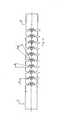
- Fig. 14shows a bendable section 8 showing nine pipe segments and two end sections, namely the nine respectively identically formed intermediate pipe segments 9 and the respective end pipe segments 17 and 18, respectively, and thus having ten hinge points.
- the drawn in this figure angle ⁇ and ⁇ 1 and the distance a from pin to pin of two adjacent pipe segments 9can be chosen smaller and / or larger, thereby changing the flexibility of the bendable portion 8.
- the dimensions of these angles and distancescan be set by the skilled person as desired.
- the above-described embodiment of the bendable portion 8is due to the each offset by 180 ° arranged connecting means 11 and due to the presence of only two, each offset by 90 ° to the connecting means around the circumference arranged control cables only in one plane bendable, but it may also be desirable be that the bendable portion in a second, perpendicular to the first plane Level should be bendable, so that ultimately a spatial movement of the bendable Section becomes possible.
- the tube segments 109 "of the inner bendable Section 108 "show that adjacent to the 180 ° opposite axially extending grooves 123 and 124 for the control cables for moving the bendable Section in a first plane in each case by 90 ° offset two further grooves 123 'and 124' are present for the control cables for bending the bendable section in the second Level are provided.
- FIGS. 11A to 11Dshow the corresponding pipe segments 109 ". composite inner bendable portion 108 " outer bendable section made of those shown in Figs. 9 to 9C Pipe segments 109 'has been omitted.
- the inventionalso provides a method for producing the above-described bendable Sections available, the method is characterized in that first rigid pipes 208 'and 208 ", respectively, as shown in FIGS. 3 and 4 are provided each have the desired outer and inner diameter, depending on whether from it inner bendable section 8 "or an outer bendable section 8 'is to be created Inner bendable section 8 "arise, already has to be provided rigid pipe the axially required grooves 23, 24, 23 ', 24', 123, 124, 123 'required for the control cables and 124 'up.
- Such a rigid tube 208 'or 208"becomes a laser cutting device used, with two alternatives are conceivable, namely that the tube is fixed and the Laser cutting device moves around the pipe and also opposite the pipe in axial direction can be moved, or the laser cutting device in one fixed position is arranged and moved the rigid pipe both in the axial direction as well as can be twisted.
- the laser cutting deviceis programmed so that either the tube relative to the laser beam or the laser beam relative to the Tube is moved or rotated in the axial and radial directions and the laser beam on a section line SL is performed, which represented in the figures and the pipe segments with the connecting means forming sections produces.
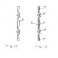
- Fig. 12is such developed cut line SL for the laser guide and
- Fig. 13shows the hatched shown and after performing the laser cut on that shown in Fig. 12 Cut line from the rigid tube cut wall parts WT, either be broken out mechanically or by ultrasound.
Landscapes
- Health & Medical Sciences (AREA)
- Life Sciences & Earth Sciences (AREA)
- Surgery (AREA)
- Engineering & Computer Science (AREA)
- Biomedical Technology (AREA)
- Molecular Biology (AREA)
- Pathology (AREA)
- Radiology & Medical Imaging (AREA)
- Nuclear Medicine, Radiotherapy & Molecular Imaging (AREA)
- Biophysics (AREA)
- Physics & Mathematics (AREA)
- Heart & Thoracic Surgery (AREA)
- Medical Informatics (AREA)
- Optics & Photonics (AREA)
- Animal Behavior & Ethology (AREA)
- General Health & Medical Sciences (AREA)
- Public Health (AREA)
- Veterinary Medicine (AREA)
- Rehabilitation Therapy (AREA)
- Manufacturing & Machinery (AREA)
- Endoscopes (AREA)
- Media Introduction/Drainage Providing Device (AREA)
Abstract
Description
Translated fromGermanDie Erfindung bezieht sich auf- einen biegbaren Abschnitt, der am distalen Ende einesEinführtubus eines Endoskopes angeordnet ist, umfassend eine Mehrzahl von Rohrsegmenten,wobei jedes dieser Rohrsegmente Verbindungsmittel aufweist, die mit den Verbindungsmittelndes benachbarten Rohrsegmentes zusammenwirken, sowie Steuerzüge, mit denen dieAbbiegung des biegbaren Abschnittes steuerbar ist, und auf ein Verfahren zur Herstellung einessolchen biegbaren Abschnittes.The invention relates to a bendable portion which at the distal end of aInsertion tube of an endoscope is arranged, comprising a plurality of tube segments,each of these tube segments having connection means connected to the connection meansthe adjacent pipe segment cooperate, as well as control cables, with which theTurning the bendable section is controllable, and to a method for producing asuch bendable section.
Endoskope mit solchen biegbaren und steuerbaren Abschnitten an den distalen Enden ihresEinführtubus werden in einer großen Anzahl von Druckschriften beschrieben, einige davonsollen nachstehend näher erörtert werden, z. B. die DE 101 43 966 A1, DE 42 34 833 A1, EP 0439 931 B1 und EP 1 090 581 B1.Endoscopes with such bendable and controllable sections at the distal ends of theirInsertion tubes are described in a large number of references, some of themwill be discussed in more detail below, z. For example, DE 101 43 966 A1, DE 42 34 833 A1, EP 0439 931 B1 and EP 1 090 581 B1.
Alle diese genannten Druckschriften zeigen biegbare Abschnitte, die jeweils an den distalenEnden eines Einführtubus eines Endoskopes vorgesehen sind, wobei der Einführtubus starroder flexibel ausgebildet sein kann. Eine wesentliche Eigenschaft des biegbaren Abschnittesdes Einführtubus aber ist, daß dieser hinsichtlich seiner Abbiegungsrichtung steuerbar ist, undzwar über in dem Einführtubus integrierte Steuerzüge.All of these cited references show bendable sections, each at the distalEnds of an insertion tube of an endoscope are provided, wherein the insertion tube rigidor may be flexible. An essential feature of the bendable sectionthe insertion tube is, however, that this is controllable with respect to its direction of turn, andalthough via in the insertion tube integrated control cables.
In der EP 1 090 581 B1 ist ein biegbarer Abschnitt beschrieben, der über zwei Steuerzügeverfügt, d. h., der biegbare Abschnitt ist nur in einer Ebene abbiegbar, wohingegen die übrigenvorgenannten Druckschriften biegbare Abschnitte mit jeweils vier Steuerzügen zeigen, die dasAbbiegen des biegbaren Abschnittes in zwei Ebenen und infolge dessen ein räumlichesAbbiegen erlauben.
Alle diese bekannten biegbaren Abschnitte bestehen aus einer Mehrzahl von Verbindungs-bzw. Gelenkringen, allgemeiner gesagt, aus Rohrsegmenten, die miteinander überVerbindungsmittel gegeneinander verschwenkbar miteinander verbunden sind, wobei dieseVerbindungsmittel jeweils an den Stirnseiten der Rohrsegmente angeordnet sind.All of these known bendable sections consist of a plurality of connecting parts.or joint rings, more generally, of pipe segments, the one above the otherConnecting means are mutually pivotally connected to each other, theseConnecting means are respectively arranged on the end faces of the pipe segments.
Die Anordnung der Verbindungsmittel an den jeweiligen Stirnseiten der einzelnenRohrsegmente ist nun davon abhängig, ob der biegbare Abschnitt nur in einer Ebene abbiegbarsein soll oder ob er räumlich, also in zwei Ebenen abbiegbar sein soll. Soll der biegbareAbschnitt nur, wie in der EP 1 090 581 B1 dargestellt, in einer Ebene abbiegbar sein, dann sindan jeder Stirnseite, also in distaler oder in proximaler Richtung gesehen, jeweils zweiVerbindungsmittel angeordnet, wobei sich diese Verbindungsteile um 180° in Umfangsrichtungversetzt gegenüberliegen. Die Schwenkachsen dieser Verbindungsmittel an den einzelnenRohrsegmenten verlaufen jeweils, in axialer Richtung gesehen, auf einer durchgehendenMantellinie.The arrangement of the connecting means on the respective end faces of the individualPipe segments is now dependent on whether the bendable section can only be bent in one planeshould be or be spatially, so in two levels bendable. Should the bendableSection only, as shown in
Für den Fall, daß der biegbare Abschnitt allerdings räumlich abbiegbar sein soll, müssen dieeinzelnen Rohrsegmente auch in einer zweiten Ebene, die um 90° versetzt zu der ersten Ebeneangeordnet ist, gegeneinander verschwenkbar sein, dazu ist es erforderlich, daß die jeweils anden Stirnseiten eines Rohrsegmentes angeordneten Verbindungsmittel gegeneinander um 90°versetzt angeordnet sind, wie beispielsweise der EP 0 439 931 B1 zu entnehmen ist. Damitdiese räumliche Abbiegung auch gesteuert werden kann, sind selbstverständlich vierSteuerzüge angeordnet, die jeweils 90° zueinander umfangsmäßig versetzt angeordnet sind.In the event that the bendable section but should be spatially bendable, theindividual pipe segments also in a second plane, offset by 90 ° to the first planeis arranged to be pivoted against each other, it is necessary that each ofthe end faces of a pipe segment arranged connecting means against each other by 90 °arranged offset, as for example, EP 0 439 931 B1 can be seen. In order toThis spatial turn can also be controlled, of course, fourControl cables arranged, which are arranged offset by 90 ° to each other circumferentially.
Die Verbindungsmittel sind als über die jeweiligen Stirnseiten der Rohrsegmente vorstehendeLaschen ausgebildet, die beispielsweise Bohrungen aufweisen, in welche radial einstehendeBolzen eingeführt sind. Dies bedeutet, daß diese Verbindungsmittel, speziell dielaschenförmigen Vorsprünge, sich überlappen müssen und deswegen nach außen oder nachinnen aus der Mantelfläche der Rohrsegmente abgebogen sind. Diese Verbindungsmittel wieauch die darin angeordneten Bolzen stehen dann aber über den Außen- und/oder Innenumfangdes biegbaren Abschnittes hervor, insbesondere aber ragen die Bolzen in den Innenraum desbiegbaren Abschnittes hinein.The connecting means are projecting as over the respective end faces of the pipe segmentsLugs formed, for example, have holes in which radially einstehendeBolts are inserted. This means that these connecting means, especially thelug-shaped projections, must overlap and therefore to the outside or toare bent inside of the lateral surface of the pipe segments. These fasteners likebut the bolts arranged therein are then on the outer and / or inner circumferencethe bendable portion out, but in particular the bolts protrude into the interior of thebendable section into it.
Die Steuerzüge werden dabei im Inneren des biegbaren Abschnittes geführt, und zwar, wie inder DE 42 34 833 A1 und der EP 1 090 581 B1 gezeigt, in Führungen, die an den Innenseiteneinzelner Rohrsegmente vorgesehen sind. Bei der DE 101 43 966 A1 wie auch der EP 0 439931 B1 sind solche Führungen unmittelbar an den in den Innenraum des biegbaren Abschnitteseinstehenden Bolzenköpfen der Verbindungsmittel ausgebildet, ähnlich wie Ringösen.The control cables are guided inside the bendable section, as inDE 42 34 833 A1 and
Allen diesen bekannten biegbaren Abschnitten ist gemein, daß sie aus Rohrsegmenten undVerbindungsteilen bestehen, die äußerst aufwendig hinsichtlich ihrer Herstellung, insbesondereaber auch bezüglich ihrer Montage sind und es ist deshalb ein erstes Ziel der hier vorliegendenErfindung, diesen Herstellungs- und Montageprozeß wesentlich zu vereinfachen, sowie denInnenraum des biegbaren Abschnittes glattwandig und frei von Vorsprüngen auszubilden.All these known bendable sections is common that they are made of pipe segments andThere are connecting parts that are extremely expensive in terms of their production, in particularbut also in terms of their assembly and it is therefore a first goal of the present hereInvention to simplify this manufacturing and assembly process significantly, as well as theInterior of the bendable portion smooth-walled and free of projections form.
Es ist aber auch ein weiteres Ziel der Erfindung, den Innenraum frei von Steuerzügenauszubilden, die sonst den Einbau von ebenfalls erforderlichen Leuchtmitteln, beispielsweiseGlasfasersträngen und elektrischen Leitungen für die Optik- und Sensoreinheit am distalenEnde des biegbaren Abschnittes behindern. Insbesondere soll der Innenraum aber auch fürInstallationen freigehalten werden, die für Spül- und Absaugvorgänge und gegebenenfalls amdistalen Ende wirkende operative Werkzeuge benötigt werden.But it is also another object of the invention, the interior of taxpicksform, otherwise the installation of lighting equipment also required, for exampleFiber optic strands and electrical leads for the optics and sensor unit at the distal endHinder the end of the bendable section. In particular, the interior but also forInstallations are kept free for rinsing and suction operations and, if necessary, ondistal end-acting surgical tools are needed.
Ein drittes Ziel der vorliegenden Erfindung ist es, ein Verfahren zur Herstellung eines solchenbiegbaren Abschnittes aus einem vorgegebenen biegesteifen Rohr zu schaffen, der esermöglicht, daß die einzelnen Rohrsegmente mit ihren Verbindungsmitteln gar nicht mehr unterVerwendung weiterer Verbindungsmittel, beispielsweise Bolzen und Nieten etc.,zusammengefügt werden müssen, sondern, sozusagen in einem Verfahrensschritt,gebrauchsfertig und weiterverwendbar sind.A third object of the present invention is to provide a process for producing the samebendable section from a given rigid pipe to create itallows the individual pipe segments with their connecting means no longer underUse of further connecting means, for example bolts and rivets etc.,must be joined together, but, so to speak, in a procedural step,ready to use and reusable.
Das erste Ziel wird bei einem biegbaren Abschnitt der eingangs beschriebenen Art dadurcherreicht, daß die jeweiligen Verbindungsmittel eines Rohrsegmentes an dessen Stirnseiten inaxialer Richtung vorstehend und innerhalb des Mantels des Rohrsegmentes liegendausgebildet sind und die Dicke des Mantels nicht überschreiten, wobei die Verbindungsmittel,die an den jeweiligen Stirnseiten benachbarter Rohrsegmente vorgesehen sind und sichgegenüberliegen, sich nach Art einer scharnierförmigen Verbindung ergänzen.
Diese erfindungsgemäßen Verbindungsmittel stehen weder nach außen noch nach innen überdie äußere bzw. innere Mantelfläche der Rohrsegmente hervor und es sind auch keinezusätzlichen Mittel vorgesehen, die die Verbindungsmittel aneinanderhalten und dadurchVorsprünge bilden. Es kann also auf bolzen- und/oder nietenförmige Mittel, die radialausgerichtete Schwenkachsen bilden und die jeweiligen Verbindungsmittel miteinanderschwenkbar verbinden, verzichtet werden. Die Verbindungsmittel sind vielmehr innerhalb derManteldicke der Rohrsegmente ausgebildet und stehen in axialer Richtung ineinander ein undsind gegeneinander verschwenkbar. Durch diese erfindungsgemäße Ausbildung wird dafürSorge getragen, daß sowohl die äußere als auch die innere Mantelfläche der Rohrsegmenteund damit insbesondere der Innenraum des biegbaren Abschnittes keinerlei Vorsprüngeaufweist, es entstehen glattflächige Außen- und Innenseiten.The first object is achieved in a bendable portion of the type described above, characterized in that the respective connecting means of a pipe segment are formed on the end sides in the axial direction above and within the shell of the pipe segment lying and not exceed the thickness of the shell, wherein the connecting means, the are provided on the respective end faces of adjacent pipe segments and facing each other, complement each other in the manner of a hinge-shaped connection.
These connecting means according to the invention are neither outwardly nor inwardly beyond the outer and inner circumferential surface of the pipe segments and there are also no additional means provided which hold the connecting means together and thereby form projections. It can therefore be omitted on bolt and / or rivet-shaped means forming radially aligned pivot axes and the respective connecting means pivotally connected to each other. The connecting means are rather formed within the shell thickness of the pipe segments and are in the axial direction into one another and are mutually pivotable. By this embodiment of the invention care is taken that both the outer and the inner circumferential surface of the pipe segments and thus in particular the interior of the bendable portion has no projections, there are smooth-surfaced outer and inner sides.
In erfindungsgemäßer Weiterbildung sind die an der einen Stirnseite eines Rohrsegmentesausgebildeten Verbindungsmittel nach Art eines zur Stirnseite eines benachbartenRohrsegmentes gerichtete und vorstehende Zapfen ausgebildet, und sind die an der anderenStirnseite des Rohrsegmentes angeordneten Verbindungsmittel als den Zapfen einesbenachbarten Rohrsegmentes umgreifende Klauen ausgebildet, wobei sowohl der Zapfen alsauch die Klauen Teile des Mantels des jeweiligen Rohrsegmentes sind.
Diese vorbeschriebene Ausbildung der Verbindungsteile erlaubt es, eine die Rohrsegmenteaneinander, haltende und gleichzeitig verschwenkbare Verbindung herzustellen, ohne daßzusätzliche Mittel in Form von Bolzen o. ä. eingesetzt werden müssen. Die klauenförmigenVerbindungsmittel bilden sozusagen eine Klammer zu dem zapfenförmigen Verbindungsmitteldes anderen Rohrsegmentes, so daß ein die Rohrsegmente aneinander haltende Verbindungzustande kommt, ohne daß ein zusätzliches, separates Teil als Verbindungsmittel eingesetztwerden muß.In accordance with the invention, the connecting means formed on the one end face of a pipe segment are designed in the manner of a pin projecting towards the end face of an adjacent pipe segment, and the connecting means arranged on the other end face of the pipe segment are designed as claws encompassing the pin of an adjacent pipe segment, both the pin and the claws are parts of the shell of the respective pipe segment.
This above-described design of the connecting parts makes it possible to produce a tube segments together, holding and simultaneously pivotable connection without additional means in the form of bolts o. Ä. Must be used. The claw-shaped connecting means form, so to speak, a clamp to the pin-shaped connecting means of the other pipe segment, so that a pipe segments holding together connection is made without an additional, separate part must be used as a connecting means.
Vorteilhaft sind die jeweils an einer der Stirnseiten eines Rohrsegmentes angeordnetenVerbindungsmittel entweder als Zapfen oder als Klauen ausgebildet, wobei dann die an deranderen Stirnseite desselben Rohrsegmentes vorgesehenen Verbindungsmittel umgekehrtentweder als Klauen oder als Zapfen ausgebildet sind.
Nach dieser Ausbildung sind die jeweils an einer bestimmten Stirnseite eines Rohrsegmentesvorgesehen Verbindungsmittel, die sich ja um 180° in Umfangsrichtung versetztgegenüberliegen, identisch ausgebildet, entsprechend dann auch die dazu korrespondierendenzapfen- oder klauenförmigen Verbindungsmittel an der einer solchen Stirnseite einesRohrsegmentes gegenüberliegenden Stirnseite eines anderen Rohrsegmentes. Diese jeweilsidentische Ausbildung der Verbindungsmittel an ein und derselben Stirnseite einesRohrsegmentes vereinfacht die Herstellung solcher Rohrsegmente.Advantageously, the respectively arranged on one of the end faces of a pipe segment connecting means are designed either as a pin or as claws, in which case provided on the other end side of the same pipe segment connecting means are formed conversely either as claws or pins.
After this training, each provided on a certain end face of a pipe segment connecting means, which are offset by 180 ° so offset in the circumferential direction, identical, then corresponding to the corresponding pin or claw-shaped connection means at the end face of a pipe segment opposite end face of a other pipe segment. This respectively identical design of the connecting means on one and the same end face of a pipe segment simplifies the production of such pipe segments.
In erfindungsgemäßer Weiterbildung ist der an der Stirnseite eines Rohrsegmentesangeordnete Zapfen nach Art einer kreisförmigen Scheibe ausgebildet und schließen die an derStirnseite des benachbarten Rohrsegmentes angeordneten Klauen eine kreisförmigeAusnehmung zwischen sich ein, welche den Abmessungen des kreisscheibenförmigen Zapfensentspricht, und wobei die Klauen den Zapfen in dieser Ausnehmung aufnehmen.
Eine solche Formgebung der Verbindungsmittel gewährleistet, daß diese innerhalb derAbmessungen des Mantels des Rohrsegmentes liegen und gewährleistet insbesondere, daßdie Klauen weder in axialer Richtung noch in radialer Richtung von dem Zapfen abgezogenwerden können.In accordance with the invention, the pin arranged on the end face of a pipe segment is designed in the manner of a circular disk and the jaws arranged on the end face of the adjacent pipe segment enclose therebetween a circular recess which corresponds to the dimensions of the circular disk-shaped pin, and wherein the jaws are the pin pick up in this recess.
Such a shape of the connecting means ensures that they are within the dimensions of the shell of the pipe segment and in particular ensures that the claws can be deducted neither in the axial direction in the radial direction of the pin.
In weiterer vorteilhafter Ausbildung weisen das am proximalen Ende des biegbaren Abschnittesangeordnete erste Rohrsegment und das am distalen Ende des biegbaren Abschnittesangeordnete letzte Rohrsegment jeweils an ihren die Enden des biegbaren Rohrabschnittesbildenden Stirnseiten keine Verbindungsmittel nach Art von Zapfen und/oder Klauen auf.
Diese jeweiligen ersten und letzten Rohrsegmente des biegbaren Abschnittes sind jeweils ihrenentsprechenden Bestimmungen gemäß ausgebildet. So ist das letzte Rohrsegment am distalenEnde des biegbaren Abschnittes zur Aufnahme einer Optik und eines Sensors etc. undinsbesondere zum Eindringen in eine Körperhöhle vorgesehen und unterliegt deshalb einerspeziellen Ausbildung. Ebenso verhält es sich mit dem am proximalen Ende des biegbarenAbschnittes vorgesehenen Rohrsegment, dieses ist in einer besonderen und hier nichtbeschriebenen Form mit dem proximalen Teil des rohrförmigen Einführtubus des Endoskopesverbunden.In a further advantageous embodiment, the first tube segment arranged at the proximal end of the bendable section and the last tube segment arranged at the distal end of the bendable section have no connection means in the manner of pins and / or claws at their end faces forming the ends of the bendable tube section.
These respective first and last pipe segments of the bendable section are respectively formed according to their respective provisions. Thus, the last tube segment is provided at the distal end of the bendable portion for receiving an optic and a sensor, etc. and in particular for penetrating into a body cavity and is therefore subject to a special training. The same applies to the tube segment provided at the proximal end of the bendable section, which in a special and not described form is connected to the proximal part of the tubular insertion tube of the endoscope.
Zur Erreichung des zweiten Zieles der Erfindung ist in dem biegbaren Abschnitt, im folgendenstets äußerer biegbarer Abschnitt genannt, ein hinsichtlich der Anzahl der Rohrsegmente undder Anordnung der Verbindungsteile an diesen Rohrsegmenten identisch ausgebildeter zweiter,innerer biegbarer Abschnitt eingesetzt, dessen Außendurchmesser dem Innendurchmesser desäußeren biegbaren Abschnittes so angepaßt ist, daß der innere biegbare Abschnitt in denäußeren biegbaren Abschnitt einschiebbar ist, wobei der innere biegbare Abschnitt in seineräußeren Umfangsfläche mindestens zwei um 180° in Umfangsrichtung gegeneinander versetztangeordnete und über die einzelnen Rohrsegmente in axialer Richtung verlaufende Nutenaufweist, in welchen jeweils ein Steuerzug geführt ist, wobei die beiden Nuten jeweils inUmfangsrichtung um 90° versetzt gegenüber den Verbindungsmitteln angeordnet sind.
Durch die besondere Ausbildung des biegbaren Abschnittes in einer sozusagendoppelwandigen Form, ergibt sich unter Ausbildung der Nuten in der äußeren Umfangsflächedes inneren biegbaren Abschnittes eine sichere Führung für die Steuerzüge, gleichzeitig wirderreicht, daß der Innenraum des doppelwandigen biegbaren Abschnittes, insbesondere also derInnenraum des inneren biegbaren Abschnittes frei bleibt von Seilzügen, wodurch das Einführenvon sonstigen Schläuchen, elektrischen Leitungen, etc. sehr vereinfacht wird. Auch ist derEinbau der Seilzüge im doppelwandigen biegbaren Abschnitt verhältnismäßig einfach, müssendie Seilzüge doch nicht durch ösenförmige Führungen hindurchgeführt bzw. in diese eingefädeltwerden, vielmehr können die Seilzüge beim Einschieben des inneren biegbaren Abschnittes inden äußeren biegbaren Abschnitt bereits in die jeweiligen Nuten eingelegt und in einemArbeitsgang eingebaut, andererseits aber auch erst nach dem Zusammenbau des äußeren undinneren biegbaren Abschnittes in die Nuten eingeschoben werden.To achieve the second object of the invention is in the bendable portion, hereinafter called always outer bendable portion, one with respect to the number of pipe segments and the arrangement of the connecting parts of these pipe segments identically formed second, inner bendable section used, the outer diameter of the inner diameter of the outer bendable portion is adapted so that the inner bendable portion in the outer bendable portion is inserted, wherein the inner bendable portion has in its outer peripheral surface at least two 180 ° circumferentially offset from each other and extending over the individual pipe segments in the axial direction grooves, in each of which a control cable is guided, wherein the two grooves are each offset in the circumferential direction by 90 ° relative to the connecting means.
Due to the special design of the bendable portion in a so-called double-walled shape, results in the formation of grooves in the outer peripheral surface of the inner bendable portion a secure guide for the control cables, while ensuring that the interior of the double-walled bendable section, ie in particular the interior the inner bendable portion remains free of cables, whereby the insertion of other hoses, electrical cables, etc. is greatly simplified. Also, the installation of the cables in the double-walled bendable section is relatively simple, the cables must not be passed through eye-shaped guides or threaded into this, but the cables can be inserted into the respective grooves when inserting the inner bendable portion in the outer bendable portion and incorporated in one operation, on the other hand, but only after the assembly of the outer and inner bendable portion are inserted into the grooves.
Dadurch, daß die äußere Umfangsfläche des inneren biegbaren Abschnittes dicht an derinneren Umfangsfläche des äußeren biegbaren Abschnittes anliegt, bilden die Nuten mit der inneren Umfangsfläche des äußeren biegbaren Abschnittes eine geschlossene kanalförmigeFührung, in der die Seilzüge ohne Klemmungen gleiten können.Characterized in that the outer peripheral surface of the inner bendable portion close to theinner circumferential surface of the outer bendable portion rests, forming the grooves with theinner peripheral surface of the outer bendable portion a closed channel-shapedGuide in which the cables can slide without clamping.
In einer speziellen Ausbildung sind an der äußeren Umfangsfläche des inneren biegbarenAbschnittes vier axial verlaufende Nuten vorgesehen, die jeweils um 90° in Umfangsrichtungzueinander versetzt angeordnet sind, wobei gleichzeitig die an den jeweiligen Stirnseiten derRohrsegmente paarweise angeordneten Verbindungsteile jeweils um 90° zueinander versetztsind.
Die Anordnung von vier Seilzügen ist erforderlich, wenn der biegbare Abschnitt in zwei Ebenen,also räumlich biegbar sein soll, gleichzeitig müssen dann aber auch die Verbindungsmitteljeweils alternierend, in Umfangsrichtung um 90° versetzt zueinander an den jeweiligenRohrsegmenten angeordnet sein, damit ein räumliches Abbiegen des biegbaren Abschnittesermöglicht werden kann.In a specific embodiment, four axially extending grooves are provided on the outer peripheral surface of the inner bendable portion, which are each offset by 90 ° in the circumferential direction to each other, at the same time the paired at the respective end faces of the pipe segments connecting parts are offset by 90 ° to each other ,
The arrangement of four cables is required if the bendable portion in two planes, so it should be spatially bendable, but then also the connecting means must each be arranged alternately, offset in the circumferential direction by 90 ° to each other at the respective pipe segments, thus a spatial turn the bendable section can be made possible.
Damit die ineinandergesetzten inneren und äußeren biegbaren Abschnitte sich nicht etwagegeneinander verschieben, wodurch die Biegbarkeit bzw. Verschwenkbarkeit der jeweiligenRohrsegmente gegeneinander ver-, zumindest aber behindert werden könnte, sind dieeinzelnen Rohrsegmente der inneren und der äußeren Abschnitte, wenn sie sich exaktgegenüberliegen, also eine vollständige Kongruenz der biegbaren Abschnitte hergestellt ist,jeweils durch eine Punktschweißung aneinander fixiert.
Eine solche Punktschweißung ist einfach durchzuführen und garantiert die Unverschiebbarkeitder jeweiligen biegbaren Abschnitte zueinander.Thus, the nested inner and outer bendable sections do not move against each other, whereby the flexibility or pivotability of the respective pipe segments against each other ver, but could be hindered at least, the individual pipe segments of the inner and outer sections, if they are exactly opposite, So a complete congruence of the bendable sections is made, each fixed by a spot weld together.
Such a spot weld is easy to perform and guarantees the immobility of the respective bendable sections to each other.
Zur Erreichung des vorstehend beschriebenen dritten Zieles wird ein Verfahren zur Herstellungeines biegbaren Abschnittes, der eine Vielzahl von Rohrsegmenten aufweist, welche in einerReihe angeordnet sind und miteinander über Verbindungsteile gegeneinander schwenkbarmiteinander verbunden sind, bereitgestellt, wobei das Verfahren folgende Schritte umfaßt:
In einer vorteilhaften Ausbildung des vorbeschriebenen Verfahrens wird das biegesteife Rohr inder Schneidevorrichtung unter dem ortsfesten Laserstrahl gedreht und/oder axial verschoben.
Diese Form der Durchführung des Verfahrens erlaubt eine einfachere Konstruktion derLaserschneidevorrichtung.In an advantageous embodiment of the method described above, the rigid pipe is rotated in the cutting device under the stationary laser beam and / or moved axially.
This form of implementation of the method allows a simpler design of the laser cutting device.
Schließlich können in weiterer vorteilhafter Weise die aus dem Rohr herausgeschnittenenWandteile mittels Ultraschall aus diesem herausgebrochen werden.
Dieses Verfahren weist den Vorteil auf, daß keine mechanisch wirkenden Werkzeugeeingesetzt werden müssen.Finally, in a further advantageous manner, the cut out of the tube wall parts can be broken out of this by means of ultrasound.
This method has the advantage that no mechanically acting tools must be used.
Eine die Erfindung nicht beschränkende und diese nur beispielhaft beschreibendeAusführungsform wird anhand der nachstehend genannten Figuren erläutert.A non-limiting the invention and this only by way of example descriptiveEmbodiment will be explained with reference to the figures below.
- Fig. 1:Fig. 1:
- eine Seitenansicht auf ein Endoskop, speziell ein Nasopharyngoskopa side view of an endoscope, especially a nasopharyngoscope
- Fig. 1A:Fig. 1A:
- eine etwas vergrößerte Ansicht des distalen Endes eines Einführtubus,a slightly enlarged view of the distal end of an insertion tube,
- Fig. 1B:1B:
- eine Ansicht auf das distale Ende gemäß Fig. 1A in einer um ca. 125° abgebogenenStellung,a view of the distal end of FIG. 1A in a bent by about 125 °Position,
- Fig. 2A:Fig. 2A:
- eine nochmals vergrößerte Ansicht auf das distale Ende gemäß Fig. 1A, versehen miteiner teilweise aufgebrochenen schlauchförmigen Kunststoffumhüllung,a further enlarged view of the distal end of FIG. 1A, provided witha partially broken tubular plastic wrap,
- Fig. 2B:Fig. 2B:
- eine Ansicht auf das distale Ende gemäß Fig. 2A, jedoch in einer abgebogenenStellung,a view of the distal end of FIG. 2A, but in a bentPosition,
- Fig. 3:3:
- eine Ansicht auf ein biegesteifes Rohr vor der Ausbildung zu einem äußerenbiegbaren Abschnitt des Einführtubus,a view of a rigid tube before training to an outerbendable section of the insertion tube,
- Fig. 4:4:
- eine Ansicht auf ein biegesteifes Rohr vor der Ausbildung zu einem inneren biegbarenAbschnitt des Einführtubus,a view of a rigid tube before training to an inner bendableSection of the insertion tube,
- Fig. 5A:Fig. 5A:
- eine Draufsicht auf den äußeren biegbaren Abschnitt,a plan view of the outer bendable section,
- Fig. 5B:Fig. 5B:
- einen Längsschnitt gemäß Linie B-B in Fig. 5A,a longitudinal section along line B-B in Fig. 5A,
- Fig. 5C:Fig. 5C:
- eine Stirnansicht auf den äußeren biegbaren Abschnitt,an end view of the outer bendable section,
- Fig. 5D:Fig. 5D:
- eine perspektivische Seitenansicht des äußeren biegbaren Abschnitts gemäß Fig. 5A,a perspective side view of the outer bendable portion of FIG. 5A,
- Fig. 6A:6A:
- eine Draufsicht auf den inneren biegbaren Abschnitt des Einführtubus,a plan view of the inner bendable portion of the insertion tube,
- Fig. 6B:Fig. 6B:
- einen Schnitt durch den inneren biegbaren Abschnitt gemäß Linie B-B in Fig. 6A,a section through the inner bendable portion along the line B-B in Fig. 6A,
- Fig. 6C:Fig. 6C:
- eine Stirnansicht auf den inneren biegbaren Abschnitt,an end view of the inner bendable section,
- Fig. 6D:Fig. 6D:
- eine perspektivische Seitenansicht des inneren biegbaren Abschnitts gemäß Fig. 6A,3 a perspective side view of the inner bendable section according to FIG. 6A,
- Fig. 7A:Fig. 7A:
- eine Draufsicht auf das biegbare distale Ende des Einführtubus, bestehend ausäußerem und innerem biegbaren Abschnitt,a plan view of the bendable distal end of the insertion tube, consisting ofouter and inner bendable section,
- Fig. 7B:Fig. 7B:
- einen Schnitt gemäß Linie B-B durch das biegbare distale Ende gemäß Fig. 7A,a section along line B-B through the bendable distal end of FIG. 7A,
- Fig. 7C:Fig. 7C:
- eine Stirnansicht auf das biegbare distale Ende mit äußerem und innerem biegbarenAbschnitt,an end view of the bendable distal end with outer and inner bendableSection,
- Fig. 7D:Fig. 7D:
- eine perspektivische Seitenansicht auf das biegbare distale Ende gemäß Fig. 7A,a perspective side view of the bendable distal end of FIG. 7A,
- Fig. 8:Fig. 8:
- eine perspektivische Darstellung auf ein einzelnes Rohrsegment des äußerenbiegbaren Abschnitts,a perspective view of a single pipe segment of the outerbendable section,
- Fig. 8A:8A:
- eine Draufsicht auf das Rohrsegment gemäß Fig. 8,a top view of the pipe segment of FIG. 8,
- Fig. 8B:Fig. 8B:
- einen Schnitt gemäß Linie B-B in Fig. 8A durch das Rohrsegment,a section along line B-B in Fig. 8A through the pipe segment,
- Fig. 8C:8C:
- eine Stirnansicht auf das Rohrsegment,an end view of the pipe segment,
- Fig. 8D:Fig. 8D:
- eine vergrößerte Darstellung des Details D gemäß Fig. 8B,an enlarged view of the detail D of FIG. 8B,
- Fig. 9:Fig. 9:
- eine perspektivische Seitenansicht auf ein Rohrsegment des äußeren Abschnitts, beidem die Verbindungsmittel an einer ersten Stirnseite um 90° zu denVerbindungsmitteln an der anderen Stirnseite versetzt angeordnet sind,a side perspective view of a pipe segment of the outer portion, atthe connecting means at a first end face at 90 ° to theConnecting means are arranged offset at the other end,
- Fig. 9A:Fig. 9A:
- eine Draufsicht auf das Rohrsegment gemäß Fig. 9,a top view of the pipe segment of FIG. 9,
- Fig. 9B:Fig. 9B:
- einen Schnitt gemäß Linie B-B in Fig. 9A durch das Rohrsegment,a section along line B-B in Fig. 9A through the pipe segment,
- Fig. 9C:Fig. 9C:
- eine Stirnansicht des Rohrsegmentes,an end view of the pipe segment,
- Fig. 9D:Fig. 9D:
- eine vergrößerte Darstellung des Details D in Fig. 9Ban enlarged view of the detail D in Fig. 9B
- Fig. 10:Fig. 10:
- eine perspektivische Seitenansicht auf ein Rohrsegment des inneren biegbarenAbschnitts mit entsprechender Anordnung der zueinander versetztenVerbindungsmittel gemäß Fig. 9,a side perspective view of a pipe segment of the inner bendableSection with appropriate arrangement of staggeredConnecting means according to FIG. 9,
- Fig. 10A:10A:
- eine Draufsicht auf das Rohrsegment gemäß Fig. 10,a top view of the pipe segment of FIG. 10,
- Fig. 10B:Fig. 10B:
- einen Schnitt durch das Rohrsegment gemäß Linie B-B in Fig. 10A,a section through the pipe segment along the line B-B in Fig. 10A,
- Fig. 10C:Fig. 10C:
- eine Stirnansicht auf das Rohrsegment,an end view of the pipe segment,
- Fig. 10D:Fig. 10D:
- eine Ansicht der gegenüberliegenden Stirnseite des Rohrsegmentes,a view of the opposite end side of the pipe segment,
- Fig. 11A:Fig. 11A:
- eine Draufsicht auf einen inneren biegbaren Abschnitt für 4-fach Seilzüge,a top view of an inner bendable section for quadruple cables,
- Fig. 11B:Fig. 11B:
- einen Schnitt durch den inneren biegbaren Abschnitt gemäß Linie B-B in Fig. 11A,a section through the inner bendable portion along the line B-B in Fig. 11A,
- Fig. 11C:Fig. 11C:
- eine Stirnansicht auf den inneren biegbaren Abschnitt,an end view of the inner bendable section,
- Fig. 11D:Fig. 11D:
- eine perspektivische Seitenansicht auf den inneren biegbaren Abschnitt für 4-fachSeilzüge,a side perspective view of the inner bendable section for 4-foldCables,
- Fig. 12:Fig. 12:
- Darstellung der Laserschnittlinie in abgewickelter Form,Representation of the laser cutting line in unwound form,
- Fig. 13:Fig. 13:
- Darstellung der aus dem Rohr herauszubrechenden freigeschnittenen Wandteile undRepresentation of the cut out of the tube cut wall parts and
- Fig. 14:Fig. 14:
- Darstellung eines biegbaren Abschnitts mit Abstands -und Winkelangaben.Representation of a bendable section with distance and angle information.
Das in Fig. 1 dargestellte Endoskop 1 besteht im wesentlichen aus einem zur Handhabung undBetätigung bestimmten proximalen Abschnitt 2, der ein Okular 3 und ein Handbetätigungsteil 4aufweist, und weiterhin aus einem zum Einführen in eine Körperhöhle vorgesehenen distalenAbschnitt 5, der als Einführtubus 6 ausgebildet ist und welcher an seinem distalen Ende 7 einenbiegbaren Abschnitt 8 aufweist. Dieser biegbare Abschnitt 8 unterscheidet sich von einembeispielsweise flexibel ausgebildeten Einführtubus 6 dadurch, daß er steuerbar abbiegbar ist,also vom Handbedienungsteil 4 aus in gewünschte Richtungen abgebogen werden kann, wie inFiguren 1A und 1B dargestellt. Kann der Einführtubus 6 in einfacher Weise alsKunststoffschlauch ausgebildet sein, so ist dies bei dem steuerbaren biegbaren Abschnitt nichtmöglich, der biegbare Abschnitt muß, wie den Figuren 2A und 2B zu entnehmen ist, auseinzelnen, sich gegeneinander verstellbaren Rohrsegmenten 9 hergestellt sein, die überSteuerzüge 10 in die gewünschte Richtung verstellbar sind, wobei die Rohrsegmente 9 überVerbindungsmittel 11 miteinander verschwenkbar verbunden sind.The illustrated in Fig. 1
Gegenüber den eingangs beschriebenen bekannten biegbaren Abschnitten von Endoskopensind die in diesem Ausführungsbeispiel beschriebenen Rohrsegmente 9 doppelwandigausgebildet, d. h., sie bestehen aus einem äußeren und einem inneren, jeweils zueinanderidentisch ausgebildeten Rohrsegment 9' bzw. 9", die lediglich unterschiedliche Durchmesserund gegebenenfalls auch unterschiedliche Wanddicken aufweisen und in einfacher Weiseineinander geschoben werden.Compared to the known bendable sections of endoscopes described abovethe
Da diese äußeren und inneren Rohrsegmente 9' bzw. 9" im wesentlichen hinsichtlich ihrerKonfiguration identisch ausgebildet sind, wird im weiteren zunächst die Ausbildung einessolchen Rohrsegmentes am Beispiel eines äußeren Rohrsegmentes 9', also am Beispiel einesaus solchen Rohrsegmenten 9' gebildeten äußeren biegbaren Abschnittes 8' des Einführtubusdes Endoskopes 1 beschrieben.Since these outer and
Wie den Figuren 5A bis 5D und den Figuren 8 bis 8D zu entnehmen ist, weisen die einzelnenRohrsegmente 9' an ihren jeweiligen Stirnseiten 12 bzw. 13 in axialer Richtung vorstehendeVerbindungsmittel 11 auf, wobei diese Verbindungsmittel 11 zwei unterschiedlicheAusführungsformen aufweisen. So ist das an der Stirnseite 12 eines Rohrsegmentes 9' vorstehende Verbindungsmittel 11 als Zapfen 14 ausgebildet, der nach Art einer kreisförmigenScheibe aus dem Mantel 15' des Rohrsegmentes 9' herausgeschnitten ist.As can be seen in FIGS. 5A to 5D and FIGS. 8 to 8D, the individual elements are shownPipe segments 9 'at their respective end faces 12 and 13 in the axial direction projecting
Das an der gegenüberliegenden Stirnseite 13 vorgesehene Verbindungsmittel 11 ist dagegenals den Zapfen 14 umgreifende Klauen 16 ausgebildet, die paarweise an der Stirnseite 13vorgesehen sind. Diese Klauen 16 bilden zwischen sich eine kreisförmige Ausnehmung aus, diedie Abmessungen des kreisscheibenförmigen Zapfens 14 aufweisen. Auch diese Klauen 16sind aus dem Mantel 15' des Rohrsegmentes 9' herausgeschnitten. Dies bedeutet, daß dieVerbindungsmittel 11, seien sie als Klauen 16 oder als Zapfen 14 ausgebildet, innerhalb desAußen- bzw. Innenumfanges des biegbaren Abschnittes 8' liegen, also weder nach innen nochnach außen hervorstehen und damit die Dicke des Mantels 15' eines Rohrsegmentes 9' bzw.des biegbaren Abschnittes 8' nicht überschreiten. Dies hat zur Folge, daß sowohl dieInnenwandung als auch die Außenwandung des biegbaren Abschnittes glattflächig ausgebildetist.The provided on the opposite end face 13 connecting
Lediglich die proximalen bzw. distalen Endabschnitte 17' bzw.18' des biegbaren Abschnittes 8'weisen nur an den jeweiligen, den Rohrsegmenten zugewandten Stirnseiten entsprechendausgebildete Verbindungsmittel auf. Die die eigentlichen Enden 19' bzw. 20' bildendenStirnseiten 21' bzw. 22' weisen keine Verbindungsmittel nach Art von Zapfen und/oder Klauenauf.Only the proximal or distal end portions 17 'and 18' of the bendable portion 8 'have only at the respective, the pipe segments facing end faces accordinglytrained connecting means. The actual ends 19 'and 20' formingEnd faces 21 'and 22' have no connection means in the manner of pins and / or clawson.
In den Figuren 6A bis 6B ist der in den äußeren biegbaren Abschnitt 8' gemäß Figuren 5A bis5D einzuschiebende innere biegbare Abschnitt 8" entsprechend dargestellt, dieserunterscheidet sich hinsichtlich der Ausbildung seiner Rohrsegmente 9" und Verbindungsmittel11 nicht gegenüber dem äußeren biegbaren Abschnitt 8', er weist lediglich einen geringerenAußendurchmesser auf, der nahezu dem Innendurchmesser des äußeren biegbarenAbschnittes 8' entspricht, wodurch gewährleistet wird, daß der innere biegbare Abschnitt 8" inden äußeren biegbaren Abschnitt 8' hineingeschoben werden kann.In FIGS. 6A to 6B, the outer bendable section 8 'according to FIGS5D to be inserted inner
Allerdings weist der innere biegbare Abschnitt 8" in seiner äußeren Umfangsfläche mindestenszwei um 180° in Umfangsrichtung gegeneinander versetzt angeordnete und über die einzelnenRohrsegmente 9" in axialer Richtung verlaufende Nuten 23 bzw. 24 auf, in welchen die hiernicht dargestellten Steuerzüge 10 verlaufen.However, the inner
Die Figuren 7A bis 7D zeigen den biegbaren Abschnitt 8, bestehend aus dem äußerenbiegbaren Abschnitt 8' und dem darin eingesetzten inneren biegbaren Abschnitt 8".Insbesondere der Fig. 7B ist zu entnehmen, daß die Gesamtlänge des biegbaren innerenAbschnittes 8" etwas kürzer ist als die Gesamtlänge des äußeren biegbaren Abschnittes 8', dies liegt daran, daß die proximalen bzw. distalen Endabschnitte 17" bzw. 18" kürzerausgebildet sind als die entsprechenden Endabschnitte 17' bzw. 18' des äußeren biegbarenAbschnitts 8'. Dieser Unterschied hängt lediglich von rein konstruktiven Bedingungen ab, die mitden unterschiedlichen Funktionen der Endabschnitte im Zusammenhang stehen und hier keineRolle spielen.Figs. 7A to 7D show the
In den Figuren 8A bis 8D ist ein einzelnes Rohrsegment 9' des äußeren biegbaren Abschnittes8' gezeigt, dem die besondere Ausbildung der zapfen- bzw. klauenförmigen Verbindungsmittel14 bzw. 16 zu entnehmen ist. Um die Rohrsegmente 9' möglichst eng hintereinander anordnenzu können, also ohne besonders große Abstände zwischen ihnen vorsehen zu müssen, sind imMantel 15' des Rohrsegmentes 9' Ausnehmungen 25 vorgesehen, in welche die als Klauen 16ausgebildeten Verbindungsmittel 11 des gegenüberliegenden Rohrsegmentes 9' einstehen.In Figs. 8A to 8D, a single tube segment 9 'of the outer bendable section is shown8 ', the special design of the pin or claw-shaped connection means14 and 16 can be seen. To arrange the tube segments 9 'as closely as possible one behind the otherto be able to provide, so without having to provide particularly large distances between them, are inShell 15 'of the tube segment 9'
Fig. 14 zeigt einen biegbaren Abschnitt 8, der neun Rohrsegmente und zwei Endabschnittezeigt, nämlich die neun jeweils identisch ausgebildeten Zwischen-Rohrsegmente 9 und diejeweiligen End-Rohrsegmente 17 bzw. 18, und folglich zehn Gelenkstellen aufweist. Die indieser Figur eingezeichneten Winkel β und β1 sowie der Abstand a von Zapfen zu Zapfenzweier benachbarter Rohrsegmente 9 können jeweils kleiner und/oder größer gewählt werden,wodurch sich die Biegbarkeit des biegbaren Abschnittes 8 ändert. Die Abmessungen dieserWinkel und Abstände können vom Fachmann je nach Wunsch festgesetzt werden.Fig. 14 shows a
Die vorstehend beschriebene Ausführungsform des biegbaren Abschnittes 8 ist aufgrund derjeweils um 180° versetzt angeordneten Verbindungsmittel 11 und aufgrund des Vorhandenseinsvon nur zwei, jeweils um 90° zu den Verbindungsmitteln über den Umfang versetztangeordneten Steuerzügen nur in einer Ebene abbiegbar, es kann aber auch wünschenswertsein, daß der biegbare Abschnitt in einer zweiten, senkrecht auf der ersten Ebene stehendenEbene abbiegbar sein soll, so daß letztlich eine räumliche Bewegung des biegbarenAbschnittes möglich wird.The above-described embodiment of the
Dazu ist ein Ausführungsbeispiel anhand entsprechend ausgebildeter Rohrsegmente deräußeren und der inneren biegbaren Abschnitte in den Figuren 9 bis 10D dargestellt.For this purpose, an embodiment using appropriately trained pipe segments ofouter and inner bendable sections shown in Figures 9 to 10D.
Bei diesen Rohrsegmenten 109' bzw. 109" liegen sich die an den jeweiligen Stirnseiten 112'bzw. 113' ausgebildeten Zapfen 114' bzw. Klauen 116' nicht genau gegenüber, sondern sindüber den Umfang des Rohrsegmentes jeweils um 90° versetzt. Durch diese, von Rohrsegmentzu Rohrsegment jeweils versetzt angeordneten Verbindungsmittel 111' kann sich nur jedeszweite Rohrsegment in einer ersten Ebene verstellen, die dazwischen liegenden anderenRohrsegmente können sich jeweils in der zweiten Ebene verstellen. Im übrigen ist nur zu sagen, daß die Verbindungsmittel 111', also die Zapfen 114' und die Klauen 116' identisch wiebei der vorbeschriebenen ersten Ausführungsform ausgebildet sind.In these
In den Figuren Fig. 10 bis Fig. 10B sind die Rohrsegmente 109" des inneren biegbarenAbschnitts 108" abgebildet, diese zeigen, daß neben den sich um 180° gegenüberliegendenaxial verlaufenden Nuten 123 bzw. 124 für die Steuerzüge zur Bewegung des biegbarenAbschnittes in einer ersten Ebene jeweils um 90° versetzt zwei weitere Nuten 123' und 124'vorhanden sind, die für die Steuerzüge zur Abbiegung des biegbaren Abschnittes in der zweitenEbene vorgesehen sind.In FIGS. 10 to 10B, the
Die Figuren 11A bis 11D zeigen den aus entsprechenden Rohrsegmenten 109"zusammengesetzten inneren biegbaren Abschnitt 108". Auf eine Abbildung des dazugehörigenäußeren biegbaren Abschnittes, hergestellt aus den in den Figuren 9 bis 9C gezeigtenRohrsegmenten 109' wurde verzichtet.FIGS. 11A to 11D show the
Diese vorbeschriebene erfindungsgemäße Ausbildung eines biegbaren Abschnittes am distalenEnde eines Einführtubus eines Endoskopes gewährleistet gegenüber den bisher bekanntenbiegbaren Abschnitten solcher Endoskope eine glattwandige Ausbildung ohne vorstehendeTeile und ohne Verwendung einzelner Drehzapfen, des weiteren gewährleistet die Ausbildungdes biegbaren Abschnittes mit einem äußeren und einem inneren biegbaren Abschnitt einebesonders einfache Montage der Steuerzüge und gewährleistet darüber hinaus auch, daß derInnenraum des biegbaren Abschnittes glattwandig ist und daher dem Einbau erforderlicherzusätzlicher Bauteile keine Schwierigkeiten bereitet.This above-described inventive design of a bendable portion at the distalEnd of an insertion tube of an endoscope guaranteed over the previously knownbendable sections of such endoscopes a smooth-walled training without protrudingParts and without the use of individual trunnions, further ensures the trainingthe bendable portion having an outer and an inner bendable portion aparticularly simple assembly of the control cables and also ensures that theInterior of the bendable portion is smooth-walled and therefore the installation requiredadditional components no difficulties.
Die Erfindung stellt auch ein Verfahren zur Herstellung der vorbeschriebenen biegbarenAbschnitte zur Verfügung, wobei sich das Verfahren dadurch auszeichnet, daß zunächstbiegesteife Rohre 208' bzw. 208", wie in den Fig. 3 und 4 dargestellt, bereitgestellt werden, diejeweils die gewünschten Außen- und Innendurchmesser aufweisen, je nach dem, ob daraus eininnerer biegbarer Abschnitt 8" öder ein äußerer biegbarer Abschnitt 8' entstehen soll. Soll eininnerer biegbarer Abschnitt 8" entstehen, weist das bereitzustellende biegesteife Rohr bereitsdie für die Steuerzüge erforderlichen axial verlaufenden Nuten 23, 24, 23', 24', 123, 124, 123'und 124' auf.The invention also provides a method for producing the above-described bendableSections available, the method is characterized in that first
Ein solches biegesteifes Rohr 208' bzw. 208" wird in eine Laser-Schneidevorrichtungeingesetzt, wobei zwei Alternativen denkbar sind, nämlich daß das Rohr fixiert ist und dieLaser-Schneidevorrichtung sich um das Rohr herumbewegt und auch gegenüber dem Rohr inaxialer Richtung verschoben werden kann, oder aber die Laser-Schneidevorrichtung in einerfesten Stellung angeordnet ist und das biegesteife Rohr sowohl in axialer Richtung verschoben als auch verdreht werden kann. Die Laser-Schneidevorrichtung wird dermaßen programmiert,daß entweder das Rohr gegenüber dem Laserstrahl oder aber der Laserstrahl gegenüber demRohr in axialer und radialer Richtung verschoben bzw. gedreht wird und der Laserstrahl aufeiner Schnittlinie SL geführt wird, die die in den Figuren dargestellten und die Rohrsegmentemit den Verbindungsmitteln bildenden Abschnitte hervorbringt. In Fig. 12 ist eine solcheabgewickelte Schnittlinie SL für die Laserführung dargestellt und Fig. 13 zeigt die schraffiertdargestellten und nach Durchführung des Laserschnittes auf der in Fig. 12 gezeigtenSchnittlinie aus dem biegesteifen Rohr herausgeschnittenen Wandteile WT, die entwedermechanisch oder per Ultraschall herausgebrochen werden.Such a
Aufgrund dieser Laserschnitttechnik entsteht aus dem ursprünglichen biegesteifen Rohr dergewünschte biegbare Abschnitt, wobei gewährleistet ist, daß die einzelnen Rohrsegmente desbiegbaren Abschnittes sich nicht voneinander lösen können. Dies liegt daran, daß derLaserstrahl stets auf die Rohrmittelachse des biegesteifen Rohres zielt, also radial auf das Rohrgerichtet ist. Die in Fig. 8B dargestellten Schnittflächen SF speziell im Bereich der Zapfen 14und der Klauen 16 liegen nicht parallel zueinander, sondern bilden einen Winkel zueinander.Die einzelnen Teile der Verbindungsmittel, nämlich Zapfen und Klauen könnten sich alsogegeneinander nur radial nach außen verschieben, da aber auf der um 180°gegenüberliegende Seite des Rohrsegmentes ebenfalls solche Verbindungsmittel vorgesehensind, welche sich auch nur radial nach außen verschieben könnten, werden die Rohrsegmentegegeneinander vor einem Auseinanderfallen gesichert.Due to this laser cutting technique arises from the original rigid tube of thedesired bendable section, wherein it is ensured that the individual pipe segments of thebendable section can not solve each other. This is because theLaser beam always aims at the pipe center axis of the rigid pipe, so radially to the pipeis directed. The sectional surfaces SF shown in Fig. 8B especially in the area of the pin 14thand the
Claims (11)
Translated fromGermanApplications Claiming Priority (2)
| Application Number | Priority Date | Filing Date | Title |
|---|---|---|---|
| DE102004027850 | 2004-06-08 | ||
| DE102004027850ADE102004027850A1 (en) | 2004-06-08 | 2004-06-08 | Bendable section of an introducer tube of an endoscope and method for its manufacture |
Publications (2)
| Publication Number | Publication Date |
|---|---|
| EP1604607A1true EP1604607A1 (en) | 2005-12-14 |
| EP1604607B1 EP1604607B1 (en) | 2006-10-04 |
Family
ID=34937051
Family Applications (1)
| Application Number | Title | Priority Date | Filing Date |
|---|---|---|---|
| EP05011624AExpired - LifetimeEP1604607B1 (en) | 2004-06-08 | 2005-05-30 | Flexible section of an insertion tube of an endoscope and method of manufacturing thereof |
Country Status (6)
| Country | Link |
|---|---|
| US (1) | US7766821B2 (en) |
| EP (1) | EP1604607B1 (en) |
| CN (1) | CN100508869C (en) |
| AT (1) | ATE341271T1 (en) |
| DE (2) | DE102004027850A1 (en) |
| ES (1) | ES2273299T3 (en) |
Cited By (10)
| Publication number | Priority date | Publication date | Assignee | Title |
|---|---|---|---|---|
| EP1870017A1 (en)* | 2006-06-23 | 2007-12-26 | Olympus Medical Systems Corp. | Endoscope insertion portion |
| WO2014107393A1 (en) | 2013-01-03 | 2014-07-10 | Just Right Surgical, Llc | Medical device and method of use |
| US9750497B2 (en) | 2013-01-03 | 2017-09-05 | Just Right Surgical, Llc | Device for use in laparoscopic surgery and method of use |
| WO2021144542A1 (en) | 2020-01-17 | 2021-07-22 | Axess Vision Technology | Flexing structure with cutouts for a medical device |
| US11653921B2 (en) | 2020-05-04 | 2023-05-23 | Bolder Surgical, Llc | Anti-buckling actuation members for a surgical instrument |
| US12117026B2 (en) | 2020-11-06 | 2024-10-15 | Guangzhou Aquila Precise Tools Limited | Elastic connecting element, processing method thereof and flexible drill including elastic connecting element |
| US12256926B2 (en) | 2014-05-12 | 2025-03-25 | Bolder Surgical, Llc | Device for use in laparoscopic surgery and method of use |
| EP4574011A1 (en) | 2023-12-20 | 2025-06-25 | Karl Storz SE & Co. KG | Articulation member for or in a deflection mechanism |
| EP4574010A1 (en) | 2023-12-20 | 2025-06-25 | Karl Storz SE & Co. KG | Articulation member for or in a deflection mechanism |
| US12440092B2 (en) | 2020-01-17 | 2025-10-14 | Axess Vision Technology | Flexing structure with cutouts for a medical device |
Families Citing this family (587)
| Publication number | Priority date | Publication date | Assignee | Title |
|---|---|---|---|---|
| WO1999047050A2 (en) | 1998-03-20 | 1999-09-23 | Scimed Life Systems, Inc. | Endoscopic suture systems |
| US20040199052A1 (en) | 2003-04-01 | 2004-10-07 | Scimed Life Systems, Inc. | Endoscopic imaging system |
| US20050245789A1 (en) | 2003-04-01 | 2005-11-03 | Boston Scientific Scimed, Inc. | Fluid manifold for endoscope system |
| US7591783B2 (en) | 2003-04-01 | 2009-09-22 | Boston Scientific Scimed, Inc. | Articulation joint for video endoscope |
| US7578786B2 (en) | 2003-04-01 | 2009-08-25 | Boston Scientific Scimed, Inc. | Video endoscope |
| US8118732B2 (en) | 2003-04-01 | 2012-02-21 | Boston Scientific Scimed, Inc. | Force feedback control system for video endoscope |
| US9060770B2 (en) | 2003-05-20 | 2015-06-23 | Ethicon Endo-Surgery, Inc. | Robotically-driven surgical instrument with E-beam driver |
| US20070084897A1 (en) | 2003-05-20 | 2007-04-19 | Shelton Frederick E Iv | Articulating surgical stapling instrument incorporating a two-piece e-beam firing mechanism |
| US20050165275A1 (en)* | 2004-01-22 | 2005-07-28 | Kenneth Von Felten | Inspection device insertion tube |
| US11998198B2 (en) | 2004-07-28 | 2024-06-04 | Cilag Gmbh International | Surgical stapling instrument incorporating a two-piece E-beam firing mechanism |
| US11890012B2 (en) | 2004-07-28 | 2024-02-06 | Cilag Gmbh International | Staple cartridge comprising cartridge body and attached support |
| US9072535B2 (en) | 2011-05-27 | 2015-07-07 | Ethicon Endo-Surgery, Inc. | Surgical stapling instruments with rotatable staple deployment arrangements |
| US8215531B2 (en) | 2004-07-28 | 2012-07-10 | Ethicon Endo-Surgery, Inc. | Surgical stapling instrument having a medical substance dispenser |
| US7597662B2 (en) | 2004-09-30 | 2009-10-06 | Boston Scientific Scimed, Inc. | Multi-fluid delivery system |
| US8083671B2 (en) | 2004-09-30 | 2011-12-27 | Boston Scientific Scimed, Inc. | Fluid delivery system for use with an endoscope |
| WO2006039522A2 (en) | 2004-09-30 | 2006-04-13 | Boston Scientific Scimed, Inc. | Adapter for use with digital imaging medical device |
| US7479106B2 (en) | 2004-09-30 | 2009-01-20 | Boston Scientific Scimed, Inc. | Automated control of irrigation and aspiration in a single-use endoscope |
| US8052597B2 (en)* | 2005-08-30 | 2011-11-08 | Boston Scientific Scimed, Inc. | Method for forming an endoscope articulation joint |
| US7934630B2 (en) | 2005-08-31 | 2011-05-03 | Ethicon Endo-Surgery, Inc. | Staple cartridges for forming staples having differing formed staple heights |
| US7673781B2 (en) | 2005-08-31 | 2010-03-09 | Ethicon Endo-Surgery, Inc. | Surgical stapling device with staple driver that supports multiple wire diameter staples |
| US11484312B2 (en) | 2005-08-31 | 2022-11-01 | Cilag Gmbh International | Staple cartridge comprising a staple driver arrangement |
| US11246590B2 (en) | 2005-08-31 | 2022-02-15 | Cilag Gmbh International | Staple cartridge including staple drivers having different unfired heights |
| US7669746B2 (en) | 2005-08-31 | 2010-03-02 | Ethicon Endo-Surgery, Inc. | Staple cartridges for forming staples having differing formed staple heights |
| US8800838B2 (en) | 2005-08-31 | 2014-08-12 | Ethicon Endo-Surgery, Inc. | Robotically-controlled cable-based surgical end effectors |
| US10159482B2 (en) | 2005-08-31 | 2018-12-25 | Ethicon Llc | Fastener cartridge assembly comprising a fixed anvil and different staple heights |
| US9237891B2 (en) | 2005-08-31 | 2016-01-19 | Ethicon Endo-Surgery, Inc. | Robotically-controlled surgical stapling devices that produce formed staples having different lengths |
| US20070106317A1 (en) | 2005-11-09 | 2007-05-10 | Shelton Frederick E Iv | Hydraulically and electrically actuated articulation joints for surgical instruments |
| US20110295295A1 (en) | 2006-01-31 | 2011-12-01 | Ethicon Endo-Surgery, Inc. | Robotically-controlled surgical instrument having recording capabilities |
| US11224427B2 (en) | 2006-01-31 | 2022-01-18 | Cilag Gmbh International | Surgical stapling system including a console and retraction assembly |
| US8708213B2 (en) | 2006-01-31 | 2014-04-29 | Ethicon Endo-Surgery, Inc. | Surgical instrument having a feedback system |
| US20110024477A1 (en) | 2009-02-06 | 2011-02-03 | Hall Steven G | Driven Surgical Stapler Improvements |
| US8763879B2 (en) | 2006-01-31 | 2014-07-01 | Ethicon Endo-Surgery, Inc. | Accessing data stored in a memory of surgical instrument |
| US7845537B2 (en) | 2006-01-31 | 2010-12-07 | Ethicon Endo-Surgery, Inc. | Surgical instrument having recording capabilities |
| US8186555B2 (en) | 2006-01-31 | 2012-05-29 | Ethicon Endo-Surgery, Inc. | Motor-driven surgical cutting and fastening instrument with mechanical closure system |
| US8161977B2 (en) | 2006-01-31 | 2012-04-24 | Ethicon Endo-Surgery, Inc. | Accessing data stored in a memory of a surgical instrument |
| US20120292367A1 (en) | 2006-01-31 | 2012-11-22 | Ethicon Endo-Surgery, Inc. | Robotically-controlled end effector |
| US11278279B2 (en) | 2006-01-31 | 2022-03-22 | Cilag Gmbh International | Surgical instrument assembly |
| US9861359B2 (en) | 2006-01-31 | 2018-01-09 | Ethicon Llc | Powered surgical instruments with firing system lockout arrangements |
| US7753904B2 (en) | 2006-01-31 | 2010-07-13 | Ethicon Endo-Surgery, Inc. | Endoscopic surgical instrument with a handle that can articulate with respect to the shaft |
| US8820603B2 (en) | 2006-01-31 | 2014-09-02 | Ethicon Endo-Surgery, Inc. | Accessing data stored in a memory of a surgical instrument |
| US11793518B2 (en) | 2006-01-31 | 2023-10-24 | Cilag Gmbh International | Powered surgical instruments with firing system lockout arrangements |
| US20070185519A1 (en)* | 2006-02-07 | 2007-08-09 | Hassler William L Jr | Articulating surgical instrument |
| US8236010B2 (en) | 2006-03-23 | 2012-08-07 | Ethicon Endo-Surgery, Inc. | Surgical fastener and cutter with mimicking end effector |
| US8992422B2 (en) | 2006-03-23 | 2015-03-31 | Ethicon Endo-Surgery, Inc. | Robotically-controlled endoscopic accessory channel |
| US7955255B2 (en) | 2006-04-20 | 2011-06-07 | Boston Scientific Scimed, Inc. | Imaging assembly with transparent distal cap |
| US8202265B2 (en) | 2006-04-20 | 2012-06-19 | Boston Scientific Scimed, Inc. | Multiple lumen assembly for use in endoscopes or other medical devices |
| US8322455B2 (en) | 2006-06-27 | 2012-12-04 | Ethicon Endo-Surgery, Inc. | Manually driven surgical cutting and fastening instrument |
| US7506791B2 (en) | 2006-09-29 | 2009-03-24 | Ethicon Endo-Surgery, Inc. | Surgical stapling instrument with mechanical mechanism for limiting maximum tissue compression |
| US10130359B2 (en) | 2006-09-29 | 2018-11-20 | Ethicon Llc | Method for forming a staple |
| US10568652B2 (en) | 2006-09-29 | 2020-02-25 | Ethicon Llc | Surgical staples having attached drivers of different heights and stapling instruments for deploying the same |
| US11980366B2 (en) | 2006-10-03 | 2024-05-14 | Cilag Gmbh International | Surgical instrument |
| US8632535B2 (en) | 2007-01-10 | 2014-01-21 | Ethicon Endo-Surgery, Inc. | Interlock and surgical instrument including same |
| US8459520B2 (en) | 2007-01-10 | 2013-06-11 | Ethicon Endo-Surgery, Inc. | Surgical instrument with wireless communication between control unit and remote sensor |
| US8684253B2 (en) | 2007-01-10 | 2014-04-01 | Ethicon Endo-Surgery, Inc. | Surgical instrument with wireless communication between a control unit of a robotic system and remote sensor |
| US8652120B2 (en) | 2007-01-10 | 2014-02-18 | Ethicon Endo-Surgery, Inc. | Surgical instrument with wireless communication between control unit and sensor transponders |
| US11291441B2 (en) | 2007-01-10 | 2022-04-05 | Cilag Gmbh International | Surgical instrument with wireless communication between control unit and remote sensor |
| US20080169333A1 (en) | 2007-01-11 | 2008-07-17 | Shelton Frederick E | Surgical stapler end effector with tapered distal end |
| US11039836B2 (en) | 2007-01-11 | 2021-06-22 | Cilag Gmbh International | Staple cartridge for use with a surgical stapling instrument |
| US7673782B2 (en) | 2007-03-15 | 2010-03-09 | Ethicon Endo-Surgery, Inc. | Surgical stapling instrument having a releasable buttress material |
| US8893946B2 (en) | 2007-03-28 | 2014-11-25 | Ethicon Endo-Surgery, Inc. | Laparoscopic tissue thickness and clamp load measuring devices |
| EP3375479B1 (en)* | 2007-05-18 | 2023-03-22 | Boston Scientific Scimed, Inc. | Medical drive systems |
| US8534528B2 (en) | 2007-06-04 | 2013-09-17 | Ethicon Endo-Surgery, Inc. | Surgical instrument having a multiple rate directional switching mechanism |
| US7832408B2 (en) | 2007-06-04 | 2010-11-16 | Ethicon Endo-Surgery, Inc. | Surgical instrument having a directional switching mechanism |
| US8931682B2 (en) | 2007-06-04 | 2015-01-13 | Ethicon Endo-Surgery, Inc. | Robotically-controlled shaft based rotary drive systems for surgical instruments |
| US11564682B2 (en) | 2007-06-04 | 2023-01-31 | Cilag Gmbh International | Surgical stapler device |
| US7753245B2 (en) | 2007-06-22 | 2010-07-13 | Ethicon Endo-Surgery, Inc. | Surgical stapling instruments |
| US8408439B2 (en) | 2007-06-22 | 2013-04-02 | Ethicon Endo-Surgery, Inc. | Surgical stapling instrument with an articulatable end effector |
| US11849941B2 (en) | 2007-06-29 | 2023-12-26 | Cilag Gmbh International | Staple cartridge having staple cavities extending at a transverse angle relative to a longitudinal cartridge axis |
| US8561870B2 (en) | 2008-02-13 | 2013-10-22 | Ethicon Endo-Surgery, Inc. | Surgical stapling instrument |
| US8573465B2 (en) | 2008-02-14 | 2013-11-05 | Ethicon Endo-Surgery, Inc. | Robotically-controlled surgical end effector system with rotary actuated closure systems |
| US8657174B2 (en) | 2008-02-14 | 2014-02-25 | Ethicon Endo-Surgery, Inc. | Motorized surgical cutting and fastening instrument having handle based power source |
| JP5410110B2 (en) | 2008-02-14 | 2014-02-05 | エシコン・エンド−サージェリィ・インコーポレイテッド | Surgical cutting / fixing instrument with RF electrode |
| US7793812B2 (en) | 2008-02-14 | 2010-09-14 | Ethicon Endo-Surgery, Inc. | Disposable motor-driven loading unit for use with a surgical cutting and stapling apparatus |
| US8459525B2 (en) | 2008-02-14 | 2013-06-11 | Ethicon Endo-Sugery, Inc. | Motorized surgical cutting and fastening instrument having a magnetic drive train torque limiting device |
| US9179912B2 (en) | 2008-02-14 | 2015-11-10 | Ethicon Endo-Surgery, Inc. | Robotically-controlled motorized surgical cutting and fastening instrument |
| US8622274B2 (en) | 2008-02-14 | 2014-01-07 | Ethicon Endo-Surgery, Inc. | Motorized cutting and fastening instrument having control circuit for optimizing battery usage |
| US7819298B2 (en) | 2008-02-14 | 2010-10-26 | Ethicon Endo-Surgery, Inc. | Surgical stapling apparatus with control features operable with one hand |
| US7866527B2 (en) | 2008-02-14 | 2011-01-11 | Ethicon Endo-Surgery, Inc. | Surgical stapling apparatus with interlockable firing system |
| US11986183B2 (en) | 2008-02-14 | 2024-05-21 | Cilag Gmbh International | Surgical cutting and fastening instrument comprising a plurality of sensors to measure an electrical parameter |
| US8758391B2 (en) | 2008-02-14 | 2014-06-24 | Ethicon Endo-Surgery, Inc. | Interchangeable tools for surgical instruments |
| US8584919B2 (en) | 2008-02-14 | 2013-11-19 | Ethicon Endo-Sugery, Inc. | Surgical stapling apparatus with load-sensitive firing mechanism |
| US8636736B2 (en) | 2008-02-14 | 2014-01-28 | Ethicon Endo-Surgery, Inc. | Motorized surgical cutting and fastening instrument |
| US8752749B2 (en) | 2008-02-14 | 2014-06-17 | Ethicon Endo-Surgery, Inc. | Robotically-controlled disposable motor-driven loading unit |
| US9585657B2 (en) | 2008-02-15 | 2017-03-07 | Ethicon Endo-Surgery, Llc | Actuator for releasing a layer of material from a surgical end effector |
| US11272927B2 (en) | 2008-02-15 | 2022-03-15 | Cilag Gmbh International | Layer arrangements for surgical staple cartridges |
| US7954686B2 (en) | 2008-09-19 | 2011-06-07 | Ethicon Endo-Surgery, Inc. | Surgical stapler with apparatus for adjusting staple height |
| PL3476312T3 (en) | 2008-09-19 | 2024-03-11 | Ethicon Llc | Surgical stapler with apparatus for adjusting staple height |
| US9005230B2 (en) | 2008-09-23 | 2015-04-14 | Ethicon Endo-Surgery, Inc. | Motorized surgical instrument |
| US8210411B2 (en) | 2008-09-23 | 2012-07-03 | Ethicon Endo-Surgery, Inc. | Motor-driven surgical cutting instrument |
| US11648005B2 (en) | 2008-09-23 | 2023-05-16 | Cilag Gmbh International | Robotically-controlled motorized surgical instrument with an end effector |
| US9386983B2 (en) | 2008-09-23 | 2016-07-12 | Ethicon Endo-Surgery, Llc | Robotically-controlled motorized surgical instrument |
| US9050083B2 (en) | 2008-09-23 | 2015-06-09 | Ethicon Endo-Surgery, Inc. | Motorized surgical instrument |
| US8608045B2 (en) | 2008-10-10 | 2013-12-17 | Ethicon Endo-Sugery, Inc. | Powered surgical cutting and stapling apparatus with manually retractable firing system |
| US8517239B2 (en) | 2009-02-05 | 2013-08-27 | Ethicon Endo-Surgery, Inc. | Surgical stapling instrument comprising a magnetic element driver |
| US8414577B2 (en) | 2009-02-05 | 2013-04-09 | Ethicon Endo-Surgery, Inc. | Surgical instruments and components for use in sterile environments |
| US8397971B2 (en) | 2009-02-05 | 2013-03-19 | Ethicon Endo-Surgery, Inc. | Sterilizable surgical instrument |
| US8444036B2 (en) | 2009-02-06 | 2013-05-21 | Ethicon Endo-Surgery, Inc. | Motor driven surgical fastener device with mechanisms for adjusting a tissue gap within the end effector |
| RU2525225C2 (en) | 2009-02-06 | 2014-08-10 | Этикон Эндо-Серджери, Инк. | Improvement of drive surgical suturing instrument |
| US8453907B2 (en) | 2009-02-06 | 2013-06-04 | Ethicon Endo-Surgery, Inc. | Motor driven surgical fastener device with cutting member reversing mechanism |
| US7918376B1 (en) | 2009-03-09 | 2011-04-05 | Cardica, Inc. | Articulated surgical instrument |
| DE102009017175B4 (en)* | 2009-04-09 | 2011-05-05 | Richard Wolf Gmbh | Method for producing a bendable tube |
| US9289208B1 (en) | 2009-05-05 | 2016-03-22 | Cardica, Inc. | Articulation insert for surgical instrument |
| US8096457B1 (en) | 2009-05-05 | 2012-01-17 | Cardica, Inc. | Articulation mechanisms for surgical instrument |
| US20110034771A1 (en)* | 2009-08-07 | 2011-02-10 | Gyrus Acmi, Inc. | Endoscope resilient deflection section frame |
| JP5653604B2 (en)* | 2009-09-17 | 2015-01-14 | オリンパス株式会社 | Endoscope bending part |
| US8220688B2 (en) | 2009-12-24 | 2012-07-17 | Ethicon Endo-Surgery, Inc. | Motor-driven surgical cutting instrument with electric actuator directional control assembly |
| US8851354B2 (en) | 2009-12-24 | 2014-10-07 | Ethicon Endo-Surgery, Inc. | Surgical cutting instrument that analyzes tissue thickness |
| DE102010002334A1 (en) | 2010-02-25 | 2011-08-25 | Henke-Sass, Wolf GmbH, 78532 | endoscope |
| US20120265220A1 (en) | 2010-04-06 | 2012-10-18 | Pavel Menn | Articulating Steerable Clip Applier for Laparoscopic Procedures |
| US8783543B2 (en) | 2010-07-30 | 2014-07-22 | Ethicon Endo-Surgery, Inc. | Tissue acquisition arrangements and methods for surgical stapling devices |
| US8360296B2 (en) | 2010-09-09 | 2013-01-29 | Ethicon Endo-Surgery, Inc. | Surgical stapling head assembly with firing lockout for a surgical stapler |
| US20120078244A1 (en) | 2010-09-24 | 2012-03-29 | Worrell Barry C | Control features for articulating surgical device |
| US8733613B2 (en) | 2010-09-29 | 2014-05-27 | Ethicon Endo-Surgery, Inc. | Staple cartridge |
| US9629814B2 (en) | 2010-09-30 | 2017-04-25 | Ethicon Endo-Surgery, Llc | Tissue thickness compensator configured to redistribute compressive forces |
| US9232941B2 (en) | 2010-09-30 | 2016-01-12 | Ethicon Endo-Surgery, Inc. | Tissue thickness compensator comprising a reservoir |
| US9332974B2 (en) | 2010-09-30 | 2016-05-10 | Ethicon Endo-Surgery, Llc | Layered tissue thickness compensator |
| US9277919B2 (en) | 2010-09-30 | 2016-03-08 | Ethicon Endo-Surgery, Llc | Tissue thickness compensator comprising fibers to produce a resilient load |
| US9307989B2 (en) | 2012-03-28 | 2016-04-12 | Ethicon Endo-Surgery, Llc | Tissue stapler having a thickness compensator incorportating a hydrophobic agent |
| US9364233B2 (en) | 2010-09-30 | 2016-06-14 | Ethicon Endo-Surgery, Llc | Tissue thickness compensators for circular surgical staplers |
| US9016542B2 (en) | 2010-09-30 | 2015-04-28 | Ethicon Endo-Surgery, Inc. | Staple cartridge comprising compressible distortion resistant components |
| US10945731B2 (en) | 2010-09-30 | 2021-03-16 | Ethicon Llc | Tissue thickness compensator comprising controlled release and expansion |
| US9301752B2 (en) | 2010-09-30 | 2016-04-05 | Ethicon Endo-Surgery, Llc | Tissue thickness compensator comprising a plurality of capsules |
| US9351730B2 (en) | 2011-04-29 | 2016-05-31 | Ethicon Endo-Surgery, Llc | Tissue thickness compensator comprising channels |
| US11298125B2 (en) | 2010-09-30 | 2022-04-12 | Cilag Gmbh International | Tissue stapler having a thickness compensator |
| US9314246B2 (en) | 2010-09-30 | 2016-04-19 | Ethicon Endo-Surgery, Llc | Tissue stapler having a thickness compensator incorporating an anti-inflammatory agent |
| US11812965B2 (en) | 2010-09-30 | 2023-11-14 | Cilag Gmbh International | Layer of material for a surgical end effector |
| US12213666B2 (en) | 2010-09-30 | 2025-02-04 | Cilag Gmbh International | Tissue thickness compensator comprising layers |
| US9386988B2 (en) | 2010-09-30 | 2016-07-12 | Ethicon End-Surgery, LLC | Retainer assembly including a tissue thickness compensator |
| US9113862B2 (en) | 2010-09-30 | 2015-08-25 | Ethicon Endo-Surgery, Inc. | Surgical stapling instrument with a variable staple forming system |
| US9788834B2 (en) | 2010-09-30 | 2017-10-17 | Ethicon Llc | Layer comprising deployable attachment members |
| US8893949B2 (en) | 2010-09-30 | 2014-11-25 | Ethicon Endo-Surgery, Inc. | Surgical stapler with floating anvil |
| US9220501B2 (en) | 2010-09-30 | 2015-12-29 | Ethicon Endo-Surgery, Inc. | Tissue thickness compensators |
| RU2013119928A (en) | 2010-09-30 | 2014-11-10 | Этикон Эндо-Серджери, Инк. | A STAPLING SYSTEM CONTAINING A RETAINING MATRIX AND A LEVELING MATRIX |
| US9055941B2 (en) | 2011-09-23 | 2015-06-16 | Ethicon Endo-Surgery, Inc. | Staple cartridge including collapsible deck |
| US9301753B2 (en) | 2010-09-30 | 2016-04-05 | Ethicon Endo-Surgery, Llc | Expandable tissue thickness compensator |
| US11925354B2 (en) | 2010-09-30 | 2024-03-12 | Cilag Gmbh International | Staple cartridge comprising staples positioned within a compressible portion thereof |
| US8695866B2 (en) | 2010-10-01 | 2014-04-15 | Ethicon Endo-Surgery, Inc. | Surgical instrument having a power control circuit |
| US9055960B2 (en) | 2010-11-15 | 2015-06-16 | Intuitive Surgical Operations, Inc. | Flexible surgical devices |
| EP2683304B1 (en) | 2011-03-10 | 2019-09-25 | Boston Scientific Scimed, Inc. | Flexible suturing instrument |
| US9211122B2 (en) | 2011-03-14 | 2015-12-15 | Ethicon Endo-Surgery, Inc. | Surgical access devices with anvil introduction and specimen retrieval structures |
| CN102706895B (en)* | 2011-03-28 | 2014-07-23 | 海洋王照明科技股份有限公司 | Single-pipe guiding pipe wall detection tool |
| CN102706896B (en)* | 2011-03-28 | 2014-05-07 | 海洋王照明科技股份有限公司 | Multi-pipe sidewall guiding pipe wall detection tool |
| US9038880B1 (en) | 2011-04-25 | 2015-05-26 | Cardica, Inc. | Articulated surgical instrument |
| US9474527B1 (en) | 2011-04-26 | 2016-10-25 | Bryan D. Knodel | Surgical instrument with discrete articulation |
| US9566048B1 (en) | 2011-04-26 | 2017-02-14 | Cardica, Inc. | Surgical instrument with discrete cammed articulation |
| AU2012250197B2 (en) | 2011-04-29 | 2017-08-10 | Ethicon Endo-Surgery, Inc. | Staple cartridge comprising staples positioned within a compressible portion thereof |
| US11207064B2 (en) | 2011-05-27 | 2021-12-28 | Cilag Gmbh International | Automated end effector component reloading system for use with a robotic system |
| US9119639B2 (en)* | 2011-08-09 | 2015-09-01 | DePuy Synthes Products, Inc. | Articulated cavity creator |
| WO2013033478A2 (en)* | 2011-08-30 | 2013-03-07 | Zwirkoski Paul A | Medial osteotome assembly |
| US9050084B2 (en) | 2011-09-23 | 2015-06-09 | Ethicon Endo-Surgery, Inc. | Staple cartridge including collapsible deck arrangement |
| EP2732751A4 (en)* | 2011-12-06 | 2015-04-08 | Olympus Medical Systems Corp | FLEXIBLE JOINT |
| US8419720B1 (en) | 2012-02-07 | 2013-04-16 | National Advanced Endoscopy Devices, Incorporated | Flexible laparoscopic device |
| US9044230B2 (en) | 2012-02-13 | 2015-06-02 | Ethicon Endo-Surgery, Inc. | Surgical cutting and fastening instrument with apparatus for determining cartridge and firing motion status |
| JP6224070B2 (en) | 2012-03-28 | 2017-11-01 | エシコン・エンド−サージェリィ・インコーポレイテッドEthicon Endo−Surgery,Inc. | Retainer assembly including tissue thickness compensator |
| MX358135B (en) | 2012-03-28 | 2018-08-06 | Ethicon Endo Surgery Inc | Tissue thickness compensator comprising a plurality of layers. |
| US9198662B2 (en) | 2012-03-28 | 2015-12-01 | Ethicon Endo-Surgery, Inc. | Tissue thickness compensator having improved visibility |
| BR112014024098B1 (en) | 2012-03-28 | 2021-05-25 | Ethicon Endo-Surgery, Inc. | staple cartridge |
| US9101358B2 (en) | 2012-06-15 | 2015-08-11 | Ethicon Endo-Surgery, Inc. | Articulatable surgical instrument comprising a firing drive |
| US9561038B2 (en) | 2012-06-28 | 2017-02-07 | Ethicon Endo-Surgery, Llc | Interchangeable clip applier |
| US12383267B2 (en) | 2012-06-28 | 2025-08-12 | Cilag Gmbh International | Robotically powered surgical device with manually-actuatable reversing system |
| US20140001231A1 (en) | 2012-06-28 | 2014-01-02 | Ethicon Endo-Surgery, Inc. | Firing system lockout arrangements for surgical instruments |
| JP6290201B2 (en) | 2012-06-28 | 2018-03-07 | エシコン・エンド−サージェリィ・インコーポレイテッドEthicon Endo−Surgery,Inc. | Lockout for empty clip cartridge |
| US20140005718A1 (en) | 2012-06-28 | 2014-01-02 | Ethicon Endo-Surgery, Inc. | Multi-functional powered surgical device with external dissection features |
| BR112014032776B1 (en) | 2012-06-28 | 2021-09-08 | Ethicon Endo-Surgery, Inc | SURGICAL INSTRUMENT SYSTEM AND SURGICAL KIT FOR USE WITH A SURGICAL INSTRUMENT SYSTEM |
| US8747238B2 (en) | 2012-06-28 | 2014-06-10 | Ethicon Endo-Surgery, Inc. | Rotary drive shaft assemblies for surgical instruments with articulatable end effectors |
| US9125662B2 (en) | 2012-06-28 | 2015-09-08 | Ethicon Endo-Surgery, Inc. | Multi-axis articulating and rotating surgical tools |
| US9289256B2 (en) | 2012-06-28 | 2016-03-22 | Ethicon Endo-Surgery, Llc | Surgical end effectors having angled tissue-contacting surfaces |
| US9119657B2 (en) | 2012-06-28 | 2015-09-01 | Ethicon Endo-Surgery, Inc. | Rotary actuatable closure arrangement for surgical end effector |
| US9101385B2 (en) | 2012-06-28 | 2015-08-11 | Ethicon Endo-Surgery, Inc. | Electrode connections for rotary driven surgical tools |
| US9072536B2 (en) | 2012-06-28 | 2015-07-07 | Ethicon Endo-Surgery, Inc. | Differential locking arrangements for rotary powered surgical instruments |
| US9028494B2 (en) | 2012-06-28 | 2015-05-12 | Ethicon Endo-Surgery, Inc. | Interchangeable end effector coupling arrangement |
| US11278284B2 (en) | 2012-06-28 | 2022-03-22 | Cilag Gmbh International | Rotary drive arrangements for surgical instruments |
| US9282974B2 (en) | 2012-06-28 | 2016-03-15 | Ethicon Endo-Surgery, Llc | Empty clip cartridge lockout |
| US9408606B2 (en) | 2012-06-28 | 2016-08-09 | Ethicon Endo-Surgery, Llc | Robotically powered surgical device with manually-actuatable reversing system |
| US9439693B2 (en) | 2013-02-01 | 2016-09-13 | DePuy Synthes Products, Inc. | Steerable needle assembly for use in vertebral body augmentation |
| US9386984B2 (en) | 2013-02-08 | 2016-07-12 | Ethicon Endo-Surgery, Llc | Staple cartridge comprising a releasable cover |
| US10092292B2 (en) | 2013-02-28 | 2018-10-09 | Ethicon Llc | Staple forming features for surgical stapling instrument |
| RU2672520C2 (en) | 2013-03-01 | 2018-11-15 | Этикон Эндо-Серджери, Инк. | Hingedly turnable surgical instruments with conducting ways for signal transfer |
| BR112015021082B1 (en) | 2013-03-01 | 2022-05-10 | Ethicon Endo-Surgery, Inc | surgical instrument |
| US9468438B2 (en) | 2013-03-01 | 2016-10-18 | Eticon Endo-Surgery, LLC | Sensor straightened end effector during removal through trocar |
| US9345481B2 (en) | 2013-03-13 | 2016-05-24 | Ethicon Endo-Surgery, Llc | Staple cartridge tissue thickness sensor system |
| US9629629B2 (en) | 2013-03-14 | 2017-04-25 | Ethicon Endo-Surgey, LLC | Control systems for surgical instruments |
| US9808244B2 (en) | 2013-03-14 | 2017-11-07 | Ethicon Llc | Sensor arrangements for absolute positioning system for surgical instruments |
| US9795384B2 (en) | 2013-03-27 | 2017-10-24 | Ethicon Llc | Fastener cartridge comprising a tissue thickness compensator and a gap setting element |
| US9572577B2 (en) | 2013-03-27 | 2017-02-21 | Ethicon Endo-Surgery, Llc | Fastener cartridge comprising a tissue thickness compensator including openings therein |
| US9332984B2 (en) | 2013-03-27 | 2016-05-10 | Ethicon Endo-Surgery, Llc | Fastener cartridge assemblies |
| BR112015026109B1 (en) | 2013-04-16 | 2022-02-22 | Ethicon Endo-Surgery, Inc | surgical instrument |
| US9826976B2 (en) | 2013-04-16 | 2017-11-28 | Ethicon Llc | Motor driven surgical instruments with lockable dual drive shafts |
| US9357984B2 (en) | 2013-04-23 | 2016-06-07 | Covidien Lp | Constant value gap stabilizer for articulating links |
| US9574644B2 (en) | 2013-05-30 | 2017-02-21 | Ethicon Endo-Surgery, Llc | Power module for use with a surgical instrument |
| MX369362B (en) | 2013-08-23 | 2019-11-06 | Ethicon Endo Surgery Llc | Firing member retraction devices for powered surgical instruments. |
| US9775609B2 (en) | 2013-08-23 | 2017-10-03 | Ethicon Llc | Tamper proof circuit for surgical instrument battery pack |
| US20140171986A1 (en) | 2013-09-13 | 2014-06-19 | Ethicon Endo-Surgery, Inc. | Surgical Clip Having Comliant Portion |
| WO2015057990A1 (en) | 2013-10-18 | 2015-04-23 | Intuitive Surgical Operations, Inc. | Wrist mechanism for surgical instrument |
| US20150173756A1 (en) | 2013-12-23 | 2015-06-25 | Ethicon Endo-Surgery, Inc. | Surgical cutting and stapling methods |
| US20150173749A1 (en) | 2013-12-23 | 2015-06-25 | Ethicon Endo-Surgery, Inc. | Surgical staples and staple cartridges |
| US9724092B2 (en) | 2013-12-23 | 2017-08-08 | Ethicon Llc | Modular surgical instruments |
| US9839428B2 (en) | 2013-12-23 | 2017-12-12 | Ethicon Llc | Surgical cutting and stapling instruments with independent jaw control features |
| US9962161B2 (en) | 2014-02-12 | 2018-05-08 | Ethicon Llc | Deliverable surgical instrument |
| JP6462004B2 (en) | 2014-02-24 | 2019-01-30 | エシコン エルエルシー | Fastening system with launcher lockout |
| US20140166724A1 (en) | 2014-02-24 | 2014-06-19 | Ethicon Endo-Surgery, Inc. | Staple cartridge including a barbed staple |
| US12232723B2 (en) | 2014-03-26 | 2025-02-25 | Cilag Gmbh International | Systems and methods for controlling a segmented circuit |
| US20150272580A1 (en) | 2014-03-26 | 2015-10-01 | Ethicon Endo-Surgery, Inc. | Verification of number of battery exchanges/procedure count |
| US9913642B2 (en) | 2014-03-26 | 2018-03-13 | Ethicon Llc | Surgical instrument comprising a sensor system |
| BR112016021943B1 (en) | 2014-03-26 | 2022-06-14 | Ethicon Endo-Surgery, Llc | SURGICAL INSTRUMENT FOR USE BY AN OPERATOR IN A SURGICAL PROCEDURE |
| US10004497B2 (en) | 2014-03-26 | 2018-06-26 | Ethicon Llc | Interface systems for use with surgical instruments |
| US10013049B2 (en) | 2014-03-26 | 2018-07-03 | Ethicon Llc | Power management through sleep options of segmented circuit and wake up control |
| US20150297225A1 (en) | 2014-04-16 | 2015-10-22 | Ethicon Endo-Surgery, Inc. | Fastener cartridges including extensions having different configurations |
| CN106456176B (en) | 2014-04-16 | 2019-06-28 | 伊西康内外科有限责任公司 | Fastener Cartridge Including Extensions With Different Configurations |
| CN106456159B (en) | 2014-04-16 | 2019-03-08 | 伊西康内外科有限责任公司 | Fastener Cartridge Assembly and Nail Retainer Cover Arrangement |
| US10327764B2 (en) | 2014-09-26 | 2019-06-25 | Ethicon Llc | Method for creating a flexible staple line |
| BR112016023825B1 (en) | 2014-04-16 | 2022-08-02 | Ethicon Endo-Surgery, Llc | STAPLE CARTRIDGE FOR USE WITH A SURGICAL STAPLER AND STAPLE CARTRIDGE FOR USE WITH A SURGICAL INSTRUMENT |
| US10470768B2 (en) | 2014-04-16 | 2019-11-12 | Ethicon Llc | Fastener cartridge including a layer attached thereto |
| US10045781B2 (en) | 2014-06-13 | 2018-08-14 | Ethicon Llc | Closure lockout systems for surgical instruments |
| ES2848100T3 (en) | 2014-09-04 | 2021-08-05 | Memic Innovative Surgery Ltd | Device control including mechanical arms |
| US10135242B2 (en) | 2014-09-05 | 2018-11-20 | Ethicon Llc | Smart cartridge wake up operation and data retention |
| BR112017004361B1 (en) | 2014-09-05 | 2023-04-11 | Ethicon Llc | ELECTRONIC SYSTEM FOR A SURGICAL INSTRUMENT |
| US11311294B2 (en) | 2014-09-05 | 2022-04-26 | Cilag Gmbh International | Powered medical device including measurement of closure state of jaws |
| US10105142B2 (en) | 2014-09-18 | 2018-10-23 | Ethicon Llc | Surgical stapler with plurality of cutting elements |
| US11523821B2 (en) | 2014-09-26 | 2022-12-13 | Cilag Gmbh International | Method for creating a flexible staple line |
| CN107427300B (en) | 2014-09-26 | 2020-12-04 | 伊西康有限责任公司 | Surgical suture buttresses and auxiliary materials |
| US10076325B2 (en) | 2014-10-13 | 2018-09-18 | Ethicon Llc | Surgical stapling apparatus comprising a tissue stop |
| US9924944B2 (en) | 2014-10-16 | 2018-03-27 | Ethicon Llc | Staple cartridge comprising an adjunct material |
| US11141153B2 (en) | 2014-10-29 | 2021-10-12 | Cilag Gmbh International | Staple cartridges comprising driver arrangements |
| US10517594B2 (en) | 2014-10-29 | 2019-12-31 | Ethicon Llc | Cartridge assemblies for surgical staplers |
| US9844376B2 (en) | 2014-11-06 | 2017-12-19 | Ethicon Llc | Staple cartridge comprising a releasable adjunct material |
| US10736636B2 (en) | 2014-12-10 | 2020-08-11 | Ethicon Llc | Articulatable surgical instrument system |
| US9943309B2 (en) | 2014-12-18 | 2018-04-17 | Ethicon Llc | Surgical instruments with articulatable end effectors and movable firing beam support arrangements |
| MX389118B (en) | 2014-12-18 | 2025-03-20 | Ethicon Llc | SURGICAL INSTRUMENT WITH AN ANVIL THAT CAN BE SELECTIVELY MOVED ON A DISCRETE, NON-MOBILE AXIS RELATIVE TO A STAPLE CARTRIDGE. |
| US9987000B2 (en) | 2014-12-18 | 2018-06-05 | Ethicon Llc | Surgical instrument assembly comprising a flexible articulation system |
| US9844375B2 (en) | 2014-12-18 | 2017-12-19 | Ethicon Llc | Drive arrangements for articulatable surgical instruments |
| US10117649B2 (en) | 2014-12-18 | 2018-11-06 | Ethicon Llc | Surgical instrument assembly comprising a lockable articulation system |
| US10085748B2 (en) | 2014-12-18 | 2018-10-02 | Ethicon Llc | Locking arrangements for detachable shaft assemblies with articulatable surgical end effectors |
| US10188385B2 (en) | 2014-12-18 | 2019-01-29 | Ethicon Llc | Surgical instrument system comprising lockable systems |
| US9844374B2 (en) | 2014-12-18 | 2017-12-19 | Ethicon Llc | Surgical instrument systems comprising an articulatable end effector and means for adjusting the firing stroke of a firing member |
| US11154301B2 (en) | 2015-02-27 | 2021-10-26 | Cilag Gmbh International | Modular stapling assembly |
| US10180463B2 (en) | 2015-02-27 | 2019-01-15 | Ethicon Llc | Surgical apparatus configured to assess whether a performance parameter of the surgical apparatus is within an acceptable performance band |
| US10159483B2 (en) | 2015-02-27 | 2018-12-25 | Ethicon Llc | Surgical apparatus configured to track an end-of-life parameter |
| US9993258B2 (en) | 2015-02-27 | 2018-06-12 | Ethicon Llc | Adaptable surgical instrument handle |
| US11064871B2 (en) | 2015-02-27 | 2021-07-20 | Nicholas Matthew Gerbo | Flexible endoscope |
| CN107405055B (en)* | 2015-03-02 | 2020-08-28 | 皇家飞利浦有限公司 | One-piece bending neck for articulating ultrasound probe |
| JP6440860B2 (en) | 2015-03-02 | 2018-12-19 | コーニンクレッカ フィリップス エヌ ヴェKoninklijke Philips N.V. | Variable configuration bending neck for articulating ultrasonic probes |
| US9993248B2 (en) | 2015-03-06 | 2018-06-12 | Ethicon Endo-Surgery, Llc | Smart sensors with local signal processing |
| US10687806B2 (en) | 2015-03-06 | 2020-06-23 | Ethicon Llc | Adaptive tissue compression techniques to adjust closure rates for multiple tissue types |
| US10045776B2 (en) | 2015-03-06 | 2018-08-14 | Ethicon Llc | Control techniques and sub-processor contained within modular shaft with select control processing from handle |
| US9901342B2 (en) | 2015-03-06 | 2018-02-27 | Ethicon Endo-Surgery, Llc | Signal and power communication system positioned on a rotatable shaft |
| US10617412B2 (en) | 2015-03-06 | 2020-04-14 | Ethicon Llc | System for detecting the mis-insertion of a staple cartridge into a surgical stapler |
| US9808246B2 (en) | 2015-03-06 | 2017-11-07 | Ethicon Endo-Surgery, Llc | Method of operating a powered surgical instrument |
| US9924961B2 (en) | 2015-03-06 | 2018-03-27 | Ethicon Endo-Surgery, Llc | Interactive feedback system for powered surgical instruments |
| US10548504B2 (en) | 2015-03-06 | 2020-02-04 | Ethicon Llc | Overlaid multi sensor radio frequency (RF) electrode system to measure tissue compression |
| US10441279B2 (en) | 2015-03-06 | 2019-10-15 | Ethicon Llc | Multiple level thresholds to modify operation of powered surgical instruments |
| US10245033B2 (en) | 2015-03-06 | 2019-04-02 | Ethicon Llc | Surgical instrument comprising a lockable battery housing |
| US9895148B2 (en) | 2015-03-06 | 2018-02-20 | Ethicon Endo-Surgery, Llc | Monitoring speed control and precision incrementing of motor for powered surgical instruments |
| JP2020121162A (en) | 2015-03-06 | 2020-08-13 | エシコン エルエルシーEthicon LLC | Time dependent evaluation of sensor data to determine stability element, creep element and viscoelastic element of measurement |
| US10433844B2 (en) | 2015-03-31 | 2019-10-08 | Ethicon Llc | Surgical instrument with selectively disengageable threaded drive systems |
| CN104999221B (en)* | 2015-04-28 | 2017-11-21 | 常州延顺光电科技有限公司 | The preparation method of the snake bone device of endoscope |
| US10154841B2 (en) | 2015-06-18 | 2018-12-18 | Ethicon Llc | Surgical stapling instruments with lockout arrangements for preventing firing system actuation when a cartridge is spent or missing |
| US10835249B2 (en) | 2015-08-17 | 2020-11-17 | Ethicon Llc | Implantable layers for a surgical instrument |
| RU2725081C2 (en) | 2015-08-26 | 2020-06-29 | ЭТИКОН ЭлЭлСи | Strips with surgical staples allowing the presence of staples with variable properties and providing simple loading of the cartridge |
| US10980538B2 (en) | 2015-08-26 | 2021-04-20 | Ethicon Llc | Surgical stapling configurations for curved and circular stapling instruments |
| MX2018002392A (en) | 2015-08-26 | 2018-08-01 | Ethicon Llc | Staple cartridge assembly comprising various tissue compression gaps and staple forming gaps. |
| MX2022009705A (en) | 2015-08-26 | 2022-11-07 | Ethicon Llc | Surgical staples comprising hardness variations for improved fastening of tissue. |
| MX2022006189A (en) | 2015-09-02 | 2022-06-16 | Ethicon Llc | Surgical staple configurations with camming surfaces located between portions supporting surgical staples. |
| US10238390B2 (en) | 2015-09-02 | 2019-03-26 | Ethicon Llc | Surgical staple cartridges with driver arrangements for establishing herringbone staple patterns |
| SI3190942T1 (en) | 2015-09-04 | 2020-10-30 | Memic Innovative Surgery Ltd. | Actuation of a device comprising mechanical arms |
| US10105139B2 (en) | 2015-09-23 | 2018-10-23 | Ethicon Llc | Surgical stapler having downstream current-based motor control |
| US10085751B2 (en) | 2015-09-23 | 2018-10-02 | Ethicon Llc | Surgical stapler having temperature-based motor control |
| US10238386B2 (en) | 2015-09-23 | 2019-03-26 | Ethicon Llc | Surgical stapler having motor control based on an electrical parameter related to a motor current |
| US10363036B2 (en) | 2015-09-23 | 2019-07-30 | Ethicon Llc | Surgical stapler having force-based motor control |
| US10076326B2 (en) | 2015-09-23 | 2018-09-18 | Ethicon Llc | Surgical stapler having current mirror-based motor control |
| US10327769B2 (en) | 2015-09-23 | 2019-06-25 | Ethicon Llc | Surgical stapler having motor control based on a drive system component |
| US10299878B2 (en) | 2015-09-25 | 2019-05-28 | Ethicon Llc | Implantable adjunct systems for determining adjunct skew |
| US10433846B2 (en) | 2015-09-30 | 2019-10-08 | Ethicon Llc | Compressible adjunct with crossing spacer fibers |
| US10478188B2 (en) | 2015-09-30 | 2019-11-19 | Ethicon Llc | Implantable layer comprising a constricted configuration |
| US11890015B2 (en) | 2015-09-30 | 2024-02-06 | Cilag Gmbh International | Compressible adjunct with crossing spacer fibers |
| US10980539B2 (en) | 2015-09-30 | 2021-04-20 | Ethicon Llc | Implantable adjunct comprising bonded layers |
| US10265068B2 (en) | 2015-12-30 | 2019-04-23 | Ethicon Llc | Surgical instruments with separable motors and motor control circuits |
| US10368865B2 (en) | 2015-12-30 | 2019-08-06 | Ethicon Llc | Mechanisms for compensating for drivetrain failure in powered surgical instruments |
| US10292704B2 (en) | 2015-12-30 | 2019-05-21 | Ethicon Llc | Mechanisms for compensating for battery pack failure in powered surgical instruments |
| BR112018016098B1 (en) | 2016-02-09 | 2023-02-23 | Ethicon Llc | SURGICAL INSTRUMENT |
| US11213293B2 (en) | 2016-02-09 | 2022-01-04 | Cilag Gmbh International | Articulatable surgical instruments with single articulation link arrangements |
| US10413291B2 (en) | 2016-02-09 | 2019-09-17 | Ethicon Llc | Surgical instrument articulation mechanism with slotted secondary constraint |
| US11224426B2 (en) | 2016-02-12 | 2022-01-18 | Cilag Gmbh International | Mechanisms for compensating for drivetrain failure in powered surgical instruments |
| US10258331B2 (en) | 2016-02-12 | 2019-04-16 | Ethicon Llc | Mechanisms for compensating for drivetrain failure in powered surgical instruments |
| US10448948B2 (en) | 2016-02-12 | 2019-10-22 | Ethicon Llc | Mechanisms for compensating for drivetrain failure in powered surgical instruments |
| US10531874B2 (en) | 2016-04-01 | 2020-01-14 | Ethicon Llc | Surgical cutting and stapling end effector with anvil concentric drive member |
| US10617413B2 (en) | 2016-04-01 | 2020-04-14 | Ethicon Llc | Closure system arrangements for surgical cutting and stapling devices with separate and distinct firing shafts |
| US11284890B2 (en) | 2016-04-01 | 2022-03-29 | Cilag Gmbh International | Circular stapling system comprising an incisable tissue support |
| JP7010838B2 (en) | 2016-04-01 | 2022-01-26 | エシコン エルエルシー | Surgical staple fasteners |
| US10413297B2 (en) | 2016-04-01 | 2019-09-17 | Ethicon Llc | Surgical stapling system configured to apply annular rows of staples having different heights |
| US10420552B2 (en) | 2016-04-01 | 2019-09-24 | Ethicon Llc | Surgical stapling system configured to provide selective cutting of tissue |
| US10828028B2 (en) | 2016-04-15 | 2020-11-10 | Ethicon Llc | Surgical instrument with multiple program responses during a firing motion |
| US10456137B2 (en) | 2016-04-15 | 2019-10-29 | Ethicon Llc | Staple formation detection mechanisms |
| US11607239B2 (en) | 2016-04-15 | 2023-03-21 | Cilag Gmbh International | Systems and methods for controlling a surgical stapling and cutting instrument |
| US10426467B2 (en) | 2016-04-15 | 2019-10-01 | Ethicon Llc | Surgical instrument with detection sensors |
| US10357247B2 (en) | 2016-04-15 | 2019-07-23 | Ethicon Llc | Surgical instrument with multiple program responses during a firing motion |
| US10492783B2 (en) | 2016-04-15 | 2019-12-03 | Ethicon, Llc | Surgical instrument with improved stop/start control during a firing motion |
| US10405859B2 (en) | 2016-04-15 | 2019-09-10 | Ethicon Llc | Surgical instrument with adjustable stop/start control during a firing motion |
| US10335145B2 (en) | 2016-04-15 | 2019-07-02 | Ethicon Llc | Modular surgical instrument with configurable operating mode |
| US11179150B2 (en) | 2016-04-15 | 2021-11-23 | Cilag Gmbh International | Systems and methods for controlling a surgical stapling and cutting instrument |
| US20170296173A1 (en) | 2016-04-18 | 2017-10-19 | Ethicon Endo-Surgery, Llc | Method for operating a surgical instrument |
| US10363037B2 (en) | 2016-04-18 | 2019-07-30 | Ethicon Llc | Surgical instrument system comprising a magnetic lockout |
| US11317917B2 (en) | 2016-04-18 | 2022-05-03 | Cilag Gmbh International | Surgical stapling system comprising a lockable firing assembly |
| JP6980705B2 (en) | 2016-06-24 | 2021-12-15 | エシコン エルエルシーEthicon LLC | Stapling system for use with wire staples and punched staples |
| USD826405S1 (en) | 2016-06-24 | 2018-08-21 | Ethicon Llc | Surgical fastener |
| USD847989S1 (en) | 2016-06-24 | 2019-05-07 | Ethicon Llc | Surgical fastener cartridge |
| US10893863B2 (en) | 2016-06-24 | 2021-01-19 | Ethicon Llc | Staple cartridge comprising offset longitudinal staple rows |
| JP6957532B2 (en) | 2016-06-24 | 2021-11-02 | エシコン エルエルシーEthicon LLC | Staple cartridges including wire staples and punched staples |
| USD850617S1 (en) | 2016-06-24 | 2019-06-04 | Ethicon Llc | Surgical fastener cartridge |
| US10500000B2 (en) | 2016-08-16 | 2019-12-10 | Ethicon Llc | Surgical tool with manual control of end effector jaws |
| US10729886B2 (en)* | 2016-08-24 | 2020-08-04 | Intuitive Surgical Operations, Inc. | Axial support structure for a flexible elongate device |
| JP6546350B2 (en)* | 2016-12-20 | 2019-07-17 | オリンパス株式会社 | Curved tube structure and endoscope |
| CN110087565A (en) | 2016-12-21 | 2019-08-02 | 爱惜康有限责任公司 | Surgical stapling system |
| US11134942B2 (en) | 2016-12-21 | 2021-10-05 | Cilag Gmbh International | Surgical stapling instruments and staple-forming anvils |
| US10426471B2 (en) | 2016-12-21 | 2019-10-01 | Ethicon Llc | Surgical instrument with multiple failure response modes |
| JP6983893B2 (en) | 2016-12-21 | 2021-12-17 | エシコン エルエルシーEthicon LLC | Lockout configuration for surgical end effectors and replaceable tool assemblies |
| US20180168615A1 (en) | 2016-12-21 | 2018-06-21 | Ethicon Endo-Surgery, Llc | Method of deforming staples from two different types of staple cartridges with the same surgical stapling instrument |
| US10542982B2 (en) | 2016-12-21 | 2020-01-28 | Ethicon Llc | Shaft assembly comprising first and second articulation lockouts |
| MX2019007295A (en) | 2016-12-21 | 2019-10-15 | Ethicon Llc | Surgical instrument system comprising an end effector lockout and a firing assembly lockout. |
| US11090048B2 (en) | 2016-12-21 | 2021-08-17 | Cilag Gmbh International | Method for resetting a fuse of a surgical instrument shaft |
| JP2020501815A (en) | 2016-12-21 | 2020-01-23 | エシコン エルエルシーEthicon LLC | Surgical stapling system |
| US20180168625A1 (en) | 2016-12-21 | 2018-06-21 | Ethicon Endo-Surgery, Llc | Surgical stapling instruments with smart staple cartridges |
| US10813638B2 (en) | 2016-12-21 | 2020-10-27 | Ethicon Llc | Surgical end effectors with expandable tissue stop arrangements |
| US10695055B2 (en) | 2016-12-21 | 2020-06-30 | Ethicon Llc | Firing assembly comprising a lockout |
| JP7010957B2 (en) | 2016-12-21 | 2022-01-26 | エシコン エルエルシー | Shaft assembly with lockout |
| US10687810B2 (en) | 2016-12-21 | 2020-06-23 | Ethicon Llc | Stepped staple cartridge with tissue retention and gap setting features |
| JP7010956B2 (en) | 2016-12-21 | 2022-01-26 | エシコン エルエルシー | How to staple tissue |
| US10485543B2 (en) | 2016-12-21 | 2019-11-26 | Ethicon Llc | Anvil having a knife slot width |
| US10898186B2 (en) | 2016-12-21 | 2021-01-26 | Ethicon Llc | Staple forming pocket arrangements comprising primary sidewalls and pocket sidewalls |
| US10945727B2 (en) | 2016-12-21 | 2021-03-16 | Ethicon Llc | Staple cartridge with deformable driver retention features |
| US11684367B2 (en) | 2016-12-21 | 2023-06-27 | Cilag Gmbh International | Stepped assembly having and end-of-life indicator |
| US20180168648A1 (en) | 2016-12-21 | 2018-06-21 | Ethicon Endo-Surgery, Llc | Durability features for end effectors and firing assemblies of surgical stapling instruments |
| US10973516B2 (en) | 2016-12-21 | 2021-04-13 | Ethicon Llc | Surgical end effectors and adaptable firing members therefor |
| US10568625B2 (en) | 2016-12-21 | 2020-02-25 | Ethicon Llc | Staple cartridges and arrangements of staples and staple cavities therein |
| US10758229B2 (en) | 2016-12-21 | 2020-09-01 | Ethicon Llc | Surgical instrument comprising improved jaw control |
| US10993715B2 (en) | 2016-12-21 | 2021-05-04 | Ethicon Llc | Staple cartridge comprising staples with different clamping breadths |
| US10582928B2 (en) | 2016-12-21 | 2020-03-10 | Ethicon Llc | Articulation lock arrangements for locking an end effector in an articulated position in response to actuation of a jaw closure system |
| US11419606B2 (en) | 2016-12-21 | 2022-08-23 | Cilag Gmbh International | Shaft assembly comprising a clutch configured to adapt the output of a rotary firing member to two different systems |
| US10980536B2 (en) | 2016-12-21 | 2021-04-20 | Ethicon Llc | No-cartridge and spent cartridge lockout arrangements for surgical staplers |
| IL269091B2 (en) | 2017-03-08 | 2024-04-01 | Momentis Surgical Ltd | Electrosurgery device |
| US10973592B2 (en) | 2017-03-09 | 2021-04-13 | Memie Innovative Surgery Ltd. | Control console for surgical device with mechanical arms |
| US11779410B2 (en) | 2017-03-09 | 2023-10-10 | Momentis Surgical Ltd | Control console including an input arm for control of a surgical mechanical arm |
| CN106923902B (en)* | 2017-03-30 | 2019-04-12 | 微创(上海)医疗机器人有限公司 | Operating robot snakelike joint, surgical instrument and endoscope |
| US10624633B2 (en) | 2017-06-20 | 2020-04-21 | Ethicon Llc | Systems and methods for controlling motor velocity of a surgical stapling and cutting instrument |
| US10813639B2 (en) | 2017-06-20 | 2020-10-27 | Ethicon Llc | Closed loop feedback control of motor velocity of a surgical stapling and cutting instrument based on system conditions |
| US10327767B2 (en) | 2017-06-20 | 2019-06-25 | Ethicon Llc | Control of motor velocity of a surgical stapling and cutting instrument based on angle of articulation |
| US10881399B2 (en) | 2017-06-20 | 2021-01-05 | Ethicon Llc | Techniques for adaptive control of motor velocity of a surgical stapling and cutting instrument |
| US11653914B2 (en) | 2017-06-20 | 2023-05-23 | Cilag Gmbh International | Systems and methods for controlling motor velocity of a surgical stapling and cutting instrument according to articulation angle of end effector |
| US11382638B2 (en) | 2017-06-20 | 2022-07-12 | Cilag Gmbh International | Closed loop feedback control of motor velocity of a surgical stapling and cutting instrument based on measured time over a specified displacement distance |
| US11071554B2 (en) | 2017-06-20 | 2021-07-27 | Cilag Gmbh International | Closed loop feedback control of motor velocity of a surgical stapling and cutting instrument based on magnitude of velocity error measurements |
| US11517325B2 (en) | 2017-06-20 | 2022-12-06 | Cilag Gmbh International | Closed loop feedback control of motor velocity of a surgical stapling and cutting instrument based on measured displacement distance traveled over a specified time interval |
| US10980537B2 (en) | 2017-06-20 | 2021-04-20 | Ethicon Llc | Closed loop feedback control of motor velocity of a surgical stapling and cutting instrument based on measured time over a specified number of shaft rotations |
| US10307170B2 (en) | 2017-06-20 | 2019-06-04 | Ethicon Llc | Method for closed loop control of motor velocity of a surgical stapling and cutting instrument |
| USD890784S1 (en) | 2017-06-20 | 2020-07-21 | Ethicon Llc | Display panel with changeable graphical user interface |
| US10390841B2 (en) | 2017-06-20 | 2019-08-27 | Ethicon Llc | Control of motor velocity of a surgical stapling and cutting instrument based on angle of articulation |
| US10779820B2 (en) | 2017-06-20 | 2020-09-22 | Ethicon Llc | Systems and methods for controlling motor speed according to user input for a surgical instrument |
| USD879808S1 (en) | 2017-06-20 | 2020-03-31 | Ethicon Llc | Display panel with graphical user interface |
| US10646220B2 (en) | 2017-06-20 | 2020-05-12 | Ethicon Llc | Systems and methods for controlling displacement member velocity for a surgical instrument |
| US10888321B2 (en) | 2017-06-20 | 2021-01-12 | Ethicon Llc | Systems and methods for controlling velocity of a displacement member of a surgical stapling and cutting instrument |
| USD879809S1 (en) | 2017-06-20 | 2020-03-31 | Ethicon Llc | Display panel with changeable graphical user interface |
| US10881396B2 (en) | 2017-06-20 | 2021-01-05 | Ethicon Llc | Surgical instrument with variable duration trigger arrangement |
| US11090046B2 (en) | 2017-06-20 | 2021-08-17 | Cilag Gmbh International | Systems and methods for controlling displacement member motion of a surgical stapling and cutting instrument |
| US10368864B2 (en) | 2017-06-20 | 2019-08-06 | Ethicon Llc | Systems and methods for controlling displaying motor velocity for a surgical instrument |
| US11266405B2 (en) | 2017-06-27 | 2022-03-08 | Cilag Gmbh International | Surgical anvil manufacturing methods |
| US11324503B2 (en) | 2017-06-27 | 2022-05-10 | Cilag Gmbh International | Surgical firing member arrangements |
| US10856869B2 (en) | 2017-06-27 | 2020-12-08 | Ethicon Llc | Surgical anvil arrangements |
| US10772629B2 (en) | 2017-06-27 | 2020-09-15 | Ethicon Llc | Surgical anvil arrangements |
| US11090049B2 (en) | 2017-06-27 | 2021-08-17 | Cilag Gmbh International | Staple forming pocket arrangements |
| US10993716B2 (en) | 2017-06-27 | 2021-05-04 | Ethicon Llc | Surgical anvil arrangements |
| US11484310B2 (en) | 2017-06-28 | 2022-11-01 | Cilag Gmbh International | Surgical instrument comprising a shaft including a closure tube profile |
| US10716614B2 (en) | 2017-06-28 | 2020-07-21 | Ethicon Llc | Surgical shaft assemblies with slip ring assemblies with increased contact pressure |
| US11246592B2 (en) | 2017-06-28 | 2022-02-15 | Cilag Gmbh International | Surgical instrument comprising an articulation system lockable to a frame |
| USD869655S1 (en) | 2017-06-28 | 2019-12-10 | Ethicon Llc | Surgical fastener cartridge |
| US10758232B2 (en) | 2017-06-28 | 2020-09-01 | Ethicon Llc | Surgical instrument with positive jaw opening features |
| USD854151S1 (en) | 2017-06-28 | 2019-07-16 | Ethicon Llc | Surgical instrument shaft |
| US10903685B2 (en) | 2017-06-28 | 2021-01-26 | Ethicon Llc | Surgical shaft assemblies with slip ring assemblies forming capacitive channels |
| US10765427B2 (en) | 2017-06-28 | 2020-09-08 | Ethicon Llc | Method for articulating a surgical instrument |
| US11564686B2 (en) | 2017-06-28 | 2023-01-31 | Cilag Gmbh International | Surgical shaft assemblies with flexible interfaces |
| USD851762S1 (en) | 2017-06-28 | 2019-06-18 | Ethicon Llc | Anvil |
| USD906355S1 (en) | 2017-06-28 | 2020-12-29 | Ethicon Llc | Display screen or portion thereof with a graphical user interface for a surgical instrument |
| EP3420947B1 (en) | 2017-06-28 | 2022-05-25 | Cilag GmbH International | Surgical instrument comprising selectively actuatable rotatable couplers |
| US11259805B2 (en) | 2017-06-28 | 2022-03-01 | Cilag Gmbh International | Surgical instrument comprising firing member supports |
| US10211586B2 (en) | 2017-06-28 | 2019-02-19 | Ethicon Llc | Surgical shaft assemblies with watertight housings |
| US11007022B2 (en) | 2017-06-29 | 2021-05-18 | Ethicon Llc | Closed loop velocity control techniques based on sensed tissue parameters for robotic surgical instrument |
| US10258418B2 (en) | 2017-06-29 | 2019-04-16 | Ethicon Llc | System for controlling articulation forces |
| US10898183B2 (en) | 2017-06-29 | 2021-01-26 | Ethicon Llc | Robotic surgical instrument with closed loop feedback techniques for advancement of closure member during firing |
| US10932772B2 (en) | 2017-06-29 | 2021-03-02 | Ethicon Llc | Methods for closed loop velocity control for robotic surgical instrument |
| CN107520273A (en)* | 2017-06-29 | 2017-12-29 | 杭州无创光电有限公司 | A kind of processing method of snake bone |
| US10398434B2 (en) | 2017-06-29 | 2019-09-03 | Ethicon Llc | Closed loop velocity control of closure member for robotic surgical instrument |
| CN107334449A (en)* | 2017-07-11 | 2017-11-10 | 上海成运医疗器械股份有限公司 | Endoscope-use is without rivet snake bone component |
| US11471155B2 (en) | 2017-08-03 | 2022-10-18 | Cilag Gmbh International | Surgical system bailout |
| US11944300B2 (en) | 2017-08-03 | 2024-04-02 | Cilag Gmbh International | Method for operating a surgical system bailout |
| US11304695B2 (en) | 2017-08-03 | 2022-04-19 | Cilag Gmbh International | Surgical system shaft interconnection |
| US11974742B2 (en) | 2017-08-03 | 2024-05-07 | Cilag Gmbh International | Surgical system comprising an articulation bailout |
| US10743872B2 (en) | 2017-09-29 | 2020-08-18 | Ethicon Llc | System and methods for controlling a display of a surgical instrument |
| US10729501B2 (en) | 2017-09-29 | 2020-08-04 | Ethicon Llc | Systems and methods for language selection of a surgical instrument |
| USD907648S1 (en) | 2017-09-29 | 2021-01-12 | Ethicon Llc | Display screen or portion thereof with animated graphical user interface |
| USD907647S1 (en) | 2017-09-29 | 2021-01-12 | Ethicon Llc | Display screen or portion thereof with animated graphical user interface |
| USD917500S1 (en) | 2017-09-29 | 2021-04-27 | Ethicon Llc | Display screen or portion thereof with graphical user interface |
| US10796471B2 (en) | 2017-09-29 | 2020-10-06 | Ethicon Llc | Systems and methods of displaying a knife position for a surgical instrument |
| US11399829B2 (en) | 2017-09-29 | 2022-08-02 | Cilag Gmbh International | Systems and methods of initiating a power shutdown mode for a surgical instrument |
| US10765429B2 (en) | 2017-09-29 | 2020-09-08 | Ethicon Llc | Systems and methods for providing alerts according to the operational state of a surgical instrument |
| US11134944B2 (en) | 2017-10-30 | 2021-10-05 | Cilag Gmbh International | Surgical stapler knife motion controls |
| US11090075B2 (en) | 2017-10-30 | 2021-08-17 | Cilag Gmbh International | Articulation features for surgical end effector |
| US10779903B2 (en) | 2017-10-31 | 2020-09-22 | Ethicon Llc | Positive shaft rotation lock activated by jaw closure |
| US10842490B2 (en) | 2017-10-31 | 2020-11-24 | Ethicon Llc | Cartridge body design with force reduction based on firing completion |
| CN108030460A (en)* | 2017-11-03 | 2018-05-15 | 珠海普生医疗科技有限公司 | A kind of connection structure of snake bone |
| US10743874B2 (en) | 2017-12-15 | 2020-08-18 | Ethicon Llc | Sealed adapters for use with electromechanical surgical instruments |
| US11835158B2 (en) | 2017-12-15 | 2023-12-05 | Viant As&O Holdings, Llc | Mechanical joining of Nitinol tubes |
| US11006955B2 (en) | 2017-12-15 | 2021-05-18 | Ethicon Llc | End effectors with positive jaw opening features for use with adapters for electromechanical surgical instruments |
| US10966718B2 (en) | 2017-12-15 | 2021-04-06 | Ethicon Llc | Dynamic clamping assemblies with improved wear characteristics for use in connection with electromechanical surgical instruments |
| US11071543B2 (en) | 2017-12-15 | 2021-07-27 | Cilag Gmbh International | Surgical end effectors with clamping assemblies configured to increase jaw aperture ranges |
| US10828033B2 (en) | 2017-12-15 | 2020-11-10 | Ethicon Llc | Handheld electromechanical surgical instruments with improved motor control arrangements for positioning components of an adapter coupled thereto |
| US10779826B2 (en) | 2017-12-15 | 2020-09-22 | Ethicon Llc | Methods of operating surgical end effectors |
| US11197670B2 (en) | 2017-12-15 | 2021-12-14 | Cilag Gmbh International | Surgical end effectors with pivotal jaws configured to touch at their respective distal ends when fully closed |
| US11033267B2 (en) | 2017-12-15 | 2021-06-15 | Ethicon Llc | Systems and methods of controlling a clamping member firing rate of a surgical instrument |
| US10687813B2 (en) | 2017-12-15 | 2020-06-23 | Ethicon Llc | Adapters with firing stroke sensing arrangements for use in connection with electromechanical surgical instruments |
| US10743875B2 (en) | 2017-12-15 | 2020-08-18 | Ethicon Llc | Surgical end effectors with jaw stiffener arrangements configured to permit monitoring of firing member |
| US10869666B2 (en) | 2017-12-15 | 2020-12-22 | Ethicon Llc | Adapters with control systems for controlling multiple motors of an electromechanical surgical instrument |
| US11885442B2 (en)* | 2017-12-15 | 2024-01-30 | Viant As&O Holdings, Llc | Mechanical joining of nitinol tubes |
| US10779825B2 (en) | 2017-12-15 | 2020-09-22 | Ethicon Llc | Adapters with end effector position sensing and control arrangements for use in connection with electromechanical surgical instruments |
| US10835330B2 (en) | 2017-12-19 | 2020-11-17 | Ethicon Llc | Method for determining the position of a rotatable jaw of a surgical instrument attachment assembly |
| US11020112B2 (en) | 2017-12-19 | 2021-06-01 | Ethicon Llc | Surgical tools configured for interchangeable use with different controller interfaces |
| US10716565B2 (en) | 2017-12-19 | 2020-07-21 | Ethicon Llc | Surgical instruments with dual articulation drivers |
| US11045270B2 (en) | 2017-12-19 | 2021-06-29 | Cilag Gmbh International | Robotic attachment comprising exterior drive actuator |
| US10729509B2 (en) | 2017-12-19 | 2020-08-04 | Ethicon Llc | Surgical instrument comprising closure and firing locking mechanism |
| USD910847S1 (en) | 2017-12-19 | 2021-02-16 | Ethicon Llc | Surgical instrument assembly |
| US11076853B2 (en) | 2017-12-21 | 2021-08-03 | Cilag Gmbh International | Systems and methods of displaying a knife position during transection for a surgical instrument |
| US12336705B2 (en) | 2017-12-21 | 2025-06-24 | Cilag Gmbh International | Continuous use self-propelled stapling instrument |
| US11179151B2 (en) | 2017-12-21 | 2021-11-23 | Cilag Gmbh International | Surgical instrument comprising a display |
| US11311290B2 (en) | 2017-12-21 | 2022-04-26 | Cilag Gmbh International | Surgical instrument comprising an end effector dampener |
| US11129680B2 (en) | 2017-12-21 | 2021-09-28 | Cilag Gmbh International | Surgical instrument comprising a projector |
| CN110269693B (en)* | 2018-03-14 | 2021-07-09 | 深圳市精锋医疗科技有限公司 | Connecting assembly driven by driving wire, operating arm and surgical robot |
| CN108553069B (en)* | 2018-05-17 | 2020-08-28 | 黄琴 | Controllable bent pipe structure |
| CN108577789A (en)* | 2018-05-17 | 2018-09-28 | 上海安清医疗器械有限公司 | Endoscope |
| CN108836235B (en)* | 2018-05-17 | 2024-02-09 | 上海安清医疗器械有限公司 | Controllable bending pipe structure |
| CA3103224A1 (en) | 2018-06-17 | 2019-12-26 | Memic Innovative Surgery Ltd. | Surgical articulated arm |
| US12245808B1 (en) | 2018-07-15 | 2025-03-11 | Momentis Surgical Ltd. | Laser surgical device |
| GB2575675A (en)* | 2018-07-19 | 2020-01-22 | Imperial College Sci Tech & Medicine | A device |
| US20200054321A1 (en) | 2018-08-20 | 2020-02-20 | Ethicon Llc | Surgical instruments with progressive jaw closure arrangements |
| US11207065B2 (en) | 2018-08-20 | 2021-12-28 | Cilag Gmbh International | Method for fabricating surgical stapler anvils |
| US10856870B2 (en) | 2018-08-20 | 2020-12-08 | Ethicon Llc | Switching arrangements for motor powered articulatable surgical instruments |
| US11324501B2 (en) | 2018-08-20 | 2022-05-10 | Cilag Gmbh International | Surgical stapling devices with improved closure members |
| US11045192B2 (en) | 2018-08-20 | 2021-06-29 | Cilag Gmbh International | Fabricating techniques for surgical stapler anvils |
| USD914878S1 (en) | 2018-08-20 | 2021-03-30 | Ethicon Llc | Surgical instrument anvil |
| US10842492B2 (en) | 2018-08-20 | 2020-11-24 | Ethicon Llc | Powered articulatable surgical instruments with clutching and locking arrangements for linking an articulation drive system to a firing drive system |
| US11291440B2 (en) | 2018-08-20 | 2022-04-05 | Cilag Gmbh International | Method for operating a powered articulatable surgical instrument |
| US10779821B2 (en) | 2018-08-20 | 2020-09-22 | Ethicon Llc | Surgical stapler anvils with tissue stop features configured to avoid tissue pinch |
| US11083458B2 (en) | 2018-08-20 | 2021-08-10 | Cilag Gmbh International | Powered surgical instruments with clutching arrangements to convert linear drive motions to rotary drive motions |
| US10912559B2 (en) | 2018-08-20 | 2021-02-09 | Ethicon Llc | Reinforced deformable anvil tip for surgical stapler anvil |
| US11039834B2 (en) | 2018-08-20 | 2021-06-22 | Cilag Gmbh International | Surgical stapler anvils with staple directing protrusions and tissue stability features |
| US11253256B2 (en) | 2018-08-20 | 2022-02-22 | Cilag Gmbh International | Articulatable motor powered surgical instruments with dedicated articulation motor arrangements |
| CN109224248A (en) | 2018-11-09 | 2019-01-18 | 苏州新光维医疗科技有限公司 | ureteral catheter structure |
| WO2020139973A1 (en)* | 2018-12-28 | 2020-07-02 | Auris Health, Inc. | Medical instrument with articulable segment |
| US11172929B2 (en) | 2019-03-25 | 2021-11-16 | Cilag Gmbh International | Articulation drive arrangements for surgical systems |
| US11147553B2 (en) | 2019-03-25 | 2021-10-19 | Cilag Gmbh International | Firing drive arrangements for surgical systems |
| US11696761B2 (en) | 2019-03-25 | 2023-07-11 | Cilag Gmbh International | Firing drive arrangements for surgical systems |
| US11147551B2 (en) | 2019-03-25 | 2021-10-19 | Cilag Gmbh International | Firing drive arrangements for surgical systems |
| KR20210145189A (en)* | 2019-04-01 | 2021-12-01 | 포티메딕스 에셋츠 Ii 비.브이. | A steerable instrument comprising a hinge having a slotted structure |
| US11426251B2 (en) | 2019-04-30 | 2022-08-30 | Cilag Gmbh International | Articulation directional lights on a surgical instrument |
| US11903581B2 (en) | 2019-04-30 | 2024-02-20 | Cilag Gmbh International | Methods for stapling tissue using a surgical instrument |
| US11253254B2 (en) | 2019-04-30 | 2022-02-22 | Cilag Gmbh International | Shaft rotation actuator on a surgical instrument |
| US11471157B2 (en) | 2019-04-30 | 2022-10-18 | Cilag Gmbh International | Articulation control mapping for a surgical instrument |
| US11648009B2 (en) | 2019-04-30 | 2023-05-16 | Cilag Gmbh International | Rotatable jaw tip for a surgical instrument |
| US11452528B2 (en) | 2019-04-30 | 2022-09-27 | Cilag Gmbh International | Articulation actuators for a surgical instrument |
| US11432816B2 (en) | 2019-04-30 | 2022-09-06 | Cilag Gmbh International | Articulation pin for a surgical instrument |
| CN109998453B (en)* | 2019-05-10 | 2024-03-26 | 上海安清医疗器械有限公司 | Bendable device for endoscope insertion tube and endoscope |
| US11771419B2 (en) | 2019-06-28 | 2023-10-03 | Cilag Gmbh International | Packaging for a replaceable component of a surgical stapling system |
| US11376098B2 (en) | 2019-06-28 | 2022-07-05 | Cilag Gmbh International | Surgical instrument system comprising an RFID system |
| US11224497B2 (en) | 2019-06-28 | 2022-01-18 | Cilag Gmbh International | Surgical systems with multiple RFID tags |
| US11478241B2 (en) | 2019-06-28 | 2022-10-25 | Cilag Gmbh International | Staple cartridge including projections |
| US11660163B2 (en) | 2019-06-28 | 2023-05-30 | Cilag Gmbh International | Surgical system with RFID tags for updating motor assembly parameters |
| US11241235B2 (en) | 2019-06-28 | 2022-02-08 | Cilag Gmbh International | Method of using multiple RFID chips with a surgical assembly |
| US11259803B2 (en) | 2019-06-28 | 2022-03-01 | Cilag Gmbh International | Surgical stapling system having an information encryption protocol |
| US11464601B2 (en) | 2019-06-28 | 2022-10-11 | Cilag Gmbh International | Surgical instrument comprising an RFID system for tracking a movable component |
| US11219455B2 (en) | 2019-06-28 | 2022-01-11 | Cilag Gmbh International | Surgical instrument including a lockout key |
| US11684434B2 (en) | 2019-06-28 | 2023-06-27 | Cilag Gmbh International | Surgical RFID assemblies for instrument operational setting control |
| US11298132B2 (en) | 2019-06-28 | 2022-04-12 | Cilag GmbH Inlernational | Staple cartridge including a honeycomb extension |
| US11627959B2 (en) | 2019-06-28 | 2023-04-18 | Cilag Gmbh International | Surgical instruments including manual and powered system lockouts |
| US11246678B2 (en) | 2019-06-28 | 2022-02-15 | Cilag Gmbh International | Surgical stapling system having a frangible RFID tag |
| US11291451B2 (en) | 2019-06-28 | 2022-04-05 | Cilag Gmbh International | Surgical instrument with battery compatibility verification functionality |
| US11426167B2 (en) | 2019-06-28 | 2022-08-30 | Cilag Gmbh International | Mechanisms for proper anvil attachment surgical stapling head assembly |
| US11298127B2 (en) | 2019-06-28 | 2022-04-12 | Cilag GmbH Interational | Surgical stapling system having a lockout mechanism for an incompatible cartridge |
| US11523822B2 (en) | 2019-06-28 | 2022-12-13 | Cilag Gmbh International | Battery pack including a circuit interrupter |
| US11553971B2 (en) | 2019-06-28 | 2023-01-17 | Cilag Gmbh International | Surgical RFID assemblies for display and communication |
| US11399837B2 (en) | 2019-06-28 | 2022-08-02 | Cilag Gmbh International | Mechanisms for motor control adjustments of a motorized surgical instrument |
| US12004740B2 (en) | 2019-06-28 | 2024-06-11 | Cilag Gmbh International | Surgical stapling system having an information decryption protocol |
| US11638587B2 (en) | 2019-06-28 | 2023-05-02 | Cilag Gmbh International | RFID identification systems for surgical instruments |
| US11051807B2 (en) | 2019-06-28 | 2021-07-06 | Cilag Gmbh International | Packaging assembly including a particulate trap |
| US11497492B2 (en) | 2019-06-28 | 2022-11-15 | Cilag Gmbh International | Surgical instrument including an articulation lock |
| WO2021111394A1 (en) | 2019-12-05 | 2021-06-10 | Memic Innovative Surgery Ltd. | Orientation of user-input devices for controlling surgical arms |
| US12035913B2 (en) | 2019-12-19 | 2024-07-16 | Cilag Gmbh International | Staple cartridge comprising a deployable knife |
| US11464512B2 (en) | 2019-12-19 | 2022-10-11 | Cilag Gmbh International | Staple cartridge comprising a curved deck surface |
| US11559304B2 (en) | 2019-12-19 | 2023-01-24 | Cilag Gmbh International | Surgical instrument comprising a rapid closure mechanism |
| US11931033B2 (en) | 2019-12-19 | 2024-03-19 | Cilag Gmbh International | Staple cartridge comprising a latch lockout |
| US11576672B2 (en) | 2019-12-19 | 2023-02-14 | Cilag Gmbh International | Surgical instrument comprising a closure system including a closure member and an opening member driven by a drive screw |
| US11607219B2 (en) | 2019-12-19 | 2023-03-21 | Cilag Gmbh International | Staple cartridge comprising a detachable tissue cutting knife |
| US11529139B2 (en) | 2019-12-19 | 2022-12-20 | Cilag Gmbh International | Motor driven surgical instrument |
| US11304696B2 (en) | 2019-12-19 | 2022-04-19 | Cilag Gmbh International | Surgical instrument comprising a powered articulation system |
| US11446029B2 (en) | 2019-12-19 | 2022-09-20 | Cilag Gmbh International | Staple cartridge comprising projections extending from a curved deck surface |
| US11701111B2 (en) | 2019-12-19 | 2023-07-18 | Cilag Gmbh International | Method for operating a surgical stapling instrument |
| US11844520B2 (en) | 2019-12-19 | 2023-12-19 | Cilag Gmbh International | Staple cartridge comprising driver retention members |
| US11911032B2 (en) | 2019-12-19 | 2024-02-27 | Cilag Gmbh International | Staple cartridge comprising a seating cam |
| US11529137B2 (en) | 2019-12-19 | 2022-12-20 | Cilag Gmbh International | Staple cartridge comprising driver retention members |
| US11291447B2 (en) | 2019-12-19 | 2022-04-05 | Cilag Gmbh International | Stapling instrument comprising independent jaw closing and staple firing systems |
| US11504122B2 (en) | 2019-12-19 | 2022-11-22 | Cilag Gmbh International | Surgical instrument comprising a nested firing member |
| US11234698B2 (en) | 2019-12-19 | 2022-02-01 | Cilag Gmbh International | Stapling system comprising a clamp lockout and a firing lockout |
| IL272830B2 (en) | 2020-02-20 | 2024-08-01 | Momentis Surgical Ltd | Surgical robotic positioning cart |
| USD975850S1 (en) | 2020-06-02 | 2023-01-17 | Cilag Gmbh International | Staple cartridge |
| USD975851S1 (en) | 2020-06-02 | 2023-01-17 | Cilag Gmbh International | Staple cartridge |
| USD967421S1 (en) | 2020-06-02 | 2022-10-18 | Cilag Gmbh International | Staple cartridge |
| USD974560S1 (en) | 2020-06-02 | 2023-01-03 | Cilag Gmbh International | Staple cartridge |
| USD966512S1 (en) | 2020-06-02 | 2022-10-11 | Cilag Gmbh International | Staple cartridge |
| USD976401S1 (en) | 2020-06-02 | 2023-01-24 | Cilag Gmbh International | Staple cartridge |
| USD975278S1 (en) | 2020-06-02 | 2023-01-10 | Cilag Gmbh International | Staple cartridge |
| US11871925B2 (en) | 2020-07-28 | 2024-01-16 | Cilag Gmbh International | Surgical instruments with dual spherical articulation joint arrangements |
| US11844518B2 (en) | 2020-10-29 | 2023-12-19 | Cilag Gmbh International | Method for operating a surgical instrument |
| US11779330B2 (en) | 2020-10-29 | 2023-10-10 | Cilag Gmbh International | Surgical instrument comprising a jaw alignment system |
| US11896217B2 (en) | 2020-10-29 | 2024-02-13 | Cilag Gmbh International | Surgical instrument comprising an articulation lock |
| USD1013170S1 (en) | 2020-10-29 | 2024-01-30 | Cilag Gmbh International | Surgical instrument assembly |
| US11717289B2 (en) | 2020-10-29 | 2023-08-08 | Cilag Gmbh International | Surgical instrument comprising an indicator which indicates that an articulation drive is actuatable |
| US12053175B2 (en) | 2020-10-29 | 2024-08-06 | Cilag Gmbh International | Surgical instrument comprising a stowed closure actuator stop |
| US11617577B2 (en) | 2020-10-29 | 2023-04-04 | Cilag Gmbh International | Surgical instrument comprising a sensor configured to sense whether an articulation drive of the surgical instrument is actuatable |
| US11517390B2 (en) | 2020-10-29 | 2022-12-06 | Cilag Gmbh International | Surgical instrument comprising a limited travel switch |
| US11534259B2 (en) | 2020-10-29 | 2022-12-27 | Cilag Gmbh International | Surgical instrument comprising an articulation indicator |
| US11931025B2 (en) | 2020-10-29 | 2024-03-19 | Cilag Gmbh International | Surgical instrument comprising a releasable closure drive lock |
| USD980425S1 (en) | 2020-10-29 | 2023-03-07 | Cilag Gmbh International | Surgical instrument assembly |
| US11452526B2 (en) | 2020-10-29 | 2022-09-27 | Cilag Gmbh International | Surgical instrument comprising a staged voltage regulation start-up system |
| CN112503070B (en)* | 2020-11-06 | 2023-01-17 | 广州市天鹰精密工具有限公司 | Processing method of elastic connecting piece |
| US11653920B2 (en) | 2020-12-02 | 2023-05-23 | Cilag Gmbh International | Powered surgical instruments with communication interfaces through sterile barrier |
| US11890010B2 (en) | 2020-12-02 | 2024-02-06 | Cllag GmbH International | Dual-sided reinforced reload for surgical instruments |
| US11653915B2 (en) | 2020-12-02 | 2023-05-23 | Cilag Gmbh International | Surgical instruments with sled location detection and adjustment features |
| US11737751B2 (en) | 2020-12-02 | 2023-08-29 | Cilag Gmbh International | Devices and methods of managing energy dissipated within sterile barriers of surgical instrument housings |
| US11627960B2 (en) | 2020-12-02 | 2023-04-18 | Cilag Gmbh International | Powered surgical instruments with smart reload with separately attachable exteriorly mounted wiring connections |
| US11744581B2 (en) | 2020-12-02 | 2023-09-05 | Cilag Gmbh International | Powered surgical instruments with multi-phase tissue treatment |
| US11944296B2 (en) | 2020-12-02 | 2024-04-02 | Cilag Gmbh International | Powered surgical instruments with external connectors |
| US11678882B2 (en) | 2020-12-02 | 2023-06-20 | Cilag Gmbh International | Surgical instruments with interactive features to remedy incidental sled movements |
| US11849943B2 (en) | 2020-12-02 | 2023-12-26 | Cilag Gmbh International | Surgical instrument with cartridge release mechanisms |
| CN112945974B (en)* | 2021-01-30 | 2023-02-28 | 南京工业大学 | Endoscope-based product defect detection device and detection method |
| US11925349B2 (en) | 2021-02-26 | 2024-03-12 | Cilag Gmbh International | Adjustment to transfer parameters to improve available power |
| US11980362B2 (en) | 2021-02-26 | 2024-05-14 | Cilag Gmbh International | Surgical instrument system comprising a power transfer coil |
| US11701113B2 (en) | 2021-02-26 | 2023-07-18 | Cilag Gmbh International | Stapling instrument comprising a separate power antenna and a data transfer antenna |
| US11696757B2 (en) | 2021-02-26 | 2023-07-11 | Cilag Gmbh International | Monitoring of internal systems to detect and track cartridge motion status |
| US11751869B2 (en) | 2021-02-26 | 2023-09-12 | Cilag Gmbh International | Monitoring of multiple sensors over time to detect moving characteristics of tissue |
| US12324580B2 (en) | 2021-02-26 | 2025-06-10 | Cilag Gmbh International | Method of powering and communicating with a staple cartridge |
| US12108951B2 (en) | 2021-02-26 | 2024-10-08 | Cilag Gmbh International | Staple cartridge comprising a sensing array and a temperature control system |
| US11812964B2 (en) | 2021-02-26 | 2023-11-14 | Cilag Gmbh International | Staple cartridge comprising a power management circuit |
| US11730473B2 (en) | 2021-02-26 | 2023-08-22 | Cilag Gmbh International | Monitoring of manufacturing life-cycle |
| US11950777B2 (en) | 2021-02-26 | 2024-04-09 | Cilag Gmbh International | Staple cartridge comprising an information access control system |
| US11793514B2 (en) | 2021-02-26 | 2023-10-24 | Cilag Gmbh International | Staple cartridge comprising sensor array which may be embedded in cartridge body |
| US11749877B2 (en) | 2021-02-26 | 2023-09-05 | Cilag Gmbh International | Stapling instrument comprising a signal antenna |
| US11723657B2 (en) | 2021-02-26 | 2023-08-15 | Cilag Gmbh International | Adjustable communication based on available bandwidth and power capacity |
| US11950779B2 (en) | 2021-02-26 | 2024-04-09 | Cilag Gmbh International | Method of powering and communicating with a staple cartridge |
| US11744583B2 (en) | 2021-02-26 | 2023-09-05 | Cilag Gmbh International | Distal communication array to tune frequency of RF systems |
| US11806011B2 (en) | 2021-03-22 | 2023-11-07 | Cilag Gmbh International | Stapling instrument comprising tissue compression systems |
| US11826012B2 (en) | 2021-03-22 | 2023-11-28 | Cilag Gmbh International | Stapling instrument comprising a pulsed motor-driven firing rack |
| US11826042B2 (en) | 2021-03-22 | 2023-11-28 | Cilag Gmbh International | Surgical instrument comprising a firing drive including a selectable leverage mechanism |
| US11723658B2 (en) | 2021-03-22 | 2023-08-15 | Cilag Gmbh International | Staple cartridge comprising a firing lockout |
| US11737749B2 (en) | 2021-03-22 | 2023-08-29 | Cilag Gmbh International | Surgical stapling instrument comprising a retraction system |
| US11759202B2 (en) | 2021-03-22 | 2023-09-19 | Cilag Gmbh International | Staple cartridge comprising an implantable layer |
| US11717291B2 (en) | 2021-03-22 | 2023-08-08 | Cilag Gmbh International | Staple cartridge comprising staples configured to apply different tissue compression |
| US11903582B2 (en) | 2021-03-24 | 2024-02-20 | Cilag Gmbh International | Leveraging surfaces for cartridge installation |
| US11786243B2 (en) | 2021-03-24 | 2023-10-17 | Cilag Gmbh International | Firing members having flexible portions for adapting to a load during a surgical firing stroke |
| US11896218B2 (en) | 2021-03-24 | 2024-02-13 | Cilag Gmbh International | Method of using a powered stapling device |
| US11944336B2 (en) | 2021-03-24 | 2024-04-02 | Cilag Gmbh International | Joint arrangements for multi-planar alignment and support of operational drive shafts in articulatable surgical instruments |
| US11793516B2 (en) | 2021-03-24 | 2023-10-24 | Cilag Gmbh International | Surgical staple cartridge comprising longitudinal support beam |
| US11857183B2 (en) | 2021-03-24 | 2024-01-02 | Cilag Gmbh International | Stapling assembly components having metal substrates and plastic bodies |
| US12102323B2 (en) | 2021-03-24 | 2024-10-01 | Cilag Gmbh International | Rotary-driven surgical stapling assembly comprising a floatable component |
| US11849945B2 (en) | 2021-03-24 | 2023-12-26 | Cilag Gmbh International | Rotary-driven surgical stapling assembly comprising eccentrically driven firing member |
| US11744603B2 (en) | 2021-03-24 | 2023-09-05 | Cilag Gmbh International | Multi-axis pivot joints for surgical instruments and methods for manufacturing same |
| US11849944B2 (en) | 2021-03-24 | 2023-12-26 | Cilag Gmbh International | Drivers for fastener cartridge assemblies having rotary drive screws |
| US11896219B2 (en) | 2021-03-24 | 2024-02-13 | Cilag Gmbh International | Mating features between drivers and underside of a cartridge deck |
| US11786239B2 (en) | 2021-03-24 | 2023-10-17 | Cilag Gmbh International | Surgical instrument articulation joint arrangements comprising multiple moving linkage features |
| US11832816B2 (en) | 2021-03-24 | 2023-12-05 | Cilag Gmbh International | Surgical stapling assembly comprising nonplanar staples and planar staples |
| US11826047B2 (en) | 2021-05-28 | 2023-11-28 | Cilag Gmbh International | Stapling instrument comprising jaw mounts |
| US12239317B2 (en) | 2021-10-18 | 2025-03-04 | Cilag Gmbh International | Anvil comprising an arrangement of forming pockets proximal to tissue stop |
| US11957337B2 (en) | 2021-10-18 | 2024-04-16 | Cilag Gmbh International | Surgical stapling assembly with offset ramped drive surfaces |
| US11877745B2 (en) | 2021-10-18 | 2024-01-23 | Cilag Gmbh International | Surgical stapling assembly having longitudinally-repeating staple leg clusters |
| US11980363B2 (en) | 2021-10-18 | 2024-05-14 | Cilag Gmbh International | Row-to-row staple array variations |
| US11937816B2 (en) | 2021-10-28 | 2024-03-26 | Cilag Gmbh International | Electrical lead arrangements for surgical instruments |
| US12089841B2 (en) | 2021-10-28 | 2024-09-17 | Cilag CmbH International | Staple cartridge identification systems |
| US12432790B2 (en) | 2021-10-28 | 2025-09-30 | Cilag Gmbh International | Method and device for transmitting UART communications over a security short range wireless communication |
| CN114099900A (en)* | 2021-12-10 | 2022-03-01 | 广州易介医疗科技有限公司 | Adjustable bent sheath suction catheter |
| WO2024107570A1 (en)* | 2022-11-15 | 2024-05-23 | Noah Medical Corporation | Systems and methods for robotic endoscope bending section |
| CN221997963U (en)* | 2024-02-27 | 2024-11-15 | 湖南省华芯医疗器械有限公司 | Pipe fitting for guide sheath, guide sheath and guide device |
| CN118662079B (en)* | 2024-08-23 | 2025-02-07 | 湖南省华芯医疗器械有限公司 | A pivot unit, an active bending section and an endoscope |
| CN118766400B (en)* | 2024-09-12 | 2025-02-28 | 湖南省华芯医疗器械有限公司 | A pivot unit, an active bending section and a processing method of the active bending section |
Citations (4)
| Publication number | Priority date | Publication date | Assignee | Title |
|---|---|---|---|---|
| EP0626604A2 (en)* | 1993-05-28 | 1994-11-30 | CARL HAAS GmbH & CO. | Flexible endoscope tube |
| DE19535179A1 (en)* | 1995-09-22 | 1997-03-27 | Wolf Gmbh Richard | Angled pipe and process for its manufacture |
| EP0782836A1 (en)* | 1995-12-22 | 1997-07-09 | Hewlett-Packard Company | Catheter with bending control |
| DE10113713C1 (en)* | 2001-03-19 | 2002-12-05 | Epflex Feinwerktech Gmbh | Flexible endoscope tube uses linked individual elements each provided by 2 or more segments spaced apart by intermediate axial gaps |
Family Cites Families (19)
| Publication number | Priority date | Publication date | Assignee | Title |
|---|---|---|---|---|
| US2515366A (en) | 1948-05-04 | 1950-07-18 | John A Zublin | Heavy-duty flexible drill pipe |
| US3557780A (en) | 1967-04-20 | 1971-01-26 | Olympus Optical Co | Mechanism for controlling flexure of endoscope |
| US3583393A (en) | 1967-12-26 | 1971-06-08 | Olympus Optical Co | Bendable tube assembly |
| DE6938905U (en) | 1969-09-30 | 1970-01-15 | Endoskopbau Ges Sass Wolf & Co | DEVICE FOR GUIDING AND ANGLING MEDICAL INSTRUMENTS |
| US3739770A (en) | 1970-10-09 | 1973-06-19 | Olympus Optical Co | Bendable tube of an endoscope |
| JPS5061890A (en) | 1973-10-04 | 1975-05-27 | ||
| US4108211A (en) | 1975-04-28 | 1978-08-22 | Fuji Photo Optical Co., Ltd. | Articulated, four-way bendable tube structure |
| US4700693A (en)* | 1985-12-09 | 1987-10-20 | Welch Allyn, Inc. | Endoscope steering section |
| JPH045126Y2 (en) | 1987-09-03 | 1992-02-14 | ||
| JP2938486B2 (en)* | 1989-12-28 | 1999-08-23 | 株式会社町田製作所 | Curved tube and manufacturing method thereof |
| US5152744A (en) | 1990-02-07 | 1992-10-06 | Smith & Nephew Dyonics | Surgical instrument |
| JP3149219B2 (en)* | 1991-10-15 | 2001-03-26 | 旭光学工業株式会社 | Covering structure of curved part of endoscope |
| DE4222121C1 (en) | 1992-07-06 | 1993-09-30 | Kernforschungsz Karlsruhe | Multidirectional trocar for examining inaccessible location or as endoscope instrument for min. invasive surgery - has flexible distal end section with adjacent hollow cylindrical pivot segments deflected under control of tension cable |
| DE4305376C1 (en) | 1993-02-22 | 1994-09-29 | Wolf Gmbh Richard | Medical instrument shaft |
| AU6499596A (en)* | 1995-07-18 | 1997-02-18 | Edwards, Garland U. | Flexible shaft |
| US5785806A (en)* | 1996-07-22 | 1998-07-28 | Eastman Kodak Company | Ultrasonic cutting apparatus |
| JP4454078B2 (en)* | 1999-10-08 | 2010-04-21 | 株式会社町田製作所 | Endoscope bending tube and method of manufacturing the same |
| US6364828B1 (en)* | 2000-01-06 | 2002-04-02 | Hubert K. Yeung | Elongated flexible inspection neck |
| JP2002078674A (en) | 2000-09-08 | 2002-03-19 | Fuji Photo Optical Co Ltd | Curved surface structure of endoscope |
- 2004
- 2004-06-08DEDE102004027850Apatent/DE102004027850A1/ennot_activeWithdrawn
- 2005
- 2005-05-30EPEP05011624Apatent/EP1604607B1/ennot_activeExpired - Lifetime
- 2005-05-30DEDE502005000131Tpatent/DE502005000131D1/ennot_activeExpired - Lifetime
- 2005-05-30ATAT05011624Tpatent/ATE341271T1/ennot_activeIP Right Cessation
- 2005-05-30ESES05011624Tpatent/ES2273299T3/ennot_activeExpired - Lifetime
- 2005-06-08USUS11/148,036patent/US7766821B2/ennot_activeExpired - Fee Related
- 2005-06-08CNCN200510076111.1Apatent/CN100508869C/ennot_activeExpired - Fee Related
Patent Citations (4)
| Publication number | Priority date | Publication date | Assignee | Title |
|---|---|---|---|---|
| EP0626604A2 (en)* | 1993-05-28 | 1994-11-30 | CARL HAAS GmbH & CO. | Flexible endoscope tube |
| DE19535179A1 (en)* | 1995-09-22 | 1997-03-27 | Wolf Gmbh Richard | Angled pipe and process for its manufacture |
| EP0782836A1 (en)* | 1995-12-22 | 1997-07-09 | Hewlett-Packard Company | Catheter with bending control |
| DE10113713C1 (en)* | 2001-03-19 | 2002-12-05 | Epflex Feinwerktech Gmbh | Flexible endoscope tube uses linked individual elements each provided by 2 or more segments spaced apart by intermediate axial gaps |
Cited By (20)
| Publication number | Priority date | Publication date | Assignee | Title |
|---|---|---|---|---|
| EP1870017A1 (en)* | 2006-06-23 | 2007-12-26 | Olympus Medical Systems Corp. | Endoscope insertion portion |
| US7942815B2 (en) | 2006-06-23 | 2011-05-17 | Olympus Medical Systems Corp. | Endoscope insertion portion with a two wire bending portion |
| US12133646B2 (en) | 2013-01-03 | 2024-11-05 | Bolder Surgical, Llc | Device for use in laparoscopic surgery and method of use |
| WO2014107393A1 (en) | 2013-01-03 | 2014-07-10 | Just Right Surgical, Llc | Medical device and method of use |
| EP2925244A4 (en)* | 2013-01-03 | 2017-02-22 | Just Right Surgical, LLC | Medical device and method of use |
| US9750497B2 (en) | 2013-01-03 | 2017-09-05 | Just Right Surgical, Llc | Device for use in laparoscopic surgery and method of use |
| EP3653136A1 (en)* | 2013-01-03 | 2020-05-20 | JustRight Surgical, LLC | Medical device for use in laparoscopic surgery |
| US10806446B2 (en) | 2013-01-03 | 2020-10-20 | Bolder Surgical, Llc | Device for use in laparoscopic surgery and method of use |
| US9539021B2 (en) | 2013-01-03 | 2017-01-10 | Just Right Surgical, Llc | Medical device and method of use |
| EP4393412A3 (en)* | 2013-01-03 | 2024-10-30 | Bolder Surgical, LLC | A tissue coupling system |
| US12082807B2 (en) | 2013-01-03 | 2024-09-10 | Bolder Surgical, Llc | Device for use in laparoscopic surgery and method of use |
| US12256926B2 (en) | 2014-05-12 | 2025-03-25 | Bolder Surgical, Llc | Device for use in laparoscopic surgery and method of use |
| FR3106266A1 (en)* | 2020-01-17 | 2021-07-23 | Axess Vision Technology | Cutout flexural structure for medical device |
| WO2021144542A1 (en) | 2020-01-17 | 2021-07-22 | Axess Vision Technology | Flexing structure with cutouts for a medical device |
| US12440092B2 (en) | 2020-01-17 | 2025-10-14 | Axess Vision Technology | Flexing structure with cutouts for a medical device |
| US12064113B2 (en) | 2020-05-04 | 2024-08-20 | Bolder Surgical, Llc | Anti-buckling actuation members for a surgical instrument |
| US11653921B2 (en) | 2020-05-04 | 2023-05-23 | Bolder Surgical, Llc | Anti-buckling actuation members for a surgical instrument |
| US12117026B2 (en) | 2020-11-06 | 2024-10-15 | Guangzhou Aquila Precise Tools Limited | Elastic connecting element, processing method thereof and flexible drill including elastic connecting element |
| EP4574011A1 (en) | 2023-12-20 | 2025-06-25 | Karl Storz SE & Co. KG | Articulation member for or in a deflection mechanism |
| EP4574010A1 (en) | 2023-12-20 | 2025-06-25 | Karl Storz SE & Co. KG | Articulation member for or in a deflection mechanism |
Also Published As
| Publication number | Publication date |
|---|---|
| US7766821B2 (en) | 2010-08-03 |
| DE102004027850A1 (en) | 2006-01-05 |
| ES2273299T3 (en) | 2007-05-01 |
| DE502005000131D1 (en) | 2006-11-16 |
| ATE341271T1 (en) | 2006-10-15 |
| EP1604607B1 (en) | 2006-10-04 |
| US20050272978A1 (en) | 2005-12-08 |
| CN100508869C (en) | 2009-07-08 |
| CN1723835A (en) | 2006-01-25 |
Similar Documents
| Publication | Publication Date | Title |
|---|---|---|
| EP1604607B1 (en) | Flexible section of an insertion tube of an endoscope and method of manufacturing thereof | |
| EP0764423B2 (en) | Bendable pipe | |
| DE2758463C3 (en) | Endoscope with a flexible end section and a curvature device therefor | |
| EP2877100B1 (en) | Shaft for medical instruments, comprising movable sections | |
| DE10110929B4 (en) | Endoscopic treatment instrument | |
| DE69029358T2 (en) | Diffraction device | |
| EP1977677B1 (en) | Endoscopic instrument | |
| DE60021686T2 (en) | Linear gear unit for an endoscope | |
| DE10308902B4 (en) | Flexible ureteropyeloscope | |
| DE10004869B4 (en) | Connecting arrangement for an endoscope or a treatment instrument and a method for producing the same | |
| EP3697284A2 (en) | Method for producing an iendoscope insertion tube and endoscope comprising an insertion tube | |
| DE102009042490A1 (en) | control device | |
| DE19748017C2 (en) | Surgical instrument | |
| DE102009037047A1 (en) | Tubular shaft of a surgical instrument | |
| DE8915945U1 (en) | Arrangement with a ureteral stent, an auxiliary stent and a double stylet | |
| DE102009037030A1 (en) | Tubular shaped shaft for use as gripper for gripping e.g. component in laparoscopic instrument, has bendable areas attached at ends of rigid section, which exhibits bending position, and rods designed in longitudinal movable manner | |
| EP2340759A1 (en) | Endoscopic instrument | |
| WO2022218932A1 (en) | Handpiece for a flexible endoscope or for a flexible endoscopic instrument | |
| DE3039551C2 (en) | Bendable endoscope tubing assembly | |
| EP1276573A1 (en) | Bending device for thin-walled metal pipes | |
| EP1440745A1 (en) | Composite camshaft and method and apparatus for manufacturing the same | |
| WO2011018179A2 (en) | Shaft for a surgical instrument having flexible regions | |
| DE19926330C2 (en) | Bending mandrel for a bending device and bending method for pipes | |
| DE202004002132U1 (en) | Steerable inspection module for channels and underground pipelines has flexible pressure chamber with reinforcing strip on one side which bends when pressure inside is increased | |
| WO2011079897A1 (en) | Control of a tubular shaft of a surgical instrument |
Legal Events
| Date | Code | Title | Description |
|---|---|---|---|
| PUAI | Public reference made under article 153(3) epc to a published international application that has entered the european phase | Free format text:ORIGINAL CODE: 0009012 | |
| AK | Designated contracting states | Kind code of ref document:A1 Designated state(s):AT BE BG CH CY CZ DE DK EE ES FI FR GB GR HU IE IS IT LI LT LU MC NL PL PT RO SE SI SK TR | |
| AX | Request for extension of the european patent | Extension state:AL BA HR LV MK YU | |
| 17P | Request for examination filed | Effective date:20051027 | |
| GRAP | Despatch of communication of intention to grant a patent | Free format text:ORIGINAL CODE: EPIDOSNIGR1 | |
| GRAS | Grant fee paid | Free format text:ORIGINAL CODE: EPIDOSNIGR3 | |
| AKX | Designation fees paid | Designated state(s):AT BE BG CH CY CZ DE DK EE ES FI FR GB GR HU IE IS IT LI LT LU MC NL PL PT RO SE SI SK TR | |
| GRAA | (expected) grant | Free format text:ORIGINAL CODE: 0009210 | |
| AK | Designated contracting states | Kind code of ref document:B1 Designated state(s):AT BE BG CH CY CZ DE DK EE ES FI FR GB GR HU IE IS IT LI LT LU MC NL PL PT RO SE SI SK TR | |
| PG25 | Lapsed in a contracting state [announced via postgrant information from national office to epo] | Ref country code:SI Free format text:LAPSE BECAUSE OF FAILURE TO SUBMIT A TRANSLATION OF THE DESCRIPTION OR TO PAY THE FEE WITHIN THE PRESCRIBED TIME-LIMIT Effective date:20061004 Ref country code:IT Free format text:LAPSE BECAUSE OF FAILURE TO SUBMIT A TRANSLATION OF THE DESCRIPTION OR TO PAY THE FEE WITHIN THE PRESCRIBED TIME-LIMIT;WARNING: LAPSES OF ITALIAN PATENTS WITH EFFECTIVE DATE BEFORE 2007 MAY HAVE OCCURRED AT ANY TIME BEFORE 2007. THE CORRECT EFFECTIVE DATE MAY BE DIFFERENT FROM THE ONE RECORDED. Effective date:20061004 Ref country code:IE Free format text:LAPSE BECAUSE OF FAILURE TO SUBMIT A TRANSLATION OF THE DESCRIPTION OR TO PAY THE FEE WITHIN THE PRESCRIBED TIME-LIMIT Effective date:20061004 Ref country code:CZ Free format text:LAPSE BECAUSE OF FAILURE TO SUBMIT A TRANSLATION OF THE DESCRIPTION OR TO PAY THE FEE WITHIN THE PRESCRIBED TIME-LIMIT Effective date:20061004 Ref country code:SK Free format text:LAPSE BECAUSE OF FAILURE TO SUBMIT A TRANSLATION OF THE DESCRIPTION OR TO PAY THE FEE WITHIN THE PRESCRIBED TIME-LIMIT Effective date:20061004 Ref country code:PL Free format text:LAPSE BECAUSE OF FAILURE TO SUBMIT A TRANSLATION OF THE DESCRIPTION OR TO PAY THE FEE WITHIN THE PRESCRIBED TIME-LIMIT Effective date:20061004 Ref country code:FI Free format text:LAPSE BECAUSE OF FAILURE TO SUBMIT A TRANSLATION OF THE DESCRIPTION OR TO PAY THE FEE WITHIN THE PRESCRIBED TIME-LIMIT Effective date:20061004 Ref country code:LT Free format text:LAPSE BECAUSE OF FAILURE TO SUBMIT A TRANSLATION OF THE DESCRIPTION OR TO PAY THE FEE WITHIN THE PRESCRIBED TIME-LIMIT Effective date:20061004 Ref country code:RO Free format text:LAPSE BECAUSE OF FAILURE TO SUBMIT A TRANSLATION OF THE DESCRIPTION OR TO PAY THE FEE WITHIN THE PRESCRIBED TIME-LIMIT Effective date:20061004 | |
| REG | Reference to a national code | Ref country code:GB Ref legal event code:FG4D Free format text:NOT ENGLISH | |
| REG | Reference to a national code | Ref country code:CH Ref legal event code:EP | |
| REG | Reference to a national code | Ref country code:IE Ref legal event code:FG4D Free format text:LANGUAGE OF EP DOCUMENT: GERMAN | |
| REF | Corresponds to: | Ref document number:502005000131 Country of ref document:DE Date of ref document:20061116 Kind code of ref document:P | |
| GBT | Gb: translation of ep patent filed (gb section 77(6)(a)/1977) | Effective date:20061113 | |
| PG25 | Lapsed in a contracting state [announced via postgrant information from national office to epo] | Ref country code:BG Free format text:LAPSE BECAUSE OF FAILURE TO SUBMIT A TRANSLATION OF THE DESCRIPTION OR TO PAY THE FEE WITHIN THE PRESCRIBED TIME-LIMIT Effective date:20070104 Ref country code:DK Free format text:LAPSE BECAUSE OF FAILURE TO SUBMIT A TRANSLATION OF THE DESCRIPTION OR TO PAY THE FEE WITHIN THE PRESCRIBED TIME-LIMIT Effective date:20070104 Ref country code:SE Free format text:LAPSE BECAUSE OF FAILURE TO SUBMIT A TRANSLATION OF THE DESCRIPTION OR TO PAY THE FEE WITHIN THE PRESCRIBED TIME-LIMIT Effective date:20070104 | |
| PG25 | Lapsed in a contracting state [announced via postgrant information from national office to epo] | Ref country code:IS Free format text:LAPSE BECAUSE OF FAILURE TO SUBMIT A TRANSLATION OF THE DESCRIPTION OR TO PAY THE FEE WITHIN THE PRESCRIBED TIME-LIMIT Effective date:20070204 | |
| PG25 | Lapsed in a contracting state [announced via postgrant information from national office to epo] | Ref country code:PT Free format text:LAPSE BECAUSE OF FAILURE TO SUBMIT A TRANSLATION OF THE DESCRIPTION OR TO PAY THE FEE WITHIN THE PRESCRIBED TIME-LIMIT Effective date:20070316 | |
| ET | Fr: translation filed | ||
| REG | Reference to a national code | Ref country code:ES Ref legal event code:FG2A Ref document number:2273299 Country of ref document:ES Kind code of ref document:T3 | |
| REG | Reference to a national code | Ref country code:IE Ref legal event code:FD4D | |
| PLBE | No opposition filed within time limit | Free format text:ORIGINAL CODE: 0009261 | |
| STAA | Information on the status of an ep patent application or granted ep patent | Free format text:STATUS: NO OPPOSITION FILED WITHIN TIME LIMIT | |
| 26N | No opposition filed | Effective date:20070705 | |
| PG25 | Lapsed in a contracting state [announced via postgrant information from national office to epo] | Ref country code:MC Free format text:LAPSE BECAUSE OF NON-PAYMENT OF DUE FEES Effective date:20070531 | |
| PG25 | Lapsed in a contracting state [announced via postgrant information from national office to epo] | Ref country code:GR Free format text:LAPSE BECAUSE OF FAILURE TO SUBMIT A TRANSLATION OF THE DESCRIPTION OR TO PAY THE FEE WITHIN THE PRESCRIBED TIME-LIMIT Effective date:20070105 | |
| PG25 | Lapsed in a contracting state [announced via postgrant information from national office to epo] | Ref country code:EE Free format text:LAPSE BECAUSE OF FAILURE TO SUBMIT A TRANSLATION OF THE DESCRIPTION OR TO PAY THE FEE WITHIN THE PRESCRIBED TIME-LIMIT Effective date:20061004 | |
| PG25 | Lapsed in a contracting state [announced via postgrant information from national office to epo] | Ref country code:AT Free format text:LAPSE BECAUSE OF NON-PAYMENT OF DUE FEES Effective date:20070530 | |
| PG25 | Lapsed in a contracting state [announced via postgrant information from national office to epo] | Ref country code:LU Free format text:LAPSE BECAUSE OF NON-PAYMENT OF DUE FEES Effective date:20070530 Ref country code:CY Free format text:LAPSE BECAUSE OF FAILURE TO SUBMIT A TRANSLATION OF THE DESCRIPTION OR TO PAY THE FEE WITHIN THE PRESCRIBED TIME-LIMIT Effective date:20061004 | |
| PGRI | Patent reinstated in contracting state [announced from national office to epo] | Ref country code:IT Effective date:20090801 | |
| PG25 | Lapsed in a contracting state [announced via postgrant information from national office to epo] | Ref country code:TR Free format text:LAPSE BECAUSE OF FAILURE TO SUBMIT A TRANSLATION OF THE DESCRIPTION OR TO PAY THE FEE WITHIN THE PRESCRIBED TIME-LIMIT Effective date:20061004 Ref country code:HU Free format text:LAPSE BECAUSE OF FAILURE TO SUBMIT A TRANSLATION OF THE DESCRIPTION OR TO PAY THE FEE WITHIN THE PRESCRIBED TIME-LIMIT Effective date:20070405 | |
| REG | Reference to a national code | Ref country code:CH Ref legal event code:PL | |
| PG25 | Lapsed in a contracting state [announced via postgrant information from national office to epo] | Ref country code:CH Free format text:LAPSE BECAUSE OF NON-PAYMENT OF DUE FEES Effective date:20090531 Ref country code:LI Free format text:LAPSE BECAUSE OF NON-PAYMENT OF DUE FEES Effective date:20090531 | |
| REG | Reference to a national code | Ref country code:FR Ref legal event code:PLFP Year of fee payment:12 | |
| REG | Reference to a national code | Ref country code:FR Ref legal event code:PLFP Year of fee payment:13 | |
| REG | Reference to a national code | Ref country code:FR Ref legal event code:PLFP Year of fee payment:14 | |
| PGFP | Annual fee paid to national office [announced via postgrant information from national office to epo] | Ref country code:NL Payment date:20190521 Year of fee payment:15 | |
| PGFP | Annual fee paid to national office [announced via postgrant information from national office to epo] | Ref country code:ES Payment date:20190620 Year of fee payment:15 Ref country code:DE Payment date:20190521 Year of fee payment:15 Ref country code:IT Payment date:20190527 Year of fee payment:15 | |
| PGFP | Annual fee paid to national office [announced via postgrant information from national office to epo] | Ref country code:BE Payment date:20190521 Year of fee payment:15 Ref country code:FR Payment date:20190523 Year of fee payment:15 | |
| PGFP | Annual fee paid to national office [announced via postgrant information from national office to epo] | Ref country code:GB Payment date:20190521 Year of fee payment:15 | |
| REG | Reference to a national code | Ref country code:DE Ref legal event code:R119 Ref document number:502005000131 Country of ref document:DE | |
| REG | Reference to a national code | Ref country code:NL Ref legal event code:MM Effective date:20200601 | |
| PG25 | Lapsed in a contracting state [announced via postgrant information from national office to epo] | Ref country code:NL Free format text:LAPSE BECAUSE OF NON-PAYMENT OF DUE FEES Effective date:20200601 | |
| REG | Reference to a national code | Ref country code:BE Ref legal event code:MM Effective date:20200531 | |
| GBPC | Gb: european patent ceased through non-payment of renewal fee | Effective date:20200530 | |
| PG25 | Lapsed in a contracting state [announced via postgrant information from national office to epo] | Ref country code:GB Free format text:LAPSE BECAUSE OF NON-PAYMENT OF DUE FEES Effective date:20200530 Ref country code:FR Free format text:LAPSE BECAUSE OF NON-PAYMENT OF DUE FEES Effective date:20200531 | |
| PG25 | Lapsed in a contracting state [announced via postgrant information from national office to epo] | Ref country code:DE Free format text:LAPSE BECAUSE OF NON-PAYMENT OF DUE FEES Effective date:20201201 Ref country code:BE Free format text:LAPSE BECAUSE OF NON-PAYMENT OF DUE FEES Effective date:20200531 | |
| REG | Reference to a national code | Ref country code:ES Ref legal event code:FD2A Effective date:20211006 | |
| PG25 | Lapsed in a contracting state [announced via postgrant information from national office to epo] | Ref country code:IT Free format text:LAPSE BECAUSE OF FAILURE TO SUBMIT A TRANSLATION OF THE DESCRIPTION OR TO PAY THE FEE WITHIN THE PRESCRIBED TIME-LIMIT Effective date:20200530 | |
| PG25 | Lapsed in a contracting state [announced via postgrant information from national office to epo] | Ref country code:ES Free format text:LAPSE BECAUSE OF NON-PAYMENT OF DUE FEES Effective date:20200531 |