EP1603625B1 - Elongated intracorporal medical device - Google Patents
Elongated intracorporal medical deviceDownload PDFInfo
- Publication number
- EP1603625B1 EP1603625B1EP04715194AEP04715194AEP1603625B1EP 1603625 B1EP1603625 B1EP 1603625B1EP 04715194 AEP04715194 AEP 04715194AEP 04715194 AEP04715194 AEP 04715194AEP 1603625 B1EP1603625 B1EP 1603625B1
- Authority
- EP
- European Patent Office
- Prior art keywords
- coil
- coil member
- medical device
- guidewire
- distal
- Prior art date
- Legal status (The legal status is an assumption and is not a legal conclusion. Google has not performed a legal analysis and makes no representation as to the accuracy of the status listed.)
- Expired - Lifetime
Links
- 239000000463materialSubstances0.000claimsabstractdescription131
- 238000000034methodMethods0.000claimsabstractdescription73
- 229910001000nickel titaniumInorganic materials0.000claimsabstractdescription27
- 238000004519manufacturing processMethods0.000claimsabstractdescription3
- 238000003466weldingMethods0.000claimsdescription49
- 229910000679solderInorganic materials0.000claimsdescription29
- 238000005476solderingMethods0.000claimsdescription25
- 238000005219brazingMethods0.000claimsdescription24
- 239000007787solidSubstances0.000claimsdescription3
- 238000010276constructionMethods0.000abstractdescription29
- 239000002131composite materialSubstances0.000abstractdescription4
- 238000005304joiningMethods0.000abstractdescription3
- 229920000642polymerPolymers0.000description27
- 239000000956alloySubstances0.000description25
- 229910045601alloyInorganic materials0.000description24
- 238000000576coating methodMethods0.000description14
- 230000008569processEffects0.000description14
- 229910001220stainless steelInorganic materials0.000description14
- 229910052751metalInorganic materials0.000description13
- 239000002184metalSubstances0.000description13
- 238000004026adhesive bondingMethods0.000description11
- PXHVJJICTQNCMI-UHFFFAOYSA-NnickelSubstances[Ni]PXHVJJICTQNCMI-UHFFFAOYSA-N0.000description11
- 238000002595magnetic resonance imagingMethods0.000description10
- 229910001092metal group alloyInorganic materials0.000description10
- 238000004804windingMethods0.000description10
- 238000000227grindingMethods0.000description9
- 238000010438heat treatmentMethods0.000description9
- 239000000203mixtureSubstances0.000description9
- HZEWFHLRYVTOIW-UHFFFAOYSA-N[Ti].[Ni]Chemical compound[Ti].[Ni]HZEWFHLRYVTOIW-UHFFFAOYSA-N0.000description8
- 150000002739metalsChemical class0.000description8
- BASFCYQUMIYNBI-UHFFFAOYSA-NplatinumChemical compound[Pt]BASFCYQUMIYNBI-UHFFFAOYSA-N0.000description8
- 230000006870functionEffects0.000description7
- HLXZNVUGXRDIFK-UHFFFAOYSA-Nnickel titaniumChemical compound[Ti].[Ti].[Ti].[Ti].[Ti].[Ti].[Ti].[Ti].[Ti].[Ti].[Ti].[Ni].[Ni].[Ni].[Ni].[Ni].[Ni].[Ni].[Ni].[Ni].[Ni].[Ni].[Ni].[Ni].[Ni]HLXZNVUGXRDIFK-UHFFFAOYSA-N0.000description7
- 239000002861polymer materialSubstances0.000description7
- 239000010935stainless steelSubstances0.000description7
- 230000007704transitionEffects0.000description7
- WFKWXMTUELFFGS-UHFFFAOYSA-NtungstenChemical compound[W]WFKWXMTUELFFGS-UHFFFAOYSA-N0.000description7
- 230000009286beneficial effectEffects0.000description6
- 239000011248coating agentSubstances0.000description6
- 239000003550markerSubstances0.000description6
- 229910052759nickelInorganic materials0.000description6
- 229910000640Fe alloyInorganic materials0.000description5
- 210000003484anatomyAnatomy0.000description5
- BIJOYKCOMBZXAE-UHFFFAOYSA-Nchromium iron nickelChemical compound[Cr].[Fe].[Ni]BIJOYKCOMBZXAE-UHFFFAOYSA-N0.000description5
- 238000003384imaging methodMethods0.000description5
- 239000010936titaniumSubstances0.000description5
- 229910052721tungstenInorganic materials0.000description5
- 239000010937tungstenSubstances0.000description5
- 229910000531Co alloyInorganic materials0.000description4
- -1MP35NInorganic materials0.000description4
- 238000002788crimpingMethods0.000description4
- 229910001119inconels 625Inorganic materials0.000description4
- 229910000623nickel–chromium alloyInorganic materials0.000description4
- 238000007747platingMethods0.000description4
- 229910052697platinumInorganic materials0.000description4
- 239000000126substanceSubstances0.000description4
- 229910052719titaniumInorganic materials0.000description4
- 238000011282treatmentMethods0.000description4
- 229910001080W alloyInorganic materials0.000description3
- 230000000712assemblyEffects0.000description3
- 238000000429assemblyMethods0.000description3
- 230000000694effectsEffects0.000description3
- 238000002594fluoroscopyMethods0.000description3
- 229910000856hastalloyInorganic materials0.000description3
- 229920001477hydrophilic polymerPolymers0.000description3
- 238000007493shaping processMethods0.000description3
- 229910000934Monel 400Inorganic materials0.000description2
- KDLHZDBZIXYQEI-UHFFFAOYSA-NPalladiumChemical compound[Pd]KDLHZDBZIXYQEI-UHFFFAOYSA-N0.000description2
- 239000004952PolyamideSubstances0.000description2
- RTAQQCXQSZGOHL-UHFFFAOYSA-NTitaniumChemical compound[Ti]RTAQQCXQSZGOHL-UHFFFAOYSA-N0.000description2
- 239000002253acidSubstances0.000description2
- 230000004075alterationEffects0.000description2
- 238000004458analytical methodMethods0.000description2
- 229910001566austeniteInorganic materials0.000description2
- 238000005452bendingMethods0.000description2
- 230000008901benefitEffects0.000description2
- 229910052799carbonInorganic materials0.000description2
- 229910052804chromiumInorganic materials0.000description2
- 239000011651chromiumSubstances0.000description2
- OANFWJQPUHQWDL-UHFFFAOYSA-Ncopper iron manganese nickelChemical compound[Mn].[Fe].[Ni].[Cu]OANFWJQPUHQWDL-UHFFFAOYSA-N0.000description2
- 230000008878couplingEffects0.000description2
- 238000010168coupling processMethods0.000description2
- 238000005859coupling reactionMethods0.000description2
- 239000013013elastic materialSubstances0.000description2
- 239000000945fillerSubstances0.000description2
- 229920002313fluoropolymerPolymers0.000description2
- 239000004811fluoropolymerSubstances0.000description2
- PCHJSUWPFVWCPO-UHFFFAOYSA-NgoldChemical compound[Au]PCHJSUWPFVWCPO-UHFFFAOYSA-N0.000description2
- 229910052737goldInorganic materials0.000description2
- 239000010931goldSubstances0.000description2
- XEEYBQQBJWHFJM-UHFFFAOYSA-NironSubstances[Fe]XEEYBQQBJWHFJM-UHFFFAOYSA-N0.000description2
- 229910052742ironInorganic materials0.000description2
- 229910052748manganeseInorganic materials0.000description2
- 229910000734martensiteInorganic materials0.000description2
- 229910052750molybdenumInorganic materials0.000description2
- 238000005554picklingMethods0.000description2
- 229920002647polyamidePolymers0.000description2
- 229920001296polysiloxanePolymers0.000description2
- 229920001343polytetrafluoroethylenePolymers0.000description2
- 230000009467reductionEffects0.000description2
- 238000011160researchMethods0.000description2
- 229920001169thermoplasticPolymers0.000description2
- 229910001152Bi alloyInorganic materials0.000description1
- 229920002614Polyether block amidePolymers0.000description1
- QCEUXSAXTBNJGO-UHFFFAOYSA-N[Ag].[Sn]Chemical compound[Ag].[Sn]QCEUXSAXTBNJGO-UHFFFAOYSA-N0.000description1
- 239000000853adhesiveSubstances0.000description1
- 230000001070adhesive effectEffects0.000description1
- 230000002411adverseEffects0.000description1
- 229920000615alginic acidPolymers0.000description1
- 235000010443alginic acidNutrition0.000description1
- 150000008044alkali metal hydroxidesChemical class0.000description1
- 238000002399angioplastyMethods0.000description1
- 229910052788bariumInorganic materials0.000description1
- DSAJWYNOEDNPEQ-UHFFFAOYSA-Nbarium atomChemical compound[Ba]DSAJWYNOEDNPEQ-UHFFFAOYSA-N0.000description1
- 230000006399behaviorEffects0.000description1
- 239000011230binding agentSubstances0.000description1
- 230000005540biological transmissionEffects0.000description1
- 230000036760body temperatureEffects0.000description1
- 150000001720carbohydratesChemical class0.000description1
- 238000005266castingMethods0.000description1
- 230000008859changeEffects0.000description1
- 238000006243chemical reactionMethods0.000description1
- 238000005253claddingMethods0.000description1
- 150000001875compoundsChemical class0.000description1
- 229920001577copolymerPolymers0.000description1
- 238000005520cutting processMethods0.000description1
- 230000007423decreaseEffects0.000description1
- 230000003247decreasing effectEffects0.000description1
- 230000001419dependent effectEffects0.000description1
- 229910003460diamondInorganic materials0.000description1
- 239000010432diamondSubstances0.000description1
- 230000009977dual effectEffects0.000description1
- 238000010894electron beam technologyMethods0.000description1
- 229910000701elgiloys (Co-Cr-Ni Alloy)Inorganic materials0.000description1
- 230000003073embolic effectEffects0.000description1
- 238000005530etchingMethods0.000description1
- 150000002170ethersChemical class0.000description1
- 238000001125extrusionMethods0.000description1
- 239000003302ferromagnetic materialSubstances0.000description1
- JVPLOXQKFGYFMN-UHFFFAOYSA-Ngold tinChemical compound[Sn].[Au]JVPLOXQKFGYFMN-UHFFFAOYSA-N0.000description1
- 230000002209hydrophobic effectEffects0.000description1
- 125000002768hydroxyalkyl groupChemical group0.000description1
- 239000012535impuritySubstances0.000description1
- 238000002608intravascular ultrasoundMethods0.000description1
- 238000003698laser cuttingMethods0.000description1
- 230000003902lesionEffects0.000description1
- 238000011068loading methodMethods0.000description1
- 230000005291magnetic effectEffects0.000description1
- 238000010297mechanical methods and processMethods0.000description1
- 239000007769metal materialSubstances0.000description1
- 238000005459micromachiningMethods0.000description1
- 238000003801millingMethods0.000description1
- 238000012986modificationMethods0.000description1
- 230000004048modificationEffects0.000description1
- 238000000465mouldingMethods0.000description1
- 230000003287optical effectEffects0.000description1
- RVTZCBVAJQQJTK-UHFFFAOYSA-Noxygen(2-);zirconium(4+)Chemical compound[O-2].[O-2].[Zr+4]RVTZCBVAJQQJTK-UHFFFAOYSA-N0.000description1
- 229910052763palladiumInorganic materials0.000description1
- 230000002093peripheral effectEffects0.000description1
- 239000004033plasticSubstances0.000description1
- 229920003023plasticPolymers0.000description1
- 229920000412polyarylenePolymers0.000description1
- 229920002635polyurethanePolymers0.000description1
- 239000004814polyurethaneSubstances0.000description1
- 229920002451polyvinyl alcoholPolymers0.000description1
- 235000019422polyvinyl alcoholNutrition0.000description1
- 239000000843powderSubstances0.000description1
- 239000010970precious metalSubstances0.000description1
- 238000012545processingMethods0.000description1
- 239000002904solventSubstances0.000description1
- 125000006850spacer groupChemical group0.000description1
- 229910052715tantalumInorganic materials0.000description1
- GUVRBAGPIYLISA-UHFFFAOYSA-Ntantalum atomChemical compound[Ta]GUVRBAGPIYLISA-UHFFFAOYSA-N0.000description1
- 230000001225therapeutic effectEffects0.000description1
- 229920001187thermosetting polymerPolymers0.000description1
- 239000004416thermosoftening plasticSubstances0.000description1
- 239000011366tin-based materialSubstances0.000description1
- XLYOFNOQVPJJNP-UHFFFAOYSA-NwaterSubstancesOXLYOFNOQVPJJNP-UHFFFAOYSA-N0.000description1
Images


Classifications
- A—HUMAN NECESSITIES
- A61—MEDICAL OR VETERINARY SCIENCE; HYGIENE
- A61M—DEVICES FOR INTRODUCING MEDIA INTO, OR ONTO, THE BODY; DEVICES FOR TRANSDUCING BODY MEDIA OR FOR TAKING MEDIA FROM THE BODY; DEVICES FOR PRODUCING OR ENDING SLEEP OR STUPOR
- A61M25/00—Catheters; Hollow probes
- A61M25/01—Introducing, guiding, advancing, emplacing or holding catheters
- A61M25/09—Guide wires
- A61M2025/09058—Basic structures of guide wires
- A61M2025/09083—Basic structures of guide wires having a coil around a core
Definitions
- the inventiongenerally pertains to intracorporal medical devices, such as guidewires, catheters, or the like.
- Elongated medical devicesare commonly used in to facilitate navigation through and/or treatment within the anatomy of a patient. Because the anatomy of a patient may be very tortuous, it is desirable to combine a number of performance features in such devices. For example, it is sometimes desirable that the device have a relatively high level of pushability and torqueability, particularly near its proximal end. It is also sometimes desirable that a device be relatively flexible, particularly near its distal end.
- a number of different elongated medical device structures and assembliesare known, each having certain advantages and disadvantages.
- WO-A-98/18516discloses a guidewire having a flexible distal end region that permits axisymmetric steering and forming.
- the guidewirecomprises a core wire having a main body and a flexible distal end at said flexible distal end region of the guidewire.
- the guidewirefurther comprises a flexible first coil coupled to said distal end of said core wire, said first coil having a proximal section with a first outer diameter and a distal section with a second outer diameter smaller than said first outer diameter.
- the guidewirealso comprises a flexible second coil coupled to said first coil and positioned substantially concentrically over said distal section of said first coil.
- said second coilis formed from a formable material capable of reaching a stress value above its yield point such that said second coil maintains a desired bend imparted thereto to thereby impart a bend to said distal end of said guidewire.
- WO-A-02/34324discloses the features of the preamble of claim 1 and refers to a composite guidewire including a core of super elastic material, the core having a distal portion and a proximal portion, and a coupling tube extending over the proximal portion of the core, the tube having a distal end a proximal end.
- the guidewirefurther includes a safety wire of a non-super elastic material, the wire having a distal end that extends to the distal end of the core and a proximal end that extends beyond the proximal end of the coupling tube.
- the guidewirealso comprises a coil engaged over the distal portion of the core, the core having a distal end that attaches to the safety wire, and a tip attached to the distal ends of said coil and safety wire.
- WO-A-98/58697discloses a variable stiffness angioplasty guidewire.
- the inventionprovides several alternative designs and materials for alternative elongated medical device structures and assemblies.
- Weight percent, percent by weight, wt%, wt-%, % by weight, and the likeare synonyms that refer to the concentration of a substance as the weight of that substance divided by the weight of the composition and multiplied by 100.
- the inventionmay be applicable to a variety of medical devices that are adapted to be advanced into the anatomy of a patient through an opening or lumen.
- certain aspects of the inventionmay be applicable to fixed wire devices, catheters (e.g. balloon, stent delivery, etc.) drive shafts for rotational devices such as atherectomy catheters and IVUS catheters, endoscopic devices, laproscopic devices, embolic protection devices, spinal or cranial navigational or therapeutic devices, and other such devices.
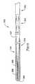
- FIG. 1a is a partial cross sectional fragmentary view of a guidewire 10 including a proximal guidewire section 14 and a distal guidewire section 16.
- the proximal section 14includes a distal end 24 and a proximal end 25, and the distal section 16 includes a proximal end 26 and a distal end 27.
- the guidewire 10includes a connection 20 joining the proximal guidewire section 14 and the distal guidewire section 16.
- the embodiment of Figure 1utilizes a joint 12 including a tubular connector 18.
- the guidewire 10can include a shaft or core portion that can be one continuous member, for example, the proximal guidewire section 14 and a distal guidewire section 16 may be continuous with one another and, collectively, define a continuous shaft or core.
- the guidewire 10can include a shaft or core portion that includes a plurality of sections connected by joints.
- the proximal section 14 and the distal section 16may generically refer to any two adjacent guidewire sections along any portion of the guidewire.
- proximal/distal guidewire sections 14/16are dictated primary by the desired characteristics and function of the final guidewire, and that any of a broad range of materials, structures, and dimensions can be used.
- the proximal and distal guidewire sections 14/16may be formed of any materials suitable for use, dependent upon the desired properties of the guidewire.
- suitable materialsinclude metals, metal alloys, polymers, or the like, or combinations or mixtures thereof.
- suitable metals and metal alloysinclude stainless steel, such as 304V, 304L, and 316L stainless steel; alloys including nickel-titanium alloy such as linear elastic or superelastic (i.e.
- pseudoelasticnitinol
- nickel-chromium alloynickel-chromium-iron alloy
- cobalt alloytungsten or tungsten alloys
- MP35-Nhaving a composition of about 35% Ni, 35% Co, 20% Cr, 9.75% Mo, a maximum 1% Fe, a maximum 1% Ti, a maximum 0.25% C, a maximum 0.15% Mn, and a maximum 0.15% Si
- hastelloymonel 400; inconel 625; or the like; or other suitable material, or combinations or alloys thereof.
- metals, or metal alloysthat are suitable for metal joining techniques such as welding, soldering, brazing, crimping, friction fitting, adhesive bonding, etc.
- nitinolwas coined by a group of researchers at the United States Naval Ordinance Laboratory (NOL) who were the first to observe the shape memory behavior of this material.
- NOLUnited States Naval Ordinance Laboratory
- the word nitinolis an acronym including the chemical symbol for nickel (Ni), the chemical symbol for titanium (Ti), and an acronym identifying the Naval Ordinance Laboratory (NOL).
- linear elasticwhich, although is similar in chemistry to conventional shape memory and superelastic (i.e. pseudoelastic) varieties, exhibits distinct and useful mechanical properties.
- the wireis fabricated in such a way that it does not display a substantial "superelastic plateau” or “flag region” in its stress/strain curve. Instead, as recoverable strain increases, the stress continues to increase in an essentially linear relationship until plastic deformation begins.
- the linear elastic nickel-titanium alloyis an alloy that does not show any martensite/austenite phase changes that are detectable by DSC and DMTA analysis over a large temperature range.
- the mechanical bending properties of such materialare therefore generally inert to the effect of temperature over this very broad range of temperature.
- the mechanical properties of the alloy at ambient or room temperatureare substantially the same as the mechanical properties at body temperature.
- the use of the linear elastic nickel-titanium alloyallows the guidewire to exhibit superior "pushability" around tortuous anatomy.
- the linear elastic nickel-titanium alloyis in the range of about 50 to about 60 weight percent nickel, with the remainder being essentially titanium. In some particular embodiments, the composition is in the range of about 54 to about 57 weight percent nickel.
- a suitable nickel-titanium alloyis FHP-NT alloy commercially available from Furukawa Techno Material Co. of Kanagawa, Japan.
- suitable nickel-titanium alloysinclude those disclosed in U.S. Patent Nos. 5,238,004 and 6,508,803 , which are incorporated herein by reference.
- a superelastic alloyfor example a superelastic nitinol can be used to achieve desired properties.
- the entire guidewire 10can be made of the same material, or in some embodiments, can include portions or sections, for example, proximal/distal guidewire sections 14/16, that are made of different materials.
- the material used to construct different portions of the guidewire 10can be chosen to impart varying flexibility and stiffness characteristics to different portions of the wire.
- the proximal guidewire section 14may be formed of relatively stiff material such as straightened 304v stainless steel wire.
- proximal portion 14may be comprised of a metal or metal alloy such as a nickel-titanium alloy, nickel-chromium alloy, nickel-chromium-iron alloy, cobalt alloy, or other suitable material.
- the material used to construct proximal portion 14may be selected to be relatively stiff for pushability and torqueability.
- the distal guidewire section 16may be formed of a relatively flexible material such as a straightened super elastic (i.e. pseudoelastic) or linear elastic alloy (e.g., nickel-titanium), or a alternatively, a polymer material, such as a high performance polymer.
- distal portion 16may include a metal or metal alloy such as stainless steel, nickel-chromium alloy, nickel-chromium-iron alloy, cobalt alloy, or other suitable material.
- the material used to construct distal portion 16may be selected to be relatively flexible for trackability.
- portions or all of the proximal/distal guidewire sections 14/16, or other structures included within the guidewire 10may also be doped with, coated or plated with, made of, or otherwise include a radiopaque material.
- Radiopaque materialsare understood to be materials capable of producing a relatively bright image on a fluoroscopy screen or another imaging technique during a medical procedure. This relatively bright image aids the user of guidewire 10 in determining its location.
- Some examples of radiopaque materialscan include, but are not limited to, gold, platinum, palladium, tantalum, tungsten alloy, polymer material loaded with a radiopaque filler, and the like, or combinations or alloys thereof.
- a degree of MRI compatibilityis imparted into guidewire 10.
- MRIMagnetic Resonance Imaging
- the proximal/distal guidewire sections 14/16, or portions thereofmay be made of a material that does not substantially distort the image and create substantial artifacts (artifacts are gaps in the image). Certain ferromagnetic materials, for example, may not be suitable because they may create artifacts in an MRI image.
- the proximal/distal guidewire sections 14/16, or portions thereof,may also be made from a material that the MRI machine can image. Some materials that exhibit these characteristics include, for example, tungsten, Elgiloy, MP35N, nitinol, and the like, and others, or combinations or alloys thereof.
- proximal/distal guidewire sections 14/16are typically dictated by the length and flexibility characteristics desired in the final medical device.
- proximal section 14may have a length in the range of about 20 to about 300 centimeters or more
- distal section 16may have a length in the range of about 3 to about 50 centimeters or more
- guidewire 10may have a total length in the range of about 25 to about 350 centimeters or more. It can be appreciated that alterations in the length of sections 14/16 and guidewire 10 can be made without departing from the spirit of the invention.
- Proximal/distal guidewire sections 14/16can have a solid cross-section, but in some embodiments, can have a hollow cross-section. In yet other embodiments, guidewire sections 14/16 can include combinations of areas having solid cross-sections and hollow cross sections. Moreover, guidewire sections 14/16 can be made of rounded wire, flattened ribbon, or other such structures having various cross-sectional geometries. The cross-sectional geometries along the length of guidewire sections 14/16 can also be constant or can vary. For example, Figure 1 depicts guidewire sections 14/16 as having a generally round cross-sectional shape. It can be appreciated that other cross-sectional shapes or combinations of shapes may be utilized without departing from the spirit of the invention. For example, the cross-sectional shape of guidewire sections 14/16 may be oval, rectangular, square, polygonal, and the like, or any suitable shape.
- guidewire sections 14/16may include one or more tapers or tapered regions.
- the tapered regionsmay be linearly tapered, tapered in a curvilinear fashion, uniformly tapered, non-uniformly tapered, or tapered in a stepwise fashion.
- the angle of any such taperscan vary, depending upon the desired flexibility characteristics.
- the length of the tapermay be selected to obtain a more (longer length) or less (shorter length) gradual transition in stiffness. It can be appreciated that essentially any portion of guidewire 10 and/or guidewire sections 14/16 may be tapered and the taper can be in either the proximal or the distal direction.
- the guidewire sections 14/16may include one or more portions where the outside diameter is narrowing, and portions where the outside diameter remains essentially constant.
- the number, arrangement, size, and length of the narrowing and constant diameter portionscan be varied to achieve the desired characteristics, such as flexibility and torque transmission characteristics.
- the tapered and constant diameter portions of the tapered regionmay be formed by any one of a number of different techniques, for example, by centerless grinding methods, stamping methods, and the like.
- the centerless grinding techniquemay utilize an indexing system employing sensors (e.g., optical/reflective, magnetic) to avoid excessive grinding of the connection.
- the centerless grinding techniquemay utilize a CBN or diamond abrasive grinding wheel that is well shaped and dressed to avoid grabbing core wire during the grinding process.
- distal shaft member 20can be centerless ground using a Royal Master HI-AC centerless grinder.
- the distal guidewire section 16includes three constant diameter regions 31, 33, and 35, interconnected by two tapering regions 37 and 39.
- the constant diameter regions 31, 33, and 35 and tapering regions 37 and 39are disposed such that the distal guidewire section 16 includes a geometry that decreases in cross sectional area toward the distal end thereof.
- these constant diameter regions 31, 33, and 35 and tapering regions 37 and 39are adapted and configured to obtain a transition in stiffness, and provide a desired flexibility characteristic.
- portions of the guidewire section 16can be flattened, for example, to provide for desired flexibility characteristics, or to provide an attachment point for other structure.
- constant diameter portion 35could include a portion thereof that is flattened.
- the distal guidewire section 16also includes tapered portion 41 and constant diameter portion 43 near its proximal end. This reduction in diameter near the proximal end is configured to accommodate the connector member 18 in this particular embodiment, as will be discussed in more detail below.
- the proximal section 14includes a proximal constant diameter portion 45, a distal constant diameter portion 47, and a taper portion 49 disposed there between. This reduction in diameter near the distal end the proximal section 14 is also configured to accommodate the connector member 18 in this particular embodiment, as will be discussed in more detail below.
- the distal section 16 of the guidewire 10can have a length in the range of about 3 to about 25 inches.
- the constant diameter regions 31, 33, and 35can have outer diameters in the range of about 0.01 to about 0.015, about 0.005 to about 0.012 and about 0.001 to about 0.005 inches respectively, and lengths in the range of about 1 to about 10, about 1 to about 10 and about 0.1 to about 2 inches, respectively.
- the tapering regions 37 and 39can have lengths in the range of about 0.5 to about 5, and about 0.5 to about 5 inches, respectively, and are generally linearly tapered.
- the constant diameter portion 43can have outer diameters in the range of about 0.005 to about 0.012 inches, and a length in the range of about 0.02 to about 1.5 inches.
- the tapered portion 41can have a length in the range of about 0.02 to about 1 inches, and can be generally linearly tapered.
- a portion of the constant diameter portion 35can be flattened, for example, the distal most about 0.05 to about 1 inch of the constant diameter portion 35 can be flattened to define generally parallel opposed surfaces, and to have a thickness in the range of about 0.0005 to about 0.0025 inches.
- the proximal section 14 of the guidewire 10can have a length in the range of about 30 to about 150 inches.
- the constant diameter regions 45, and 47can have outer diameters in the range of about 0.01 to about 0.015 and about 0.005 to about 0.012 inches, respectively, and lengths in the range of about 30 to about 150, and about 0.02 to about 1.5 inches, respectively.
- the tapering section 49can have a length in the range of about 0.02 to about 1 inch, and can be generally linearly tapered.
- the proximal guidewire section 14is formed from a stainless steel wire
- the distal guidewire section 16is formed from a linear elastic nitinol wire.
- the distal end 24 of the proximal portion 14 and the proximal end 26 of distal portion 16may form a joint 12.
- Some methods and structures that can be used to interconnect different shaft sectionsare disclosed in U.S. Patent Application Nos. 09/972,276 , and 10/086,992 .
- the joined ends 24/26are spaced, as shown in Figure 1 . In some embodiments, the joined ends 24/26 can be spaced a distance in the range of about 0 to about 1.5 inches within the connector member 18. Alternatively, the joined ends 24/26 may form a touching but joint, an overlapping tapered joint 12, an overlapping joint 12 that is not tapered, or the like.
- the end portions 24/26may have a uniform profile (diameter), a bulbous portion for purposes of mechanical interlocking and the like, or a helical form for purposes of mechanical interlocking or the like.
- the overlapping jointcan function to blend the stiffness of proximal portion 14 and distal portion 16 by combining the properties of each end section 24/26 making up the cross section of the overlapping joint.
- the joint 12can form a flexibility transition region that has a relative flexibility that is between the flexibility of the distal end 24 of the proximal portion 14 and the flexibility of the proximal end 26 of the distal portion 16.
- the proximal guidewire section 14 and the distal guidewire section 16may be formed of different materials (i.e., materials having different moduli of elasticity) resulting in a difference in flexibility.
- the proximal guidewire section 14may be formed of stainless steel wire and the distal guidewire section 16 may be formed of nickel-titanium alloy wire, both having the same dimensions near the joint, resulting in a 3:1 difference in elastic modulus.
- Such a difference in elastic modulusi.e., flexibility
- stressis distributed along the entire length of the connection 20 thereby decreasing the probability that guidewire 10 may kink at the junction.
- connection 20may be located further distally.
- the distal portion 16may be manufactured to be shorter than proximal portion 14. Including a relatively long proximal section 14 may advantageously increase the torquability and pushability of the guidewire 10.
- additional connections 20may be used to connect other guidewire sections of varying stiffness.
- the connector 18may comprise a tubular structure such as a hypotube as shown or a coiled wire.
- the connector 18may have an inside diameter sized appropriately to receive the ends 24/26 of the proximal portion 14 and the distal portion 16, and an outside diameter sufficient to accommodate a final grinding procedure.
- the connector 18can have an inner diameter in the range of about 0.004 to about 0.02 inches, and an outer diameter in the range of about 0.01 to about 0.02 inches.
- the final diameter of the guidewire 10 and the connector 18may be in the range of 0.010 to 0.018 inches, for example.
- the connector 18may have a length of about 0.03 to 3.0 inches.
- this type of constructioncan be applied to wires of larger diameter intended, for example, for peripheral intervention purposes.
- wirescould range as large as .035 inche in diameter or larger, and therefore have an extended length connector and correspondingly longer overlapping sections.
- the diameters given, as with the other specific dimensional information given herein,are by way of example only.
- the lateral flexibility, bendability or other such characteristics of the connector 18can be achieved or enhanced in a number of ways.
- the materials selected for the connector 18may be chosen so that the connector 18 has a desired lateral flexibility.
- the connector 18may be formed of materials having a different modulus of elasticity than the adjacent portions of the guidewire members 14/16, resulting in a difference in flexibility.
- the desired lateral flexibility or bending characteristicscan be imparted or enhanced by the structure of the connector 18.
- a plurality of grooves, cuts, slits, or slotscan be formed in a tubular connector 18. Such structure may be desirable because they may allow connector 18 to be bendable as well as transmit torque and pushing forces from proximal section 14 to distal section 16.
- the cuts or slots or groovescan be formed in essentially any known way.
- cuts, grooves or slotscan be formed by mechanical methods, such as micro machining, saw cutting, LASER cutting, chemically etching, treating or milling, casting, molding, other known methods, and the like.
- cuts, grooves, or slotscan completely penetrate connector 18.
- cuts, grooves, or slotsmay only partially extend into connector 18, or include combinations of both complete and partial cuts.
- the cuts, grooves, or slotsmay be formed such that one or more spines, splines, or beams are formed in the tubular connector 18.
- Such spines or beamscould include portions of the tubular member that remain after the cuts or slots are formed in the body of the tubular member.
- Such spines or beamscan act to maintain a relatively high degree of tortional stiffness, while maintaining a desired level of lateral flexibility.
- some adjacent cuts or slotscan be formed such that they include portions that overlap with each other about the circumference of the tube.
- some adjacent slots or cutscan be disposed such that they do not necessarily overlap with each other, but are disposed in a pattern that provides the desired degree of lateral flexibility.
- the size, shape, spacing, or orientation of the cuts or slots, or in some embodiments, the associated spines or beams,can be varied to achieve the desired lateral flexibility and/or tortional rigidity characteristics of the connector 18.
- the number or density of the cuts or slots along the length of the connector 18may vary, depending upon the desired characteristics. For example, the number or proximity of slots to one another near the midpoint of the length of the connector 18 may be high, while the number or proximity of slots to one another near either the distal or proximal end of the connector 18, or both, may be relatively low, or vice versa.
- the connector 18may be made of or include a metal, metal alloy, polymer, metal-polymer composite, or the like, as discussed above with regard to the guidewire sections 14/16, and may include radiopaque materials or include materials or structure to impart a degree of MRI compatibility, as discussed above with regard to the guidewire sections 14/16.
- alloysare particularly suitable for connector 18 for some purposes, for example, for connecting a stainless steel proximal section 14 and a nickel titanium alloy distal section 16, or visa-versa.
- An exampleis a nickel-chromium-iron alloy designated UNS N06625 and is available under the trade name INCONEL 625, which advantageously welds to both stainless steels and nickel-titanium alloys.
- INCONEL 625 wiremay be obtained from California Fine Wire Company of Grover Beach, California.
- Another example of a suitable alloy which welds to both stainless steels and nickel-titanium alloysis designated UNS 10276 and is available under the trade name ALLOY C276 from Fort Wayne Metals Research Products Corporation of Fort Wayne, Indiana.
- a suitable alloy which welds to both stainless steels and nickel-titanium alloysis of the Hastelloy family and an example of which is available under the trade name ALLOY B2 from Fort Wayne Metals Research Products Corporation of Fort Wayne, Indiana.
- ALLOY B2Fort Wayne Metals Research Products Corporation of Fort Wayne, Indiana.
- the ends 24/26 of the proximal and distal guidewire sections 14/16may be ground to form the desired shape to accommodate the connector.
- a recess stepsuch as constant diameter portions 43/47 and taper portions 41/49 may be ground or otherwise formed into the proximal and distal guidewire sections 14/16 to accommodate the connector tube 18. If a connector tube 18 is not to be used, such a recess step need not be ground.
- the connector tube 18is positioned over one of the ends 24/26 of the proximal and distal guidewire sections 14/16.
- the proximal and distal guidewire sections 14/16 and the connector tube 18may be bonded, welded (e.g., resistance or LASER welded), soldered (e.g. LASER diode soldering), brazed, or otherwise connected by a suitable technique depending on the material selected for each component.
- securing the connector 18 to the proximal and distal sections 14/16may include the use of a connector and/or an expandable alloy, for example, a bismuth alloy.
- the ends 24/26 and the connector tube 18may be crimped together or may be sized to establish a friction fit therebetween. If a connector tube 18 is not used, the ends 24/26 may be bonded, welded (e.g., resistance or LASER welded), soldered, brazed, or otherwise connected, using a connector material. Connector material may be the same as or similar to the material of the connector 18. In all cases, because the connection 20 may reside within a catheter lumen or within the anatomy during use, it is preferred that a permanent connection (as opposed to a releasable connection) be used.
- the connector 18is welded to proximal and distal guidewire sections 14/16. It is to be appreciated that various welding processes can be utilized. In general, welding refers to a process in which two materials such as metal or metal alloys are joined together by heating the two materials sufficiently to at least partially melt adjoining surfaces of each material. A variety of heat sources can be used to melt the adjoining materials. Examples of welding processes that can be suitable in some embodiments include LASER welding, resistance welding, TIG welding, microplasma welding, electron beam, and friction or inertia welding.
- LASER welding equipmentwhich may be suitable in some applications is commercially available from Unitek Miyachi of Monrovia, California and Rofin-Sinar Incorporated of National, Michigan. Resistance welding equipment which may be suitable in some applications is commercially available from Palomar Products Incorporated of Carlsbad, California and Polaris Electronics of Olathe, Kansas. TIG welding equipment which may be suitable in some applications is commercially available from Weldlogic Incorporated of Newbury Park, California. Microplasma welding equipment which may be suitable in some applications is commercially available from Process Welding Systems Incorporated of Smyma, Tennessee.
- LASER or plasma weldingcan be used to secure the connector 18 and the proximal and distal guidewire sections 14/16 securely together.
- a light beamis used to supply the necessary heat.
- LASER weldingcan be beneficial in the processes contemplated by the invention, as the use of a LASER light heat source can provide pinpoint accuracy. It should also be understood that such LASER welding can also be used to attach other components of the guidewire, as discussed below.
- LASER energycan be used as the heat source for soldering, brazing, or the like for attaching different components or structures of the guidewire together.
- a LASERas a heat source for such connection techniques can be beneficial, as the use of a LASER light heat source can provide pinpoint accuracy.
- LASER diode solderingincludes LASER diode soldering.
- connectioncan extend around the entire circumference of the connector 18 and the proximal and distal guidewire sections 14/16. In some other embodiments, however, one or more spaced connection points can be made around the circumference of the proximal and distal guidewire sections 14/16.
- attachment techniquesfor example laser welding or laser diode soldering, or the like, can be useful in making connections around only a portion of the circumference because they tend to allow the accuracy needed to make such connections.
- the connector tube 18 and the proximal and distal guidewire sections 14/16can be centerless ground or otherwise shaped or formed as desired to provide the desired characteristics, for example, a smooth and uniform profile across the connection 20, or to straighten out small misalignments between the proximal and distal guidewire sections 14/16.
- Other portions of the guidewire 10may be ground as well to provide the desired tapers and changes in diameter.
- a flexible coil tip and/or a polymer jacket tip (optionally covering connection 20) or combination thereof, and other such structure, such as radiopaque markers, safety and/or shaping ribbons (coiled or uncoiled), and the like,may be placed on the guidewire 10.
- additional components and tip constructionsare disclosed in U.S. Patent Application Nos. 09/972,276 , and 10/086,992 .
- a coatingfor example a lubricious (e.g., hydrophylic) or other type of coating may be applied to all or portions of the guidewire. Different coatings can be applied to different sections of the guidewire.
- a coatings and materials and methods used to create such coatingscan be found in U.S. Patent Nos. 6,139,510 and 5,772,609 .
- the embodiment in Figure 1includes a wire or ribbon 58 that is attached adjacent the distal end 27 of the distal section 16, and extends distally of the distal end 27.
- the wire or ribbon 58can be a fabricated or formed wire structure, for example a coiled wire.
- the ribbon 58is a generally straight ribbon that overlaps with and is attached to the distal end 27 of the distal section 16.
- the ribbon 58can be made of any suitable material and sized appropriately to give the desired characteristics, such as strength and flexibility characteristics.
- suitable materialsinclude metals, metal alloys, polymers, and the like, and may include radiopaque materials or include materials or structure to impart a degree of MRI compatibility, as discussed above in relation to the proximal and distal guidewire sections 14/16, and in relation to the connector 18.
- the ribbon 58is a flattened ribbon having a width in the range of about 0.002 to about 0.008 inches, a thickness in the rang of about 0.0005 to about 0.003 inches, and a length in the range of about 0.25 to about 3 inches. In some embodiments, the ribbon 58 overlaps with the distal section 16 by a length in the range of about 0.25 to about 2 inches, and includes a distal portion that extends distally beyond the distal section 16 by a length in the range of about 0.1 to about 2 inches.
- the ribbon 58can be attached to the distal section 16 using any suitable attachment technique.
- attachment techniquesinclude soldering, brazing, welding, adhesive bonding, crimping, or the like.
- the ribbon or wire 58can function as a shaping structure or a safety structure.
- the distal end of the ribbon 58can be free of attachment, or can be attached to another structure, for example a tip portion 69, for example, a rounded tip portion.
- the tip portion 69can be made or formed of any suitable material, for example a solder tip, a polymer tip, a welded tip, and the like, using suitable techniques.
- the ribbon 58is attached to the distal section 16 adjacent the distal end 27 thereof at two attachment points, 59 and 61.
- Attachment point 59is disposed adjacent constant diameter region 35, which may or may not be flattened, as discussed above.
- the attachment point 59is disposed at the very distal end 27 of the distal section 16, while in other embodiments, the attachment point can be spaced more proximally form the very distal end 27.
- attachment adjacent the very distal end 27is used such that the distal end 27 of the section 16 and the ribbon can flex as one connected or integral unit. Such an arrangement can provide for desirable trackability characteristics, and can provide for desirable tip resiliency characteristics.
- Attachment point 61is disposed adjacent tapering region 39. It should be understood, however, that these attachment points and attachment techniques are given by way of example only, and that the ribbon can be attached at different locations and by using more or fewer attachment points, and a variety of attachment techniques, as desired, without parting from the spirit and scope of the invention.
- Figures 3-5are close up cross sectional views of the guidewire of Figure 1 about attachment point 59.
- the ribbon 58is attached to the constant diameter region 35 adjacent the distal end 27 of the distal section 16 using a heat activated attachment material, for example a solder material 63, a brazing material, or other such material.
- a heat activated attachment materialfor example a solder material 63, a brazing material, or other such material.
- Such attachment materialcan be
- Figure 3is included to illustrate the use of a broad heat source, for example, a radiant heat source, to heat and activate the solder material 63 to make the connection.
- the dotted linesindicate the area that might be heated using such radiant heat energy. As can be seen, the entire area surrounding the attachment point 59 would be heated. In some embodiments, this can be undesirable.
- the heatmay adversely affect the characteristics of the material.
- One example of such materialsinclude some nickel titanium alloys, which if exposed to undue heat above a certain point, may undergo a phase change, or may anneal, which may effect the desired properties of the material.
- Figure 4is similar to Figure 3 , but is included to illustrate the use of a narrower, or more controlled heat source, for example, light source energy, to heat the solder 63, wherein the dotted lines indicate the area that might be heated using light source energy.
- a narrower, or more controlled heat sourcefor example, light source energy
- the light source energymay still undesirably heat areas surrounding the attachment point 59.
- Figure 5is similar to Figures 3 and 4 , but is included to illustrate the use of an even narrower, or more controlled heat source, for example, a LASER energy source, to heat the solder 63, wherein the dotted lines indicate the area that might be heated using LASER source energy.
- a LASER energy sourcefor example, a LASER energy source
- the area affectedis narrower than using a radiant heat source, or light source energy. Therefore, the use of LASER energy may be desirable to avoid undesirably heating larger areas surrounding the attachment point 59.
- the use of a LASER as a heat source in soldering, brazing, and the like,can be beneficial in the processes contemplated by the invention, as the use of a LASER light heat source can provide pinpoint accuracy.
- LASER soldering or brazingcan also be used to attach other components of the guidewire.
- One additional example of a process that uses LASER energyis diode soldering, which can also be used.
- the structures being connectedcan be pre-treated and/or precoated with a suitable attachment material prior to attachment.
- the ribbon 58, or portions thereof, and/or the distal section 16, or portions thereof, or bothcan be cleaned or treated to remove impurities or oxides. This can be useful, especially when one or both of the materials being connected is a difficult material to solder or braze to, such as some nickel titanium alloys.
- Such treatmentsinclude acid baths or washes, fluxing, pickling, pre-tinning, pre-plating (i.e. plating with another material) and the like.
- one or both of the surfaces to be connectedcan be cleaned and pre-plated with another metallic material, for example, a nickel plating.
- the surface to be soldered or brazedis treated with a molten alkali metal hydroxide, and then pre-treated, or "pre-tinned" with a suitable solder or brazing material.
- heat activated attachment materialsuch as solder or brazing material
- solder or brazing materialcan be predisposed on the components being connected using such processes or treatments, or can be separately disposed or added to make the connection. Therefore, the heat activated attachment material used for making such connections can come form either source (“pre-tinned” or “added"), or from both sources.
- the heat activated attachment materialcan include any suitable, brazing material, or the like.
- suitable solder or brazing materialinclude, but are not limited to, tin based materials, for example, gold-tin solder, silver -tin solder, and the like, and many others.
- Figures 6-8are close up cross sectional views of the distal guidewire section 16 of the of Figure 1 at attachment point 61 prior to and during an attachment procedure.
- Figure 8is a close up cross sectional view of the distal guidewire section 16 of Figure 1 at attachment point 61 after attachment of the ribbon 58 to the distal section 16.
- the ribbon 58is being attached to the tapering region 39 adjacent the distal end 27 of the distal section 16 using a heat activated attachment material, for example a solder 63, a brazing material, or other such material.
- a heat activated attachment materialfor example a solder 63, a brazing material, or other such material.
- an attachment or centering ring 65is also being attached to the tapering region 39.
- Figure 6shows an attachment or centering ring 65 that is disposed about the distal section 16, and the ribbon 58 is disposed between the centering ring 65 and the distal section 16.
- the centering ring 65can be a generally tubular member that is adapted or configured to fit over a portion of the distal section 16, and in at least some embodiments, is adapted or configured to attach to the ribbon 58 and the distal section 16. Additionally, the centering ring 65 can be adapted and configured to attach to an outer member, such as a coil 80, as discussed in more detail below.
- heat activated bonding or filler materialsuch as solder material 63, can be disposed adjacent to the centering ring 65 prior to attachment, as shown in Figure 6 .
- solder material 63can be disposed about the distal section 16, adjacent to the centering ring 65 and the ribbon 58. It should be understood however, that in other embodiments, the solder material 63 can be disposed or located at a different location than shown, for example, adjacent the proximal side of the centering ring 65, or alternatively, could be disposed in the desired attachment positions between the members to be connected prior to connection.
- the solder material 63can then be heated using an appropriate heat source, and it will begin to flow into an attachment position between the ribbon and the distal section 16, and/or between the ribbon 58 and the centering ring 65, and/or between the distal section 16 and the centering ring 65, or all of the above positions.
- suitable heat sources for use in soldering or brazingare described above.
- LASER energyis used as the heat source to provide for accuracy of heating, and to avoid undesirable heating of structures adjacent the attachment points.
- Figure 8shows the solder material 63 disposed in attachment positions that connect the ribbon 58 to the distal section 16, connect the ribbon 58 to the centering ring 65, and connect the distal section 16 to the centering ring 65.
- Figure 8also shows a coil 80 that has been attached to the centering ring 65, as will be discussed in more detail below.
- attachment techniquesare merely illustrative, and that other suitable attachment techniques or structures can be used.
- the attachment techniques described abovecan be used at other locations along the length of the guidewire, or can be used to attach other components of the guidewire to each other.
- a ringsuch as attachment or centering ring 65, can be used to attach coils, ribbons, braids, wires, or the like, or other such structures to the proximal or distal guidewire sections 14/16.
- soldering or brazing techniquesfor example, the use of LASER energy as the heat source, can be used in attaching additional structures to proximal or distal guidewire sections 14/16.
- the embodiment in Figure 1also includes a coil 80 disposed about at least a portion of the proximal and/or distal guidewire sections 14/16.
- the coil 80can extend about the distal sections 16 from a point adjacent the tapering region 37 distally to a point beyond the distal most portion of the distal section 16.
- the coil 80is attached to the distal guidewire section 16 at its proximal end 81 at attachment point 83 using any suitable attachment technique, for example soldering, brazing, welding, adhesive bonding, crimping, or the like.
- the distal end 85 of the coil 80can be attached to the ribbon 58 via the rounded tip portion 69.
- the rounded tip portion 29can be made of any suitable material, for example a solder tip, a polymer tip, and the like.
- the distal end 85may be attached to other structure, for example, a spacer member or attachment or centering ring, or may be free of attachment.
- the coil 80can be attached at one or more intermediate points, for example, to the centering or attachment ring 65.
- the centering ring 65can function to attach the coil 80 to the guidewire section 16, and can also function to somewhat maintain the axial and lateral position of the coil 80 relative to the guidewire section 16. Attachment to the centering ring 64 can also be performed using any suitable attachment technique, for example soldering (e.g. LASER diode soldering), brazing, welding, adhesive bonding, crimping, or the like.
- the coil 80can be attached at different locations and by using more or fewer attachment points, as desired, without parting from the spirit and scope of the invention. Additionally, in other embodiments, the coil 80 can be disposed at other locations along the length of the guidewire 10, or could extend the entire length of the guidewire 10.
- attachment of the coil 80 at either attachment point 83, at centering or attachment ring 65, or at other locations along the length of the guidewire 10can be achieved using a welding process, for example, LASER or plasma welding. Any of the above described material, structure, techniques or equipment can be used. As described above, in LASER welding, a light beam is used to supply the necessary heat. LASER welding can be beneficial in the processes contemplated by the invention, as the use of a LASER light heat source can provide pinpoint accuracy. It should also be understood that such LASER welding can also be used to attach other components of the guidewire, as discussed above.
- connection of the coil 80 at either attachment point 83, or at centering ring 65can extend around the entire circumference of the coil 80. In some other embodiments, however, one or more spaced connection points that do not extend all the way around the circumference of the coil 80 can be made.
- the use of certain attachment techniques, for example laser welding or laser diode soldering, or the like,can be useful in making connections around only a portion of the circumference coil 80 because they tend to allow the accuracy needed to make such connections.
- connections around only a portion of the circumference coil 80can allow for some desired characteristics, such as increased flexibility of the coil 80.
- a transition structure or layercan be disposed on the distal guidewire section 16 just proximal of the attachment point 83 to provide for a smooth transition between the outer surface of the distal section 16 and the coil 80.
- Any suitable materialcan be used, for example, an adhesive, a polymer, solder, or other such material.
- the coil 80may be made of a variety of materials including metals, metal alloys, polymers, and the like, including those described above with regard to the guidewire sections 14/16, the connector 18, and the ribbon 58.
- suitable materialsinclude stainless steel, such as 304V, 304L, and 316L stainless steel; alloys including nickel-titanium alloy such as linear elastic or superelastic (i.e.
- pseudoelasticnitinol
- nickel-chromium alloynickel-chromium-iron alloy
- cobalt alloytungsten or tungsten alloys
- MP35-Nhaving a composition of about 35% Ni, 35% Co, 20% Cr, 9.75% Mo, a maximum 1% Fe, a maximum 1% Ti, a maximum 0.25% C, a maximum 0.15% Mn, and a maximum 0.15% Si
- hastelloymonel 400; inconel 625; or the like; or other suitable material.
- the coil 80can be made of, coated or plated with, or otherwise include a radiopaque material such as gold, platinum, tungsten, or the like, or combinations or alloys thereof, or polymer materials including radiopaque materials. Additionally, the coil can include materials or structure to impart a degree of MRI compatibility, as discussed above in relation to the guidewire sections 14/16, the connector 18, and the ribbon 58.
- Figure 14which is a cross sectional fragmentary view of an example coil 590 that can be used in medical devices, such as guidewires, wherein the coil 590 includes an inner portion, layer, or wire 510 that includes or is made of a first material, and an outer portion, layer, or wire 511 that includes or is made of a second material.
- the inner portion 510could be a wire or ribbon as discussed above
- the outer portion 511could be a coating, cladding, plating, or extrusion of a radiopaque material or an MRI compatible imaging material, as discussed above.
- the coil 80may be formed of round wire or flat ribbon ranging in dimensions to achieve the desired flexibility. It can also be appreciated that other cross-sectional shapes or combinations of shapes may be utilized without departing from the spirit of the invention.
- the cross-sectional shape of wires or filaments used to make the coilmay be oval, rectangular, square, triangle, polygonal, and the like, or any suitable shape.
- the coil 80can be wrapped in a helical fashion by conventional winding techniques.
- the pitch of adjacent turns of coil 80may be tightly wrapped so that each turn touches the succeeding turn or the pitch may be set such that coil 80 is wrapped in an open fashion.
- the coilcan have a pitch of up to about 0.04 inches, in some embodiments a pitch of up to about 0.02 inches, and in some embodiments, a pitch in the range of about 0.001 to about 0.004 inches.
- the pitchcan be constant throughout the length of the coil 458, or can vary, depending upon the desired characteristics, for example flexibility.
- These changes in coil pitchcan be achieved during the initial winding of the wire, or can be achieved by manipulating the coil after winding or after attachment to the guidewire. For example, in some embodiments, after attachment of the coil 80 to the guidewire 10, a larger pitch can be achieved on the distal portion of the coil 80 by simply pulling the coil.
- portions or all of the coil 80can include coil windings that are pre-tensioned or pre-loaded during wrapping, such that each adjacent coil winding is biased against the other adjacent coil windings to form a tight wrap. Such preloading could be imparted over portions of, or over the entire length of the coil 80.
- the diameter of the coil 80is preferably sized to fit around and mate with the guidewire 10, and to give the desired characteristics.
- the diameter of the coil 80can be constant or tapered.
- the coil 80is tapered, for example, to mate with a tapered section of the guidewire 10, or with other structure.
- the diameter of the coil 80can also include a taper beyond the distal end of the guidewire section 16, as desired.
- the coil 80can be in the range of about 1 to about 20 inches long, and is made of rounded wire having a diameter of about 0.001 to about 0.004 inches.
- the coil 80can have an outer diameter that is generally constant, and is in the range of about 0.01 to about 0.015 inches.
- the inner diameter of the coilcan also be generally constant, and is in the range of about 0.004 to about 0.013 inches.
- the pitch of the coil 80can be in the range of about 0.0005 to about 0.05 inches.
- the guidewire 10also includes an inner coil 90 to form a dual coil tip construction in accordance with the invention.
- the inner coil 90is disposed about the distal end portion 27 of the distal guidewire section 16, and is disposed within the lumen of the outer coil 80.
- the inner coil 90can be made of the same materials, and have the same general construction and pitch spacing as discussed above with regard to the outer coil 80.
- the inner coilwould include an outer diameter that allows it to fit within the lumen of the outer coil 80, and in some embodiments, has an outer diameter that allows it be disposed in a relatively snug or tight fit with the inner diameter of the outer coil 80.
- the inner coil 90can be made of a radiopaque wire, for example, a platinum/tungsten wire, while the outer coil is made of a less radiopaque material, for example, MP35-N, or vice versa.
- the inner coil 90is disposed about the distal guidewire section 16 from about the middle of the constant diameter section 35, about the ribbon 58, and to a position adjacent the tip portion 69.
- the coil 90is attached to the outer coil 80 at proximal attachment point 93 using any suitable attachment technique, for example soldering, brazing, welding, adhesive bonding, friction fitting, or the like.
- the distal end 97 of the coil 90is free of attachment.
- distal end 97 of the coil 90can be attached to the outer coil 80, or can be attached to other structure, for example, to the tip portion 69, to a centering or attachment ring, or other such structure.
- the inner coil 90is attached only to the outer coil 80 at one or more attachment points, and is essentially free of any other connection to a core wire, or in some cases, is free of connection to any other structure in the guidewire 10 other than the outer coil 80.
- the inner coil 90can be attached to the outer coil 80 along the entire length of the inner coil 90, or only along a portion of the length thereof.
- the inner coil 90is attached only at the proximally disposed attachment point 93.
- the coil 90may be attached using other arrangements, for example, a distally disposed attachment point, or a combination of proximally and distally disposed attachment points. Attachment of the inner coil 90 to the outer coil 80 can be achieved using any suitable attachment technique, for example soldering (e.g. LASER diode soldering), brazing, welding, adhesive bonding, friction fitting, or the like.
- solderinge.g. LASER diode soldering
- attachment of the inner coil 90 to the outer coil 80can be made in any suitable manner, as discussed above, in some embodiments, attachment of the inner coil 90 to the outer coil 80 can be achieved using a welding process, for example, LASER or plasma welding. Any of the above described material, structure, techniques or equipment can be used. As described above, in LASER welding, a light beam is used to supply the necessary heat. LASER welding can be beneficial in the processes contemplated by the invention, as the use of a LASER light heat source can provide pinpoint accuracy. It should also be understood that such LASER welding can also be used to attach other components of the guidewire, as discussed above.
- a welding processfor example, LASER or plasma welding. Any of the above described material, structure, techniques or equipment can be used.
- LASER weldinga light beam is used to supply the necessary heat.
- LASER weldingcan be beneficial in the processes contemplated by the invention, as the use of a LASER light heat source can provide pinpoint accuracy. It should also be understood that such LASER welding can also be used to attach other components of
- the attachment of the inner coil 90 to the outer coil 80can extend around the entire circumference of the coils 80 and 90. In some other embodiments, however, one or more spaced connection points that do not extend all the way around the circumference of the coils 80 and 90 can be made.
- the use of certain attachment techniques, for example laser welding or laser diode soldering, or the like,can be useful in making connections around only a portion of the circumference coils 80 and 90 because they tend to allow the accuracy needed to make such connections.
- connections around only a portion of the circumference of the coils 80 and 90can allow for some desired characteristics, such as increased flexibility of the coils 80 and 90.
- the inner coil 90can be in the range of about 0.1 to about 3 inches long, and is made of rounded wire having a diameter of about 0.001 to about 0.005 inches.
- the coil 90can have an outer diameter that is generally constant, and is in the range of about 0.002 to about 0.015 inches.
- the inner diameter of the coilcan also be generally constant, and is in the range of about 0.001 to about 0.008 inches.
- the pitch of the coil 90can be in the range of about 0.0005 to about 0.04 inches.
- the inner coil 90is attached only to the outer coil 80 at one or more attachment points, and is essentially free of any other connection to a core wire, or in some cases, is free of connection to any other structure in the guidewire 10.
- Some such embodimentscan provide the benefit of one or more additional coils, for example coil 90, disposed within the guidewire structure without the need to attach such coils to a shaft or core wire.
- FIG. 9is a cross sectional fragmentary view of an example coil construction 110 that can be used in medical devices which is very similar to that described above with regard to Figure 1 .
- the coil construction 110includes an inner coil 190 attached to an outer coil 180 at one or more attachment points, for example, attachment point 193.
- the two coil members 180 and 190can be made of the same materials, and have the same general construction and pitch spacing as discussed above with regard to the outer coil 80 and inner coil 90. In some other embodiments, additional coil members could be connected to the outer coil 180.
- the inner coil 190could be configured for attachment to a medical device, such as a guidewire, and one or more outer coils 180 could be attached to the inner coil 190, and be essentially free of any other attachment to the medical device.
- a medical devicesuch as a guidewire
- any such coil arrangementcould be incorporated into a medical device construction by attaching only one of the coils to the medical device, while the other coils could be essentially free of any other attachment other than to the coil that is attached to the medical device.
- the attachment of the coil members, for example 180 and 190, to one anothercan be achieved using any suitable attachment technique, for example soldering, brazing, welding, adhesive bonding, friction fitting, or the like, wherein in some embodiments, welding, such as LASER or plasma welding are particularly used.
- FIG 10is an alternative embodiment of a coil construction 210 including an inner coil 290 attached to an outer coil 280 by an intermediate attachment member 285 that interconnects the two coil members 280 and 290.
- the two coil members 280 and 290can be made of the same materials, and have the same general construction and pitch spacing as discussed above with regard to the outer coil 80 and inner coil 90.
- the intermediate member 285can be any structure generally disposed between and being connected to the two coil members 280 and 290.
- the intermediate structure 285can be a generally tubular structure disposed around inner coil 290, and disposed within outer coil 280.
- a broad variety of other structurescould be used.
- the intermediate structure 285may be made of a variety of materials including metals, metal alloys, polymers, and the like, including those described above with regard to the guidewire sections 14/16, the connector 18, the ribbon 58, and the coils 180 and 190.
- the intermediate structure 285can be made of, coated or plated with, or otherwise include a radiopaque material and/or can include materials or structure to impart a degree of MRI compatibility, as discussed above in relation to the guidewire sections 14/16, the connector 18, the ribbon 58 and the coils 180 and 190.
- the attachment of the coil members, for example 280 and 290, to the intermediate member 285can be achieved using any suitable attachment technique, for example soldering, brazing, welding, adhesive bonding, friction fitting, or the like, wherein in some embodiments, welding, such as LASER or plasma welding are particularly used.
- weldingsuch as LASER or plasma welding are particularly used.
- FIG 11shows another alternative coil construction 310 including a first coil 390 attached to a second coil 380 at an attachment point 393.
- the first coil 390could be adapted or configured for attachment to a medical device, for example, for attachment to a core wire or shaft 312 of a guidewire.
- a proximal portion 391 of the first coil 390could be attached to a core wire or shaft 312, and the core wire or shaft 312 could extend within the lumen of the first coil 390.
- the first coil 390could include a first constant diameter portion 381, a tapered portion 383, and a second, narrower, constant diameter portion 385.
- the second coil 380could be adapted or configured to extend about at least a portion of the tapered portion 383, and the second, narrower, constant diameter portion 385.
- the attachment point 393could be adjacent the tapered portion 383.
- the second coil 390could be essentially free of attachment to any other portion of the guidewire other than the first coil 380.
- a distal portion 371 of the second coil 390could be free, or could be attached to the first coil 380 at a point more distally than is shown. In other embodiments, however, it is contemplated that the distal portion 371 of the second coil 390 could be connected to other structure.
- FIG. 12shows an example for alternative coil construction 410, not falling within the scope of the invention, including a coil 489 including a first inner portion 490 and a second outer portion 480.
- the coil 489is a continuous filament that has been wound into the coil construction including the inner and outer portions 490/480.
- a coil constructioncan be achieved by first winding a coil filament to create the inner portion 490 at a desired diameter, and then reversing the winding of the filament so as to wind the filament around the inner portion 490 to form the outer portion 480.
- the point of reversalcould form a tip portion 495.
- Such a winding techniquecould be accomplished using standard coil winding equipment.
- the two coil portions 480 and 490can be attached to each other at one or more point or portion along the length of the coil 490, or along the entire length of the coil 490. Such attachment can be made using any suitable attachment technique, for example soldering, brazing, welding, adhesive bonding, friction fitting, or the like, wherein in some embodiments, welding, such as LASER or plasma welding are particularly used.
- weldingsuch as LASER or plasma welding are particularly used.
- the two coil portions 480 and 490can be made of the same materials, and have the same general construction and pitch spacing as discussed above with regard to the outer coil 80 and inner coil 90.
- such a coil construction 410can be incorporated into a medical device, for example, for attachment to a core wire or shaft 412 of a guidewire.
- the tip portion 495 of the coil construction 410could be attached to a distal tip structure 469 of a guidewire, which in turn is attached to a ribbon 458 which in turn is attached to the core wire or shaft 412.
- a proximal portion 491 of the outer portion 480could be free, or could be attached to other structure, for example, to the core wire or shaft 412 at a point more proximally than is shown.
- FIG. 2shows a guidewire 10 very similar to that shown in Figure 1 , wherein like reference numerals indicate similar structure as discussed above.
- the proximal/distal guidewire sections 14/16, the connection 20, the joint 12, and the tubular connector 18 shown in the embodiment of Figure 2can also include the same general construction, structure, materials, and methods of construction as discussed above with regard to like components in the embodiments of Figure 1 .
- the distal tip portion of the guidewire 10 of Figure 2is also very similar to that shown in Figure 1 , wherein like reference numerals indicate similar structure. In the embodiment shown in Figure 2 , however, two radiopaque marker members 51 and 53 are attached to the distal guidewire section 16.
- the markers 51 and 53are made of, are coated or plated with, or otherwise include radiopaque materials that are capable of producing a relatively bright image on a fluoroscopy screen or another imaging technique during a medical procedure, as discussed above.
- Such markers 51 and 53can be structures such as bands, coils, and the like, and can be attached to the proximal or distal sections 14/16 in any suitable attachment technique, for example, soldering, brazing, welding, adhesive bonding, friction fitting, or the like.
- the distal guidewire section 16can include constant diameter portions chat are ground or otherwise formed therein for placement of the markers.
- the position of the markers 51 and 53 in relation to other structures within the guidewirecan vary widely, depending upon the desired ability to image the guidewire at certain points along the length thereof.
- the markers 51 and 53can be coiled members in the range of about 0.03 to about 2 inches long, and is made of rounded radiopaque wire (e.g. platinum/tungsten wire) having a diameter of about 0.0005 to about 0.005 inches.
- the markers 51 and 53can be positioned along the length of the guidewire to achieve the desired imaging effect.
- the inner coil 90is radiopaque, and is about 2 cm long
- the marker 51is about 0.5 cm long, and is positioned about 1.5 cm from the proximal end of the inner coil 90
- the marker 53is about 0.5 cm long, and is positioned about 1.5 cm from the proximal end of the marker 51. It should be understood that a broad variety of marker configurations can be used, including more or fewer marker members.
- the embodiment shown in Figure 2also includes structure 67 adapted to mate with an extension wire (not shown) disposed near the proximal end 25 of the proximal section 14.
- the structure 67can include a tapering portion 57 and a constant diameter portion 60.
- the constant diameter portion 60can include a threaded portion 70 that is formed therein, or attached thereto.
- the treaded portion 70includes a coiled ribbon or wire that is attached to the constant diameter portion 60 using a suitable attachment technique, for example, soldering, brazing, welding, adhesive bonding, friction fitting, or the like.
- some embodimentscan include a polymer jacket tip (optionally covering connection 20) or combination of a flexible coil tip and/or jacket tip.
- Figure 15shows a guidewire 510 including a outer sleeve 568 is disposed about the distal end portion 534 of the distal guidewire section 516.
- the sleeve 568extends from the tapered region 537 to beyond the distal most portion of the ribbon 558, and forms a rounded tip portion 569.
- the sleeve 558can extend further in a proximal direction, and in some cases can extend over the connection 520, or over the proximal guidewire section 514.
- the sleeve 568can begin at a point distal of the tapered region 537.
- Suitable material for use as the outer sleeve 568include any material that would give the desired strength, flexibility or other desired characteristics. Some suitable materials include polymers, and like material. Examples of suitable polymer material include any of a broad variety of polymers generally known for use as guidewire polymer sleeves.
- the use of a polymer for outer sleeve 568can serve several functions. The use of a polymer sleeve can improve the flexibility properties of the distal portion of the guidewire. Choice of polymers for the sleeve 568 will vary the flexibility. For example, polymers with a low durometer or hardness will make a very flexible or floppy tip. Conversely, polymers with a high durometer will make a tip which is stiffer.
- polymers for the sleevecan also provide a more atraumatic tip for the guide wire.
- An atraumatic tipis better suited for passing through fragile body passages.
- a polymercan act as a binder for radiopaque materials, as discussed in more detail below.
- the polymer material usedis a thermoplastic polymer material.
- suitable materialsinclude polyurethane, elastomeric polyamides, block polyamide/ethers (such as Pebax), silicones, and copolymers.
- the sleevemay be a single polymer, multiple layers, or a blend of polymers.
- the sleeve 568can be disposed around and attached to the guidewire 510 using any suitable technique for the particular material used.
- the sleeve 568is attached by heating a sleeve of polymer material to a temperature until it is reformed around the distal guidewire section 516 and the ribbon 558.
- the sleeve 568can be attached using heat shrinking techniques.
- the sleeve 568may be finished, for example, by a centerless grinding or other method, to provide the desired diameter and to provide a smooth outer surface.
- the sleeve 568, or portions thereofcan include, or be doped with, radiopaque material to make the sleeve 568, or portions thereof, more visible when using certain imaging techniques, for example, fluoroscopy techniques. Any suitable radiopaque material known in the art can be used. Some examples include precious metals, tungsten, barium subcarbonate powder, and the like, and mixtures thereof. In some embodiments, the sleeve 568 can include different sections having different amounts of loading with radiopaque material.
- radiopaque memberor a series of radiopaque members, such as radiopaque coils, bands, tubes, or other such structures could be attached to the guidewire 510, and be attached to the guidewire 510 or disposed within the sleeve 568.
- a coatingfor example a lubricious (e.g., hydrophilic) or other type of coating may be applied over portions or all of the medical devices or structures discussed above.
- a coatingmay be applied over portions or all of the guidewire 10, including, for example, guidewire sections 14/16, the connector 18, the coil 80, the distal tip 69, sleeve 568, or other portions of the guidewire 10.
- Hydrophobic coatingssuch as fluoropolymers, silicones, and the like provide a dry lubricity which improves guide wire handling and device exchanges. Lubricious coatings improve steerability and improve lesion crossing capability.
- Suitable lubricious polymersare well known in the art and may include hydrophilic polymers such as, polyarylene oxides, polyvinylpyrolidones, polyvinylalcohols, hydroxy alkyl cellulosics, algins, saccharides, caprolactones, and the like, and mixtures and combinations thereof. Hydrophilic polymers may be blended among themselves or with formulated amounts of water insoluble compounds (including some polymers) to yield coatings with suitable lubricity, bonding, and solubility. Some other examples of such coatings and materials and methods used to create such coatings can be found in U.S. Patent Nos. 6,139,510 and 5,772,609 . In some embodiments, the more distal portion of the guidewire is coated with a hydrophilic polymer as discussed above, and the more proximal portions is coated with a fluoropolymer, such as polytetrafluroethylene (PTFE).
- PTFEpolytetrafluroethylene
Landscapes
- Health & Medical Sciences (AREA)
- Life Sciences & Earth Sciences (AREA)
- Hematology (AREA)
- Animal Behavior & Ethology (AREA)
- Engineering & Computer Science (AREA)
- Anesthesiology (AREA)
- Biomedical Technology (AREA)
- Heart & Thoracic Surgery (AREA)
- Biophysics (AREA)
- Pulmonology (AREA)
- General Health & Medical Sciences (AREA)
- Public Health (AREA)
- Veterinary Medicine (AREA)
- Media Introduction/Drainage Providing Device (AREA)
- Materials For Medical Uses (AREA)
- Prostheses (AREA)
- Acyclic And Carbocyclic Compounds In Medicinal Compositions (AREA)
- Nitrogen And Oxygen Or Sulfur-Condensed Heterocyclic Ring Systems (AREA)
Abstract
Description
- The invention generally pertains to intracorporal medical devices, such as guidewires, catheters, or the like.
- A wide variety of medical devices have been developed for intracorporal use. Elongated medical devices are commonly used in to facilitate navigation through and/or treatment within the anatomy of a patient. Because the anatomy of a patient may be very tortuous, it is desirable to combine a number of performance features in such devices. For example, it is sometimes desirable that the device have a relatively high level of pushability and torqueability, particularly near its proximal end. It is also sometimes desirable that a device be relatively flexible, particularly near its distal end. A number of different elongated medical device structures and assemblies are known, each having certain advantages and disadvantages.
WO-A-98/18516 WO-A-02/34324 WO-A-98/58697 - However, there is an ongoing need to provide alternative elongated medical device structures and assemblies.
- The invention provides several alternative designs and materials for alternative elongated medical device structures and assemblies.
- The invention may be more completely understood in consideration of the following detailed description of various embodiments of the invention in connection with the accompanying drawings, in which:
Figure 1 is a partial cross sectional fragmentary view of a guidewire in accordance with one example embodiment;Figure 2 is a cross sectional fragmentary view of another example embodiment of a guidewire;Figure 3 is a cross sectional view of the ribbon of the guidewire ofFigure 1 which is attached to the distal section of the guidewire at a distal attachment point, for example, using solder and radiant heat energy to heat the solder, wherein the dotted lines indicate the area that might be heated using radiant heat energy;Figure 4 is a cross sectional view of the ribbon of the guidewire ofFigure 1 which is attached to the distal section of the guidewire at a distal attachment point, for example, using solder and light source energy to heat the solder, wherein the dotted lines indicate the area that might be heated using light source energy;Figure 5 is a cross sectional view of the ribbon of the guidewire ofFigure 1 which is attached to the distal section of the guidewire at a distal attachment point, for example, using solder and LASER energy to heat the solder, wherein the dotted lines indicate the area that might be heated using LASER energy;Figure 6 is a cross sectional view of the proximal section of the ribbon of the guidewire ofFigure 1 prior to attachment to the distal section of the guidewire at a proximal attachment point, showing an attachment or centering ring, and solder material prior to heating;Figure 7 is a cross sectional view of the ribbon of the guidewire ofFigure 6 during heating, showing the solder material flowing or wicking into the attachment points to attach the ribbon to the distal portion of the guidewire and to the attachment or centering ring;Figure 8 is a cross sectional view of the ribbon of the guidewire ofFigure 7 after heating, showing the solder attachment points attaching the ribbon to the distal portion of the guidewire and to the attachment or centering ring, and also showing the coil attached to the centering ring;Figure 9 is a cross sectional fragmentary view of an example coil construction that can be used in medical devices, the coil construction including an inner coil attached to an outer coil;Figure 10 is a cross sectional fragmentary view of another example embodiment of a coil construction wherein an inner coil is connected to an outer coil via an intermediate member;Figure 11 is a cross sectional fragmentary view of an another example coil construction that can be used in medical devices, the coil construction including a first coil attached to a second coil;Figure 12 is a cross sectional fragmentary view of an example coil configuration -not falling within the scope of the invention- that can be used in medical devices, the coil configuration including an inner portion and an outer portion;Figure 13 is a cross sectional fragmentary view of a tip construction of a guidewire including the coil configuration ofFigure 12 ;Figure 14 is a cross sectional fragmentary view of an example coil that can be used in medical devices, the coil including a wire including an inner portion made of a first material and an outer portion made of a second material;Figure 15 is a partial cross sectional fragmentary view of a guidewire in accordance with another example embodiment.- While the invention is amenable to various modifications and alternative forms, specifics thereof have been shown by way of example in the drawings and will be described in detail. It should be understood, however, that the intention is not to limit the invention to the particular embodiments described.
- For the following defined terms, these definitions shall be applied, unless a different definition is given in the claims or elsewhere in this specification.
- All numeric values are herein assumed to be modified by the term "about," whether or not explicitly indicated. The term "about" generally refers to a range of numbers that one of skill in the art would consider equivalent to the recited value (i.e., having the same function or result). In many instances, the terms "about" may include numbers that are rounded to the nearest significant figure.
- Weight percent, percent by weight, wt%, wt-%, % by weight, and the like are synonyms that refer to the concentration of a substance as the weight of that substance divided by the weight of the composition and multiplied by 100.
- The recitation of numerical ranges by endpoints includes all numbers within that range (e.g. 1 to 5 includes 1,1.5, 2, 2.75, 3, 3.80, 4, and 5).
- As used in this specification and the appended claims, the singular forms "a", "an", and "the" include plural referents unless the content clearly dictates otherwise. As used in this specification and the appended claims, the term "or" is generally employed in its sense including "and/or" unless the content clearly dictates otherwise.
- The following detailed description should be read with reference to the drawings in which similar elements in different drawings are numbered the same. The drawings, which are not necessarily to scale, depict illustrative embodiments and are not intended to limit the scope of the invention. For example, although discussed with specific reference to guidewires in the particular embodiments described herein, the invention may be applicable to a variety of medical devices that are adapted to be advanced into the anatomy of a patient through an opening or lumen. For example, certain aspects of the invention may be applicable to fixed wire devices, catheters (e.g. balloon, stent delivery, etc.) drive shafts for rotational devices such as atherectomy catheters and IVUS catheters, endoscopic devices, laproscopic devices, embolic protection devices, spinal or cranial navigational or therapeutic devices, and other such devices.
- Refer now to
Figure 1 which a is a partial cross sectional fragmentary view of aguidewire 10 including aproximal guidewire section 14 and adistal guidewire section 16. Theproximal section 14 includes adistal end 24 and aproximal end 25, and thedistal section 16 includes aproximal end 26 and adistal end 27. In this embodiment, theguidewire 10 includes aconnection 20 joining theproximal guidewire section 14 and thedistal guidewire section 16. The embodiment ofFigure 1 utilizes ajoint 12 including atubular connector 18. In some other embodiments, theguidewire 10 can include a shaft or core portion that can be one continuous member, for example, theproximal guidewire section 14 and adistal guidewire section 16 may be continuous with one another and, collectively, define a continuous shaft or core. In some other embodiments, theguidewire 10 can include a shaft or core portion that includes a plurality of sections connected by joints. As used herein, theproximal section 14 and thedistal section 16 may generically refer to any two adjacent guidewire sections along any portion of the guidewire. - Those of skill in the art and others will recognize that the materials, structure, and dimensions of the proximal/
distal guidewire sections 14/16 are dictated primary by the desired characteristics and function of the final guidewire, and that any of a broad range of materials, structures, and dimensions can be used. - For example, the proximal and
distal guidewire sections 14/16 may be formed of any materials suitable for use, dependent upon the desired properties of the guidewire. Some examples of suitable materials include metals, metal alloys, polymers, or the like, or combinations or mixtures thereof. Some examples of suitable metals and metal alloys include stainless steel, such as 304V, 304L, and 316L stainless steel; alloys including nickel-titanium alloy such as linear elastic or superelastic (i.e. pseudoelastic) nitinol; nickel-chromium alloy; nickel-chromium-iron alloy; cobalt alloy; tungsten or tungsten alloys; MP35-N (having a composition of about 35% Ni, 35% Co, 20% Cr, 9.75% Mo, a maximum 1% Fe, a maximum 1% Ti, a maximum 0.25% C, a maximum 0.15% Mn, and a maximum 0.15% Si); hastelloy; monel 400; inconel 625; or the like; or other suitable material, or combinations or alloys thereof. In some embodiments, it is desirable to use metals, or metal alloys that are suitable for metal joining techniques such as welding, soldering, brazing, crimping, friction fitting, adhesive bonding, etc. - The word nitinol was coined by a group of researchers at the United States Naval Ordinance Laboratory (NOL) who were the first to observe the shape memory behavior of this material. The word nitinol is an acronym including the chemical symbol for nickel (Ni), the chemical symbol for titanium (Ti), and an acronym identifying the Naval Ordinance Laboratory (NOL).
- Within the family of commercially available nitinol alloys, is a category designated "linear elastic" which, although is similar in chemistry to conventional shape memory and superelastic (i.e. pseudoelastic) varieties, exhibits distinct and useful mechanical properties. By skilled applications of cold work, directional stress, and heat treatment, the wire is fabricated in such a way that it does not display a substantial "superelastic plateau" or "flag region" in its stress/strain curve. Instead, as recoverable strain increases, the stress continues to increase in an essentially linear relationship until plastic deformation begins. In some embodiments, the linear elastic nickel-titanium alloy is an alloy that does not show any martensite/austenite phase changes that are detectable by DSC and DMTA analysis over a large temperature range.
- For example, in some embodiments, there is no martensite/austenite phase changes detectable by DSC and DMTA analysis in the range of about -60°C to about 120°C. The mechanical bending properties of such material are therefore generally inert to the effect of temperature over this very broad range of temperature. In some particular embodiments, the mechanical properties of the alloy at ambient or room temperature are substantially the same as the mechanical properties at body temperature. In some embodiments, the use of the linear elastic nickel-titanium alloy allows the guidewire to exhibit superior "pushability" around tortuous anatomy.
- In some embodiments, the linear elastic nickel-titanium alloy is in the range of about 50 to about 60 weight percent nickel, with the remainder being essentially titanium. In some particular embodiments, the composition is in the range of about 54 to about 57 weight percent nickel. One example of a suitable nickel-titanium alloy is FHP-NT alloy commercially available from Furukawa Techno Material Co. of Kanagawa, Japan. Some examples of suitable nickel-titanium alloys include those disclosed in
U.S. Patent Nos. 5,238,004 and6,508,803 , which are incorporated herein by reference. In some other embodiments, a superelastic alloy, for example a superelastic nitinol can be used to achieve desired properties. - The
entire guidewire 10 can be made of the same material, or in some embodiments, can include portions or sections, for example, proximal/distal guidewire sections 14/16, that are made of different materials. In some embodiments, the material used to construct different portions of theguidewire 10 can be chosen to impart varying flexibility and stiffness characteristics to different portions of the wire. For example, in some embodiments, theproximal guidewire section 14 may be formed of relatively stiff material such as straightened 304v stainless steel wire. Alternatively,proximal portion 14 may be comprised of a metal or metal alloy such as a nickel-titanium alloy, nickel-chromium alloy, nickel-chromium-iron alloy, cobalt alloy, or other suitable material. In general, the material used to constructproximal portion 14 may be selected to be relatively stiff for pushability and torqueability. - In some embodiments, the
distal guidewire section 16 may be formed of a relatively flexible material such as a straightened super elastic (i.e. pseudoelastic) or linear elastic alloy (e.g., nickel-titanium), or a alternatively, a polymer material, such as a high performance polymer. Alternatively,distal portion 16 may include a metal or metal alloy such as stainless steel, nickel-chromium alloy, nickel-chromium-iron alloy, cobalt alloy, or other suitable material. In general, the material used to constructdistal portion 16 may be selected to be relatively flexible for trackability. - In at least some embodiments, portions or all of the proximal/
distal guidewire sections 14/16, or other structures included within theguidewire 10 may also be doped with, coated or plated with, made of, or otherwise include a radiopaque material. Radiopaque materials are understood to be materials capable of producing a relatively bright image on a fluoroscopy screen or another imaging technique during a medical procedure. This relatively bright image aids the user ofguidewire 10 in determining its location. Some examples of radiopaque materials can include, but are not limited to, gold, platinum, palladium, tantalum, tungsten alloy, polymer material loaded with a radiopaque filler, and the like, or combinations or alloys thereof. - In some embodiments, a degree of MRI compatibility is imparted into
guidewire 10. For example, to enhance compatibility with Magnetic Resonance Imaging (MRI) machines, it may be desirable to make the proximal/distal guidewire sections 14/16, or other portions ofguidewire 10, in a manner that would impart a degree of MRI compatibility. For example, the proximal/distal guidewire sections 14/16, or portions thereof, may be made of a material that does not substantially distort the image and create substantial artifacts (artifacts are gaps in the image). Certain ferromagnetic materials, for example, may not be suitable because they may create artifacts in an MRI image. The proximal/distal guidewire sections 14/16, or portions thereof, may also be made from a material that the MRI machine can image. Some materials that exhibit these characteristics include, for example, tungsten, Elgiloy, MP35N, nitinol, and the like, and others, or combinations or alloys thereof. - The length of proximal/
distal guidewire sections 14/16 (and/or the length of guidewire 10) are typically dictated by the length and flexibility characteristics desired in the final medical device. For example,proximal section 14 may have a length in the range of about 20 to about 300 centimeters or more, thedistal section 16 may have a length in the range of about 3 to about 50 centimeters or more, and theguidewire 10 may have a total length in the range of about 25 to about 350 centimeters or more. It can be appreciated that alterations in the length ofsections 14/16 and guidewire 10 can be made without departing from the spirit of the invention. - Proximal/
distal guidewire sections 14/16 can have a solid cross-section, but in some embodiments, can have a hollow cross-section. In yet other embodiments,guidewire sections 14/16 can include combinations of areas having solid cross-sections and hollow cross sections. Moreover,guidewire sections 14/16 can be made of rounded wire, flattened ribbon, or other such structures having various cross-sectional geometries. The cross-sectional geometries along the length ofguidewire sections 14/16 can also be constant or can vary. For example,Figure 1 depictsguidewire sections 14/16 as having a generally round cross-sectional shape. It can be appreciated that other cross-sectional shapes or combinations of shapes may be utilized without departing from the spirit of the invention. For example, the cross-sectional shape ofguidewire sections 14/16 may be oval, rectangular, square, polygonal, and the like, or any suitable shape. - As shown in
Figure 1 ,guidewire sections 14/16 may include one or more tapers or tapered regions. The tapered regions may be linearly tapered, tapered in a curvilinear fashion, uniformly tapered, non-uniformly tapered, or tapered in a stepwise fashion. The angle of any such tapers can vary, depending upon the desired flexibility characteristics. The length of the taper may be selected to obtain a more (longer length) or less (shorter length) gradual transition in stiffness. It can be appreciated that essentially any portion ofguidewire 10 and/orguidewire sections 14/16 may be tapered and the taper can be in either the proximal or the distal direction. - As shown in
Figure 1 , theguidewire sections 14/16 may include one or more portions where the outside diameter is narrowing, and portions where the outside diameter remains essentially constant. The number, arrangement, size, and length of the narrowing and constant diameter portions can be varied to achieve the desired characteristics, such as flexibility and torque transmission characteristics. - The tapered and constant diameter portions of the tapered region may be formed by any one of a number of different techniques, for example, by centerless grinding methods, stamping methods, and the like. The centerless grinding technique may utilize an indexing system employing sensors (e.g., optical/reflective, magnetic) to avoid excessive grinding of the connection. In addition, the centerless grinding technique may utilize a CBN or diamond abrasive grinding wheel that is well shaped and dressed to avoid grabbing core wire during the grinding process. In some embodiments,
distal shaft member 20 can be centerless ground using a Royal Master HI-AC centerless grinder. Some examples of suitable grinding methods are disclosed inU.S. Patent Application No. 10/346,698 filed January 17, 2003 - The narrowing and constant diameter portions as shown in
Figure 1 are not intended to be limiting, and alterations of this arrangement can be made without departing from the spirit of the invention. One of skill will recognize that a guidewire core wire can have a profile different from that illustrated inFigure 1 . - In the embodiment shown in
Figure 1 , thedistal guidewire section 16 includes threeconstant diameter regions regions constant diameter regions regions distal guidewire section 16 includes a geometry that decreases in cross sectional area toward the distal end thereof. In some embodiments, theseconstant diameter regions regions guidewire section 16 can be flattened, for example, to provide for desired flexibility characteristics, or to provide an attachment point for other structure. For example,constant diameter portion 35 could include a portion thereof that is flattened. - The
distal guidewire section 16 also includes taperedportion 41 andconstant diameter portion 43 near its proximal end. This reduction in diameter near the proximal end is configured to accommodate theconnector member 18 in this particular embodiment, as will be discussed in more detail below. - In the embodiment shown in
Figure 1 , theproximal section 14 includes a proximalconstant diameter portion 45, a distalconstant diameter portion 47, and ataper portion 49 disposed there between. This reduction in diameter near the distal end theproximal section 14 is also configured to accommodate theconnector member 18 in this particular embodiment, as will be discussed in more detail below. - It is to be understood that a broad variety of materials, dimensions and structures can be used to construct suitable embodiments, depending on the desired characteristics. The following examples of some dimensions are included by way of example only, are not intended to be limiting, and other dimensions out of the following ranges can be used.
- The following table provides a conversion from 'in' into the SI unit 'cm' for the values used throughout the description:
in cm in cm in cm 0,0005 0,001 0,013 0,033 0,5 1,270 0,001 0,003 0,015 0,038 1 2,540 0,002 0,005 0,018 0,046 1,5 3,810 0,0025 0,006 0,02 0,051 2 5,080 0,003 0,008 0,03 0,076 3 7,620 0,004 0,010 0,04 0,102 5 12,700 0,005 0,013 0,05 0,127 10 25,400 0,008 0,020 0,1 0,254 25 63,500 0,01 0,025 0,25 0,635 30 76,200 0,012 0,030 0,35 0,889 150 381,000 - In some example embodiments, the
distal section 16 of theguidewire 10 can have a length in the range of about 3 to about 25 inches. Theconstant diameter regions regions constant diameter portion 43 can have outer diameters in the range of about 0.005 to about 0.012 inches, and a length in the range of about 0.02 to about 1.5 inches. The taperedportion 41 can have a length in the range of about 0.02 to about 1 inches, and can be generally linearly tapered. - In some embodiments, as discussed above, a portion of the
constant diameter portion 35 can be flattened, for example, the distal most about 0.05 to about 1 inch of theconstant diameter portion 35 can be flattened to define generally parallel opposed surfaces, and to have a thickness in the range of about 0.0005 to about 0.0025 inches. - Also in some example embodiments, the
proximal section 14 of theguidewire 10 can have a length in the range of about 30 to about 150 inches. Theconstant diameter regions section 49 can have a length in the range of about 0.02 to about 1 inch, and can be generally linearly tapered. - In some particular embodiments, the
proximal guidewire section 14 is formed from a stainless steel wire, and thedistal guidewire section 16 is formed from a linear elastic nitinol wire. - The
distal end 24 of theproximal portion 14 and theproximal end 26 of distal portion 16 (i.e., the joined ends) may form a joint 12. Some methods and structures that can be used to interconnect different shaft sections are disclosed inU.S. Patent Application Nos. 09/972,276 , and10/086,992 - In some embodiments, the joined ends 24/26 are spaced, as shown in
Figure 1 . In some embodiments, the joined ends 24/26 can be spaced a distance in the range of about 0 to about 1.5 inches within theconnector member 18. Alternatively, the joined ends 24/26 may form a touching but joint, an overlapping tapered joint 12, an overlapping joint 12 that is not tapered, or the like. Theend portions 24/26 may have a uniform profile (diameter), a bulbous portion for purposes of mechanical interlocking and the like, or a helical form for purposes of mechanical interlocking or the like. In embodiments where theend portions 24/26 overlap to form an overlapping joint, the overlapping joint can function to blend the stiffness ofproximal portion 14 anddistal portion 16 by combining the properties of eachend section 24/26 making up the cross section of the overlapping joint. In some embodiments, the joint 12 can form a flexibility transition region that has a relative flexibility that is between the flexibility of thedistal end 24 of theproximal portion 14 and the flexibility of theproximal end 26 of thedistal portion 16. - As mentioned previously, the
proximal guidewire section 14 and thedistal guidewire section 16 may be formed of different materials (i.e., materials having different moduli of elasticity) resulting in a difference in flexibility. For example, theproximal guidewire section 14 may be formed of stainless steel wire and thedistal guidewire section 16 may be formed of nickel-titanium alloy wire, both having the same dimensions near the joint, resulting in a 3:1 difference in elastic modulus. Such a difference in elastic modulus (i.e., flexibility) may result in a stress concentration point during flexure and/or torsion that may have a tendency to kink and fracture. By virtue of the gradual transition in stiffness provided in some embodiments by the joint 12, stress is distributed along the entire length of theconnection 20 thereby decreasing the probability that guidewire 10 may kink at the junction. - A gradual transition in stiffness may also allow the
connection 20 to be located further distally. According to this embodiment, thedistal portion 16 may be manufactured to be shorter thanproximal portion 14. Including a relatively longproximal section 14 may advantageously increase the torquability and pushability of theguidewire 10. Although only oneconnection 20 is shown,additional connections 20 may be used to connect other guidewire sections of varying stiffness. - The
connector 18 may comprise a tubular structure such as a hypotube as shown or a coiled wire. Theconnector 18 may have an inside diameter sized appropriately to receive theends 24/26 of theproximal portion 14 and thedistal portion 16, and an outside diameter sufficient to accommodate a final grinding procedure. In some example embodiments, theconnector 18 can have an inner diameter in the range of about 0.004 to about 0.02 inches, and an outer diameter in the range of about 0.01 to about 0.02 inches. The final diameter of theguidewire 10 and theconnector 18 may be in the range of 0.010 to 0.018 inches, for example. By way of example, not limitation, theconnector 18 may have a length of about 0.03 to 3.0 inches. However, in some other embodiments, this type of construction can be applied to wires of larger diameter intended, for example, for peripheral intervention purposes. Such wires could range as large as .035 inche in diameter or larger, and therefore have an extended length connector and correspondingly longer overlapping sections. The diameters given, as with the other specific dimensional information given herein, are by way of example only. - In some embodiments, the lateral flexibility, bendability or other such characteristics of the
connector 18 can be achieved or enhanced in a number of ways. For example, the materials selected for theconnector 18 may be chosen so that theconnector 18 has a desired lateral flexibility. For example, in some embodiments, it may be desirable that theconnector 18 has a greater lateral flexibility than the lateral flexibilities ofproximal guidewire section 14 adjacentdistal end 24 anddistal guidewire section 16 adjacentproximal end 26. For example, theconnector 18 may be formed of materials having a different modulus of elasticity than the adjacent portions of theguidewire members 14/16, resulting in a difference in flexibility. - In addition to, or as an alternative to material composition, the desired lateral flexibility or bending characteristics can be imparted or enhanced by the structure of the
connector 18. For example, a plurality of grooves, cuts, slits, or slots can be formed in atubular connector 18. Such structure may be desirable because they may allowconnector 18 to be bendable as well as transmit torque and pushing forces fromproximal section 14 todistal section 16. The cuts or slots or grooves can be formed in essentially any known way. For example, cuts, grooves or slots can be formed by mechanical methods, such as micro machining, saw cutting, LASER cutting, chemically etching, treating or milling, casting, molding, other known methods, and the like. In some embodiments, cuts, grooves, or slots can completely penetrateconnector 18. In other embodiments, cuts, grooves, or slots may only partially extend intoconnector 18, or include combinations of both complete and partial cuts. - The arrangement of such cuts, grooves, or slots may vary. For example, the cuts, grooves, or slots may be formed such that one or more spines, splines, or beams are formed in the
tubular connector 18. Such spines or beams could include portions of the tubular member that remain after the cuts or slots are formed in the body of the tubular member. Such spines or beams can act to maintain a relatively high degree of tortional stiffness, while maintaining a desired level of lateral flexibility. In some embodiments, some adjacent cuts or slots can be formed such that they include portions that overlap with each other about the circumference of the tube. In other embodiments, some adjacent slots or cuts can be disposed such that they do not necessarily overlap with each other, but are disposed in a pattern that provides the desired degree of lateral flexibility. - Additionally, the size, shape, spacing, or orientation of the cuts or slots, or in some embodiments, the associated spines or beams, can be varied to achieve the desired lateral flexibility and/or tortional rigidity characteristics of the
connector 18. The number or density of the cuts or slots along the length of theconnector 18 may vary, depending upon the desired characteristics. For example, the number or proximity of slots to one another near the midpoint of the length of theconnector 18 may be high, while the number or proximity of slots to one another near either the distal or proximal end of theconnector 18, or both, may be relatively low, or vice versa. Collectively, this description illustrates that changes in the arrangement, number, and configuration of slots may vary without departing from the scope of the invention. Some additional examples of arrangements of cuts or slots formed in a tubular body are disclosed inU.S. Patent No. 6,428,489 , in PublishedU.S. Patent Application No. 09/746,738 (Pub. No.US 2002/0013540 ), and in a U.S. Patent Application filed on February 25, 2003, entitled "PARTICULATING INTRACORPORAL MEDICAL DEVICE". - The
connector 18 may be made of or include a metal, metal alloy, polymer, metal-polymer composite, or the like, as discussed above with regard to theguidewire sections 14/16, and may include radiopaque materials or include materials or structure to impart a degree of MRI compatibility, as discussed above with regard to theguidewire sections 14/16. - Some types of alloys are particularly suitable for
connector 18 for some purposes, for example, for connecting a stainlesssteel proximal section 14 and a nickel titanium alloydistal section 16, or visa-versa. An example is a nickel-chromium-iron alloy designated UNS N06625 and is available under the trade name INCONEL 625, which advantageously welds to both stainless steels and nickel-titanium alloys. INCONEL 625 wire may be obtained from California Fine Wire Company of Grover Beach, California. Another example of a suitable alloy which welds to both stainless steels and nickel-titanium alloys is designated UNS 10276 and is available under the trade name ALLOY C276 from Fort Wayne Metals Research Products Corporation of Fort Wayne, Indiana. Another example of a suitable alloy which welds to both stainless steels and nickel-titanium alloys is of the Hastelloy family and an example of which is available under the trade name ALLOY B2 from Fort Wayne Metals Research Products Corporation of Fort Wayne, Indiana. In some embodiments, where for example, a welding process is used to connect theconnector 18, for example, to a stainless steelsproximal section 14 and a nickel-titanium proximal section 6, it can be beneficial to use an alloy material for theconnector 18 that can be welded to both stainless steel and a nickel titanium alloy. - To manufacture the
connection 20 of theguidewire 10, the ends 24/26 of the proximal anddistal guidewire sections 14/16 may be ground to form the desired shape to accommodate the connector. For example, a recess step, such asconstant diameter portions 43/47 andtaper portions 41/49 may be ground or otherwise formed into the proximal anddistal guidewire sections 14/16 to accommodate theconnector tube 18. If aconnector tube 18 is not to be used, such a recess step need not be ground. - For the embodiments utilizing a
connector tube 18, theconnector tube 18 is positioned over one of theends 24/26 of the proximal anddistal guidewire sections 14/16. The proximal anddistal guidewire sections 14/16 and theconnector tube 18 may be bonded, welded (e.g., resistance or LASER welded), soldered (e.g. LASER diode soldering), brazed, or otherwise connected by a suitable technique depending on the material selected for each component. Additionally, in some other example embodiments, securing theconnector 18 to the proximal anddistal sections 14/16 may include the use of a connector and/or an expandable alloy, for example, a bismuth alloy. Some examples of methods, techniques and structures that can be used to interconnect different portions of a guidewire using such expandable material are disclosed in a U.S. Patent Application entitled "Composite Medical Device" filed on February 26, 2003. Alternatively, the ends 24/26 and theconnector tube 18 may be crimped together or may be sized to establish a friction fit therebetween. If aconnector tube 18 is not used, the ends 24/26 may be bonded, welded (e.g., resistance or LASER welded), soldered, brazed, or otherwise connected, using a connector material. Connector material may be the same as or similar to the material of theconnector 18. In all cases, because theconnection 20 may reside within a catheter lumen or within the anatomy during use, it is preferred that a permanent connection (as opposed to a releasable connection) be used. - In some particular embodiments, the
connector 18 is welded to proximal anddistal guidewire sections 14/16. It is to be appreciated that various welding processes can be utilized. In general, welding refers to a process in which two materials such as metal or metal alloys are joined together by heating the two materials sufficiently to at least partially melt adjoining surfaces of each material. A variety of heat sources can be used to melt the adjoining materials. Examples of welding processes that can be suitable in some embodiments include LASER welding, resistance welding, TIG welding, microplasma welding, electron beam, and friction or inertia welding. - LASER welding equipment which may be suitable in some applications is commercially available from Unitek Miyachi of Monrovia, California and Rofin-Sinar Incorporated of Plymouth, Michigan. Resistance welding equipment which may be suitable in some applications is commercially available from Palomar Products Incorporated of Carlsbad, California and Polaris Electronics of Olathe, Kansas. TIG welding equipment which may be suitable in some applications is commercially available from Weldlogic Incorporated of Newbury Park, California. Microplasma welding equipment which may be suitable in some applications is commercially available from Process Welding Systems Incorporated of Smyma, Tennessee.
- In some embodiments, LASER or plasma welding can be used to secure the
connector 18 and the proximal anddistal guidewire sections 14/16 securely together. In LASER welding, a light beam is used to supply the necessary heat. LASER welding can be beneficial in the processes contemplated by the invention, as the use of a LASER light heat source can provide pinpoint accuracy. It should also be understood that such LASER welding can also be used to attach other components of the guidewire, as discussed below. - Additionally, in some embodiments, LASER energy can be used as the heat source for soldering, brazing, or the like for attaching different components or structures of the guidewire together. Again, the use of a LASER as a heat source for such connection techniques can be beneficial, as the use of a LASER light heat source can provide pinpoint accuracy. One particular example of such a technique includes LASER diode soldering.
- In some embodiments, the connection can extend around the entire circumference of the
connector 18 and the proximal anddistal guidewire sections 14/16. In some other embodiments, however, one or more spaced connection points can be made around the circumference of the proximal anddistal guidewire sections 14/16. The use of certain attachment techniques, for example laser welding or laser diode soldering, or the like, can be useful in making connections around only a portion of the circumference because they tend to allow the accuracy needed to make such connections. - Once connected, the
connector tube 18 and the proximal anddistal guidewire sections 14/16 can be centerless ground or otherwise shaped or formed as desired to provide the desired characteristics, for example, a smooth and uniform profile across theconnection 20, or to straighten out small misalignments between the proximal anddistal guidewire sections 14/16. Other portions of theguidewire 10 may be ground as well to provide the desired tapers and changes in diameter. - Once finally formed or ground, in some embodiments, a flexible coil tip and/or a polymer jacket tip (optionally covering connection 20) or combination thereof, and other such structure, such as radiopaque markers, safety and/or shaping ribbons (coiled or uncoiled), and the like, may be placed on the
guidewire 10. Some examples of additional components and tip constructions are disclosed inU.S. Patent Application Nos. 09/972,276 , and10/086,992 U.S. Patent Nos. 6,139,510 and5,772,609 . - For example, the embodiment in
Figure 1 includes a wire orribbon 58 that is attached adjacent thedistal end 27 of thedistal section 16, and extends distally of thedistal end 27. In some embodiments, the wire orribbon 58 can be a fabricated or formed wire structure, for example a coiled wire. In the embodiment shown however, theribbon 58 is a generally straight ribbon that overlaps with and is attached to thedistal end 27 of thedistal section 16. - The
ribbon 58 can be made of any suitable material and sized appropriately to give the desired characteristics, such as strength and flexibility characteristics. Some examples of suitable materials include metals, metal alloys, polymers, and the like, and may include radiopaque materials or include materials or structure to impart a degree of MRI compatibility, as discussed above in relation to the proximal anddistal guidewire sections 14/16, and in relation to theconnector 18. - The following examples of some dimensions are included by way of example only, and are not intended to be limiting.
- In some embodiments, the
ribbon 58 is a flattened ribbon having a width in the range of about 0.002 to about 0.008 inches, a thickness in the rang of about 0.0005 to about 0.003 inches, and a length in the range of about 0.25 to about 3 inches. In some embodiments, theribbon 58 overlaps with thedistal section 16 by a length in the range of about 0.25 to about 2 inches, and includes a distal portion that extends distally beyond thedistal section 16 by a length in the range of about 0.1 to about 2 inches. - The
ribbon 58 can be attached to thedistal section 16 using any suitable attachment technique. Some examples of attachment techniques include soldering, brazing, welding, adhesive bonding, crimping, or the like. In some embodiments, the ribbon orwire 58 can function as a shaping structure or a safety structure. The distal end of theribbon 58 can be free of attachment, or can be attached to another structure, for example atip portion 69, for example, a rounded tip portion. Thetip portion 69 can be made or formed of any suitable material, for example a solder tip, a polymer tip, a welded tip, and the like, using suitable techniques. - In the embodiment shown in
Figure 1 , theribbon 58 is attached to thedistal section 16 adjacent thedistal end 27 thereof at two attachment points, 59 and 61.Attachment point 59 is disposed adjacentconstant diameter region 35, which may or may not be flattened, as discussed above. In some embodiments, theattachment point 59 is disposed at the verydistal end 27 of thedistal section 16, while in other embodiments, the attachment point can be spaced more proximally form the verydistal end 27. In some embodiments, attachment adjacent the verydistal end 27 is used such that thedistal end 27 of thesection 16 and the ribbon can flex as one connected or integral unit. Such an arrangement can provide for desirable trackability characteristics, and can provide for desirable tip resiliency characteristics. Attachment point 61 is disposedadjacent tapering region 39. It should be understood, however, that these attachment points and attachment techniques are given by way of example only, and that the ribbon can be attached at different locations and by using more or fewer attachment points, and a variety of attachment techniques, as desired, without parting from the spirit and scope of the invention.- Refer now to
Figures 3-5 for a discussion of some particular attachment techniques that can be used.Figures 3-5 are close up cross sectional views of the guidewire ofFigure 1 aboutattachment point 59. In each of these Figures, theribbon 58 is attached to theconstant diameter region 35 adjacent thedistal end 27 of thedistal section 16 using a heat activated attachment material, for example asolder material 63, a brazing material, or other such material. Such attachment material can be Figure 3 is included to illustrate the use of a broad heat source, for example, a radiant heat source, to heat and activate thesolder material 63 to make the connection. The dotted lines indicate the area that might be heated using such radiant heat energy. As can be seen, the entire area surrounding theattachment point 59 would be heated. In some embodiments, this can be undesirable. For example, if some of the components of the guidewire are heat sensitive materials, the heat may adversely affect the characteristics of the material. One example of such materials include some nickel titanium alloys, which if exposed to undue heat above a certain point, may undergo a phase change, or may anneal, which may effect the desired properties of the material.Figure 4 is similar toFigure 3 , but is included to illustrate the use of a narrower, or more controlled heat source, for example, light source energy, to heat thesolder 63, wherein the dotted lines indicate the area that might be heated using light source energy. As can be seen, although the area affected is narrower than using a radiant heat source, as describe with reference toFigure 3 , the light source energy may still undesirably heat areas surrounding theattachment point 59.Figure 5 is similar toFigures 3 and 4 , but is included to illustrate the use of an even narrower, or more controlled heat source, for example, a LASER energy source, to heat thesolder 63, wherein the dotted lines indicate the area that might be heated using LASER source energy. As can be seen, the area affected is narrower than using a radiant heat source, or light source energy. Therefore, the use of LASER energy may be desirable to avoid undesirably heating larger areas surrounding theattachment point 59. The use of a LASER as a heat source in soldering, brazing, and the like, can be beneficial in the processes contemplated by the invention, as the use of a LASER light heat source can provide pinpoint accuracy. It should also be understood that such LASER soldering or brazing, or the like, can also be used to attach other components of the guidewire. One additional example of a process that uses LASER energy is diode soldering, which can also be used.
In some embodiments, the structures being connected can be pre-treated and/or precoated with a suitable attachment material prior to attachment. For example, theribbon 58, or portions thereof, and/or thedistal section 16, or portions thereof, or both, can be cleaned or treated to remove impurities or oxides. This can be useful, especially when one or both of the materials being connected is a difficult material to solder or braze to, such as some nickel titanium alloys. Some examples of such treatments include acid baths or washes, fluxing, pickling, pre-tinning, pre-plating (i.e. plating with another material) and the like. In some embodiments, one or both of the surfaces to be connected can be cleaned and pre-plated with another metallic material, for example, a nickel plating. In some embodiments, the surface to be soldered or brazed is treated with a molten alkali metal hydroxide, and then pre-treated, or "pre-tinned" with a suitable solder or brazing material. It should also be understood within the context of this disclosure that when a heat activated attachment material, such as solder or brazing material, is used to connect two components, such heat activated attachment material can be predisposed on the components being connected using such processes or treatments, or can be separately disposed or added to make the connection. Therefore, the heat activated attachment material used for making such connections can come form either source ("pre-tinned" or "added"), or from both sources. The heat activated attachment material can include any suitable, brazing material, or the like. Some examples of suitable solder or brazing material include, but are not limited to, tin based materials, for example, gold-tin solder, silver -tin solder, and the like, and many others.- Refer now to
Figures 6-8 for a discussion of some additional particular attachment techniques that can be used.Figures 6 and 7 are close up cross sectional views of thedistal guidewire section 16 of the ofFigure 1 atattachment point 61 prior to and during an attachment procedure.Figure 8 is a close up cross sectional view of thedistal guidewire section 16 ofFigure 1 atattachment point 61 after attachment of theribbon 58 to thedistal section 16. In each of these Figures, theribbon 58 is being attached to the taperingregion 39 adjacent thedistal end 27 of thedistal section 16 using a heat activated attachment material, for example asolder 63, a brazing material, or other such material. Additionally, an attachment or centeringring 65 is also being attached to the taperingregion 39. Figure 6 shows an attachment or centeringring 65 that is disposed about thedistal section 16, and theribbon 58 is disposed between the centeringring 65 and thedistal section 16. The centeringring 65 can be a generally tubular member that is adapted or configured to fit over a portion of thedistal section 16, and in at least some embodiments, is adapted or configured to attach to theribbon 58 and thedistal section 16. Additionally, the centeringring 65 can be adapted and configured to attach to an outer member, such as acoil 80, as discussed in more detail below. In some embodiments, prior to attachment, as shown inFigure 6 , heat activated bonding or filler material, such assolder material 63, can be disposed adjacent to the centeringring 65. For example,solder material 63 can be disposed about thedistal section 16, adjacent to the centeringring 65 and theribbon 58. It should be understood however, that in other embodiments, thesolder material 63 can be disposed or located at a different location than shown, for example, adjacent the proximal side of the centeringring 65, or alternatively, could be disposed in the desired attachment positions between the members to be connected prior to connection.- As shown in
Figure 7 , thesolder material 63 can then be heated using an appropriate heat source, and it will begin to flow into an attachment position between the ribbon and thedistal section 16, and/or between theribbon 58 and the centeringring 65, and/or between thedistal section 16 and the centeringring 65, or all of the above positions. Some examples of suitable heat sources for use in soldering or brazing are described above. However, in some embodiments, LASER energy is used as the heat source to provide for accuracy of heating, and to avoid undesirable heating of structures adjacent the attachment points. Figure 8 shows thesolder material 63 disposed in attachment positions that connect theribbon 58 to thedistal section 16, connect theribbon 58 to the centeringring 65, and connect thedistal section 16 to the centeringring 65.Figure 8 also shows acoil 80 that has been attached to the centeringring 65, as will be discussed in more detail below.- It should be understood that the components being attached using such a technique, prior to attachment, can undergo treatments such as acid baths or washes, fluxing, pickling, pre-tinning, and the like, as described above.
- It should also be understood that the above described attachment techniques are merely illustrative, and that other suitable attachment techniques or structures can be used. Additionally, the attachment techniques described above can be used at other locations along the length of the guidewire, or can be used to attach other components of the guidewire to each other. For example, a ring, such as attachment or centering
ring 65, can be used to attach coils, ribbons, braids, wires, or the like, or other such structures to the proximal ordistal guidewire sections 14/16. Additionally, the soldering or brazing techniques, for example, the use of LASER energy as the heat source, can be used in attaching additional structures to proximal ordistal guidewire sections 14/16. - The embodiment in
Figure 1 also includes acoil 80 disposed about at least a portion of the proximal and/ordistal guidewire sections 14/16. In the particular embodiment shown, thecoil 80 can extend about thedistal sections 16 from a point adjacent the taperingregion 37 distally to a point beyond the distal most portion of thedistal section 16. Thecoil 80 is attached to thedistal guidewire section 16 at itsproximal end 81 atattachment point 83 using any suitable attachment technique, for example soldering, brazing, welding, adhesive bonding, crimping, or the like. Thedistal end 85 of thecoil 80 can be attached to theribbon 58 via the roundedtip portion 69. As discussed above, the rounded tip portion 29 can be made of any suitable material, for example a solder tip, a polymer tip, and the like. In some other embodiments, thedistal end 85 may be attached to other structure, for example, a spacer member or attachment or centering ring, or may be free of attachment. Additionally, thecoil 80 can be attached at one or more intermediate points, for example, to the centering orattachment ring 65. For example, refer toFigure 8 , which shows thecoil 80 attached to the centering orattachment ring 65. The centeringring 65 can function to attach thecoil 80 to theguidewire section 16, and can also function to somewhat maintain the axial and lateral position of thecoil 80 relative to theguidewire section 16. Attachment to the centering ring 64 can also be performed using any suitable attachment technique, for example soldering (e.g. LASER diode soldering), brazing, welding, adhesive bonding, crimping, or the like. - It should be understood, however, that these attachment points are given by way of example only, and that the
coil 80 can be attached at different locations and by using more or fewer attachment points, as desired, without parting from the spirit and scope of the invention. Additionally, in other embodiments, thecoil 80 can be disposed at other locations along the length of theguidewire 10, or could extend the entire length of theguidewire 10. - In some embodiments, attachment of the
coil 80 at eitherattachment point 83, at centering orattachment ring 65, or at other locations along the length of theguidewire 10 can be achieved using a welding process, for example, LASER or plasma welding. Any of the above described material, structure, techniques or equipment can be used. As described above, in LASER welding, a light beam is used to supply the necessary heat. LASER welding can be beneficial in the processes contemplated by the invention, as the use of a LASER light heat source can provide pinpoint accuracy. It should also be understood that such LASER welding can also be used to attach other components of the guidewire, as discussed above. - In some embodiments, the connection of the
coil 80 at eitherattachment point 83, or at centeringring 65, can extend around the entire circumference of thecoil 80. In some other embodiments, however, one or more spaced connection points that do not extend all the way around the circumference of thecoil 80 can be made. The use of certain attachment techniques, for example laser welding or laser diode soldering, or the like, can be useful in making connections around only a portion of thecircumference coil 80 because they tend to allow the accuracy needed to make such connections. In some embodiments, connections around only a portion of thecircumference coil 80 can allow for some desired characteristics, such as increased flexibility of thecoil 80. - Additionally, in some embodiments, a transition structure or layer can be disposed on the
distal guidewire section 16 just proximal of theattachment point 83 to provide for a smooth transition between the outer surface of thedistal section 16 and thecoil 80. Any suitable material can be used, for example, an adhesive, a polymer, solder, or other such material. - The
coil 80 may be made of a variety of materials including metals, metal alloys, polymers, and the like, including those described above with regard to theguidewire sections 14/16, theconnector 18, and theribbon 58. Some examples of some suitable materials include stainless steel, such as 304V, 304L, and 316L stainless steel; alloys including nickel-titanium alloy such as linear elastic or superelastic (i.e. pseudoelastic) nitinol; nickel-chromium alloy; nickel-chromium-iron alloy; cobalt alloy; tungsten or tungsten alloys; MP35-N (having a composition of about 35% Ni, 35% Co, 20% Cr, 9.75% Mo, a maximum 1% Fe, a maximum 1% Ti, a maximum 0.25% C, a maximum 0.15% Mn, and a maximum 0.15% Si); hastelloy; monel 400; inconel 625; or the like; or other suitable material. In some embodiments, thecoil 80 can be made of, coated or plated with, or otherwise include a radiopaque material such as gold, platinum, tungsten, or the like, or combinations or alloys thereof, or polymer materials including radiopaque materials. Additionally, the coil can include materials or structure to impart a degree of MRI compatibility, as discussed above in relation to theguidewire sections 14/16, theconnector 18, and theribbon 58. For example, refer toFigure 14 , which is a cross sectional fragmentary view of anexample coil 590 that can be used in medical devices, such as guidewires, wherein thecoil 590 includes an inner portion, layer, orwire 510 that includes or is made of a first material, and an outer portion, layer, orwire 511 that includes or is made of a second material. For example, theinner portion 510 could be a wire or ribbon as discussed above, and theouter portion 511 could be a coating, cladding, plating, or extrusion of a radiopaque material or an MRI compatible imaging material, as discussed above. - Referring back to
Figure 1 , thecoil 80 may be formed of round wire or flat ribbon ranging in dimensions to achieve the desired flexibility. It can also be appreciated that other cross-sectional shapes or combinations of shapes may be utilized without departing from the spirit of the invention. For example, the cross-sectional shape of wires or filaments used to make the coil may be oval, rectangular, square, triangle, polygonal, and the like, or any suitable shape. - The
coil 80 can be wrapped in a helical fashion by conventional winding techniques. The pitch of adjacent turns ofcoil 80 may be tightly wrapped so that each turn touches the succeeding turn or the pitch may be set such thatcoil 80 is wrapped in an open fashion. In some embodiments, the coil can have a pitch of up to about 0.04 inches, in some embodiments a pitch of up to about 0.02 inches, and in some embodiments, a pitch in the range of about 0.001 to about 0.004 inches. The pitch can be constant throughout the length of thecoil 458, or can vary, depending upon the desired characteristics, for example flexibility. These changes in coil pitch can be achieved during the initial winding of the wire, or can be achieved by manipulating the coil after winding or after attachment to the guidewire. For example, in some embodiments, after attachment of thecoil 80 to theguidewire 10, a larger pitch can be achieved on the distal portion of thecoil 80 by simply pulling the coil. - Additionally, in some embodiments, portions or all of the
coil 80 can include coil windings that are pre-tensioned or pre-loaded during wrapping, such that each adjacent coil winding is biased against the other adjacent coil windings to form a tight wrap. Such preloading could be imparted over portions of, or over the entire length of thecoil 80. - The diameter of the
coil 80 is preferably sized to fit around and mate with theguidewire 10, and to give the desired characteristics. The diameter of thecoil 80 can be constant or tapered. In some embodiments, thecoil 80 is tapered, for example, to mate with a tapered section of theguidewire 10, or with other structure. The diameter of thecoil 80 can also include a taper beyond the distal end of theguidewire section 16, as desired. - It will be understood by those of skill in the art and others that a broad variety of materials, dimensions, and structures can be used to construct suitable embodiments, depending upon the desired characteristics. The following examples are included by way of example only, and are not intended to be limiting. The
coil 80 can be in the range of about 1 to about 20 inches long, and is made of rounded wire having a diameter of about 0.001 to about 0.004 inches. Thecoil 80 can have an outer diameter that is generally constant, and is in the range of about 0.01 to about 0.015 inches. The inner diameter of the coil can also be generally constant, and is in the range of about 0.004 to about 0.013 inches. The pitch of thecoil 80 can be in the range of about 0.0005 to about 0.05 inches. - In
Figure 1 , theguidewire 10 also includes aninner coil 90 to form a dual coil tip construction in accordance with the invention. One or more additional inner coils could be included in other embodiments. Theinner coil 90 is disposed about thedistal end portion 27 of thedistal guidewire section 16, and is disposed within the lumen of theouter coil 80. Theinner coil 90 can be made of the same materials, and have the same general construction and pitch spacing as discussed above with regard to theouter coil 80. The inner coil, however, would include an outer diameter that allows it to fit within the lumen of theouter coil 80, and in some embodiments, has an outer diameter that allows it be disposed in a relatively snug or tight fit with the inner diameter of theouter coil 80. In some embodiments, theinner coil 90 can be made of a radiopaque wire, for example, a platinum/tungsten wire, while the outer coil is made of a less radiopaque material, for example, MP35-N, or vice versa. - In the embodiment shown, the
inner coil 90 is disposed about thedistal guidewire section 16 from about the middle of theconstant diameter section 35, about theribbon 58, and to a position adjacent thetip portion 69. Thecoil 90 is attached to theouter coil 80 atproximal attachment point 93 using any suitable attachment technique, for example soldering, brazing, welding, adhesive bonding, friction fitting, or the like. Thedistal end 97 of thecoil 90 is free of attachment. However, in other embodiments,distal end 97 of thecoil 90 can be attached to theouter coil 80, or can be attached to other structure, for example, to thetip portion 69, to a centering or attachment ring, or other such structure. In some particular embodiments, theinner coil 90 is attached only to theouter coil 80 at one or more attachment points, and is essentially free of any other connection to a core wire, or in some cases, is free of connection to any other structure in theguidewire 10 other than theouter coil 80. Additionally, theinner coil 90 can be attached to theouter coil 80 along the entire length of theinner coil 90, or only along a portion of the length thereof. For example, in the embodiment shown, theinner coil 90 is attached only at the proximally disposedattachment point 93. In other embodiments, thecoil 90 may be attached using other arrangements, for example, a distally disposed attachment point, or a combination of proximally and distally disposed attachment points. Attachment of theinner coil 90 to theouter coil 80 can be achieved using any suitable attachment technique, for example soldering (e.g. LASER diode soldering), brazing, welding, adhesive bonding, friction fitting, or the like. - Although attachment of the
inner coil 90 to theouter coil 80 can be made in any suitable manner, as discussed above, in some embodiments, attachment of theinner coil 90 to theouter coil 80 can be achieved using a welding process, for example, LASER or plasma welding. Any of the above described material, structure, techniques or equipment can be used. As described above, in LASER welding, a light beam is used to supply the necessary heat. LASER welding can be beneficial in the processes contemplated by the invention, as the use of a LASER light heat source can provide pinpoint accuracy. It should also be understood that such LASER welding can also be used to attach other components of the guidewire, as discussed above. - In some embodiments, the attachment of the
inner coil 90 to theouter coil 80 can extend around the entire circumference of thecoils coils coils coils - It will be understood by those of skill in the art and others that a broad variety of materials, dimensions, and structures can be used to construct suitable embodiments, depending upon the desired characteristics. The following examples are included by way of example only, and are not intended to be limiting. The
inner coil 90 can be in the range of about 0.1 to about 3 inches long, and is made of rounded wire having a diameter of about 0.001 to about 0.005 inches. Thecoil 90 can have an outer diameter that is generally constant, and is in the range of about 0.002 to about 0.015 inches. The inner diameter of the coil can also be generally constant, and is in the range of about 0.001 to about 0.008 inches. The pitch of thecoil 90 can be in the range of about 0.0005 to about 0.04 inches. - As discussed above, in some particular embodiments, the
inner coil 90 is attached only to theouter coil 80 at one or more attachment points, and is essentially free of any other connection to a core wire, or in some cases, is free of connection to any other structure in theguidewire 10. Some such embodiments can provide the benefit of one or more additional coils, forexample coil 90, disposed within the guidewire structure without the need to attach such coils to a shaft or core wire. For example, in some cases, it may be undesirable to attach additional structures to a core or shaft portion of a guidewire due to the possible changes in the flexibility or other characteristics at an attachment point. Thus, it may be desirable to avoid such attachment points, and attach any additional coils to a coil that is attached to the core wire or shaft, such as theouter coil 80. - Such an arrangement of an inner coil being attached only to an outer coil could be used in a broad variety of medical devices. For example, refer now to
Figure 9 , which is a cross sectional fragmentary view of anexample coil construction 110 that can be used in medical devices which is very similar to that described above with regard toFigure 1 . Thecoil construction 110 includes aninner coil 190 attached to anouter coil 180 at one or more attachment points, for example,attachment point 193. The twocoil members outer coil 80 andinner coil 90. In some other embodiments, additional coil members could be connected to theouter coil 180. In yet other embodiments, theinner coil 190 could be configured for attachment to a medical device, such as a guidewire, and one or moreouter coils 180 could be attached to theinner coil 190, and be essentially free of any other attachment to the medical device. Any such coil arrangement could be incorporated into a medical device construction by attaching only one of the coils to the medical device, while the other coils could be essentially free of any other attachment other than to the coil that is attached to the medical device. The attachment of the coil members, for example 180 and 190, to one another can be achieved using any suitable attachment technique, for example soldering, brazing, welding, adhesive bonding, friction fitting, or the like, wherein in some embodiments, welding, such as LASER or plasma welding are particularly used. - Refer now to
Figure 10 , which is an alternative embodiment of acoil construction 210 including aninner coil 290 attached to anouter coil 280 by anintermediate attachment member 285 that interconnects the twocoil members coil members outer coil 80 andinner coil 90. Theintermediate member 285 can be any structure generally disposed between and being connected to the twocoil members intermediate structure 285 can be a generally tubular structure disposed aroundinner coil 290, and disposed withinouter coil 280. However, a broad variety of other structures could be used. Theintermediate structure 285 may be made of a variety of materials including metals, metal alloys, polymers, and the like, including those described above with regard to theguidewire sections 14/16, theconnector 18, theribbon 58, and thecoils intermediate structure 285 can be made of, coated or plated with, or otherwise include a radiopaque material and/or can include materials or structure to impart a degree of MRI compatibility, as discussed above in relation to theguidewire sections 14/16, theconnector 18, theribbon 58 and thecoils intermediate member 285 can be achieved using any suitable attachment technique, for example soldering, brazing, welding, adhesive bonding, friction fitting, or the like, wherein in some embodiments, welding, such as LASER or plasma welding are particularly used. - Refer now to
Figure 11 , which shows anotheralternative coil construction 310 including afirst coil 390 attached to asecond coil 380 at anattachment point 393. Thefirst coil 390 could be adapted or configured for attachment to a medical device, for example, for attachment to a core wire orshaft 312 of a guidewire. For example, aproximal portion 391 of thefirst coil 390 could be attached to a core wire orshaft 312, and the core wire orshaft 312 could extend within the lumen of thefirst coil 390. Thefirst coil 390 could include a firstconstant diameter portion 381, a taperedportion 383, and a second, narrower,constant diameter portion 385. Thesecond coil 380 could be adapted or configured to extend about at least a portion of the taperedportion 383, and the second, narrower,constant diameter portion 385. Theattachment point 393 could be adjacent the taperedportion 383. Additionally, thesecond coil 390 could be essentially free of attachment to any other portion of the guidewire other than thefirst coil 380. In such embodiments, adistal portion 371 of thesecond coil 390 could be free, or could be attached to thefirst coil 380 at a point more distally than is shown. In other embodiments, however, it is contemplated that thedistal portion 371 of thesecond coil 390 could be connected to other structure. - Refer now to
Figure 12 , which shows an example foralternative coil construction 410, not falling within the scope of the invention, including a coil 489 including a firstinner portion 490 and a secondouter portion 480. In this embodiment, the coil 489 is a continuous filament that has been wound into the coil construction including the inner andouter portions 490/480. For example, such a coil construction can be achieved by first winding a coil filament to create theinner portion 490 at a desired diameter, and then reversing the winding of the filament so as to wind the filament around theinner portion 490 to form theouter portion 480. The point of reversal could form atip portion 495. Such a winding technique could be accomplished using standard coil winding equipment. Additionally, in some embodiments, the twocoil portions coil 490, or along the entire length of thecoil 490. Such attachment can be made using any suitable attachment technique, for example soldering, brazing, welding, adhesive bonding, friction fitting, or the like, wherein in some embodiments, welding, such as LASER or plasma welding are particularly used. The twocoil portions outer coil 80 andinner coil 90. - As seen in
Figure 13 , such acoil construction 410 can be incorporated into a medical device, for example, for attachment to a core wire orshaft 412 of a guidewire. For example, thetip portion 495 of thecoil construction 410 could be attached to adistal tip structure 469 of a guidewire, which in turn is attached to aribbon 458 which in turn is attached to the core wire orshaft 412. In such devices, aproximal portion 491 of theouter portion 480 could be free, or could be attached to other structure, for example, to the core wire orshaft 412 at a point more proximally than is shown. - Refer now to
Figure 2 , which shows aguidewire 10 very similar to that shown inFigure 1 , wherein like reference numerals indicate similar structure as discussed above. The proximal/distal guidewire sections 14/16, theconnection 20, the joint 12, and thetubular connector 18 shown in the embodiment ofFigure 2 can also include the same general construction, structure, materials, and methods of construction as discussed above with regard to like components in the embodiments ofFigure 1 . The distal tip portion of theguidewire 10 ofFigure 2 is also very similar to that shown inFigure 1 , wherein like reference numerals indicate similar structure. In the embodiment shown inFigure 2 , however, tworadiopaque marker members distal guidewire section 16. Themarkers Such markers distal sections 14/16 in any suitable attachment technique, for example, soldering, brazing, welding, adhesive bonding, friction fitting, or the like. Additionally, in some embodiments, thedistal guidewire section 16 can include constant diameter portions chat are ground or otherwise formed therein for placement of the markers. Additionally, the position of themarkers - It will be understood by those of skill in the art and others that a broad variety of materials, dimensions, and structures can be used to construct suitable embodiments, depending upon the desired characteristics. The following examples are included by way of example only, and are not intended to be limiting. The
markers markers inner coil 90 is radiopaque, and is about 2 cm long, themarker 51 is about 0.5 cm long, and is positioned about 1.5 cm from the proximal end of theinner coil 90, and themarker 53 is about 0.5 cm long, and is positioned about 1.5 cm from the proximal end of themarker 51. It should be understood that a broad variety of marker configurations can be used, including more or fewer marker members. - The embodiment shown in
Figure 2 also includesstructure 67 adapted to mate with an extension wire (not shown) disposed near theproximal end 25 of theproximal section 14. Thestructure 67 can include a taperingportion 57 and aconstant diameter portion 60. Theconstant diameter portion 60 can include a threadedportion 70 that is formed therein, or attached thereto. In some embodiments, thetreaded portion 70 includes a coiled ribbon or wire that is attached to theconstant diameter portion 60 using a suitable attachment technique, for example, soldering, brazing, welding, adhesive bonding, friction fitting, or the like. - It should be understood that in some other embodiments, different tip configurations can be used. For example, some embodiments can include a polymer jacket tip (optionally covering connection 20) or combination of a flexible coil tip and/or jacket tip.
- For example, refer now to
Figure 15 , which shows aguidewire 510 including aouter sleeve 568 is disposed about thedistal end portion 534 of thedistal guidewire section 516. In the embodiment shown, thesleeve 568 extends from the taperedregion 537 to beyond the distal most portion of theribbon 558, and forms arounded tip portion 569. In other embodiments, thesleeve 558 can extend further in a proximal direction, and in some cases can extend over theconnection 520, or over theproximal guidewire section 514. In yet other embodiments, thesleeve 568 can begin at a point distal of the taperedregion 537. - Suitable material for use as the
outer sleeve 568 include any material that would give the desired strength, flexibility or other desired characteristics. Some suitable materials include polymers, and like material. Examples of suitable polymer material include any of a broad variety of polymers generally known for use as guidewire polymer sleeves. The use of a polymer forouter sleeve 568 can serve several functions. The use of a polymer sleeve can improve the flexibility properties of the distal portion of the guidewire. Choice of polymers for thesleeve 568 will vary the flexibility. For example, polymers with a low durometer or hardness will make a very flexible or floppy tip. Conversely, polymers with a high durometer will make a tip which is stiffer. The use of polymers for the sleeve can also provide a more atraumatic tip for the guide wire. An atraumatic tip is better suited for passing through fragile body passages. Finally, a polymer can act as a binder for radiopaque materials, as discussed in more detail below. - In some embodiments, the polymer material used is a thermoplastic polymer material. Some examples of some suitable materials include polyurethane, elastomeric polyamides, block polyamide/ethers (such as Pebax), silicones, and copolymers. The sleeve may be a single polymer, multiple layers, or a blend of polymers. By employing careful selection of materials and processing techniques, thermoplastic, solvent soluble, and thermosetting variants of these materials can be employed to achieve the desired results.
- The
sleeve 568 can be disposed around and attached to theguidewire 510 using any suitable technique for the particular material used. In some embodiments, thesleeve 568 is attached by heating a sleeve of polymer material to a temperature until it is reformed around thedistal guidewire section 516 and theribbon 558. In some other embodiments, thesleeve 568 can be attached using heat shrinking techniques. Thesleeve 568 may be finished, for example, by a centerless grinding or other method, to provide the desired diameter and to provide a smooth outer surface. - In some embodiments, the
sleeve 568, or portions thereof, can include, or be doped with, radiopaque material to make thesleeve 568, or portions thereof, more visible when using certain imaging techniques, for example, fluoroscopy techniques. Any suitable radiopaque material known in the art can be used. Some examples include precious metals, tungsten, barium subcarbonate powder, and the like, and mixtures thereof. In some embodiments, thesleeve 568 can include different sections having different amounts of loading with radiopaque material. In some embodiments, it is also contemplated that a separate radiopaque member or a series of radiopaque members, such as radiopaque coils, bands, tubes, or other such structures could be attached to theguidewire 510, and be attached to theguidewire 510 or disposed within thesleeve 568. - Some examples of other suitable tip constructions and structures that can be used are disclosed in
U.S. Patent Application Nos. 09/972,276 , and10/086,992 - Additionally, in some embodiments, a coating, for example a lubricious (e.g., hydrophilic) or other type of coating may be applied over portions or all of the medical devices or structures discussed above. For example, such a coating may be applied over portions or all of the
guidewire 10, including, for example,guidewire sections 14/16, theconnector 18, thecoil 80, thedistal tip 69,sleeve 568, or other portions of theguidewire 10. Hydrophobic coatings such as fluoropolymers, silicones, and the like provide a dry lubricity which improves guide wire handling and device exchanges. Lubricious coatings improve steerability and improve lesion crossing capability. Suitable lubricious polymers are well known in the art and may include hydrophilic polymers such as, polyarylene oxides, polyvinylpyrolidones, polyvinylalcohols, hydroxy alkyl cellulosics, algins, saccharides, caprolactones, and the like, and mixtures and combinations thereof. Hydrophilic polymers may be blended among themselves or with formulated amounts of water insoluble compounds (including some polymers) to yield coatings with suitable lubricity, bonding, and solubility. Some other examples of such coatings and materials and methods used to create such coatings can be found inU.S. Patent Nos. 6,139,510 and5,772,609 . In some embodiments, the more distal portion of the guidewire is coated with a hydrophilic polymer as discussed above, and the more proximal portions is coated with a fluoropolymer, such as polytetrafluroethylene (PTFE). - It should be understood that this disclosure is, in many respects, only illustrative. Changes may be made in details, particularly in matters of shape, size, and arrangement of steps without exceeding the scope of the invention. For example, alternative structure can be used in connecting the proximal and distal sections of guidewires. Additionally, alternative tip constructions including a flexible coil tip, a polymer jacket tip, a tip including a coiled safety/shaping wire, or combination thereof, and other such structure may be placed on the guidewire. The invention's scope is, of course, defined in the language in which the appended claims are expressed.
Claims (21)
- A medical device comprising:an elongated shaft (16);a first coil member (80; 180; 280; 380; 480) connected to the elongated shaft (16); anda second coil member (90; 190; 290; 390; 490) connected to the first coil member, wherein the second coil member is free of direct attachment to any other structure of the medical device, andcharacterized in that the first coil member is an outer coil and the second coil member is an inner coil.
- The medical device of claim 1, wherein the second oil member (90; 190; 290; 390; 490) includes a proximal portion and a distal portion (97), and the second coil member is connected to the first coil member (80; 180; 280; 380; 480) such that the distal portion (97) is free from attachment to the first coil member,
- The medical device of claim 1 or 2, wherein the elongated shaft (16) includes a proximal end and a distal end, and the first coil member is connected to the elongated shaft such that it extends distally beyond the distal end of the shaft.
- The medical device of any of claims 1-3, wherein the first coil member is made of a first material and the second coil member is made of a second material, and wherein the second material is more radiopaque than the first material.
- The medical device of any of claims 1-4, wherein the first and second coil members are constructed of a common coiled filament.
- The medical device of any of claims 1-5, wherein the first coil member defines a lumen, and the second coil member is disposed at least partially within the lumen of the first coil member.
- The medical device of any of claims 1-6, wherein:the elongated shaft includes a proximal region having a first outer diameter and a distal region having a second outer diameter that is smaller than the first outer diameter;the first coil member is connected to the elongated shaft at the proximal region and extends from the proximal region over the distal region, the first coil member having an inner diameter that is greater than the second outer diameter; andthe second coil member is disposed about the distal region, and extends within and is connected to the first coil member.
- The medical device of any of claims 1-7, wherein the medical device is a guidewire.
- The medical device of any of claims 1-8, wherein the elongated shaft comprises a solid core wire.
- The medical device of any of claims 1-9, further comprising an attachment member (65; 193; 285; 383) disposed between and connected to the first and second coil members.
- The medical device of claim 10, wherein the attachment member is an attachment ring (65) disposed between the first and second coil members.
- The medical device of any of claims 1-11, wherein the second coil member is connected to the first coil member through a circumferentially shaped connection region.
- The medical device of any of claims 1-12, wherein the second coil member is connected to the first coil member through a first connection point, wherein the connection point is not circumferentially shaped.
- The medical device of any of claims 1-13 wherein the first coil member has a first region having a first diameter and a second region having a second diameter, wherein the second diameter is less than the first diameter.
- The medical device of any of claims 1-14, wherein the second coil member is connected to the first coil member at a proximal end of the second coil member.
- The medical device of any of claims 1-15, wherein the second coil member has an end portion free from attachment to the first coil member.
- The medical device of any of claims 1-16, wherein the second coil member has an end portion, and the end portion is slidingly disposed within the first coil member.
- The medical device of any of claims 1-17, wherein the first coil member comprises MP35-N or a nickel-titanium alloy, and the second coil member comprises a radiopaque material.
- A method of making the medical device of any of claims 1-18, the method comprising:providing a first coil member and a second coil member;attaching the second coil member to the first coil member;providing the elongated shaft; andattaching the first coil member to the elongated shaft such that the second coil member is free of direct attachment to any other structure of the medical device and that the first coil member is an outer coil and the sccond coil member is an inner coil.
- The method of claim 19, wherein the second coil member is connected to the first coil member by LASER welding.
- The method of claim 19, wherein the second coil member is connected to the first coil member by soldering or brazing, and the solder or brazing material is heated using LASER energy.
Applications Claiming Priority (3)
| Application Number | Priority Date | Filing Date | Title |
|---|---|---|---|
| US376068 | 1982-05-07 | ||
| US10/376,068US7182735B2 (en) | 2003-02-26 | 2003-02-26 | Elongated intracorporal medical device |
| PCT/US2004/007684WO2004075968A1 (en) | 2003-02-26 | 2004-02-26 | Elongated intracorporal medical device |
Publications (2)
| Publication Number | Publication Date |
|---|---|
| EP1603625A1 EP1603625A1 (en) | 2005-12-14 |
| EP1603625B1true EP1603625B1 (en) | 2010-05-05 |
Family
ID=32869079
Family Applications (3)
| Application Number | Title | Priority Date | Filing Date |
|---|---|---|---|
| EP04715149AExpired - LifetimeEP1601404B1 (en) | 2003-02-26 | 2004-02-26 | Elongated intracorporal medical device |
| EP04715194AExpired - LifetimeEP1603625B1 (en) | 2003-02-26 | 2004-02-26 | Elongated intracorporal medical device |
| EP04715153AExpired - LifetimeEP1603624B1 (en) | 2003-02-26 | 2004-02-26 | Medical Guidewire with LASER soldering |
Family Applications Before (1)
| Application Number | Title | Priority Date | Filing Date |
|---|---|---|---|
| EP04715149AExpired - LifetimeEP1601404B1 (en) | 2003-02-26 | 2004-02-26 | Elongated intracorporal medical device |
Family Applications After (1)
| Application Number | Title | Priority Date | Filing Date |
|---|---|---|---|
| EP04715153AExpired - LifetimeEP1603624B1 (en) | 2003-02-26 | 2004-02-26 | Medical Guidewire with LASER soldering |
Country Status (8)
| Country | Link |
|---|---|
| US (4) | US7182735B2 (en) |
| EP (3) | EP1601404B1 (en) |
| JP (3) | JP4808611B2 (en) |
| AT (3) | ATE466615T1 (en) |
| CA (3) | CA2516758C (en) |
| DE (2) | DE602004028581D1 (en) |
| ES (1) | ES2346968T3 (en) |
| WO (3) | WO2004075968A1 (en) |
Families Citing this family (300)
| Publication number | Priority date | Publication date | Assignee | Title |
|---|---|---|---|---|
| US20060047223A1 (en)* | 2004-08-31 | 2006-03-02 | Ryan Grandfield | Apparatus and method for joining stainless steel guide wire portion to nitinol portion, without a hypotube |
| DE10105592A1 (en) | 2001-02-06 | 2002-08-08 | Achim Goepferich | Placeholder for drug release in the frontal sinus |
| US20030009208A1 (en)* | 2001-07-05 | 2003-01-09 | Precision Vascular Systems, Inc. | Torqueable soft tip medical device and method of usage |
| US7914467B2 (en) | 2002-07-25 | 2011-03-29 | Boston Scientific Scimed, Inc. | Tubular member having tapered transition for use in a medical device |
| JP4203358B2 (en)* | 2002-08-08 | 2008-12-24 | テルモ株式会社 | Guide wire |
| US8317816B2 (en) | 2002-09-30 | 2012-11-27 | Acclarent, Inc. | Balloon catheters and methods for treating paranasal sinuses |
| JP4358590B2 (en)* | 2002-11-13 | 2009-11-04 | 株式会社ハイレックスコーポレーション | Manufacturing method of medical guide wire |
| US8377035B2 (en)* | 2003-01-17 | 2013-02-19 | Boston Scientific Scimed, Inc. | Unbalanced reinforcement members for medical device |
| US7687144B2 (en)* | 2003-02-20 | 2010-03-30 | Wilson-Cook Medical, Inc. | Medical device with adherent coating, and method for preparing same |
| US7182735B2 (en)* | 2003-02-26 | 2007-02-27 | Scimed Life Systems, Inc. | Elongated intracorporal medical device |
| US7780611B2 (en)* | 2003-05-01 | 2010-08-24 | Boston Scientific Scimed, Inc. | Medical instrument with controlled torque transmission |
| JP4677205B2 (en)* | 2003-07-17 | 2011-04-27 | テルモ株式会社 | Guide wire |
| US7840270B2 (en)* | 2003-07-23 | 2010-11-23 | Synapse Biomedical, Inc. | System and method for conditioning a diaphragm of a patient |
| US7833175B2 (en)* | 2003-09-05 | 2010-11-16 | Boston Scientific Scimed, Inc. | Medical device coil |
| US7540845B2 (en)* | 2003-09-05 | 2009-06-02 | Boston Scientific Scimed, Inc | Medical device coil |
| US20050054952A1 (en)* | 2003-09-05 | 2005-03-10 | Scimed Life Systems, Inc. | Elongated medical device for intracorporal use |
| US7785273B2 (en)* | 2003-09-22 | 2010-08-31 | Boston Scientific Scimed, Inc. | Guidewire with reinforcing member |
| US7237313B2 (en)* | 2003-12-05 | 2007-07-03 | Boston Scientific Scimed, Inc. | Elongated medical device for intracorporal use |
| US7824345B2 (en) | 2003-12-22 | 2010-11-02 | Boston Scientific Scimed, Inc. | Medical device with push force limiter |
| US7747314B2 (en) | 2003-12-30 | 2010-06-29 | Boston Scientific Scimed, Inc. | Distal assembly for a medical device |
| US7844344B2 (en) | 2004-03-30 | 2010-11-30 | Medtronic, Inc. | MRI-safe implantable lead |
| US20070167682A1 (en) | 2004-04-21 | 2007-07-19 | Acclarent, Inc. | Endoscopic methods and devices for transnasal procedures |
| US8894614B2 (en) | 2004-04-21 | 2014-11-25 | Acclarent, Inc. | Devices, systems and methods useable for treating frontal sinusitis |
| US8932276B1 (en) | 2004-04-21 | 2015-01-13 | Acclarent, Inc. | Shapeable guide catheters and related methods |
| US7559925B2 (en) | 2006-09-15 | 2009-07-14 | Acclarent Inc. | Methods and devices for facilitating visualization in a surgical environment |
| US9101384B2 (en) | 2004-04-21 | 2015-08-11 | Acclarent, Inc. | Devices, systems and methods for diagnosing and treating sinusitis and other disorders of the ears, Nose and/or throat |
| US9351750B2 (en) | 2004-04-21 | 2016-05-31 | Acclarent, Inc. | Devices and methods for treating maxillary sinus disease |
| US10188413B1 (en) | 2004-04-21 | 2019-01-29 | Acclarent, Inc. | Deflectable guide catheters and related methods |
| US9554691B2 (en) | 2004-04-21 | 2017-01-31 | Acclarent, Inc. | Endoscopic methods and devices for transnasal procedures |
| US8702626B1 (en) | 2004-04-21 | 2014-04-22 | Acclarent, Inc. | Guidewires for performing image guided procedures |
| US8747389B2 (en) | 2004-04-21 | 2014-06-10 | Acclarent, Inc. | Systems for treating disorders of the ear, nose and throat |
| US20070208252A1 (en) | 2004-04-21 | 2007-09-06 | Acclarent, Inc. | Systems and methods for performing image guided procedures within the ear, nose, throat and paranasal sinuses |
| US9399121B2 (en) | 2004-04-21 | 2016-07-26 | Acclarent, Inc. | Systems and methods for transnasal dilation of passageways in the ear, nose or throat |
| US7654997B2 (en) | 2004-04-21 | 2010-02-02 | Acclarent, Inc. | Devices, systems and methods for diagnosing and treating sinusitus and other disorders of the ears, nose and/or throat |
| US9089258B2 (en) | 2004-04-21 | 2015-07-28 | Acclarent, Inc. | Endoscopic methods and devices for transnasal procedures |
| US20060004323A1 (en) | 2004-04-21 | 2006-01-05 | Exploramed Nc1, Inc. | Apparatus and methods for dilating and modifying ostia of paranasal sinuses and other intranasal or paranasal structures |
| US8146400B2 (en) | 2004-04-21 | 2012-04-03 | Acclarent, Inc. | Endoscopic methods and devices for transnasal procedures |
| US7803150B2 (en) | 2004-04-21 | 2010-09-28 | Acclarent, Inc. | Devices, systems and methods useable for treating sinusitis |
| US7419497B2 (en) | 2004-04-21 | 2008-09-02 | Acclarent, Inc. | Methods for treating ethmoid disease |
| US20190314620A1 (en) | 2004-04-21 | 2019-10-17 | Acclarent, Inc. | Apparatus and methods for dilating and modifying ostia of paranasal sinuses and other intranasal or paranasal structures |
| US7410480B2 (en) | 2004-04-21 | 2008-08-12 | Acclarent, Inc. | Devices and methods for delivering therapeutic substances for the treatment of sinusitis and other disorders |
| US7361168B2 (en) | 2004-04-21 | 2008-04-22 | Acclarent, Inc. | Implantable device and methods for delivering drugs and other substances to treat sinusitis and other disorders |
| US7462175B2 (en) | 2004-04-21 | 2008-12-09 | Acclarent, Inc. | Devices, systems and methods for treating disorders of the ear, nose and throat |
| US20060063973A1 (en) | 2004-04-21 | 2006-03-23 | Acclarent, Inc. | Methods and apparatus for treating disorders of the ear, nose and throat |
| US8864787B2 (en) | 2004-04-21 | 2014-10-21 | Acclarent, Inc. | Ethmoidotomy system and implantable spacer devices having therapeutic substance delivery capability for treatment of paranasal sinusitis |
| US8764729B2 (en) | 2004-04-21 | 2014-07-01 | Acclarent, Inc. | Frontal sinus spacer |
| US7416534B2 (en)* | 2004-06-22 | 2008-08-26 | Boston Scientific Scimed, Inc. | Medical device including actuator |
| US7998090B2 (en) | 2004-08-31 | 2011-08-16 | Abbott Cardiovascular Systems Inc. | Guide wire with core having welded wire segments |
| EP1858437B1 (en)* | 2004-09-17 | 2011-08-24 | Nitinol Development Corporation | Shape memory thin film embolic protection device |
| US20060064036A1 (en)* | 2004-09-21 | 2006-03-23 | Cook Incorporated | Variable flexibility wire guide |
| US7819887B2 (en)* | 2004-11-17 | 2010-10-26 | Rex Medical, L.P. | Rotational thrombectomy wire |
| US20060173382A1 (en)* | 2005-01-31 | 2006-08-03 | John Schreiner | Guidewire with superelastic core |
| JP2006271955A (en)* | 2005-03-02 | 2006-10-12 | Terumo Corp | Guide wire |
| AR053710A1 (en)* | 2005-04-11 | 2007-05-16 | Xenon Pharmaceuticals Inc | SPIROHETEROCICLIC COMPOUNDS AND THEIR USES AS THERAPEUTIC AGENTS |
| US20060237407A1 (en)* | 2005-04-25 | 2006-10-26 | Nguyen Anh V | Medical devices having laser brazed joints |
| US8951225B2 (en) | 2005-06-10 | 2015-02-10 | Acclarent, Inc. | Catheters with non-removable guide members useable for treatment of sinusitis |
| US20070044669A1 (en)* | 2005-08-24 | 2007-03-01 | Geise Gregory D | Aluminum can compacting mechanism with improved actuation handle assembly |
| US8784336B2 (en)* | 2005-08-24 | 2014-07-22 | C. R. Bard, Inc. | Stylet apparatuses and methods of manufacture |
| US9050005B2 (en)* | 2005-08-25 | 2015-06-09 | Synapse Biomedical, Inc. | Method and apparatus for transgastric neurostimulation |
| US8114113B2 (en) | 2005-09-23 | 2012-02-14 | Acclarent, Inc. | Multi-conduit balloon catheter |
| US20070083132A1 (en)* | 2005-10-11 | 2007-04-12 | Sharrow James S | Medical device coil |
| US7850623B2 (en)* | 2005-10-27 | 2010-12-14 | Boston Scientific Scimed, Inc. | Elongate medical device with continuous reinforcement member |
| US20070112246A1 (en)* | 2005-11-17 | 2007-05-17 | Koh Kimura | Tubular member and endoscopic instrument |
| CA2631915A1 (en)* | 2005-12-02 | 2007-06-07 | Synapse Biomedical, Inc. | Transvisceral neurostimulation mapping device and method |
| US7867176B2 (en)* | 2005-12-27 | 2011-01-11 | Cordis Corporation | Variable stiffness guidewire |
| EP1996284A2 (en)* | 2006-03-09 | 2008-12-03 | Synapse Biomedical, Inc. | Ventilatory assist system and method to improve respiratory function |
| US7558490B2 (en)* | 2006-04-10 | 2009-07-07 | Virgin Islands Microsystems, Inc. | Resonant detector for optical signals |
| US8152742B2 (en)* | 2006-05-01 | 2012-04-10 | Boston Scientific Scimed, Inc. | Crossing guide wire with corrugated shaping ribbon |
| US7731669B2 (en)* | 2006-05-12 | 2010-06-08 | Concert Medical, Llc | Guidewire formed with composite construction and method for making the same |
| US8190389B2 (en) | 2006-05-17 | 2012-05-29 | Acclarent, Inc. | Adapter for attaching electromagnetic image guidance components to a medical device |
| US7651578B2 (en)* | 2006-06-08 | 2010-01-26 | Boston Scientific Scimed, Inc. | Guidewire with polymer jacket and method of making |
| US8021311B2 (en)* | 2006-08-16 | 2011-09-20 | Boston Scientific Scimed, Inc. | Mechanical honing of metallic tubing for soldering in a medical device construction |
| US20080045908A1 (en)* | 2006-08-16 | 2008-02-21 | Boston Scientific Scimed, Inc. | Medical device including a metallic tube fillet welded to a core member |
| JP2010502314A (en)* | 2006-09-08 | 2010-01-28 | ミクロニックス ピーティーワイ リミテッド | Guide wire and guide insert placement assembly for over-the-wire catheter placement and methods of use |
| US8551020B2 (en)* | 2006-09-13 | 2013-10-08 | Boston Scientific Scimed, Inc. | Crossing guidewire |
| US9820688B2 (en) | 2006-09-15 | 2017-11-21 | Acclarent, Inc. | Sinus illumination lightwire device |
| US7794407B2 (en) | 2006-10-23 | 2010-09-14 | Bard Access Systems, Inc. | Method of locating the tip of a central venous catheter |
| US8388546B2 (en) | 2006-10-23 | 2013-03-05 | Bard Access Systems, Inc. | Method of locating the tip of a central venous catheter |
| US7744545B2 (en)* | 2006-12-28 | 2010-06-29 | Terumo Kabushiki Kaisha | Guide wire |
| US8439687B1 (en) | 2006-12-29 | 2013-05-14 | Acclarent, Inc. | Apparatus and method for simulated insertion and positioning of guidewares and other interventional devices |
| US9079016B2 (en) | 2007-02-05 | 2015-07-14 | Synapse Biomedical, Inc. | Removable intramuscular electrode |
| WO2008098191A2 (en) | 2007-02-08 | 2008-08-14 | C. R. Bard, Inc. | Shape memory medical device and methods of manufacturing |
| JP4981471B2 (en)* | 2007-02-09 | 2012-07-18 | テルモ株式会社 | Guide wire |
| US9044593B2 (en) | 2007-02-14 | 2015-06-02 | Medtronic, Inc. | Discontinuous conductive filler polymer-matrix composites for electromagnetic shielding |
| WO2008100877A2 (en)* | 2007-02-15 | 2008-08-21 | Vance Products Incorporated D/B/A, Cook Urological Incorporated | Dual stiffness wire guide |
| US8852223B2 (en)* | 2007-04-06 | 2014-10-07 | Cordis Corporation | Fixed wire dilatation catheter with an elongateable distal end |
| US20080262474A1 (en)* | 2007-04-20 | 2008-10-23 | Boston Scientific Scimed, Inc. | Medical device |
| US9387308B2 (en)* | 2007-04-23 | 2016-07-12 | Cardioguidance Biomedical, Llc | Guidewire with adjustable stiffness |
| JP2010524631A (en)* | 2007-04-23 | 2010-07-22 | インターヴェンショナル アンド サージカル イノヴェイションズ リミテッド ライアビリティ カンパニー | Guidewire with adjustable stiffness |
| US8483842B2 (en) | 2007-04-25 | 2013-07-09 | Medtronic, Inc. | Lead or lead extension having a conductive body and conductive body contact |
| US8118757B2 (en) | 2007-04-30 | 2012-02-21 | Acclarent, Inc. | Methods and devices for ostium measurement |
| US8485199B2 (en) | 2007-05-08 | 2013-07-16 | Acclarent, Inc. | Methods and devices for protecting nasal turbinate during surgery |
| US9820671B2 (en) | 2007-05-17 | 2017-11-21 | Synapse Biomedical, Inc. | Devices and methods for assessing motor point electromyogram as a biomarker |
| US8409114B2 (en)* | 2007-08-02 | 2013-04-02 | Boston Scientific Scimed, Inc. | Composite elongate medical device including distal tubular member |
| US20090036832A1 (en)* | 2007-08-03 | 2009-02-05 | Boston Scientific Scimed, Inc. | Guidewires and methods for manufacturing guidewires |
| US8105246B2 (en)* | 2007-08-03 | 2012-01-31 | Boston Scientific Scimed, Inc. | Elongate medical device having enhanced torque and methods thereof |
| US20090043228A1 (en)* | 2007-08-06 | 2009-02-12 | Boston Scientific Scimed, Inc. | Laser shock peening of medical devices |
| US8821477B2 (en) | 2007-08-06 | 2014-09-02 | Boston Scientific Scimed, Inc. | Alternative micromachined structures |
| US9808595B2 (en)* | 2007-08-07 | 2017-11-07 | Boston Scientific Scimed, Inc | Microfabricated catheter with improved bonding structure |
| US8500697B2 (en)* | 2007-10-19 | 2013-08-06 | Pressure Products Medical Supplies, Inc. | Transseptal guidewire |
| US20090112126A1 (en)* | 2007-10-27 | 2009-04-30 | Salviac Limited | Stepped guidewire with shim |
| US20090112127A1 (en)* | 2007-10-27 | 2009-04-30 | Salviac Limited | Nitinol guidewire |
| US8428726B2 (en) | 2007-10-30 | 2013-04-23 | Synapse Biomedical, Inc. | Device and method of neuromodulation to effect a functionally restorative adaption of the neuromuscular system |
| US8478412B2 (en) | 2007-10-30 | 2013-07-02 | Synapse Biomedical, Inc. | Method of improving sleep disordered breathing |
| US7841994B2 (en) | 2007-11-02 | 2010-11-30 | Boston Scientific Scimed, Inc. | Medical device for crossing an occlusion in a vessel |
| US8128579B2 (en)* | 2007-11-02 | 2012-03-06 | Boston Scientific Scimed, Inc. | Guidewires with improved fatigue life and methods of making the same |
| US20090118675A1 (en)* | 2007-11-02 | 2009-05-07 | Boston Scientific Scimed, Inc. | Elongate medical device with a shapeable tip |
| US9521961B2 (en) | 2007-11-26 | 2016-12-20 | C. R. Bard, Inc. | Systems and methods for guiding a medical instrument |
| US10524691B2 (en) | 2007-11-26 | 2020-01-07 | C. R. Bard, Inc. | Needle assembly including an aligned magnetic element |
| US10751509B2 (en) | 2007-11-26 | 2020-08-25 | C. R. Bard, Inc. | Iconic representations for guidance of an indwelling medical device |
| US9649048B2 (en) | 2007-11-26 | 2017-05-16 | C. R. Bard, Inc. | Systems and methods for breaching a sterile field for intravascular placement of a catheter |
| US8781555B2 (en) | 2007-11-26 | 2014-07-15 | C. R. Bard, Inc. | System for placement of a catheter including a signal-generating stylet |
| US10449330B2 (en) | 2007-11-26 | 2019-10-22 | C. R. Bard, Inc. | Magnetic element-equipped needle assemblies |
| US9636031B2 (en) | 2007-11-26 | 2017-05-02 | C.R. Bard, Inc. | Stylets for use with apparatus for intravascular placement of a catheter |
| ES2465915T3 (en) | 2007-11-26 | 2014-06-09 | C.R. Bard, Inc. | Integrated system for intravascular catheter placement |
| US8849382B2 (en) | 2007-11-26 | 2014-09-30 | C. R. Bard, Inc. | Apparatus and display methods relating to intravascular placement of a catheter |
| US20090157047A1 (en)* | 2007-12-13 | 2009-06-18 | Boston Scientific Scimed, Inc. | Medical device coatings and methods of forming such coatings |
| US10206821B2 (en) | 2007-12-20 | 2019-02-19 | Acclarent, Inc. | Eustachian tube dilation balloon with ventilation path |
| US7871414B2 (en)* | 2007-12-28 | 2011-01-18 | Wilson-Cook Medical Inc. | Loop tip wire guide with outer sleeve |
| US20090177119A1 (en)* | 2008-01-03 | 2009-07-09 | Boston Scientific Scimed, Inc. | Articulating intracorporeal medical device |
| US9095685B2 (en)* | 2008-01-23 | 2015-08-04 | Mediguide Ltd. | Sensor mounted flexible guidewire |
| US8343076B2 (en) | 2008-01-23 | 2013-01-01 | MediGuide, Ltd. | Sensor mounted flexible guidewire |
| US8478382B2 (en) | 2008-02-11 | 2013-07-02 | C. R. Bard, Inc. | Systems and methods for positioning a catheter |
| WO2009105699A1 (en)* | 2008-02-22 | 2009-08-27 | Endologix, Inc. | Design and method of placement of a graft or graft system |
| DE102008012743A1 (en)* | 2008-03-05 | 2009-09-10 | Biotronik Vi Patent Ag | Catheter guidewire and method of making the same |
| US8182432B2 (en) | 2008-03-10 | 2012-05-22 | Acclarent, Inc. | Corewire design and construction for medical devices |
| US9037263B2 (en) | 2008-03-12 | 2015-05-19 | Medtronic, Inc. | System and method for implantable medical device lead shielding |
| WO2009119386A1 (en)* | 2008-03-27 | 2009-10-01 | テルモ株式会社 | Guide wire |
| US8376961B2 (en) | 2008-04-07 | 2013-02-19 | Boston Scientific Scimed, Inc. | Micromachined composite guidewire structure with anisotropic bending properties |
| US8613713B2 (en)* | 2008-06-13 | 2013-12-24 | Cook Medical Technologies Llc | Wire guide having variable flexibility and method of use thereof |
| RU2500337C2 (en) | 2008-07-30 | 2013-12-10 | Аккларент, Инк. | Device and methods of identifying orifice of paranasal sinus |
| US9901714B2 (en) | 2008-08-22 | 2018-02-27 | C. R. Bard, Inc. | Catheter assembly including ECG sensor and magnetic assemblies |
| US20100048758A1 (en)* | 2008-08-22 | 2010-02-25 | Boston Scientific Scimed, Inc. | Lubricious coating composition for devices |
| US8535243B2 (en)* | 2008-09-10 | 2013-09-17 | Boston Scientific Scimed, Inc. | Medical devices and tapered tubular members for use in medical devices |
| US20100063479A1 (en)* | 2008-09-10 | 2010-03-11 | Boston Scientific Scimed, Inc. | Small profile, tubular component design and method of manufacture |
| BRPI0919195A2 (en) | 2008-09-18 | 2019-09-24 | Acclarent Inc | Methods and Apparatus for the Treatment of Ear, Nose, and Throat Disorders |
| US8437833B2 (en) | 2008-10-07 | 2013-05-07 | Bard Access Systems, Inc. | Percutaneous magnetic gastrostomy |
| US11406791B2 (en) | 2009-04-03 | 2022-08-09 | Scientia Vascular, Inc. | Micro-fabricated guidewire devices having varying diameters |
| US12220538B2 (en) | 2008-12-08 | 2025-02-11 | Scientia Vascular, Inc. | Micro-fabricated intravascular devices having varying diameters |
| WO2010077692A2 (en) | 2008-12-08 | 2010-07-08 | Scientia Vascular Llc | Micro-cutting machine for forming cuts in products |
| US8795254B2 (en)* | 2008-12-10 | 2014-08-05 | Boston Scientific Scimed, Inc. | Medical devices with a slotted tubular member having improved stress distribution |
| US8444577B2 (en)* | 2009-01-05 | 2013-05-21 | Cook Medical Technologies Llc | Medical guide wire |
| US9084883B2 (en) | 2009-03-12 | 2015-07-21 | Cardiac Pacemakers, Inc. | Thin profile conductor assembly for medical device leads |
| JP4354523B1 (en)* | 2009-03-19 | 2009-10-28 | 日本ライフライン株式会社 | Medical guidewire |
| US20100241155A1 (en) | 2009-03-20 | 2010-09-23 | Acclarent, Inc. | Guide system with suction |
| CN102427844B (en)* | 2009-03-30 | 2014-09-03 | C·R·巴德股份有限公司 | Tip-shapeable guidewire |
| US8435290B2 (en) | 2009-03-31 | 2013-05-07 | Acclarent, Inc. | System and method for treatment of non-ventilating middle ear by providing a gas pathway through the nasopharynx |
| US7978742B1 (en) | 2010-03-24 | 2011-07-12 | Corning Incorporated | Methods for operating diode lasers |
| US20110054587A1 (en) | 2009-04-28 | 2011-03-03 | Endologix, Inc. | Apparatus and method of placement of a graft or graft system |
| US8788061B2 (en) | 2009-04-30 | 2014-07-22 | Medtronic, Inc. | Termination of a shield within an implantable medical lead |
| WO2010127014A1 (en) | 2009-04-30 | 2010-11-04 | Medtronic, Inc. | Detection of proper insertion of medical leads into a medical device |
| US10035014B2 (en)* | 2009-04-30 | 2018-07-31 | Medtronic, Inc. | Steering an implantable medical lead via a rotational coupling to a stylet |
| JP4354525B1 (en)* | 2009-05-20 | 2009-10-28 | 日本ライフライン株式会社 | Medical guidewire |
| US9532724B2 (en) | 2009-06-12 | 2017-01-03 | Bard Access Systems, Inc. | Apparatus and method for catheter navigation using endovascular energy mapping |
| JP5795576B2 (en) | 2009-06-12 | 2015-10-14 | バード・アクセス・システムズ,インコーポレーテッド | Method of operating a computer-based medical device that uses an electrocardiogram (ECG) signal to position an intravascular device in or near the heart |
| JP4993632B2 (en)* | 2009-06-16 | 2012-08-08 | 朝日インテック株式会社 | Medical guidewire |
| US9283305B2 (en) | 2009-07-09 | 2016-03-15 | Medtronic Vascular, Inc. | Hollow tubular drug eluting medical devices |
| EP2464407A4 (en) | 2009-08-10 | 2014-04-02 | Bard Access Systems Inc | Devices and methods for endovascular electrography |
| US20110071610A1 (en)* | 2009-09-18 | 2011-03-24 | Haiping Shao | Cardiac lead welding |
| US8678046B2 (en) | 2009-09-20 | 2014-03-25 | Medtronic Vascular, Inc. | Apparatus and methods for loading a drug eluting medical device |
| US8828474B2 (en) | 2009-09-20 | 2014-09-09 | Medtronic Vascular, Inc. | Apparatus and methods for loading a drug eluting medical device |
| US8460745B2 (en)* | 2009-09-20 | 2013-06-11 | Medtronic Vascular, Inc. | Apparatus and methods for loading a drug eluting medical device |
| US20110070358A1 (en) | 2009-09-20 | 2011-03-24 | Medtronic Vascular, Inc. | Method of forming hollow tubular drug eluting medical devices |
| WO2011044421A1 (en) | 2009-10-08 | 2011-04-14 | C. R. Bard, Inc. | Spacers for use with an ultrasound probe |
| US8137293B2 (en) | 2009-11-17 | 2012-03-20 | Boston Scientific Scimed, Inc. | Guidewires including a porous nickel-titanium alloy |
| JP2011110384A (en)* | 2009-11-30 | 2011-06-09 | Patentstra Co Ltd | Medical guide wire, method of manufacturing the same, and assembly of medical guide wire and microcatheter or balloon catheter and guiding catheter |
| JP5628515B2 (en)* | 2009-12-18 | 2014-11-19 | 株式会社パイオラックスメディカルデバイス | Guide wire |
| US8569625B2 (en) | 2009-12-22 | 2013-10-29 | W. C. Heraeus Gmbh | Joined dissimilar materials |
| CN102107040B (en)* | 2009-12-25 | 2013-05-01 | 朝日英达科株式会社 | Guidewire |
| JP5142229B2 (en)* | 2009-12-25 | 2013-02-13 | 朝日インテック株式会社 | Guide wire |
| US9750944B2 (en) | 2009-12-30 | 2017-09-05 | Cardiac Pacemakers, Inc. | MRI-conditionally safe medical device lead |
| WO2011081713A1 (en) | 2009-12-31 | 2011-07-07 | Cardiac Pacemakers, Inc. | Mri conditionally safe lead with multi-layer conductor |
| US8391994B2 (en) | 2009-12-31 | 2013-03-05 | Cardiac Pacemakers, Inc. | MRI conditionally safe lead with low-profile multi-layer conductor for longitudinal expansion |
| WO2011097312A1 (en) | 2010-02-02 | 2011-08-11 | C.R. Bard, Inc. | Apparatus and method for catheter navigation and tip location |
| JP4905740B2 (en)* | 2010-03-31 | 2012-03-28 | 朝日インテック株式会社 | Guide wire |
| US8551021B2 (en) | 2010-03-31 | 2013-10-08 | Boston Scientific Scimed, Inc. | Guidewire with an improved flexural rigidity profile |
| WO2011126946A1 (en)* | 2010-04-05 | 2011-10-13 | Boston Scientific Scimed, Inc. | Vaso-occlusive devices |
| US8663259B2 (en) | 2010-05-13 | 2014-03-04 | Rex Medical L.P. | Rotational thrombectomy wire |
| US9023070B2 (en) | 2010-05-13 | 2015-05-05 | Rex Medical, L.P. | Rotational thrombectomy wire coupler |
| US8764779B2 (en) | 2010-05-13 | 2014-07-01 | Rex Medical, L.P. | Rotational thrombectomy wire |
| US9795406B2 (en) | 2010-05-13 | 2017-10-24 | Rex Medical, L.P. | Rotational thrombectomy wire |
| EP4122385A1 (en) | 2010-05-28 | 2023-01-25 | C. R. Bard, Inc. | Insertion guidance system for needles and medical components |
| EP2912999B1 (en) | 2010-05-28 | 2022-06-29 | C. R. Bard, Inc. | Apparatus for use with needle insertion guidance system |
| US8487210B2 (en) | 2010-06-11 | 2013-07-16 | W. C. Hereaus GmbH | Joined dissimilar materials and method |
| JP5240948B2 (en)* | 2010-08-02 | 2013-07-17 | 朝日インテック株式会社 | Guide wire |
| CN103228219B (en) | 2010-08-09 | 2016-04-27 | C·R·巴德股份有限公司 | Support and Covering Structures for Ultrasound Probe Heads |
| BR112013002431B1 (en) | 2010-08-20 | 2021-06-29 | C.R. Bard, Inc | SYSTEM FOR RECONFIRMING THE POSITION OF A CATHETER INSIDE A PATIENT |
| US8825181B2 (en) | 2010-08-30 | 2014-09-02 | Cardiac Pacemakers, Inc. | Lead conductor with pitch and torque control for MRI conditionally safe use |
| US8632846B2 (en) | 2010-09-17 | 2014-01-21 | Medtronic Vascular, Inc. | Apparatus and methods for loading a drug eluting medical device |
| US8616040B2 (en) | 2010-09-17 | 2013-12-31 | Medtronic Vascular, Inc. | Method of forming a drug-eluting medical device |
| US8333801B2 (en) | 2010-09-17 | 2012-12-18 | Medtronic Vascular, Inc. | Method of Forming a Drug-Eluting Medical Device |
| US9155492B2 (en) | 2010-09-24 | 2015-10-13 | Acclarent, Inc. | Sinus illumination lightwire device |
| JP2012090949A (en)* | 2010-09-27 | 2012-05-17 | Terumo Corp | Guide wire for endoscope |
| JP5665079B2 (en)* | 2010-09-28 | 2015-02-04 | 朝日インテック株式会社 | Guide wire |
| AU2011310539B2 (en) | 2010-09-29 | 2014-07-31 | St. Jude Medical Coordination Center Bvba | Sensor guide wire |
| US8801693B2 (en) | 2010-10-29 | 2014-08-12 | C. R. Bard, Inc. | Bioimpedance-assisted placement of a medical device |
| US20120109279A1 (en) | 2010-11-02 | 2012-05-03 | Endologix, Inc. | Apparatus and method of placement of a graft or graft system |
| US11298251B2 (en) | 2010-11-17 | 2022-04-12 | Abbott Cardiovascular Systems, Inc. | Radiopaque intraluminal stents comprising cobalt-based alloys with primarily single-phase supersaturated tungsten content |
| JP5132846B2 (en)* | 2010-12-28 | 2013-01-30 | オリンパスメディカルシステムズ株式会社 | Endoscopic treatment tool |
| US8764683B2 (en)* | 2010-12-29 | 2014-07-01 | Mediguide Ltd. | Medical device guidewire with a position sensor |
| JP5382953B2 (en)* | 2011-01-28 | 2014-01-08 | 朝日インテック株式会社 | Guide wire |
| US8795202B2 (en) | 2011-02-04 | 2014-08-05 | Boston Scientific Scimed, Inc. | Guidewires and methods for making and using the same |
| JP2012187263A (en)* | 2011-03-10 | 2012-10-04 | Sumitomo Bakelite Co Ltd | Medical device and method for producing the same |
| JP5424499B2 (en) | 2011-04-18 | 2014-02-26 | 朝日インテック株式会社 | Medical guidewire |
| US9072874B2 (en) | 2011-05-13 | 2015-07-07 | Boston Scientific Scimed, Inc. | Medical devices with a heat transfer region and a heat sink region and methods for manufacturing medical devices |
| JP5382881B2 (en)* | 2011-06-15 | 2014-01-08 | 朝日インテック株式会社 | Guide wire |
| US9724494B2 (en)* | 2011-06-29 | 2017-08-08 | Abbott Cardiovascular Systems, Inc. | Guide wire device including a solderable linear elastic nickel-titanium distal end section and methods of preparation therefor |
| JP2013013449A (en)* | 2011-06-30 | 2013-01-24 | Asahi Intecc Co Ltd | Guidewire |
| RU2609203C2 (en) | 2011-07-06 | 2017-01-30 | Си.Ар. Бард, Инк. | Determination and calibration of needle length for needle guidance system |
| USD724745S1 (en) | 2011-08-09 | 2015-03-17 | C. R. Bard, Inc. | Cap for an ultrasound probe |
| USD699359S1 (en) | 2011-08-09 | 2014-02-11 | C. R. Bard, Inc. | Ultrasound probe head |
| JP2013094343A (en)* | 2011-10-31 | 2013-05-20 | Asahi Intecc Co Ltd | Guide wire |
| US20130110000A1 (en)* | 2011-10-31 | 2013-05-02 | Terumo Medical Corporation | Dual Diameter Introducer Guide Wire |
| US9211107B2 (en) | 2011-11-07 | 2015-12-15 | C. R. Bard, Inc. | Ruggedized ultrasound hydrogel insert |
| JP5376542B2 (en)* | 2011-12-16 | 2013-12-25 | 朝日インテック株式会社 | Medical guidewire |
| US8945025B2 (en) | 2011-12-30 | 2015-02-03 | St. Jude Medical, Atrial Fibrillation Division, Inc. | Catheter with atraumatic tip |
| US9061088B2 (en)* | 2012-02-02 | 2015-06-23 | Abbott Cardiovascular Systems, Inc. | Guide wire core wire made from a substantially titanium-free alloy for enhanced guide wire steering response |
| US10029076B2 (en) | 2012-02-28 | 2018-07-24 | Covidien Lp | Intravascular guidewire |
| US8574170B2 (en)* | 2012-04-06 | 2013-11-05 | Covidien Lp | Guidewire |
| US9463317B2 (en) | 2012-04-19 | 2016-10-11 | Medtronic, Inc. | Paired medical lead bodies with braided conductive shields having different physical parameter values |
| AU2013249088B2 (en) | 2012-04-20 | 2015-12-03 | Cardiac Pacemakers, Inc. | Implantable medical device lead including a unifilar coiled cable |
| US8954168B2 (en) | 2012-06-01 | 2015-02-10 | Cardiac Pacemakers, Inc. | Implantable device lead including a distal electrode assembly with a coiled component |
| EP2861153A4 (en) | 2012-06-15 | 2016-10-19 | Bard Inc C R | Apparatus and methods for detection of a removable cap on an ultrasound probe |
| US9174309B2 (en)* | 2012-07-24 | 2015-11-03 | General Electric Company | Turbine component and a process of fabricating a turbine component |
| JP6069499B2 (en) | 2012-08-31 | 2017-02-01 | カーディアック ペースメイカーズ, インコーポレイテッド | Lead wire with low peak MRI heating |
| US8983623B2 (en) | 2012-10-18 | 2015-03-17 | Cardiac Pacemakers, Inc. | Inductive element for providing MRI compatibility in an implantable medical device lead |
| JP2014100265A (en)* | 2012-11-20 | 2014-06-05 | Asahi Intecc Co Ltd | Guide wire |
| US9358021B2 (en) | 2013-01-09 | 2016-06-07 | Covidien Lp | Connection of an endovascular intervention device to a manipulation member |
| US9636485B2 (en) | 2013-01-17 | 2017-05-02 | Abbott Cardiovascular Systems, Inc. | Methods for counteracting rebounding effects during solid state resistance welding of dissimilar materials |
| WO2014151906A1 (en) | 2013-03-14 | 2014-09-25 | Medtronic Vascular Inc. | Method for manufacturing a stent and stent manufactured thereby |
| US9433437B2 (en) | 2013-03-15 | 2016-09-06 | Acclarent, Inc. | Apparatus and method for treatment of ethmoid sinusitis |
| US9629684B2 (en) | 2013-03-15 | 2017-04-25 | Acclarent, Inc. | Apparatus and method for treatment of ethmoid sinusitis |
| JP5448125B1 (en) | 2013-05-31 | 2014-03-19 | 株式会社エフエムディ | Medical guidewire |
| CA2916984A1 (en)* | 2013-07-03 | 2015-01-08 | Boston Scientifc Scimed, Inc. | Variable diameter guidewire |
| CN105682726B (en) | 2013-08-07 | 2020-01-03 | 贝利斯医疗公司 | Method and apparatus for puncturing tissue |
| US10124437B2 (en) | 2013-08-19 | 2018-11-13 | Covidien Lp | Laser welding of nickel titanium alloys |
| JP5709224B2 (en)* | 2013-11-25 | 2015-04-30 | 朝日インテック株式会社 | Medical guidewire |
| US9993638B2 (en) | 2013-12-14 | 2018-06-12 | Medtronic, Inc. | Devices, systems and methods to reduce coupling of a shield and a conductor within an implantable medical lead |
| WO2015120256A2 (en) | 2014-02-06 | 2015-08-13 | C.R. Bard, Inc. | Systems and methods for guidance and placement of an intravascular device |
| WO2015130753A1 (en) | 2014-02-26 | 2015-09-03 | Cardiac Pacemakers, Inc | Construction of an mri-safe tachycardia lead |
| EP3171931B1 (en) | 2014-07-23 | 2021-11-10 | Medtronic, Inc. | Methods of shielding implantable medical leads and implantable medical lead extensions |
| EP3191175B1 (en) | 2014-07-24 | 2022-03-02 | Medtronic, Inc. | Apparatus for shielding implantable medical leads and lead extensions |
| US11090465B2 (en)* | 2014-08-21 | 2021-08-17 | Boston Scientific Scimed, Inc. | Medical device with support member |
| JP6245760B2 (en)* | 2014-09-16 | 2017-12-13 | 朝日インテック株式会社 | Guide wire |
| US9839766B2 (en) | 2014-10-20 | 2017-12-12 | Medtronic Cryocath Lp | Centering coiled guide |
| US10973584B2 (en) | 2015-01-19 | 2021-04-13 | Bard Access Systems, Inc. | Device and method for vascular access |
| JP6624600B2 (en)* | 2015-03-23 | 2019-12-25 | 朝日インテック株式会社 | catheter |
| EP3072549A1 (en) | 2015-03-23 | 2016-09-28 | Asahi Intecc Co., Ltd. | Catheter |
| JP2016189998A (en)* | 2015-03-31 | 2016-11-10 | 東レ・メディカル株式会社 | Guide wire for catheter |
| US10071229B2 (en) | 2015-04-14 | 2018-09-11 | Abbott Cardiovascular Systems, Inc. | Mechanisms for improving the stiffness transition across a dissimilar metal weld joint |
| WO2016210325A1 (en) | 2015-06-26 | 2016-12-29 | C.R. Bard, Inc. | Connector interface for ecg-based catheter positioning system |
| WO2017004265A1 (en) | 2015-06-30 | 2017-01-05 | Endologix, Inc. | Locking assembly for coupling guidewire to delivery system |
| EP3324837B1 (en)* | 2015-07-17 | 2020-04-01 | Koninklijke Philips N.V. | Intravascular devices, systems, and methods with an adhesively attached shaping ribbon |
| US11000207B2 (en) | 2016-01-29 | 2021-05-11 | C. R. Bard, Inc. | Multiple coil system for tracking a medical device |
| US10792473B2 (en) | 2016-03-16 | 2020-10-06 | St. Jude Medical Coordination Center Bvba | Core wire having a flattened portion to provide preferential bending |
| JP6604654B2 (en)* | 2016-06-24 | 2019-11-13 | 朝日インテック株式会社 | catheter |
| US9918705B2 (en) | 2016-07-07 | 2018-03-20 | Brian Giles | Medical devices with distal control |
| US10391274B2 (en) | 2016-07-07 | 2019-08-27 | Brian Giles | Medical device with distal torque control |
| US11052228B2 (en) | 2016-07-18 | 2021-07-06 | Scientia Vascular, Llc | Guidewire devices having shapeable tips and bypass cuts |
| US11207502B2 (en)* | 2016-07-18 | 2021-12-28 | Scientia Vascular, Llc | Guidewire devices having shapeable tips and bypass cuts |
| US10646689B2 (en) | 2016-07-29 | 2020-05-12 | Cephea Valve Technologies, Inc. | Mechanical interlock for catheters |
| WO2018043483A1 (en)* | 2016-08-31 | 2018-03-08 | ニプロ株式会社 | Pressure measurement device, guide wire connector, guide wire, and method for manufacturing guide wire |
| EP3903675B1 (en) | 2016-08-31 | 2025-01-22 | Nipro Corporation | Pressure measurement device |
| CN108156809B (en) | 2016-09-01 | 2021-04-06 | 朝日英达科株式会社 | Catheter tube |
| US10821268B2 (en) | 2016-09-14 | 2020-11-03 | Scientia Vascular, Llc | Integrated coil vascular devices |
| US11278701B2 (en) | 2016-10-13 | 2022-03-22 | Lake Region Manufacturing, Inc. | Apparatus including multiple joined hypotubes and method of making same |
| US10603472B2 (en)* | 2016-10-25 | 2020-03-31 | Biosense Webster (Israel) Ltd. | Guidewires having improved mechanical strength and electromagnetic shielding |
| US11452541B2 (en) | 2016-12-22 | 2022-09-27 | Scientia Vascular, Inc. | Intravascular device having a selectively deflectable tip |
| ES2966345T3 (en) | 2017-05-26 | 2024-04-22 | Scientia Vascular Inc | Microfabricated medical device with a non-helical cutting arrangement |
| EP3434310B1 (en) | 2017-07-26 | 2023-06-21 | Heraeus Medical Components, LLC | Resilient tip and method |
| EP3717922B1 (en) | 2017-12-03 | 2025-08-20 | Cook Medical Technologies, LLC | Mri compatible interventional wireguide |
| US11305095B2 (en) | 2018-02-22 | 2022-04-19 | Scientia Vascular, Llc | Microfabricated catheter having an intermediate preferred bending section |
| US10507307B2 (en)* | 2018-02-26 | 2019-12-17 | Horizon Patents, LLC | Guidewire for catheter insertion |
| CN111936193A (en)* | 2018-03-30 | 2020-11-13 | 朝日英达科株式会社 | Guide wire |
| JP7262557B2 (en)* | 2018-05-01 | 2023-04-21 | 朝日インテック株式会社 | guide wire |
| JP6986144B2 (en)* | 2018-05-01 | 2021-12-22 | 朝日インテック株式会社 | Guide wire |
| EP3815731B1 (en) | 2018-06-29 | 2023-03-15 | Asahi Intecc Co., Ltd. | Guide wire |
| JP7050920B2 (en)* | 2018-06-29 | 2022-04-08 | 朝日インテック株式会社 | Guide wire |
| JP7175311B2 (en)* | 2018-07-19 | 2022-11-18 | 朝日インテック株式会社 | Guidewire and method of manufacturing guidewire |
| EP3824937A4 (en) | 2018-07-19 | 2022-03-30 | Asahi Intecc Co., Ltd. | LEAD WIRE |
| US10992079B2 (en) | 2018-10-16 | 2021-04-27 | Bard Access Systems, Inc. | Safety-equipped connection systems and methods thereof for establishing electrical connections |
| US12011555B2 (en) | 2019-01-15 | 2024-06-18 | Scientia Vascular, Inc. | Guidewire with core centering mechanism |
| US11471683B2 (en) | 2019-01-29 | 2022-10-18 | Synapse Biomedical, Inc. | Systems and methods for treating sleep apnea using neuromodulation |
| JP7353043B2 (en)* | 2019-02-28 | 2023-09-29 | 朝日インテック株式会社 | guide wire |
| CN114533124A (en)* | 2019-05-29 | 2022-05-27 | 深圳北芯生命科技股份有限公司 | Transmission shaft of intravascular ultrasonic imaging system |
| WO2020246037A1 (en)* | 2019-06-07 | 2020-12-10 | 朝日インテック株式会社 | Guidewire |
| JP7389123B2 (en)* | 2019-08-28 | 2023-11-29 | 朝日インテック株式会社 | guide wire |
| US12151049B2 (en) | 2019-10-14 | 2024-11-26 | Abbott Cardiovascular Systems, Inc. | Methods for manufacturing radiopaque intraluminal stents comprising cobalt-based alloys with supersaturated tungsten content |
| US11154692B2 (en)* | 2019-10-30 | 2021-10-26 | Rapid Medical Ltd. | Intraluminal device with looped core wire |
| GB2594909A (en)* | 2019-11-26 | 2021-11-17 | Oro Agri Inc | An agricultural adjuvant |
| US12005205B2 (en)* | 2019-12-16 | 2024-06-11 | Stryker Corporation | Guidewires for medical devices |
| US12178975B2 (en)* | 2020-01-23 | 2024-12-31 | Scientia Vascular, Inc. | Guidewire having enlarged, micro-fabricated distal section |
| US12343485B2 (en) | 2020-01-23 | 2025-07-01 | Scientia Vascular, Inc. | High torque guidewire device |
| US11738188B2 (en) | 2020-06-08 | 2023-08-29 | Covidien Lp | Connection of intravascular interventional elements and elongate manipulation members |
| US12296112B2 (en) | 2020-10-05 | 2025-05-13 | Scientia Vascular, Inc. | Microfabricated catheter devices with high axial strength |
| CN216986020U (en)* | 2020-12-17 | 2022-07-19 | 巴德阿克塞斯系统股份有限公司 | Guide wire and catheter assembly |
| JP2024507372A (en)* | 2021-02-23 | 2024-02-19 | バード・アクセス・システムズ,インコーポレーテッド | ECG stylet with improved fatigue and fracture resistance |
| CN113333948A (en)* | 2021-05-26 | 2021-09-03 | 鞍钢钢材加工配送(长春)有限公司 | Processing method and welding method of steel blank with aluminum-silicon coating |
| US20240009430A1 (en)* | 2022-07-08 | 2024-01-11 | Abbott Cardiovascular Systems Inc. | Guidewire core having non-round cross-sections |
| CN118572401B (en)* | 2024-08-04 | 2024-11-05 | 重庆科技大学 | Component microfilament connection joint and form control method thereof |
Family Cites Families (91)
| Publication number | Priority date | Publication date | Assignee | Title |
|---|---|---|---|---|
| US3174851A (en) | 1961-12-01 | 1965-03-23 | William J Buehler | Nickel-base alloys |
| US3351463A (en) | 1965-08-20 | 1967-11-07 | Alexander G Rozner | High strength nickel-base alloys |
| US3753700A (en) | 1970-07-02 | 1973-08-21 | Raychem Corp | Heat recoverable alloy |
| US4006874A (en) | 1975-09-29 | 1977-02-08 | The Boeing Company | Tube clamp |
| JPS62282773A (en) | 1986-05-30 | 1987-12-08 | Apollo Seiko Kk | Method and device for automatic soldering |
| US4714815A (en) | 1986-11-04 | 1987-12-22 | United Technologies Corporation | Dual laser beam brazing of fine wires |
| US4763647A (en) | 1987-01-06 | 1988-08-16 | C. R. Bard, Inc. | Dual coil steerable guidewire |
| US5025799A (en) | 1987-05-13 | 1991-06-25 | Wilson Bruce C | Steerable memory alloy guide wires |
| JP2507463B2 (en) | 1987-08-12 | 1996-06-12 | 株式会社日立製作所 | Digital protective relay |
| US5154705A (en) | 1987-09-30 | 1992-10-13 | Lake Region Manufacturing Co., Inc. | Hollow lumen cable apparatus |
| US5165421A (en) | 1987-09-30 | 1992-11-24 | Lake Region Manufacturing Co., Inc. | Hollow lumen cable apparatus |
| US4953553A (en) | 1989-05-11 | 1990-09-04 | Advanced Cardiovascular Systems, Inc. | Pressure monitoring guidewire with a flexible distal portion |
| US6210395B1 (en) | 1987-09-30 | 2001-04-03 | Lake Region Mfg., Inc. | Hollow lumen cable apparatus |
| US4932419A (en) | 1988-03-21 | 1990-06-12 | Boston Scientific Corporation | Multi-filar, cross-wound coil for medical devices |
| JPH0519078Y2 (en)* | 1988-08-10 | 1993-05-20 | ||
| US5007434A (en) | 1989-02-07 | 1991-04-16 | Advanced Cardiovascular Systems, Inc. | Catheter tip attitude controlling guide wire |
| US4966163A (en) | 1989-02-14 | 1990-10-30 | Advanced Cardiovascular Systems, Inc. | Extendable guidewire for vascular procedures |
| JPH0724112Y2 (en)* | 1989-02-23 | 1995-06-05 | ハナコメディカル株式会社 | Guide wire with embolic coil |
| US5238004A (en) | 1990-04-10 | 1993-08-24 | Boston Scientific Corporation | High elongation linear elastic guidewire |
| US5135503A (en) | 1990-05-16 | 1992-08-04 | Advanced Cardiovascular Systems, Inc. | Shaping ribbon for guiding members |
| US5345945A (en) | 1990-08-29 | 1994-09-13 | Baxter International Inc. | Dual coil guidewire with radiopaque distal tip |
| CA2057799C (en)* | 1990-12-18 | 1999-02-02 | Robert M. Abrams | Superelastic guiding member |
| US5341818A (en) | 1992-12-22 | 1994-08-30 | Advanced Cardiovascular Systems, Inc. | Guidewire with superelastic distal portion |
| DE69212365T2 (en) | 1991-04-09 | 1997-01-02 | Furukawa Electric Co Ltd | Joined parts of Ni-Ti alloys with different metals and joining process therefor |
| US5242759A (en) | 1991-05-21 | 1993-09-07 | Cook Incorporated | Joint, a laminate, and a method of preparing a nickel-titanium alloy member surface for bonding to another layer of metal |
| US5605162A (en)* | 1991-10-15 | 1997-02-25 | Advanced Cardiovascular Systems, Inc. | Method for using a variable stiffness guidewire |
| WO1993016642A1 (en) | 1992-02-21 | 1993-09-02 | Boston Scientific Corporation | Ultrasound imaging guidewire |
| WO1995019800A2 (en) | 1992-12-22 | 1995-07-27 | Advanced Cardiovascular Systems, Inc. | Guidewire with superelastic distal portion |
| US5769796A (en) | 1993-05-11 | 1998-06-23 | Target Therapeutics, Inc. | Super-elastic composite guidewire |
| US5409015A (en) | 1993-05-11 | 1995-04-25 | Target Therapeutics, Inc. | Deformable tip super elastic guidewire |
| US5772609A (en) | 1993-05-11 | 1998-06-30 | Target Therapeutics, Inc. | Guidewire with variable flexibility due to polymeric coatings |
| US5749837A (en) | 1993-05-11 | 1998-05-12 | Target Therapeutics, Inc. | Enhanced lubricity guidewire |
| ATE140159T1 (en)* | 1993-05-19 | 1996-07-15 | Schneider Europ Ag | GUIDE WIRE |
| US5520194A (en) | 1993-12-07 | 1996-05-28 | Asahi Intecc Co., Ltd. | Guide wire for medical purpose and manufacturing process of coil thereof |
| US5488959A (en) | 1993-12-27 | 1996-02-06 | Cordis Corporation | Medical guidewire and welding process |
| US6139510A (en) | 1994-05-11 | 2000-10-31 | Target Therapeutics Inc. | Super elastic alloy guidewire |
| US5497783A (en)* | 1994-05-18 | 1996-03-12 | Scimed Life Systems, Inc. | Guidewire having radioscopic tip |
| US5666969A (en) | 1994-05-18 | 1997-09-16 | Scimed Life Systems, Inc. | Guidewire having multiple radioscopic coils |
| US5636641A (en) | 1994-07-25 | 1997-06-10 | Advanced Cardiovascular Systems, Inc. | High strength member for intracorporeal use |
| JP3256090B2 (en) | 1994-08-11 | 2002-02-12 | 松下電器産業株式会社 | Laser heating tool, laser heating apparatus and method |
| JPH08173547A (en)* | 1994-12-22 | 1996-07-09 | Piolax Inc | Guide wire for medical care |
| US5664580A (en)* | 1995-01-31 | 1997-09-09 | Microvena Corporation | Guidewire having bimetallic coil |
| DE69517501T2 (en)* | 1995-03-02 | 2001-03-08 | Schneider (Europe) Gmbh, Buelach | Method of making a guidewire |
| EP0739641A1 (en) | 1995-04-26 | 1996-10-30 | Cordis Corporation | Formable tip guidewire |
| US5640970A (en) | 1995-04-26 | 1997-06-24 | Cordis Corporation | Guidewire having a controlled radiopacity tip |
| JPH08317989A (en)* | 1995-05-24 | 1996-12-03 | Piolax Inc | Guide wire for medical care |
| DE69600950T2 (en) | 1995-05-26 | 1999-04-01 | Target Therapeutics, Inc., Fremont, Calif. | Super elastic composite guide wire |
| US5551444A (en) | 1995-05-31 | 1996-09-03 | Radius Medical Technologies, Inc. | Flexible guidewire with radiopaque outer coil and non-radiopaque inner coil |
| US5724989A (en) | 1995-06-20 | 1998-03-10 | The Microspring Company, Inc. | Radiopaque medical devices |
| JP3851671B2 (en) | 1995-08-24 | 2006-11-29 | オリンパス株式会社 | Imaging device |
| US6019736A (en)* | 1995-11-06 | 2000-02-01 | Francisco J. Avellanet | Guidewire for catheter |
| US5957899A (en)* | 1995-11-27 | 1999-09-28 | Therox, Inc. | High pressure transluminal fluid delivery device |
| US6428489B1 (en) | 1995-12-07 | 2002-08-06 | Precision Vascular Systems, Inc. | Guidewire system |
| US5682894A (en)* | 1996-04-26 | 1997-11-04 | Orr; Gregory C. | Guide wire |
| US6001068A (en) | 1996-10-22 | 1999-12-14 | Terumo Kabushiki Kaisha | Guide wire having tubular connector with helical slits |
| WO1998018516A1 (en) | 1996-10-30 | 1998-05-07 | C.R. Bard, Inc. | Vascular guidewire with axisymmetric steering and spring forming elements |
| US5782741A (en) | 1996-11-12 | 1998-07-21 | Guidant Coropration | Two-stage treatment wire |
| EP0879616A1 (en) | 1997-05-21 | 1998-11-25 | Schneider (Europe) GmbH | Guide wire |
| US6183420B1 (en) | 1997-06-20 | 2001-02-06 | Medtronic Ave, Inc. | Variable stiffness angioplasty guide wire |
| US6410886B1 (en) | 1997-07-10 | 2002-06-25 | Nitinol Technologies, Inc. | Nitinol heater elements |
| US5980471A (en) | 1997-10-10 | 1999-11-09 | Advanced Cardiovascular System, Inc. | Guidewire with tubular connector |
| US6093157A (en) | 1997-10-22 | 2000-07-25 | Scimed Life Systems, Inc. | Radiopaque guide wire |
| US6139540A (en) | 1997-10-30 | 2000-10-31 | Lake Region Manufacturing, Inc. | Guidewire with disposition to coil |
| US6306105B1 (en)* | 1998-05-14 | 2001-10-23 | Scimed Life Systems, Inc. | High performance coil wire |
| US6203505B1 (en) | 1998-06-05 | 2001-03-20 | Advanced Cardiovascular Systems, Inc. | Guidewires having a vapor deposited primer coat |
| US6387060B1 (en) | 1998-06-17 | 2002-05-14 | Advanced Cardiovascular Systems, Inc. | Composite radiopaque intracorporeal product |
| US6139511A (en)* | 1998-06-29 | 2000-10-31 | Advanced Cardiovascular Systems, Inc. | Guidewire with variable coil configuration |
| US6106488A (en) | 1998-08-11 | 2000-08-22 | Scimed Life Systems, Inc. | Flexural rigidity profile guidewire tip |
| WO2000027462A1 (en) | 1998-11-06 | 2000-05-18 | The Furukawa Electric Co., Ltd. | NiTi-TYPE MEDICAL GUIDE WIRE AND METHOD OF PRODUCING THE SAME |
| US6165140A (en) | 1998-12-28 | 2000-12-26 | Micrus Corporation | Composite guidewire |
| US6500147B2 (en)* | 1999-02-22 | 2002-12-31 | Medtronic Percusurge, Inc. | Flexible catheter |
| DK1040843T3 (en)* | 1999-03-29 | 2006-01-30 | William Cook Europe As | A guidewire |
| ATE266442T1 (en)* | 1999-03-29 | 2004-05-15 | Cook William Europ | A GUIDE WIRE |
| US6579246B2 (en) | 1999-12-22 | 2003-06-17 | Sarcos, Lc | Coronary guidewire system |
| US6599254B2 (en) | 2000-05-08 | 2003-07-29 | R. Edward Winters | Multi-feature steerable guidewire for vascular systems |
| US6602207B1 (en) | 2000-07-19 | 2003-08-05 | Scimed Life Systems, Inc. | Guide wire stiffness transition element |
| US6544197B2 (en) | 2000-10-20 | 2003-04-08 | Radius Medical Technologies, Inc. | Composite guidewire |
| US6500130B2 (en) | 2000-12-21 | 2002-12-31 | Scimed Life Systems, Inc. | Steerable guidewire |
| US6524301B1 (en) | 2000-12-21 | 2003-02-25 | Advanced Cardiovascular Systems, Inc. | Guidewire with an intermediate variable stiffness section |
| US6494884B2 (en)* | 2001-02-09 | 2002-12-17 | Concentric Medical, Inc. | Methods and devices for delivering occlusion elements |
| US6833526B2 (en)* | 2001-03-28 | 2004-12-21 | Visteon Global Technologies, Inc. | Flex to flex soldering by diode laser |
| JP2002336360A (en) | 2001-05-21 | 2002-11-26 | Japan Lifeline Co Ltd | Medical guidewire |
| US6918882B2 (en)* | 2001-10-05 | 2005-07-19 | Scimed Life Systems, Inc. | Guidewire with stiffness blending connection |
| US6652471B2 (en) | 2001-11-28 | 2003-11-25 | Scimed Life Systems, Inc. | Pressure-sensing guidewire having improved torque |
| US7153277B2 (en) | 2002-12-03 | 2006-12-26 | Scimed Life Systems, Inc. | Composite medical device with markers |
| US20040116831A1 (en)* | 2002-12-13 | 2004-06-17 | Scimed Life Systems, Inc. | Distal protection guidewire with nitinol core |
| US8113916B2 (en)* | 2003-01-17 | 2012-02-14 | Boston Scientific Scimed, Inc. | Straightening and centerless grinding of wire for use with medical devices |
| US20040167437A1 (en)* | 2003-02-26 | 2004-08-26 | Sharrow James S. | Articulating intracorporal medical device |
| US7182735B2 (en)* | 2003-02-26 | 2007-02-27 | Scimed Life Systems, Inc. | Elongated intracorporal medical device |
| US20040167441A1 (en)* | 2003-02-26 | 2004-08-26 | Reynolds Brian R. | Composite medical device |
| JP4292174B2 (en) | 2005-08-23 | 2009-07-08 | 株式会社ソフィア | Game machine |
- 2003
- 2003-02-26USUS10/376,068patent/US7182735B2/ennot_activeExpired - Lifetime
- 2003-12-10USUS10/732,328patent/US7316656B2/ennot_activeExpired - Lifetime
- 2004
- 2004-02-26CACA2516758Apatent/CA2516758C/ennot_activeExpired - Fee Related
- 2004-02-26ESES04715149Tpatent/ES2346968T3/ennot_activeExpired - Lifetime
- 2004-02-26JPJP2006503926Apatent/JP4808611B2/ennot_activeExpired - Fee Related
- 2004-02-26JPJP2006503910Apatent/JP2006519069A/enactivePending
- 2004-02-26WOPCT/US2004/007684patent/WO2004075968A1/enactiveApplication Filing
- 2004-02-26CACA2516755Apatent/CA2516755C/ennot_activeExpired - Fee Related
- 2004-02-26DEDE602004028581Tpatent/DE602004028581D1/ennot_activeExpired - Lifetime
- 2004-02-26WOPCT/US2004/005996patent/WO2004075963A1/enactiveApplication Filing
- 2004-02-26ATAT04715194Tpatent/ATE466615T1/ennot_activeIP Right Cessation
- 2004-02-26EPEP04715149Apatent/EP1601404B1/ennot_activeExpired - Lifetime
- 2004-02-26WOPCT/US2004/005941patent/WO2004075967A1/enactiveApplication Filing
- 2004-02-26CACA002516756Apatent/CA2516756A1/ennot_activeAbandoned
- 2004-02-26ATAT04715149Tpatent/ATE477013T1/ennot_activeIP Right Cessation
- 2004-02-26DEDE602004027008Tpatent/DE602004027008D1/ennot_activeExpired - Lifetime
- 2004-02-26EPEP04715194Apatent/EP1603625B1/ennot_activeExpired - Lifetime
- 2004-02-26JPJP2006503905Apatent/JP2006519068A/enactivePending
- 2004-02-26EPEP04715153Apatent/EP1603624B1/ennot_activeExpired - Lifetime
- 2004-02-26ATAT04715153Tpatent/ATE512687T1/ennot_activeIP Right Cessation
- 2005
- 2005-02-15USUS11/058,393patent/US8222566B2/enactiveActive
- 2007
- 2007-01-31USUS11/669,825patent/US20070123805A1/ennot_activeAbandoned
Also Published As
| Publication number | Publication date |
|---|---|
| US20040167442A1 (en) | 2004-08-26 |
| DE602004027008D1 (en) | 2010-06-17 |
| CA2516755C (en) | 2011-12-20 |
| EP1603625A1 (en) | 2005-12-14 |
| CA2516758C (en) | 2012-08-28 |
| JP2006519068A (en) | 2006-08-24 |
| EP1601404A1 (en) | 2005-12-07 |
| ATE512687T1 (en) | 2011-07-15 |
| EP1601404B1 (en) | 2010-08-11 |
| EP1603624B1 (en) | 2011-06-15 |
| US7182735B2 (en) | 2007-02-27 |
| US7316656B2 (en) | 2008-01-08 |
| ATE477013T1 (en) | 2010-08-15 |
| CA2516758A1 (en) | 2004-09-10 |
| DE602004028581D1 (en) | 2010-09-23 |
| JP2006519072A (en) | 2006-08-24 |
| ES2346968T3 (en) | 2010-10-22 |
| US20050145307A1 (en) | 2005-07-07 |
| WO2004075968A1 (en) | 2004-09-10 |
| EP1603624A1 (en) | 2005-12-14 |
| WO2004075967A1 (en) | 2004-09-10 |
| JP2006519069A (en) | 2006-08-24 |
| US20040167443A1 (en) | 2004-08-26 |
| CA2516756A1 (en) | 2004-09-10 |
| US8222566B2 (en) | 2012-07-17 |
| ATE466615T1 (en) | 2010-05-15 |
| JP4808611B2 (en) | 2011-11-02 |
| CA2516755A1 (en) | 2004-09-10 |
| WO2004075963A1 (en) | 2004-09-10 |
| US20070123805A1 (en) | 2007-05-31 |
Similar Documents
| Publication | Publication Date | Title |
|---|---|---|
| EP1603625B1 (en) | Elongated intracorporal medical device | |
| EP1432467B1 (en) | Composite guidewire | |
| EP2183013B1 (en) | Composite elongate medical device including distal tubular member | |
| EP1581294B1 (en) | Guidewire with Radiopaque Markers | |
| US8137292B2 (en) | Elongated medical device for intracorporal use |
Legal Events
| Date | Code | Title | Description |
|---|---|---|---|
| PUAI | Public reference made under article 153(3) epc to a published international application that has entered the european phase | Free format text:ORIGINAL CODE: 0009012 | |
| 17P | Request for examination filed | Effective date:20050829 | |
| AK | Designated contracting states | Kind code of ref document:A1 Designated state(s):AT BE BG CH CY CZ DE DK EE ES FI FR GB GR HU IE IT LI LU MC NL PT RO SE SI SK TR | |
| AX | Request for extension of the european patent | Extension state:AL LT LV MK | |
| DAX | Request for extension of the european patent (deleted) | ||
| 17Q | First examination report despatched | Effective date:20070411 | |
| GRAP | Despatch of communication of intention to grant a patent | Free format text:ORIGINAL CODE: EPIDOSNIGR1 | |
| GRAS | Grant fee paid | Free format text:ORIGINAL CODE: EPIDOSNIGR3 | |
| GRAA | (expected) grant | Free format text:ORIGINAL CODE: 0009210 | |
| AK | Designated contracting states | Kind code of ref document:B1 Designated state(s):AT BE BG CH CY CZ DE DK EE ES FI FR GB GR HU IE IT LI LU MC NL PT RO SE SI SK TR | |
| REG | Reference to a national code | Ref country code:GB Ref legal event code:FG4D | |
| REG | Reference to a national code | Ref country code:CH Ref legal event code:EP | |
| REG | Reference to a national code | Ref country code:IE Ref legal event code:FG4D | |
| REF | Corresponds to: | Ref document number:602004027008 Country of ref document:DE Date of ref document:20100617 Kind code of ref document:P | |
| REG | Reference to a national code | Ref country code:NL Ref legal event code:VDEP Effective date:20100505 | |
| PG25 | Lapsed in a contracting state [announced via postgrant information from national office to epo] | Ref country code:NL Free format text:LAPSE BECAUSE OF FAILURE TO SUBMIT A TRANSLATION OF THE DESCRIPTION OR TO PAY THE FEE WITHIN THE PRESCRIBED TIME-LIMIT Effective date:20100505 Ref country code:ES Free format text:LAPSE BECAUSE OF FAILURE TO SUBMIT A TRANSLATION OF THE DESCRIPTION OR TO PAY THE FEE WITHIN THE PRESCRIBED TIME-LIMIT Effective date:20100816 Ref country code:SE Free format text:LAPSE BECAUSE OF FAILURE TO SUBMIT A TRANSLATION OF THE DESCRIPTION OR TO PAY THE FEE WITHIN THE PRESCRIBED TIME-LIMIT Effective date:20100505 | |
| PG25 | Lapsed in a contracting state [announced via postgrant information from national office to epo] | Ref country code:SI Free format text:LAPSE BECAUSE OF FAILURE TO SUBMIT A TRANSLATION OF THE DESCRIPTION OR TO PAY THE FEE WITHIN THE PRESCRIBED TIME-LIMIT Effective date:20100505 Ref country code:AT Free format text:LAPSE BECAUSE OF FAILURE TO SUBMIT A TRANSLATION OF THE DESCRIPTION OR TO PAY THE FEE WITHIN THE PRESCRIBED TIME-LIMIT Effective date:20100505 Ref country code:FI Free format text:LAPSE BECAUSE OF FAILURE TO SUBMIT A TRANSLATION OF THE DESCRIPTION OR TO PAY THE FEE WITHIN THE PRESCRIBED TIME-LIMIT Effective date:20100505 | |
| PG25 | Lapsed in a contracting state [announced via postgrant information from national office to epo] | Ref country code:CY Free format text:LAPSE BECAUSE OF FAILURE TO SUBMIT A TRANSLATION OF THE DESCRIPTION OR TO PAY THE FEE WITHIN THE PRESCRIBED TIME-LIMIT Effective date:20100505 Ref country code:GR Free format text:LAPSE BECAUSE OF FAILURE TO SUBMIT A TRANSLATION OF THE DESCRIPTION OR TO PAY THE FEE WITHIN THE PRESCRIBED TIME-LIMIT Effective date:20100806 | |
| PG25 | Lapsed in a contracting state [announced via postgrant information from national office to epo] | Ref country code:PT Free format text:LAPSE BECAUSE OF FAILURE TO SUBMIT A TRANSLATION OF THE DESCRIPTION OR TO PAY THE FEE WITHIN THE PRESCRIBED TIME-LIMIT Effective date:20100906 Ref country code:DK Free format text:LAPSE BECAUSE OF FAILURE TO SUBMIT A TRANSLATION OF THE DESCRIPTION OR TO PAY THE FEE WITHIN THE PRESCRIBED TIME-LIMIT Effective date:20100505 Ref country code:EE Free format text:LAPSE BECAUSE OF FAILURE TO SUBMIT A TRANSLATION OF THE DESCRIPTION OR TO PAY THE FEE WITHIN THE PRESCRIBED TIME-LIMIT Effective date:20100505 | |
| PG25 | Lapsed in a contracting state [announced via postgrant information from national office to epo] | Ref country code:SK Free format text:LAPSE BECAUSE OF FAILURE TO SUBMIT A TRANSLATION OF THE DESCRIPTION OR TO PAY THE FEE WITHIN THE PRESCRIBED TIME-LIMIT Effective date:20100505 Ref country code:CZ Free format text:LAPSE BECAUSE OF FAILURE TO SUBMIT A TRANSLATION OF THE DESCRIPTION OR TO PAY THE FEE WITHIN THE PRESCRIBED TIME-LIMIT Effective date:20100505 Ref country code:BE Free format text:LAPSE BECAUSE OF FAILURE TO SUBMIT A TRANSLATION OF THE DESCRIPTION OR TO PAY THE FEE WITHIN THE PRESCRIBED TIME-LIMIT Effective date:20100505 Ref country code:RO Free format text:LAPSE BECAUSE OF FAILURE TO SUBMIT A TRANSLATION OF THE DESCRIPTION OR TO PAY THE FEE WITHIN THE PRESCRIBED TIME-LIMIT Effective date:20100505 | |
| PLBE | No opposition filed within time limit | Free format text:ORIGINAL CODE: 0009261 | |
| STAA | Information on the status of an ep patent application or granted ep patent | Free format text:STATUS: NO OPPOSITION FILED WITHIN TIME LIMIT | |
| 26N | No opposition filed | Effective date:20110208 | |
| REG | Reference to a national code | Ref country code:DE Ref legal event code:R097 Ref document number:602004027008 Country of ref document:DE Effective date:20110207 | |
| PG25 | Lapsed in a contracting state [announced via postgrant information from national office to epo] | Ref country code:MC Free format text:LAPSE BECAUSE OF NON-PAYMENT OF DUE FEES Effective date:20110228 | |
| REG | Reference to a national code | Ref country code:CH Ref legal event code:PL | |
| PG25 | Lapsed in a contracting state [announced via postgrant information from national office to epo] | Ref country code:LI Free format text:LAPSE BECAUSE OF NON-PAYMENT OF DUE FEES Effective date:20110228 Ref country code:CH Free format text:LAPSE BECAUSE OF NON-PAYMENT OF DUE FEES Effective date:20110228 | |
| PG25 | Lapsed in a contracting state [announced via postgrant information from national office to epo] | Ref country code:LU Free format text:LAPSE BECAUSE OF NON-PAYMENT OF DUE FEES Effective date:20110226 | |
| PG25 | Lapsed in a contracting state [announced via postgrant information from national office to epo] | Ref country code:TR Free format text:LAPSE BECAUSE OF FAILURE TO SUBMIT A TRANSLATION OF THE DESCRIPTION OR TO PAY THE FEE WITHIN THE PRESCRIBED TIME-LIMIT Effective date:20100505 Ref country code:BG Free format text:LAPSE BECAUSE OF FAILURE TO SUBMIT A TRANSLATION OF THE DESCRIPTION OR TO PAY THE FEE WITHIN THE PRESCRIBED TIME-LIMIT Effective date:20100805 | |
| PG25 | Lapsed in a contracting state [announced via postgrant information from national office to epo] | Ref country code:HU Free format text:LAPSE BECAUSE OF FAILURE TO SUBMIT A TRANSLATION OF THE DESCRIPTION OR TO PAY THE FEE WITHIN THE PRESCRIBED TIME-LIMIT Effective date:20100505 | |
| REG | Reference to a national code | Ref country code:DE Ref legal event code:R082 Ref document number:602004027008 Country of ref document:DE Representative=s name:VOSSIUS & PARTNER PATENTANWAELTE RECHTSANWAELT, DE | |
| REG | Reference to a national code | Ref country code:FR Ref legal event code:PLFP Year of fee payment:12 | |
| REG | Reference to a national code | Ref country code:DE Ref legal event code:R082 Ref document number:602004027008 Country of ref document:DE Representative=s name:VOSSIUS & PARTNER PATENTANWAELTE RECHTSANWAELT, DE Effective date:20150202 Ref country code:DE Ref legal event code:R081 Ref document number:602004027008 Country of ref document:DE Owner name:BOSTON SCIENTIFIC LIMITED, BM Free format text:FORMER OWNER: BOSTON SCIENTIFIC LTD., ST. MICHAEL, BARBADOS, BB Effective date:20150202 | |
| REG | Reference to a national code | Ref country code:FR Ref legal event code:PLFP Year of fee payment:13 | |
| REG | Reference to a national code | Ref country code:FR Ref legal event code:PLFP Year of fee payment:14 | |
| REG | Reference to a national code | Ref country code:FR Ref legal event code:PLFP Year of fee payment:15 | |
| PGFP | Annual fee paid to national office [announced via postgrant information from national office to epo] | Ref country code:IT Payment date:20190319 Year of fee payment:9 | |
| PGFP | Annual fee paid to national office [announced via postgrant information from national office to epo] | Ref country code:GB Payment date:20200219 Year of fee payment:17 | |
| PGFP | Annual fee paid to national office [announced via postgrant information from national office to epo] | Ref country code:FR Payment date:20200113 Year of fee payment:17 | |
| GBPC | Gb: european patent ceased through non-payment of renewal fee | Effective date:20210226 | |
| PG25 | Lapsed in a contracting state [announced via postgrant information from national office to epo] | Ref country code:IT Free format text:LAPSE BECAUSE OF NON-PAYMENT OF DUE FEES Effective date:20200226 | |
| PG25 | Lapsed in a contracting state [announced via postgrant information from national office to epo] | Ref country code:GB Free format text:LAPSE BECAUSE OF NON-PAYMENT OF DUE FEES Effective date:20210226 Ref country code:FR Free format text:LAPSE BECAUSE OF NON-PAYMENT OF DUE FEES Effective date:20210228 | |
| PGFP | Annual fee paid to national office [announced via postgrant information from national office to epo] | Ref country code:IE Payment date:20220110 Year of fee payment:19 Ref country code:DE Payment date:20220105 Year of fee payment:19 | |
| REG | Reference to a national code | Ref country code:DE Ref legal event code:R119 Ref document number:602004027008 Country of ref document:DE | |
| REG | Reference to a national code | Ref country code:IE Ref legal event code:MM4A | |
| PG25 | Lapsed in a contracting state [announced via postgrant information from national office to epo] | Ref country code:IE Free format text:LAPSE BECAUSE OF NON-PAYMENT OF DUE FEES Effective date:20230226 Ref country code:DE Free format text:LAPSE BECAUSE OF NON-PAYMENT OF DUE FEES Effective date:20230901 |