EP1603474B1 - Electrosurgical system with uniformly enhanced electric field and minimal collateral damage - Google Patents
Electrosurgical system with uniformly enhanced electric field and minimal collateral damageDownload PDFInfo
- Publication number
- EP1603474B1 EP1603474B1EP04711134.9AEP04711134AEP1603474B1EP 1603474 B1EP1603474 B1EP 1603474B1EP 04711134 AEP04711134 AEP 04711134AEP 1603474 B1EP1603474 B1EP 1603474B1
- Authority
- EP
- European Patent Office
- Prior art keywords
- blade
- pulses
- edge
- curvature
- electrode
- Prior art date
- Legal status (The legal status is an assumption and is not a legal conclusion. Google has not performed a legal analysis and makes no representation as to the accuracy of the status listed.)
- Expired - Lifetime
Links
- 230000005684electric fieldEffects0.000titleclaimsdescription35
- 230000006378damageEffects0.000titledescription14
- 238000005520cutting processMethods0.000claimsdescription48
- 239000012212insulatorSubstances0.000claimsdescription31
- 239000007788liquidSubstances0.000claimsdescription19
- 238000013459approachMethods0.000claimsdescription13
- 230000003628erosive effectEffects0.000claimsdescription6
- WFKWXMTUELFFGS-UHFFFAOYSA-NtungstenChemical compound[W]WFKWXMTUELFFGS-UHFFFAOYSA-N0.000claimsdescription4
- 229910052721tungstenInorganic materials0.000claimsdescription4
- 239000010937tungstenSubstances0.000claimsdescription4
- 230000007423decreaseEffects0.000claimsdescription3
- 238000010891electric arcMethods0.000claimsdescription3
- RTAQQCXQSZGOHL-UHFFFAOYSA-NTitaniumChemical compound[Ti]RTAQQCXQSZGOHL-UHFFFAOYSA-N0.000claimsdescription2
- 230000003685thermal hair damageEffects0.000claimsdescription2
- 239000010936titaniumSubstances0.000claimsdescription2
- 229910052719titaniumInorganic materials0.000claimsdescription2
- 210000001519tissueAnatomy0.000description46
- 238000005530etchingMethods0.000description10
- 230000008016vaporizationEffects0.000description10
- FAPWRFPIFSIZLT-UHFFFAOYSA-MSodium chlorideChemical compound[Na+].[Cl-]FAPWRFPIFSIZLT-UHFFFAOYSA-M0.000description9
- 230000000694effectsEffects0.000description9
- 238000004520electroporationMethods0.000description9
- 238000009834vaporizationMethods0.000description9
- XLYOFNOQVPJJNP-UHFFFAOYSA-NwaterSubstancesOXLYOFNOQVPJJNP-UHFFFAOYSA-N0.000description8
- 230000015572biosynthetic processEffects0.000description7
- 230000015556catabolic processEffects0.000description7
- 238000001704evaporationMethods0.000description7
- 230000008020evaporationEffects0.000description7
- 238000000034methodMethods0.000description7
- 239000010410layerSubstances0.000description5
- 239000000463materialSubstances0.000description5
- 239000000523sampleSubstances0.000description5
- 239000011780sodium chlorideSubstances0.000description5
- 230000008569processEffects0.000description4
- 238000013461designMethods0.000description3
- 238000011161developmentMethods0.000description3
- 238000002224dissectionMethods0.000description3
- 238000009826distributionMethods0.000description3
- 239000012530fluidSubstances0.000description3
- 230000003993interactionEffects0.000description3
- 230000007246mechanismEffects0.000description3
- 230000001404mediated effectEffects0.000description3
- 210000004379membraneAnatomy0.000description3
- 239000012528membraneSubstances0.000description3
- 230000035515penetrationEffects0.000description3
- 230000000451tissue damageEffects0.000description3
- 231100000827tissue damageToxicity0.000description3
- 238000002679ablationMethods0.000description2
- 230000008901benefitEffects0.000description2
- 230000008859changeEffects0.000description2
- 230000003247decreasing effectEffects0.000description2
- 230000008021depositionEffects0.000description2
- 238000010438heat treatmentMethods0.000description2
- 229910052751metalInorganic materials0.000description2
- 239000002184metalSubstances0.000description2
- 238000012342propidium iodide stainingMethods0.000description2
- 230000009467reductionEffects0.000description2
- 238000000926separation methodMethods0.000description2
- 239000002344surface layerSubstances0.000description2
- 241000287828Gallus gallusSpecies0.000description1
- 241000283973Oryctolagus cuniculusSpecies0.000description1
- 230000009471actionEffects0.000description1
- 210000000845cartilageAnatomy0.000description1
- 230000005779cell damageEffects0.000description1
- 230000030833cell deathEffects0.000description1
- 208000037887cell injuryDiseases0.000description1
- 210000003711chorioallantoic membraneAnatomy0.000description1
- 239000004020conductorSubstances0.000description1
- 238000005516engineering processMethods0.000description1
- 238000004880explosionMethods0.000description1
- 239000002360explosiveSubstances0.000description1
- 239000012634fragmentSubstances0.000description1
- 238000013467fragmentationMethods0.000description1
- 238000006062fragmentation reactionMethods0.000description1
- 239000011521glassSubstances0.000description1
- 238000001727in vivoMethods0.000description1
- 230000000977initiatory effectEffects0.000description1
- 238000003780insertionMethods0.000description1
- 230000037431insertionEffects0.000description1
- 230000003902lesionEffects0.000description1
- 230000004807localizationEffects0.000description1
- 210000001161mammalian embryoAnatomy0.000description1
- 238000004519manufacturing processMethods0.000description1
- 238000002406microsurgeryMethods0.000description1
- 238000006386neutralization reactionMethods0.000description1
- 238000009828non-uniform distributionMethods0.000description1
- 238000013021overheatingMethods0.000description1
- 230000000149penetrating effectEffects0.000description1
- 230000035699permeabilityEffects0.000description1
- 210000001525retinaAnatomy0.000description1
- 230000002207retinal effectEffects0.000description1
- 239000012266salt solutionSubstances0.000description1
- 238000004513sizingMethods0.000description1
- 239000000243solutionSubstances0.000description1
- 238000001356surgical procedureMethods0.000description1
- 238000009827uniform distributionMethods0.000description1
Images


Classifications
- A—HUMAN NECESSITIES
- A61—MEDICAL OR VETERINARY SCIENCE; HYGIENE
- A61B—DIAGNOSIS; SURGERY; IDENTIFICATION
- A61B18/00—Surgical instruments, devices or methods for transferring non-mechanical forms of energy to or from the body
- A61B18/04—Surgical instruments, devices or methods for transferring non-mechanical forms of energy to or from the body by heating
- A61B18/12—Surgical instruments, devices or methods for transferring non-mechanical forms of energy to or from the body by heating by passing a current through the tissue to be heated, e.g. high-frequency current
- A61B18/14—Probes or electrodes therefor
- A61B18/1402—Probes for open surgery
- H—ELECTRICITY
- H05—ELECTRIC TECHNIQUES NOT OTHERWISE PROVIDED FOR
- H05H—PLASMA TECHNIQUE; PRODUCTION OF ACCELERATED ELECTRICALLY-CHARGED PARTICLES OR OF NEUTRONS; PRODUCTION OR ACCELERATION OF NEUTRAL MOLECULAR OR ATOMIC BEAMS
- H05H1/00—Generating plasma; Handling plasma
- H05H1/24—Generating plasma
- H05H1/48—Generating plasma using an arc
- A—HUMAN NECESSITIES
- A61—MEDICAL OR VETERINARY SCIENCE; HYGIENE
- A61B—DIAGNOSIS; SURGERY; IDENTIFICATION
- A61B18/00—Surgical instruments, devices or methods for transferring non-mechanical forms of energy to or from the body
- A61B2018/00053—Mechanical features of the instrument of device
- A61B2018/00059—Material properties
- A61B2018/00071—Electrical conductivity
- A61B2018/00083—Electrical conductivity low, i.e. electrically insulating
- A—HUMAN NECESSITIES
- A61—MEDICAL OR VETERINARY SCIENCE; HYGIENE
- A61B—DIAGNOSIS; SURGERY; IDENTIFICATION
- A61B18/00—Surgical instruments, devices or methods for transferring non-mechanical forms of energy to or from the body
- A61B18/04—Surgical instruments, devices or methods for transferring non-mechanical forms of energy to or from the body by heating
- A61B18/12—Surgical instruments, devices or methods for transferring non-mechanical forms of energy to or from the body by heating by passing a current through the tissue to be heated, e.g. high-frequency current
- A61B18/14—Probes or electrodes therefor
- A61B2018/1405—Electrodes having a specific shape
- A61B2018/1407—Loop
- A—HUMAN NECESSITIES
- A61—MEDICAL OR VETERINARY SCIENCE; HYGIENE
- A61B—DIAGNOSIS; SURGERY; IDENTIFICATION
- A61B18/00—Surgical instruments, devices or methods for transferring non-mechanical forms of energy to or from the body
- A61B18/04—Surgical instruments, devices or methods for transferring non-mechanical forms of energy to or from the body by heating
- A61B18/12—Surgical instruments, devices or methods for transferring non-mechanical forms of energy to or from the body by heating by passing a current through the tissue to be heated, e.g. high-frequency current
- A61B18/14—Probes or electrodes therefor
- A61B2018/1405—Electrodes having a specific shape
- A61B2018/1412—Blade
- A—HUMAN NECESSITIES
- A61—MEDICAL OR VETERINARY SCIENCE; HYGIENE
- A61B—DIAGNOSIS; SURGERY; IDENTIFICATION
- A61B18/00—Surgical instruments, devices or methods for transferring non-mechanical forms of energy to or from the body
- A61B18/04—Surgical instruments, devices or methods for transferring non-mechanical forms of energy to or from the body by heating
- A61B18/12—Surgical instruments, devices or methods for transferring non-mechanical forms of energy to or from the body by heating by passing a current through the tissue to be heated, e.g. high-frequency current
- A61B18/14—Probes or electrodes therefor
- A61B2018/1405—Electrodes having a specific shape
- A61B2018/144—Wire
- H—ELECTRICITY
- H05—ELECTRIC TECHNIQUES NOT OTHERWISE PROVIDED FOR
- H05H—PLASMA TECHNIQUE; PRODUCTION OF ACCELERATED ELECTRICALLY-CHARGED PARTICLES OR OF NEUTRONS; PRODUCTION OR ACCELERATION OF NEUTRAL MOLECULAR OR ATOMIC BEAMS
- H05H2245/00—Applications of plasma devices
- H05H2245/30—Medical applications
- H05H2245/32—Surgery, e.g. scalpels, blades or bistoury; Treatments inside the body
Definitions
- the present disclosurerelates generally to an electro-surgical device, and in particular, to the design of efficient electro-surgical probes and waveforms for pulsed plasma-mediated cutting, fragmentation, and evaporation of biological tissue in fluid media.
- Plasma-mediated cutting of soft biological tissue in conductive liquid media with sub-microsecond pulses of high voltageis described in the patent of Palanker [U. S. Patent Number 6,135,998 ].
- Dissection of tissue based on explosive vaporization by short (under few microseconds) pulses of high voltageis described in the patent of Lewis et al [U. S. Patent Number 6,352,535 ].
- an inlaid cylindrical electrodei.e. a wire embedded into a thick insulator and exposed at its end
- An inlaid cylindrical electrodecannot penetrate into tissue and thus can only produce shallow cuts on its surface.
- a second mechanism of electrosurgical ablationis vaporization of tissue in the proximity of the probe by overheating a conductive medium with either a continuous radio frequency waveform or with sub-millisecond long bursts of pulses.
- This mechanismis universally applicable to soft and hard biological tissue ranging from membranes and retina to skin and cartilage. In such regimes wire electrodes are typically used, although the use of a device that could provide a uniform electric field along its length would be preferable.
- the threshold electric field required for dielectric breakdown in wateris on the order of 10 5 -10 6 V/cm [ Jones, H. M. & Kunhardt, E. E. Development of Pulsed Dielectric Breakdown In Liquids. Journal of Physics D-Applied Physics 28, 178-188 (1995 ); Jones, H. M. & Kunhardt, E. E. Pulsed Dielectric Breakdown of Pressurized Water and Salt Solutions.
- Such a threshold electric field E thcan be achieved with electric pulses of several kV on a wire electrode with a diameter of several tens of micrometers.
- Evaporation of water in the proximity of an electrodebegins when the temperature is elevated above 100 °C.
- Tis a pulse duration
- yis the electrical conductivity of the liquid
- pis the liquid density
- cis the liquid heat capacity
- ⁇ Tthe temperature change.
- Fig. 1Ashows the electric field surrounding a wire electrode.
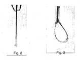
- ionization and vaporization on such an electrodewill always begin and be dominant at locations of enhanced field strength, leading to uneven cutting and excessive damage in front of these singular points, as shown in Fig. 2 .
- a ring electrodeshown in Fig. 3 . Its field is uniform except for the points of deviation from perfectly round shape, such as where the ring electrode contacts with a holder. Fortunately, these regions of deviation can be kept away from tissue during surgery.
- the threshold voltage on " such an electrodeis set by the wire radius (equations 2 and 4) and thus is limited by the mechanical strength of the wire.
- a thin wireis very weak and flexible and is thus inapplicable to manipulation of tissue.
- wires thinner than 25 micronsare barely seen under a conventional surgical microscope, and this makes their use even more difficult.
- An additional problem with the application of thin wiresis that erosion of thin wires greatly limits their lifetime.
- Tissuecan be cut uniformly along an extensive cutting zone through the use of an electrosurgical cutting system that comprises an electrically conductive blade, insulators, and a source of pulsed electrical energy coupled to the blade.
- the bladehas a first blade surface, a second blade surface, and a blade thickness.
- the blade thicknessis the smallest local distance between the first blade surface and the second blade surface.
- First and second insulatorsare affixed to the first and second blade surfaces, respectively.
- the first blade surface and the second blade surfacecome together along a blade edge.
- the blade edgeis perfectly sharp, but in practice the blade edge will be somewhat rounded and it is this rounded region between the first and second blade surfaces that will be called the blade edge.
- the blade edgewill have an edge radius of curvature, which ideally will be small (thereby providing a sharp blade edge). In practice, the entire blade edge is unlikely to be used for cutting, but only a blade cutting portion, which is a predetermined length of the blade that is used for cutting biological tissue. Unlike the ring electrode discussed earlier, the use of a blade provides substantial mechanical strength while the use of a blade edge with a small edge radius of curvature can provide a substantially uniform enhanced electric field along its cutting zone.
- biological tissueis cut with the electrosurgical system with a sharp blade edge by manipulating the blade in a biological medium such that the sharp blade edge is in close proximity to the tissue to be cut.
- the approachthen involves applying at least one electrical pulse along the cutting zone of the blade edge that contacts the region of biological tissue to be cut.
- multiple electrical pulsesare applied to the sharp blade edge.
- the electrical pulsesare of sufficient strength to generate electric breakdown in the tissue that is in a close proximity to the sharp blade edge.
- the pulse durationis sufficiently long for the generation of a streamer and spark discharge but is sufficiently short to avoid the development of a high current arc discharge. In this case, whether the current was high would be with comparison to the current generated in the biological medium prior to the development of the arc.
- Tissuecan also be cut uniformly along an extensive cutting zone without the use of a blade as described above.
- biological tissue immersed in a liquid mediumcan be cut uniformly along a cutting zone of an electrode (not necessarily in the form of a blade) by first forming a uniform vapor cavity surrounding the cutting zone of the electrode. This can be accomplished through the tailoring of the electrical pulses applied to the electrode. After forming the uniform vapor cavity, this approach involves ionizing the vapor in the cavity. This results in a plasma-mediated discharge into the biological tissue inside the vapor cavity.
- a burst of pulsed electrical energyis applied to a blade having a blade edge with a relatively small edge radius of curvature.
- the number of pulses and the energy of each pulseis chosen such that liquid adjacent to the blade cutting portion of the blade edge prior to application of the burst of pulses is, at some time prior to completion of the burst of pulses, vaporized along the entire blade cutting portion of the blade edge.
- the electrical pulseshave alternating polarity. Alternating the polarity of the pulses greatly reduces the electroporation-related tissue damage away from the immediate vicinity of the cut.
- a blade of an electrically conductive materialis provided.
- the bladewill have a first blade surface and an opposing second blade surface.
- the first and second blade surfacesjoin at a blade edge.
- the first and second blade surfaces in a predetermined cutting zone near the blade edgeare tapered to form a tapering region, which is the region in which the first and second blade surfaces converge towards each other.
- the bladeis coated with a thin layer of insulator to form a coated blade.
- the coated bladeis immersed in a conductive medium.
- a source of pulsed electrical energyis coupled to the blade. Pulsed electrical energy is then applied to the blade until the thin layer of insulator is removed from the vicinity of the blade edge. Preferably the thin layer of insulator is removed over the entire tapering region.
- Fig. 4Adepicts an electrically conductive blade 100 having a first blade surface 110, a second blade surface 120, and a blade edge 130.
- the blade edge 130is somewhat rounded, the edge radius of curvature 140 being shown in the magnified view of Fig. 4 B.
- a first insulator 210is affixed to the first blade surface 110.
- a second insulator 220is affixed to the second blade surface 120.
- a source of pulsed electrical energy 300is coupled to the blade 100.
- the other terminal from the source of pulsed electrical energy 300is connected to a return electrode (not shown) immersed in the medium in which the blade 100 is inserted.
- the blade thicknessis the smallest distance between the first blade surface 110 and the second blade surface 120. In preferred embodiments, in the region adjacent the blade edge 130, the blade thickness is reduced approximately linearly as the first 110 and second 120 blade surfaces approach the blade edge 130.
- a blade tapering angle 150is the angle of convergence of the first 110 and second 120 blade surfaces as the blade edge 130 is approached. In preferred embodiments the blade tapering angle 150 is less than 45 degrees; in more preferred embodiments the blade tapering angle 150 is less than 30 degrees; and in the most preferred embodiments the blade tapering angle 150 is less than 15 degrees.
- first 210 and second 220 insulatorsextend completely to the blade edge 130
- first 210 and second 220 insulatorsterminate prior to the blade edge 130. This leaves an exposed portion of the blade 100.
- the exposed portion of the blade 100extends through all or most of the tapering region. The exposed portion of the blade 100 between the blade edge 130 and the first 210 and second 220 insulators does not significantly reduce the electric field on the blade edge 130 , but it decreases electrical impedance and thus increases the energy deposited into the biological tissue.
- first 210 and second 220 insulatorssome distance from the blade edge 130 keeps the insulators away from stresses induced by pulsed heating, vaporization and ionization. The extra distance also provides for some depth of metal for etching, which helps to increase the productive lifetime of the blade 100.
- Figs. 4C-Eshow a variety of planform, or in-plane, shapes that are useful in various embodiments of the blade 100 .
- the blade 100takes the form of a disk, and hence the blade 100 is sometimes denoted a disk electrode.
- the first and second blade surfaceseach has a radius of curvature in a plane perpendicular to the thickness, (sometimes known as the planar or in-plane radius of curvature 160 ) that is constant at all points on the blade 100 .
- the blade 100has an elliptical planform and the planar radius of curvature 160 (shown only schematically) varies considerably along the blade edge.
- the planform shown in Fig. 4Eis more general.
- the planar radius of curvature 160is much larger than the edge radius of curvature, at least in the blade cutting portion 170 .
- the blade cutting portion 170is a predetermined length of the blade 100 that is used for cutting biological tissue.
- the blade cutting portion 170has been chosen to coincide with the heavier line.
- the planar radius of curvature 160 in the blade cutting portion 170is at least 5, 10, 25, 50, 100, or even thousands of times greater than the edge radius of curvature. Regions where the planar radius of curvature 160 is much greater than the edge radius of curvature are considered to have a sharp blade edge. Having an extensive blade cutting portion 170 with a sharp blade edge facilitates uniform (or nearly uniform) enhancement of the electric field along the blade edge of the blade cutting portion 170.
- the electric field around a sharp exposed blade edgeis similar to that on a ring electrode, but the radius of curvature is not limited by mechanical strength anymore.
- the blade edgecan be sharpened much more because the mechanical strength for this structure is provided by the blade.
- visibility of this electrodeis no longer a problem - the macroscopic blade can be easily observed while its very sharp blade edge might not be well resolved in a conventional surgical microscope.
- the blade edge of such an electrodecan have an edge radius of curvature much smaller than 10 microns. This will strongly reduce the threshold voltage and energy, as well as the penetration depth of the field into the tissue, which in turn leads to a cleaner cut with a smaller zone of damaged tissue.
- the distribution of electric field along a 5 ⁇ m-thick blade edge on a disk electrodeis shown in Fig. 1 .
- the electric field on the blade edgeremains uniform, or nearly uniform, even if the planar shape of the electrode is not exactly round.
- the electric fieldremains uniform as long as the planar radius of curvature of the blade remains much larger than the edge radius of curvature of the blade edge and the edge radius of curvature is uniform or nearly so.
- a disk electrodecan be deformed into an ellipse or other shape of a blade.
- Such a blade electrodewill preserve a substantially uniform distribution of electric field along the blade edge and can be used for uniform dissection or ablation of tissue with any part on its perimeter. Examples of uniform formation of vapor bubbles and ionization along the blade edge of such an electrode are shown in Figs. 5A-C.
- the field enhancement at the blade edge of the blade electrodedepends on the blade tapering angle.
- a lower blade tapering anglefacilitates access to tissue and penetration into it.
- the threshold energyis reduced by a factor of 2 when the tapering angle changes from 30° to 0°.
- the blade tapering angleshould preferably be less than 45°, and more preferably less than 30°, and most preferably less than 15°.
- the blade electrodeshould be made of a material capable of withstanding high temperatures.
- the materialshould be hard enough to provide sufficient rigidity when used as a thin blade.
- itshould be made of a material with low thermal conductivity. Materials fitting all these characteristics are for example, Tungsten, and more preferably Titanium since its thermal conductivity is 8 times lower.
- Electroporationis a direct effect of high electric fields on the membranes of cells. Electroporation results in an increase of the cell permeability and may lead to cell injury or death. To reduce this effect a voltage-balanced or a charge-balanced pair of pulses of opposite polarity instead of a single pulse of one polarity can be applied. This change leads to significant reduction in tissue damage.
- a microblade of 0.2-0.6 mm in length with insulated flat sides and exposed sharp edgesserves as an electrode using bi-phasic charge-balanced waveforms with pulse duration varying from 0.1 to 5 ⁇ s.
- Retinal dissectionhas been performed with complete and partial vitrectomy on excised pig eyes and in-vivo rabbit eyes. Results were analyzed clinically and histologically.
- the instrumentcan be used as a vitreoretinal pick to elevate and expose membranes.
- a train of charge-balanced pulses of alternating polaritycan create uniform cutting along the edge of the blade without generation of visible gas in vitreous or fluid medium. Smooth cutting without turbulent flow or other mechanical interference occurs when operating at repetition rates around 100 Hz. Histology and propidium iodide staining of live tissue demonstrate that the collateral damage zone extends 40-80 um from the edge. With different waveforms the blade electrode can also coagulate.
- a symmetric AC waveform(voltage-balanced rather that charge-balanced) can be applied, which results in a damage zone less than 40 ⁇ m.
- the energyshould be delivered in a burst of pulses in such a way that evaporation of the liquid, leading to vapor bubble growth, first occurs in the areas of high electric field. Providing that the electric field is not sufficiently strong for ionization inside the vapor bubble, the vapor bubble will isolate that part of electrode from the conductive fluid. Hence, evaporation will begin in the surrounding areas having a somewhat weaker electric field. This process should continue until the last area of the electrode is covered by the vapor cavity before the first bubble collapses exposing the electrode in that area.
- This requirementsets the amplitude and optimal duration of the pulse or burst of pulses.
- the size of individual bubbles and the number of themcan be set by choosing the energy of each pulse in the burst and by number of pulses.
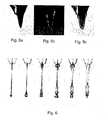
- An example of such process producing uniform vapor cavity along an electrode with a non-uniform electric fieldis shown in the sequence of photos of Fig. 6 .
- the wire diameteris 25 microns and the wire length is 1 mm.
- a single burst of pulsesis applied to the wire, having a burst duration of 30 ⁇ s, and containing pulses (or minipulses) having a duration of 2.5 ⁇ s separated by a pulse interval of 2.5 ⁇ s.
- the pulse voltageis 360 V.
- the lifetime of the bubbleextends to infinity.
- the amount of vapor inside the cavitydepends on the dynamics of the cavity formation. If the bubble is formed as a result of a very fast (as compared to lifetime of the cavitation bubble, which is typically above 10 microseconds) explosion the cavity quickly becomes very cold and is virtually empty. If the bubble is formed by slow (above 10 microseconds) heating and vaporization, the vapor pressure inside will be higher and closer to ambient pressure.
- the duration of a burst of pulsesis preferably less than 10 ms, and can be less than 1 ms or even less than 0.1 ms, to reduce thermal damage to tissue being cut.
- the duration of pulses within a burstis preferably between 10 ns and 10 ⁇ s.
- adjacent pulses within a burst of pulseshave opposite polarity to reduce electroporation damage to, tissue.
- burstsare repetitively applied to the electrode such that successive bursts are separated by a burst interval of 1 ms or more.
- Figs. 7A-Cillustrate the start of electric discharge in a saline solution.
- the electrodeis a metal anode
- glassserves as an insulator
- the saline solutionis the liquid conductive medium
- a cathodeis immersed in the saline solution.
- Fig. 7Ashows the early formation of a vapor cavity in the saline solution.
- R 1is the resistance from an equipotential through point A to an equipotential through point B.
- R 2is the electrical resistance from the equipotential through point B to the cathode.
- R 2is typically much larger than R 1 , because not all of the anode is blocked by the vapor cavity. Thus, only a small fraction of the anode potential U (i.e., U R 1 /(R 1 +R 2 )) is present across the vapor cavity. In other words, the saline alongside the vapor cavity acts as a shunt resistor and thus the voltage drop across a vapor cavity is small until the vapor cavity completely covers the electrode.
- Fig. 7Bshows the vapor cavity at a later time in which it has grown to completely encompass the anode. Therefore the entire anode potential U is present across the vapor cavity, since current flow is blocked by the vapor cavity.
- Fig. 7Cshows ignition of an electric discharge 500 inside the cavity.
- the electrical potential different from A to Bexceeds the ionization threshold for the vapor cavity, the gas in the vapor cavity ionizes and current flows from the electrode, across the vapor cavity to the conductive liquid medium.
- the anode voltage Uis selected so that U is greater than the ionization threshold for the complete vapor cavity of Fig.
- the bubbles formed during this processgrow slowly, on the order of tens of microseconds, so that the maximum velocity associated with bubble growth is below about 10 m/s.
- Such slow growing bubblesare not as mechanically damaging as cavitation bubbles that have maximum velocities on the order of 100 m/s.
- small bubblesare preferred to further minimize mechanical damage at the boundary of the surgical cut.
- ionizationbegins and the discharge is predominant in front of tissue, i.e. in the areas where tissue is located closer to electrode than the boundary of the vapor cavity in liquid. Therefore, using this approach, the uniformity of the original electric field is not critical because the tissue will only be exposed to electric current after ionization of the vapor cavity, which will occur substantially uniformly along the vapor cavity.
- a burst of pulsesshould consist of pairs of symmetric bi-phasic or charge-balanced pulses, as described above.
- a burst of pulsescan be applied for vaporization of liquid along a sharp edge of a disk or blade electrode. If a sharp edge is produced along a blade that has a singular point (small planar radius of curvature) at its apex then ordinarily, the advantage of an enhanced electric field associated with the sharp blade edge is tempered by the nonuniformity of the field caused by the apex. However, by using the approach described above for vaporizing the region along the electrode prior to ionizing the vapor bubble the problem of the field non-uniformity can be fixed.
- the sharp blade edgeprovides field enhancement that leads to a smaller damage zone and lower threshold energy and is mechanically supported by the thicker part of the insulated blade.
- the apex with an associated strong fieldcan be neutralized by application of a burst of pulses of optimal duration.
- Figs. 8A-Cshow the use of a pulsed electric field to first generate a vapor bubble around a sharp blade edge and then produce an electric discharge from the blade to the targeted biological tissue by ionization of the vapor.
- Fig. 8Ashows the blade electrode before the vapor cavity is formed.
- Fig. 8Bshows a vapor cavity forming over the portion of the blade electrode not covered by the insulator.
- the electrical potentialis high enough, an electric discharge occurs between the blade electrode and the tissue as shown in Fig. 8C .
- the dischargeis concentrated in the region of smallest separation (least resistance) between the electrode and the tissue.
- a thin electrodeis rapidly etched during use, especially in the evaporation mode.
- a sharp blade edge of a blade electrodealso is rapidly etched in use. Rounding the edge by etching, i.e., increasing the edge radius of curvature, leads to an increase in the threshold voltage and pulse energy, which in turn, will increase the extent of the collateral damage zone. To prevent this effect a "controlled etching" leading to self-sharpening can be implemented.
- Etchingis most efficient inside the zone of evaporation (i.e., the vapor bubble). Therefore, the region of most efficient etching can be determined by parameters of the driving waveform, which determine the size of the vapor bubble. Self-sharpening can be achieved by sizing the vapor bubble to include the tapering region near the blade edge. In such a case, efficient etching occurs over the entire tapering region, and the blade edge can be maintained with an approximately constant edge radius of curvature. Optimal width of the etching zone is determined by'the thickness of the blade and the desirable tapering angle.
- the tapering regionextends a distance r 0 + (D/2 -r 0 )/tan( ⁇ /2) inward from the end of the blade edge.
- the vapor bubbleshould extend at least this far inward from the end of the blade edge.
- blade 100can be slidably mounted between insulators 210 and 220 such that erosion of blade 100 during operation can be compensated by extending a fresh section of blade 100 from between insulators 210 and 220.
- the bladeis milled to achieve an appropriate blade tapering angle either before, or immediately after the blade surfaces are covered with thin layers of insulators.
- the bladeis immersed into a conductive medium and electrical pulses are applied with waveform parameters similar or identical to those appropriate for electrosurgery.
- the electrical discharge at discontinuitieswill break and remove the insulator from the active surfaces of the electrode, but in other areas the insulator will remain intact.
- Fig. 9shows the etching of a Tungsten blade by discharges at pulse settings that would be appropriate for surgical cutting. The edge remains sharp as the blade gets shoter.
Landscapes
- Engineering & Computer Science (AREA)
- Health & Medical Sciences (AREA)
- Plasma & Fusion (AREA)
- Physics & Mathematics (AREA)
- Life Sciences & Earth Sciences (AREA)
- Surgery (AREA)
- Medical Informatics (AREA)
- Otolaryngology (AREA)
- Spectroscopy & Molecular Physics (AREA)
- Biomedical Technology (AREA)
- Heart & Thoracic Surgery (AREA)
- Nuclear Medicine, Radiotherapy & Molecular Imaging (AREA)
- Molecular Biology (AREA)
- Animal Behavior & Ethology (AREA)
- General Health & Medical Sciences (AREA)
- Public Health (AREA)
- Veterinary Medicine (AREA)
- Surgical Instruments (AREA)
- Electrotherapy Devices (AREA)
Description
- The present disclosure relates generally to an electro-surgical device, and in particular, to the design of efficient electro-surgical probes and waveforms for pulsed plasma-mediated cutting, fragmentation, and evaporation of biological tissue in fluid media.
- Plasma-mediated cutting of soft biological tissue in conductive liquid media with sub-microsecond pulses of high voltage is described in the patent of
Palanker [U. S. Patent Number 6,135,998 ]. Dissection of tissue based on explosive vaporization by short (under few microseconds) pulses of high voltage is described in the patent ofLewis et al [U. S. Patent Number 6,352,535 ]. In these applications an inlaid cylindrical electrode (i.e. a wire embedded into a thick insulator and exposed at its end) is applied to ionize, evaporate and fragment tissue in proximity of electrode using dielectric breakdown or vaporization of water induced by a high electric field. An inlaid cylindrical electrode cannot penetrate into tissue and thus can only produce shallow cuts on its surface. Due to the pulsed regime of application, this device produces a series of perforations in tissue, which often do not merge into a continuous cut. In addition, cavitation bubbles accompanying each pulse create substantial collateral damage in tissue during their growth and collapse phases [Effect of the Probe Geometry on Dynamics of Cavitation, D. Palanker, A. Vankov, and J. Miller, Laser-Tissue Interactions XIII, vol. 4617 SPIE (2002)]. The size of such a damage zone typically far exceeds the size of the S02-314/PCT electrode and the corresponding zone of initial energy deposition [Effect of the Probe Geometry on Dynamics of Cavitation, D. Palanker, A. Vankov, and J. Miller, Laser-Tissue Interactions XIII, vol. 4617 SPIE (2002)]. Reduction in pulse energy helps to reduce the mechanical damage, but also leads to decreased cutting depth. - A second mechanism of electrosurgical ablation is vaporization of tissue in the proximity of the probe by overheating a conductive medium with either a continuous radio frequency waveform or with sub-millisecond long bursts of pulses. This mechanism is universally applicable to soft and hard biological tissue ranging from membranes and retina to skin and cartilage. In such regimes wire electrodes are typically used, although the use of a device that could provide a uniform electric field along its length would be preferable.
- Without considering end effects, the electric field in a conductive liquid at distance r from a cylindrical electrode with potential U and radius ro much smaller than its length L is:

assuming that the return electrode is much larger and positioned at infinity. The threshold electric field required for dielectric breakdown in water is on the order of 105-106 V/cm [Jones, H. M. & Kunhardt, E. E. Development of Pulsed Dielectric Breakdown In Liquids. Journal of Physics D-Applied Physics 28, 178-188 (1995);
Jones, H. M. & Kunhardt, E. E. Pulsed Dielectric Breakdown of Pressurized Water and Salt Solutions. Journal of Applied Physics 77, 795-805 (1995)]. Such a threshold electric field Eth can be achieved with electric pulses of several kV on a wire electrode with a diameter of several tens of micrometers. The threshold voltage required for ionization of a surface layer of water is:'
- The corresponding threshold energy is:

- Evaporation of water in the proximity of an electrode begins when the temperature is elevated above 100 °C. The threshold voltage required for vaporization of a surface layer is:

where T is a pulse duration, y is the electrical conductivity of the liquid, p is the liquid density, c is the liquid heat capacity, and ΔT is the temperature change. The corresponding threshold energy is:
- Lower threshold voltage and energy, as well as better localization of energy deposition can be achieved by decreasing the radius of electrode ro, as follows from equations 1-5. However, this approach is limited by the mechanical strength of the thin wire and its visibility. In addition, the problem of non-uniform distribution of electric field along the electrode, and particularly, enhancement at the apex remains.
- This enhancement is illustrated in
Fig. 1A , which shows the electric field surrounding a wire electrode. The field is stronger at the apex (i.e., at distance = 0) and is weaker in its cylindrical portion. Thus ionization and vaporization on such an electrode will always begin and be dominant at locations of enhanced field strength, leading to uneven cutting and excessive damage in front of these singular points, as shown inFig. 2 . - One geometry that provides uniform enhancement of an electric field is a ring electrode shown in
Fig. 3 . Its field is uniform except for the points of deviation from perfectly round shape, such as where the ring electrode contacts with a holder. Fortunately, these regions of deviation can be kept away from tissue during surgery. The threshold voltage on " such an electrode is set by the wire radius (equations 2 and 4) and thus is limited by the mechanical strength of the wire. For example, a thin wire is very weak and flexible and is thus inapplicable to manipulation of tissue. In addition, wires thinner than 25 microns are barely seen under a conventional surgical microscope, and this makes their use even more difficult. An additional problem with the application of thin wires is that erosion of thin wires greatly limits their lifetime. - Below we describe probe geometry and pulse waveform structures that provide solutions to these and other problems.
- Also are known in this field, devices described in Patent applications
WO 99/32042 WO 99/40858 WO 00/54683 - The invention is set out in the appended claims. The embodiments examples or aspects of the present disclosure that do not fall within the scope of said claims an provided for illustrative purposes only and do not form part of the present invention. What is desired is a penetrating electrode that can cut tissue uniformly along an extensive cutting zone, rather than just with its apex. As will be shown below, this objective can be achieved through geometric tailoring of the electrode, careful design of the electrical pulses applied to the electrode, or a combination of these approaches.
- Tissue can be cut uniformly along an extensive cutting zone through the use of an electrosurgical cutting system that comprises an electrically conductive blade, insulators, and a source of pulsed electrical energy coupled to the blade. In particular, the blade has a first blade surface, a second blade surface, and a blade thickness. The blade thickness is the smallest local distance between the first blade surface and the second blade surface. First and second insulators are affixed to the first and second blade surfaces, respectively. The first blade surface and the second blade surface come together along a blade edge. Ideally, the blade edge is perfectly sharp, but in practice the blade edge will be somewhat rounded and it is this rounded region between the first and second blade surfaces that will be called the blade edge. The blade edge will have an edge radius of curvature, which ideally will be small (thereby providing a sharp blade edge). In practice, the entire blade edge is unlikely to be used for cutting, but only a blade cutting portion, which is a predetermined length of the blade that is used for cutting biological tissue. Unlike the ring electrode discussed earlier, the use of a blade provides substantial mechanical strength while the use of a blade edge with a small edge radius of curvature can provide a substantially uniform enhanced electric field along its cutting zone.
- In preferred embodiments, biological tissue is cut with the electrosurgical system with a sharp blade edge by manipulating the blade in a biological medium such that the sharp blade edge is in close proximity to the tissue to be cut. The approach then involves applying at least one electrical pulse along the cutting zone of the blade edge that contacts the region of biological tissue to be cut. In preferred embodiments, multiple electrical pulses are applied to the sharp blade edge. The electrical pulses are of sufficient strength to generate electric breakdown in the tissue that is in a close proximity to the sharp blade edge. The pulse duration is sufficiently long for the generation of a streamer and spark discharge but is sufficiently short to avoid the development of a high current arc discharge. In this case, whether the current was high would be with comparison to the current generated in the biological medium prior to the development of the arc.
- Tissue can also be cut uniformly along an extensive cutting zone without the use of a blade as described above. In this approach, biological tissue immersed in a liquid medium can be cut uniformly along a cutting zone of an electrode (not necessarily in the form of a blade) by first forming a uniform vapor cavity surrounding the cutting zone of the electrode. This can be accomplished through the tailoring of the electrical pulses applied to the electrode. After forming the uniform vapor cavity, this approach involves ionizing the vapor in the cavity. This results in a plasma-mediated discharge into the biological tissue inside the vapor cavity.
- These two approaches can be combined to form very effective methods for cutting biological tissue. In the combined approach for cutting biological tissue, a burst of pulsed electrical energy is applied to a blade having a blade edge with a relatively small edge radius of curvature. The number of pulses and the energy of each pulse is chosen such that liquid adjacent to the blade cutting portion of the blade edge prior to application of the burst of pulses is, at some time prior to completion of the burst of pulses, vaporized along the entire blade cutting portion of the blade edge. With the combined approach, nonuniformities in the electric field along the blade edge are effectively smoothed out.
- In the most preferred embodiments of these methods, the electrical pulses have alternating polarity. Alternating the polarity of the pulses greatly reduces the electroporation-related tissue damage away from the immediate vicinity of the cut.
- An electrosurgical cutting system as described above can be readily fabricated. A blade of an electrically conductive material is provided. The blade will have a first blade surface and an opposing second blade surface. The first and second blade surfaces join at a blade edge. In preferred embodiments, the first and second blade surfaces in a predetermined cutting zone near the blade edge are tapered to form a tapering region, which is the region in which the first and second blade surfaces converge towards each other. The blade is coated with a thin layer of insulator to form a coated blade. The coated blade is immersed in a conductive medium. A source of pulsed electrical energy is coupled to the blade. Pulsed electrical energy is then applied to the blade until the thin layer of insulator is removed from the vicinity of the blade edge. Preferably the thin layer of insulator is removed over the entire tapering region.
Fig. 1A illustrates the electric field along wire electrodes of 10, 25 and 50 microns in diameter (410, 440, and430 respectively) and 530 microns in length, and along the 5 µm-thick edge of a disk electrode of 400 µm in diameter(420). The exposed zone of the disk electrode is 50 µm from the edge. The electrode potential is 600 V in all cases.Fig. 1B illustrates the edge of the disk electrode used inFig. 1A .Fig. 2 shows the formation of a cavitation (vapor) cavity at the apex of the wire electrode in saline several microseconds after beginning of electrical pulse. This effect demonstrates that electric field at the apex is much higher than in other parts of the wire electrode.Fig. 3 shows a 10 µm-thick wire loop electrode in saline with cavitation bubbles forming simultaneously along all its length. This effect demonstrates the uniformity in distribution of the electric field along its surface.Fig. 4A shows an electrically conductive blade with insulators adjacent to the blade surfaces. The blade surfaces join at a blade edge.Fig 4B shows a magnified view of the region around the blade edge. The blade tapering angle and the edge radius of curvature are shown.Fig. 4C shows a blade having a circular planform.Fig. 4D shows a blade with an elliptical planform.Fig. 4E shows a blade having a planform of more general shape, with the heavier line weight corresponding to the blade cutting portion.Fig: 5A shows a blade electrode with insulated flat sides and an exposed sharp edge and tapering region on a perimeter.Fig. 5B shows light emission by plasma forming on the exposed portion after a 200 ns pulse of 3.4 kV in saline.Fig. 5C shows vapor (cavitation) bubbles uniformly covering the exposed portion 5 µs after the pulse.Fig. 6 shows a sequence of photographs demonstrating formation of a uniform cavity along an electrode with a non-uniform electric field using a sequence (burst) of pulses. For complete coverage of the electrode the duration of the burst should not exceed the lifetime of the first bubbleFigs. 7A-C show a sequence illustrating the initiation of an electric arc.Figs. 8A-C shown an electrode as a blade edge and biological tissue immersed in saline.Fig. 8A shows the electrode before the vapor cavity formation.Fig. 8B shows a vapor cavity forming over the portion of the electrode not covered by the insulator. When the electrical potential is high enough, an electric discharge occurs between the electrode and the tissue as shown inFig. 8C . As shown inFig. 8C , the discharge is concentrated in the region of smallest separation (least resistance) between the electrode and the tissue.Fig. 9 shows that etching of a 15 µm-thick Tungsten blade by electric discharges at surgical settings leaves the blade edge sharp as it shortens.- Referring now to the drawings, where similar elements are numbered the same,
Fig. 4A depicts an electricallyconductive blade 100 having afirst blade surface 110, asecond blade surface 120, and ablade edge 130. In practice, theblade edge 130 is somewhat rounded, the edge radius ofcurvature 140 being shown in the magnified view ofFig. 4 B. Afirst insulator 210 is affixed to thefirst blade surface 110. Similarly, asecond insulator 220 is affixed to thesecond blade surface 120. To complete an electrosurgical cutting system, a source of pulsedelectrical energy 300 is coupled to theblade 100. The other terminal from the source of pulsedelectrical energy 300 is connected to a return electrode (not shown) immersed in the medium in which theblade 100 is inserted. - At any position on the
blade 100, the blade thickness is the smallest distance between thefirst blade surface 110 and thesecond blade surface 120. In preferred embodiments, in the region adjacent theblade edge 130, the blade thickness is reduced approximately linearly as the first110 and second120 blade surfaces approach theblade edge 130. Ablade tapering angle 150 is the angle of convergence of the first110 and second120 blade surfaces as theblade edge 130 is approached. In preferred embodiments theblade tapering angle 150 is less than 45 degrees; in more preferred embodiments theblade tapering angle 150 is less than 30 degrees; and in the most preferred embodiments theblade tapering angle 150 is less than 15 degrees. - Although in some embodiments the first210 and second220 insulators extend completely to the
blade edge 130, in preferred embodiments the first210 and second220 insulators terminate prior to theblade edge 130. This leaves an exposed portion of theblade 100. As shown inFigs. 4A and4B , in the most preferred embodiments the exposed portion of theblade 100 extends through all or most of the tapering region. The exposed portion of theblade 100 between theblade edge 130 and the first210 and second220 insulators does not significantly reduce the electric field on theblade edge 130, but it decreases electrical impedance and thus increases the energy deposited into the biological tissue. Ending the first210 and second220 insulators some distance from theblade edge 130 keeps the insulators away from stresses induced by pulsed heating, vaporization and ionization. The extra distance also provides for some depth of metal for etching, which helps to increase the productive lifetime of theblade 100. Figs. 4C-E show a variety of planform, or in-plane, shapes that are useful in various embodiments of theblade 100. In a canonical embodiment shown inFig. 4C , theblade 100 takes the form of a disk, and hence theblade 100 is sometimes denoted a disk electrode. In such ablade 100, the first and second blade surfaces each has a radius of curvature in a plane perpendicular to the thickness, (sometimes known as the planar or in-plane radius of curvature160) that is constant at all points on theblade 100. In another canonical embodiment shown inFig.4D , theblade 100 has an elliptical planform and the planar radius of curvature160 (shown only schematically) varies considerably along the blade edge.- The planform shown in
Fig. 4E is more general. In preferred embodiments the planar radius ofcurvature 160 is much larger than the edge radius of curvature, at least in theblade cutting portion 170. Theblade cutting portion 170 is a predetermined length of theblade 100 that is used for cutting biological tissue. InFig. 4E , theblade cutting portion 170 has been chosen to coincide with the heavier line. In preferred embodiments the planar radius ofcurvature 160 in theblade cutting portion 170 is at least 5, 10, 25, 50, 100, or even thousands of times greater than the edge radius of curvature. Regions where the planar radius ofcurvature 160 is much greater than the edge radius of curvature are considered to have a sharp blade edge. Having an extensiveblade cutting portion 170 with a sharp blade edge facilitates uniform (or nearly uniform) enhancement of the electric field along the blade edge of theblade cutting portion 170. - The electric field around a sharp exposed blade edge is similar to that on a ring electrode, but the radius of curvature is not limited by mechanical strength anymore. The blade edge can be sharpened much more because the mechanical strength for this structure is provided by the blade. In addition, visibility of this electrode is no longer a problem - the macroscopic blade can be easily observed while its very sharp blade edge might not be well resolved in a conventional surgical microscope. Thus the blade edge of such an electrode can have an edge radius of curvature much smaller than 10 microns. This will strongly reduce the threshold voltage and energy, as well as the penetration depth of the field into the tissue, which in turn leads to a cleaner cut with a smaller zone of damaged tissue. The distribution of electric field along a 5 µm-thick blade edge on a disk electrode is shown in
Fig. 1 . - The small radius of curvature and low threshold energy make the interaction zone with tissue very shallow, thus fast cutting can be achieved at sufficiently high pulse repetition rates. Cutting tissue by small steps at high repetition rate results in a very smooth action leaving very clean edges of the lesion. For successful insertion of such thin electrode into tissue the layer of insulator on its flat sides (first and second blade surfaces) should be thin - comparable or thinner than the edge radius of curvature.
- Providing the blade edge is sharp with nearly uniform edge radius of curvature, the electric field on the blade edge remains uniform, or nearly uniform, even if the planar shape of the electrode is not exactly round. The electric field remains uniform as long as the planar radius of curvature of the blade remains much larger than the edge radius of curvature of the blade edge and the edge radius of curvature is uniform or nearly so. Thus a disk electrode can be deformed into an ellipse or other shape of a blade. Such a blade electrode will preserve a substantially uniform distribution of electric field along the blade edge and can be used for uniform dissection or ablation of tissue with any part on its perimeter. Examples of uniform formation of vapor bubbles and ionization along the blade edge of such an electrode are shown in
Figs. 5A-C. - The field enhancement at the blade edge of the blade electrode depends on the blade tapering angle. The lower the tapering angle, the more effective is the enhancement of the electric field. In addition, a lower blade tapering angle facilitates access to tissue and penetration into it. The threshold energy is reduced by a factor of 2 when the tapering angle changes from 30° to 0°. Thus, for maximal enhancement of the field, as well as for the most convenient access to tissue and penetration into it, the blade tapering angle should preferably be less than 45°, and more preferably less than 30°, and most preferably less than 15°.
- To reduce the rate of etching of the blade by hot plasma, the blade electrode should be made of a material capable of withstanding high temperatures. In addition, the material should be hard enough to provide sufficient rigidity when used as a thin blade. Additionally, to reduce the outflow of heat from the treated area via the blade electrode, it should be made of a material with low thermal conductivity. Materials fitting all these characteristics are for example, Tungsten, and more preferably Titanium since its thermal conductivity is 8 times lower.
- One of the mechanisms of tissue damage in electrosurgery is electroporation. This is a direct effect of high electric fields on the membranes of cells. Electroporation results in an increase of the cell permeability and may lead to cell injury or death. To reduce this effect a voltage-balanced or a charge-balanced pair of pulses of opposite polarity instead of a single pulse of one polarity can be applied. This change leads to significant reduction in tissue damage. For example, application of a single pulse of 200 ns duration and 4 kV in amplitude produces electroporation-related damage on the order of 260 µm, while charge-balanced bi-phasic pulses applied to the same electrode at the same amplitude produces only 90 µm of electroporation-related damage (measured on chorioallantoic membrane of chicken embryo using Propidium Iodide staining technique). In addition to its biological advantage, alternating the polarity of the pulses also decreases the erosion rate of the electrode.
- In a preferred embodiment, a microblade of 0.2-0.6 mm in length with insulated flat sides and exposed sharp edges serves as an electrode using bi-phasic charge-balanced waveforms with pulse duration varying from 0.1 to 5 µs. Retinal dissection has been performed with complete and partial vitrectomy on excised pig eyes and in-vivo rabbit eyes. Results were analyzed clinically and histologically. When no energy is applied the instrument can be used as a vitreoretinal pick to elevate and expose membranes. A train of charge-balanced pulses of alternating polarity can create uniform cutting along the edge of the blade without generation of visible gas in vitreous or fluid medium. Smooth cutting without turbulent flow or other mechanical interference occurs when operating at repetition rates around 100 Hz. Histology and propidium iodide staining of live tissue demonstrate that the collateral damage zone extends 40-80 um from the edge. With different waveforms the blade electrode can also coagulate.
- To reduce electroporation, a symmetric AC waveform, (voltage-balanced rather that charge-balanced) can be applied, which results in a damage zone less than 40 µm.
- Uneven distribution of the electric field along the electrode affects its performance not only in the regime of dielectric breakdown in liquid, but also in the regime of evaporation of water. This effect can be neutralized using specially designed pulse waveforms. The energy should be delivered in a burst of pulses in such a way that evaporation of the liquid, leading to vapor bubble growth, first occurs in the areas of high electric field. Providing that the electric field is not sufficiently strong for ionization inside the vapor bubble, the vapor bubble will isolate that part of electrode from the conductive fluid. Hence, evaporation will begin in the surrounding areas having a somewhat weaker electric field. This process should continue until the last area of the electrode is covered by the vapor cavity before the first bubble collapses exposing the electrode in that area. This requirement sets the amplitude and optimal duration of the pulse or burst of pulses. The size of individual bubbles and the number of them can be set by choosing the energy of each pulse in the burst and by number of pulses. An example of such process producing uniform vapor cavity along an electrode with a non-uniform electric field is shown in the sequence of photos of
Fig. 6 . - In the example of
Fig. 6 , the wire diameter is 25 microns and the wire length is 1 mm. A single burst of pulses is applied to the wire, having a burst duration of 30 µs, and containing pulses (or minipulses) having a duration of 2.5 µs separated by a pulse interval of 2.5 µs. The pulse voltage is 360 V. - The lifetime of an empty spherical cavity of radius Ro in water (density p=1000 kg/m3) and under atmospheric pressure (Po=105 N/m2) is t=0.91Ro(ρ/Po)1/2. That means an empty bubble with
radius 100 µm will collapse in approximately 10 µs. If the bubble is not empty, i.e. if the vapor pressure inside is significant, the lifetime will increase. No simple estimates for the cavity lifetime is known, but as a first approximation P, which is a difference between the pressure outside and inside the bubble, can replace Po. Thus if the vapor pressure inside is 0.9 Po, then P=0.1 Po, and the lifetime t will increase by a factor of 101/2, approximately 3. As the vapor pressure inside the cavity approaches atmospheric pressure the lifetime of the bubble extends to infinity. The amount of vapor inside the cavity depends on the dynamics of the cavity formation. If the bubble is formed as a result of a very fast (as compared to lifetime of the cavitation bubble, which is typically above 10 microseconds) explosion the cavity quickly becomes very cold and is virtually empty. If the bubble is formed by slow (above 10 microseconds) heating and vaporization, the vapor pressure inside will be higher and closer to ambient pressure. These theoretical guidelines can be used to help design waveforms, but some experimentation is likely to be necessary to determine the best waveforms for any particular set of circumstances. - The duration of a burst of pulses is preferably less than 10 ms, and can be less than 1 ms or even less than 0.1 ms, to reduce thermal damage to tissue being cut. The duration of pulses within a burst is preferably between 10 ns and 10 µs. Preferably, adjacent pulses within a burst of pulses have opposite polarity to reduce electroporation damage to, tissue. Preferably, bursts are repetitively applied to the electrode such that successive bursts are separated by a burst interval of 1 ms or more.
- After the vapor cavity covers the entire electrode, with the proper level of the electric field, ionization of the vapor can occur.
Figs. 7A-C illustrate the start of electric discharge in a saline solution. InFigs. 7A-C , the electrode, is a metal anode, glass serves as an insulator, the saline solution is the liquid conductive medium, and a cathode is immersed in the saline solution.Fig. 7A shows the early formation of a vapor cavity in the saline solution. R1 is the resistance from an equipotential through point A to an equipotential through point B. R2 is the electrical resistance from the equipotential through point B to the cathode. R2 is typically much larger than R1, because not all of the anode is blocked by the vapor cavity. Thus, only a small fraction of the anode potential U (i.e., U R1/(R1+R2)) is present across the vapor cavity. In other words, the saline alongside the vapor cavity acts as a shunt resistor and thus the voltage drop across a vapor cavity is small until the vapor cavity completely covers the electrode. Fig. 7B shows the vapor cavity at a later time in which it has grown to completely encompass the anode. Therefore the entire anode potential U is present across the vapor cavity, since current flow is blocked by the vapor cavity.Fig. 7C shows ignition of anelectric discharge 500 inside the cavity. When the electrical potential different from A to B exceeds the ionization threshold for the vapor cavity, the gas in the vapor cavity ionizes and current flows from the electrode, across the vapor cavity to the conductive liquid medium. Preferably, the anode voltage U is selected so that U is greater than the ionization threshold for the complete vapor cavity ofFig. 7B , and U R1/(R1+R2) is less than the ionization threshold of the partial vapor cavity ofFig. 7A . Selection of the anode voltage according to this condition ensures that the partial vapor cavity ofFig. 7A does not break down until it has grown to completely cover the anode.- Ideally the bubbles formed during this process grow slowly, on the order of tens of microseconds, so that the maximum velocity associated with bubble growth is below about 10 m/s. Such slow growing bubbles are not as mechanically damaging as cavitation bubbles that have maximum velocities on the order of 100 m/s. In addition, small bubbles are preferred to further minimize mechanical damage at the boundary of the surgical cut.
- In applications that involve the cutting of biological tissue, ionization begins and the discharge is predominant in front of tissue, i.e. in the areas where tissue is located closer to electrode than the boundary of the vapor cavity in liquid. Therefore, using this approach, the uniformity of the original electric field is not critical because the tissue will only be exposed to electric current after ionization of the vapor cavity, which will occur substantially uniformly along the vapor cavity. For minimization of electroporation-related damage a burst of pulses should consist of pairs of symmetric bi-phasic or charge-balanced pulses, as described above.
- With high electric fields, when ionization of water begins before vaporization, or when vapor cavity is ionized immediately after its formation, the disconnect of electrode from liquid does not occur and thus this process of sequential creation of multiple vapor bubbles along the electrode will not work.
- A burst of pulses can be applied for vaporization of liquid along a sharp edge of a disk or blade electrode. If a sharp edge is produced along a blade that has a singular point (small planar radius of curvature) at its apex then ordinarily, the advantage of an enhanced electric field associated with the sharp blade edge is tempered by the nonuniformity of the field caused by the apex. However, by using the approach described above for vaporizing the region along the electrode prior to ionizing the vapor bubble the problem of the field non-uniformity can be fixed. The sharp blade edge provides field enhancement that leads to a smaller damage zone and lower threshold energy and is mechanically supported by the thicker part of the insulated blade. The apex with an associated strong field can be neutralized by application of a burst of pulses of optimal duration.
Figs. 8A-C show the use of a pulsed electric field to first generate a vapor bubble around a sharp blade edge and then produce an electric discharge from the blade to the targeted biological tissue by ionization of the vapor.Fig. 8A shows the blade electrode before the vapor cavity is formed.Fig. 8B shows a vapor cavity forming over the portion of the blade electrode not covered by the insulator. When the electrical potential is high enough, an electric discharge occurs between the blade electrode and the tissue as shown inFig. 8C . As shown inFig. 8C , the discharge is concentrated in the region of smallest separation (least resistance) between the electrode and the tissue.- A thin electrode is rapidly etched during use, especially in the evaporation mode. A sharp blade edge of a blade electrode also is rapidly etched in use. Rounding the edge by etching, i.e., increasing the edge radius of curvature, leads to an increase in the threshold voltage and pulse energy, which in turn, will increase the extent of the collateral damage zone. To prevent this effect a "controlled etching" leading to self-sharpening can be implemented.
- Etching is most efficient inside the zone of evaporation (i.e., the vapor bubble). Therefore, the region of most efficient etching can be determined by parameters of the driving waveform, which determine the size of the vapor bubble. Self-sharpening can be achieved by sizing the vapor bubble to include the tapering region near the blade edge. In such a case, efficient etching occurs over the entire tapering region, and the blade edge can be maintained with an approximately constant edge radius of curvature. Optimal width of the etching zone is determined by'the thickness of the blade and the desirable tapering angle. For a blade of thickness D outside of the tapering region, blade tapering angle α, and edge radius of curvature r0, the tapering region extends a distance r0 + (D/2 -r0)/tan(α/2) inward from the end of the blade edge. Ideally the vapor bubble should extend at least this far inward from the end of the blade edge. Such a self-sharpening regime keeps the electrode functional for a long time despite the erosion. Alternatively,
blade 100 can be slidably mounted betweeninsulators blade 100 during operation can be compensated by extending a fresh section ofblade 100 from betweeninsulators - Technology for fabrication of such a blade can be simplified by using the electrical discharge itself to remove the insulators from the blade surfaces near the blade edge. Preferably, the blade is milled to achieve an appropriate blade tapering angle either before, or immediately after the blade surfaces are covered with thin layers of insulators. The blade is immersed into a conductive medium and electrical pulses are applied with waveform parameters similar or identical to those appropriate for electrosurgery. The electrical discharge at discontinuities will break and remove the insulator from the active surfaces of the electrode, but in other areas the insulator will remain intact. As the blade edge is etched during use, the insulator in its proximity will be removed as well.
Fig. 9 shows the etching of a Tungsten blade by discharges at pulse settings that would be appropriate for surgical cutting. The edge remains sharp as the blade gets shoter.


Claims (23)
- An electrosurgical cutting system, comprising:an electrically conductive blade (100), said blade having a first surface (110), a second surface (120) opposite said first surface, and an edge (130) where said first and second surfaces meet, said edge having an edge radius of curvature (140), wherein a predetermined length of said edge is a cutting portion for cutting biological tissue; said cutting portion having an in-plane radius of curvature in a plane perpendicular to the thickness of the black (160) that is at least 10 times larger than said edge radius of curvature along the entire length of said cutting portion.a first insulator (210) on said first surface;a second insulator (220) on said second surface; anda source of pulsed electrical energy (300) electrically connected to said blade, and wherein said source of pulsed electrical energy provides pulses having a duration between 10 ns and 10 µs and is configured to apply a plurality of bursts of pulses separated by a burst interval greater than about 1 ms during which no pulse is present, the duration of the burst of pulses being 1 ms or less, whereby thermal damage to said biological tissue is reduced.
- The system of claim 1, wherein said edge radius of curvature (140) is less than about 25 microns.
- The system of claim 2, wherein said edge radius of curvature (140) is less than about 10 microns.
- The system of claim 3, wherein said edge radius of curvature (140) is less than about 5 microns.
- The system of claim 4, wherein said edge radius of curvature (140) is less than about 1 micron.
- The system of claim 1, wherein along said cutting portion said first (210) and second (220) insulators each have a thickness less than said edge radius of curvature (140).
- The system of claim 1, wherein along said cutting portion said thickness decreases approximately linearly, within a tapering region, as said first (110) and second (120) surfaces approach said edge thereby to define a blade tapering angle (150).
- The system of claim 7, wherein said blade tapering angle (150) is less than 45 degrees.
- The system of claim 8, wherein said blade tapering angle (150) is less than 30 degrees.
- The system of claim 9, wherein said blade tapering angle (150) is less than 15 degrees.
- The system of claim 7, wherein said pulses provided by said source (300) are sufficient to vaporize and ionize a liquid medium present along said cutting portion thereby to form a vapor cavity encompassing said tapering region.
- The system of claim 1, wherein said blade (100) comprises Tungsten or Titanium.
- The system of claim 1, wherein said source (300) of pulsed electrical energy provides pulsed electrical energy with each pulse having opposite electrical polarity to that of the previous pulse.
- The system of claim 1, wherein each of said bursts of pulses has a duration less than 0.1 ms.
- The system of claim 1, wherein an energy of each pulse is such that a liquid adjacent to said cutting portion prior to application of the burst of pulses is vaporized.
- The system of claim 15, wherein a total duration of said burst of pulses is between 5 µs and 500 µs.
- The system of claim 16, wherein said total duration is between 10 µs and 100 µs.
- The system of claim 15, wherein any two time-adjacent pulses in said burst of pulses have opposite electrical polarities.
- The system of claim 1, wherein:said cutting portion is at least 50 µm long; anda strength of an electric field caused by said pulsed electrical energy at said cutting portion varies by no more than 50% along the entire length of said cutting portion.
- The system of claim 1, wherein said pulses from said source (300) have a duration sufficiently long for generation of a streamer and spark discharge, and sufficiently short to avoid generation of a high current arc discharge.
- The system of claim 1, wherein said blade (100) is configured and wherein pulses from said source (300) have a voltage such that a vapor cavity formed in a liquid medium adjacent said blade does not ionize until said vapor cavity extends to said first (210) and second (220) insulators.
- The system of claim 1, wherein said blade and said first and second insulators are configured to be etched together during operation, whereby said edge radius of curvature remains substantially unchanged during operation.
- The system of claim 1, wherein said blade (100) is slidably mounted between said first (210) and second (220) insulators, whereby said blade (100) can be extended to compensate for erosion of said blade during operation.
Applications Claiming Priority (3)
| Application Number | Priority Date | Filing Date | Title |
|---|---|---|---|
| US44771503P | 2003-02-14 | 2003-02-14 | |
| US447715P | 2003-02-14 | ||
| PCT/US2004/004290WO2004073752A2 (en) | 2003-02-14 | 2004-02-13 | Electrosurgical system with uniformly enhanced electric field and minimal collateral damage |
Publications (3)
| Publication Number | Publication Date |
|---|---|
| EP1603474A2 EP1603474A2 (en) | 2005-12-14 |
| EP1603474A4 EP1603474A4 (en) | 2008-08-06 |
| EP1603474B1true EP1603474B1 (en) | 2013-09-11 |
Family
ID=32908488
Family Applications (1)
| Application Number | Title | Priority Date | Filing Date |
|---|---|---|---|
| EP04711134.9AExpired - LifetimeEP1603474B1 (en) | 2003-02-14 | 2004-02-13 | Electrosurgical system with uniformly enhanced electric field and minimal collateral damage |
Country Status (4)
| Country | Link |
|---|---|
| US (2) | US7357802B2 (en) |
| EP (1) | EP1603474B1 (en) |
| JP (1) | JP4920407B2 (en) |
| WO (1) | WO2004073752A2 (en) |
Families Citing this family (147)
| Publication number | Priority date | Publication date | Assignee | Title |
|---|---|---|---|---|
| US11229472B2 (en) | 2001-06-12 | 2022-01-25 | Cilag Gmbh International | Modular battery powered handheld surgical instrument with multiple magnetic position sensors |
| US8043286B2 (en) | 2002-05-03 | 2011-10-25 | The Board Of Trustees Of The Leland Stanford Junior University | Method and apparatus for plasma-mediated thermo-electrical ablation |
| US6780178B2 (en) | 2002-05-03 | 2004-08-24 | The Board Of Trustees Of The Leland Stanford Junior University | Method and apparatus for plasma-mediated thermo-electrical ablation |
| EP1603474B1 (en)* | 2003-02-14 | 2013-09-11 | The Board Of Trustees Of The Leland Stanford Junior University | Electrosurgical system with uniformly enhanced electric field and minimal collateral damage |
| US7736361B2 (en)* | 2003-02-14 | 2010-06-15 | The Board Of Trustees Of The Leland Stamford Junior University | Electrosurgical system with uniformly enhanced electric field and minimal collateral damage |
| EP1648280A4 (en)* | 2003-06-18 | 2007-08-15 | Univ Leland Stanford Junior | ELECTRO-ADHESIVE TISSUE MANIPULATOR |
| FR2869035B1 (en) | 2004-04-16 | 2006-07-14 | Pierre Fabre Medicament Sa | EPIPODOPHYLLOTOXIN AMINOALKYLAMINOACETAMIDE (POLY) DERIVATIVES AND PROCESS FOR THEIR PREPARATION AND THEIR THERAPEUTIC APPLICATIONS AS ANTI-CANCER AGENT |
| US8066712B2 (en)* | 2005-09-01 | 2011-11-29 | Dfine, Inc. | Systems for delivering bone fill material |
| JP5032500B2 (en)* | 2006-01-03 | 2012-09-26 | アルコン,インコーポレイティド | System for dissociation and removal of proteinaceous tissue |
| JP2010508899A (en) | 2006-11-02 | 2010-03-25 | ピーク サージカル, インコーポレイテッド | Tissue cutting and coagulation with electrical plasma, and surgical devices |
| US8696679B2 (en)* | 2006-12-08 | 2014-04-15 | Dfine, Inc. | Bone treatment systems and methods |
| US7655004B2 (en) | 2007-02-15 | 2010-02-02 | Ethicon Endo-Surgery, Inc. | Electroporation ablation apparatus, system, and method |
| WO2009137609A2 (en)* | 2008-05-06 | 2009-11-12 | Cellutions, Inc. | Apparatus and systems for treating a human tissue condition |
| US8500727B2 (en)* | 2008-05-13 | 2013-08-06 | Megadyne Medical Products, Inc. | Methods, systems, and devices for performing electrosurgical procedures |
| EP2656824A3 (en) | 2008-05-15 | 2014-04-02 | Mynosys Cellular Devices, Inc. | Ophthalmic surgical device for capsulotomy |
| US20090306642A1 (en)* | 2008-06-10 | 2009-12-10 | Vankov Alexander B | Method for low temperature electrosugery and rf generator |
| US8888792B2 (en) | 2008-07-14 | 2014-11-18 | Ethicon Endo-Surgery, Inc. | Tissue apposition clip application devices and methods |
| EP2147697A1 (en)* | 2008-07-21 | 2010-01-27 | Centre National De La Recherche Scientifique-CNRS | Process and device for applying electric fields into conductive material |
| US9089360B2 (en) | 2008-08-06 | 2015-07-28 | Ethicon Endo-Surgery, Inc. | Devices and techniques for cutting and coagulating tissue |
| US8968286B2 (en)* | 2008-08-19 | 2015-03-03 | Drexel University | Nano discharges in liquids |
| US8157834B2 (en) | 2008-11-25 | 2012-04-17 | Ethicon Endo-Surgery, Inc. | Rotational coupling device for surgical instrument with flexible actuators |
| WO2010071849A2 (en)* | 2008-12-19 | 2010-06-24 | Action Medical, Inc. | Devices, methods, and systems including cardiac pacing |
| US8137345B2 (en) | 2009-01-05 | 2012-03-20 | Peak Surgical, Inc. | Electrosurgical devices for tonsillectomy and adenoidectomy |
| US8361066B2 (en) | 2009-01-12 | 2013-01-29 | Ethicon Endo-Surgery, Inc. | Electrical ablation devices |
| WO2010120847A1 (en)* | 2009-04-14 | 2010-10-21 | Old Dominion University Research Foundation | System and method for applying plasma sparks to tissue |
| WO2010129899A1 (en)* | 2009-05-08 | 2010-11-11 | Cellutions, Inc. | Treatment system with a pulse forming network for achieving plasma in tissue |
| US8663220B2 (en) | 2009-07-15 | 2014-03-04 | Ethicon Endo-Surgery, Inc. | Ultrasonic surgical instruments |
| US9050093B2 (en) | 2009-10-09 | 2015-06-09 | Ethicon Endo-Surgery, Inc. | Surgical generator for ultrasonic and electrosurgical devices |
| US11090104B2 (en) | 2009-10-09 | 2021-08-17 | Cilag Gmbh International | Surgical generator for ultrasonic and electrosurgical devices |
| US10441345B2 (en) | 2009-10-09 | 2019-10-15 | Ethicon Llc | Surgical generator for ultrasonic and electrosurgical devices |
| US20110098704A1 (en) | 2009-10-28 | 2011-04-28 | Ethicon Endo-Surgery, Inc. | Electrical ablation devices |
| US20110118729A1 (en)* | 2009-11-13 | 2011-05-19 | Alcon Research, Ltd | High-intensity pulsed electric field vitrectomy apparatus with load detection |
| US20110118734A1 (en)* | 2009-11-16 | 2011-05-19 | Alcon Research, Ltd. | Capsularhexis device using pulsed electric fields |
| US20110135626A1 (en)* | 2009-12-08 | 2011-06-09 | Alcon Research, Ltd. | Localized Chemical Lysis of Ocular Tissue |
| US20110144562A1 (en)* | 2009-12-14 | 2011-06-16 | Alcon Research, Ltd. | Localized Pharmacological Treatment of Ocular Tissue Using High-Intensity Pulsed Electrical Fields |
| WO2011081897A1 (en)* | 2009-12-15 | 2011-07-07 | Alcon Research, Ltd. | High-intensity pulsed electric field vitrectomy apparatus |
| US9028483B2 (en) | 2009-12-18 | 2015-05-12 | Ethicon Endo-Surgery, Inc. | Surgical instrument comprising an electrode |
| US8469981B2 (en) | 2010-02-11 | 2013-06-25 | Ethicon Endo-Surgery, Inc. | Rotatable cutting implement arrangements for ultrasonic surgical instruments |
| US8795327B2 (en) | 2010-07-22 | 2014-08-05 | Ethicon Endo-Surgery, Inc. | Electrosurgical instrument with separate closure and cutting members |
| US9192431B2 (en) | 2010-07-23 | 2015-11-24 | Ethicon Endo-Surgery, Inc. | Electrosurgical cutting and sealing instrument |
| US8546979B2 (en) | 2010-08-11 | 2013-10-01 | Alcon Research, Ltd. | Self-matching pulse generator with adjustable pulse width and pulse frequency |
| US9233241B2 (en) | 2011-02-28 | 2016-01-12 | Ethicon Endo-Surgery, Inc. | Electrical ablation devices and methods |
| US9254169B2 (en) | 2011-02-28 | 2016-02-09 | Ethicon Endo-Surgery, Inc. | Electrical ablation devices and methods |
| US9049987B2 (en) | 2011-03-17 | 2015-06-09 | Ethicon Endo-Surgery, Inc. | Hand held surgical device for manipulating an internal magnet assembly within a patient |
| WO2012170364A1 (en) | 2011-06-10 | 2012-12-13 | Medtronic, Inc. | Wire electrode devices for tonsillectomy and adenoidectomy |
| US9259265B2 (en) | 2011-07-22 | 2016-02-16 | Ethicon Endo-Surgery, Llc | Surgical instruments for tensioning tissue |
| WO2013119545A1 (en) | 2012-02-10 | 2013-08-15 | Ethicon-Endo Surgery, Inc. | Robotically controlled surgical instrument |
| US9439668B2 (en) | 2012-04-09 | 2016-09-13 | Ethicon Endo-Surgery, Llc | Switch arrangements for ultrasonic surgical instruments |
| US9427255B2 (en) | 2012-05-14 | 2016-08-30 | Ethicon Endo-Surgery, Inc. | Apparatus for introducing a steerable camera assembly into a patient |
| US9084606B2 (en) | 2012-06-01 | 2015-07-21 | Megadyne Medical Products, Inc. | Electrosurgical scissors |
| US20140005705A1 (en) | 2012-06-29 | 2014-01-02 | Ethicon Endo-Surgery, Inc. | Surgical instruments with articulating shafts |
| US9198714B2 (en) | 2012-06-29 | 2015-12-01 | Ethicon Endo-Surgery, Inc. | Haptic feedback devices for surgical robot |
| US9226767B2 (en) | 2012-06-29 | 2016-01-05 | Ethicon Endo-Surgery, Inc. | Closed feedback control for electrosurgical device |
| US9351754B2 (en) | 2012-06-29 | 2016-05-31 | Ethicon Endo-Surgery, Llc | Ultrasonic surgical instruments with distally positioned jaw assemblies |
| US9408622B2 (en) | 2012-06-29 | 2016-08-09 | Ethicon Endo-Surgery, Llc | Surgical instruments with articulating shafts |
| US9326788B2 (en) | 2012-06-29 | 2016-05-03 | Ethicon Endo-Surgery, Llc | Lockout mechanism for use with robotic electrosurgical device |
| US9393037B2 (en) | 2012-06-29 | 2016-07-19 | Ethicon Endo-Surgery, Llc | Surgical instruments with articulating shafts |
| US20140005702A1 (en) | 2012-06-29 | 2014-01-02 | Ethicon Endo-Surgery, Inc. | Ultrasonic surgical instruments with distally positioned transducers |
| US9078662B2 (en) | 2012-07-03 | 2015-07-14 | Ethicon Endo-Surgery, Inc. | Endoscopic cap electrode and method for using the same |
| US9545290B2 (en) | 2012-07-30 | 2017-01-17 | Ethicon Endo-Surgery, Inc. | Needle probe guide |
| US9572623B2 (en) | 2012-08-02 | 2017-02-21 | Ethicon Endo-Surgery, Inc. | Reusable electrode and disposable sheath |
| US10314649B2 (en) | 2012-08-02 | 2019-06-11 | Ethicon Endo-Surgery, Inc. | Flexible expandable electrode and method of intraluminal delivery of pulsed power |
| US9277957B2 (en)* | 2012-08-15 | 2016-03-08 | Ethicon Endo-Surgery, Inc. | Electrosurgical devices and methods |
| EP2900158B1 (en) | 2012-09-28 | 2020-04-15 | Ethicon LLC | Multi-function bi-polar forceps |
| US9095367B2 (en) | 2012-10-22 | 2015-08-04 | Ethicon Endo-Surgery, Inc. | Flexible harmonic waveguides/blades for surgical instruments |
| US20140121656A1 (en)* | 2012-10-26 | 2014-05-01 | Warsaw Orthopedic, Inc. | Nerve and soft tissue cutting device |
| US20140135804A1 (en) | 2012-11-15 | 2014-05-15 | Ethicon Endo-Surgery, Inc. | Ultrasonic and electrosurgical devices |
| US10098527B2 (en) | 2013-02-27 | 2018-10-16 | Ethidcon Endo-Surgery, Inc. | System for performing a minimally invasive surgical procedure |
| US20140276741A1 (en)* | 2013-03-15 | 2014-09-18 | Warsaw Orthopedic, Inc. | Peak plasma blade for soft tissue decompression |
| JP6043685B2 (en)* | 2013-06-04 | 2016-12-14 | 日本電信電話株式会社 | Catheter including conductive composite fiber |
| US9814514B2 (en) | 2013-09-13 | 2017-11-14 | Ethicon Llc | Electrosurgical (RF) medical instruments for cutting and coagulating tissue |
| US10631914B2 (en) | 2013-09-30 | 2020-04-28 | Covidien Lp | Bipolar electrosurgical instrument with movable electrode and related systems and methods |
| US9265926B2 (en) | 2013-11-08 | 2016-02-23 | Ethicon Endo-Surgery, Llc | Electrosurgical devices |
| GB2521228A (en) | 2013-12-16 | 2015-06-17 | Ethicon Endo Surgery Inc | Medical device |
| US9795436B2 (en) | 2014-01-07 | 2017-10-24 | Ethicon Llc | Harvesting energy from a surgical generator |
| US9554854B2 (en) | 2014-03-18 | 2017-01-31 | Ethicon Endo-Surgery, Llc | Detecting short circuits in electrosurgical medical devices |
| US10092310B2 (en) | 2014-03-27 | 2018-10-09 | Ethicon Llc | Electrosurgical devices |
| US10463421B2 (en) | 2014-03-27 | 2019-11-05 | Ethicon Llc | Two stage trigger, clamp and cut bipolar vessel sealer |
| US9737355B2 (en) | 2014-03-31 | 2017-08-22 | Ethicon Llc | Controlling impedance rise in electrosurgical medical devices |
| US9913680B2 (en) | 2014-04-15 | 2018-03-13 | Ethicon Llc | Software algorithms for electrosurgical instruments |
| US10285724B2 (en) | 2014-07-31 | 2019-05-14 | Ethicon Llc | Actuation mechanisms and load adjustment assemblies for surgical instruments |
| US10639092B2 (en) | 2014-12-08 | 2020-05-05 | Ethicon Llc | Electrode configurations for surgical instruments |
| US10433899B2 (en) | 2015-01-13 | 2019-10-08 | Megadyne Medical Products, Inc. | Precision blade electrosurgical instrument |
| US10433898B2 (en) | 2015-01-13 | 2019-10-08 | Megadyne Medical Products, Inc. | Tapered precision blade electrosurgical instrument |
| US10245095B2 (en) | 2015-02-06 | 2019-04-02 | Ethicon Llc | Electrosurgical instrument with rotation and articulation mechanisms |
| US10321950B2 (en) | 2015-03-17 | 2019-06-18 | Ethicon Llc | Managing tissue treatment |
| US10342602B2 (en) | 2015-03-17 | 2019-07-09 | Ethicon Llc | Managing tissue treatment |
| US10595929B2 (en) | 2015-03-24 | 2020-03-24 | Ethicon Llc | Surgical instruments with firing system overload protection mechanisms |
| US10898256B2 (en) | 2015-06-30 | 2021-01-26 | Ethicon Llc | Surgical system with user adaptable techniques based on tissue impedance |
| US11129669B2 (en) | 2015-06-30 | 2021-09-28 | Cilag Gmbh International | Surgical system with user adaptable techniques based on tissue type |
| US11051873B2 (en) | 2015-06-30 | 2021-07-06 | Cilag Gmbh International | Surgical system with user adaptable techniques employing multiple energy modalities based on tissue parameters |
| US11141213B2 (en) | 2015-06-30 | 2021-10-12 | Cilag Gmbh International | Surgical instrument with user adaptable techniques |
| US10034704B2 (en) | 2015-06-30 | 2018-07-31 | Ethicon Llc | Surgical instrument with user adaptable algorithms |
| US10194973B2 (en) | 2015-09-30 | 2019-02-05 | Ethicon Llc | Generator for digitally generating electrical signal waveforms for electrosurgical and ultrasonic surgical instruments |
| US10595930B2 (en) | 2015-10-16 | 2020-03-24 | Ethicon Llc | Electrode wiping surgical device |
| US10179022B2 (en) | 2015-12-30 | 2019-01-15 | Ethicon Llc | Jaw position impedance limiter for electrosurgical instrument |
| US10575892B2 (en) | 2015-12-31 | 2020-03-03 | Ethicon Llc | Adapter for electrical surgical instruments |
| US11229471B2 (en) | 2016-01-15 | 2022-01-25 | Cilag Gmbh International | Modular battery powered handheld surgical instrument with selective application of energy based on tissue characterization |
| US12193698B2 (en) | 2016-01-15 | 2025-01-14 | Cilag Gmbh International | Method for self-diagnosing operation of a control switch in a surgical instrument system |
| US10716615B2 (en) | 2016-01-15 | 2020-07-21 | Ethicon Llc | Modular battery powered handheld surgical instrument with curved end effectors having asymmetric engagement between jaw and blade |
| US11051840B2 (en) | 2016-01-15 | 2021-07-06 | Ethicon Llc | Modular battery powered handheld surgical instrument with reusable asymmetric handle housing |
| US11129670B2 (en) | 2016-01-15 | 2021-09-28 | Cilag Gmbh International | Modular battery powered handheld surgical instrument with selective application of energy based on button displacement, intensity, or local tissue characterization |
| US10555769B2 (en) | 2016-02-22 | 2020-02-11 | Ethicon Llc | Flexible circuits for electrosurgical instrument |
| US10646269B2 (en) | 2016-04-29 | 2020-05-12 | Ethicon Llc | Non-linear jaw gap for electrosurgical instruments |
| US10702329B2 (en) | 2016-04-29 | 2020-07-07 | Ethicon Llc | Jaw structure with distal post for electrosurgical instruments |
| US10485607B2 (en) | 2016-04-29 | 2019-11-26 | Ethicon Llc | Jaw structure with distal closure for electrosurgical instruments |
| US10456193B2 (en) | 2016-05-03 | 2019-10-29 | Ethicon Llc | Medical device with a bilateral jaw configuration for nerve stimulation |
| US10376305B2 (en) | 2016-08-05 | 2019-08-13 | Ethicon Llc | Methods and systems for advanced harmonic energy |
| US11266430B2 (en) | 2016-11-29 | 2022-03-08 | Cilag Gmbh International | End effector control and calibration |
| JP6983914B2 (en) | 2017-07-21 | 2021-12-17 | メドトロニック・アドヴァンスド・エナジー・エルエルシー | Smoke emission electrosurgical instruments |
| CN108079439A (en)* | 2017-12-29 | 2018-05-29 | 重庆半岛医疗科技有限公司 | A kind of plasma therapeutic device |
| US11529186B2 (en) | 2019-07-22 | 2022-12-20 | Covidien Lp | Electrosurgical forceps including thermal cutting element |
| CN114945337A (en) | 2019-11-06 | 2022-08-26 | 因赛特福仪器公司 | Systems and methods for cutting tissue |
| US12049706B2 (en) | 2019-12-21 | 2024-07-30 | Covidien Lp | Thermal cutting elements, electrosurgical instruments including thermal cutting elements, and methods of manufacturing |
| US11779387B2 (en) | 2019-12-30 | 2023-10-10 | Cilag Gmbh International | Clamp arm jaw to minimize tissue sticking and improve tissue control |
| US11660089B2 (en) | 2019-12-30 | 2023-05-30 | Cilag Gmbh International | Surgical instrument comprising a sensing system |
| US12064109B2 (en) | 2019-12-30 | 2024-08-20 | Cilag Gmbh International | Surgical instrument comprising a feedback control circuit |
| US11937866B2 (en) | 2019-12-30 | 2024-03-26 | Cilag Gmbh International | Method for an electrosurgical procedure |
| US12114912B2 (en) | 2019-12-30 | 2024-10-15 | Cilag Gmbh International | Non-biased deflectable electrode to minimize contact between ultrasonic blade and electrode |
| US11911063B2 (en) | 2019-12-30 | 2024-02-27 | Cilag Gmbh International | Techniques for detecting ultrasonic blade to electrode contact and reducing power to ultrasonic blade |
| US11786291B2 (en) | 2019-12-30 | 2023-10-17 | Cilag Gmbh International | Deflectable support of RF energy electrode with respect to opposing ultrasonic blade |
| US12262937B2 (en) | 2019-12-30 | 2025-04-01 | Cilag Gmbh International | User interface for surgical instrument with combination energy modality end-effector |
| US11812957B2 (en) | 2019-12-30 | 2023-11-14 | Cilag Gmbh International | Surgical instrument comprising a signal interference resolution system |
| US11779329B2 (en) | 2019-12-30 | 2023-10-10 | Cilag Gmbh International | Surgical instrument comprising a flex circuit including a sensor system |
| US12082808B2 (en) | 2019-12-30 | 2024-09-10 | Cilag Gmbh International | Surgical instrument comprising a control system responsive to software configurations |
| US12076006B2 (en) | 2019-12-30 | 2024-09-03 | Cilag Gmbh International | Surgical instrument comprising an orientation detection system |
| US11452525B2 (en) | 2019-12-30 | 2022-09-27 | Cilag Gmbh International | Surgical instrument comprising an adjustment system |
| US12343063B2 (en) | 2019-12-30 | 2025-07-01 | Cilag Gmbh International | Multi-layer clamp arm pad for enhanced versatility and performance of a surgical device |
| US11696776B2 (en) | 2019-12-30 | 2023-07-11 | Cilag Gmbh International | Articulatable surgical instrument |
| US20210196357A1 (en) | 2019-12-30 | 2021-07-01 | Ethicon Llc | Electrosurgical instrument with asynchronous energizing electrodes |
| US12023086B2 (en) | 2019-12-30 | 2024-07-02 | Cilag Gmbh International | Electrosurgical instrument for delivering blended energy modalities to tissue |
| US11950797B2 (en) | 2019-12-30 | 2024-04-09 | Cilag Gmbh International | Deflectable electrode with higher distal bias relative to proximal bias |
| US11786294B2 (en) | 2019-12-30 | 2023-10-17 | Cilag Gmbh International | Control program for modular combination energy device |
| US11684412B2 (en) | 2019-12-30 | 2023-06-27 | Cilag Gmbh International | Surgical instrument with rotatable and articulatable surgical end effector |
| US11944366B2 (en) | 2019-12-30 | 2024-04-02 | Cilag Gmbh International | Asymmetric segmented ultrasonic support pad for cooperative engagement with a movable RF electrode |
| US20210196362A1 (en) | 2019-12-30 | 2021-07-01 | Ethicon Llc | Electrosurgical end effectors with thermally insulative and thermally conductive portions |
| US12336747B2 (en) | 2019-12-30 | 2025-06-24 | Cilag Gmbh International | Method of operating a combination ultrasonic / bipolar RF surgical device with a combination energy modality end-effector |
| US12053224B2 (en) | 2019-12-30 | 2024-08-06 | Cilag Gmbh International | Variation in electrode parameters and deflectable electrode to modify energy density and tissue interaction |
| US11937863B2 (en) | 2019-12-30 | 2024-03-26 | Cilag Gmbh International | Deflectable electrode with variable compression bias along the length of the deflectable electrode |
| US11986201B2 (en) | 2019-12-30 | 2024-05-21 | Cilag Gmbh International | Method for operating a surgical instrument |
| US12408970B2 (en) | 2020-04-02 | 2025-09-09 | Covidien Lp | Systems and methods for sealing and dissecting tissue using an electrosurgical forceps including a thermal cutting element |
| US11819265B2 (en)* | 2020-07-28 | 2023-11-21 | Biosense Webster (Israel) Ltd. | Cautious irreversible-electroporation (IRE) protocol for avoiding bubble generation |
| DE102020213290A1 (en) | 2020-10-21 | 2022-04-21 | Robert Bosch Gesellschaft mit beschränkter Haftung | Electrosurgical Instrument |
| US12048472B2 (en) | 2021-02-01 | 2024-07-30 | Covidien Lp | Electrosurgical instruments, jaw members thereof, and methods of manufacturing |
| US12251155B2 (en) | 2021-05-27 | 2025-03-18 | Covidien Lp | Methods for open dissection using sealing instrument |
| JP2024520392A (en) | 2021-05-27 | 2024-05-24 | インサイトフル インストゥルメンツ, インコーポレイテッド | Systems and methods for dissecting tissue - Patents.com |
| CN118078422B (en)* | 2024-04-26 | 2024-07-30 | 湖南峰恒晶医疗科技有限公司 | A monopolar low-temperature plasma surgery system |
Family Cites Families (89)
| Publication number | Priority date | Publication date | Assignee | Title |
|---|---|---|---|---|
| US3903891A (en) | 1968-01-12 | 1975-09-09 | Hogle Kearns Int | Method and apparatus for generating plasma |
| US3799168A (en) | 1972-02-28 | 1974-03-26 | R Peters | Electro-surgical handle |
| US4043342A (en) | 1974-08-28 | 1977-08-23 | Valleylab, Inc. | Electrosurgical devices having sesquipolar electrode structures incorporated therein |
| US3987795A (en) | 1974-08-28 | 1976-10-26 | Valleylab, Inc. | Electrosurgical devices having sesquipolar electrode structures incorporated therein |
| US4161950A (en) | 1975-08-01 | 1979-07-24 | The United States Of America As Represented By The United States Department Of Energy | Electrosurgical knife |
| US4074718A (en) | 1976-03-17 | 1978-02-21 | Valleylab, Inc. | Electrosurgical instrument |
| US4202337A (en) | 1977-06-14 | 1980-05-13 | Concept, Inc. | Bipolar electrosurgical knife |
| US4228800A (en) | 1978-04-04 | 1980-10-21 | Concept, Inc. | Bipolar electrosurgical knife |
| US4248231A (en) | 1978-11-16 | 1981-02-03 | Corning Glass Works | Surgical cutting instrument |
| US4476862A (en) | 1980-12-08 | 1984-10-16 | Pao David S C | Method of scleral marking |
| US4805616A (en) | 1980-12-08 | 1989-02-21 | Pao David S C | Bipolar probes for ophthalmic surgery and methods of performing anterior capsulotomy |
| US4674499A (en) | 1980-12-08 | 1987-06-23 | Pao David S C | Coaxial bipolar probe |
| US4429694A (en) | 1981-07-06 | 1984-02-07 | C. R. Bard, Inc. | Electrosurgical generator |
| US4559943A (en) | 1981-09-03 | 1985-12-24 | C. R. Bard, Inc. | Electrosurgical generator |
| US4534347A (en) | 1983-04-08 | 1985-08-13 | Research Corporation | Microwave coagulating scalpel |
| US4590934A (en)* | 1983-05-18 | 1986-05-27 | Jerry L. Malis | Bipolar cutter/coagulator |
| US4593691A (en) | 1983-07-13 | 1986-06-10 | Concept, Inc. | Electrosurgery electrode |
| US4597388A (en) | 1983-12-15 | 1986-07-01 | Trutek Research, Inc. | Apparatus for removing cataracts |
| US4589411A (en) | 1985-02-08 | 1986-05-20 | Aaron Friedman | Electrosurgical spark-gap cutting blade |
| US4655215A (en) | 1985-03-15 | 1987-04-07 | Harold Pike | Hand control for electrosurgical electrodes |
| US4781175A (en) | 1986-04-08 | 1988-11-01 | C. R. Bard, Inc. | Electrosurgical conductive gas stream technique of achieving improved eschar for coagulation |
| US4936301A (en) | 1987-06-23 | 1990-06-26 | Concept, Inc. | Electrosurgical method using an electrically conductive fluid |
| US4943290A (en) | 1987-06-23 | 1990-07-24 | Concept Inc. | Electrolyte purging electrode tip |
| DE8709363U1 (en) | 1987-07-07 | 1988-11-03 | Siemens AG, 1000 Berlin und 8000 München | Shock wave source |
| NL8800147A (en)* | 1988-01-22 | 1989-08-16 | Werner & Pfleiderer Haton Bv | DEVICE FOR TRANSFERRING ARTICLES FROM A DELIVERY DEVICE TO A RECORDING DEVICE. |
| DE3815835A1 (en) | 1988-05-09 | 1989-11-23 | Flachenecker Gerhard | HIGH FREQUENCY GENERATOR FOR TISSUE CUTTING AND COAGULATION IN HIGH FREQUENCY SURGERY |
| US4927420A (en) | 1988-11-14 | 1990-05-22 | Colorado Biomedical, Inc. | Ultra-sharp tungsten needle for electrosurgical knife |
| AU4945490A (en) | 1989-01-06 | 1990-08-01 | Angioplasty Systems Inc. | Electrosurgical catheter for resolving atherosclerotic plaque |
| US5088997A (en) | 1990-03-15 | 1992-02-18 | Valleylab, Inc. | Gas coagulation device |
| US5217457A (en) | 1990-03-15 | 1993-06-08 | Valleylab Inc. | Enhanced electrosurgical apparatus |
| US5080660A (en) | 1990-05-11 | 1992-01-14 | Applied Urology, Inc. | Electrosurgical electrode |
| US5697909A (en) | 1992-01-07 | 1997-12-16 | Arthrocare Corporation | Methods and apparatus for surgical cutting |
| US5697281A (en) | 1991-10-09 | 1997-12-16 | Arthrocare Corporation | System and method for electrosurgical cutting and ablation |
| US5891095A (en) | 1993-05-10 | 1999-04-06 | Arthrocare Corporation | Electrosurgical treatment of tissue in electrically conductive fluid |
| US5843019A (en) | 1992-01-07 | 1998-12-01 | Arthrocare Corporation | Shaped electrodes and methods for electrosurgical cutting and ablation |
| US6770071B2 (en) | 1995-06-07 | 2004-08-03 | Arthrocare Corporation | Bladed electrosurgical probe |
| US6355032B1 (en) | 1995-06-07 | 2002-03-12 | Arthrocare Corporation | Systems and methods for selective electrosurgical treatment of body structures |
| US5697882A (en) | 1992-01-07 | 1997-12-16 | Arthrocare Corporation | System and method for electrosurgical cutting and ablation |
| US5683366A (en) | 1992-01-07 | 1997-11-04 | Arthrocare Corporation | System and method for electrosurgical tissue canalization |
| US6102046A (en) | 1995-11-22 | 2000-08-15 | Arthrocare Corporation | Systems and methods for electrosurgical tissue revascularization |
| US5267994A (en) | 1992-02-10 | 1993-12-07 | Conmed Corporation | Electrosurgical probe |
| US5281216A (en) | 1992-03-31 | 1994-01-25 | Valleylab, Inc. | Electrosurgical bipolar treating apparatus |
| US5300068A (en) | 1992-04-21 | 1994-04-05 | St. Jude Medical, Inc. | Electrosurgical apparatus |
| US5254121A (en) | 1992-05-22 | 1993-10-19 | Meditron Devices, Inc. | Method and device for removing concretions within human ducts |
| US5318563A (en)* | 1992-06-04 | 1994-06-07 | Valley Forge Scientific Corporation | Bipolar RF generator |
| US5417687A (en) | 1993-04-30 | 1995-05-23 | Medical Scientific, Inc. | Bipolar electrosurgical trocar |
| US6254600B1 (en) | 1993-05-10 | 2001-07-03 | Arthrocare Corporation | Systems for tissue ablation and aspiration |
| US5458596A (en) | 1994-05-06 | 1995-10-17 | Dorsal Orthopedic Corporation | Method and apparatus for controlled contraction of soft tissue |
| US5549604A (en) | 1994-12-06 | 1996-08-27 | Conmed Corporation | Non-Stick electroconductive amorphous silica coating |
| US6447511B1 (en) | 1994-12-13 | 2002-09-10 | Symbiosis Corporation | Bipolar endoscopic surgical scissor blades and instrument incorporating the same |
| US5669904A (en) | 1995-03-07 | 1997-09-23 | Valleylab Inc. | Surgical gas plasma ignition apparatus and method |
| US6837887B2 (en) | 1995-06-07 | 2005-01-04 | Arthrocare Corporation | Articulated electrosurgical probe and methods |
| US6149620A (en) | 1995-11-22 | 2000-11-21 | Arthrocare Corporation | System and methods for electrosurgical tissue treatment in the presence of electrically conductive fluid |
| EP1025807B1 (en) | 1995-06-23 | 2004-12-08 | Gyrus Medical Limited | An electrosurgical instrument |
| US6293942B1 (en) | 1995-06-23 | 2001-09-25 | Gyrus Medical Limited | Electrosurgical generator method |
| US6267757B1 (en) | 1995-08-09 | 2001-07-31 | Eclipse Surgical Technologies, Inc. | Revascularization with RF ablation |
| US5700262A (en) | 1995-10-16 | 1997-12-23 | Neuro Navigational, L.L.C. | Bipolar electrode with fluid channels for less invasive neurosurgery |
| US6228082B1 (en) | 1995-11-22 | 2001-05-08 | Arthrocare Corporation | Systems and methods for electrosurgical treatment of vascular disorders |
| US6126656A (en)* | 1996-01-30 | 2000-10-03 | Utah Medical Products, Inc. | Electrosurgical cutting device |
| US6458121B1 (en)* | 1996-03-19 | 2002-10-01 | Diapulse Corporation Of America | Apparatus for athermapeutic medical treatments |
| US6113594A (en) | 1996-07-02 | 2000-09-05 | Ethicon, Inc. | Systems, methods and apparatus for performing resection/ablation in a conductive medium |
| US5785704A (en) | 1996-07-29 | 1998-07-28 | Mrc Systems Gmbh | Method for performing stereotactic laser surgery |
| US6352535B1 (en) | 1997-09-25 | 2002-03-05 | Nanoptics, Inc. | Method and a device for electro microsurgery in a physiological liquid environment |
| US6039735A (en) | 1997-10-03 | 2000-03-21 | Megadyne Medical Products, Inc. | Electric field concentrated electrosurgical electrode |
| US6287305B1 (en) | 1997-12-23 | 2001-09-11 | Team Medical, L.L.C. | Electrosurgical instrument |
| US5958266A (en) | 1997-10-24 | 1999-09-28 | Fugo; Richard J. | Method of plasma incision of matter with a specifically tuned radiofrequency electromagnetic field generator |
| US6479785B1 (en) | 1998-07-09 | 2002-11-12 | Richard J. Fugo | Device for plasma incision of mater with a specifically tuned radiofrequencty electromagnetic field generator |
| US6533781B2 (en)* | 1997-12-23 | 2003-03-18 | Team Medical Llc | Electrosurgical instrument |
| DE59909400D1 (en) | 1998-01-26 | 2004-06-09 | Karlsruhe Forschzent | BIPOLAR COAGULATION AND CUTTER FOR ENDOSCOPIC SURGERY |
| WO1999040858A1 (en)* | 1998-02-17 | 1999-08-19 | Iti Medical Technologies, Inc. | Electrosurgical blade configured for improved cutting ease and reduced smoke generation and eschar adhesion |
| US6210404B1 (en) | 1998-10-28 | 2001-04-03 | John H. Shadduck | Microjoule electrical discharge catheter for thrombolysis in stroke patients |
| US6047700A (en) | 1998-03-30 | 2000-04-11 | Arthrocare Corporation | Systems and methods for electrosurgical removal of calcified deposits |
| US6287306B1 (en) | 1998-06-22 | 2001-09-11 | Daig Corporation | Even temperature linear lesion ablation catheter |
| US6787730B2 (en) | 1998-07-09 | 2004-09-07 | Damian Coccio | Device for plasma incision of matter with a specifically tuned radiofrequency electromagnetic field generator |
| US6132427A (en) | 1998-09-21 | 2000-10-17 | Medicor Corporation | Electrosurgical instruments |
| US6149646A (en) | 1999-02-02 | 2000-11-21 | Linvatec Corporation | Monopolar tissue ablator |
| US6174309B1 (en)* | 1999-02-11 | 2001-01-16 | Medical Scientific, Inc. | Seal & cut electrosurgical instrument |
| US6135998A (en) | 1999-03-16 | 2000-10-24 | Board Of Trustees Of The Leland Stanford Junior University | Method and apparatus for pulsed plasma-mediated electrosurgery in liquid media |
| DE19957775C1 (en)* | 1999-12-01 | 2000-07-13 | Wolfgang Vioel | Modification of wood surfaces uses an electrode fed with alternating high voltages which generates an electrical discharge under atmospheric pressure to cover the wood surface |
| US7367973B2 (en) | 2003-06-30 | 2008-05-06 | Intuitive Surgical, Inc. | Electro-surgical instrument with replaceable end-effectors and inhibited surface conduction |
| EP1437977B1 (en) | 2001-10-02 | 2014-05-21 | ArthroCare Corporation | Apparatus for electrosurgical removal and digestion of tissue |
| US6780178B2 (en) | 2002-05-03 | 2004-08-24 | The Board Of Trustees Of The Leland Stanford Junior University | Method and apparatus for plasma-mediated thermo-electrical ablation |
| EP1603474B1 (en)* | 2003-02-14 | 2013-09-11 | The Board Of Trustees Of The Leland Stanford Junior University | Electrosurgical system with uniformly enhanced electric field and minimal collateral damage |
| US7566333B2 (en) | 2003-08-11 | 2009-07-28 | Electromedical Associates Llc | Electrosurgical device with floating-potential electrode and methods of using the same |
| US7195630B2 (en) | 2003-08-21 | 2007-03-27 | Ethicon, Inc. | Converting cutting and coagulating electrosurgical device and method |
| US7182762B2 (en) | 2003-12-30 | 2007-02-27 | Smith & Nephew, Inc. | Electrosurgical device |
| US20050238539A1 (en) | 2004-04-01 | 2005-10-27 | Gal Shafirstein | Apparatus for automated fresh tissue sectioning |
| DE102005013714A1 (en) | 2004-04-07 | 2005-12-22 | Carl Zeiss Meditec Ag | Electrical probe for microsurgery |
| US8814861B2 (en) | 2005-05-12 | 2014-08-26 | Innovatech, Llc | Electrosurgical electrode and method of manufacturing same |
- 2004
- 2004-02-13EPEP04711134.9Apatent/EP1603474B1/ennot_activeExpired - Lifetime
- 2004-02-13WOPCT/US2004/004290patent/WO2004073752A2/enactiveSearch and Examination
- 2004-02-13USUS10/779,529patent/US7357802B2/ennot_activeExpired - Lifetime
- 2004-02-13JPJP2006503559Apatent/JP4920407B2/ennot_activeExpired - Fee Related
- 2007
- 2007-11-09USUS11/983,648patent/US20080125774A1/ennot_activeAbandoned
Also Published As
| Publication number | Publication date |
|---|---|
| WO2004073752A2 (en) | 2004-09-02 |
| US20040236321A1 (en) | 2004-11-25 |
| JP2006517843A (en) | 2006-08-03 |
| WO2004073752A3 (en) | 2005-03-24 |
| EP1603474A2 (en) | 2005-12-14 |
| US7357802B2 (en) | 2008-04-15 |
| EP1603474A4 (en) | 2008-08-06 |
| JP4920407B2 (en) | 2012-04-18 |
| US20080125774A1 (en) | 2008-05-29 |
Similar Documents
| Publication | Publication Date | Title |
|---|---|---|
| EP1603474B1 (en) | Electrosurgical system with uniformly enhanced electric field and minimal collateral damage | |
| EP2316368B1 (en) | Electrosurgical system with uniformly enhanced electric field and minimal collateral damage | |
| US6780178B2 (en) | Method and apparatus for plasma-mediated thermo-electrical ablation | |
| US6352535B1 (en) | Method and a device for electro microsurgery in a physiological liquid environment | |
| EP3363396B1 (en) | Apparatus for electrosurgery comprising superposed electrodes with curved distal parts | |
| US8323276B2 (en) | Method for plasma-mediated thermo-electrical ablation with low temperature electrode | |
| EP1079754B1 (en) | Apparatus for pulsed plasma-mediated electrosurgery in liquid media | |
| Palanker et al. | Electrosurgery with cellular precision | |
| US20120109263A1 (en) | Medical Instrument for Delivery of High Voltage Pulses and Method of Delivering the Same | |
| KR102497873B1 (en) | Capsulotomy apparatus, surgery apparatus and method for applying electric pulse thereto | |
| HK1146634B (en) | Electrosurgical system with uniformly enhanced electric field and minimal collateral damage | |
| Palanker et al. | Optimization of the pulsed electron avalanche knife for anterior segment surgery | |
| WO1998012974A1 (en) | A method and a device for electro microsurgery in a physiological liquid environment |
Legal Events
| Date | Code | Title | Description |
|---|---|---|---|
| PUAI | Public reference made under article 153(3) epc to a published international application that has entered the european phase | Free format text:ORIGINAL CODE: 0009012 | |
| 17P | Request for examination filed | Effective date:20050914 | |
| AK | Designated contracting states | Kind code of ref document:A2 Designated state(s):AT BE BG CH CY CZ DE DK EE ES FI FR GB GR HU IE IT LI LU MC NL PT RO SE SI SK TR | |
| AX | Request for extension of the european patent | Extension state:AL LT LV MK | |
| DAX | Request for extension of the european patent (deleted) | ||
| A4 | Supplementary search report drawn up and despatched | Effective date:20080703 | |
| 17Q | First examination report despatched | Effective date:20080930 | |
| GRAP | Despatch of communication of intention to grant a patent | Free format text:ORIGINAL CODE: EPIDOSNIGR1 | |
| INTG | Intention to grant announced | Effective date:20130430 | |
| GRAS | Grant fee paid | Free format text:ORIGINAL CODE: EPIDOSNIGR3 | |
| GRAA | (expected) grant | Free format text:ORIGINAL CODE: 0009210 | |
| AK | Designated contracting states | Kind code of ref document:B1 Designated state(s):AT BE BG CH CY CZ DE DK EE ES FI FR GB GR HU IE IT LI LU MC NL PT RO SE SI SK TR | |
| REG | Reference to a national code | Ref country code:GB Ref legal event code:FG4D | |
| REG | Reference to a national code | Ref country code:CH Ref legal event code:EP | |
| REG | Reference to a national code | Ref country code:AT Ref legal event code:REF Ref document number:631181 Country of ref document:AT Kind code of ref document:T Effective date:20130915 | |
| REG | Reference to a national code | Ref country code:CH Ref legal event code:NV Representative=s name:ARNOLD AND SIEDSMA AG, CH | |
| REG | Reference to a national code | Ref country code:IE Ref legal event code:FG4D | |
| REG | Reference to a national code | Ref country code:DE Ref legal event code:R096 Ref document number:602004043298 Country of ref document:DE Effective date:20131107 | |
| REG | Reference to a national code | Ref country code:NL Ref legal event code:T3 | |
| PG25 | Lapsed in a contracting state [announced via postgrant information from national office to epo] | Ref country code:CY Free format text:LAPSE BECAUSE OF FAILURE TO SUBMIT A TRANSLATION OF THE DESCRIPTION OR TO PAY THE FEE WITHIN THE PRESCRIBED TIME-LIMIT Effective date:20130703 Ref country code:SE Free format text:LAPSE BECAUSE OF FAILURE TO SUBMIT A TRANSLATION OF THE DESCRIPTION OR TO PAY THE FEE WITHIN THE PRESCRIBED TIME-LIMIT Effective date:20130911 | |
| REG | Reference to a national code | Ref country code:AT Ref legal event code:MK05 Ref document number:631181 Country of ref document:AT Kind code of ref document:T Effective date:20130911 | |
| PG25 | Lapsed in a contracting state [announced via postgrant information from national office to epo] | Ref country code:FI Free format text:LAPSE BECAUSE OF FAILURE TO SUBMIT A TRANSLATION OF THE DESCRIPTION OR TO PAY THE FEE WITHIN THE PRESCRIBED TIME-LIMIT Effective date:20130911 Ref country code:GR Free format text:LAPSE BECAUSE OF FAILURE TO SUBMIT A TRANSLATION OF THE DESCRIPTION OR TO PAY THE FEE WITHIN THE PRESCRIBED TIME-LIMIT Effective date:20131212 Ref country code:SI Free format text:LAPSE BECAUSE OF FAILURE TO SUBMIT A TRANSLATION OF THE DESCRIPTION OR TO PAY THE FEE WITHIN THE PRESCRIBED TIME-LIMIT Effective date:20130911 | |
| PG25 | Lapsed in a contracting state [announced via postgrant information from national office to epo] | Ref country code:CY Free format text:LAPSE BECAUSE OF FAILURE TO SUBMIT A TRANSLATION OF THE DESCRIPTION OR TO PAY THE FEE WITHIN THE PRESCRIBED TIME-LIMIT Effective date:20130911 Ref country code:BE Free format text:LAPSE BECAUSE OF FAILURE TO SUBMIT A TRANSLATION OF THE DESCRIPTION OR TO PAY THE FEE WITHIN THE PRESCRIBED TIME-LIMIT Effective date:20130911 | |
| PG25 | Lapsed in a contracting state [announced via postgrant information from national office to epo] | Ref country code:RO Free format text:LAPSE BECAUSE OF FAILURE TO SUBMIT A TRANSLATION OF THE DESCRIPTION OR TO PAY THE FEE WITHIN THE PRESCRIBED TIME-LIMIT Effective date:20130911 Ref country code:SK Free format text:LAPSE BECAUSE OF FAILURE TO SUBMIT A TRANSLATION OF THE DESCRIPTION OR TO PAY THE FEE WITHIN THE PRESCRIBED TIME-LIMIT Effective date:20130911 Ref country code:EE Free format text:LAPSE BECAUSE OF FAILURE TO SUBMIT A TRANSLATION OF THE DESCRIPTION OR TO PAY THE FEE WITHIN THE PRESCRIBED TIME-LIMIT Effective date:20130911 Ref country code:CZ Free format text:LAPSE BECAUSE OF FAILURE TO SUBMIT A TRANSLATION OF THE DESCRIPTION OR TO PAY THE FEE WITHIN THE PRESCRIBED TIME-LIMIT Effective date:20130911 | |
| PG25 | Lapsed in a contracting state [announced via postgrant information from national office to epo] | Ref country code:ES Free format text:LAPSE BECAUSE OF FAILURE TO SUBMIT A TRANSLATION OF THE DESCRIPTION OR TO PAY THE FEE WITHIN THE PRESCRIBED TIME-LIMIT Effective date:20130911 Ref country code:AT Free format text:LAPSE BECAUSE OF FAILURE TO SUBMIT A TRANSLATION OF THE DESCRIPTION OR TO PAY THE FEE WITHIN THE PRESCRIBED TIME-LIMIT Effective date:20130911 | |
| REG | Reference to a national code | Ref country code:DE Ref legal event code:R097 Ref document number:602004043298 Country of ref document:DE | |
| PG25 | Lapsed in a contracting state [announced via postgrant information from national office to epo] | Ref country code:PT Free format text:LAPSE BECAUSE OF FAILURE TO SUBMIT A TRANSLATION OF THE DESCRIPTION OR TO PAY THE FEE WITHIN THE PRESCRIBED TIME-LIMIT Effective date:20140113 | |
| PLBE | No opposition filed within time limit | Free format text:ORIGINAL CODE: 0009261 | |
| STAA | Information on the status of an ep patent application or granted ep patent | Free format text:STATUS: NO OPPOSITION FILED WITHIN TIME LIMIT | |
| 26N | No opposition filed | Effective date:20140612 | |
| PG25 | Lapsed in a contracting state [announced via postgrant information from national office to epo] | Ref country code:IT Free format text:LAPSE BECAUSE OF FAILURE TO SUBMIT A TRANSLATION OF THE DESCRIPTION OR TO PAY THE FEE WITHIN THE PRESCRIBED TIME-LIMIT Effective date:20130911 | |
| REG | Reference to a national code | Ref country code:DE Ref legal event code:R097 Ref document number:602004043298 Country of ref document:DE Effective date:20140612 | |
| PG25 | Lapsed in a contracting state [announced via postgrant information from national office to epo] | Ref country code:MC Free format text:LAPSE BECAUSE OF FAILURE TO SUBMIT A TRANSLATION OF THE DESCRIPTION OR TO PAY THE FEE WITHIN THE PRESCRIBED TIME-LIMIT Effective date:20130911 Ref country code:DK Free format text:LAPSE BECAUSE OF FAILURE TO SUBMIT A TRANSLATION OF THE DESCRIPTION OR TO PAY THE FEE WITHIN THE PRESCRIBED TIME-LIMIT Effective date:20130911 Ref country code:LU Free format text:LAPSE BECAUSE OF FAILURE TO SUBMIT A TRANSLATION OF THE DESCRIPTION OR TO PAY THE FEE WITHIN THE PRESCRIBED TIME-LIMIT Effective date:20140213 | |
| GBPC | Gb: european patent ceased through non-payment of renewal fee | Effective date:20140213 | |
| REG | Reference to a national code | Ref country code:IE Ref legal event code:MM4A | |
| PG25 | Lapsed in a contracting state [announced via postgrant information from national office to epo] | Ref country code:GB Free format text:LAPSE BECAUSE OF NON-PAYMENT OF DUE FEES Effective date:20140213 Ref country code:IE Free format text:LAPSE BECAUSE OF NON-PAYMENT OF DUE FEES Effective date:20140213 | |
| REG | Reference to a national code | Ref country code:FR Ref legal event code:PLFP Year of fee payment:13 | |
| PG25 | Lapsed in a contracting state [announced via postgrant information from national office to epo] | Ref country code:BG Free format text:LAPSE BECAUSE OF FAILURE TO SUBMIT A TRANSLATION OF THE DESCRIPTION OR TO PAY THE FEE WITHIN THE PRESCRIBED TIME-LIMIT Effective date:20130911 | |
| PG25 | Lapsed in a contracting state [announced via postgrant information from national office to epo] | Ref country code:TR Free format text:LAPSE BECAUSE OF FAILURE TO SUBMIT A TRANSLATION OF THE DESCRIPTION OR TO PAY THE FEE WITHIN THE PRESCRIBED TIME-LIMIT Effective date:20130911 Ref country code:HU Free format text:LAPSE BECAUSE OF FAILURE TO SUBMIT A TRANSLATION OF THE DESCRIPTION OR TO PAY THE FEE WITHIN THE PRESCRIBED TIME-LIMIT; INVALID AB INITIO Effective date:20040213 | |
| REG | Reference to a national code | Ref country code:FR Ref legal event code:PLFP Year of fee payment:14 | |
| REG | Reference to a national code | Ref country code:FR Ref legal event code:PLFP Year of fee payment:15 | |
| PGFP | Annual fee paid to national office [announced via postgrant information from national office to epo] | Ref country code:FR Payment date:20230119 Year of fee payment:20 Ref country code:CH Payment date:20230307 Year of fee payment:20 | |
| PGFP | Annual fee paid to national office [announced via postgrant information from national office to epo] | Ref country code:DE Payment date:20230119 Year of fee payment:20 | |
| PGFP | Annual fee paid to national office [announced via postgrant information from national office to epo] | Ref country code:NL Payment date:20230119 Year of fee payment:20 | |
| REG | Reference to a national code | Ref country code:DE Ref legal event code:R071 Ref document number:602004043298 Country of ref document:DE | |
| REG | Reference to a national code | Ref country code:NL Ref legal event code:MK Effective date:20240212 | |
| REG | Reference to a national code | Ref country code:CH Ref legal event code:PL |