EP1603307A2 - System and method for performance managment in a multi-tier computing environment - Google Patents
System and method for performance managment in a multi-tier computing environmentDownload PDFInfo
- Publication number
- EP1603307A2 EP1603307A2EP05103034AEP05103034AEP1603307A2EP 1603307 A2EP1603307 A2EP 1603307A2EP 05103034 AEP05103034 AEP 05103034AEP 05103034 AEP05103034 AEP 05103034AEP 1603307 A2EP1603307 A2EP 1603307A2
- Authority
- EP
- European Patent Office
- Prior art keywords
- request
- tier
- context
- agent
- entering
- Prior art date
- Legal status (The legal status is an assumption and is not a legal conclusion. Google has not performed a legal analysis and makes no representation as to the accuracy of the status listed.)
- Granted
Links
- 238000000034methodMethods0.000titleclaimsdescription126
- 238000012544monitoring processMethods0.000claimsabstractdescription29
- 238000012545processingMethods0.000claimsdescription126
- 238000007726management methodMethods0.000claimsdescription36
- 230000008569processEffects0.000claimsdescription36
- 238000004891communicationMethods0.000claimsdescription23
- 230000000694effectsEffects0.000claimsdescription15
- 238000010263activity profilingMethods0.000claimsdescription10
- 238000013507mappingMethods0.000claimsdescription9
- 238000007619statistical methodMethods0.000claimsdescription2
- 238000001514detection methodMethods0.000claims2
- 230000004044responseEffects0.000description13
- 238000005259measurementMethods0.000description8
- 238000010586diagramMethods0.000description6
- 238000004458analytical methodMethods0.000description5
- 230000006399behaviorEffects0.000description4
- 230000002596correlated effectEffects0.000description3
- 238000000354decomposition reactionMethods0.000description3
- 239000000284extractSubstances0.000description3
- 230000006870functionEffects0.000description3
- 230000007246mechanismEffects0.000description3
- 230000000737periodic effectEffects0.000description3
- 238000012913prioritisationMethods0.000description3
- 230000001360synchronised effectEffects0.000description3
- 238000012384transportation and deliveryMethods0.000description3
- 235000010627Phaseolus vulgarisNutrition0.000description2
- 244000046052Phaseolus vulgarisSpecies0.000description2
- 238000013459approachMethods0.000description2
- 230000001276controlling effectEffects0.000description2
- 230000008878couplingEffects0.000description2
- 238000010168coupling processMethods0.000description2
- 238000005859coupling reactionMethods0.000description2
- 238000013468resource allocationMethods0.000description2
- 238000012546transferMethods0.000description2
- 235000006719Cassia obtusifoliaNutrition0.000description1
- 235000014552Cassia toraNutrition0.000description1
- 244000201986Cassia toraSpecies0.000description1
- 230000009471actionEffects0.000description1
- 230000002776aggregationEffects0.000description1
- 238000004220aggregationMethods0.000description1
- 230000008901benefitEffects0.000description1
- 230000005540biological transmissionEffects0.000description1
- 238000004422calculation algorithmMethods0.000description1
- 238000004364calculation methodMethods0.000description1
- 230000008859changeEffects0.000description1
- 210000001072colonAnatomy0.000description1
- 238000007596consolidation processMethods0.000description1
- 238000007405data analysisMethods0.000description1
- 230000003111delayed effectEffects0.000description1
- 238000005516engineering processMethods0.000description1
- 235000003642hungerNutrition0.000description1
- 238000004519manufacturing processMethods0.000description1
- 239000000203mixtureSubstances0.000description1
- 238000012986modificationMethods0.000description1
- 230000004048modificationEffects0.000description1
- 230000006855networkingEffects0.000description1
- 238000013439planningMethods0.000description1
- 230000037351starvationEffects0.000description1
Images


Classifications
- H—ELECTRICITY
- H04—ELECTRIC COMMUNICATION TECHNIQUE
- H04L—TRANSMISSION OF DIGITAL INFORMATION, e.g. TELEGRAPHIC COMMUNICATION
- H04L47/00—Traffic control in data switching networks
- H04L47/10—Flow control; Congestion control
- H04L47/23—Bit dropping
- H—ELECTRICITY
- H04—ELECTRIC COMMUNICATION TECHNIQUE
- H04L—TRANSMISSION OF DIGITAL INFORMATION, e.g. TELEGRAPHIC COMMUNICATION
- H04L47/00—Traffic control in data switching networks
- H04L47/10—Flow control; Congestion control
- H—ELECTRICITY
- H04—ELECTRIC COMMUNICATION TECHNIQUE
- H04L—TRANSMISSION OF DIGITAL INFORMATION, e.g. TELEGRAPHIC COMMUNICATION
- H04L67/00—Network arrangements or protocols for supporting network services or applications
- H04L67/01—Protocols
- H04L67/10—Protocols in which an application is distributed across nodes in the network
- H—ELECTRICITY
- H04—ELECTRIC COMMUNICATION TECHNIQUE
- H04L—TRANSMISSION OF DIGITAL INFORMATION, e.g. TELEGRAPHIC COMMUNICATION
- H04L67/00—Network arrangements or protocols for supporting network services or applications
- H04L67/01—Protocols
- H04L67/12—Protocols specially adapted for proprietary or special-purpose networking environments, e.g. medical networks, sensor networks, networks in vehicles or remote metering networks
- H04L67/125—Protocols specially adapted for proprietary or special-purpose networking environments, e.g. medical networks, sensor networks, networks in vehicles or remote metering networks involving control of end-device applications over a network
Definitions
- the disclosed techniquerelates to managing distributed computing environments in general, and to a system and method for application performance management in a multi-tier computing environment, in particular.
- ITInformation Technology
- IT operationsare struggling to meet required service levels in performance and availability, while being pressed to increase efficiency and resource utilization. Consolidation of IT resources, together with business concerns, exacerbates this effect, stretching the capability of IT operations to meet ever changing demands for computing resources.
- Traditional approaches and tools for performance and availability managementare variations of the never-ending "monitor-tune-fix" cycle, which involves identifying that a problem exists (i.e., monitoring), increasing overall throughput to overcome the problem (i.e., tuning), and performing root-cause analysis to uncover the precise cause of each specific instance of a problem (i.e., fixing). Such approaches are unable to cope with the complexity and variability of the rapidly changing IT environment.
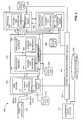
- FIG. 1is a schematic illustration of a multi-tier computing environment, generally referenced 50, which is known in the art.
- Computing environment 50includes a first client 62 running a first application, a second client 64 running a second application, a first tier 52, a second tier 54, a third tier 56, a fourth tier 58, and a fifth tier 60.
- the first tier 52is a web server.
- the second tier 54is an application server, application server A.
- the third tier 56is another application server, application server B.
- the fourth tier 58is a further application server, application server C.
- the fifth tier 60is a database.
- First tier 52is coupled with first client 62, with second client 64, and with second tier 54.
- Second tier 54is further coupled with third tier 56 and with fourth tier 58.
- Third tier 56is further coupled with fourth tier 58 and with fifth tier 60.
- Fourth tier 58is further coupled with fifth
- a "tier”represents a certain type of processing that is part of the overall delivery of an IT service (e.g., presentation level processing on a web server tier or data processing on a database tier). Each tier typically runs on a different host machine.
- the first applicationinitiates a user request R1 and sends user request R1 to first tier 52.
- User request R1is part of an overall transaction initiated by the user.
- User request R1may be, for example, a web based query to retrieve information from a certain application.
- User request R1may require the services of different tiers in computing environment 50 and may generate additional requests in order to obtain these services.
- the tier that receives a requesteither replies to the tier that sent the request, or sends a new request to a different tier. Eventually a reply is returned in response to the original user request R1.
- a given tiercan only request a service from another tier in computing environment 50 if the two tiers are directly coupled with each other.
- a system administratormay scale this tier by creating clones of the tier, both vertically (i.e., within the same host machine) and horizontally (i.e., across multiple host machines). For example, in computing environment 50, the system administrator may add an additional application server A2 (not shown) to second tier 54 application server A, wherein application server A2 is a clone of application server A.
- application server A2is a clone of application server A.
- the system administratormay further configure a certain tier in order to improve the overall performance or indicate modifications to optimize the application running on the tier.
- Thisis an example of tier specific application monitoring for performance management. It is noted that a request might reach only certain tiers in computing environment 50. Furthermore, the same request might reach certain tiers using multiple paths. For example, in computing environment 50, a request may reach fifth tier 60 database via either third tier 56 application server B, or via fourth tier 58 application server C. As the request paths are not consistent across the entire environment, solving the resource shortage on one tier does not necessarily guarantee the performance of the overall application, which may span multiple tiers. A processing bottleneck in any tier will delay all application functions that depend on that tier.
- First tier 52receives user request R1.
- First tier 52allocates processing enclave X1 to process user request R1. While processing user request R1, the application logic executing in processing enclave X1 determines it cannot complete processing user request R1 without additional information or operations to be provided by second tier 54.
- First tier 52then sends a subsequent request R2 to second tier 54, requesting the additional information or operations.
- Second tier 54allocates processing enclave X2 to process request R2.
- the application logic executing in processing enclave X2determines that request R2 requires further information or operations to be provided by fourth tier 58.
- Second tier 54then sends a subsequent request R3 to fourth tier 58.
- Fourth tier 58allocates processing enclave X4 to process request R3.
- Processing enclave X4completes execution.
- Fourth tier 58returns a reply R3' to second tier 54, in response to earlier request R3 of second tier 54.
- Processing enclave X2receives reply R3' and resumes processing.
- second tier 54returns a reply R2' to first tier 52, in response to earlier request R2 of first tier 52.
- Processing enclave X1receives reply R2' and resumes processing.
- first tierreturns a reply R1' to user request R1, whose service has now been completed.
- each of the different tiersis isolated from the tiers which are not directly coupled therewith.
- request R3 from second tier 54 to fourth tier 58, directly coupled therewithdoes not necessarily include information relating to a former request R2, which was received in second tier 54 from first tier 52, nor does request R3 include information relating to user request R1.
- a given tierhas no way of obtaining certain information related to the request being processed at that tier, such as which user initiated the transaction, which requests preceded the request which is being processed at the given tier, or characteristics of requests which preceded that request.
- second tier 54cannot identify characteristics of request R2, such as whether the request was preceded by user request R1 sent to first tier 52, or that the transaction originated at user request R1 from first application 62.
- a priority levelis assigned to a processing enclave processing a request within a certain tier, that priority level is assigned taking into account only the minimal information which is available on the tier. This information includes the request characteristics (e.g., the tier login credentials used by the request) and perhaps information about the processing enclave processing that request (e.g., the database session identification).
- Requestsare generally processed on an equal priority basis (e.g., first-come-first-serve), though mechanisms operating to differentiate priority levels are available locally on a given tier.
- Performance managementmust be done on an individual tier basis, as the other tiers in computing environment 50 cannot be accounted for when dealing with a specific tier.
- a system administratorwho is responsible for managing a multi-tier computing environment such as computing environment 50 attempts to improve performance by adjusting the resource allocation for a given tier.
- US Patent No. 5,958,010 to Agarwal et al. entitled “Systems and methods for monitoring distributed applications including an interface running in an operating system kernel”,is directed to systems and methods for monitoring enterprise wide operation of a distributed computing system to develop business transaction level management data for system performance, usage trends, security auditing, capacity planning, and exceptions.
- a system having a distributed computing architectureincludes multiple workstations, servers, and network devices. Each workstation is representative of a computer system coupled to a network. Each workstation is capable of requesting service from any of the servers. Each workstation has a communication stack for exchanging data with the network.
- the systemfurther includes a plurality of monitoring agents, and a console module with a database connected therewith. Each monitoring agent has an external event interface that provides event information about various components of an enterprise. Each of the monitoring agents is associated with a respective one of the workstations or servers.
- the monitoring agentmay physically reside on the associated client or server thereof.
- the monitoring agentmonitors and collects data being exchanged between a client and the network, and between a server and the network.
- Each monitoring agentcan be a software module, a hardware device, or a combination thereof.
- Each monitoring agentpasses information representative of the collected data to the console module.
- the console modulestores this information within the database for analysis by an operator.
- An application program running on the console modulecan view the collected data to show system performance of any process or component of the enterprise.
- a system administratorcan develop enterprise level usage statistics and response times, develop charts and reports, and perform other relevant data analysis for determining user-defined statistics relevant to the operation of the enterprise.
- US Patent No. 6,108,700 to Maccabee et al entitled "Application end-to-end response time measurement and decomposition",is directed to a method and system for measuring and reporting availability and performance of end-to-end business transactions.
- the systemoperates on a client-server application architecture.
- the systemincludes three logical components: Event Generation, Transaction Generation, and Report Generation, as well as overall system management via System Administration.
- the Event Generation componentexists on every computer being measured in the architecture.
- Each computerhas one Agent, a plurality of Sensors and a plurality of Processors.
- the Sensorsinteract with platform components on which business applications run, monitor application activities, and detect changes of state.
- each of the Sensorsgenerates an event that describes the change in state, when and where the event occurred, and any extra data necessary to uniquely identify the event.
- An eventcontains a time-stamp and correlation data used later by the system to associate the event with other events into transactions.
- the Sensorsforward the generated events to their respective Agents.
- the Agentstemporarily store the data and may distribute the data to other system components having registered interest in the event.
- a Processoranalyzes the events and further deduces changes in state. The changes in state may be directly related to actions occurring within the business transaction platform components or derived by combining previously generated events from Sensors or other Processors to describe states achieved.
- the Processorsforward the generated events to their respective Agents.
- the Transaction Generation componenttypically exists in one of the computers in the network and includes a Director.
- the Directorreceives events from the Agents under control thereof. The events are examined, and correlated and collated into transactions based on transaction generation rules.
- the System Administratordetermines which transactions to generate.
- the Report Generation componentincludes a Manager.
- the Managercollects the transactions from the Directors.
- the collected transactionsare manipulated to obtain information relating to the availability and performance of business transactions.
- a report or continuous graphic monitoringcan be produced upon a specific or periodic request from a Graphical User Interface (GUI).
- GUIGraphical User Interface
- Report Generationincludes definition of the initial selection and processing of transactions, as well as the sorting and aggregation methods used to consolidate the transactions event data into availability and performance information.
- US Patent Application No. 2002/0129137 A1 to Mills et al. entitled "Method and system for embedding correlated performance measurements for distributed application performance decomposition”,is directed to techniques for embedding correlated performance measurements in transactions associated with a distributed application.
- the techniquesare used in accordance with application performance decomposition.
- Datais embedded in a communications protocol used to carry a transaction between application components in a distributed computing network, rather than altering the actual transaction data itself.
- the embedded datamay include a timestamp and duration measurement data.
- the format of the embedded datacombines a well-defined keyword prefix with a variable suffix that identifies the timing source, followed by a colon delimiter and whitespace, and followed by the time stamp and duration information.
- Subsequent processing stages of the distributed applicationcan interpret the communications protocol to glean processing durations of previous stages, in order to make decisions regarding treatment of the transaction.
- the measurement informationis embedded within the same distributed application described by the measurement information, so that completion of the transaction occurs simultaneous or contemporaneous with availability of knowledge of the transaction performance characteristics.
- a possible communications protocolis the HyperText Transport Protocol (HTTP).
- HTTPHyperText Transport Protocol
- WWWWorld Wide Web
- the application componentsmay be a client application running on a client and a server application running on an application server.
- the client applicationis a web browser
- the server applicationruns on a web server.
- An application transactionis the client application requesting content from the application server and the application server responding.
- Performance informationis generated to measure the round trip response time from the perspective of the client application, as well as to decompose the response time into the time taken by the server application to service the request and generate a reply.
- linesare added to the HTTP headers to carry performance measurement data, allowing the client to receive the server measurement duration in the HTTP Reply header.
- an apparatus for monitoring a selected tier in a multi-tier computing environmentincludes a context agent and a dynamic tier extension.
- the context agentis associated with a selected tier, and is coupled with other context agents, each of which is associated with a respective tier.
- the dynamic tier extensionis coupled with the context agent and with specific predetermined points of the selected tier, such as at least a request entry port of the selected tier.
- the dynamic tier extensionmonitors request traffic passing through the selected tier, the monitored request traffic including at least one entering request received at a request entry port from an adjacent tier.
- the dynamic tier extensionidentifies each request in the monitored request traffic and sends at least the request identifier to the context agent.
- the context agentalso receives information relating to the request context of the entering request from the context agent associated with the adjacent tier.
- the context agentassociates the information relating to the request context of the entering request with the entering request, in accordance with the received request identifier.
- the dynamic tier extensionmay further be coupled with a request exit port of the selected tier, and the monitored request traffic further includes at least one exiting request exiting the selected tier to an adjacent tier.
- the dynamic tier extensioncaptures the request context of the exiting request and sends at least the request identifier and information relating to the request context of the exiting request to the context agent.
- the context agentassociates the entering request with the exiting request, in accordance with the received information and request identifiers.
- the context agentfurther provides information relating to the request context of the exiting request to the context agent associated with the adjacent tier to which the exiting request was sent.
- a system for application performance management in a multi-tier computing environmentincluding a plurality of tiers.
- the systemincludes, for each of at least two monitored tiers of the plurality of tiers, a respective dynamic tier extension and a respective context agent.
- the dynamic tier extensionis coupled with at least a request entry port of the monitored tier.
- the context agentis coupled with the dynamic tier extension and with other context agents associated with the tiers that are directly coupled with the monitored tier.
- the dynamic tier extensionmonitors request traffic passing through the selected tier, the monitored request traffic including at least one entering request received at a request entry port from an adjacent tier.
- the dynamic tier extensionidentifies each request in the monitored request traffic and sends at least the request identifier to the context agent.
- the context agentalso receives information relating to the request context of the entering request from the context agent associated with the adjacent tier.
- the context agentassociates the information relating to the request context of the entering request with the entering request, in accordance with the received request identifier.
- the systemfurther includes a context network management server.
- the context network management serveris coupled with the context agents.
- the context network management servercollects and analyzes performance data received from the context agents.
- a method for application performance management in a multi-tier computing environmentincluding a plurality of tiers.
- the methodincludes, for each of at least two monitored tiers of the plurality of tiers, the procedure of receiving information relating to the request context of at least one entering request, the information including at least a request identifier and a transaction identifier.
- the methodfurther includes the procedure of monitoring request traffic passing through the monitored tier, the monitored request traffic including at least the entering request.
- the methodfurther includes the procedures of identifying the entering request in accordance with the request identifier, and associating the entering request with a transaction in accordance with the transaction identifier.
- the methodincludes, for each of at least two monitored tiers of the plurality of tiers, the procedure of monitoring request traffic passing through the monitored tier, the monitored request traffic including at least an entering request and an exiting request, the exiting request sent from the monitored tier to an adjacent tier.
- the methodfurther includes the procedures of determining information relating to the request context of the entering request, and identifying each request in the monitored request traffic.
- the methodfurther includes the procedures of associating the entering request with the exiting request, and sending information relating to the request context of the exiting request to a context agent associated with the adjacent tier.
- the disclosed techniqueovercomes the disadvantages of the prior art by providing a system and method for application performance management in a multi-tier computing environment.
- the systemmonitors the request entry ports and request exit ports of each tier, and detects the entry or exit of requests to or from a given tier, via a plurality of context agents.
- Each context agentis associated with a tier in the multi-tier computing environment, and capable of communicating with other context agents.
- a context agentcollects information relating to the execution of requests on the tier associated therewith.
- the context agentidentifies the request context of a user request.
- the context agentclassifies the user request into a request class.
- the context agentrelays characteristics of a request exiting the tier associated therewith, to a subsequent context agent associated with the tier to which the request is sent.
- the context agentassociates a request with a user request and with other previous requests in the same transaction.
- the context agentassigns a service class to the request in accordance with the request class and a locally stored active service class policy.
- the context agentmay perform intervention to influence the processing of the request, such as adjusting the order of the request on the queue at a request entry port to the tier, altering the priority of a processing enclave executing the request, altering the type of processing of a processing enclave executing the request, instructing the tier to allocate, or to deny, computational resources (e.g. central processing unit - CPU, memory, and the like) to process the request, putting the request on hold and freeing the processing enclave, or terminating the request.
- a context network management servermay profile the behavior of different types of requests across several tiers and may set an appropriate cross-tier service class policy. The system thereby provides for context related resource management at a transaction level, across the different tiers in the multi-tier computing environment.
- the disclosed techniqueprovides proactive transaction workload management capability across all tiers in an IT infrastructure chain.
- the systemintegrates with the IT infrastructure tiers, such as web, application, database, and middleware servers.
- the systemautomatically profiles workloads, helps classify the workloads, and enables a user to create appropriate service class performance policies.
- the systemcontinuously applies these policies to transactions across the tiers in the computing environment.
- the systemutilizes the existing IT infrastructure and enhances the existing IT infrastructure to enable the balanced delivery of services at optimal service levels consistent with business interests. The following terms are used throughout the description of the embodiments:
- tierrefers to an entity that delivers a certain type of service, wherein the service is part of the overall delivery of an IT transaction.
- the servicemay be presentation level processing on a web server tier, application functionality on an application server tier, data processing on a database tier, and the like.
- Each tiertypically runs on a different host machine, although there may be more than one tier operating on a single host machine, and a single tier may include multiple components residing on more than one host machine.
- the host machine on which at least one tier runs,is herein below referred to as a "tier host”.
- Examples of a tierinclude but are not limited to: a Java 2 Platform, Enterprise Edition (J2EE) application server instance; a cluster of J2EE application server instances; a database server instance including the access components to the database server such as Java Database Connectivity / Open Database Connectivity (JDBC/ODBC) drivers; a cluster database, and the like.
- J2EEJava 2 Platform, Enterprise Edition
- a cluster of J2EE application server instancesa database server instance including the access components to the database server such as Java Database Connectivity / Open Database Connectivity (JDBC/ODBC) drivers
- JDBC/ODBCJava Database Connectivity / Open Database Connectivity
- transactionrepresents a single process initiated by a user, such as a stage of a business process within a business application.
- An example of a transactionis the placing of a bid in an online auction service or the opening of a new customer account at a financial institution.
- a transactionis made up of a chain of requests between tiers, starting with a user request. Therefore each request is uniquely associated with a user request (i.e., the user request of the transaction).
- Each transactionis identified via a unique identifier, known as a "transaction ID”.
- a "set of related transactions”refers to several transactions which are interrelated (e.g., each transaction represents different stages of a single business process). The handling of a request within a transaction may take into account not only the transaction, but also the set of related transactions to which the request belongs.
- requestrefers to a system request from one tier to another tier, in order to provide a certain service that is part of the transaction.
- Each requestis identified via a unique identifier, known as a "request ID”.
- Each requestresults in a unit of work (UOW) on the invoked tier.
- Examples of a requestinclude but are not limited to: a client web browser issuing a HyperText Transport Protocol (HTTP) request to a web server; a JAVA program issuing a Remote Method Invocation (RMI) call to an application server; a J2EE application server session bean invoking an entity bean on a remote application server (via RMI), and the like.
- HTTPHyperText Transport Protocol
- RMIRemote Method Invocation
- the user requestis the first request in the chain of requests that makes up a transaction.
- the chain of requestscan be represented as a tree structure with the user request at the root node of the tree.
- UOWrefers to the application code executing in the processing enclave allocated to the applicable request on that tier (i.e., a UOW invocation).
- a UOWis associated with a source and a destination, may have parameters (which are directives for the application code behavior), and uses tier level resources within a single tier.
- processing enclaverefers to any thread, sub-process, database session, and the like, which executes a UOW in a given tier.
- a requestis queued in the tier until an available processing enclave is allocated and the application code (i.e., a UOW) is assigned to the processing enclave.
- Processing enclavesare generic execution units which in turn execute different application codes.
- the term "request context” herein belowrefers to a set of characteristics that are initially captured from the user request, sent to subsequent requests along the chain of requests of the transaction, and may be modified at any tier along the way.
- the request contextenables the disclosed technique to identify, track and prioritize the resulting chain of requests as part of the single transaction initiated by a user request.
- the request contextmay include for example, the characteristics of the user who submitted the request, the characteristics of the item that is the subject of the request, the geographical location from which the request originated, the time and date at which the request is made, the set of related transactions to which the request belongs, and the like. Certain parts of the request context may be modified at subsequent tiers. For example, the service class of the user request that is added to the request context at the first tier, may be overridden by a subsequent tier (i.e., according to another embodiment of the disclosed technique).
- request classrefers to a category of transactions which share one or more pre-defined request context characteristics. For example, a "stock portfolio summary query” may be classified as a “stock portfolio summary query” request class, or may be part of a larger “stock portfolio query” request class together with another transaction, such as a "stock portfolio history query”. Each request class is treated in accordance with an active service class policy. Once a request class is assigned to the user request, that request class is automatically assigned to each subsequent request in the transaction initiated by that user request.
- service classrefers to a set of rankings for various parameters that indicate the level of importance for processing the request.
- the parametersmay include: the priority to be assigned to the request, the CPU percentage to be allocated to the request, the memory to be allocated to the request, the priority in allocating and accessing input/output (I/O) devices to the request, and the like.
- the service classis assigned to a request executing on a given tier by the respective context agent, in accordance with the appropriate active service class policy.
- service class policyrefers to a rule which assigns a service class to a request within a request class, with respect to the tier on which the request is being processed.
- Each context agentcontains a set of tier specific service class policies, each of which maps a service class to a request class for the specific tier associated with that context agent.
- a "cross-tier service class policy database”describes the set of mappings of service classes to request classes for all the tiers in the multi-tier computing environment. It is noted that a user may define a set of service class policies. Such policies are referred to herein below as "user-defined service class policies”.
- active service class policycontains the request class to service class mapping that is currently in effect. Multiple service class policies are supported and a different service class policy may be scheduled at different times of system operation to reflect changing workloads or various system events, or simply as an ad hoc decision.
- System 100operates on a multi-tier computing environment, generally referenced 132.
- Computing environment 132includes a first client 112 running a first application, a second client 114 running a second application, a first tier 102, a second tier 104, a third tier 106, a fourth tier 108, and a fifth tier 110.
- the first tier 102is a web server.
- the second tier 104is an application server, application server A.
- the third tier 106is another application server, application server B.
- the fourth tier 108is a further application server, application server C.
- the fifth tier 110is a database.
- First tier 102is coupled with first client 112, with second client 114, and with second tier 104.
- Second tier 104is further coupled with third tier 106.
- Third tier 106is further coupled with fourth tier 108 and with fifth tier 110.
- Fourth tier 108is further coupled with fifth tier 110.
- the first application running on first client 112initiates a user request R1.
- the second application running on second client 114initiates a user request 118.
- System 100includes a plurality of context agents 122, 124, 126, 128 and 130, and a context network management server (CNMS) 120.
- CNMScontext network management server
- context agents 122, 124, 126, 128 and 130are associated with first tier 102, second tier 104, third tier 106, fourth tier 108 and fifth tier 110, respectively.
- Context agents 122, 124, 126, 128 and 130are coupled with CNMS 120.
- Each context agentis also coupled with other context agents in accordance with the coupling of the tiers in computing environment 132.
- context agent 122is coupled with context agent 124
- context agent 124is further coupled with context agent 126
- context agent 126is further coupled with context agent 128 and with context agent 130
- context agent 128is further coupled with context agent 130.
- First client 112requires a service from first tier 102 and first client 112 sends a user request R1 to first tier 102.
- User request R1waits on a queue at a request entry port of first tier 102.
- First tier 102assigns an available processing enclave X1 to process user request R1. While processing user request R1, the application logic executing in processing enclave X1 determines that processing enclave X1 cannot complete processing user request R1 without additional information or operations to be provided by second tier 104. Therefore, first tier 102 sends a new request R2 to second tier 104, requesting the additional information or operations. Second tier 104 assigns an available processing enclave X2 to process request R2.
- the application logic executing in processing enclave X2determines that processing enclave X2 requires further information or operations to be provided by third tier 106. Therefore, second tier 104 sends a new request R3 to third tier 106. Third tier 106 assigns an available processing enclave X3 to process request R3. It is noted that each of requests R1, R2, and R3 is part of a single transaction which originates from the application running on first client 112.
- Processing enclave X3completes processing.
- Third tier 106returns a reply R3' to second tier 104, in response to the earlier request R3 from second tier 104.
- the application logic executing in processing enclave X2receives the reply R3' and resumes execution.
- second tier 104returns a reply R2' to first tier 102 in response to the earlier request R2 from first tier 102.
- the application logic executing in processing enclave X1receives the reply R2' and resumes execution.
- first tier 102returns a reply R1' to user request R1, which has now completed.
- Each context agentmonitors the tier associated therewith at the request entry ports and request exit ports of the tier (represented as small circles in Figures 2 and 3).
- the context agentmonitors request traffic passing through the associated tier, by detecting that a request has entered or exited the associated tier. If the request is a user request (i.e., the initial request in a chain of requests), the context agent of the first tier identifies the request context of the user request, classifies the user request into a request class, and assigns a service class to the user request based on the contents of the active service class policy.
- Each context agenthas a policy cache (not shown) which contains the set of tier specific service class policies for the tier associated with the respective context agent.
- CNMS 120periodically updates each context agent with the tier specific active service class policies. If the request is not a user request, the context agent receives information relating to the request context of the request, along with additional information relating to the request (i.e., "context information"), from the context agent associated with the tier where that request originated.
- Context informationthe minimal information included in the context information that a context agent relays to another context agent is at least: the request ID, the transaction ID, the request class, and context related data associated with the request.
- Context related datamay include the request context itself, or an indication (e.g., a pointer) to the request context residing in another location.
- the context agentassociates the received context information with the request executing on the tier.
- the context agentmay influence the processing of the request, by the respective tier, in accordance with the service class assigned to the request. For example, the context agent may adjust the order of the request on the queue at a request entry port to the tier, or may instruct the tier to allocate, or alternatively to deny, computational resources from the tier to execute the request. If the context agent detects that a request has exited the associated tier, the context agent relays context information to another context agent associated with the tier to which the request has been sent. This other context agent associates the received context information with the relevant request, and with the processing enclave executing the request on the tier associated with this other context agent.
- the context agentmonitors the request entry ports and request exit ports of the tier, rather than extensively monitoring the activity that occurs within the tier itself (e.g., the processing enclave executing a request).
- system 100does not interfere with the actual operation of a given tier or the user application code executing in the tier from a software perspective, and system 100 adds minimal additional load to the tiers.
- the context agentis also coupled with the associated tier via a dynamic tier extension (DTE - not shown in Figure 2).
- DTEdynamic tier extension
- the DTEenables the context agent to collect data relating to the execution of UOWs on that tier.
- the context agentsmay send raw data to CNMS 120 for archiving purposes.
- the context agentsmay further send to CNMS 120 statistical data for aggregated analysis.
- the context agentsmay receive information from CNMS 120 such as activity profiles (defined herein below with reference to Figure 6) and new active service class policies for the handling of different types of request classes.
- the context agentis elaborated upon in detail in Figure 8 herein below.
- context agent 122monitors first tier 102 and detects that user request R1 has entered first tier 102.
- Context agent 122identifies the request context of user request R1 and associates user request R1 with processing enclave X1 processing the request.
- Context agent 122classifies user request R1 into an appropriate request class.
- Context agent 122determines the service class of user request R1 in first tier 102, by retrieving the appropriate active service class policy in the set of service class policies context agent 122 has stored, and assigns user request R1 the determined service class.
- Context agent 122adds the assigned service class to the request context.
- context agent 122detects that request R2 is related to user request R1.
- Context agent 122then sends context agent 124 information relating to the request context of user request R1, together with the request ID, the request class, and the transaction ID associated with request R2.
- Context agent 122sends context agent 124 a message 134.
- Message 134includes the request ID of request R2, the transaction ID of request R2, the request class that context agent 122 classified request R2 into, and the request context of request R2.
- Context agent 124receives message 134 and determines the service class of request R2 which is to be executed on second tier 104, by retrieving the appropriate active service class policy in the set of service class policies which context agent 124 has stored.
- Context agent 124assigns request R2 the determined service class. For example, the request class of request R2 is group "15".
- Context agent 124retrieves the active service class policy that maps a service class to requests of request class "15" that are executing on second tier 104.
- the appropriate service class policyassigns a priority of "5" to such requests, a CPU allocation of "90”, a memory allocation of "48”, and I/O device access priority of "2".
- Context agent 124may then influence the processing of request R2 in accordance with the assigned service class.
- System 100performs application performance management on a request context basis.
- System 100identifies the requests, and the characteristics relating to each request are available at the context agent associated with the tier. These characteristics may include where that request initiated, which requests preceded the request in the transaction, and what type of request it is.
- context agent 124identifies that request R2 operating on second tier 104 is associated with user request R1 that was processed by first tier 102 and initiated in first client 112. Since the context agent of a given tier is aware of the request context and the request class of each request which is being executed at the respective tier, the context agent can determine the appropriate tier specific service class of the respective request based on the service class policy.
- CNMS 120can set the overall management policy across several tiers, respective of different request classes, and update the context agents accordingly.
- FIG 4is a schematic illustration of a sample request life cycle, generally referenced 140, over two of the tiers of the system of Figure 2.
- Sample life cycle 140depicts the stages a request undergoes as the request is being serviced in multi-tier computing environment 132 ( Figure 2). It is recalled that a request causes an invocation of a UOW, which may further generate additional requests, either internally within the same tier (by sending a request to the same tier on which the UOW is being executed), or externally (by sending requests to other tiers). Hence, a user request typically spawns a series of invocations of UOWs, each of which may be performed on a different tier.
- the invocations of UOWsmay be synchronous (i.e., the processing enclave executing the invoking UOW waits for a reply from the invoked UOW before resuming processing) or asynchronous (i.e., the processing enclave executing the invoking UOW continues to process the invoking UOW without waiting for a reply from the invoked UOW).
- the UOW on the invoked tier N+1is dedicated to the service requested by the invoking tier N.
- the invoking UOW on tier Nwaits for the invoked UOW on tier N+1 to end (i.e., the UOW on tier N+1 is de-allocated).
- the invoked UOW on tier N+1may be referenced multiple times by the invoking tier, until the invoked UOW on tier N+1 ends.
- a first requestis sent to tier N (i.e., any representative tier) in computing environment 132.
- the first requestresults in a UOW invocation on tier N to provide a service, either for a previous tier or for a user application.
- the first requestwaits on a queue 158 on tier N.
- the first requestexits queue 158 and is allocated a UOW, UOW-A, on tier N.
- a UOW allocationinvolves assigning an available processing enclave from one of processing enclaves 162 in tier N and dispatching the request application code to run on that processing enclave. The UOW allocation occurs once target tier resources are available and it is possible to assign the application code to an available processing enclave on tier N.
- UOW-Acommences execution on tier N.
- UOW-Aissues a second request to tier N+1.
- Tier N+1then invokes UOW-B to execute this request of tier N.
- tier N+1invokes UOW-B to execute the second request sent by tier N.
- the second requestwaits on a queue 160 on tier N+1.
- stage 150the second request exits queue 160 and UOW-B is allocated to the second request.
- UOW-B allocationresults in the assignment of an available processing enclave from one of processing enclaves 164 on tier N+1 to the application code of the UOW invocation and dispatching the request application code to run on that processing enclave.
- UOW-Bthen commences execution on tier N+1. It is noted that the invocation of UOW-B is synchronous, and thus the processing enclave processing UOW-A does not continue processing while waiting for a reply from UOW-B.
- the processing enclave processing UOW-Areceives an acknowledgement from tier N+1 that the second request sent from UOW-A to tier N+1 was accepted. Upon receiving the acknowledgement, the processing enclave processing UOW-A resumes execution until the processing enclave eventually returns a reply to the first request. After tier N+1 accepts the asynchronous second request, the second request waits on queue 160. The second request is subsequently read by one or more processing enclaves handling the second request, until one of these processing enclaves also removes the second request from queue 160. Each processing enclave handling the second request may also turn the second request into a new user request, which may itself start another chain of requests, thereby starting a new transaction.
- a transaction involving an asynchronous requestmay be a user confirming the purchase of a book in an e-commerce website.
- the purchase requestreturns the user to a screen informing that the order is being processed and the user will be notified (e.g., via email or text message).
- the same purchase requestis simultaneously placed on a message queue where the purchase request is later processed by: a processing enclave sending a final approval request to the credit card company; a processing enclave sending a purchase order request to the warehouse; a processing enclave sending an accounting request to the billing system; and the like.
- UOW-Breturns a reply to UOW-A in response to the earlier invocation of UOW-A, and execution of UOW-B is now completed.
- the second requesthas now terminated.
- UOW-Areceives the reply and resumes execution, at which point UOW-B is actually released by tier N+1. UOW-A may then continue executing.
- the duration of time between when an invoking UOW makes a request and when the invoking UOW receives a reply from the invoked UOW,is known as the "latency" period, or the response time for a given UOW request.
- UOW-Acompletes execution and the first request terminates. It is noted that before completion, UOW-A may require the services of another tier and may invoke a further request in order to provide that service.
- an unrecoverable errormay occur (e.g., a program exception).
- the context agent associated with tier N+1will record the error and will associate the error to the transaction which commenced with the user request that invoked UOW-A on tier N, providing information as to the nature of the error that occurred on tier N+1.
- System 200operates on a multi-tier computing environment, generally referenced 248.
- Computing environment 248includes a client 214, a first tier 202, a second tier 204, a third tier 206, a fourth tier 208, and a fifth tier 210.
- First tier 202is a web server.
- Second tier 204is an application server A.
- Third tier 206is an application server B.
- Second tier 204 and third tier 206both reside on a single host machine 212.
- Fourth tier 208is another application server, application server C.
- Fifth tier 210is a database.
- First tier 202is coupled with client 214, and with host 212.
- Host 212is further coupled with fourth tier 208 and with fifth tier 210.
- Fourth tier 208is further coupled with fifth tier 210.
- System 200includes a plurality of dynamic tier extensions 222, 224, 226, 228 and 230, a plurality of context agents 232, 234, 236 and 238, a plurality of local logs 240, 242, 244 and 246, a context network management server (CNMS) 216, a service level objective (SLO) policy database 218, and a supervisor workstation 220.
- Each tiercontains a dynamic tier extension (DTE).
- DTEdynamic tier extension
- a context agent of a given tieris coupled with the DTE (or several DTEs) within the tier, with the local log associated with the context agent, and with other context agents in accordance with the coupling of the tiers in the computing environment.
- Each context agentis also coupled with CNMS 216.
- CNMS 216is coupled with SLO policy database 218.
- Supervisor workstation 220is coupled with CNMS 216 and with SLO policy database 218.
- first tier 202includes DTE 222.
- Context agent 232is associated with first tier 202.
- Local log 240is associated with context agent 232.
- Second tier 204includes DTE 224.
- Third tier 206includes DTE 226. Since second tier 204 and third tier 206 both reside on host 212, there is only a single context agent 234 associated with both second tier 204 and third tier 206. It is noted that context agent 234 is directly coupled with each of DTE 224 and DTE 226.
- Local log 242is associated with context agent 234.
- Fourth tier 208includes DTE 228.
- Context agent 236is associated with fourth tier 208.
- Local log 244is associated with context agent 236.
- fifth tier 210includes DTE 230.
- Context agent 238is associated with fifth tier 210. Local log 246 is associated with context agent 238.
- Context agent 232is coupled with context agent 234.
- Context agent 234is further coupled with context agent 236 and with context agent 238.
- Context agent 236is further coupled with context agent 238.
- a dynamic tier extensionis coupled with the tier at specific predetermined points. These predetermined points are: the request entry ports of the tier, the request exit ports of the tier, and possibly additional areas within the tier (e.g., a tier control port).
- a request port according to the disclosed techniqueis a module within a tier which manages requests, either before they are processed by the tier, or after they are processed by the tier. Such a request port can be an interface point (i.e., entrance, exit or any other access mechanism) to a request queue at the entrance of a tier. Since a request requires service from an application code running on the tier by a processing enclave, the respective request port resides at an application level and not at a networking level. It is noted that request ports according to the disclosed technique, are not at a network level (e.g., not TCP/IP or UDP ports).
- the DTEis located on the same tier host as the tier associated therewith (i.e., the DTE is located on at least one of the host machines on which the tier is running). Among the responsibilities of the DTE is capturing a request context. The DTE further monitors the request entry ports and request exit ports of a tier, to detect incoming and outgoing requests. The DTE assigns a transaction ID to a user request, and obtains the request ID of each request entering or exiting the tier. The DTE is elaborated upon in detail in Figure 7 described herein below.
- the context agentmaintains associations between a given request, the invoked UOW of the request, and the request context of the user request in the same transaction as the request.
- the context agentrelays the request context assigned to each request (i.e., context related data) to other context agents handling other tiers.
- the context agentmay relay the entire request context, or a portion of the request context.
- the context agentmay relay the request context itself, or an indication (e.g., a pointer) to the request context residing in another location. It is noted that the context agent need not necessarily reside on the same host machine as the tier, but this is the case in a preferred embodiment of the disclosed technique.
- the context agentis elaborated upon in detail in Figure 8 described herein below.
- CNMS 216collects and analyzes performance data.
- SLO policy database 218stores cross-tier service class policies, and is continuously updated.
- FIG. 6is a schematic illustration of two of the tiers of the multi-tier computing environment of Figure 5. It is noted that each of fourth tier 208 and fifth tier 210 illustrated in Figure 6 is representative of any two consecutive tiers (e.g., tier N and tier N+1) in computing environment 248.
- a request entering fourth tier 208waits at a request entry port of fourth tier 208 at a queue 262.
- Fourth tier 208invokes a UOW to execute the request.
- the requestexits queue 262 and fourth tier 208 allocates the UOW to the request, by assigning an available processing enclave to the UOW from processing enclaves 252 and dispatching the request application code to run on the processing enclave.
- the UOWexecutes on fourth tier 208.
- the UOWmay then request a service from fifth tier 210.
- the new requestexits fourth tier 208 at a request exit port and waits at a request entry port of fifth tier 210 at a queue 264.
- Fifth tier 210invokes a UOW to execute the new request.
- DTE 228monitors the request entry ports and request exit ports of fourth tier 208 to detect the requests entering and exiting fourth tier 208, respectively.
- the dynamic tier extensionsare involved in tracking a request throughout the life cycle thereof, without changing the application code.
- the DTEdynamically hooks into the tier environment where the DTE intercepts the request context external to the application code.
- Request trackingincludes capturing the request context, associating the request to a UOW on a tier, and disassociating the request from a UOW on a tier.
- the DTEfurther collects performance, availability, and error metrics from the tier.
- the DTEalso may dynamically adjust the processing of requests on the tier, such as by adjusting the order of a request on the queue at a request entry port of the tier, allocating computational resources to process the request (e.g., CPU, memory, I/O, and the like) or altering the priority of the processing enclave or the allocated resources.
- computational resourcese.g., CPU, memory, I/O, and the like
- altering the priority of the processing enclave or the allocated resourcesare elaborated upon with reference to Figures 9, 10 and 11 described herein below.
- in-band context relaythere are two alternatives for request context relaying between context agents: in-band and out-of-band.
- in-band context relaythe request context is added to the request itself (i.e., onto the payload), as the request exits a certain tier toward the next tier. Therefore, as a request and descendant requests thereof are being processed between different tiers, the updated request context is added to the request invocations.
- out-of-band relayingdoes not involve the request context being added to the request invocations. Rather the context agents send the context information directly to each other.
- a context agentsends a request context to another context agent.
- a DTEretrieves the request context from the context agent. It is noted that each context agent of a system similar to system 200 ( Figure 5) relays the request context to another context agent using the out-of-band technique.
- system 200performs activity profiling.
- Activity profilinginvolves creating an activity profile.
- the activity profileincludes integrated transaction, tier, and system level performance metrics and statistical analysis, which are obtained during request tracking.
- the performance metricsmay include: request elapsed time, request service time, consumed CPU time on the tier, and the like.
- the activity profile datais collected over time and used for both monitoring (i.e., display in the GUI) and for supporting user creation of a user-defined service class policy.
- An activity profiling console(not shown) is a component of the GUI that displays performance and availability aggregated data gathered by the context agent.
- the performance and availability aggregated dataincludes summary views of activity profile data by various categories such as: tier, request class, transaction and the like.
- An activity profiling enginelocated in CNMS 216 performs activity profiling.
- Each context agenthas the task of collecting information about the execution details in each tier.
- the DTEenables the context agent to collect data relating to the execution of UOWs on that tier.
- the context agentsthen send the collected information to CNMS 216.
- the information stored for each UOWincludes: start time, request ID of the request to which the UOW is allocated, transaction ID of the request to which the UOW is allocated, request class of the request to which the UOW is allocated, user details, originating network address details, service class of the request to which the UOW is allocated, end time, resource consumption (such as a CPU), and the like.
- the context agentstores the information relating to currently executing UOWs in a memory (not shown). Once the UOW has finished executing on the tier the context agent transfers the information to a recent history data store (not shown), which is stored on a disk (not shown) locally at the same tier host of the context agent. After a certain period, the context agent moves the entries from the recent history data store to a summary data store (not shown). This information is stored as a summary over a given period of time (e.g., an average of collected metrics over a period of half an hour). The information in the summary data store is stored in shifts. Shifts are saved on a periodic basis (i.e., they are recycled after a number of shifts have accumulated).
- System 200further includes service class policies.
- a service class policyrefers to a rule which assigns a service class to a request within a request class, with respect to the tier on which the request is being processed.
- a real time service class policy enginelocated in the context agent, assigns an appropriate service class to the request in accordance with information in the request context, such as the request class, performance characteristics of previous executions of requests with the same request context, and in accordance with an active service class policy.
- assignment of a service classmay take into account additional considerations, such as a set of performance metrics for each request class. This set of performance metrics characterizes the request class and creates a baseline for typical performance behavior. This process utilizes the log data created across all tiers and the request classes associated with them.
- the request classesare stored in a tree structure in SLO policy database 218.
- the service class policy engineadds and updates information relating to each request class, and updates SLO policy database 218 accordingly.
- the service classis determined for the user request in the first tier and then passed from tier to tier along with the request in the request context (from context agent to context agent). There is no need to access CNMS 216 in order to determine the active service class policy and the mapping to the service class. Rather, each context agent has a policy cache therein (not shown) kept up to date, so that the mapping to the appropriate service class is performed locally.
- the activity profiling enginepolls the local context agents for information about completed and currently running requests at periodic intervals, or whenever necessary and on demand (e.g., when a user wishes to view the currently running requests on the performance console). Alternatively, the activity profiling engine can instruct each context agent to initiate sending new records to the activity profiling engine at fixed intervals or when a threshold (i.e., number of records) is reached.
- the activity profiling enginecollects the data for each request, performs calculations (e.g., average, variance, and the like) and stores the results at various intervals in SLO policy database 218, as a baseline for analysis for each request class.
- a service class policy generation engine located in CNMS 216creates a set of rules that serve as recommendations for new service class policies. CNMS 216 determines service class policies using these recommendations. The service class policies are stored in SLO policy database 218.
- SLO policy database 218stores policies that are automatically generated as well as user-defined service class policies.
- a usermay create a set of service class policies (i.e., user-defined service class policies) via the user interface (not shown) of system 200, or by editing a configuration file of the context agent.
- the creation of user-defined service class policiesinvolves user analysis of the activity profiles, and obtaining approval of the suggested service class policy by CNMS 216.
- the context agentreceives updated service class policies from CNMS 216. It is noted that whether the new service class policy is automatically generated or user-defined is transparent to the context agent.
- the context agentassigns to a request the service class designated in the appropriate tier-specific active service class policy, located within the local policy cache of the context agent.
- the context agentmay assign the request a different service class than that designated by the active service class policy in certain situations (e.g., if the tier is currently unable to provide all the resources required to fulfill the service class, if a significant amount of high priority requests enter the tier and may result in resource starvation for lower priority requests, and the like). Further alternatively, the context agent may alter the request class of the request, and subsequently assign the request the service class designated by the appropriate tier-specific active service class policy for the new request class.
- System 200also performs request classification. This involves classifying multiple requests (each designated by their transaction ID and request context) into request classes according to various criteria.
- An automatic request classification processgathers the generic information associated with a request (e.g., header information, parameters such as query string, Uniform Resource Locator (URL) parameters in the case of an HTTP request type, and the like). When another request of the same request class arrives, this request will be treated in a similar manner as other requests within the request class.
- the request classesmay be grouped into various categories in accordance with the request class performance characteristics in the relevant activity profiles (e.g., a group of request classes having a response time greater than two seconds). Request class grouping is used for reporting purposes, enabling higher level summarized views of request class performance data.
- System 200also supports a user defined classification process wherein the user creates rules that classify requests based on the same request information used for the automatic classification process.
- a usermay create classification rules via the user interface (not shown) of system 200.
- the automatic request classification processuses a "class based cache management" algorithm, as described by H. Zhu and T. Yang ("Class- based cache management for dynamic web contents," Tech. Rep. TRCS00-13, Dept. of Computer Science, University of California, Santa Barbara, 2000).
- the output of the classification processis a tree representing the request class and the parent classes (i.e., in an automatic request classification process) or a set of classification rules (i.e., in a user defined classification process). All the results of classification processes are stored in the SLO policy database 218.
- System 200is also operative to enforce the service class, as defined in the active service class policy, on each and every monitored tier. Policy enforcement is performed by both the DTE and the context agent. Enforcement may be implemented either by controlling the queuing of requests in each tier (i.e., the order in which the request is actually processed within the tier), or by temporarily changing the processing priority of the processing enclave running the request during execution.
- implementation in a database tiermay involve use of a database resource management scheme to manipulate session resource allocation according to the appropriate service class policy.
- implementation in an application server tier implemented using a J2EE Application Server applicationwhich may involve: extending the application server web queue to support request prioritization, extending the Enterprise JavaBeans (EJB) queue to support prioritization, controlling the JAVA thread priority, and the like.
- EJBEnterprise JavaBeans
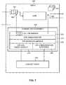
- DTE 228 of fourth tier 208is representative of all the dynamic tier extensions in system 200.
- DTE 228includes a series of soft hooks or interception points into fourth tier 208. These hooks, referenced 266 and 268, serve to collect request related information and performance data. The hooks can also alter the priority of a processing enclave executing a UOW. A hook places the collected information on a dedicated message queue 270. The soft hooking and interception technique depends on the particular environment.
- the environmentmay be: a web server, a JAVA based J2EE application server, a database, a messaging server, and the like. It is noted that interception points 266 and 268 may be instantly activated or deactivated by an operator.
- DTE 228further includes a process running within fourth tier 208. The process handles messages from the interception points, communicates messages to context agent 236, returns messages to the interception points, and performs administrative control functions of the DTE (e.g., start/stop tracking requests, installing and removing soft hooks).
- DTE 228includes a DTE daemon 272, a DTE administrator 274, a DTE messaging module 276, a DTE log event handler 278 and a DTE communication interface 280.
- DTE daemon 272is an artificially created processing enclave operating within the tier. DTE daemon 272 performs asynchronous processing associated with reported events where the request does not need to be detained. There are two types of scenarios concerning reporting events. In the first scenario, there is no need to detain the request until a response is received. For example, when reporting that a request has ended, there is no need to delay the request until after the context agent has actually been notified. In the second scenario, the request needs to be held for a certain period before processing may resume. For example, when obtaining the service class of a request or when performing classification of a request, processing cannot commence until the request class and service class is determined by the context agent, otherwise processing may be done using an incorrect service class or an incorrect request class.
- DTE daemon 272deals with events of the first scenario, where the request does not need to be detained. The processing is done asynchronously, such that the request is not delayed. The request is thereby released very quickly, almost instantaneously. DTE daemon 272 has a queue 270 associated therewith. After request entries and related request exits are notified by interception points 266 and 268, DTE daemon 272 picks up these notifications from queue 270 and performs whatever additional processing is necessary.
- DTE administrator 274enables DTE 228 to receive messages relating to how requests should be processed. For example, such messages may include: stop tracking a request, continue tracking the request but stop prioritizing, and the like.
- DTE messaging module 276communicates with context agent 236 using messages. For example, such messages may include: start or end of a UOW, associate a UOW with a given request, and the like.
- DTE log event handler 278logs tracing information concerning DTE operations and logs alerts raised by DTE 228. These logged events could be sent to multiple destinations such as a local file, system message console, system log, and the like.
- DTE log event handler 278supports multiple industry standard protocols such as Simple Network Management Protocol (SNMP), and the like.
- SNMPSimple Network Management Protocol
- DTE communication interface 280serves as an interface between DTE 228 and context agent 236.
- DTE communication interface 280relays messages sent from agent messaging module 286 of context agent 236 to DTE 228.
- DTE communication interface 280also relays messages sent from DTE messaging module 276 of DTE 228 to context agent 236.
- Multiple communication protocolsare supported, and each DTE uses the most efficient communication method available within its architecture, such as inter process communication, Transmission Control Protocol/Internet Protocol (TCP/IP), and the like.
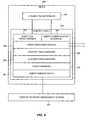
- Context agent 236 of fourth tier 208is representative of all the context agents in system 200.
- Context agent 236receives notifications from DTE 228 via a variety of mechanisms, such as TCP/IP, inter-process communication channels, and the like. The notifications are of events occurring within the tier, such as: the capture of a request context, the start of an UOW, the end of an UOW, resource consumption of an UOW, the invocation/allocation of an UOW on a remote tier, the reply/release of an UOW on a remote tier, and the like.
- Context agent 236includes an agent log event handler 282, an agent communication interface 284, an agent messaging module 286, a context table manager 288, a classification manager 290, a policy manager 292, and an agent administrator 294.
- Agent log event handler 282is used by context agent 236 both for internal housekeeping purposes and for logging alerts raised by context agent 236. Agent log event handler 282 logs information that enters the context table (as described herein below), but is also used for internal tracing and messaging purposes, such as to detect operational irregularities (i.e., problems or errors) that may occur within context agent 236. These logged events can be sent to multiple destinations such as a local file, system message console, system log, and the like. Agent log event handler 282 supports multiple industry standard protocols such as SNMP, and the like.
- Agent communication interface 284serves as an interface between DTE 228 and context agent 236. Agent communication interface 284 relays messages sent from DTE messaging module 276 of DTE 228 to context agent 236. Agent communication interface 284 also relays messages sent from agent messaging module 286 of context agent 236 to DTE 228. There may be several channels connecting DTE 228 and context agent 236, to ensure fast and reliable communication between the two, and at least several channels are kept open at all times, for example a high priority channel and an administrative channel. There may also be several connections of each type of channel, for different types of messages. As a result, agent communication interface 284 is operative to accommodate these different possibilities.
- Agent messaging module 286notifies other context agents associated with remote tiers that a request was sent to the remote tier. Agent messaging module 286 further communicates with DTE 228 using messages. For example, such message include: start or end of a UOW, associate a UOW with a request, and the like. Agent messaging module 286 communicates with DTE 228 via agent communication interface 284.
- Context table manager 288functions as the bookkeeper of the context agent. Context table manager 288 maintains a cross-reference table, known as a "context table", used to associate UOWs running on the tier to their request context.
- the request contextmay be from the current tier (i.e., in the case of a user request), relayed from a previous tier from the request execution chain, or both (i.e., the request context is modified or new information is added therein).
- the context tablestores information associated with each request (e.g., transaction ID, request class, service class, origin of request, and the like). Agent messaging module 286 accesses the context table and looks up a record of interest after agent messaging module 286 has received information from DTE 228.
- Context table manager 288identifies a request based on information associated with the request and the data stored in the context table. In this manner, context agent 236 obtains information relating to the request entering the tier, such as the request class, service class, and other relevant information associated with the request.
- Classification manager 290 and policy manager 292process each user request that enters the first tier.
- all the information known about the user request at a request entry portis collected. For example, if the user request is an HTTP request, then such information includes the HTTP header, the query string, the URL parameters, and the like.
- HTTPHyperText Transfer Protocol
- the classification processessentially extracts the business perspective from the user request, by translating technical request related information (e.g., an HTTP request) into a formal request classification related to a business process (e.g., retrieve bank account balance).
- a user requestis placed into a specific request class.
- the user requestmay be identified as part of a business process or a set of related transactions. For example, retrieval of an account balance may be part of a larger process of applying for a mortgage.
- CNMS 216can determine the activity profile and detect request behavior trends for request classes.
- Policy manager 292assigns a service class to the requests.
- Policy manager 292receives the output of classification manager 290, and based on the request class, the request context, and the active service class policy, determines the service class of a given request. For example, policy manager 292 may set all requests from a certain request class to have a service class with a higher priority than all requests from a different request class.
- a context agentassigns a service class to a request being processed on the tier associated therewith, by updating the request context with the appropriate service class according to the active service class policy.
- the cross-tier service class policy databaseincludes the set of mappings of service classes to request classes for all the tiers in the multi-tier computing environment. Each request belonging to a certain request class may be assigned a different service class depending on the tier in which the request is being processed. With reference to Figure 2, user request R1 may be assigned a service class with a low priority on first tier 102, request R2 may be assigned a service class with a high priority on second tier 104 and request R3 may be assigned a service class with a medium priority on third tier 106.
- the cross-tier service class policiesare stored in SLO policy database 218. Cross-tier service class policies may be either automatically generated (i.e., system defined) or defined by a user of the system.
- a supervisor of a local tiere.g., a database administrator
- the tier supervisormay alter the service class assigned to a request by the context agent of that tier.
- the tier supervisorhas an overall view of substantially everything running on the tier. It is noted that there may also be an overall supervisor of the system, who is typically a person who runs the user application itself and is interested in the global picture.
- the request classis maintained for subsequent requests of the same transaction, as the context agents relay this information along from tier to tier (i.e., stored in the context table of each tier). In this way, at each tier the context agent identifies which request class a request belongs to, what the tier-specific service class of the request is, and other information associated with the request.
- Agent administrator 294is an interface to CNMS 216. Agent administrator 294 reports historical data to CNMS 216. For example, when a DTE indicates that a UOW has ended, the information associated with that UOW need no longer remain in the context table. The information is then sent from the context table to agent administrator 294, which archives the information and periodically sends the information to CNMS 216. Agent administrator 294 also receives from CNMS 216 new active service class policies, new configurations of the context agent, and the like. Agent administrator 294 may also be interrogated in real-time to obtain a status indication. The status indication may include what information is currently in the context table, which UOWs are now running, and the like.
- FIG. 9is a block diagram demonstrating the stages involved in capturing a request context and subsequent processing, operative in accordance with a further embodiment of the disclosed technique.
- procedure 310a request context is captured.
- a new user requestis identified and the request context thereof is intercepted by the DTE soft hook.
- DTE 222captures a request context of a user request that has entered first tier 202.
- the captured request contextis normalized.
- the DTEconverts the request context to a standard format, identical for all types of tiers (e.g., databases, application servers, and the like).
- the DTEassigns the user request a unique identification (i.e., transaction ID) that will identify the user request and subsequent requests in the transaction initiated by the user request.
- the DTEfurther obtains the request ID of the user request from the tier.
- DTE 222converts the captured request context to a standard format, assigns a transaction ID to the user request, and obtains the request ID of the user request.
- the DTEsends the request context, the transaction ID, and the request ID to the context agent associated with that tier.
- the DTEnotifies the context agent that a new request context has been sent.
- DTE 222sends the request context, the transaction ID, and the request ID of the user request to context agent 232.
- procedure 316the user request is classified.
- the context agentapplies a tier specific classification scheme that determines the request class based on the request context.
- context agent 232classifies the user request into a certain request class.
- the appropriate active service class policyis retrieved from the service class policies stored in the local policy cache.
- the context agentretrieves the active service class policy using the request class, and possibly other request context fields.
- context agent 232retrieves the appropriate active service class policy for the user request, in accordance with the request class of the user request, and specific to first tier 202.
- the service class for the user requestis determined according to the retrieved service class policy, and assigned to the request.
- the context agentmay then add the assigned service class to the request context.
- context agent 232assigns the user request the service class of the retrieved appropriate service class policy, and adds the service class to the request context.
- the tier priorityis determined for the UOW invoked by the user request.
- a local priority for the processing enclave executing the UOWis extracted from the service class.
- context agent 232extracts the local priority for the processing enclave allocated to the user request for executing the UOW, from the assigned service class.
- the context agentsends back the request class and prioritization information to the DTE. This information is necessary for certain tasks, such as altering the priority of a processing enclave, which takes place within the DTE.
- context agent 232sends the assigned request class and the local priority for the processing enclave executing the UOW to DTE 222.
- the request context and related information(such as request class and transaction ID) is forwarded to other context agents and to internal components of the context agent, most notably the context table that stores the request, which indexes the request context and related information for further reference.
- context agent 232forwards the request context, along with additional information relating to the request (e.g., the request ID, transaction ID, and request class) to other context agents coupled therewith (e.g., context agent 234), as well as to internal components of context agent 232, such as context table manager 288, classification manager 290, and policy manager 292 (with reference to Figure 8).
- FIG. 10is a block diagram demonstrating the stages involved in capturing a UOW allocation on a local tier of the system of Figure 5 and associating a request with the UOW, operative in accordance with yet another embodiment of the disclosed technique.
- a UOWis the application logic executing in the processing enclave associated with the request on that tier.
- procedure 340a UOW allocation is captured by the DTE. The capturing may occur when the UOW is initially invoked by the tier, as an entering request enters the queue at a request entry port of the tier, while the entering request remains queued, or once resources are available at the tier and the request exits the queue.
- DTE 228captures a UOW allocation by fourth tier 208.
- the DTEdetermines the request ID of the entering request associated with the UOW allocation.
- the request IDis determined based on the information sent from the previous tier, including the request context together with an association key that links the UOW to the request, such as socket identifiers, and the like.
- DTE 228determines the request ID of the entering request associated with the captured UOW allocation, based on information received from a previous coupled tier (e.g., third tier 206).
- the systemcould be configured to proceed either by waiting for this information or by assigning a temporary request ID and associating the entering request with a UOW allocation in a later stage.
- the DTEsends information relating to the UOW identification as well as the determined request ID of the entering request, to the context agent.
- a UOW identificationis a set of characteristics uniquely identifying the processing enclave executing the UOW. The UOW identification is used by the context agent for keeping track of the UOW.
- DTE 228sends association information for the UOW (e.g., an association key that links the UOW to the request, such as socket identifiers), as well as the determined request ID of the entering request, to context agent 236.
- the context agentretrieves the entry in the context table associated with the UOW identification or the request ID.
- context agent 232locates the entry in the context table via context table manager 288 ( Figure 8) associated with the captured UOW allocation or the determined request ID.
- context agent 232updates the relevant entry in the context table via context table manager 288 ( Figure 8) with the identification of the captured UOW allocation and related information.
- context agent 232adds a new entry to the context table via context table manager 288 ( Figure 8) that includes the request ID of the entering request and identification of the UOW allocation, and associates a default request class and service class to the newly added entry.
- the context agentdetermines the local priority for the processing enclave executing the UOW, and gathers request statistics if necessary.
- context agent 232extracts the local priority for the processing enclave executing the UOW invoked by the request from the service class assigned to the request.
- context agent 232enforces the service class assigned to the entering request.
- context agent 232influences the processing of the entering request at first tier 202, by for example, altering the priority level of the processing enclave executing the UOW invoked by the request, altering the type of execution of the processing enclave, or allocating or denying computational resources to process the request.
- the context agentcan subsequently modify the service class, request class, or other parameters of the request context, if the context agent receives new association information relating to the request. This occurs in a situation where the request context arrives at the context agent associated with the tier from a remote context agent (e.g., with reference to Figure 5, context agent 234 receives information about a request from context agent 232). Due to timing issues, a context agent may capture the UOW allocation associated with a request, and then receive the request context of the request at a later stage.
- FIG 11is a block diagram demonstrating the stages involved in capturing an exiting request sent to a remote tier of the system of Figure 5, and associating the sent request with the request context, operative in accordance with yet a further embodiment of the disclosed technique.
- procedure 370a request sent to a second tier from a first tier is captured by the DTE of the first tier.
- a requestis sent from first tier 202 to second tier 204.
- DTE 222captures the exiting request on first tier 202.
- the DTEdetermines the request ID of the exiting request.
- DTE 222determines the request ID of an exiting request sent from first tier 202 to second tier 204.
- the DTEsends information relating to the UOW identification, as well as the determined request ID of the exiting request, to the local context agent.
- DTE 228sends information relating to the UOW identification, as well as the determined request ID of the exiting request, to context agent 236.
- the local context agentretrieves the entry in the context table associated with the request ID of the exiting request or the UOW identification.
- context agent 232locates the entry in the context table via context table manager 288 ( Figure 8) associated with the determined exiting request ID or by the UOW identification.
- that entryis updated with the UOW identification and related information.
- the entrymay be updated with information in the request context of the exiting request that is not currently in the entry.
- context agent 232updates the relevant entry in the context table via context table manager 288 ( Figure 8) with the UOW identification and with information in the request context of the exiting request that was not previously stored in the relevant entry.
- a new entryis added to the context table.
- the new entryincludes the request ID of the exiting request and the identification of the associated UOW allocation.
- the request class, service class, and other characteristics of the request stored in the request contextare added to the new entry. If certain characteristics are not present in the request context, then default characteristics (e.g., request class and service class) are associated with the newly added entry.
- context agent 232adds a new entry to the context table via context table manager 288 ( Figure 8) that includes the request ID of the exiting request and characteristics of the request stored in the request context of the exiting request.
- the local context agentsends a message to the remote context agent (i.e., the context agent to which the exiting request was sent).
- the messageincludes the request ID of the exiting request, as well as the transaction ID and request class.
- context agent 232 associated with first tier 202sends a message to context agent 235 associated with second tier 204.
- the messageincludes the request ID of the exiting request, as well as the transaction ID and the request class thereof.
Landscapes
- Engineering & Computer Science (AREA)
- Computer Networks & Wireless Communication (AREA)
- Signal Processing (AREA)
- Medical Informatics (AREA)
- Computing Systems (AREA)
- General Health & Medical Sciences (AREA)
- Health & Medical Sciences (AREA)
- Computer And Data Communications (AREA)
- Data Exchanges In Wide-Area Networks (AREA)
- Debugging And Monitoring (AREA)
- Remote Monitoring And Control Of Power-Distribution Networks (AREA)
- Radio Relay Systems (AREA)
- Transmitters (AREA)
- Mobile Radio Communication Systems (AREA)
Abstract
Description
Claims (61)
- An apparatus for monitoring a selected tier in a multi-tiercomputing environment, said apparatus comprising:wherein said context agent receives context information, from anothercontext agent associated with said adjacent tier, said received contextinformation relating to the request context of said at least one enteringrequest; anda context agent associated with said selected tier of said computingenvironment, said context agent being coupled with other context agents,each of said other context agents associated with a respective tier of saidcomputing environment; anda dynamic tier extension, said dynamic tier extension coupled withsaid context agent and with at least a request entry port of said selected tier,at least for monitoring request traffic passing through said selected tier, saidmonitored request traffic including at least one entering request received atsaid request entry port from an adjacent tier of said computing environment,said dynamic tier extension providing request information to said contextagent, said request information at least identifying each request included insaid monitored request traffic,
wherein for each said at least one entering request, said context agentassociates said context information with said request information,respectively. - The apparatus according to Claim 1, wherein said dynamic tierextension is further coupled with at least a request exit port of said selectedtier, and wherein said monitored request traffic further includes at least oneexiting request received at said request exit port, said selected tier providingsaid at least one exiting request to another adjacent tier of said computingenvironment,
wherein said context agent associates between said at least oneexiting request and said at least one entering request; and sends contextinformation relating to the request context of said at least one exiting requestto a further context agent associated with said another adjacent tier. - The apparatus according to Claim 1, wherein said dynamic tierextension is further coupled with a tier control port of said selected tier.
- The apparatus according to Claim 3, wherein said context agentfurther alters the priority level of a processing enclave executing said at leastone entering request.
- The apparatus according to Claim 3, wherein said context agentfurther alters the type of execution of a processing enclave executing said atleast one entering request.
- The apparatus according to either of Claims 1 or 3, wherein saidcontext agent further adjusts the order of said at least one entering requeston a queue at said request entry port.
- The apparatus according to either of Claims 1 or 3, wherein saidcontext agent further instructs said selected tier to allocate computationalresources to process said at least one entering request.
- The apparatus according to either of Claims 1 or 3, wherein saidcontext agent further instructs said selected tier to deny computationalresources to process said at least one entering request.
- The apparatus according to Claim 1, wherein said contextinformation includes at least a request identifier, a transaction identifier, arequest class, and context related data.
- The apparatus according to Claim 9, wherein said context relateddata includes the entire said request context of said at least one enteringrequest.
- The apparatus according to Claim 9, wherein said context relateddata includes a portion of said request context of said at least one enteringrequest.
- The apparatus according to Claim 9, wherein said context relateddata includes an indication to said request context of said at least oneentering request.
- The apparatus according to Claim 2, wherein said context agentcomprises:an agent communication interface, relaying messages between saiddynamic tier extension and said context agent;an agent messaging module, notifying said further context agent thatsaid at least one exiting request has been sent to said another adjacent tier,said agent messaging module further communicating with said dynamic tierextension using messages; anda context table manager, maintaining a reference table associating atleast one unit of work running on said selected tier with said request contextof said at least one entering request to which said unit of work has beenallocated, said reference table being a context table, said context tablefurther storing information associated with said at least one entering request, said context table manager further identifying at least one entering requestbased on information stored in said context table.
- The apparatus according to Claim 13, wherein said context agentfurther comprises:a classification manager, performing classification of said at least oneentering request based on said received context information, saidclassification manager further identifying said at least one entering requestas part of a transaction.
- The apparatus according to Claim 13, wherein said context agentfurther comprises:a policy manager, assigning a service class policy to said at least oneentering request according to an active service class policy and saidclassification of said at least one entering request.
- The apparatus according to Claim 13, wherein said context agentfurther comprises:an agent log event handler, performing event logging, internal tracingand messaging, and detection of operational irregularities within said contextagent.
- The apparatus according to Claim 13, wherein said context agentfurther comprises:an agent administrator, archiving information, sending historical datato a context network management server (CNMS) and receiving activeservice class policies and additional data from said CNMS.
- The apparatus according to Claim 3, wherein said dynamic tierextension comprises:a dynamic tier extension daemon, performing asynchronousprocessing associated with reported events where said at least one enteringrequest is not detained;a dynamic tier extension messaging module, communicating with saidcontext agent using messages; anda dynamic tier extension communication interface, relaying messagesbetween said dynamic tier extension and said context agent.
- The apparatus according to Claim 18, wherein said dynamic tierextension further comprises:a dynamic tier extension administrator, enabling said dynamic tierextension to receive messages relating to how said at least one enteringrequest should be processed.
- The apparatus according to Claim 18, wherein said dynamic tierextension further comprises:a dynamic tier extension log event handler, logging tracing informationconcerning operation of said dynamic tier extension and logging alertsraised by said dynamic tier extension.
- The apparatus according to Claim 1, wherein said context agentresides on the same host machine as said selected tier.
- The apparatus according to Claim 3, wherein said dynamic tierextension collects performance, availability, and error metrics from saidselected tier.
- An apparatus for monitoring a selected tier in a multi-tiercomputing environment, said apparatus comprising:wherein said context agent associates said at least one enteringrequest with said at least one exiting request, anda context agent associated with said selected tier, said context agentbeing coupled with at least one other context agent, each of said at least oneother context agent being associated with a respective tier of said computingenvironment; anda dynamic tier extension, said dynamic tier extension coupled withsaid context agent and with at least a request entry port and a request exitport of said selected tier, said dynamic tier extension at least monitoringrequest traffic passing through said selected tier, said monitored requesttraffic including at least one entering request received at said request entryport and at least one respective exiting request at said request exit port, saidselected tier providing said at least one respective exiting request to anadjacent tier, said dynamic tier extension capturing a request context of saidat least one entering request, said dynamic tier extension providing requestinformation and context information to said context agent, said requestinformation at least identifying each request included in said monitoredrequest traffic, said context information relating to said captured requestcontext of said at least one entering request,
wherein said context agent provides context information relating to therequest context of said at least one respective exiting request to anothercontext agent associated with said adjacent tier. - The apparatus according to Claim 23, wherein said at least oneentering request is a user request received from a user application.
- The apparatus according to Claim 23, wherein said contextinformation includes at least a request identifier, a transaction identifier, arequest class, and context related data.
- The apparatus according to Claim 23, wherein said context agentclassifies said at least one entering request into a request class inaccordance with said context information.
- The apparatus according to Claim 26, wherein said context agentcontains a set of tier-specific service class policies, each of said tier-specificservice class policies mapping a service class to a request class for saidselected tier,
wherein an active service class policy contains the request class toservice class mapping that is currently in effect; and
wherein said context agent assigns a service class to said at least oneentering request based on said request class and the appropriate activeservice class policy in said set of tier-specific service class policies. - The apparatus according to Claim 26, wherein said context agentcontains a set of tier-specific service class policies, each of said tier-specificservice class policies mapping a service class to a request class for saidselected tier,
wherein an active service class policy contains the request class toservice class mapping that is currently in effect; and
wherein said context agent assigns a service class to said at least oneentering request different than the service class designated by said requestclass and the appropriate active service class policy in said set of tier-specificservice class policies. - The apparatus according to either of Claims 27 or 28, whereinsaid service class includes the priority to be assigned to said at least oneentering request.
- The apparatus according to either of Claims 27 or 28, whereinsaid service class includes the central processing unit percentage to beallocated to said at least one entering request.
- The apparatus according to either of Claims 27 or 28, whereinsaid service class includes the memory to be allocated to said at least oneentering request.
- The apparatus according to either of Claims 27 or 28, whereinsaid service class includes the priority in allocating and accessing input andoutput devices to said at least one entering request.
- The apparatus according to either of Claims 27 or 28, whereinsaid service class policies are periodically updated.
- The apparatus according to either of Claims 27 or 28, whereinsaid service class policies are defined by a user of said multi-tier computingenvironment.
- The apparatus according to either of Claims 27 or 28, whereinsaid context agent adds said assigned service class to said request context.
- The apparatus according to Claim 23, wherein said dynamic tierextension is further coupled with a tier control port of said selected tier.
- The apparatus according to Claim 36, wherein said context agentfurther alters the priority level of a processing enclave executing said at leastone entering request.
- The apparatus according to Claim 36, wherein said context agentfurther alters the type of execution of a processing enclave executing said atleast one entering request.
- The apparatus according to either of Claims 23 or 36, whereinsaid context agent further adjusts the order of said at least one enteringrequest on a queue at said request entry port.
- The apparatus according to either of Claims 23 or 36, whereinsaid context agent further instructs said selected tier to allocatecomputational resources to process said at least one entering request.
- The apparatus according to either of Claims 23 or 36, whereinsaid context agent further instructs said selected tier to deny computationalresources to process said at least one entering request.
- The apparatus according to Claim 23, wherein said dynamic tierextension assigns a transaction identifier to each request included in saidmonitored request traffic.
- The apparatus according to Claim 23, wherein said dynamic tierextension obtains a request identifier of each request included in saidmonitored request traffic.
- The apparatus according to Claim 23, wherein said context agentcomprises:an agent communication interface, relaying messages between saiddynamic tier extension and said context agent;an agent messaging module, notifying said another context agent thatsaid at least one exiting request has been sent to said another adjacent tier, said agent messaging module further communicating with said dynamic tierextension using messages;a context table manager, maintaining a reference table associating atleast one unit of work running on said selected tier with said request contextof said at least one entering request to which said unit of work has beenallocated, said reference table being a context table, said context tablefurther storing information associated with said at least one entering request,said context table manager further identifying at least one entering requestbased on information stored in said context table;a classification manager, performing classification of said at least oneentering request based on said received context information, saidclassification manager further identifying said at least one entering requestas part of a transaction; anda policy manager, assigning a service class policy to said at least oneentering request according to an active service class policy and saidclassification of said at least one entering request.
- The apparatus according to Claim 44, wherein said context agentfurther comprises:an agent log event handler, performing event logging, internal tracingand messaging, and detection of operational irregularities within said contextagent.
- The apparatus according to Claim 44, wherein said context agentfurther comprises:an agent administrator, archiving information, sending historical datato a context network management server (CMNS) and receiving activeservice class policies and additional data from said CNMS.
- The apparatus according to Claim 36, wherein said dynamic tierextension comprises:a dynamic tier extension daemon, performing asynchronousprocessing associated with reported events where said at least one enteringrequest is not detained;a dynamic tier extension messaging module, communicating with saidcontext agent using messages; anda dynamic tier extension communication interface, relaying messagesbetween said dynamic tier extension and said context agent.
- The apparatus according to Claim 47, wherein said dynamic tierextension further comprises:a dynamic tier extension administrator, enabling said dynamic tierextension to receive messages relating to how said at least one enteringrequest should be processed.
- The apparatus according to Claim 47, wherein said dynamic tierextension further comprises:a dynamic tier extension log event handler, logging tracing informationconcerning operation of said dynamic tier extension and logging alertsraised by said dynamic tier extension.
- The apparatus according to Claim 23, wherein said context agentresides on the same host machine as said selected tier.
- The apparatus according to Claim 36, wherein said dynamic tierextension collects performance, availability, and error metrics from saidselected tier.
- In a multi-tier computing environment including a plurality of tiers,a system for application performance management, associated with at leastselected monitored tiers of said plurality of tiers, the system comprising:for each of at least two of said monitored tiers, a respective dynamictier extension being coupled with at least a request entry port of saidmonitored tier, said dynamic tier extension at least monitoring request trafficpassing through said respective monitored tier, said monitored request trafficincluding at least one entering request received at said request entry port;andfor each of said at least two of said monitored tiers, a respectivecontext agent, coupled with said respective dynamic tier extension, saidcontext agent being coupled with other said context agents associated withtiers that are directly coupled with said respective tier, said respectivecontext agent receiving request information from said respective dynamic tierextension, said request information at least identifying each request includedin said monitored request traffic, said respective context agent furtherreceives context information relating to the request context of said at leastone entering request from another context agent associated with saidadjacent tier, for each said at least one entering request, said respectivecontext agent associates said context information with said requestinformation, respectively.
- In a multi-tier computing environment including a plurality of tiers,a system for application performance management, associated with at leastselected monitored tiers of said plurality of tiers, the system comprising:for each of at least two of said monitored tiers, a respective dynamictier extension being coupled with at least a request entry port and a requestexit port of said monitored tier, said dynamic tier extension at leastmonitoring request traffic passing through said respective monitored tier,said monitored request traffic including at least one entering requestreceived at said request entry port and at least one respective exitingrequest at said request exit port, said selected tier providing said at leastone respective exiting request to an adjacent respective monitored tier, saiddynamic tier extension capturing a request context of said at least oneentering request; andfor each of said at least two of said monitored tiers, a respectivecontext agent, coupled with said respective dynamic tier extension, saidcontext agent being coupled with other said context agents associated withtiers that are directly coupled with said respective tier, said respectivecontext agent receiving request information from said respective dynamic tierextension, said request information at least identifying each request includedin said monitored request traffic, said respective context agent furtherreceives context information relating to the request context of said at leastone entering request from said respective dynamic tier extension, for eachsaid at least one entering request, said respective context agent associatessaid at least one entering request with said at least one exiting request, andsaid respective context agent provides context information relating to therequest context of said at least one respective exiting request to anothercontext agent associated with said adjacent tier.
- The system according to either of Claims 52 or 53, furthercomprising:a context network management server (CMNS) coupled with saidcontext agents, said CNMS at least collecting and analyzing performancedata received from said context agents.
- The system according to either of Claims 52 or 53, wherein said atleast one entering request is a user request received from a userapplication.
- The system according to Claim 52, wherein each of said dynamictier extensions is further coupled with at least a request exit port of saidrespective tier, and wherein said monitored request traffic further includes atleast one exiting request received at said request exit port, said selected tier providing said at least one exiting request to another adjacent tier of saidcomputing environment,
wherein said respective context agent associates said at least oneexiting request with said at least one entering request; and sends contextinformation relating to the request context of said at least one exiting requestto a further context agent associated with said another adjacent tier. - The system according to Claim 54, further including a policydatabase coupled with said CNMS, said policy database storing at leastservice class policies.
- The system according to Claim 57, further including a supervisorworkstation coupled with said CNMS and with said policy database.
- The system according to Claim 54, wherein said CNMS furtherperforms activity profiling, creating an activity profile including integratedtransaction, tier, and system level performance metrics and statisticalanalysis.
- In a multi-tier computing environment including a plurality of tiers,an application performance management method for monitoring a selectedmonitored tier of said plurality of tiers, the method comprising the proceduresof:receiving context information relating to the request context of at leastone entering request, said context information including at least a requestidentifier and a transaction identifier;monitoring request traffic passing through said monitored tier, saidmonitored request traffic including at least said at least one entering request;identifying said at least one entering request in accordance with saidrequest identifier; andassociating said with said at least one entering request with atransaction in accordance with said transaction identifier.
- In a multi-tier computing environment including a plurality of tiers,an application performance management method for monitoring a selectedmonitored tier of said plurality of tiers, the method comprising the proceduresof:monitoring request traffic passing through said monitored tier, saidmonitored request traffic including at least one entering request and at leastone respective exiting request, said selected tier providing said at least onerespective exiting request to an adjacent tier;determining context information relating to the request context of saidat least one entering request;identifying each request included in said monitored request traffic;associating said at least one entering request with said at least oneexiting request; andsending context information relating to the request context of said atleast one exiting request to another context agent associated with saidadjacent tier.
Applications Claiming Priority (2)
| Application Number | Priority Date | Filing Date | Title |
|---|---|---|---|
| US57680504P | 2004-06-04 | 2004-06-04 | |
| US576805P | 2004-06-04 |
Publications (3)
| Publication Number | Publication Date |
|---|---|
| EP1603307A2true EP1603307A2 (en) | 2005-12-07 |
| EP1603307A3 EP1603307A3 (en) | 2006-05-17 |
| EP1603307B1 EP1603307B1 (en) | 2009-05-13 |
Family
ID=34981259
Family Applications (1)
| Application Number | Title | Priority Date | Filing Date |
|---|---|---|---|
| EP05103034AExpired - LifetimeEP1603307B1 (en) | 2004-06-04 | 2005-04-15 | System and method for performance managment in a multi-tier computing environment |
Country Status (11)
| Country | Link |
|---|---|
| US (3) | US7805509B2 (en) |
| EP (1) | EP1603307B1 (en) |
| JP (1) | JP2008502044A (en) |
| CN (1) | CN100568193C (en) |
| AT (1) | ATE431668T1 (en) |
| AU (1) | AU2005249056B2 (en) |
| CA (1) | CA2503987C (en) |
| DE (1) | DE602005014415D1 (en) |
| ES (1) | ES2326538T3 (en) |
| IL (1) | IL167628A (en) |
| WO (1) | WO2005119611A2 (en) |
Cited By (93)
| Publication number | Priority date | Publication date | Assignee | Title |
|---|---|---|---|---|
| WO2008037662A3 (en)* | 2006-09-29 | 2008-05-15 | Ibm | Generic sequencing service for business integration |
| US8291066B2 (en) | 2006-02-21 | 2012-10-16 | Trading Systems Associates (Ts-A) (Israel) Limited | Method and system for transaction monitoring in a communication network |
| WO2012095839A3 (en)* | 2011-01-10 | 2012-12-06 | Optier Ltd. | Systems and methods for performing online analytical processing |
| US8433771B1 (en)* | 2009-10-02 | 2013-04-30 | Amazon Technologies, Inc. | Distribution network with forward resource propagation |
| US8615022B2 (en) | 2007-12-20 | 2013-12-24 | British Telecommunications Public Limited Company | Client/server adaptation scheme for communications traffic |
| EP2709321A4 (en)* | 2011-08-01 | 2014-06-25 | Huawei Tech Co Ltd | Method, device and system for realizing application performance self-adaption |
| US8799904B2 (en) | 2011-01-21 | 2014-08-05 | International Business Machines Corporation | Scalable system call stack sampling |
| US8799872B2 (en) | 2010-06-27 | 2014-08-05 | International Business Machines Corporation | Sampling with sample pacing |
| US8843684B2 (en) | 2010-06-11 | 2014-09-23 | International Business Machines Corporation | Performing call stack sampling by setting affinity of target thread to a current process to prevent target thread migration |
| TWI493936B (en)* | 2009-07-06 | 2015-07-21 | 英特爾公司 | Base station and method for reducing asynchronous interference in a multi-tier ofdma overlay network |
| US9130756B2 (en) | 2009-09-04 | 2015-09-08 | Amazon Technologies, Inc. | Managing secure content in a content delivery network |
| US9154551B1 (en) | 2012-06-11 | 2015-10-06 | Amazon Technologies, Inc. | Processing DNS queries to identify pre-processing information |
| US9160703B2 (en) | 2010-09-28 | 2015-10-13 | Amazon Technologies, Inc. | Request routing management based on network components |
| US9176783B2 (en) | 2010-05-24 | 2015-11-03 | International Business Machines Corporation | Idle transitions sampling with execution context |
| US9185012B2 (en) | 2010-09-28 | 2015-11-10 | Amazon Technologies, Inc. | Latency measurement in resource requests |
| US9191458B2 (en) | 2009-03-27 | 2015-11-17 | Amazon Technologies, Inc. | Request routing using a popularity identifier at a DNS nameserver |
| US9191338B2 (en) | 2010-09-28 | 2015-11-17 | Amazon Technologies, Inc. | Request routing in a networked environment |
| US9208097B2 (en) | 2008-03-31 | 2015-12-08 | Amazon Technologies, Inc. | Cache optimization |
| US9210235B2 (en) | 2008-03-31 | 2015-12-08 | Amazon Technologies, Inc. | Client side cache management |
| US9237114B2 (en) | 2009-03-27 | 2016-01-12 | Amazon Technologies, Inc. | Managing resources in resource cache components |
| US9253065B2 (en) | 2010-09-28 | 2016-02-02 | Amazon Technologies, Inc. | Latency measurement in resource requests |
| US9251112B2 (en) | 2008-11-17 | 2016-02-02 | Amazon Technologies, Inc. | Managing content delivery network service providers |
| US9274857B2 (en) | 2006-10-13 | 2016-03-01 | International Business Machines Corporation | Method and system for detecting work completion in loosely coupled components |
| US9294391B1 (en) | 2013-06-04 | 2016-03-22 | Amazon Technologies, Inc. | Managing network computing components utilizing request routing |
| US9323577B2 (en) | 2012-09-20 | 2016-04-26 | Amazon Technologies, Inc. | Automated profiling of resource usage |
| US9332078B2 (en) | 2008-03-31 | 2016-05-03 | Amazon Technologies, Inc. | Locality based content distribution |
| US9391949B1 (en) | 2010-12-03 | 2016-07-12 | Amazon Technologies, Inc. | Request routing processing |
| US9407699B2 (en) | 2008-03-31 | 2016-08-02 | Amazon Technologies, Inc. | Content management |
| US9407681B1 (en) | 2010-09-28 | 2016-08-02 | Amazon Technologies, Inc. | Latency measurement in resource requests |
| US9418005B2 (en) | 2008-07-15 | 2016-08-16 | International Business Machines Corporation | Managing garbage collection in a data processing system |
| US9444759B2 (en) | 2008-11-17 | 2016-09-13 | Amazon Technologies, Inc. | Service provider registration by a content broker |
| US9451046B2 (en) | 2008-11-17 | 2016-09-20 | Amazon Technologies, Inc. | Managing CDN registration by a storage provider |
| US9479476B2 (en) | 2008-03-31 | 2016-10-25 | Amazon Technologies, Inc. | Processing of DNS queries |
| US9495338B1 (en) | 2010-01-28 | 2016-11-15 | Amazon Technologies, Inc. | Content distribution network |
| US9497259B1 (en) | 2010-09-28 | 2016-11-15 | Amazon Technologies, Inc. | Point of presence management in request routing |
| US9515949B2 (en) | 2008-11-17 | 2016-12-06 | Amazon Technologies, Inc. | Managing content delivery network service providers |
| US9514201B2 (en) | 2006-10-13 | 2016-12-06 | International Business Machines Corporation | Method and system for non-intrusive event sequencing |
| US9525659B1 (en) | 2012-09-04 | 2016-12-20 | Amazon Technologies, Inc. | Request routing utilizing point of presence load information |
| US9544394B2 (en) | 2008-03-31 | 2017-01-10 | Amazon Technologies, Inc. | Network resource identification |
| US9571389B2 (en) | 2008-03-31 | 2017-02-14 | Amazon Technologies, Inc. | Request routing based on class |
| US9608957B2 (en) | 2008-06-30 | 2017-03-28 | Amazon Technologies, Inc. | Request routing using network computing components |
| US9628554B2 (en) | 2012-02-10 | 2017-04-18 | Amazon Technologies, Inc. | Dynamic content delivery |
| US9712484B1 (en) | 2010-09-28 | 2017-07-18 | Amazon Technologies, Inc. | Managing request routing information utilizing client identifiers |
| US9734472B2 (en) | 2008-11-17 | 2017-08-15 | Amazon Technologies, Inc. | Request routing utilizing cost information |
| US9742795B1 (en) | 2015-09-24 | 2017-08-22 | Amazon Technologies, Inc. | Mitigating network attacks |
| US9774619B1 (en) | 2015-09-24 | 2017-09-26 | Amazon Technologies, Inc. | Mitigating network attacks |
| US9787775B1 (en) | 2010-09-28 | 2017-10-10 | Amazon Technologies, Inc. | Point of presence management in request routing |
| US9794281B1 (en) | 2015-09-24 | 2017-10-17 | Amazon Technologies, Inc. | Identifying sources of network attacks |
| US9800539B2 (en) | 2010-09-28 | 2017-10-24 | Amazon Technologies, Inc. | Request routing management based on network components |
| US9819567B1 (en) | 2015-03-30 | 2017-11-14 | Amazon Technologies, Inc. | Traffic surge management for points of presence |
| US9832141B1 (en) | 2015-05-13 | 2017-11-28 | Amazon Technologies, Inc. | Routing based request correlation |
| US9887931B1 (en) | 2015-03-30 | 2018-02-06 | Amazon Technologies, Inc. | Traffic surge management for points of presence |
| US9887932B1 (en) | 2015-03-30 | 2018-02-06 | Amazon Technologies, Inc. | Traffic surge management for points of presence |
| US9912740B2 (en) | 2008-06-30 | 2018-03-06 | Amazon Technologies, Inc. | Latency measurement in resource requests |
| US9930131B2 (en) | 2010-11-22 | 2018-03-27 | Amazon Technologies, Inc. | Request routing processing |
| US9954934B2 (en) | 2008-03-31 | 2018-04-24 | Amazon Technologies, Inc. | Content delivery reconciliation |
| US9985927B2 (en) | 2008-11-17 | 2018-05-29 | Amazon Technologies, Inc. | Managing content delivery network service providers by a content broker |
| US9992086B1 (en) | 2016-08-23 | 2018-06-05 | Amazon Technologies, Inc. | External health checking of virtual private cloud network environments |
| US9992303B2 (en) | 2007-06-29 | 2018-06-05 | Amazon Technologies, Inc. | Request routing utilizing client location information |
| US10015237B2 (en) | 2010-09-28 | 2018-07-03 | Amazon Technologies, Inc. | Point of presence management in request routing |
| US10021179B1 (en) | 2012-02-21 | 2018-07-10 | Amazon Technologies, Inc. | Local resource delivery network |
| US10027582B2 (en) | 2007-06-29 | 2018-07-17 | Amazon Technologies, Inc. | Updating routing information based on client location |
| US10033691B1 (en) | 2016-08-24 | 2018-07-24 | Amazon Technologies, Inc. | Adaptive resolution of domain name requests in virtual private cloud network environments |
| US10033627B1 (en) | 2014-12-18 | 2018-07-24 | Amazon Technologies, Inc. | Routing mode and point-of-presence selection service |
| US10049051B1 (en) | 2015-12-11 | 2018-08-14 | Amazon Technologies, Inc. | Reserved cache space in content delivery networks |
| US10075551B1 (en) | 2016-06-06 | 2018-09-11 | Amazon Technologies, Inc. | Request management for hierarchical cache |
| US10091096B1 (en) | 2014-12-18 | 2018-10-02 | Amazon Technologies, Inc. | Routing mode and point-of-presence selection service |
| US10097566B1 (en) | 2015-07-31 | 2018-10-09 | Amazon Technologies, Inc. | Identifying targets of network attacks |
| US10097448B1 (en) | 2014-12-18 | 2018-10-09 | Amazon Technologies, Inc. | Routing mode and point-of-presence selection service |
| US10110694B1 (en) | 2016-06-29 | 2018-10-23 | Amazon Technologies, Inc. | Adaptive transfer rate for retrieving content from a server |
| US10205698B1 (en) | 2012-12-19 | 2019-02-12 | Amazon Technologies, Inc. | Source-dependent address resolution |
| US10225326B1 (en) | 2015-03-23 | 2019-03-05 | Amazon Technologies, Inc. | Point of presence based data uploading |
| US10230819B2 (en) | 2009-03-27 | 2019-03-12 | Amazon Technologies, Inc. | Translation of resource identifiers using popularity information upon client request |
| US10257307B1 (en) | 2015-12-11 | 2019-04-09 | Amazon Technologies, Inc. | Reserved cache space in content delivery networks |
| US10270878B1 (en) | 2015-11-10 | 2019-04-23 | Amazon Technologies, Inc. | Routing for origin-facing points of presence |
| US10348639B2 (en) | 2015-12-18 | 2019-07-09 | Amazon Technologies, Inc. | Use of virtual endpoints to improve data transmission rates |
| US10372499B1 (en) | 2016-12-27 | 2019-08-06 | Amazon Technologies, Inc. | Efficient region selection system for executing request-driven code |
| US10447648B2 (en) | 2017-06-19 | 2019-10-15 | Amazon Technologies, Inc. | Assignment of a POP to a DNS resolver based on volume of communications over a link between client devices and the POP |
| US10469513B2 (en) | 2016-10-05 | 2019-11-05 | Amazon Technologies, Inc. | Encrypted network addresses |
| US10503613B1 (en) | 2017-04-21 | 2019-12-10 | Amazon Technologies, Inc. | Efficient serving of resources during server unavailability |
| US10521348B2 (en) | 2009-06-16 | 2019-12-31 | Amazon Technologies, Inc. | Managing resources using resource expiration data |
| US10592578B1 (en) | 2018-03-07 | 2020-03-17 | Amazon Technologies, Inc. | Predictive content push-enabled content delivery network |
| US10601767B2 (en) | 2009-03-27 | 2020-03-24 | Amazon Technologies, Inc. | DNS query processing based on application information |
| US10616179B1 (en) | 2015-06-25 | 2020-04-07 | Amazon Technologies, Inc. | Selective routing of domain name system (DNS) requests |
| US10623408B1 (en) | 2012-04-02 | 2020-04-14 | Amazon Technologies, Inc. | Context sensitive object management |
| US10831549B1 (en) | 2016-12-27 | 2020-11-10 | Amazon Technologies, Inc. | Multi-region request-driven code execution system |
| US10862852B1 (en) | 2018-11-16 | 2020-12-08 | Amazon Technologies, Inc. | Resolution of domain name requests in heterogeneous network environments |
| US10938884B1 (en) | 2017-01-30 | 2021-03-02 | Amazon Technologies, Inc. | Origin server cloaking using virtual private cloud network environments |
| US10958501B1 (en) | 2010-09-28 | 2021-03-23 | Amazon Technologies, Inc. | Request routing information based on client IP groupings |
| US11025747B1 (en) | 2018-12-12 | 2021-06-01 | Amazon Technologies, Inc. | Content request pattern-based routing system |
| US11075987B1 (en) | 2017-06-12 | 2021-07-27 | Amazon Technologies, Inc. | Load estimating content delivery network |
| US11290418B2 (en) | 2017-09-25 | 2022-03-29 | Amazon Technologies, Inc. | Hybrid content request routing system |
| US11604667B2 (en) | 2011-04-27 | 2023-03-14 | Amazon Technologies, Inc. | Optimized deployment based upon customer locality |
Families Citing this family (86)
| Publication number | Priority date | Publication date | Assignee | Title |
|---|---|---|---|---|
| BRPI0416101A (en)* | 2003-10-29 | 2007-01-02 | Ibm | information system, load control method, load control program and recording media |
| US7546308B1 (en)* | 2004-09-17 | 2009-06-09 | Symantec Operating Corporation | Model and method of an n-tier quality-of-service (QoS) |
| US7769784B2 (en)* | 2005-01-27 | 2010-08-03 | International Business Machines Corporation | System for autonomically improving performance of Enterprise Java Beans through dynamic workload management |
| US7406689B2 (en)* | 2005-03-22 | 2008-07-29 | International Business Machines Corporation | Jobstream planner considering network contention & resource availability |
| US8280867B2 (en)* | 2005-10-20 | 2012-10-02 | Teradata Us, Inc. | Identifying database request sources |
| US8510429B1 (en) | 2006-01-19 | 2013-08-13 | Sprint Communications Company L.P. | Inventory modeling in a data storage infrastructure for a communication network |
| US20070189509A1 (en)* | 2006-02-13 | 2007-08-16 | Foody Daniel M | Data path identification and analysis for distributed applications |
| US8037127B2 (en)* | 2006-02-21 | 2011-10-11 | Strangeloop Networks, Inc. | In-line network device for storing application-layer data, processing instructions, and/or rule sets |
| US8166114B2 (en)* | 2006-02-21 | 2012-04-24 | Strangeloop Networks, Inc. | Asynchronous context data messaging |
| US7937435B2 (en)* | 2006-02-21 | 2011-05-03 | Strangeloop Networks, Inc. | Identifying, storing, and retrieving context data for a network message |
| US8892737B2 (en)* | 2006-03-06 | 2014-11-18 | Vmware, Inc. | Network sniffer for performing service level management |
| US8893111B2 (en)* | 2006-03-31 | 2014-11-18 | The Invention Science Fund I, Llc | Event evaluation using extrinsic state information |
| US8316439B2 (en)* | 2006-05-19 | 2012-11-20 | Iyuko Services L.L.C. | Anti-virus and firewall system |
| US20080005317A1 (en)* | 2006-06-30 | 2008-01-03 | International Business Machines Corporation | Method and apparatus for cross-tier management in multi-tier computing system architecture |
| US20080162420A1 (en)* | 2006-10-31 | 2008-07-03 | Ahrens Mark H | Methods and systems to retrieve information from data sources |
| US20080263436A1 (en)* | 2007-02-13 | 2008-10-23 | Ahrens Mark H | Methods and apparatus to reach through to business logic services |
| US8731998B2 (en)* | 2007-03-01 | 2014-05-20 | Sap Ag | Three dimensional visual representation for identifying problems in monitored model oriented business processes |
| US9135075B2 (en)* | 2007-03-09 | 2015-09-15 | Hewlett-Packard Development Company, L.P. | Capacity planning for computing systems hosting multi-tier application based on think time value and resource cost of composite transaction using statistical regression analysis |
| US8166157B2 (en)* | 2007-03-23 | 2012-04-24 | Fmr Llc | Enterprise application performance monitors |
| US8504995B2 (en)* | 2007-05-09 | 2013-08-06 | Accenture Global Services Limited | Process flow analysis based on processing artifacts |
| US20090043881A1 (en)* | 2007-08-10 | 2009-02-12 | Strangeloop Networks, Inc. | Cache expiry in multiple-server environment |
| EP2183669B1 (en)* | 2007-08-27 | 2014-05-28 | Correlsense Ltd. | Apparatus and method for tracking transaction related data |
| WO2009044589A1 (en)* | 2007-10-03 | 2009-04-09 | Nec Corporation | Hierarchical load estimation system, method, and program |
| WO2009122390A2 (en) | 2008-03-30 | 2009-10-08 | Correlsense Ltd. | Apparatus and method for tracking requests in a multi threaded multi tier computerized environment |
| US20090254707A1 (en)* | 2008-04-08 | 2009-10-08 | Strangeloop Networks Inc. | Partial Content Caching |
| US9906620B2 (en)* | 2008-05-05 | 2018-02-27 | Radware, Ltd. | Extensible, asynchronous, centralized analysis and optimization of server responses to client requests |
| JP5104529B2 (en)* | 2008-05-08 | 2012-12-19 | 富士通株式会社 | Analysis support program, analysis support method, and analysis support apparatus |
| US7937619B2 (en)* | 2008-05-30 | 2011-05-03 | Red Hat, Inc. | Fine grained failure detection in distributed computing |
| US8793339B2 (en)* | 2008-08-29 | 2014-07-29 | Red Hat, Inc. | Facilitating client server interaction |
| US8793398B2 (en)* | 2008-08-29 | 2014-07-29 | Red Hat, Inc. | Facilitating client server interaction |
| US20100076812A1 (en)* | 2008-09-24 | 2010-03-25 | Bank Of America Corporation | Business performance measurements |
| US20100111105A1 (en)* | 2008-10-30 | 2010-05-06 | Ken Hamilton | Data center and data center design |
| US20100161344A1 (en)* | 2008-12-12 | 2010-06-24 | Dyson David S | Methods and apparatus to prepare report requests |
| US9391825B1 (en)* | 2009-03-24 | 2016-07-12 | Amazon Technologies, Inc. | System and method for tracking service results |
| US8893156B2 (en)* | 2009-03-24 | 2014-11-18 | Microsoft Corporation | Monitoring of distributed applications |
| US9549039B2 (en) | 2010-05-28 | 2017-01-17 | Radware Ltd. | Accelerating HTTP responses in a client/server environment |
| US9210050B2 (en)* | 2009-07-09 | 2015-12-08 | Centurylink Intellectual Property Llc | System and method for a testing vector and associated performance map |
| US8938533B1 (en)* | 2009-09-10 | 2015-01-20 | AppDynamics Inc. | Automatic capture of diagnostic data based on transaction behavior learning |
| US9167028B1 (en)* | 2009-09-10 | 2015-10-20 | AppDynamics, Inc. | Monitoring distributed web application transactions |
| EP2486698B1 (en) | 2009-09-23 | 2013-06-12 | Correlix Ltd. | Method and system for reconstructing transactions in a communication network |
| US20110167033A1 (en)* | 2010-01-05 | 2011-07-07 | Strelitz David | Allocating resources in a data warehouse |
| US20110167034A1 (en)* | 2010-01-05 | 2011-07-07 | Hewlett-Packard Development Company, L.P. | System and method for metric based allocation of costs |
| US8260763B2 (en)* | 2010-01-15 | 2012-09-04 | Hewlett-Packard Devlopment Company, L.P. | Matching service entities with candidate resources |
| US20110231482A1 (en)* | 2010-03-22 | 2011-09-22 | Strangeloop Networks Inc. | Automated Optimization Based On Determination Of Website Usage Scenario |
| US20130024494A1 (en)* | 2011-06-13 | 2013-01-24 | Steven Guarrieri | Methods and systems for platform optimized design |
| US8904511B1 (en)* | 2010-08-23 | 2014-12-02 | Amazon Technologies, Inc. | Virtual firewalls for multi-tenant distributed services |
| US8510603B2 (en)* | 2010-11-24 | 2013-08-13 | Sap Ag | Systems and methods providing an exception buffer to facilitate processing of event handler errors |
| WO2012101585A1 (en) | 2011-01-28 | 2012-08-02 | Strangeloop Networks, Inc. | Prioritized image rendering based on position within a web page |
| US20120197787A1 (en)* | 2011-01-31 | 2012-08-02 | Bank Of America Corporation | Mobile wallet experience for resolving conflicts between different financial institutions and payment vehicles |
| JP5686001B2 (en) | 2011-03-14 | 2015-03-18 | 富士通株式会社 | Information processing apparatus, message isolation method, and message isolation program |
| US8473643B2 (en)* | 2011-05-05 | 2013-06-25 | Hitachi, Ltd. | Method and apparatus of tier storage management awareness networking |
| US10157236B2 (en) | 2011-05-23 | 2018-12-18 | Radware, Ltd. | Optimized rendering of dynamic content |
| US9785470B2 (en)* | 2011-06-20 | 2017-10-10 | Microsoft Technology Licensing, Llc | Memory management model and interface for unmodified applications |
| US8732302B2 (en)* | 2011-07-15 | 2014-05-20 | Inetco Systems Limited | Method and system for monitoring performance of an application system |
| US11233709B2 (en) | 2011-07-15 | 2022-01-25 | Inetco Systems Limited | Method and system for monitoring performance of an application system |
| US9292467B2 (en) | 2011-09-16 | 2016-03-22 | Radware, Ltd. | Mobile resource accelerator |
| US9378058B2 (en)* | 2011-10-17 | 2016-06-28 | Excalibur Ip, Llc | Method and system for dynamic control of a multi-tier processing system |
| US9491247B2 (en) | 2012-02-02 | 2016-11-08 | AppDynamics, Inc. | Automatic capture of detailed analysis information based on remote server analysis |
| US9311598B1 (en) | 2012-02-02 | 2016-04-12 | AppDynamics, Inc. | Automatic capture of detailed analysis information for web application outliers with very low overhead |
| KR101389214B1 (en)* | 2012-09-04 | 2014-04-24 | 주식회사 엘지씨엔에스 | Remote managing system and method |
| US9037705B2 (en) | 2012-11-28 | 2015-05-19 | Ca, Inc. | Routing of performance data to dependent calculators |
| US9519803B2 (en)* | 2012-11-30 | 2016-12-13 | Intel Corporation | Secure environment for graphics processing units |
| US9338255B1 (en) | 2013-03-14 | 2016-05-10 | Dell Software Inc. | System and method for correlating end-user experience data and backend-performance data |
| US9246773B2 (en) | 2013-07-30 | 2016-01-26 | Draios Inc. | System, method, and graphical user interface for application topology mapping in hosted computing environments |
| US9432270B2 (en)* | 2013-07-30 | 2016-08-30 | Draios Inc. | Performance and security management of applications deployed in hosted computing environments |
| US10984175B2 (en) | 2013-08-09 | 2021-04-20 | Yottaa Inc. | Systems and methods for dynamically modifying a requested web page from a server for presentation at a client |
| US9282145B2 (en) | 2013-09-20 | 2016-03-08 | Yottaa Inc. | Systems and methods for managing loading priority or sequencing of fragments of a web object |
| US20160105347A1 (en) | 2014-10-13 | 2016-04-14 | AppFirst, Inc. | Method of tracing a transaction in a network |
| US10904155B2 (en)* | 2014-12-01 | 2021-01-26 | Informatica Llc | Message broker system with parallel persistence |
| US10460254B2 (en)* | 2015-03-17 | 2019-10-29 | Vmware, Inc. | System and method for reducing state space in reinforced learning by using decision tree classification |
| US10163083B2 (en) | 2015-04-13 | 2018-12-25 | Bank Of America Corporation | Account activity management system |
| RU2714726C2 (en) | 2015-06-30 | 2020-02-20 | Закрытое акционерное общество "Лаборатория Касперского" | Automation architecture of automated systems |
| US10015178B2 (en) | 2015-07-28 | 2018-07-03 | Sap Se | Real-time contextual monitoring intrusion detection and prevention |
| US10419452B2 (en) | 2015-07-28 | 2019-09-17 | Sap Se | Contextual monitoring and tracking of SSH sessions |
| US9928153B2 (en) | 2015-11-10 | 2018-03-27 | International Business Machines Corporation | Determining where bottlenecks occur in multi-threaded multi-path computing systems |
| US10318450B2 (en)* | 2016-07-01 | 2019-06-11 | Intel Corporation | Efficient context based input/output (I/O) classification |
| US10609006B2 (en)* | 2017-01-13 | 2020-03-31 | Fortanix, Inc. | Self-encrypting key management system |
| US10810038B2 (en) | 2017-09-22 | 2020-10-20 | International Business Machines Corporation | Accounting and enforcing non-process execution by container-based software receiving data over a network |
| US10545786B2 (en) | 2017-09-22 | 2020-01-28 | International Business Machines Corporation | Accounting and enforcing non-process execution by container-based software transmitting data over a network |
| US10691493B1 (en)* | 2018-01-31 | 2020-06-23 | EMC IP Holding Company LLC | Processing platform with distributed policy definition, enforcement and monitoring across multi-layer infrastructure |
| US10382278B1 (en)* | 2018-01-31 | 2019-08-13 | EMC IP Holding Company LLC | Processing platform with independent definition and mutual enforcement of operational and application policies |
| US10931513B2 (en)* | 2019-01-31 | 2021-02-23 | Cisco Technology, Inc. | Event-triggered distributed data collection in a distributed transaction monitoring system |
| CN112182557B (en)* | 2019-09-19 | 2022-05-03 | 中国科学院信息工程研究所 | A chip-level built-in active security monitoring architecture implementation method and electronic device |
| US11238459B2 (en) | 2020-01-07 | 2022-02-01 | Bank Of America Corporation | Intelligent systems for identifying transactions associated with an institution impacted by an event |
| US11443320B2 (en) | 2020-01-07 | 2022-09-13 | Bank Of America Corporation | Intelligent systems for identifying transactions associated with an institution impacted by an event using a dashboard |
| CN112615935B (en)* | 2020-12-25 | 2022-08-05 | 武汉华中数控股份有限公司 | A terminal equipment networking reference system and its interaction method |
Family Cites Families (16)
| Publication number | Priority date | Publication date | Assignee | Title |
|---|---|---|---|---|
| US5655081A (en)* | 1995-03-08 | 1997-08-05 | Bmc Software, Inc. | System for monitoring and managing computer resources and applications across a distributed computing environment using an intelligent autonomous agent architecture |
| US5958010A (en) | 1997-03-20 | 1999-09-28 | Firstsense Software, Inc. | Systems and methods for monitoring distributed applications including an interface running in an operating system kernel |
| US6108700A (en) | 1997-08-01 | 2000-08-22 | International Business Machines Corporation | Application end-to-end response time measurement and decomposition |
| US6597684B1 (en)* | 1997-12-24 | 2003-07-22 | Nortel Networks Ltd. | Distributed architecture and associated protocols for efficient quality of service-based route computation |
| US6748416B2 (en)* | 1999-01-20 | 2004-06-08 | International Business Machines Corporation | Client-side method and apparatus for improving the availability and performance of network mediated services |
| US6636847B1 (en)* | 1999-07-01 | 2003-10-21 | Sandia Corporation | Exhaustive search system and method using space-filling curves |
| US6621895B1 (en)* | 1999-08-31 | 2003-09-16 | Nortel Networks Limited | Enhanced communication services for data networks |
| US7003781B1 (en) | 2000-05-05 | 2006-02-21 | Bristol Technology Inc. | Method and apparatus for correlation of events in a distributed multi-system computing environment |
| US6865153B1 (en) | 2000-09-20 | 2005-03-08 | Alcatel | Stage-implemented QoS shaping for data communication switch |
| US20020078382A1 (en)* | 2000-11-29 | 2002-06-20 | Ali Sheikh | Scalable system for monitoring network system and components and methodology therefore |
| US7720958B2 (en) | 2001-03-09 | 2010-05-18 | International Business Machines Corporation | Method and system for embedding correlated performance measurements for distributed application performance decomposition |
| US6823382B2 (en)* | 2001-08-20 | 2004-11-23 | Altaworks Corporation | Monitoring and control engine for multi-tiered service-level management of distributed web-application servers |
| US7139551B2 (en)* | 2002-01-19 | 2006-11-21 | Sasken Communication Technologies Ltd. | System and method for automatically downloading software applications to a remote terminal |
| US6993683B2 (en)* | 2002-05-10 | 2006-01-31 | Microsoft Corporation | Analysis of pipelined networks |
| US7023843B2 (en) | 2002-06-26 | 2006-04-04 | Nokia Corporation | Programmable scheduling for IP routers |
| CA2463562A1 (en)* | 2004-04-07 | 2005-10-07 | Alcatel | Agent based router monitoring, diagnostic and maintenance |
- 2005
- 2005-03-23USUS11/088,277patent/US7805509B2/enactiveActive
- 2005-03-23ILIL167628Apatent/IL167628A/enunknown
- 2005-03-31JPJP2007514318Apatent/JP2008502044A/enactivePending
- 2005-03-31WOPCT/IL2005/000361patent/WO2005119611A2/enactiveApplication Filing
- 2005-03-31AUAU2005249056Apatent/AU2005249056B2/ennot_activeCeased
- 2005-03-31CNCNB2005800258934Apatent/CN100568193C/ennot_activeExpired - Fee Related
- 2005-04-07CACA2503987Apatent/CA2503987C/ennot_activeExpired - Fee Related
- 2005-04-15EPEP05103034Apatent/EP1603307B1/ennot_activeExpired - Lifetime
- 2005-04-15ESES05103034Tpatent/ES2326538T3/ennot_activeExpired - Lifetime
- 2005-04-15DEDE602005014415Tpatent/DE602005014415D1/ennot_activeExpired - Lifetime
- 2005-04-15ATAT05103034Tpatent/ATE431668T1/ennot_activeIP Right Cessation
- 2010
- 2010-08-20USUS12/860,239patent/US8214495B2/ennot_activeExpired - Fee Related
- 2012
- 2012-06-26USUS13/533,498patent/US20120278482A1/ennot_activeAbandoned
Cited By (173)
| Publication number | Priority date | Publication date | Assignee | Title |
|---|---|---|---|---|
| US8291066B2 (en) | 2006-02-21 | 2012-10-16 | Trading Systems Associates (Ts-A) (Israel) Limited | Method and system for transaction monitoring in a communication network |
| US7921075B2 (en)* | 2006-09-29 | 2011-04-05 | International Business Machines Corporation | Generic sequencing service for business integration |
| WO2008037662A3 (en)* | 2006-09-29 | 2008-05-15 | Ibm | Generic sequencing service for business integration |
| US9274857B2 (en) | 2006-10-13 | 2016-03-01 | International Business Machines Corporation | Method and system for detecting work completion in loosely coupled components |
| US9514201B2 (en) | 2006-10-13 | 2016-12-06 | International Business Machines Corporation | Method and system for non-intrusive event sequencing |
| US10027582B2 (en) | 2007-06-29 | 2018-07-17 | Amazon Technologies, Inc. | Updating routing information based on client location |
| US9992303B2 (en) | 2007-06-29 | 2018-06-05 | Amazon Technologies, Inc. | Request routing utilizing client location information |
| US9077560B2 (en) | 2007-12-20 | 2015-07-07 | British Telecommunications Public Limited Company | Adaptation scheme for communications traffic |
| US8615022B2 (en) | 2007-12-20 | 2013-12-24 | British Telecommunications Public Limited Company | Client/server adaptation scheme for communications traffic |
| US10645149B2 (en) | 2008-03-31 | 2020-05-05 | Amazon Technologies, Inc. | Content delivery reconciliation |
| US10157135B2 (en) | 2008-03-31 | 2018-12-18 | Amazon Technologies, Inc. | Cache optimization |
| US10511567B2 (en) | 2008-03-31 | 2019-12-17 | Amazon Technologies, Inc. | Network resource identification |
| US9954934B2 (en) | 2008-03-31 | 2018-04-24 | Amazon Technologies, Inc. | Content delivery reconciliation |
| US10797995B2 (en) | 2008-03-31 | 2020-10-06 | Amazon Technologies, Inc. | Request routing based on class |
| US11245770B2 (en) | 2008-03-31 | 2022-02-08 | Amazon Technologies, Inc. | Locality based content distribution |
| US10771552B2 (en) | 2008-03-31 | 2020-09-08 | Amazon Technologies, Inc. | Content management |
| US9887915B2 (en) | 2008-03-31 | 2018-02-06 | Amazon Technologies, Inc. | Request routing based on class |
| US9894168B2 (en) | 2008-03-31 | 2018-02-13 | Amazon Technologies, Inc. | Locality based content distribution |
| US11451472B2 (en) | 2008-03-31 | 2022-09-20 | Amazon Technologies, Inc. | Request routing based on class |
| US9208097B2 (en) | 2008-03-31 | 2015-12-08 | Amazon Technologies, Inc. | Cache optimization |
| US9210235B2 (en) | 2008-03-31 | 2015-12-08 | Amazon Technologies, Inc. | Client side cache management |
| US9888089B2 (en) | 2008-03-31 | 2018-02-06 | Amazon Technologies, Inc. | Client side cache management |
| US11194719B2 (en) | 2008-03-31 | 2021-12-07 | Amazon Technologies, Inc. | Cache optimization |
| US10158729B2 (en) | 2008-03-31 | 2018-12-18 | Amazon Technologies, Inc. | Locality based content distribution |
| US9621660B2 (en) | 2008-03-31 | 2017-04-11 | Amazon Technologies, Inc. | Locality based content distribution |
| US11909639B2 (en) | 2008-03-31 | 2024-02-20 | Amazon Technologies, Inc. | Request routing based on class |
| US10554748B2 (en) | 2008-03-31 | 2020-02-04 | Amazon Technologies, Inc. | Content management |
| US10530874B2 (en) | 2008-03-31 | 2020-01-07 | Amazon Technologies, Inc. | Locality based content distribution |
| US9332078B2 (en) | 2008-03-31 | 2016-05-03 | Amazon Technologies, Inc. | Locality based content distribution |
| US9479476B2 (en) | 2008-03-31 | 2016-10-25 | Amazon Technologies, Inc. | Processing of DNS queries |
| US9407699B2 (en) | 2008-03-31 | 2016-08-02 | Amazon Technologies, Inc. | Content management |
| US9571389B2 (en) | 2008-03-31 | 2017-02-14 | Amazon Technologies, Inc. | Request routing based on class |
| US10305797B2 (en) | 2008-03-31 | 2019-05-28 | Amazon Technologies, Inc. | Request routing based on class |
| US9544394B2 (en) | 2008-03-31 | 2017-01-10 | Amazon Technologies, Inc. | Network resource identification |
| US9608957B2 (en) | 2008-06-30 | 2017-03-28 | Amazon Technologies, Inc. | Request routing using network computing components |
| US9912740B2 (en) | 2008-06-30 | 2018-03-06 | Amazon Technologies, Inc. | Latency measurement in resource requests |
| US9418005B2 (en) | 2008-07-15 | 2016-08-16 | International Business Machines Corporation | Managing garbage collection in a data processing system |
| US10742550B2 (en) | 2008-11-17 | 2020-08-11 | Amazon Technologies, Inc. | Updating routing information based on client location |
| US9787599B2 (en) | 2008-11-17 | 2017-10-10 | Amazon Technologies, Inc. | Managing content delivery network service providers |
| US11811657B2 (en) | 2008-11-17 | 2023-11-07 | Amazon Technologies, Inc. | Updating routing information based on client location |
| US9451046B2 (en) | 2008-11-17 | 2016-09-20 | Amazon Technologies, Inc. | Managing CDN registration by a storage provider |
| US9444759B2 (en) | 2008-11-17 | 2016-09-13 | Amazon Technologies, Inc. | Service provider registration by a content broker |
| US10523783B2 (en) | 2008-11-17 | 2019-12-31 | Amazon Technologies, Inc. | Request routing utilizing client location information |
| US9590946B2 (en) | 2008-11-17 | 2017-03-07 | Amazon Technologies, Inc. | Managing content delivery network service providers |
| US11283715B2 (en) | 2008-11-17 | 2022-03-22 | Amazon Technologies, Inc. | Updating routing information based on client location |
| US9251112B2 (en) | 2008-11-17 | 2016-02-02 | Amazon Technologies, Inc. | Managing content delivery network service providers |
| US11115500B2 (en) | 2008-11-17 | 2021-09-07 | Amazon Technologies, Inc. | Request routing utilizing client location information |
| US9985927B2 (en) | 2008-11-17 | 2018-05-29 | Amazon Technologies, Inc. | Managing content delivery network service providers by a content broker |
| US9515949B2 (en) | 2008-11-17 | 2016-12-06 | Amazon Technologies, Inc. | Managing content delivery network service providers |
| US9734472B2 (en) | 2008-11-17 | 2017-08-15 | Amazon Technologies, Inc. | Request routing utilizing cost information |
| US10116584B2 (en) | 2008-11-17 | 2018-10-30 | Amazon Technologies, Inc. | Managing content delivery network service providers |
| US9237114B2 (en) | 2009-03-27 | 2016-01-12 | Amazon Technologies, Inc. | Managing resources in resource cache components |
| US10601767B2 (en) | 2009-03-27 | 2020-03-24 | Amazon Technologies, Inc. | DNS query processing based on application information |
| US10574787B2 (en) | 2009-03-27 | 2020-02-25 | Amazon Technologies, Inc. | Translation of resource identifiers using popularity information upon client request |
| US9191458B2 (en) | 2009-03-27 | 2015-11-17 | Amazon Technologies, Inc. | Request routing using a popularity identifier at a DNS nameserver |
| US10230819B2 (en) | 2009-03-27 | 2019-03-12 | Amazon Technologies, Inc. | Translation of resource identifiers using popularity information upon client request |
| US10264062B2 (en) | 2009-03-27 | 2019-04-16 | Amazon Technologies, Inc. | Request routing using a popularity identifier to identify a cache component |
| US10491534B2 (en) | 2009-03-27 | 2019-11-26 | Amazon Technologies, Inc. | Managing resources and entries in tracking information in resource cache components |
| US10783077B2 (en) | 2009-06-16 | 2020-09-22 | Amazon Technologies, Inc. | Managing resources using resource expiration data |
| US10521348B2 (en) | 2009-06-16 | 2019-12-31 | Amazon Technologies, Inc. | Managing resources using resource expiration data |
| TWI493936B (en)* | 2009-07-06 | 2015-07-21 | 英特爾公司 | Base station and method for reducing asynchronous interference in a multi-tier ofdma overlay network |
| US10135620B2 (en) | 2009-09-04 | 2018-11-20 | Amazon Technologis, Inc. | Managing secure content in a content delivery network |
| US9130756B2 (en) | 2009-09-04 | 2015-09-08 | Amazon Technologies, Inc. | Managing secure content in a content delivery network |
| US9712325B2 (en) | 2009-09-04 | 2017-07-18 | Amazon Technologies, Inc. | Managing secure content in a content delivery network |
| US10785037B2 (en) | 2009-09-04 | 2020-09-22 | Amazon Technologies, Inc. | Managing secure content in a content delivery network |
| US9893957B2 (en) | 2009-10-02 | 2018-02-13 | Amazon Technologies, Inc. | Forward-based resource delivery network management techniques |
| US8433771B1 (en)* | 2009-10-02 | 2013-04-30 | Amazon Technologies, Inc. | Distribution network with forward resource propagation |
| US10218584B2 (en) | 2009-10-02 | 2019-02-26 | Amazon Technologies, Inc. | Forward-based resource delivery network management techniques |
| US9240954B1 (en) | 2009-10-02 | 2016-01-19 | Amazon Technologies, Inc. | Forward-based resource delivery network |
| US10506029B2 (en) | 2010-01-28 | 2019-12-10 | Amazon Technologies, Inc. | Content distribution network |
| US9495338B1 (en) | 2010-01-28 | 2016-11-15 | Amazon Technologies, Inc. | Content distribution network |
| US11205037B2 (en) | 2010-01-28 | 2021-12-21 | Amazon Technologies, Inc. | Content distribution network |
| US9176783B2 (en) | 2010-05-24 | 2015-11-03 | International Business Machines Corporation | Idle transitions sampling with execution context |
| US8843684B2 (en) | 2010-06-11 | 2014-09-23 | International Business Machines Corporation | Performing call stack sampling by setting affinity of target thread to a current process to prevent target thread migration |
| US8799872B2 (en) | 2010-06-27 | 2014-08-05 | International Business Machines Corporation | Sampling with sample pacing |
| US10097398B1 (en) | 2010-09-28 | 2018-10-09 | Amazon Technologies, Inc. | Point of presence management in request routing |
| US9787775B1 (en) | 2010-09-28 | 2017-10-10 | Amazon Technologies, Inc. | Point of presence management in request routing |
| US10931738B2 (en) | 2010-09-28 | 2021-02-23 | Amazon Technologies, Inc. | Point of presence management in request routing |
| US10015237B2 (en) | 2010-09-28 | 2018-07-03 | Amazon Technologies, Inc. | Point of presence management in request routing |
| US9160703B2 (en) | 2010-09-28 | 2015-10-13 | Amazon Technologies, Inc. | Request routing management based on network components |
| US10079742B1 (en) | 2010-09-28 | 2018-09-18 | Amazon Technologies, Inc. | Latency measurement in resource requests |
| US10778554B2 (en) | 2010-09-28 | 2020-09-15 | Amazon Technologies, Inc. | Latency measurement in resource requests |
| US9794216B2 (en) | 2010-09-28 | 2017-10-17 | Amazon Technologies, Inc. | Request routing in a networked environment |
| US9185012B2 (en) | 2010-09-28 | 2015-11-10 | Amazon Technologies, Inc. | Latency measurement in resource requests |
| US9800539B2 (en) | 2010-09-28 | 2017-10-24 | Amazon Technologies, Inc. | Request routing management based on network components |
| US9497259B1 (en) | 2010-09-28 | 2016-11-15 | Amazon Technologies, Inc. | Point of presence management in request routing |
| US9191338B2 (en) | 2010-09-28 | 2015-11-17 | Amazon Technologies, Inc. | Request routing in a networked environment |
| US11108729B2 (en) | 2010-09-28 | 2021-08-31 | Amazon Technologies, Inc. | Managing request routing information utilizing client identifiers |
| US9253065B2 (en) | 2010-09-28 | 2016-02-02 | Amazon Technologies, Inc. | Latency measurement in resource requests |
| US9712484B1 (en) | 2010-09-28 | 2017-07-18 | Amazon Technologies, Inc. | Managing request routing information utilizing client identifiers |
| US9407681B1 (en) | 2010-09-28 | 2016-08-02 | Amazon Technologies, Inc. | Latency measurement in resource requests |
| US10225322B2 (en) | 2010-09-28 | 2019-03-05 | Amazon Technologies, Inc. | Point of presence management in request routing |
| US10958501B1 (en) | 2010-09-28 | 2021-03-23 | Amazon Technologies, Inc. | Request routing information based on client IP groupings |
| US11336712B2 (en) | 2010-09-28 | 2022-05-17 | Amazon Technologies, Inc. | Point of presence management in request routing |
| US9930131B2 (en) | 2010-11-22 | 2018-03-27 | Amazon Technologies, Inc. | Request routing processing |
| US10200492B2 (en) | 2010-11-22 | 2019-02-05 | Amazon Technologies, Inc. | Request routing processing |
| US10951725B2 (en) | 2010-11-22 | 2021-03-16 | Amazon Technologies, Inc. | Request routing processing |
| US9391949B1 (en) | 2010-12-03 | 2016-07-12 | Amazon Technologies, Inc. | Request routing processing |
| WO2012095839A3 (en)* | 2011-01-10 | 2012-12-06 | Optier Ltd. | Systems and methods for performing online analytical processing |
| US8799904B2 (en) | 2011-01-21 | 2014-08-05 | International Business Machines Corporation | Scalable system call stack sampling |
| US11604667B2 (en) | 2011-04-27 | 2023-03-14 | Amazon Technologies, Inc. | Optimized deployment based upon customer locality |
| EP2709321A4 (en)* | 2011-08-01 | 2014-06-25 | Huawei Tech Co Ltd | Method, device and system for realizing application performance self-adaption |
| US9628554B2 (en) | 2012-02-10 | 2017-04-18 | Amazon Technologies, Inc. | Dynamic content delivery |
| US10021179B1 (en) | 2012-02-21 | 2018-07-10 | Amazon Technologies, Inc. | Local resource delivery network |
| US10623408B1 (en) | 2012-04-02 | 2020-04-14 | Amazon Technologies, Inc. | Context sensitive object management |
| US10225362B2 (en) | 2012-06-11 | 2019-03-05 | Amazon Technologies, Inc. | Processing DNS queries to identify pre-processing information |
| US11729294B2 (en) | 2012-06-11 | 2023-08-15 | Amazon Technologies, Inc. | Processing DNS queries to identify pre-processing information |
| US12273428B2 (en) | 2012-06-11 | 2025-04-08 | Amazon Technologies, Inc. | Processing DNS queries to identify pre-processing information |
| US9154551B1 (en) | 2012-06-11 | 2015-10-06 | Amazon Technologies, Inc. | Processing DNS queries to identify pre-processing information |
| US11303717B2 (en) | 2012-06-11 | 2022-04-12 | Amazon Technologies, Inc. | Processing DNS queries to identify pre-processing information |
| US9525659B1 (en) | 2012-09-04 | 2016-12-20 | Amazon Technologies, Inc. | Request routing utilizing point of presence load information |
| US10015241B2 (en) | 2012-09-20 | 2018-07-03 | Amazon Technologies, Inc. | Automated profiling of resource usage |
| US9323577B2 (en) | 2012-09-20 | 2016-04-26 | Amazon Technologies, Inc. | Automated profiling of resource usage |
| US10542079B2 (en) | 2012-09-20 | 2020-01-21 | Amazon Technologies, Inc. | Automated profiling of resource usage |
| US10645056B2 (en) | 2012-12-19 | 2020-05-05 | Amazon Technologies, Inc. | Source-dependent address resolution |
| US10205698B1 (en) | 2012-12-19 | 2019-02-12 | Amazon Technologies, Inc. | Source-dependent address resolution |
| US9929959B2 (en) | 2013-06-04 | 2018-03-27 | Amazon Technologies, Inc. | Managing network computing components utilizing request routing |
| US9294391B1 (en) | 2013-06-04 | 2016-03-22 | Amazon Technologies, Inc. | Managing network computing components utilizing request routing |
| US10374955B2 (en) | 2013-06-04 | 2019-08-06 | Amazon Technologies, Inc. | Managing network computing components utilizing request routing |
| US11863417B2 (en) | 2014-12-18 | 2024-01-02 | Amazon Technologies, Inc. | Routing mode and point-of-presence selection service |
| US11381487B2 (en) | 2014-12-18 | 2022-07-05 | Amazon Technologies, Inc. | Routing mode and point-of-presence selection service |
| US10097448B1 (en) | 2014-12-18 | 2018-10-09 | Amazon Technologies, Inc. | Routing mode and point-of-presence selection service |
| US10033627B1 (en) | 2014-12-18 | 2018-07-24 | Amazon Technologies, Inc. | Routing mode and point-of-presence selection service |
| US12309048B2 (en) | 2014-12-18 | 2025-05-20 | Amazon Technologies, Inc. | Routing mode and point-of-presence selection service |
| US10091096B1 (en) | 2014-12-18 | 2018-10-02 | Amazon Technologies, Inc. | Routing mode and point-of-presence selection service |
| US10728133B2 (en) | 2014-12-18 | 2020-07-28 | Amazon Technologies, Inc. | Routing mode and point-of-presence selection service |
| US11297140B2 (en) | 2015-03-23 | 2022-04-05 | Amazon Technologies, Inc. | Point of presence based data uploading |
| US10225326B1 (en) | 2015-03-23 | 2019-03-05 | Amazon Technologies, Inc. | Point of presence based data uploading |
| US9819567B1 (en) | 2015-03-30 | 2017-11-14 | Amazon Technologies, Inc. | Traffic surge management for points of presence |
| US10469355B2 (en) | 2015-03-30 | 2019-11-05 | Amazon Technologies, Inc. | Traffic surge management for points of presence |
| US9887931B1 (en) | 2015-03-30 | 2018-02-06 | Amazon Technologies, Inc. | Traffic surge management for points of presence |
| US9887932B1 (en) | 2015-03-30 | 2018-02-06 | Amazon Technologies, Inc. | Traffic surge management for points of presence |
| US10180993B2 (en) | 2015-05-13 | 2019-01-15 | Amazon Technologies, Inc. | Routing based request correlation |
| US10691752B2 (en) | 2015-05-13 | 2020-06-23 | Amazon Technologies, Inc. | Routing based request correlation |
| US11461402B2 (en) | 2015-05-13 | 2022-10-04 | Amazon Technologies, Inc. | Routing based request correlation |
| US9832141B1 (en) | 2015-05-13 | 2017-11-28 | Amazon Technologies, Inc. | Routing based request correlation |
| US10616179B1 (en) | 2015-06-25 | 2020-04-07 | Amazon Technologies, Inc. | Selective routing of domain name system (DNS) requests |
| US10097566B1 (en) | 2015-07-31 | 2018-10-09 | Amazon Technologies, Inc. | Identifying targets of network attacks |
| US9794281B1 (en) | 2015-09-24 | 2017-10-17 | Amazon Technologies, Inc. | Identifying sources of network attacks |
| US10200402B2 (en) | 2015-09-24 | 2019-02-05 | Amazon Technologies, Inc. | Mitigating network attacks |
| US9742795B1 (en) | 2015-09-24 | 2017-08-22 | Amazon Technologies, Inc. | Mitigating network attacks |
| US9774619B1 (en) | 2015-09-24 | 2017-09-26 | Amazon Technologies, Inc. | Mitigating network attacks |
| US11134134B2 (en) | 2015-11-10 | 2021-09-28 | Amazon Technologies, Inc. | Routing for origin-facing points of presence |
| US10270878B1 (en) | 2015-11-10 | 2019-04-23 | Amazon Technologies, Inc. | Routing for origin-facing points of presence |
| US10257307B1 (en) | 2015-12-11 | 2019-04-09 | Amazon Technologies, Inc. | Reserved cache space in content delivery networks |
| US10049051B1 (en) | 2015-12-11 | 2018-08-14 | Amazon Technologies, Inc. | Reserved cache space in content delivery networks |
| US10348639B2 (en) | 2015-12-18 | 2019-07-09 | Amazon Technologies, Inc. | Use of virtual endpoints to improve data transmission rates |
| US10666756B2 (en) | 2016-06-06 | 2020-05-26 | Amazon Technologies, Inc. | Request management for hierarchical cache |
| US10075551B1 (en) | 2016-06-06 | 2018-09-11 | Amazon Technologies, Inc. | Request management for hierarchical cache |
| US11463550B2 (en) | 2016-06-06 | 2022-10-04 | Amazon Technologies, Inc. | Request management for hierarchical cache |
| US11457088B2 (en) | 2016-06-29 | 2022-09-27 | Amazon Technologies, Inc. | Adaptive transfer rate for retrieving content from a server |
| US10110694B1 (en) | 2016-06-29 | 2018-10-23 | Amazon Technologies, Inc. | Adaptive transfer rate for retrieving content from a server |
| US9992086B1 (en) | 2016-08-23 | 2018-06-05 | Amazon Technologies, Inc. | External health checking of virtual private cloud network environments |
| US10516590B2 (en) | 2016-08-23 | 2019-12-24 | Amazon Technologies, Inc. | External health checking of virtual private cloud network environments |
| US10033691B1 (en) | 2016-08-24 | 2018-07-24 | Amazon Technologies, Inc. | Adaptive resolution of domain name requests in virtual private cloud network environments |
| US10469442B2 (en) | 2016-08-24 | 2019-11-05 | Amazon Technologies, Inc. | Adaptive resolution of domain name requests in virtual private cloud network environments |
| US10505961B2 (en) | 2016-10-05 | 2019-12-10 | Amazon Technologies, Inc. | Digitally signed network address |
| US10616250B2 (en) | 2016-10-05 | 2020-04-07 | Amazon Technologies, Inc. | Network addresses with encoded DNS-level information |
| US11330008B2 (en) | 2016-10-05 | 2022-05-10 | Amazon Technologies, Inc. | Network addresses with encoded DNS-level information |
| US10469513B2 (en) | 2016-10-05 | 2019-11-05 | Amazon Technologies, Inc. | Encrypted network addresses |
| US11762703B2 (en) | 2016-12-27 | 2023-09-19 | Amazon Technologies, Inc. | Multi-region request-driven code execution system |
| US10372499B1 (en) | 2016-12-27 | 2019-08-06 | Amazon Technologies, Inc. | Efficient region selection system for executing request-driven code |
| US10831549B1 (en) | 2016-12-27 | 2020-11-10 | Amazon Technologies, Inc. | Multi-region request-driven code execution system |
| US10938884B1 (en) | 2017-01-30 | 2021-03-02 | Amazon Technologies, Inc. | Origin server cloaking using virtual private cloud network environments |
| US12052310B2 (en) | 2017-01-30 | 2024-07-30 | Amazon Technologies, Inc. | Origin server cloaking using virtual private cloud network environments |
| US10503613B1 (en) | 2017-04-21 | 2019-12-10 | Amazon Technologies, Inc. | Efficient serving of resources during server unavailability |
| US11075987B1 (en) | 2017-06-12 | 2021-07-27 | Amazon Technologies, Inc. | Load estimating content delivery network |
| US10447648B2 (en) | 2017-06-19 | 2019-10-15 | Amazon Technologies, Inc. | Assignment of a POP to a DNS resolver based on volume of communications over a link between client devices and the POP |
| US11290418B2 (en) | 2017-09-25 | 2022-03-29 | Amazon Technologies, Inc. | Hybrid content request routing system |
| US10592578B1 (en) | 2018-03-07 | 2020-03-17 | Amazon Technologies, Inc. | Predictive content push-enabled content delivery network |
| US10862852B1 (en) | 2018-11-16 | 2020-12-08 | Amazon Technologies, Inc. | Resolution of domain name requests in heterogeneous network environments |
| US11362986B2 (en) | 2018-11-16 | 2022-06-14 | Amazon Technologies, Inc. | Resolution of domain name requests in heterogeneous network environments |
| US11025747B1 (en) | 2018-12-12 | 2021-06-01 | Amazon Technologies, Inc. | Content request pattern-based routing system |
Also Published As
| Publication number | Publication date |
|---|---|
| IL167628A (en) | 2010-11-30 |
| US20120278482A1 (en) | 2012-11-01 |
| CN100568193C (en) | 2009-12-09 |
| AU2005249056B2 (en) | 2009-07-09 |
| US20060015512A1 (en) | 2006-01-19 |
| US8214495B2 (en) | 2012-07-03 |
| DE602005014415D1 (en) | 2009-06-25 |
| WO2005119611A3 (en) | 2006-07-27 |
| ATE431668T1 (en) | 2009-05-15 |
| AU2005249056A1 (en) | 2005-12-15 |
| ES2326538T3 (en) | 2009-10-14 |
| US7805509B2 (en) | 2010-09-28 |
| US20100312888A1 (en) | 2010-12-09 |
| WO2005119611A2 (en) | 2005-12-15 |
| EP1603307A3 (en) | 2006-05-17 |
| CA2503987A1 (en) | 2005-12-04 |
| JP2008502044A (en) | 2008-01-24 |
| CA2503987C (en) | 2015-12-01 |
| EP1603307B1 (en) | 2009-05-13 |
| CN101044462A (en) | 2007-09-26 |
Similar Documents
| Publication | Publication Date | Title |
|---|---|---|
| CA2503987C (en) | System and method for performance management in a multi-tier computing environment | |
| US9300523B2 (en) | System and method for performance management in a multi-tier computing environment | |
| US11700303B1 (en) | Distributed data analysis for streaming data sources | |
| US10747592B2 (en) | Router management by an event stream processing cluster manager | |
| US9634915B2 (en) | Methods and computer program products for generating a model of network application health | |
| US8892737B2 (en) | Network sniffer for performing service level management | |
| US8589537B2 (en) | Methods and computer program products for aggregating network application performance metrics by process pool | |
| US8868727B2 (en) | Methods and computer program products for storing generated network application performance data | |
| US8656000B2 (en) | Service level management system | |
| US20050198200A1 (en) | Method and apparatus for facilitating fulfillment of web-service requests on a communication network | |
| US20060074946A1 (en) | Point of view distributed agent methodology for network management | |
| US8909761B2 (en) | Methods and computer program products for monitoring and reporting performance of network applications executing in operating-system-level virtualization containers | |
| US8312138B2 (en) | Methods and computer program products for identifying and monitoring related business application processes | |
| JP2008502044A5 (en) | ||
| US20050262505A1 (en) | Method and apparatus for dynamic memory resource management | |
| WO2017071134A1 (en) | Distributed tracking system | |
| US11349875B2 (en) | Dynamic balancing of security rules execution in a database protection system | |
| US11848837B2 (en) | Network telemetry based on application-level information | |
| CN120386691A (en) | Cluster information processing method, device, storage medium and program product | |
| Zimmet et al. | Even large-scale systems need tweaking to achieve higher scalability |
Legal Events
| Date | Code | Title | Description |
|---|---|---|---|
| PUAI | Public reference made under article 153(3) epc to a published international application that has entered the european phase | Free format text:ORIGINAL CODE: 0009012 | |
| AK | Designated contracting states | Kind code of ref document:A2 Designated state(s):AT BE BG CH CY CZ DE DK EE ES FI FR GB GR HU IE IS IT LI LT LU MC NL PL PT RO SE SI SK TR | |
| AX | Request for extension of the european patent | Extension state:AL BA HR LV MK YU | |
| PUAL | Search report despatched | Free format text:ORIGINAL CODE: 0009013 | |
| AK | Designated contracting states | Kind code of ref document:A3 Designated state(s):AT BE BG CH CY CZ DE DK EE ES FI FR GB GR HU IE IS IT LI LT LU MC NL PL PT RO SE SI SK TR | |
| AX | Request for extension of the european patent | Extension state:AL BA HR LV MK YU | |
| RIC1 | Information provided on ipc code assigned before grant | Ipc:H04L 29/08 20060101AFI20051004BHEP Ipc:H04L 12/56 20060101ALI20060327BHEP | |
| 17P | Request for examination filed | Effective date:20060801 | |
| 17Q | First examination report despatched | Effective date:20061019 | |
| AKX | Designation fees paid | Designated state(s):AT BE BG CH CY CZ DE DK EE ES FI FR GB GR HU IE IS IT LI LT LU MC NL PL PT RO SE SI SK TR | |
| GRAP | Despatch of communication of intention to grant a patent | Free format text:ORIGINAL CODE: EPIDOSNIGR1 | |
| 111Z | Information provided on other rights and legal means of execution | Free format text:AT BE BG CH CY CZ DE DK EE ES FI FR GB GR HU IE IS IT LT LU MC NL PL PT RO SE SI SK TR Effective date:20081112 | |
| GRAS | Grant fee paid | Free format text:ORIGINAL CODE: EPIDOSNIGR3 | |
| GRAA | (expected) grant | Free format text:ORIGINAL CODE: 0009210 | |
| AK | Designated contracting states | Kind code of ref document:B1 Designated state(s):AT BE BG CH CY CZ DE DK EE ES FI FR GB GR HU IE IS IT LI LT LU MC NL PL PT RO SE SI SK TR | |
| REG | Reference to a national code | Ref country code:GB Ref legal event code:FG4D | |
| REG | Reference to a national code | Ref country code:CH Ref legal event code:EP | |
| REG | Reference to a national code | Ref country code:IE Ref legal event code:FG4D | |
| REF | Corresponds to: | Ref document number:602005014415 Country of ref document:DE Date of ref document:20090625 Kind code of ref document:P | |
| REG | Reference to a national code | Ref country code:SE Ref legal event code:TRGR | |
| REG | Reference to a national code | Ref country code:ES Ref legal event code:FG2A Ref document number:2326538 Country of ref document:ES Kind code of ref document:T3 | |
| PG25 | Lapsed in a contracting state [announced via postgrant information from national office to epo] | Ref country code:AT Free format text:LAPSE BECAUSE OF FAILURE TO SUBMIT A TRANSLATION OF THE DESCRIPTION OR TO PAY THE FEE WITHIN THE PRESCRIBED TIME-LIMIT Effective date:20090513 Ref country code:FI Free format text:LAPSE BECAUSE OF FAILURE TO SUBMIT A TRANSLATION OF THE DESCRIPTION OR TO PAY THE FEE WITHIN THE PRESCRIBED TIME-LIMIT Effective date:20090513 Ref country code:PT Free format text:LAPSE BECAUSE OF FAILURE TO SUBMIT A TRANSLATION OF THE DESCRIPTION OR TO PAY THE FEE WITHIN THE PRESCRIBED TIME-LIMIT Effective date:20090913 Ref country code:LT Free format text:LAPSE BECAUSE OF FAILURE TO SUBMIT A TRANSLATION OF THE DESCRIPTION OR TO PAY THE FEE WITHIN THE PRESCRIBED TIME-LIMIT Effective date:20090513 | |
| PG25 | Lapsed in a contracting state [announced via postgrant information from national office to epo] | Ref country code:SI Free format text:LAPSE BECAUSE OF FAILURE TO SUBMIT A TRANSLATION OF THE DESCRIPTION OR TO PAY THE FEE WITHIN THE PRESCRIBED TIME-LIMIT Effective date:20090513 Ref country code:PL Free format text:LAPSE BECAUSE OF FAILURE TO SUBMIT A TRANSLATION OF THE DESCRIPTION OR TO PAY THE FEE WITHIN THE PRESCRIBED TIME-LIMIT Effective date:20090513 Ref country code:IS Free format text:LAPSE BECAUSE OF FAILURE TO SUBMIT A TRANSLATION OF THE DESCRIPTION OR TO PAY THE FEE WITHIN THE PRESCRIBED TIME-LIMIT Effective date:20090913 | |
| PG25 | Lapsed in a contracting state [announced via postgrant information from national office to epo] | Ref country code:DK Free format text:LAPSE BECAUSE OF FAILURE TO SUBMIT A TRANSLATION OF THE DESCRIPTION OR TO PAY THE FEE WITHIN THE PRESCRIBED TIME-LIMIT Effective date:20090513 Ref country code:RO Free format text:LAPSE BECAUSE OF FAILURE TO SUBMIT A TRANSLATION OF THE DESCRIPTION OR TO PAY THE FEE WITHIN THE PRESCRIBED TIME-LIMIT Effective date:20090513 Ref country code:EE Free format text:LAPSE BECAUSE OF FAILURE TO SUBMIT A TRANSLATION OF THE DESCRIPTION OR TO PAY THE FEE WITHIN THE PRESCRIBED TIME-LIMIT Effective date:20090513 Ref country code:CZ Free format text:LAPSE BECAUSE OF FAILURE TO SUBMIT A TRANSLATION OF THE DESCRIPTION OR TO PAY THE FEE WITHIN THE PRESCRIBED TIME-LIMIT Effective date:20090513 | |
| PG25 | Lapsed in a contracting state [announced via postgrant information from national office to epo] | Ref country code:SK Free format text:LAPSE BECAUSE OF FAILURE TO SUBMIT A TRANSLATION OF THE DESCRIPTION OR TO PAY THE FEE WITHIN THE PRESCRIBED TIME-LIMIT Effective date:20090513 Ref country code:BE Free format text:LAPSE BECAUSE OF FAILURE TO SUBMIT A TRANSLATION OF THE DESCRIPTION OR TO PAY THE FEE WITHIN THE PRESCRIBED TIME-LIMIT Effective date:20090513 | |
| PLBE | No opposition filed within time limit | Free format text:ORIGINAL CODE: 0009261 | |
| STAA | Information on the status of an ep patent application or granted ep patent | Free format text:STATUS: NO OPPOSITION FILED WITHIN TIME LIMIT | |
| PG25 | Lapsed in a contracting state [announced via postgrant information from national office to epo] | Ref country code:BG Free format text:LAPSE BECAUSE OF FAILURE TO SUBMIT A TRANSLATION OF THE DESCRIPTION OR TO PAY THE FEE WITHIN THE PRESCRIBED TIME-LIMIT Effective date:20090813 | |
| 26N | No opposition filed | Effective date:20100216 | |
| PG25 | Lapsed in a contracting state [announced via postgrant information from national office to epo] | Ref country code:GR Free format text:LAPSE BECAUSE OF FAILURE TO SUBMIT A TRANSLATION OF THE DESCRIPTION OR TO PAY THE FEE WITHIN THE PRESCRIBED TIME-LIMIT Effective date:20090814 | |
| PG25 | Lapsed in a contracting state [announced via postgrant information from national office to epo] | Ref country code:MC Free format text:LAPSE BECAUSE OF NON-PAYMENT OF DUE FEES Effective date:20100430 | |
| PG25 | Lapsed in a contracting state [announced via postgrant information from national office to epo] | Ref country code:CY Free format text:LAPSE BECAUSE OF FAILURE TO SUBMIT A TRANSLATION OF THE DESCRIPTION OR TO PAY THE FEE WITHIN THE PRESCRIBED TIME-LIMIT Effective date:20090513 | |
| PG25 | Lapsed in a contracting state [announced via postgrant information from national office to epo] | Ref country code:HU Free format text:LAPSE BECAUSE OF FAILURE TO SUBMIT A TRANSLATION OF THE DESCRIPTION OR TO PAY THE FEE WITHIN THE PRESCRIBED TIME-LIMIT Effective date:20091114 Ref country code:LU Free format text:LAPSE BECAUSE OF NON-PAYMENT OF DUE FEES Effective date:20100415 | |
| PG25 | Lapsed in a contracting state [announced via postgrant information from national office to epo] | Ref country code:TR Free format text:LAPSE BECAUSE OF FAILURE TO SUBMIT A TRANSLATION OF THE DESCRIPTION OR TO PAY THE FEE WITHIN THE PRESCRIBED TIME-LIMIT Effective date:20090513 | |
| REG | Reference to a national code | Ref country code:CH Ref legal event code:PVP | |
| REG | Reference to a national code | Ref country code:GB Ref legal event code:732E Free format text:REGISTERED BETWEEN 20140327 AND 20140402 | |
| REG | Reference to a national code | Ref country code:FR Ref legal event code:GC Effective date:20140409 | |
| REG | Reference to a national code | Ref country code:FR Ref legal event code:RG Effective date:20141121 | |
| REG | Reference to a national code | Ref country code:DE Ref legal event code:R081 Ref document number:602005014415 Country of ref document:DE Owner name:SAP SE, DE Free format text:FORMER OWNER: OPTIER LTD., RAMAT GAN, IL Effective date:20141217 | |
| REG | Reference to a national code | Ref country code:CH Ref legal event code:PVPA Ref country code:CH Ref legal event code:NV Representative=s name:HEPP WENGER RYFFEL AG, CH Ref country code:CH Ref legal event code:PUE Owner name:SAP SE, DE Free format text:FORMER OWNER: OPTIER LTD, IL | |
| REG | Reference to a national code | Ref country code:GB Ref legal event code:732E Free format text:REGISTERED BETWEEN 20150205 AND 20150211 | |
| REG | Reference to a national code | Ref country code:FR Ref legal event code:TP Owner name:SAP SE, DE Effective date:20150204 | |
| REG | Reference to a national code | Ref country code:NL Ref legal event code:SD Effective date:20150323 | |
| REG | Reference to a national code | Ref country code:ES Ref legal event code:PC2A Owner name:SAP SE Effective date:20150331 | |
| PGFP | Annual fee paid to national office [announced via postgrant information from national office to epo] | Ref country code:NL Payment date:20150319 Year of fee payment:11 Ref country code:CH Payment date:20150324 Year of fee payment:11 Ref country code:IE Payment date:20150325 Year of fee payment:11 | |
| PGFP | Annual fee paid to national office [announced via postgrant information from national office to epo] | Ref country code:SE Payment date:20150324 Year of fee payment:11 | |
| PGFP | Annual fee paid to national office [announced via postgrant information from national office to epo] | Ref country code:ES Payment date:20150408 Year of fee payment:11 | |
| PGFP | Annual fee paid to national office [announced via postgrant information from national office to epo] | Ref country code:IT Payment date:20150325 Year of fee payment:11 | |
| REG | Reference to a national code | Ref country code:FR Ref legal event code:PLFP Year of fee payment:12 | |
| REG | Reference to a national code | Ref country code:SE Ref legal event code:EUG | |
| REG | Reference to a national code | Ref country code:CH Ref legal event code:PL | |
| REG | Reference to a national code | Ref country code:NL Ref legal event code:MM Effective date:20160501 | |
| REG | Reference to a national code | Ref country code:IE Ref legal event code:MM4A | |
| PG25 | Lapsed in a contracting state [announced via postgrant information from national office to epo] | Ref country code:CH Free format text:LAPSE BECAUSE OF NON-PAYMENT OF DUE FEES Effective date:20160430 Ref country code:LI Free format text:LAPSE BECAUSE OF NON-PAYMENT OF DUE FEES Effective date:20160430 Ref country code:NL Free format text:LAPSE BECAUSE OF NON-PAYMENT OF DUE FEES Effective date:20160501 | |
| PG25 | Lapsed in a contracting state [announced via postgrant information from national office to epo] | Ref country code:SE Free format text:LAPSE BECAUSE OF NON-PAYMENT OF DUE FEES Effective date:20160416 Ref country code:IT Free format text:LAPSE BECAUSE OF NON-PAYMENT OF DUE FEES Effective date:20160415 | |
| REG | Reference to a national code | Ref country code:FR Ref legal event code:PLFP Year of fee payment:13 | |
| PG25 | Lapsed in a contracting state [announced via postgrant information from national office to epo] | Ref country code:IE Free format text:LAPSE BECAUSE OF NON-PAYMENT OF DUE FEES Effective date:20160415 | |
| REG | Reference to a national code | Ref country code:FR Ref legal event code:PLFP Year of fee payment:14 | |
| PG25 | Lapsed in a contracting state [announced via postgrant information from national office to epo] | Ref country code:ES Free format text:LAPSE BECAUSE OF NON-PAYMENT OF DUE FEES Effective date:20160416 | |
| REG | Reference to a national code | Ref country code:ES Ref legal event code:FD2A Effective date:20180628 | |
| REG | Reference to a national code | Ref country code:DE Ref legal event code:R082 Ref document number:602005014415 Country of ref document:DE Representative=s name:SCHUHMANN, ALBRECHT, DE | |
| REG | Reference to a national code | Ref country code:DE Ref legal event code:R079 Ref document number:602005014415 Country of ref document:DE Free format text:PREVIOUS MAIN CLASS: H04L0029080000 Ipc:H04L0065000000 | |
| PGFP | Annual fee paid to national office [announced via postgrant information from national office to epo] | Ref country code:FR Payment date:20220420 Year of fee payment:18 | |
| PGFP | Annual fee paid to national office [announced via postgrant information from national office to epo] | Ref country code:DE Payment date:20220620 Year of fee payment:19 | |
| PGFP | Annual fee paid to national office [announced via postgrant information from national office to epo] | Ref country code:GB Payment date:20230419 Year of fee payment:19 | |
| PG25 | Lapsed in a contracting state [announced via postgrant information from national office to epo] | Ref country code:FR Free format text:LAPSE BECAUSE OF NON-PAYMENT OF DUE FEES Effective date:20230430 | |
| REG | Reference to a national code | Ref country code:DE Ref legal event code:R119 Ref document number:602005014415 Country of ref document:DE | |
| GBPC | Gb: european patent ceased through non-payment of renewal fee | Effective date:20240415 | |
| PG25 | Lapsed in a contracting state [announced via postgrant information from national office to epo] | Ref country code:DE Free format text:LAPSE BECAUSE OF NON-PAYMENT OF DUE FEES Effective date:20241105 | |
| PG25 | Lapsed in a contracting state [announced via postgrant information from national office to epo] | Ref country code:GB Free format text:LAPSE BECAUSE OF NON-PAYMENT OF DUE FEES Effective date:20240415 | |
| PG25 | Lapsed in a contracting state [announced via postgrant information from national office to epo] | Ref country code:GB Free format text:LAPSE BECAUSE OF NON-PAYMENT OF DUE FEES Effective date:20240415 Ref country code:DE Free format text:LAPSE BECAUSE OF NON-PAYMENT OF DUE FEES Effective date:20241105 |