EP1602341A1 - Multi-mode imaging marker - Google Patents
Multi-mode imaging markerDownload PDFInfo
- Publication number
- EP1602341A1 EP1602341A1EP05011761AEP05011761AEP1602341A1EP 1602341 A1EP1602341 A1EP 1602341A1EP 05011761 AEP05011761 AEP 05011761AEP 05011761 AEP05011761 AEP 05011761AEP 1602341 A1EP1602341 A1EP 1602341A1
- Authority
- EP
- European Patent Office
- Prior art keywords
- bioabsorbable
- imaging
- imaging marker
- marker according
- primary
- Prior art date
- Legal status (The legal status is an assumption and is not a legal conclusion. Google has not performed a legal analysis and makes no representation as to the accuracy of the status listed.)
- Granted
Links
Images


Classifications
- A—HUMAN NECESSITIES
- A61—MEDICAL OR VETERINARY SCIENCE; HYGIENE
- A61B—DIAGNOSIS; SURGERY; IDENTIFICATION
- A61B90/00—Instruments, implements or accessories specially adapted for surgery or diagnosis and not covered by any of the groups A61B1/00 - A61B50/00, e.g. for luxation treatment or for protecting wound edges
- A61B90/39—Markers, e.g. radio-opaque or breast lesions markers
- A—HUMAN NECESSITIES
- A61—MEDICAL OR VETERINARY SCIENCE; HYGIENE
- A61B—DIAGNOSIS; SURGERY; IDENTIFICATION
- A61B17/00—Surgical instruments, devices or methods
- A61B2017/00743—Type of operation; Specification of treatment sites
- A61B2017/00796—Breast surgery
- A61B2017/008—Removal of tumors
- A—HUMAN NECESSITIES
- A61—MEDICAL OR VETERINARY SCIENCE; HYGIENE
- A61B—DIAGNOSIS; SURGERY; IDENTIFICATION
- A61B17/00—Surgical instruments, devices or methods
- A61B2017/00831—Material properties
- A—HUMAN NECESSITIES
- A61—MEDICAL OR VETERINARY SCIENCE; HYGIENE
- A61B—DIAGNOSIS; SURGERY; IDENTIFICATION
- A61B90/00—Instruments, implements or accessories specially adapted for surgery or diagnosis and not covered by any of the groups A61B1/00 - A61B50/00, e.g. for luxation treatment or for protecting wound edges
- A61B90/39—Markers, e.g. radio-opaque or breast lesions markers
- A61B2090/3904—Markers, e.g. radio-opaque or breast lesions markers specially adapted for marking specified tissue
- A61B2090/3908—Soft tissue, e.g. breast tissue
- A—HUMAN NECESSITIES
- A61—MEDICAL OR VETERINARY SCIENCE; HYGIENE
- A61B—DIAGNOSIS; SURGERY; IDENTIFICATION
- A61B90/00—Instruments, implements or accessories specially adapted for surgery or diagnosis and not covered by any of the groups A61B1/00 - A61B50/00, e.g. for luxation treatment or for protecting wound edges
- A61B90/39—Markers, e.g. radio-opaque or breast lesions markers
- A61B2090/3925—Markers, e.g. radio-opaque or breast lesions markers ultrasonic
- A—HUMAN NECESSITIES
- A61—MEDICAL OR VETERINARY SCIENCE; HYGIENE
- A61B—DIAGNOSIS; SURGERY; IDENTIFICATION
- A61B90/00—Instruments, implements or accessories specially adapted for surgery or diagnosis and not covered by any of the groups A61B1/00 - A61B50/00, e.g. for luxation treatment or for protecting wound edges
- A61B90/39—Markers, e.g. radio-opaque or breast lesions markers
- A61B2090/3987—Applicators for implanting markers
Definitions
- the inventionrelates generally to a device for percutaneously implanting an imaging marker for identifying a location within a tissue mass. More particularly, the invention relates to a device for implanting a subcutaneous imaging marker that comprises at least two elements, each of which have a primary imaging mode.
- Subcutaneous imaging markersare commonly implanted to identify a particular location in various areas and organs of the body. For example, markers are positioned at biopsy sites so that a practitioner can readily identify the tissue sample location after the biopsy procedure is completed. Markers are also used to denote the locations of lesions for therapeutic procedures, such as chemotherapy.
- the markercan be viewed using several well-known medical imaging techniques, such as radiography, ultrasonography, and magnetic resonance imaging (MRI).
- radiographyx-rays, which are wavelike forms of electromagnetic energy carried by particles called photons, passed through the body are either scattered, absorbed, or transmitted by the hard and soft tissues. Hard tissues are more likely to absorb the x-ray photons, while the soft tissues tend to transmit the x-ray photons.
- the transmitted photonsare recorded by a detector, such as an x-ray photographic film or a digital receiver, which produces a two-dimensional negative film image. Consequently, bones and other hard tissues appear white in the image, and organs, muscles, and other soft tissues appear black or gray.
- Mammographyis a form of radiography where low dose x-ray photos are passed through a breast under compression to diagnose breast disease in women.
- CATcomputerized axial tomography
- the x-ray source and the x-ray detectorsrevolve around the body, or the source remains stationary, and the x-ray beam is bounced off a revolving reflector.
- a machinerecords x-ray slices across the body in a spiral motion. After the patient passes through the machine, the computer combines all the information from each scan to form a three-dimensional detailed image of the body.
- Ultrasonographyinvolves emitting a beam of high frequency, about 3-10 MHz, pulses of acoustic energy from a transmitter and onto body tissue surfaces oriented perpendicular to the transmitter. Some of the acoustic energy pulses reflect at boundaries between tissues having a difference in acoustic impedance, which is a medium's resistance to transmission of acoustic energy, and the echo is detected by an acoustic transducer, which transforms the echo into an electrical pulse. Some of the energy transmits past the boundary until it reaches another boundary where it can reflect back to the transducer.
- the electric pulseis sent to a computer with a display, and the computer forms a two-dimensional image by determining the proper location of a dot, and its corresponding shade of gray, on the display screen.
- the computerforms a two-dimensional image by determining the proper location of a dot, and its corresponding shade of gray, on the display screen.
- body tissuehas an acoustical impedance over 3000 times that of air; consequently, entrapped air can be used in subcutaneous imaging markers in order to enhance the visibility of the marker during ultrasonography. Additionally, the texture of the marker can increase the scattering of the acoustical energy pulses.
- the patientIn MRI, the patient is positioned inside a strong magnetic field usually generated by a large bore superconducting magnet. Specifically, the body part to be scanned is placed in the exact center or isocenter of the magnetic field, and the MRI scanner takes several slices that can be combined to form two-dimensional images or three-dimensional models. Markers comprising non-magnetic materials are viewable with MRI.
- markershave several imaging modes where they can be viewed with any of the above imaging techniques; however, each marker has a primary imaging mode wherein the marker is best viewed or most easily distinguished.
- a metal clip having a simple, thin shapecan be difficult to discern with ultrasonography if the marker is oriented on its side relative to the acoustic emitter.
- the markerOn the display, which is typically grainy, the marker will appear as a very thin, undistinguishable line.
- such a markeris readily seen with x-ray, regardless of its orientation, because of the sharp contrast in x-ray transmission between the metal and the surrounding soft tissue.
- the metal markerhas an ultrasound imaging mode and an x-ray imaging mode, and the x-ray imaging mode is the primary imaging mode.
- Other markerssuch as those with entrapped air, can be seen easily with ultrasonography but are not as visible in an x-ray imaging mode because they transmit the x-ray photons in a manner similar to the soft tissue.
- Such markersalso have an ultrasound imaging mode and an x-ray imaging mode, but the primary imaging mode is the ultrasound imaging mode.
- a practitioneris most likely to choose a marker that has a primary imaging mode corresponding to a preferred imaging technique. However, such a selection can preclude the effective use of other imaging techniques. For example, in some procedures the marker is permanent and will be imaged multiple times by different technicians over a relatively long time span, possibly over several years. During that time, different imaging techniques might be used. Thus, it is desirable for a marker to have multiple primary modes.
- an imaging marker for the subcutaneous marking of tissuecomprises a first non-bioabsorbable element having a first primary imaging mode and a second non-bioabsorbable element having a second primary imaging mode.
- the second primary imaging modeis different than the first primary imaging mode.
- the first primary imaging modeis one of ultrasound, x-ray, CAT, and MRI
- the second primary imaging modeis one of ultrasound, x-ray, CAT, and MRI.
- One of the first and second primary imaging modescan be ultrasound and the other of the first and second primary imaging modes can be x-ray.
- the first non-bioabsorbable elementis expandable in volume and made from PVA.
- the second non-bioabsorbable elementis made of metal. At least a portion of one of the first and second non-bioabsorbable elements is embedded in the other of the first and second non-bioabsorbable elements. One of the first and second non-bioabsorbable elements can be completely embedded in the other of the first and second non-bioabsorbable elements.
- the first non-bioabsorbable elementcomprises a loop that surrounds the second non-bioabsorbable element.
- the first non-bioabsorbable elementcomprises a body with a foot, and the foot can form an anchor.
- the bodycan be embedded within the second non-bioabsorbable element, and the foot can be embedded within the second non-bioabsorbable element.
- an imaging marker according to the invention for the subcutaneous marking of tissuecomprises a metal element and a PVA element, wherein the metal element and PVA element form a composite body.
- At least a portion of one of the metal and the PVA elementsis embedded in the other of the metal and the PVA elements, and one of the metal and the PVA elements can be completely embedded in the other of the metal and the PVA elements.
- the metal elementcomprises a head with an anchor.
- the headcan be embedded within the PVA element.
- the metal elementcan comprise a loop from which extends at least one foot, with the loop surrounding the PVA element to form the head and the at least one foot forming the anchor.
- the loophas an inner diameter and the PVA element has an outer diameter, wherein the PVA element can expand so that the outer diameter is greater than the inner diameter to effect embedding of the one of the metal and the PVA elements in the other of the metal and the PVA elements.
- the inner diametercan be between 0.010 and 0.030 inches, and the outer diameter can be expanded to approximately twice the inner diameter.
- the PVA elementcan be folded against the at least one foot so that the composite body is sized to be received within a hollow needle having a gage of less than 20.
- the PVA elementcan be compressed to be sized for receipt within the hollow needle.
- a marking device for percutaneously implanting an imaging markercomprises a cannula defining a lumen and having a distal end and an expulsion opening near the distal end; a stylet slidably received within the lumen for movement between a ready position in which a tip of the stylet is spaced inwardly from the distal end to form a marker recess therebetween, and an extended position in which the tip of the stylet is advanced toward the distal end; and an imaging marker comprising a first non-bioabsorbable element having a first primary imaging mode, and a second non-bioabsorbable element having a second primary imaging mode, wherein the second primary imaging mode is different than the first primary imaging mode. Movement of the stylet from the ready position to the extended position thereby ejects the imaging marker from the marker recess through the expulsion opening.
- the marking devicefurther comprises a handle to be grasped by a user, and the cannula has a proximal end mounted to the handle. Further, the marking device comprises an actuator for moving the stylet relative to the cannula.
- the actuatoris mounted to the handle and is a plunger movable between a first position and a second position for moving the stylet between the ready position and the extended position.
- the cannula, the stylet, the actuator, and the handleform an introducer
- the introducer and the imaging markerform a self-contained marking device that can be easily and conveniently handled by a user to place the imaging marker at a predetermined location in a tissue mass by the user moving the plunger between the first and second positions to move the stylet from the ready to the extended position to thereby eject the imaging marker from the marker recess after the cannula is inserted into the tissue mass and the insertion tip is located at the predetermined location.
- the first primary imaging modeis one of ultrasound, x-ray, CAT, and MRI
- the second primary imaging modeis one of ultrasound, x-ray, CAT, and MRI.
- One of the first and second primary imaging modesis ultrasound
- the other of the first and second primary imaging modesis x-ray.
- the first non-bioabsorbable elementis expandable in volume.
- the first non-bioabsorbable elementis made from PVA, and the second non-bioabsorbable element is made of metal.
- At least a portion of one of the first and second non-bioabsorbable elementsis embedded in the other of the first and second non-bioabsorbable elements.
- the one of the first and second non-bioabsorbable elementscan be completely embedded in the other of the first and second non-bioabsorbable elements.
- the first non-bioabsorbable elementcomprises a loop that surrounds the second non-bioabsorbable element.
- the first non-bioabsorbable elementcomprises a head with at least one foot.
- the bodycan be embedded within the second non-bioabsorbable element, and the at least one foot can be embedded within the second non-bioabsorbable element.
- the at least one footcan form an anchor.
- the inventionaddresses the deficiencies of the prior art and provides a marking device for percutaneously implanting an imaging marker comprising at least two elements, wherein each element has a primary imaging mode different from the primary imaging modes of the other elements.
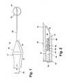
- FIGS. 1 to 3illustrate a marking device 10 according to the invention, which is capable of the percutaneous placement of an imaging marker at a predetermined location, such as a biopsy site or a lesion, within a tissue mass 100.
- the marking device 10comprises an introducer 12 and an imaging marker 14 (FIG. 2) contained within the introducer 12.
- the introducer 12includes a handle 16 having a hollow interior 18 and a rear opening 20.
- the handle 16comprises a grip portion 22 from which extends a tapered nose portion 24.
- the tapered nose portion 24houses a press-fit cannula 30, which defines a lumen 32.
- the cannula 30comprises a proximal end 33 mounted to the handle 16 and a distal end 34 having an expulsion opening 36 spaced from the handle 16.
- the cannula 30has a gage of less than 20, and a 17-gage (0.058 inch outer diameter) cannula, with an inner diameter ranging from 0.049 to 0.051 inches, is most preferred.
- the distal end 34 of the cannula 30can be sharpened to facilitate insertion through the tissue mass 100.
- the distal end 34 of the cannula 30can be designed for enhanced visibility using common imaging techniques, such as radiography, ultrasonography, and magnetic resonance imaging (MRI).
- MRImagnetic resonance imaging
- Suitable cannula tipsare disclosed in U.S. Patent No. 5,490,521, issued February 13, 1996 to R. E. Davis and G. L. McLellan, which is incorporated by reference.
- Ultrasound enhancement technologyis also disclosed in U.S. Patent No. 4,401,124, issued August 30, 1983 to J. F. Guess et al.; and U.S. Patent No. 4,582,061, issued April 15, 1986 to F. J. Fry.
- a stylet 40comprising a base 44 and shaft 42 with a tip 46 is slidably received within the hollow interior 18 of the handle 16 in a manner such that the shaft 42 extends into the cannula lumen 32 and the stylet base 44 lies within the hollow interior 18.
- An actuator in the form of a plunger 50 in operable communication with the stylet base 44comprises a cylindrical body sized so that it is slidably received within the rear opening 20 of the handle 16. Linear displacement of the plunger 50 within the rear opening 20 correspondingly shifts the stylet 40 relative to the handle 16 and the cannula 40.
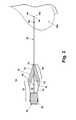
- the stylet 40is movable between a ready position, as best seen in FIG. 2, and an extended position, as illustrated in FIG. 3.
- the tip 46 of the stylet 40is spaced inwardly from the distal end 34 of the cannula 30 to form a marker recess 48 sized to receive the imaging marker 14.
- the tip 46advances towards the distal end 34 to reduce the volume of the marker recess 48 and thereby eject the marker 14 from the marker recess 48.
- the stylet shaft 42be sized in a manner such that when the plunger 50 is in the extended position, the stylet shaft 42 extends beyond the distal end 34 of the cannula 30 to ensure complete ejection of the imaging marker 14 from the marker recess 48. Movement of the plunger 50, which operably engages the stylet base 44, from a first position (FIG. 1) and towards the handle 16 to a second position (FIG. 3) shifts the stylet 40 from the ready position to the extended position.
- a first embodiment of the imaging marker 14comprises a first element 60 and a second element 62 that form a composite body.
- the first element 60has several imaging modes. That is, the first element can be imaged by different imaging techniques. Each imaging mode corresponds to a different imaging technique, including, but not limited to, radiography, such as standard x-ray, mammography, and computerized axial tomography (CAT), ultrasonography, and MRI. However, not all imaging modes have the same efficacy.
- the first element 60is not necessarily easily viewable in each of the imaging modes and could even be substantially indistinguishable from the surrounding tissue in one or more of the imaging modes.
- the first element 60is most readily viewed and easily discernable with a particular imaging technique when located in the tissue mass 100.
- the first element 60can have imaging modes wherein it is viewable with, for example, x-ray, MRI, and ultrasound. If the first element 60 is especially viewable with ultrasound, then, of all the imaging modes, the primary imaging mode for the first element 60 is an ultrasound imaging mode.
- the second element 62has several imaging modes and, in at least one of the imaging modes, which is the primary imaging mode, the second element 62 is most readily viewed and easily discernable with a particular imaging technique when located in the tissue mass 100.
- the second element 62can have imaging modes wherein it is viewable with, for example, x-ray, MRI, and ultrasound. If the second element 62 is especially viewable with x-ray, then, of all the imaging modes, the primary imaging mode for the second element 62 is an x-ray imaging mode. However, the primary imaging mode of the second element 62 is different than the primary imaging mode of the first element 60.
- the imaging marker 14has at least two different primary imaging modes and, therefore, can be readily viewed and distinguished from the surrounding tissue with at least two different imaging techniques. For example, if the first and second elements 60 and 62 have primary imaging modes corresponding to ultrasound and x-ray, respectively, then the subcutaneous imaging marker 14 can be identified with both ultrasound and x-ray imaging techniques.
- the imaging marker 14can optionally comprise other elements in addition to the first and second elements 60 and 62, wherein each of the other elements has its own primary imaging mode.
- the imaging markercan comprise a third element having a third primary imaging mode, a fourth element having a fourth primary imaging mode, and so on.
- the primary imaging mode of each of the other elementscan be unique, can be the same as each other, and can be the same as the first or second primary imaging modes.
- the imaging markercomprises three elements, wherein the first primary imaging mode is ultrasound and the second primary imaging mode is x-ray, the third primary imaging mode can be ultrasound, x-ray, or another imaging mode, such as MRI.
- Each element of the imaging marker 14is considered to be a fundamental constituent thereof.
- An element that is modified to enhance an imaging mode other than its primary imaging modeis considered to constitute more than one element. For example, if a first element having a first primary imaging mode is coated so that it is readily viewed and easily discernable with an imaging technique other than that corresponding to the first imaging mode, then the coating is considered to be a second element with a second primary imaging mode.
- Other examples of modifying elementsinclude adding texture to a surface of an element; immersing an element in a material for impregnation thereof; and blowing air into an element to form pockets or pores of air. In these examples, the texture, the material, and the air are considered to be fundamental constituents of the imaging marker and separate elements having their own primary imaging modes.
- the first element 60is composed of a biocompatible, non-bioabsorbable, and flexible material, preferably polyvinyl alcohol (PVA). Additionally, the first element has a compressible and expandable form, for example, a sponge-like element comprising several small pores (not shown) that undergoes a volumetric change during compression or expansion. When the first element 60 is outside the body, the pores are filled with gas, such as air. In this state, the sponge-like form is easily compressed such that the overall volume of the first element 60 reduces. Conversely, when the first element 60 is introduced into the tissue mass 100, water and other liquids from the tissue enter the pores and thereby swell or expand the first element 60 to a larger volume.
- PVApolyvinyl alcohol
- the preferred primary imaging mode of the first element 60is an ultrasound imaging mode.
- the second element 62is composed of a biocompatible, non-bioabsorbable, and substantially rigid material, preferably a metal, including, but not limited to, titanium and stainless steel. Metals have a significantly lower x-ray transmission relative to soft tissue and, therefore, are clearly distinguishable from surrounding tissue with radiographic imaging techniques, regardless of the orientation of the second element 62. Consequently, the preferred primary imaging mode of the second element 62 is a radiographic imaging mode, such as an x-ray imaging mode. It follows that the imaging marker 14 implanted into the tissue mass 100 can be clearly and consistently viewed with both ultrasonography and radiography, such as x-ray.
- the imaging marker 14can optionally be modified to incorporate another element.
- the first element 60can be soaked in a material, such as iodine or gadolinium, that is viewable with an imaging technique.
- Iodine and gadoliniumare exemplary materials that are known to be viewable with MRI.
- the materialimpregnates the first element 60 and renders the imaging marker 14 viewable with MRI. Consequently, the imaging marker 14 with the first element 60 impregnated with the material comprises a third element, which is the material, having a third primary imaging mode, which is MRI.
- the first element 60is in the shape of an elongated cylinder 64 with an outer diameter
- the second element 62is a clip 66 with a head 68 and a pair of feet 70.
- the head 68 and feet 70are separated by a region 72 where the clip 62 crosses over itself.
- the head 68forms a loop, with an inner diameter, that receives the cylinder 64, and the feet 70 function as anchors to secure the imaging marker 14 within the tissue mass 10 and prevent migration after implantation.
- the cylinder 64can be flexed from a straight configuration, as illustrated in FIG. 4, to a folded condition, as shown in FIG. 2, so that the imaging marker 14 is sized to be received within the lumen 32 of the cannula 30.
- the cylinder 64In the folded condition, the cylinder 64 is bent near its center into somewhat of a U-shape.
- the cylinderis folded substantially in half against the cross region 72 and the feet 70 of the clip 66.
- the ends of the cylinder 64preferably extend beyond the feet 70. Additionally, the feet 70 of the clip 66 can be squeezed together slightly, if necessary, to fit the imaging marker 14 within the lumen 32.
- the outer diameter of the cylinder 64can significantly alter during compression or expansion.
- the first element 64can be compressed, if necessary, to reduce the outer diameter so that it is less than inner diameter of the head 68.
- the first element 64can be compressed to fit the imaging marker 14 within the marker recess 48.
- the outer diameterincreases, preferably to a dimension greater than the inner diameter of the head 68. Because the cylinder 64, in the expanded condition, is larger than the head 68, the head 68 effectively pinches the cylinder 64 near its center, as best viewed in FIG. 6, and the two elements 60 and 62 exert opposing forces upon each other and become embedded. As a result of the embedding, the two elements 60 and 62 form a bond that prevents separation of the cylinder 64 from the clip 66.
- first and second elements 60 and 62for the first embodiment of the imaging marker 14 will now be presented. These dimensions are for illustrative purposes and are not meant to limit the invention in any manner. It is well within the scope of the invention for the dimensions of the first and second elements 60 and 62 to differ from those provided hereinafter provided that the imaging marker is sized to be received within the cannula 30, regardless of the size thereof. As stated above, the cannula 30 is preferably less than 20 gage, and a 17-gage cannula with a 0.049 to 0.051 inch inner diameter is preferred. The cannula 30, however, is not limited to this size, and, thus, the dimensions of the imaging marker 14 shall not be limited in a similar manner.
- the cylinder 64has a length and outer diameter of 0.315 and 0.040 inches, respectively.
- the height of the clip 66is preferably 0.120 inches, and the width of the clip 66 at the feet 70 is 0.055 inches and at the head 68 is 0.045 inches.
- the inner diameter of the head 68is preferably 0.021 inches. It is apparent that, for the imaging marker 14 with the above dimensions, the cylinder 64 of must be compressed for insertion through the head 68 and that expansion of the cylinder 64 to its original size or larger will cause embedding of the first and second elements 60 and 62.
- the above exemplary dimensionsare preferred and are suitable for an imaging marker that can be uses in a hand-held marking device with a 20-gage or less cannula.
- Such hand-held devicesare relatively small and less invasive when compared to other systems, such as the Mammotome® Breast Biopsy System.
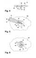
- the introducer 12begins with the stylet 40 in the ready position (FIG. 2) and the plunger 50 in the first position (FIG. 1). With the introducer 12 in this condition, the cannula 30 is positioned so that its distal end 34 is at or near the predetermined location, which is illustrated as a biopsy site 102 in FIGS. 3, 5, and 6, in the tissue mass 100. Preferably, the distal end 34 of the cannula 30 is positioned by using a suitable imaging system.
- the plunger 50is moved from its first position to the second position to displace the stylet 40 from the ready position to the extended position, as shown in FIG. 3.
- the plunger 50drives the stylet base 44 forward to advance the stylet shaft 42 within the lumen 32.
- the tip 46pushes the imaging marker 14 through the marker recess 48 such that the imaging marker 14 extends from the distal end 34 of the cannula, as illustrated in FIG. 5.
- the imaging marker 14is completely ejected from the marker recess 48 and is disposed at the predetermined location within the tissue mass 100.
- the tissue mass 100can resist the advancement of the imaging marker 14.
- PVA in a sponge-like formis relatively weak, thus making it difficult for first element 60 to push through the tissue mass on its own.
- the second element 62is composed of metal, it dominates the resistive forces from the tissue mass 100 and delivers the first element 60 to the predetermined location.
- the cross region 72 of the clip 66pulls the cylinder 64, which is in the folded condition, along with the clip 66 to the predetermined location.
- the cylinder 64upon ejection, unfolds and expands as it absorbs liquid from the tissue mass 100.
- the degree to which the cylinder 64 unfoldsis governed by the geometry and structure of the predetermined location. If the predetermined location is a biopsy site 102 having a dimension larger than the length of the cylinder 64, then typically the cylinder 64 will unfold until it becomes constrained by the cavity walls of the biopsy site 102. Upon expansion, the cylinder 64 and the head 68 become embedded, thereby securing the first and second elements 60 and 62 together. Additionally, the feet 70 anchor the imaging marker 14 to the predetermined location to prevent migration of the imaging marker 14 within the tissue mass 100.
- the subcutaneous imaging marker 14is easily viewed in either of the primary imaging modes of the first and second elements 60 and 62.
- a practitionercan identify the imaging marker 14 and, therefore, pinpoint the predetermined location using either ultrasound, which is the primary imaging mode of the first element 60, or x-ray, which is the primary imaging mode of the second element 62.
- ultrasoundwhich is the primary imaging mode of the first element 60
- x-raywhich is the primary imaging mode of the second element 62.
- FIGS. 7-10Alternative embodiments of the imaging marker 14 according to the invention are illustrated in FIGS. 7-10 where similar components are identified with the same reference numeral bearing a prime (') symbol.
- the alternative embodimentsare substantially the same as the first embodiment, with the primary difference being the form of the second element 62 and the manner in which it is coupled to the first element 60.
- an imaging marker 14'comprise a first element 60' and a second element 62'.
- the second element 62'is preferably a clip 66' with a head 68' and a pair of feet 70' separated by a cross region 72'.
- the first element 60'comprises various forms, as depicted in FIGS. 7-10. Regardless of the form of the first element 60', at least a portion of each of the first and second elements 60' and 62' are embedded to secure the elements 60' and 62' together to form a composite body.
- the first element 60'is in the form of two cylinders 64' mounted onto the feet 70' of the clip 66'.
- an adhesivesuch as an ultraviolet (UV) curable adhesive, facilitates the mounting the cylinders 64'.
- UV curable adhesiveis a cyanoacrylate adhesive.
- the head 68' of the second embodimentfunctions as an anchor to prevent migration of the imaging marker 14'.
- the first element 60' of third and fourth embodimentswhich are illustrated in FIGS. 8 and 9, is in the form of a block 80.
- the head 68' of the clip 66'is embedded within the block 80, while the entire clip 66' is embedded in the block 80 in the fourth embodiment.
- the clip 66'is also completely embedded within the first element 60', but the first element 60' is in the form of a cylinder 64'.
- FIGS. 7-10are ejected from the marker recess 48 of the marking device 10 and into the predetermined location within the tissue mass 100 in the same manner as the first embodiment.
- the imaging markers 14'can be clearly viewed and distinguished from the surrounding tissue with imaging techniques corresponding to the primary imaging modes of the first and second elements 60' and 62'.
- the imaging markeris described above as comprising two non-bioabsorbable elements, each with a different primary imaging mode, the invention shall not be limited to comprising only two non-bioabsorbable elements. It is within the scope of the invention for the imaging marker to comprise more than two non-bioabsorbable elements, each with a different primary imaging mode. Further, each non-bioabsorbable element can have more than one primary imaging mode provided that one of the primary imaging modes is different from the primary imaging mode(s) of the other element(s). For example, if the second element is comprised of a non-magnetic metal, such as titanium, and can be viewed with MRI as well as with x-ray, then the second element could have two primary imaging modes.
- a non-magnetic metalsuch as titanium
- the first elementis the form of a cylinder or block, and the second element is shown as a clip; however, the first and second elements can be of any suitable shape that can be received within the cannula and implanted into a tissue mass.
- the imaging markeris not limited to use with the marking device detailed above. The imaging marker can be implanted with a device that is not self-contained or with a self-contained marking device other than that described herein.
- the imaging marker according to the inventioncan be easily viewed and readily distinguished from the surrounding tissue with more than one medical imaging technique. Because a practitioner is not limited to locating the imaging marker with only one technique, he or she has the flexibility of being able to select the imaging technique most suitable, both physically and financially, for the patient. Furthermore, the non-bioabsorbable imaging marker is securely embedded together and anchored to the predetermined location to provide a reliable and enduring marker for the predetermined location.
Landscapes
- Health & Medical Sciences (AREA)
- Surgery (AREA)
- Life Sciences & Earth Sciences (AREA)
- Heart & Thoracic Surgery (AREA)
- Molecular Biology (AREA)
- Oral & Maxillofacial Surgery (AREA)
- Engineering & Computer Science (AREA)
- Biomedical Technology (AREA)
- Nuclear Medicine, Radiotherapy & Molecular Imaging (AREA)
- Medical Informatics (AREA)
- Pathology (AREA)
- Animal Behavior & Ethology (AREA)
- General Health & Medical Sciences (AREA)
- Public Health (AREA)
- Veterinary Medicine (AREA)
- Magnetic Resonance Imaging Apparatus (AREA)
- Prostheses (AREA)
- Apparatus For Radiation Diagnosis (AREA)
Abstract
Description
Claims (30)
- A non-bioabsorbable imaging marker for the subcutaneous marking oftissue, the non-bioabsorbable imaging marker comprising:wherein the second primary imaging mode is different than the first primaryimaging mode.a first primary imaging mode anda second primary imaging mode,
- The non-bioabsorbable imaging marker according to claim 1 and furthercomprising a first element having the first primary imaging mode and a second elementhaving the second primary imaging mode.
- The non-bioabsorbable imaging marker according to claims 1 or 2 whereinthe first element is expandable in volume.
- The non-bioabsorbable imaging marker according to claims 2 or 3 whereinthe first element is made from PVA.
- The non-bioabsorbable imaging marker according to any of claims 2 - 4wherein the second element is made of metal.
- The non-bioabsorbable imaging marker according to any of claims 2 - 5wherein at least a portion of one of the first and second elements is embedded in the otherof the first and second elements.
- The non-bioabsorbable imaging marker according to any of claims 2 - 6wherein one of the first and second elements is completely embedded in the other of thefirst and second elements.
- The non-bioabsorbable imaging marker according to any of claims 2 - 7wherein the second element comprises a loop that surrounds the first element.
- The non-bioabsorbable imaging marker according to any of claims 2 - 8wherein the second element comprises a body with a foot.
- The non-bioabsorbable imaging marker according to claim 9 wherein thebody is embedded within the first element.
- The non-bioabsorbable imaging marker according to claims 9 or 10 whereinthe foot is embedded within the first element.
- The non-bioabsorbable imaging marker according to any of claims 9 - 11wherein the foot forms an anchor.
- The non-bioabsorbable imaging marker according to any of claims 9 - 12wherein the body comprises a loop surrounding the first element.
- The non-bioabsorbable imaging marker according to claim 13 wherein theloop has an inner diameter and the first element has an outer diameter, wherein the firstelement can expand so that the outer diameter is greater than the inner diameter to effectembedding of one of the first and second elements in the other of the first and secondelements.
- The non-bioabsorbable imaging marker according to claim 14 wherein theinner diameter is between 0.010 and 0.030 inches.
- The non-bioabsorbable imaging marker according to claims 14 or 15wherein the outer diameter can be expanded to approximately twice the inner diameter.
- The non-bioabsorbable imaging marker according to any of claims 9 - 16wherein the first element can be folded against the foot so that the non-bioabsorbableimaging marker is sized to be received within a hollow needle having a gage of less than20.
- The non-bioabsorbable imaging marker according to any of claims 2 - 17wherein the first element can be compressed to size the non-bioabsorbable imaging markerfor receipt within the hollow needle.
- The non-bioabsorbable imaging marker according to any of claims 2 - 18and further comprising at least one additional element, wherein each additional element hasa primary imaging mode.
- The non-bioabsorbable imaging marker according to any of claims 1 - 19wherein the first primary imaging mode is one of ultrasound, x-ray, CAT, and MRI.
- The non-bioabsorbable imaging marker according to any of claims 1 - 20wherein the second primary imaging mode is one of ultrasound, x-ray, CAT and MRI.
- The non-bioabsorbable imaging marker according to any of claims 1 - 21wherein one of the first and second primary imaging modes is ultrasound and the other ofthe first and second primary imaging modes is x-ray.
- The non-bioabsorbable imaging marker according to any of claims 1 - 22and further comprising at least one additional primary imaging mode.
- The non-bioabsorbable imaging marker according to any of claims 1 - 23and in combination with an implanting device for implanting the non-bioabsorbableimaging marker.
- The non-bioabsorbabie imaging marker according to claim 24, wherein theimplanting device comprises:wherein movement of the stylet from the ready position to the extendedposition thereby ejects the non-bioabsorbable imaging marker from the marker recessthrough the expulsion opening.a cannula defining a lumen and having a distal end and an expulsionopening near the distal end; anda stylet slidably received within the lumen for movement between a readyposition in which a tip of the stylet is spaced inwardly from the distal end to form a markerrecess therebetween for receiving the non-bioabsorbable imaging marker, and an extendedposition in which the tip of the stylet is advanced toward the distal end; and
- The non-bioabsorbable imaging marker according to claim 25 wherein theimplanting device further comprises a handle to be grasped by a user, and the cannulahaving a proximal end mounted to the handle.
- The non-bioabsorbable imaging marker according to any of claims 24 - 26wherein the implanting device further comprises an actuator for moving the stylet relativeto the cannula.
- The non-bioabsorbable imaging marker according to claim 27 wherein theactuator is mounted to the handle.
- The non-bioabsorbable imaging marker according to any of claims 25 - 28wherein the actuator is a plunger movable between a first position and a second position formoving the stylet between the ready position and the extended position.
- The non-bioabsorbable imaging marker according to any of claims 25 - 29wherein the cannula, the stylet, the actuator, and the handle form an introducer, and theintroducer and the non-bioabsorbable imaging marker form a self-contained markingdevice that can be easily and conveniently handled by a user to place the non-bioabsorbableimaging marker at a predetermined location in a tissue mass by the user moving theplunger between the first and second positions to move the stylet from the ready to theextended position to thereby eject the non-bioabsorbable imaging marker from the markerrecess after the cannula is inserted into the tissue mass and the insertion tip is located at thepredetermined location.
Priority Applications (1)
| Application Number | Priority Date | Filing Date | Title |
|---|---|---|---|
| EP19166774.0AEP3524203A3 (en) | 2004-06-04 | 2005-05-31 | Multi-mode imaging marker |
Applications Claiming Priority (2)
| Application Number | Priority Date | Filing Date | Title |
|---|---|---|---|
| US10/709,899US20050273002A1 (en) | 2004-06-04 | 2004-06-04 | Multi-mode imaging marker |
| US709899 | 2004-06-04 |
Related Child Applications (2)
| Application Number | Title | Priority Date | Filing Date |
|---|---|---|---|
| EP19166774.0ADivisionEP3524203A3 (en) | 2004-06-04 | 2005-05-31 | Multi-mode imaging marker |
| EP19166774.0ADivision-IntoEP3524203A3 (en) | 2004-06-04 | 2005-05-31 | Multi-mode imaging marker |
Publications (2)
| Publication Number | Publication Date |
|---|---|
| EP1602341A1true EP1602341A1 (en) | 2005-12-07 |
| EP1602341B1 EP1602341B1 (en) | 2020-01-15 |
Family
ID=34937107
Family Applications (2)
| Application Number | Title | Priority Date | Filing Date |
|---|---|---|---|
| EP19166774.0AWithdrawnEP3524203A3 (en) | 2004-06-04 | 2005-05-31 | Multi-mode imaging marker |
| EP05011761.3AExpired - LifetimeEP1602341B1 (en) | 2004-06-04 | 2005-05-31 | Multi-mode imaging marker |
Family Applications Before (1)
| Application Number | Title | Priority Date | Filing Date |
|---|---|---|---|
| EP19166774.0AWithdrawnEP3524203A3 (en) | 2004-06-04 | 2005-05-31 | Multi-mode imaging marker |
Country Status (3)
| Country | Link |
|---|---|
| US (2) | US20050273002A1 (en) |
| EP (2) | EP3524203A3 (en) |
| CA (1) | CA2508982C (en) |
Cited By (5)
| Publication number | Priority date | Publication date | Assignee | Title |
|---|---|---|---|---|
| WO2009149229A1 (en)* | 2008-06-04 | 2009-12-10 | Suros Surgical Systems, Inc. | Site marker visible under multiple modalities |
| US8060183B2 (en) | 2004-10-13 | 2011-11-15 | Suros Surgical Systems, Inc. | Site marker visible under multiple modalities |
| US8280486B2 (en) | 2004-10-13 | 2012-10-02 | Suros Surgical Systems, Inc. | Site marker visable under multiple modalities |
| US8433391B2 (en) | 2004-10-13 | 2013-04-30 | Suros Surgical Systems, Inc. | Site marker |
| WO2019011801A1 (en)* | 2017-07-11 | 2019-01-17 | Bip Biomed. Instrumente & Produkte Gmbh | MEDICAL, IMPLANTABLE MARKER AND DEVICE FOR IMPLANTING THE MARKER |
Families Citing this family (48)
| Publication number | Priority date | Publication date | Assignee | Title |
|---|---|---|---|---|
| US8668737B2 (en) | 1997-10-10 | 2014-03-11 | Senorx, Inc. | Tissue marking implant |
| US7637948B2 (en) | 1997-10-10 | 2009-12-29 | Senorx, Inc. | Tissue marking implant |
| US8498693B2 (en) | 1999-02-02 | 2013-07-30 | Senorx, Inc. | Intracorporeal marker and marker delivery device |
| US8361082B2 (en) | 1999-02-02 | 2013-01-29 | Senorx, Inc. | Marker delivery device with releasable plug |
| US6862470B2 (en) | 1999-02-02 | 2005-03-01 | Senorx, Inc. | Cavity-filling biopsy site markers |
| US6725083B1 (en) | 1999-02-02 | 2004-04-20 | Senorx, Inc. | Tissue site markers for in VIVO imaging |
| US7983734B2 (en) | 2003-05-23 | 2011-07-19 | Senorx, Inc. | Fibrous marker and intracorporeal delivery thereof |
| US20090030309A1 (en) | 2007-07-26 | 2009-01-29 | Senorx, Inc. | Deployment of polysaccharide markers |
| US9820824B2 (en) | 1999-02-02 | 2017-11-21 | Senorx, Inc. | Deployment of polysaccharide markers for treating a site within a patent |
| US7651505B2 (en) | 2002-06-17 | 2010-01-26 | Senorx, Inc. | Plugged tip delivery for marker placement |
| US6575991B1 (en) | 1999-06-17 | 2003-06-10 | Inrad, Inc. | Apparatus for the percutaneous marking of a lesion |
| CA2659518A1 (en) | 2000-11-20 | 2002-05-30 | Senorx, Inc. | Tissue site markers for in vivo imaging |
| US20060036158A1 (en) | 2003-11-17 | 2006-02-16 | Inrad, Inc. | Self-contained, self-piercing, side-expelling marking apparatus |
| US7877133B2 (en) | 2003-05-23 | 2011-01-25 | Senorx, Inc. | Marker or filler forming fluid |
| US20050273002A1 (en)* | 2004-06-04 | 2005-12-08 | Goosen Ryan L | Multi-mode imaging marker |
| US20090216115A1 (en)* | 2004-07-23 | 2009-08-27 | Calypso Medical Technologies, Inc. | Anchoring wirless markers within a human body |
| US8419656B2 (en) | 2004-11-22 | 2013-04-16 | Bard Peripheral Vascular, Inc. | Post decompression marker introducer system |
| US10357328B2 (en) | 2005-04-20 | 2019-07-23 | Bard Peripheral Vascular, Inc. and Bard Shannon Limited | Marking device with retractable cannula |
| US8052658B2 (en) | 2005-10-07 | 2011-11-08 | Bard Peripheral Vascular, Inc. | Drug-eluting tissue marker |
| WO2007061890A2 (en) | 2005-11-17 | 2007-05-31 | Calypso Medical Technologies, Inc. | Apparatus and methods for using an electromagnetic transponder in orthopedic procedures |
| DE102006024245A1 (en)* | 2006-05-23 | 2007-08-02 | Siemens Ag | Medical instrument and method for localizing it in the human body |
| EP2041960A2 (en)* | 2006-07-05 | 2009-04-01 | Koninklijke Philips Electronics N.V. | Enhanced "ticker" application |
| SE0601472L (en)* | 2006-07-05 | 2008-01-06 | Anders Widmark | Reference agencies |
| US20080033286A1 (en)* | 2006-08-02 | 2008-02-07 | Civco Medical Instruments Co., Inc. | Fiducial marker for imaging localization and method of using the same |
| WO2008051749A2 (en) | 2006-10-23 | 2008-05-02 | C. R. Bard, Inc. | Breast marker |
| US9579077B2 (en) | 2006-12-12 | 2017-02-28 | C.R. Bard, Inc. | Multiple imaging mode tissue marker |
| WO2008076973A2 (en) | 2006-12-18 | 2008-06-26 | C.R.Bard Inc. | Biopsy marker with in situ-generated imaging properties |
| US20080234572A1 (en)* | 2007-03-23 | 2008-09-25 | Civco Medical Instruments Co., Inc. | Fiducial marker with absorbable connecting sleeve and absorbable spacer for imaging localization |
| WO2009099767A2 (en) | 2008-01-31 | 2009-08-13 | C.R. Bard, Inc. | Biopsy tissue marker |
| CN102056544B (en)* | 2008-06-13 | 2017-04-12 | 皇家飞利浦电子股份有限公司 | Multimodal imaging fiducial marker |
| US9327061B2 (en) | 2008-09-23 | 2016-05-03 | Senorx, Inc. | Porous bioabsorbable implant |
| EP4215147A3 (en) | 2008-12-30 | 2023-10-18 | C. R. Bard, Inc. | Marker delivery device for tissue marker placement |
| US9943704B1 (en) | 2009-01-21 | 2018-04-17 | Varian Medical Systems, Inc. | Method and system for fiducials contained in removable device for radiation therapy |
| US9936892B1 (en)* | 2009-05-04 | 2018-04-10 | Cortex Manufacturing Inc. | Systems and methods for providing a fiducial marker |
| US20110028831A1 (en)* | 2009-07-30 | 2011-02-03 | Kent James P | Permanently visible implantable fiduciary tissue marker |
| EP2945543B1 (en)* | 2013-01-18 | 2021-03-10 | The Johns Hopkins University | Ultrasound-detectable markers |
| US9119650B2 (en) | 2013-03-15 | 2015-09-01 | Covidien Lp | Microwave energy-delivery device and system |
| US9161814B2 (en)* | 2013-03-15 | 2015-10-20 | Covidien Lp | Microwave energy-delivery device and system |
| US9301723B2 (en) | 2013-03-15 | 2016-04-05 | Covidien Lp | Microwave energy-delivery device and system |
| USD715942S1 (en) | 2013-09-24 | 2014-10-21 | C. R. Bard, Inc. | Tissue marker for intracorporeal site identification |
| USD715442S1 (en) | 2013-09-24 | 2014-10-14 | C. R. Bard, Inc. | Tissue marker for intracorporeal site identification |
| USD716450S1 (en) | 2013-09-24 | 2014-10-28 | C. R. Bard, Inc. | Tissue marker for intracorporeal site identification |
| USD716451S1 (en) | 2013-09-24 | 2014-10-28 | C. R. Bard, Inc. | Tissue marker for intracorporeal site identification |
| US10624697B2 (en) | 2014-08-26 | 2020-04-21 | Covidien Lp | Microwave ablation system |
| US10813692B2 (en) | 2016-02-29 | 2020-10-27 | Covidien Lp | 90-degree interlocking geometry for introducer for facilitating deployment of microwave radiating catheter |
| US11446114B2 (en)* | 2020-01-21 | 2022-09-20 | Med-Genesis, Llc | Biopsy marker with anchoring capabilities |
| US10842591B1 (en)* | 2020-01-21 | 2020-11-24 | Med-Genesis, Llc | Biopsy marker with anchoring capabilities |
| JP7739321B2 (en)* | 2020-03-17 | 2025-09-16 | デビコー・メディカル・プロダクツ・インコーポレイテッド | Biopsy site marker with non-moving features |
Citations (5)
| Publication number | Priority date | Publication date | Assignee | Title |
|---|---|---|---|---|
| WO2001008578A1 (en)* | 1999-07-30 | 2001-02-08 | Vivant Medical, Inc. | Device and method for safe location and marking of a cavity and sentinel lymph nodes |
| WO2002041786A2 (en) | 2000-11-20 | 2002-05-30 | Senorx, Inc. | Tissue site markers for in vivo imaging |
| US20020151797A1 (en)* | 2000-10-23 | 2002-10-17 | Valentino Montegrande | Ultrasound imaging marker and method of use |
| US20020188196A1 (en)* | 1999-02-02 | 2002-12-12 | Burbank Fred H. | Cavity-filling biopsy site markers |
| WO2004045444A2 (en) | 2002-11-18 | 2004-06-03 | Inrad, Inc. | Tissue localizing and marking device and method of using same |
Family Cites Families (460)
| Publication number | Priority date | Publication date | Assignee | Title |
|---|---|---|---|---|
| US2899362A (en) | 1959-08-11 | Hemostatic sponges and method of | ||
| GB708148A (en) | 1950-12-18 | 1954-04-28 | Hoechst Ag | Hemostatic preparations and process for the manufacture thereof |
| DE1029528B (en) | 1954-01-30 | 1958-05-08 | Med H C Ernst Pohl Dr | Device for marking a drill hole to be made, especially for bone nails and bone screws |
| US2907327A (en) | 1957-02-08 | 1959-10-06 | Pfizer & Co C | Pellet implanter |
| US3516412A (en) | 1965-08-16 | 1970-06-23 | Electro Catheter Corp | Bipolar electrode having irregularity at inserting end thereof and method of insertion |
| US3402712A (en) | 1966-07-19 | 1968-09-24 | American Home Prod | Pellet implanter |
| US3823212A (en) | 1968-11-27 | 1974-07-09 | Freudenberg C Fa | Process for the production of collagen fiber fabrics in the form of felt-like membranes or sponge-like layers |
| CS151338B1 (en) | 1971-01-22 | 1973-10-19 | ||
| US3921632A (en) | 1974-08-16 | 1975-11-25 | Frank M Bardani | Implant device |
| US4197846A (en) | 1974-10-09 | 1980-04-15 | Louis Bucalo | Method for structure for situating in a living body agents for treating the body |
| US4005699A (en) | 1974-10-09 | 1977-02-01 | Louis Bucalo | Methods and apparatus for use in magnetic treatment of the body |
| US4007732A (en) | 1975-09-02 | 1977-02-15 | Robert Carl Kvavle | Method for location and removal of soft tissue in human biopsy operations |
| US4041931A (en) | 1976-05-17 | 1977-08-16 | Elliott Donald P | Radiopaque anastomosis marker |
| US4217889A (en) | 1976-09-15 | 1980-08-19 | Heyer-Schulte Corporation | Flap development device and method of progressively increasing skin area |
| US4105030A (en) | 1977-01-03 | 1978-08-08 | Syntex (U.S.A.) Inc. | Implant apparatus |
| US4103690A (en) | 1977-03-21 | 1978-08-01 | Cordis Corporation | Self-suturing cardiac pacer lead |
| US4294241A (en) | 1977-06-09 | 1981-10-13 | Teruo Miyata | Collagen skin dressing |
| US4588395A (en) | 1978-03-10 | 1986-05-13 | Lemelson Jerome H | Catheter and method |
| US4172449A (en) | 1978-05-01 | 1979-10-30 | New Research And Development Laboratories, Inc. | Body fluid pressure monitor |
| US4276885A (en) | 1979-05-04 | 1981-07-07 | Rasor Associates, Inc | Ultrasonic image enhancement |
| US4331654A (en) | 1980-06-13 | 1982-05-25 | Eli Lilly And Company | Magnetically-localizable, biodegradable lipid microspheres |
| US4390018A (en) | 1980-09-15 | 1983-06-28 | Zukowski Henry J | Method for preventing loss of spinal fluid after spinal tap |
| US4442843A (en) | 1980-11-17 | 1984-04-17 | Schering, Ag | Microbubble precursors and methods for their production and use |
| US4470160A (en) | 1980-11-21 | 1984-09-11 | Cavon Joseph F | Cast gel implantable prosthesis |
| US4740208A (en) | 1980-11-21 | 1988-04-26 | Cavon Joseph F | Cast gel implantable prosthesis |
| US4298998A (en) | 1980-12-08 | 1981-11-10 | Naficy Sadeque S | Breast prosthesis with biologically absorbable outer container |
| US4428082A (en) | 1980-12-08 | 1984-01-31 | Naficy Sadeque S | Breast prosthesis with filling valve |
| US4487209A (en) | 1981-03-16 | 1984-12-11 | Creative Research And Manufacturing Inc. | Biopsy needle |
| US4401124A (en) | 1981-08-13 | 1983-08-30 | Technicare Corporation | Reflection enhancement of a biopsy needle |
| US4400170A (en) | 1981-09-29 | 1983-08-23 | Syntex (U.S.A.) Inc. | Implanting device and implant magazine |
| US4582061A (en) | 1981-11-18 | 1986-04-15 | Indianapolis Center For Advanced Research, Inc. | Needle with ultrasonically reflective displacement scale |
| US4582640A (en) | 1982-03-08 | 1986-04-15 | Collagen Corporation | Injectable cross-linked collagen implant material |
| US4405314A (en) | 1982-04-19 | 1983-09-20 | Cook Incorporated | Apparatus and method for catheterization permitting use of a smaller gage needle |
| US4545367A (en) | 1982-07-16 | 1985-10-08 | Cordis Corporation | Detachable balloon catheter and method of use |
| US5542915A (en) | 1992-08-12 | 1996-08-06 | Vidamed, Inc. | Thermal mapping catheter with ultrasound probe |
| US4438253A (en) | 1982-11-12 | 1984-03-20 | American Cyanamid Company | Poly(glycolic acid)/poly(alkylene glycol) block copolymers and method of manufacturing the same |
| GB2138298B (en) | 1983-04-21 | 1986-11-05 | Hundon Forge Ltd | Pellet implanter |
| US4647480A (en) | 1983-07-25 | 1987-03-03 | Amchem Products, Inc. | Use of additive in aqueous cure of autodeposited coatings |
| US4655226A (en) | 1983-12-16 | 1987-04-07 | Southland Instruments, Inc. | Disposable biopsy needle unit |
| CH661199A5 (en) | 1983-12-22 | 1987-07-15 | Sulzer Ag | MARKING IMPLANT. |
| US4549560A (en) | 1984-03-19 | 1985-10-29 | Andis Company | Hair curling appliance with elastomer material covering heating element |
| MX163953B (en) | 1984-03-27 | 1992-07-03 | Univ New Jersey Med | PROCEDURE FOR PREPARING A BIODEGRADABLE COLLAGEN MATRIX |
| US4963150B1 (en) | 1984-08-30 | 1994-10-04 | Daniel Brauman | Implantable prosthetic device |
| US4648880A (en) | 1984-08-30 | 1987-03-10 | Daniel Brauman | Implantable prosthetic devices |
| US4820267A (en) | 1985-02-19 | 1989-04-11 | Endocon, Inc. | Cartridge injector for pellet medicaments |
| US4863470A (en) | 1985-03-19 | 1989-09-05 | Medical Engineering Corporation | Identification marker for a breast prosthesis |
| US5628781A (en) | 1985-06-06 | 1997-05-13 | Thomas Jefferson University | Implant materials, methods of treating the surface of implants with microvascular endothelial cells, and the treated implants themselves |
| US4847049A (en) | 1985-12-18 | 1989-07-11 | Vitaphore Corporation | Method of forming chelated collagen having bactericidal properties |
| US4693237A (en) | 1986-01-21 | 1987-09-15 | Hoffman Richard B | Radiopaque coded ring markers for use in identifying surgical grafts |
| US4682606A (en) | 1986-02-03 | 1987-07-28 | Decaprio Vincent H | Localizing biopsy apparatus |
| US4661103A (en) | 1986-03-03 | 1987-04-28 | Engineering Development Associates, Ltd. | Multiple implant injector |
| US4832686A (en) | 1986-06-24 | 1989-05-23 | Anderson Mark E | Method for administering interleukin-2 |
| US4832680A (en) | 1986-07-03 | 1989-05-23 | C.R. Bard, Inc. | Apparatus for hypodermically implanting a genitourinary prosthesis |
| DE3789320T2 (en) | 1986-07-30 | 1994-06-09 | Sumitomo Pharma | Administration instrument for the introduction of solid medication. |
| US4813062A (en) | 1986-08-13 | 1989-03-14 | Milliken Research Corporation | Radio-opaque marker and method |
| US4762128A (en) | 1986-12-09 | 1988-08-09 | Advanced Surgical Intervention, Inc. | Method and apparatus for treating hypertrophy of the prostate gland |
| US4994028A (en) | 1987-03-18 | 1991-02-19 | Endocon, Inc. | Injector for inplanting multiple pellet medicaments |
| US4874376A (en) | 1987-04-13 | 1989-10-17 | Hawkins Jr Irvin F | Needle guide assembly |
| EP0292936B1 (en) | 1987-05-26 | 1996-03-06 | Sumitomo Pharmaceuticals Company, Limited | Device for administering solid preparations |
| US4989608A (en) | 1987-07-02 | 1991-02-05 | Ratner Adam V | Device construction and method facilitating magnetic resonance imaging of foreign objects in a body |
| US5120802A (en) | 1987-12-17 | 1992-06-09 | Allied-Signal Inc. | Polycarbonate-based block copolymers and devices |
| US4889707A (en) | 1988-01-29 | 1989-12-26 | The Curators Of The University Of Missouri | Composition and method for radiation synovectomy of arthritic joints |
| US4870966A (en) | 1988-02-01 | 1989-10-03 | American Cyanamid Company | Bioabsorbable surgical device for treating nerve defects |
| AU635200B2 (en) | 1988-02-05 | 1993-03-18 | Schering Aktiengesellschaft Berlin Und Bergkamen | Ultrasonic contrast agents, process for producing them and their use as diagnostic and therapeutic agents |
| US5425366A (en) | 1988-02-05 | 1995-06-20 | Schering Aktiengesellschaft | Ultrasonic contrast agents for color Doppler imaging |
| US5374261A (en) | 1990-07-24 | 1994-12-20 | Yoon; Inbae | Multifunctional devices for use in endoscopic surgical procedures and methods-therefor |
| US4994013A (en) | 1988-07-28 | 1991-02-19 | Best Industries, Inc. | Pellet for a radioactive seed |
| US4938763B1 (en) | 1988-10-03 | 1995-07-04 | Atrix Lab Inc | Biodegradable in-situ forming implants and method of producing the same |
| US5702716A (en) | 1988-10-03 | 1997-12-30 | Atrix Laboratories, Inc. | Polymeric compositions useful as controlled release implants |
| US4950665A (en) | 1988-10-28 | 1990-08-21 | Oklahoma Medical Research Foundation | Phototherapy using methylene blue |
| US4909250A (en) | 1988-11-14 | 1990-03-20 | Smith Joseph R | Implant system for animal identification |
| US5800541A (en) | 1988-11-21 | 1998-09-01 | Collagen Corporation | Collagen-synthetic polymer matrices prepared using a multiple step reaction |
| US5475052A (en) | 1988-11-21 | 1995-12-12 | Collagen Corporation | Collagen-synthetic polymer matrices prepared using a multiple step reaction |
| US5162430A (en) | 1988-11-21 | 1992-11-10 | Collagen Corporation | Collagen-polymer conjugates |
| WO1990009152A1 (en) | 1989-02-15 | 1990-08-23 | Microtek Medical, Inc. | Biocompatible material and prosthesis |
| US5141748A (en) | 1989-02-17 | 1992-08-25 | Hoffmann-La Roche, Inc. | Implant drug delivery device |
| US5201314A (en) | 1989-03-09 | 1993-04-13 | Vance Products Incorporated | Echogenic devices, material and method |
| US5081997A (en) | 1989-03-09 | 1992-01-21 | Vance Products Incorporated | Echogenic devices, material and method |
| US5289831A (en) | 1989-03-09 | 1994-03-01 | Vance Products Incorporated | Surface-treated stent, catheter, cannula, and the like |
| US5025797A (en) | 1989-03-29 | 1991-06-25 | Baran Gregory W | Automated biopsy instrument |
| GB2230191B (en) | 1989-04-15 | 1992-04-22 | Robert Graham Urie | Lesion location device |
| DE8905585U1 (en) | 1989-05-03 | 1989-06-29 | Bosch-Siemens Hausgeräte GmbH, 8000 München | Storage and dosing device for storing pumpable detergent or dishwashing detergent ingredients |
| US5012818A (en) | 1989-05-04 | 1991-05-07 | Joishy Suresh K | Two in one bone marrow surgical needle |
| US5197482A (en) | 1989-06-15 | 1993-03-30 | Research Corporation Technologies, Inc. | Helical-tipped lesion localization needle device and method of using the same |
| US5018530A (en) | 1989-06-15 | 1991-05-28 | Research Corporation Technologies, Inc. | Helical-tipped lesion localization needle device and method of using the same |
| US5284479A (en) | 1989-08-30 | 1994-02-08 | N.V. Nederlandsche Apparatenfabriek Nedap | Implanter |
| US5271961A (en) | 1989-11-06 | 1993-12-21 | Alkermes Controlled Therapeutics, Inc. | Method for producing protein microspheres |
| JPH03158171A (en) | 1989-11-17 | 1991-07-08 | Masataka Saito | Cap integral type disposal injection needle |
| US5197846A (en) | 1989-12-22 | 1993-03-30 | Hitachi, Ltd. | Six-degree-of-freedom articulated robot mechanism and assembling and working apparatus using same |
| US5334381A (en) | 1989-12-22 | 1994-08-02 | Unger Evan C | Liposomes as contrast agents for ultrasonic imaging and methods for preparing the same |
| US5585112A (en) | 1989-12-22 | 1996-12-17 | Imarx Pharmaceutical Corp. | Method of preparing gas and gaseous precursor-filled microspheres |
| GB9003821D0 (en) | 1990-02-20 | 1990-04-18 | Danbiosyst Uk | Diagnostic aid |
| JPH042372U (en) | 1990-04-23 | 1992-01-09 | ||
| US5137928A (en) | 1990-04-26 | 1992-08-11 | Hoechst Aktiengesellschaft | Ultrasonic contrast agents, processes for their preparation and the use thereof as diagnostic and therapeutic agents |
| AU636481B2 (en) | 1990-05-18 | 1993-04-29 | Bracco International B.V. | Polymeric gas or air filled microballoons usable as suspensions in liquid carriers for ultrasonic echography |
| US5236410A (en) | 1990-08-02 | 1993-08-17 | Ferrotherm International, Inc. | Tumor treatment method |
| EP0475077B1 (en) | 1990-09-10 | 1996-06-12 | Synthes AG, Chur | Bone regeneration membrane |
| US5353804A (en) | 1990-09-18 | 1994-10-11 | Peb Biopsy Corporation | Method and device for percutaneous exisional breast biopsy |
| US5391183A (en) | 1990-09-21 | 1995-02-21 | Datascope Investment Corp | Device and method sealing puncture wounds |
| US5221269A (en) | 1990-10-15 | 1993-06-22 | Cook Incorporated | Guide for localizing a nonpalpable breast lesion |
| US6347240B1 (en) | 1990-10-19 | 2002-02-12 | St. Louis University | System and method for use in displaying images of a body part |
| US5282781A (en) | 1990-10-25 | 1994-02-01 | Omnitron International Inc. | Source wire for localized radiation treatment of tumors |
| US5370901A (en) | 1991-02-15 | 1994-12-06 | Bracco International B.V. | Compositions for increasing the image contrast in diagnostic investigations of the digestive tract of patients |
| US5280788A (en) | 1991-02-26 | 1994-01-25 | Massachusetts Institute Of Technology | Devices and methods for optical diagnosis of tissue |
| WO1992015362A1 (en) | 1991-03-06 | 1992-09-17 | Süddeutsche Feinmechanik GmbH | Needle for inserting an object into the body |
| JP3007903B2 (en)* | 1991-03-29 | 2000-02-14 | 京セラ株式会社 | Artificial disc |
| US5205290A (en) | 1991-04-05 | 1993-04-27 | Unger Evan C | Low density microspheres and their use as contrast agents for computed tomography |
| US5147631A (en) | 1991-04-30 | 1992-09-15 | Du Pont Merck Pharmaceutical Company | Porous inorganic ultrasound contrast agents |
| US5354623A (en) | 1991-05-21 | 1994-10-11 | Cook Incorporated | Joint, a laminate, and a method of preparing a nickel-titanium alloy member surface for bonding to another layer of metal |
| US5242759A (en) | 1991-05-21 | 1993-09-07 | Cook Incorporated | Joint, a laminate, and a method of preparing a nickel-titanium alloy member surface for bonding to another layer of metal |
| US5147307A (en) | 1991-06-17 | 1992-09-15 | Gluck Seymour M | Anatomical marker device and method |
| US5449560A (en) | 1991-07-05 | 1995-09-12 | Dow Corning S.A. | Composition suitable for glass laminate interlayer and laminate made therefrom |
| FI940028A7 (en) | 1991-07-05 | 1994-02-25 | Univ Rochester | Ultra-small, non-aggregated porous particles enclosing gas bubbles |
| US5195540A (en) | 1991-08-12 | 1993-03-23 | Samuel Shiber | Lesion marking process |
| US5199441A (en) | 1991-08-20 | 1993-04-06 | Hogle Hugh H | Fine needle aspiration biopsy apparatus and method |
| NL9101489A (en) | 1991-09-03 | 1993-04-01 | Texas Instruments Holland | INJECTOR FOR IMMEDIATELY IMPLANTING AN OBJECT IN A LIVING BEING. |
| US5320100A (en) | 1991-09-16 | 1994-06-14 | Atrium Medical Corporation | Implantable prosthetic device having integral patency diagnostic indicia |
| US5344640A (en) | 1991-10-22 | 1994-09-06 | Mallinckrodt Medical, Inc. | Preparation of apatite particles for medical diagnostic imaging |
| US5358514A (en) | 1991-12-18 | 1994-10-25 | Alfred E. Mann Foundation For Scientific Research | Implantable microdevice with self-attaching electrodes |
| GB9200391D0 (en) | 1992-01-09 | 1992-02-26 | Nycomed As | Improvements in or relating to contrast agents |
| FR2686499A1 (en) | 1992-01-28 | 1993-07-30 | Technomed Int Sa | APPARATUS FOR TREATING A TARGET, SUCH AS A DAMAGE WITHIN THE BODY OF A MAMMAL, PARTICULARLY A HUMAN BEING, USING A MARKING ELEMENT IMPLANTED IN OR IN THE VICINITY OF THE TARGET TO CONTROL THERAPY OF THE SAME TARGET. |
| EP0627941A1 (en) | 1992-02-28 | 1994-12-14 | ORDER, Stanley E. | Use of aggregated proteins to prolong retention time of a therapeutic agent adjacent a targeted site such as a tumor |
| HUT68612A (en) | 1992-03-06 | 1995-07-28 | Nycomed Imaging As | New contrast agents |
| US5674468A (en) | 1992-03-06 | 1997-10-07 | Nycomed Imaging As | Contrast agents comprising gas-containing or gas-generating polymer microparticles or microballoons |
| EP0634927B1 (en) | 1992-03-06 | 2001-07-04 | Lica Pharmaceuticals A/S | Treatment and prophylaxis of diseases caused by parasites, or bacteria |
| US5358677A (en) | 1992-03-17 | 1994-10-25 | United States Surgical Corporation | Methods of forming bioabsorbable objects from polyvinyl alcohol |
| US6350274B1 (en) | 1992-05-11 | 2002-02-26 | Regen Biologics, Inc. | Soft tissue closure systems |
| NL9200844A (en) | 1992-05-13 | 1993-12-01 | De Wijdeven Gijsbertus G P Van | DEVICE AND METHOD FOR INJECTING WITH A SOLID SUBSTANCE. |
| US5250026A (en) | 1992-05-27 | 1993-10-05 | Destron/Idi, Inc. | Adjustable precision transponder injector |
| US5629008A (en) | 1992-06-02 | 1997-05-13 | C.R. Bard, Inc. | Method and device for long-term delivery of drugs |
| US5366756A (en) | 1992-06-15 | 1994-11-22 | United States Surgical Corporation | Method for treating bioabsorbable implant material |
| US5281197A (en) | 1992-07-27 | 1994-01-25 | Symbiosis Corporation | Endoscopic hemostatic agent delivery system |
| US5469847A (en) | 1992-09-09 | 1995-11-28 | Izi Corporation | Radiographic multi-modality skin markers |
| US5368030A (en) | 1992-09-09 | 1994-11-29 | Izi Corporation | Non-invasive multi-modality radiographic surface markers |
| US5460182A (en) | 1992-09-14 | 1995-10-24 | Sextant Medical Corporation | Tissue penetrating apparatus and methods |
| US5320613A (en) | 1993-01-06 | 1994-06-14 | Scimed Life Systems, Inc. | Medical lumen flushing and guide wire loading device and method |
| JPH08500274A (en) | 1993-01-19 | 1996-01-16 | リー ハン−フー, | Device and method for implant prosthesis |
| DK12293D0 (en) | 1993-02-02 | 1993-02-02 | Novo Nordisk As | HETEROCYCLIC COMPOUNDS AND THEIR PREPARATION AND USE |
| US5799099A (en) | 1993-02-12 | 1998-08-25 | George S. Allen | Automatic technique for localizing externally attached fiducial markers in volume images of the head |
| US5551429A (en) | 1993-02-12 | 1996-09-03 | Fitzpatrick; J. Michael | Method for relating the data of an image space to physical space |
| US5362478A (en) | 1993-03-26 | 1994-11-08 | Vivorx Pharmaceuticals, Inc. | Magnetic resonance imaging with fluorocarbons encapsulated in a cross-linked polymeric shell |
| DE4306277C2 (en) | 1993-03-01 | 2000-11-02 | Leibinger Gmbh | Operation marking tool |
| US5388588A (en) | 1993-05-04 | 1995-02-14 | Nabai; Hossein | Biopsy wound closure device and method |
| US5409004A (en) | 1993-06-11 | 1995-04-25 | Cook Incorporated | Localization device with radiopaque markings |
| US5886026A (en) | 1993-07-19 | 1999-03-23 | Angiotech Pharmaceuticals Inc. | Anti-angiogenic compositions and methods of use |
| US5494030A (en) | 1993-08-12 | 1996-02-27 | Trustees Of Dartmouth College | Apparatus and methodology for determining oxygen in biological systems |
| US5431639A (en) | 1993-08-12 | 1995-07-11 | Boston Scientific Corporation | Treating wounds caused by medical procedures |
| US5490521A (en) | 1993-08-31 | 1996-02-13 | Medtronic, Inc. | Ultrasound biopsy needle |
| US5676698A (en) | 1993-09-07 | 1997-10-14 | Datascope Investment Corp. | Soft tissue implant |
| US5394875A (en) | 1993-10-21 | 1995-03-07 | Lewis; Judith T. | Automatic ultrasonic localization of targets implanted in a portion of the anatomy |
| US5433204A (en) | 1993-11-16 | 1995-07-18 | Camilla Olson | Method of assessing placentation |
| US5728122A (en) | 1994-01-18 | 1998-03-17 | Datascope Investment Corp. | Guide wire with releaseable barb anchor |
| US6241734B1 (en) | 1998-08-14 | 2001-06-05 | Kyphon, Inc. | Systems and methods for placing materials into bone |
| US5626611A (en) | 1994-02-10 | 1997-05-06 | United States Surgical Corporation | Composite bioabsorbable materials and surgical articles made therefrom |
| US5928773A (en) | 1994-02-15 | 1999-07-27 | Vitric Corporation | Foamed glass articles and methods of making same and methods of controlling the pH of same within specific limits |
| US5507807A (en) | 1994-03-01 | 1996-04-16 | Shippert; Ronald D. | Apparatus for the release of a substance within a patient |
| US5417708A (en) | 1994-03-09 | 1995-05-23 | Cook Incorporated | Intravascular treatment system and percutaneous release mechanism therefor |
| US5422730A (en) | 1994-03-25 | 1995-06-06 | Barlow; Clyde H. | Automated optical detection of tissue perfusion by microspheres |
| US5451406A (en) | 1994-07-14 | 1995-09-19 | Advanced Uroscience, Inc. | Tissue injectable composition and method of use |
| US6159445A (en) | 1994-07-20 | 2000-12-12 | Nycomed Imaging As | Light imaging contrast agents |
| JPH10508504A (en) | 1994-09-16 | 1998-08-25 | バイオプシス メディカル インコーポレイテッド | Method and apparatus for identifying and marking tissue |
| US5954670A (en) | 1994-10-05 | 1999-09-21 | Baker; Gary H. | Mandrel-guided tandem multiple channel biopsy guide device and method of use |
| US5891558A (en) | 1994-11-22 | 1999-04-06 | Tissue Engineering, Inc. | Biopolymer foams for use in tissue repair and reconstruction |
| US5632432A (en) | 1994-12-19 | 1997-05-27 | Ethicon Endo-Surgery, Inc. | Surgical instrument |
| US5499989A (en) | 1994-12-22 | 1996-03-19 | Labash; Stephen S. | Breast biopsy apparatus and method of use |
| US6540981B2 (en) | 1997-12-04 | 2003-04-01 | Amersham Health As | Light imaging contrast agents |
| US5643246A (en) | 1995-02-24 | 1997-07-01 | Gel Sciences, Inc. | Electromagnetically triggered, responsive gel based drug delivery device |
| FR2731343B1 (en) | 1995-03-08 | 1997-08-22 | De La Joliniere Jean H Bouquet | DEVICE FOR LOCATING SUSPECTED BREAST INJURIES AND APPARATUS FOR PLACING SAME |
| US5795308A (en) | 1995-03-09 | 1998-08-18 | Russin; Lincoln D. | Apparatus for coaxial breast biopsy |
| US5762903A (en) | 1995-03-10 | 1998-06-09 | Korea Atomic Energy Research Institute | Radioactive chitosan complex for radiation therapy |
| US5817022A (en) | 1995-03-28 | 1998-10-06 | Sonometrics Corporation | System for displaying a 2-D ultrasound image within a 3-D viewing environment |
| US6120536A (en) | 1995-04-19 | 2000-09-19 | Schneider (Usa) Inc. | Medical devices with long term non-thrombogenic coatings |
| GB2301362B (en) | 1995-05-30 | 1999-01-06 | Johnson & Johnson Medical | Absorbable implant materials having controlled porosity |
| US5779647A (en) | 1995-06-07 | 1998-07-14 | Chau; Sonny | Automated biopsy instruments |
| US6521211B1 (en) | 1995-06-07 | 2003-02-18 | Bristol-Myers Squibb Medical Imaging, Inc. | Methods of imaging and treatment with targeted compositions |
| US6774278B1 (en) | 1995-06-07 | 2004-08-10 | Cook Incorporated | Coated implantable medical device |
| US5609629A (en) | 1995-06-07 | 1997-03-11 | Med Institute, Inc. | Coated implantable medical device |
| US5580568A (en) | 1995-07-27 | 1996-12-03 | Micro Therapeutics, Inc. | Cellulose diacetate compositions for use in embolizing blood vessels |
| US5667767A (en) | 1995-07-27 | 1997-09-16 | Micro Therapeutics, Inc. | Compositions for use in embolizing blood vessels |
| US5817034A (en) | 1995-09-08 | 1998-10-06 | United States Surgical Corporation | Apparatus and method for removing tissue |
| US5611352A (en) | 1995-09-14 | 1997-03-18 | Kobren; Myles S. | Cervical biopsy device |
| US6071301A (en) | 1998-05-01 | 2000-06-06 | Sub Q., Inc. | Device and method for facilitating hemostasis of a biopsy tract |
| US6162192A (en) | 1998-05-01 | 2000-12-19 | Sub Q, Inc. | System and method for facilitating hemostasis of blood vessel punctures with absorbable sponge |
| US6183497B1 (en) | 1998-05-01 | 2001-02-06 | Sub-Q, Inc. | Absorbable sponge with contrasting agent |
| DE69633411T2 (en) | 1995-10-13 | 2005-10-20 | Transvascular, Inc., Menlo Park | METHOD AND DEVICE FOR PREVENTING ARTERIAL ATTRACTIONS AND / OR FOR CARRYING OUT OTHER TRANSVASCULAR INTERVENTIONS |
| US5800445A (en) | 1995-10-20 | 1998-09-01 | United States Surgical Corporation | Tissue tagging device |
| CA2187975C (en) | 1995-10-20 | 2001-05-01 | Lisa W. Heaton | Surgical apparatus and method for marking tissue location |
| US5782775A (en) | 1995-10-20 | 1998-07-21 | United States Surgical Corporation | Apparatus and method for localizing and removing tissue |
| US5782764A (en) | 1995-11-07 | 1998-07-21 | Iti Medical Technologies, Inc. | Fiber composite invasive medical instruments and methods for use in interventional imaging procedures |
| US5769086A (en) | 1995-12-06 | 1998-06-23 | Biopsys Medical, Inc. | Control system and method for automated biopsy device |
| US5800389A (en) | 1996-02-09 | 1998-09-01 | Emx, Inc. | Biopsy device |
| US6203524B1 (en) | 1997-02-10 | 2001-03-20 | Emx, Inc. | Surgical and pharmaceutical site access guide and methods |
| US5842477A (en) | 1996-02-21 | 1998-12-01 | Advanced Tissue Sciences, Inc. | Method for repairing cartilage |
| US5636255A (en) | 1996-03-05 | 1997-06-03 | Queen's University At Kingston | Method and apparatus for CT image registration |
| BR9708046A (en) | 1996-03-11 | 2000-01-04 | Focal Inc | Method for local radiotherapy in a patient and its composition. |
| US5747060A (en) | 1996-03-26 | 1998-05-05 | Euro-Celtique, S.A. | Prolonged local anesthesia with colchicine |
| US5821184A (en) | 1996-03-29 | 1998-10-13 | Andrew Ungerleider | Foamed glass article for preparing surfaces, use therefor, and method of making same |
| US5865806A (en) | 1996-04-04 | 1999-02-02 | Becton Dickinson And Company | One step catheter advancement automatic needle retraction system |
| US5824042A (en) | 1996-04-05 | 1998-10-20 | Medtronic, Inc. | Endoluminal prostheses having position indicating markers |
| US5669882A (en) | 1996-04-23 | 1997-09-23 | Pyles; Stephen | Curved epidural needle system |
| US7236816B2 (en) | 1996-04-25 | 2007-06-26 | Johns Hopkins University | Biopsy and sampling needle antennas for magnetic resonance imaging-guided biopsies |
| US5846220A (en) | 1996-04-30 | 1998-12-08 | Medtronic, Inc. | Therapeutic method for treatment of Alzheimer's disease |
| US6530896B1 (en) | 1996-05-13 | 2003-03-11 | James B. Elliott | Apparatus and method for introducing an implant |
| US5690120A (en) | 1996-05-24 | 1997-11-25 | Sarcos, Inc. | Hybrid catheter guide wire apparatus |
| US5853366A (en) | 1996-07-08 | 1998-12-29 | Kelsey, Inc. | Marker element for interstitial treatment and localizing device and method using same |
| US5820918A (en) | 1996-07-11 | 1998-10-13 | Hercules Incorporated | Medical devices containing in-situ generated medical compounds |
| US5702128A (en) | 1996-07-18 | 1997-12-30 | Beekley Corporation | Radiographic marker system and method of making same |
| US5830178A (en) | 1996-10-11 | 1998-11-03 | Micro Therapeutics, Inc. | Methods for embolizing vascular sites with an emboilizing composition comprising dimethylsulfoxide |
| US5695480A (en) | 1996-07-29 | 1997-12-09 | Micro Therapeutics, Inc. | Embolizing compositions |
| US5842999A (en) | 1996-07-31 | 1998-12-01 | C.R. Bard, Inc. | Automated tissue sampling device |
| US5823198A (en) | 1996-07-31 | 1998-10-20 | Micro Therapeutics, Inc. | Method and apparatus for intravasculer embolization |
| US5902310A (en) | 1996-08-12 | 1999-05-11 | Ethicon Endo-Surgery, Inc. | Apparatus and method for marking tissue |
| US6066325A (en) | 1996-08-27 | 2000-05-23 | Fusion Medical Technologies, Inc. | Fragmented polymeric compositions and methods for their use |
| US5824081A (en) | 1996-09-13 | 1998-10-20 | Lipomatrix Incorporated | Hydraulic foam tissue implant |
| US5676146B1 (en) | 1996-09-13 | 2000-04-18 | Osteotech Inc | Surgical implant containing a resorbable radiopaque marker and method of locating such within a body |
| CN1234742A (en) | 1996-10-28 | 1999-11-10 | 奈科姆成像有限公司 | Improvements in or related to diagnostic and/or therapeutic agents |
| US5845646A (en) | 1996-11-05 | 1998-12-08 | Lemelson; Jerome | System and method for treating select tissue in a living being |
| US6106473A (en)* | 1996-11-06 | 2000-08-22 | Sts Biopolymers, Inc. | Echogenic coatings |
| US6119031A (en) | 1996-11-21 | 2000-09-12 | Boston Scientific Corporation | Miniature spectrometer |
| US5897507A (en) | 1996-11-25 | 1999-04-27 | Symbiosis Corporation | Biopsy forceps instrument having irrigation and aspiration capabilities |
| US5876340A (en) | 1997-04-17 | 1999-03-02 | Irvine Biomedical, Inc. | Ablation apparatus with ultrasonic imaging capabilities |
| US5941439A (en) | 1997-05-14 | 1999-08-24 | Mitek Surgical Products, Inc. | Applicator and method for deploying a surgical fastener in tissue |
| US5876457A (en) | 1997-05-20 | 1999-03-02 | George J. Picha | Spinal implant |
| AU7953698A (en) | 1997-06-13 | 1998-12-30 | Micro Therapeutics, Inc. | Contoured syringe and novel luer hub and methods for embolizing blood ve ssels |
| GB9712525D0 (en) | 1997-06-16 | 1997-08-20 | Nycomed Imaging As | Method |
| US6306154B1 (en) | 1997-06-18 | 2001-10-23 | Bhk Holding | Hemostatic system for body cavities |
| DE19731021A1 (en) | 1997-07-18 | 1999-01-21 | Meyer Joerg | In vivo degradable metallic implant |
| US6096037A (en) | 1997-07-29 | 2000-08-01 | Medtronic, Inc. | Tissue sealing electrosurgery device and methods of sealing tissue |
| US6096065A (en) | 1997-09-29 | 2000-08-01 | Boston Scientific Corporation | Sheath for tissue spectroscopy |
| US6174330B1 (en) | 1997-08-01 | 2001-01-16 | Schneider (Usa) Inc | Bioabsorbable marker having radiopaque constituents |
| US5980564A (en) | 1997-08-01 | 1999-11-09 | Schneider (Usa) Inc. | Bioabsorbable implantable endoprosthesis with reservoir |
| US6340367B1 (en) | 1997-08-01 | 2002-01-22 | Boston Scientific Scimed, Inc. | Radiopaque markers and methods of using the same |
| US6090996A (en) | 1997-08-04 | 2000-07-18 | Collagen Matrix, Inc. | Implant matrix |
| WO1999008607A1 (en) | 1997-08-05 | 1999-02-25 | Boston Scientific Limited | Detachable aneurysm neck bridge |
| US6316522B1 (en) | 1997-08-18 | 2001-11-13 | Scimed Life Systems, Inc. | Bioresorbable hydrogel compositions for implantable prostheses |
| US5854382A (en) | 1997-08-18 | 1998-12-29 | Meadox Medicals, Inc. | Bioresorbable compositions for implantable prostheses |
| US6616630B1 (en) | 1997-08-20 | 2003-09-09 | B. Braun Melsungen A.G. | Spring clip safety IV catheter |
| US7125397B2 (en) | 1997-08-20 | 2006-10-24 | B. Braun Melsungen Ag | Protective device for an injection needle |
| US6117108A (en) | 1997-08-20 | 2000-09-12 | Braun Melsungen Ag | Spring clip safety IV catheter |
| DE20103363U1 (en) | 2001-02-26 | 2001-05-17 | Braun Melsungen Ag | Protection device for an injection needle |
| US6551253B2 (en) | 1997-09-12 | 2003-04-22 | Imagyn Medical Technologies | Incisional breast biopsy device |
| US6142955A (en) | 1997-09-19 | 2000-11-07 | United States Surgical Corporation | Biopsy apparatus and method |
| WO1999018886A1 (en) | 1997-10-10 | 1999-04-22 | Corbitt John D Jr | Breast implant |
| US6638308B2 (en) | 1997-10-10 | 2003-10-28 | John D. Corbitt, Jr. | Bioabsorbable breast implant |
| US7637948B2 (en) | 1997-10-10 | 2009-12-29 | Senorx, Inc. | Tissue marking implant |
| US6309420B1 (en) | 1997-10-14 | 2001-10-30 | Parallax Medical, Inc. | Enhanced visibility materials for implantation in hard tissue |
| US6511468B1 (en) | 1997-10-17 | 2003-01-28 | Micro Therapeutics, Inc. | Device and method for controlling injection of liquid embolic composition |
| US6030333A (en) | 1997-10-24 | 2000-02-29 | Radiomed Corporation | Implantable radiotherapy device |
| CA2318488A1 (en) | 1997-10-24 | 1999-05-06 | Children's Medical Center Corporation | Methods for promoting cell transfection in vivo |
| US6015541A (en) | 1997-11-03 | 2000-01-18 | Micro Therapeutics, Inc. | Radioactive embolizing compositions |
| US6270464B1 (en) | 1998-06-22 | 2001-08-07 | Artemis Medical, Inc. | Biopsy localization method and device |
| US6251418B1 (en) | 1997-12-18 | 2001-06-26 | C.R. Bard, Inc. | Systems and methods for local delivery of an agent |
| PT1300129E (en) | 1997-12-29 | 2005-07-29 | Alza Corp | IMPLANT TUBE |
| US6451871B1 (en) | 1998-11-25 | 2002-09-17 | Novartis Ag | Methods of modifying surface characteristics |
| WO1999035966A1 (en) | 1998-01-14 | 1999-07-22 | Leonard Reiffel | System to stabilize an irradiated internal target |
| US6181960B1 (en) | 1998-01-15 | 2001-01-30 | University Of Virginia Patent Foundation | Biopsy marker device |
| US6289229B1 (en) | 1998-01-20 | 2001-09-11 | Scimed Life Systems, Inc. | Readable probe array for in vivo use |
| US6660010B2 (en) | 1998-01-27 | 2003-12-09 | Scimed Life Systems, Inc. | Bone anchor placement device with recessed anchor mount |
| US6053925A (en) | 1998-02-27 | 2000-04-25 | Barnhart; William H. | Lesion localization device and method |
| US6638234B2 (en) | 1998-03-03 | 2003-10-28 | Senorx, Inc. | Sentinel node location and biopsy |
| US6471700B1 (en) | 1998-04-08 | 2002-10-29 | Senorx, Inc. | Apparatus and method for accessing biopsy site |
| US6312429B1 (en) | 1998-09-01 | 2001-11-06 | Senorx, Inc. | Electrosurgical lesion location device |
| WO1999051143A1 (en) | 1998-04-07 | 1999-10-14 | Windy Hill Technology, Inc. | Methods and devices for the localization of lesions in solid tissue |
| US6161034A (en) | 1999-02-02 | 2000-12-12 | Senorx, Inc. | Methods and chemical preparations for time-limited marking of biopsy sites |
| US6347241B2 (en) | 1999-02-02 | 2002-02-12 | Senorx, Inc. | Ultrasonic and x-ray detectable biopsy site marker and apparatus for applying it |
| US6447527B1 (en) | 1998-04-23 | 2002-09-10 | Ronald J. Thompson | Apparatus and methods for the penetration of tissue |
| US20010045575A1 (en) | 1998-05-01 | 2001-11-29 | Mark Ashby | Device and method for facilitating hemostasis of a biopsy tract |
| US6610026B2 (en) | 1998-05-01 | 2003-08-26 | Sub-Q, Inc. | Method of hydrating a sponge material for delivery to a body |
| US6363940B1 (en) | 1998-05-14 | 2002-04-02 | Calypso Medical Technologies, Inc. | System and method for bracketing and removing tissue |
| US6224630B1 (en) | 1998-05-29 | 2001-05-01 | Advanced Bio Surfaces, Inc. | Implantable tissue repair device |
| US6159143A (en) | 1998-06-17 | 2000-12-12 | Scimed Life Systems, Inc. | Method and device for delivery of therapeutic agents in conjunction with isotope seed placement |
| US20020058882A1 (en) | 1998-06-22 | 2002-05-16 | Artemis Medical, Incorporated | Biopsy localization method and device |
| DE59913189D1 (en) | 1998-06-25 | 2006-05-04 | Biotronik Ag | Implantable, bioabsorbable vessel wall support, in particular coronary stent |
| US5941890A (en) | 1998-06-26 | 1999-08-24 | Ethicon Endo-Surgery, Inc. | Implantable surgical marker |
| US6261302B1 (en) | 1998-06-26 | 2001-07-17 | Ethicon Endo-Surgery, Inc. | Applier for implantable surgical marker |
| US5921933A (en)* | 1998-08-17 | 1999-07-13 | Medtronic, Inc. | Medical devices with echogenic coatings |
| US6179860B1 (en) | 1998-08-19 | 2001-01-30 | Artemis Medical, Inc. | Target tissue localization device and method |
| JP2002523136A (en) | 1998-08-21 | 2002-07-30 | プロビデンス ヘルス システム−オレゴン | Insertable stent and method of making and using the stent |
| US6335029B1 (en) | 1998-08-28 | 2002-01-01 | Scimed Life Systems, Inc. | Polymeric coatings for controlled delivery of active agents |
| US6159240A (en) | 1998-08-31 | 2000-12-12 | Medtronic, Inc. | Rigid annuloplasty device that becomes compliant after implantation |
| US6936014B2 (en) | 2002-10-16 | 2005-08-30 | Rubicor Medical, Inc. | Devices and methods for performing procedures on a breast |
| US6656192B2 (en) | 1998-09-25 | 2003-12-02 | United States Surgical Corporatioin | Site marker device |
| US6056700A (en) | 1998-10-13 | 2000-05-02 | Emx, Inc. | Biopsy marker assembly and method of use |
| EP0993843B1 (en) | 1998-10-14 | 2006-04-26 | Terumo Kabushiki Kaisha | Radiation source delivery wire and catheter assembly for radiation therapy |
| US6220248B1 (en) | 1998-10-21 | 2001-04-24 | Ethicon Endo-Surgery, Inc. | Method for implanting a biopsy marker |
| WO2000023124A1 (en) | 1998-10-22 | 2000-04-27 | Edwards Lifesciences Corporation | Multi-functional coatings for medical devices |
| WO2000024332A1 (en) | 1998-10-23 | 2000-05-04 | Cortese Armand F | Marker for indicating the location of identified tissue |
| US6951564B2 (en) | 1998-10-23 | 2005-10-04 | United States Surgical Corporation | Site marker device |
| IL142166A0 (en) | 1998-11-06 | 2002-03-10 | Nycomed Amersham Plc | Products and methods for brachytherapy |
| US6356782B1 (en) | 1998-12-24 | 2002-03-12 | Vivant Medical, Inc. | Subcutaneous cavity marking device and method |
| US6371904B1 (en)* | 1998-12-24 | 2002-04-16 | Vivant Medical, Inc. | Subcutaneous cavity marking device and method |
| US6270472B1 (en) | 1998-12-29 | 2001-08-07 | University Of Pittsburgh Of The Commonwealth System Of Higher Education | Apparatus and a method for automatically introducing implants into soft tissue with adjustable spacing |
| US8498693B2 (en) | 1999-02-02 | 2013-07-30 | Senorx, Inc. | Intracorporeal marker and marker delivery device |
| US7651505B2 (en) | 2002-06-17 | 2010-01-26 | Senorx, Inc. | Plugged tip delivery for marker placement |
| US20090030309A1 (en) | 2007-07-26 | 2009-01-29 | Senorx, Inc. | Deployment of polysaccharide markers |
| US8282573B2 (en) | 2003-02-24 | 2012-10-09 | Senorx, Inc. | Biopsy device with selectable tissue receiving aperture orientation and site illumination |
| US6725083B1 (en) | 1999-02-02 | 2004-04-20 | Senorx, Inc. | Tissue site markers for in VIVO imaging |
| US7983734B2 (en) | 2003-05-23 | 2011-07-19 | Senorx, Inc. | Fibrous marker and intracorporeal delivery thereof |
| JP3720999B2 (en) | 1999-02-18 | 2005-11-30 | 沖電気工業株式会社 | Input protection circuit |
| US6482143B1 (en) | 1999-02-28 | 2002-11-19 | Syntheon, Llc | Raidoactive therapeutic seed having selective marker configuration |
| US6200258B1 (en) | 1999-08-10 | 2001-03-13 | Syntheon, Llc | Radioactive therapeutic seed having selective marker configuration |
| US6173715B1 (en) | 1999-03-01 | 2001-01-16 | Lucent Medical Systems, Inc. | Magnetic anatomical marker and method of use |
| US6144875A (en) | 1999-03-16 | 2000-11-07 | Accuray Incorporated | Apparatus and method for compensating for respiratory and patient motion during treatment |
| GB9909801D0 (en)* | 1999-04-28 | 1999-06-23 | Btg Int Ltd | Ultrasound detectable instrument |
| US6712836B1 (en) | 1999-05-13 | 2004-03-30 | St. Jude Medical Atg, Inc. | Apparatus and methods for closing septal defects and occluding blood flow |
| EP1185200B1 (en) | 1999-06-05 | 2008-01-09 | Wilson-Cook Medical Inc. | Indicia for an endoscopic medical device |
| US6066122A (en) | 1999-06-09 | 2000-05-23 | Fisher; John | Needle apparatus and method for marking lesions |
| US6766186B1 (en) | 1999-06-16 | 2004-07-20 | C. R. Bard, Inc. | Post biospy tissue marker and method of use |
| US6575991B1 (en) | 1999-06-17 | 2003-06-10 | Inrad, Inc. | Apparatus for the percutaneous marking of a lesion |
| US6234177B1 (en)* | 1999-08-12 | 2001-05-22 | Thomas Barsch | Apparatus and method for deploying an expandable biopsy marker |
| US6250307B1 (en) | 1999-09-17 | 2001-06-26 | Pi Medical, Inc. | Snoring treatment |
| US8239001B2 (en) | 2003-10-17 | 2012-08-07 | Medtronic Navigation, Inc. | Method and apparatus for surgical navigation |
| US6450937B1 (en) | 1999-12-17 | 2002-09-17 | C. R. Bard, Inc. | Needle for implanting brachytherapy seeds |
| AU2623201A (en) | 1999-12-30 | 2001-07-16 | Kam W Leong | Controlled delivery of therapeutic agents by insertable medical devices |
| EP1114618A3 (en) | 2000-01-04 | 2001-08-22 | Ethicon Endo-Surgery, Inc. | Surgical instrument for applying beads to tissue |
| US6506156B1 (en)* | 2000-01-19 | 2003-01-14 | Vascular Control Systems, Inc | Echogenic coating |
| US6575888B2 (en) | 2000-01-25 | 2003-06-10 | Biosurface Engineering Technologies, Inc. | Bioabsorbable brachytherapy device |
| BR0104246A (en) | 2000-01-26 | 2002-05-21 | Heartport Inc | Vascular incisor and method |
| US6436030B2 (en) | 2000-01-31 | 2002-08-20 | Om P. Rehil | Hiatal hernia repair patch and method for using the same |
| US6358217B1 (en) | 2000-01-31 | 2002-03-19 | Hugh Bourassa | Automatic and semi-automatic disposable biopsy needle device |
| WO2001060235A2 (en) | 2000-02-18 | 2001-08-23 | Fogarty Thomas J M D | Improved device for accurately marking tissue |
| US6241687B1 (en) | 2000-02-18 | 2001-06-05 | Ethicon Endo-Surgery, Inc. | Method of use for a biopsy instrument with breakable sample segments |
| US6564806B1 (en) | 2000-02-18 | 2003-05-20 | Thomas J. Fogarty | Device for accurately marking tissue |
| US6350244B1 (en) | 2000-02-21 | 2002-02-26 | Biopsy Sciences, Llc | Bioabsorable markers for use in biopsy procedures |
| US6770070B1 (en) | 2000-03-17 | 2004-08-03 | Rita Medical Systems, Inc. | Lung treatment apparatus and method |
| US6450938B1 (en) | 2000-03-21 | 2002-09-17 | Promex, Llc | Brachytherapy device |
| US6356112B1 (en) | 2000-03-28 | 2002-03-12 | Translogic Technology, Inc. | Exclusive or/nor circuit |
| US6628982B1 (en) | 2000-03-30 | 2003-09-30 | The Regents Of The University Of Michigan | Internal marker device for identification of biological substances |
| JP4723156B2 (en) | 2000-03-31 | 2011-07-13 | アンジオ ダイナミクス インコーポレイテッド | Tissue biopsy and treatment equipment |
| US6425903B1 (en) | 2000-05-09 | 2002-07-30 | James W. Voegele | Implantable surgical marker |
| US6776796B2 (en) | 2000-05-12 | 2004-08-17 | Cordis Corportation | Antiinflammatory drug and delivery device |
| US7419678B2 (en) | 2000-05-12 | 2008-09-02 | Cordis Corporation | Coated medical devices for the prevention and treatment of vascular disease |
| US6961608B2 (en)* | 2000-06-05 | 2005-11-01 | Kabushiki Kaisha Toshiba | Interventional MR imaging with detection and display of device position |
| US6991652B2 (en) | 2000-06-13 | 2006-01-31 | Burg Karen J L | Tissue engineering composite |
| US6423252B1 (en) | 2000-06-23 | 2002-07-23 | Ethicon, Inc. | Methods of making micropatterned foams |
| US20020077693A1 (en) | 2000-12-19 | 2002-06-20 | Barclay Bruce J. | Covered, coiled drug delivery stent and method |
| US6394965B1 (en) | 2000-08-15 | 2002-05-28 | Carbon Medical Technologies, Inc. | Tissue marking using biocompatible microparticles |
| NZ525519A (en) | 2000-09-25 | 2005-01-28 | Cohesion Tech Inc | Resorbable anastomosis stents for insertion into an opening in a lumen of a vessel or tissue of a patient |
| US6716444B1 (en) | 2000-09-28 | 2004-04-06 | Advanced Cardiovascular Systems, Inc. | Barriers for polymer-coated implantable medical devices and methods for making the same |
| US6746773B2 (en) | 2000-09-29 | 2004-06-08 | Ethicon, Inc. | Coatings for medical devices |
| US7261735B2 (en) | 2001-05-07 | 2007-08-28 | Cordis Corporation | Local drug delivery devices and methods for maintaining the drug coatings thereon |
| US6863685B2 (en) | 2001-03-29 | 2005-03-08 | Cordis Corporation | Radiopacity intraluminal medical device |
| US6730044B2 (en) | 2000-10-13 | 2004-05-04 | Ethicon Endo-Surgery, Inc. | Firing mechanism for use in a surgical biopsy device |
| US6712774B2 (en) | 2000-10-13 | 2004-03-30 | James W. Voegele | Lockout for a surgical biopsy device |
| US6540694B1 (en) | 2000-10-16 | 2003-04-01 | Sanarus Medical, Inc. | Device for biopsy tumors |
| US6447524B1 (en) | 2000-10-19 | 2002-09-10 | Ethicon Endo-Surgery, Inc. | Fastener for hernia mesh fixation |
| EP1377342A4 (en) | 2000-10-25 | 2006-11-29 | Gary A Lamoureux | Pre-loaded needle assembly |
| WO2003026718A1 (en) | 2000-10-31 | 2003-04-03 | Cook Incorporated | Coated implantable medical device |
| US6758824B1 (en) | 2000-11-06 | 2004-07-06 | Suros Surgical Systems, Inc. | Biopsy apparatus |
| US6514193B2 (en) | 2000-11-16 | 2003-02-04 | Microspherix Llc | Method of administering a therapeutically active substance |
| US20020077687A1 (en) | 2000-12-14 | 2002-06-20 | Ahn Samuel S. | Catheter assembly for treating ischemic tissue |
| US6478790B2 (en) | 2000-12-22 | 2002-11-12 | Frank M. Bardani | Implant device and dosage form employable therein |
| EP1363700A4 (en) | 2001-01-11 | 2005-11-09 | Rita Medical Systems Inc | Bone-treatment instrument and method |
| US20020095205A1 (en) | 2001-01-12 | 2002-07-18 | Edwin Tarun J. | Encapsulated radiopaque markers |
| US6749627B2 (en) | 2001-01-18 | 2004-06-15 | Ev3 Peripheral, Inc. | Grip for stent delivery system |
| US7014610B2 (en)* | 2001-02-09 | 2006-03-21 | Medtronic, Inc. | Echogenic devices and methods of making and using such devices |
| US6636758B2 (en) | 2001-05-01 | 2003-10-21 | Concentric Medical, Inc. | Marker wire and process for using it |
| US6824527B2 (en) | 2001-06-07 | 2004-11-30 | Peter Gollobin | Protective sheath for winged needles and sheath and needle assembly |
| US8197535B2 (en) | 2001-06-19 | 2012-06-12 | Cordis Corporation | Low profile improved radiopacity intraluminal medical device |
| US6702744B2 (en) | 2001-06-20 | 2004-03-09 | Advanced Cardiovascular Systems, Inc. | Agents that stimulate therapeutic angiogenesis and techniques and devices that enable their delivery |
| US7160258B2 (en) | 2001-06-26 | 2007-01-09 | Entrack, Inc. | Capsule and method for treating or diagnosing the intestinal tract |
| US6648849B2 (en) | 2001-06-27 | 2003-11-18 | Ethicon, Inc. | Medicinal implant and device and method for loading and delivering implants containing drugs and cells |
| US9861517B2 (en) | 2001-07-26 | 2018-01-09 | Cook Medical Technologies Llc | Vessel closure member, delivery apparatus, and method of inserting the member |
| CA2453822C (en) | 2001-08-03 | 2011-02-22 | Tyco Healthcare Group Lp | Tissue marking apparatus and method |
| US6913626B2 (en) | 2001-08-14 | 2005-07-05 | Mcghan Jim J. | Medical implant having bioabsorbable textured surface |
| US6605047B2 (en) | 2001-09-10 | 2003-08-12 | Vivant Medical, Inc. | Biopsy marker delivery system |
| US7135978B2 (en) | 2001-09-14 | 2006-11-14 | Calypso Medical Technologies, Inc. | Miniature resonating marker assembly |
| US7294118B2 (en) | 2001-10-24 | 2007-11-13 | Becton, Dickinson And Company | Retractable needle assembly |
| US6939318B2 (en) | 2002-05-03 | 2005-09-06 | Boston Scientific Scimed, Inc. | Method, tool, and system for deploying an implant into the body |
| US8088388B2 (en) | 2002-02-14 | 2012-01-03 | United Biomedical, Inc. | Stabilized synthetic immunogen delivery system |
| WO2003077730A2 (en) | 2002-03-11 | 2003-09-25 | Wardle John L | Surgical coils and methods of deploying |
| US7527610B2 (en) | 2002-03-29 | 2009-05-05 | Bioform Medical, Inc. | Connection indicator for a medical delivery/extraction system |
| AU2003230807B2 (en) | 2002-04-03 | 2008-03-13 | Medarex, Inc. | Use of biomolecular targets in the treatment and visualization of brain tumors |
| US20030191355A1 (en) | 2002-04-04 | 2003-10-09 | Ferguson Patrick J. | Hollow bioabsorbable elements for positioning material in living tissue |
| US6818668B2 (en) | 2002-04-12 | 2004-11-16 | Biotest Laboratories, Llc | 5-alkyl-7-alkylcarbonate-isoflavone ester and related method |
| US20030199887A1 (en)* | 2002-04-23 | 2003-10-23 | David Ferrera | Filamentous embolization device and method of use |
| US6652442B2 (en) | 2002-04-23 | 2003-11-25 | Acueity, Inc. | Micro-endoscope assembly for intraductal brachytherapy of a mammary duct and method of using same |
| US7329414B2 (en) | 2002-05-03 | 2008-02-12 | Biopsy Sciences, Llc | Biodegradable polymer for marking tissue and sealing tracts |
| US6780179B2 (en) | 2002-05-22 | 2004-08-24 | Rubicor Medical, Inc. | Methods and systems for in situ tissue marking and orientation stabilization |
| US6992233B2 (en) | 2002-05-31 | 2006-01-31 | Medafor, Inc. | Material delivery system |
| US7166133B2 (en) | 2002-06-13 | 2007-01-23 | Kensey Nash Corporation | Devices and methods for treating defects in the tissue of a living being |
| US20040101548A1 (en) | 2002-11-26 | 2004-05-27 | Pendharkar Sanyog Manohar | Hemostatic wound dressing containing aldehyde-modified polysaccharide |
| DK1521603T3 (en) | 2002-07-12 | 2011-04-18 | Cook Inc | Coated medical device |
| US20040016195A1 (en) | 2002-07-24 | 2004-01-29 | Archuleta John Paul | Foamed glass article for use as thermal energy control media |
| ATE383111T1 (en) | 2002-08-01 | 2008-01-15 | James E Selis | BIOPSY DEVICES |
| US8012454B2 (en) | 2002-08-30 | 2011-09-06 | Boston Scientific Scimed, Inc. | Embolization |
| WO2004020024A1 (en) | 2002-08-30 | 2004-03-11 | Inrad, Inc. | Localizing needle with fluid delivery |
| US7103418B2 (en) | 2002-10-02 | 2006-09-05 | Medtronic, Inc. | Active fluid delivery catheter |
| US20040116802A1 (en) | 2002-10-05 | 2004-06-17 | Jessop Precision Products, Inc. | Medical imaging marker |
| US8027712B2 (en) | 2002-10-11 | 2011-09-27 | Ion Beam Applications S.A. | Elongated markers for soft tissue volume identification |
| US6994712B1 (en) | 2002-11-12 | 2006-02-07 | Biopsy Sciences, Llc | Bioabsorbable marker having external anchoring means |
| US20060036158A1 (en) | 2003-11-17 | 2006-02-16 | Inrad, Inc. | Self-contained, self-piercing, side-expelling marking apparatus |
| US7008382B2 (en) | 2002-11-20 | 2006-03-07 | Scimed Life Systems, Inc. | Medical instrument |
| US8137288B2 (en) | 2002-11-20 | 2012-03-20 | Boston Scientific Scimed, Inc. | Medical instrument |
| US6889833B2 (en) | 2002-12-30 | 2005-05-10 | Calypso Medical Technologies, Inc. | Packaged systems for implanting markers in a patient and methods for manufacturing and using such systems |
| US7247160B2 (en) | 2002-12-30 | 2007-07-24 | Calypso Medical Technologies, Inc. | Apparatuses and methods for percutaneously implanting objects in patients |
| US20040133124A1 (en) | 2003-01-06 | 2004-07-08 | Cook Incorporated. | Flexible biopsy needle |
| WO2004075789A2 (en) | 2003-02-26 | 2004-09-10 | Cook Incorporated | PROTHESIS ADAPTED FOR PLACEDd UNDER EXTERNAL IMAGING |
| FR2853521B1 (en) | 2003-04-10 | 2005-12-02 | Claude Mialhe | DEVICE FOR EXPANDING A VESSEL AND INTRODUCING VASCULAR IMPLANT |
| US8372112B2 (en) | 2003-04-11 | 2013-02-12 | St. Jude Medical, Cardiology Division, Inc. | Closure devices, related delivery methods, and related methods of use |
| US7306580B2 (en) | 2003-04-16 | 2007-12-11 | Cook Incorporated | Medical device with therapeutic agents |
| US6945973B2 (en) | 2003-05-01 | 2005-09-20 | Nuvasive, Inc. | Slidable bone plate system |
| US7877133B2 (en) | 2003-05-23 | 2011-01-25 | Senorx, Inc. | Marker or filler forming fluid |
| US20050119562A1 (en) | 2003-05-23 | 2005-06-02 | Senorx, Inc. | Fibrous marker formed of synthetic polymer strands |
| US7783336B2 (en)* | 2003-06-06 | 2010-08-24 | Ethicon Endo-Surgery, Inc. | Subcutaneous biopsy cavity marker device |
| US20040265371A1 (en) | 2003-06-25 | 2004-12-30 | Looney Dwayne Lee | Hemostatic devices and methods of making same |
| US7744852B2 (en) | 2003-07-25 | 2010-06-29 | Rubicor Medical, Llc | Methods and systems for marking post biopsy cavity sites |
| US20050033157A1 (en) | 2003-07-25 | 2005-02-10 | Klein Dean A. | Multi-modality marking material and method |
| US7537788B2 (en) | 2003-07-25 | 2009-05-26 | Rubicor Medical, Inc. | Post-biopsy cavity treatment implants and methods |
| US20050049634A1 (en) | 2003-08-07 | 2005-03-03 | Scimed Life Systems, Inc. | Medical closure device |
| US7790141B2 (en) | 2003-08-11 | 2010-09-07 | Pathak Holdings, Llc | Radio-opaque compounds, compositions containing same and methods of their synthesis and use |
| US7001341B2 (en) | 2003-08-13 | 2006-02-21 | Scimed Life Systems, Inc. | Marking biopsy sites |
| US20050059887A1 (en) | 2003-09-16 | 2005-03-17 | Hassan Mostafavi | Localization of a target using in vivo markers |
| WO2005037338A1 (en) | 2003-10-14 | 2005-04-28 | Cook Incorporated | Hydrophilic coated medical device |
| US20050148512A1 (en) | 2003-11-10 | 2005-07-07 | Angiotech International Ag | Medical implants and fibrosis-inducing agents |
| US20050273002A1 (en)* | 2004-06-04 | 2005-12-08 | Goosen Ryan L | Multi-mode imaging marker |
| US20050112151A1 (en) | 2003-11-20 | 2005-05-26 | Horng Liou L. | Skin adherent hydrogels |
| AU2004293075A1 (en) | 2003-11-20 | 2005-06-09 | Angiotech International Ag | Soft tissue implants and anti-scarring agents |
| WO2005053560A1 (en) | 2003-11-26 | 2005-06-16 | Invivo Germany Gmbh | Tissue marker and method and apparatus for deploying the marker |
| US20050113659A1 (en) | 2003-11-26 | 2005-05-26 | Albert Pothier | Device for data input for surgical navigation system |
| US20050142161A1 (en) | 2003-12-30 | 2005-06-30 | Freeman Lynetta J. | Collagen matrix for soft tissue augmentation |
| US7736671B2 (en) | 2004-03-02 | 2010-06-15 | Boston Scientific Scimed, Inc. | Embolization |
| US7761138B2 (en) | 2004-03-12 | 2010-07-20 | Boston Scientific Scimed, Inc. | MRI and X-ray visualization |
| US7901707B2 (en) | 2004-03-15 | 2011-03-08 | Christine Allen | Biodegradable biocompatible implant and method of manufacturing same |
| US20050234336A1 (en)* | 2004-03-26 | 2005-10-20 | Beckman Andrew T | Apparatus and method for marking tissue |
| US7959634B2 (en) | 2004-03-29 | 2011-06-14 | Soteira Inc. | Orthopedic surgery access devices |
| US9638770B2 (en) | 2004-05-21 | 2017-05-02 | Devicor Medical Products, Inc. | MRI biopsy apparatus incorporating an imageable penetrating portion |
| US8075568B2 (en) | 2004-06-11 | 2011-12-13 | Selis James E | Biopsy devices and methods |
| DE102004030391A1 (en) | 2004-06-23 | 2006-01-26 | Somatex Medical Technologies Gmbh | marker |
| US20080097199A1 (en) | 2004-08-20 | 2008-04-24 | David Mullen | Tissue Marking Devices and Systems |
| US20060079805A1 (en) | 2004-10-13 | 2006-04-13 | Miller Michael E | Site marker visable under multiple modalities |
| US8280486B2 (en) | 2004-10-13 | 2012-10-02 | Suros Surgical Systems, Inc. | Site marker visable under multiple modalities |
| WO2006043582A1 (en) | 2004-10-22 | 2006-04-27 | Kaneka Corporation | Catheter for medical treatment |
| US8419656B2 (en) | 2004-11-22 | 2013-04-16 | Bard Peripheral Vascular, Inc. | Post decompression marker introducer system |
| WO2006056739A2 (en) | 2004-11-23 | 2006-06-01 | Quantum Medical Technology Limited | Surgical tag, magnetometer, and associated system |
| EA011594B1 (en) | 2004-12-30 | 2009-04-28 | Синвеншен Аг | Combination comprising an agent providing a signal, an implant material and a drug |
| US7577473B2 (en) | 2005-02-03 | 2009-08-18 | Bard Peripheral Vascular, Inc. | Apparatus for subcutaneous placement of an imaging marker |
| DE102005012574A1 (en) | 2005-03-18 | 2006-09-21 | Bkh - Technotransfer Gmbh | Markers for animal and human tissue, in particular soft tissue |
| US20060217635A1 (en) | 2005-03-24 | 2006-09-28 | Mccombs Elizabeth S | Biopsy device marker deployment |
| EP1874215A2 (en) | 2005-03-31 | 2008-01-09 | Cytyc Corporation | Internal biopsy marking |
| US20060241385A1 (en) | 2005-04-12 | 2006-10-26 | Ethicon Endo-Surgery, Inc. | Guided disposable fiducial for breast biopsy localization fixture |
| US10357328B2 (en) | 2005-04-20 | 2019-07-23 | Bard Peripheral Vascular, Inc. and Bard Shannon Limited | Marking device with retractable cannula |
| CN101243332A (en) | 2005-06-21 | 2008-08-13 | 纳维斯堪Pet系统有限公司 | Tissue interventions using nuclear-emission image guidance |
| US20060292690A1 (en) | 2005-06-22 | 2006-12-28 | Cesco Bioengineering Co., Ltd. | Method of making cell growth surface |
| US7736293B2 (en) | 2005-07-22 | 2010-06-15 | Biocompatibles Uk Limited | Implants for use in brachytherapy and other radiation therapy that resist migration and rotation |
| US9498647B2 (en) | 2005-09-23 | 2016-11-22 | Allen B. Kantrowitz | Fiducial marker system for subject movement compensation during medical treatment |
| ES2366102T3 (en) | 2005-09-26 | 2011-10-17 | Bard Peripheral Vascular, Inc. | INTRODUCTION SYSTEM OF A MARKER AFTER DECOMPRESSION. |
| US8052658B2 (en) | 2005-10-07 | 2011-11-08 | Bard Peripheral Vascular, Inc. | Drug-eluting tissue marker |
| US20070083132A1 (en) | 2005-10-11 | 2007-04-12 | Sharrow James S | Medical device coil |
| US7761137B2 (en) | 2005-12-16 | 2010-07-20 | Suros Surgical Systems, Inc. | Biopsy site marker deployment device |
| US8118786B2 (en) | 2006-03-29 | 2012-02-21 | Kawasumi Laboratories, Inc. | Guarded medical winged needle assembly |
| US20070287933A1 (en) | 2006-06-08 | 2007-12-13 | Chris Phan | Tissue debulking device and method of using the same |
| US7945307B2 (en) | 2006-08-04 | 2011-05-17 | Senorx, Inc. | Marker delivery system with obturator |
| US20090171198A1 (en) | 2006-08-04 | 2009-07-02 | Jones Michael L | Powdered marker |
| US20080065218A1 (en) | 2006-09-13 | 2008-03-13 | O'neil Michael J | Annulus fibrosus repair devices and techniques |
| WO2008051749A2 (en) | 2006-10-23 | 2008-05-02 | C. R. Bard, Inc. | Breast marker |
| US9579077B2 (en) | 2006-12-12 | 2017-02-28 | C.R. Bard, Inc. | Multiple imaging mode tissue marker |
| WO2008076973A2 (en) | 2006-12-18 | 2008-06-26 | C.R.Bard Inc. | Biopsy marker with in situ-generated imaging properties |
| US20080177179A1 (en) | 2006-12-19 | 2008-07-24 | Cytyc Corporation | Target Tissue Locator for Image Guided Radiotherapy |
| US20090024225A1 (en) | 2007-07-16 | 2009-01-22 | Stubbs James B | Implant for Targeting Therapeutic Procedure |
- 2004
- 2004-06-04USUS10/709,899patent/US20050273002A1/ennot_activeAbandoned
- 2005
- 2005-05-31EPEP19166774.0Apatent/EP3524203A3/ennot_activeWithdrawn
- 2005-05-31EPEP05011761.3Apatent/EP1602341B1/ennot_activeExpired - Lifetime
- 2005-06-01CACA2508982Apatent/CA2508982C/ennot_activeExpired - Lifetime
- 2006
- 2006-02-03USUS11/275,919patent/US8634899B2/ennot_activeExpired - Lifetime
Patent Citations (5)
| Publication number | Priority date | Publication date | Assignee | Title |
|---|---|---|---|---|
| US20020188196A1 (en)* | 1999-02-02 | 2002-12-12 | Burbank Fred H. | Cavity-filling biopsy site markers |
| WO2001008578A1 (en)* | 1999-07-30 | 2001-02-08 | Vivant Medical, Inc. | Device and method for safe location and marking of a cavity and sentinel lymph nodes |
| US20020151797A1 (en)* | 2000-10-23 | 2002-10-17 | Valentino Montegrande | Ultrasound imaging marker and method of use |
| WO2002041786A2 (en) | 2000-11-20 | 2002-05-30 | Senorx, Inc. | Tissue site markers for in vivo imaging |
| WO2004045444A2 (en) | 2002-11-18 | 2004-06-03 | Inrad, Inc. | Tissue localizing and marking device and method of using same |
Cited By (7)
| Publication number | Priority date | Publication date | Assignee | Title |
|---|---|---|---|---|
| US8060183B2 (en) | 2004-10-13 | 2011-11-15 | Suros Surgical Systems, Inc. | Site marker visible under multiple modalities |
| US8280486B2 (en) | 2004-10-13 | 2012-10-02 | Suros Surgical Systems, Inc. | Site marker visable under multiple modalities |
| US8352014B2 (en) | 2004-10-13 | 2013-01-08 | Suros Surgical Systems, Inc. | Site marker visible under multiple modalities |
| US8433391B2 (en) | 2004-10-13 | 2013-04-30 | Suros Surgical Systems, Inc. | Site marker |
| US8442623B2 (en) | 2004-10-13 | 2013-05-14 | Suros Surgical Systems, Inc. | Site marker visible under multiple modalities |
| WO2009149229A1 (en)* | 2008-06-04 | 2009-12-10 | Suros Surgical Systems, Inc. | Site marker visible under multiple modalities |
| WO2019011801A1 (en)* | 2017-07-11 | 2019-01-17 | Bip Biomed. Instrumente & Produkte Gmbh | MEDICAL, IMPLANTABLE MARKER AND DEVICE FOR IMPLANTING THE MARKER |
Also Published As
| Publication number | Publication date |
|---|---|
| EP3524203A3 (en) | 2019-11-27 |
| CA2508982C (en) | 2014-08-12 |
| EP3524203A2 (en) | 2019-08-14 |
| EP1602341B1 (en) | 2020-01-15 |
| US20050273002A1 (en) | 2005-12-08 |
| CA2508982A1 (en) | 2005-12-04 |
| US8634899B2 (en) | 2014-01-21 |
| US20060173280A1 (en) | 2006-08-03 |
Similar Documents
| Publication | Publication Date | Title |
|---|---|---|
| EP1602341B1 (en) | Multi-mode imaging marker | |
| JP3315951B2 (en) | Incision biopsy device | |
| AU2004247081B2 (en) | Subcutaneous biopsy cavity marker device | |
| US10045832B2 (en) | Marker or filler forming fluid | |
| US6725083B1 (en) | Tissue site markers for in VIVO imaging | |
| US8579931B2 (en) | Apparatus for the percutaneous marking of a lesion | |
| US6758855B2 (en) | Target tissue localization device | |
| US20060155190A1 (en) | Imageable biopsy site marker | |
| US7074189B1 (en) | Endoscopically deliverable ultrasound imaging system and method of use | |
| US20040236213A1 (en) | Marker delivery device with releasable plug | |
| US20050119562A1 (en) | Fibrous marker formed of synthetic polymer strands | |
| US20110184280A1 (en) | Intracorporeal marker and marker delivery device | |
| WO2001008578A1 (en) | Device and method for safe location and marking of a cavity and sentinel lymph nodes | |
| WO2006044132A1 (en) | Site marker visible under multiple modalities | |
| WO2000024332A1 (en) | Marker for indicating the location of identified tissue | |
| JP2011518639A (en) | Assembly with hemostatic and radiation detectable pellets | |
| JP2023505114A (en) | Marker element for marking tissue | |
| Staren et al. | Breast ultrasound for surgeons. | |
| US20250302576A1 (en) | Biopsy site marker wireless-powered vibration | |
| AU2005302639A1 (en) | Fibrous marker formed of synthetic polymer strands |
Legal Events
| Date | Code | Title | Description |
|---|---|---|---|
| PUAI | Public reference made under article 153(3) epc to a published international application that has entered the european phase | Free format text:ORIGINAL CODE: 0009012 | |
| AK | Designated contracting states | Kind code of ref document:A1 Designated state(s):AT BE BG CH CY CZ DE DK EE ES FI FR GB GR HU IE IS IT LI LT LU MC NL PL PT RO SE SI SK TR | |
| AX | Request for extension of the european patent | Extension state:AL BA HR LV MK YU | |
| 17P | Request for examination filed | Effective date:20060512 | |
| AKX | Designation fees paid | Designated state(s):DE FR GB IT | |
| RAP1 | Party data changed (applicant data changed or rights of an application transferred) | Owner name:BARD SHANNON LIMITED | |
| 17Q | First examination report despatched | Effective date:20110426 | |
| R17C | First examination report despatched (corrected) | Effective date:20110504 | |
| STAA | Information on the status of an ep patent application or granted ep patent | Free format text:STATUS: EXAMINATION IS IN PROGRESS | |
| REG | Reference to a national code | Ref country code:DE Ref legal event code:R079 Ref document number:602005056565 Country of ref document:DE Free format text:PREVIOUS MAIN CLASS: A61B0019000000 Ipc:A61B0090000000 | |
| RIC1 | Information provided on ipc code assigned before grant | Ipc:A61B 90/00 20160101AFI20180911BHEP | |
| GRAP | Despatch of communication of intention to grant a patent | Free format text:ORIGINAL CODE: EPIDOSNIGR1 | |
| STAA | Information on the status of an ep patent application or granted ep patent | Free format text:STATUS: GRANT OF PATENT IS INTENDED | |
| INTG | Intention to grant announced | Effective date:20181116 | |
| RIC1 | Information provided on ipc code assigned before grant | Ipc:A61B 90/00 20160101AFI20180911BHEP | |
| GRAS | Grant fee paid | Free format text:ORIGINAL CODE: EPIDOSNIGR3 | |
| GRAJ | Information related to disapproval of communication of intention to grant by the applicant or resumption of examination proceedings by the epo deleted | Free format text:ORIGINAL CODE: EPIDOSDIGR1 | |
| GRAL | Information related to payment of fee for publishing/printing deleted | Free format text:ORIGINAL CODE: EPIDOSDIGR3 | |
| STAA | Information on the status of an ep patent application or granted ep patent | Free format text:STATUS: EXAMINATION IS IN PROGRESS | |
| INTC | Intention to grant announced (deleted) | ||
| GRAR | Information related to intention to grant a patent recorded | Free format text:ORIGINAL CODE: EPIDOSNIGR71 | |
| STAA | Information on the status of an ep patent application or granted ep patent | Free format text:STATUS: GRANT OF PATENT IS INTENDED | |
| GRAA | (expected) grant | Free format text:ORIGINAL CODE: 0009210 | |
| STAA | Information on the status of an ep patent application or granted ep patent | Free format text:STATUS: THE PATENT HAS BEEN GRANTED | |
| INTG | Intention to grant announced | Effective date:20191204 | |
| RAP1 | Party data changed (applicant data changed or rights of an application transferred) | Owner name:BARD SHANNON LIMITED | |
| REG | Reference to a national code | Ref country code:DE Ref legal event code:R081 Ref document number:602005056565 Country of ref document:DE Owner name:BARD SHANNON LTD., NL Free format text:FORMER OWNER: INRAD, INC., KENTWOOD, MICH., US | |
| AK | Designated contracting states | Kind code of ref document:B1 Designated state(s):DE FR GB IT | |
| REG | Reference to a national code | Ref country code:GB Ref legal event code:FG4D | |
| REG | Reference to a national code | Ref country code:DE Ref legal event code:R096 Ref document number:602005056565 Country of ref document:DE | |
| REG | Reference to a national code | Ref country code:DE Ref legal event code:R097 Ref document number:602005056565 Country of ref document:DE | |
| PLBE | No opposition filed within time limit | Free format text:ORIGINAL CODE: 0009261 | |
| STAA | Information on the status of an ep patent application or granted ep patent | Free format text:STATUS: NO OPPOSITION FILED WITHIN TIME LIMIT | |
| 26N | No opposition filed | Effective date:20201016 | |
| PGFP | Annual fee paid to national office [announced via postgrant information from national office to epo] | Ref country code:GB Payment date:20240419 Year of fee payment:20 | |
| PGFP | Annual fee paid to national office [announced via postgrant information from national office to epo] | Ref country code:DE Payment date:20240418 Year of fee payment:20 | |
| PGFP | Annual fee paid to national office [announced via postgrant information from national office to epo] | Ref country code:IT Payment date:20240418 Year of fee payment:20 Ref country code:FR Payment date:20240418 Year of fee payment:20 | |
| REG | Reference to a national code | Ref country code:DE Ref legal event code:R071 Ref document number:602005056565 Country of ref document:DE | |
| REG | Reference to a national code | Ref country code:GB Ref legal event code:PE20 Expiry date:20250530 | |
| PG25 | Lapsed in a contracting state [announced via postgrant information from national office to epo] | Ref country code:GB Free format text:LAPSE BECAUSE OF EXPIRATION OF PROTECTION Effective date:20250530 |