EP1602329A1 - Blood Collection Set With Venting Mechanism - Google Patents
Blood Collection Set With Venting MechanismDownload PDFInfo
- Publication number
- EP1602329A1 EP1602329A1EP05104729AEP05104729AEP1602329A1EP 1602329 A1EP1602329 A1EP 1602329A1EP 05104729 AEP05104729 AEP 05104729AEP 05104729 AEP05104729 AEP 05104729AEP 1602329 A1EP1602329 A1EP 1602329A1
- Authority
- EP
- European Patent Office
- Prior art keywords
- blood collection
- collection set
- venting
- venting mechanism
- patient
- Prior art date
- Legal status (The legal status is an assumption and is not a legal conclusion. Google has not performed a legal analysis and makes no representation as to the accuracy of the status listed.)
- Withdrawn
Links
- 238000013022ventingMethods0.000titleclaimsabstractdescription176
- 239000008280bloodSubstances0.000titleclaimsabstractdescription170
- 210000004369bloodAnatomy0.000titleclaimsabstractdescription170
- 230000007246mechanismEffects0.000titleclaimsabstractdescription121
- 239000012530fluidSubstances0.000claimsabstractdescription57
- 239000000463materialSubstances0.000claimsdescription48
- 238000004891communicationMethods0.000claimsdescription19
- 239000011148porous materialSubstances0.000claimsdescription16
- 230000002209hydrophobic effectEffects0.000claimsdescription15
- 230000005661hydrophobic surfaceEffects0.000claimsdescription6
- -1polytetrafluoroethylenePolymers0.000claimsdescription5
- 239000004743PolypropyleneSubstances0.000claimsdescription4
- 229920001155polypropylenePolymers0.000claimsdescription4
- 229920001343polytetrafluoroethylenePolymers0.000claimsdescription4
- 239000004810polytetrafluoroethyleneSubstances0.000claimsdescription4
- 229920001903high density polyethylenePolymers0.000claimsdescription3
- 239000004700high-density polyethyleneSubstances0.000claimsdescription3
- 229920002134Carboxymethyl cellulosePolymers0.000claimsdescription2
- KRHYYFGTRYWZRS-UHFFFAOYSA-MFluoride anionChemical compound[F-]KRHYYFGTRYWZRS-UHFFFAOYSA-M0.000claimsdescription2
- 229920002292Nylon 6Polymers0.000claimsdescription2
- 229920012266Poly(ether sulfone) PESPolymers0.000claimsdescription2
- 239000000126substanceSubstances0.000claimsdescription2
- 229920010741Ultra High Molecular Weight Polyethylene (UHMWPE)Polymers0.000claims1
- 239000013543active substanceSubstances0.000claims1
- 235000010948carboxy methyl celluloseNutrition0.000claims1
- 239000001768carboxy methyl celluloseSubstances0.000claims1
- 239000008112carboxymethyl-celluloseSubstances0.000claims1
- 239000003365glass fiberSubstances0.000claims1
- 229920002457flexible plasticPolymers0.000abstractdescription6
- 238000012800visualizationMethods0.000abstractdescription2
- 230000000903blocking effectEffects0.000abstract1
- 239000003570airSubstances0.000description69
- 239000004033plasticSubstances0.000description13
- 229920003023plasticPolymers0.000description13
- 238000000034methodMethods0.000description9
- 210000004204blood vesselAnatomy0.000description8
- 238000013461designMethods0.000description8
- 238000004806packaging method and processMethods0.000description7
- 239000011248coating agentSubstances0.000description6
- 238000000576coating methodMethods0.000description6
- 239000002985plastic filmSubstances0.000description6
- 229920006255plastic filmPolymers0.000description6
- 230000017531blood circulationEffects0.000description5
- 206010053567CoagulopathiesDiseases0.000description4
- 239000000654additiveSubstances0.000description4
- 230000000996additive effectEffects0.000description4
- 230000035602clottingEffects0.000description4
- 238000011109contaminationMethods0.000description4
- 238000013459approachMethods0.000description3
- 230000012953feeding on blood of other organismEffects0.000description3
- 210000005224forefingerAnatomy0.000description3
- 230000013011matingEffects0.000description3
- 230000004044responseEffects0.000description3
- 238000007789sealingMethods0.000description3
- 210000003813thumbAnatomy0.000description3
- 239000002699waste materialSubstances0.000description3
- KRKNYBCHXYNGOX-UHFFFAOYSA-KCitrateChemical compound[O-]C(=O)CC(O)(CC([O-])=O)C([O-])=OKRKNYBCHXYNGOX-UHFFFAOYSA-K0.000description2
- 239000004593EpoxySubstances0.000description2
- VYPSYNLAJGMNEJ-UHFFFAOYSA-NSilicium dioxideChemical groupO=[Si]=OVYPSYNLAJGMNEJ-UHFFFAOYSA-N0.000description2
- 230000004520agglutinationEffects0.000description2
- 239000012080ambient airSubstances0.000description2
- 230000004872arterial blood pressureEffects0.000description2
- 239000000919ceramicSubstances0.000description2
- 230000003111delayed effectEffects0.000description2
- 125000003700epoxy groupChemical group0.000description2
- 238000004519manufacturing processMethods0.000description2
- 239000002184metalSubstances0.000description2
- 230000037361pathwayEffects0.000description2
- 229920000647polyepoxidePolymers0.000description2
- 230000008569processEffects0.000description2
- 239000002904solventSubstances0.000description2
- 239000000758substrateSubstances0.000description2
- 238000003466weldingMethods0.000description2
- 102000008186CollagenHuman genes0.000description1
- 108010035532CollagenProteins0.000description1
- 102000004856LectinsHuman genes0.000description1
- 108090001090LectinsProteins0.000description1
- QAOWNCQODCNURD-UHFFFAOYSA-LSulfateChemical compound[O-]S([O-])(=O)=OQAOWNCQODCNURD-UHFFFAOYSA-L0.000description1
- 108090000190ThrombinProteins0.000description1
- 239000004699Ultra-high molecular weight polyethyleneSubstances0.000description1
- 230000002745absorbentEffects0.000description1
- 239000002250absorbentSubstances0.000description1
- 239000012190activatorSubstances0.000description1
- 230000002411adverseEffects0.000description1
- 239000003146anticoagulant agentSubstances0.000description1
- 229940127219anticoagulant drugDrugs0.000description1
- 239000012298atmosphereSubstances0.000description1
- 239000003124biologic agentSubstances0.000description1
- 230000036772blood pressureEffects0.000description1
- 239000012876carrier materialSubstances0.000description1
- 239000003795chemical substances by applicationSubstances0.000description1
- 229920001436collagenPolymers0.000description1
- 238000007598dipping methodMethods0.000description1
- 238000005553drillingMethods0.000description1
- 230000000694effectsEffects0.000description1
- 230000008030eliminationEffects0.000description1
- 238000003379elimination reactionMethods0.000description1
- 239000011152fibreglassSubstances0.000description1
- 239000011521glassSubstances0.000description1
- 230000000977initiatory effectEffects0.000description1
- 208000014674injuryDiseases0.000description1
- 239000002523lectinSubstances0.000description1
- 230000007774longtermEffects0.000description1
- 239000011159matrix materialSubstances0.000description1
- 230000010118platelet activationEffects0.000description1
- 229920000058polyacrylatePolymers0.000description1
- 239000000843powderSubstances0.000description1
- 230000001681protective effectEffects0.000description1
- 230000009467reductionEffects0.000description1
- 239000000377silicon dioxideSubstances0.000description1
- 239000002002slurrySubstances0.000description1
- 125000006850spacer groupChemical group0.000description1
- 238000005507sprayingMethods0.000description1
- 239000000725suspensionSubstances0.000description1
- 230000008961swellingEffects0.000description1
- 229960004072thrombinDrugs0.000description1
- 230000008733traumaEffects0.000description1
- 229920000785ultra high molecular weight polyethylenePolymers0.000description1
- XLYOFNOQVPJJNP-UHFFFAOYSA-NwaterSubstancesOXLYOFNOQVPJJNP-UHFFFAOYSA-N0.000description1
- 238000009736wettingMethods0.000description1
Images


Classifications
- A—HUMAN NECESSITIES
- A61—MEDICAL OR VETERINARY SCIENCE; HYGIENE
- A61B—DIAGNOSIS; SURGERY; IDENTIFICATION
- A61B5/00—Measuring for diagnostic purposes; Identification of persons
- A61B5/15—Devices for taking samples of blood
- A61B5/153—Devices specially adapted for taking samples of venous or arterial blood, e.g. with syringes
- A61B5/154—Devices using pre-evacuated means
- A61B5/1545—Devices using pre-evacuated means comprising means for indicating vein or arterial entry
- A—HUMAN NECESSITIES
- A61—MEDICAL OR VETERINARY SCIENCE; HYGIENE
- A61B—DIAGNOSIS; SURGERY; IDENTIFICATION
- A61B5/00—Measuring for diagnostic purposes; Identification of persons
- A61B5/15—Devices for taking samples of blood
- A61B5/150007—Details
- A61B5/150015—Source of blood
- A61B5/15003—Source of blood for venous or arterial blood
- A—HUMAN NECESSITIES
- A61—MEDICAL OR VETERINARY SCIENCE; HYGIENE
- A61B—DIAGNOSIS; SURGERY; IDENTIFICATION
- A61B5/00—Measuring for diagnostic purposes; Identification of persons
- A61B5/15—Devices for taking samples of blood
- A61B5/150007—Details
- A61B5/150206—Construction or design features not otherwise provided for; manufacturing or production; packages; sterilisation of piercing element, piercing device or sampling device
- A61B5/150213—Venting means
- A—HUMAN NECESSITIES
- A61—MEDICAL OR VETERINARY SCIENCE; HYGIENE
- A61B—DIAGNOSIS; SURGERY; IDENTIFICATION
- A61B5/00—Measuring for diagnostic purposes; Identification of persons
- A61B5/15—Devices for taking samples of blood
- A61B5/150007—Details
- A61B5/150206—Construction or design features not otherwise provided for; manufacturing or production; packages; sterilisation of piercing element, piercing device or sampling device
- A61B5/150221—Valves
- A—HUMAN NECESSITIES
- A61—MEDICAL OR VETERINARY SCIENCE; HYGIENE
- A61B—DIAGNOSIS; SURGERY; IDENTIFICATION
- A61B5/00—Measuring for diagnostic purposes; Identification of persons
- A61B5/15—Devices for taking samples of blood
- A61B5/150007—Details
- A61B5/150374—Details of piercing elements or protective means for preventing accidental injuries by such piercing elements
- A61B5/150381—Design of piercing elements
- A61B5/150389—Hollow piercing elements, e.g. canulas, needles, for piercing the skin
- A—HUMAN NECESSITIES
- A61—MEDICAL OR VETERINARY SCIENCE; HYGIENE
- A61B—DIAGNOSIS; SURGERY; IDENTIFICATION
- A61B5/00—Measuring for diagnostic purposes; Identification of persons
- A61B5/15—Devices for taking samples of blood
- A61B5/150007—Details
- A61B5/150374—Details of piercing elements or protective means for preventing accidental injuries by such piercing elements
- A61B5/150381—Design of piercing elements
- A61B5/150503—Single-ended needles
- A61B5/150519—Details of construction of hub, i.e. element used to attach the single-ended needle to a piercing device or sampling device
- A—HUMAN NECESSITIES
- A61—MEDICAL OR VETERINARY SCIENCE; HYGIENE
- A61B—DIAGNOSIS; SURGERY; IDENTIFICATION
- A61B5/00—Measuring for diagnostic purposes; Identification of persons
- A61B5/15—Devices for taking samples of blood
- A61B5/150007—Details
- A61B5/150374—Details of piercing elements or protective means for preventing accidental injuries by such piercing elements
- A61B5/150534—Design of protective means for piercing elements for preventing accidental needle sticks, e.g. shields, caps, protectors, axially extensible sleeves, pivotable protective sleeves
- A61B5/150572—Pierceable protectors, e.g. shields, caps, sleeves or films, e.g. for hygienic purposes
- A—HUMAN NECESSITIES
- A61—MEDICAL OR VETERINARY SCIENCE; HYGIENE
- A61B—DIAGNOSIS; SURGERY; IDENTIFICATION
- A61B5/00—Measuring for diagnostic purposes; Identification of persons
- A61B5/15—Devices for taking samples of blood
- A61B5/150007—Details
- A61B5/150732—Needle holders, for instance for holding the needle by the hub, used for example with double-ended needle and pre-evacuated tube
- A—HUMAN NECESSITIES
- A61—MEDICAL OR VETERINARY SCIENCE; HYGIENE
- A61B—DIAGNOSIS; SURGERY; IDENTIFICATION
- A61B5/00—Measuring for diagnostic purposes; Identification of persons
- A61B5/15—Devices for taking samples of blood
- A61B5/150007—Details
- A61B5/15074—Needle sets comprising wings, e.g. butterfly type, for ease of handling
Definitions
- the subject inventionrelates to a blood collection set with self-venting features
- a typical blood collection setincludes an IV needle assembly with an IV cannula that has a proximal end, a sharply pointed distal end and a lumen extending between the ends.
- the needle assemblyalso includes a plastic IV hub with a proximal end, a distal end, and a passage extending between the ends.
- the proximal end of the IV cannulais mounted in the passage of the IV hub so that the lumen through the IV cannula communicates with the passage through the IV hub.
- the needle assemblymay further include a shield for shielding the IV cannula after use and a packaging cover for safely covering the IV cannula prior to use.
- Packaging coverstypically are rigid tubes with a proximal end that can be telescoped over the TV cannula and frictionally engaged with the distal end of the IV hub.
- Shields for blood collection setshave taken many forms. Some shields are telescoped over the IV hub and can be moved from a proximal position where the cannula is exposed to a distal position where the cannula is shielded. Other shields are hinged to the IV hub and can be rotated from an open position where the IV cannula is exposed to a closed position where the IV cannula is shielded.
- a needle assembly for a blood collection setalso may include two flexible wings that project transversely from the IV hub or from the shield. The wings can be folded into face-to-face relationship with one another to effectively define a handle that facilitates manipulation of the needle assembly. The wings then can be rotated away from one another and held against the skin of the patient.
- Blood collection setsalso include a length of flexible plastic tubing.
- the tubinghas a distal end that is connected to the proximal end of the IV hub.
- the tubingalso has a proximal end that is connected to a plastic fitting.
- the plastic fittingmay be a female luer fitting that can be connected to a male luer fitting. The fitting then can be placed in communication with a reservoir or container for collecting a sample of blood.
- Evacuated tubesoften are used with a tube holder that has a proximal end, a distal end, and a tubular side wall extending between the ends.
- the proximal end of the holderis widely open and is configured for slidably receiving the evacuated tube.
- the distal end of the holdertypically includes an end wall with a mounting aperture.
- the mounting apertureincludes internal threads or other mounting structures.
- the tube holdermay be used with a non-patient needle assembly that has a non-patient hub with external surface configurations for mounting in the mounting aperture of the holder.
- the non-patient needle assemblyfurther includes a non-patient cannula extending proximally from the hub and a multiple sample sleeve telescoped over the non-patient cannula and mounted to the proximal end of the hub.
- the hub of the non-patient needle assemblycan be threaded or otherwise engaged in the mounting aperture of the tube holder so that the non-patient needle and the multiple sample sleeve project into the tube receiving chamber of the holder.
- the blood collection setmay be used by mounting the fitting at the proximal end of the flexible plastic tubing to the distal end of the hub of the non-patient needle assembly.
- the packaging shield that covers the non-patient cannulathen may be removed, and the hub of the non-patient needle assembly may be engaged with the tube holder.
- the medical practitionerthen grips the IV needle assembly and removes the packaging cover from the IV cannula.
- the gripping of the TV needle assemblymay include folding the flexible wings into face-to-face engagement and gripping the folded wings between a thumb and forefinger, the pointed distal end of the IV cannula then is urged into a targeted blood vessel.
- the wingsthen may be folded into engagement with the skin of the patient and may be taped in position
- An evacuated tubethen is urged into the open proximal end of the blood collection tube holder so that the non-patient needle pierces the stopper of the evacuated tube.
- the blood vessel of the patientis placed in communication with the interior of the evacuated tube, and the pressure differential between the blood vessel and the evacuated tube will generate a flow of blood through the IV cannula, through the passage of the IV hub, through the flexible tubing, through the non-patient hub and finally through the non-patient needle and into the evacuated tube.
- the first tube of collected bloodmay be considered a discard tube.
- the evacuated tubewill remain in communication with the non-patient needle until blood begins to flow into the tube.
- the tubethen will be removed and discarded and a second tube will be inserted into the holder for collecting a sample that can be used reliably.
- This approachadds to the cost and time of the procedure and wastes blood.
- Some medical practitionerstry to vent air from the system before the first blood collection tube is placed in communication with the non-patient needle. This approach also wastes blood and can lead to contamination or accidental sticks depending upon the method of venting
- the typical needle hubis formed from an opaque plastic material, and plastic tubing often is formed from a translucent plastic material. Neither the opaque plastic material not the translucent flexible tubing provide a clear indication of venous or arterial access.
- Blood flow into an evacuated tubedoes provide an indication of venous or arterial access.
- the initial movement of air into the evacuated tubeis delayed until the evacuated tube is added onto the non patient needle.
- a medical practitionermay have a delayed indication of venous or arterial access and may incorrectly assume that the blood vessel was not accessed properly. In these situations, the medical practitioner may try to access the blood vessel again even though the initial access was successful. Accordingly, the patient may be subjected to unnecessary trauma during a repeated attempt to access the targeted blood vessel.
- improved techniques for dealing with the issue of air trapped in tubingwould be desirable.
- the inventionis a self-venting blood collection set with a self-venting mechanism that permits escape of air during use, and which, typically, also prevents an outflow of fluid, such as blood.
- venting mechanismindicates one or more features or elements that provide venting of air, but which, typically, prevent fluid from passing through.
- air under venous pressurewill be allowed to escape from the blood collection set through the mechanism until blood reaches the venting mechanism the venting mechanism then will seal, or prevent blood flow through or around it, to prevent blood leakage and allow blood to be collected into evacuated collection tubes or into other appropriate blood collection receptacles.
- venting mechanismindicates the combination of elements, configurations, materials, etc, that provide the venting.
- venting mediaindicates the actual clement that vents the air, e g., plug, coating, finish, etc.
- the blood collection setpreferably includes an IV needle assembly, a length of flexible plastic tubing extending from the IV needle assembly and a non-patient needle assembly.
- the venting mechanismpreferably is disposed on or neat the non-patient needle assembly to permit venting of a maximum amount of the air that is in the blood collection set prior to the initiation evacuated tube use.
- the IV needle assemblytypically comprises an IV hub having a proximal end, a distal end and a passage extending between the ends.
- the IV needle assemblytypically comprises an IV cannula having a proximal end mounted in the passage of the TV hub, a pointed distal end projecting distany from the IV hub and a lumen that communicates with the passage through the IV hub.
- the flexible tubingis connected to the proximal end of the IV hub.
- the IV needle assemblytypically includes a packaging cover that protectively encloses the IV needle cannula prior to use the packaging cover is removed immediately prior to use to permit access to the IV cannula.
- the IV needle assemblymay further include a protective shield that is moveable relative to the IV cannula from an open position where the IV cannula is exposed to a closed position where the IV cannula is substantial1y shielded
- the shieldprotects against accidental sticks with the used IV cannula.
- a pair of flexible wingsmay be mounted to the IV hub or to the shield to facilitate manipulation of the IV needle assembly.
- the non-patient needle assemblyincludes a non-patient hub having a proximal end and a distal end
- the non-patient needle assemblyfurther includes a non-patient cannula having a distal end securely mounted in the hub, a proximal end projecting proximally from the non-patient hub and a lumen that communicates with the passage through the non-patient hub.
- a multiple sample sleeveis typically mounted over the non-patient cannula and seemed to the proximal end of the non-patient hub
- External portions of the non-patient hub near the proximal end thereofmay be formed with an array of external threads or other mounting structure to enable the non-patient needle assembly to be mounted to a collection tube holder or other such medical device.
- the blood collection setmay further include a fitting mounted to the proximal end of the flexible plastic tubing and configured for mating with the distal end of the non-patient hub.
- the fittingmay be a female luer fitting that can be engaged with the male luer taper at the distal end of the non-patient hub
- the venting mechanismis located at or near the -non-patient hub, e.g., in the hub itself near the distal end of the non-patient needle or in the tubing itself at a proximal end thereof.
- the venting mechanismthereby provides communication between the passage and the surrounding environment either through the passage itself or through the non-patient hub Alternatively, wherein the venting mechanism is located in the tubing, any location along the tubing is possible.
- the venting mechanism locationis in a space between a female and male luer interface or within a female luer and therefore will be at or near to the non-patient needle so that only a small amount of air will be collected with the first sample of blood.
- the venting mechanismis located beyond the non-patient cannula proximal end, which means that the air passes through the non-patient cannula proximal end from which blood is drawn, and then through the vent Specifically, air is vented from the fluid passage and out of the non-patient cannula proximal end where it further flows through the space between needle exterior and multiple sample sleeve. The air then flows through the venting mechanism, which may be at the non-patient barb, the non-patient hub thread, the non-patient hub body, the multiple sample sleeve, or other location or combination of locations that are beyond the non-patient cannula proximal end.
- the collection tubewhich is applied at the non-patient cannula proximal end, draws blood from only the fluid passage and not from the vent space.
- This embodimentthus enables blood to flow through the entire collection path for full tubing flash, eliminating the need for a discard tube and maintaining the desired blood to additive ratio. It also avoids the blood specimen coming in contact with the vent, which could potentially cause platelet activation, contamination or other undesirable result. It also avoids air being sucked back into the fluid passage when the evacuated tube is applied
- the venting mechanismis an opening in the side of the non-patient cannula, combined with a vent media, which vents air but not blood, e.g. a vent plug consisting of a hydrophobic material.
- FIG. 1Another embodiment of this invention has a venting mechanism comprised of a unified non-patient hub that is at least partially constructed of porous material such as sintered plastic, ceramic on metal.
- the porous materialcan be an anged to provide venting of air either before that air enters the non-patient cannula, or after the air flows through the cannula, out the proximal end, and into the space between the cannula and a multiple sample sleeve.
- the porous materialprovides venting of the air but blocks leakage of the blood.
- the porous materialis hydrophobic.
- the porous materialmay further contain or be coated with materials that swell upon wetting to further contain the blood Other venting methods are also possible.
- the internal passage wall's surfacemay be coated with a scalant to prevent contamination of the blood sample by the porous material.
- This embodimentenables blood to flow through the entire collection path for full tubing flash, and also enables elimination of the waste tube or variability in blood to additive ratio.
- the hubcan be permanently bonded to a tube holder obviating the need or inconvenience of threaded connections. Bonding to the holder may be accomplished by solvent, welding, heat, pressure or and other convenient means or combination thereof. Such an integrated device is highly efficient to manufacture, and promotes safe medical practice by having the holder be discarded with the needle.
- the venting mechanisminvolves venting air through a side opening located somewhere along the fluid passage to the exterior, where the opening is covered by a venting material having a shape which mechanically holds the venting material in or on the opening.
- a venting materialhaving a shape which mechanically holds the venting material in or on the opening.
- the vent materialis hydrophobic such that the surface tension also prevents leakage
- the vent media material in this embodimenttypically has an elastic property and shape such that spring energy holds the vent material onto the device
- vent mechanism of this embodimentcould alternatively involve first compressing a vent material, placing the material into the opening, and releasing the vent material to expand into the opening This embodiment enables efficient mass production.
- the venting mechanismutilizes a branch in the fluid passage, e.g., a "Y" or "T".
- the branchingmay be at any location or locations along the fluid passage, but is preferably at the proximal end such as at the non-patient hub.
- the branchingmay be in the form of a separate component added into the fluid passage such as in between the female and male luer fittings or it may be integral within the hub.
- the branchingincludes some type of vent media, as discussed herein.
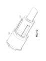
- FIG. 1Ais a perspective view of a blood collection set and collection tube holder.
- FIG. 1Bis a top plan view of the blood collection set and collection tube holder shown in FIG. 1.
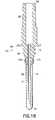
- FIG. 2is side elevation view of the non-patient needle assembly, partly in section.
- FIG. 3is a cross-sectional side view of an embodiment of the female luer in the non-patient needle assembly of the blood collection set.
- FIG. 4is also a cross-sectional side view similar to FIG. 3, but showing an alternate embodiment of the invention
- FIG. 5is a side elevation view of FIG. 4 from the aspect of 7-7
- FIG. 6is also a cross-sectional side view similar to FIG. 3, but showing an alternate embodiment, of the invention.
- FIG. 7is a side elevation view of FIG. 6
- FIG. 8is a cross-sectional side view of the female to male luer interface in this embodiment of the non-patient needle assembly of the blood collection set.
- FIG. 9is a perspective view of an embodiment of a female luer design in the non-patient needle assembly of the blood collection set.
- FIG. 10is a perspective view similar to FIG. 9, but showing an alternate embodiment of the invention
- FIG. 11is a perspective view similar to FIG. 9, but showing an alternate embodiment of the invention.
- FIG. 12is a perspective view similar to FIG. 9, but showing an alternate embodiment of the invention
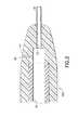
- FIG. 13is a cross-sectional side view of the female to male luer interface in this embodiment of the non-patient needle assembly of the blood collection set.
- FIG. 14is a cross-sectional side view of an embodiment of the male luer non-patient assembly
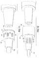
- FIG. 15Ais also a cooss-scctional side view similar to FIG. 14, but showing an alternate embodiment of the invention.
- FIG. 15Bis also a cross-sectional side view similar to FIG. 14, but showing an alternate embodiment ot the invention
- FIG. 15Cis a magnified view of FIG. 15R from the aspect of Detail B.
- FIG. 16Ais also a cross-sectional side view similar to FIG. 14, but showing an alternate embodiment of the invention
- FIG. 16Bis a side elevation view of FIG. 16A from the aspect of X-X
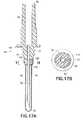
- FIG. 17Ais also a cross-sectional side view similar to FIG. 14, but showing an alternate embodiment of the invention.
- FIG. 17Bis a side elevation view of FIG. 17A from the aspect of Y-Y.
- FIG. 18is also a cross-sectional side view similar to FIG. 14, but showing an alternate embodiment of the invention.
- FIG. 19is also a cross-sectional side view similar to FIG. 14, but showing an alternate embodiment of the invention
- FIG. 20is also a cross-sectional side view similar to FIG. 14, but, showing an alternate embodiment of the invention.
- FIG. 21is a cross-sectional side view of an embodiment of the interface between the non-patient cannula hub the mate luer hub
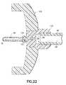
- FIG. 22is a cross-sectional side view of an embodiment of the non-patient needle assembly.
- FIG. 23is a cross-sectional side view of an embodiment of the non-patient needle assembly of the blood collection set.
- FIG. 24is also a cross-sectional side view similar to FIG. 23, but showing an alternate embodiment of the invention.
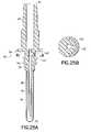
- FIG. 25Ais a cross-sectional side view of an embodiment of the non-patient needle assembly of the blood collection set.
- FIG. 25Bis a side elevation view of FIG. 25A from the aspect of R-R.
- FIG. 26is a perspective view of an embodiment of the female and male luer interface in the non-patient needle assembly of the blood collection set.
- FIG. 27is a perspective view of an embodiment of the non-patient barb multiple sample sleeve interface in the non-patient needle assembly of the blood collection set.
- FIG. 28is a cross-sectional view of an embodiment of the breathable cord design.
- FIG. 29is also a cross-sectional side view similar to FIG. 28, but showing an alternate embodiment of the invention
- FIG. 30is also a cross-sectional side view similar to FIG. 14, but showing an alternate embodiment of the invention.
- FIG. 31is also a cross-sectional side view similar to FIG. 14, but showing an alternate embodiment of the invention
- FIG 32is also a cross-sectional side view similar to FIG. 14, but showing an alternate embodiment of the invention
- FIG. 33is also a cross-scctional side view similar to FIG. 14, but showing an alternate embodiment of the invention
- FIG. 35is also a cross-sectional side view similar to FIG. 14, but showing an alternate embodiment of the invention
- FIG. 36is also a cross-sectional side view similar to FIG. 14, but showing an alternate embodiment of the invention.
- FIG. 37is also a cross-sectional side view similar to FIG. 14, but showing an alternate embodiment of the invention
- FIG. 38is a cross-sectional side view of an embodiment of the non-patient needle assembly of the blood collection set.
- FIG. 39is a cross-sectional side view of the flexible tubing in an embodiment of the blood collection set.
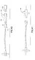
- FIG. 40is a perspective view of one embodiment of the blood collection set
- FIG. 41is a perspective view simi!ar to FIG. 40, but showing an alternate embodiment of the invention
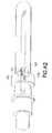
- FIG. 42is a cross-sectional side view of the non-patient needle assembly of the blood collection set.
- the inventionis a self-venting blood collection set with a self-venting mechanism that permits escape of air during use which, typically, also prevents an outflow of fluid, such as blood.
- venting mechanismindicates one or more features or elements that provide venting of air, but which, typically, prevent fluid from passing through.
- vent mediacould be, for example, a distinct physical element such as a plug of insert, a integral portion of a device that has been treated such as by laser drilling or has been formed in whole or in part from a porous material, or a coating, layer, etc. formed by disposing a material onto the device, e.g., by dipping, coating, spraying or the like.
- FIGS. 1A and 1BA prior art blood collection set in accordance with the subject invention is identified generally by the numeral 10 in FIGS. 1A and 1B.
- Blood collection set 10is employed in this embodiment with a collection tube holder 12.
- Holder 12has a proximal end 14, a distal end 16 and a tubular sidewall 18 extending between the ends.
- Proximal end 14 of holder 12is widely open and defines an entry to a tube receptacle within sidewall 18.
- an evacuated collection tubecan be slid in a proximal-to-distal direction through open proximal end 14 of holder 12 toward distal end 16.
- Distal end 16 of holder 12is characterized by an end wall 20.
- End wall 20is formed with an internally threaded mounting aperture 22, as shown in FIG. 2
- Blood collection set 10includes an IV needle assembly 24 that comprises an IV hub 26 .
- IV hub 26includes a proximal end 28, a distal end 30 and a passage (not shown) extending between the ends IV needle assembly 24 further includes an IV cannula 32 with a proximal end 34 , a pointed distal end 36 and a lumen 38 extending between the ends.
- Proximal end 34 of IV cannula 32is mounted securely in the passage of IV hub 26 .
- lumen 38 through IV cannula 32communicates with the passage through IV hub 26 .
- Flexible wings 40are mounted to IV hub 26 at a location near distal end 30 .
- Wings 40can be folded into face-to-face relationship with one another for convenient gripping between a thumb and forefinger to enable manipulation of IV needle assembly 24 Wings 40, however, also can be rotated into a substantially coplanar disposition for taping to the skin of a patient.
- IV needle assembly 24further includes a tubular shield 42 that is telescoped over IV hub 26 .
- Shield 42is formed with transverse slots 44 that slidably receive wings 40.
- shield 42can be slid from a proximal position, as shown in FIGS. 1A and 1B to a distal position IV cannula 32 is exposed for use when shield 42 is in the proximal position shown in FIGS. 1A and 1B.
- IV cannula 32is substantially surrounded by shield 42 when shield 42 is moved to the distal position.
- slots 44 in shield 42are configured to lockingly engage wings 40 when shield 42 is in the distal position to prevent or complicate a re-exposure of IV cannula 32 .
- the shieldillustratcd in FIGS.
- 1A and 1Bis one of many optional shield designs that can be incorporated into blood collection set 10 .
- Other designsmay provide wings mounted directly to the shield.
- Still other designsmay provide a hinged shield mounted to IV hub 26 .
- a shieldmay be entirely separate from IV needle assembly 24 or a shield may not be provided at all Moreover, an unshielded set is also possible according to the invention.
- Blood collection set 10further includes a length of flexible plastic tubing 46.
- Tubing 46includes opposite proximal and distal ends 48 and 50 and a passage extending between the ends.
- Distal end 50 of tubing 46is securely mounted to proximal end 28 of IV hub 26 so that the passage through IV hub 26 communicates with the passage through tubing 46 .
- a female luer fitting 52is securely mounted to proximal end 48 of tubing 46.
- Non-patient needle assembly 54includes a non-patient hub 56 with a proximal end 58, a distal end 60 and a fluid passage 62 extending between the ends exterior surface regions of non-patient hub 56 substantially adjacent proximal end 58 define an array or external threads 64 configured for threaded engagement with the internal threads formed in mounting aperture 22 of collection tube holder 12 .
- External surface regions of non-patient hub 56 adjacent distal enddefine a male luer taper 66 configured for mating with female luer fitting 52.
- Non-patient needle assembly 54further includes a non-patient cannula 68 having a pointed proximal end 70 , a distal end 72 and a lumen 74 extending between the ends. Distal end 72 of non-patient cannula 68 is mounted securely in passage 62 through non-patient hub 56 and aligns substantially with external threads 64 on non-patient hub 56.
- Non-patient needle assembly 54further includes a multiple sample sleeve 76 mounted over non-patient cannula 68 and securely engaged with proximal end 58 of non-patient hub 56. Multiple sample sleeve 76 effectively functions as a valve that prevents a flow of fluid from non-patient cannula 68. However, multiple sample sleeve 76 can be pierced by pointed proximal end 70 of non-patient cannula 68 in response to forces generated by a stopper on an evacuated collection tube.
- Blood collection set 10is employed by folding wings 40 into face-to-face engagement with one another and gripping wings 40 between a thumb and forefinger. Any packaging cover that may be mounted over IV cannula 32 then is removed and discarded. Pointed distal end 36 of IV cannula 32 then is urged into a targeted blood vessel. The healtheare practitioner then may release the grip on wings 40 , and if long term access to the blood vessel is required, wings 40 may be taped into face-to-face engagement with the skin of the patient. Blood collection set 10 includes a plurality of internal spaces that will initially be at ambient air pressure.
- These internal spacesinclude lumen 38 through IV cannula 32, the passage through IV hub 26, the passage through flexible tubing 46, passage 62 through non-patient hub 56 and lumen 74 through non-patient cannula 68.
- the venous or arterial access achieved with IV cannula 32places these interior spaces of blood collection set 10 in communication with the pressure of the blood in the patient. Blood pressure exceeds the ambient air pressure. Accordingly, the pressure of air in the above-referenced internal spaces will increase, and blood will begin to flow into these internal spaces As discussed above, prior art systems may reach equilibrium as the air pressure within the blood collection set increases in response to a reduction of volume caused by the inflow of blood.
- a portion of the internal spaces in the prior art systemmay remain filled with air at a pressure substantially equal to the venous or arterial pressure.
- a prior art systemwill include its original volume of air in the space between the proximal end of the non-patient needle and the blood that enters the blood collection set. This high-pressure air will escape into the first evacuated collection tube that is placed in communication with the non-patient needle.
- the first collection tube employed with prior art systemsnormally is a discard tube.
- FIGS. 3-42show various embodiments of the invention, including various configurations of venting mechanisms in blood collection tubing sets.
- FIGS. 3 to 12reflect embodiments in which a venting mechanism is located in the female luer 52 portion.
- FIG. 13reflects embodiments where the venting mechanism is located between the interface of the female luer 111 and the male luer taper 66.
- FIGS. 14-20reflect embodiments where the venting mechanism is located beyond the proximal end 70 of the non-patient cannula in the non-patient hub 56
- FIG. 21reflects an embodiment where the venting mechanism is remote from the blood collection flow path and that communicates with it through a tortuous path in the non-patient hub.
- FIG. 3 to 12reflect embodiments in which a venting mechanism is located in the female luer 52 portion.
- FIG. 13reflects embodiments where the venting mechanism is located between the interface of the female luer 111 and the male luer taper 66.
- FIGS. 14-20reflect embodiments where
- FIG. 22reflects an embodiment where the venting mechanism is a unified non-patient hub 132.
- FIGS. 23 and 24reflect embodiments where the venting mechanism is a hole in the non-patient cannula.
- FIG. 25reflects an embodiment where the venting mechanism is located between male luer wall 125 and the threads 64 of the non-patient hub.
- FIGS. 26 to 37reflect embodiments where the venting mechanism is a breathable cord.
- FIGS. 38 and 39reflect embodiments where the venting mechanism is a one-way valve.
- FIGS 40 and 41reflect embodiments where the venting mechanism is a "Y" or "T" branching in the fluid passage into which the air is displaced
- FIG. 42reflects an embodiment of a combination of two venting mechanisms located in the non-patient hub
- FIG. 3shows a venting mechanism that includes an aperture 82 extending radially from the interior of the of the luer 52a to the exterior.
- a venting plug 101is located within at least a portion of the aperture 82.
- Aperture 82thereby provides communication between the fluid passage 62 and the ambient surroundings allowing air to escape but preventing the outflow of blood or other fluids.
- Venting plug 101(and like elements described herein) may be formed from any suitable material
- FIG. 4shows a luer 52e, having an axially extending aperture 82c and a venting plug 101 located therein, the aperture running substantially, parallel to the fluid passage 62.
- the apertureprovides communication between passage 62 of non-patient hub 56 and the ambient surroundings.
- FIG. 5shows a side view of Fig 4 from the aspect of Z-Z.
- the venting mechanismcomprises two axially extending apertures 82e and 82f each containing a venting plug 101.
- the luer 52ccontains two projections 83e and 83f in which the apertures are located.
- one or more aperturesmay be located outside the projection. These projections also serve to facilitate the removal of the female luer 52e off the mating male luer 66 .
- Each projectiondoes not necessarily have a vent aperture
- FIGs 8 and 9show another female luer venting mechanism in which a venting ring 102 is situated around the proximal end 99 of the flexible tube 48.
- the venting ringforms an interference fit with the inside female luer taper 103.
- a fluid chamber 104is formed between the interface of the venting ring/ proximal end of the tubing and the non-patient hub distal end 60 when the male luer taper is mated to the female luer, such that air can escape by passing through the venting ring and out of venting apertures 105 to the ambient surroundings.
- the aperturesmay be located anywhere in the body of the female luer. In FIGs 8 and 9, the apertures are located in the distal end of the female luer 106.
- An alternative embodimentcan be send in FIG. 10 in which the venting apertures are longitudinal venting windows 107 which abut the distal side of the venting ring 102 .
- FIG. 11shows a venting mechanism in which a series of transverse vent apertures 108, each containing a venting plug 101 are located in the body of the luer 52.
- the aperturesare spaced equally around the circumference of the proximal end of the female luer fitting 109.
- FIG. 12shows a series of transverse vent apertures 108, each containing a venting plug 101 , that are equally spaced mound the circumference of the distal end of the female luer fitting 52.
- a fluid chamberexists between the male luer taper and the female luer taper surfaces where air can flow out of the fluid passage and out of the vent mechanism.
- FIG. 13shows a venting mechanism that includes a venting plug 101 at a location between the interface of the female luer 111 and the male luer taper 66, which provides communication between passage 62 of non-patient hub 56 and the ambient surroundings.
- the venting plug 101acts as a spacer and forms an interference fit with the inside female luer taper 103.
- a fluid chamber 104is formed between the interface of the female luer taper/proximal end of the tubing 99 and the non-patient hub distal end 60 when the male luer taper is mated to female luer with the venting plug located in-between, such that air can escape by passing through the gap 110 between the male luer and female luer tapered surfaces and the venting plug 101.
- the vent materialcould be a variety of materials or elements.
- configurations for this embodimentmay include, for example, a porous ring formed from a hydrophobic material or which has a hydrophobic surface, a porous ring that becomes seated upon contact with blood using biological phenomena, a ring of swellable material, a textured surface, or a coating of a swellable or similar material
- Several embodimentsinvolve a venting mechanism location beyond the proximal end 70 of the non-patient cannula.
- airflows from the fluid passage 62 and out of the non-patient cannula proximal end 70 where it further flows through the space 112 between needle exterior 68 and multiple sample sleeve 76 interior to the location of the vent 113, which consists of a passage through the non-patient barb 114 then through the venting plug 115 that permits an outflow of air, but prevents an outflow of blood or other fluids to the ambient surroundings.
- FIGs 15A, 15B, 15C, 16A, 16B, 17A, 17B, 18, 19A and 19Bdemonstrate more embodiments where venting mechanisms arc located beyond the proximal end 70 of the non-patient cannula.
- the embodiments in FIGs 15A, 15B and 15Cshow a venting plug 116 that also functions as the non-patient barb.
- FIGs 16A and 16Bshow an embodiment in which a slit 117 in the non-patient barb 114 allows air to escape to a venting disc 118.
- FIGs 17A and 17Bshow an alternative embodiment in which a slit 119 in the non-patient barb 114 contains a venting plug 120
- FIG. 18shows a modified non-patient barb design 122 in which a venting sleeve 121 allows air to escape.
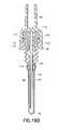
- FIG. 19Ashows a further embodiment in which air escapes through a small channel 123 in the non-patient barb 114 into a thread reservoir 124 then through a channel in the male luer wall 125 into a cylindrical venting plug 126 FIG.
- 19Bshows another embodiment in which the non-patient hub is made from 2 separate parts; the male luer 174 and the non-patient thread assembly 175. Air escapes through a small channel 172 inbetween the needle exterior 68 and the non-patient barb 114 and then through the male luer wall 56 into a reservoir 170 in the male luer that contains the vent media 171 and out to the surrounding atmosphere through a channel 173 at the interface between the male luer 174 and the non-patient thread assembly 175 of the non-patient hub
- the vent media(and like elements described herein) permits an outflow of air, but prevents an outflow of blood or other fluids to the ambient surroundings
- FIG. 20shows another embodiment, of the venting mechanism location beyond the proximal end 70 of the non-patient cannula.
- airis vented through the material of the multiple sample sleeve 127 itself, which functions as the vent media that prevents a flow of fluid from non-patient cannula 68.
- Multiple sample sleeve 127maintains its normal function of being pierced by pointed proximal end 70 of non-patient cannula 68 in response to forces generated by a stopper on an evacuated collection tube. It is possible to make a multiple sample sleeve 127 that also functions as a vent by forming the sleeve from a porous hydrophobic material, such as those disclosed above
- FIG. 21shows a venting mechanism that is remote from the blood collection flow path and that communicates with it through a tortuous path, thereby preventing contamination of blood in the fluid passage by contact with the vent media.
- Airflows from the fluid passage 62 within the male luer 128 into a tortuous air pathway 129 that is formed by the male luer 128 and the non-patient cannula hub 130. Air then passes from the tortuous air pathway 129 to the vent media, which is an annular venting ring 131 and into the ambient surroundings.
- FIG. 22shows a venting mechanism that is a unified non-patient hub 132, at least a portion of which is made from a porous material. This porous portion of the hub 132 itself thus acts as the vent media
- the proximal end 99 of the flexible tubing 48is bonded to the distal end of the unified non-patient hub 133.
- the non-patient cannula 68is bonded to the proximal end of the unified non-patient hub 134 .
- the holderwill typically be pro-attached by bonding, rather than by providing threads on the hub 132 . However threads can be provided if desired.
- Bonding of the tube holder 135 to the unified non-patient hub 134may be accomplished by solvent, welding, heat, pressure or and other convenient means or combination thereof. Air flows through the fluid passage 62 and vents to the ambient surroundings by passing through the unified non-patient hub 132.
- An alternative embodimentincorporates an impermeable spot coat to the inside surface wall 136 of the unified non-patient hub 132 that is part of the fluid passage 62. This results in air only being able to vent through the hub at the non-patient barb 137 beyond the proximal end 70 of the non-patient cannula.
- the venting mechanismis an opening in the non-patient cannula, surrounded by the vent media, which is shown as a vent plug.
- FIG. 23shows a hole 138 in the non-patient cannula 68. Air flows from the fluid passage 62 and out through the hole 138 into a porous venting ring 139 then into the ambient surroundings.
- the hole 140 in the non-patient cannula 68is situated at the non-patient barb 141, which also acts as a venting ring. This allows air to escape through the hole 140 that was in the fluid passage between the IV needle assembly and through the non-patient barb 141 for air in a further proximal location down the fluid passage stream after said hole 140
- FIGs 25A and 25Bshow a venting mechanism that is located between male luer wall 125 and the threads 64 of the non-patient hub. Air flows from the fluid passage 62 into the vent hole 142 and then through the porous C clamp vent plug 143 to the ambient surroundings.
- the vent plug material in this embodimenttypically has an elastic property and shape such that spring energy holds the vent material onto the device. In this embodiment the distortion of the C-shaped vent plug shape is required for the vent plug to stretch over the receiving structure on the hub. Once the vent plug is placed over the receiving structure, it is released and fully maintained in place using its own resiliency and in absence of bonding materials such as epoxies, which could be disadvantageously absorbed into the vent plug.
- the vent mechanism of this embodimentcould alternatively involve first compressing the vent material, placing the vent material into the opening, and releasing the vent material to expand into the opening.
- FIG. 26 and 27show the venting mechanism of a breathable venting cord at two different locations along the fluid passage, though venting using this mechanism may be accomplished by locating the vent media (e.g., placing, coating, or treating) between any one or multiple scaling surfaces along the fluid passage.
- FIG. 26shows the cord 144 located between the scaling surfaces of the female 145 and male 146 luer tapers. The presence of the cord in the scaling surface allows air to escape from the fluid passage 62 but prevents leakage of a fluid through either the absorbent nature of the cord material and / or the very small size of the channel created by the cord FIG.
- FIGS 28 to 37show cross-sections of suitable breathable cords. Other shapes, or combinations or such profiles, may also be used. Cords may be extruded or woven, for example and the application of a hydrophobic coating such as wax may be advantageous.
- the venting mechanismutilizes a one way valve located somewhere along the fluid passage.
- the valveallows air to escape but shuts closed when vacuum is applied thus, when an evacuated collection tube is applied at the needle tip, the tube draws blood from the fluid passage but not air.
- Figs. 38 and 39show examples of a one-way valve.
- the venting mechanismmay be at any location or locations along the fluid passage 62, but is typically at the proximal end of the non-patient hub 56.
- the valve 148itself may be a thin flap such as plastic film 149 covering the vent, a deformable seal such as a rubber or plastic duckbill valve, a deformable wrap over the vent, or any other means or combination of these.
- the valve 148may be proximal or distal with respect to the vent.
- the thin plastic film valve 149is attached to the non-patient hub 56 along one sealed edge of the film 151, so that on the initial venous puncture, air is pushed out of the fluid passage 62 under venous pressure through the porous vent plug 150 and out from underneath the unsecured edges of the plastic film 149.
- a vacuumis applied to the fluid passage 62 (via the attachment of a blood collection tube)
- the thin plastic film valve 149is pulled tight against the porous vent plug 150 thereby sealing the vent and preventing air from reentering the fluid passage.
- This embodimentmay thus provide a primary or back-up feature to prevent air from re-entering the system after venting occurs.
- FIG. 39An alternate embodiment is shown in FIG. 39, in which the blood flows from a length of conventional flexible tubing 48 into a venting mechanism that consists of a length of porous tubing 152, which is loosely wrapped around its outer surface in a length of a non-porous flexible film 153.
- This wrap 153is sufficiently loose to allow air to escape on initial venous puncture such that under a vacuum, it is pulled tight and seals the outer surface of the length of porous tubing 152.
- FIGS. 40 and 41show a venting mechanism using a "Y" or “T” branching in the fluid passage into which the air is displaced.
- the branchingmay be at any location or locations along the fluid passage, but is typically at the proximal end such as at the non-patient hub.
- FIG. 40shows a "Y" Branch Vent 154 in the form of a separate component added into the fluid passage 62 such as in between the female 155 and male luer 156 fittings.
- FIG. 41shows a "I" Branch Vent 157 , which is an integral part of the non-patient hub, thus reducing the number of components.
- the vent plug 158allows the air to escape but prevents leakage of blood.
- Y or "I” Branch Ventmay be accomplished with any convenient terminal shapes at the interfaces of each component.
- the embodiments exemplified previouslyare shown with luer tapered fittings but other interface designs such as direct connection to the flexible tubing may also be applied.
- typical applicationsuse a three port "Y” or “I” branch vent the use of a multiple port branch vent system is also possible.
- vent mechanismsin a single device, or put identical vent mechanisms at more than one location in a device Moreover it is possible to use any of a variety of vent plugs in the vent mechanisms of the invention In addition, vent mechanisms herein may be applicable in a variety of devices other than blood collection sets.
- FIG. 42shows a combination of two venting mechanisms Air flows from the fluid passage 62 and out through the hole 159 in the non-patient cannula 68 into a porous venting ring 160 then into the ambient surroundings.
- a second vent pathexists past beyond the proximal end 70 of the non-patient cannula. Air that is proximal to the hole 159 location flows from the fluid passage 62 and out of the non-patient cannula proximal end 70 where it further flows through the space 112 between needle exterior 68 and multiple sample sleeve 76 interior to the slit 161 in the non-patient barb 162 also allows air to escape to the porous venting ring 160.
- Vent mediacan include, for example, either or a combination of:
- a porous plugis formed from a hydrophobic material, such as high-density polyethylene (IIDPE), which is coated with, impregnated with, of otherwise contains a hydrophilic material such as carboxymethylcellulose (CMC) or a polyacrylate.
- hydrophobic materialsinclude but are not limited to polytetrafluoroethylene (PTFE), ultra-high molecular weight polyethylene (IJIIMWPII), Nylon 6, polypropylene (PP), polyvinylidine fluoride (PVDF) or polyethersulfone (PES).
- An embodiment of the vent mediaconsists of micro-sized holes formed in an exterior wall.
- the holesare large enough to permit airflow but small enough to prevent blood leakage.
- the vent holesmay be any number including a single hole although multiple holes arc typical for a more reliable function.
- the holesmay be laser-drilled, meaning that they may be burned through the wall or substrate using one or more laser beams.
- the substratemay be any convenient material although thin plastic or plastic film is typical.
- the vent mechanismmay include a one-way valve as previously described.
- the vent mechanismmay be located at any convenient space along the fluid passage in the flexible tubing, luer or non-patient hub or in an added component although location at the proximal end is typical to provide flash along the full length of the tubing
- a porous plug that becomes sealed upon contact with blood using biological phenomenamay use, for example, a porous material such as a sintered plastic, ceramic or metal, or a breathable cord, or by locating the biological agent in small holes or spaces between parts.
- the ventmay be of any convenient shape.
- the ventingmay be at any location or locations along the fluid passage, but is preferably at the proximal end such as at the hub near the collection device.
- the ventis typically made from contains, is adjacent to, or works in collaboration with, a stimulant that interacts with blood to promote clotting and/or cell agglutination such that the clot and/or clumped cells block ongoing flow of blood through the vent.
- An example a clotting stimulantis silica or crushed glass, or fiberglass.
- an agglutinizing agentis lectin.
- An example of a platelet activatoris collagen or thrombin.
- a neutralizer for anti-coagulantsuch as protomine sulfate may be included the biological stimulant may be applied using any convenient process including as a powder, a solution, a suspension, a slurry, or any other form. It may be dried or lyophilized.
Landscapes
- Health & Medical Sciences (AREA)
- Life Sciences & Earth Sciences (AREA)
- Engineering & Computer Science (AREA)
- Biomedical Technology (AREA)
- Medical Informatics (AREA)
- Biophysics (AREA)
- Pathology (AREA)
- Hematology (AREA)
- Veterinary Medicine (AREA)
- Heart & Thoracic Surgery (AREA)
- Physics & Mathematics (AREA)
- Molecular Biology (AREA)
- Surgery (AREA)
- Animal Behavior & Ethology (AREA)
- General Health & Medical Sciences (AREA)
- Public Health (AREA)
- Manufacturing & Machinery (AREA)
- Vascular Medicine (AREA)
- Measurement Of The Respiration, Hearing Ability, Form, And Blood Characteristics Of Living Organisms (AREA)
Abstract
Description
- a porous plug formed from a matrix or carrier material, typically hydrophobic, that is coatedwith, impregnated with, or otherwise contains a hydrophilic material that swells on contact with aqueous or water containing substances. This swellable nature thereby provides the scalingfunction in the vent upon contact with blood;
- an air vent provided through a matte finish, micro-sized channels, laser drilled holes, tortuouspath, or a vent provided between sealing surfaces, e.g., in a cord in which the holes, gaps orchannels arc large enough to permit airflow but small enough to prevent, blood leakage;
- a porous plug that becomes sealed upon contact with blood using biological phenomena, eg., byclotting and/or cell agglutination that blocks the vent;
- a superabsorbant material to seal the vent by swelling on contact, with a aqueous fluid; or
- a one-way valve, e.g., a thin flap such as plastic film covering a vent, a deformable seal such asa rubber or plastic duckbill valve, or a deformable wrap over a vent.
Claims (62)
- A blood collection set comprising;a first needle assembly having a first hub and a first cannula mounted to said firsthub, said first cannula having a lumen extending therethrough,a length of flexible tubing having opposite first and second ends and a passageextending between said ends, said fust end of said flexible tubing being in communicationwith said first hub for providing communication between said lumen of said first cannulaand said passage through said flexible tubing,a second hub having a passage extending therethrough and being in fluidcommunication with said second end of said flexible tubing,a non-patient cannula having opposite proximal and distal ends and a lumenextending between said ends, said distal end of said non-patient cannula being mounted tosaid second hub such that said lumen through said non-patient, cannula communicates withsaid passage through said second hub,a multiple sample sleeve covering said non-patient cannula and mounted tosaid second hub.a venting mechanism providing communication between said passage and ambientsurroundings, wherein said venting mechanism permits an outflow of air from said bloodcollection set to said ambient surroundings through said venting mechanism, and whereinsaid venting mechanism substantially prevents an outflow of fluid from said blood collectionset to said ambient surroundings through said venting mechanism.
- The blood collection set of Claim 1, further comprising a female luer fitting mountedto said second end of said flexible tubing, such that said venting mechanism extends through saidfemale luer.
- The blood collection set of Claim 2, wherein said venting mechanism comprises avent media
- The blood collection set of Claim 2, wherein said venting mechanism comprises atleast one aperture through said female luer, said aperture containing a venting plug
- The blood collection set of Claim 2, wherein said venting mechanism comprises aventing ring surrounding said second end of said flexible tubing and at least one aperture throughsaid female luer located distally of said venting ring.
- The blood collection set of Claim 1, further comprising a female luer fitting mountedto said second end of said flexible tubing and a male luer taper formed on said second hub, whereinsaid female luer fitting is mated with said male luer taper, and wherein said venting mechanism islocated between said female luer and said male luer taper.
- The blood collection set of Claim 6, wherein said venting mechanism comprises aventing plug.
- The blood collection set of Claim 6, wherein said venting mechanism comprises aporous ring of hydrophobic material or said venting mechanism comprises a ring of porous materialwith a hydrophobic surface.
- The blood collection set of Claim 6, wherein said venting mechanism comprises abreathable venting cord
- The blood collection set of Claim 6, wherein said venting mechanism comprises atextured surface.
- The blood collection set of Claim 1, wherein said venting mechanism extendsthrough said second hub.
- The blood collection set of Claim 11, wherein said venting mechanism comprises avent media.
- The blood collection set of Claim 11, wherein said venting mechanism comprises apassage through said second hub, said passage containing a venting plug
- The blood collection set of Claim 13, wherein said venting mechanism furthercomprises a one-way valve
- The blood collection set of Claim 1, wherein said venting mechanism is located insaid passage beyond said proximal end of said non-patient cannula.
- The blood collection set of Claim 15, wherein said venting mechanism comprises avent media
- The blood collection set of Claim 1, wherein said second hub further comprises anon-patient barb to which said multiple sample sleeve is mounted, and wherein said ventingmechanism extends through said non-patient barb.
- The blood collection set of Claim 17, wherein said venting mechanism comprises avent media.
- The blood collection set of Claim 17, wherein said venting mechanism comprises apassage though said non patient bath, said passage containing a venting plug.
- The blood collection set of Claim 17, wherein said venting mechanism comprises aslit through said non patient barb and a venting disc
- The blood collection set of Claim 17, wherein said venting mechanism comprises atleast one aperture through said non patient barb, said aperture containing a venting plug.
- The blood collection set of Claim 1, wherein said second hub further comprises anon-patient barb, and wherein said non-patient barb comprises said venting mechanism.
- The blood collection set of Claim 22, wherein said venting mechanism comprises avent media.
- The blood collection set of Claim 22, wherein at least a portion of said non-patientbarb is formed from a porous hydrophobic material or said portion of said non-patient barbcomprises a porous material with a hydrophobic surface.
- The blood collection set of Claim 22, wherein said venting mechanism comprises aporous material impregnated with a hydrophilic material.
- The blood collection set of Claim 1, wherein said second hub further comprises anon-patient barb to which said multiple sample sleeve is mounted, and wherein said ventingmechanism is located between said non-patient barb and said multiple sample sleeve.
- The blood collection set of Claim 26, wherein said venting mechanism comprises aventing sleeve.
- The blood collection set of Claim 27, wherein said venting sleeve comprises aporous hydrophobic material of said venting sleeve comprises a porous material with a hydrophobicsurface.
- The blood collection set of Claim 26, wherein said venting mechanism comprises abreathable venting cord.
- The blood collection set of Claim 26, wherein said venting mechanism comprises atextured surface.
- The blood collection set of Claim 1, wherein said multiple sample sleeve comprisessaid venting mechanism.
- The blood collection set of Claim 31, wherein at least a portion of said multiplesample sleeve is formed from a porous hydrophobic material or said portion of said multiple samplesleeve comprises a porous material with a hydrophobic surface.
- The blood collection set of Claim 1, wherein said venting mechanism comprises atortuous path providing said communication between said passage and said ambient surroundings.
- The blood collection set of Claim 33, wherein said second hub further comprises amale luer and a non-patient cannula hub, and wherein said tortuous path is located between saidmale luer and said non-patient cannula hub.
- The blood collection set of Claim 1, wherein at least a portion of said second hub isformed from a vent media such that said second hub constitutes said venting mechanism.
- The blood collection set of Claim 1, wherein at least a portion of said second hub isformed from a porous material such that said second hub constitutes said venting mechanism
- The blood collection set of Claim 36, further comprising a layer of impermeable spotcoat on the inside surfaces of said second hub
- The blood collection set of Claim 1, wherein said second hub further comprises amale luer and a non-patient thread assembly, which form a reservoir when mated together.
- the blood collection set of Claim 38, wherein said venting mechanism comprises afirst channel through said non patient thread assembly to said reservoir, a second channel from saidreservoir to said ambient surroundings, and a venting plug located in said reservoir.
- The blood collection set of Claim 1, wherein said venting mechanism extendsthrough said non patient cannula.
- The blood collection set of Claim 40, wherein said venting mechanism comprises avent media.
- The blood collection set of Claim 40, wherein said venting mechanism comprises ahole through said non patient cannula and a porous venting ring.
- The blood collection set of Claim 40, wherein said venting mechanism comprises ahole through said non patient cannula and a resilient porous vent plug, wherein said resilience ofsaid vent plug secures said vent plug in location around said hole
- The blood collection set of Claim 1, wherein said venting mechanism extendsthrough said flexible tubing.
- The blood collection set of Claim 44, wherein said venting mechanism comprises avent media.
- The blood collection set of Claim 44, wherein said venting mechanism comprises alength of porous tubing and a one-way valve wrapped around said length of porous tubing.
- The blood colleclion set of Claim 1, further comprising a branch vent incommunication with said passage.
- The blood collection set of Claim I, wherein said second hub further comprises a Ybranch vent or a T branch vent in communication with said passage.
- The blood collection set of Claim 1, wherein said venting mechanism comprises avent media.
- The blood collection set of Claim 1, wherein said venting mechanism comprises aporous hydrophobic material or said venting mechanism comprises a porous material with ahydrophobic surface.
- The blood collection set of Claim 50, wherein said hydrophobic material is selectedfrom the group consisting of glass fiber, high-density polyethylene (HDPE), polytetrafluoroethylene(PTFE), ultra-high molecular weight polyethylene (UHMWPE), Nylon 6, polypropylene (PP),polyvinylidine fluoride (PVDF) and polyethersulfone (PES)
- The blood collection set of Claim 1, wherein said venting mechanism comprises ahydrophilic material.
- The blood collection set of Claim 52, wherein said hydrophilic material iscarboxymethylcellulose or a polyactylate.
- The blood collection set of Claim 1, wherein said venting mechanism comprises;
a porous plug; and
a material that swells on contact with aqueous substances - The blood collection set of Claim 1, wherein said venting mechanism comprises anair vent, wherein said air vent comprises at least one element selected from the group consisting of amatte finish, micro-sized channels, laser drilled holes, and a tortuous path.
- The blood collection set of Claim 1, wherein said venting mechanism comprises abreathable venting cord.
- The blood collection set of Claim 1, wherein said venting mechanism comprises aone way valve.
- The blood collection set of Claim 1, wherein said venting mechanism comprises aporous plug and a biologically active agent.
- The blood collection set of Claim 1, wherein said venting mechanism comprises asuperabsorbant material.
- The blood collection set of Claim 1, further comprising a shield for selectivelycovering said first cannula.
- The blood collection set of Claim 1, further comprising a second venting mechanism
- The blood collection set of Claim 1, further comprising at least one wing attached tosaid first needle assembly.
Applications Claiming Priority (2)
| Application Number | Priority Date | Filing Date | Title |
|---|---|---|---|
| US57614004P | 2004-06-02 | 2004-06-02 | |
| US576140P | 2004-06-02 |
Publications (1)
| Publication Number | Publication Date |
|---|---|
| EP1602329A1true EP1602329A1 (en) | 2005-12-07 |
Family
ID=34940051
Family Applications (1)
| Application Number | Title | Priority Date | Filing Date |
|---|---|---|---|
| EP05104729AWithdrawnEP1602329A1 (en) | 2004-06-02 | 2005-06-01 | Blood Collection Set With Venting Mechanism |
Country Status (5)
| Country | Link |
|---|---|
| US (3) | US20050273019A1 (en) |
| EP (1) | EP1602329A1 (en) |
| JP (2) | JP2005349195A (en) |
| CN (1) | CN100539943C (en) |
| BR (1) | BRPI0501962A (en) |
Cited By (20)
| Publication number | Priority date | Publication date | Assignee | Title |
|---|---|---|---|---|
| EP1665986B1 (en)* | 2004-11-29 | 2009-06-03 | Becton, Dickinson and Company | Blood collection set with an expanded internal volume |
| WO2014172232A1 (en)* | 2013-04-15 | 2014-10-23 | Becton, Dickinson And Company | Medical device for collection of a biological sample |
| WO2015039153A1 (en)* | 2013-09-17 | 2015-03-26 | Greiner Bio-One Gmbh | Removal unit for bodily fluids, in particular blood |
| US9380973B2 (en) | 2013-04-15 | 2016-07-05 | Becton, Dickinson And Company | Biological fluid sampling transfer device and biological fluid separation and testing system |
| US9380972B2 (en) | 2013-04-15 | 2016-07-05 | Becton, Dickinson And Company | Biological fluid collection device and biological fluid collection and testing system |
| US9408568B2 (en) | 2013-04-15 | 2016-08-09 | Becton, Dickinson And Company | Biological fluid sampling device |
| US9517026B2 (en) | 2013-04-15 | 2016-12-13 | Becton, Dickinson And Company | Biological fluid collection device and biological fluid separation and testing system |
| US9549700B2 (en) | 2013-04-15 | 2017-01-24 | Becton, Dickinson And Company | Biological fluid sampling transfer device and biological fluid separation and testing system |
| US9597028B2 (en) | 2013-04-15 | 2017-03-21 | Becton, Dickinson And Company | Biological fluid collection device and biological fluid separation and testing system |
| WO2017151052A1 (en)* | 2016-03-04 | 2017-09-08 | Vigmed Ab | Blood collection device |
| US9833182B2 (en) | 2013-04-15 | 2017-12-05 | Becton, Dickinson And Company | Biological fluid separation device and biological fluid separation and testing system |
| US10080516B2 (en) | 2013-04-15 | 2018-09-25 | Becton, Dickinson And Company | Biological fluid collection device and biological fluid separation and testing system |
| US10154808B2 (en) | 2013-04-15 | 2018-12-18 | Becton, Dickinson And Company | Biological fluid separation device and biological fluid separation and testing system |
| US10194851B2 (en) | 2013-04-15 | 2019-02-05 | Becton, Dickinson And Company | Blood sampling transfer device and blood separation and testing system |
| US10342471B2 (en) | 2013-04-15 | 2019-07-09 | Becton, Dickinson And Company | Biological fluid transfer device and biological fluid sampling system |
| US10791975B2 (en) | 2013-04-15 | 2020-10-06 | Becton, Dickinson And Company | Biological fluid transfer device and biological fluid sampling system |
| US10925532B2 (en) | 2015-08-06 | 2021-02-23 | Becton, Dickinson And Company | Biological fluid collection device and biological fluid collection system |
| US10925530B2 (en) | 2013-04-15 | 2021-02-23 | Becton, Dickinson And Company | Blood sampling transfer device |
| WO2022061217A1 (en) | 2020-09-21 | 2022-03-24 | Becton, Dickinson And Company | Blood collection devices, systems, and methods to facilitate air priming |
| WO2022218924A1 (en)* | 2021-04-12 | 2022-10-20 | B. Braun Melsungen Ag | Vent devices and related methods |
Families Citing this family (82)
| Publication number | Priority date | Publication date | Assignee | Title |
|---|---|---|---|---|
| US20050273019A1 (en)* | 2004-06-02 | 2005-12-08 | Becton, Dickinson And Company | Blood collection set with venting mechanism |
| JP4994775B2 (en)* | 2006-10-12 | 2012-08-08 | 日本コヴィディエン株式会社 | Needle point protector |
| US8197420B2 (en) | 2006-12-18 | 2012-06-12 | Magnolia Medical Technologies, Inc. | Systems and methods for parenterally procuring bodily-fluid samples with reduced contamination |
| MX2009006857A (en)* | 2006-12-29 | 2009-07-07 | Tyco Healthcare | Vented phlebotomy needle with flashback chamber. |
| WO2008100500A2 (en)* | 2007-02-12 | 2008-08-21 | Porex Corporation | Porous barrier media comprising color change indicators |
| US10080578B2 (en)* | 2008-12-16 | 2018-09-25 | Nico Corporation | Tissue removal device with adjustable delivery sleeve for neurosurgical and spinal surgery applications |
| US8403822B2 (en)* | 2009-02-20 | 2013-03-26 | Cytyc Corporation | Passive vent for brachytherapy balloon catheters |
| US8383044B2 (en)* | 2009-07-09 | 2013-02-26 | Becton, Dickinson And Company | Blood sampling device |
| WO2011030282A1 (en)* | 2009-09-09 | 2011-03-17 | Poly Medicure Limited | Blood collection device |
| PL2490592T3 (en)* | 2009-10-22 | 2014-11-28 | Medigard Ltd | Blood flash needle |
| USD635254S1 (en)* | 2010-02-22 | 2011-03-29 | Becton, Dickinson And Company | Needle hub |
| USD627880S1 (en)* | 2010-02-22 | 2010-11-23 | Becton, Dickson And Company | Needle hub |
| USD644733S1 (en)* | 2010-02-22 | 2011-09-06 | Becton, Dickinson And Company | Needle hub |
| USD635253S1 (en)* | 2010-02-22 | 2011-03-29 | Becton, Dickinson And Company | Needle hub |
| USD627881S1 (en)* | 2010-02-22 | 2010-11-23 | Becton, Dickinson And Company | Needle hub |
| USD638539S1 (en)* | 2010-02-22 | 2011-05-24 | Becton, Dickinson And Company | Needle hub |
| CN102232834A (en)* | 2010-04-09 | 2011-11-09 | 中国人民解放军第三军医大学第一附属医院 | Disposable automatic blood sampling device |
| US8747333B2 (en) | 2010-07-15 | 2014-06-10 | Becton, Dickinson And Company | Blood test strip and an intravenous catheter system |
| US9028425B2 (en) | 2010-07-15 | 2015-05-12 | Becton, Dickinson And Company | Vented blood sampling device |
| US8597252B2 (en) | 2010-07-15 | 2013-12-03 | Becton, Dickinson And Company | Removable flash chamber |
| US9549701B2 (en)* | 2010-07-19 | 2017-01-24 | Becton, Dickinson And Company | Device and method for collecting a blood sample |
| EP2585145B1 (en) | 2010-08-19 | 2014-03-05 | West Pharmaceutical Services, Inc. | Rigid needle shield |
| ES2662356T3 (en) | 2011-04-27 | 2018-04-06 | Kpr U.S., Llc | Safety IV catheter assemblies |
| EP2721103A1 (en) | 2011-06-15 | 2014-04-23 | Porex Corporation | Sintered porous plastic liquid barrier media and applications thereof |
| US8864684B2 (en) | 2011-10-13 | 2014-10-21 | Magnolia Medical Technologies, Inc. | Fluid diversion mechanism for bodily-fluid sampling |
| US10980462B2 (en)* | 2011-10-26 | 2021-04-20 | Hummingbird Med Devices, Inc. | Micro-volume blood transfer device |
| US8702658B2 (en) | 2011-12-29 | 2014-04-22 | William L. Spearman | IV catheter insertion device and method |
| BR112014019775A8 (en)* | 2012-03-08 | 2021-05-18 | Becton Dickinson Co | |
| US9060724B2 (en) | 2012-05-30 | 2015-06-23 | Magnolia Medical Technologies, Inc. | Fluid diversion mechanism for bodily-fluid sampling |
| US9022950B2 (en) | 2012-05-30 | 2015-05-05 | Magnolia Medical Technologies, Inc. | Fluid diversion mechanism for bodily-fluid sampling |
| US9204864B2 (en) | 2012-08-01 | 2015-12-08 | Magnolia Medical Technologies, Inc. | Fluid diversion mechanism for bodily-fluid sampling |
| WO2014033911A1 (en)* | 2012-08-31 | 2014-03-06 | テルモ株式会社 | Blood sampling device and blood bag system |
| EP2906269B1 (en) | 2012-10-11 | 2018-01-03 | Magnolia Medical Technologies, Inc. | System for delivering a fluid to a patient with reduced contamination |
| CN109171766A (en) | 2012-11-30 | 2019-01-11 | 木兰医药技术股份有限公司 | Body fluid barrier means and the method for completely cutting off body fluid using body fluid barrier means |
| US10772548B2 (en) | 2012-12-04 | 2020-09-15 | Magnolia Medical Technologies, Inc. | Sterile bodily-fluid collection device and methods |
| CA3183294A1 (en) | 2012-12-04 | 2014-06-12 | Magnolia Medical Technologies, Inc. | Sterile bodily-fluid collection device and methods |
| CN108433732B (en) | 2013-03-12 | 2021-05-28 | 木兰医药技术股份有限公司 | Apparatus and method for selectively occluding a lumen of a needle body |
| US9456775B2 (en)* | 2013-09-06 | 2016-10-04 | Millaghi Medical, Inc. | Passive safety I.V. blood collection catheter |
| EP3721854B1 (en) | 2014-03-03 | 2023-04-05 | Magnolia Medical Technologies, Inc. | Apparatus and methods for disinfection of a specimen container |
| US20160073937A1 (en)* | 2014-09-11 | 2016-03-17 | Becton, Dickinson And Company | Blood sampling system for improving draw success and reducing hemolysis |
| US20160220805A1 (en) | 2015-01-30 | 2016-08-04 | Smiths Medical Asd, Inc. | Intravenous catheter assembly design |
| WO2016123620A1 (en)* | 2015-01-30 | 2016-08-04 | Smiths Medical Asd, Inc. | Needle assembly with diagnostic analysis provisions |
| WO2016201406A1 (en) | 2015-06-12 | 2016-12-15 | Bullington Gregory J | Devices and methods for syringe-based fluid transfer for bodily-fluid sampling |
| ES2908909T3 (en) | 2015-06-19 | 2022-05-04 | Becton Dickinson Co | Biological fluid collection device |
| US10010282B2 (en) | 2015-07-24 | 2018-07-03 | Kurin, Inc. | Blood sample optimization system and blood contaminant sequestration device and method |
| EP4249119A3 (en) | 2015-09-03 | 2023-11-29 | Magnolia Medical Technologies, Inc. | System for maintaining sterility of a specimen container |
| US10525237B2 (en) | 2015-10-28 | 2020-01-07 | Becton, Dickinson And Company | Ergonomic IV systems and methods |
| US10549072B2 (en) | 2015-10-28 | 2020-02-04 | Becton, Dickinson And Company | Integrated catheter with independent fluid paths |
| US10245416B2 (en) | 2015-10-28 | 2019-04-02 | Becton, Dickinson And Company | Intravenous catheter device with integrated extension tube |
| US10744305B2 (en) | 2015-10-28 | 2020-08-18 | Becton, Dickinson And Company | Ergonomic IV systems and methods |
| US10357636B2 (en) | 2015-10-28 | 2019-07-23 | Becton, Dickinson And Company | IV access device having an angled paddle grip |
| US10814106B2 (en) | 2015-10-28 | 2020-10-27 | Becton, Dickinson And Company | Soft push tabs for catheter adapter |
| US10639455B2 (en) | 2015-10-28 | 2020-05-05 | Becton, Dickinson And Company | Closed IV access device with paddle grip needle hub and flash chamber |
| US20170156653A1 (en)* | 2015-12-02 | 2017-06-08 | Taneesha Sharee Scott | Blood Collection Apparatus and Method |
| WO2017201369A1 (en) | 2016-05-20 | 2017-11-23 | Smiths Medical Asd, Inc. | Needle assembly with flexible catheter nose for diagnostic sampling of fluid |
| USD844781S1 (en) | 2016-10-05 | 2019-04-02 | Becton, Dickinson And Company | Needle hub |
| USD819802S1 (en) | 2016-10-05 | 2018-06-05 | Becton, Dickinson And Company | Catheter adapter |
| US10238852B2 (en) | 2016-10-05 | 2019-03-26 | Becton, Dickinson And Company | Septum housing |
| USD835262S1 (en) | 2016-10-05 | 2018-12-04 | Becton, Dickinson And Company | Intravenous catheter assembly |
| USD837368S1 (en) | 2016-10-05 | 2019-01-01 | Becton, Dickinson And Company | Catheter adapter grip |
| EP4218574A3 (en) | 2016-11-18 | 2023-09-06 | Magnolia Medical Technologies, Inc. | Systems and methods for sample collection with reduced hemolysis |
| US10827964B2 (en) | 2017-02-10 | 2020-11-10 | Kurin, Inc. | Blood contaminant sequestration device with one-way air valve and air-permeable blood barrier with closure mechanism |
| JP6792789B2 (en)* | 2017-05-26 | 2020-12-02 | 株式会社トップ | adapter |
| JP2020528781A (en) | 2017-07-25 | 2020-10-01 | クリン インコーポレイテッド | Needle assembly with needle safety shield |
| EP4555929A3 (en) | 2017-09-12 | 2025-06-25 | Magnolia Medical Technologies, Inc. | Fluid control device |
| JP7229267B2 (en) | 2017-12-07 | 2023-02-27 | マグノリア メディカル テクノロジーズ,インコーポレイテッド | Fluid control device and method of use |
| JP7447492B2 (en)* | 2018-01-26 | 2024-03-12 | ニプロ株式会社 | hub assembly |
| BR112020022230A2 (en)* | 2018-05-01 | 2021-02-02 | Becton, Dickinson And Company | cover with ventilation plug for biological fluid collection device |
| US11857320B2 (en) | 2018-06-08 | 2024-01-02 | Smiths Medical Asd, Inc. | Blood sequestration device and method |
| JP7413381B2 (en) | 2018-11-20 | 2024-01-15 | スペクトラム・ソリューションズ・エルエルシー | Sample collection system with sealing cap and valve |
| US20200229744A1 (en)* | 2019-01-18 | 2020-07-23 | Americord Registry Llc | Device for the improved collection of cord blood from an umbilical cord |
| WO2020163744A1 (en) | 2019-02-08 | 2020-08-13 | Magnolia Medical Technologies, Inc. | Devices and methods for bodily fluid collection and distribution |
| CN113784793B (en) | 2019-03-11 | 2023-09-19 | 木兰医药技术股份有限公司 | Fluid control device and method of using the same |
| IL286812B1 (en) | 2019-04-01 | 2025-08-01 | Kurin Inc | Device and system for optimizing sampling of non-aerated liquids |
| CA3139687A1 (en)* | 2019-05-09 | 2020-11-12 | Vascular Integrity | Improved all-in one syringe assembly for blood draws and medicine delivery to patients |
| US11701094B2 (en) | 2019-06-20 | 2023-07-18 | Spectrum Solutions L.L.C. | Sample collection system including valve and plug assemblies |
| KR102385826B1 (en)* | 2020-01-15 | 2022-04-13 | 서효석 | connection holder of vacuum assisted blood colection tube needle set |
| KR102542554B1 (en) | 2020-12-01 | 2023-06-12 | 인제대학교 산학협력단 | Medical apparatus for arterial blood collection |
| AU2022206656A1 (en) | 2021-01-05 | 2023-07-20 | Becton, Dickinson And Company | Needle hub for drug delivery device |
| JP2024504631A (en)* | 2021-01-15 | 2024-02-01 | ベクトン・ディキンソン・アンド・カンパニー | Blood collection assembly and related devices and methods |
| US20230191033A1 (en) | 2021-12-17 | 2023-06-22 | Kurin, Inc. | Syringes configured to inhibit forward plunger movement |
| EP4299089A1 (en)* | 2022-06-28 | 2024-01-03 | Ypsomed AG | Needle assembly for an injection or infusion device |
Citations (8)
| Publication number | Priority date | Publication date | Assignee | Title |
|---|---|---|---|---|
| GB1345979A (en)* | 1971-04-30 | 1974-02-06 | Abbott Lab | Blood collecting assemblies |
| US4416290A (en)* | 1982-08-30 | 1983-11-22 | Becton Dickinson And Company | Multiple sample needle assembly with vein indication |
| DE3229783C1 (en)* | 1982-08-10 | 1984-01-05 | B. Braun Melsungen Ag, 3508 Melsungen | Bleeding device |
| US4444203A (en)* | 1982-03-26 | 1984-04-24 | Lab-A-Cath, Inc. | Intravenous catheter placing and specimen gathering device |
| EP0376168A2 (en)* | 1988-12-30 | 1990-07-04 | Spacelabs, Inc. | Blood-sampling device |
| EP0619096A1 (en)* | 1993-02-22 | 1994-10-12 | Issei Suzuki | Needle assembly for a blood sample collection |
| WO1999023947A1 (en)* | 1997-11-12 | 1999-05-20 | Mdc Investment Holdings, Inc. | Fluid collection device with captured rectractable needle |
| EP1442705A1 (en)* | 2003-01-16 | 2004-08-04 | Becton, Dickinson and Company | Blood collection set with venting mechanism |
Family Cites Families (70)
| Publication number | Priority date | Publication date | Assignee | Title |
|---|---|---|---|---|
| US3382865A (en)* | 1965-10-18 | 1968-05-14 | Ashton L. Worrall Jr. | Device for taking multiple blood samples or the like |
| US3585984A (en)* | 1968-04-10 | 1971-06-22 | Parke Davis & Co | Blood transfer device |
| GB1256478A (en)* | 1969-09-12 | 1971-12-08 | ||
| US3817240A (en)* | 1972-06-28 | 1974-06-18 | Becton Dickinson Co | Multiple sample needle assembly with one-way valve and blood flow indicator |
| US3874367A (en)* | 1972-06-29 | 1975-04-01 | Becton Dickinson Co | Valved blood sampling needle assembly |
| US4108175A (en)* | 1977-01-28 | 1978-08-22 | Orton Dale W | Catheter insertion apparatus |
| US4106497A (en)* | 1977-02-04 | 1978-08-15 | Becton, Dickinson And Company | Multiple sample needle assembly with indicator means |
| US4166450A (en)* | 1977-07-22 | 1979-09-04 | Metatech Corporation | Device and procedure for collecting a succession of intravenous blood samples |
| US4154229A (en)* | 1977-08-10 | 1979-05-15 | Becton, Dickinson And Company | Blood collection system with venipuncture indicator |
| US4207870A (en)* | 1978-06-15 | 1980-06-17 | Becton, Dickinson And Company | Blood sampling assembly having porous vent means vein entry indicator |
| US4193400A (en)* | 1978-06-16 | 1980-03-18 | The Deseret Company | Intravenous needle assembly with air bleed plug |
| US4269186A (en)* | 1978-06-16 | 1981-05-26 | The Deseret Company | Intravenous needle assembly with air bleed plug |
| US4317445A (en)* | 1980-03-31 | 1982-03-02 | Baxter Travenol Laboratories, Inc. | Catheter insertion unit with separate flashback indication for the cannula |
| US4340068A (en)* | 1980-06-18 | 1982-07-20 | Becton, Dickinson And Company | Multiple sample needle with vein entry indicator |
| US4312362A (en)* | 1980-10-02 | 1982-01-26 | Becton, Dickinson And Company | Single sample needle with vein entry indicator |
| US4436098A (en)* | 1981-03-16 | 1984-03-13 | Becton Dickinson Company | Needle assembly with vein entry indicator |
| JPS57190567A (en)* | 1981-05-20 | 1982-11-24 | Terumo Corp | Blood sampler with air removing and shielding mechanism |
| US4416291A (en)* | 1981-07-20 | 1983-11-22 | Becton Dickinson And Company | Multiple sample needle assembly with vein entry indicator |
| US4412548A (en)* | 1981-07-30 | 1983-11-01 | Becton Dickinson And Company | Multiple sample needle assembly |
| US4409990A (en)* | 1981-10-13 | 1983-10-18 | Mileikowsky Gil N | Fluid sampling needle assembly and method of use thereof |
| US4398544A (en)* | 1981-10-15 | 1983-08-16 | Becton Dickinson And Company | Single and multiple sample needle assembly with vein entry indicator |
| US4886072A (en)* | 1983-12-16 | 1989-12-12 | Becton, Dickinson And Company | Multiple sample needle assembly with vein indicator |
| US4679571A (en)* | 1984-08-31 | 1987-07-14 | Becton, Dickinson And Company | Blood sample needle assembly with vein indicator |
| US4865592A (en)* | 1986-02-20 | 1989-09-12 | Becton, Dickinson And Company | Container and needle assembly |
| US4650468A (en)* | 1986-02-26 | 1987-03-17 | Jennings Jr Baldwin P | Medical syringe |
| US4844089A (en)* | 1986-05-14 | 1989-07-04 | Lamberto Roberti | Needle for multiple vacuum blood sample devices |
| EP0352322B1 (en)* | 1986-12-11 | 1994-09-21 | Terumo Kabushiki Kaisha | Blood sampling tube |
| US4788986A (en)* | 1987-03-16 | 1988-12-06 | Harris Jim C | Holder for blood collecting needle |
| JPS63315033A (en)* | 1987-06-18 | 1988-12-22 | Terumo Corp | Method and apparatus for collecting blood specimen |
| US4894052A (en)* | 1988-08-22 | 1990-01-16 | Becton, Dickinson And Company | Flash detection in an over the needle catheter with a restricted needle bore |
| JPH02297342A (en)* | 1988-09-28 | 1990-12-07 | Terumo Corp | Blood drawing and/or injection device using both cutter needle-shaped medical needle and holder, and the same medical needle and holder |
| JPH02139656U (en)* | 1989-01-18 | 1990-11-21 | ||
| US4971068A (en)* | 1989-07-07 | 1990-11-20 | Bio-Plexus, Inc. | Blood vessel locating needle assembly with thermochromic indicator |
| US5092845A (en)* | 1989-07-10 | 1992-03-03 | Critikon, Inc. | Catheter with needle gasket |
| DE4000968C1 (en)* | 1990-01-16 | 1991-06-20 | Dieter 2090 Drage De Wendelborn | Blood sampling apparatus - has blood observation chamber mounted in sampling vessel stopper |
| US5122121A (en)* | 1990-08-30 | 1992-06-16 | E-Z-Em, Inc. | Safety needle assembly |
| US5222502A (en)* | 1990-09-26 | 1993-06-29 | Terumo Kabushiki Kaisha | Blood collecting needle |
| US5030207A (en)* | 1990-11-02 | 1991-07-09 | Becton, Dickinson And Company | Instantaneous vein entry indicator for intravenous needle |
| US5032116A (en)* | 1991-01-09 | 1991-07-16 | Becton, Dickinson And Company | Flashback plug |
| US5290246A (en)* | 1991-01-18 | 1994-03-01 | Terumo Kabushiki Kaisha | Piercing needle |
| JPH0613744Y2 (en)* | 1991-01-18 | 1994-04-13 | テルモ株式会社 | Puncture needle |
| US5120319A (en)* | 1991-06-26 | 1992-06-09 | Critikon, Inc. | Flash tube for intravenous catheter |
| US5295969A (en)* | 1992-04-27 | 1994-03-22 | Cathco, Inc. | Vascular access device with air-tight blood containment capability |
| US5290238A (en)* | 1992-06-10 | 1994-03-01 | Imed Corporation | Self priming tubing set for an infusion device |
| US5306259A (en)* | 1992-08-10 | 1994-04-26 | Cathco, Inc. | Vascular access needle having an extended length body |
| US5360408A (en)* | 1992-11-16 | 1994-11-01 | Vaillancourt Vincent L | Shielded hypodermic needle assembly and a shield assembly for a hypodermic needle |
| US5411487A (en)* | 1992-12-07 | 1995-05-02 | Castagna; John F. | Hypodermic syringe with automatic needle cover |
| DE4402690C2 (en)* | 1994-01-29 | 1996-09-12 | Sarstedt Walter Geraete | Blood collection device |
| DE9405166U1 (en)* | 1994-03-26 | 1994-05-26 | Krebs, Peter, Dr., 78048 Villingen-Schwenningen | Spinal cannula with transparent handle |
| US5450856A (en)* | 1994-04-25 | 1995-09-19 | Norris; Wendal A. | Phlebotomy needle attachable to a vacuum container with a vent to preclude blood flashback |
| US5697914A (en)* | 1995-03-16 | 1997-12-16 | Becton Dickinson And Company | Control forward/flashback forward one hand introducer needle and catheter assembly |
| US5542932A (en)* | 1995-07-20 | 1996-08-06 | Daugherty; Charles W. | Bloodless flashback vent |
| DE19617000C1 (en)* | 1996-04-27 | 1998-01-22 | Sarstedt Walter Geraete | Blood collection device with a holder having a cannula |
| US5830190A (en)* | 1996-06-11 | 1998-11-03 | Becton Dickinson And Company | Protected needle catheter placement device having needle placement visualization features and method for its use |
| DE19645514C2 (en)* | 1996-11-05 | 2000-04-13 | Sarstedt Ag & Co | Method and device for disposing of the cannula of a blood collection device |
| US5893844A (en)* | 1997-01-17 | 1999-04-13 | Misawa Medical Industry Co., Ltd. | Indwelling needle set |
| EP0989872A4 (en)* | 1997-06-17 | 2000-08-30 | Injectimed Inc | Method and apparatus for introducing an intravenous catheter |
| AU8619698A (en)* | 1997-07-25 | 1999-02-16 | Ban C. H. Tsui | Devices, systems and methods for determining proper placement of epidural catheters |
| IT1297759B1 (en)* | 1997-11-13 | 1999-12-20 | Cgm Spa | DEVICE FOR THE COLLECTION OF BODY LIQUIDS AND FOR THEIR TRANSFER IN TUBES. |
| US5984895A (en)* | 1998-01-15 | 1999-11-16 | Merit Medical Systems, Inc. | Vascular blood flashback containment device with improved sealing capability |
| FR2782627B1 (en)* | 1998-09-01 | 2001-02-09 | Vygon | ARTERIAL PUNCTURE NEEDLE |
| US6533760B2 (en)* | 2000-05-02 | 2003-03-18 | Becton, Dickinson And Company | Flashback blood collection needle |
| CN1313052C (en)* | 2001-01-12 | 2007-05-02 | 爱科来株式会社 | piercing device |
| US6712792B2 (en)* | 2001-05-02 | 2004-03-30 | Becton, Dickinson And Company | Flashback blood collection needle |
| CN2479917Y (en)* | 2001-06-18 | 2002-03-06 | 施国平 | Hemostix |
| SG121744A1 (en)* | 2002-11-06 | 2006-05-26 | Becton Dickinson Co | Flashback blood collection needle with needle shield |
| US7226432B2 (en)* | 2004-05-03 | 2007-06-05 | Clear View Patient Safety Products, Llc | Blood drawing device |
| US20050273019A1 (en)* | 2004-06-02 | 2005-12-08 | Becton, Dickinson And Company | Blood collection set with venting mechanism |
| EP1602328A1 (en)* | 2004-06-02 | 2005-12-07 | Becton, Dickinson and Company | Flashback Blood Collection Needle |
| JP2006098226A (en)* | 2004-09-29 | 2006-04-13 | Fuji Photo Film Co Ltd | Anomaly detection method for syringe pump, liquid suction/discharge apparatus, and biochemical analyzer |
- 2005
- 2005-05-31USUS11/141,446patent/US20050273019A1/ennot_activeAbandoned
- 2005-06-01BRBR0501962-1Apatent/BRPI0501962A/ennot_activeIP Right Cessation
- 2005-06-01EPEP05104729Apatent/EP1602329A1/ennot_activeWithdrawn
- 2005-06-02CNCNB2005100922151Apatent/CN100539943C/ennot_activeExpired - Lifetime
- 2005-06-02JPJP2005163168Apatent/JP2005349195A/enactivePending
- 2008
- 2008-01-09USUS11/971,679patent/US20080194986A1/ennot_activeAbandoned
- 2009
- 2009-05-22USUS12/470,916patent/US20100094171A1/ennot_activeAbandoned
- 2011
- 2011-10-24JPJP2011233153Apatent/JP2012066090A/ennot_activeWithdrawn
Patent Citations (8)
| Publication number | Priority date | Publication date | Assignee | Title |
|---|---|---|---|---|
| GB1345979A (en)* | 1971-04-30 | 1974-02-06 | Abbott Lab | Blood collecting assemblies |
| US4444203A (en)* | 1982-03-26 | 1984-04-24 | Lab-A-Cath, Inc. | Intravenous catheter placing and specimen gathering device |
| DE3229783C1 (en)* | 1982-08-10 | 1984-01-05 | B. Braun Melsungen Ag, 3508 Melsungen | Bleeding device |
| US4416290A (en)* | 1982-08-30 | 1983-11-22 | Becton Dickinson And Company | Multiple sample needle assembly with vein indication |
| EP0376168A2 (en)* | 1988-12-30 | 1990-07-04 | Spacelabs, Inc. | Blood-sampling device |
| EP0619096A1 (en)* | 1993-02-22 | 1994-10-12 | Issei Suzuki | Needle assembly for a blood sample collection |
| WO1999023947A1 (en)* | 1997-11-12 | 1999-05-20 | Mdc Investment Holdings, Inc. | Fluid collection device with captured rectractable needle |
| EP1442705A1 (en)* | 2003-01-16 | 2004-08-04 | Becton, Dickinson and Company | Blood collection set with venting mechanism |
Cited By (30)
| Publication number | Priority date | Publication date | Assignee | Title |
|---|---|---|---|---|
| EP1665986B1 (en)* | 2004-11-29 | 2009-06-03 | Becton, Dickinson and Company | Blood collection set with an expanded internal volume |
| US10136849B2 (en) | 2013-04-15 | 2018-11-27 | Becton, Dickinson And Company | Biological fluid collection device and biological fluid separation and testing system |
| WO2014172232A1 (en)* | 2013-04-15 | 2014-10-23 | Becton, Dickinson And Company | Medical device for collection of a biological sample |
| US9380973B2 (en) | 2013-04-15 | 2016-07-05 | Becton, Dickinson And Company | Biological fluid sampling transfer device and biological fluid separation and testing system |
| US9380972B2 (en) | 2013-04-15 | 2016-07-05 | Becton, Dickinson And Company | Biological fluid collection device and biological fluid collection and testing system |
| US9408568B2 (en) | 2013-04-15 | 2016-08-09 | Becton, Dickinson And Company | Biological fluid sampling device |
| US9517026B2 (en) | 2013-04-15 | 2016-12-13 | Becton, Dickinson And Company | Biological fluid collection device and biological fluid separation and testing system |
| US9549700B2 (en) | 2013-04-15 | 2017-01-24 | Becton, Dickinson And Company | Biological fluid sampling transfer device and biological fluid separation and testing system |
| US9597028B2 (en) | 2013-04-15 | 2017-03-21 | Becton, Dickinson And Company | Biological fluid collection device and biological fluid separation and testing system |
| US10238325B2 (en) | 2013-04-15 | 2019-03-26 | Becton, Dickinson And Company | Medical device for collection of a biological sample |
| US9808192B2 (en) | 2013-04-15 | 2017-11-07 | Becton, Dickinson And Company | Biological fluid sampling transfer device and biological fluid separation and testing system |
| US9833182B2 (en) | 2013-04-15 | 2017-12-05 | Becton, Dickinson And Company | Biological fluid separation device and biological fluid separation and testing system |
| US10028690B2 (en) | 2013-04-15 | 2018-07-24 | Becton, Dickinson And Company | Biological fluid collection device and biological fluid separation and testing system |
| US10080516B2 (en) | 2013-04-15 | 2018-09-25 | Becton, Dickinson And Company | Biological fluid collection device and biological fluid separation and testing system |
| US11974846B2 (en) | 2013-04-15 | 2024-05-07 | Becton, Dickinson And Company | Biological fluid transfer device and biological fluid sampling system |
| US11291393B2 (en) | 2013-04-15 | 2022-04-05 | Becton, Dickinson And Company | Medical device for collection of a biological sample |
| US10827965B2 (en) | 2013-04-15 | 2020-11-10 | Becton, Dickinson And Company | Biological fluid collection device and biological fluid separation and testing system |
| US10154808B2 (en) | 2013-04-15 | 2018-12-18 | Becton, Dickinson And Company | Biological fluid separation device and biological fluid separation and testing system |
| US10342471B2 (en) | 2013-04-15 | 2019-07-09 | Becton, Dickinson And Company | Biological fluid transfer device and biological fluid sampling system |
| US10791975B2 (en) | 2013-04-15 | 2020-10-06 | Becton, Dickinson And Company | Biological fluid transfer device and biological fluid sampling system |
| US10194851B2 (en) | 2013-04-15 | 2019-02-05 | Becton, Dickinson And Company | Blood sampling transfer device and blood separation and testing system |
| US12082931B2 (en) | 2013-04-15 | 2024-09-10 | Becton, Dickinson And Company | Blood sampling transfer device |
| US10925530B2 (en) | 2013-04-15 | 2021-02-23 | Becton, Dickinson And Company | Blood sampling transfer device |
| WO2015039153A1 (en)* | 2013-09-17 | 2015-03-26 | Greiner Bio-One Gmbh | Removal unit for bodily fluids, in particular blood |
| US10925532B2 (en) | 2015-08-06 | 2021-02-23 | Becton, Dickinson And Company | Biological fluid collection device and biological fluid collection system |
| US11793432B2 (en) | 2015-08-06 | 2023-10-24 | Becton, Dickinson And Company | Biological fluid collection device and biological fluid collection system |
| WO2017151052A1 (en)* | 2016-03-04 | 2017-09-08 | Vigmed Ab | Blood collection device |
| WO2022061217A1 (en) | 2020-09-21 | 2022-03-24 | Becton, Dickinson And Company | Blood collection devices, systems, and methods to facilitate air priming |
| EP4213731A4 (en)* | 2020-09-21 | 2024-11-13 | Becton, Dickinson and Company | BLOOD COLLECTION DEVICES, SYSTEMS AND METHODS FOR FACILITATION OF VENTING |
| WO2022218924A1 (en)* | 2021-04-12 | 2022-10-20 | B. Braun Melsungen Ag | Vent devices and related methods |
Also Published As
| Publication number | Publication date |
|---|---|
| CN100539943C (en) | 2009-09-16 |
| US20050273019A1 (en) | 2005-12-08 |
| US20100094171A1 (en) | 2010-04-15 |
| JP2012066090A (en) | 2012-04-05 |
| US20080194986A1 (en) | 2008-08-14 |
| CN1748643A (en) | 2006-03-22 |
| JP2005349195A (en) | 2005-12-22 |
| BRPI0501962A (en) | 2006-01-24 |
Similar Documents
| Publication | Publication Date | Title |
|---|---|---|
| EP1602329A1 (en) | Blood Collection Set With Venting Mechanism | |
| EP1602328A1 (en) | Flashback Blood Collection Needle | |
| JP7385552B2 (en) | Ported IV catheter with external needle shield and internal blood control septum | |
| AU2003203533B2 (en) | Blood collection set with venting mechanism | |
| JP7041761B2 (en) | Needle assembly | |
| US5295970A (en) | Apparatus and method for vascular guide wire insertion with blood flashback containment features | |
| EP2716218B1 (en) | Flashback Blood Collection Needle | |
| EP0495497B1 (en) | Intravenous catheter | |
| US20100262038A1 (en) | Flashback Blood Collection Needle | |
| AU2011357736A1 (en) | Flashback blood collection needle | |
| GB2065479A (en) | Devices for introducing a catheter or a probe into a blood vessel | |
| EP0973566A1 (en) | Method and apparatus for collecting blood | |
| WO2009113999A2 (en) | Flashback blood collection needle | |
| JP5893149B2 (en) | Blood collection assembly |
Legal Events
| Date | Code | Title | Description |
|---|---|---|---|
| PUAI | Public reference made under article 153(3) epc to a published international application that has entered the european phase | Free format text:ORIGINAL CODE: 0009012 | |
| AK | Designated contracting states | Kind code of ref document:A1 Designated state(s):AT BE BG CH CY CZ DE DK EE ES FI FR GB GR HU IE IS IT LI LT LU MC NL PL PT RO SE SI SK TR | |
| AX | Request for extension of the european patent | Extension state:AL BA HR LV MK YU | |
| RIN1 | Information on inventor provided before grant (corrected) | Inventor name:TOWNS, BRYAN Inventor name:SCHNEIDER, JAMES C. Inventor name:WILKINSON, BRADLEY Inventor name:LEVY, RICHARD Inventor name:BLOCH, CURTIS Inventor name:NEWBY, C. MARK Inventor name:CONWAY, HUGH T. Inventor name:SWENSON, KIRK D. Inventor name:STEWART, MARSDEN Inventor name:BENNETT, MICHAEL Inventor name:ELLIS, ROBERT Inventor name:ISKRA, MICHAEL Inventor name:NAIR, HAREESH | |
| 17P | Request for examination filed | Effective date:20060524 | |
| AKX | Designation fees paid | Designated state(s):AT BE BG CH CY CZ DE DK EE ES FI FR GB GR HU IE IS IT LI LT LU MC NL PL PT RO SE SI SK TR | |
| 17Q | First examination report despatched | Effective date:20110524 | |
| STAA | Information on the status of an ep patent application or granted ep patent | Free format text:STATUS: THE APPLICATION IS DEEMED TO BE WITHDRAWN | |
| 18D | Application deemed to be withdrawn | Effective date:20111206 |