EP1602138B1 - Disposable working electrode for an electrochemical cell - Google Patents
Disposable working electrode for an electrochemical cellDownload PDFInfo
- Publication number
- EP1602138B1 EP1602138B1EP02792413.3AEP02792413AEP1602138B1EP 1602138 B1EP1602138 B1EP 1602138B1EP 02792413 AEP02792413 AEP 02792413AEP 1602138 B1EP1602138 B1EP 1602138B1
- Authority
- EP
- European Patent Office
- Prior art keywords
- working electrode
- electrochemical cell
- cell assembly
- flow
- flow channel
- Prior art date
- Legal status (The legal status is an assumption and is not a legal conclusion. Google has not performed a legal analysis and makes no representation as to the accuracy of the status listed.)
- Revoked
Links
- 239000000758substrateSubstances0.000claimsdescription40
- 239000012530fluidSubstances0.000claimsdescription18
- 239000000463materialSubstances0.000claimsdescription18
- 238000000034methodMethods0.000claimsdescription18
- 229910052719titaniumInorganic materials0.000claimsdescription14
- 239000010936titaniumSubstances0.000claimsdescription14
- RTAQQCXQSZGOHL-UHFFFAOYSA-NTitaniumChemical compound[Ti]RTAQQCXQSZGOHL-UHFFFAOYSA-N0.000claimsdescription13
- 238000000151depositionMethods0.000claimsdescription13
- 229920000620organic polymerPolymers0.000claimsdescription9
- 238000004891communicationMethods0.000claimsdescription8
- 229920000728polyesterPolymers0.000claimsdescription7
- 238000007740vapor depositionMethods0.000claimsdescription7
- 239000007788liquidSubstances0.000claimsdescription6
- 229910052751metalInorganic materials0.000claimsdescription6
- 239000002184metalSubstances0.000claimsdescription6
- 238000004587chromatography analysisMethods0.000claimsdescription5
- 239000011262electrochemically active materialSubstances0.000claimsdescription5
- 239000004697PolyetherimideSubstances0.000claimsdescription4
- 229910045601alloyInorganic materials0.000claimsdescription4
- 239000000956alloySubstances0.000claimsdescription4
- 239000004417polycarbonateSubstances0.000claimsdescription4
- 229920000515polycarbonatePolymers0.000claimsdescription4
- 229920001601polyetherimidePolymers0.000claimsdescription4
- 238000007789sealingMethods0.000claimsdescription4
- VYZAMTAEIAYCRO-UHFFFAOYSA-NChromiumChemical compound[Cr]VYZAMTAEIAYCRO-UHFFFAOYSA-N0.000claimsdescription3
- 239000004642PolyimideSubstances0.000claimsdescription3
- 229910052804chromiumInorganic materials0.000claimsdescription3
- 239000011651chromiumSubstances0.000claimsdescription3
- 229920001721polyimidePolymers0.000claimsdescription3
- 229920000098polyolefinPolymers0.000claimsdescription3
- WFKWXMTUELFFGS-UHFFFAOYSA-NtungstenChemical compound[W]WFKWXMTUELFFGS-UHFFFAOYSA-N0.000claimsdescription3
- 239000010937tungstenSubstances0.000claimsdescription3
- 229910052721tungstenInorganic materials0.000claimsdescription3
- 239000003575carbonaceous materialSubstances0.000claimsdescription2
- 239000004020conductorSubstances0.000claimsdescription2
- 238000004401flow injection analysisMethods0.000claims1
- 210000004027cellAnatomy0.000description42
- 239000000523sampleSubstances0.000description30
- PCHJSUWPFVWCPO-UHFFFAOYSA-NgoldChemical compound[Au]PCHJSUWPFVWCPO-UHFFFAOYSA-N0.000description16
- 239000010931goldSubstances0.000description12
- 229910052737goldInorganic materials0.000description11
- 229910001220stainless steelInorganic materials0.000description9
- 239000010935stainless steelSubstances0.000description9
- 229910021607Silver chlorideInorganic materials0.000description7
- 210000005056cell bodyAnatomy0.000description7
- 230000008021depositionEffects0.000description7
- 239000010408filmSubstances0.000description7
- HKZLPVFGJNLROG-UHFFFAOYSA-Msilver monochlorideChemical compound[Cl-].[Ag+]HKZLPVFGJNLROG-UHFFFAOYSA-M0.000description7
- 239000000243solutionSubstances0.000description7
- 238000004544sputter depositionMethods0.000description6
- 230000008901benefitEffects0.000description5
- 230000008859changeEffects0.000description5
- 238000001514detection methodMethods0.000description5
- 238000004519manufacturing processMethods0.000description5
- 239000010409thin filmSubstances0.000description5
- 229910000831SteelInorganic materials0.000description4
- KZNMRPQBBZBTSW-UHFFFAOYSA-N[Au]=OChemical compound[Au]=OKZNMRPQBBZBTSW-UHFFFAOYSA-N0.000description4
- 239000007772electrode materialSubstances0.000description4
- 239000003480eluentSubstances0.000description4
- 239000011521glassSubstances0.000description4
- 229910001922gold oxideInorganic materials0.000description4
- 238000003754machiningMethods0.000description4
- 230000003647oxidationEffects0.000description4
- 238000007254oxidation reactionMethods0.000description4
- 238000005498polishingMethods0.000description4
- 239000010959steelSubstances0.000description4
- HNSDLXPSAYFUHK-UHFFFAOYSA-N1,4-bis(2-ethylhexyl) sulfosuccinateChemical compoundCCCCC(CC)COC(=O)CC(S(O)(=O)=O)C(=O)OCC(CC)CCCCHNSDLXPSAYFUHK-UHFFFAOYSA-N0.000description3
- VEXZGXHMUGYJMC-UHFFFAOYSA-MChloride anionChemical compound[Cl-]VEXZGXHMUGYJMC-UHFFFAOYSA-M0.000description3
- 230000006835compressionEffects0.000description3
- 238000007906compressionMethods0.000description3
- 239000012528membraneSubstances0.000description3
- 238000005240physical vapour depositionMethods0.000description3
- -1polyethylenePolymers0.000description3
- 239000012488sample solutionSubstances0.000description3
- XKRFYHLGVUSROY-UHFFFAOYSA-NArgonChemical compound[Ar]XKRFYHLGVUSROY-UHFFFAOYSA-N0.000description2
- OKTJSMMVPCPJKN-UHFFFAOYSA-NCarbonChemical compound[C]OKTJSMMVPCPJKN-UHFFFAOYSA-N0.000description2
- KDLHZDBZIXYQEI-UHFFFAOYSA-NPalladiumChemical compound[Pd]KDLHZDBZIXYQEI-UHFFFAOYSA-N0.000description2
- 239000004698PolyethyleneSubstances0.000description2
- 229920006362Teflon®Polymers0.000description2
- 239000000853adhesiveSubstances0.000description2
- 230000001070adhesive effectEffects0.000description2
- 238000005229chemical vapour depositionMethods0.000description2
- 239000011248coating agentSubstances0.000description2
- 238000000576coating methodMethods0.000description2
- 230000001419dependent effectEffects0.000description2
- 238000013023gasketingMethods0.000description2
- 150000002500ionsChemical class0.000description2
- 230000000873masking effectEffects0.000description2
- 239000000203mixtureSubstances0.000description2
- 239000004033plasticSubstances0.000description2
- 229920003023plasticPolymers0.000description2
- BASFCYQUMIYNBI-UHFFFAOYSA-NplatinumChemical compound[Pt]BASFCYQUMIYNBI-UHFFFAOYSA-N0.000description2
- 229920003207poly(ethylene-2,6-naphthalate)Polymers0.000description2
- 229920000573polyethylenePolymers0.000description2
- 239000011112polyethylene naphthalateSubstances0.000description2
- 238000003825pressingMethods0.000description2
- 229910052709silverInorganic materials0.000description2
- 239000004332silverSubstances0.000description2
- NDVLTYZPCACLMA-UHFFFAOYSA-Nsilver oxideChemical compound[O-2].[Ag+].[Ag+]NDVLTYZPCACLMA-UHFFFAOYSA-N0.000description2
- 238000011144upstream manufacturingMethods0.000description2
- XLYOFNOQVPJJNP-UHFFFAOYSA-NwaterSubstancesOXLYOFNOQVPJJNP-UHFFFAOYSA-N0.000description2
- RYGMFSIKBFXOCR-UHFFFAOYSA-NCopperChemical compound[Cu]RYGMFSIKBFXOCR-UHFFFAOYSA-N0.000description1
- LFQSCWFLJHTTHZ-UHFFFAOYSA-NEthanolChemical compoundCCOLFQSCWFLJHTTHZ-UHFFFAOYSA-N0.000description1
- 229920002449FKMPolymers0.000description1
- 229920004459Kel-F® PCTFEPolymers0.000description1
- ZOKXTWBITQBERF-UHFFFAOYSA-NMolybdenumChemical compound[Mo]ZOKXTWBITQBERF-UHFFFAOYSA-N0.000description1
- 239000004677NylonSubstances0.000description1
- BQCADISMDOOEFD-UHFFFAOYSA-NSilverChemical compound[Ag]BQCADISMDOOEFD-UHFFFAOYSA-N0.000description1
- 239000004809TeflonSubstances0.000description1
- 229910001069Ti alloyInorganic materials0.000description1
- 229910052782aluminiumInorganic materials0.000description1
- XAGFODPZIPBFFR-UHFFFAOYSA-NaluminiumChemical compound[Al]XAGFODPZIPBFFR-UHFFFAOYSA-N0.000description1
- 150000001412aminesChemical class0.000description1
- 150000001413amino acidsChemical class0.000description1
- 125000005365aminothiol groupChemical class0.000description1
- 239000012491analyteSubstances0.000description1
- 229910052786argonInorganic materials0.000description1
- 239000012298atmosphereSubstances0.000description1
- QVGXLLKOCUKJST-UHFFFAOYSA-Natomic oxygenChemical compound[O]QVGXLLKOCUKJST-UHFFFAOYSA-N0.000description1
- 230000015572biosynthetic processEffects0.000description1
- 238000007664blowingMethods0.000description1
- 229940075397calomelDrugs0.000description1
- 229910052799carbonInorganic materials0.000description1
- 230000003197catalytic effectEffects0.000description1
- 239000003795chemical substances by applicationSubstances0.000description1
- UUAGAQFQZIEFAH-UHFFFAOYSA-NchlorotrifluoroethyleneChemical compoundFC(F)=C(F)ClUUAGAQFQZIEFAH-UHFFFAOYSA-N0.000description1
- 229920001940conductive polymerPolymers0.000description1
- 239000010949copperSubstances0.000description1
- 229910052802copperInorganic materials0.000description1
- 238000005520cutting processMethods0.000description1
- ZOMNIUBKTOKEHS-UHFFFAOYSA-Ldimercury dichlorideChemical compoundCl[Hg][Hg]ClZOMNIUBKTOKEHS-UHFFFAOYSA-L0.000description1
- 238000003487electrochemical reactionMethods0.000description1
- 238000002474experimental methodMethods0.000description1
- 229920002313fluoropolymerPolymers0.000description1
- 239000004811fluoropolymerSubstances0.000description1
- 239000007789gasSubstances0.000description1
- 229910021397glassy carbonInorganic materials0.000description1
- 150000002337glycosaminesChemical class0.000description1
- 229910002804graphiteInorganic materials0.000description1
- 239000010439graphiteSubstances0.000description1
- 238000010438heat treatmentMethods0.000description1
- 238000004128high performance liquid chromatographyMethods0.000description1
- 230000006872improvementEffects0.000description1
- 238000000338in vitroMethods0.000description1
- 238000001727in vivoMethods0.000description1
- 238000003780insertionMethods0.000description1
- 230000037431insertionEffects0.000description1
- 239000011810insulating materialSubstances0.000description1
- 238000004255ion exchange chromatographyMethods0.000description1
- 238000005259measurementMethods0.000description1
- 230000007246mechanismEffects0.000description1
- 238000001465metallisationMethods0.000description1
- 150000002739metalsChemical class0.000description1
- 238000005459micromachiningMethods0.000description1
- 229910052750molybdenumInorganic materials0.000description1
- 239000011733molybdenumSubstances0.000description1
- 238000012544monitoring processMethods0.000description1
- 229910000510noble metalInorganic materials0.000description1
- 229920001778nylonPolymers0.000description1
- 239000001301oxygenSubstances0.000description1
- 229910052760oxygenInorganic materials0.000description1
- 238000011107packed bed chromatographyMethods0.000description1
- 229910052763palladiumInorganic materials0.000description1
- 239000002245particleSubstances0.000description1
- 238000009832plasma treatmentMethods0.000description1
- 229910052697platinumInorganic materials0.000description1
- 229920000642polymerPolymers0.000description1
- 239000002861polymer materialSubstances0.000description1
- 229920001343polytetrafluoroethylenePolymers0.000description1
- 239000004810polytetrafluoroethyleneSubstances0.000description1
- 125000002924primary amino groupChemical group[H]N([H])*0.000description1
- 230000008569processEffects0.000description1
- 238000001650pulsed electrochemical detectionMethods0.000description1
- 238000004080punchingMethods0.000description1
- 239000010453quartzSubstances0.000description1
- 230000009467reductionEffects0.000description1
- 239000012925reference materialSubstances0.000description1
- 239000012088reference solutionSubstances0.000description1
- 230000000717retained effectEffects0.000description1
- 238000000926separation methodMethods0.000description1
- 239000010703siliconSubstances0.000description1
- 229910052710siliconInorganic materials0.000description1
- VYPSYNLAJGMNEJ-UHFFFAOYSA-Nsilicon dioxideInorganic materialsO=[Si]=OVYPSYNLAJGMNEJ-UHFFFAOYSA-N0.000description1
- 229910001923silver oxideInorganic materials0.000description1
- 239000000126substanceSubstances0.000description1
- 235000000346sugarNutrition0.000description1
- 150000008163sugarsChemical class0.000description1
- 238000006557surface reactionMethods0.000description1
- KKEYFWRCBNTPAC-UHFFFAOYSA-Lterephthalate(2-)Chemical compound[O-]C(=O)C1=CC=C(C([O-])=O)C=C1KKEYFWRCBNTPAC-UHFFFAOYSA-L0.000description1
- 238000012360testing methodMethods0.000description1
- MAKDTFFYCIMFQP-UHFFFAOYSA-Ntitanium tungstenChemical compound[Ti].[W]MAKDTFFYCIMFQP-UHFFFAOYSA-N0.000description1
- 238000004832voltammetryMethods0.000description1
- 238000001039wet etchingMethods0.000description1
Images


Classifications
- G—PHYSICS
- G01—MEASURING; TESTING
- G01N—INVESTIGATING OR ANALYSING MATERIALS BY DETERMINING THEIR CHEMICAL OR PHYSICAL PROPERTIES
- G01N27/00—Investigating or analysing materials by the use of electric, electrochemical, or magnetic means
- G01N27/26—Investigating or analysing materials by the use of electric, electrochemical, or magnetic means by investigating electrochemical variables; by using electrolysis or electrophoresis
- G01N27/28—Electrolytic cell components
- G01N27/30—Electrodes, e.g. test electrodes; Half-cells
- G01N27/307—Disposable laminated or multilayered electrodes
- H—ELECTRICITY
- H01—ELECTRIC ELEMENTS
- H01M—PROCESSES OR MEANS, e.g. BATTERIES, FOR THE DIRECT CONVERSION OF CHEMICAL ENERGY INTO ELECTRICAL ENERGY
- H01M4/00—Electrodes
- H01M4/86—Inert electrodes with catalytic activity, e.g. for fuel cells
- H—ELECTRICITY
- H01—ELECTRIC ELEMENTS
- H01M—PROCESSES OR MEANS, e.g. BATTERIES, FOR THE DIRECT CONVERSION OF CHEMICAL ENERGY INTO ELECTRICAL ENERGY
- H01M4/00—Electrodes
- H01M4/86—Inert electrodes with catalytic activity, e.g. for fuel cells
- H01M4/88—Processes of manufacture
- H01M4/8825—Methods for deposition of the catalytic active composition
- H01M4/8867—Vapour deposition
- H—ELECTRICITY
- H01—ELECTRIC ELEMENTS
- H01M—PROCESSES OR MEANS, e.g. BATTERIES, FOR THE DIRECT CONVERSION OF CHEMICAL ENERGY INTO ELECTRICAL ENERGY
- H01M4/00—Electrodes
- H01M4/86—Inert electrodes with catalytic activity, e.g. for fuel cells
- H01M4/90—Selection of catalytic material
- H01M4/9041—Metals or alloys
- H01M4/905—Metals or alloys specially used in fuel cell operating at high temperature, e.g. SOFC
- H01M4/9058—Metals or alloys specially used in fuel cell operating at high temperature, e.g. SOFC of noble metals or noble-metal based alloys
- Y—GENERAL TAGGING OF NEW TECHNOLOGICAL DEVELOPMENTS; GENERAL TAGGING OF CROSS-SECTIONAL TECHNOLOGIES SPANNING OVER SEVERAL SECTIONS OF THE IPC; TECHNICAL SUBJECTS COVERED BY FORMER USPC CROSS-REFERENCE ART COLLECTIONS [XRACs] AND DIGESTS
- Y02—TECHNOLOGIES OR APPLICATIONS FOR MITIGATION OR ADAPTATION AGAINST CLIMATE CHANGE
- Y02E—REDUCTION OF GREENHOUSE GAS [GHG] EMISSIONS, RELATED TO ENERGY GENERATION, TRANSMISSION OR DISTRIBUTION
- Y02E60/00—Enabling technologies; Technologies with a potential or indirect contribution to GHG emissions mitigation
- Y02E60/30—Hydrogen technology
- Y02E60/50—Fuel cells
- Y—GENERAL TAGGING OF NEW TECHNOLOGICAL DEVELOPMENTS; GENERAL TAGGING OF CROSS-SECTIONAL TECHNOLOGIES SPANNING OVER SEVERAL SECTIONS OF THE IPC; TECHNICAL SUBJECTS COVERED BY FORMER USPC CROSS-REFERENCE ART COLLECTIONS [XRACs] AND DIGESTS
- Y10—TECHNICAL SUBJECTS COVERED BY FORMER USPC
- Y10T—TECHNICAL SUBJECTS COVERED BY FORMER US CLASSIFICATION
- Y10T29/00—Metal working
- Y10T29/49—Method of mechanical manufacture
- Y10T29/49002—Electrical device making
Definitions
- Flow-through electrochemical cellsare used as detectors for a variety of separation systems including chromatographic and ion chromatographic systems.
- Dionex Corporationsells such electrochemical cells under the trademarks ED40 and ED50 cells.
- Such cellsinclude an amperometric working electrode in the form of a cylindrical wire embedded into a plastic block with the tip of the wire exposed to a sample flow-through channel, typically enclosed by a plastic gasket held in place under compression.
- These working electrodesare somewhat complicated and expensive to manufacture. After a period of use, the electrode must be replaced or reconditioned by laborious polishing or other methods which can lead to a lack of reproducibility of the detector output.
- Thin film disposable electrodeshave been used as in vitro test electrodes and as in vivo implantable monitoring electrodes in a variety of applications. See, for example, Michel, et al. U.S. 5,694,932 ; Dahl, et al. U.S. 5,554,178 ; Saban, et al. U.S. 6,110,354 ; Krause, et al. U.S. 4,710,403 ; Grill, Jr., et al. U.S. 5,324,322 ; Kurnik, et al. U.S. 5,989,409 ; Diebold, et al. U.S. 5,437,999 ; Kuennecke, et al.
- a typical salt bridgeis a cylindrical container filled with a 3 M KCl solution.
- the conductive connection to the reference half cell on one side and to the sample on the other sideis realized using ion permeable diaphragms.
- a flow-through electrochemical cell assembly for a chromatography systemis provided with a disposable working electrode structure.
- the assemblyincludes (a) a perimeter wall defining a sample flow channel including an inlet and an outlet, (b) a sample inlet line in fluid communication with the sample flow channel inlet, (c) a sample outlet line providing fluid communication between the sample flow channel outlet and a remote reference electrode, and (d) a disposable working electrode structure comprising an electrically conductive and electrochemically active working electrode region bound as a layer, directly or indirectly, to an electrically insulating substrate surface.
- the substrate surfaceis in fluid-sealing relationship with the sample flow channel, and the working electrode region is in fluid communication with said sample flow channel.
- the working electrode structureis readily removable from said electrochemical cell assembly.
- a methodfor making a disposable electrode structure and sample flow channel for such an assembly.
- the methodcomprises the steps of (a) vapor depositing electrically conductive and electrochemically active material, directly or indirectly, onto an organic polymer substrate through a mask to form a pattern of a working electrode region, and (b) forming a fluid seal between said working electrode region and a perimeter wall to define a fluid sample flow channel with said working electrode region in direct fluid contact with said fluid sample flow channel.
- a flow-through electrochemical cell detectorincluding one embodiment of a disposable working electrode according the present invention.
- Most of the components of this cellcan be similar to a conventional electrochemical cell such as the ED40 cell of Dionex Corporation, with the exception that the disposable working electrode structure replaces a generally permanent electrode structure which is periodically reconditioned as by polishing.
- the flow-through electrochemical cellincludes a sample flow channel in contact with a working electrode.
- Sample analyte in a liquid eluent solutionflows through the sample flow channel and from there through a reference electrode chamber.
- Electrode surface reactionsare carried out on the working electrode, typically including an electrically conductive and electrochemically active material which is in direct contact with the sample solution flowing through the sample flow channel.
- a conventional reference electrode block 12defines a contained cylindrical reference electrode chamber 14 through which the sample solution flows passing through the sample flow channel.
- Another suitable conventional electrodeis in the form of a counter or auxiliary electrode 16.
- auxiliary electrodeThe basic function of the auxiliary electrode is to prevent the electrical current from running through the reference electrode. This is achieved by means of so-called three-electrode potentiostats. See pages 47-48, 239-241, William R. LaCourse, Pulsed Electrochemical Detection in High-Performance Liquid Chromatography, John Wiley, New York 1997, pages 47-48 and 239-241 .
- oxidation or reduction of the reference materialcan take place (e.g. AgCl reduced back to silver or Ag oxidized to silver oxide) or change of chloride concentration in the junction solution which may result in a poor constancy of the reference potential.
- the three-electrode potentiostatswere introduced in the 1950s. Prior to that only two-electrode cells were in general use for voltammetry (i.e. measurement of current while controlling the potential)
- the sample flow channel in contact with the working electrodeis defined by a gasket 18 which is retained in sealing relationship between the lower wall of counter electrode 16 and the upwardly facing wall of disposable working electrode structure 20 to be described hereinafter.
- Gasket 18defines an interior cut-out forming a perimeter wall around sample flow channel 18a.
- the configuration of the sample flow channel 18ais defined by the thickness of gasket 18, and the length and width of the cut-out, preferably in the form of an elongated flow-through slot.
- the working electrode structure 20includes a support substrate 20a, preferably formed of an organic polymer, and includes an electrically conductive and electrochemically active working electrode region 20b, preferable in the form of a thin layer, in a circular shape as illustrated.
- the working electrode region 20bis preferably formed by vapor deposition of an electrically conductive and electrochemically active material, directly or indirectly, onto substrate 20a.
- electrochemically activemeans material suitable for facilitating the required electrochemical reactions for detection in electrochemical cells.
- working electrode structure 20also includes an electrically conductive contact region 20c, suitably also in the form of a circular disk, and an electrically conductive lead 20d interconnecting working electrode region 20b and contact region 20c.
- working electrode region 20b, contact region 20c and lead 20dare formed by vapor deposition of the same electrically conductive material directly or indirectly onto substrate 20a through a mask.
- an adhesion layerpreferrably is first deposited onto an organic substrate to facilitate binding of the electrode material.
- the adhesion materialis of the same configuration as regions 20b and 20c and lead 20d and is also formed by vapor deposition through a mask of substantially the same shape.
- the assemblyincludes a working electrode connection 22, suitably spring loaded and in electrical communication at one end of a potentiostat, including a voltage or current source, and at the other end in electrical contact with region 20c to establish an electrical connection with working electrode region 20b through lead 20d.
- a working electrode connection 22suitably spring loaded and in electrical communication at one end of a potentiostat, including a voltage or current source, and at the other end in electrical contact with region 20c to establish an electrical connection with working electrode region 20b through lead 20d.
- the working electrode region 20bis disposed in the sample flow channel 18a in direct contact with sample flowing therethrough.
- connection pin 22 and contact region 20care disposed to the exterior of sample flow channel 18a out of fluid contact with liquid flowing through the flow channel.
- the working electrode, connector and contact padare located in a planar arrangement on the same side of the polymeric substrate. This makes it possible to manufacture the entire working electrode in what is essentially a two-step deposition (e.g. with Ti and Au).
- the manufacturing of permanent electrodesrequires many more steps: machining of a kel-F block, machining of a steel support plate, covering of a gold wire by a suitable insulating materials, machining of a Teflon ferrule for the liquid seal between the gold wire and the Kel F material, machining of the gold contact pad cylinder, insertion of the gold wire and of the contact pad into the opening in the Kel F material. Curing of the conductive polymer between the electrode wire and the contact pad cylinder. Sanding down the gold wire to the level of the KelF material. Machine lapping of the gold wire, hand-polishing of the gold wire. Of these multiple steps, the hand polishing is very person-dependent and notorious for its lack of reproducibility.
- gasket 18can be formed integral with or adhered to substrate 20 as by an adhesive bond therebetween forming an integral unit which can be readily removed from the cell and replaced by another integral unit.
- gasket 18can be mounted to counter electrode 16 or other support structure. In each of these or other possible configurations, a disposable electrode structure can be removed from the assembly and replaced alone or in combination with a gasket and support plate or holder block.
- Gasket 18typically is flexible with a thickness in the range of about 0.01 to 0.0005 inch consists of a fluoro polymer such as Teflon® or such polymeric materials as polyetherimide or nylon.
- a similar type of gasketcan be used as is used in the ED40 electrochemical cell.
- a gasketsuitably includes an elongate slot for flow channel 18a, suitably 0.5 to 10.0 mm, preferably 0.8 to 5 mm long.
- the channel widthis suitably 0.1 to 3 mm, preferably 0.5 to 1.5 mm.
- the gasketsare suitably 0.005 to 0.5 mm, preferably 0.013 to 0.1 mm thick.
- the gasketcan be held in place by bolts passing through openings in the gasket material at both ends of the gasket.
- the gasketcan also be made an integral part of the disposable electrode.
- the polymeric gasketcan be permanently attached to the disposable electrode. This can be done either by oxygen plasma treatment of both surfaces followed by pressing the gasket against the electrode at room temperature.
- a permanent bonding of gaskets and electrodescan be achieved by using polyethylene coated polyester material of suitable thickness as a gasket. After cutting the material to the proper gasketing shape, the gasket is pressed to the face of the disposable electrode at a suitable elevated temperature, usually about 140°C.
- the sample containing separated analytes in an eluent solutionflows through conventional fittings, not shown, from a chromatographic separator, such as a packed bed chromatography column upstream of the electrochemical cell to flow channel 18a.
- the sample solutionflows through inlet tubing connected to a sample flow channel inlet, not shown, in the path illustrated by arrows 28.
- the inletcan be formed by a pin hole opening through counter electrode 16 in the upstream end of flow channel 18a.
- the solutionflows across flow channel 18a and exits through a sample flow channel outlet in the path illustrated schematically by arrows 30 and flows through a pin hole size opening, not shown, in counter electrode 16 into chamber 14 and exits chamber 14 through a fitting, not shown, through chamber outlet 32.
- a conventional chemical or electrochemical suppressoris disposed between the electrochemical cell detector and the chromatography separator of an ion chromatography system.
- the working electrode regionis disposed within flow channel 18a to contact the flowing sample in eluent solution therein.
- a preferred way to accomplish this and to provide electrical contact with connector pin 22is to space contact region 20c from working electrode region 20b and to interconnect them by lead 20d. This can be accomplished by the use of a mask which includes these three elements vapor deposited through the mask. In this configuration, the three elements are preferably in the form of thin film bound directly or indirectly to substrate 20a.
- a top view of a mask 40 designed for vapor depositing multiple electrode regionis illustrated.
- Maskincludes alignment holes 41 to hold the screen in place and fixing screw 42 together with a fixing bar 44.
- the mask 40is prepared by wet etching of aluminum or stainless steel sheets.
- the electrical patternis defined by openings in the mask.
- One way to vapor deposit the electrode regionis by placing a sheet of polymeric substrate between mask 40 and a stainless steel plate, not shown.
- the maskincludes working electrode opening 40b which defines working electrode region 20b, larger contact region 40c which defines contact region 20c and slot opening 40d which defines lead 20d.
- Suitable mask materialsinclude metal (e.g. stainless steel, molybdenum), glass, quartz and silicon.
- the metallic patternmay be prepared by conventional micro fabrication techniques used in semi-conduction manufacture as described, for example, in M. Madou, Fundamentals of Microfabrication, CRC Press, New York, 1997 . These methods include but are not limited to physical vapor deposition (PVD) and chemical vapor deposition (CVD).
- PVDphysical vapor deposition
- CVDchemical vapor deposition
- an adhesion layeris deposited using the mask 40.
- This methodis illustrated schematically in FIGS. 3a-c .
- a thin film of the adhesion layer 50illustrated as the darkened region 50 in FIG. 3b , is sputtered through opening 40b, 40c, 40d and mask 40 as by sputtering using a high vacuum with Ar plasma.
- Such a techniqueis illustrated in M. Madou, Chapter 2, p. 60, Figure 2.8 of Fundamentals of Microfabrication (CRC, 1997 ).
- FIG. 3cthe mask is maintained in place.
- a suitable electrode material for direct contact with the sample in flow channel 18bis vapor deposited as a second thin film 52 onto a surface of the adhesion layer 50.
- the advantage of the adhesion layeris that it improves the cohesion between the electrode layer and the underlying substrate for any substrate, preferably an organic polymer material.
- the adhesion layeris formed of a material such as titanium, tungsten, chromium and alloys of these materials.
- a titanium or tungsten titanium alloy adhesion layeris particularly effective to improve an adhesion of a metallic working electrode layer to the polymeric substrate.
- a typical thickness for the adhesion layer 50is about 50 ⁇ to 5,000 ⁇ .
- a suitable electrode material in region 20ais a metal, preferably a noble metal such as gold, platinum, copper or silver, or alloys thereof, although gold is the most frequently used one.
- a non-metallic electrodemay be used for region 20b such as a carboneous material (e.g. glassy carbon, graphite or carbon paste) in combination with an adhesion layer such as titanium. Similar sputtering techniques would be employed.
- a typical thickness for the electrode material of layer 52is about 100 ⁇ to 10,000 ⁇ .
- a suitable top view configuration of working electrode region 20bis circular with a diameter of about 0.1 to 3 mm, and suitably about 0.5 to 2.0 mm, preferably about 1 mm.
- a suitable contact region 20cis larger because of the need to accommodate different types of useful contacting arrangements and to ensure good contact with pin 22.
- Substrate 28is preferably of a polymeric material with a thickness in the range of about 5.08 x 10 -2 m to 50.8 x 10 -2 m (0.002 to 0.02 inches). It is preferably flexible for forming a good seal with gasket 18.
- the polymeric materialcan be a polyester (such as polyethylene, terephthalate or polyethylene naphthalate), polycarbonate, polyolefin, polyimide or polyetherimide.
- the polymeric materialis a polyester (PEN or PET-type) or a polycarbonate.
- Other alternative structures for the disposable working electrodesinclude different geometrical shapes of the working electrode area such as triangle, square or rectangle.
- Several possible arrangements relative to the flow pathare possible for each of the non-circular geometries of the working electrodes.
- Also possibleare comb-like patterns of two or more "finger" shaped electrodes connected to the same lead as the circular electrodes but protruding into the flow path either in a parallel or in radial fashion.
- the electronics connecting the systemcan be the ones conventionally used in a Dionex ED40 or 50 electrochemical cell.
- a true reference electrodee.g., Ag/AgCl wire immersed in a reference solution enclosed by suitable diaphragm or a glass membrane may be employed.
- microfabricated electrodesare used in conjunction with a salt bridge-equipped true reference electrode.
- the combination pH/Ag/AgCl electroderepresents an improvement even over a "true" reference electrode.
- An integral part of the detection mechanismis a cyclical creation of a catalytic gold oxide layer on the working electrode's surface.
- the IP AD modefreshly creates and removes the amino acid-detection-enabling gold oxide layer with a frequency of 1 Hz or higher.
- the creation of gold oxideis pH dependent and in consequence different levels of oxidation current are generated as a detection background at different pH.
- any change of eluent pHresults in a strongly sloping chromatographic baseline.
- the glass-membrane equipped true-reference electrodesuch as pH/Ag/AgCl the reference potential changes with pH in an identical fashion as the rate of gold oxide formation.
- the pH-connected change of the reference potentialis thus providing an automatic compensation of the change of the oxidation current.
- the resulting baseline during a pH gradientis then completely flat.
- microfabricated electrodesare used with a pH compensated reference potential (i.e. true reference electrode, salt bridge, glass membrane).
- a pH compensated reference potentiali.e. true reference electrode, salt bridge, glass membrane.
- the electrochemical cell of the present inventioncan be used in any application in which ED40 or ED50 cell is used. Thus, it can be used to detect separated amino acids, sugars, amino sugars, amines, amino thiols or the like.
- One of the advantages of the working electrode and reference electrode of the present inventionis that they are capable of off-setting the change of pH and thus to eliminate excessive base line shifts. This is because of the built-in pH-related compensation of oxidation currents.
- An important advantage of the disposable electrodeis that it can be readily replaced after a single day or multiple day use at low expense before loss of performance of the cell.
- the disposable electrodes of the present inventionare compatible with a commercial low dead volume electrochemical cell. This enables use of a true reference or pH based reference potential.
- Polymeric film substrates obtained from Du Pont or GEwere cleaned of all particles on their surface by blowing off with air, rinsed successively with water, alcohol and then dried in air. After punching the holes required for mounting the masks on top of the film, the polymeric substrates were put on top of a stainless steel base plate. We then placed first a thinner stainless steel mask and then a thicker stainless steel mask on the exposed side of the polymeric film. The patterns of the thinner mask is shown in Figure 2 . The thinner mask defines the shape of the electrode, connection lead and contact pad. The thicker mask, not shown, is used for keeping the thinner mask flat, completely co-planar and in close contact with the polymeric film.
- the thicker maskhas open cutout areas, thus providing the structural integrity without interference with the plasma during the sputtering of titanium and gold.
- the polymeric filmsare sandwiched tightly between the two masks and the supporting base plate. The whole assembly is being held together by bars and screws. The bars are positioned on top of the two masks.
- the polymeric substrates assembled with masksare placed in the sputtering chamber.
- a suitable vacuumis applied for 12 hours (overnight) to reach the vacuum required for sputtering (at least 40 mTorr).
- the water adsorbed inside the polymeris slowly removed from the chamber during that time.
- the substrateremains enclosed in a low-pressure gas atmosphere (ca. 10 mTorr of argon).
- a low-pressure gas atmosphereca. 10 mTorr of argon
- the substrateis connected as anode and the metal source for deposition (target) is connected as cathode.
- a suitable RF frequencyis within the range of 12-14 mHz.
- the suitable range of RF poweris in the range of 1 to 2 kW.
- the deposition rateis different for different metals.
- titanium depositionis ca. 4.7 times slower than the deposition of gold (see for example Table 3.8, page 100, M. Madou, Fundamentals of Micromachining).
- the RF field generated between the substrate and targetis the sole heating source during the metal deposition.
- the temperature of the polymeric substratenever exceeds the range of 50-70°C.
- a titanium layeris sputtered first to promote adhesion of gold films to polymeric substrates.
- a typical thickness of the first metallic layeris 50 to 1000 ⁇ .
- the layer of titaniumis the only adhesion-promoting agent utilized in our process. There are no other adhesives being utilized to promote adhesion of gold layer to the polymeric substrate.
- the second layer (Au)is usually 100 to 5000 ⁇ thick. The sputtering time varies from system to system because the coating rate depends on the power of the radio frequency (plasma source), the distance between the polymeric film and target (source of metal being deposited) and others.
Landscapes
- Chemical & Material Sciences (AREA)
- Chemical Kinetics & Catalysis (AREA)
- Electrochemistry (AREA)
- Health & Medical Sciences (AREA)
- Life Sciences & Earth Sciences (AREA)
- General Chemical & Material Sciences (AREA)
- Analytical Chemistry (AREA)
- General Physics & Mathematics (AREA)
- Molecular Biology (AREA)
- Physics & Mathematics (AREA)
- Engineering & Computer Science (AREA)
- Biochemistry (AREA)
- General Health & Medical Sciences (AREA)
- Pathology (AREA)
- Immunology (AREA)
- Materials Engineering (AREA)
- Manufacturing & Machinery (AREA)
- Apparatus Associated With Microorganisms And Enzymes (AREA)
- Physical Or Chemical Processes And Apparatus (AREA)
- Laminated Bodies (AREA)
- Investigating Or Analysing Biological Materials (AREA)
- Investigating Or Analyzing Materials By The Use Of Electric Means (AREA)
Description
- Flow-through electrochemical cells are used as detectors for a variety of separation systems including chromatographic and ion chromatographic systems. Dionex Corporation sells such electrochemical cells under the trademarks ED40 and ED50 cells. Such cells include an amperometric working electrode in the form of a cylindrical wire embedded into a plastic block with the tip of the wire exposed to a sample flow-through channel, typically enclosed by a plastic gasket held in place under compression. These working electrodes are somewhat complicated and expensive to manufacture. After a period of use, the electrode must be replaced or reconditioned by laborious polishing or other methods which can lead to a lack of reproducibility of the detector output.
- Thin film disposable electrodes have been used asin vitro test electrodes and asin vivo implantable monitoring electrodes in a variety of applications. See, for example,
Michel, et al. U.S. 5,694,932 ;Dahl, et al. U.S. 5,554,178 ;Saban, et al. U.S. 6,110,354 ;Krause, et al. U.S. 4,710,403 ;Grill, Jr., et al. U.S. 5,324,322 ;Kurnik, et al. U.S. 5,989,409 ;Diebold, et al. U.S. 5,437,999 ;Kuennecke, et al. WO 99/36786 - The minimal contribution to peak broadening is predominantly determined by a low value of "chromatographic dead volume."
- The independence of reference potential from solution composition is realized only in "true" reference electrodes e.g. calomel or Ag/AgCl equipped by a special type of electrolytic connection known as "salt bridge." A typical salt bridge is a cylindrical container filled with a 3 M KCl solution. The conductive connection to the reference half cell on one side and to the sample on the other side is realized using ion permeable diaphragms.
- All existing microfabricated cells employ either "pseudo" reference electrodes (e.g. palladium) or reference half cells without salt bridges. The latter types of reference electrodes rely on a constant concentration of chloride ions in a measured sample. Achieving such constant concentration of chloride ions is not practical under chromatographic conditions.
- There is a need to provide a disposable and readily removable amperometric working electrode for a flow-through electrochemical cell which is less expensive to construct and is replaceable, thus avoiding the potential lack of reproducibility incurred in reconditioning permanent working electrodes.
- In one aspect of the present invention, a flow-through electrochemical cell assembly for a chromatography system is provided with a disposable working electrode structure. The assembly includes (a) a perimeter wall defining a sample flow channel including an inlet and an outlet, (b) a sample inlet line in fluid communication with the sample flow channel inlet, (c) a sample outlet line providing fluid communication between the sample flow channel outlet and a remote reference electrode, and (d) a disposable working electrode structure comprising an electrically conductive and electrochemically active working electrode region bound as a layer, directly or indirectly, to an electrically insulating substrate surface. The substrate surface is in fluid-sealing relationship with the sample flow channel, and the working electrode region is in fluid communication with said sample flow channel. The working electrode structure is readily removable from said electrochemical cell assembly.
- In another aspect of the invention, a method is provided for making a disposable electrode structure and sample flow channel for such an assembly. The method comprises the steps of (a) vapor depositing electrically conductive and electrochemically active material, directly or indirectly, onto an organic polymer substrate through a mask to form a pattern of a working electrode region, and (b) forming a fluid seal between said working electrode region and a perimeter wall to define a fluid sample flow channel with said working electrode region in direct fluid contact with said fluid sample flow channel.
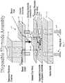
FIG. 1 is an exploded schematic view of an electrochemical cell assembly according to the invention including a disposable electrode.FIG. 2 is a top view of a masking for vapor deposition of the electrode onto a substrate.FIGS. 3a - 3c are schematic representations of a method for masking a disposable electrode of the invention.- Referring to
FIG. 1 , a flow-through electrochemical cell detector is illustrated including one embodiment of a disposable working electrode according the present invention. Most of the components of this cell can be similar to a conventional electrochemical cell such as the ED40 cell of Dionex Corporation, with the exception that the disposable working electrode structure replaces a generally permanent electrode structure which is periodically reconditioned as by polishing. - In general terms, the flow-through electrochemical cell includes a sample flow channel in contact with a working electrode. Sample analyte in a liquid eluent solution flows through the sample flow channel and from there through a reference electrode chamber. Electrode surface reactions are carried out on the working electrode, typically including an electrically conductive and electrochemically active material which is in direct contact with the sample solution flowing through the sample flow channel.
- Specifically referring to
FIG. 1 , in one embodiment of anelectrochemical cell assembly 10, a conventionalreference electrode block 12 defines a contained cylindricalreference electrode chamber 14 through which the sample solution flows passing through the sample flow channel. Another suitable conventional electrode is in the form of a counter orauxiliary electrode 16. - The basic function of the auxiliary electrode is to prevent the electrical current from running through the reference electrode. This is achieved by means of so-called three-electrode potentiostats. Seepages 47-48, 239-241, William R. LaCourse, Pulsed Electrochemical Detection in High-Performance Liquid Chromatography, John Wiley, New York 1997, pages 47-48 and 239-241.
- If the passage of the current through the reference is not minimized, oxidation or reduction of the reference material can take place (e.g. AgCl reduced back to silver or Ag oxidized to silver oxide) or change of chloride concentration in the junction solution which may result in a poor constancy of the reference potential. The three-electrode potentiostats were introduced in the 1950s. Prior to that only two-electrode cells were in general use for voltammetry (i.e. measurement of current while controlling the potential)
- As illustrated in
Fig. 1 , the sample flow channel in contact with the working electrode is defined by a gasket 18 which is retained in sealing relationship between the lower wall ofcounter electrode 16 and the upwardly facing wall of disposable workingelectrode structure 20 to be described hereinafter. Gasket 18 defines an interior cut-out forming a perimeter wall around sample flow channel 18a. The configuration of the sample flow channel 18a is defined by the thickness of gasket 18, and the length and width of the cut-out, preferably in the form of an elongated flow-through slot. As illustrated, the workingelectrode structure 20 includes a support substrate 20a, preferably formed of an organic polymer, and includes an electrically conductive and electrochemically active working electrode region 20b, preferable in the form of a thin layer, in a circular shape as illustrated. As will be described hereinafter, the working electrode region 20b is preferably formed by vapor deposition of an electrically conductive and electrochemically active material, directly or indirectly, onto substrate 20a. As used herein, "electrochemically active" means material suitable for facilitating the required electrochemical reactions for detection in electrochemical cells. - In the embodiment of
FIG. 1 , workingelectrode structure 20 also includes an electrically conductive contact region 20c, suitably also in the form of a circular disk, and an electrically conductive lead 20d interconnecting working electrode region 20b and contact region 20c. In a preferred embodiment, working electrode region 20b, contact region 20c and lead 20d are formed by vapor deposition of the same electrically conductive material directly or indirectly onto substrate 20a through a mask. As will be described hereinafter, an adhesion layer preferrably is first deposited onto an organic substrate to facilitate binding of the electrode material. Preferably the adhesion material is of the same configuration as regions 20b and 20c and lead 20d and is also formed by vapor deposition through a mask of substantially the same shape. - As in a conventional electrochemical cell, the assembly includes a working
electrode connection 22, suitably spring loaded and in electrical communication at one end of a potentiostat, including a voltage or current source, and at the other end in electrical contact with region 20c to establish an electrical connection with working electrode region 20b through lead 20d. - As illustrated, the working electrode region 20b is disposed in the sample flow channel 18a in direct contact with sample flowing therethrough. In an illustrated embodiment,
connection pin 22 and contact region 20c are disposed to the exterior of sample flow channel 18a out of fluid contact with liquid flowing through the flow channel. This has the advantage of simplicity. The working electrode, connector and contact pad are located in a planar arrangement on the same side of the polymeric substrate. This makes it possible to manufacture the entire working electrode in what is essentially a two-step deposition (e.g. with Ti and Au). - In contrast, the manufacturing of permanent electrodes requires many more steps: machining of a kel-F block, machining of a steel support plate, covering of a gold wire by a suitable insulating materials, machining of a Teflon ferrule for the liquid seal between the gold wire and the Kel F material, machining of the gold contact pad cylinder, insertion of the gold wire and of the contact pad into the opening in the Kel F material. Curing of the conductive polymer between the electrode wire and the contact pad cylinder. Sanding down the gold wire to the level of the KelF material. Machine lapping of the gold wire, hand-polishing of the gold wire. Of these multiple steps, the hand polishing is very person-dependent and notorious for its lack of reproducibility.
- The components are suitably held in the assembly under compression using a
holder block 24 which maintains gasket 18 andelectrode structure 20 in fluid sealing relationship. As illustrated, the compression is accomplished by the use ofconventional wing nuts 26 or other clamping means. In one alternative form, not shown, gasket 18 can be formed integral with or adhered tosubstrate 20 as by an adhesive bond therebetween forming an integral unit which can be readily removed from the cell and replaced by another integral unit. Alternatively, gasket 18 can be mounted to counterelectrode 16 or other support structure. In each of these or other possible configurations, a disposable electrode structure can be removed from the assembly and replaced alone or in combination with a gasket and support plate or holder block. - Gasket 18 typically is flexible with a thickness in the range of about 0.01 to 0.0005 inch consists of a fluoro polymer such as Teflon® or such polymeric materials as polyetherimide or nylon.
- A similar type of gasket can be used as is used in the ED40 electrochemical cell. Such a gasket suitably includes an elongate slot for flow channel 18a, suitably 0.5 to 10.0 mm, preferably 0.8 to 5 mm long. The channel width is suitably 0.1 to 3 mm, preferably 0.5 to 1.5 mm. The gaskets are suitably 0.005 to 0.5 mm, preferably 0.013 to 0.1 mm thick.
- As illustrated, the gasket can be held in place by bolts passing through openings in the gasket material at both ends of the gasket.
- For use with disposable electrodes it is advantageous to modify the outer shape of the ED40 cell gasket as illustrated in
Figure 1 . An elongated partial protrusion or tab covering the lead between the electrode and the contact pad improves the liquid seal. Also of advantage is to use thicker (>0.05 mm) and/or softer materials (PTFE) for gasketing of disposable electrodes. - In one embodiment, the gasket can also be made an integral part of the disposable electrode. The polymeric gasket can be permanently attached to the disposable electrode. This can be done either by oxygen plasma treatment of both surfaces followed by pressing the gasket against the electrode at room temperature. Alternatively, a permanent bonding of gaskets and electrodes can be achieved by using polyethylene coated polyester material of suitable thickness as a gasket.
After cutting the material to the proper gasketing shape, the gasket is pressed to the face of the disposable electrode at a suitable elevated temperature, usually about 140°C. - Typically, the sample containing separated analytes in an eluent solution flows through conventional fittings, not shown, from a chromatographic separator, such as a packed bed chromatography column upstream of the electrochemical cell to flow channel 18a. The sample solution flows through inlet tubing connected to a sample flow channel inlet, not shown, in the path illustrated by
arrows 28. As in the ED40 cell, the inlet can be formed by a pin hole opening throughcounter electrode 16 in the upstream end of flow channel 18a. The solution flows across flow channel 18a and exits through a sample flow channel outlet in the path illustrated schematically byarrows 30 and flows through a pin hole size opening, not shown, incounter electrode 16 intochamber 14 and exitschamber 14 through a fitting, not shown, through chamber outlet 32. - In another system, a conventional chemical or electrochemical suppressor is disposed between the electrochemical cell detector and the chromatography separator of an ion chromatography system.
- The working electrode region is disposed within flow channel 18a to contact the flowing sample in eluent solution therein. A preferred way to accomplish this and to provide electrical contact with
connector pin 22 is to space contact region 20c from working electrode region 20b and to interconnect them by lead 20d. This can be accomplished by the use of a mask which includes these three elements vapor deposited through the mask. In this configuration, the three elements are preferably in the form of thin film bound directly or indirectly to substrate 20a. - Referring to
FIG. 2 , a top view of amask 40 designed for vapor depositing multiple electrode region is illustrated. Mask includes alignment holes 41 to hold the screen in place and fixingscrew 42 together with a fixingbar 44. In one embodiment, themask 40 is prepared by wet etching of aluminum or stainless steel sheets. The electrical pattern is defined by openings in the mask. One way to vapor deposit the electrode region is by placing a sheet of polymeric substrate betweenmask 40 and a stainless steel plate, not shown. The mask includes working electrode opening 40b which defines working electrode region 20b, larger contact region 40c which defines contact region 20c and slot opening 40d which defines lead 20d. Suitable mask materials include metal (e.g. stainless steel, molybdenum), glass, quartz and silicon. - The metallic pattern may be prepared by conventional micro fabrication techniques used in semi-conduction manufacture as described, for example, inM. Madou, Fundamentals of Microfabrication, CRC Press, New York, 1997. These methods include but are not limited to physical vapor deposition (PVD) and chemical vapor deposition (CVD).
- Preferably, before depositing the electrode region, an adhesion layer is deposited using the
mask 40. This method is illustrated schematically inFIGS. 3a-c . Referring toFIG. 3a , a thin film of the adhesion layer 50, illustrated as the darkened region 50 inFIG. 3b , is sputtered through opening 40b, 40c, 40d andmask 40 as by sputtering using a high vacuum with Ar plasma. Such a technique is illustrated inM. Madou, Chapter 2, p. 60, Figure 2.8 of Fundamentals of Microfabrication (CRC, 1997). Thereafter, as illustrated inFIG. 3c the mask is maintained in place. A suitable electrode material for direct contact with the sample in flow channel 18b is vapor deposited as a secondthin film 52 onto a surface of the adhesion layer 50. The advantage of the adhesion layer is that it improves the cohesion between the electrode layer and the underlying substrate for any substrate, preferably an organic polymer material. - Suitably the adhesion layer is formed of a material such as titanium, tungsten, chromium and alloys of these materials. A titanium or tungsten titanium alloy adhesion layer is particularly effective to improve an adhesion of a metallic working electrode layer to the polymeric substrate. A typical thickness for the adhesion layer 50 is about 50 Å to 5,000 Å.
- A suitable electrode material in region 20a is a metal, preferably a noble metal such as gold, platinum, copper or silver, or alloys thereof, although gold is the most frequently used one. In addition, a non-metallic electrode may be used for region 20b such as a carboneous material (e.g. glassy carbon, graphite or carbon paste) in combination with an adhesion layer such as titanium. Similar sputtering techniques would be employed. A typical thickness for the electrode material of
layer 52 is about 100 Å to 10,000 Å. - A suitable top view configuration of working electrode region 20b is circular with a diameter of about 0.1 to 3 mm, and suitably about 0.5 to 2.0 mm, preferably about 1 mm. A suitable contact region 20c is larger because of the need to accommodate different types of useful contacting arrangements and to ensure good contact with
pin 22. Substrate 28 is preferably of a polymeric material with a thickness in the range of about 5.08 x 10⁻²m to 50.8 x 10⁻²m (0.002 to 0.02 inches). It is preferably flexible for forming a good seal with gasket 18. Suitably, the polymeric material can be a polyester (such as polyethylene, terephthalate or polyethylene naphthalate), polycarbonate, polyolefin, polyimide or polyetherimide. Preferably, the polymeric material is a polyester (PEN or PET-type) or a polycarbonate.- Other alternative structures for the disposable working electrodes include different geometrical shapes of the working electrode area such as triangle, square or rectangle. Several possible arrangements relative to the flow path are possible for each of the non-circular geometries of the working electrodes. Also possible are comb-like patterns of two or more "finger" shaped electrodes connected to the same lead as the circular electrodes but protruding into the flow path either in a parallel or in radial fashion. Also feasible are intercalated electrodes or two comb-like electrode patterns protruding into the flow path from the opposing sides.
- The electronics connecting the system can be the ones conventionally used in a Dionex ED40 or 50 electrochemical cell. A true reference electrode, e.g., Ag/AgCl wire immersed in a reference solution enclosed by suitable diaphragm or a glass membrane may be employed.
- In one embodiment of the invention, microfabricated electrodes are used in conjunction with a salt bridge-equipped true reference electrode. The combination pH/Ag/AgCl electrode represents an improvement even over a "true" reference electrode. An integral part of the detection mechanism is a cyclical creation of a catalytic gold oxide layer on the working electrode's surface. The IP AD mode freshly creates and removes the amino acid-detection-enabling gold oxide layer with a frequency of 1 Hz or higher. The creation of gold oxide is pH dependent and in consequence different levels of oxidation current are generated as a detection background at different pH. With a Ag/AgCl reference electrode alone, any change of eluent pH, such as during a chromatographic mobile phase gradient, results in a strongly sloping chromatographic baseline. With the glass-membrane equipped true-reference electrode such as pH/Ag/AgCl the reference potential changes with pH in an identical fashion as the rate of gold oxide formation. The pH-connected change of the reference potential is thus providing an automatic compensation of the change of the oxidation current. The resulting baseline during a pH gradient is then completely flat.
- In one embodiment of the invention, microfabricated electrodes are used with a pH compensated reference potential (i.e. true reference electrode, salt bridge, glass membrane).
- The electrochemical cell of the present invention can be used in any application in which ED40 or ED50 cell is used. Thus, it can be used to detect separated amino acids, sugars, amino sugars, amines, amino thiols or the like. One of the advantages of the working electrode and reference electrode of the present invention is that they are capable of off-setting the change of pH and thus to eliminate excessive base line shifts. This is because of the built-in pH-related compensation of oxidation currents.
- An important advantage of the disposable electrode is that it can be readily replaced after a single day or multiple day use at low expense before loss of performance of the cell.
- The disposable electrodes of the present invention are compatible with a commercial low dead volume electrochemical cell. This enables use of a true reference or pH based reference potential.
- A variety of samples were analyzed with different protocols using an electrochemical cell with a disposable electrode according to the present invention. The chromatograms from such experiments were very comparable to ones performed using the ED40 cell.
- In order to more clearly illustrate the present invention, the following examples of its practice are presented.
- This illustrates a method for forming a sputtered thin film of titanium and gold on a polymeric substrate according to the invention.
- Polymeric film substrates obtained from Du Pont or GE were cleaned of all particles on their surface by blowing off with air, rinsed successively with water, alcohol and then dried in air. After punching the holes required for mounting the masks on top of the film, the polymeric substrates were put on top of a stainless steel base plate. We then placed first a thinner stainless steel mask and then a thicker stainless steel mask on the exposed side of the polymeric film. The patterns of the thinner mask is shown in
Figure 2 . The thinner mask defines the shape of the electrode, connection lead and contact pad. The thicker mask, not shown, is used for keeping the thinner mask flat, completely co-planar and in close contact with the polymeric film. At the same time, the thicker mask has open cutout areas, thus providing the structural integrity without interference with the plasma during the sputtering of titanium and gold. The polymeric films are sandwiched tightly between the two masks and the supporting base plate. The whole assembly is being held together by bars and screws. The bars are positioned on top of the two masks. - The polymeric substrates assembled with masks are placed in the sputtering chamber. A suitable vacuum is applied for 12 hours (overnight) to reach the vacuum required for sputtering (at least 40 mTorr). The water adsorbed inside the polymer is slowly removed from the chamber during that time. To initiate the deposition, the substrate remains enclosed in a low-pressure gas atmosphere (ca. 10 mTorr of argon). For RF plasma deposition the substrate is connected as anode and the metal source for deposition (target) is connected as cathode. A suitable RF frequency is within the range of 12-14 mHz. The suitable range of RF power is in the range of 1 to 2 kW. The deposition rate is different for different metals. For the same frequency and power of the RF field, titanium deposition is ca. 4.7 times slower than the deposition of gold (see for example Table 3.8, page 100, M. Madou, Fundamentals of Micromachining). The RF field generated between the substrate and target is the sole heating source during the metal deposition. The temperature of the polymeric substrate never exceeds the range of 50-70°C.
- A titanium layer is sputtered first to promote adhesion of gold films to polymeric substrates. A typical thickness of the first metallic layer is 50 to 1000 Å. The layer of titanium is the only adhesion-promoting agent utilized in our process. There are no other adhesives being utilized to promote adhesion of gold layer to the polymeric substrate. The second layer (Au) is usually 100 to 5000 Å thick. The sputtering time varies from system to system because the coating rate depends on the power of the radio frequency (plasma source), the distance between the polymeric film and target (source of metal being deposited) and others.
- Assembling a suitable cell
- (1) Remove the ED40 cell body made of titanium from the stainless steel box serving as a Faraday Cage/electrode mounting container and unscrew the steel cylinder holder for the reference electrode.
- (2) Verify that a black O ring (Viton) is in place in the lower part of the reference electrode chamber.
Insert a pH/Ag/AgCl reference electrode (glass cylinder) into the reference electrode chamber of the cell body. - (3) Install the steel cylinder holding the reference electrode in pre-defined position inside the reference electrode chamber.
- (4) Connect the lead wires of the reference electrode to the "pH" and "Ag" pins of the pre-amplifier board.
- (5) The white cable of the working electrode connection remains connected to the two "WE" pins.
- (6) Unscrew the two winged screws and remove the permanent working electrode from the cell body.
- (7) Remove the standard cell gasket and replace it by a cell gasket for use with disposable electrodes.
- (8) Match the two holes of the disposable electrode unit (outside dimensions 2.5 x 3 cm) to the two posts protruding from the cell body. The two openings of the disposable electrode match the distance between the two posts (2 cm). Slide the disposable electrode all the way to the bottom of the two alignment posts. This positions the working electrode correctly inside the flow path defined by the gasket cutout. Make sure that the metallized side of the disposable electrode unit faces the electrode cell body and the gasket. The correct position of the working electrode can be verified through the transparent polyester substrate of the disposable electrode. The correct orientation of the disposable working electrode is indicated by the titanium color (not gold) being visible through the polyester when the unit is in the position close to the cell body.
- (9) Slide the permanent electrode (or alternatively a less expensive holder block) onto the two posts pressing the disposable electrode against the cell body. Check visually the presence of the cell gasket and the correct contact between contact pin and contact pad.
- (10) Mount the two winged nuts.
- (11) Make liquid connections to and from the electrode cell.
- (12) Slide the steel mounting box/Faraday Cage over the assembled cell.
- (13) Connect the assembled cell to the electronic unit of the ED40 detector.
- (14) Start the pump and wait until you see the first drops coming out of the outlet capillary.
- (15) Check the pH readout on the screen of the ED40 electronic unit.
- (16) Apply a suitable detection potential or detection waveform.
Claims (23)
- A flow-through electrochemical cell assembly for a chromatography system comprising(a) a perimeter wall defining a sample flow channel including an inlet and an outlet,(b) a sample inlet line in fluid communication with said sample flow channel inlet,(c) a sample outlet line providing fluid communication between said sample flow channel outlet and a remote reference electrode, and(d) a disposable working electrode structure comprising an electrically conductive and electrochemically active working electrode region bound as a layer, directly or indirectly, to an electrically insulating substrate surface, said substrate surface being in fluid-sealing relationship with said sample flow channel, said working electrode region being in fluid communication with said sample flow channel, said working electrode structure being readily removable from said electrochemical cell assembly.
- The flow-through electrochemical cell assembly of claim 1, wherein at least a portion of the substrate surface is exposed to the sample flow channel.
- The flow-through electrochemical cell assembly of Claim 1 in which said working electrode structure further comprises an electrically conductive contact region bound as a layer, directly or indirectly, to said substrate surface and an electrically conductive lead providing an electric path between said working electrode region and said contact region, said contact region being bound to said substrate surface out of fluid contact with said sample flow channel.
- The flow-through electrochemical cell assembly of Claim 3 further comprising an electrically conductive connection pin having a first end in removable contact with said contact region and a second end adapted for electrical connection to a power source.
- The flow-through electrochemical cell assembly of Claim 1 in which said perimeter wall comprises a gasket forming a fluid-tight seal at the periphery of said sample flow channel.
- The flow-through electrochemical cell assembly of Claim 1 in which said working electrode region is exposed directly to said sample flow channel, without an intermediate layer.
- The flow-through electrochemical cell assembly of Claims 1 or 2 in which said working electrode region is between about 100 Å and 10,000 Å thick.
- The flow-through electrochemical cell assembly of Claim 1 in which said working electrode region is formed by vapor deposition of electrically conductive and electrochemically active material, directly or indirectly, onto said substrate
- The flow-through electrochemical cell assembly of Claim 1 in which said substrate comprises an organic polymer.
- The flow-through electrochemical cell assembly of Claim 9 in which said organic polymer is selected from the group consisting of polyester, polycarbonate, polyolefin, polyimide and polyetherimide.
- The flow-through electrochemical cell assembly of Claim 1 in which said working electrode region comprises a metal or a carbonaceous material.
- The flow-through electrochemical cell assembly of Claim 1 in which said working electrode region is bound through an intermediate adhesion layer to said substrate.
- The flow-through electrochemical cell assembly of Claim 12 in which said adhesion layer is formed by vapor deposition onto said substrate.
- The flow-through electrochemical cell assembly of Claim 12 in which said adhesion layer is between about 50 Å and 5000 Å thick.
- The flow-through electrochemical cell assembly of Claim 12 in which said adhesion layer is formed of a material selected from the group consisting of titanium, tungsten, chromium, and alloys thereof.
- The flow-through electrochemical cell of Claim 1 in which said sample flow inlet is in fluid communication with a liquid chromatographic separator or flow injection analysis apparatus.
- A method for making a disposable working electrode structure and sample flow channel for use in an electrochemical cell assembly for a chromatography system, said method comprising:(a) vapor depositing electrically conductive and electrochemically active material, directly or indirectly, onto an organic polymer substrate through a mask to form a pattern of a working electrode region, and(b) forming a fluid seal between said working electrode region and a perimeter wall to define a fluid sample flow channel with said working electrode region in direct fluid contact with said fluid sample flow channel.
- The method of claim 17, wherein at least a portion of the organic polymer substrate is exposed to the sample flow channel.
- The method of Claim 17 in which said vapor deposition is through said mask which mask forms a pattern of an electrically conductive lead interconnecting said working electrode and an electrically conductive contact region forming said disposable working electrode structure.
- The method of Claim 17 further comprising, before step (a), vapor depositing an adhesion layer onto said organic polymer substrate through a mask, wherein step (a) is performed by vapor depositing said electrically conductive material and electrochemically active onto said adhesion layer.
- The method of Claim 20 in which said adhesion layer is formed of a material selected from the group consisting of titanium, tungsten, chromium, and alloys thereof.
- The method of Claim 17 in which said organic polymer is selected from the group consisting of polyester, polycarbonate, polyolefin, polyimide and polyetherimide.
- A chromatography system comprising a flow-through electrochemical cell assembly according to any one of claims 1 to 16.
Applications Claiming Priority (5)
| Application Number | Priority Date | Filing Date | Title |
|---|---|---|---|
| US34213701P | 2001-12-18 | 2001-12-18 | |
| US342137P | 2001-12-18 | ||
| US81691 | 2002-02-20 | ||
| US10/081,691US6783645B2 (en) | 2001-12-18 | 2002-02-20 | Disposable working electrode for an electrochemical cell |
| PCT/US2002/040281WO2003054985A2 (en) | 2001-12-18 | 2002-12-16 | Disposable working electrode for an electrochemical cell |
Publications (2)
| Publication Number | Publication Date |
|---|---|
| EP1602138A2 EP1602138A2 (en) | 2005-12-07 |
| EP1602138B1true EP1602138B1 (en) | 2018-01-24 |
Family
ID=26765837
Family Applications (1)
| Application Number | Title | Priority Date | Filing Date |
|---|---|---|---|
| EP02792413.3ARevokedEP1602138B1 (en) | 2001-12-18 | 2002-12-16 | Disposable working electrode for an electrochemical cell |
Country Status (6)
| Country | Link |
|---|---|
| US (2) | US6783645B2 (en) |
| EP (1) | EP1602138B1 (en) |
| JP (2) | JP4778680B2 (en) |
| AU (2) | AU2002357869A1 (en) |
| CA (1) | CA2465810C (en) |
| WO (1) | WO2003054985A2 (en) |
Families Citing this family (24)
| Publication number | Priority date | Publication date | Assignee | Title |
|---|---|---|---|---|
| ES2709991T3 (en) | 2003-08-21 | 2019-04-22 | Agamatrix Inc | Method and apparatus for the analysis of electrochemical properties |
| JP2010512533A (en)* | 2006-12-12 | 2010-04-22 | コーニンクレッカ フィリップス エレクトロニクス エヌ ヴィ | Electrochemical sensor device and method for producing the electrochemical sensor device |
| AU2008217579A1 (en)* | 2007-02-20 | 2008-08-28 | Oxford Nanopore Technologies Limited | Formation of lipid bilayers |
| GB2447043A (en)* | 2007-02-20 | 2008-09-03 | Oxford Nanolabs Ltd | Lipid bilayer sensor system |
| GB0724736D0 (en) | 2007-12-19 | 2008-01-30 | Oxford Nanolabs Ltd | Formation of layers of amphiphilic molecules |
| GB201202519D0 (en) | 2012-02-13 | 2012-03-28 | Oxford Nanopore Tech Ltd | Apparatus for supporting an array of layers of amphiphilic molecules and method of forming an array of layers of amphiphilic molecules |
| US9063073B2 (en) | 2012-04-04 | 2015-06-23 | Wisconsin Alumni Research Foundation | Solid working electrode with replaceable tip |
| GB201313121D0 (en) | 2013-07-23 | 2013-09-04 | Oxford Nanopore Tech Ltd | Array of volumes of polar medium |
| US9362600B2 (en) | 2013-09-11 | 2016-06-07 | King Fahd University Of Petroleum And Minerals | Cell with reusable and disposable assemblies for simultaneous electrochemical and EPR measurements |
| GB201418512D0 (en) | 2014-10-17 | 2014-12-03 | Oxford Nanopore Tech Ltd | Electrical device with detachable components |
| US9658190B2 (en)* | 2014-12-18 | 2017-05-23 | Genia Technologies, Inc. | Printed electrode |
| GB201611770D0 (en) | 2016-07-06 | 2016-08-17 | Oxford Nanopore Tech | Microfluidic device |
| US10877005B2 (en) | 2016-12-20 | 2020-12-29 | Dionex Corporation | Method of measuring an analyte with a reductive detection waveform |
| GB2568895B (en) | 2017-11-29 | 2021-10-27 | Oxford Nanopore Tech Ltd | Microfluidic device |
| US20200031857A1 (en) | 2018-07-30 | 2020-01-30 | Dionex Corporation | Anion exchange stationary phases based on a polyalkylpolyamine polymer layer |
| WO2020081168A2 (en)* | 2018-09-10 | 2020-04-23 | Board Of Regents Of The University Of Texas System | Ion detection devices for use in ion chromatography |
| CN109781923B (en)* | 2018-12-13 | 2021-06-22 | 日照海关综合技术服务中心 | Method for simultaneously and rapidly determining multiple amino acids and sugars in soy sauce |
| CN113574381B (en) | 2019-03-12 | 2025-08-26 | 牛津纳米孔科技公开有限公司 | Nanopore sensing devices, components, and operating methods |
| US11453001B2 (en) | 2020-01-29 | 2022-09-27 | International Business Machines Corporation | Microfluidic chips with integrated electronic sensors |
| US20210396705A1 (en)* | 2020-06-17 | 2021-12-23 | Board Of Trustees Of Michigan State University | Microfluidic respirometry of metabolic functions in biological samples |
| CN115989410A (en) | 2020-07-17 | 2023-04-18 | 牛津纳米孔科技公开有限公司 | Nanopore Sensing Device |
| US11977046B2 (en) | 2020-12-31 | 2024-05-07 | Dionex Corporation | Electrochemical cell configured to have a dynamically renewed electrode |
| US11802857B2 (en) | 2021-12-08 | 2023-10-31 | Dionex Corporation | Monitoring and preventing suppressor failures |
| US20240201146A1 (en)* | 2022-12-19 | 2024-06-20 | Dionex Corporation | Disposable thin-film platinum hydrogen reference electrode |
Citations (6)
| Publication number | Priority date | Publication date | Assignee | Title |
|---|---|---|---|---|
| GB2122354A (en) | 1982-06-18 | 1984-01-11 | Gas Measurement Instr Limited | Electrochemical cells |
| US5131999A (en) | 1990-01-16 | 1992-07-21 | The National University Of Singapore | Voltammetric detector for flow analysis |
| US5437999A (en) | 1994-02-22 | 1995-08-01 | Boehringer Mannheim Corporation | Electrochemical sensor |
| DE19537506C1 (en) | 1995-09-26 | 1997-03-27 | Ufz Leipzighalle Gmbh | Flow rate measuring cell for biosensor |
| US5755953A (en) | 1995-12-18 | 1998-05-26 | Abbott Laboratories | Interference free biosensor |
| US20010035349A1 (en) | 2000-03-28 | 2001-11-01 | Nec Corporation | Measuring device for liquid sample and method for measuring liquid sample |
Family Cites Families (36)
| Publication number | Priority date | Publication date | Assignee | Title |
|---|---|---|---|---|
| US3654585A (en)* | 1970-03-11 | 1972-04-04 | Brooks Research And Mfg Inc | Coordinate conversion for the testing of printed circuit boards |
| US4056636A (en)* | 1975-04-22 | 1977-11-01 | Mueller Hans | Process for the conversion of starch and protein-containing cellulosic waste products into nutrients richer in proteins |
| JPS5961772A (en)* | 1982-09-28 | 1984-04-09 | ザ・イエロ−・スプリングス・インストルメント・カンパニ−・インコ−ポレ−テツド | Liquid chromatograph enzyme electrode detector |
| CA1226036A (en)* | 1983-05-05 | 1987-08-25 | Irving J. Higgins | Analytical equipment and sensor electrodes therefor |
| US4640289A (en)* | 1983-11-14 | 1987-02-03 | Minnesota Mining And Manufacturing Company | Biomedical electrode |
| US4781798A (en)* | 1985-04-19 | 1988-11-01 | The Regents Of The University Of California | Transparent multi-oxygen sensor array and method of using same |
| US4938860A (en)* | 1985-06-28 | 1990-07-03 | Miles Inc. | Electrode for electrochemical sensors |
| US4716071A (en)* | 1985-08-22 | 1987-12-29 | Harris Corporation | Method of ensuring adhesion of chemically vapor deposited oxide to gold integrated circuit interconnect lines |
| US4710403A (en) | 1986-05-05 | 1987-12-01 | Minnesota Mining And Manufacturing Company | Metallized polymers |
| JPH01250860A (en)* | 1988-03-31 | 1989-10-05 | Shimadzu Corp | Analyzer system for alcohol drinks |
| US5234566A (en)* | 1988-08-18 | 1993-08-10 | Australian Membrane And Biotechnology Research Institute Ltd. | Sensitivity and selectivity of ion channel biosensor membranes |
| US4936860A (en)* | 1988-09-23 | 1990-06-26 | Swanson Alfred B | Metal scaphoid implant |
| US5104820A (en)* | 1989-07-07 | 1992-04-14 | Irvine Sensors Corporation | Method of fabricating electronic circuitry unit containing stacked IC layers having lead rerouting |
| DE4027390C2 (en)* | 1990-08-30 | 1994-11-03 | Boehringer Ingelheim Kg | Propellant-free inhalation device |
| US5521425A (en)* | 1990-12-21 | 1996-05-28 | Hewlett-Packard Company | Tape automated bonded (TAB) circuit |
| DE4142534A1 (en)* | 1990-12-28 | 1992-07-09 | Sawafuji Electric Co Ltd | ROTATIONAL COMPRESSOR CONTROL SYSTEM FOR AN ELECTRIC COOLING UNIT |
| US5324322A (en) | 1992-04-20 | 1994-06-28 | Case Western Reserve University | Thin film implantable electrode and method of manufacture |
| US5338430A (en)* | 1992-12-23 | 1994-08-16 | Minnesota Mining And Manufacturing Company | Nanostructured electrode membranes |
| EP0612538A3 (en) | 1993-02-22 | 1995-04-05 | Cardiac Pacemakers Inc | Metallized, implantable cardiac electrode. |
| CH685458A5 (en) | 1993-03-01 | 1995-07-14 | Disetronic Ag | Sensor array for selective detection or measurement of at least one material component in an aqueous solution. |
| JP2882619B2 (en)* | 1993-03-25 | 1999-04-12 | 日本碍子株式会社 | Non-ceramic insulator |
| GB9412789D0 (en)* | 1994-06-24 | 1994-08-17 | Environmental Sensors Ltd | Improvements to electrodes |
| US5574627A (en)* | 1995-07-24 | 1996-11-12 | At&T Global Information Solutions Company | Apparatus for preventing the formation of condensation on sub-cooled integrated circuit devices |
| US5989409A (en) | 1995-09-11 | 1999-11-23 | Cygnus, Inc. | Method for glucose sensing |
| JP3377016B2 (en)* | 1996-01-26 | 2003-02-17 | 矢崎総業株式会社 | Limit current type oxygen sensor for measuring oxygen concentration in exhaust gas |
| US6110354A (en) | 1996-11-01 | 2000-08-29 | University Of Washington | Microband electrode arrays |
| US5928142A (en) | 1996-12-17 | 1999-07-27 | Ndm, Inc. | Biomedical electrode having a disposable electrode and a reusable leadwire adapter that interfaces with a standard leadwire connector |
| US5921925A (en) | 1997-05-30 | 1999-07-13 | Ndm, Inc. | Biomedical electrode having a disposable electrode and a reusable leadwire adapter that interfaces with a standard leadwire connector |
| DE19741878A1 (en) | 1997-09-23 | 1999-03-25 | Hoechst Diafoil Gmbh | Multi-layer, biaxially oriented polyester film, process for its production and its use |
| US6001239A (en)* | 1998-09-30 | 1999-12-14 | Mercury Diagnostics, Inc. | Membrane based electrochemical test device and related methods |
| DE19801344C2 (en) | 1998-01-16 | 2002-01-17 | Trace Biotech Ag | Flow analysis cell and associated layer sensor |
| US6054676A (en)* | 1998-02-09 | 2000-04-25 | Kryotech, Inc. | Method and apparatus for cooling an integrated circuit device |
| US6134461A (en) | 1998-03-04 | 2000-10-17 | E. Heller & Company | Electrochemical analyte |
| US6277117B1 (en) | 1998-10-23 | 2001-08-21 | Sherwood Services Ag | Open vessel sealing forceps with disposable electrodes |
| US6258229B1 (en) | 1999-06-02 | 2001-07-10 | Handani Winarta | Disposable sub-microliter volume sensor and method of making |
| US6287451B1 (en) | 1999-06-02 | 2001-09-11 | Handani Winarta | Disposable sensor and method of making |
- 2002
- 2002-02-20USUS10/081,691patent/US6783645B2/ennot_activeExpired - Lifetime
- 2002-12-16AUAU2002357869Apatent/AU2002357869A1/ennot_activeAbandoned
- 2002-12-16CACA2465810Apatent/CA2465810C/ennot_activeExpired - Lifetime
- 2002-12-16EPEP02792413.3Apatent/EP1602138B1/ennot_activeRevoked
- 2002-12-16WOPCT/US2002/040281patent/WO2003054985A2/enactiveApplication Filing
- 2002-12-16JPJP2003555603Apatent/JP4778680B2/ennot_activeExpired - Lifetime
- 2004
- 2004-07-07USUS10/886,876patent/US20040256216A1/ennot_activeAbandoned
- 2009
- 2009-03-27AUAU2009201217Apatent/AU2009201217B2/ennot_activeExpired
- 2009-11-24JPJP2009266592Apatent/JP2010071994A/enactivePending
Patent Citations (6)
| Publication number | Priority date | Publication date | Assignee | Title |
|---|---|---|---|---|
| GB2122354A (en) | 1982-06-18 | 1984-01-11 | Gas Measurement Instr Limited | Electrochemical cells |
| US5131999A (en) | 1990-01-16 | 1992-07-21 | The National University Of Singapore | Voltammetric detector for flow analysis |
| US5437999A (en) | 1994-02-22 | 1995-08-01 | Boehringer Mannheim Corporation | Electrochemical sensor |
| DE19537506C1 (en) | 1995-09-26 | 1997-03-27 | Ufz Leipzighalle Gmbh | Flow rate measuring cell for biosensor |
| US5755953A (en) | 1995-12-18 | 1998-05-26 | Abbott Laboratories | Interference free biosensor |
| US20010035349A1 (en) | 2000-03-28 | 2001-11-01 | Nec Corporation | Measuring device for liquid sample and method for measuring liquid sample |
Non-Patent Citations (4)
| Title |
|---|
| CONCHESO-SUÄREZ ET AL.: "Electrochemical detector based on a gold band for flow systems", QUIM. ANAL., vol. 17, 1998, pages 35 - 38, XP055526154 |
| NEUFELD ET AL.: "A micro flow injection electrochemical biosensor for organophosphorus pesticides", BIOSENSORS & BIOELECTRONICS, vol. 15, 2000, pages 323 - 329, XP055526170 |
| WANG ET AL.: "Micromachined electrophoresis chips with thick-film electrochemical detectors", ANAL CHEM, vol. 71, 1999, pages 5436 - 5440, XP000902375 |
| ZEN ET AL.: "Disposable clay-coated screen-printed electrode for amitrole analysis", ANAL CHIM ACTA, vol. 449, 10 December 2001 (2001-12-10), pages 95 - 102, XP055526167 |
Also Published As
| Publication number | Publication date |
|---|---|
| AU2009201217A1 (en) | 2009-04-23 |
| US20040256216A1 (en) | 2004-12-23 |
| JP4778680B2 (en) | 2011-09-21 |
| AU2009201217B2 (en) | 2012-02-09 |
| WO2003054985A3 (en) | 2005-10-06 |
| WO2003054985A2 (en) | 2003-07-03 |
| CA2465810C (en) | 2011-08-02 |
| CA2465810A1 (en) | 2003-07-03 |
| AU2002357869A1 (en) | 2003-07-09 |
| JP2010071994A (en) | 2010-04-02 |
| US20030111340A1 (en) | 2003-06-19 |
| EP1602138A2 (en) | 2005-12-07 |
| US6783645B2 (en) | 2004-08-31 |
| JP2005519262A (en) | 2005-06-30 |
Similar Documents
| Publication | Publication Date | Title |
|---|---|---|
| AU2009201217B2 (en) | Disposable working electrode for an electochemical cell | |
| KR100340174B1 (en) | Electrochemical Biosensor Test Strip, Fabrication Method Thereof and Electrochemical Biosensor | |
| Voegel et al. | Electrochemical detection in capillary electrophoresis | |
| US5399256A (en) | Electrochemical detector cell | |
| US6878255B1 (en) | Microfluidic devices with thick-film electrochemical detection | |
| US7740746B2 (en) | Disposable electrochemical sensor strip | |
| US20040256228A1 (en) | Structure and manufacturing method of disposable electrochemical sensor strip | |
| Norouzi et al. | Fast monitoring of nano‐molar level of gentamycin by fast Fourier transform continuous cyclic voltammetry in flowing solution | |
| Voegel et al. | Integrated capillary electrophoresis/electrochemical detection with metal film electrodes directly deposited onto the capillary tip | |
| Gunasingham et al. | Hydrodynamic voltammetry in continuous-flow analysis | |
| US6682647B1 (en) | Bismuth-based electrochemical stripping analysis | |
| CA2625833A1 (en) | Analyte sensor and method of making it | |
| EP1845371A1 (en) | Electrochemical sensor strip and manufacturing method thereof | |
| US5552032A (en) | Solid state ion selective electrode and method of using the same | |
| You et al. | Applications of microelectrodes in capillary electrophoresis/electrochemical detection | |
| US5174883A (en) | Ultramicroelectrode ensembles | |
| WO2004023094A2 (en) | Electrochemical analytical apparatus and method of using the same | |
| JPH05126782A (en) | Measuring electrode and manufacturing method thereof | |
| Jin et al. | A new capillary electrophoresis end‐column amperometric detection system without the need for capillary/electrode alignment | |
| WO2021229222A1 (en) | Electrochemical sensing | |
| EP1304567A2 (en) | Electrochemical sensors having non-porous working electrode | |
| US5547553A (en) | Mercury thread electrode | |
| EP1634066A1 (en) | Structure and manufacturing method of disposable electrochemical sensor strip | |
| US3669864A (en) | Polarographic electrode apparatus and method | |
| Mohammadzadeh et al. | Fabrication and Characterization of a Low-Cost Micro-Volume Electrochemical Cell Using PCB for Electroanalytical Applications |
Legal Events
| Date | Code | Title | Description |
|---|---|---|---|
| PUAI | Public reference made under article 153(3) epc to a published international application that has entered the european phase | Free format text:ORIGINAL CODE: 0009012 | |
| 17P | Request for examination filed | Effective date:20040510 | |
| AK | Designated contracting states | Kind code of ref document:A2 Designated state(s):AT BE BG CH CY CZ DE DK EE ES FI FR GB GR IE IT LI LU MC NL PT SE SI SK TR | |
| REG | Reference to a national code | Ref country code:HK Ref legal event code:DE Ref document number:1077125 Country of ref document:HK | |
| 17Q | First examination report despatched | Effective date:20090903 | |
| GRAP | Despatch of communication of intention to grant a patent | Free format text:ORIGINAL CODE: EPIDOSNIGR1 | |
| INTG | Intention to grant announced | Effective date:20160511 | |
| REG | Reference to a national code | Ref country code:HK Ref legal event code:WD Ref document number:1077125 Country of ref document:HK | |
| TPAC | Observations filed by third parties | Free format text:ORIGINAL CODE: EPIDOSNTIPA | |
| STAA | Information on the status of an ep patent application or granted ep patent | Free format text:STATUS: GRANT OF PATENT IS INTENDED | |
| TPAA | Information related to observations by third parties modified | Free format text:ORIGINAL CODE: EPIDOSCTIPA | |
| GRAJ | Information related to disapproval of communication of intention to grant by the applicant or resumption of examination proceedings by the epo deleted | Free format text:ORIGINAL CODE: EPIDOSDIGR1 | |
| STAA | Information on the status of an ep patent application or granted ep patent | Free format text:STATUS: EXAMINATION IS IN PROGRESS | |
| INTC | Intention to grant announced (deleted) | ||
| GRAS | Grant fee paid | Free format text:ORIGINAL CODE: EPIDOSNIGR3 | |
| STAA | Information on the status of an ep patent application or granted ep patent | Free format text:STATUS: GRANT OF PATENT IS INTENDED | |
| GRAP | Despatch of communication of intention to grant a patent | Free format text:ORIGINAL CODE: EPIDOSNIGR1 | |
| INTG | Intention to grant announced | Effective date:20170721 | |
| GRAA | (expected) grant | Free format text:ORIGINAL CODE: 0009210 | |
| STAA | Information on the status of an ep patent application or granted ep patent | Free format text:STATUS: THE PATENT HAS BEEN GRANTED | |
| AK | Designated contracting states | Kind code of ref document:B1 Designated state(s):AT BE BG CH CY CZ DE DK EE ES FI FR GB GR IE IT LI LU MC NL PT SE SI SK TR | |
| REG | Reference to a national code | Ref country code:GB Ref legal event code:FG4D | |
| REG | Reference to a national code | Ref country code:CH Ref legal event code:EP Ref country code:CH Ref legal event code:NV Representative=s name:RENTSCH PARTNER AG, CH | |
| REG | Reference to a national code | Ref country code:AT Ref legal event code:REF Ref document number:966250 Country of ref document:AT Kind code of ref document:T Effective date:20180215 | |
| REG | Reference to a national code | Ref country code:IE Ref legal event code:FG4D Ref country code:NL Ref legal event code:FP | |
| REG | Reference to a national code | Ref country code:DE Ref legal event code:R096 Ref document number:60249286 Country of ref document:DE | |
| REG | Reference to a national code | Ref country code:AT Ref legal event code:MK05 Ref document number:966250 Country of ref document:AT Kind code of ref document:T Effective date:20180124 | |
| PG25 | Lapsed in a contracting state [announced via postgrant information from national office to epo] | Ref country code:CY Free format text:LAPSE BECAUSE OF FAILURE TO SUBMIT A TRANSLATION OF THE DESCRIPTION OR TO PAY THE FEE WITHIN THE PRESCRIBED TIME-LIMIT Effective date:20180124 Ref country code:ES Free format text:LAPSE BECAUSE OF FAILURE TO SUBMIT A TRANSLATION OF THE DESCRIPTION OR TO PAY THE FEE WITHIN THE PRESCRIBED TIME-LIMIT Effective date:20180124 Ref country code:FI Free format text:LAPSE BECAUSE OF FAILURE TO SUBMIT A TRANSLATION OF THE DESCRIPTION OR TO PAY THE FEE WITHIN THE PRESCRIBED TIME-LIMIT Effective date:20180124 | |
| PG25 | Lapsed in a contracting state [announced via postgrant information from national office to epo] | Ref country code:GR Free format text:LAPSE BECAUSE OF FAILURE TO SUBMIT A TRANSLATION OF THE DESCRIPTION OR TO PAY THE FEE WITHIN THE PRESCRIBED TIME-LIMIT Effective date:20180425 Ref country code:AT Free format text:LAPSE BECAUSE OF FAILURE TO SUBMIT A TRANSLATION OF THE DESCRIPTION OR TO PAY THE FEE WITHIN THE PRESCRIBED TIME-LIMIT Effective date:20180124 Ref country code:SE Free format text:LAPSE BECAUSE OF FAILURE TO SUBMIT A TRANSLATION OF THE DESCRIPTION OR TO PAY THE FEE WITHIN THE PRESCRIBED TIME-LIMIT Effective date:20180124 Ref country code:BG Free format text:LAPSE BECAUSE OF FAILURE TO SUBMIT A TRANSLATION OF THE DESCRIPTION OR TO PAY THE FEE WITHIN THE PRESCRIBED TIME-LIMIT Effective date:20180424 | |
| REG | Reference to a national code | Ref country code:DE Ref legal event code:R026 Ref document number:60249286 Country of ref document:DE | |
| PLBI | Opposition filed | Free format text:ORIGINAL CODE: 0009260 | |
| PG25 | Lapsed in a contracting state [announced via postgrant information from national office to epo] | Ref country code:IT Free format text:LAPSE BECAUSE OF FAILURE TO SUBMIT A TRANSLATION OF THE DESCRIPTION OR TO PAY THE FEE WITHIN THE PRESCRIBED TIME-LIMIT Effective date:20180124 Ref country code:EE Free format text:LAPSE BECAUSE OF FAILURE TO SUBMIT A TRANSLATION OF THE DESCRIPTION OR TO PAY THE FEE WITHIN THE PRESCRIBED TIME-LIMIT Effective date:20180124 | |
| PLAX | Notice of opposition and request to file observation + time limit sent | Free format text:ORIGINAL CODE: EPIDOSNOBS2 | |
| 26 | Opposition filed | Opponent name:METROHM AG Effective date:20181023 | |
| PG25 | Lapsed in a contracting state [announced via postgrant information from national office to epo] | Ref country code:CZ Free format text:LAPSE BECAUSE OF FAILURE TO SUBMIT A TRANSLATION OF THE DESCRIPTION OR TO PAY THE FEE WITHIN THE PRESCRIBED TIME-LIMIT Effective date:20180124 Ref country code:DK Free format text:LAPSE BECAUSE OF FAILURE TO SUBMIT A TRANSLATION OF THE DESCRIPTION OR TO PAY THE FEE WITHIN THE PRESCRIBED TIME-LIMIT Effective date:20180124 Ref country code:SK Free format text:LAPSE BECAUSE OF FAILURE TO SUBMIT A TRANSLATION OF THE DESCRIPTION OR TO PAY THE FEE WITHIN THE PRESCRIBED TIME-LIMIT Effective date:20180124 | |
| PG25 | Lapsed in a contracting state [announced via postgrant information from national office to epo] | Ref country code:SI Free format text:LAPSE BECAUSE OF FAILURE TO SUBMIT A TRANSLATION OF THE DESCRIPTION OR TO PAY THE FEE WITHIN THE PRESCRIBED TIME-LIMIT Effective date:20180124 | |
| PLBB | Reply of patent proprietor to notice(s) of opposition received | Free format text:ORIGINAL CODE: EPIDOSNOBS3 | |
| PG25 | Lapsed in a contracting state [announced via postgrant information from national office to epo] | Ref country code:MC Free format text:LAPSE BECAUSE OF FAILURE TO SUBMIT A TRANSLATION OF THE DESCRIPTION OR TO PAY THE FEE WITHIN THE PRESCRIBED TIME-LIMIT Effective date:20180124 Ref country code:LU Free format text:LAPSE BECAUSE OF NON-PAYMENT OF DUE FEES Effective date:20181216 | |
| REG | Reference to a national code | Ref country code:IE Ref legal event code:MM4A | |
| REG | Reference to a national code | Ref country code:BE Ref legal event code:MM Effective date:20181231 | |
| PG25 | Lapsed in a contracting state [announced via postgrant information from national office to epo] | Ref country code:IE Free format text:LAPSE BECAUSE OF NON-PAYMENT OF DUE FEES Effective date:20181216 | |
| PG25 | Lapsed in a contracting state [announced via postgrant information from national office to epo] | Ref country code:BE Free format text:LAPSE BECAUSE OF NON-PAYMENT OF DUE FEES Effective date:20181231 | |
| REG | Reference to a national code | Ref country code:CH Ref legal event code:PK Free format text:BERICHTIGUNGEN | |
| RIC2 | Information provided on ipc code assigned after grant | Ipc:H01M 4/86 20060101ALI20191113BHEP Ipc:H01M 4/88 20060101ALI20191113BHEP Ipc:G01N 27/30 20060101AFI20191113BHEP Ipc:H01M 4/90 20060101ALI20191113BHEP | |
| APBM | Appeal reference recorded | Free format text:ORIGINAL CODE: EPIDOSNREFNO | |
| APBP | Date of receipt of notice of appeal recorded | Free format text:ORIGINAL CODE: EPIDOSNNOA2O | |
| APAH | Appeal reference modified | Free format text:ORIGINAL CODE: EPIDOSCREFNO | |
| PG25 | Lapsed in a contracting state [announced via postgrant information from national office to epo] | Ref country code:TR Free format text:LAPSE BECAUSE OF FAILURE TO SUBMIT A TRANSLATION OF THE DESCRIPTION OR TO PAY THE FEE WITHIN THE PRESCRIBED TIME-LIMIT Effective date:20180124 | |
| APBQ | Date of receipt of statement of grounds of appeal recorded | Free format text:ORIGINAL CODE: EPIDOSNNOA3O | |
| PG25 | Lapsed in a contracting state [announced via postgrant information from national office to epo] | Ref country code:PT Free format text:LAPSE BECAUSE OF FAILURE TO SUBMIT A TRANSLATION OF THE DESCRIPTION OR TO PAY THE FEE WITHIN THE PRESCRIBED TIME-LIMIT Effective date:20180124 | |
| PGFP | Annual fee paid to national office [announced via postgrant information from national office to epo] | Ref country code:FR Payment date:20211115 Year of fee payment:20 Ref country code:GB Payment date:20211104 Year of fee payment:20 Ref country code:NL Payment date:20211116 Year of fee payment:20 Ref country code:DE Payment date:20211102 Year of fee payment:20 | |
| PGFP | Annual fee paid to national office [announced via postgrant information from national office to epo] | Ref country code:CH Payment date:20211116 Year of fee payment:20 | |
| APBU | Appeal procedure closed | Free format text:ORIGINAL CODE: EPIDOSNNOA9O | |
| REG | Reference to a national code | Ref country code:DE Ref legal event code:R071 Ref document number:60249286 Country of ref document:DE | |
| REG | Reference to a national code | Ref country code:NL Ref legal event code:MK Effective date:20221215 | |
| REG | Reference to a national code | Ref country code:CH Ref legal event code:PL | |
| REG | Reference to a national code | Ref country code:GB Ref legal event code:PE20 Expiry date:20221215 | |
| PG25 | Lapsed in a contracting state [announced via postgrant information from national office to epo] | Ref country code:GB Free format text:LAPSE BECAUSE OF EXPIRATION OF PROTECTION Effective date:20221215 | |
| RDAF | Communication despatched that patent is revoked | Free format text:ORIGINAL CODE: EPIDOSNREV1 | |
| REG | Reference to a national code | Ref country code:DE Ref legal event code:R103 Ref document number:60249286 Country of ref document:DE Ref country code:DE Ref legal event code:R064 Ref document number:60249286 Country of ref document:DE | |
| RDAG | Patent revoked | Free format text:ORIGINAL CODE: 0009271 | |
| STAA | Information on the status of an ep patent application or granted ep patent | Free format text:STATUS: PATENT REVOKED | |
| REG | Reference to a national code | Ref country code:CH Ref legal event code:PL | |
| 27W | Patent revoked | Effective date:20230630 |