EP1600898B1 - Personal authentication method, personal authentication apparatus and image capturing device - Google Patents
Personal authentication method, personal authentication apparatus and image capturing deviceDownload PDFInfo
- Publication number
- EP1600898B1 EP1600898B1EP05011138.4AEP05011138AEP1600898B1EP 1600898 B1EP1600898 B1EP 1600898B1EP 05011138 AEP05011138 AEP 05011138AEP 1600898 B1EP1600898 B1EP 1600898B1
- Authority
- EP
- European Patent Office
- Prior art keywords
- iris
- image
- authentication
- extraneous light
- images
- Prior art date
- Legal status (The legal status is an assumption and is not a legal conclusion. Google has not performed a legal analysis and makes no representation as to the accuracy of the status listed.)
- Expired - Lifetime
Links
Images


Classifications
- G—PHYSICS
- G06—COMPUTING OR CALCULATING; COUNTING
- G06V—IMAGE OR VIDEO RECOGNITION OR UNDERSTANDING
- G06V40/00—Recognition of biometric, human-related or animal-related patterns in image or video data
- G06V40/10—Human or animal bodies, e.g. vehicle occupants or pedestrians; Body parts, e.g. hands
- G06V40/18—Eye characteristics, e.g. of the iris
- G—PHYSICS
- G01—MEASURING; TESTING
- G01J—MEASUREMENT OF INTENSITY, VELOCITY, SPECTRAL CONTENT, POLARISATION, PHASE OR PULSE CHARACTERISTICS OF INFRARED, VISIBLE OR ULTRAVIOLET LIGHT; COLORIMETRY; RADIATION PYROMETRY
- G01J1/00—Photometry, e.g. photographic exposure meter
- G01J1/02—Details
- G—PHYSICS
- G06—COMPUTING OR CALCULATING; COUNTING
- G06F—ELECTRIC DIGITAL DATA PROCESSING
- G06F21/00—Security arrangements for protecting computers, components thereof, programs or data against unauthorised activity
- G06F21/30—Authentication, i.e. establishing the identity or authorisation of security principals
- G06F21/31—User authentication
- G06F21/32—User authentication using biometric data, e.g. fingerprints, iris scans or voiceprints
- G—PHYSICS
- G06—COMPUTING OR CALCULATING; COUNTING
- G06F—ELECTRIC DIGITAL DATA PROCESSING
- G06F21/00—Security arrangements for protecting computers, components thereof, programs or data against unauthorised activity
- G06F21/70—Protecting specific internal or peripheral components, in which the protection of a component leads to protection of the entire computer
- G06F21/82—Protecting input, output or interconnection devices
- G06F21/83—Protecting input, output or interconnection devices input devices, e.g. keyboards, mice or controllers thereof
- G—PHYSICS
- G07—CHECKING-DEVICES
- G07C—TIME OR ATTENDANCE REGISTERS; REGISTERING OR INDICATING THE WORKING OF MACHINES; GENERATING RANDOM NUMBERS; VOTING OR LOTTERY APPARATUS; ARRANGEMENTS, SYSTEMS OR APPARATUS FOR CHECKING NOT PROVIDED FOR ELSEWHERE
- G07C9/00—Individual registration on entry or exit
- G07C9/30—Individual registration on entry or exit not involving the use of a pass
- G07C9/32—Individual registration on entry or exit not involving the use of a pass in combination with an identity check
- G07C9/37—Individual registration on entry or exit not involving the use of a pass in combination with an identity check using biometric data, e.g. fingerprints, iris scans or voice recognition
- H—ELECTRICITY
- H04—ELECTRIC COMMUNICATION TECHNIQUE
- H04L—TRANSMISSION OF DIGITAL INFORMATION, e.g. TELEGRAPHIC COMMUNICATION
- H04L63/00—Network architectures or network communication protocols for network security
- H04L63/08—Network architectures or network communication protocols for network security for authentication of entities
- H04L63/0861—Network architectures or network communication protocols for network security for authentication of entities using biometrical features, e.g. fingerprint, retina-scan
- G—PHYSICS
- G06—COMPUTING OR CALCULATING; COUNTING
- G06F—ELECTRIC DIGITAL DATA PROCESSING
- G06F2221/00—Indexing scheme relating to security arrangements for protecting computers, components thereof, programs or data against unauthorised activity
- G06F2221/21—Indexing scheme relating to G06F21/00 and subgroups addressing additional information or applications relating to security arrangements for protecting computers, components thereof, programs or data against unauthorised activity
- G06F2221/2117—User registration
- Y—GENERAL TAGGING OF NEW TECHNOLOGICAL DEVELOPMENTS; GENERAL TAGGING OF CROSS-SECTIONAL TECHNOLOGIES SPANNING OVER SEVERAL SECTIONS OF THE IPC; TECHNICAL SUBJECTS COVERED BY FORMER USPC CROSS-REFERENCE ART COLLECTIONS [XRACs] AND DIGESTS
- Y04—INFORMATION OR COMMUNICATION TECHNOLOGIES HAVING AN IMPACT ON OTHER TECHNOLOGY AREAS
- Y04S—SYSTEMS INTEGRATING TECHNOLOGIES RELATED TO POWER NETWORK OPERATION, COMMUNICATION OR INFORMATION TECHNOLOGIES FOR IMPROVING THE ELECTRICAL POWER GENERATION, TRANSMISSION, DISTRIBUTION, MANAGEMENT OR USAGE, i.e. SMART GRIDS
- Y04S40/00—Systems for electrical power generation, transmission, distribution or end-user application management characterised by the use of communication or information technologies, or communication or information technology specific aspects supporting them
- Y04S40/20—Information technology specific aspects, e.g. CAD, simulation, modelling, system security
Definitions
- the present inventionrelates to a technique for personal authentication utilizing iris images, and more particularly, it relates to a technique to improve the accuracy in iris authentication in outdoor light such as sunlight.
- a technique for personal authentication utilizing iris imageshas started to be employed for management of entrances/exits of an important institution, authentication of a user of an ATM (Automated Teller Machine) of a bank or the like, authentication for logging in a PC and the like.
- the iris authenticationis performed through the following steps:
- the near-infrared lightis used for lighting because it is not perceptible for man and hence does not dazzle the person to be authenticated.
- most of the people on the earthhave dark brown irises (although some people have blue or gray irises, they are globally minor), and the iris pattern of a dark brown iris is difficult to visually recognize in visible light but its image can be captured with high contrast in the near-infrared light.
- the iris pattern of a blue or gray iriscan be also captured in the near-infrared light.
- the iris authenticationhas been started to be employed for the management of entrances/exits and the authentication of users of ATMs and for logging in PCs, and in most cases, the iris authentication is employed from a premise that it is performed indoor with a small quantity of near-infrared component of outdoor light.
- the iris authenticationis performed in outdoor light, such as the sunlight, including a large quantity of near-infrared component, near-infrared light from the sun and the like and near-infrared light reflected by objects irradiated by the sun and the like are widely reflected in the eye.
- the shadow of the eyelid or eyelashesmay be cast over the iris region.
- First polarizing meansis provided outside a lens of a camera for capturing an iris image
- second polarizing meansis provided between an iris authentication apparatus and the source of extraneous light (for example, on a window), and the first and second polarizing means have different polarization directions.
- the reflection of the extraneous light on an eyeis prevented by providing, in a position from which the extraneous light enters the eye (for example, on a window), a non-visible light non-penetrating filter for reflecting or absorbing a non-visible light component lighting the eye out of frequency components of the extraneous light.
- shielding meanssuch as an eye cup is provided in front of a camera, and a person to be authenticated (hereinafter simply referred to as a user) looks into the shielding means for capturing an image of his/her iris.
- patent documents 3, 4, 5 and 6describe methods for dealing with reflection of lighting means itself used for lighting an eye, which is not the outdoor light.
- the head of a useris expected to move while a plurality of iris images are being captured, and the plural iris images are used for reducing the influence of the reflection.
- one image and a registered imageare subjected to matching, and a consistent portion therebetween is added to a matching image.
- the other imagesare also subjected to the matching with the registered image, so as to successively add consistent portions to the matching image.
- the ultimate matching image thus formedis compared with the registered image for the authentication.
- a plurality of lighting means installed in different positionsare used. Specifically, an eye is lighted with the plural lighting means at different timings, so as to capture a plurality of iris images respectively at the different lighting timings.
- a plurality of iris images (or features or comparison results) in which the positions of the reflection of the lighting means are respectively differentare synthesized, so as to generate an iris image (or a feature or comparison result) that is free from the influence of the reflection.
- the shielding meanssuch as an eye cup
- a userlooks into the shielding means for capturing the image of an iris
- an advantage of the iris authenticationthat is, contactless authentication, is spoiled. Therefore, this method is not preferable from the viewpoint of sanitation and user interface.
- the patent document 3originally describes the countermeasure against not the reflection of the extraneous light but the reflection of the lighting means equipped on the authentication apparatus. Moreover, although the head of a user is expected to naturally move, when the head does not move, the influence of the reflection cannot be reduced and hence the effect cannot be attained. Furthermore, even if the head moves, the user stands in front of the apparatus for the authentication and hence dare not turn his/her eyes largely off the apparatus. Accordingly, there is little possibility that the position of the reflection is changed.
- Reference EP 1 139 301discloses an identity verification system for identifying persons with high accuracy, while avoiding direct contact with the device to prevent any negative psychological reaction from a user.
- the systemincludes: a camera unit and an image processing unit for obtaining object images of body parts (such as fingerprints and irides) by scanning, without physical contact; an image display unit for displaying layered images of the body part as scanned and a guide showing the body part in an optimal position; a control unit for extracting biometric characteristic data from object images and sending the data to a verification server after encrypting by an encryption unit; and a communications interface unit.
- Reference JP 2000-132686discloses an individual body identifying device by which an individual body can be correctly identified by preventing whether a picture is focused or not from being erroneously judged by reflection.
- the deviceincludes a luminance difference calculating part for selecting plural groups of pixels consisting of two adjacent pixels from among plural pixels in a picture which is obtained by a picture obtaining part and calculating the luminance difference of the two pixels in every group, a counting part for counting the number of groups where a value based on luminance difference which is calculated by the part becomes larger than a first prescribed value and a judging part for judging that the picture is focused in case the number counted by the counting part 13 is larger than the second prescribed value.
- Reference US 6,088,470discloses a method for illuminating and imaging eyes uses multiple light sources producing multiple images of a subject each created under illumination by different illuminators.
- a composite image of the subjectis formed by selecting pixels based upon their gray scale values or using pyramid image processing.
- a composite imagecan be created which is free of bright spots commonly caused by reflection of illumination from eyeglasses that may be worn by a subject or for which is free of dark shadows or which is free of both bright spots and dark shadows.
- An object of the inventionis, in personal authentication utilizing an iris image, preventing an authentication accuracy from lowering even when extraneous light is reflected on an iris.
- extraneous lightmeans light other than that of lighting used for capturing iris images and included in an iris authentication apparatus or an image capturing device.
- reflectionmeans a luminance pattern formed due to spatially uneven “extraneous light” in an iris region of a captured iris image.
- FIG. 1is a flowchart of a personal authentication method utilizing iris authentication according to Embodiment 1 of the invention.
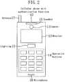
- FIG. 2is a diagram for showing the appearance of a cellular phone with an authentication function described as an example of an image capturing device to be used in practicing the personal authentication method of this embodiment
- FIG. 3is a diagram for showing the internal arrangement of the cellular phone with the authentication function of FIG. 2 . It is assumed in this embodiment that a user (a person to be authenticated) performs the iris authentication in outdoor light by using the cellular phone with the authentication function as shown in FIG. 2 .
- a camera 11 for capturing an iris image and lighting 12are additionally provided to a general cellular phone.
- This cellular phone 10includes, in addition to the camera 11 and the lighting 12, a monitor 13, operation buttons 14, a speaker 15, a microphone 16, an antenna 17 and the like.
- One or a plurality of near-infrared LEDsare used as the lighting 12. The lighting of the near-infrared light is used so as not to dazzle a user and so as to capture a dark brown iris pattern with high contrast.
- the camera 11is provided with a visible light cut filter so as to receive a near-infrared component alone. On the monitor 13 , an iris image to be captured and an authentication result are displayed.
- an iris imageis captured in light including a large quantity of near-infrared component, such as light from the sunlight and an incandescent lamp, there is no need to always provide the lighting, and when it is provided, there is no need to always light it.
- a large quantity of near-infrared componentsuch as light from the sunlight and an incandescent lamp
- a camera control unit 22, a lighting control unit 23 and a monitor control unit 24are connected to a main control unit 27 in authentication means 21.
- the camera control unit 22controls the camera 11 to capture an iris image, and captured iris images are stored in an image memory 25.
- An authentication processing unit 26performs authentication processing by using the iris images stored in the image memory 25.
- the lighting control unit 23controls the lighting 12 so as to light an iris region in synchronization with timing of capturing each image.
- the monitor control unit 24controls a display screen of the monitor 13.
- a userholds the cellular phone 10 with the authentication function shown in FIG. 2 , and captures, in the outdoor light, a plurality of (N) iris images in which positions of extraneous light reflection are respectively different (A1).
- the userholds the cellular phone 10 in a position away from his/her eye by a predetermined distance (of, for example, approximately 20 cm when the camera 11 has a single focus), and while confirming an iris image captured by the camera 11 and displayed on the monitor 13, adjusts the position of the eye so that the entire iris region can be included in the viewing field and be in focus.
- a camera buttonfor capturing allocated to one of the operation buttons 14. This operation is repeated N times so that the positions of the extraneous light reflection are different in the respective images.
- N frame imagescan be continuously captured by obtaining an image sequence.
- the extraneous lightis reflected over a wide region.
- a near-infrared component included in the sunlightwhich is an electromagnetic wave with a wide frequency band including UV, visible light, near-infrared light, far infrared light and the like
- has large strengthand hence, not only the near-infrared component of the direct sunlight but also near-infrared components reflected from a large number of objects irradiated with the sunlight enter the eye from various angles. (Since an eye ball has a shape close to a sphere, the reflection can be easily caused.)
- the position of the extraneous light reflectionis determined depending upon the positional relationship between the light source (including the reflecting object), the camera and the eye ball, and therefore, one of them is moved to change the position of the reflection.
- the light sourceis difficult to move, and hence, one or both of the camera and the eye ball are moved.
- FIG. 5shows four exemplified iris images captured with the positions of the camera and the face fixed and the direction of the eye ball (the direction of the sight line) alone changed.
- FIG. 6shows four exemplified iris images captured with the relative positional relationship between the camera and the eye ball fixed and the facing direction changed among the north, south, east and west.
- the eye ballis moved (namely, the direction of the sight line is changed)
- the position of the reflection with respect to the iris regionis changed.
- the shape of the reflectionis changed as the facing direction is changed.
- the device as shown in FIG. 2is used for instructing the user on the facing direction or guiding the direction of the sight line of the user.
- the facing directionis displayed on the monitor 13 with an arrow (in which case the monitor 13 and its control unit correspond to means for instructing the facing direction)
- the facing directionis instructed with a voice from the speaker 15 (in which case the speaker 15 and its control unit correspond to the means for instructing the facing direction)
- a specific imagesuch as the image of a character is displayed on the monitor 15 so as to move the image to a direction for guiding the sight line (in which case the monitor 13 and its control unit correspond to means for guiding the sight line).
- the devicecan provide a user-friendly interface.
- the plural iris images in which the positions of the extraneous light reflection are respectively differentcan be easily captured.
- the following processing A2 through A5are executed by the authentication processing unit 26.
- a method disclosed in National Publication of translated version No. 8-504979International Publication No. WO94/09446 , hereinafter referred to as the reference document 1 is employed.
- the iris authentication method of the reference document 1is performed roughly through the following steps:
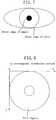
- FIG. 7is a diagram for showing the positions of the outer edge of an iris and the outer edge of a pupil
- FIG. 8is a diagram, expressed by using the xy rectangular coordinate system, of a region surrounded between the outer edge of the iris and the outer edge of the pupil cut out as the iris region. At this point, the influence of parallel movement of the iris region is absorbed.
- FIG. 9is a diagram of the iris region expressed by using the r ⁇ polar coordinate system with the center of the pupil set as the center of the coordinate (obtained through the conversion in step (2)).
- the actual outer edges of an iris and a pupilare not accurately circular, but if they are approximated to a circle, the center of the pupil and the center of the iris are not concentric (but eccentric). However, when a value in the r-direction is set to 0 on the outer edge of the pupil and to 1 on the outer edge of the iris, the eccentricity, a difference in the dilation of the pupil and the influence of expansion/reduction can be absorbed.
- FIG. 10is a diagram of the 8 ring-shaped analysis zones determined in step (3).
- FIGS. 11A through 11Care diagrams for showing generation of the iris code in step (4).
- a luminance signal as shown in FIG. 11Ais obtained after determining the analysis zones, the Gabor filter is applied to give a signal as shown in FIG. 11B and this signal is binarized as shown in FIG. 11C .
- the signalis actually two-dimensional, it is herein shown as a one-dimensional signal for simplification.
- FIG. 11Ashows an angular direction luminance signal obtained in one of the 8 ring-shaped zones.
- the Gabor filter of multi-scaleis actually applied, and there are a real part and an imaginary part even in a Gabor filter of single-scale.
- FIGS. 11B and 11Cshow the signals obtained by applying a real part of the Gabor filter of a given scale. The position of each bit in the iris code shown in FIG. 11C resulting from the binarization can be made to correspond to a given position in the iris image.
- the captured N iris imagesare subjected to feature extraction, so as to respectively generate N iris codes as iris data corresponding to features for the authentication (A2).
- the aforementioned steps (1) through (4)are performed on each of the N iris images in which the positions of the extraneous light reflection are respectively different, so as to generate the N iris codes.
- steps (1) through (3)are performed on each image, an iris code in which the influences of the parallel movement, the expansion/reduction, the difference in the dilation of the pupil and the eccentricity of the pupil are absorbed is generated with respect to each iris region of the plural iris images.
- the N iris codesare respectively compared with the registered iris code previously registered as registered iris data of the user, so as to obtain N comparison results (A3).
- corresponding bitsare compared between the two iris codes, so as to generate, as the "comparison result", a bit string showing match/mismatch between the compared bits. Since an XOR operation is used for comparing the bits, when they match, "0" is given as a bit value, and when they do not match, "1" is given as a bit value. Also; such a bit value expressing the match/mismatch is used as a "determination result".
- the above-described step (5)is performed.
- the iris code for authenticationis rotated in a previously determined range for matching, so that the minimum hamming distance can be obtained as the ultimate hamming distance.
- FIG. 12This processing is shown in FIG. 12 .
- FIG. 12for the sake of simplification, a real part of the Gabor filter of a given scale is applied for the analysis, and one of the 8 ring-shaped zones is shown.
- FIG. 13is a diagram for showing the result of the comparison between the registered iris code and the N iris codes for authentication.
- the iris codes 1 through N for authentication shown in FIG. 13have already been subjected to the rotation compensation matching so as to be shifted to positions for minimizing the hamming distances.
- the ith bit positions in the codesall correspond to the same position in the iris pattern.
- each iris code for authenticationis divided into M blocks, and a block having a hamming distance larger than a predetermined threshold value TH2 (of 0.30 in this embodiment) is shown as a black block.
- TH2of 0.30 in this embodiment
- the iris codes 1, 2 and N for authenticationrespectively have hamming distances of 0.31, 0.33 and 0.34.
- a hamming distanceis 0.5 when two codes are not correlated with each other at all.
- Hamming distances obtained between two different personsare distributed around 0.5, but a hamming distance is shifted to be slightly smaller when the rotation compensation matching is performed.
- a threshold value TH1 of the hamming distance for the authenticationis 0.30, these iris codes for authentication are all rejected when singly used.
- the hamming distances of the most blocksare not more than the threshold value TH2
- the hamming distance HD of the entire iris code for authenticationis larger than the threshold value TH1 because merely some blocks (the black blocks) have large hamming distances. It seems that these blocks have the large hamming distances HD because of the extraneous light reflection.
- a plurality of comparison resultsare synthesized and integrated to generate an ultimate comparison score (A4).
- A4an ultimate comparison score
- a “comparison score”means a scholar value representing the matching degree resulting from the comparison between two iris codes.
- a ratio in the number of mismatch bits to all compared bits, namely, the hamming distance,is used as the "comparison score".
- the comparison resultsmay be synthesized in each bit or in each block.
- FIG. 14is a flowchart of detailed procedures in the processing A4 performed when the comparison results are synthesized in each bit.
- comparison resultseach having a hamming distance not more than a predetermined threshold value TH3 (> TH1 ) are first selected from the N comparison results (A401).
- attentionis paid to the ith bit position (A402), and if any bit in the attended bit position of the selected comparison results matches with the corresponding one of the registered iris code, the ultimate determination result of that bit position is determined to match (A403).
- These procedures of steps A402 and A403are executed on all the bit positions (A404).
- the number of ultimately mismatch bitsis normalized with the total number of bits, so as to calculate a hamming distance as the ultimate comparison score (S405).
- step A401a comparison result having a hamming distance larger than the threshold value TH3 is excluded for the following steps because it is highly probably obtained from an iris image of a person who is not the registered person.
- merely comparison results each having a hamming distance larger than the threshold value TH1 for the authentication and smaller than the predetermined threshold value TH3are accepted for the following steps under interpretation that "the hamming distance exceeds the threshold value TH1 because there is extraneous light reflection in the iris image of the registered person".
- the increase of the false acceptance ratio (FAR)that is, a ratio of authenticating a person not to be authenticated by mistake, can be suppressed.
- FARfalse acceptance ratio
- comparison results each having a score not less than a predetermined valueare selected in step A401.
- the N comparison resultsmay be subjected to a majority decision in the match/mismatch, so that the major result can be regarded as the ultimate determination result of that bit position.
- the ultimate determination result of the attended bit positionmay be determined depending upon whether or not the ratio of matches in the N comparison results is larger than a predetermined threshold value.
- the ratio of matches in the N comparison resultsis obtained as a score of that bit position, so that an average of the scores of all the bit positions can be obtained as the ultimate comparison score.
- a weighted average of the N comparison resultsmay be used for obtaining the ultimate determination result of that bit position.
- An example of the specific methodis as follows: First, a weight w k (0 ⁇ w k ⁇ 1; wherein k is a comparison result number) that increases as the reliability of a comparison result is higher is prepared.
- the denominatoris a normalized term for making the sum of the weights w k to be 1.
- the common weight w kis used for all the bit positions of the kth comparison result.
- weightsmay be used for the respective bit positions as follows: First, a weight w k,i (0 ⁇ w k,i ⁇ 1; k is a comparison result number; and i is a bit position) that increases as the reliability of a comparison result is higher is prepared.
- the word "local"means being local on the iris image.
- a bit value r k,i with a small local hamming distanceis judged to have high reliability and hence is provided with a large weight.
- the denominatoris a normalized term for making the sum of the weights w k,i with respect to k to be 1.
- x k,imay be a luminance value (of a point or a local area) on the iris image corresponding to the ith bit of the kth comparison result.
- a bit corresponding to a portion with a large luminance valueis judged to highly probably have an unstable value due to the reflection and have low reliability, and hence is provided with a smaller weight.
- FIG. 15is a flowchart for showing detailed procedures in the processing A4 performed in synthesizing the comparison results in each block.
- comparison results each having a hamming distance not more than the predetermined threshold value TH3 (> TH1 )are first selected from the N comparison results (A411).
- the iris code for authentication obtained from each of the selected comparison resultsis divided into M blocks (A412).
- the block divisionis performed as follows: The iris image is previously divided, and when pixels corresponding to bits of the iris code belong to the same block in the iris image, these bits of the iris code are made to belong to the same block.
- the iris imageis divided, for example, concentrically and radially as shown in FIG. 16A or rectangularly as shown in FIG. 16B .
- comparison results of the blocks with the minimum hamming distancesare all integrated (A416).
- a comparison result of a blockis a bit string showing the match/mismatch of the corresponding bits belonging to the block between two iris codes. Then, the number of ultimately mismatch bits is normalized with the total number of bits, so as to calculate a hamming distance as the ultimate comparison score (A417).
- step A411the effect obtained in step A411 is the same as that obtained in step A401 of the synthesis in each bit.
- the authenticationis performed by using the ultimate comparison score (hamming distance) (A5).
- the hamming distanceis not more than the predetermined threshold value TH1
- the useris authenticated to accept, and otherwise, the user is rejected as another person.
- the ultimate authentication resultis displayed on the monitor 13 of the cellular phone 10 with the authentication function of FIG. 2 .
- step A417 in the synthesis in each block and the processing A5may be combined.
- all the hamming distances within the respective blocksare not more than the predetermined threshold value TH2 ( ⁇ TH1 ), the user is authenticated to accept, and otherwise, the user is rejected as another person.
- the image capturing deviceinstructs a user on the direction of the face or the sight line (eye ball), the device with good user interface can be provided.
- the ultimate comparison scoreis obtained by integrating a plurality of comparison results, the influence of the extraneous light reflection or the shadow of the eyelid or eyelashes on the authentication accuracy can be reduced.
- the comparison resultsare integrated in each block, it is possible to avoid accepting a person who is not the registered person to be authenticated. Also, since comparison results with hamming distances larger than the predetermined threshold value are not used, it is possible to avoid accepting a person who is not the registered person to be authenticated.
- FIG. 17shows the appearance of a cellular phone with the authentication function including a plurality of cameras usable as the image capturing device of the invention.
- the cellular phone shown in FIG. 17two. cameras 11a and 11b are provided in positions away from each other in the vertical direction.
- this cellular phoneis used, two iris images in which the positions of the extraneous light reflection are different can be captured at one time. Such an operation is performed once or repeated a plurality of times.
- a device including cameras in number larger than 2is used, a larger number of iris images in which the positions of the extraneous light reflection are respectively different can be captured through one operation.
- FIG. 18shows the appearance of a fixed type door phone with an iris authentication function to be installed at the entrance of a house or the like that is usable as the image capturing device of this invention.
- the door phone 30 of FIG. 18is provided with a plurality of guiding lamps 36a through 36h serving as means for guiding the direction of the sight line of a user.
- the guiding lampsare successively lighted one by one in a predetermined order, so that the user can turn his/her eye toward the lighted guiding lamp for capturing each iris image.
- targets for guiding the sight lineare thus provided on the image capturing device, a user can easily grasp in which direction he/she should turn his/her eye, and can be prevented from being largely troubled in moving the sight line.
- the deviceattains a user friendly interface.
- the image capturing devicemay instruct a user to change the position of the image capturing device itself including a camera.
- the image capturing deviceinstructs the user on the direction for moving his/her hand holding the image capturing device.
- the instructionmay be given by displaying a message or an arrow on the monitor 13 (in which case the monitor 13 and its control unit correspond to means for instructing on the direction for moving the hand), or the instruction may be given with a voice from the speaker 15 (in which case the speaker 15 and its control unit correspond to the means for instructing on the direction for moving the hand).
- the image capturing devicemay be provided with a camera variable in its position, so that the position of the camera can be changed automatically or manually by a user in capturing an iris image.
- a camera variable in its positionso that the position of the camera can be changed automatically or manually by a user in capturing an iris image.
- an iris imageis captured front ways with merely the eye ball moved, if the eye ball is largely moved, the iris is shot in an oblique direction, and hence, the outer edge of the iris (and the outer edge of the pupil) is in an elliptical shape in the resultant iris image.
- the distortion correctioncan be realized through linear transformation (matrix calculation).
- the image capturing devicemay be provided with a switch for turning on/off the lighting 12, so that the lighting 12 can be turned off when the authentication is performed in the outdoor light.
- the image capturing devicemay be provided with a near-infrared light intensity sensor so that the lighting 12 cannot be lighted in capturing iris images when the near-infrared light intensity of the outdoor light exceeds a predetermined threshold value.
- all the processing A1 through A5are performed on the terminal.
- the processing A1 for capturing a plurality of iris images alonemay be performed on the terminal, and the plural images are sent to a server via a network, so that the processing A2 through A5 can be performed on the server.
- the authentication resultis calculated on the server, and the calculation result is sent to the terminal via the network again, so as to display the authentication result on the monitor 13 of the terminal.
- the authenticationis performed after capturing N (a fixed number of) images in which the positions of the extraneous light reflection are respectively different.
- the aforementioned processingmay be performed after capturing each image so as to calculate the ultimate hamming distance, and when the hamming distance is not more than the predetermined threshold value, the authentication may be completed, and otherwise, the next image may be captured.
- the upper limit of the number of images to be capturedmay be set.
- the inventionprovides the countermeasure against the extraneous light reflection, and hence, if the extraneous light is not reflected, there is no need to capture a plurality of iris images. Furthermore, a system in which a plurality of images are always captured is troublesome for a user. Therefore, the following method may be employed: As shown in a flowchart of FIG. 25 , after capturing one iris image (D1), general authentication (by the method disclosed in the reference document 1) is performed (D2). At this point, the captured iris image is compared with registered iris data of a user previously registered, so as to obtain a comparison result.
- step D3When the authentication is successful, for example, when a hamming distance obtained in step D2 is not more than a predetermined threshold value, the processing is ended. Otherwise, for example, when the hamming distance exceeds the predetermined threshold value, the flow proceeds to step D4 (D3).
- step D4the comparison result obtained in step D2 is divided into a plurality of blocks, and a hamming distance is calculated as a comparison score with respect to each of the divided blocks. Then, the number M2 of blocks each having a hamming distance larger than a first threshold value is counted (D5). When the number M2 of blocks is smaller than a second threshold value, it is determined in step D6 that the user is highly probably the registered person and that the extraneous light reflection is caused in the image, and the processing of this embodiment is performed (D7). On the other hand, when the number M2 of blocks exceeds the second threshold value, the user is rejected as another person (D8) and the processing is ended. Specifically, processing for determining whether or not the extraneous light reflection is caused in the captured iris image is performed through steps D2 through D6.
- condition for performing the processing of this embodimentmay be set as follows:
- the iris authenticationis performed in the outdoor light on the basis of the switch setting of the lighting or the near-infrared light intensity. For example, as shown in FIG. 26 , the intensity of the near-infrared light in the environment for capturing an image is first measured (E1), and when the measured intensity is not less than a predetermined threshold value (YES in E2), the processing of this embodiment is performed (E3). On the other hand, when the measure intensity is lower than the predetermined threshold value (NO in E2), merely one iris image is captured (E4) and the authentication is performed in the conventional manner (E5).
- an area where the extraneous light reflection is presentis presumed in the same manner, so as to obtain the direction for moving the hand. Furthermore, on the basis of the position of an area where the extraneous light reflection is present, a distance for moving the hand is obtained, which may be also instructed.
- a plurality of iris codesare respectively compared with a registered iris code for generating a plurality of comparison results, and the plural comparison results are integrated to obtain an ultimate comparison score to be used for the authentication.
- a plurality of iris codesare integrated to generate an integrated iris code, and the integrated iris code is compared with a registered iris code for the authentication.
- FIG. 19is a flowchart of a personal authentication method utilizing iris authentication according to Embodiment 2 of the invention.
- N iris images in which the positions of the extraneous light reflection are respectively differentare first captured (B1), and the captured N iris images are subjected to the feature extraction so as to generate N iris codes (B2).
- the processing B1 and B2can be performed in the same manner as the processing A1 and A2 of Embodiment 1.
- FIG. 20is a flowchart for showing detailed procedures in the processing B3.
- an iris code ICjthat attains the minimum sum of the hamming distances from all the other (N-1) codes ICi (i ⁇ j) is selected (B302).
- a value of the kth bit (Oor1)is decided by majority, so as to determine the value of the kth bit of the integrated iris code (B303).
- the kth position of the iris code ICj used as the referenceis allowed to correspond to the kth position in the iris code ICi obtained after rotating it by the rotation compensation angle employed for calculating the hamming distance in step B301.
- the integrated iris codeis generated from the N iris codes. In this manner, when the number of bits affected by the extraneous light reflection in an arbitrary bit position of the iris code is smaller than N/2, an integrated iris code free from the influence of the extraneous light reflection can be generated.
- the integrated iris codeis compared with a registered iris code, so as to obtain a comparison result (B4), which is used for the authentication (B5).
- the processing B4 and B5can be performed in the same manner as in the method disclosed in the reference document 1, namely, steps (5) and (6) described in Embodiment 1.
- the iris code ICj used as the referenceis selected under a condition that the sum of the hamming distances from all the other (N-1) codes ICi (i ⁇ j) is the minimum.
- the N iris codesare compared with the registered iris code, so that an iris code with the smallest hamming distance can be selected to be used as the reference.
- a majority decisionis employed for the integration of the plural iris codes in this embodiment, but for example, a weighted average may be used instead.
- hamming distances between the N iris codes and the registered iris codemay be calculated so that merely iris codes with hamming distances not more than the predetermined threshold value TH3 can be used for generating the integrated iris code.
- Embodiment 2the iris codes obtained after the binarization as shown in FIG. 11C are integrated.
- the signals obtained by applying the Gabor filter as shown in FIG. 11Bmay be integrated so as to binarize the integrated signal. Now, this method will be described as a modification of Embodiment 2.
- FIG. 21is a flowchart of a personal authentication method utilizing iris authentication according to this modification.
- the same processing as those shown in FIG. 19are referred to with the same step numbers so as to omit the detailed description.
- the luminance levels of the N iris imagesare adjusted (B15).
- a lens diaphragm value or a gain value for the AGCis obtained from the camera, so as to adjust the luminance levels.
- the N iris imagesare subjected to the feature extraction, so as to generate N intermediate iris codes serving as iris data corresponding to the features to be used for the authentication (B21).
- the method disclosed in the reference document 1, namely, steps (1) through (3) described in Embodiment 1is performed, and furthermore, the 2-d Gabor filter is applied as in step (4) for carrying out multi-scale frequency analysis, and thus, a multivalued signal as shown in FIG. 11B is obtained. This multivalued signal is used as the intermediate iris code.
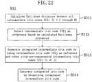
- FIG. 22is a flowchart for showing detailed procedures in the processing B31.
- a Euclidean distance between intermediate iris codes IC2i and IC2j obtained when they are shifted by x in the angular directionis represented by the following equation (1):
- the Euclidean distance ED ij in a position for minimizing the Euclidean distanceis represented by the following equation (2) using the equation (1):
- E D ijmin x E D ij x
- an intermediate iris code IC2j that attains, with the intermediate iris code IC2j used as the reference, the minimum sum of the Euclidean distances from all the other (N-1) intermediate codes IC2i (i ⁇ j)is selected (B312). Thereafter, between the selected intermediate iris code IC2j and the other intermediate codes IC2i (i ⁇ j), a median value of the kth signal values in the intermediate codes is obtained, so as to determine a value of the kth signal of the integrated intermediate iris code (B313).
- the kth position of the iris code IC2i used as the referenceis allowed to correspond to the kth position in the iris code IC2j obtained after rotating it by the rotation compensation angle employed for calculating the Euclidean distance in step B311.
- the integrated intermediate iris codeis generated from the N intermediate iris codes.
- a median valueis used for obtaining a Gabor filter output signal in which the influence of the extraneous light reflection is reduced.
- a weighted averagemay be used. (Although a simple average may be used, the use of a simple average is easily affected by an off value derived from the extraneous light reflection.)
- the integrated intermediate iris codeis binarized, so as to generate an integrated iris code (B314).
- the binarizationis performed in the same manner as in the generation of an iris code (shown in FIG. 11C ) from a general intermediate iris code (shown in FIG. 11B ).
- the integrated iris codeis compared with a registered iris code, so as to obtain a comparison result (B4), which is used for the authentication (B5).
- a plurality of comparison resultsare integrated in Embodiment 1, and a plurality of iris codes or intermediate iris codes are integrated in Embodiment 2.
- a plurality of iris imagesare integrated so as to generate an integrated iris image, an iris code is extracted from the integrated iris image, and the iris code is compared with a registered iris code for the authentication.
- FIG. 23is a flowchart of a personal authentication method utilizing iris authentication according to Embodiment 3 of the invention.
- N iris images in which the positions of the extraneous light reflection are respectively differentare first captured (C1), and the luminance levels of the N iris images are adjusted (C15).
- the processing C1 and C15can be executed in the same manner as the processing B1 and B15 of Embodiment 2.
- FIG. 24is a flowchart for showing detailed procedures in the processing C2.
- one of the N iris imagesis selected (C200).
- the outer edge of an iris and the outer edge of a pupilare determined (C201), and an iris region is converted from the xy rectangular coordinate system to the r ⁇ polar coordinate system (C202).
- the processing C201 and C202are executed by the method disclosed in the reference document 1.
- the processing C201 and C202are executed with respect to all the N iris images (C203).
- Euclidean distances between all the polar coordinate imagesare calculated (C204).
- the number of combinations of the imagesis N(N-1)/2.
- the equation (3)represents a Euclidean distance obtained when the image is shifted by x in the angular direction for absorbing the inclination of the face or the rotation of the eye ball itself.
- a polar coordinate image Ij that attains, with the polar coordinate image Ij used as the reference, the minimum sum of the Euclidean distances from all the other (N-1) polar coordinate images (i ⁇ j)is selected (C205). Thereafter, between the selected polar coordinate image Ij and the other polar coordinate images Ii (i ⁇ j), a median value of the luminance of a pixel (r, ⁇ ) is obtained, so as to determine the luminance of the pixel (r, ⁇ ) of an integrated polar coordinate image (C206).
- a coordinate resulting from the rotation correction for minimizing the Euclidean distance from the selected polar coordinate image Ijis used.
- a weighted averagemay be used instead of a median value. (Although a simple average can be used, the use of a simple average can be easily affected by an off value derived from the extraneous light reflection.)
- an iris codeis generated from the integrated iris image (C3), and the iris code is compared with a registered iris code so as to obtain a comparison result (C4). Thereafter, the comparison result is used for the authentication (C5).
- the processing C4 and C5can be performed by the method disclosed in the reference document 1.
- polar coordinate imagesare subjected to the rotation correction after adjusting the luminance level, and median values of the respective pixels are obtained to generate the synthesized polar coordinate image. Since a medium value is used, the influence of the reflection is reduced in the resultant polar coordinate image. In contrast, when an average is used, an off value derived from the reflection largely affects. Accordingly, the subsequent processing can be performed with the influence of the reflection reduced in this embodiment.
- Embodiment 2 and 3can also employ the procedure of step D7 of the flow of FIG. 25 or the procedure of step E3 of the flow of FIG. 26 .
- a plurality of iris images in which the positions of the extraneous light reflection are respectively differentare used, so that the authentication can be performed with the influence of the extraneous light reflection reduced. Accordingly, personal authentication with sufficiently high accuracy can be executed even in the outdoor light. Also, a plurality of iris images can be easily captured.
Landscapes
- Engineering & Computer Science (AREA)
- Theoretical Computer Science (AREA)
- Physics & Mathematics (AREA)
- General Physics & Mathematics (AREA)
- Computer Hardware Design (AREA)
- Computer Security & Cryptography (AREA)
- General Engineering & Computer Science (AREA)
- Health & Medical Sciences (AREA)
- Human Computer Interaction (AREA)
- General Health & Medical Sciences (AREA)
- Software Systems (AREA)
- Ophthalmology & Optometry (AREA)
- Multimedia (AREA)
- Biomedical Technology (AREA)
- Signal Processing (AREA)
- Computer Networks & Wireless Communication (AREA)
- Computing Systems (AREA)
- Spectroscopy & Molecular Physics (AREA)
- Measurement Of The Respiration, Hearing Ability, Form, And Blood Characteristics Of Living Organisms (AREA)
- Image Input (AREA)
- Collating Specific Patterns (AREA)
Description
- The present invention relates to a technique for personal authentication utilizing iris images, and more particularly, it relates to a technique to improve the accuracy in iris authentication in outdoor light such as sunlight.
- Recently, a technique for personal authentication utilizing iris images has started to be employed for management of entrances/exits of an important institution, authentication of a user of an ATM (Automated Teller Machine) of a bank or the like, authentication for logging in a PC and the like. In general, the iris authentication is performed through the following steps:
- 1. An iris image of a person is captured with a near-infrared illumination (ex. LED);
- 2. The iris image is analyzed to extract an iris code; and
- 3. The extracted iris code is compared with a previously registered iris code, and when a difference (distance) between these codes is not more than a threshold value, the person is authenticated.
- In this case, the near-infrared light is used for lighting because it is not perceptible for man and hence does not dazzle the person to be authenticated. In addition, most of the people on the earth have dark brown irises (although some people have blue or gray irises, they are globally minor), and the iris pattern of a dark brown iris is difficult to visually recognize in visible light but its image can be captured with high contrast in the near-infrared light. The iris pattern of a blue or gray iris can be also captured in the near-infrared light.
- As described above, the iris authentication has been started to be employed for the management of entrances/exits and the authentication of users of ATMs and for logging in PCs, and in most cases, the iris authentication is employed from a premise that it is performed indoor with a small quantity of near-infrared component of outdoor light. In the case where the iris authentication is performed in outdoor light, such as the sunlight, including a large quantity of near-infrared component, near-infrared light from the sun and the like and near-infrared light reflected by objects irradiated by the sun and the like are widely reflected in the eye. Also, in the case where the face is directly exposed to the sunlight, the shadow of the eyelid or eyelashes may be cast over the iris region. These factors can increase a false rejection rate (FRR). However, it is almost impossible that an obtained iris pattern accidentally resembles an iris pattern of another person due to such reflection and shadow of the eyelid or eyelashes. Therefore, there is little possibility of increase of a false acceptance rate (FAR).
- Mostly, the facilities for an ATM is located in the vicinity of the entrance of a building facing on a street. Methods for preventing the influence of the outdoor light are described in
patent documents patent document 1, reflection of the extraneous light is prevented as follows: First polarizing means is provided outside a lens of a camera for capturing an iris image, second polarizing means is provided between an iris authentication apparatus and the source of extraneous light (for example, on a window), and the first and second polarizing means have different polarization directions. Alternatively, according to thepatent document 2, the reflection of the extraneous light on an eye is prevented by providing, in a position from which the extraneous light enters the eye (for example, on a window), a non-visible light non-penetrating filter for reflecting or absorbing a non-visible light component lighting the eye out of frequency components of the extraneous light. - As alternative means for preventing the reflection, shielding means such as an eye cup is provided in front of a camera, and a person to be authenticated (hereinafter simply referred to as a user) looks into the shielding means for capturing an image of his/her iris.
- Furthermore, patent documents 3, 4, 5 and 6 describe methods for dealing with reflection of lighting means itself used for lighting an eye, which is not the outdoor light.
- According to the patent document 3, the head of a user is expected to move while a plurality of iris images are being captured, and the plural iris images are used for reducing the influence of the reflection. First, one image and a registered image are subjected to matching, and a consistent portion therebetween is added to a matching image. Thereafter, the other images are also subjected to the matching with the registered image, so as to successively add consistent portions to the matching image. The ultimate matching image thus formed is compared with the registered image for the authentication.
- In all the techniques disclosed in the patent documents 4, 5 and 6, a plurality of lighting means installed in different positions are used. Specifically, an eye is lighted with the plural lighting means at different timings, so as to capture a plurality of iris images respectively at the different lighting timings. A plurality of iris images (or features or comparison results) in which the positions of the reflection of the lighting means are respectively different are synthesized, so as to generate an iris image (or a feature or comparison result) that is free from the influence of the reflection.
- Patent document 1: Japanese Laid-Open Patent Publication No.
10-21392 - Patent document 2: Japanese Laid-Open Patent Publication No.
2000-185032 - Patent document 3: Japanese Laid-Open Patent Publication No.
9-212644 - Patent document 4: Japanese Laid-Open Patent Publication No.
10-162146 - Patent document 5: Japanese Laid-Open Patent Publication No.
11-203478 - Patent document 6: Japanese Laid-Open Patent Publication No.
2001-167252 - The aforementioned conventional techniques have, however, the following disadvantages:
The techniques disclosed in thepatent documents - Also, in the method in which the shielding means such as an eye cup is provided in front of a camera and a user looks into the shielding means for capturing the image of an iris, an advantage of the iris authentication, that is, contactless authentication, is spoiled. Therefore, this method is not preferable from the viewpoint of sanitation and user interface.
- Furthermore, the patent document 3 originally describes the countermeasure against not the reflection of the extraneous light but the reflection of the lighting means equipped on the authentication apparatus. Moreover, although the head of a user is expected to naturally move, when the head does not move, the influence of the reflection cannot be reduced and hence the effect cannot be attained. Furthermore, even if the head moves, the user stands in front of the apparatus for the authentication and hence dare not turn his/her eyes largely off the apparatus. Accordingly, there is little possibility that the position of the reflection is changed.
- Also, the methods described in the patent documents 4, 5 and 6 using plural lighting means are useful as the countermeasure against the reflection of the lighting means equipped on the authentication apparatus but are useless against the reflection in the outdoor light.
Reference EP 1 139 301 (A2 ) discloses an identity verification system for identifying persons with high accuracy, while avoiding direct contact with the device to prevent any negative psychological reaction from a user. The system includes: a camera unit and an image processing unit for obtaining object images of body parts (such as fingerprints and irides) by scanning, without physical contact; an image display unit for displaying layered images of the body part as scanned and a guide showing the body part in an optimal position; a control unit for extracting biometric characteristic data from object images and sending the data to a verification server after encrypting by an encryption unit; and a communications interface unit.- Reference
JP 2000-132686 (A part 13 is larger than the second prescribed value. - Reference
US 6,088,470 (A ) discloses a method for illuminating and imaging eyes uses multiple light sources producing multiple images of a subject each created under illumination by different illuminators. A composite image of the subject is formed by selecting pixels based upon their gray scale values or using pyramid image processing. A composite image can be created which is free of bright spots commonly caused by reflection of illumination from eyeglasses that may be worn by a subject or for which is free of dark shadows or which is free of both bright spots and dark shadows. - An object of the invention is, in personal authentication utilizing an iris image, preventing an authentication accuracy from lowering even when extraneous light is reflected on an iris.
- This is achieved by the features of the independent claims. Preferred embodiments are the subject matter of dependent claims.
FIG.1 is a flowchart of a personal authentication method utilizing an iris image according toEmbodiment 1 of the invention;FIG.2 is a diagram of a cellular phone with an authentication function described as an example of an image capturing device of this invention;FIG.3 is a schematic diagram of the internal arrangement of the cellular phone ofFIG.2 ;FIG.4 is a diagram of an iris image in which extraneous light is reflected in an iris region;FIG.5 is a diagram of iris images captured with the direction of the eye ball (the direction of the sight line) respectively changed;FIG.6 is a diagram of iris images captured with the facing direction respectively changed;FIG:7 is a diagram for showing the outer edge of a pupil and the outer edge of an iris;FIG.8 is a diagram of an iris image expressed by using an xy rectangular coordinate system;FIG.9 is a diagram of an iris image expressed by using an rθ polar coordinate system;FIG.10 is a diagram for showing analysis zones obtained by dividing an iris into eight ring-shaped portions;FIGS.11A, 11B and11C are diagrams for showing a method for generating an iris code;FIG.12 is a diagram for showing a method for comparing two iris codes with rotation compensation;FIG.13 is a diagram for showing a result of comparison of N iris codes with a registered iris code;FIG.14 is a flowchart of processing A4 ofFIG. 1 performed in synthesis in each bit;FIG.15 is a flowchart of the processing A4 ofFIG. 1 performed in synthesis in each block;FIGS.16A and16B are diagrams for showing a method for dividing an iris region of an iris image into blocks;FIG.17 is an outline diagram of a cellular phone with an authentication function equipped with a plurality of cameras;FIG.18 is an outline diagram of a door phone with an authentication function equipped with guiding lamps;FIG.19 is a flowchart of a personal authentication method utilizing iris authentication according toEmbodiment 2 of the invention;FIG.20 is a flowchart for showing detailed procedures in processing B3 ofFIG. 19 ;FIG.21 is a flowchart of a personal authentication method utilizing iris authentication according to a modification ofEmbodiment 2 of the invention;FIG.22 is a flowchart for showing detailed procedures in processing B31 ofFIG. 21 ;FIG.23 is a flowchart of a personal authentication method utilizing iris authentication according to Embodiment 3 of the invention;FIG.24 is a flowchart for showing detailed procedures in processing C2 ofFIG. 23 ;FIG.25 is a flowchart of a personal authentication method including processing for determining, at an image level, whether or not extraneous light is reflected; andFIG.26 is a flowchart of a personal authentication method including processing for determining whether or not the authentication is performed in the outdoor light.- Preferred embodiments of the invention will now be described with reference to the accompanying drawings.
- Herein, "extraneous light" means light other than that of lighting used for capturing iris images and included in an iris authentication apparatus or an image capturing device. Also, "reflection" means a luminance pattern formed due to spatially uneven "extraneous light" in an iris region of a captured iris image.
FIG.1 is a flowchart of a personal authentication method utilizing iris authentication according toEmbodiment 1 of the invention.FIG.2 is a diagram for showing the appearance of a cellular phone with an authentication function described as an example of an image capturing device to be used in practicing the personal authentication method of this embodiment, andFIG.3 is a diagram for showing the internal arrangement of the cellular phone with the authentication function ofFIG.2 . It is assumed in this embodiment that a user (a person to be authenticated) performs the iris authentication in outdoor light by using the cellular phone with the authentication function as shown inFIG. 2 .- In the
cellular phone 10 with the authentication function ofFIG.2 , acamera 11 for capturing an iris image andlighting 12 are additionally provided to a general cellular phone. Thiscellular phone 10 includes, in addition to thecamera 11 and thelighting 12, amonitor 13,operation buttons 14, aspeaker 15, amicrophone 16, anantenna 17 and the like. One or a plurality of near-infrared LEDs are used as thelighting 12. The lighting of the near-infrared light is used so as not to dazzle a user and so as to capture a dark brown iris pattern with high contrast. Thecamera 11 is provided with a visible light cut filter so as to receive a near-infrared component alone. On themonitor 13, an iris image to be captured and an authentication result are displayed. In the case where an iris image is captured in light including a large quantity of near-infrared component, such as light from the sunlight and an incandescent lamp, there is no need to always provide the lighting, and when it is provided, there is no need to always light it. - Also, in the internal arrangement shown in
FIG.3 , acamera control unit 22, alighting control unit 23 and amonitor control unit 24 are connected to amain control unit 27 in authentication means21. Thecamera control unit 22 controls thecamera 11 to capture an iris image, and captured iris images are stored in animage memory 25. Anauthentication processing unit 26 performs authentication processing by using the iris images stored in theimage memory 25. Thelighting control unit 23 controls thelighting 12 so as to light an iris region in synchronization with timing of capturing each image. Themonitor control unit 24 controls a display screen of themonitor 13. - Now, processing performed in the personal authentication method of this embodiment will be described in accordance with the flow shown in
FIG.1 . - First, a user holds the
cellular phone 10 with the authentication function shown inFIG.2 , and captures, in the outdoor light, a plurality of (N) iris images in which positions of extraneous light reflection are respectively different (A1). In capturing the images, the user holds thecellular phone 10 in a position away from his/her eye by a predetermined distance (of, for example, approximately 20 cm when thecamera 11 has a single focus), and while confirming an iris image captured by thecamera 11 and displayed on themonitor 13, adjusts the position of the eye so that the entire iris region can be included in the viewing field and be in focus. Thereafter, he/she presses a camera button for capturing allocated to one of theoperation buttons 14. This operation is repeated N times so that the positions of the extraneous light reflection are different in the respective images. Alternatively, after pressing a camera start button once, N frame images can be continuously captured by obtaining an image sequence. - At this point, the phenomenon of extraneous light reflection will be described in detail.
- As shown in
FIG.4 , in an iris image captured in the outdoor light, the extraneous light is reflected over a wide region. This is because a near-infrared component included in the sunlight (which is an electromagnetic wave with a wide frequency band including UV, visible light, near-infrared light, far infrared light and the like) has large strength, and hence, not only the near-infrared component of the direct sunlight but also near-infrared components reflected from a large number of objects irradiated with the sunlight enter the eye from various angles. (Since an eye ball has a shape close to a sphere, the reflection can be easily caused.) - The position of the extraneous light reflection is determined depending upon the positional relationship between the light source (including the reflecting object), the camera and the eye ball, and therefore, one of them is moved to change the position of the reflection. Among them, the light source is difficult to move, and hence, one or both of the camera and the eye ball are moved.
FIG. 5 shows four exemplified iris images captured with the positions of the camera and the face fixed and the direction of the eye ball (the direction of the sight line) alone changed. Also,FIG. 6 shows four exemplified iris images captured with the relative positional relationship between the camera and the eye ball fixed and the facing direction changed among the north, south, east and west. As is understood fromFIG. 5 , when the eye ball is moved (namely, the direction of the sight line is changed), the position of the reflection with respect to the iris region is changed. Also, as is understood fromFIG.6 , the shape of the reflection is changed as the facing direction is changed.- In this embodiment, in order to capture a plurality of iris images in which the positions of the extraneous light reflection are respectively different, the device as shown in
FIG.2 is used for instructing the user on the facing direction or guiding the direction of the sight line of the user. For example, the facing direction is displayed on themonitor 13 with an arrow (in which case themonitor 13 and its control unit correspond to means for instructing the facing direction), the facing direction is instructed with a voice from the speaker15 (in which case thespeaker 15 and its control unit correspond to the means for instructing the facing direction), or a specific image such as the image of a character is displayed on themonitor 15 so as to move the image to a direction for guiding the sight line (in which case themonitor 13 and its control unit correspond to means for guiding the sight line). In this manner, the user can easily grasp without being confused in which direction he/she should turn his/her face or gaze in capturing images, and thus, the device can provide a user-friendly interface. Thus, the plural iris images in which the positions of the extraneous light reflection are respectively different can be easily captured. - The following processing A2 through A5 are executed by the
authentication processing unit 26. Herein, a method disclosed in National Publication of translated version No. 8-504979 (International Publication No.WO94/09446 reference document 1 is performed roughly through the following steps: - (1) The outer edge of an iris (the boundary between an iris and a sclera) and the outer edge of a pupil (the boundary between a pupil and the iris) are determined so as to cut an iris region out.
- (2) The cut iris region is converted from an xy rectangular coordinate system to an rθ polar coordinate system.
- (3) Analysis zones are determined (by dividing the iris region into 8 ring-shaped zones in the radial direction).
- (4) A 2-d Gabor filter of multi-scale is applied, and a signal output from the Gabor filter is binarized to obtain an iris code.
- (5) A registered iris code previously registered is compared with the iris code obtained in the authentication (through exclusive OR), so as to calculate a hamming distance between the two codes.
- (6) When the hamming distance is not more than a threshold value, the user is authenticated to accept, and otherwise, the user is rejected as another person.
FIG. 7 is a diagram for showing the positions of the outer edge of an iris and the outer edge of a pupil, andFIG.8 is a diagram, expressed by using the xy rectangular coordinate system, of a region surrounded between the outer edge of the iris and the outer edge of the pupil cut out as the iris region. At this point, the influence of parallel movement of the iris region is absorbed. Also,FIG. 9 is a diagram of the iris region expressed by using the rθ polar coordinate system with the center of the pupil set as the center of the coordinate (obtained through the conversion in step (2)). The actual outer edges of an iris and a pupil are not accurately circular, but if they are approximated to a circle, the center of the pupil and the center of the iris are not concentric (but eccentric). However, when a value in the r-direction is set to 0 on the outer edge of the pupil and to 1 on the outer edge of the iris, the eccentricity, a difference in the dilation of the pupil and the influence of expansion/reduction can be absorbed.FIG. 10 is a diagram of the 8 ring-shaped analysis zones determined in step (3).FIGS. 11A through 11C are diagrams for showing generation of the iris code in step (4). A luminance signal as shown inFIG.11A is obtained after determining the analysis zones, the Gabor filter is applied to give a signal as shown inFIG.11B and this signal is binarized as shown inFIG.11C . Although the signal is actually two-dimensional, it is herein shown as a one-dimensional signal for simplification.FIG.11A shows an angular direction luminance signal obtained in one of the 8 ring-shaped zones. The Gabor filter of multi-scale is actually applied, and there are a real part and an imaginary part even in a Gabor filter of single-scale.FIGS.11B and11C show the signals obtained by applying a real part of the Gabor filter of a given scale. The position of each bit in the iris code shown inFIG. 11C resulting from the binarization can be made to correspond to a given position in the iris image.- First, the captured N iris images are subjected to feature extraction, so as to respectively generate N iris codes as iris data corresponding to features for the authentication (A2). In the processing A2, the aforementioned steps (1) through (4) are performed on each of the N iris images in which the positions of the extraneous light reflection are respectively different, so as to generate the N iris codes. At this point, when steps (1) through (3) are performed on each image, an iris code in which the influences of the parallel movement, the expansion/reduction, the difference in the dilation of the pupil and the eccentricity of the pupil are absorbed is generated with respect to each iris region of the plural iris images.
- Next, the N iris codes are respectively compared with the registered iris code previously registered as registered iris data of the user, so as to obtain N comparison results (A3). In each embodiment of this invention, corresponding bits are compared between the two iris codes, so as to generate, as the "comparison result", a bit string showing match/mismatch between the compared bits. Since an XOR operation is used for comparing the bits, when they match, "0" is given as a bit value, and when they do not match, "1" is given as a bit value. Also; such a bit value expressing the match/mismatch is used as a "determination result".
- In the processing A3, the above-described step (5) is performed. At this point, there may be a shift in the angular direction derived from the inclination of the face or the rotation of the eye ball between the registered iris code and the iris code for authentication. In order to compensate this shift, the iris code for authentication is rotated in a previously determined range for matching, so that the minimum hamming distance can be obtained as the ultimate hamming distance. This processing is shown in
FIG. 12 . InFIG. 12 , for the sake of simplification, a real part of the Gabor filter of a given scale is applied for the analysis, and one of the 8 ring-shaped zones is shown. FIG. 13 is a diagram for showing the result of the comparison between the registered iris code and the N iris codes for authentication. Theiris codes 1 through N for authentication shown inFIG. 13 have already been subjected to the rotation compensation matching so as to be shifted to positions for minimizing the hamming distances. Specifically, the ith bit positions in the codes all correspond to the same position in the iris pattern. Also, inFIG. 13 , each iris code for authentication is divided into M blocks, and a block having a hamming distance larger than a predetermined threshold value TH2 (of 0.30 in this embodiment) is shown as a black block.- According to the comparison result shown in
FIG. 13 , theiris codes - However, as shown in
FIG.13 , although the hamming distances of the most blocks are not more than the threshold valueTH2, the hamming distanceHD of the entire iris code for authentication is larger than the threshold valueTH1 because merely some blocks (the black blocks) have large hamming distances. It seems that these blocks have the large hamming distancesHD because of the extraneous light reflection. - Therefore, in this embodiment, a plurality of comparison results are synthesized and integrated to generate an ultimate comparison score (A4). Thus, in the case where the positions of the extraneous light reflection are respectively different in the plural iris images, the influence of the extraneous light reflection on the accuracy in the personal authentication can be eliminated. Herein, a "comparison score" means a scholar value representing the matching degree resulting from the comparison between two iris codes. In each embodiment of the invention, a ratio in the number of mismatch bits to all compared bits, namely, the hamming distance, is used as the "comparison score".
- For the integration of the comparison results, the comparison results may be synthesized in each bit or in each block.
FIG.14 is a flowchart of detailed procedures in the processing A4 performed when the comparison results are synthesized in each bit. InFIG.14 , comparison results each having a hamming distance not more than a predetermined threshold valueTH3 (>TH1) are first selected from the N comparison results (A401). Next, attention is paid to the ith bit position (A402), and if any bit in the attended bit position of the selected comparison results matches with the corresponding one of the registered iris code, the ultimate determination result of that bit position is determined to match (A403). These procedures of steps A402 and A403 are executed on all the bit positions (A404). The number of ultimately mismatch bits is normalized with the total number of bits, so as to calculate a hamming distance as the ultimate comparison score (S405).- At this point, in the case where a person who is not the registered person captures his/her N (which is a large number) iris images, the probability that any one of the N iris codes matches with the registered iris code in a given bit position is closer to "1" (because the probability of match/mismatch is 0.5 when there is no comparison between two codes). This also applies to the case where a plurality of persons who are not the registered person capture N iris images by turn. Therefore, if all the comparison results obtained from the plural iris images are used for the authentication, the probability that a person who is not the registered person is authenticated by mistake is increased.
- Accordingly, in step A401, a comparison result having a hamming distance larger than the threshold value TH3 is excluded for the following steps because it is highly probably obtained from an iris image of a person who is not the registered person. Specifically, merely comparison results each having a hamming distance larger than the threshold value TH1 for the authentication and smaller than the predetermined threshold value TH3 are accepted for the following steps under interpretation that "the hamming distance exceeds the threshold value TH1 because there is extraneous light reflection in the iris image of the registered person". In this manner, the increase of the false acceptance ratio (FAR), that is, a ratio of authenticating a person not to be authenticated by mistake, can be suppressed. In the case where an index that has a large value when there is high comparison and has a small value when there is low comparison is used instead of the hamming distance, comparison results each having a score not less than a predetermined value are selected in step A401.
- Also, in step S403, for example, with respect to the attended bit position, the N comparison results may be subjected to a majority decision in the match/mismatch, so that the major result can be regarded as the ultimate determination result of that bit position. Alternatively, the ultimate determination result of the attended bit position may be determined depending upon whether or not the ratio of matches in the N comparison results is larger than a predetermined threshold value. Further alternatively, with respect to the attended bit position, the ratio of matches in the N comparison results is obtained as a score of that bit position, so that an average of the scores of all the bit positions can be obtained as the ultimate comparison score.
- Furthermore, with respect to the attended bit position, a weighted average of the N comparison results may be used for obtaining the ultimate determination result of that bit position. An example of the specific method is as follows:
First, a weight wk (0≦ wk ≦ 1; wherein k is a comparison result number) that increases as the reliability of a comparison result is higher is prepared. For example, the weight is defined by the following equation (5):
- Then, a value ri of the ith bit of a synthesized comparison result is determined by using the following equation (6):

- Alternatively, different weights may be used for the respective bit positions as follows:
First, a weightwk,i (0 ≦ wk,i ≦ 1; k is a comparison result number; and i is a bit position) that increases as the reliability of a comparison result is higher is prepared. For example, the weight is defined by using the following equation (7):
- Then, a valueri of the ith bit of a synthesized comparison result is determined by using the following equation (8):

- Also, in the equation (7),xk,i may be a luminance value (of a point or a local area) on the iris image corresponding to the ith bit of the kth comparison result. In other words, a bit corresponding to a portion with a large luminance value is judged to highly probably have an unstable value due to the reflection and have low reliability, and hence is provided with a smaller weight.
- Needless to say, another weight apart from those described above may be used as far as it has a larger value as the reliability of the corresponding bit is higher.
FIG.15 is a flowchart for showing detailed procedures in the processing A4 performed in synthesizing the comparison results in each block. InFIG:15 , comparison results each having a hamming distance not more than the predetermined threshold valueTH3 (>TH1) are first selected from the N comparison results (A411). Next, the iris code for authentication obtained from each of the selected comparison results is divided into M blocks (A412). The block division is performed as follows: The iris image is previously divided, and when pixels corresponding to bits of the iris code belong to the same block in the iris image, these bits of the iris code are made to belong to the same block. The iris image is divided, for example, concentrically and radially as shown inFIG.16A or rectangularly as shown inFIG.16B .- Next, attention is paid to the ith block (A413), and a block with the minimum hamming distance is selected from the attended blocks of the respective iris codes (A414). These procedures of steps A413 and A414 are executed on all the blocks (A415).
- Thereafter, comparison results of the blocks with the minimum hamming distances are all integrated (A416). A comparison result of a block is a bit string showing the match/mismatch of the corresponding bits belonging to the block between two iris codes. Then, the number of ultimately mismatch bits is normalized with the total number of bits, so as to calculate a hamming distance as the ultimate comparison score (A417).
- In this synthesis in each block, the effect obtained in step A411 is the same as that obtained in step A401 of the synthesis in each bit.
- Referring to
FIG.1 again, the authentication is performed by using the ultimate comparison score (hamming distance) (A5). When the hamming distance is not more than the predetermined threshold valueTH1, the user is authenticated to accept, and otherwise, the user is rejected as another person. Then, the ultimate authentication result is displayed on themonitor 13 of thecellular phone 10 with the authentication function ofFIG.2 . - The procedure in step A417 in the synthesis in each block and the processing A5 may be combined. In this case, in the comparison result integrated in step A416, all the hamming distances within the respective blocks are not more than the predetermined threshold valueTH2 ( ≧TH1), the user is authenticated to accept, and otherwise, the user is rejected as another person.
- As described so far, since the images are captured with the position of the face, the eye ball or the camera moved in this embodiment, a plurality of iris images in which the positions of the extraneous light reflection are respectively different can be captured. Since the image capturing device instructs a user on the direction of the face or the sight line (eye ball), the device with good user interface can be provided.
- Furthermore, since the ultimate comparison score is obtained by integrating a plurality of comparison results, the influence of the extraneous light reflection or the shadow of the eyelid or eyelashes on the authentication accuracy can be reduced. Moreover, when the comparison results are integrated in each block, it is possible to avoid accepting a person who is not the registered person to be authenticated. Also, since comparison results with hamming distances larger than the predetermined threshold value are not used, it is possible to avoid accepting a person who is not the registered person to be authenticated.
- In addition, as a method for capturing a plurality of iris images in which the positions of the extraneous light reflection are respectively different, an image capturing device including a plurality of cameras is used for capturing images of an iris simultaneously or at different timing from a plurality of angles.
FIG. 17 shows the appearance of a cellular phone with the authentication function including a plurality of cameras usable as the image capturing device of the invention. In the cellular phone shown inFIG.17 , two.cameras FIG.18 shows the appearance of a fixed type door phone with an iris authentication function to be installed at the entrance of a house or the like that is usable as the image capturing device of this invention. Thedoor phone 30 ofFIG.18 is provided with a plurality of guidinglamps 36a through36h serving as means for guiding the direction of the sight line of a user. In capturing iris images, the guiding lamps are successively lighted one by one in a predetermined order, so that the user can turn his/her eye toward the lighted guiding lamp for capturing each iris image. When targets for guiding the sight line are thus provided on the image capturing device, a user can easily grasp in which direction he/she should turn his/her eye, and can be prevented from being largely troubled in moving the sight line. Thus, the device attains a user friendly interface.- Furthermore, the image capturing device may instruct a user to change the position of the image capturing device itself including a camera. In the case where a user uses, as the image capturing device, for example, the
cellular phone 10 with the authentication function shown inFIG.2 , the image capturing device instructs the user on the direction for moving his/her hand holding the image capturing device. In this case, the instruction may be given by displaying a message or an arrow on the monitor13 (in which case themonitor 13 and its control unit correspond to means for instructing on the direction for moving the hand), or the instruction may be given with a voice from the speaker15 (in which case thespeaker 15 and its control unit correspond to the means for instructing on the direction for moving the hand). - Furthermore, the image capturing device may be provided with a camera variable in its position, so that the position of the camera can be changed automatically or manually by a user in capturing an iris image. Thus, with the image capturing device at the ready merely once, iris images can be captured from different angles owing to the movement of the camera itself. Accordingly, a plurality of iris images can be easily captured.
- In the case where an iris image is captured front ways with merely the eye ball moved, if the eye ball is largely moved, the iris is shot in an oblique direction, and hence, the outer edge of the iris (and the outer edge of the pupil) is in an elliptical shape in the resultant iris image. In such a case, it is necessary to correct distortion in the input image so as to convert it into an iris image taken front ways before performing the subsequent processing. The distortion correction can be realized through linear transformation (matrix calculation).
- This embodiment is particularly useful in the authentication performed in the outdoor light, and the intensity of the near-infrared light of the outdoor light is much higher than the power of the
lighting 12, and hence, the effect of thelighting 12 is minimal. Therefore, the image capturing device may be provided with a switch for turning on/off thelighting 12, so that thelighting 12 can be turned off when the authentication is performed in the outdoor light. Alternatively, the image capturing device may be provided with a near-infrared light intensity sensor so that thelighting 12 cannot be lighted in capturing iris images when the near-infrared light intensity of the outdoor light exceeds a predetermined threshold value. - In this embodiment, all the processing A1 through A5 are performed on the terminal. Instead, the processing A1 for capturing a plurality of iris images alone may be performed on the terminal, and the plural images are sent to a server via a network, so that the processing A2 through A5 can be performed on the server. In this case, the authentication result is calculated on the server, and the calculation result is sent to the terminal via the network again, so as to display the authentication result on the
monitor 13 of the terminal. - In this embodiment, the authentication is performed after capturing N (a fixed number of) images in which the positions of the extraneous light reflection are respectively different. Instead, the aforementioned processing may be performed after capturing each image so as to calculate the ultimate hamming distance, and when the hamming distance is not more than the predetermined threshold value, the authentication may be completed, and otherwise, the next image may be captured. In this case, the upper limit of the number of images to be captured may be set.
- Also, the invention provides the countermeasure against the extraneous light reflection, and hence, if the extraneous light is not reflected, there is no need to capture a plurality of iris images. Furthermore, a system in which a plurality of images are always captured is troublesome for a user. Therefore, the following method may be employed:
As shown in a flowchart ofFIG. 25 , after capturing one iris image (D1), general authentication (by the method disclosed in the reference document 1) is performed (D2). At this point, the captured iris image is compared with registered iris data of a user previously registered, so as to obtain a comparison result. When the authentication is successful, for example, when a hamming distance obtained in step D2 is not more than a predetermined threshold value, the processing is ended. Otherwise, for example, when the hamming distance exceeds the predetermined threshold value, the flow proceeds to step D4 (D3). - In step D4, the comparison result obtained in step D2 is divided into a plurality of blocks, and a hamming distance is calculated as a comparison score with respect to each of the divided blocks. Then, the numberM2 of blocks each having a hamming distance larger than a first threshold value is counted (D5). When the numberM2 of blocks is smaller than a second threshold value, it is determined in step D6 that the user is highly probably the registered person and that the extraneous light reflection is caused in the image, and the processing of this embodiment is performed (D7). On the other hand, when the numberM2 of blocks exceeds the second threshold value, the user is rejected as another person (D8) and the processing is ended. Specifically, processing for determining whether or not the extraneous light reflection is caused in the captured iris image is performed through steps D2 through D6.
- Similarly, conditions for performing the processing of this embodiment may be set as follows:
- In the case where a pixel with luminance not less than a predetermined first threshold value is included in an iris image in number larger than a predetermined second threshold value; and
- with a given first threshold value calculated on the basis of average luminance of an iris image, in the case where a pixel with luminance not less than the threshold value is included in the iris image in number larger than a predetermined second threshold value. Under these conditions, it is judged whether or not the reflection is caused in the iris image at an image level on the basis of the iris image.
- Alternatively, the condition for performing the processing of this embodiment may be set as follows:
- In the case where the lighting of the image capturing device is turned off; or
- with a near-infrared light intensity sensor provided on the image capturing device, in the case where the near-infrared light intensity in the outdoor light obtained with the lighting turned off exceeds a predetermined threshold value.
- Under this condition, it is judged whether or not the iris authentication is performed in the outdoor light on the basis of the switch setting of the lighting or the near-infrared light intensity. For example, as shown in
FIG.26 , the intensity of the near-infrared light in the environment for capturing an image is first measured (E1), and when the measured intensity is not less than a predetermined threshold value (YES in E2), the processing of this embodiment is performed (E3). On the other hand, when the measure intensity is lower than the predetermined threshold value (NO in E2), merely one iris image is captured (E4) and the authentication is performed in the conventional manner (E5). - In the case where a plurality of images are captured with the eye ball moved, without instructing the direction for moving the eye ball at random, a direction for eliminating the reflection from an area where it is present in a previously captured image can be calculated for instruction An area where the extraneous light reflection is present can be presumed as an area corresponding to a block with a large hamming distance, that is, the feature of each divided block. Therefore, when an area where the extraneous light reflection is present can be presumed, it is easy to calculate in which direction the eye ball should be moved. Also, in the case where the iris authentication is performed with the image capturing device held with a hand as described above, an area where the extraneous light reflection is present is presumed in the same manner, so as to obtain the direction for moving the hand. Furthermore, on the basis of the position of an area where the extraneous light reflection is present, a distance for moving the hand is obtained, which may be also instructed.
- In
Embodiment 1, a plurality of iris codes are respectively compared with a registered iris code for generating a plurality of comparison results, and the plural comparison results are integrated to obtain an ultimate comparison score to be used for the authentication. In contrast, in this embodiment, a plurality of iris codes are integrated to generate an integrated iris code, and the integrated iris code is compared with a registered iris code for the authentication. FIG.19 is a flowchart of a personal authentication method utilizing iris authentication according toEmbodiment 2 of the invention. InFIG.19 , N iris images in which the positions of the extraneous light reflection are respectively different are first captured (B1), and the captured N iris images are subjected to the feature extraction so as to generate N iris codes (B2). The processing B1 and B2 can be performed in the same manner as the processing A1 and A2 ofEmbodiment 1.- Next, the N iris codes are integrated so as to generate an integrated iris code (B3).
FIG. 20 is a flowchart for showing detailed procedures in the processing B3. - First, with respect to the N iris codesICi (i = 1 through N), hamming distances from all the codes are calculated (B301). The number of combinations of the codes is N(N-1)/2. At this point, the rotation compensation matching is performed on the iris codes as shown in
FIG.12 . - Then, an iris codeICj that attains the minimum sum of the hamming distances from all the other (N-1) codesICi (i ≠ j) is selected (B302). Between the selected iris codeICj and the other codesICi (i ≠ j), a value of the kth bit (Oor1) is decided by majority, so as to determine the value of the kth bit of the integrated iris code (B303). At this point, the kth position of the iris codeICj used as the reference is allowed to correspond to the kth position in the iris codeICi obtained after rotating it by the rotation compensation angle employed for calculating the hamming distance in step B301.
- Through this processing B3, the integrated iris code is generated from the N iris codes. In this manner, when the number of bits affected by the extraneous light reflection in an arbitrary bit position of the iris code is smaller than N/2, an integrated iris code free from the influence of the extraneous light reflection can be generated.
- Then, the integrated iris code is compared with a registered iris code, so as to obtain a comparison result (B4), which is used for the authentication (B5). The processing B4 and B5 can be performed in the same manner as in the method disclosed in the
reference document 1, namely, steps (5) and (6) described inEmbodiment 1. - In the above description, the iris codeICj used as the reference is selected under a condition that the sum of the hamming distances from all the other (N-1) codesICi (i ≠ j) is the minimum. Instead, for example, the N iris codes are compared with the registered iris code, so that an iris code with the smallest hamming distance can be selected to be used as the reference.
- Also, a majority decision is employed for the integration of the plural iris codes in this embodiment, but for example, a weighted average may be used instead.
- Furthermore, in the same manner as in
Embodiment 1, hamming distances between the N iris codes and the registered iris code may be calculated so that merely iris codes with hamming distances not more than the predetermined threshold valueTH3 can be used for generating the integrated iris code. - In the method described in
Embodiment 2, the iris codes obtained after the binarization as shown inFIG.11C are integrated. In contrast, the signals obtained by applying the Gabor filter as shown inFIG.11B may be integrated so as to binarize the integrated signal. Now, this method will be described as a modification ofEmbodiment 2. FIG.21 is a flowchart of a personal authentication method utilizing iris authentication according to this modification. InFIG.21 , the same processing as those shown inFIG.19 are referred to with the same step numbers so as to omit the detailed description.- After capturing N iris images in which the positions of the extraneous light reflection are respectively different (B1), the luminance levels of the N iris images are adjusted (B15). In the case where iris images are captured with a user facing in different directions, there is a possibility that the luminance levels of the N iris images are different due to lens diaphragm control or AGC (auto gain control) of the camera itself. In this case, a lens diaphragm value or a gain value for the AGC is obtained from the camera, so as to adjust the luminance levels.
- Then, the N iris images are subjected to the feature extraction, so as to generate N intermediate iris codes serving as iris data corresponding to the features to be used for the authentication (B21). In this modification, the method disclosed in the
reference document 1, namely, steps (1) through (3) described inEmbodiment 1, is performed, and furthermore, the 2-d Gabor filter is applied as in step (4) for carrying out multi-scale frequency analysis, and thus, a multivalued signal as shown inFIG. 11B is obtained. This multivalued signal is used as the intermediate iris code. - Then, the N intermediate iris codes are integrated to generate an integrated iris code (B31).
FIG. 22 is a flowchart for showing detailed procedures in the processing B31. - First, with respect to the N intermediate iris codes IC2i (i = 1 through N), Euclidean distances between all the codes are calculated (B311). The number of combinations of the codes is N(N-1)/2. At this point, in the same manner as in the comparison of the binary codes in
Embodiment 1, the comparison is performed with the angle shifted, so that the Euclidean distance can be calculated in a position for minimizing the Euclidean distance. A Euclidean distance between intermediate iris codesIC2i andIC2j obtained when they are shifted by x in the angular direction is represented by the following equation (1):

- Then, an intermediate iris codeIC2j that attains, with the intermediate iris codeIC2j used as the reference, the minimum sum of the Euclidean distances from all the other (N-1) intermediate codesIC2i (i ≠ j) is selected (B312). Thereafter, between the selected intermediate iris codeIC2j and the other intermediate codesIC2i (i ≠ j), a median value of the kth signal values in the intermediate codes is obtained, so as to determine a value of the kth signal of the integrated intermediate iris code (B313). At this point, the kth position of the iris codeIC2i used as the reference is allowed to correspond to the kth position in the iris codeIC2j obtained after rotating it by the rotation compensation angle employed for calculating the Euclidean distance in step B311.
- In this manner, the integrated intermediate iris code is generated from the N intermediate iris codes. In the integrated intermediate iris code, a median value is used for obtaining a Gabor filter output signal in which the influence of the extraneous light reflection is reduced. Instead of the median value, a weighted average may be used. (Although a simple average may be used, the use of a simple average is easily affected by an off value derived from the extraneous light reflection.)
- Then, the integrated intermediate iris code is binarized, so as to generate an integrated iris code (B314). The binarization is performed in the same manner as in the generation of an iris code (shown in
FIG.11C ) from a general intermediate iris code (shown inFIG.11B ). - Referring to
FIG.21 again, the integrated iris code is compared with a registered iris code, so as to obtain a comparison result (B4), which is used for the authentication (B5). - A plurality of comparison results are integrated in
Embodiment 1, and a plurality of iris codes or intermediate iris codes are integrated inEmbodiment 2. In contrast, in Embodiment 3, a plurality of iris images are integrated so as to generate an integrated iris image, an iris code is extracted from the integrated iris image, and the iris code is compared with a registered iris code for the authentication. FIG.23 is a flowchart of a personal authentication method utilizing iris authentication according to Embodiment 3 of the invention. InFIG.23 , N iris images in which the positions of the extraneous light reflection are respectively different are first captured (C1), and the luminance levels of the N iris images are adjusted (C15). The processing C1 and C15 can be executed in the same manner as the processing B1 and B15 ofEmbodiment 2.- Then, the N iris images are integrated to generate an integrated iris image (C2).
FIG.24 is a flowchart for showing detailed procedures in the processing C2. - First, one of the N iris images is selected (C200). With respect to the selected iris image, the outer edge of an iris and the outer edge of a pupil are determined (C201), and an iris region is converted from the xy rectangular coordinate system to the rθ polar coordinate system (C202). The processing C201 and C202 are executed by the method disclosed in the
reference document 1. The processing C201 and C202 are executed with respect to all the N iris images (C203). The number of pixels in the iris image resulting from the conversion (namely, the polar coordinate image) is set so that r = R andθ = T uniformly in all the N images. - With respect to the N polar coordinate images, Euclidean distances between all the polar coordinate images are calculated (C204). The number of combinations of the images is N(N-1)/2. The Euclidean distance between an imageIi and an imageIj is defined as a sum-square of a difference in the luminance between corresponding pixels by using the following equation (3):


- Then, a polar coordinate imageIj that attains, with the polar coordinate imageIj used as the reference, the minimum sum of the Euclidean distances from all the other (N-1) polar coordinate images (i ≠ j) is selected (C205). Thereafter, between the selected polar coordinate imageIj and the other polar coordinate imagesIi (i ≠ j), a median value of the luminance of a pixel (r,θ) is obtained, so as to determine the luminance of the pixel (r,θ) of an integrated polar coordinate image (C206). At this point, as the coordinateθ in the angular direction of each polar coordinate imageIi, a coordinate resulting from the rotation correction for minimizing the Euclidean distance from the selected polar coordinate imageIj is used. Also, in the integration of the plural images, a weighted average may be used instead of a median value. (Although a simple average can be used, the use of a simple average can be easily affected by an off value derived from the extraneous light reflection.)
- Referring to
FIG.23 again, an iris code is generated from the integrated iris image (C3), and the iris code is compared with a registered iris code so as to obtain a comparison result (C4). Thereafter, the comparison result is used for the authentication (C5). The processing C4 and C5 can be performed by the method disclosed in thereference document 1. - In this embodiment, polar coordinate images are subjected to the rotation correction after adjusting the luminance level, and median values of the respective pixels are obtained to generate the synthesized polar coordinate image. Since a medium value is used, the influence of the reflection is reduced in the resultant polar coordinate image. In contrast, when an average is used, an off value derived from the reflection largely affects. Accordingly, the subsequent processing can be performed with the influence of the reflection reduced in this embodiment.
- Needless to say, the processing of
Embodiment 2 and 3 can also employ the procedure of step D7 of the flow ofFIG.25 or the procedure of step E3 of the flow ofFIG.26 . - As described so far, according to this invention, a plurality of iris images in which the positions of the extraneous light reflection are respectively different are used, so that the authentication can be performed with the influence of the extraneous light reflection reduced. Accordingly, personal authentication with sufficiently high accuracy can be executed even in the outdoor light. Also, a plurality of iris images can be easily captured.


Claims (4)
- A personal authentication method comprising the steps of:capturing (D1) an iris image of a person to be authenticated by using an image capturing device;performing authentication (D2) by using said iris image;determining (D4, D5), when a result of the authentication by using said iris image is not successful, on the basis of said iris image, whether or not extraneous light reflection is caused in said iris image; andcapturing (D7), when it is determined that extraneous light reflection is caused in said iris image, a plurality of iris images of said person in which positions of the extraneous light reflection are respectively different and performing a second authentication by using said plurality of iris images, when it is determined that the extraneous light reflection is caused,wherein said determining step includes the steps of:obtaining a comparison result by comparing said iris image with registered iris data;dividing said comparing result into a plurality of blocks and calculating a comparison score of each of said plurality of blocks; andwherein it is determined that the extraneous light reflection is caused when the number of blocks each having the comparison score not less than a first threshold value is not more than a second threshold value.
- A personal authentication method according to claim 1, wherein the second authentication process (A1-A5; D7) further comprises at least one of the steps of instructing said person on a facing direction, guiding a sight line of said person, changing a position of a camera in said image capturing device, using a plurality of cameras included in said image capturing device, and instructing said person on a direction for moving his or her hand holding said image capturing device.
- A personal authentication apparatus comprising:a capturing means (11) for capturing an iris image of a person to be authenticated by using an image capturing device;a first authentication means for performing authentication by using said iris image captured in said capturing means (11); anda determining means for determining (D4, D5), when a result of the authentication by using said iris image is not successful, on the basis of said iris image, whether or not extraneous light reflection is caused in said iris image; anda second authentication means for capturing (D7), when it is determined that extraneous light reflection is caused in said iris image, a plurality of iris images of said person in which positions of the extraneous light reflection are respectively different andperforming authentication by using said plurality of iris images, when it is determined that the extraneous light reflection is caused,wherein said determining means comprises:means for obtaining a comparison result by comparing said iris image with registered iris data;means for dividing said comparing result into a plurality of blocks and calculating a comparison score of each of said plurality of blocks; andwherein it is determined that the extraneous light reflection is caused when the number of blocks each having the comparison score not less than a first threshold value is not more than a second threshold value.
- A personal authentication apparatus according to claim 3, wherein the second authentication means further comprises a means (36a-h) for at least one of instructing said person on a facing direction, guiding a sight line of said person, changing a position of a camera in said image capturing device, using a plurality of cameras included in said image capturing device, and instructing said person on a direction for moving his or her hand holding said image capturing device.
Applications Claiming Priority (3)
| Application Number | Priority Date | Filing Date | Title |
|---|---|---|---|
| JP2002028446 | 2002-02-05 | ||
| JP2002028446 | 2002-02-05 | ||
| EP03002534.0AEP1335329B1 (en) | 2002-02-05 | 2003-02-05 | Personal authentication method, personal authentication apparatus and image capturing device |
Related Parent Applications (2)
| Application Number | Title | Priority Date | Filing Date |
|---|---|---|---|
| EP03002534.0ADivisionEP1335329B1 (en) | 2002-02-05 | 2003-02-05 | Personal authentication method, personal authentication apparatus and image capturing device |
| EP03002534.0ADivision-IntoEP1335329B1 (en) | 2002-02-05 | 2003-02-05 | Personal authentication method, personal authentication apparatus and image capturing device |
Publications (3)
| Publication Number | Publication Date |
|---|---|
| EP1600898A2 EP1600898A2 (en) | 2005-11-30 |
| EP1600898A3 EP1600898A3 (en) | 2006-06-14 |
| EP1600898B1true EP1600898B1 (en) | 2018-10-17 |
Family
ID=27606479
Family Applications (2)
| Application Number | Title | Priority Date | Filing Date |
|---|---|---|---|
| EP05011138.4AExpired - LifetimeEP1600898B1 (en) | 2002-02-05 | 2003-02-05 | Personal authentication method, personal authentication apparatus and image capturing device |
| EP03002534.0AExpired - LifetimeEP1335329B1 (en) | 2002-02-05 | 2003-02-05 | Personal authentication method, personal authentication apparatus and image capturing device |
Family Applications After (1)
| Application Number | Title | Priority Date | Filing Date |
|---|---|---|---|
| EP03002534.0AExpired - LifetimeEP1335329B1 (en) | 2002-02-05 | 2003-02-05 | Personal authentication method, personal authentication apparatus and image capturing device |
Country Status (4)
| Country | Link |
|---|---|
| US (1) | US7155035B2 (en) |
| EP (2) | EP1600898B1 (en) |
| KR (2) | KR100954640B1 (en) |
| CN (1) | CN1437161B (en) |
Families Citing this family (145)
| Publication number | Priority date | Publication date | Assignee | Title |
|---|---|---|---|---|
| US7505941B2 (en) | 1999-08-31 | 2009-03-17 | American Express Travel Related Services Company, Inc. | Methods and apparatus for conducting electronic transactions using biometrics |
| US7953671B2 (en) | 1999-08-31 | 2011-05-31 | American Express Travel Related Services Company, Inc. | Methods and apparatus for conducting electronic transactions |
| US7343351B1 (en) | 1999-08-31 | 2008-03-11 | American Express Travel Related Services Company, Inc. | Methods and apparatus for conducting electronic transactions |
| US7889052B2 (en) | 2001-07-10 | 2011-02-15 | Xatra Fund Mx, Llc | Authorizing payment subsequent to RF transactions |
| US7725427B2 (en) | 2001-05-25 | 2010-05-25 | Fred Bishop | Recurrent billing maintenance with radio frequency payment devices |
| JP2003016435A (en)* | 2001-06-27 | 2003-01-17 | Matsushita Electric Ind Co Ltd | Individual authentication device and method |
| US7735725B1 (en) | 2001-07-10 | 2010-06-15 | Fred Bishop | Processing an RF transaction using a routing number |
| US8279042B2 (en) | 2001-07-10 | 2012-10-02 | Xatra Fund Mx, Llc | Iris scan biometrics on a payment device |
| US9024719B1 (en) | 2001-07-10 | 2015-05-05 | Xatra Fund Mx, Llc | RF transaction system and method for storing user personal data |
| US8001054B1 (en) | 2001-07-10 | 2011-08-16 | American Express Travel Related Services Company, Inc. | System and method for generating an unpredictable number using a seeded algorithm |
| US8548927B2 (en) | 2001-07-10 | 2013-10-01 | Xatra Fund Mx, Llc | Biometric registration for facilitating an RF transaction |
| US9031880B2 (en) | 2001-07-10 | 2015-05-12 | Iii Holdings 1, Llc | Systems and methods for non-traditional payment using biometric data |
| US7543738B1 (en) | 2001-07-10 | 2009-06-09 | American Express Travel Related Services Company, Inc. | System and method for secure transactions manageable by a transaction account provider |
| US8294552B2 (en) | 2001-07-10 | 2012-10-23 | Xatra Fund Mx, Llc | Facial scan biometrics on a payment device |
| US7668750B2 (en) | 2001-07-10 | 2010-02-23 | David S Bonalle | Securing RF transactions using a transactions counter |
| US9454752B2 (en) | 2001-07-10 | 2016-09-27 | Chartoleaux Kg Limited Liability Company | Reload protocol at a transaction processing entity |
| US7303120B2 (en) | 2001-07-10 | 2007-12-04 | American Express Travel Related Services Company, Inc. | System for biometric security using a FOB |
| US7360689B2 (en) | 2001-07-10 | 2008-04-22 | American Express Travel Related Services Company, Inc. | Method and system for proffering multiple biometrics for use with a FOB |
| US20040236699A1 (en) | 2001-07-10 | 2004-11-25 | American Express Travel Related Services Company, Inc. | Method and system for hand geometry recognition biometrics on a fob |
| US7249112B2 (en) | 2002-07-09 | 2007-07-24 | American Express Travel Related Services Company, Inc. | System and method for assigning a funding source for a radio frequency identification device |
| US7627143B1 (en)* | 2002-04-19 | 2009-12-01 | At&T Intellectual Property I, L.P. | Real-time remote image capture system |
| US6805287B2 (en) | 2002-09-12 | 2004-10-19 | American Express Travel Related Services Company, Inc. | System and method for converting a stored value card to a credit card |
| CN100345163C (en)* | 2002-09-13 | 2007-10-24 | 松下电器产业株式会社 | Iris coding method, personal identification method, iris code registration device, iris identification device, and iris identification program |
| JP4442112B2 (en)* | 2003-04-16 | 2010-03-31 | ソニー株式会社 | Image display apparatus and image blur prevention method |
| JP3734826B2 (en)* | 2003-07-17 | 2006-01-11 | 松下電器産業株式会社 | Iris code generation method, personal authentication method, iris code registration device, personal authentication device, and personal authentication program |
| US8442276B2 (en) | 2006-03-03 | 2013-05-14 | Honeywell International Inc. | Invariant radial iris segmentation |
| US8098901B2 (en) | 2005-01-26 | 2012-01-17 | Honeywell International Inc. | Standoff iris recognition system |
| US8705808B2 (en) | 2003-09-05 | 2014-04-22 | Honeywell International Inc. | Combined face and iris recognition system |
| US8090157B2 (en) | 2005-01-26 | 2012-01-03 | Honeywell International Inc. | Approaches and apparatus for eye detection in a digital image |
| US7761453B2 (en) | 2005-01-26 | 2010-07-20 | Honeywell International Inc. | Method and system for indexing and searching an iris image database |
| US7593550B2 (en) | 2005-01-26 | 2009-09-22 | Honeywell International Inc. | Distance iris recognition |
| US8064647B2 (en) | 2006-03-03 | 2011-11-22 | Honeywell International Inc. | System for iris detection tracking and recognition at a distance |
| GB2406424A (en)* | 2003-09-23 | 2005-03-30 | Ncr Int Inc | Biometric system provides feedback if the biometric capture was not complete |
| JP4556107B2 (en) | 2003-10-30 | 2010-10-06 | ソニー株式会社 | Imaging apparatus and method, and communication terminal apparatus |
| JP3945474B2 (en)* | 2003-11-28 | 2007-07-18 | 松下電器産業株式会社 | Eye image input device, authentication device, and image processing method |
| FR2864290B1 (en)* | 2003-12-18 | 2006-05-26 | Sagem | METHOD AND DEVICE FOR RECOGNIZING IRIS |
| CN100498837C (en)* | 2004-05-10 | 2009-06-10 | 松下电器产业株式会社 | Iris registration method and iris registration device |
| JP2005334402A (en)* | 2004-05-28 | 2005-12-08 | Sanyo Electric Co Ltd | Authentication method and authentication apparatus |
| JP4546168B2 (en)* | 2004-06-28 | 2010-09-15 | 富士通株式会社 | Biometric authentication system registration method, biometric authentication system and program thereof |
| US7318550B2 (en) | 2004-07-01 | 2008-01-15 | American Express Travel Related Services Company, Inc. | Biometric safeguard method for use with a smartcard |
| US7341181B2 (en) | 2004-07-01 | 2008-03-11 | American Express Travel Related Services Company, Inc. | Method for biometric security using a smartcard |
| US7314165B2 (en) | 2004-07-01 | 2008-01-01 | American Express Travel Related Services Company, Inc. | Method and system for smellprint recognition biometrics on a smartcard |
| US7363504B2 (en) | 2004-07-01 | 2008-04-22 | American Express Travel Related Services Company, Inc. | Method and system for keystroke scan recognition biometrics on a smartcard |
| US20060016872A1 (en)* | 2004-07-01 | 2006-01-26 | American Express Travel Related Services Company, Inc. | Method and system for iris scan recognition biometrics on a smartcard |
| US7325724B2 (en) | 2004-07-01 | 2008-02-05 | American Express Travel Related Services Company, Inc. | Method for registering a biometric for use with a smartcard |
| US7314164B2 (en) | 2004-07-01 | 2008-01-01 | American Express Travel Related Services Company, Inc. | System for biometric security using a smartcard |
| US20060016873A1 (en)* | 2004-07-01 | 2006-01-26 | American Express Travel Related Services Company, Inc. | Method and system for retinal scan recognition biometrics on a smartcard |
| JP4455216B2 (en)* | 2004-08-06 | 2010-04-21 | キヤノン株式会社 | Detection device |
| KR100629550B1 (en)* | 2004-11-22 | 2006-09-27 | 아이리텍 잉크 | Multiscale Variable Region Segmentation Iris Recognition Method and System |
| KR20060063265A (en)* | 2004-12-07 | 2006-06-12 | 삼성전자주식회사 | Image processing method and device |
| JP4793179B2 (en)* | 2005-11-14 | 2011-10-12 | オムロン株式会社 | Authentication device and portable terminal |
| KR100729813B1 (en)* | 2006-01-20 | 2007-06-18 | (주)자이리스 | Terminal equipped with iris authentication device, iris authentication module and iris authentication device |
| GB0603411D0 (en)* | 2006-02-21 | 2006-03-29 | Xvista Ltd | Method of processing an image of an eye |
| WO2008019169A2 (en) | 2006-03-03 | 2008-02-14 | Honeywell International, Inc. | Iris encoding system |
| DE602007007062D1 (en) | 2006-03-03 | 2010-07-22 | Honeywell Int Inc | IRISER IDENTIFICATION SYSTEM WITH IMAGE QUALITY METERING |
| WO2007101276A1 (en) | 2006-03-03 | 2007-09-07 | Honeywell International, Inc. | Single lens splitter camera |
| WO2007101275A1 (en) | 2006-03-03 | 2007-09-07 | Honeywell International, Inc. | Camera with auto-focus capability |
| AU2007281940B2 (en) | 2006-03-03 | 2010-12-16 | Gentex Corporation | Modular biometrics collection system architecture |
| FR2900482B1 (en)* | 2006-04-28 | 2008-06-20 | Sagem Defense Securite | METHOD FOR IDENTIFYING A PERSON BY ANALYZING THE CTERISTIC CARA OF ITS CILES |
| US8014571B2 (en)* | 2006-05-15 | 2011-09-06 | Identix Incorporated | Multimodal ocular biometric system |
| JP4752660B2 (en)* | 2006-07-28 | 2011-08-17 | 沖電気工業株式会社 | Personal authentication method and personal authentication device |
| WO2008033784A2 (en)* | 2006-09-15 | 2008-03-20 | Retica Systems, Inc. | Long distance multimodal biometric system and method |
| US8121356B2 (en) | 2006-09-15 | 2012-02-21 | Identix Incorporated | Long distance multimodal biometric system and method |
| US8170293B2 (en) | 2006-09-15 | 2012-05-01 | Identix Incorporated | Multimodal ocular biometric system and methods |
| US7970179B2 (en)* | 2006-09-25 | 2011-06-28 | Identix Incorporated | Iris data extraction |
| US7986816B1 (en)* | 2006-09-27 | 2011-07-26 | University Of Alaska | Methods and systems for multiple factor authentication using gaze tracking and iris scanning |
| US8023699B2 (en)* | 2007-03-09 | 2011-09-20 | Jiris Co., Ltd. | Iris recognition system, a method thereof, and an encryption system using the same |
| US8063889B2 (en) | 2007-04-25 | 2011-11-22 | Honeywell International Inc. | Biometric data collection system |
| US20090060286A1 (en)* | 2007-09-04 | 2009-03-05 | General Electric Company | Identification system and method utilizing iris imaging |
| KR100840023B1 (en)* | 2007-11-13 | 2008-06-20 | (주)올라웍스 | How to help frame your face when taking self-portraits |
| FR2924247B1 (en)* | 2007-11-22 | 2009-11-13 | Sagem Securite | METHOD OF IDENTIFYING A PERSON BY ITS IRIS |
| US20090245594A1 (en)* | 2008-03-31 | 2009-10-01 | General Electric Company | Iris imaging and iris-based identification |
| JP5277365B2 (en)* | 2008-04-06 | 2013-08-28 | 国立大学法人九州工業大学 | Personal authentication method and personal authentication device used therefor |
| US8436907B2 (en) | 2008-05-09 | 2013-05-07 | Honeywell International Inc. | Heterogeneous video capturing system |
| CA2731841A1 (en)* | 2008-07-24 | 2010-01-28 | Kynen Llc | Mobile biometric identification system and method |
| JP2010033305A (en)* | 2008-07-29 | 2010-02-12 | Hitachi Ltd | Image information processing method and device |
| US8213782B2 (en) | 2008-08-07 | 2012-07-03 | Honeywell International Inc. | Predictive autofocusing system |
| US8090246B2 (en) | 2008-08-08 | 2012-01-03 | Honeywell International Inc. | Image acquisition system |
| US20100082490A1 (en)* | 2008-09-30 | 2010-04-01 | Apple Inc. | Systems and methods for secure wireless transactions |
| US8280119B2 (en) | 2008-12-05 | 2012-10-02 | Honeywell International Inc. | Iris recognition system using quality metrics |
| US8502644B1 (en) | 2009-01-29 | 2013-08-06 | Bank Of American Corporation | Physical item security: tracking device activation |
| US8749347B1 (en)* | 2009-01-29 | 2014-06-10 | Bank Of America Corporation | Authorized custodian verification |
| WO2010108069A1 (en)* | 2009-03-19 | 2010-09-23 | Indiana University Research & Technology Corporation | System and method for non-cooperative iris recognition |
| US8472681B2 (en) | 2009-06-15 | 2013-06-25 | Honeywell International Inc. | Iris and ocular recognition system using trace transforms |
| US8630464B2 (en) | 2009-06-15 | 2014-01-14 | Honeywell International Inc. | Adaptive iris matching using database indexing |
| US10216995B2 (en)* | 2009-09-25 | 2019-02-26 | International Business Machines Corporation | System and method for generating and employing short length iris codes |
| FR2953616B1 (en)* | 2009-12-08 | 2011-12-09 | Thales Sa | METHOD FOR CORRECTING THE POSITION OF EYES IN AN IMAGE |
| CN102137077A (en)* | 2010-01-26 | 2011-07-27 | 凹凸电子(武汉)有限公司 | Access control system and method for controlling access right by using computer system |
| US8742887B2 (en) | 2010-09-03 | 2014-06-03 | Honeywell International Inc. | Biometric visitor check system |
| JP5603258B2 (en)* | 2011-01-13 | 2014-10-08 | パナソニック インテレクチュアル プロパティ コーポレーション オブ アメリカ | Detection apparatus and detection method |
| US8385685B2 (en)* | 2011-06-08 | 2013-02-26 | Honeywell International Inc. | System and method for ocular recognition |
| US9628875B1 (en)* | 2011-06-14 | 2017-04-18 | Amazon Technologies, Inc. | Provisioning a device to be an authentication device |
| JP5780053B2 (en) | 2011-08-22 | 2015-09-16 | 富士通株式会社 | Biometric authentication device, biometric authentication method, and program |
| KR102023611B1 (en)* | 2012-05-04 | 2019-09-23 | 삼성전자 주식회사 | Terminal and method for iris scanning and proximity sensing |
| US9912847B1 (en)* | 2012-09-25 | 2018-03-06 | Amazon Technologies, Inc. | Image capture guidance to reduce specular reflection effects |
| US9602719B2 (en) | 2013-01-31 | 2017-03-21 | Hewlett-Packard Development Company, L.P. | Forensic signature |
| US10270748B2 (en) | 2013-03-22 | 2019-04-23 | Nok Nok Labs, Inc. | Advanced authentication techniques and applications |
| US9887983B2 (en) | 2013-10-29 | 2018-02-06 | Nok Nok Labs, Inc. | Apparatus and method for implementing composite authenticators |
| US9396320B2 (en) | 2013-03-22 | 2016-07-19 | Nok Nok Labs, Inc. | System and method for non-intrusive, privacy-preserving authentication |
| US9961077B2 (en) | 2013-05-30 | 2018-05-01 | Nok Nok Labs, Inc. | System and method for biometric authentication with device attestation |
| KR102037417B1 (en)* | 2013-08-13 | 2019-10-28 | 삼성전자주식회사 | Method of capturing an iris image, Computer readable storage medium of recording the method and an iris image capture device |
| US10108258B2 (en)* | 2013-09-06 | 2018-10-23 | Intel Corporation | Multiple viewpoint image capture of a display user |
| CA2932273C (en)* | 2013-12-06 | 2022-08-30 | Adt Us Holdings, Inc. | Voice activated application for mobile devices |
| US20150302252A1 (en)* | 2014-04-16 | 2015-10-22 | Lucas A. Herrera | Authentication method using multi-factor eye gaze |
| US9577999B1 (en) | 2014-05-02 | 2017-02-21 | Nok Nok Labs, Inc. | Enhanced security for registration of authentication devices |
| US9654469B1 (en) | 2014-05-02 | 2017-05-16 | Nok Nok Labs, Inc. | Web-based user authentication techniques and applications |
| US9413533B1 (en) | 2014-05-02 | 2016-08-09 | Nok Nok Labs, Inc. | System and method for authorizing a new authenticator |
| WO2016018487A2 (en)* | 2014-05-09 | 2016-02-04 | Eyefluene, Inc. | Systems and methods for biomechanically-based eye signals for interacting with real and virtual objects |
| US20150320311A1 (en)* | 2014-05-12 | 2015-11-12 | Here Global B.V. | Method and apparatus for iris recognition using natural light |
| KR102230691B1 (en) | 2014-07-09 | 2021-03-23 | 삼성전자주식회사 | Method and device for recognizing biometric information |
| US9450760B2 (en) | 2014-07-31 | 2016-09-20 | Nok Nok Labs, Inc. | System and method for authenticating a client to a device |
| US9875347B2 (en) | 2014-07-31 | 2018-01-23 | Nok Nok Labs, Inc. | System and method for performing authentication using data analytics |
| US10148630B2 (en) | 2014-07-31 | 2018-12-04 | Nok Nok Labs, Inc. | System and method for implementing a hosted authentication service |
| US9749131B2 (en) | 2014-07-31 | 2017-08-29 | Nok Nok Labs, Inc. | System and method for implementing a one-time-password using asymmetric cryptography |
| US9736154B2 (en) | 2014-09-16 | 2017-08-15 | Nok Nok Labs, Inc. | System and method for integrating an authentication service within a network architecture |
| WO2016088415A1 (en) | 2014-12-05 | 2016-06-09 | ソニー株式会社 | Information processing device, information processing method, and program |
| KR102277212B1 (en)* | 2015-01-23 | 2021-07-15 | 삼성전자주식회사 | Apparatus and method for iris recognition using display information |
| US10289820B2 (en)* | 2015-02-24 | 2019-05-14 | Motorola Mobility Llc | Multiuse 3D IR for electronic device |
| US9836663B2 (en)* | 2015-03-05 | 2017-12-05 | Samsung Electronics Co., Ltd. | User authenticating method and head mounted device supporting the same |
| FR3037422B1 (en)* | 2015-06-15 | 2017-06-23 | Morpho | METHOD FOR IDENTIFYING AND / OR AUTHENTICATING AN INDIVIDUAL BY RECOGNIZING IRIS |
| CN108431698A (en) | 2015-10-23 | 2018-08-21 | 西维克斯控股有限责任公司 | Systems and methods for authenticating using a mobile device |
| CN105429954B (en)* | 2015-10-28 | 2017-10-24 | 广东欧珀移动通信有限公司 | A kind of eyeball login method and device |
| CN105931045B (en)* | 2015-12-10 | 2019-11-15 | 天地融科技股份有限公司 | Acquisition of information, the method for extraction, system and equipment are carried out using biological characteristic |
| US10466778B2 (en)* | 2016-01-19 | 2019-11-05 | Magic Leap, Inc. | Eye image selection |
| US10733275B1 (en)* | 2016-04-01 | 2020-08-04 | Massachusetts Mutual Life Insurance Company | Access control through head imaging and biometric authentication |
| US10956544B1 (en) | 2016-04-01 | 2021-03-23 | Massachusetts Mutual Life Insurance Company | Access control through head imaging and biometric authentication |
| US9940519B2 (en)* | 2016-06-24 | 2018-04-10 | Fotonation Limited | Image processing method and system for iris recognition |
| US10637853B2 (en) | 2016-08-05 | 2020-04-28 | Nok Nok Labs, Inc. | Authentication techniques including speech and/or lip movement analysis |
| US10769635B2 (en) | 2016-08-05 | 2020-09-08 | Nok Nok Labs, Inc. | Authentication techniques including speech and/or lip movement analysis |
| US10880742B2 (en)* | 2016-12-15 | 2020-12-29 | Fotonation Limited | Iris recognition workflow |
| US10091195B2 (en) | 2016-12-31 | 2018-10-02 | Nok Nok Labs, Inc. | System and method for bootstrapping a user binding |
| US10237070B2 (en) | 2016-12-31 | 2019-03-19 | Nok Nok Labs, Inc. | System and method for sharing keys across authenticators |
| US11868995B2 (en) | 2017-11-27 | 2024-01-09 | Nok Nok Labs, Inc. | Extending a secure key storage for transaction confirmation and cryptocurrency |
| EP3719743A4 (en)* | 2017-11-29 | 2021-08-11 | Nec Corporation | Information processing system, information processing method, and storage medium |
| US11831409B2 (en) | 2018-01-12 | 2023-11-28 | Nok Nok Labs, Inc. | System and method for binding verifiable claims |
| WO2019142958A1 (en)* | 2018-01-22 | 2019-07-25 | 엘지전자(주) | Electronic device and control method therefor |
| JP7165909B2 (en) | 2018-02-28 | 2022-11-07 | パナソニックIpマネジメント株式会社 | Image synthesizing device, iris authentication system, image synthesizing method, and iris authentication method |
| JP2020021222A (en)* | 2018-07-31 | 2020-02-06 | 株式会社メルカリ | Program, information processing method, information processing device |
| CN109618100B (en)* | 2019-01-15 | 2020-11-27 | 北京旷视科技有限公司 | Judgment method, device and system for on-site image capture |
| US12041039B2 (en) | 2019-02-28 | 2024-07-16 | Nok Nok Labs, Inc. | System and method for endorsing a new authenticator |
| US11792024B2 (en) | 2019-03-29 | 2023-10-17 | Nok Nok Labs, Inc. | System and method for efficient challenge-response authentication |
| US10769263B1 (en)* | 2019-05-07 | 2020-09-08 | Alibaba Group Holding Limited | Certificate verification |
| US11528267B2 (en)* | 2019-12-06 | 2022-12-13 | Bank Of America Corporation | System for automated image authentication and external database verification |
| US12126613B2 (en) | 2021-09-17 | 2024-10-22 | Nok Nok Labs, Inc. | System and method for pre-registration of FIDO authenticators |
| WO2023229512A1 (en)* | 2022-05-23 | 2023-11-30 | Fingerprint Cards Anacatum Ip Ab | Real-eye detection using light of different polarization rotations |
Family Cites Families (32)
| Publication number | Priority date | Publication date | Assignee | Title |
|---|---|---|---|---|
| US4641349A (en) | 1985-02-20 | 1987-02-03 | Leonard Flom | Iris recognition system |
| US5231674A (en)* | 1989-06-09 | 1993-07-27 | Lc Technologies, Inc. | Eye tracking method and apparatus |
| US5291560A (en)* | 1991-07-15 | 1994-03-01 | Iri Scan Incorporated | Biometric personal identification system based on iris analysis |
| US6714665B1 (en)* | 1994-09-02 | 2004-03-30 | Sarnoff Corporation | Fully automated iris recognition system utilizing wide and narrow fields of view |
| WO1997021188A1 (en) | 1995-12-04 | 1997-06-12 | David Sarnoff Research Center, Inc. | Wide field of view/narrow field of view recognition system and method |
| JP3554095B2 (en) | 1995-12-13 | 2004-08-11 | 沖電気工業株式会社 | Automatic transaction system and automatic transaction device |
| JPH09212644A (en) | 1996-02-07 | 1997-08-15 | Oki Electric Ind Co Ltd | Iris recognition device and iris recognition method |
| US20020122572A1 (en) | 1996-06-06 | 2002-09-05 | Christopher H. Seal | Personal identification |
| JP3337913B2 (en) | 1996-06-19 | 2002-10-28 | 沖電気工業株式会社 | Iris imaging method and imaging device thereof |
| JP3751368B2 (en) | 1996-06-28 | 2006-03-01 | 沖電気工業株式会社 | Iris recognition system and iris recognition device |
| CA2264029A1 (en)* | 1996-08-25 | 1998-03-05 | Sensar, Inc. | Apparatus for the iris acquiring images |
| JPH10162416A (en) | 1996-11-25 | 1998-06-19 | Canon Inc | Optical information recording / reproducing device |
| JPH10162146A (en) | 1996-11-29 | 1998-06-19 | Oki Electric Ind Co Ltd | Individual discriminating device |
| US6215891B1 (en)* | 1997-03-26 | 2001-04-10 | Oki Electric Industry Co., Ltd. | Eye image recognition method eye image selection method and system therefor |
| US6064752A (en)* | 1997-11-04 | 2000-05-16 | Sensar, Inc. | Method and apparatus for positioning subjects before a single camera |
| US6069967A (en)* | 1997-11-04 | 2000-05-30 | Sensar, Inc. | Method and apparatus for illuminating and imaging eyes through eyeglasses |
| US6021210A (en)* | 1997-12-01 | 2000-02-01 | Sensar, Inc. | Image subtraction to remove ambient illumination |
| JPH11203478A (en) | 1998-01-07 | 1999-07-30 | Oki Electric Ind Co Ltd | Iris data acquiring device |
| US6088470A (en)* | 1998-01-27 | 2000-07-11 | Sensar, Inc. | Method and apparatus for removal of bright or dark spots by the fusion of multiple images |
| US6850631B1 (en)* | 1998-02-20 | 2005-02-01 | Oki Electric Industry Co., Ltd. | Photographing device, iris input device and iris image input method |
| JP3813023B2 (en) | 1998-08-17 | 2006-08-23 | 沖電気工業株式会社 | Iris recognition device |
| US6134339A (en)* | 1998-09-17 | 2000-10-17 | Eastman Kodak Company | Method and apparatus for determining the position of eyes and for correcting eye-defects in a captured frame |
| JP4228438B2 (en) | 1998-10-28 | 2009-02-25 | 沖電気工業株式会社 | Individual identification device |
| JP2000185032A (en) | 1998-12-24 | 2000-07-04 | Oki Electric Ind Co Ltd | Image pickup device |
| GB9907515D0 (en)* | 1999-04-01 | 1999-05-26 | Ncr Int Inc | Self service terminal |
| US6247813B1 (en)* | 1999-04-09 | 2001-06-19 | Iritech, Inc. | Iris identification system and method of identifying a person through iris recognition |
| US6477275B1 (en)* | 1999-06-16 | 2002-11-05 | Coreco Imaging, Inc. | Systems and methods for locating a pattern in an image |
| JP2001167252A (en) | 1999-12-10 | 2001-06-22 | Oki Electric Ind Co Ltd | Ophthalmic image preparing method, method and device for identifying iris |
| JP2001331799A (en)* | 2000-03-16 | 2001-11-30 | Toshiba Corp | Image processing apparatus and image processing method |
| JP3825222B2 (en)* | 2000-03-24 | 2006-09-27 | 松下電器産業株式会社 | Personal authentication device, personal authentication system, and electronic payment system |
| KR100373850B1 (en)* | 2000-10-07 | 2003-02-26 | 주식회사 큐리텍 | Identification system and method using iris, and media that can record computer program sources thereof |
| SE0004741D0 (en)* | 2000-12-21 | 2000-12-21 | Smart Eye Ab | Image capturing device with reflex reduction |
- 2003
- 2003-02-05EPEP05011138.4Apatent/EP1600898B1/ennot_activeExpired - Lifetime
- 2003-02-05USUS10/358,967patent/US7155035B2/ennot_activeExpired - Lifetime
- 2003-02-05EPEP03002534.0Apatent/EP1335329B1/ennot_activeExpired - Lifetime
- 2003-02-05KRKR1020030007064Apatent/KR100954640B1/ennot_activeExpired - Lifetime
- 2003-02-08CNCN03104235XApatent/CN1437161B/ennot_activeExpired - Lifetime
- 2008
- 2008-01-16KRKR1020080004782Apatent/KR100939856B1/ennot_activeExpired - Lifetime
Also Published As
| Publication number | Publication date |
|---|---|
| KR20080019658A (en) | 2008-03-04 |
| EP1600898A3 (en) | 2006-06-14 |
| CN1437161B (en) | 2010-04-28 |
| EP1335329A2 (en) | 2003-08-13 |
| KR100954640B1 (en) | 2010-04-27 |
| EP1600898A2 (en) | 2005-11-30 |
| KR100939856B1 (en) | 2010-01-29 |
| US20030152252A1 (en) | 2003-08-14 |
| CN1437161A (en) | 2003-08-20 |
| EP1335329B1 (en) | 2020-05-27 |
| EP1335329A3 (en) | 2004-09-22 |
| US7155035B2 (en) | 2006-12-26 |
| KR20030066456A (en) | 2003-08-09 |
Similar Documents
| Publication | Publication Date | Title |
|---|---|---|
| EP1600898B1 (en) | Personal authentication method, personal authentication apparatus and image capturing device | |
| JP3586456B2 (en) | Personal authentication method and personal authentication device | |
| CN114120375B (en) | Method and system for performing fingerprint identification | |
| US7486806B2 (en) | Iris encoding method, individual authentication method, iris code registration device, iris authentication device, and iris authentication program | |
| CN100361135C (en) | A method for acquiring a face image, and a face recognition method and system | |
| US20160019420A1 (en) | Multispectral eye analysis for identity authentication | |
| US20160019421A1 (en) | Multispectral eye analysis for identity authentication | |
| US20170091550A1 (en) | Multispectral eye analysis for identity authentication | |
| CN106529414A (en) | Method for realizing result authentication through image comparison | |
| CN200950262Y (en) | Mobile terminal | |
| CN105913241A (en) | Application method of customer authentication system based on image identification | |
| CN119007252A (en) | Non-contact multi-mode fusion biological recognition system, method and device | |
| JP3991042B2 (en) | Personal authentication method and personal authentication device | |
| Singla et al. | Challenges at different stages of an iris based biometric system. | |
| Athinarayanan et al. | Effective image processing techniques based iris attendance system | |
| JP2004127286A (en) | Iris coding method, personal authentication method, iris code registration device, iris authentication device, and iris authentication program | |
| HK40069201A (en) | Methods and systems for performing fingerprint identification | |
| Mahadeo | Iris recognition in less constrained environments: a video-based approach | |
| Son et al. | Multifocus image sequences for iris recognition |
Legal Events
| Date | Code | Title | Description |
|---|---|---|---|
| PUAI | Public reference made under article 153(3) epc to a published international application that has entered the european phase | Free format text:ORIGINAL CODE: 0009012 | |
| AC | Divisional application: reference to earlier application | Ref document number:1335329 Country of ref document:EP Kind code of ref document:P | |
| AK | Designated contracting states | Kind code of ref document:A2 Designated state(s):AT BE BG CH CY CZ DE DK EE ES FI FR GB GR HU IE IT LI LU MC NL PT SE SI SK TR | |
| AX | Request for extension of the european patent | Extension state:AL LV MK | |
| PUAL | Search report despatched | Free format text:ORIGINAL CODE: 0009013 | |
| AK | Designated contracting states | Kind code of ref document:A3 Designated state(s):AT BE BG CH CY CZ DE DK EE ES FI FR GB GR HU IE IT LI LU MC NL PT SE SI SK TR | |
| AX | Request for extension of the european patent | Extension state:AL LV MK | |
| 17P | Request for examination filed | Effective date:20060705 | |
| AKX | Designation fees paid | Designated state(s):AT BE BG CH CY CZ DE DK EE ES FI FR GB GR HU IE IT LI LU MC NL PT SE SI SK TR | |
| 17Q | First examination report despatched | Effective date:20071127 | |
| RAP1 | Party data changed (applicant data changed or rights of an application transferred) | Owner name:PANASONIC CORPORATION | |
| RAP1 | Party data changed (applicant data changed or rights of an application transferred) | Owner name:PANASONIC INTELLECTUAL PROPERTY MANAGEMENT CO., LT | |
| STAA | Information on the status of an ep patent application or granted ep patent | Free format text:STATUS: EXAMINATION IS IN PROGRESS | |
| GRAP | Despatch of communication of intention to grant a patent | Free format text:ORIGINAL CODE: EPIDOSNIGR1 | |
| STAA | Information on the status of an ep patent application or granted ep patent | Free format text:STATUS: GRANT OF PATENT IS INTENDED | |
| INTG | Intention to grant announced | Effective date:20180523 | |
| GRAS | Grant fee paid | Free format text:ORIGINAL CODE: EPIDOSNIGR3 | |
| GRAA | (expected) grant | Free format text:ORIGINAL CODE: 0009210 | |
| STAA | Information on the status of an ep patent application or granted ep patent | Free format text:STATUS: THE PATENT HAS BEEN GRANTED | |
| AC | Divisional application: reference to earlier application | Ref document number:1335329 Country of ref document:EP Kind code of ref document:P | |
| AK | Designated contracting states | Kind code of ref document:B1 Designated state(s):AT BE BG CH CY CZ DE DK EE ES FI FR GB GR HU IE IT LI LU MC NL PT SE SI SK TR | |
| REG | Reference to a national code | Ref country code:GB Ref legal event code:FG4D | |
| REG | Reference to a national code | Ref country code:CH Ref legal event code:EP | |
| REG | Reference to a national code | Ref country code:IE Ref legal event code:FG4D | |
| REG | Reference to a national code | Ref country code:DE Ref legal event code:R096 Ref document number:60351570 Country of ref document:DE Ref country code:AT Ref legal event code:REF Ref document number:1054885 Country of ref document:AT Kind code of ref document:T Effective date:20181115 | |
| REG | Reference to a national code | Ref country code:CH Ref legal event code:PK Free format text:BERICHTIGUNGEN | |
| RIC2 | Information provided on ipc code assigned after grant | Ipc:G07C 9/00 20060101AFI20050926BHEP Ipc:G06K 9/00 20060101ALI20050926BHEP | |
| REG | Reference to a national code | Ref country code:NL Ref legal event code:MP Effective date:20181017 | |
| REG | Reference to a national code | Ref country code:AT Ref legal event code:MK05 Ref document number:1054885 Country of ref document:AT Kind code of ref document:T Effective date:20181017 | |
| PG25 | Lapsed in a contracting state [announced via postgrant information from national office to epo] | Ref country code:NL Free format text:LAPSE BECAUSE OF FAILURE TO SUBMIT A TRANSLATION OF THE DESCRIPTION OR TO PAY THE FEE WITHIN THE PRESCRIBED TIME-LIMIT Effective date:20181017 | |
| PG25 | Lapsed in a contracting state [announced via postgrant information from national office to epo] | Ref country code:AT Free format text:LAPSE BECAUSE OF FAILURE TO SUBMIT A TRANSLATION OF THE DESCRIPTION OR TO PAY THE FEE WITHIN THE PRESCRIBED TIME-LIMIT Effective date:20181017 Ref country code:BG Free format text:LAPSE BECAUSE OF FAILURE TO SUBMIT A TRANSLATION OF THE DESCRIPTION OR TO PAY THE FEE WITHIN THE PRESCRIBED TIME-LIMIT Effective date:20190117 Ref country code:ES Free format text:LAPSE BECAUSE OF FAILURE TO SUBMIT A TRANSLATION OF THE DESCRIPTION OR TO PAY THE FEE WITHIN THE PRESCRIBED TIME-LIMIT Effective date:20181017 Ref country code:FI Free format text:LAPSE BECAUSE OF FAILURE TO SUBMIT A TRANSLATION OF THE DESCRIPTION OR TO PAY THE FEE WITHIN THE PRESCRIBED TIME-LIMIT Effective date:20181017 | |
| PG25 | Lapsed in a contracting state [announced via postgrant information from national office to epo] | Ref country code:SE Free format text:LAPSE BECAUSE OF FAILURE TO SUBMIT A TRANSLATION OF THE DESCRIPTION OR TO PAY THE FEE WITHIN THE PRESCRIBED TIME-LIMIT Effective date:20181017 Ref country code:GR Free format text:LAPSE BECAUSE OF FAILURE TO SUBMIT A TRANSLATION OF THE DESCRIPTION OR TO PAY THE FEE WITHIN THE PRESCRIBED TIME-LIMIT Effective date:20190118 Ref country code:PT Free format text:LAPSE BECAUSE OF FAILURE TO SUBMIT A TRANSLATION OF THE DESCRIPTION OR TO PAY THE FEE WITHIN THE PRESCRIBED TIME-LIMIT Effective date:20190217 | |
| REG | Reference to a national code | Ref country code:DE Ref legal event code:R097 Ref document number:60351570 Country of ref document:DE | |
| PG25 | Lapsed in a contracting state [announced via postgrant information from national office to epo] | Ref country code:DK Free format text:LAPSE BECAUSE OF FAILURE TO SUBMIT A TRANSLATION OF THE DESCRIPTION OR TO PAY THE FEE WITHIN THE PRESCRIBED TIME-LIMIT Effective date:20181017 Ref country code:CZ Free format text:LAPSE BECAUSE OF FAILURE TO SUBMIT A TRANSLATION OF THE DESCRIPTION OR TO PAY THE FEE WITHIN THE PRESCRIBED TIME-LIMIT Effective date:20181017 Ref country code:IT Free format text:LAPSE BECAUSE OF FAILURE TO SUBMIT A TRANSLATION OF THE DESCRIPTION OR TO PAY THE FEE WITHIN THE PRESCRIBED TIME-LIMIT Effective date:20181017 | |
| PLBE | No opposition filed within time limit | Free format text:ORIGINAL CODE: 0009261 | |
| STAA | Information on the status of an ep patent application or granted ep patent | Free format text:STATUS: NO OPPOSITION FILED WITHIN TIME LIMIT | |
| PG25 | Lapsed in a contracting state [announced via postgrant information from national office to epo] | Ref country code:EE Free format text:LAPSE BECAUSE OF FAILURE TO SUBMIT A TRANSLATION OF THE DESCRIPTION OR TO PAY THE FEE WITHIN THE PRESCRIBED TIME-LIMIT Effective date:20181017 Ref country code:SK Free format text:LAPSE BECAUSE OF FAILURE TO SUBMIT A TRANSLATION OF THE DESCRIPTION OR TO PAY THE FEE WITHIN THE PRESCRIBED TIME-LIMIT Effective date:20181017 | |
| 26N | No opposition filed | Effective date:20190718 | |
| REG | Reference to a national code | Ref country code:CH Ref legal event code:PL | |
| GBPC | Gb: european patent ceased through non-payment of renewal fee | Effective date:20190205 | |
| PG25 | Lapsed in a contracting state [announced via postgrant information from national office to epo] | Ref country code:MC Free format text:LAPSE BECAUSE OF FAILURE TO SUBMIT A TRANSLATION OF THE DESCRIPTION OR TO PAY THE FEE WITHIN THE PRESCRIBED TIME-LIMIT Effective date:20181017 Ref country code:LU Free format text:LAPSE BECAUSE OF NON-PAYMENT OF DUE FEES Effective date:20190205 Ref country code:SI Free format text:LAPSE BECAUSE OF FAILURE TO SUBMIT A TRANSLATION OF THE DESCRIPTION OR TO PAY THE FEE WITHIN THE PRESCRIBED TIME-LIMIT Effective date:20181017 | |
| REG | Reference to a national code | Ref country code:BE Ref legal event code:MM Effective date:20190228 | |
| REG | Reference to a national code | Ref country code:IE Ref legal event code:MM4A | |
| PG25 | Lapsed in a contracting state [announced via postgrant information from national office to epo] | Ref country code:CH Free format text:LAPSE BECAUSE OF NON-PAYMENT OF DUE FEES Effective date:20190228 Ref country code:LI Free format text:LAPSE BECAUSE OF NON-PAYMENT OF DUE FEES Effective date:20190228 | |
| PG25 | Lapsed in a contracting state [announced via postgrant information from national office to epo] | Ref country code:GB Free format text:LAPSE BECAUSE OF NON-PAYMENT OF DUE FEES Effective date:20190205 Ref country code:IE Free format text:LAPSE BECAUSE OF NON-PAYMENT OF DUE FEES Effective date:20190205 | |
| PG25 | Lapsed in a contracting state [announced via postgrant information from national office to epo] | Ref country code:BE Free format text:LAPSE BECAUSE OF NON-PAYMENT OF DUE FEES Effective date:20190228 Ref country code:FR Free format text:LAPSE BECAUSE OF NON-PAYMENT OF DUE FEES Effective date:20190228 | |
| PG25 | Lapsed in a contracting state [announced via postgrant information from national office to epo] | Ref country code:TR Free format text:LAPSE BECAUSE OF FAILURE TO SUBMIT A TRANSLATION OF THE DESCRIPTION OR TO PAY THE FEE WITHIN THE PRESCRIBED TIME-LIMIT Effective date:20181017 | |
| PG25 | Lapsed in a contracting state [announced via postgrant information from national office to epo] | Ref country code:CY Free format text:LAPSE BECAUSE OF FAILURE TO SUBMIT A TRANSLATION OF THE DESCRIPTION OR TO PAY THE FEE WITHIN THE PRESCRIBED TIME-LIMIT Effective date:20181017 | |
| PG25 | Lapsed in a contracting state [announced via postgrant information from national office to epo] | Ref country code:HU Free format text:LAPSE BECAUSE OF FAILURE TO SUBMIT A TRANSLATION OF THE DESCRIPTION OR TO PAY THE FEE WITHIN THE PRESCRIBED TIME-LIMIT; INVALID AB INITIO Effective date:20030205 | |
| PGFP | Annual fee paid to national office [announced via postgrant information from national office to epo] | Ref country code:DE Payment date:20220217 Year of fee payment:20 | |
| REG | Reference to a national code | Ref country code:DE Ref legal event code:R071 Ref document number:60351570 Country of ref document:DE |