EP1597879B1 - Variable packet lengths for communications with a high rate - Google Patents
Variable packet lengths for communications with a high rateDownload PDFInfo
- Publication number
- EP1597879B1 EP1597879B1EP04712335AEP04712335AEP1597879B1EP 1597879 B1EP1597879 B1EP 1597879B1EP 04712335 AEP04712335 AEP 04712335AEP 04712335 AEP04712335 AEP 04712335AEP 1597879 B1EP1597879 B1EP 1597879B1
- Authority
- EP
- European Patent Office
- Prior art keywords
- packet
- packets
- sub
- capsule
- access terminal
- Prior art date
- Legal status (The legal status is an assumption and is not a legal conclusion. Google has not performed a legal analysis and makes no representation as to the accuracy of the status listed.)
- Expired - Lifetime
Links
- 238000004891communicationMethods0.000titledescription11
- 239000002775capsuleSubstances0.000claimsabstractdescription44
- 238000000034methodMethods0.000claimsabstractdescription18
- 238000012545processingMethods0.000claimsdescription12
- 238000004590computer programMethods0.000claims1
- 230000005055memory storageEffects0.000claims1
- 230000003111delayed effectEffects0.000abstractdescription4
- 230000007246mechanismEffects0.000abstractdescription4
- 230000005540biological transmissionEffects0.000description17
- 230000006870functionEffects0.000description3
- 230000011664signalingEffects0.000description3
- 230000032258transportEffects0.000description3
- 102100040614Dynein regulatory complex subunit 5Human genes0.000description2
- 102100040633Dynein regulatory complex subunit 7Human genes0.000description2
- 101000816952Homo sapiens Dynein regulatory complex subunit 5Proteins0.000description2
- 101000816903Homo sapiens Dynein regulatory complex subunit 7Proteins0.000description2
- 238000013461designMethods0.000description2
- 239000002245particleSubstances0.000description2
- 230000008569processEffects0.000description2
- 102100025032Dynein regulatory complex protein 1Human genes0.000description1
- 102100025018Dynein regulatory complex subunit 2Human genes0.000description1
- 102100025015Dynein regulatory complex subunit 3Human genes0.000description1
- 102100040610Dynein regulatory complex subunit 4Human genes0.000description1
- 102100040620Dynein regulatory complex subunit 6Human genes0.000description1
- 101000908373Homo sapiens Dynein regulatory complex protein 1Proteins0.000description1
- 101000908413Homo sapiens Dynein regulatory complex subunit 2Proteins0.000description1
- 101000908408Homo sapiens Dynein regulatory complex subunit 3Proteins0.000description1
- 101000816970Homo sapiens Dynein regulatory complex subunit 4Proteins0.000description1
- 101000816907Homo sapiens Dynein regulatory complex subunit 6Proteins0.000description1
- 101000813988Homo sapiens Epidermal growth factor receptor kinase substrate 8-like protein 1Proteins0.000description1
- 101000741965Homo sapiens Inactive tyrosine-protein kinase PRAG1Proteins0.000description1
- 102100038659Inactive tyrosine-protein kinase PRAG1Human genes0.000description1
- 238000004364calculation methodMethods0.000description1
- 239000002131composite materialSubstances0.000description1
- 238000010276constructionMethods0.000description1
- 125000004122cyclic groupChemical group0.000description1
- 230000000694effectsEffects0.000description1
- 238000005538encapsulationMethods0.000description1
- 238000005516engineering processMethods0.000description1
- 239000000835fiberSubstances0.000description1
- 238000012423maintenanceMethods0.000description1
- 238000012986modificationMethods0.000description1
- 230000004048modificationEffects0.000description1
- 230000003287optical effectEffects0.000description1
- 238000012856packingMethods0.000description1
- 239000000523sampleSubstances0.000description1
Images


Classifications
- H—ELECTRICITY
- H04—ELECTRIC COMMUNICATION TECHNIQUE
- H04L—TRANSMISSION OF DIGITAL INFORMATION, e.g. TELEGRAPHIC COMMUNICATION
- H04L47/00—Traffic control in data switching networks
- H04L47/10—Flow control; Congestion control
- H04L47/36—Flow control; Congestion control by determining packet size, e.g. maximum transfer unit [MTU]
- H—ELECTRICITY
- H04—ELECTRIC COMMUNICATION TECHNIQUE
- H04L—TRANSMISSION OF DIGITAL INFORMATION, e.g. TELEGRAPHIC COMMUNICATION
- H04L12/00—Data switching networks
- H04L12/54—Store-and-forward switching systems
- H04L12/56—Packet switching systems
- H04L12/5601—Transfer mode dependent, e.g. ATM
- H04L12/5602—Bandwidth control in ATM Networks, e.g. leaky bucket
- H—ELECTRICITY
- H04—ELECTRIC COMMUNICATION TECHNIQUE
- H04W—WIRELESS COMMUNICATION NETWORKS
- H04W28/00—Network traffic management; Network resource management
- H04W28/02—Traffic management, e.g. flow control or congestion control
- H04W28/06—Optimizing the usage of the radio link, e.g. header compression, information sizing, discarding information
- H—ELECTRICITY
- H04—ELECTRIC COMMUNICATION TECHNIQUE
- H04L—TRANSMISSION OF DIGITAL INFORMATION, e.g. TELEGRAPHIC COMMUNICATION
- H04L63/00—Network architectures or network communication protocols for network security
- H04L63/16—Implementing security features at a particular protocol layer
- H04L63/162—Implementing security features at a particular protocol layer at the data link layer
Definitions
- the present inventionrelates generally to communication systems, and more specifically to variable packet lengths for application to a high rate packet data communications.
- FIG. 1illustrates the air interface layering architecture for a 1xEV-DO system.
- the Connection layer (CL)provides air link connection establishment and maintenance services.
- the Security Layer (SL)provides encryption and authentication services.
- the Physical Layer (PL)provides the channel structure, frequency, power output, modulation and encoding specifications for the Forward and Reverse channels.
- the Medium Access Control (MAC) layerdefines procedures to receive and transmit over the Physical Layer.
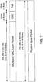
- FIG. 2illustrates the Forward channel structure, including Pilot, MAC, Control and Traffic channels.
- Processing of a Connection Layer (CL) packet 102includes first adding a security layer header 110 and tail 112 to the form a Security Layer (SL) packet 1 D4.
- the SL packet 104is then used to generate a Medium Access Control (MAC) layer packet 106, and finally a Physical Layer (PL) packet 108.
- the MAC layer 106 payloadis a fixed number of bits.
- the PL 108 payloadis then a multiple n times the length of the MAC layer 106 payload, plus the length of physical layer overhead (CRC tail bits etc.), wherein n is an integer.
- the limitations of the fixed MAC layer 106 payloadresults in inefficiencies in transmission and thus wasted bandwidth. For example, when the channel condition to a given user is "good as determined by Signal to Interference and Noise Ratio (SINR) or Data Rate Control (DRC) measure exceeding a threshold, there is a desire to transmit larger packets. For such a user, transmission of smaller blocks of data, such as voice packets, vocoder frames, etc., on the current forward link structure in IS-856 would result in wasted space in the MAC layer 106 packet. As the size of the data is much smaller than the fixed length of the MAC layer 106 packet, the remaining bits are filled with a padding. The result is inefficiency, as the MAC layer 106 packet is not fully utilized.
- SINRSignal to Interference and Noise Ratio
- DRCData Rate Control
- variable packet lengthfor HRD communications, wherein the variable length packets provide efficiency.
- variable length packetsprovide efficiency.
- MAC layer 106 packetsinto a single physical layer packet, allowing data for multiple users to be transmitted per packet.
- EP 0 912 016discloses a method for access control in a wireless network having a base station and a plurality of remote hosts includes the optional abilities of making dynamic adjustments of the uplink/downlink transmission ratio, making dynamic adjustments of the total number of reservation minislots, and assigning access priorities by message content type within a single user message stream.
- the method of the inventionfurther provides for remote wireless host paging and for delayed release of active channels by certain high priority users in order to provide low latency of real-time packets by avoiding the need for repeated channel setup signaling messages.
- FIG. 1is a portion of the air interface layering architecture of a High Rate Packet Data (HRPD) communication system.
- HRPDHigh Rate Packet Data
- FIG. 2is a forward channel structure for a HRPD communication system.
- FIG. 3is a security layer structure for a Format A connection layer packet.
- FIG. 4is a security layer structure for a Format B connection layer packet.
- FIGs. 5 and 6illustrate the generation for simplex and multiplex MAC packets from security layer packets.
- FIG. 7is a physical layer packet structure used to carry a single MAC layer packet of length less than 1000 bits.
- FIG. 8is a physical layer packet structure used to carry a single MAC layer packet of length equal to 1000 bits.
- FIG. 9is a physical layer packet structure used to carry multiple MAC layer packets of length equal to 1000 bits each.
- FIG. 10is a table of nominal data rates and data rate request interpretations.
- FIG. 11shows the compatibility between an explicit data rate indicator and data rate request values.
- FIG. 12illustrates generation of a physical layer packet based on a short security layer packet.
- FIG. 13illustrates generation of a 512-bit multiplexed physical layer packet containing payloads for two users.
- FIG. 14is a multiplex physical layer packet including different length security layer packets.
- FIG. 15is a physical layer packet including multiple medium access control layer capsules.
- FIGs. 16 and 17illustrate transmission of multiple slots to achieve a nominal data rate and a maximum data rate.
- FIG. 18is an access network according to one embodiment.
- FIG. 19is an access terminal according to one embodiment.
- An HDR subscriber stationreferred to herein as an access terminal (AT) may be mobile or stationary, and may communicate with one or more HDR base stations, referred to herein as modem pool transceivers (MPTs).
- An access terminaltransmits and receives data packets through one or more modem pool transceivers to an HDR base station controller, referred to herein as a modem pool controller (MPC).
- Modem pool transceivers and modem pool controllersare parts of a network called an access network.
- An Access Network (AN)transports data packets between multiple access terminals (ATs).
- the ANincludes network equipment providing connectivity between a packet switched data network and the AT.
- An ANis similar to a Base Station (BS), while an AT is similar to a Mobile Station (MS).
- BSBase Station
- MSMobile Station
- the access networkmay be further connected to additional networks outside the access network, such as a corporate intranet or the Internet, and may transport data packets between each access terminal and such outside networks.
- An access terminal that has established an active traffic channel connection with one or more modem pool transceiversis called an active access terminal, and is said to be in a traffic state.
- An access terminal that is in the process of establishing an active traffic channel connection with one or more modem pool transceiversis said to be in a connection setup state.
- An access terminalmay be any data device that communicates through a wireless channel or through a wired channel, for example using fiber optic or coaxial cables.
- An access terminalmay further be any of a number of types of devices including but not limited to PC card, compact flash, external or Internal modem, or wireless or wireline phone.
- the communication link through which the access terminal sends signals to the modem pool transceiveris called a reverse link.
- the communication link through which a modem pool transceiver sends signals to an access terminalis called
- the SL packet sizeis given as 1000 bits.
- the SL packetincludes an amount of overhead given as x bits. Alternate embodiments may provide an alternate length for the SL packet.
- FIG. 3 and FIG. 4illustrates two formats for data referred to as Format A and Format B.
- Format Ais defined as a SL packet having a one to one relation with the CL packet. In other words, the length of the CL packet is 1000 bits (i.e., the given size of the SL packet) minus x. In other words, the CL packet plus the SL overhead is equal to the given length of the SL packet.
- Format Bis defined as 1) a SL packet which includes padding, or 2) a SL packet which includes multiple CL packets with or without padding.
- the size of the SL packetmay be variable.
- FIG. 3illustrates a Format A packet wherein the SL packet is one of four sizes.
- the size of the SL packetmay be one of: 112, 240, 488, or 1000 bits.
- the SLis made up of the CL packet. There is one CL packet corresponding to one user. Data is processed as illustrated in FIG. 1 , wherein processing of a Connection Layer (CL) packet 102 includes concatenating one or more Connection Layer packets, together with padding if necessary, and then adding a security layer header 110 and tail 112 to the form a Security Layer (SL) packet 104.
- CLConnection Layer
- SLSecurity Layer
- FIG. 4illustrates a Format B packet wherein the SL packet is variable, and the SL payload includes one or more CL packets plus padding.
- the resultant SL packet sizeis one of 112, 240, 488, or 1000 bits.
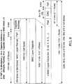
- FIG. 5illustrates processing of SL packets, wherein the SL packets have a length less than 1000 bits.
- Two fieldsare appended to the SL packet, a SubPacket Identification (SPID) or MAC index value, which is 6 bits long, and a LENgth indicator (LEN), which are two bits.
- the MAC indexidentifies the user to whom the packet is directed.
- the MAC index fieldis used to identify the user to whom the packet is destined.
- LENspecifies the format.
- the LEN fieldis used to specify whether the SL packet is of Format A or Format B. If the SL packet is of format A, the LEN also specifies the length of the SL packet, which could take on one of three values: 112, 240, 488.
- the resultant MAC layer subpacketis 120, 248, or 496 bits long.
- the MAC layer subpacketis then processed to form the MAC layer packet by determining if multiple MAC layer subpackets are to be combined.
- the MAC layer packetincludes one or more MAC layer subpackets plus an inner Cyclic Redundancy Check value along with any necessary padding.
- the MAC layer packetis referred to as Multiplex if containing more than one SL packet, possibly for different users.
- a CRC value and a tail valueare applied to the MAC layer packet to form a PL layer packet as illustrated in FIG. 7 .
- the resultant PL packetis then 152, 280, or 528 bits long.
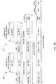
- FIG. 6illustrates processing of SL packets, wherein the SL packets have a length equal to 1000 bits.
- the MAC layer payloadis the SL packet.
- the MAC layer packetis referred to as Simplex.
- FIG. 8illustrates processing of MAC layer packets wherein the MAC layer packet has a length of 1000 bits.
- the processing of FIG. 8may be used for Format A or Format B SL packets.
- a CRC value and a tailare applied to the MAC layer packet.
- a format indicator (FMT), of 2 bits,is also applied.
- the significance of the FMTis given as in Table I.
- a simplex MAC packetcontains exactly one SL packet; and a multiplex MAC packet contains two or more SL packets.
- a capsuleis defined as a MAC packet, followed by a few bits of overhead, which carry information specific to that MAC packet, e.g. FIG. 15 illustrates a single PL packet carries multiple MAC layer packets.
- a MAC capsuleis used when a PL packet carries two or more MAC packets. The capsule is used to identify the individual capsules and is, therefore, used only in case of a multiplex packet.
- the size of the PL packetmay be increased to accommodate larger transfers.
- the larger PL packetalso allows for multiple MAC packets to be embedded within one PL packet. Specifically, multiple MAC packets with multiple destination addresses may each be embedded in a subpacket. In this way, one PL packet is transmitted to multiple users.
- a capsuleis given including a MAC layer packet, the FMT and a capsule address. The interpretation of the FMT field is as specified in Table 1. The capsule address provides the destination of the MAC layer packet. Note that if the MAC layer packet is a multiplex packet, i.e., including multiple CL layer packets each having a different destination address, the capsule address may be left blank.
- the capsule addresshas little meaning, as it may only designate one user.
- the capsule addressis 6 bits in the present example.
- the composite of the MAC layer packet, FMT and capsule addressforms the MAC layer capsule.
- multiple MAC layer capsulesmay be concatenated.
- a CRC valuei.e., pad, CRC and tail
- the paddingmay be included such that the MAC layer capsule overhead, i.e., pad, CRC and tail, has a length of 16*n bits.
- the specific lengthis a design choice, determined by the number of bits leftover in the PL packet after the MAC capsules and tail bits are included.
- the PL packet of length 2048 bitsuses a 24-bit CRC, while longer PL packets use a 32-bit CRC.
- there are four extended lengths for the PL packet2048, 3072, 4096 and 5120 bits.
- FIG. 10is a table of nominal data rates corresponding to the extended PL packets, which are recently defined with respect to HRPD in IS-856.
- PL packet lengthsas given in FIG. 7 , a packet length of 152 bits is transmitted and incrementally retransmitted over 4 slots, for a nominal transmission data rate of 19.2 kbps.
- calculation of data ratesadopts the convention of rounding down the PL packet length to the nearest power of two.
- Each slot in a 1xEV-DO systemis 1.666ms long. For good channel conditions, the data rate may be increased to 76.8 kbps through the use of early termination.
- Early terminationrefers to a system wherein the receiver of the data transmits an acknowledgement or ACK when the data has been received and decoded correctly. In this way, all four attempts may not be used for transmission. Such acknowledgement terminates any further transmission of the packet.
- packet lengths of 280 and 528 bitsare each transmitted over 6 slots, resulting in nominal data rates of 25.6 kbps, and 57.6 kbps, respectively.
- eachmay have a maximum data rate of 153.6 kbps, and 307.2 kbps, respectively, given early termination.
- termination after the first slotresults in a maximum data rate of 76.8 kbps.
- termination after the second slotresults in a maximum data rate of 38.4 kbps, or half the maximum data rate. If all four slots are transmitted, the nominal data rate of 19.2 kbps is realized.
- FIG. 17illustrates the transmission of 280 bits per packet per slot, wherein the transmission and incremental retransmission is over 6 slots.
- the nominal data rateis 25.6 kbps. Termination after the first slot results in a maximum data rate of 153.6 kbps, while termination after the third slot results in a data rate of 115.2 kbps, or half the maximum. If all 6 slots are transmitted, the nominal data rate of 25.6 kbps is realized.
- the ATprovides a data rate request to the AN, wherein the data rate request is transmitted on the Reverse Link (RL), and specifically on a Data Request Channel (DRC).
- the data rate requestmay be calculated as a function of the received signal quality at the AT.
- the ATdetermines a maximum data rate at which the AT may receive data.
- the maximum data rateis then requested by the AT for data transmissions from the AN.
- the data rate requestis received by the AN, which then selects a packet size accordingly.
- the ANmay generate a shorter PL packet, a conventional PL packet, or a longer PL packet.
- Each data rate requestcorresponds to one or more packet sizes. This choice depends on the QoS for the flow in question.
- the ANmay transmit a simplex PL packet of length 152 bits to effect the 19.2 kbps or may transmit a PL packet of length 280 bits for an effective data rate of 25.6 kbps.
- the AThas knowledge of the possible PL packet sizes and data rates, the AT does not have specific knowledge as to which one is currently being used. In one embodiment, the AT tries each potential PL packet size. Note that smaller packet lengths tend to reduce loss as less information is retransmitted if not correctly received. Similarly, there is a better chance of decoding at lower data rates.
- the time taken to transmit the shorter packetsis a fraction of that required for longer packets given identical channel conditions.
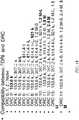
- Multi-valued data rate requestsare sent via the DRC data rate request, wherein the correspondence is given in Table II.
- the designation "(L)"indicates an extended PL packet length.
- DRC0corresponds to 19.2 kbps and 25.6 kbps.
- the PL packetcontains 152 bits and is transmitted over 4 slots.
- the PL packetcontains 280 bits and is transmitted over 6 slots.
- the indicator (L)is included in the table entry.
- DRC5corresponds to 307.2 kbps, wherein the PL packet length is 2048 bits.
- DRC7corresponds to 614 kbps, wherein the PL packet length is 2048 bits.
- packet division multiplexingis available when a DRC data rate request indicates a data rate greater than or equal to 153kbps, or another predetermined value.
- a single PL packet of 1024 bits or moreis composed of one or more MAC layer capsule(s). Each capsule then contains MAC layer packets to one or more users.
- each access probeenables a pilot (I-channel), which functions as a preamble.
- a modified preambleincludes an Explicit Data Rate Indicator (EDRI).
- EDRIExplicit Data Rate Indicator
- the encoder packetssupport multiplex of data into one packet. At higher data rates, the preamble includes an EDRI field on the modulation phase Q branch.
- the EDRIis (8,4,4) bi-orthogonal coded and block repeated 8 times.
- the EDRIspecifies one of a plurality of rates.
- the preambletransmits the MAC index on the I-branch.
- the MAC index(assigned to a given terminal by the AN) is a 6-bit number used by the AN to Walsh cover the packet (with the corresponding 64-ary Walsh cover) to aid the AT in identifying packets directed to thereto. This mechanism is used for a unicast packet.
- the preambletransmits the EDRI on the Q-branch, wherein all users with DRC compatible with EDRI attempt to decode the packet.
- FIG. 11lists the set of data rates that are compatible with each DRC.
- a data rateis said to be compatible with a DRC, if the packet corresponding to that data rate may be reliably decoded by any user capable of decoding (reliably) a packet with that DRC.
- the data rate compatible with a DRCis at most equal to that of a packet associated with the given DRC, and the duration of the packet is at least as long as that of a packet associated with the given DRC. In other words, if the user can decode a packet for that DRC it can decode a packet with all the data rates that are compatible with that DRC.
- an ACKnowledgement (ACK) indicatoris provided for MAC layer retransmission, referred to as D-ARQ.
- the ACKis transmitted on the Reverse Link by those users able to decode the PL packet, wherein the packet contains a MAC layer packet or subpacket addressed thereto.
- the ACK transmissionis boosted by 3dB to allow for On-Off keying.
- the ACKis indicated by the presence of a signal and the NACK by the absence of the signal.
- ACK and NAKare indicated by transmitted different signals, of equal strength and opposite sign relative to each other.
- one of the messagesis indicated by transmitting a non-trivial signal
- the other messageis indicated by transmitting no signal.
- ON-OFF signalingis used for ARQ of multi-user packets
- bipolar signalingis used for ARQ of single-user packets.
- the ACKis transmitted two slots after transmission of the packet, i.e., In the third time-slot. This is done so as to allow time for demodulation and decoding of the packet by the AT.
- the ACKis transmitted at a time slot, which is delayed by 4 slots from that of the single user packet.
- the SL packetis 240 bits.
- the SL packetis a Format A packet
- the target PL packetis 280 bits
- the LEN fieldis 2 bits and the SPID field is 6 bits, resulting in a modified packet of 248 bits.
- An Inner CRC (8 bits)is appended, and in addition a 16-bit CRC plus an 8-bit tail are added resulting in a 280 PL packet.
- two 240-bit SL packetsare multiplexed to form a 528-bit PL packet.
- the SL packet 200is a Format A packet from a first user.
- the SL packet 220is a Format B packet from a second user.
- the multiplexed packetthen includes an SPID and LEN for each of packets 200 and 220.
- An inner CRC(8 bits), a CRC (16 bits), and a tail (8 bits) are added to the multiplexed packet resulting in a PL packet of 528 bits.
- four same format packetse.g., Format A packets, each from different users, are multiplexed into a 1024-bit PL packet as illustrated in FIG. 14 .
- Each SL packethas a corresponding MAC ID value.
- the SL packetsare of various lengths, including a first SL packet of 488 bits, a second SL packet of 240 bits, and two SL packets of 112 bits.
- a SPID and LENare applied to each SL packet to form a multiplexed packet.
- An inner CRC, CRC and Tailare then applied to the multiplexed packet to form a PL packet.
- a format field, FMTis also included. As indicated in Table 1 given hereinabove, the FMT value identifies the PL packet as a multiplexed packet.
- different format packetse.g., Format A and Format B packets, are multiplexed to form a 2048-bit PL packet.
- a first SL packethas 1000 bits, wherein the second and third SL packets are 488 bits each.
- the first SL packet 300is used to generate a first capsule, and the second and third packets 320, 340 are used to generate a second capsule.
- the SL packet 300is 1000 bits and therefore may compose a single capsule.
- the SL packets 320, 340are less than 1000 bits and are therefore one capsule includes both packets.
- a FMT and capsule addressis applied to the first SL packet 300 to form a first capsule.
- the second capsuleis multiplexed capsule including the SL packets 320, 340.
- an SPID and LENTo each of the SL packets 320, 340 are added an SPID and LEN. A second capsule address is then provided for the second capsule.
- the second capsule addressis cleared indicating that data for multiple recipients are included in the capsule.
- FIG. 18illustrates a wireless infrastructure element 400, including transmit circuitry (Tx) 402, and receive circuitry (Rx) 418 coupled to a communication bus 420.
- a DRC unit 410receives the DRC data rate request as received on the DRC channel from ATs.
- the element 400further includes a Central Processing Unit (CPU) 412 and a memory 406.
- the PL packet generation 404receives the DRC data rate request from DRC unit 410 and composes the PL packet.
- the PL packet generation 404may generate a simplex packet or a multiplex packet, and further may implement any of the methods described hereinabove.
- FIG. 1illustrates a wireless infrastructure element 400, including transmit circuitry (Tx) 402, and receive circuitry (Rx) 418 coupled to a communication bus 420.
- a DRC unit 410receives the DRC data rate request as received on the DRC channel from ATs.
- the element 400further includes a Central Processing Unit (CPU) 412 and a memory 406.
- the AT 500includes transmit circuitry (Tx) 502, and receive circuitry (Rx) 518 coupled to a communication bus 520.
- a DRC unit 510determines the maximum data rate and transmits the corresponding request on the DRC channel from ATs.
- the element 500further includes a Central Processing Unit (CPU) 512 and a memory 506.
- the PL packet interpretation 504receives the PL packet from the AN and determines if any content is directed to AT 500. Further the PL packet interpretation 504 determines the transmission rate of the received PL packet.
- the PL packet interpretation 504may process a simplex packet or a multiplex packet, and further may implement any of the methods described hereinabove.
- a mechanism for supporting multi-user packets in the context of 1xEV-DO systemprovides for a modified Preamble structure (Unicast v/s multi-user packets), a modified Rate Set, and/or a modified mechanism for identifying ACK from a single-user packet or a multiplexed packet (delayed ACK).
- a modified Preamble structureUnicast v/s multi-user packets
- a modified Rate Setand/or a modified mechanism for identifying ACK from a single-user packet or a multiplexed packet (delayed ACK).
- DSPdigital signal processor
- ASICapplication specific integrated circuit
- FPGAfield programmable gate array
- a general purpose processormay be a microprocessor, but in the alternative, the processor may be any conventional processor, controller, microcontroller, or state machine.
- a processormay also be implemented as a combination of computing devices, e.g., a combination of a DSP and a microprocessor, a plurality of microprocessors, one or more microprocessors in conjunction with a DSP core, or any other such configuration.
- a software modulemay reside in RAM memory, flash memory, ROM memory, EPROM memory, EEPROM memory, registers, hard disk, a removable disk, a CD-ROM, or any other form of storage medium known in the art.
- An exemplary storage mediumis coupled to the processor such the processor can read information from, and write information to, the storage medium.
- the storage mediummay be integral to the processor.
- the processor and the storage mediummay reside in an ASIC.
- the ASICmay reside in a user terminal.
- the processor and the storage mediummay reside as discrete components in a user terminal.
Landscapes
- Engineering & Computer Science (AREA)
- Computer Networks & Wireless Communication (AREA)
- Signal Processing (AREA)
- Mobile Radio Communication Systems (AREA)
- Data Exchanges In Wide-Area Networks (AREA)
- Communication Control (AREA)
Abstract
Description
- The present invention relates generally to communication systems, and more specifically to variable packet lengths for application to a high rate packet data communications.
- High Rate Packet Data (HRPD) communications are optimized for bulk data transport. One HRPD system is detailed in the cdma2000, standard referred to as 1xEV-DO and specified in TIA/EIA IS-856 entitled "cdma2000 High Rate Packet Data Air Interface Specification."
FIG. 1 illustrates the air interface layering architecture for a 1xEV-DO system. The Connection layer (CL) provides air link connection establishment and maintenance services. The Security Layer (SL) provides encryption and authentication services. The Physical Layer (PL) provides the channel structure, frequency, power output, modulation and encoding specifications for the Forward and Reverse channels. The Medium Access Control (MAC) layer defines procedures to receive and transmit over the Physical Layer.FIG. 2 illustrates the Forward channel structure, including Pilot, MAC, Control and Traffic channels. - Data is processed as illustrated in
FIG. 1 , wherein processing of a Connection Layer (CL)packet 102 includes first adding asecurity layer header 110 andtail 112 to the form a Security Layer (SL)packet 1 D4. TheSL packet 104 is then used to generate a Medium Access Control (MAC)layer packet 106, and finally a Physical Layer (PL)packet 108. TheMAC layer 106 payload is a fixed number of bits. ThePL 108 payload is then a multiple n times the length of theMAC layer 106 payload, plus the length of physical layer overhead (CRC tail bits etc.), wherein n is an integer. - The limitations of the
fixed MAC layer 106 payload results in inefficiencies in transmission and thus wasted bandwidth. For example, when the channel condition to a given user is "good as determined by Signal to Interference and Noise Ratio (SINR) or Data Rate Control (DRC) measure exceeding a threshold, there is a desire to transmit larger packets. For such a user, transmission of smaller blocks of data, such as voice packets, vocoder frames, etc., on the current forward link structure in IS-856 would result in wasted space in theMAC layer 106 packet. As the size of the data is much smaller than the fixed length of theMAC layer 106 packet, the remaining bits are filled with a padding. The result is inefficiency, as theMAC layer 106 packet is not fully utilized. - There is a need, therefore, for a variable packet length for HRD communications, wherein the variable length packets provide efficiency. There is further a need to combine
smaller MAC layer 106 packets into a single physical layer packet, allowing data for multiple users to be transmitted per packet. EP 0 912 016N 1=N. In an alternate embodiment of a method for access control according to the present invention, each remote host of access priority class i and with a stack level that equals 0, then transmits an access request with a probability Pi where P(i+1) < Pi and P1=1.FIG. 1 is a portion of the air interface layering architecture of a High Rate Packet Data (HRPD) communication system.FIG. 2 is a forward channel structure for a HRPD communication system.FIG. 3 is a security layer structure for a Format A connection layer packet.FIG. 4 is a security layer structure for a Format B connection layer packet.FIGs. 5 and 6 illustrate the generation for simplex and multiplex MAC packets from security layer packets.FIG. 7 is a physical layer packet structure used to carry a single MAC layer packet of length less than 1000 bits.FIG. 8 is a physical layer packet structure used to carry a single MAC layer packet of length equal to 1000 bits.FIG. 9 is a physical layer packet structure used to carry multiple MAC layer packets of length equal to 1000 bits each.FIG. 10 is a table of nominal data rates and data rate request interpretations.FIG. 11 shows the compatibility between an explicit data rate indicator and data rate request values.FIG. 12 illustrates generation of a physical layer packet based on a short security layer packet.FIG. 13 illustrates generation of a 512-bit multiplexed physical layer packet containing payloads for two users.FIG. 14 is a multiplex physical layer packet including different length security layer packets.FIG. 15 is a physical layer packet including multiple medium access control layer capsules.FIGs. 16 and 17 illustrate transmission of multiple slots to achieve a nominal data rate and a maximum data rate.FIG. 18 is an access network according to one embodiment.FIG. 19 is an access terminal according to one embodiment.- The word "exemplary" is used herein to mean "serving as an example, instance, or illustration." Any embodiment described herein as "exemplary" is not necessarily to be construed as preferred or advantageous over other embodiments.
- An HDR subscriber station, referred to herein as an access terminal (AT), may be mobile or stationary, and may communicate with one or more HDR base stations, referred to herein as modem pool transceivers (MPTs). An access terminal transmits and receives data packets through one or more modem pool transceivers to an HDR base station controller, referred to herein as a modem pool controller (MPC). Modem pool transceivers and modem pool controllers are parts of a network called an access network. An Access Network (AN) transports data packets between multiple access terminals (ATs). The AN includes network equipment providing connectivity between a packet switched data network and the AT. An AN is similar to a Base Station (BS), while an AT is similar to a Mobile Station (MS).
- The access network may be further connected to additional networks outside the access network, such as a corporate intranet or the Internet, and may transport data packets between each access terminal and such outside networks. An access terminal that has established an active traffic channel connection with one or more modem pool transceivers is called an active access terminal, and is said to be in a traffic state. An access terminal that is in the process of establishing an active traffic channel connection with one or more modem pool transceivers is said to be in a connection setup state. An access terminal may be any data device that communicates through a wireless channel or through a wired channel, for example using fiber optic or coaxial cables. An access terminal may further be any of a number of types of devices including but not limited to PC card, compact flash, external or Internal modem, or wireless or wireline phone. The communication link through which the access terminal sends signals to the modem pool transceiver is called a reverse link. The communication link through which a modem pool transceiver sends signals to an access terminal is called a forward link.
- In the following discussion, the SL packet size is given as 1000 bits. The SL packet includes an amount of overhead given as x bits. Alternate embodiments may provide an alternate length for the SL packet.
FIG. 3 and FIG. 4 illustrates two formats for data referred to as Format A and Format B. Format A is defined as a SL packet having a one to one relation with the CL packet. In other words, the length of the CL packet is 1000 bits (i.e., the given size of the SL packet) minus x. In other words, the CL packet plus the SL overhead is equal to the given length of the SL packet. Format B is defined as 1) a SL packet which includes padding, or 2) a SL packet which includes multiple CL packets with or without padding. - According to one embodiment, the size of the SL packet may be variable.
FIG. 3 illustrates a Format A packet wherein the SL packet is one of four sizes. The size of the SL packet may be one of: 112, 240, 488, or 1000 bits. The SL is made up of the CL packet. There is one CL packet corresponding to one user. Data is processed as illustrated inFIG. 1 , wherein processing of a Connection Layer (CL)packet 102 includes concatenating one or more Connection Layer packets, together with padding if necessary, and then adding asecurity layer header 110 andtail 112 to the form a Security Layer (SL)packet 104. FIG. 4 illustrates a Format B packet wherein the SL packet is variable, and the SL payload includes one or more CL packets plus padding. The resultant SL packet size is one of 112, 240, 488, or 1000 bits.FIG. 5 illustrates processing of SL packets, wherein the SL packets have a length less than 1000 bits. Two fields are appended to the SL packet, a SubPacket Identification (SPID) or MAC index value, which is 6 bits long, and a LENgth indicator (LEN), which are two bits. The MAC index identifies the user to whom the packet is directed. The MAC index field is used to identify the user to whom the packet is destined. LEN specifies the format. The LEN field is used to specify whether the SL packet is of Format A or Format B. If the SL packet is of format A, the LEN also specifies the length of the SL packet, which could take on one of three values: 112, 240, 488. The resultant MAC layer subpacket is 120, 248, or 496 bits long. The MAC layer subpacket is then processed to form the MAC layer packet by determining if multiple MAC layer subpackets are to be combined. The MAC layer packet includes one or more MAC layer subpackets plus an inner Cyclic Redundancy Check value along with any necessary padding. The MAC layer packet is referred to as Multiplex if containing more than one SL packet, possibly for different users. A CRC value and a tail value are applied to the MAC layer packet to form a PL layer packet as illustrated inFIG. 7 . The resultant PL packet is then 152, 280, or 528 bits long.FIG. 6 illustrates processing of SL packets, wherein the SL packets have a length equal to 1000 bits. The MAC layer payload is the SL packet. The MAC layer packet is referred to as Simplex.FIG. 8 illustrates processing of MAC layer packets wherein the MAC layer packet has a length of 1000 bits. The processing ofFIG. 8 may be used for Format A or Format B SL packets. A CRC value and a tail are applied to the MAC layer packet. Additionally, a format indicator (FMT), of 2 bits, is also applied. The significance of the FMT is given as in Table I.Table I: Format field (FMT) Definitions 01 = Format A Simplex 11 = Format B Simplex 00 = Multiplex MAC packet 10 = Invalid MAC packet FIG. 15 illustrates a single PL packet carries multiple MAC layer packets. A MAC capsule is used when a PL packet carries two or more MAC packets. The capsule is used to identify the individual capsules and is, therefore, used only in case of a multiplex packet.- According to one embodiment, the size of the PL packet may be increased to accommodate larger transfers. The larger PL packet also allows for multiple MAC packets to be embedded within one PL packet. Specifically, multiple MAC packets with multiple destination addresses may each be embedded in a subpacket. In this way, one PL packet is transmitted to multiple users. As illustrated in
FIG. 9 , a capsule is given including a MAC layer packet, the FMT and a capsule address. The interpretation of the FMT field is as specified in Table 1. The capsule address provides the destination of the MAC layer packet. Note that if the MAC layer packet is a multiplex packet, i.e., including multiple CL layer packets each having a different destination address, the capsule address may be left blank. In other words, if the PL packet will include information for multiple users, then the capsule address has little meaning, as it may only designate one user. The capsule address is 6 bits in the present example. The composite of the MAC layer packet, FMT and capsule address forms the MAC layer capsule. - Continuing with
FIG. 9 , multiple MAC layer capsules may be concatenated. To the combination of MAC layer capsules is added a CRC value, a tail, and any necessary padding. The padding may be included such that the MAC layer capsule overhead, i.e., pad, CRC and tail, has a length of 16*n bits. The specific length is a design choice, determined by the number of bits leftover in the PL packet after the MAC capsules and tail bits are included. Whenever there are enough bits left, it is desirable to use 32-bit CRC. In the present example the PL packet oflength 2048 bits uses a 24-bit CRC, while longer PL packets use a 32-bit CRC. In the present example, there are four extended lengths for the PL packet: 2048, 3072, 4096 and 5120 bits. FIG. 10 is a table of nominal data rates corresponding to the extended PL packets, which are recently defined with respect to HRPD in IS-856. Referring to the PL packet lengths as given inFIG. 7 , a packet length of 152 bits is transmitted and incrementally retransmitted over 4 slots, for a nominal transmission data rate of 19.2 kbps. Note that according to one embodiment, calculation of data rates adopts the convention of rounding down the PL packet length to the nearest power of two. Each slot in a 1xEV-DO system is 1.666ms long. For good channel conditions, the data rate may be increased to 76.8 kbps through the use of early termination. Early termination refers to a system wherein the receiver of the data transmits an acknowledgement or ACK when the data has been received and decoded correctly. In this way, all four attempts may not be used for transmission. Such acknowledgement terminates any further transmission of the packet. Similarly, packet lengths of 280 and 528 bits are each transmitted over 6 slots, resulting in nominal data rates of 25.6 kbps, and 57.6 kbps, respectively. Similarly, each may have a maximum data rate of 153.6 kbps, and 307.2 kbps, respectively, given early termination.- Referring to
FIG. 16 , for 152 bits per packet per slot having a nominal data rate of 19.2 kbps, termination after the first slot results in a maximum data rate of 76.8 kbps. Early termination after the second slot results in a maximum data rate of 38.4 kbps, or half the maximum data rate. If all four slots are transmitted, the nominal data rate of 19.2 kbps is realized. FIG. 17 illustrates the transmission of 280 bits per packet per slot, wherein the transmission and incremental retransmission is over 6 slots. Here the nominal data rate is 25.6 kbps. Termination after the first slot results in a maximum data rate of 153.6 kbps, while termination after the third slot results in a data rate of 115.2 kbps, or half the maximum. If all 6 slots are transmitted, the nominal data rate of 25.6 kbps is realized.- In a 1xEV-DO system, the AT provides a data rate request to the AN, wherein the data rate request is transmitted on the Reverse Link (RL), and specifically on a Data Request Channel (DRC). The data rate request may be calculated as a function of the received signal quality at the AT. The AT determines a maximum data rate at which the AT may receive data. The maximum data rate is then requested by the AT for data transmissions from the AN. The data rate request is received by the AN, which then selects a packet size accordingly. For a given data rate request, the AN may generate a shorter PL packet, a conventional PL packet, or a longer PL packet. Each data rate request corresponds to one or more packet sizes. This choice depends on the QoS for the flow in question.
- For example, as given in
FIG. 10 , for a data rate request of 19.2kbps, referred to as "DRC0," the AN may transmit a simplex PL packet oflength 152 bits to effect the 19.2 kbps or may transmit a PL packet oflength 280 bits for an effective data rate of 25.6 kbps. While the AT has knowledge of the possible PL packet sizes and data rates, the AT does not have specific knowledge as to which one is currently being used. In one embodiment, the AT tries each potential PL packet size. Note that smaller packet lengths tend to reduce loss as less information is retransmitted if not correctly received. Similarly, there is a better chance of decoding at lower data rates. In addition, the time taken to transmit the shorter packets (in case of no early termination) is a fraction of that required for longer packets given identical channel conditions. - Multi-valued data rate requests are sent via the DRC data rate request, wherein the correspondence is given in Table II. The designation "(L)" indicates an extended PL packet length. The data rate values 19.2 kbps, 28.2 kbps, and 57.6 kbps, each refer to the bit length as given in
FIG. 10 , respectively. For example, DRC0 corresponds to 19.2 kbps and 25.6 kbps. For data transmissions having a nominal data rate of 19.2 kbps, the PL packet contains 152 bits and is transmitted over 4 slots. For data transmissions having a nominal data rate of 25.6 kbps, the PL packet contains 280 bits and is transmitted over 6 slots. When a full length, or extended length packet is used, the indicator (L) is included in the table entry. For example, DRC5 corresponds to 307.2 kbps, wherein the PL packet length is 2048 bits. Similarly, DRC7 corresponds to 614 kbps, wherein the PL packet length is 2048 bits.Table II DRC data rate request rate (kbps) rate (kbps) rate (kbps) rate (kbps) DRC0 19.2 25.6 --- --- DRC1 19.2 25.6 25.6 (L) --- DRC2 19.2 25.6 57.6 76.8 DRC3 19.2 25.6 57.6 153.6 DRC4 25.6 57.6 307.2 --- DRC5 25.6 57.6 307.2 (L) --- DRC6 57.6 614.4 --- --- DRC7 57.6 614 (L) --- --- - Generally, packet division multiplexing is available when a DRC data rate request indicates a data rate greater than or equal to 153kbps, or another predetermined value. For multiplexing, a single PL packet of 1024 bits or more is composed of one or more MAC layer capsule(s). Each capsule then contains MAC layer packets to one or more users. In one HRPD system, each access probe enables a pilot (I-channel), which functions as a preamble. According to one embodiment, a modified preamble includes an Explicit Data Rate Indicator (EDRI). The encoder packets support multiplex of data into one packet. At higher data rates, the preamble includes an EDRI field on the modulation phase Q branch. The EDRI is (8,4,4) bi-orthogonal coded and block repeated 8 times. The EDRI specifies one of a plurality of rates. To check if a packet is for a given user, the user will check the MAC layer identifiers. For a single user packet, the preamble transmits the MAC index on the I-branch. The MAC index (assigned to a given terminal by the AN) is a 6-bit number used by the AN to Walsh cover the packet (with the corresponding 64-ary Walsh cover) to aid the AT in identifying packets directed to thereto. This mechanism is used for a unicast packet. For multi-user packets, the preamble transmits the EDRI on the Q-branch, wherein all users with DRC compatible with EDRI attempt to decode the packet.
- Potential data rates and corresponding EDRI Length (in chips) are given as: 153.6 k (256), 307.2 k-L (256), 307.2 k(128), 614 k-L (128), 921k (128), 1.2M-L (128), 614 k (64), 1.2M (64), 1.5 M (128), 1.8M (64), 2.4M (64), 3.0M (64), and are further illustrated in
FIG. 11. FIG. 11 lists the set of data rates that are compatible with each DRC. A data rate is said to be compatible with a DRC, if the packet corresponding to that data rate may be reliably decoded by any user capable of decoding (reliably) a packet with that DRC. Generally, the data rate compatible with a DRC is at most equal to that of a packet associated with the given DRC, and the duration of the packet is at least as long as that of a packet associated with the given DRC. In other words, if the user can decode a packet for that DRC it can decode a packet with all the data rates that are compatible with that DRC. - For multiplexed packets, and specifically for multi-user packets, an ACKnowledgement (ACK) indicator is provided for MAC layer retransmission, referred to as D-ARQ. The ACK is transmitted on the Reverse Link by those users able to decode the PL packet, wherein the packet contains a MAC layer packet or subpacket addressed thereto. The ACK transmission is boosted by 3dB to allow for On-Off keying. The ACK is indicated by the presence of a signal and the NACK by the absence of the signal. In bi-polar keying, ACK and NAK are indicated by transmitted different signals, of equal strength and opposite sign relative to each other. In contrast, with on-off keying, one of the messages (ACK) is indicated by transmitting a non-trivial signal, while the other message (NAK) is indicated by transmitting no signal. ON-OFF signaling is used for ARQ of multi-user packets, while bipolar signaling is used for ARQ of single-user packets. For single user packets, i.e., unicast transmission, the ACK is transmitted two slots after transmission of the packet, i.e., In the third time-slot. This is done so as to allow time for demodulation and decoding of the packet by the AT. For multi-user packets, the ACK is transmitted at a time slot, which is delayed by 4 slots from that of the single user packet. When a multi-user packet is directed to a first AT, and the AN does not receive an ACK from that AT, the AN will not send a unicast packet to that AT during the next slot on the same interlace offset. This is to disambiguate the meaning of the ACK that is sent on the 7th slot after the transmission of the multi-user packet. Referring again to the packet construction procedures described hereinabove, in a first example of packet encapsulation illustrated in
FIG. 12 ,
the SL packet is 240 bits. The SL packet is a Format A packet, the target PL packet is 280 bits, and the MAC ID=8. The SL packet is processed by adding two fields: SPID and LEN, as described hereinabove. The LEN field is 2 bits and the SPID field is 6 bits, resulting in a modified packet of 248 bits. An Inner CRC (8 bits) is appended, and in addition a 16-bit CRC plus an 8-bit tail are added resulting in a 280 PL packet. In a second example, illustrated inFIG. 13 , two 240-bit SL packets are multiplexed to form a 528-bit PL packet. Afirst SL packet 200 is 240 bits and has a MAC ID = 8. TheSL packet 200 is a Format A packet from a first user. TheSL packet 220 is a Format B packet from a second user. TheSL packet 220 is also 240 bits, but has a MAC ID = 5. The multiplexed packet then includes an SPID and LEN for each ofpackets FIG. 14 . Each SL packet has a corresponding MAC ID value. The SL packets are of various lengths, including a first SL packet of 488 bits, a second SL packet of 240 bits, and two SL packets of 112 bits. A SPID and LEN are applied to each SL packet to form a multiplexed packet. An inner CRC, CRC and Tail are then applied to the multiplexed packet to form a PL packet. In this example, a format field, FMT, is also included. As indicated in Table 1 given hereinabove, the FMT value identifies the PL packet as a multiplexed packet. In a fourth example, illustrated inFIG. 15 , different format packets, e.g., Format A and Format B packets, are multiplexed to form a 2048-bit PL packet. A first SL packet has 1000 bits, wherein the second and third SL packets are 488 bits each. Thefirst SL packet 300 is used to generate a first capsule, and the second andthird packets SL packet 300 is 1000 bits and therefore may compose a single capsule. TheSL packets first SL packet 300 to form a first capsule. The second capsule is multiplexed capsule including theSL packets SL packets FIG. 18 illustrates awireless infrastructure element 400, including transmit circuitry (Tx) 402, and receive circuitry (Rx) 418 coupled to acommunication bus 420. ADRC unit 410 receives the DRC data rate request as received on the DRC channel from ATs. Theelement 400 further includes a Central Processing Unit (CPU) 412 and amemory 406. ThePL packet generation 404 receives the DRC data rate request fromDRC unit 410 and composes the PL packet. ThePL packet generation 404 may generate a simplex packet or a multiplex packet, and further may implement any of the methods described hereinabove.FIG. 19 illustrates anAT 500 according to one embodiment TheAT 500 includes transmit circuitry (Tx) 502, and receive circuitry (Rx) 518 coupled to acommunication bus 520. ADRC unit 510 determines the maximum data rate and transmits the corresponding request on the DRC channel from ATs. Theelement 500 further includes a Central Processing Unit (CPU) 512 and amemory 506. ThePL packet interpretation 504 receives the PL packet from the AN and determines if any content is directed toAT 500. Further thePL packet interpretation 504 determines the transmission rate of the received PL packet. ThePL packet interpretation 504 may process a simplex packet or a multiplex packet, and further may implement any of the methods described hereinabove. As described hereinabove, methods and apparatus are providing multi-user packets on a forward link in order to improve packing efficiency. In one embodiment, shorter packets are provided to users either in poor channel conditions or users that require smaller amounts of data due to the applications and the corresponding Quality of Service (QoS) requirements. In another embodiment, a mechanism for supporting multi-user packets in the context of 1xEV-DO system provides for a modified Preamble structure (Unicast v/s multi-user packets), a modified Rate Set, and/or a modified mechanism for identifying ACK from a single-user packet or a multiplexed packet (delayed ACK). ON/OFF keying for ACK channel v/s bi-polar keying used in IS-856, and/or a multi-valued interpretation of DRC - Those of skill in the art would understand that information and signals may be represented using any of a variety of different technologies and techniques. For example, data, instructions, commands, information, signals, bits, symbols, and chips that may be referenced throughout the above description may be represented by voltages, currents, electromagnetic waves, magnetic fields or particles, optical fields or particles, or any combination thereof.
- Those of skill would further appreciate that the various illustrative logical blocks, modules, circuits, and algorithm steps described in connection with the embodiments disclosed herein may be implemented as electronic hardware, computer software, or combinations of both. To clearly illustrate this interchangeability of hardware and software, various illustrative components, blocks, modules, circuits, and steps have been described above generally in terms of their functionality. Whether such functionality is implemented as hardware or software depends upon the particular application and design constraints imposed on the overall system. Skilled artisans may implement the described functionality in varying ways for each particular application, but such implementation decisions should not be interpreted as causing a departure from the scope of the present invention.
- The various illustrative logical blocks, modules, and circuits described in connection with the embodiments disclosed herein may be implemented or performed with a general purpose processor, a digital signal processor (DSP), an application specific integrated circuit (ASIC), a field programmable gate array (FPGA) or other programmable logic device, discrete gate or transistor logic, discrete hardware components, or any combination thereof deigned to perform the functions described herein. A general purpose processor may be a microprocessor, but in the alternative, the processor may be any conventional processor, controller, microcontroller, or state machine. A processor may also be implemented as a combination of computing devices, e.g., a combination of a DSP and a microprocessor, a plurality of microprocessors, one or more microprocessors in conjunction with a DSP core, or any other such configuration.
- The steps of a method or algorithm described in connection with the embodiments disclosed herein may be embodied directly in hardware, in a software module executed by a processor, or in a combination of the two. A software module may reside in RAM memory, flash memory, ROM memory, EPROM memory, EEPROM memory, registers, hard disk, a removable disk, a CD-ROM, or any other form of storage medium known in the art. An exemplary storage medium is coupled to the processor such the processor can read information from, and write information to, the storage medium. In the alternative, the storage medium may be integral to the processor. The processor and the storage medium may reside in an ASIC. The ASIC may reside in a user terminal. In the alternative, the processor and the storage medium may reside as discrete components in a user terminal.
- The previous description of the disclosed embodiments is provided to enable any person skilled in the art to make or use the present invention. Various modifications to these embodiments will be readily apparent to those skilled in the art, and the generic principles defined herein may be applied to other embodiments without departing from the scope of the invention. Thus, the present invention is not intended to be limited to the embodiments shown herein but is to be accorded the widest scope consistent with the principles and novel features disclosed herein.
Claims (7)
- A method for an access terminal (500), comprising:receiving a multi-user Physical Layer, PL data packet including a sub-packet;extracting a sub-packet identifier;determining if the sub-packet is directed to the access terminal; andprocessing the sub-packet if directed to the access terminal;extracting a capsule address indicating a destination of at least one capsule in the PL data packet, wherein the capsule address is included in a capsule address field, and wherein a designated capsule address indicates a multi-user PL data packet.
- The method as in claim 1, further comprising:extracting a length value indicating a bit length of a Medium Access Control, MAC data packet corresponding to the PL data packet.
- The method as in claim 2, wherein the length value identifies a format of the PL data packet.
- The method as in claim 1, further comprising:sending an acknowledge indicator if the sub-packet contained in the PL packet is directed to the access terminal.
- An access terminal (500) comprising:means for receiving a multi-user Physical Layer, PL data packet including a sub-packet;means for extracting a sub-packet identifier;means for determining if the sub-packet is directed to the access terminal; andmeans for processing the sub-packet if directed to the access terminalmeans for extracting a capsule address indicating a destination of at least one capsule in the PL data packet, wherein the capsule address is included in a capsule address field, and wherein a designated capsule address indicates a multi-user PL data packet.
- The access terminal (500) according to Claim 5 wherein the means for receiving comprises a receiver (508), means for extracting a sub-packet identifier.
means for determining, means for processing and means for extracting a capsule address comprises a Physical Layer packet interpretation unit (504) and further comprising a control processor (512) for executing computer-readable instructions and a memory storage device (506) for storing computer-readable instructions. - A computer readable storage medium carrying a computer program stored thereon, said program comprising computer executable instructions adapted to perform the method steps of any of Claims 1 to 4 when executed by a processing module.
Applications Claiming Priority (3)
| Application Number | Priority Date | Filing Date | Title |
|---|---|---|---|
| US368887 | 2003-02-18 | ||
| US10/368,887US7280562B2 (en) | 2003-02-18 | 2003-02-18 | Variable packet lengths for high packet data rate communications |
| PCT/US2004/004710WO2004075495A1 (en) | 2003-02-18 | 2004-02-18 | Variable packet lengths for high packet data rate communications |
Publications (2)
| Publication Number | Publication Date |
|---|---|
| EP1597879A1 EP1597879A1 (en) | 2005-11-23 |
| EP1597879B1true EP1597879B1 (en) | 2012-05-09 |
Family
ID=32850232
Family Applications (1)
| Application Number | Title | Priority Date | Filing Date |
|---|---|---|---|
| EP04712335AExpired - LifetimeEP1597879B1 (en) | 2003-02-18 | 2004-02-18 | Variable packet lengths for communications with a high rate |
Country Status (14)
| Country | Link |
|---|---|
| US (1) | US7280562B2 (en) |
| EP (1) | EP1597879B1 (en) |
| JP (3) | JP4537382B2 (en) |
| KR (1) | KR101098351B1 (en) |
| CN (1) | CN1759575B (en) |
| AT (1) | ATE557502T1 (en) |
| AU (1) | AU2004213992B2 (en) |
| BR (1) | BRPI0407546B1 (en) |
| CA (1) | CA2516384C (en) |
| ES (1) | ES2384240T3 (en) |
| MX (1) | MXPA05008762A (en) |
| RU (1) | RU2341903C2 (en) |
| TW (1) | TWI332332B (en) |
| WO (1) | WO2004075495A1 (en) |
Families Citing this family (51)
| Publication number | Priority date | Publication date | Assignee | Title |
|---|---|---|---|---|
| FI20021093A0 (en)* | 2002-06-07 | 2002-06-07 | Nokia Corp | Data transfer method and arrangement |
| US7660282B2 (en) | 2003-02-18 | 2010-02-09 | Qualcomm Incorporated | Congestion control in a wireless data network |
| US20040160922A1 (en) | 2003-02-18 | 2004-08-19 | Sanjiv Nanda | Method and apparatus for controlling data rate of a reverse link in a communication system |
| US7155236B2 (en) | 2003-02-18 | 2006-12-26 | Qualcomm Incorporated | Scheduled and autonomous transmission and acknowledgement |
| US8391249B2 (en) | 2003-02-18 | 2013-03-05 | Qualcomm Incorporated | Code division multiplexing commands on a code division multiplexed channel |
| US7215930B2 (en) | 2003-03-06 | 2007-05-08 | Qualcomm, Incorporated | Method and apparatus for providing uplink signal-to-noise ratio (SNR) estimation in a wireless communication |
| US8705588B2 (en) | 2003-03-06 | 2014-04-22 | Qualcomm Incorporated | Systems and methods for using code space in spread-spectrum communications |
| US7397805B2 (en)* | 2003-04-02 | 2008-07-08 | Ntt Docomo Inc. | Systems and methods for goodput guarantee through adaptive fair queuing |
| US8477592B2 (en) | 2003-05-14 | 2013-07-02 | Qualcomm Incorporated | Interference and noise estimation in an OFDM system |
| US7466666B2 (en)* | 2003-06-18 | 2008-12-16 | Telefonaktiebolaget Lm Ericsson (Publ) | Forward ACK/NACK channel for CDMA system |
| US8489949B2 (en) | 2003-08-05 | 2013-07-16 | Qualcomm Incorporated | Combining grant, acknowledgement, and rate control commands |
| US7623553B2 (en)* | 2003-11-03 | 2009-11-24 | Qualcomm Incorporated | Method, apparatus, and system for data transmission and processing in a wireless communication environment |
| BRPI0515432B1 (en) | 2004-09-18 | 2018-06-05 | Samsung Electronics Co., Ltd. | APPARATUS AND METHOD FOR TRANSMITING / RECEIVING PACKAGE IN A MOBILE COMMUNICATION SYSTEM |
| KR100918748B1 (en)* | 2005-01-07 | 2009-09-24 | 삼성전자주식회사 | Apparatus and method for transmitting/receiving packet of multi user in a mobile communication system |
| WO2006073284A1 (en)* | 2005-01-07 | 2006-07-13 | Samsung Electronics Co., Ltd. | Apparatus and method for transmitting/receiving multiuser packet in a mobile communication system |
| US7924772B2 (en)* | 2005-02-10 | 2011-04-12 | Nokia Corporation | Method and apparatus to support multi-user packets in a wireless communication system |
| US8838115B2 (en)* | 2005-07-20 | 2014-09-16 | Qualcomm Incorporated | Method and apparatus for expanded data rate control indices in a wireless communication system |
| EP1936828B1 (en)* | 2005-07-21 | 2014-04-16 | Qualcomm Incorporated | Multiplexing and feedback support for wireless communication systems |
| US7869417B2 (en)* | 2005-07-21 | 2011-01-11 | Qualcomm Incorporated | Multiplexing and feedback support for wireless communication systems |
| KR101100204B1 (en) | 2005-08-18 | 2011-12-28 | 엘지전자 주식회사 | How to configure MAC packet in mobile communication system |
| US8743909B2 (en)* | 2008-02-20 | 2014-06-03 | Qualcomm Incorporated | Frame termination |
| US7616610B2 (en) | 2005-10-04 | 2009-11-10 | Motorola, Inc. | Scheduling in wireless communication systems |
| KR100827161B1 (en) | 2005-10-12 | 2008-05-02 | 삼성전자주식회사 | Method and apparatus for transmitting and receiving data in a code division multiple access system |
| KR100748702B1 (en)* | 2006-01-27 | 2007-08-13 | 삼성전자주식회사 | Frame processing method of WLAN system and device therefor |
| US8249607B2 (en) | 2006-03-29 | 2012-08-21 | Motorola Mobility, Inc. | Scheduling in wireless communication systems |
| US8085819B2 (en)* | 2006-04-24 | 2011-12-27 | Qualcomm Incorporated | Superposition coding in a wireless communication system |
| JP4975094B2 (en)* | 2006-04-25 | 2012-07-11 | エルジー エレクトロニクス インコーポレイティド | Method of transmitting data using resources in hybrid automatic request operation |
| CN100428744C (en)* | 2006-07-27 | 2008-10-22 | 华为技术有限公司 | Transmission method and system for packet data in communication network |
| US8244640B2 (en)* | 2007-06-21 | 2012-08-14 | Microsoft Corporation | Packet schema for pay-as-you-go service provisioning |
| US9564988B2 (en)* | 2007-07-26 | 2017-02-07 | The Directv Group, Inc. | Method and system for forming a formatted content stream and using a cyclic redundancy check |
| US8964734B2 (en)* | 2007-07-26 | 2015-02-24 | The Directv Group, Inc. | Method and system for communicating content having modified packet headers through a satellite |
| CA2703916A1 (en) | 2007-11-21 | 2009-05-28 | Qualcomm Incorporated | Method and apparatus for timeslot swapping |
| RU2450453C2 (en)* | 2007-11-21 | 2012-05-10 | Квэлкомм Инкорпорейтед | Time slot replacement method and apparatus |
| US8468426B2 (en)* | 2008-07-02 | 2013-06-18 | Apple Inc. | Multimedia-aware quality-of-service and error correction provisioning |
| US8175095B2 (en)* | 2008-12-19 | 2012-05-08 | L3 Communications Integrated Systems, L.P. | Systems and methods for sending data packets between multiple FPGA devices |
| ES2385632T3 (en)* | 2009-01-07 | 2012-07-27 | Abb Research Ltd. | Smart electronic device and design method of a substation automation system |
| DE102009017909A1 (en)* | 2009-04-17 | 2010-10-21 | Rohde & Schwarz Sit Gmbh | Method for saving data from different sized data packets of data stream to be sent in encrypted, equal size other data packets of transport data stream over transmission channel, involves marking data packet with flag bit |
| JP5420339B2 (en)* | 2009-07-29 | 2014-02-19 | 京セラ株式会社 | Wireless terminal and transmission rate prediction method |
| US8264964B1 (en)* | 2009-09-29 | 2012-09-11 | Sprint Spectrum L.P. | Enhanced reverse-link auxiliary pilot trigger |
| ES2718106T3 (en)* | 2009-12-03 | 2019-06-27 | Lg Electronics Inc | Method and apparatus for transmitting a frame in a wireless LAN system |
| US8238931B1 (en) | 2009-12-10 | 2012-08-07 | Sprint Spectrum L.P. | Auxiliary pilot triggering based on latency |
| JP5375738B2 (en)* | 2010-05-18 | 2013-12-25 | ソニー株式会社 | Signal transmission system |
| US8902901B2 (en) | 2012-03-23 | 2014-12-02 | Itron, Inc. | Communication packet conversion |
| US8767765B2 (en)* | 2012-05-04 | 2014-07-01 | Qualcomm Incorporated | Methods and apparatus for measuring interference and communicating information |
| US11419006B2 (en)* | 2019-07-29 | 2022-08-16 | Nokia Technologies Oy | User data transport over control plane in communication system using designated payload container types |
| RU202244U1 (en)* | 2020-09-22 | 2021-02-09 | Анатолий Николаевич Мартьянов | DEVICE FOR CALCULATING THE OPTIMUM PACKET SIZE BY THE CRITERION OF THE MINIMUM TOTAL MESSAGE TRANSMISSION TIME |
| RU203223U1 (en)* | 2020-09-22 | 2021-03-26 | Анатолий Николаевич Мартьянов | DEVICE FOR CALCULATING THE OPTIMAL PACKET SIZE BY CRITERION OF MINIMUM DELAY AND MESSAGE TRANSMISSION TIME DIFFERENCE |
| RU2764784C1 (en)* | 2021-03-15 | 2022-01-21 | Федеральное казенное военное образовательное учреждение высшего образования "Военная академия Ракетных войск стратегического назначения имени Петра Великого" МО РФ | Method for minimising the latency with guaranteed transmission of a packeted smoothed stream of digital compressed images |
| RU205444U1 (en)* | 2021-04-09 | 2021-07-14 | Анатолий Николаевич Мартьянов | DEVICE FOR CALCULATING THE OPTIMAL PACKET SIZE BY THE CRITERION OF THE MINIMUM DELAYED DIGITAL COMPRESSED IMAGES IN THE CONDITIONS OF OPTIMAL Smoothing WITHOUT LOSS |
| RU205442U1 (en)* | 2021-04-09 | 2021-07-14 | Анатолий Николаевич Мартьянов | DEVICE FOR MINIMIZING THE APPLICATION QUEUE IN MASS SERVICE SYSTEMS WITH PULSING INPUT FLOW |
| RU210691U1 (en)* | 2022-01-27 | 2022-04-27 | Анатолий Николаевич Мартьянов | DEVICE FOR CALCULATION OF OPTIMUM PARAMETERS FOR SMOOTHING FRACTAL TRAFFIC BY CRITERION OF MAXIMUM CORRESPONDENCE OF AVERAGE RATE AND GREATEST SURGE OF INPUT AGGREGATED FLOW UNDER THE CONDITION OF NO PACKET LOSS DUE TO BUFFER OVERFLOW |
Family Cites Families (8)
| Publication number | Priority date | Publication date | Assignee | Title |
|---|---|---|---|---|
| US6230203B1 (en)* | 1995-10-20 | 2001-05-08 | Scientific-Atlanta, Inc. | System and method for providing statistics for flexible billing in a cable environment |
| RU2123765C1 (en)* | 1996-05-29 | 1998-12-20 | Таганрогский государственный радиотехнический университет | System for transmitting and receiving information by variable-length code |
| US6567416B1 (en) | 1997-10-14 | 2003-05-20 | Lucent Technologies Inc. | Method for access control in a multiple access system for communications networks |
| US6226277B1 (en)* | 1997-10-14 | 2001-05-01 | Lucent Technologies Inc. | Method for admitting new connections based on usage priorities in a multiple access system for communications networks |
| US6507585B1 (en)* | 1998-05-27 | 2003-01-14 | 3Com Corporation | Multi-carrier LAN adapter device using frequency domain equalizer |
| US6917603B2 (en)* | 2000-01-20 | 2005-07-12 | Nortel Networks Limited | Servicing multiple high speed data users in shared packets of a high speed wireless channel |
| CN1964229B (en)* | 2000-10-24 | 2012-09-26 | 北方电讯网络有限公司 | Shared channel structure, systems and methods |
| US7116708B2 (en)* | 2002-06-27 | 2006-10-03 | Nortel Networks Limited | Controlling the rate of data transfer over a wireless link |
- 2003
- 2003-02-18USUS10/368,887patent/US7280562B2/enactiveActive
- 2004
- 2004-02-18ESES04712335Tpatent/ES2384240T3/ennot_activeExpired - Lifetime
- 2004-02-18AUAU2004213992Apatent/AU2004213992B2/ennot_activeCeased
- 2004-02-18WOPCT/US2004/004710patent/WO2004075495A1/enactiveApplication Filing
- 2004-02-18CACA2516384Apatent/CA2516384C/ennot_activeExpired - Lifetime
- 2004-02-18MXMXPA05008762Apatent/MXPA05008762A/enactiveIP Right Grant
- 2004-02-18BRBRPI0407546Apatent/BRPI0407546B1/enactiveIP Right Grant
- 2004-02-18ATAT04712335Tpatent/ATE557502T1/enactive
- 2004-02-18JPJP2006503657Apatent/JP4537382B2/ennot_activeExpired - Lifetime
- 2004-02-18EPEP04712335Apatent/EP1597879B1/ennot_activeExpired - Lifetime
- 2004-02-18KRKR1020057015224Apatent/KR101098351B1/ennot_activeExpired - Lifetime
- 2004-02-18TWTW093104008Apatent/TWI332332B/ennot_activeIP Right Cessation
- 2004-02-18RURU2005129106/09Apatent/RU2341903C2/enactive
- 2004-02-18CNCN200480006541XApatent/CN1759575B/ennot_activeExpired - Lifetime
- 2010
- 2010-02-04JPJP2010023006Apatent/JP4550940B2/ennot_activeExpired - Lifetime
- 2010-02-04JPJP2010023007Apatent/JP4787366B2/ennot_activeExpired - Lifetime
Also Published As
| Publication number | Publication date |
|---|---|
| AU2004213992B2 (en) | 2009-09-17 |
| JP4537382B2 (en) | 2010-09-01 |
| CA2516384A1 (en) | 2004-09-02 |
| CA2516384C (en) | 2014-09-09 |
| JP2010166573A (en) | 2010-07-29 |
| RU2341903C2 (en) | 2008-12-20 |
| CN1759575A (en) | 2006-04-12 |
| CN1759575B (en) | 2011-04-06 |
| EP1597879A1 (en) | 2005-11-23 |
| US7280562B2 (en) | 2007-10-09 |
| ATE557502T1 (en) | 2012-05-15 |
| TWI332332B (en) | 2010-10-21 |
| JP2006518170A (en) | 2006-08-03 |
| JP4787366B2 (en) | 2011-10-05 |
| KR101098351B1 (en) | 2011-12-26 |
| US20040160984A1 (en) | 2004-08-19 |
| KR20050100402A (en) | 2005-10-18 |
| BRPI0407546A (en) | 2006-03-01 |
| AU2004213992A1 (en) | 2004-09-02 |
| TW200501664A (en) | 2005-01-01 |
| ES2384240T3 (en) | 2012-07-02 |
| JP2010166574A (en) | 2010-07-29 |
| WO2004075495A1 (en) | 2004-09-02 |
| JP4550940B2 (en) | 2010-09-22 |
| RU2005129106A (en) | 2006-01-27 |
| BRPI0407546B1 (en) | 2017-03-21 |
| MXPA05008762A (en) | 2005-11-04 |
Similar Documents
| Publication | Publication Date | Title |
|---|---|---|
| EP1597879B1 (en) | Variable packet lengths for communications with a high rate | |
| US12107690B2 (en) | Autonomous transmission for extended coverage | |
| US7830916B2 (en) | Cyclic bandwidth allocation method with HARQ enabled | |
| AU2006226075B8 (en) | Retransmission process control method | |
| MX2011002880A (en) | Rlc segmentation for carrier aggregation. | |
| US9001654B2 (en) | Enhanced multiplexing for single RLC entity | |
| WO1999009724A2 (en) | Method and device for handling data in certain layers according to certain protocols in a mobile communications system | |
| CN101632277A (en) | Miscellaneous improvements on the HRPD system | |
| JP2002522954A (en) | Group addressing in packet communication systems | |
| WO2003069853A1 (en) | Method for controlling data transmission, and data transmission system | |
| US7685492B2 (en) | Method, arrangement, node and mobile unit for improved transmission between two units of a telecommunication system | |
| EP2678962B1 (en) | Method and arrangement for resolving a temporary block flow | |
| US8411697B2 (en) | Method and arrangement for improving media transmission quality using robust representation of media frames | |
| CN101686105B (en) | Method for reducing power consumption of terminal | |
| HK1086135A (en) | Variable packet lengths for high packet data rate communications | |
| CN116318525A (en) | Data transmission method and device and communication equipment | |
| KR101100204B1 (en) | How to configure MAC packet in mobile communication system | |
| KR20050114180A (en) | A method for construct map information element for hybrid arq in broadband wireless access system |
Legal Events
| Date | Code | Title | Description |
|---|---|---|---|
| PUAI | Public reference made under article 153(3) epc to a published international application that has entered the european phase | Free format text:ORIGINAL CODE: 0009012 | |
| 17P | Request for examination filed | Effective date:20050818 | |
| AK | Designated contracting states | Kind code of ref document:A1 Designated state(s):AT BE BG CH CY CZ DE DK EE ES FI FR GB GR HU IE IT LI LU MC NL PT RO SE SI SK TR | |
| AX | Request for extension of the european patent | Extension state:AL LT LV MK | |
| DAX | Request for extension of the european patent (deleted) | ||
| 17Q | First examination report despatched | Effective date:20110324 | |
| GRAP | Despatch of communication of intention to grant a patent | Free format text:ORIGINAL CODE: EPIDOSNIGR1 | |
| RTI1 | Title (correction) | Free format text:VARIABLE PACKET LENGTHS FOR COMMUNICATIONS WITH A HIGH RATE | |
| GRAS | Grant fee paid | Free format text:ORIGINAL CODE: EPIDOSNIGR3 | |
| GRAA | (expected) grant | Free format text:ORIGINAL CODE: 0009210 | |
| AK | Designated contracting states | Kind code of ref document:B1 Designated state(s):AT BE BG CH CY CZ DE DK EE ES FI FR GB GR HU IE IT LI LU MC NL PT RO SE SI SK TR | |
| REG | Reference to a national code | Ref country code:GB Ref legal event code:FG4D | |
| REG | Reference to a national code | Ref country code:CH Ref legal event code:EP Ref country code:AT Ref legal event code:REF Ref document number:557502 Country of ref document:AT Kind code of ref document:T Effective date:20120515 | |
| REG | Reference to a national code | Ref country code:IE Ref legal event code:FG4D | |
| REG | Reference to a national code | Ref country code:ES Ref legal event code:FG2A Ref document number:2384240 Country of ref document:ES Kind code of ref document:T3 Effective date:20120702 | |
| REG | Reference to a national code | Ref country code:DE Ref legal event code:R096 Ref document number:602004037744 Country of ref document:DE Effective date:20120712 | |
| REG | Reference to a national code | Ref country code:NL Ref legal event code:VDEP Effective date:20120509 | |
| PG25 | Lapsed in a contracting state [announced via postgrant information from national office to epo] | Ref country code:FI Free format text:LAPSE BECAUSE OF FAILURE TO SUBMIT A TRANSLATION OF THE DESCRIPTION OR TO PAY THE FEE WITHIN THE PRESCRIBED TIME-LIMIT Effective date:20120509 Ref country code:SE Free format text:LAPSE BECAUSE OF FAILURE TO SUBMIT A TRANSLATION OF THE DESCRIPTION OR TO PAY THE FEE WITHIN THE PRESCRIBED TIME-LIMIT Effective date:20120509 Ref country code:CY Free format text:LAPSE BECAUSE OF FAILURE TO SUBMIT A TRANSLATION OF THE DESCRIPTION OR TO PAY THE FEE WITHIN THE PRESCRIBED TIME-LIMIT Effective date:20120509 | |
| REG | Reference to a national code | Ref country code:AT Ref legal event code:MK05 Ref document number:557502 Country of ref document:AT Kind code of ref document:T Effective date:20120509 | |
| PG25 | Lapsed in a contracting state [announced via postgrant information from national office to epo] | Ref country code:PT Free format text:LAPSE BECAUSE OF FAILURE TO SUBMIT A TRANSLATION OF THE DESCRIPTION OR TO PAY THE FEE WITHIN THE PRESCRIBED TIME-LIMIT Effective date:20120910 Ref country code:GR Free format text:LAPSE BECAUSE OF FAILURE TO SUBMIT A TRANSLATION OF THE DESCRIPTION OR TO PAY THE FEE WITHIN THE PRESCRIBED TIME-LIMIT Effective date:20120810 Ref country code:SI Free format text:LAPSE BECAUSE OF FAILURE TO SUBMIT A TRANSLATION OF THE DESCRIPTION OR TO PAY THE FEE WITHIN THE PRESCRIBED TIME-LIMIT Effective date:20120509 | |
| PG25 | Lapsed in a contracting state [announced via postgrant information from national office to epo] | Ref country code:BE Free format text:LAPSE BECAUSE OF FAILURE TO SUBMIT A TRANSLATION OF THE DESCRIPTION OR TO PAY THE FEE WITHIN THE PRESCRIBED TIME-LIMIT Effective date:20120509 | |
| PG25 | Lapsed in a contracting state [announced via postgrant information from national office to epo] | Ref country code:NL Free format text:LAPSE BECAUSE OF FAILURE TO SUBMIT A TRANSLATION OF THE DESCRIPTION OR TO PAY THE FEE WITHIN THE PRESCRIBED TIME-LIMIT Effective date:20120509 Ref country code:AT Free format text:LAPSE BECAUSE OF FAILURE TO SUBMIT A TRANSLATION OF THE DESCRIPTION OR TO PAY THE FEE WITHIN THE PRESCRIBED TIME-LIMIT Effective date:20120509 Ref country code:EE Free format text:LAPSE BECAUSE OF FAILURE TO SUBMIT A TRANSLATION OF THE DESCRIPTION OR TO PAY THE FEE WITHIN THE PRESCRIBED TIME-LIMIT Effective date:20120509 Ref country code:SK Free format text:LAPSE BECAUSE OF FAILURE TO SUBMIT A TRANSLATION OF THE DESCRIPTION OR TO PAY THE FEE WITHIN THE PRESCRIBED TIME-LIMIT Effective date:20120509 Ref country code:DK Free format text:LAPSE BECAUSE OF FAILURE TO SUBMIT A TRANSLATION OF THE DESCRIPTION OR TO PAY THE FEE WITHIN THE PRESCRIBED TIME-LIMIT Effective date:20120509 Ref country code:CZ Free format text:LAPSE BECAUSE OF FAILURE TO SUBMIT A TRANSLATION OF THE DESCRIPTION OR TO PAY THE FEE WITHIN THE PRESCRIBED TIME-LIMIT Effective date:20120509 Ref country code:RO Free format text:LAPSE BECAUSE OF FAILURE TO SUBMIT A TRANSLATION OF THE DESCRIPTION OR TO PAY THE FEE WITHIN THE PRESCRIBED TIME-LIMIT Effective date:20120509 | |
| PLBE | No opposition filed within time limit | Free format text:ORIGINAL CODE: 0009261 | |
| STAA | Information on the status of an ep patent application or granted ep patent | Free format text:STATUS: NO OPPOSITION FILED WITHIN TIME LIMIT | |
| 26N | No opposition filed | Effective date:20130212 | |
| REG | Reference to a national code | Ref country code:DE Ref legal event code:R097 Ref document number:602004037744 Country of ref document:DE Effective date:20130212 | |
| PG25 | Lapsed in a contracting state [announced via postgrant information from national office to epo] | Ref country code:BG Free format text:LAPSE BECAUSE OF FAILURE TO SUBMIT A TRANSLATION OF THE DESCRIPTION OR TO PAY THE FEE WITHIN THE PRESCRIBED TIME-LIMIT Effective date:20120809 | |
| PG25 | Lapsed in a contracting state [announced via postgrant information from national office to epo] | Ref country code:MC Free format text:LAPSE BECAUSE OF NON-PAYMENT OF DUE FEES Effective date:20130228 | |
| REG | Reference to a national code | Ref country code:CH Ref legal event code:PL | |
| PG25 | Lapsed in a contracting state [announced via postgrant information from national office to epo] | Ref country code:CH Free format text:LAPSE BECAUSE OF NON-PAYMENT OF DUE FEES Effective date:20130228 Ref country code:LI Free format text:LAPSE BECAUSE OF NON-PAYMENT OF DUE FEES Effective date:20130228 | |
| REG | Reference to a national code | Ref country code:IE Ref legal event code:MM4A | |
| PG25 | Lapsed in a contracting state [announced via postgrant information from national office to epo] | Ref country code:IE Free format text:LAPSE BECAUSE OF NON-PAYMENT OF DUE FEES Effective date:20130218 | |
| PG25 | Lapsed in a contracting state [announced via postgrant information from national office to epo] | Ref country code:TR Free format text:LAPSE BECAUSE OF FAILURE TO SUBMIT A TRANSLATION OF THE DESCRIPTION OR TO PAY THE FEE WITHIN THE PRESCRIBED TIME-LIMIT Effective date:20120509 | |
| PG25 | Lapsed in a contracting state [announced via postgrant information from national office to epo] | Ref country code:HU Free format text:LAPSE BECAUSE OF FAILURE TO SUBMIT A TRANSLATION OF THE DESCRIPTION OR TO PAY THE FEE WITHIN THE PRESCRIBED TIME-LIMIT; INVALID AB INITIO Effective date:20040218 Ref country code:LU Free format text:LAPSE BECAUSE OF NON-PAYMENT OF DUE FEES Effective date:20130218 | |
| REG | Reference to a national code | Ref country code:FR Ref legal event code:PLFP Year of fee payment:13 | |
| REG | Reference to a national code | Ref country code:FR Ref legal event code:PLFP Year of fee payment:14 | |
| REG | Reference to a national code | Ref country code:FR Ref legal event code:PLFP Year of fee payment:15 | |
| PGFP | Annual fee paid to national office [announced via postgrant information from national office to epo] | Ref country code:FR Payment date:20230109 Year of fee payment:20 Ref country code:ES Payment date:20230303 Year of fee payment:20 | |
| PGFP | Annual fee paid to national office [announced via postgrant information from national office to epo] | Ref country code:IT Payment date:20230210 Year of fee payment:20 Ref country code:GB Payment date:20230111 Year of fee payment:20 Ref country code:DE Payment date:20230111 Year of fee payment:20 | |
| REG | Reference to a national code | Ref country code:DE Ref legal event code:R071 Ref document number:602004037744 Country of ref document:DE | |
| REG | Reference to a national code | Ref country code:ES Ref legal event code:FD2A Effective date:20240226 | |
| REG | Reference to a national code | Ref country code:GB Ref legal event code:PE20 Expiry date:20240217 | |
| PG25 | Lapsed in a contracting state [announced via postgrant information from national office to epo] | Ref country code:ES Free format text:LAPSE BECAUSE OF EXPIRATION OF PROTECTION Effective date:20240219 | |
| PG25 | Lapsed in a contracting state [announced via postgrant information from national office to epo] | Ref country code:ES Free format text:LAPSE BECAUSE OF EXPIRATION OF PROTECTION Effective date:20240219 Ref country code:GB Free format text:LAPSE BECAUSE OF EXPIRATION OF PROTECTION Effective date:20240217 |