EP1596138A2 - Method and apparatus for preheating ventilation air for a building - Google Patents
Method and apparatus for preheating ventilation air for a buildingDownload PDFInfo
- Publication number
- EP1596138A2 EP1596138A2EP05252918AEP05252918AEP1596138A2EP 1596138 A2EP1596138 A2EP 1596138A2EP 05252918 AEP05252918 AEP 05252918AEP 05252918 AEP05252918 AEP 05252918AEP 1596138 A2EP1596138 A2EP 1596138A2
- Authority
- EP
- European Patent Office
- Prior art keywords
- air
- sunlight
- collector panel
- absorbent collector
- building
- Prior art date
- Legal status (The legal status is an assumption and is not a legal conclusion. Google has not performed a legal analysis and makes no representation as to the accuracy of the status listed.)
- Granted
Links
Images


Classifications
- F—MECHANICAL ENGINEERING; LIGHTING; HEATING; WEAPONS; BLASTING
- F24—HEATING; RANGES; VENTILATING
- F24F—AIR-CONDITIONING; AIR-HUMIDIFICATION; VENTILATION; USE OF AIR CURRENTS FOR SCREENING
- F24F5/00—Air-conditioning systems or apparatus not covered by F24F1/00 or F24F3/00, e.g. using solar heat or combined with household units such as an oven or water heater
- F24F5/0046—Air-conditioning systems or apparatus not covered by F24F1/00 or F24F3/00, e.g. using solar heat or combined with household units such as an oven or water heater using natural energy, e.g. solar energy, energy from the ground
- F—MECHANICAL ENGINEERING; LIGHTING; HEATING; WEAPONS; BLASTING
- F24—HEATING; RANGES; VENTILATING
- F24S—SOLAR HEAT COLLECTORS; SOLAR HEAT SYSTEMS
- F24S10/00—Solar heat collectors using working fluids
- F24S10/80—Solar heat collectors using working fluids comprising porous material or permeable masses directly contacting the working fluids
- F—MECHANICAL ENGINEERING; LIGHTING; HEATING; WEAPONS; BLASTING
- F24—HEATING; RANGES; VENTILATING
- F24S—SOLAR HEAT COLLECTORS; SOLAR HEAT SYSTEMS
- F24S20/00—Solar heat collectors specially adapted for particular uses or environments
- F24S20/60—Solar heat collectors integrated in fixed constructions, e.g. in buildings
- F24S20/66—Solar heat collectors integrated in fixed constructions, e.g. in buildings in the form of facade constructions, e.g. wall constructions
- F—MECHANICAL ENGINEERING; LIGHTING; HEATING; WEAPONS; BLASTING
- F24—HEATING; RANGES; VENTILATING
- F24S—SOLAR HEAT COLLECTORS; SOLAR HEAT SYSTEMS
- F24S20/00—Solar heat collectors specially adapted for particular uses or environments
- F24S20/60—Solar heat collectors integrated in fixed constructions, e.g. in buildings
- F24S20/67—Solar heat collectors integrated in fixed constructions, e.g. in buildings in the form of roof constructions
- F—MECHANICAL ENGINEERING; LIGHTING; HEATING; WEAPONS; BLASTING
- F24—HEATING; RANGES; VENTILATING
- F24S—SOLAR HEAT COLLECTORS; SOLAR HEAT SYSTEMS
- F24S70/00—Details of absorbing elements
- F24S70/60—Details of absorbing elements characterised by the structure or construction
- Y—GENERAL TAGGING OF NEW TECHNOLOGICAL DEVELOPMENTS; GENERAL TAGGING OF CROSS-SECTIONAL TECHNOLOGIES SPANNING OVER SEVERAL SECTIONS OF THE IPC; TECHNICAL SUBJECTS COVERED BY FORMER USPC CROSS-REFERENCE ART COLLECTIONS [XRACs] AND DIGESTS
- Y02—TECHNOLOGIES OR APPLICATIONS FOR MITIGATION OR ADAPTATION AGAINST CLIMATE CHANGE
- Y02A—TECHNOLOGIES FOR ADAPTATION TO CLIMATE CHANGE
- Y02A30/00—Adapting or protecting infrastructure or their operation
- Y02A30/27—Relating to heating, ventilation or air conditioning [HVAC] technologies
- Y02A30/272—Solar heating or cooling
- Y—GENERAL TAGGING OF NEW TECHNOLOGICAL DEVELOPMENTS; GENERAL TAGGING OF CROSS-SECTIONAL TECHNOLOGIES SPANNING OVER SEVERAL SECTIONS OF THE IPC; TECHNICAL SUBJECTS COVERED BY FORMER USPC CROSS-REFERENCE ART COLLECTIONS [XRACs] AND DIGESTS
- Y02—TECHNOLOGIES OR APPLICATIONS FOR MITIGATION OR ADAPTATION AGAINST CLIMATE CHANGE
- Y02B—CLIMATE CHANGE MITIGATION TECHNOLOGIES RELATED TO BUILDINGS, e.g. HOUSING, HOUSE APPLIANCES OR RELATED END-USER APPLICATIONS
- Y02B10/00—Integration of renewable energy sources in buildings
- Y02B10/20—Solar thermal
- Y—GENERAL TAGGING OF NEW TECHNOLOGICAL DEVELOPMENTS; GENERAL TAGGING OF CROSS-SECTIONAL TECHNOLOGIES SPANNING OVER SEVERAL SECTIONS OF THE IPC; TECHNICAL SUBJECTS COVERED BY FORMER USPC CROSS-REFERENCE ART COLLECTIONS [XRACs] AND DIGESTS
- Y02—TECHNOLOGIES OR APPLICATIONS FOR MITIGATION OR ADAPTATION AGAINST CLIMATE CHANGE
- Y02E—REDUCTION OF GREENHOUSE GAS [GHG] EMISSIONS, RELATED TO ENERGY GENERATION, TRANSMISSION OR DISTRIBUTION
- Y02E10/00—Energy generation through renewable energy sources
- Y02E10/40—Solar thermal energy, e.g. solar towers
- Y02E10/44—Heat exchange systems
Definitions
- the present inventionrelates in general to the provision of ventilation air for buildings and more particularly, to heating the ventilation air prior to introduction into the building, using solar energy.
- the problem with the conventional approachis that the amount of ventilation air is not controlled, the temperature in the building near the outside walls is lower than average and less comfortable, and additional heat must be provided to heat the outside air to room temperature during the heating season.
- the efficiencyis greatly reduced on windy days as the wind blows heat away around the air inlets if the velocity of the air entering the panels is not great enough.
- these panelsare best used on, for example, a south-facing wall, and are not as effective when used on a roof, due to increased wind velocities on a roof top. This is undesirable as the roof is a preferred position for solar panels for many people.
- an apparatus for pre-heating ventilation air for a buildingincludes a first sunlight-absorbent collector panel on the building. The panel is exposed to ambient air and defines a first air collection space between itself and the building.
- the first sunlight-absorbent collector panelhas a plurality of air inlet openings to allow the ambient air to pass through the openings to the first air collection space.
- a second sunlight-absorbent collector panel on the buildingis adjacent the first sunlight-absorbent collector panel and defines a second air collection space between itself and the building.
- the second sunlight-absorbent collector panelhas a plurality of air inlet openings to allow air to pass through the openings to the second air collection space.
- a glazingcovers the second sunlight-absorbent collector panel and defines an intermediary air flow chamber between itself and the second sunlight-absorbent collector panel.
- the intermediary air flow chamberis in communication with the first air collection space to receive air therefrom.
- the air inlet openings in the second sunlight-absorbent collector panelprovide communication between the intermediary air flow chamber and the second air collection space.
- An air outletextends from the second air collection space into the building for air flow therethrough.
- a fancommunicates with the air outlet for moving air from the second air collection space into the building, through the air outlet.
- a method of heating ventilation air for a buildingincludes: providing a first sunlight-absorbent collector panel on the building, the panel being exposed to ambient air and defining a first air collection space between itself and the building, the first sunlight-absorbent collector panel having a plurality of air inlet openings to allow ambient air to pass through the openings to the first air collection space; providing a second sunlight-absorbent collector panel on the building, the second sunlight-absorbent collector panel defining a second air collection space between itself and the building, the second sunlight-absorbent collector panel having a plurality of air inlet openings to allow air to pass through the openings to the second air collection space; providing a glazing covering the second sunlight-absorbent collector panel and defining an intermediary air flow chamber between itself and the second sunlight-absorbent collector panel, the intermediary air flow chamber being in communication with the first air collection space to receive air therefrom, the air inlet openings in the second sunlight-ab
- an apparatus for use with a fan for supplying pre-heated ventilation air for a buildingincludes a first sunlight-absorbent collector panel on the building.
- the panelis exposed to ambient air and defines a first air collection space between itself and the building.
- the first sunlight-absorbent collector panelhas a plurality of air inlet openings to allow the ambient air to pass through the openings to the first air collection space.
- a second sunlight-absorbent collector panel on the buildingis adjacent the first sunlight-absorbent collector panel and defines a second air collection space between itself and the building.
- the second sunlight-absorbent collector panelhas a plurality of air inlet openings to allow air to pass through the openings to the second air collection space.
- a glazingcovers the second sunlight-absorbent collector panel and defines an intermediary air flow chamber between itself and the second sunlight-absorbent collector panel.
- the intermediary air flow chamberis in communication with the first air collection space to receive air therefrom.
- the air inlet openings in the second sunlight-absorbent collector panelprovide communication between the intermediary air flow chamber and the second air collection space.
- An air outlet from said second air collection spacefor air flow therethrough for supplying to the building after withdrawal of the pre-heated air by the fan.
- the airis heated using a two-stage solar heater that provides benefits of both the unglazed and the glazed systems.
- airis heated to temperatures that are only available using solar collectors with glazing, while the costs are closer to those of the solar collectors without glazing.
- the unglazed solar collectorincludes very fine holes that filter much of the dust particles from the air.
- airis filtered by first passing the air through the unglazed solar collector, prior to passing the air through the glazed solar collector.
- less dirt and dustbuilds up on the underside of the glazed solar collector as compared to glazed solar collectors that receive unfiltered air.
- the two-stage solar heater designlends to the use of the roof area of a building, where the wind is stronger than along the walls.
- the unglazed portioncan be located on a wall while the glazed portion is located on the roof of a building. By utilizing the roof of the building, the available surface area for the solar collector is increased.
- the apparatus 20includes a first sunlight-absorbent collector panel 22 for locating on the building.
- the panel 22is exposed to ambient air and defines a first air collection space 24 between itself and the building.
- the first sunlight-absorbent collector panel 22has a plurality of air inlet openings 26 to allow the ambient air to pass through the openings 26 to the first air collection space 24.
- the second sunlight-absorbent collector panel 28has a plurality of air inlet openings 32 to allow air to pass through the openings 32 to the second air collection space 30.
- a glazing 34covers the second sunlight-absorbent collector panel 28 and defines an intermediary air flow chamber 36 between itself and the second sunlight-absorbent collector panel 28.
- the intermediary air flow chamber 36is in communication with the first air collection space 24 to receive air therefrom.
- the air inlet openings 32 in the second sunlight-absorbent collector panel 28provide communication between the intermediary air flow chamber 36 and the second air collection space 30.
- An air outlet 38extends from the second air collection space 30 into the building for air flow therethrough.
- a fan 40communicates with the air outlet 38 for moving air from the second air collection space 30 into the building, through the air outlet 38.
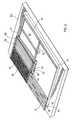
- the apparatus 20is fixed to an outer surface of the roof 100 of the building.
- the first and second sunlight-absorbent collector panels 22, 28, referred to herein as first and second collector panels 22, 28,are fixed to the outer surface of the roof 100.
- the roof 100is angled such that the first collector panel 22 is located at a position on the roof 100 that is below the position of the second collector panel 28.
- the first and second collector panels 22, 28are fixed to the outer surface of the roof 100 of the building in a metal framing structure 42 that includes a perimeter metal frame 44 and an interior longitudinal support bar 46.
- the longitudinal support bar 46separates the portion of the metal framing structure 42 containing the first collector panel 22 and the portion of the metal framing structure 42 containing the second collector panel 28.
- the metal framing structure 42 including the perimeter metal frame 44 and the longitudinal support bar 46is fixed to the roof 100 of the building using suitable fasteners.
- the metal framing structure 42also includes a backing 50 of metal panels that are secured against the roof 100 of the building, within the perimeter metal frame 44. Thus, the backing 50 is seated against the surface of the roof 100.
- the perimeter metal frame 44is sealed to the roof 100 using, for example, silicon caulking. Similarly, the metal panels of the backing 50 are sealed together and to the perimeter metal frame 44.
- the perimeter metal frame 44includes a track for receiving edges of the first and second collector panels 22, 28 therein.
- the longitudinal support bar 46also includes tracks for receiving edges of the first and second collector panels 22, 28 therein. It will be appreciated that the tracks are formed in the perimeter metal frame 44. Similarly, the tracks are formed in the longitudinal support bar 46.
- the first collector panelis secured within the metal framing structure 42 in the tracks of the perimeter metal frame 44 and the track on one side of the longitudinal support bar 46.
- the first panel 22includes a number of trapezoidal corrugations that define a plurality of similar and overlapping sub-panels 22a, 22b, 22c... etc.
- Each of the sub-panels or trapezoidal corrugations 22a, 22b, 22c... etc.includes a flat top portion 52, a pair of sloping side walls 54 and generally flat gutter walls 56.
- Each sloping side wall 54extends from a respective side of the flat top portion 52 and each gutter wall 56 extends from a respective side wall 54.
- the first collector panel 22is appropriately secured within the metal framing structure 42 such that each top portion 52 of the corrugations is generally parallel with and spaced from the backing 50. Clearly each top portion 52 is also generally parallel with the surface of the roof 100 of the building. Thus, the first collection air space 24 is left between the first panel 22 and the surface of the roof 100.
- the first panel 22includes the air inlet openings 26 distributed throughout the generally flat top portion 52, the sloping side walls 54 and the gutter walls 56.
- the air inlet openings 26provide openings for the first air collection space 24 for ambient air to travel from the exterior of the building into the first air collection space 24.
- the air inlet openings 26are generally uniformly distributed over the corrugated first collector panel 22 and are formed by rotary punching slits in the first collector panel 22 such that the gaps at the end of the slits provide the air inlet openings 26.
- the air inlet openings 26are small to aid in filtering air prior to entry into the solar heating apparatus 20.
- the first collector panelis coated on an exterior side thereof, with a selective coating.
- the selective coatingis a solar radiation absorbing coating for absorbing solar radiation with low infra-red heat radiation emission at temperatures occurring at the collector panel on a sunny day, to keep total energy losses low.
- the second collector panel 28is also secured within the metal framing structure 42, in the tracks of the perimeter metal frame 44 and one side of the track of the longitudinal support bar 46.
- the second collector panel 28includes a number of trapezoidal corrugations that define a plurality of similar and overlapping sub-panels 28a, 28b, 28c... etc.
- Each of the trapezoidal corrugations (sub-panels)includes a generally flat top portion 58, a pair of sloping side walls 60 and a generally flat gutter wall 62.
- Each sloping side wall 60extends from a respective side of the flat top portion 58 and each gutter wall 62 extends from a respective side wall 60.
- each top portion 58is not parallel with the backing 50 and the surface of the roof 100. Instead, each top portion 58 lies at an angle with the backing 50 and thus at an angle with the surface of the roof 100, such that the edge 64 of the second collector panel 28 that is closest to the first collector panel 22 is adjacent the backing 50 (with a side of the track disposed between the edge 64 of the second collector panel 28 and the surface of the roof 100), and the edge 66 of the second collector panel 28 that is distal the first collector panel 22 is spaced from the backing 50.
- the distance.between the second collector panel 28 and the backing 50increases with distance from the first collector panel 22.
- the depth of the second air collection space 30increases with distance from the first collector panel 22.
- the second collector panel 28includes second air inlet openings 32 that are distributed throughout the generally flat top portion 52, the sloping side walls 54 and the gutter walls 56 of the corrugations, as shown in Figure 1 B.
- the air inlet openings 32provide openings for the second air collection space 30.
- the second air inlet openings 32provide openings for air to travel from an intermediary flow chamber 36 and into the second air collection space 30.
- the intermediary air flow chamber 36is located between the first air collection space 24 and the second air collection space 30 with respect to the flow of air, as will be discussed further below.
- the air inlet openings 32are generally uniformly distributed over the second collector panel 28 and are formed by rotary punching slits in the second collector panel 28 such that the gaps at the end of the slits provide the air inlet openings 32.
- the second collector panel 28is also coated on the exterior side thereof with a solar radiation absorbing selective coating for absorbing solar radiation with low infra-red heat radiation emission at temperatures occurring at the collector panel on a sunny day.
- a glazingin the form of glazing panels 34, is located above and spaced from the second collector panel 28.
- the glazing panels 34are fixed to the upper half of the perimeter metal frame 44 and to the longitudinal support bar 46 using a glazing frame 68 that is fixed to the surface of the upper half of the perimeter metal frame 44 and the longitudinal support bar 46. It is not necessary for the glazing panels 34 to be sealed in an air-tight manner to the perimeter metal frame 44 and to the longitudinal support bar 46. A tight fit is sufficient as small air gaps are permissible.
- the space between the glazing panels 34 and the second collector panel 28is the intermediary air flow chamber 36, referred to above.
- the intermediary air flow chamber 36is in communication with the first air collection space 24 and with the second air collection space 30. Air flows into the intermediary air flow chamber 36 from the first air collection space 24 and air flows out of the intermediary air flow chamber 36 to the second air collection space 30.
- the longitudinal support bar 46is sized, shaped and located to support ends of the first and second collector panels 22, 28 and to support the edge of the glazing frame 68 which holds the glazing panels 34, while allowing the passage of air from the first air collection space 24 into the intermediary air flow chamber 36. In the present embodiment, this air flow is provided by gaps in the track in the longitudinal support bar 46, through which the air flows.
- An air duct 70is in communication with the second air collection space 30, extending through the backing 50 and passing through the roof 100 of the building.
- the air duct 70is connected to the second air collection space 30 by the outlet 38, for air to exit the second air collection space 30.
- the air outlet 38is located in a position that is distal to the longitudinal support beam 46, where the distance between the second collector panel 28 and the backing 50 is greatest.
- the air ductextends into the building to provide heated outside air to the interior of the building, through openings in the air duct 70.
- a fan housing 72is connected along the air duct 70 and includes the fan 40 for moving air from the second air collection space 30 into the interior of the building.
- Motorized dampers in the fan housing 72are adjustable to allow air from the interior of the building to be mixed with heated air coming from the second air collection space 30.
- the fan 40 within the fan housing 72is typically sized to meet ventilation requirements and to inhibit negative air pressure within the building.
- a positive air pressurecan be achieved by introducing the heated outside air into the building through the air duct 70. Interior air leaves the building through openings and cracks.
- the fan 40is a variable speed fan that is controlled by a controller dependent on the temperature of the incoming air. Thus, when the incoming air is below room temperature, the fan 40 runs at low speed. When the temperature of the incoming air is above room temperature, the fan speed increases to provide both ventilation air and space heating.
- the solar heating apparatus 20is located on the exterior of the building, on the roof 100. Ambient air enters the first air collection space 24 through the air inlet openings 26 of the first collector panel 22, where the air is initially heated. Thus, the first collector panel 22 acts as an unglazed solar collector.
- the second collector panel 28acts as a glazed solar collector.
- the airis withdrawn from the second air collection space 30 by the fan 40 and is expelled into the building through the duct 70, to provide heated ventilation air to the building.
- the solar heating apparatus 20 of the present embodimentincludes a first sunlight-absorbent collector panel 22 and a second sunlight-absorbent collector panel 28. Both the first and the second sunlight-absorbent collector panels 22, 28, are similar to the first and second sunlight-absorbent collector panels described above and therefore the first and second collector panels 22, 28 will not be further described herein. Also similar to the first described embodiment, glazing panels 34 are located above and spaced from the second collector panel 28. The glazing panels 34 are similar to the above-described glazing panels and are therefore not further described herein.
- the first collector panel 22is located on a wall 102 of the building. Rather than being located on the same wall, the second collector panel 28 is located on the roof 100 of the building.
- the metal framing structure 42includes an elbow at a midpoint thereof, where the longitudinal support bar 46 is located, along the line of intersection of the wall 102 and the roof 100 of the building.
- the remainder of the solar heating apparatus 20, including the flow of air therethrough,is similar to the solar heating apparatus 20 as described above and therefore is not further described herein.
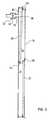
- the first collector panel 22is made up of a number of small overlapping sub-panels, each sub-panel being angled with respect to the surface of the roof 100, as shown. Each sub-panel is closest to the roof 100 of the building at the upper-most portion of the sub-panel. Thus, the space between the sub-panel and the surface of the roof increases from the uppermost to the lowermost portion of each sub-panel.
- the air inlet openings 32are located at the lowermost ends of the sub-panels, where the spacing between the sub-panel and the surface of the roof 100 is the greatest.
- the first collector panel 22is shown, it will be understood that the sub-panels as shown can also be used in a second collector panel 28 that includes a glazing 34 as described above.
- the solar heating apparatus 20is similar to the solar heating apparatus 20 shown in Figure 6 and described above. In the present embodiment, however, the solar heating apparatus 20 is mounted to a wall 102 of a building rather than the roof 102.
- the present inventionhas been described by way of examples. Modifications and variations to the above-described embodiments are possible.
- the density of air inlet opening in the first sunlight-absorbent collector panelcan increase with distance from the second sunlight-absorbent collector panel.
- the density of air openings 32 in the second sunlight-absorbent collector panelcan increase with distance from the air outlet.
- the size of the air inlet openings in the first sunlight-absorbent collector panelcan increase with distance from the second sunlight-absorbent collector panel.
- the size of the air inlet openings in the second sunlight-absorbent collector panelcan increase with distance from the air outlet.
- the trackswere formed in the longitudinal support bar 46.
- the tracksare fastened to the longitudinal support bar 46.
- a number of small track portions or clipsare attached to the longitudinal support bar 46 and spaced apart to allow air flow in between.
- trackscan be fastened to the perimeter metal frame 44, rather than being formed in the perimeter metal frame 44.
- the air inlet openings 26 and the air inlet openings 32are described as being formed by rotary punching slits in the first and second collector panels 22, 28, respectively, in an alternative embodiment, the air inlet openings 26 and the air inlet openings 32 are provided by holes punched in the first and second collector panels 22, 28, respectively.
- both the first and second collector panelscan be located on a wall of the building, rather than being located on a roof or on both a wall and a roof of the building.
- Thisprovides collector panels with corrugations that run in substantially vertical planes, as best shown in Figure 1.
Landscapes
- Engineering & Computer Science (AREA)
- Chemical & Material Sciences (AREA)
- Life Sciences & Earth Sciences (AREA)
- Sustainable Development (AREA)
- Sustainable Energy (AREA)
- Combustion & Propulsion (AREA)
- Mechanical Engineering (AREA)
- General Engineering & Computer Science (AREA)
- Thermal Sciences (AREA)
- Physics & Mathematics (AREA)
- Dispersion Chemistry (AREA)
- Roof Covering Using Slabs Or Stiff Sheets (AREA)
- Building Environments (AREA)
- Ventilation (AREA)
Abstract
Description
Claims (19)
- Apparatus (20) for use with a fan for supplying pre-heated ventilation air for a building, theapparatus comprising:a first sunlight-absorbent collector panel (22) on said building, the panel being exposedto ambient air and defining a first air collection space (24) between itself and said building, thefirst sunlight-absorbent collector panel having a plurality of air inlet openings (26) to allow theambient air to pass through the openings to the first air collection space;a second sunlight-absorbent collector (28) panel on said building, adjacent said firstsunlight-absorbent collector panel, the second sunlight-absorbent collector panel defining asecond air collection space (30) between itself and said building, the second sunlight-absorbentcollector panel having a plurality of air inlet openings (32) to allow air to pass through theopenings to the second air collection space;a glazing (34) covering said second sunlight-absorbent collector panel and defining anintermediary air flow chamber (36) between itself and said second sunlight-absorbent collectorpanel, said intermediary air flow chamber being in communication with said first air collectionspace to receive air therefrom, said air inlet openings in said second sunlight-absorbentcollector panel providing communication between said intermediary air flow chamber and saidsecond air collection space; andan air outlet (38) from said second air collection space for air flow therethrough forsupplying to said building after withdrawal of said pre-heated air by a fan.
- Apparatus as claimed in claim 1, further comprising a fan (40) in communication with said airoutlet (38) for moving air from said second air collection space (30) into said building, throughsaid air outlet.
- Apparatus as claimed in claim 2, wherein the fan (40) is able to be controlled at variablespeeds depending on temperature of the air withdrawn from the air outlet (38).
- Apparatus as claimed in claim 1, 2 or 3, wherein said first sunlight-absorbent collector panel(22) is corrugated and/or said second sunlight-absorbent collector panel (28) is corrugated.
- Apparatus as claimed in claim 4, wherein said first sunlight-absorbent collector panel (28) is corrugated with corrugations running in substantially vertical planes.
- Apparatus as claimed in any preceding claim, wherein the first sunlight-absorbent collectorpanel (22) comprises a plurality of substantially similar sub-panels and/or the second sunlight-absorbentcollector panel (28) comprises a plurality of substantially similar sub-panels.
- Apparatus as claimed in claim 6, wherein the first sunlight-absorbent collector panel (22)and/or the second sunlight-absorbent collector panel (28) is comprised of a plurality ofsubstantially similar and overlapping sub-panels.
- Apparatus as claimed in any preceding claim, wherein said plurality of air inlet openings (26)are comprised of slits and/or holes in the first sunlight-absorbent collector panel (22) and/or saidplurality of air inlet openings (32) are comprised of slits and/or holes in said second sunlight-absorbentcollector panel (28).
- Apparatus as claimed in any preceding claim, wherein said first and second sunlight-absorbentcollector panels (22, 28) are on a first surface of said building.
- Apparatus as claimed in claim 9, wherein said first sunlight-absorbent collector panel (22) ison a first surface of said building and said second (28) sunlight-absorbent collector panel is on asecond surface of said building, adjacent said first surface.
- Apparatus as claimed in any preceding claim, wherein said air inlet openings in said firstsunlight-absorbent collector panel are uniformly distributed on said panel.
- Apparatus as claimed in any preceding claim, wherein the density of said air inlet openings(26) in said first sunlight-absorbent collector panel (22) increases with distance from saidsecond sunlight-absorbent collector panel (28) and/or the density of said air inlet openings (32)in said second sunlight-absorbent collector panel increases with distance from said air outlet(38).
- Apparatus as claimed in any preceding claim, wherein the size of said air inlet openings(26) in said first sunlight-absorbent collector panel (22) increases with distance from saidsecond sunlight-absorbent collector panel (28) and/or the size of said air inlet openings (32) in said second sunlight-absorbent collector panel increases with distance from said air output (38).
- Apparatus as claimed in any preceding claim, wherein said first sunlight-absorbent collectorpanel (22) and/or said second sunlight-absorbent collector panel (28) includes a surface coatingon an exterior side thereof, the surface coating permitting high absorption of solar radiation andlow emission of far infra-red heat radiation.
- Apparatus as claimed in any preceding claim, wherein second sunlight-absorbent collectorpanel (28) is located above said first sunlight-absorbent collector panel (22).
- Apparatus as claimed in any preceding claim, wherein said first sunlight-absorbent collectorpanel (22) is located on a substantially vertical surface of said building.
- Apparatus as claimed in claim 16, wherein said second sunlight-absorbent collector panel(28) is located on said substantially vertical surface of said building or is located on a roof (100)of said building.
- A method of heating ventilation air for a building, comprising:providing apparatus (20) as claimed in any preceding claim;pre-heating outside air in the first air collection space (24), with solar heat from the firstsunlight-absorbent collector panel (22) and passing the pre-heated air into the intermediary flowchamber (36);heating the pre-heated air in the second air collection space (30) by passing the pre-heatedair from the intermediary flow chamber into the second air collection space, to provideheated air;withdrawing said heated air through the air outlet (38) from said second air collectionspace and expelling said air into said building.
- A method as claimed in claim 18, wherein pre-heating the outside air comprises removingheat from substantially an entire surface of said first sunlight-absorbent collector panel (22)and/or from substantially an entire surface of said second sunlight-absorbent collector panel(28).
Priority Applications (1)
| Application Number | Priority Date | Filing Date | Title |
|---|---|---|---|
| PL05252918TPL1596138T3 (en) | 2004-05-14 | 2005-05-12 | Method and apparatus for preheating ventilation air for a building |
Applications Claiming Priority (2)
| Application Number | Priority Date | Filing Date | Title |
|---|---|---|---|
| US10/846,112US7032588B2 (en) | 2004-05-14 | 2004-05-14 | Method and apparatus for preheating ventilation air for a building |
| US846112 | 2004-05-14 |
Publications (3)
| Publication Number | Publication Date |
|---|---|
| EP1596138A2true EP1596138A2 (en) | 2005-11-16 |
| EP1596138A3 EP1596138A3 (en) | 2007-05-23 |
| EP1596138B1 EP1596138B1 (en) | 2010-10-06 |
Family
ID=34941265
Family Applications (1)
| Application Number | Title | Priority Date | Filing Date |
|---|---|---|---|
| EP05252918AExpired - LifetimeEP1596138B1 (en) | 2004-05-14 | 2005-05-12 | Method and apparatus for preheating ventilation air for a building |
Country Status (11)
| Country | Link |
|---|---|
| US (1) | US7032588B2 (en) |
| EP (1) | EP1596138B1 (en) |
| JP (1) | JP4676808B2 (en) |
| CN (1) | CN100572974C (en) |
| AT (1) | ATE483944T1 (en) |
| CA (1) | CA2503395C (en) |
| DE (1) | DE602005023935D1 (en) |
| DK (1) | DK1596138T3 (en) |
| ES (1) | ES2356183T3 (en) |
| PL (1) | PL1596138T3 (en) |
| PT (1) | PT1596138E (en) |
Cited By (7)
| Publication number | Priority date | Publication date | Assignee | Title |
|---|---|---|---|---|
| DE102005058887A1 (en)* | 2005-12-09 | 2007-06-14 | Stys, Antoni Slawomir, Dipl.-Ing. | Solar heating system for building with blown airflow to heat rooms or warm water supply |
| FR2929379A1 (en)* | 2008-04-01 | 2009-10-02 | Opaly Soc Par Actions Simplifi | Hollow panel for fabricating wall of building, has fluid circulation channel extending between receiver and perforated receiver that is exposed to heat radiation and transform radiation by reflection, transmission and/or absorption |
| WO2009125159A3 (en)* | 2008-04-01 | 2010-08-19 | OPALY, Société par actions simplifiée | Method and device for trimming for facade or roof of a building |
| NL1036649C2 (en)* | 2009-03-02 | 2010-09-03 | Luijten Smeulders Architecten B V | BUILDING WITH ENERGY PRODUCTION PRODUCTS. |
| WO2010082908A3 (en)* | 2009-01-13 | 2011-01-06 | Gökser Maki̇na Sanayi̇ Ti̇c Ltd Şti̇ | Hybrid food drying system |
| EP2245380A4 (en)* | 2008-02-07 | 2014-01-01 | Soltech Energy Sweden Ab | Solar energy system |
| NL2011550C2 (en)* | 2013-10-03 | 2015-04-07 | Unda Maris Holding N V | WALL SYSTEM, FACADE PANEL THEREFORE, AND THE BUILDING PROVIDED FOR THIS. |
Families Citing this family (20)
| Publication number | Priority date | Publication date | Assignee | Title |
|---|---|---|---|---|
| US8827779B2 (en)* | 2006-05-18 | 2014-09-09 | Hollick Solar Systems Limited | Method and apparatus for cooling ventilation air for a building |
| US9574783B2 (en) | 2006-05-18 | 2017-02-21 | Hollick Solar Systems Limited | Method and apparatus for two stage cooling of ambient air |
| CA2559641C (en)* | 2006-09-13 | 2014-04-15 | Matrix Energy Inc. | Solar air heating system |
| US7677243B2 (en) | 2007-01-22 | 2010-03-16 | Wal-Mart Stores, Inc. | Solar heating system and architectural structure with a solar heating system |
| WO2008095502A2 (en)* | 2007-02-05 | 2008-08-14 | Paul Riis Arndt | Solar air heater for heating air flow |
| GB2486610B (en) | 2007-05-01 | 2012-08-01 | Kingspan Res & Dev Ltd | A method of manufacturing a composite insulating panel |
| US20100000520A1 (en)* | 2007-07-26 | 2010-01-07 | Vachon Christian | Perforated transparent glazing for heat recovery and solar air heating |
| EP2315980A4 (en)* | 2008-07-29 | 2015-05-06 | Syenergy Integrated Energy Solutions Inc | Curved transpired solar air heater and conduit |
| JP2010096457A (en)* | 2008-10-17 | 2010-04-30 | Nippon Light Metal Co Ltd | Air conditioning device |
| US8371073B2 (en)* | 2010-03-04 | 2013-02-12 | Michael Fuller Architects, Pc | Building with integrated natural systems |
| US8555872B2 (en) | 2011-03-04 | 2013-10-15 | John Allan Dolphin | Solar heater |
| CN102226586A (en)* | 2011-04-20 | 2011-10-26 | 上海福奥建筑科技有限公司 | Solar flat type heat collector and heat collection plate thereof |
| US20130118478A1 (en)* | 2011-11-11 | 2013-05-16 | Masdar Institute Of Science And Technology | Liquid-air transpired solar collectors |
| MX2015004266A (en)* | 2012-10-02 | 2015-11-13 | Grace Coulter | Solar air heating / cooling system. |
| EP2917426B1 (en)* | 2012-11-08 | 2023-06-07 | IIS Institute for Independent Studies Zürich GmbH | Building envelope and method for setting the temperature in a building |
| GB2526269B (en)* | 2014-05-16 | 2018-09-12 | Solar Frame Solutions Ltd | Solar-collector roofing assembly |
| GB2540384B (en)* | 2015-07-15 | 2020-04-29 | Energy Transitions Ltd | Transpired solar collector |
| CN105865042B (en)* | 2016-06-08 | 2017-12-05 | 日出东方太阳能股份有限公司 | A kind of solar air heater and heating means |
| CN110500774B (en)* | 2019-08-22 | 2021-06-04 | 沂源县源能热力有限公司 | Heating system with regulatory function |
| DK3988859T3 (en) | 2020-10-26 | 2023-02-06 | Almeco Gmbh | Deformable composite material for free standing solar energy absorbing collection panels with low loss of infrared radiation |
Family Cites Families (20)
| Publication number | Priority date | Publication date | Assignee | Title |
|---|---|---|---|---|
| JPS499492B1 (en)* | 1970-12-22 | 1974-03-05 | ||
| US4143815A (en)* | 1975-10-22 | 1979-03-13 | Energietechnik Gmbh | Heating apparatus |
| US4090494A (en)* | 1977-01-24 | 1978-05-23 | Southern Illinois University Foundation | Solar collector |
| US4478210A (en)* | 1979-04-16 | 1984-10-23 | Sieradski Leonard M | Solar heating system |
| FR2469674A1 (en)* | 1979-11-15 | 1981-05-22 | Omnium Fs Indl Cal | Solar energy trap with absorbent bodies of corrugated bitumastic board - to smooth variations in the rate of energy capture |
| FR2491599B1 (en)* | 1980-10-08 | 1986-04-04 | Olivier Gilbert | SOLAR COLLECTOR USING AIR AS A HEAT FLUID, AND ITS COMPONENTS |
| NL8102154A (en)* | 1981-05-01 | 1982-12-01 | Drs Hendrik Jan Dorrestijn | Roof mounted solar heat collector - has surface of flat porous highly light absorbent material |
| CA1196825A (en) | 1982-05-04 | 1985-11-19 | John C. Hollick | Method for preheating ventilation air in a building |
| FR2535444A1 (en)* | 1982-10-29 | 1984-05-04 | Dalmas Ets | Solar collector using air. |
| CA1283333C (en) | 1988-02-11 | 1991-04-23 | John Carl Hollick | Method and apparatus for preheating ventilation air for a building |
| US4899728A (en) | 1989-01-27 | 1990-02-13 | Solarwall International Limited | Method and apparatus for preheating ventilation air for a building |
| JPH04136660A (en)* | 1990-09-26 | 1992-05-11 | Yoshitomi Takeda | Solar system |
| JPH0781747B2 (en)* | 1993-03-31 | 1995-09-06 | 元旦ビューティ工業株式会社 | Solar heat collector |
| US5596981A (en)* | 1993-07-19 | 1997-01-28 | Soucy; Paul B. | Solar device and method for assembly |
| DE19505918A1 (en)* | 1995-02-21 | 1996-08-22 | Karlfried Cost | Solar collector for heating air |
| US5692491A (en)* | 1996-04-19 | 1997-12-02 | Midwest Research Institute | Unglazed transpired solar collector having a low thermal-conductance absorber |
| CA2230471C (en) | 1998-02-25 | 2001-09-11 | John Carl Hollick | Combined solar collector and photovoltaic cells |
| US5935343A (en) | 1998-03-13 | 1999-08-10 | Hollick; John Carl | Combined solar collector and photovoltaic cells |
| JP2002267227A (en)* | 2001-03-12 | 2002-09-18 | Ac Sogo Sekkei:Kk | Air supply device |
| JP2005024139A (en)* | 2003-06-30 | 2005-01-27 | Sekisui Chem Co Ltd | Solar wall system |
- 2004
- 2004-05-14USUS10/846,112patent/US7032588B2/ennot_activeExpired - Lifetime
- 2005
- 2005-04-01CACA002503395Apatent/CA2503395C/ennot_activeExpired - Lifetime
- 2005-04-21JPJP2005124287Apatent/JP4676808B2/ennot_activeExpired - Fee Related
- 2005-05-11CNCNB2005100725420Apatent/CN100572974C/ennot_activeExpired - Lifetime
- 2005-05-12EPEP05252918Apatent/EP1596138B1/ennot_activeExpired - Lifetime
- 2005-05-12ATAT05252918Tpatent/ATE483944T1/ennot_activeIP Right Cessation
- 2005-05-12PTPT05252918Tpatent/PT1596138E/enunknown
- 2005-05-12PLPL05252918Tpatent/PL1596138T3/enunknown
- 2005-05-12DKDK05252918.7Tpatent/DK1596138T3/enactive
- 2005-05-12DEDE602005023935Tpatent/DE602005023935D1/ennot_activeExpired - Lifetime
- 2005-05-12ESES05252918Tpatent/ES2356183T3/ennot_activeExpired - Lifetime
Cited By (7)
| Publication number | Priority date | Publication date | Assignee | Title |
|---|---|---|---|---|
| DE102005058887A1 (en)* | 2005-12-09 | 2007-06-14 | Stys, Antoni Slawomir, Dipl.-Ing. | Solar heating system for building with blown airflow to heat rooms or warm water supply |
| EP2245380A4 (en)* | 2008-02-07 | 2014-01-01 | Soltech Energy Sweden Ab | Solar energy system |
| FR2929379A1 (en)* | 2008-04-01 | 2009-10-02 | Opaly Soc Par Actions Simplifi | Hollow panel for fabricating wall of building, has fluid circulation channel extending between receiver and perforated receiver that is exposed to heat radiation and transform radiation by reflection, transmission and/or absorption |
| WO2009125159A3 (en)* | 2008-04-01 | 2010-08-19 | OPALY, Société par actions simplifiée | Method and device for trimming for facade or roof of a building |
| WO2010082908A3 (en)* | 2009-01-13 | 2011-01-06 | Gökser Maki̇na Sanayi̇ Ti̇c Ltd Şti̇ | Hybrid food drying system |
| NL1036649C2 (en)* | 2009-03-02 | 2010-09-03 | Luijten Smeulders Architecten B V | BUILDING WITH ENERGY PRODUCTION PRODUCTS. |
| NL2011550C2 (en)* | 2013-10-03 | 2015-04-07 | Unda Maris Holding N V | WALL SYSTEM, FACADE PANEL THEREFORE, AND THE BUILDING PROVIDED FOR THIS. |
Also Published As
| Publication number | Publication date |
|---|---|
| CA2503395A1 (en) | 2005-11-14 |
| US20050252507A1 (en) | 2005-11-17 |
| CA2503395C (en) | 2007-01-09 |
| DK1596138T3 (en) | 2011-01-31 |
| CN100572974C (en) | 2009-12-23 |
| JP2005326142A (en) | 2005-11-24 |
| ATE483944T1 (en) | 2010-10-15 |
| PT1596138E (en) | 2011-01-14 |
| DE602005023935D1 (en) | 2010-11-18 |
| US7032588B2 (en) | 2006-04-25 |
| EP1596138B1 (en) | 2010-10-06 |
| ES2356183T3 (en) | 2011-04-05 |
| EP1596138A3 (en) | 2007-05-23 |
| JP4676808B2 (en) | 2011-04-27 |
| PL1596138T3 (en) | 2011-03-31 |
| CN1760601A (en) | 2006-04-19 |
Similar Documents
| Publication | Publication Date | Title |
|---|---|---|
| EP1596138B1 (en) | Method and apparatus for preheating ventilation air for a building | |
| EP0380349B1 (en) | Improved method and apparatus for preheating ventilation air for a building | |
| HK1001925B (en) | Arrangement for preheating ventilation air for a building | |
| EP2021701B1 (en) | Method and apparatus for cooling ventilation air for a building | |
| JP2675385B2 (en) | Method and apparatus for preheating ventilation air | |
| CA2690650A1 (en) | Modular transpired solar air collector | |
| CA2559641C (en) | Solar air heating system | |
| US20210302030A1 (en) | Commercial building solar heating system | |
| CN101059279B (en) | Air type solar energy heat-collecting ventilation system | |
| JP2649906B2 (en) | Solar heat collector | |
| JP2846913B2 (en) | Building air preheating method and apparatus | |
| JPS58214745A (en) | solar heating equipment | |
| DE4334191A1 (en) | Building with air-conditioning system |
Legal Events
| Date | Code | Title | Description |
|---|---|---|---|
| PUAI | Public reference made under article 153(3) epc to a published international application that has entered the european phase | Free format text:ORIGINAL CODE: 0009012 | |
| AK | Designated contracting states | Kind code of ref document:A2 Designated state(s):AT BE BG CH CY CZ DE DK EE ES FI FR GB GR HU IE IS IT LI LT LU MC NL PL PT RO SE SI SK TR | |
| AX | Request for extension of the european patent | Extension state:AL BA HR LV MK YU | |
| PUAL | Search report despatched | Free format text:ORIGINAL CODE: 0009013 | |
| AK | Designated contracting states | Kind code of ref document:A3 Designated state(s):AT BE BG CH CY CZ DE DK EE ES FI FR GB GR HU IE IS IT LI LT LU MC NL PL PT RO SE SI SK TR | |
| AX | Request for extension of the european patent | Extension state:AL BA HR LV MK YU | |
| 17P | Request for examination filed | Effective date:20071119 | |
| AKX | Designation fees paid | Designated state(s):AT BE BG CH CY CZ DE DK EE ES FI FR GB GR HU IE IS IT LI LT LU MC NL PL PT RO SE SI SK TR | |
| GRAP | Despatch of communication of intention to grant a patent | Free format text:ORIGINAL CODE: EPIDOSNIGR1 | |
| GRAS | Grant fee paid | Free format text:ORIGINAL CODE: EPIDOSNIGR3 | |
| GRAA | (expected) grant | Free format text:ORIGINAL CODE: 0009210 | |
| AK | Designated contracting states | Kind code of ref document:B1 Designated state(s):AT BE BG CH CY CZ DE DK EE ES FI FR GB GR HU IE IS IT LI LT LU MC NL PL PT RO SE SI SK TR | |
| REG | Reference to a national code | Ref country code:GB Ref legal event code:FG4D | |
| REG | Reference to a national code | Ref country code:CH Ref legal event code:EP | |
| REG | Reference to a national code | Ref country code:IE Ref legal event code:FG4D | |
| REF | Corresponds to: | Ref document number:602005023935 Country of ref document:DE Date of ref document:20101118 Kind code of ref document:P | |
| REG | Reference to a national code | Ref country code:NL Ref legal event code:T3 | |
| REG | Reference to a national code | Ref country code:PT Ref legal event code:SC4A Free format text:AVAILABILITY OF NATIONAL TRANSLATION Effective date:20110104 | |
| REG | Reference to a national code | Ref country code:SE Ref legal event code:TRGR | |
| REG | Reference to a national code | Ref country code:DK Ref legal event code:T3 | |
| PG25 | Lapsed in a contracting state [announced via postgrant information from national office to epo] | Ref country code:SI Free format text:LAPSE BECAUSE OF FAILURE TO SUBMIT A TRANSLATION OF THE DESCRIPTION OR TO PAY THE FEE WITHIN THE PRESCRIBED TIME-LIMIT Effective date:20101006 | |
| LTIE | Lt: invalidation of european patent or patent extension | Effective date:20101006 | |
| REG | Reference to a national code | Ref country code:PL Ref legal event code:T3 | |
| REG | Reference to a national code | Ref country code:ES Ref legal event code:FG2A Ref document number:2356183 Country of ref document:ES Kind code of ref document:T3 Effective date:20110405 | |
| PG25 | Lapsed in a contracting state [announced via postgrant information from national office to epo] | Ref country code:LT Free format text:LAPSE BECAUSE OF FAILURE TO SUBMIT A TRANSLATION OF THE DESCRIPTION OR TO PAY THE FEE WITHIN THE PRESCRIBED TIME-LIMIT Effective date:20101006 | |
| PG25 | Lapsed in a contracting state [announced via postgrant information from national office to epo] | Ref country code:BG Free format text:LAPSE BECAUSE OF FAILURE TO SUBMIT A TRANSLATION OF THE DESCRIPTION OR TO PAY THE FEE WITHIN THE PRESCRIBED TIME-LIMIT Effective date:20110106 Ref country code:IS Free format text:LAPSE BECAUSE OF FAILURE TO SUBMIT A TRANSLATION OF THE DESCRIPTION OR TO PAY THE FEE WITHIN THE PRESCRIBED TIME-LIMIT Effective date:20110206 Ref country code:AT Free format text:LAPSE BECAUSE OF FAILURE TO SUBMIT A TRANSLATION OF THE DESCRIPTION OR TO PAY THE FEE WITHIN THE PRESCRIBED TIME-LIMIT Effective date:20101006 Ref country code:FI Free format text:LAPSE BECAUSE OF FAILURE TO SUBMIT A TRANSLATION OF THE DESCRIPTION OR TO PAY THE FEE WITHIN THE PRESCRIBED TIME-LIMIT Effective date:20101006 | |
| PG25 | Lapsed in a contracting state [announced via postgrant information from national office to epo] | Ref country code:GR Free format text:LAPSE BECAUSE OF FAILURE TO SUBMIT A TRANSLATION OF THE DESCRIPTION OR TO PAY THE FEE WITHIN THE PRESCRIBED TIME-LIMIT Effective date:20110107 | |
| PG25 | Lapsed in a contracting state [announced via postgrant information from national office to epo] | Ref country code:EE Free format text:LAPSE BECAUSE OF FAILURE TO SUBMIT A TRANSLATION OF THE DESCRIPTION OR TO PAY THE FEE WITHIN THE PRESCRIBED TIME-LIMIT Effective date:20101006 Ref country code:CZ Free format text:LAPSE BECAUSE OF FAILURE TO SUBMIT A TRANSLATION OF THE DESCRIPTION OR TO PAY THE FEE WITHIN THE PRESCRIBED TIME-LIMIT Effective date:20101006 | |
| PLBE | No opposition filed within time limit | Free format text:ORIGINAL CODE: 0009261 | |
| STAA | Information on the status of an ep patent application or granted ep patent | Free format text:STATUS: NO OPPOSITION FILED WITHIN TIME LIMIT | |
| PG25 | Lapsed in a contracting state [announced via postgrant information from national office to epo] | Ref country code:RO Free format text:LAPSE BECAUSE OF FAILURE TO SUBMIT A TRANSLATION OF THE DESCRIPTION OR TO PAY THE FEE WITHIN THE PRESCRIBED TIME-LIMIT Effective date:20101006 Ref country code:SK Free format text:LAPSE BECAUSE OF FAILURE TO SUBMIT A TRANSLATION OF THE DESCRIPTION OR TO PAY THE FEE WITHIN THE PRESCRIBED TIME-LIMIT Effective date:20101006 | |
| 26N | No opposition filed | Effective date:20110707 | |
| REG | Reference to a national code | Ref country code:HU Ref legal event code:AG4A Ref document number:E010838 Country of ref document:HU | |
| REG | Reference to a national code | Ref country code:DE Ref legal event code:R097 Ref document number:602005023935 Country of ref document:DE Effective date:20110707 | |
| PG25 | Lapsed in a contracting state [announced via postgrant information from national office to epo] | Ref country code:MC Free format text:LAPSE BECAUSE OF NON-PAYMENT OF DUE FEES Effective date:20110531 | |
| PG25 | Lapsed in a contracting state [announced via postgrant information from national office to epo] | Ref country code:LU Free format text:LAPSE BECAUSE OF NON-PAYMENT OF DUE FEES Effective date:20110512 Ref country code:CY Free format text:LAPSE BECAUSE OF FAILURE TO SUBMIT A TRANSLATION OF THE DESCRIPTION OR TO PAY THE FEE WITHIN THE PRESCRIBED TIME-LIMIT Effective date:20101006 | |
| PGFP | Annual fee paid to national office [announced via postgrant information from national office to epo] | Ref country code:HU Payment date:20130510 Year of fee payment:9 | |
| PGFP | Annual fee paid to national office [announced via postgrant information from national office to epo] | Ref country code:PT Payment date:20140505 Year of fee payment:10 | |
| PG25 | Lapsed in a contracting state [announced via postgrant information from national office to epo] | Ref country code:HU Free format text:LAPSE BECAUSE OF NON-PAYMENT OF DUE FEES Effective date:20140513 | |
| PGFP | Annual fee paid to national office [announced via postgrant information from national office to epo] | Ref country code:CH Payment date:20150527 Year of fee payment:11 | |
| REG | Reference to a national code | Ref country code:PT Ref legal event code:MM4A Free format text:LAPSE DUE TO NON-PAYMENT OF FEES Effective date:20151112 | |
| PG25 | Lapsed in a contracting state [announced via postgrant information from national office to epo] | Ref country code:PT Free format text:LAPSE BECAUSE OF NON-PAYMENT OF DUE FEES Effective date:20151112 | |
| REG | Reference to a national code | Ref country code:FR Ref legal event code:PLFP Year of fee payment:12 | |
| PGFP | Annual fee paid to national office [announced via postgrant information from national office to epo] | Ref country code:NL Payment date:20160516 Year of fee payment:12 | |
| PGFP | Annual fee paid to national office [announced via postgrant information from national office to epo] | Ref country code:BE Payment date:20160523 Year of fee payment:12 Ref country code:DK Payment date:20160523 Year of fee payment:12 | |
| REG | Reference to a national code | Ref country code:CH Ref legal event code:PL | |
| PG25 | Lapsed in a contracting state [announced via postgrant information from national office to epo] | Ref country code:CH Free format text:LAPSE BECAUSE OF NON-PAYMENT OF DUE FEES Effective date:20160531 Ref country code:LI Free format text:LAPSE BECAUSE OF NON-PAYMENT OF DUE FEES Effective date:20160531 | |
| REG | Reference to a national code | Ref country code:FR Ref legal event code:PLFP Year of fee payment:13 | |
| REG | Reference to a national code | Ref country code:DE Ref legal event code:R079 Ref document number:602005023935 Country of ref document:DE Free format text:PREVIOUS MAIN CLASS: F24J0002040000 Ipc:F24S0010000000 | |
| REG | Reference to a national code | Ref country code:DK Ref legal event code:EBP Effective date:20170531 | |
| REG | Reference to a national code | Ref country code:NL Ref legal event code:MM Effective date:20170601 | |
| PG25 | Lapsed in a contracting state [announced via postgrant information from national office to epo] | Ref country code:NL Free format text:LAPSE BECAUSE OF NON-PAYMENT OF DUE FEES Effective date:20170601 | |
| REG | Reference to a national code | Ref country code:BE Ref legal event code:MM Effective date:20170531 | |
| PG25 | Lapsed in a contracting state [announced via postgrant information from national office to epo] | Ref country code:DK Free format text:LAPSE BECAUSE OF NON-PAYMENT OF DUE FEES Effective date:20170531 | |
| REG | Reference to a national code | Ref country code:FR Ref legal event code:PLFP Year of fee payment:14 | |
| PG25 | Lapsed in a contracting state [announced via postgrant information from national office to epo] | Ref country code:BE Free format text:LAPSE BECAUSE OF NON-PAYMENT OF DUE FEES Effective date:20170531 | |
| REG | Reference to a national code | Ref country code:IE Ref legal event code:MM4A | |
| PG25 | Lapsed in a contracting state [announced via postgrant information from national office to epo] | Ref country code:IE Free format text:LAPSE BECAUSE OF NON-PAYMENT OF DUE FEES Effective date:20180512 | |
| REG | Reference to a national code | Ref country code:DE Ref legal event code:R119 Ref document number:602005023935 Country of ref document:DE | |
| PG25 | Lapsed in a contracting state [announced via postgrant information from national office to epo] | Ref country code:SE Free format text:LAPSE BECAUSE OF NON-PAYMENT OF DUE FEES Effective date:20200513 | |
| PG25 | Lapsed in a contracting state [announced via postgrant information from national office to epo] | Ref country code:DE Free format text:LAPSE BECAUSE OF NON-PAYMENT OF DUE FEES Effective date:20201201 | |
| PGFP | Annual fee paid to national office [announced via postgrant information from national office to epo] | Ref country code:IT Payment date:20220531 Year of fee payment:18 | |
| PG25 | Lapsed in a contracting state [announced via postgrant information from national office to epo] | Ref country code:PL Free format text:LAPSE BECAUSE OF NON-PAYMENT OF DUE FEES Effective date:20200512 | |
| PG25 | Lapsed in a contracting state [announced via postgrant information from national office to epo] | Ref country code:IT Free format text:LAPSE BECAUSE OF NON-PAYMENT OF DUE FEES Effective date:20230512 | |
| PGFP | Annual fee paid to national office [announced via postgrant information from national office to epo] | Ref country code:GB Payment date:20240430 Year of fee payment:20 | |
| PGFP | Annual fee paid to national office [announced via postgrant information from national office to epo] | Ref country code:ES Payment date:20240614 Year of fee payment:20 | |
| PGFP | Annual fee paid to national office [announced via postgrant information from national office to epo] | Ref country code:FR Payment date:20240522 Year of fee payment:20 | |
| PGFP | Annual fee paid to national office [announced via postgrant information from national office to epo] | Ref country code:TR Payment date:20240502 Year of fee payment:20 | |
| REG | Reference to a national code | Ref country code:ES Ref legal event code:FD2A Effective date:20250526 | |
| REG | Reference to a national code | Ref country code:GB Ref legal event code:PE20 Expiry date:20250511 | |
| PG25 | Lapsed in a contracting state [announced via postgrant information from national office to epo] | Ref country code:ES Free format text:LAPSE BECAUSE OF EXPIRATION OF PROTECTION Effective date:20250513 Ref country code:GB Free format text:LAPSE BECAUSE OF EXPIRATION OF PROTECTION Effective date:20250511 |