EP1595507A2 - Articulating ionizable gas coagulator - Google Patents
Articulating ionizable gas coagulatorDownload PDFInfo
- Publication number
- EP1595507A2 EP1595507A2EP05018087AEP05018087AEP1595507A2EP 1595507 A2EP1595507 A2EP 1595507A2EP 05018087 AEP05018087 AEP 05018087AEP 05018087 AEP05018087 AEP 05018087AEP 1595507 A2EP1595507 A2EP 1595507A2
- Authority
- EP
- European Patent Office
- Prior art keywords
- distal end
- tube
- sleeve
- electrosurgical apparatus
- tissue
- Prior art date
- Legal status (The legal status is an assumption and is not a legal conclusion. Google has not performed a legal analysis and makes no representation as to the accuracy of the status listed.)
- Granted
Links
- 230000001112coagulating effectEffects0.000claimsabstractdescription6
- 239000007789gasSubstances0.000claimsdescription52
- 229910000734martensiteInorganic materials0.000claimsdescription12
- 229910001285shape-memory alloyInorganic materials0.000claimsdescription10
- 229910001566austeniteInorganic materials0.000claimsdescription9
- XKRFYHLGVUSROY-UHFFFAOYSA-NArgonChemical compound[Ar]XKRFYHLGVUSROY-UHFFFAOYSA-N0.000claimsdescription6
- 229910052786argonInorganic materials0.000claimsdescription3
- 230000001105regulatory effectEffects0.000claimsdescription3
- 230000006399behaviorEffects0.000claimsdescription2
- 229910010293ceramic materialInorganic materials0.000claimsdescription2
- 241001354243CoronaSpecies0.000description17
- 230000000740bleeding effectEffects0.000description13
- 229910045601alloyInorganic materials0.000description9
- 239000000956alloySubstances0.000description9
- 230000015654memoryEffects0.000description8
- 230000015271coagulationEffects0.000description6
- 238000005345coagulationMethods0.000description6
- 239000000523sampleSubstances0.000description4
- 238000001356surgical procedureMethods0.000description4
- 230000009466transformationEffects0.000description4
- 241001631457CannulaSpecies0.000description3
- 206010051814EscharDiseases0.000description3
- 239000008280bloodSubstances0.000description3
- 210000004369bloodAnatomy0.000description3
- 230000001276controlling effectEffects0.000description3
- 230000005684electric fieldEffects0.000description3
- 231100000333escharToxicity0.000description3
- 230000006870functionEffects0.000description3
- 229910001000nickel titaniumInorganic materials0.000description3
- HLXZNVUGXRDIFK-UHFFFAOYSA-Nnickel titaniumChemical compound[Ti].[Ti].[Ti].[Ti].[Ti].[Ti].[Ti].[Ti].[Ti].[Ti].[Ti].[Ni].[Ni].[Ni].[Ni].[Ni].[Ni].[Ni].[Ni].[Ni].[Ni].[Ni].[Ni].[Ni].[Ni]HLXZNVUGXRDIFK-UHFFFAOYSA-N0.000description3
- 230000000451tissue damageEffects0.000description3
- 231100000827tissue damageToxicity0.000description3
- 230000008901benefitEffects0.000description2
- -1e.g.Inorganic materials0.000description2
- 230000003902lesionEffects0.000description2
- 238000000034methodMethods0.000description2
- 238000012986modificationMethods0.000description2
- 230000004048modificationEffects0.000description2
- 210000000056organAnatomy0.000description2
- RYGMFSIKBFXOCR-UHFFFAOYSA-NCopperChemical compound[Cu]RYGMFSIKBFXOCR-UHFFFAOYSA-N0.000description1
- 206010028980NeoplasmDiseases0.000description1
- HCHKCACWOHOZIP-UHFFFAOYSA-NZincChemical compound[Zn]HCHKCACWOHOZIP-UHFFFAOYSA-N0.000description1
- XAGFODPZIPBFFR-UHFFFAOYSA-NaluminiumChemical compound[Al]XAGFODPZIPBFFR-UHFFFAOYSA-N0.000description1
- 229910052782aluminiumInorganic materials0.000description1
- 238000013459approachMethods0.000description1
- 238000001574biopsyMethods0.000description1
- 230000036760body temperatureEffects0.000description1
- 230000008859changeEffects0.000description1
- 210000001072colonAnatomy0.000description1
- 229910052802copperInorganic materials0.000description1
- 239000010949copperSubstances0.000description1
- 239000013078crystalSubstances0.000description1
- 208000031513cystDiseases0.000description1
- 238000013461designMethods0.000description1
- 238000011161developmentMethods0.000description1
- 239000003989dielectric materialSubstances0.000description1
- 238000007599dischargingMethods0.000description1
- 230000009977dual effectEffects0.000description1
- 230000000694effectsEffects0.000description1
- 210000003238esophagusAnatomy0.000description1
- 239000012530fluidSubstances0.000description1
- 239000007943implantSubstances0.000description1
- 230000001939inductive effectEffects0.000description1
- 239000011261inert gasSubstances0.000description1
- 238000003780insertionMethods0.000description1
- 230000037431insertionEffects0.000description1
- 239000000463materialSubstances0.000description1
- 230000007246mechanismEffects0.000description1
- 230000003446memory effectEffects0.000description1
- 239000000203mixtureSubstances0.000description1
- 230000037361pathwayEffects0.000description1
- 238000012545processingMethods0.000description1
- 230000002441reversible effectEffects0.000description1
- 230000002269spontaneous effectEffects0.000description1
- 230000007704transitionEffects0.000description1
- 229910052725zincInorganic materials0.000description1
- 239000011701zincSubstances0.000description1
Images


Classifications
- A—HUMAN NECESSITIES
- A61—MEDICAL OR VETERINARY SCIENCE; HYGIENE
- A61B—DIAGNOSIS; SURGERY; IDENTIFICATION
- A61B18/00—Surgical instruments, devices or methods for transferring non-mechanical forms of energy to or from the body
- A61B18/04—Surgical instruments, devices or methods for transferring non-mechanical forms of energy to or from the body by heating
- A61B18/042—Surgical instruments, devices or methods for transferring non-mechanical forms of energy to or from the body by heating using additional gas becoming plasma
Definitions
- the present disclosurerelates to gas-enhanced electrosurgical instruments for coagulating tissue. More particularly, the present disclosure relates to an articulating, gas-enhanced electrosurgical apparatus for coagulating tissue.
- Endoscopic instruments for arresting blood loss and coagulating tissueare well known in the art.
- several prior art instrumentsemploy thermal coagulation (heated probes) to arrest bleeding.
- thermal coagulationheated probes
- surgeonscan have difficulty manipulating the instrument to coagulate, desiccate, fulgurate and/or cut tissue.
- the probemay adhere to the eschar during probe removal possibly causing repeat bleeding.
- Other instrumentsdirect high frequency electric current through the tissue to stop the bleeding. Again, eschar adherence may also be a problem with these instruments. In both types of instruments, the depth of the coagulation is difficult to control.
- U.S. Patent No. 5,720,745 to Farin et al.discloses a coagulation instrument which extends through a working channel of an endoscope and includes an electrode for ionizing a stream of ionizable gas exiting the distal end of the instrument at a rate of less than about 1 liter/minute.
- the purpose of discharging the gas at a very low flow rateis to effectively cloud the tissue area and create an ionizable gas "atmosphere" to gently coagulate the tissue.
- these longitudinally oriented instrumentsfire the ionised gas and the RF energy in an axial direction from their respective distal ends which, in the case of tubular tissue, would be parallel to the bleeding tissue.
- manipulating these instruments to focus the energy transversely or off-axis at the bleeding tissuemay be very difficult.
- the present disclosurerelates to an electrosurgical apparatus for coagulating tissue which includes an elongated flexible tube having a proximal end, a distal end a source for supplying pressurized ionizable gas to the proximal end of the tube.
- the apparatusin one embodiment includes a hollow sleeve made from a shape memory alloy, e.g., Nitinol and/or Tinel, which has a generally curved austenite state and displays stress-induced martensite behavior at norrnal body temperatures.
- the hollow sleeveis restrained in a deformed stress-induced martensite configuration within the tube wherein partial extension of a portion of the hollow sleeve from the tube transforms the portion from the deformed configuration to its generally curved austenite configuration such that the portion directs the gas transversely at the tissue.
- the surgical apparatusalso includes at least one active electrode and a source of high frequency electrical energy for ionizing the gas prior to the gas exiting the portion of the sleeve.
- the angle at which the gas is directed at the tissueis directly related to the distance the portion of the sleeve extends from the tube.
- the electrosurgical apparatusincludes a wire connected to the distal end of the tube.
- the wireis movable from a first generally relaxed position wherein the tube is disposed in generally rectilinear parallel fashion relative to the tissue to a second retracted position wherein the distal end of the tube flexes at an angle to direct the gas towards the tissue.
- the angle at which the gas is directed at the tissueis directly related to the amount of tension placed on the wire.
- Another embodimentincludes a corona electrode disposed proximate the distal end of the tube for inducing ignition of the plasma prior to emission.
- a wireis used to articulate the distal end of the tube and direct the gas at the tissue.
- the wireis connected to the corona electrode and electrically connects the corona electrode to a source of electrosurgical energy.
- a dielectric materialis preferably disposed between the corona electrode and the active electrode to prevent arcing between electrodes.
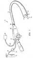
- an articulating tissue coagulatorgenerally identified by reference numeral 10 is shown extending through a working channel of an endoscope 12.
- the coagulator 10can be employed with a variety of different endoscopes such as those manufactured by Olympus, Pentax and Fujinon.
- endoscope 12includes a handpiece 26 having a proximal end 27 and a distal end 29.
- proximalas is traditional, will refer to the end of the apparatus which is closer to the user, while the term “distal” will refer to the end which is further from the user.
- the proximal end of the coagulator 10is mechanically coupled to a supply 18 of pressurized ionizable gas, e.g., inert gas, by way of hose 20 and electrically coupled to an electrosurgical generator 22 by way of cable 24 to supply a source of electrosurgical energy, e.g., high frequency coagulation current.
- a source of electrosurgical energye.g., high frequency coagulation current.
- the electrosurgical generator 22selectively controls the amount of electrosurgical energy transmitted to an electrode during a surgical procedure.
- the supply of pressurized ionizable gasselectively controls the rate of flow of gas.
- a pressure regulatordesignated by reference numeral 21, is preferably provided to regulate the fluid pressure.
- a long, flexible tubular member 13 having one or more of working channels 14 located thereinis mechanically coupled to the distal end 29 of the handpiece 26.
- at least one of the working channels 14is sufficiently dimensioned to receive the coagulator 10 of the present disclosure.
- Other working channels 14can be utilized to receive other surgical instruments and accessories such as graspers and biopsy forceps.
- a preferred embodiment of the coagulator 10includes an elongated, generally flexible catheter or tube 30 having a proximal end 32 which extends through a working channel 14 of the endoscope 12 and a distal end 34 which projects outwardly from the distal end 15 of tube 13.
- Ionizable gas 28, e.g., argonis supplied to the proximal end 32 of the coagulator 10 by a gas conduit (not shown) located inside tube 13.
- gas 28is supplied from source 18 to the coagulator 10 at a selectable, predetermined flow rate and flows generally within the tube 30 in the direction of the arrow towards the distal end 34 of tube 30.
- the flow rate of the gas 28is selectively adjustable and can easily be regulated depending upon a particular purpose or a particular surgical condition.
- Electrode 48produces an RF electric field, which ionizes the gas 28 in the region between the electrode and the tissue 50. Electrode 48 is connected by way of an electrical conduit (not shown) disposed within tubes 30 and 13 which is ultimately connected to electrosurgical generator 22. Preferably, the electrode 48 is ring or pin-type and is spaced from the distal end 34 such that the electrode 48 cannot come into contact with the tissue 50 during the surgical procedure.
- a return electrode or pad 17is positioned on the patient and is electrically coupled to the electrosurgical generator 22 to provide a return path for the electrosurgical current.
- a stream of gas plasma 46conducts the current to the tissue 50 while effectively scattering blood away from the treatment site allowing the tissue 50 to readily coagulate and arrest bleeding.
- a gas plasma 46is an ionized gas that is used in surgical procedures to conduct electrosurgical energy to a patient without electrode contact by providing a pathway of low electrical resistance. The electrosurgical energy will follow this path and can therefore be used to coagulate, desiccate, or fulgurate blood or tissue 50 of the patient.
- One of the advantages of this procedureis that no physical contact is required between an electrode 48 and the tissue 50 being treated.
- One advantage of having a directed flow of gas 28is that the plasma arc can be accurately focused and directed by the flow.
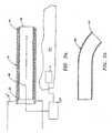
- one approach for manipulating and/or directing the plasma/ionized gas 46 emitting from the distal end 34 of the tube 30is to implant a hollow sleeve 40 having shape memory characteristics within the distal end 34 of the tube 30.
- the sleeve 40flexes and directs the ionized gas 46 towards the tissue 50.
- shape memory alloysare a family of alloys having anthropomorphic qualities of memory and trainability and are particularly well suited for use with medical instruments. SMAs have been applied to such items as actuators for control systems, steerable catheters and clamps. One of the most common SMAs is Nitinol which can retain shape memories for two different physical configurations and changes shape as a function of temperature. Recently, other SMAs have been developed based on copper, zinc and aluminum and have similar shape memory retaining features.
- SMAsundergo a crystalline phase transition upon applied temperature and/or stress variations.
- a particularly useful attribute of SMAsis that after it is deformed by temperature/stress, it can completely recover its original shape on being returned to the original temperature.
- the ability of an alloy to possess shape memoryis a result of the fact that the alloy undergoes a reversible transformation from an autstenite state to a martensite state with a change in temperature (or stress-induced condition). This transformation is referred to as a thermoelastic martensite transformation.
- thermoelastic martensite transformationoccurs over a temperature range which varies with the composition of the alloy, itself, and the type of thermal-mechanical processing by which it was manufactured.
- the temperature at which a shape is "memorized" by an SMAis a function of the temperature at which the martensite and austenite crystals form in that particular alloy.
- Nitinol alloyscan be fabricated so that the shape memory effect will occur over a wide range of temperatures, e.g., -270° to +100° Celsius.
- SMAsare also known to display stress-induced martensite (SIM) which occurs when the alloy is deformed from its original austenite state to a martensite state by subjecting the alloy to a stress condition.
- SIMstress-induced martensite
- hollow sleeve 40is generally bent or L-shaped when disposed in its original or austenite state (see Fig. 2B).
- sleeve 40is deformed, i.e., straightened, into a stress-induced martensite state enabling the user to more easily insert through the endoscope navigate the tube 30 through tight body cavities and passageways to access damaged tissue 50.
- the usercan easily direct the ionized gas 46 flowing through the tube 30 transversely (off-axis) at the tissue 50 by extending the sleeve 40 distally which causes the extended portion of the sleeve 40 to revert back to its original/austenite state (it is assumed that the temperature of use of the alloy allows spontaneous reversion when stress is removed).
- the usercan also control the angle s x of the ionized gas 46 being directed at the tissue 50 by controlling the distance "X" that the sleeve 40 extends from the tube 30.
- angle s x and distance "X"are directly related, i.e., as distance "X" increases angle s x increases.
- the distal end 41 of the sleeve 40by empowering the user to articulate, i.e., bend, the distal end 41 of the sleeve 40 at various angles s x will enable the operator to more effectively coagulate bleeding tissue 50 with more longitudinal-type lesions, i.e., tissue lesions which run parallel to the axial direction of endoscope 12, and without causing collateral tissue damage. It is also envisioned that by adjusting the angle s x of the distal end 41 of the sleeve 40, the angle with respect to the tissue surface or longitudinal axis of the tube at which the ionized gas 46 impinges can be selectively controlled.
- Figs. 4 and 5show another embodiment of an articulating coagulator 110 which includes an elongated tube 130 having a proximal end 132 and a distal end 134.
- tube 130is flexible at or proximate the distal end 134 of tube 130.
- Ionizable gas 28is supplied to the proximal end 132 of the coagulator 110 at a selectable, predetermined flow rate and flows generally within the tube 130 in the direction of the arrow towards the distal end 134 of tube 130.
- the flow rate of the gas 28is selectively adjustable and can easily be regulated depending upon a particular purpose or a particular surgical condition.
- electrode 48discharges an electrosurgical current which ionizes gas 28 prior to gas 28 emission.
- Coagulator 110also includes a pull wire 160 which is connected at one end proximate the distal end 134 of tube 130 such that retraction of wire 160 flexes tube 130.
- wire 160is disposed within the proximal end 132 of tube 130 and exits a port 136 disposed within tube 130 to attach to tube 130 at a point proximate distal end 134.
- Wire 160is movable from a first generally relaxed position wherein tube 30 is disposed in a generally rectilinear fashion relative to tissue 50 (see Fig. 4) to a second retracted or tensed position wherein the distal end 134 of tube 130 flexes towards tissue 50 (see Fig. 5).
- the usercan easily direct the ionized gas 46 flowing through the tube 130 transversely at tissue 50 by controlling the tensile force applied to wire 160 which, in turn, flexes the distal end 134 of tube 130 to a desired angle s x .
- Empowering the user to articulate, i.e., flex, the distal end 134 of the tube 130 at various angles s xwill enable the operator to more effectively target bleeding tissue 50 without causing collateral tissue damage.
- wire 160as a return electrode and couple wire 160 to electrosurgical generator 22.
- the portion of wire 160 disposed within tube 130is preferably insulated to avoid unintentional ignition and ionization of gas 28.
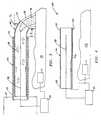
- Figs. 6-8show another embodiment which includes an articulating coagulator 210 having an elongated tube 230 with proximal and distal ends 232 and 234, respectively.
- tube 230is flexible at or proximate the distal end 234.
- Coagulator 210contains many of the same components and features of the Figs. 4 and 5 embodiment with the exception that a "corona ring" electrode is located at the distal end 234 of tube 230 and is used to initiate ionization of gas 28.
- Coronais a type of discharge which forms around an active electrode and can be used to increase the reliability of plasma ignition. Coronas are low current discharges and consume very little power and, therefore, do not affect the overall power delivered to the tissue. Coronas typically occur in highly non-uniform electric fields which are commonly generated between electrodes of greatly differing sizes.
- a corona electrodeis typically located proximate the active electrode 48 and is electrically connected to the return potential of the electrosurgical generator 22.
- a ring corona electrode 275is disposed at the distal end 234 of tube 230 in co-axial alignment with the active electrode 48.
- dielectric or insulating sleeve 270is disposed between the corona electrode 275 and active electrode 48 to prevent arcing between electrodes 275 and 48.
- dielectric sleeve 270is made from a ceramic material or other high temperature resistant material.
- coagulator 210also includes a wire 260 which is connected at one end proximate the distal end 234 of tube 230 such that retraction of the wire 260 flexes tube 230.
- wire 260is also connected to corona electrode 275 and performs a dual function: 1) to electrically connect corona electrode 275 to electrosurgical generator 22; and 2) to empower the user with the ability to selectively articulate the distal end 234 of tube 230 at varying angles s x to effectively coagulate bleeding tissue 50 in a manner similar to the manner described with respect to the Fig. 4 embodiment.
- the usercan easily direct gas plasma 46 exiting tube 230 transversely at tissue 50 by controlling the tensile force applied to wire 260 which, in turn, articulates distal end 234 to a desired angle s x and enables the user to more effectively coagulate or arrest bleeding tissue 50 without causing collateral tissue damage.
- a SMAstress-induced martensite
- a wireto articulate the distal end of the tube.
- a ring-like corona return electrodewith an SMA to induce plasma ignition.
- an electrode control mechanismto allow a user to selectively adjust the amount of current flowing through the electrodes during surgical conditions.
- argonas the ionizable gas for promulgating coagulation of the tissue
Landscapes
- Health & Medical Sciences (AREA)
- Surgery (AREA)
- Engineering & Computer Science (AREA)
- Life Sciences & Earth Sciences (AREA)
- Biomedical Technology (AREA)
- Molecular Biology (AREA)
- Nuclear Medicine, Radiotherapy & Molecular Imaging (AREA)
- Plasma & Fusion (AREA)
- Physics & Mathematics (AREA)
- Heart & Thoracic Surgery (AREA)
- Medical Informatics (AREA)
- Otolaryngology (AREA)
- Animal Behavior & Ethology (AREA)
- General Health & Medical Sciences (AREA)
- Public Health (AREA)
- Veterinary Medicine (AREA)
- Surgical Instruments (AREA)
- Endoscopes (AREA)
Abstract
Description
Claims (13)
- An electrosurgical apparatus for coagulating tissuethrough an endoscopic tube, said apparatus comprising:an elongated flexible tube having a proximal end and adistal end and defining a longitudinal axis, the tubeincluding a sleeve being selectively extendable therethrough;the sleeve including a distal end being movable from afirst position wherein the distal end is disposed in agenerally rectilinear fashion relative to the tissue to asecond position wherein the distal end directs pressurizedionizable gas flowing through the sleeve at an angle Sx withrespect to the longitudinal axis wherein the angle of thedistal end of the sleeve relative to the longitudinal axisprogressively changes proportionally to the distance that thedistal end of the sleeve extends from the tube; andat least one electrode mounted proximal to the distalend of the sleeve for ionizing pressurized ionizable gas.
- The electrosurgical apparatus according to claim 1,further comprising a regulator for regulating gas flowthrough the elongated tube.
- The electrosurgical apparatus according to claim 1 or 2,further comprising a supply of pressurized argon.
- The electrosurgical apparatus according to any one ofthe preceding claims, wherein the sleeve is a hollow shapememory alloy sleeve having a generally curved austeniteconfiguration and displaying stress-induced martensitebehavior, the hollow sleeve being at least partiallyrestrained in a deformed stress-induced martensiteconfiguration by the tube wherein extension of a portion of ahollow sleeve from the distal end of the tube transforms theunstrained portion from the deformed austenite configurationto a generally curved configuration such that the unstrainedportion can direct pressurized ionisable gas flowing through the tube at an angle Sx with respect to the longitudinalaxis.
- The electrosurgical apparatus according to claim 4,wherein the angle Sx relative to the longitudinal axisprogressively changes proportionally to the distance that aportion of the hollow sleeve extends from the distal end ofthe tube.
- The electrosurgical apparatus according to any one ofthe preceding claims, further comprising a wire connected tothe distal end of the tube, the wire being movable from afirst generally relaxed position wherein the distal end ofthe tube is disposed in a generally rectilinear fashionrelative to the tissue to a second retracted position whereinthe distal end of the tube directs pressurized ionizable gasflowing through the tube at an angle Sx with respect to thelongitudinal axis.
- The electrosurgical apparatus according to claim 6,wherein the angle relative to the longitudinal axisprogressively changes proportionally to the amount of tensionplaced on the wire.
- The electrosurgical apparatus according to claim 6 andclaim 7, wherein the wire also acts as a return electrode.
- The electrosurgical apparatus according to any one ofthe preceding claims, further comprising a corona electrodedisposed proximate the distal end of the tube.
- The electrosurgical apparatus according to claim 9,wherein the corona electrode is ring-shaped.
- The electrosurgical apparatus according to claim 9 or10, wherein the wire electrically connects the coronaelectrode to an electrical source.
- The electrosurgical apparatus according to any one ofclaims 9 to 11, further comprising a dielectric disposedbetween the at least one electrode and the corona electrode.
- The electrosurgical apparatus according to claim 12,wherein the dielectric is made from a ceramic material.
Applications Claiming Priority (3)
| Application Number | Priority Date | Filing Date | Title |
|---|---|---|---|
| US15774399P | 1999-10-05 | 1999-10-05 | |
| US157743P | 1999-10-05 | ||
| EP00121240AEP1090598B1 (en) | 1999-10-05 | 2000-10-02 | Deflectable ionizable-gas coagulator |
Related Parent Applications (1)
| Application Number | Title | Priority Date | Filing Date |
|---|---|---|---|
| EP00121240.6Division | 2000-10-02 |
Publications (3)
| Publication Number | Publication Date |
|---|---|
| EP1595507A2true EP1595507A2 (en) | 2005-11-16 |
| EP1595507A3 EP1595507A3 (en) | 2005-12-07 |
| EP1595507B1 EP1595507B1 (en) | 2012-03-21 |
Family
ID=35106566
Family Applications (2)
| Application Number | Title | Priority Date | Filing Date |
|---|---|---|---|
| EP05018087AExpired - LifetimeEP1595507B1 (en) | 1999-10-05 | 2000-10-02 | Articulating ionizable gas coagulator |
| EP05015625AExpired - LifetimeEP1602337B1 (en) | 1999-10-05 | 2000-10-02 | Articulatable ionizable gas coagulator |
Family Applications After (1)
| Application Number | Title | Priority Date | Filing Date |
|---|---|---|---|
| EP05015625AExpired - LifetimeEP1602337B1 (en) | 1999-10-05 | 2000-10-02 | Articulatable ionizable gas coagulator |
Country Status (1)
| Country | Link |
|---|---|
| EP (2) | EP1595507B1 (en) |
Cited By (34)
| Publication number | Priority date | Publication date | Assignee | Title |
|---|---|---|---|---|
| EP1764057A1 (en)* | 2005-09-19 | 2007-03-21 | Sherwood Services AG | Portable argon system |
| US7572255B2 (en) | 2004-02-03 | 2009-08-11 | Covidien Ag | Gas-enhanced surgical instrument |
| US7578818B2 (en) | 1999-10-05 | 2009-08-25 | Covidien Ag | Articulating ionizable gas coagulator |
| US7628787B2 (en) | 2004-02-03 | 2009-12-08 | Covidien Ag | Self contained, gas-enhanced surgical instrument |
| US7648503B2 (en) | 2006-03-08 | 2010-01-19 | Covidien Ag | Tissue coagulation method and device using inert gas |
| US7691102B2 (en) | 2006-03-03 | 2010-04-06 | Covidien Ag | Manifold for gas enhanced surgical instruments |
| US7833222B2 (en) | 2004-02-03 | 2010-11-16 | Covidien Ag | Gas-enhanced surgical instrument with pressure safety feature |
| US7927330B2 (en) | 1999-10-05 | 2011-04-19 | Covidien Ag | Multi-port side-fire coagulator |
| US8182480B2 (en) | 2008-08-19 | 2012-05-22 | Tyco Healthcare Group Lp | Insulated tube for suction coagulator |
| US8226642B2 (en) | 2008-08-14 | 2012-07-24 | Tyco Healthcare Group Lp | Surgical gas plasma ignition apparatus and method |
| US8226643B2 (en) | 2004-02-03 | 2012-07-24 | Covidien Ag | Gas-enhanced surgical instrument with pressure safety feature |
| US8286339B2 (en) | 2009-02-18 | 2012-10-16 | Tyco Healthcare Group Lp | Two piece tube for suction coagulator |
| US8328804B2 (en) | 2008-07-24 | 2012-12-11 | Covidien Lp | Suction coagulator |
| US8343090B2 (en) | 2009-08-26 | 2013-01-01 | Covidien Lp | Gas-enhanced surgical instrument with mechanism for cylinder puncture |
| EP2349044A4 (en)* | 2008-10-21 | 2013-05-15 | Hermes Innovations Llc | FABRIC ABLATION SYSTEMS |
| US8444641B2 (en) | 2009-02-18 | 2013-05-21 | Covidien Lp | Two piece tube for suction coagulator |
| US8454600B2 (en) | 2009-02-18 | 2013-06-04 | Covidien Lp | Two piece tube for suction coagulator |
| US8460291B2 (en) | 2009-02-18 | 2013-06-11 | Covidien Lp | Two piece tube for suction coagulator |
| US8690873B2 (en) | 2008-10-21 | 2014-04-08 | Hermes Innovations Llc | Endometrial ablation devices and systems |
| US8753341B2 (en) | 2009-06-19 | 2014-06-17 | Covidien Lp | Thermal barrier for suction coagulator |
| US8821486B2 (en) | 2009-11-13 | 2014-09-02 | Hermes Innovations, LLC | Tissue ablation systems and methods |
| US8998901B2 (en) | 2008-10-21 | 2015-04-07 | Hermes Innovations Llc | Endometrial ablation method |
| US9510897B2 (en) | 2010-11-05 | 2016-12-06 | Hermes Innovations Llc | RF-electrode surface and method of fabrication |
| US9649125B2 (en) | 2013-10-15 | 2017-05-16 | Hermes Innovations Llc | Laparoscopic device |
| US9662163B2 (en) | 2008-10-21 | 2017-05-30 | Hermes Innovations Llc | Endometrial ablation devices and systems |
| US9901394B2 (en) | 2013-04-04 | 2018-02-27 | Hermes Innovations Llc | Medical ablation system and method of making |
| EP3292830A1 (en)* | 2016-08-02 | 2018-03-14 | Covidien LP | System and method for catheter-based plasma coagulation |
| US10492856B2 (en) | 2015-01-26 | 2019-12-03 | Hermes Innovations Llc | Surgical fluid management system and method of use |
| US10675087B2 (en) | 2015-04-29 | 2020-06-09 | Cirrus Technologies Ltd | Medical ablation device and method of use |
| US11253311B2 (en) | 2016-04-22 | 2022-02-22 | RELIGN Corporation | Arthroscopic devices and methods |
| US11554214B2 (en) | 2019-06-26 | 2023-01-17 | Meditrina, Inc. | Fluid management system |
| US11576718B2 (en) | 2016-01-20 | 2023-02-14 | RELIGN Corporation | Arthroscopic devices and methods |
| US11766291B2 (en) | 2016-07-01 | 2023-09-26 | RELIGN Corporation | Arthroscopic devices and methods |
| US11896282B2 (en) | 2009-11-13 | 2024-02-13 | Hermes Innovations Llc | Tissue ablation systems and method |
Families Citing this family (1)
| Publication number | Priority date | Publication date | Assignee | Title |
|---|---|---|---|---|
| US9987073B2 (en) | 2013-11-19 | 2018-06-05 | Covidien Lp | Electrosurgical coagulation instrument including a suction pipe and a collapsible tip |
Citations (2)
| Publication number | Priority date | Publication date | Assignee | Title |
|---|---|---|---|---|
| US5207675A (en) | 1991-07-15 | 1993-05-04 | Jerome Canady | Surgical coagulation device |
| US5720745A (en) | 1992-11-24 | 1998-02-24 | Erbe Electromedizin Gmbh | Electrosurgical unit and method for achieving coagulation of biological tissue |
Family Cites Families (6)
| Publication number | Priority date | Publication date | Assignee | Title |
|---|---|---|---|---|
| US5231989A (en)* | 1991-02-15 | 1993-08-03 | Raychem Corporation | Steerable cannula |
| DE9117299U1 (en)* | 1991-11-27 | 2000-03-23 | Erbe Elektromedizin GmbH, 72072 Tübingen | Device for the coagulation of biological tissue |
| DE9117019U1 (en)* | 1991-11-27 | 1995-03-09 | Erbe Elektromedizin GmbH, 72072 Tübingen | Device for the coagulation of biological tissues |
| US5607435A (en)* | 1994-05-23 | 1997-03-04 | Memory Medical Systems, Inc. | Instrument for endoscopic-type procedures |
| US6213999B1 (en)* | 1995-03-07 | 2001-04-10 | Sherwood Services Ag | Surgical gas plasma ignition apparatus and method |
| DE69601352T2 (en)* | 1996-01-31 | 1999-08-26 | Jump Technologies Ltd. | Cold plasma coagulation device |
- 2000
- 2000-10-02EPEP05018087Apatent/EP1595507B1/ennot_activeExpired - Lifetime
- 2000-10-02EPEP05015625Apatent/EP1602337B1/ennot_activeExpired - Lifetime
Patent Citations (2)
| Publication number | Priority date | Publication date | Assignee | Title |
|---|---|---|---|---|
| US5207675A (en) | 1991-07-15 | 1993-05-04 | Jerome Canady | Surgical coagulation device |
| US5720745A (en) | 1992-11-24 | 1998-02-24 | Erbe Electromedizin Gmbh | Electrosurgical unit and method for achieving coagulation of biological tissue |
Cited By (52)
| Publication number | Priority date | Publication date | Assignee | Title |
|---|---|---|---|---|
| US7927330B2 (en) | 1999-10-05 | 2011-04-19 | Covidien Ag | Multi-port side-fire coagulator |
| US7955330B2 (en) | 1999-10-05 | 2011-06-07 | Covidien Ag | Multi-port side-fire coagulator |
| US7578818B2 (en) | 1999-10-05 | 2009-08-25 | Covidien Ag | Articulating ionizable gas coagulator |
| US8226644B2 (en) | 2004-02-03 | 2012-07-24 | Covidien Ag | Gas-enhanced surgical instrument |
| US8226643B2 (en) | 2004-02-03 | 2012-07-24 | Covidien Ag | Gas-enhanced surgical instrument with pressure safety feature |
| US8414578B2 (en) | 2004-02-03 | 2013-04-09 | Covidien Ag | Self contained, gas-enhanced surgical instrument |
| US7833222B2 (en) | 2004-02-03 | 2010-11-16 | Covidien Ag | Gas-enhanced surgical instrument with pressure safety feature |
| US7628787B2 (en) | 2004-02-03 | 2009-12-08 | Covidien Ag | Self contained, gas-enhanced surgical instrument |
| US7572255B2 (en) | 2004-02-03 | 2009-08-11 | Covidien Ag | Gas-enhanced surgical instrument |
| US8157795B2 (en) | 2004-02-03 | 2012-04-17 | Covidien Ag | Portable argon system |
| EP1764057A1 (en)* | 2005-09-19 | 2007-03-21 | Sherwood Services AG | Portable argon system |
| US7691102B2 (en) | 2006-03-03 | 2010-04-06 | Covidien Ag | Manifold for gas enhanced surgical instruments |
| US7648503B2 (en) | 2006-03-08 | 2010-01-19 | Covidien Ag | Tissue coagulation method and device using inert gas |
| US8808287B2 (en) | 2008-07-24 | 2014-08-19 | Covidien Lp | Suction coagulator |
| US9028490B2 (en) | 2008-07-24 | 2015-05-12 | Covidien Lp | Suction coagulator |
| US8328804B2 (en) | 2008-07-24 | 2012-12-11 | Covidien Lp | Suction coagulator |
| US8226642B2 (en) | 2008-08-14 | 2012-07-24 | Tyco Healthcare Group Lp | Surgical gas plasma ignition apparatus and method |
| US8182480B2 (en) | 2008-08-19 | 2012-05-22 | Tyco Healthcare Group Lp | Insulated tube for suction coagulator |
| US8998901B2 (en) | 2008-10-21 | 2015-04-07 | Hermes Innovations Llc | Endometrial ablation method |
| US10912606B2 (en) | 2008-10-21 | 2021-02-09 | Hermes Innovations Llc | Endometrial ablation method |
| US9662163B2 (en) | 2008-10-21 | 2017-05-30 | Hermes Innovations Llc | Endometrial ablation devices and systems |
| US11911086B2 (en) | 2008-10-21 | 2024-02-27 | Hermes Innovations Llc | Endometrial ablation devices and systems |
| US8690873B2 (en) | 2008-10-21 | 2014-04-08 | Hermes Innovations Llc | Endometrial ablation devices and systems |
| US10617461B2 (en) | 2008-10-21 | 2020-04-14 | Hermes Innovations Llc | Endometrial ablation devices and system |
| EP2349044A4 (en)* | 2008-10-21 | 2013-05-15 | Hermes Innovations Llc | FABRIC ABLATION SYSTEMS |
| US12070263B2 (en) | 2008-10-21 | 2024-08-27 | Hermes Innovations Llc | Endometrial ablation method |
| US8286339B2 (en) | 2009-02-18 | 2012-10-16 | Tyco Healthcare Group Lp | Two piece tube for suction coagulator |
| US8460291B2 (en) | 2009-02-18 | 2013-06-11 | Covidien Lp | Two piece tube for suction coagulator |
| US8454600B2 (en) | 2009-02-18 | 2013-06-04 | Covidien Lp | Two piece tube for suction coagulator |
| US8444641B2 (en) | 2009-02-18 | 2013-05-21 | Covidien Lp | Two piece tube for suction coagulator |
| US8753341B2 (en) | 2009-06-19 | 2014-06-17 | Covidien Lp | Thermal barrier for suction coagulator |
| US8343090B2 (en) | 2009-08-26 | 2013-01-01 | Covidien Lp | Gas-enhanced surgical instrument with mechanism for cylinder puncture |
| US9044219B2 (en) | 2009-08-26 | 2015-06-02 | Covidien Lp | Gas-enhanced surgical instrument with mechanism for cylinder puncture |
| US10213246B2 (en) | 2009-11-13 | 2019-02-26 | Hermes Innovations Llc | Tissue ablation systems and method |
| US11896282B2 (en) | 2009-11-13 | 2024-02-13 | Hermes Innovations Llc | Tissue ablation systems and method |
| US8821486B2 (en) | 2009-11-13 | 2014-09-02 | Hermes Innovations, LLC | Tissue ablation systems and methods |
| US9510897B2 (en) | 2010-11-05 | 2016-12-06 | Hermes Innovations Llc | RF-electrode surface and method of fabrication |
| US9901394B2 (en) | 2013-04-04 | 2018-02-27 | Hermes Innovations Llc | Medical ablation system and method of making |
| US11259787B2 (en) | 2013-10-15 | 2022-03-01 | Hermes Innovations Llc | Laparoscopic device |
| US10517578B2 (en) | 2013-10-15 | 2019-12-31 | Hermes Innovations Llc | Laparoscopic device |
| US9649125B2 (en) | 2013-10-15 | 2017-05-16 | Hermes Innovations Llc | Laparoscopic device |
| US10492856B2 (en) | 2015-01-26 | 2019-12-03 | Hermes Innovations Llc | Surgical fluid management system and method of use |
| US10675087B2 (en) | 2015-04-29 | 2020-06-09 | Cirrus Technologies Ltd | Medical ablation device and method of use |
| US11576718B2 (en) | 2016-01-20 | 2023-02-14 | RELIGN Corporation | Arthroscopic devices and methods |
| US12364534B2 (en) | 2016-01-20 | 2025-07-22 | RELIGN Corporation | Arthroscopic devices and methods |
| US11253311B2 (en) | 2016-04-22 | 2022-02-22 | RELIGN Corporation | Arthroscopic devices and methods |
| US11793563B2 (en) | 2016-04-22 | 2023-10-24 | RELIGN Corporation | Arthroscopic devices and methods |
| US11766291B2 (en) | 2016-07-01 | 2023-09-26 | RELIGN Corporation | Arthroscopic devices and methods |
| US11376058B2 (en) | 2016-08-02 | 2022-07-05 | Covidien Lp | System and method for catheter-based plasma coagulation |
| US10524849B2 (en) | 2016-08-02 | 2020-01-07 | Covidien Lp | System and method for catheter-based plasma coagulation |
| EP3292830A1 (en)* | 2016-08-02 | 2018-03-14 | Covidien LP | System and method for catheter-based plasma coagulation |
| US11554214B2 (en) | 2019-06-26 | 2023-01-17 | Meditrina, Inc. | Fluid management system |
Also Published As
| Publication number | Publication date |
|---|---|
| EP1595507B1 (en) | 2012-03-21 |
| EP1602337B1 (en) | 2007-12-19 |
| EP1602337A1 (en) | 2005-12-07 |
| EP1595507A3 (en) | 2005-12-07 |
Similar Documents
| Publication | Publication Date | Title |
|---|---|---|
| US6911029B2 (en) | Articulating ionizable gas coagulator | |
| EP1595507B1 (en) | Articulating ionizable gas coagulator | |
| US5207675A (en) | Surgical coagulation device | |
| US7648503B2 (en) | Tissue coagulation method and device using inert gas | |
| US7354435B2 (en) | Electrosurgical instrument | |
| EP3573556B1 (en) | Electrosurgical apparatus with flexible shaft | |
| EP3250141B1 (en) | Cold plasma electrosurgical apparatus with bent tip applicator | |
| JPH0663060A (en) | Electric surgical unit for achieving coagulation of biological tissue and method thereof | |
| US7611510B2 (en) | APC dual mode LEEP apparatus and method | |
| US20230093858A1 (en) | Electrosurgical apparatus with flexible shaft | |
| US20110077585A1 (en) | APC Dual Mode Theraputic Balloon Dilator | |
| AU2007203640B2 (en) | Articulating ionizable gas coagulator | |
| US20220151653A1 (en) | Cap for endoscope |
Legal Events
| Date | Code | Title | Description |
|---|---|---|---|
| PUAI | Public reference made under article 153(3) epc to a published international application that has entered the european phase | Free format text:ORIGINAL CODE: 0009012 | |
| PUAL | Search report despatched | Free format text:ORIGINAL CODE: 0009013 | |
| AC | Divisional application: reference to earlier application | Ref document number:1090598 Country of ref document:EP Kind code of ref document:P | |
| AK | Designated contracting states | Kind code of ref document:A2 Designated state(s):DE ES FR GB IE IT | |
| AK | Designated contracting states | Kind code of ref document:A3 Designated state(s):DE ES FR GB IE IT | |
| 17P | Request for examination filed | Effective date:20060531 | |
| 17Q | First examination report despatched | Effective date:20060710 | |
| AKX | Designation fees paid | Designated state(s):DE ES FR GB IE IT | |
| RAP1 | Party data changed (applicant data changed or rights of an application transferred) | Owner name:COVIDIEN AG | |
| GRAP | Despatch of communication of intention to grant a patent | Free format text:ORIGINAL CODE: EPIDOSNIGR1 | |
| GRAS | Grant fee paid | Free format text:ORIGINAL CODE: EPIDOSNIGR3 | |
| GRAA | (expected) grant | Free format text:ORIGINAL CODE: 0009210 | |
| AC | Divisional application: reference to earlier application | Ref document number:1090598 Country of ref document:EP Kind code of ref document:P | |
| AK | Designated contracting states | Kind code of ref document:B1 Designated state(s):DE ES FR GB IE IT | |
| REG | Reference to a national code | Ref country code:GB Ref legal event code:FG4D | |
| REG | Reference to a national code | Ref country code:IE Ref legal event code:FG4D | |
| REG | Reference to a national code | Ref country code:DE Ref legal event code:R096 Ref document number:60047019 Country of ref document:DE Effective date:20120516 | |
| PLBE | No opposition filed within time limit | Free format text:ORIGINAL CODE: 0009261 | |
| STAA | Information on the status of an ep patent application or granted ep patent | Free format text:STATUS: NO OPPOSITION FILED WITHIN TIME LIMIT | |
| 26N | No opposition filed | Effective date:20130102 | |
| PG25 | Lapsed in a contracting state [announced via postgrant information from national office to epo] | Ref country code:IT Free format text:LAPSE BECAUSE OF FAILURE TO SUBMIT A TRANSLATION OF THE DESCRIPTION OR TO PAY THE FEE WITHIN THE PRESCRIBED TIME-LIMIT Effective date:20120321 | |
| REG | Reference to a national code | Ref country code:DE Ref legal event code:R097 Ref document number:60047019 Country of ref document:DE Effective date:20130102 | |
| PG25 | Lapsed in a contracting state [announced via postgrant information from national office to epo] | Ref country code:ES Free format text:LAPSE BECAUSE OF FAILURE TO SUBMIT A TRANSLATION OF THE DESCRIPTION OR TO PAY THE FEE WITHIN THE PRESCRIBED TIME-LIMIT Effective date:20120702 | |
| REG | Reference to a national code | Ref country code:IE Ref legal event code:MM4A | |
| PG25 | Lapsed in a contracting state [announced via postgrant information from national office to epo] | Ref country code:IE Free format text:LAPSE BECAUSE OF NON-PAYMENT OF DUE FEES Effective date:20121002 | |
| REG | Reference to a national code | Ref country code:FR Ref legal event code:PLFP Year of fee payment:17 | |
| REG | Reference to a national code | Ref country code:FR Ref legal event code:PLFP Year of fee payment:18 | |
| REG | Reference to a national code | Ref country code:FR Ref legal event code:PLFP Year of fee payment:19 | |
| PGFP | Annual fee paid to national office [announced via postgrant information from national office to epo] | Ref country code:FR Payment date:20180920 Year of fee payment:19 | |
| PGFP | Annual fee paid to national office [announced via postgrant information from national office to epo] | Ref country code:GB Payment date:20180925 Year of fee payment:19 | |
| PGFP | Annual fee paid to national office [announced via postgrant information from national office to epo] | Ref country code:DE Payment date:20180819 Year of fee payment:19 | |
| REG | Reference to a national code | Ref country code:DE Ref legal event code:R119 Ref document number:60047019 Country of ref document:DE | |
| PG25 | Lapsed in a contracting state [announced via postgrant information from national office to epo] | Ref country code:DE Free format text:LAPSE BECAUSE OF NON-PAYMENT OF DUE FEES Effective date:20200501 | |
| GBPC | Gb: european patent ceased through non-payment of renewal fee | Effective date:20191002 | |
| PG25 | Lapsed in a contracting state [announced via postgrant information from national office to epo] | Ref country code:GB Free format text:LAPSE BECAUSE OF NON-PAYMENT OF DUE FEES Effective date:20191002 | |
| PG25 | Lapsed in a contracting state [announced via postgrant information from national office to epo] | Ref country code:FR Free format text:LAPSE BECAUSE OF NON-PAYMENT OF DUE FEES Effective date:20191031 |