EP1595489B1 - Fluid circulation pump with synchronous motor, equipped with heating means of the fluid, in particular for washing-machines - Google Patents
Fluid circulation pump with synchronous motor, equipped with heating means of the fluid, in particular for washing-machinesDownload PDFInfo
- Publication number
- EP1595489B1 EP1595489B1EP04425339AEP04425339AEP1595489B1EP 1595489 B1EP1595489 B1EP 1595489B1EP 04425339 AEP04425339 AEP 04425339AEP 04425339 AEP04425339 AEP 04425339AEP 1595489 B1EP1595489 B1EP 1595489B1
- Authority
- EP
- European Patent Office
- Prior art keywords
- fluid
- pump
- heating means
- rotor
- control unit
- Prior art date
- Legal status (The legal status is an assumption and is not a legal conclusion. Google has not performed a legal analysis and makes no representation as to the accuracy of the status listed.)
- Expired - Lifetime
Links
- 239000012530fluidSubstances0.000titleclaimsabstractdescription51
- 238000010438heat treatmentMethods0.000titleclaimsabstractdescription33
- 230000001360synchronised effectEffects0.000titleclaimsabstractdescription22
- 238000005406washingMethods0.000claimsabstractdescription15
- 230000004907fluxEffects0.000claimsabstractdescription11
- 230000005291magnetic effectEffects0.000claimsabstractdescription10
- 238000004804windingMethods0.000claimsabstractdescription7
- 230000005672electromagnetic fieldEffects0.000claimsabstractdescription3
- 230000006698inductionEffects0.000claimsdescription4
- 239000003302ferromagnetic materialSubstances0.000claimsdescription3
- 238000006073displacement reactionMethods0.000claimsdescription2
- 230000000694effectsEffects0.000claimsdescription2
- 230000001276controlling effectEffects0.000claims1
- 230000001105regulatory effectEffects0.000claims1
- 230000033228biological regulationEffects0.000description3
- 238000005086pumpingMethods0.000description3
- 230000008878couplingEffects0.000description2
- 238000010168coupling processMethods0.000description2
- 238000005859coupling reactionMethods0.000description2
- 238000010586diagramMethods0.000description2
- 238000004851dishwashingMethods0.000description2
- 230000003044adaptive effectEffects0.000description1
- 238000006243chemical reactionMethods0.000description1
- 239000004020conductorSubstances0.000description1
- 238000009434installationMethods0.000description1
- 230000007257malfunctionEffects0.000description1
- 230000004048modificationEffects0.000description1
- 238000012986modificationMethods0.000description1
- 239000012815thermoplastic materialSubstances0.000description1
- XLYOFNOQVPJJNP-UHFFFAOYSA-NwaterSubstancesOXLYOFNOQVPJJNP-UHFFFAOYSA-N0.000description1
Images


Classifications
- D—TEXTILES; PAPER
- D06—TREATMENT OF TEXTILES OR THE LIKE; LAUNDERING; FLEXIBLE MATERIALS NOT OTHERWISE PROVIDED FOR
- D06F—LAUNDERING, DRYING, IRONING, PRESSING OR FOLDING TEXTILE ARTICLES
- D06F39/00—Details of washing machines not specific to a single type of machines covered by groups D06F9/00 - D06F27/00
- D06F39/04—Heating arrangements
- D—TEXTILES; PAPER
- D06—TREATMENT OF TEXTILES OR THE LIKE; LAUNDERING; FLEXIBLE MATERIALS NOT OTHERWISE PROVIDED FOR
- D06F—LAUNDERING, DRYING, IRONING, PRESSING OR FOLDING TEXTILE ARTICLES
- D06F39/00—Details of washing machines not specific to a single type of machines covered by groups D06F9/00 - D06F27/00
- D06F39/08—Liquid supply or discharge arrangements
- A—HUMAN NECESSITIES
- A47—FURNITURE; DOMESTIC ARTICLES OR APPLIANCES; COFFEE MILLS; SPICE MILLS; SUCTION CLEANERS IN GENERAL
- A47L—DOMESTIC WASHING OR CLEANING; SUCTION CLEANERS IN GENERAL
- A47L15/00—Washing or rinsing machines for crockery or tableware
- A47L15/42—Details
- A47L15/4214—Water supply, recirculation or discharge arrangements; Devices therefor
- A47L15/4225—Arrangements or adaption of recirculation or discharge pumps
- A—HUMAN NECESSITIES
- A47—FURNITURE; DOMESTIC ARTICLES OR APPLIANCES; COFFEE MILLS; SPICE MILLS; SUCTION CLEANERS IN GENERAL
- A47L—DOMESTIC WASHING OR CLEANING; SUCTION CLEANERS IN GENERAL
- A47L15/00—Washing or rinsing machines for crockery or tableware
- A47L15/42—Details
- A47L15/4285—Water-heater arrangements
- D—TEXTILES; PAPER
- D06—TREATMENT OF TEXTILES OR THE LIKE; LAUNDERING; FLEXIBLE MATERIALS NOT OTHERWISE PROVIDED FOR
- D06F—LAUNDERING, DRYING, IRONING, PRESSING OR FOLDING TEXTILE ARTICLES
- D06F17/00—Washing machines having receptacles, stationary for washing purposes, wherein the washing action is effected solely by circulation or agitation of the washing liquid
- D06F17/02—Washing machines having receptacles, stationary for washing purposes, wherein the washing action is effected solely by circulation or agitation of the washing liquid by pumps
- D—TEXTILES; PAPER
- D06—TREATMENT OF TEXTILES OR THE LIKE; LAUNDERING; FLEXIBLE MATERIALS NOT OTHERWISE PROVIDED FOR
- D06F—LAUNDERING, DRYING, IRONING, PRESSING OR FOLDING TEXTILE ARTICLES
- D06F34/00—Details of control systems for washing machines, washer-dryers or laundry dryers
- D06F34/14—Arrangements for detecting or measuring specific parameters
- D06F34/22—Condition of the washing liquid, e.g. turbidity
- D06F34/24—Liquid temperature
- D—TEXTILES; PAPER
- D06—TREATMENT OF TEXTILES OR THE LIKE; LAUNDERING; FLEXIBLE MATERIALS NOT OTHERWISE PROVIDED FOR
- D06F—LAUNDERING, DRYING, IRONING, PRESSING OR FOLDING TEXTILE ARTICLES
- D06F39/00—Details of washing machines not specific to a single type of machines covered by groups D06F9/00 - D06F27/00
- D06F39/08—Liquid supply or discharge arrangements
- D06F39/083—Liquid discharge or recirculation arrangements
- D06F39/085—Arrangements or adaptations of pumps
- F—MECHANICAL ENGINEERING; LIGHTING; HEATING; WEAPONS; BLASTING
- F04—POSITIVE - DISPLACEMENT MACHINES FOR LIQUIDS; PUMPS FOR LIQUIDS OR ELASTIC FLUIDS
- F04D—NON-POSITIVE-DISPLACEMENT PUMPS
- F04D15/00—Control, e.g. regulation, of pumps, pumping installations or systems
- F04D15/0066—Control, e.g. regulation, of pumps, pumping installations or systems by changing the speed, e.g. of the driving engine
- F—MECHANICAL ENGINEERING; LIGHTING; HEATING; WEAPONS; BLASTING
- F04—POSITIVE - DISPLACEMENT MACHINES FOR LIQUIDS; PUMPS FOR LIQUIDS OR ELASTIC FLUIDS
- F04D—NON-POSITIVE-DISPLACEMENT PUMPS
- F04D15/00—Control, e.g. regulation, of pumps, pumping installations or systems
- F04D15/0088—Testing machines
- F—MECHANICAL ENGINEERING; LIGHTING; HEATING; WEAPONS; BLASTING
- F04—POSITIVE - DISPLACEMENT MACHINES FOR LIQUIDS; PUMPS FOR LIQUIDS OR ELASTIC FLUIDS
- F04D—NON-POSITIVE-DISPLACEMENT PUMPS
- F04D29/00—Details, component parts, or accessories
- F04D29/40—Casings; Connections of working fluid
- F04D29/42—Casings; Connections of working fluid for radial or helico-centrifugal pumps
- F04D29/426—Casings; Connections of working fluid for radial or helico-centrifugal pumps especially adapted for liquid pumps
- F—MECHANICAL ENGINEERING; LIGHTING; HEATING; WEAPONS; BLASTING
- F04—POSITIVE - DISPLACEMENT MACHINES FOR LIQUIDS; PUMPS FOR LIQUIDS OR ELASTIC FLUIDS
- F04D—NON-POSITIVE-DISPLACEMENT PUMPS
- F04D29/00—Details, component parts, or accessories
- F04D29/58—Cooling; Heating; Diminishing heat transfer
- F04D29/586—Cooling; Heating; Diminishing heat transfer specially adapted for liquid pumps
- F04D29/588—Cooling; Heating; Diminishing heat transfer specially adapted for liquid pumps cooling or heating the machine
- D—TEXTILES; PAPER
- D06—TREATMENT OF TEXTILES OR THE LIKE; LAUNDERING; FLEXIBLE MATERIALS NOT OTHERWISE PROVIDED FOR
- D06F—LAUNDERING, DRYING, IRONING, PRESSING OR FOLDING TEXTILE ARTICLES
- D06F2105/00—Systems or parameters controlled or affected by the control systems of washing machines, washer-dryers or laundry dryers
- D06F2105/10—Temperature of washing liquids; Heating means therefor
Definitions
- the present inventionrelates to a washing fluid circulation pump driven by a synchronous electric motor, equipped with fluid heating means and particularly, but not exclusively, of the type being incorporated in washing machines and dish-washing machines for civil and industrial use.
- the inventionrelates to a fluid circulation pump comprising a permanent-magnet synchronous electric driving motor, housed in a pump body being closed by a cover housing the heating means.
- the inventionrelates particularly, but not exclusively, to a fluid circulation pump for dish-washing machines and the following description is made with reference to this field of application for convenience of illustration only.
- the washing fluid of washing machinesis drawn by a source, for example the pipeline network, and it undergoes a heating step.
- This fluidflows in the machine by means of a circulation pump through a delivery opening in a machine washing tank.
- the fluidcan be advantageously heated at a temperature being predetermined by a washing program.
- the European Patent application no. 1 334 689 by Fischer & Paykeldiscloses a dishwasher including a wash chamber equipped by a wash pump which receives water from a heating chamber located in the bottom of the wash chamber. In this solution the heating means are located in the heating chamber.
- the United States Patent no. 3,051,182 by G.M. Gibsonshows a circulation pump equipped with an heating element being incorporated in the impeller chamber, i.e. an element plunging in the fluid itself. More particularly, the heating element arc-wraps the chamber housing the impeller and it is essentially arranged along the fluid recycle path from the pump to the washing tank.
- heating meanscan be indifferently arranged inside or outside the pump body in correspondence with the pump pumping area.
- heating meansgenerally composed of resistances, are driven by one or more temperature or fluid pressure sensors
- topologies of resistance generally used to this purposehave a very long hysteresis time and, without thermal exchange, i.e. without any fluid within the body pump, they risk burning irreparably damaging the pump itself.
- the resistance turn on and offdepends on the good operation of temperature and/or pressure sensors.
- manostatsIn the case of pressure sensors, manostats are used, which, plunging in the fluid, must be inserted watertight.
- the technical problem underlying the present inventionis to provide a synchronous-motor fluid circulation pump, particularly suitable for the installation in washing machines, having such structural and functional features as to allow an effective control and drive of the fluid heating means overcoming the drawbacks cited with reference to prior art solutions.
- Another aim of the inventionis to realise a pump being capable to achieve said features at very reduced costs and exploiting the scale economies being typical of the products realised on a very large scale.
- the solution idea underlying the present inventionis to detect the fluid temperature in the pump and the fluid flow rate, avoiding the use of temperature and/or pressure sensors, and to cut the resistance electric supply off once predetermined critical values are reached.
- a washing fluid circulation pump in washing machines and the likeis globally and schematically shown with 10.
- the pump 10realised according to the present invention, is equipped with fluid heating means 40 and it is driven by a synchronous electric motor 14.
- the pump 10can be realised in two modes, both falling however in the scope of the present invention.
- a first modeprovides a pump structure with an electronic control of the electric supply at the motor windings in order to regulate the motor operation in the start-up step and in load variation situations; while a second mode provides a more simplified structure with coupling joints between the rotor and the impeller in order to favour the motor start-up step.
- a control circuitcomprising a power regulation circuit portion and a current regulation circuit portion is associated to the pump permanent-magnet synchronous electric motor.
- the kind of control adopted for the power regulation circuitis of the adaptive type, since the voltage applied to the synchronous electric motor windings is adapted to the load and line voltage conditions in order to reach the lowest absorbed power value, for example as described in the European patent application no. 03425409.4 by the same Applicant.
- the difference between the two pump embodimentsis not very relevant but because in the one case the pump is already equipped with an electronic control circuit, while in the other case the pump must be equipped with a control unit, for example as shown in figure 5 and describe hereafter.
- the synchronous motor 14, seen in figure 3, and partially in figure 4,comprises a stator 15 being centrally crossed by a shell housing the rotor 18.
- the rotor 18is a permanent-magnet one and it is insulated tight with respect to the stator 15 by said shell.
- Said shellis closed at the top by a volute 17 housing an impeller 16.
- the rotor 18is rotation-driven by the electromagnetic field generated by the stator 15, equipped with pole shoes 20 with the relevant windings, and it is integral with a x-x-axis rotation shaft.
- the synchronous motor 14comprises a magnetic flux sensor 22 of the rotor 18, for example an analogue Hall sensor, arranged on the stator 15 close to the rotor 18.
- the rotation shaft of the synchronous motor 14is coupled at the top to the impeller 16 by means of a known kinematic coupling, for example as described in the European patent no. 0 983 630 by the same Applicant.
- the impeller 16is coaxial to the axis x-x, being arranged in alignment with an end of the rotation shaft.
- the synchronous motor 14comprises a protection pump body 13, preferably of thermoplastic material.
- the pump body 13has sideways to the volute 17, and in correspondence with the impeller 16, a delivery opening 30 communicating with the impeller 16 housing chamber.
- This delivery opening 30has preferably an orthogonal axis to the axis x-x and it is arranged tangentially to the volute 17 of the impeller 16.
- the pump body 13has also, above the impeller 16, a cover 19 comprising a suction opening 31 wherefrom the fluid pumped by the impeller 16 is sucked through the delivery opening 30.
- the suction opening 31has preferably an axis being parallel to the axis x-x.
- the cover 19houses the heating means 40.
- These heating means 40comprise a ring-shaped, substantially C-shaped, resistance 41, being coaxial to the axis x-x and arranged near the periphery of the cover 19.
- the resistanceis wrapped by a conductive material and in the case indicated in the figure it has a trapezoid cross section, with the larger base arranged near the cover 19 in order to allow a higher contact surface with the cover 19.
- the resistance 41has at the two terminals two clamps 42a and 42b for the electric connection to the power supply.
- the fluid circulation pump 10comprises a control unit 24 of the type shown in the block diagram of figure 5 which allows the synchronous electric motor 14 to be monitored.
- the control unit 24is meant to be incorporated and/or integrated in the pump control circuit.
- the control circuiteventually already existing in order to regulate the electric supply at the motor windings must be equipped with the componentry described hereafter for realising the present invention.
- a memory portionis associated to the control unit 24 wherein correlation experimental data between the values of an operating variable of the synchronous motor 14 of the pump 10 and the values corresponding to the pump 10 flow rate are stored.
- An operating variable of the synchronous motor 14, during the steady operation thereof,is the measure of the load or lag angle ⁇ representing the phase displacement between the voltage applied across the synchronous motor 14 and the counter electromotive force caused by the sum of the effects of the stator 15 flux and of the flux induced by the rotor 18 permanent magnet rotation.
- the control unit 24receives at the input a signal from the analogue Hall sensor 22, relating to the reading of the polarity inversion of the rotor 18 magnet, moreover it receives a network clock signal 25 and a signal being proportional to the effective value of the network voltage 26.
- the control unit 24through a predetermined correlation, in the absence of corrective factors, defines the value of the load or lag angle ⁇ and a corresponding flow rate value 50.
- the rotor 18plunges in the operating fluid, and in this case the magnet temperature corresponds to the operating fluid one.
- This dependenceis due to the fact that the ferromagnetic material composing the rotor 18 has a residual magnetic induction B R varying according to the fluid temperature.
- the analogue Hall sensor 22is capable to provide a sinusoidal signal with an amplitude being proportional to the residual induction B R of the ferromagnetic material composing the rotor 18 and thus to provide the fluid temperature during the passage in the pump 10.
- the control unit 24comprises means 35 allowing the fluid temperature to be drawn from the amplitude of the sinusoidal signal provided by the analogue Hall sensor 22.
- control unit 24comprises means 36 to compare the drawn fluid temperature value with a threshold reference value. Upon reaching this threshold reference value the means 36 allow a control signal 47 to be provided at the control unit output for cutting the electric power supply of the heating means 40 off.
- the means 36can conveniently comprise a comparator having at the input the threshold reference value, eventually inserted in the control unit 24 memory, and the signal coming from the means 35. Upon exceeding the threshold reference value the comparator outputs a digital signal 47 which, for example by means of a traditional D/A conversion, allows the operation on a power switch 43 inserted on the power supply line to the resistance 41, interrupting the supply itself. Obviously, nothing prevents the digital signal outputted from the comparator from being directly used to drive an inserted discrete or integrated electronic component as a switch on the power supply line towards the resistance.
- the signal 47 outputted from the control unit 24can be also used by the washing machine producer in the hypothesis that heating means are driven by a washing programmer and not by means of switching devices mounted on board of the pump 10.
- the pump 10can be structured with a power switch 43 in order to independently cut the power supply of the heating means 40 associated thereto off, or it can simply provide, on an output of the control unit 24, and thus of the electronic circuit incorporating it, an analogue or digital electric signal 47 to be used in order to cut the power supply to the heating means 40 off by means of an external control unit, for example a washing machine programmer.
- a power switch 43in order to independently cut the power supply of the heating means 40 associated thereto off, or it can simply provide, on an output of the control unit 24, and thus of the electronic circuit incorporating it, an analogue or digital electric signal 47 to be used in order to cut the power supply to the heating means 40 off by means of an external control unit, for example a washing machine programmer.
- control unit 24 of the pump 10can detect the fluid within the pump 10 through the value outputted from the control unit 24, i.e. the pump 10 flow rate.
- the control unit 24can compare the drawn value of the flow rate 50 with a threshold reference value, which in this case is conveniently a value near to zero. Upon reaching this threshold reference value, and thus without any fluid, the means 36 allow the electric power supply to the resistance 41 to be cut off.
- the main advantage reached by the present inventionis to allow the fluid heating means to be controlled in a simple and reliable way, avoiding the use of temperature and pressure sensors.
Landscapes
- Engineering & Computer Science (AREA)
- Textile Engineering (AREA)
- General Engineering & Computer Science (AREA)
- Mechanical Engineering (AREA)
- Thermal Sciences (AREA)
- Physics & Mathematics (AREA)
- Water Supply & Treatment (AREA)
- Control Of Positive-Displacement Pumps (AREA)
- Control Of Non-Positive-Displacement Pumps (AREA)
- Control Of Washing Machine And Dryer (AREA)
- Detail Structures Of Washing Machines And Dryers (AREA)
- Structures Of Non-Positive Displacement Pumps (AREA)
- Control Of Motors That Do Not Use Commutators (AREA)
- Cleaning By Liquid Or Steam (AREA)
Abstract
Description
- In its more general aspect the present invention relates to a washing fluid circulation pump driven by a synchronous electric motor, equipped with fluid heating means and particularly, but not exclusively, of the type being incorporated in washing machines and dish-washing machines for civil and industrial use.
- In particular, the invention relates to a fluid circulation pump comprising a permanent-magnet synchronous electric driving motor, housed in a pump body being closed by a cover housing the heating means.
- The invention relates particularly, but not exclusively, to a fluid circulation pump for dish-washing machines and the following description is made with reference to this field of application for convenience of illustration only.
- As it is well known to the skilled in the art, the washing fluid of washing machines is drawn by a source, for example the pipeline network, and it undergoes a heating step. This fluid flows in the machine by means of a circulation pump through a delivery opening in a machine washing tank.
- During this step, the fluid can be advantageously heated at a temperature being predetermined by a washing program.
- There are several prior art solutions to provide for the fluid heating during the step wherein the circulation provides the passage into the pump.
- The
European Patent application no. 1 334 689 by Fischer & Paykel discloses a dishwasher including a wash chamber equipped by a wash pump which receives water from a heating chamber located in the bottom of the wash chamber. In this solution the heating means are located in the heating chamber. - For example, the
United States Patent no. 3,051,182 by G.M. Gibson shows a circulation pump equipped with an heating element being incorporated in the impeller chamber, i.e. an element plunging in the fluid itself. More particularly, the heating element arc-wraps the chamber housing the impeller and it is essentially arranged along the fluid recycle path from the pump to the washing tank. - Another solution is described in the
German patent no. DE 3627732 by E.G.O. Italiana Spa showing a circulation pump for fluids to be heated comprising an heating area and a pumping area. The heating area comprises heating means arranged for most of the length thereof in the pumping area, thus benefiting from the fluid turbulent flow. - In the several solutions being provided in this patent, particularly figure 4 to figure 6, heating means can be indifferently arranged inside or outside the pump body in correspondence with the pump pumping area.
- A totally similar solution is also described in the
international patent application no. WO 00/28878 - All the indicated solutions, although advantageous under several aspects, have the drawback that heating means, generally composed of resistances, are driven by one or more temperature or fluid pressure sensors
- As it is well known in these applications large resistances are used, which are electrically fed for a reduced heating time, in order to reach the temperature as fast as possible. These resistances have a high resistive value just to heat the fluid to be recycled in less time.
- The topologies of resistance generally used to this purpose have a very long hysteresis time and, without thermal exchange, i.e. without any fluid within the body pump, they risk burning irreparably damaging the pump itself.
- Obviously, the resistance turn on and off depends on the good operation of temperature and/or pressure sensors.
- In the case of pressure sensors, manostats are used, which, plunging in the fluid, must be inserted watertight.
- Sensors, both temperature and pressure ones, are generally very delicate from the functional point of view. In fact it happens that they must be replaced after a cut-off intervention of the resistance electric supply. Moreover, a malfunction of these sensors involves that the resistance, not being turned off in time, overheats and thus burns.
- Most of the times the replacement of both the sensors and the resistance is not economically profitable, to such an extent that it is preferable to replace the whole pump.
- The technical problem underlying the present invention is to provide a synchronous-motor fluid circulation pump, particularly suitable for the installation in washing machines, having such structural and functional features as to allow an effective control and drive of the fluid heating means overcoming the drawbacks cited with reference to prior art solutions.
- Another aim of the invention is to realise a pump being capable to achieve said features at very reduced costs and exploiting the scale economies being typical of the products realised on a very large scale.
- The solution idea underlying the present invention is to detect the fluid temperature in the pump and the fluid flow rate, avoiding the use of temperature and/or pressure sensors, and to cut the resistance electric supply off once predetermined critical values are reached.
- The features and advantages of the circulation pump according to the present invention will be apparent from the following description of an embodiment thereof given by way of non limiting example with reference to the attached drawings.
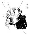
- Figure 1 is a perspective schematic view of the pump according to the invention;
- Figure 2 is a view from above of the pump of figure 1;
- Figure 3 shows a cross section according to the axis A-A of the pump of figure 2;
- Figure 4 schematically shows a synchronous electric motor equipped with a permanent magnet according to the invention;
- Figure 5 is a block diagram of a control unit according to the invention to determine the fluid temperature and the fluid presence in a pump driven by a synchronous electric motor.
- With reference to the figures, a washing fluid circulation pump in washing machines and the like is globally and schematically shown with 10. The
pump 10, realised according to the present invention, is equipped with fluid heating means 40 and it is driven by a synchronouselectric motor 14. - The
pump 10 can be realised in two modes, both falling however in the scope of the present invention. - A first mode provides a pump structure with an electronic control of the electric supply at the motor windings in order to regulate the motor operation in the start-up step and in load variation situations; while a second mode provides a more simplified structure with coupling joints between the rotor and the impeller in order to favour the motor start-up step.
- In the electronic control pump hypothesis, a control circuit comprising a power regulation circuit portion and a current regulation circuit portion is associated to the pump permanent-magnet synchronous electric motor.
- The kind of control adopted for the power regulation circuit is of the adaptive type, since the voltage applied to the synchronous electric motor windings is adapted to the load and line voltage conditions in order to reach the lowest absorbed power value, for example as described in the
European patent application no. 03425409.4 - To the purpose of the present invention the difference between the two pump embodiments is not very relevant but because in the one case the pump is already equipped with an electronic control circuit, while in the other case the pump must be equipped with a control unit, for example as shown in figure 5 and describe hereafter.
- The
synchronous motor 14, seen in figure 3, and partially in figure 4, comprises astator 15 being centrally crossed by a shell housing therotor 18. Therotor 18 is a permanent-magnet one and it is insulated tight with respect to thestator 15 by said shell. Said shell is closed at the top by avolute 17 housing animpeller 16. - The
rotor 18 is rotation-driven by the electromagnetic field generated by thestator 15, equipped withpole shoes 20 with the relevant windings, and it is integral with a x-x-axis rotation shaft. - Advantageously, as shown in figure 4, the
synchronous motor 14 comprises amagnetic flux sensor 22 of therotor 18, for example an analogue Hall sensor, arranged on thestator 15 close to therotor 18. - The rotation shaft of the
synchronous motor 14 is coupled at the top to theimpeller 16 by means of a known kinematic coupling, for example as described in theEuropean patent no. 0 983 630 by the same Applicant. - Preferably, the
impeller 16 is coaxial to the axis x-x, being arranged in alignment with an end of the rotation shaft. - The
synchronous motor 14 comprises aprotection pump body 13, preferably of thermoplastic material. - The
pump body 13 has sideways to thevolute 17, and in correspondence with theimpeller 16, a delivery opening 30 communicating with theimpeller 16 housing chamber. This delivery opening 30 has preferably an orthogonal axis to the axis x-x and it is arranged tangentially to thevolute 17 of theimpeller 16. Thepump body 13 has also, above theimpeller 16, acover 19 comprising a suction opening 31 wherefrom the fluid pumped by theimpeller 16 is sucked through the delivery opening 30. Thesuction opening 31 has preferably an axis being parallel to the axis x-x. - Externally, the
cover 19 houses the heating means 40. - These heating means 40 comprise a ring-shaped, substantially C-shaped,
resistance 41, being coaxial to the axis x-x and arranged near the periphery of thecover 19. The resistance is wrapped by a conductive material and in the case indicated in the figure it has a trapezoid cross section, with the larger base arranged near thecover 19 in order to allow a higher contact surface with thecover 19. - The
resistance 41 has at the two terminals twoclamps - Preferably the
fluid circulation pump 10 comprises acontrol unit 24 of the type shown in the block diagram of figure 5 which allows the synchronouselectric motor 14 to be monitored. When thepump 10 is an electronic control one, thecontrol unit 24 is meant to be incorporated and/or integrated in the pump control circuit. However, the control circuit eventually already existing in order to regulate the electric supply at the motor windings must be equipped with the componentry described hereafter for realising the present invention. - More particularly, a memory portion is associated to the
control unit 24 wherein correlation experimental data between the values of an operating variable of thesynchronous motor 14 of thepump 10 and the values corresponding to thepump 10 flow rate are stored. An operating variable of thesynchronous motor 14, during the steady operation thereof, is the measure of the load or lag angle ϑ representing the phase displacement between the voltage applied across thesynchronous motor 14 and the counter electromotive force caused by the sum of the effects of thestator 15 flux and of the flux induced by therotor 18 permanent magnet rotation. - The
control unit 24 receives at the input a signal from theanalogue Hall sensor 22, relating to the reading of the polarity inversion of therotor 18 magnet, moreover it receives anetwork clock signal 25 and a signal being proportional to the effective value of thenetwork voltage 26. - The
control unit 24 through a predetermined correlation, in the absence of corrective factors, defines the value of the load or lag angle ϑ and a correspondingflow rate value 50. - Advantageously, the
rotor 18 plunges in the operating fluid, and in this case the magnet temperature corresponds to the operating fluid one. This dependence is due to the fact that the ferromagnetic material composing therotor 18 has a residual magnetic induction BR varying according to the fluid temperature. - The
analogue Hall sensor 22 is capable to provide a sinusoidal signal with an amplitude being proportional to the residual induction BR of the ferromagnetic material composing therotor 18 and thus to provide the fluid temperature during the passage in thepump 10. - The
control unit 24 comprises means 35 allowing the fluid temperature to be drawn from the amplitude of the sinusoidal signal provided by theanalogue Hall sensor 22. - Moreover the
control unit 24 comprises means 36 to compare the drawn fluid temperature value with a threshold reference value. Upon reaching this threshold reference value themeans 36 allow acontrol signal 47 to be provided at the control unit output for cutting the electric power supply of the heating means 40 off. - The means 36 can conveniently comprise a comparator having at the input the threshold reference value, eventually inserted in the
control unit 24 memory, and the signal coming from themeans 35. Upon exceeding the threshold reference value the comparator outputs adigital signal 47 which, for example by means of a traditional D/A conversion, allows the operation on apower switch 43 inserted on the power supply line to theresistance 41, interrupting the supply itself. Obviously, nothing prevents the digital signal outputted from the comparator from being directly used to drive an inserted discrete or integrated electronic component as a switch on the power supply line towards the resistance. - As it may be easily understood by a skilled in the art, the
signal 47 outputted from thecontrol unit 24 can be also used by the washing machine producer in the hypothesis that heating means are driven by a washing programmer and not by means of switching devices mounted on board of thepump 10. - In other words, the
pump 10 can be structured with apower switch 43 in order to independently cut the power supply of the heating means 40 associated thereto off, or it can simply provide, on an output of thecontrol unit 24, and thus of the electronic circuit incorporating it, an analogue or digitalelectric signal 47 to be used in order to cut the power supply to the heating means 40 off by means of an external control unit, for example a washing machine programmer. - Moreover, advantageously, the
control unit 24 of thepump 10 can detect the fluid within thepump 10 through the value outputted from thecontrol unit 24, i.e. thepump 10 flow rate. Thus, through themeans 36, thecontrol unit 24 can compare the drawn value of theflow rate 50 with a threshold reference value, which in this case is conveniently a value near to zero. Upon reaching this threshold reference value, and thus without any fluid, themeans 36 allow the electric power supply to theresistance 41 to be cut off. - The main advantage reached by the present invention is to allow the fluid heating means to be controlled in a simple and reliable way, avoiding the use of temperature and pressure sensors.
- The synchronous motor pump controlled by the control unit as previously described can undergo some modifications, all within the reach of the skilled in the art and falling within the scope of protection of the present invention, as defined in the following claims.
Claims (10)
- A fluid circulation pump (10) with synchronous motor (14), equipped with fluid heating means (40), particularly for washing machines, of the type comprising a rotor (18),partially plunges is the operating fluid and equipped with a permanent magnet being rotation-driven by the electromagnetic field generated by a stator (15) equipped with pole shoes (20) with the corresponding windings, and a magnetic flux sensor (22) of said rotor (18), said rotor (18) being insulated tight with respect to said stator (15) by a shell closed at the top by a volute (17) housing an impeller (16) for the fluid circulationcharacterised in that it comprises a control unit (24) equipped with means (35) to draw by the signal provided from said magnetic flux sensor (22) parameters of the temperature and the flow rate of said fluid and means (36) to compare this parameter with a reference value and to output an electric signal (47) to be used to cut the power supply of said heating means (40) off upon reaching a threshold of said predetermined reference parameter.
- A circulation pump (10) according to claim 1,characterised in that said magnetic flux sensor (22) is of the analogue Hall type.
- A circulation pump (10) according to claim 1,characterised in that said heating means (40) are housed in a cover (19) of said volute (17) externally respect to said impeller (16).
- A circulation pump (10) according to claims 2 and 3,characterised in that said rotor (18) comprises some ferromagnetic material which has a residual magnetic induction BR, varying according to the temperature of said operating fluid, andin that said analogue Hall magnetic flux sensor (22) outputs a sinusoidal signal with a proportional amplitude to said residual magnetic induction DR.
- A pump according to claims 1, and 4,characterised in that said means 35 comprise a device being capable to draw from the sinusoidal signal coming from said analogue Hall sensor (22) the temperature value of said fluid.
- A pump according to claim 1, wherein said control unit (24) comprises a memory portion wherein correlation experimental data between the values of an operating variable of the synchronous motor (14) and the values corresponding to the pump (10) flow rate are stored, said operating variable of the synchronous motor (14) being the measure of the load or lag angle ϑ representing the phase displacement between the voltage applied across the synchronous motor (14) and the counter electromotive force caused by the sum of the effects of the stator (15) flux and of the flux induced by the rotor (18) permanent magnet rotation, drawn by the analogue Hall sensor (22),characterised in that the fluid presence in said pump (10) is detected by an output signal (50) of said control unit being proportional to said measure of the load or lag angle ϑ and to the fluid flow rate.
- A pump according to claims 5,characterised in that said means (36) to compare said temperature and/or said fluid presence comprise an analogue digital comparator allowing said temperature and/or said fluid presence to be compared with a reference value and an output signal (47) being capable to interrupt the power supply of said heating means (40) to be generated upon exceeding said reference value.
- A pump according to claim 6,characterised in that said output signal (47) of said means (36) is of the digital type and it operates on a switch (43) inserted on the power supply line to said heating means (40).
- A pump according to claim 1, wherein said control unit (24) is incorporated in an electronic circuit for controlling and regulating the power supply at the motor windings.
- A pump according to claim 1, wherein said control unit (24) is integrated in said electronic control circuit and it has a signal output (47) belonging to the outputs of said electronic control circuit.
Priority Applications (7)
| Application Number | Priority Date | Filing Date | Title |
|---|---|---|---|
| EP04425339AEP1595489B1 (en) | 2004-05-12 | 2004-05-12 | Fluid circulation pump with synchronous motor, equipped with heating means of the fluid, in particular for washing-machines |
| AT04425339TATE366542T1 (en) | 2004-05-12 | 2004-05-12 | LIQUID CIRCULATION PUMP WITH A SYNCHRONOUS MOTOR, EQUIPPED WITH A DEVICE FOR HEATING THE LIQUID, ESPECIALLY FOR WASHING MACHINES |
| DE602004007488TDE602004007488T2 (en) | 2004-05-12 | 2004-05-12 | Liquid circulation pump with a synchronous motor, equipped with a device for heating the liquid, in particular for washing machines |
| ES04425339TES2290659T3 (en) | 2004-05-12 | 2004-05-12 | FLUID CIRCULATION PUMP WITH SYNCHRONIC MOTOR, EQUIPPED WITH FLUID HEATING MEDIA, IN PARTICULAR FOR WASHERS. |
| US11/126,037US7607895B2 (en) | 2004-05-12 | 2005-05-10 | Fluid circulation pump with synchronous motor, equipped with heating means of the fluid, in particular for washing machines |
| CN2005100817390ACN1702334B (en) | 2004-05-12 | 2005-05-12 | Fluid circulation pump with synchronous motor and equipped with fluid heating, especially for washing machines |
| KR1020050039611AKR101120146B1 (en) | 2004-05-12 | 2005-05-12 | Fluid circulation pump with synchronous motor, equipped with heating means of the fluid, in particular for washing machines |
Applications Claiming Priority (1)
| Application Number | Priority Date | Filing Date | Title |
|---|---|---|---|
| EP04425339AEP1595489B1 (en) | 2004-05-12 | 2004-05-12 | Fluid circulation pump with synchronous motor, equipped with heating means of the fluid, in particular for washing-machines |
Publications (2)
| Publication Number | Publication Date |
|---|---|
| EP1595489A1 EP1595489A1 (en) | 2005-11-16 |
| EP1595489B1true EP1595489B1 (en) | 2007-07-11 |
Family
ID=34932491
Family Applications (1)
| Application Number | Title | Priority Date | Filing Date |
|---|---|---|---|
| EP04425339AExpired - LifetimeEP1595489B1 (en) | 2004-05-12 | 2004-05-12 | Fluid circulation pump with synchronous motor, equipped with heating means of the fluid, in particular for washing-machines |
Country Status (7)
| Country | Link |
|---|---|
| US (1) | US7607895B2 (en) |
| EP (1) | EP1595489B1 (en) |
| KR (1) | KR101120146B1 (en) |
| CN (1) | CN1702334B (en) |
| AT (1) | ATE366542T1 (en) |
| DE (1) | DE602004007488T2 (en) |
| ES (1) | ES2290659T3 (en) |
Families Citing this family (15)
| Publication number | Priority date | Publication date | Assignee | Title |
|---|---|---|---|---|
| ES2351271B1 (en)* | 2009-01-26 | 2011-11-15 | Coprecitec, S.L. | FLUID CIRCULATION PUMP ADAPTED TO AN APPLIANCES. |
| US20110240070A1 (en)* | 2010-03-30 | 2011-10-06 | Emerson Electric Co. | Offset Inlet Dishwasher Pumps |
| DE102012202065B3 (en)* | 2012-02-10 | 2013-05-29 | E.G.O. Elektro-Gerätebau GmbH | Pump and method for heating a pump |
| DE102012203715A1 (en)* | 2012-03-08 | 2013-09-12 | BSH Bosch und Siemens Hausgeräte GmbH | Water-conducting household appliance with at least one motor-driven pump and a heating device |
| DE102014109625A1 (en)* | 2014-07-09 | 2016-01-14 | Hanning Elektro-Werke Gmbh & Co. Kg | pump assembly |
| CN109854538B (en)* | 2014-08-07 | 2021-01-12 | 德昌电机(深圳)有限公司 | Heating pump |
| DE102014220019A1 (en)* | 2014-10-02 | 2016-04-07 | BSH Hausgeräte GmbH | Laundry care device with a heating element |
| KR102443320B1 (en)* | 2016-01-05 | 2022-09-15 | 엘지전자 주식회사 | Dish washer and controlling method thereof |
| CN105604986A (en)* | 2016-03-02 | 2016-05-25 | 广东格兰仕集团有限公司 | Heating pump of dishwasher |
| KR102568000B1 (en)* | 2017-02-23 | 2023-08-18 | 엘지전자 주식회사 | Washing machine |
| CN109088486B (en)* | 2017-09-28 | 2019-12-13 | 黄文佳 | stator module of axial flow water pump |
| CN108167230B (en)* | 2017-12-19 | 2020-03-31 | 佛山市威灵洗涤电机制造有限公司 | Heating pump and washing electric appliance |
| CN110960172A (en)* | 2018-09-30 | 2020-04-07 | 青岛海尔洗碗机有限公司 | A heating device for a washing pump |
| CN117321309A (en)* | 2021-05-12 | 2023-12-29 | 格兰富控股公司 | centrifugal pump |
| CN113355872A (en)* | 2021-06-11 | 2021-09-07 | 珠海格力电器股份有限公司 | Door body washing mechanism with temperature sensing function and washing device |
Family Cites Families (10)
| Publication number | Priority date | Publication date | Assignee | Title |
|---|---|---|---|---|
| FR2102756A5 (en)* | 1970-08-20 | 1972-04-07 | Unelec | DEVICE FOR DETECTION OF THERMAL OVERLOADS OF A ROTATING ORGAN. |
| DE3627732A1 (en)* | 1986-08-16 | 1988-02-18 | Ego Italiana | Conveying device for flowing substances, in particular wash solutions |
| DE4010049C1 (en)* | 1990-03-29 | 1991-10-10 | Grundfos International A/S, Bjerringbro, Dk | Pump unit for heating or cooling circuit - uses frequency regulator to reduce rotation of pump motor upon detected overheating |
| DE4137559A1 (en)* | 1991-11-15 | 1993-05-19 | Heidelberger Druckmasch Ag | DEVICE FOR DETECTING AT LEAST ONE STATE SIZE OF A BRUSHLESS DC MOTOR |
| CA2378132C (en)* | 1991-12-20 | 2004-08-17 | Fisher & Paykel Appliances Limited | Dishwasher |
| DE19852569A1 (en)* | 1998-11-13 | 2000-05-18 | Miele & Cie | Circulation pump, in particular for water-bearing household appliances |
| IT1315436B1 (en)* | 2000-04-27 | 2003-02-10 | Askoll Holding Srl | STRUCTURE OF PERMANENT MAGNET ELECTRIC MOTOR FOR CIRCULATION PUMPS OF HEATING SYSTEMS. |
| ES2229078T3 (en)* | 2002-03-05 | 2005-04-16 | Askoll Holding S.R.L. | ELECTRONIC DEVICE TO START A PERMANENT MAGNET SYNCHRON MOTOR. |
| DE60310929T2 (en)* | 2003-09-04 | 2007-10-11 | Askoll Holding S.R.L., Povolaro Di Dueville | Method and device for determining the hydraulic flow in a pump |
| DE102004007246A1 (en)* | 2004-02-13 | 2005-09-01 | BSH Bosch und Siemens Hausgeräte GmbH | Liquid household electrical appliance |
- 2004
- 2004-05-12EPEP04425339Apatent/EP1595489B1/ennot_activeExpired - Lifetime
- 2004-05-12ESES04425339Tpatent/ES2290659T3/ennot_activeExpired - Lifetime
- 2004-05-12ATAT04425339Tpatent/ATE366542T1/ennot_activeIP Right Cessation
- 2004-05-12DEDE602004007488Tpatent/DE602004007488T2/ennot_activeExpired - Lifetime
- 2005
- 2005-05-10USUS11/126,037patent/US7607895B2/enactiveActive
- 2005-05-12KRKR1020050039611Apatent/KR101120146B1/ennot_activeExpired - Lifetime
- 2005-05-12CNCN2005100817390Apatent/CN1702334B/ennot_activeExpired - Lifetime
Non-Patent Citations (1)
| Title |
|---|
| None* |
Also Published As
| Publication number | Publication date |
|---|---|
| EP1595489A1 (en) | 2005-11-16 |
| ES2290659T3 (en) | 2008-02-16 |
| DE602004007488T2 (en) | 2008-03-20 |
| ATE366542T1 (en) | 2007-08-15 |
| US20050260087A1 (en) | 2005-11-24 |
| KR20060047794A (en) | 2006-05-18 |
| DE602004007488D1 (en) | 2007-08-23 |
| CN1702334B (en) | 2011-11-23 |
| CN1702334A (en) | 2005-11-30 |
| US7607895B2 (en) | 2009-10-27 |
| KR101120146B1 (en) | 2012-02-22 |
Similar Documents
| Publication | Publication Date | Title |
|---|---|---|
| EP1595489B1 (en) | Fluid circulation pump with synchronous motor, equipped with heating means of the fluid, in particular for washing-machines | |
| JP3658310B2 (en) | PWM control circuit, electric blower and vacuum cleaner | |
| US6775468B2 (en) | Dishwasher pump drive | |
| AU2019334749B2 (en) | Drain pump driving apparatus and laundry processing machine comprising same | |
| US6445101B2 (en) | Clutchless motor drive system | |
| JP5750571B2 (en) | Washing machine | |
| US10680498B2 (en) | Motor and electric equipment with the same | |
| US7068008B2 (en) | Electronic device for controlling a discharge pump driven by a synchronous electric motor with a permanent-magnet rotor | |
| JP3769138B2 (en) | Pump device | |
| JP4457857B2 (en) | Washing and drying machine | |
| JP2005143531A (en) | Washing machine | |
| KR20200005377A (en) | Drain pump driving apparatus and laundry treatment machine including the same | |
| EP2070461B1 (en) | Pump for a dishwashing machine and corresponding pump assembly and dishwashing machine | |
| US12006616B2 (en) | Drain pump driving apparatus and laundry treatment machine including the same | |
| KR100407046B1 (en) | Safety circuit of a clothes drier | |
| WO2011073127A1 (en) | Control card for the brushless direct current motor | |
| US11718946B2 (en) | Laundry treatment machine | |
| US12289075B2 (en) | Method for controlling the direction of rotation of a fluid machine and processing unit configured to perform said method | |
| US11739459B2 (en) | Laundry treatment machine | |
| JP2011200520A (en) | Washing machine | |
| KR20170017839A (en) | Magnetic sensor integrated circuit and motor assembly |
Legal Events
| Date | Code | Title | Description |
|---|---|---|---|
| PUAI | Public reference made under article 153(3) epc to a published international application that has entered the european phase | Free format text:ORIGINAL CODE: 0009012 | |
| AK | Designated contracting states | Kind code of ref document:A1 Designated state(s):AT BE BG CH CY CZ DE DK EE ES FI FR GB GR HU IE IT LI LU MC NL PL PT RO SE SI SK TR | |
| AX | Request for extension of the european patent | Extension state:AL HR LT LV MK | |
| 17P | Request for examination filed | Effective date:20060515 | |
| AKX | Designation fees paid | Designated state(s):AT BE BG CH CY CZ DE DK EE ES FI FR GB GR HU IE IT LI LU MC NL PL PT RO SE SI SK TR | |
| GRAP | Despatch of communication of intention to grant a patent | Free format text:ORIGINAL CODE: EPIDOSNIGR1 | |
| GRAS | Grant fee paid | Free format text:ORIGINAL CODE: EPIDOSNIGR3 | |
| GRAA | (expected) grant | Free format text:ORIGINAL CODE: 0009210 | |
| AK | Designated contracting states | Kind code of ref document:B1 Designated state(s):AT BE BG CH CY CZ DE DK EE ES FI FR GB GR HU IE IT LI LU MC NL PL PT RO SE SI SK TR | |
| REG | Reference to a national code | Ref country code:GB Ref legal event code:FG4D | |
| REG | Reference to a national code | Ref country code:CH Ref legal event code:EP | |
| REF | Corresponds to: | Ref document number:602004007488 Country of ref document:DE Date of ref document:20070823 Kind code of ref document:P | |
| REG | Reference to a national code | Ref country code:IE Ref legal event code:FG4D | |
| ET | Fr: translation filed | ||
| PG25 | Lapsed in a contracting state [announced via postgrant information from national office to epo] | Ref country code:NL Free format text:LAPSE BECAUSE OF FAILURE TO SUBMIT A TRANSLATION OF THE DESCRIPTION OR TO PAY THE FEE WITHIN THE PRESCRIBED TIME-LIMIT Effective date:20070711 Ref country code:BG Free format text:LAPSE BECAUSE OF FAILURE TO SUBMIT A TRANSLATION OF THE DESCRIPTION OR TO PAY THE FEE WITHIN THE PRESCRIBED TIME-LIMIT Effective date:20071011 Ref country code:FI Free format text:LAPSE BECAUSE OF FAILURE TO SUBMIT A TRANSLATION OF THE DESCRIPTION OR TO PAY THE FEE WITHIN THE PRESCRIBED TIME-LIMIT Effective date:20070711 Ref country code:PT Free format text:LAPSE BECAUSE OF FAILURE TO SUBMIT A TRANSLATION OF THE DESCRIPTION OR TO PAY THE FEE WITHIN THE PRESCRIBED TIME-LIMIT Effective date:20071211 | |
| REG | Reference to a national code | Ref country code:CH Ref legal event code:PL | |
| NLV1 | Nl: lapsed or annulled due to failure to fulfill the requirements of art. 29p and 29m of the patents act | ||
| REG | Reference to a national code | Ref country code:ES Ref legal event code:FG2A Ref document number:2290659 Country of ref document:ES Kind code of ref document:T3 | |
| PG25 | Lapsed in a contracting state [announced via postgrant information from national office to epo] | Ref country code:CH Free format text:LAPSE BECAUSE OF FAILURE TO SUBMIT A TRANSLATION OF THE DESCRIPTION OR TO PAY THE FEE WITHIN THE PRESCRIBED TIME-LIMIT Effective date:20070711 Ref country code:LI Free format text:LAPSE BECAUSE OF FAILURE TO SUBMIT A TRANSLATION OF THE DESCRIPTION OR TO PAY THE FEE WITHIN THE PRESCRIBED TIME-LIMIT Effective date:20070711 Ref country code:AT Free format text:LAPSE BECAUSE OF FAILURE TO SUBMIT A TRANSLATION OF THE DESCRIPTION OR TO PAY THE FEE WITHIN THE PRESCRIBED TIME-LIMIT Effective date:20070711 Ref country code:PL Free format text:LAPSE BECAUSE OF FAILURE TO SUBMIT A TRANSLATION OF THE DESCRIPTION OR TO PAY THE FEE WITHIN THE PRESCRIBED TIME-LIMIT Effective date:20070711 | |
| PG25 | Lapsed in a contracting state [announced via postgrant information from national office to epo] | Ref country code:BE Free format text:LAPSE BECAUSE OF FAILURE TO SUBMIT A TRANSLATION OF THE DESCRIPTION OR TO PAY THE FEE WITHIN THE PRESCRIBED TIME-LIMIT Effective date:20070711 | |
| PG25 | Lapsed in a contracting state [announced via postgrant information from national office to epo] | Ref country code:GR Free format text:LAPSE BECAUSE OF FAILURE TO SUBMIT A TRANSLATION OF THE DESCRIPTION OR TO PAY THE FEE WITHIN THE PRESCRIBED TIME-LIMIT Effective date:20071012 Ref country code:DK Free format text:LAPSE BECAUSE OF FAILURE TO SUBMIT A TRANSLATION OF THE DESCRIPTION OR TO PAY THE FEE WITHIN THE PRESCRIBED TIME-LIMIT Effective date:20070711 | |
| PLBE | No opposition filed within time limit | Free format text:ORIGINAL CODE: 0009261 | |
| STAA | Information on the status of an ep patent application or granted ep patent | Free format text:STATUS: NO OPPOSITION FILED WITHIN TIME LIMIT | |
| PG25 | Lapsed in a contracting state [announced via postgrant information from national office to epo] | Ref country code:SK Free format text:LAPSE BECAUSE OF FAILURE TO SUBMIT A TRANSLATION OF THE DESCRIPTION OR TO PAY THE FEE WITHIN THE PRESCRIBED TIME-LIMIT Effective date:20070711 Ref country code:CZ Free format text:LAPSE BECAUSE OF FAILURE TO SUBMIT A TRANSLATION OF THE DESCRIPTION OR TO PAY THE FEE WITHIN THE PRESCRIBED TIME-LIMIT Effective date:20070711 | |
| 26N | No opposition filed | Effective date:20080414 | |
| PG25 | Lapsed in a contracting state [announced via postgrant information from national office to epo] | Ref country code:SE Free format text:LAPSE BECAUSE OF FAILURE TO SUBMIT A TRANSLATION OF THE DESCRIPTION OR TO PAY THE FEE WITHIN THE PRESCRIBED TIME-LIMIT Effective date:20071011 Ref country code:RO Free format text:LAPSE BECAUSE OF FAILURE TO SUBMIT A TRANSLATION OF THE DESCRIPTION OR TO PAY THE FEE WITHIN THE PRESCRIBED TIME-LIMIT Effective date:20070711 | |
| PG25 | Lapsed in a contracting state [announced via postgrant information from national office to epo] | Ref country code:MC Free format text:LAPSE BECAUSE OF NON-PAYMENT OF DUE FEES Effective date:20080531 | |
| PG25 | Lapsed in a contracting state [announced via postgrant information from national office to epo] | Ref country code:EE Free format text:LAPSE BECAUSE OF FAILURE TO SUBMIT A TRANSLATION OF THE DESCRIPTION OR TO PAY THE FEE WITHIN THE PRESCRIBED TIME-LIMIT Effective date:20070711 | |
| PG25 | Lapsed in a contracting state [announced via postgrant information from national office to epo] | Ref country code:IE Free format text:LAPSE BECAUSE OF NON-PAYMENT OF DUE FEES Effective date:20080512 | |
| PG25 | Lapsed in a contracting state [announced via postgrant information from national office to epo] | Ref country code:SI Free format text:LAPSE BECAUSE OF FAILURE TO SUBMIT A TRANSLATION OF THE DESCRIPTION OR TO PAY THE FEE WITHIN THE PRESCRIBED TIME-LIMIT Effective date:20070711 | |
| PG25 | Lapsed in a contracting state [announced via postgrant information from national office to epo] | Ref country code:CY Free format text:LAPSE BECAUSE OF FAILURE TO SUBMIT A TRANSLATION OF THE DESCRIPTION OR TO PAY THE FEE WITHIN THE PRESCRIBED TIME-LIMIT Effective date:20070711 | |
| PG25 | Lapsed in a contracting state [announced via postgrant information from national office to epo] | Ref country code:LU Free format text:LAPSE BECAUSE OF NON-PAYMENT OF DUE FEES Effective date:20080512 Ref country code:HU Free format text:LAPSE BECAUSE OF FAILURE TO SUBMIT A TRANSLATION OF THE DESCRIPTION OR TO PAY THE FEE WITHIN THE PRESCRIBED TIME-LIMIT Effective date:20080112 | |
| REG | Reference to a national code | Ref country code:FR Ref legal event code:PLFP Year of fee payment:13 | |
| REG | Reference to a national code | Ref country code:FR Ref legal event code:PLFP Year of fee payment:14 | |
| REG | Reference to a national code | Ref country code:FR Ref legal event code:PLFP Year of fee payment:15 | |
| PGFP | Annual fee paid to national office [announced via postgrant information from national office to epo] | Ref country code:IT Payment date:20230420 Year of fee payment:20 Ref country code:FR Payment date:20230420 Year of fee payment:20 Ref country code:ES Payment date:20230601 Year of fee payment:20 Ref country code:DE Payment date:20230419 Year of fee payment:20 | |
| PGFP | Annual fee paid to national office [announced via postgrant information from national office to epo] | Ref country code:TR Payment date:20230428 Year of fee payment:20 | |
| PGFP | Annual fee paid to national office [announced via postgrant information from national office to epo] | Ref country code:GB Payment date:20230420 Year of fee payment:20 | |
| REG | Reference to a national code | Ref country code:DE Ref legal event code:R071 Ref document number:602004007488 Country of ref document:DE | |
| REG | Reference to a national code | Ref country code:ES Ref legal event code:FD2A Effective date:20240524 | |
| REG | Reference to a national code | Ref country code:GB Ref legal event code:PE20 Expiry date:20240511 | |
| PG25 | Lapsed in a contracting state [announced via postgrant information from national office to epo] | Ref country code:GB Free format text:LAPSE BECAUSE OF EXPIRATION OF PROTECTION Effective date:20240511 | |
| PG25 | Lapsed in a contracting state [announced via postgrant information from national office to epo] | Ref country code:ES Free format text:LAPSE BECAUSE OF EXPIRATION OF PROTECTION Effective date:20240513 | |
| PG25 | Lapsed in a contracting state [announced via postgrant information from national office to epo] | Ref country code:GB Free format text:LAPSE BECAUSE OF EXPIRATION OF PROTECTION Effective date:20240511 Ref country code:ES Free format text:LAPSE BECAUSE OF EXPIRATION OF PROTECTION Effective date:20240513 |