EP1592893B1 - Screw comprising an integrated screwdriver - Google Patents
Screw comprising an integrated screwdriverDownload PDFInfo
- Publication number
- EP1592893B1 EP1592893B1EP03700801AEP03700801AEP1592893B1EP 1592893 B1EP1592893 B1EP 1592893B1EP 03700801 AEP03700801 AEP 03700801AEP 03700801 AEP03700801 AEP 03700801AEP 1592893 B1EP1592893 B1EP 1592893B1
- Authority
- EP
- European Patent Office
- Prior art keywords
- screw
- integrated
- thread
- diameter
- driver
- Prior art date
- Legal status (The legal status is an assumption and is not a legal conclusion. Google has not performed a legal analysis and makes no representation as to the accuracy of the status listed.)
- Revoked
Links
- 210000000988bone and boneAnatomy0.000claimsdescription12
- 238000010079rubber tappingMethods0.000description2
- 238000004873anchoringMethods0.000description1
- 230000008878couplingEffects0.000description1
- 238000010168coupling processMethods0.000description1
- 238000005859coupling reactionMethods0.000description1
- 230000001419dependent effectEffects0.000description1
- 238000011161developmentMethods0.000description1
- 230000018109developmental processEffects0.000description1
- 238000001356surgical procedureMethods0.000description1
Images

Classifications
- A—HUMAN NECESSITIES
- A61—MEDICAL OR VETERINARY SCIENCE; HYGIENE
- A61B—DIAGNOSIS; SURGERY; IDENTIFICATION
- A61B17/00—Surgical instruments, devices or methods
- A61B17/56—Surgical instruments or methods for treatment of bones or joints; Devices specially adapted therefor
- A61B17/58—Surgical instruments or methods for treatment of bones or joints; Devices specially adapted therefor for osteosynthesis, e.g. bone plates, screws or setting implements
- A61B17/68—Internal fixation devices, including fasteners and spinal fixators, even if a part thereof projects from the skin
- A61B17/80—Cortical plates, i.e. bone plates; Instruments for holding or positioning cortical plates, or for compressing bones attached to cortical plates
- A61B17/8052—Cortical plates, i.e. bone plates; Instruments for holding or positioning cortical plates, or for compressing bones attached to cortical plates immobilised relative to screws by interlocking form of the heads and plate holes, e.g. conical or threaded
- A61B17/8057—Cortical plates, i.e. bone plates; Instruments for holding or positioning cortical plates, or for compressing bones attached to cortical plates immobilised relative to screws by interlocking form of the heads and plate holes, e.g. conical or threaded the interlocking form comprising a thread
- A—HUMAN NECESSITIES
- A61—MEDICAL OR VETERINARY SCIENCE; HYGIENE
- A61B—DIAGNOSIS; SURGERY; IDENTIFICATION
- A61B17/00—Surgical instruments, devices or methods
- A61B17/56—Surgical instruments or methods for treatment of bones or joints; Devices specially adapted therefor
- A61B17/58—Surgical instruments or methods for treatment of bones or joints; Devices specially adapted therefor for osteosynthesis, e.g. bone plates, screws or setting implements
- A61B17/68—Internal fixation devices, including fasteners and spinal fixators, even if a part thereof projects from the skin
- A61B17/84—Fasteners therefor or fasteners being internal fixation devices
- A61B17/86—Pins or screws or threaded wires; nuts therefor
- B—PERFORMING OPERATIONS; TRANSPORTING
- B25—HAND TOOLS; PORTABLE POWER-DRIVEN TOOLS; MANIPULATORS
- B25B—TOOLS OR BENCH DEVICES NOT OTHERWISE PROVIDED FOR, FOR FASTENING, CONNECTING, DISENGAGING OR HOLDING
- B25B15/00—Screwdrivers
- F—MECHANICAL ENGINEERING; LIGHTING; HEATING; WEAPONS; BLASTING
- F16—ENGINEERING ELEMENTS AND UNITS; GENERAL MEASURES FOR PRODUCING AND MAINTAINING EFFECTIVE FUNCTIONING OF MACHINES OR INSTALLATIONS; THERMAL INSULATION IN GENERAL
- F16B—DEVICES FOR FASTENING OR SECURING CONSTRUCTIONAL ELEMENTS OR MACHINE PARTS TOGETHER, e.g. NAILS, BOLTS, CIRCLIPS, CLAMPS, CLIPS OR WEDGES; JOINTS OR JOINTING
- F16B31/00—Screwed connections specially modified in view of tensile load; Break-bolts
- F16B31/02—Screwed connections specially modified in view of tensile load; Break-bolts for indicating the attainment of a particular tensile load or limiting tensile load
- F16B31/021—Screwed connections specially modified in view of tensile load; Break-bolts for indicating the attainment of a particular tensile load or limiting tensile load by means of a frangible part
- F—MECHANICAL ENGINEERING; LIGHTING; HEATING; WEAPONS; BLASTING
- F16—ENGINEERING ELEMENTS AND UNITS; GENERAL MEASURES FOR PRODUCING AND MAINTAINING EFFECTIVE FUNCTIONING OF MACHINES OR INSTALLATIONS; THERMAL INSULATION IN GENERAL
- F16B—DEVICES FOR FASTENING OR SECURING CONSTRUCTIONAL ELEMENTS OR MACHINE PARTS TOGETHER, e.g. NAILS, BOLTS, CIRCLIPS, CLAMPS, CLIPS OR WEDGES; JOINTS OR JOINTING
- F16B35/00—Screw-bolts; Stay-bolts; Screw-threaded studs; Screws; Set screws
- F16B35/04—Screw-bolts; Stay-bolts; Screw-threaded studs; Screws; Set screws with specially-shaped head or shaft in order to fix the bolt on or in an object
- F16B35/06—Specially-shaped heads
- A—HUMAN NECESSITIES
- A61—MEDICAL OR VETERINARY SCIENCE; HYGIENE
- A61B—DIAGNOSIS; SURGERY; IDENTIFICATION
- A61B17/00—Surgical instruments, devices or methods
- A61B17/56—Surgical instruments or methods for treatment of bones or joints; Devices specially adapted therefor
- A61B17/58—Surgical instruments or methods for treatment of bones or joints; Devices specially adapted therefor for osteosynthesis, e.g. bone plates, screws or setting implements
- A61B17/68—Internal fixation devices, including fasteners and spinal fixators, even if a part thereof projects from the skin
- A61B17/84—Fasteners therefor or fasteners being internal fixation devices
- A61B17/86—Pins or screws or threaded wires; nuts therefor
- A61B17/8625—Shanks, i.e. parts contacting bone tissue
- A—HUMAN NECESSITIES
- A61—MEDICAL OR VETERINARY SCIENCE; HYGIENE
- A61B—DIAGNOSIS; SURGERY; IDENTIFICATION
- A61B17/00—Surgical instruments, devices or methods
- A61B17/56—Surgical instruments or methods for treatment of bones or joints; Devices specially adapted therefor
- A61B17/58—Surgical instruments or methods for treatment of bones or joints; Devices specially adapted therefor for osteosynthesis, e.g. bone plates, screws or setting implements
- A61B17/88—Osteosynthesis instruments; Methods or means for implanting or extracting internal or external fixation devices
- A61B17/8875—Screwdrivers, spanners or wrenches
- A—HUMAN NECESSITIES
- A61—MEDICAL OR VETERINARY SCIENCE; HYGIENE
- A61B—DIAGNOSIS; SURGERY; IDENTIFICATION
- A61B90/00—Instruments, implements or accessories specially adapted for surgery or diagnosis and not covered by any of the groups A61B1/00 - A61B50/00, e.g. for luxation treatment or for protecting wound edges
- A61B90/03—Automatic limiting or abutting means, e.g. for safety
- A61B2090/037—Automatic limiting or abutting means, e.g. for safety with a frangible part, e.g. by reduced diameter
- Y—GENERAL TAGGING OF NEW TECHNOLOGICAL DEVELOPMENTS; GENERAL TAGGING OF CROSS-SECTIONAL TECHNOLOGIES SPANNING OVER SEVERAL SECTIONS OF THE IPC; TECHNICAL SUBJECTS COVERED BY FORMER USPC CROSS-REFERENCE ART COLLECTIONS [XRACs] AND DIGESTS
- Y10—TECHNICAL SUBJECTS COVERED BY FORMER USPC
- Y10S—TECHNICAL SUBJECTS COVERED BY FORMER USPC CROSS-REFERENCE ART COLLECTIONS [XRACs] AND DIGESTS
- Y10S606/00—Surgery
- Y10S606/916—Tool for installing or removing orthopedic fastener
Definitions
- the inventionrelates to a screw with integrated screwdriver according to the preamble of patent claim 1.
- a screw according to the preamble of claim 1is known for example from document FR 2 721 819.
- the inventionaims to remedy this situation.
- the inventionhas for its object to provide an angle stable anchorable screw with a built-in breakpoint over a screwdriver, so that the screw with a predetermined torque, can be safely locked angular stable.
- the inventionsolves the problem set with a screw having the features of claim 1.
- the inventive screw with integrated screwdriveralso allows very small screws to be kept simple and well guided in a bore, e.g. to screw in a bone plate. Due to the coaxial arrangement of the integrated screwdriver and its fixed connection to the screw head, the screw can be taken in any position about the longitudinal axis and it does not have to take into account the position of the screwdriver.
- the screw headwidens conically in the direction of the screwdriver, which allows a fixed-angle fixation of the screw head in a bone plate with a corresponding conical plate bore.
- the thread of the screw shaftis self-tapping formed by a corresponding groove is mounted at its free end, that is, at the screw tip, which extends substantially parallel to the longitudinal axis of the screw.
- the inventive deviceis particularly suitable for small-sized screws, typically those with a diameter smaller than 2.0 mm, preferably smaller than 1.0 mm.
- the predetermined breaking pointshould advantageously have a diameter which is smaller than the diameter of the threaded tap between the screw shaft and the screw head.
- the predetermined breaking pointhas a diameter of 60 to 82%, preferably from 66 to 75% of the outer diameter of the thread.
- the predetermined breaking pointmay have a diameter of 0.25 to 0.5 mm, preferably 0.32 to 0.38 mm
- the screw with integrated screwdrivercan be connected to a mechanical drive via a coupling.
- This drivecan be either a manually operable handle or a motor actuatable machine.
- the screw 1 and the integrated screwdriver 2 shown in FIGS. 1 and 2have a common longitudinal axis 6.
- the trained as a bone screw screw 1has a length of 2.6 mm and has a screw shaft 3 of length 1.3 mm with a thread 4 and a conical screw head 5 of length 1.1 mm with external thread 8. Between screw shaft 3 and screw head 5, a thread undercut 9 is arranged.
- the thread 4 of the screw shaft 3is formed by means of a groove 10 self-tapping.
- the screwdriver 2is 4.9 mm long and connected via a predetermined breaking point 7 coaxial with the screw head 5.
- the predetermined breaking pointhas a diameter of 0.35 mm.
- the screw 1can be inserted into the plate bore 13 of the bone plate 12 shown in FIG.
- the internal thread 14 of the plate bore 13 corresponding to the external thread 8 of the screw 1causes an angularly stable anchoring of the screw 1 with respect to the bone plate 12.
- the internal thread 14 and the thereto corresponding external threads 8can also be multi-threaded, preferably double-threaded.
Landscapes
- Health & Medical Sciences (AREA)
- Orthopedic Medicine & Surgery (AREA)
- Engineering & Computer Science (AREA)
- Life Sciences & Earth Sciences (AREA)
- General Engineering & Computer Science (AREA)
- Surgery (AREA)
- Mechanical Engineering (AREA)
- Biomedical Technology (AREA)
- Nuclear Medicine, Radiotherapy & Molecular Imaging (AREA)
- Heart & Thoracic Surgery (AREA)
- Medical Informatics (AREA)
- Molecular Biology (AREA)
- Animal Behavior & Ethology (AREA)
- General Health & Medical Sciences (AREA)
- Public Health (AREA)
- Veterinary Medicine (AREA)
- Neurology (AREA)
- Surgical Instruments (AREA)
- Details Of Spanners, Wrenches, And Screw Drivers And Accessories (AREA)
Description
Translated fromGermanDie Erfindung bezieht sich auf eine Schraube mit integriertem Schraubendreher gemäss dem Oberbegriff des Patentanspruchs 1.The invention relates to a screw with integrated screwdriver according to the preamble of
Insbesondere bei Schrauben mit kleinen Abmessungen, wie sie beispielsweise in der Osteosynthese Verwendung finden, stellt sich das Problem der sicheren Handhabung, des Haltens und des Führens. Bereits das Ergreifen kleinerer Schrauben, im besonderen bei anspruchsvollen Aufgaben, wie sie sich beispielsweise in der Knochenchirurgie stellen, kann sich äusserst schwierig gestalten.Especially with screws with small dimensions, as used for example in osteosynthesis, there is the problem of safe handling, holding and guiding. Even taking smaller screws, especially for challenging tasks, such as those in bone surgery, can be extremely difficult.
Ein weiteres Problem besteht darin, dass mit gewöhnlichen Schraubendrehern keine Kontrolle des Drehmomentes möglich ist. Um ein im voraus bestimmtes Drehmoment anwenden zu können, sind spezielle Drehmomentschraubendreher notwendig.Another problem is that with ordinary screwdrivers no control of the torque is possible. In order to apply a predetermined torque, special torque screwdrivers are necessary.
Eine Schraube gemäss dem Oberbegriff des Anspruchs 1 ist beispielsweise aus dem Dokument FR 2 721 819 bekannt.A screw according to the preamble of
Hier will die Erfindung Abhilfe schaffen. Der Erfindung liegt die Aufgabe zugrunde, eine winkelstabil verankerbare Schraube mit einem über eine Sollbruchstelle integrierten Schraubendreher zu schaffen, so dass die Schraube mit einem vorbestimmten Drehmoment, einfach und sicher winkelstabil eingedreht werden kann.The invention aims to remedy this situation. The invention has for its object to provide an angle stable anchorable screw with a built-in breakpoint over a screwdriver, so that the screw with a predetermined torque, can be safely locked angular stable.
Die Erfindung löst die gestellte Aufgabe mit einer Schraube, welche die Merkmale des Anspruchs 1 aufweist.The invention solves the problem set with a screw having the features of
Durch das am Schraubenkopf angebrachte Aussengewinde, welches mit einem entsprechenden (kreiszylindrischen oder konischen) Innengewinde in der Plattenbohrung korrespondiert wird sichergestellt, dass die Platte nicht an den Knochen herangepresst wird und die Schraube sicher und winkelstabil in der Platte verankert ist und auch bleibt. Dies steht im Gegensatz zu einer glatten konischen Ausführung des Schraubenkopfes, bei welcher der Kopf nur auf Grund der Reibkraft festsitzt und somit keinen Formschluss aufweist. Der nur auf der Reibkraft basierende Reibschluss entsteht durch Gegenhalt vom Knochen beim Festziehen der Schraube und hat den Nachteil, dass er sich durch Belastung der Schraube wiederum lösen kann.By the screw head attached to the external thread, which corresponds with a corresponding (circular cylindrical or conical) internal thread in the plate bore ensures that the plate is not pressed against the bone and the screw is anchored securely and stable angle in the plate and remains. This is in contrast to a smooth conical design of the screw head, in which the head is stuck only due to the frictional force and thus has no positive connection. The frictional engagement, which is based on the frictional force, is created by holding it against the bone when tightening the screw and has the disadvantage that it can be released by loading the screw.
Beim Festziehen der Schraube wird der integrierte Schraubendreher an der Sollbruchstelle abgeschert, wobei das Abschermoment durch die gewählte Dimensionierung der Sollbruchstelle definiert ist.When tightening the screw of the integrated screwdriver sheared off at the predetermined breaking point, wherein the Abschermoment is defined by the selected dimensioning of the predetermined breaking point.
Die erfindungsgemässe Schraube mit integriertem Schraubendreher gestattet auch sehr klein dimensionierte Schrauben einfach zu halten und gut geführt in eine Bohrung, z.B. einer Knochenplatte einzudrehen. Durch die koaxiale Anordnung des integrierten Schraubendrehers und seine feste Verbindung mit dem Schraubenkopf, kann die Schraube in jeder beliebigen Position um die Längsachse aufgenommen werden und es muss nicht auf die Position des Schraubendrehers Rücksicht genommen werden.The inventive screw with integrated screwdriver also allows very small screws to be kept simple and well guided in a bore, e.g. to screw in a bone plate. Due to the coaxial arrangement of the integrated screwdriver and its fixed connection to the screw head, the screw can be taken in any position about the longitudinal axis and it does not have to take into account the position of the screwdriver.
Weitere vorteilhafte Ausgestaltungen der Erfindung sind in den abhängigen Ansprüchen gekennzeichnet.Further advantageous embodiments of the invention are characterized in the dependent claims.
Bei einer besonderen Ausführungsform erweitert sich der Schraubenkopf in Richtung des Schraubendrehers konisch, was eine winkelstabile Fixierung des Schraubenkopfs in einer Knochenplatte mit entsprechender konischer Plattenbohrung erlaubt.In a particular embodiment, the screw head widens conically in the direction of the screwdriver, which allows a fixed-angle fixation of the screw head in a bone plate with a corresponding conical plate bore.
Vorteilhafterweise ist das Gewinde des Schraubenschaftes selbstschneidend ausgebildet, indem an seinem freien Ende, das heisst an der Schraubenspitze, eine entsprechende Nut angebracht ist, welche im wesentlichen parallel zur Längsachse der Schraube verläuft.
Die erfindungsgemässe Vorrichtung eignet sich besonders für klein dimensionierte Schrauben, typischerweise solchen mit einen Durchmesser kleiner als 2,0 mm, vorzugsweise kleiner als 1,0 mm.Advantageously, the thread of the screw shaft is self-tapping formed by a corresponding groove is mounted at its free end, that is, at the screw tip, which extends substantially parallel to the longitudinal axis of the screw.
The inventive device is particularly suitable for small-sized screws, typically those with a diameter smaller than 2.0 mm, preferably smaller than 1.0 mm.
Die Sollbruchstelle sollte vorteilhafterweise einen Durchmesser aufweisen, der kleiner ist als der Durchmesser des zwischen dem Schraubenschaft und dem Schraubenkopf angeordneten Gewindefreistichs.The predetermined breaking point should advantageously have a diameter which is smaller than the diameter of the threaded tap between the screw shaft and the screw head.
Bei einer besonderen Ausführungsform weist die Sollbruchstelle einen Durchmesser von 60 bis 82 %, vorzugsweise von 66 bis 75 % des Aussendurchmessers des Gewindes auf. In absoluten Zahlen kann die Sollbruchstelle einen Durchmesser von 0,25 bis 0,5 mm, vorzugsweise von 0,32 bis 0,38 mm aufweisenIn a particular embodiment, the predetermined breaking point has a diameter of 60 to 82%, preferably from 66 to 75% of the outer diameter of the thread. In absolute terms, the predetermined breaking point may have a diameter of 0.25 to 0.5 mm, preferably 0.32 to 0.38 mm
Die Schraube mit integriertem Schraubendreher kann über eine Kupplung mit einem mechanischen Antrieb verbunden werden. Dieser Antrieb kann entweder ein manuell betätigbarer Handgriff oder eine motorische betätigbare Maschine sein.The screw with integrated screwdriver can be connected to a mechanical drive via a coupling. This drive can be either a manually operable handle or a motor actuatable machine.
Die Erfindung und Weiterbildungen der Erfindung werden im folgenden anhand einer teilweise schematischen Darstellungen eines Ausführungsbeispiels noch näher erläutert.The invention and further developments of the invention will be explained in more detail below with reference to a partially schematic representations of an embodiment.
Es zeigt:
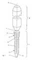
- Fig. 1 eine perspektivische Ansicht der Schraube mit integriertem Schraubendreher;
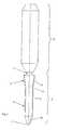
- Fig. 2 einen Längsschnitt durch die Schraube mit integriertem Schraubendreher; und
- Fig. 3 eine perspektivische Ansicht einer Knochenplatte zur Aufnahme einer Schraube nach Fig. 1.
- 1 is a perspective view of the screw with integrated screwdriver.
- 2 shows a longitudinal section through the screw with integrated screwdriver. and
- 3 is a perspective view of a bone plate for receiving a screw of FIG .. 1
Die in den Fig. 1 und 2 dargestellte Schraube 1 und der integrierte Schraubendreher 2 weisen eine gemeinsame Längsachse 6 auf. Die als Knochenschraube ausgebildete Schraube 1 weist eine Länge von 2,6 mm auf und besitzt einen Schraubenschaft 3 der Länge 1,3 mm mit einem Gewinde 4 und einen konischen Schraubenkopf 5 der Länge 1,1 mm mit Aussengewinde 8. Zwischen Schraubenschaft 3 und Schraubenkopf 5 ist ein Gewindefreistich 9 angeordnet. Das Gewinde 4 des Schraubenschaftes 3 ist mittels einer Nut 10 selbstschneidend ausgebildet. Der Schraubendreher 2 ist 4,9 mm lang und über eine Sollbruchstelle 7 koaxial mit dem Schraubenkopf 5 verbunden. Die Sollbruchstelle weist einen Durchmesser von 0,35 mm auf.The
Die Schraube 1 kann in die Plattenbohrung 13 der in Fig. 3 dargestellten Knochenplatte 12 eingeführt werden. Das zum Aussengewinde 8 der Schraube 1 korrespondierende Innengewinde 14 der Plattenbohrung 13 bewirkt eine winkelstabile Verankerung der Schraube 1 bezüglich der Knochenplatte 12. Das Innengewinde 14 und das dazu korrespondierende Aussengewinde 8 können auch mehrgängig, vorzugsweise zweigängig, ausgebildet sein.The
Claims (11)
- Screw (1) with an integrated screw driver (2), wherebyA) the screw (1) is provided with a threaded shaft (3) with thread (4), a screw head (5) and a longitudinal axis (6);B) the screw driver (2) is connected to the screw head (5) coaxially to the longitudinal axis (5) via a predetermined breaking point; andC) the screw head (5) conically enlarges towards the screw driver (2),
characterized in thatD) the screw head (5) is provided with an external thread (8); and thatE) an undercut (9) is disposed between the threaded shaft (3) and the screw head (5). - Screw (1) with an integrated screw driver (2) of claim 1, wherein the thread (4) of the threaded shaft (3) is self-cutting.
- Screw (1) with an integrated screw driver (2) of claim 1 or 2, wherein at its free end (11) a groove (10) is provided.
- Screw (1) with an integrated screw driver (2) of one of claims 1 to 3, wherein the screw (1) is a bone screw.
- Screw (1) with an integrated screw driver (2) of one of claims 1 to 4, wherein the screw (1) has a diameter of less than 2,0 mm.
- Screw (1) with an integrated screw driver (2) of claim 5, wherein the screw (1) has a diameter of less than 1,0 mm.
- Screw (1) with an integrated screw driver (2) of one of claims 1 to 6, wherein the predetermined breaking point (7) has a diameter which is smaller than the diameter of the undercut.
- Screw (1) with an integrated screw driver (2) of one of claims 1 to 7, wherein the predetermined breaking point (7) has a diameter from 60 to 82%, preferably 66 to 75% of the external diameter of the thread (4) of the threaded shaft (3).
- Screw (1) with an integrated screw driver (2) of one of claims 1 to 8, wherein the predetermined breaking point (7) has a diameter from 0,25 to 0,5 mm, preferably from 0,32 to 0,38 mm.
- Screw (1) with an integrated screw driver (2) of one of claims 1 to 9, wherein the external thread (8) of the threaded shaft (3) is a multiple thread, preferably a double thread.
- Bone plate (12) with at least one screw (1) according to one of the claims 1 to 10,
characterized in that
the bone plate is provided with at least one plate borehole (13) which is provided with an internal thread (14) corresponding to the external thread (4) of the threaded shaft (3).
Applications Claiming Priority (1)
| Application Number | Priority Date | Filing Date | Title |
|---|---|---|---|
| PCT/CH2003/000101WO2004072496A1 (en) | 2003-02-12 | 2003-02-12 | Screw comprising an integrated screwdriver |
Publications (2)
| Publication Number | Publication Date |
|---|---|
| EP1592893A1 EP1592893A1 (en) | 2005-11-09 |
| EP1592893B1true EP1592893B1 (en) | 2007-01-24 |
Family
ID=32855122
Family Applications (1)
| Application Number | Title | Priority Date | Filing Date |
|---|---|---|---|
| EP03700801ARevokedEP1592893B1 (en) | 2003-02-12 | 2003-02-12 | Screw comprising an integrated screwdriver |
Country Status (10)
| Country | Link |
|---|---|
| US (1) | US7316532B2 (en) |
| EP (1) | EP1592893B1 (en) |
| JP (1) | JP2006514233A (en) |
| AR (1) | AR043001A1 (en) |
| AT (1) | ATE352727T1 (en) |
| AU (1) | AU2003202403B2 (en) |
| CA (1) | CA2515899C (en) |
| DE (1) | DE50306417D1 (en) |
| ES (1) | ES2281620T3 (en) |
| WO (1) | WO2004072496A1 (en) |
Families Citing this family (47)
| Publication number | Priority date | Publication date | Assignee | Title |
|---|---|---|---|---|
| US7588575B2 (en)* | 2003-10-21 | 2009-09-15 | Innovative Spinal Technologies | Extension for use with stabilization systems for internal structures |
| US20060058796A1 (en) | 2004-09-14 | 2006-03-16 | Hartdegen Vernon R | Compression brace |
| US7569061B2 (en) | 2004-11-16 | 2009-08-04 | Innovative Spinal Technologies, Inc. | Off-axis anchor guidance system |
| ITMI20050195A1 (en)* | 2005-02-11 | 2006-08-12 | Aquila Luca Dell | PROSTHETIC INSTALLATION PARTICULARLY FOR ENDOOSSEA IMPLANTOLOGY AND FOR OSTEOINTEGRANT ORTHOPEDICS WITH IMMEDIATE AND DEFERRED LOAD |
| US20070162147A1 (en)* | 2005-12-21 | 2007-07-12 | Lewis Paul P P | Orthopaedic joint assembly with rigidly locked fastener, kit and associated method |
| US7946657B2 (en)* | 2006-08-11 | 2011-05-24 | Schlumberger Technology Corporation | Retention for an insert |
| US8007051B2 (en) | 2006-08-11 | 2011-08-30 | Schlumberger Technology Corporation | Shank assembly |
| DE112008000558T5 (en) | 2007-03-02 | 2010-01-07 | Biomet Microfixation, LLC, Jacksonville | Method for inserting a fastener |
| EP2843247B1 (en) | 2007-08-06 | 2022-02-16 | Nancy Tedeschi | Screw with breakaway and methods of using same |
| US8556556B2 (en) | 2007-08-06 | 2013-10-15 | Fbb Asset Management Limited Partnership | Screw with breakaway and methods of using the same |
| FR2922749B1 (en)* | 2007-10-25 | 2010-10-08 | D L P Sarl | THREADED HEAD SCREW FOR OSTHEOSYNTHESIS |
| FR2924918B1 (en)* | 2007-12-13 | 2010-09-03 | Alexandre Worcel | LOCKING BUSH FOR A OSTEOSYNTHESIS DEVICE AND OSTEOSYNTHESIS DEVICE COMPRISING SUCH A BUSHING |
| IT1392434B1 (en)* | 2008-12-23 | 2012-03-09 | Orthofix Srl | ORTHOPEDIC DEVICE TO ENCOURAGE THE RIGID FRACTURE OSTEOSYNTHESIS |
| FR2941859B1 (en) | 2009-02-09 | 2012-04-06 | Memometal Technologies | OSTEOSYNTHESIS SCREW. |
| US8701799B2 (en) | 2009-04-29 | 2014-04-22 | Schlumberger Technology Corporation | Drill bit cutter pocket restitution |
| DE102010016812A1 (en)* | 2009-06-08 | 2011-03-17 | Z.-Medical Gmbh & Co. Kg | bone screw |
| GB2485293A (en)* | 2009-10-02 | 2012-05-09 | Raptorgrip Ltd | Fastening pin |
| GB2474046B (en)* | 2009-10-02 | 2012-04-04 | Raptorgrip Ltd | A fastening assembly |
| US8523914B2 (en)* | 2010-01-28 | 2013-09-03 | Warsaw Orthopedic, Inc. | Bone anchor with predetermined break point and removal features |
| EP2928418A4 (en) | 2012-12-07 | 2016-12-21 | Providence Medical Tech Inc | Apparatus and method for bone screw deployment |
| US9743959B2 (en) | 2013-03-14 | 2017-08-29 | Atlas Spine, Inc. | Low profile spinal fixation system |
| US9458610B2 (en)* | 2014-06-10 | 2016-10-04 | Homewerks Worldwide, LLC | Plumbing connector |
| CN107847249A (en)* | 2015-05-11 | 2018-03-27 | 普罗维登斯医疗技术公司 | Bone screws and implant delivery apparatus |
| US10149710B2 (en)* | 2015-05-11 | 2018-12-11 | Providence Medical Technology, Inc. | Bone screw and implant delivery device |
| CN107835668A (en)* | 2015-05-11 | 2018-03-23 | 普罗维登斯医疗技术公司 | Method for being implanted into bone screws |
| US9974602B2 (en)* | 2015-05-27 | 2018-05-22 | Covidien Lp | Surgical instruments and devices and methods facilitating the manufacture of the same |
| US10531905B2 (en)* | 2016-04-19 | 2020-01-14 | Globus Medical, Inc. | Implantable compression screws |
| US10736681B2 (en) | 2016-11-01 | 2020-08-11 | Arthrosurface, Inc. | Devices, apparatuses, kits, and methods for osteotomy plates, guides, and cutters |
| US11806250B2 (en) | 2018-02-22 | 2023-11-07 | Warsaw Orthopedic, Inc. | Expandable spinal implant system and method of using same |
| US12239544B2 (en) | 2020-11-05 | 2025-03-04 | Warsaw Orthopedic, Inc. | Rhomboid shaped implants |
| US11963881B2 (en) | 2020-11-05 | 2024-04-23 | Warsaw Orthopedic, Inc. | Expandable inter-body device, system, and method |
| US12121453B2 (en) | 2020-11-05 | 2024-10-22 | Warsaw Orthopedic, Inc. | Dual wedge expandable implant with eyelets, system, and method of use |
| US11376134B1 (en) | 2020-11-05 | 2022-07-05 | Warsaw Orthopedic, Inc. | Dual expanding spinal implant, system, and method of use |
| US11517443B2 (en) | 2020-11-05 | 2022-12-06 | Warsaw Orthopedic, Inc. | Dual wedge expandable implant, system and method of use |
| US12171439B2 (en) | 2020-11-05 | 2024-12-24 | Warsaw Orthopedic, Inc. | Protected drill |
| US11395743B1 (en) | 2021-05-04 | 2022-07-26 | Warsaw Orthopedic, Inc. | Externally driven expandable interbody and related methods |
| US11833059B2 (en) | 2020-11-05 | 2023-12-05 | Warsaw Orthopedic, Inc. | Expandable inter-body device, expandable plate system, and associated methods |
| US11517363B2 (en) | 2020-11-05 | 2022-12-06 | Warsaw Orthopedic, Inc. | Screw driver and complimentary screws |
| US12318308B2 (en) | 2020-11-05 | 2025-06-03 | Warsaw Orthopedic, Inc. | Dual expandable inter-body device |
| US11638653B2 (en) | 2020-11-05 | 2023-05-02 | Warsaw Orthopedic, Inc. | Surgery instruments with a movable handle |
| TWI740776B (en)* | 2020-12-07 | 2021-09-21 | 財團法人工業技術研究院 | Low profile offset typespinal fusion device |
| US12268614B2 (en) | 2021-06-24 | 2025-04-08 | Warsaw Orthopedic, Inc. | Interbody implant with adjusting shims |
| US11612499B2 (en) | 2021-06-24 | 2023-03-28 | Warsaw Orthopedic, Inc. | Expandable interbody implant |
| WO2022271280A1 (en) | 2021-06-24 | 2022-12-29 | Warsaw Orthopedic, Inc. | Expandable interbody implant and corresponding surgical tool |
| US12295865B2 (en) | 2021-06-24 | 2025-05-13 | Warsaw Orthopedic, Inc. | Expandable interbody implant and corresponding inserter |
| US11850163B2 (en) | 2022-02-01 | 2023-12-26 | Warsaw Orthopedic, Inc. | Interbody implant with adjusting shims |
| FR3148900A1 (en)* | 2023-05-26 | 2024-11-29 | I.Ceram | JUMPER FOR OSTEOSYNTHESIS PIN |
Family Cites Families (35)
| Publication number | Priority date | Publication date | Assignee | Title |
|---|---|---|---|---|
| US2699774A (en)* | 1952-05-12 | 1955-01-18 | Livingston Herman Harrison | Bone pin locking device |
| FR2625430A1 (en)* | 1987-12-30 | 1989-07-07 | Guinounet Alain | LOCKING SCREW OF OSTEOSYNTHESIS PLATE AND METHOD OF MANUFACTURING SAME |
| US5120168A (en)* | 1990-12-06 | 1992-06-09 | Padula William V | Auto-torque, tamper-proof screw/bolt |
| US5501695A (en)* | 1992-05-27 | 1996-03-26 | The Anspach Effort, Inc. | Fastener for attaching objects to bones |
| DE4339804A1 (en) | 1993-11-23 | 1995-06-01 | Haerle Anton | Power transmission link for osteosynthesis work |
| FR2721819B1 (en)* | 1994-07-04 | 1996-10-04 | Amp Dev | SELF-DRILLING AND SELF-TAPPING ANKLE DEVICE WITH A SHRINKABLE END CAP, FOR LOCKING AN OSTEOSYNTHESIS PLATE OR COAPTING TWO BONE FRAGMENTS |
| CA2189744C (en)* | 1995-03-27 | 2003-09-16 | Gilbert Talos | Bone plate |
| US6193719B1 (en)* | 1995-08-24 | 2001-02-27 | Sofamor S.N.C. | Threaded clamping plug for interconnecting two implants of a spinal osteosynthesis instrumentation or other implants |
| US5743914A (en)* | 1996-06-06 | 1998-04-28 | Skiba; Jeffry B. | Bone screw |
| US6004349A (en)* | 1997-01-06 | 1999-12-21 | Jackson; Roger P. | Set screw for use with osteosynthesis apparatus |
| US6224596B1 (en)* | 1997-01-06 | 2001-05-01 | Roger P. Jackson | Set screw for use with osteosynthesis apparatus |
| FR2760628B1 (en)* | 1997-03-11 | 1999-11-26 | Biotech International | SCREW WITH THREADED HEAD FOR OSTEOSYNTHESIS OF BONE FRAGMENTS |
| US6056471A (en)* | 1998-06-11 | 2000-05-02 | Transpo Industries, Inc. | Multiple necked-down break-away coupling for highway or roadside appurtenances |
| US5971987A (en)* | 1998-09-18 | 1999-10-26 | Ethicon, Inc. | Biocompatible absorbable polymer fastener and driver for use in surgical procedures |
| US6214012B1 (en)* | 1998-11-13 | 2001-04-10 | Harrington Arthritis Research Center | Method and apparatus for delivering material to a desired location |
| ES2299238T3 (en)* | 1999-04-08 | 2008-05-16 | Orthofix S.R.L. | OSEO SCREW FOR EXTERNAL FIXERS. |
| US6290711B1 (en)* | 1999-08-13 | 2001-09-18 | Innovasive Devices, Inc. | Connector device and method for surgically joining and securing flexible tissue repair members |
| US6554852B1 (en)* | 1999-08-25 | 2003-04-29 | Michael A. Oberlander | Multi-anchor suture |
| CN1172634C (en)* | 1999-09-13 | 2004-10-27 | 库尔斯恩蒂斯股份公司 | Bone plating system |
| US6884244B1 (en)* | 2000-06-06 | 2005-04-26 | Roger P. Jackson | Removable medical implant closure for open headed implants |
| US20050267477A1 (en)* | 2000-06-06 | 2005-12-01 | Jackson Roger P | Removable medical implant closure |
| DK1294298T3 (en)* | 2000-06-26 | 2005-01-17 | Synthes Ag | Bone plate for osteosynthesis |
| US6726689B2 (en)* | 2002-09-06 | 2004-04-27 | Roger P. Jackson | Helical interlocking mating guide and advancement structure |
| US6997927B2 (en)* | 2000-12-08 | 2006-02-14 | Jackson Roger P | closure for rod receiving orthopedic implant having a pair of spaced apertures for removal |
| US6511481B2 (en)* | 2001-03-30 | 2003-01-28 | Triage Medical, Inc. | Method and apparatus for fixation of proximal femoral fractures |
| US7144413B2 (en)* | 2001-04-20 | 2006-12-05 | Synthes (U.S.A.) | Graft fixation system and method |
| ATE382298T1 (en)* | 2001-04-24 | 2008-01-15 | Coligne Ag | INSTRUMENTS FOR STABILIZING CERTAIN VERTEBRATES OF THE SPINE |
| AU783705B2 (en)* | 2001-07-02 | 2005-11-24 | Depuy France | Device for securing bits of bone together |
| FR2827503B1 (en)* | 2001-07-23 | 2003-10-24 | Macara Frederique | MODULAR RECONSTRUCTION COTYLE |
| US6783527B2 (en)* | 2001-10-30 | 2004-08-31 | Sdgi Holdings, Inc. | Flexible spinal stabilization system and method |
| US6723099B1 (en)* | 2001-11-08 | 2004-04-20 | Biomet, Inc. | Three sided tack for bone fixation |
| US6875215B2 (en)* | 2002-02-15 | 2005-04-05 | John Stanley Taras | Distraction pin for fracture fixation |
| US6955677B2 (en)* | 2002-10-15 | 2005-10-18 | The University Of North Carolina At Chapel Hill | Multi-angular fastening apparatus and method for surgical bone screw/plate systems |
| US20040243129A1 (en)* | 2003-05-28 | 2004-12-02 | Missoum Moumene | Double helical threaded bone screw |
| US20050245933A1 (en)* | 2004-05-03 | 2005-11-03 | Sevrain Lionel C | Multi coaxial screw system |
- 2003
- 2003-02-12EPEP03700801Apatent/EP1592893B1/ennot_activeRevoked
- 2003-02-12AUAU2003202403Apatent/AU2003202403B2/ennot_activeCeased
- 2003-02-12ATAT03700801Tpatent/ATE352727T1/enactive
- 2003-02-12CACA2515899Apatent/CA2515899C/ennot_activeExpired - Fee Related
- 2003-02-12WOPCT/CH2003/000101patent/WO2004072496A1/enactiveIP Right Grant
- 2003-02-12JPJP2004568071Apatent/JP2006514233A/enactivePending
- 2003-02-12DEDE50306417Tpatent/DE50306417D1/ennot_activeRevoked
- 2003-02-12ESES03700801Tpatent/ES2281620T3/ennot_activeExpired - Lifetime
- 2004
- 2004-02-02ARARP040100312Apatent/AR043001A1/ennot_activeApplication Discontinuation
- 2005
- 2005-08-03USUS11/197,717patent/US7316532B2/ennot_activeExpired - Fee Related
Also Published As
| Publication number | Publication date |
|---|---|
| ES2281620T3 (en) | 2007-10-01 |
| AR043001A1 (en) | 2005-07-13 |
| US7316532B2 (en) | 2008-01-08 |
| EP1592893A1 (en) | 2005-11-09 |
| ATE352727T1 (en) | 2007-02-15 |
| WO2004072496A1 (en) | 2004-08-26 |
| DE50306417D1 (en) | 2007-03-15 |
| AU2003202403B2 (en) | 2006-09-28 |
| US20060039772A1 (en) | 2006-02-23 |
| JP2006514233A (en) | 2006-04-27 |
| CA2515899A1 (en) | 2004-08-26 |
| CA2515899C (en) | 2011-08-23 |
| AU2003202403A1 (en) | 2004-09-06 |
Similar Documents
| Publication | Publication Date | Title |
|---|---|---|
| EP1592893B1 (en) | Screw comprising an integrated screwdriver | |
| EP2263584B1 (en) | Intramedullary nail with locking screw | |
| EP3177223B1 (en) | Screw with insertion post | |
| EP0639955B1 (en) | Screw for securing an intramedullary nail | |
| EP0657142B1 (en) | Element for osteosynthesis | |
| EP1175871B1 (en) | Locking nail | |
| DE29520312U1 (en) | Bone screw | |
| EP2799023A1 (en) | Screwdriver for bone screws | |
| WO2003047444A1 (en) | Bone screw | |
| EP1491294B1 (en) | Tool for the insertion of implant screws | |
| DE102020004179B4 (en) | Screw element and system consisting of a screwdriver and at least one such screw element | |
| DE3134120A1 (en) | CLAMPING DEVICE FOR AN OSTEOSYNTHESIS PLATE | |
| DE102005058879B4 (en) | Sound-activated dental instrument | |
| DE29611140U1 (en) | Arrangement of a screwdriver and a corresponding screw | |
| EP3372343B1 (en) | Assembly consisting of a torque-discharging support arm and a screwdriver | |
| EP3507510B1 (en) | Attachment element | |
| DE102017004043A1 (en) | Torque wrench with predefined torque limitation | |
| DE202007005829U1 (en) | Compression screw with wire element e.g. for mechanical connection of bone fractures, has longitudinal extending aligned shank which is divided into two parts, having thread | |
| EP0452623A2 (en) | Device for bending surgical screw connections | |
| DE20001865U1 (en) | Chuck for tool inserts, especially screwdriver bits | |
| DE102004041762A1 (en) | Tool to tap an inner thread within a deep core hole, in a workpiece, has a tap shaft extension inserted into the hole in front of the cutting head to give a self-centering action | |
| DE1911793C (en) | Emspindel clamping device for machine tools | |
| DE2530367C2 (en) | Torque wrench | |
| DE102010001680B3 (en) | Tool i.e. tap wrench, for use as holding device for e.g. threading die that forms threads in boreholes, has tool feeding unit and/or extension part attached to middle part or adjusting device, where tool feeding unit feeds working tool | |
| DE202006011466U1 (en) | Boring aid for profile bar, has opening, for holding borer, including cross section adapted to profile bar at one opposite end, so that aid is secured against rotation and opposite to profile bar in form-fit manner |
Legal Events
| Date | Code | Title | Description |
|---|---|---|---|
| PUAI | Public reference made under article 153(3) epc to a published international application that has entered the european phase | Free format text:ORIGINAL CODE: 0009012 | |
| 17P | Request for examination filed | Effective date:20050608 | |
| AK | Designated contracting states | Kind code of ref document:A1 Designated state(s):AT BE BG CH CY CZ DE DK EE ES FI FR GB GR HU IE IT LI LU MC NL PT SE SI SK TR | |
| AX | Request for extension of the european patent | Extension state:AL LT LV MK RO | |
| DAX | Request for extension of the european patent (deleted) | ||
| GRAP | Despatch of communication of intention to grant a patent | Free format text:ORIGINAL CODE: EPIDOSNIGR1 | |
| RAP1 | Party data changed (applicant data changed or rights of an application transferred) | Owner name:SYNTHES GMBH | |
| GRAS | Grant fee paid | Free format text:ORIGINAL CODE: EPIDOSNIGR3 | |
| GRAA | (expected) grant | Free format text:ORIGINAL CODE: 0009210 | |
| AK | Designated contracting states | Kind code of ref document:B1 Designated state(s):AT BE BG CH CY CZ DE DK EE ES FI FR GB GR HU IE IT LI LU MC NL PT SE SI SK TR | |
| PG25 | Lapsed in a contracting state [announced via postgrant information from national office to epo] | Ref country code:IE Free format text:LAPSE BECAUSE OF FAILURE TO SUBMIT A TRANSLATION OF THE DESCRIPTION OR TO PAY THE FEE WITHIN THE PRESCRIBED TIME-LIMIT Effective date:20070124 Ref country code:FI Free format text:LAPSE BECAUSE OF FAILURE TO SUBMIT A TRANSLATION OF THE DESCRIPTION OR TO PAY THE FEE WITHIN THE PRESCRIBED TIME-LIMIT Effective date:20070124 Ref country code:NL Free format text:LAPSE BECAUSE OF FAILURE TO SUBMIT A TRANSLATION OF THE DESCRIPTION OR TO PAY THE FEE WITHIN THE PRESCRIBED TIME-LIMIT Effective date:20070124 Ref country code:DK Free format text:LAPSE BECAUSE OF FAILURE TO SUBMIT A TRANSLATION OF THE DESCRIPTION OR TO PAY THE FEE WITHIN THE PRESCRIBED TIME-LIMIT Effective date:20070124 Ref country code:SI Free format text:LAPSE BECAUSE OF FAILURE TO SUBMIT A TRANSLATION OF THE DESCRIPTION OR TO PAY THE FEE WITHIN THE PRESCRIBED TIME-LIMIT Effective date:20070124 | |
| REG | Reference to a national code | Ref country code:GB Ref legal event code:FG4D Free format text:NOT ENGLISH | |
| REG | Reference to a national code | Ref country code:CH Ref legal event code:EP | |
| PG25 | Lapsed in a contracting state [announced via postgrant information from national office to epo] | Ref country code:MC Free format text:LAPSE BECAUSE OF NON-PAYMENT OF DUE FEES Effective date:20070228 | |
| REG | Reference to a national code | Ref country code:CH Ref legal event code:NV Representative=s name:DR. LUSUARDI AG | |
| REG | Reference to a national code | Ref country code:IE Ref legal event code:FG4D Free format text:LANGUAGE OF EP DOCUMENT: GERMAN | |
| GBT | Gb: translation of ep patent filed (gb section 77(6)(a)/1977) | Effective date:20070219 | |
| REF | Corresponds to: | Ref document number:50306417 Country of ref document:DE Date of ref document:20070315 Kind code of ref document:P | |
| REG | Reference to a national code | Ref country code:SE Ref legal event code:TRGR | |
| PG25 | Lapsed in a contracting state [announced via postgrant information from national office to epo] | Ref country code:BG Free format text:LAPSE BECAUSE OF EXPIRATION OF PROTECTION Effective date:20070425 | |
| ET | Fr: translation filed | ||
| PG25 | Lapsed in a contracting state [announced via postgrant information from national office to epo] | Ref country code:PT Free format text:LAPSE BECAUSE OF FAILURE TO SUBMIT A TRANSLATION OF THE DESCRIPTION OR TO PAY THE FEE WITHIN THE PRESCRIBED TIME-LIMIT Effective date:20070625 | |
| REG | Reference to a national code | Ref country code:HU Ref legal event code:AG4A Ref document number:E001496 Country of ref document:HU | |
| NLV1 | Nl: lapsed or annulled due to failure to fulfill the requirements of art. 29p and 29m of the patents act | ||
| REG | Reference to a national code | Ref country code:IE Ref legal event code:FD4D | |
| REG | Reference to a national code | Ref country code:ES Ref legal event code:FG2A Ref document number:2281620 Country of ref document:ES Kind code of ref document:T3 | |
| PLBI | Opposition filed | Free format text:ORIGINAL CODE: 0009260 | |
| PG25 | Lapsed in a contracting state [announced via postgrant information from national office to epo] | Ref country code:SK Free format text:LAPSE BECAUSE OF FAILURE TO SUBMIT A TRANSLATION OF THE DESCRIPTION OR TO PAY THE FEE WITHIN THE PRESCRIBED TIME-LIMIT Effective date:20070124 | |
| PLAX | Notice of opposition and request to file observation + time limit sent | Free format text:ORIGINAL CODE: EPIDOSNOBS2 | |
| 26 | Opposition filed | Opponent name:ORTHOFIX S.R.L. Effective date:20071024 | |
| BERE | Be: lapsed | Owner name:SYNTHES GMBH Effective date:20070228 | |
| PG25 | Lapsed in a contracting state [announced via postgrant information from national office to epo] | Ref country code:BE Free format text:LAPSE BECAUSE OF NON-PAYMENT OF DUE FEES Effective date:20070228 Ref country code:CZ Free format text:LAPSE BECAUSE OF FAILURE TO SUBMIT A TRANSLATION OF THE DESCRIPTION OR TO PAY THE FEE WITHIN THE PRESCRIBED TIME-LIMIT Effective date:20070124 | |
| PLBB | Reply of patent proprietor to notice(s) of opposition received | Free format text:ORIGINAL CODE: EPIDOSNOBS3 | |
| PG25 | Lapsed in a contracting state [announced via postgrant information from national office to epo] | Ref country code:GR Free format text:LAPSE BECAUSE OF FAILURE TO SUBMIT A TRANSLATION OF THE DESCRIPTION OR TO PAY THE FEE WITHIN THE PRESCRIBED TIME-LIMIT Effective date:20070425 | |
| PGFP | Annual fee paid to national office [announced via postgrant information from national office to epo] | Ref country code:HU Payment date:20080124 Year of fee payment:6 | |
| PG25 | Lapsed in a contracting state [announced via postgrant information from national office to epo] | Ref country code:EE Free format text:LAPSE BECAUSE OF FAILURE TO SUBMIT A TRANSLATION OF THE DESCRIPTION OR TO PAY THE FEE WITHIN THE PRESCRIBED TIME-LIMIT Effective date:20070124 | |
| PGFP | Annual fee paid to national office [announced via postgrant information from national office to epo] | Ref country code:AT Payment date:20090211 Year of fee payment:7 Ref country code:ES Payment date:20090317 Year of fee payment:7 | |
| PGFP | Annual fee paid to national office [announced via postgrant information from national office to epo] | Ref country code:DE Payment date:20090206 Year of fee payment:7 | |
| PGFP | Annual fee paid to national office [announced via postgrant information from national office to epo] | Ref country code:CH Payment date:20090213 Year of fee payment:7 | |
| PG25 | Lapsed in a contracting state [announced via postgrant information from national office to epo] | Ref country code:CY Free format text:LAPSE BECAUSE OF FAILURE TO SUBMIT A TRANSLATION OF THE DESCRIPTION OR TO PAY THE FEE WITHIN THE PRESCRIBED TIME-LIMIT Effective date:20070124 | |
| PG25 | Lapsed in a contracting state [announced via postgrant information from national office to epo] | Ref country code:LU Free format text:LAPSE BECAUSE OF NON-PAYMENT OF DUE FEES Effective date:20070212 | |
| PGFP | Annual fee paid to national office [announced via postgrant information from national office to epo] | Ref country code:IT Payment date:20090212 Year of fee payment:7 | |
| PG25 | Lapsed in a contracting state [announced via postgrant information from national office to epo] | Ref country code:TR Free format text:LAPSE BECAUSE OF FAILURE TO SUBMIT A TRANSLATION OF THE DESCRIPTION OR TO PAY THE FEE WITHIN THE PRESCRIBED TIME-LIMIT Effective date:20070124 | |
| PGFP | Annual fee paid to national office [announced via postgrant information from national office to epo] | Ref country code:FR Payment date:20090213 Year of fee payment:7 | |
| PG25 | Lapsed in a contracting state [announced via postgrant information from national office to epo] | Ref country code:HU Free format text:LAPSE BECAUSE OF NON-PAYMENT OF DUE FEES Effective date:20090213 | |
| RDAF | Communication despatched that patent is revoked | Free format text:ORIGINAL CODE: EPIDOSNREV1 | |
| PGFP | Annual fee paid to national office [announced via postgrant information from national office to epo] | Ref country code:SE Payment date:20091218 Year of fee payment:8 | |
| RDAG | Patent revoked | Free format text:ORIGINAL CODE: 0009271 | |
| STAA | Information on the status of an ep patent application or granted ep patent | Free format text:STATUS: PATENT REVOKED | |
| REG | Reference to a national code | Ref country code:CH Ref legal event code:PL | |
| 27W | Patent revoked | Effective date:20091217 | |
| GBPR | Gb: patent revoked under art. 102 of the ep convention designating the uk as contracting state | Effective date:20091217 | |
| REG | Reference to a national code | Ref country code:SE Ref legal event code:ECNC | |
| PGFP | Annual fee paid to national office [announced via postgrant information from national office to epo] | Ref country code:GB Payment date:20100202 Year of fee payment:8 | |
| PG25 | Lapsed in a contracting state [announced via postgrant information from national office to epo] | Ref country code:CH Free format text:LAPSE BECAUSE OF THE APPLICANT RENOUNCES Effective date:20070124 Ref country code:LI Free format text:LAPSE BECAUSE OF THE APPLICANT RENOUNCES Effective date:20070124 |