EP1592479B1 - Tachy lead system for septal placement - Google Patents
Tachy lead system for septal placementDownload PDFInfo
- Publication number
- EP1592479B1 EP1592479B1EP04705987AEP04705987AEP1592479B1EP 1592479 B1EP1592479 B1EP 1592479B1EP 04705987 AEP04705987 AEP 04705987AEP 04705987 AEP04705987 AEP 04705987AEP 1592479 B1EP1592479 B1EP 1592479B1
- Authority
- EP
- European Patent Office
- Prior art keywords
- lead assembly
- septum
- electrode
- neck
- distal end
- Prior art date
- Legal status (The legal status is an assumption and is not a legal conclusion. Google has not performed a legal analysis and makes no representation as to the accuracy of the status listed.)
- Expired - Lifetime
Links
- 241001385887TachysSpecies0.000titledescription2
- 239000004020conductorSubstances0.000claimsabstractdescription26
- 210000005241right ventricleAnatomy0.000claimsdescription17
- 239000000463materialSubstances0.000claimsdescription7
- LYCAIKOWRPUZTN-UHFFFAOYSA-NEthylene glycolChemical compoundOCCOLYCAIKOWRPUZTN-UHFFFAOYSA-N0.000claimsdescription4
- 239000003795chemical substances by applicationSubstances0.000claimsdescription4
- 229920001296polysiloxanePolymers0.000claimsdescription3
- 229920002635polyurethanePolymers0.000claimsdescription3
- 239000004814polyurethaneSubstances0.000claimsdescription3
- HTTJABKRGRZYRN-UHFFFAOYSA-NHeparinChemical compoundOC1C(NC(=O)C)C(O)OC(COS(O)(=O)=O)C1OC1C(OS(O)(=O)=O)C(O)C(OC2C(C(OS(O)(=O)=O)C(OC3C(C(O)C(O)C(O3)C(O)=O)OS(O)(=O)=O)C(CO)O2)NS(O)(=O)=O)C(C(O)=O)O1HTTJABKRGRZYRN-UHFFFAOYSA-N0.000claimsdescription2
- 229960002897heparinDrugs0.000claimsdescription2
- 229920000669heparinPolymers0.000claimsdescription2
- WGCNASOHLSPBMP-UHFFFAOYSA-NhydroxyacetaldehydeNatural productsOCC=OWGCNASOHLSPBMP-UHFFFAOYSA-N0.000claimsdescription2
- 230000004936stimulating effectEffects0.000claimsdescription2
- 208000007536ThrombosisDiseases0.000claims2
- 238000000034methodMethods0.000abstractdescription10
- 208000001871TachycardiaDiseases0.000description12
- 238000002560therapeutic procedureMethods0.000description10
- 210000001519tissueAnatomy0.000description10
- 238000003780insertionMethods0.000description6
- 230000037431insertionEffects0.000description6
- 238000013194cardioversionMethods0.000description4
- 210000002837heart atriumAnatomy0.000description4
- 230000006794tachycardiaEffects0.000description4
- 208000003734Supraventricular TachycardiaDiseases0.000description3
- 206010049447TachyarrhythmiaDiseases0.000description3
- 230000000747cardiac effectEffects0.000description3
- 210000005003heart tissueAnatomy0.000description3
- 230000033764rhythmic processEffects0.000description3
- 230000035939shockEffects0.000description3
- 230000002861ventricularEffects0.000description3
- 208000003663ventricular fibrillationDiseases0.000description3
- 206010047302ventricular tachycardiaDiseases0.000description3
- 229920000249biocompatible polymerPolymers0.000description2
- 206010061592cardiac fibrillationDiseases0.000description2
- 230000008602contractionEffects0.000description2
- 238000010586diagramMethods0.000description2
- 230000002600fibrillogenic effectEffects0.000description2
- 238000002513implantationMethods0.000description2
- 206010003658Atrial FibrillationDiseases0.000description1
- 208000007888Sinus TachycardiaDiseases0.000description1
- 206010047281Ventricular arrhythmiaDiseases0.000description1
- 230000002159abnormal effectEffects0.000description1
- 206010003119arrhythmiaDiseases0.000description1
- 230000006793arrhythmiaEffects0.000description1
- 230000000712assemblyEffects0.000description1
- 238000000429assemblyMethods0.000description1
- 206010003668atrial tachycardiaDiseases0.000description1
- 210000005242cardiac chamberAnatomy0.000description1
- 230000003176fibrotic effectEffects0.000description1
- 230000000004hemodynamic effectEffects0.000description1
- 230000001788irregularEffects0.000description1
- 229920002529medical grade siliconePolymers0.000description1
- 238000012544monitoring processMethods0.000description1
- 210000004165myocardiumAnatomy0.000description1
- 229920000642polymerPolymers0.000description1
- 239000004945silicone rubberSubstances0.000description1
- 210000001321subclavian veinAnatomy0.000description1
- 210000003462veinAnatomy0.000description1
Images


Classifications
- A—HUMAN NECESSITIES
- A61—MEDICAL OR VETERINARY SCIENCE; HYGIENE
- A61N—ELECTROTHERAPY; MAGNETOTHERAPY; RADIATION THERAPY; ULTRASOUND THERAPY
- A61N1/00—Electrotherapy; Circuits therefor
- A61N1/02—Details
- A61N1/04—Electrodes
- A61N1/05—Electrodes for implantation or insertion into the body, e.g. heart electrode
- A61N1/056—Transvascular endocardial electrode systems
- A61N1/057—Anchoring means; Means for fixing the head inside the heart
- A61N1/0573—Anchoring means; Means for fixing the head inside the heart chacterised by means penetrating the heart tissue, e.g. helix needle or hook
Definitions
- the present inventionrelates generally to a lead for stimulating or monitoring tissue. More particularly, it pertains to a lead that provides ventricular pacing and/or sensing.
- Tachyarrhythmiasare abnormal heart rhythms characterized by a rapid heart rate.
- tachyarrhythmiasinclude supraventricular tachycardias (SVT's) such as sinus tachycardia, atrial tachycardia, and atrial fibrillation.
- SVT'ssupraventricular tachycardias
- the most dangerous tachyarrhythmiasare ventricular tachycardia (VT) and ventricular fibrillation (VF).
- VTventricular tachycardia
- VFventricular fibrillation
- Cardioversion and defibrillationcan be used to terminate most tachyarrhythmias, including SVT's, VT, and VF.
- a class of cardiac rhythm management devicesknown as an implantable cardioverter/defibrillator (ICD) provides therapy by delivering a shock pulse to the heart, such as when the device detects fibrillation.
- ICDimplantable cardioverter/defibrillator
- ATPantitachycardia pacing
- the heartis paced using one or more pacing pulses in an effort to correct the tachycardia.
- Modem ICD'stypically have ATP capability so that ATP therapy is delivered to the heart when a tachycardia is detected, while a shock pulse is delivered when fibrillation occurs.
- cardioversion/defibrillationwill terminate tachycardia, it consumes a large amount of stored power from the battery and results in patient discomfort owing to the high voltage of the shock pulses. Therefore, it is desirable for the ICD to use ATP to terminate a tachyarrhythmia whenever possible.
- ICD'stypically include one or more leads that are implanted in or about the heart to reverse certain life threatening arrhythmias, or to stimulate contraction of the heart. Electrical energy is applied to the heart via electrodes on the leads to return the heart to normal rhythm.
- a typical cardiac pacing leadis positioned within one or more chambers of the heart such that the distal end of the lead is positioned in the ventricle or atrium through a subclavian vein, while the proximal end is attached to a pacemaker which is implanted subcutaneously.
- Some leadsalso include electrodes that operate as sensors to monitor the atrium and/or ventricle of the heart, and in some applications to deliver pacing pulses to the atrium or ventricle.
- One alternative cardiac pacing technique for treating tachyarrhythmiasinvolves placing a lead in the right ventricle to pace and/or defibrillate the high septal or outflow tract of a heart from the right ventricle.
- Studies in the literaturehave demonstrated hemodynamic superiority of right ventricular outflow tract and septal pacing compared with right ventricular apical pacing.
- US 6, 178, 355 and US 5, 871, 530each disclose a cardioversion/defibrillation lead comprising an elongated lead body.
- a centrally disposed lead extensionhaving a smaller diameter than the body and a plurality of elongated, un-insulated wire filaments surrounding the lead extension in a spaced relationship extend from the distal end of the body.
- a pace/sense helical screw-in electrodeadapted to be screwed into the myocardium at a selected site within a heart chamber is disposed at the distal end of the lead extension.
- the screw-in electrode and the wire filamentsare connected to respective conductors disposed within the lead extension and body.
- the wire filamentsform a distributed cardioversion/defibrillation electrode.
- the present inventionprovides a lead assembly as claimed in claim 1.
- the lead assemblyincludes a body with a proximal end and a distal end and at least one conductor disposed within the body.
- a distal electrodeis at the distal end of the body and is electrically coupled with at least one of the conductors.
- a first electrodeis on the body and is electrically coupled with at least one of the conductors.
- the lead assemblyfurther includes a septum-contacting drop down neck that is less stiff than the body. The neck is between the distal end of the body and the first electrode assembly.
- a fixation mechanism at the distal end of the bodyis capable of securing the lead assembly to a interventricular septum, or outflow tract, in a heart.
- the lead assemblycan be used to supply septal therapy to a patient that is suffering some heart ailment, such as a tachyarrhythmia.
- a cathetercan be used to insert the lead assembly into the right ventricle of a heart. Once the distal end of the lead assembly is attached to an upper portion of the septum, the catheter is removed.
- the relatively low stiffness of the neckallows the neck to drop down along the septum or right ventricle such that any electrodes on the neck and body of the lead assembly make good conforming contact with the septum and/or right ventricle.
- the benefits of better contact between electrodes that provide therapy to the heart and the tissue of the heartare known to those of ordinary skill in the art.
- the neckmay have a length between about 10mm and about 30mm.
- the lead assemblycan be used in a method which includes advancing the lead assembly using a catheter until the lead assembly is near tissue in a heart, such as a septum. The method further includes affixing a distal end of the body to the septum and removing the catheter to allow at least a portion of the neck to drop against the septum.
- the neck of the lead assemblyis less stiff than the body, the neck drops down against a septum in a heart once whatever insertion device that is used to attach the distal end of the lead assembly to the septum is removed from the heart.
- any number of different types of cardio therapiescan be provided to the septum, outflow tract and/or right ventricle (among other areas) of the heart.
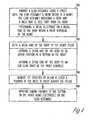
- Figure 1illustrates a lead assembly 100 that includes a body 115 and at least one conductor 150 contained within the body 115.
- the lead assembly 100is at least partially formed of a polymer, such as a medical grade silicone rubber for translumenal insertion and access within a living organism such as a patient.
- the conductor(s) 150may be any form of conductor, such as, but not limited to, a cable, coil or braided conductor.
- the body 115includes a proximal end 116 and a distal end 121.
- the lead assembly 100further includes a neck 120 that is less stiff than the body 115.
- the neck 120is between the distal end 121 and a first electrode 125 on the body 115.
- the neck 120has length between about 10mm and about 30mm.
- the first electrode 125is electrically coupled with the at least one conductor 150 at a section 117 adjacent to an end 122 of the neck 120.
- the first electrode 125is in the form of a shocking coil, although other types of electrodes may be used.
- the lead assembly 100includes a second electrode 135 that is also electrically coupled with the at least one conductor 150 and is positioned between the proximal end 116 of the body 115 and the first electrode 125.
- the second electrode 135is in the form of a shocking coil, although other types of electrodes may be used.
- the distal end 121 of the body 115includes a fixation mechanism, such as a helical coil 140, that is capable of securing the lead assembly 100 to tissue in a heart 190.
- a fixation mechanismsuch as a helical coil 140
- the helical coil 140may be positioned at an angle relative to the longitudinal axis of lead assembly 100 in order to facilitate attachment of the helical coil 140 to tissue of a heart 190, such as the septum 191 and/or the out flow tract 192 of a right ventricle 193 (see also FIGS. 5-7 ).
- a fixation mechanismsuch as a helical coil 140
- angle Ais between about 0 and about 90 degrees.
- the relatively low stiffness of the neck 120 on the lead assembly 100allows the lead assembly 100 to be used to apply septal therapy to a patient that is suffering some heart ailment, such as a tachyarrhythmia.
- the lead assembly 100is effective in applying such therapy because the neck 120 is adapted to drop against a septum 191 in a heart 190 once a catheter 199 that has been used to insert the lead assembly 100 into the septum 191 is withdrawn from the lead assembly 100.
- All, or some, portions of the body 115 and 120may be coated with an anti-thrombous agent, such as, but not limited to, heparin and polyethxlene glycol.
- an anti-thrombous agentsuch as, but not limited to, heparin and polyethxlene glycol.
- the anti-thrombous agentshelp to alleviate fibrotic attachment between the lead assembly 100 and heart tissue.
- a distal electrode 145is electrically coupled with the at least one conductor 150 and positioned at the distal end 121 of the neck 120.
- Distal electrode 145is in the form of a pacing electrode, although other types of electrodes may be used.
- a section 137 of the body 115 between the first electrode 125 and the second electrode 135is straight.
- section 137is pre-formed into an arc-shape to facilitate appropriate placement of electrodes assemblies 125, 135 against tissue, such as a septum 191 and/or right ventricle 193 within a heart 190 (see, e.g., FIG. 7 ).
- the neck 120is less stiff than the body 115 because the neck 120 has a cross-sectional area that is smaller than the cross-sectional area of the body 115.
- the distal end 121 of the body 115includes a section 129 having a cross-sectional area that is larger than the cross-sectional area of the neck 120.
- the cross-sectional area of the section 129is substantially the same as the cross-sectional area of the body 115 (see FIG. 3 ).
- FIG. 4shows a block diagram illustrating a method 300.
- the method 300includes advancing a lead assembly using a catheter until the lead assembly is near tissue in a heart, such as a septum, the lead assembly including a body and a neck that is less stiff than the body 310; affixing a distal end of the body to the heart tissue 320; and removing the catheter to allow at least a portion of the neck to drop against the tissue 330.
- the methodfurther includes applying cardio therapy to the septum in the heart using electrodes on the lead assembly 340.
- advancing a lead assembly using a catheter 199includes positioning the distal end of the body within a right ventricle of the heart.
- affixing a distal end of the body to the heartincludes affixing a distal end of the body to an upper portion of a septum and/or outflow tract in the heart.
- a catheter 199is used to guide the lead assembly 100.
- the catheter 199is manipulated to facilitate the insertion of the lead assembly 100 into and through a vein and then through an intracardiac valve.
- the distal end 121 of the lead body 115is advanced into the right ventricle 193 of a heart 190 until the distal end 121 is positioned near the septum 191, or outflow tract 192 adjoining the right ventricle 193, of heart 190.
- the distal end of the catheter 199is curved to facilitate insertion of the lead assembly 100 into an upper portion of the septum 191, or outflow tract 192.
- the distal end 121 of the body 115is affixed to the upper portion of the septum 191 or the out flow tract 192 (see FIG. 5 ) depending on factors considered by the physician at the time of implantation.
- the lead assembly 100is affixed to the heart 190 by manipulating the catheter 199 to maneuver the helical coil 140 into an upper portion of the septum 191 tissue within the heart 190.
- the catheter 199is removed such that the exposed portion of the neck 120 begins to drop against the septum 191 (see FIG. 6 ).
- first electrode 125 and/or the second electrode 135drop against the heart tissue (e.g., septum 191 and/or the bottom of right ventricle 193 as shown in FIG. 7 ).
- second electrode 135is spaced from first electrode 125 such that second electrode 135 is in a supraventricular location.
- the number and arrangement of electrodes on lead assembly 100 that drop against and engage the septum 191 and/or right ventricle 193 of heart 190depend on where the distal end 121 of the body 115 engages the heart 190, and the relative locations of any electrodes on the lead assembly 100 relative to the neck 120 and the distal end 121 of the body 115.
- the lead assembly 200similarly includes a body 215 and at least one conductor 250 (two conductors are shown in FIG. 9 ) contained within the body 215.
- the body 215includes a proximal end (not visible in FIGS. 8 and 9 ) and a distal end 221.
- a first electrode 225is electrically coupled with at least one of the conductors 250 and is positioned on the body 215.
- the lead assembly 200further includes a neck 220 that is less stiff than the body 215.
- the neck 220is between the distal end 221 of the body 215 and the first electrode 215.
- the first electrode 225is positioned on the body 215 at a section 217 that is adjacent to an end 222 of the neck 220.
- the lead assembly 200includes a second electrode 235 that is also electrically coupled with at least one of the conductors 250, and is positioned between the proximal end of the body 215 and the first electrode 225.
- the distal end 221 of the body 215includes a fixation mechanism, such as a helical coil 240, that is capable of securing the lead assembly 200 to tissue in a heart 190, such as a septum 191.
- a distal electrode 245is electrically coupled to at least one of the conductors 250 and is positioned at the distal end 221 of body 215.
- the neck 220is similarly less stiff than the body 215 because the neck 220 is made from a first material that is less stiff than a second material that forms the body 215.
- first material that forms the neck 220is silicone, polyurethane or other biocompatible polymers.
- second material that forms the body 215is silicone, polyurethane or other biocompatible polymers.
- the neck and body of the lead assemblymay be integral with one another or fabricated separately and joined together as long as the neck is less stiff than the body.
- the lead assemblyis meant to encompass all embodiments of a lead assembly that includes a neck and a body where the neck is less stiff than the body. Since the neck of the lead assembly less stiff than the body, the neck can drop against the septum when an insertion device that is used to attach the lead assembly to the septum is removed from the heart.
- the leads shown and described hereinare able to provide any number of different types of cardio therapies to a septum, outflow tract and/or right ventricle (among other areas) of a heart.
- the lead assembly 100may also be part of a system 194 for delivering electrical pulses to stimulate a heart and/or for receiving electrical pulses to monitor the heart.
- the system 194(see FIG. 3 ) includes a pulse generator 195 and/or signal sensor 197.
- the distal end 121is adapted for implantation within the heart of a patient and the proximal end 116 is connected directly or indirectly to a terminal connector that electrically connects the various electrodes and conductors within the lead body to the pulse generator 195 and/or signal sensor 197.
- the pulse generator 195 and/or signal sensor 197may be implanted pectorally, abdominally, or elsewhere within a patient.
Landscapes
- Health & Medical Sciences (AREA)
- Heart & Thoracic Surgery (AREA)
- Life Sciences & Earth Sciences (AREA)
- Animal Behavior & Ethology (AREA)
- Engineering & Computer Science (AREA)
- Biomedical Technology (AREA)
- Nuclear Medicine, Radiotherapy & Molecular Imaging (AREA)
- Radiology & Medical Imaging (AREA)
- Vascular Medicine (AREA)
- Cardiology (AREA)
- General Health & Medical Sciences (AREA)
- Public Health (AREA)
- Veterinary Medicine (AREA)
- Electrotherapy Devices (AREA)
- Surgical Instruments (AREA)
- Infusion, Injection, And Reservoir Apparatuses (AREA)
- External Artificial Organs (AREA)
Abstract
Description
- The present invention relates generally to a lead for stimulating or monitoring tissue. More particularly, it pertains to a lead that provides ventricular pacing and/or sensing.
- Tachyarrhythmias are abnormal heart rhythms characterized by a rapid heart rate. Examples of tachyarrhythmias include supraventricular tachycardias (SVT's) such as sinus tachycardia, atrial tachycardia, and atrial fibrillation. The most dangerous tachyarrhythmias, however, are ventricular tachycardia (VT) and ventricular fibrillation (VF). Ventricular rhythms typically result in rapid and irregular contraction of the ventricles out of electromechanical synchrony with the atria.
- Cardioversion and defibrillation can be used to terminate most tachyarrhythmias, including SVT's, VT, and VF. A class of cardiac rhythm management devices known as an implantable cardioverter/defibrillator (ICD) provides therapy by delivering a shock pulse to the heart, such as when the device detects fibrillation.
- Another type of electrical therapy for tachycardia is antitachycardia pacing (ATP). In ATP, the heart is paced using one or more pacing pulses in an effort to correct the tachycardia. Modem ICD's typically have ATP capability so that ATP therapy is delivered to the heart when a tachycardia is detected, while a shock pulse is delivered when fibrillation occurs.
- Although cardioversion/defibrillation will terminate tachycardia, it consumes a large amount of stored power from the battery and results in patient discomfort owing to the high voltage of the shock pulses. Therefore, it is desirable for the ICD to use ATP to terminate a tachyarrhythmia whenever possible.
- ICD's typically include one or more leads that are implanted in or about the heart to reverse certain life threatening arrhythmias, or to stimulate contraction of the heart. Electrical energy is applied to the heart via electrodes on the leads to return the heart to normal rhythm.
- A typical cardiac pacing lead is positioned within one or more chambers of the heart such that the distal end of the lead is positioned in the ventricle or atrium through a subclavian vein, while the proximal end is attached to a pacemaker which is implanted subcutaneously. Some leads also include electrodes that operate as sensors to monitor the atrium and/or ventricle of the heart, and in some applications to deliver pacing pulses to the atrium or ventricle.
- One alternative cardiac pacing technique for treating tachyarrhythmias involves placing a lead in the right ventricle to pace and/or defibrillate the high septal or outflow tract of a heart from the right ventricle. Studies in the literature have demonstrated hemodynamic superiority of right ventricular outflow tract and septal pacing compared with right ventricular apical pacing.
- Conventional leads are not designed for septal pacing. Accordingly, there is a need for a lead that is able to perform efficient septal pacing.
US 6, 178, 355 andUS 5, 871, 530 each disclose a cardioversion/defibrillation lead comprising an elongated lead body. A centrally disposed lead extension having a smaller diameter than the body and a plurality of elongated, un-insulated wire filaments surrounding the lead extension in a spaced relationship extend from the distal end of the body. A pace/sense helical screw-in electrode adapted to be screwed into the myocardium at a selected site within a heart chamber is disposed at the distal end of the lead extension. The screw-in electrode and the wire filaments are connected to respective conductors disposed within the lead extension and body. The wire filaments form a distributed cardioversion/defibrillation electrode.- The present invention provides a lead assembly as claimed in claim 1.
- Thus, the lead assembly includes a body with a proximal end and a distal end and at least one conductor disposed within the body. A distal electrode is at the distal end of the body and is electrically coupled with at least one of the conductors. A first electrode is on the body and is electrically coupled with at least one of the conductors. The lead assembly further includes a septum-contacting drop down neck that is less stiff than the body. The neck is between the distal end of the body and the first electrode assembly. A fixation mechanism at the distal end of the body is capable of securing the lead assembly to a interventricular septum, or outflow tract, in a heart.
- The lead assembly can be used to supply septal therapy to a patient that is suffering some heart ailment, such as a tachyarrhythmia. In some embodiments, a catheter can be used to insert the lead assembly into the right ventricle of a heart. Once the distal end of the lead assembly is attached to an upper portion of the septum, the catheter is removed.
- The relatively low stiffness of the neck allows the neck to drop down along the septum or right ventricle such that any electrodes on the neck and body of the lead assembly make good conforming contact with the septum and/or right ventricle. The benefits of better contact between electrodes that provide therapy to the heart and the tissue of the heart are known to those of ordinary skill in the art. The neck may have a length between about 10mm and about 30mm.
- The lead assembly can be used in a method which includes advancing the lead assembly using a catheter until the lead assembly is near tissue in a heart, such as a septum. The method further includes affixing a distal end of the body to the septum and removing the catheter to allow at least a portion of the neck to drop against the septum.
- Since the neck of the lead assembly is less stiff than the body, the neck drops down against a septum in a heart once whatever insertion device that is used to attach the distal end of the lead assembly to the septum is removed from the heart.
- Depending on the number, type and location of any electrodes on neck and body of the lead assembly, any number of different types of cardio therapies can be provided to the septum, outflow tract and/or right ventricle (among other areas) of the heart.
- These and other embodiments, aspects, advantages, and features of the present invention will be set forth in part in the description which follows, and in part will become apparent to those skilled in the art by reference to the following description of the invention and referenced drawings or by practice of the invention. The aspects, advantages, and features of the invention are realized and attained by means of the instrumentalities, procedures, and combinations particularly pointed out in the appended claims and their equivalents.
Figure 1 is a plan view illustrating a portion of a lead assembly.Figure 2 is an enlarged plan view illustrating the tip of the lead assembly shown inFigure 1 .Figure 3 is a plan view illustrating another embodiment of a lead assembly.Figure 4 is a block diagram illustrating a method in accordance with another embodiment of the invention.Figure 5 illustrates the lead assembly ofFigure 1 inserted into a heart using a catheter.Figure 6 illustrates the catheter partially removed from the lead assembly ofFigure 5 .Figure 7 illustrates the catheter removed from the lead assembly ofFigure 5 .Figure 8 is a plan view illustrating another embodiment of a lead assembly.Figure 9 is an enlarged section view illustrating a portion of the lead assembly ofFigure 8 .- In the following detailed description, reference is made to the accompanying drawings which show by way of illustration specific embodiments in which the invention may be practiced. These embodiments are described in sufficient detail to enable those skilled in the art to practice the invention. It is to be understood that other embodiments may be utilized and that structural changes made such that the following detailed description is not to be taken in a limiting sense.
Figure 1 illustrates alead assembly 100 that includes abody 115 and at least oneconductor 150 contained within thebody 115. Thelead assembly 100 is at least partially formed of a polymer, such as a medical grade silicone rubber for translumenal insertion and access within a living organism such as a patient. The conductor(s) 150 may be any form of conductor, such as, but not limited to, a cable, coil or braided conductor.- The
body 115 includes aproximal end 116 and adistal end 121. Thelead assembly 100 further includes aneck 120 that is less stiff than thebody 115. Theneck 120 is between thedistal end 121 and afirst electrode 125 on thebody 115. In some embodiments, theneck 120 has length between about 10mm and about 30mm. - In the illustrated example embodiment, the
first electrode 125 is electrically coupled with the at least oneconductor 150 at asection 117 adjacent to anend 122 of theneck 120. Thefirst electrode 125 is in the form of a shocking coil, although other types of electrodes may be used. - In some embodiments, the
lead assembly 100 includes asecond electrode 135 that is also electrically coupled with the at least oneconductor 150 and is positioned between theproximal end 116 of thebody 115 and thefirst electrode 125. Thesecond electrode 135 is in the form of a shocking coil, although other types of electrodes may be used. - The
distal end 121 of thebody 115 includes a fixation mechanism, such as ahelical coil 140, that is capable of securing thelead assembly 100 to tissue in aheart 190. Although thehelical coil 140 is shown inFIG. 1 as being substantially aligned with the longitudinal axis of theassembly 100, thehelical coil 140 may be positioned at an angle relative to the longitudinal axis oflead assembly 100 in order to facilitate attachment of thehelical coil 140 to tissue of aheart 190, such as theseptum 191 and/or theout flow tract 192 of a right ventricle 193 (see alsoFIGS. 5-7 ). One example is shown in phantom inFigure 2 where thehelical coil 140 is at an angle A relative to the longitudinal axis of thehelical coil 140. In some embodiments, angle A is between about 0 and about 90 degrees. - The relatively low stiffness of the
neck 120 on thelead assembly 100 allows thelead assembly 100 to be used to apply septal therapy to a patient that is suffering some heart ailment, such as a tachyarrhythmia. Thelead assembly 100 is effective in applying such therapy because theneck 120 is adapted to drop against aseptum 191 in aheart 190 once acatheter 199 that has been used to insert thelead assembly 100 into theseptum 191 is withdrawn from thelead assembly 100. - All, or some, portions of the
body lead assembly 100 and heart tissue. - In the illustrated example embodiment, a
distal electrode 145 is electrically coupled with the at least oneconductor 150 and positioned at thedistal end 121 of theneck 120.Distal electrode 145 is in the form of a pacing electrode, although other types of electrodes may be used. - In the embodiment illustrated in
Figure 1 , asection 137 of thebody 115 between thefirst electrode 125 and thesecond electrode 135 is straight. In the embodiment shown inFigure 3 ,section 137 is pre-formed into an arc-shape to facilitate appropriate placement ofelectrodes assemblies septum 191 and/orright ventricle 193 within a heart 190 (see, e.g.,FIG. 7 ). - In the embodiment illustrated in
Figure 1 , theneck 120 is less stiff than thebody 115 because theneck 120 has a cross-sectional area that is smaller than the cross-sectional area of thebody 115. In the example embodiment shown inFIG. 3 , thedistal end 121 of thebody 115 includes asection 129 having a cross-sectional area that is larger than the cross-sectional area of theneck 120. In some embodiments, the cross-sectional area of thesection 129 is substantially the same as the cross-sectional area of the body 115 (seeFIG. 3 ). FIG. 4 shows a block diagram illustrating a method 300. The method 300 includes advancing a lead assembly using a catheter until the lead assembly is near tissue in a heart, such as a septum, the lead assembly including a body and a neck that is less stiff than thebody 310; affixing a distal end of the body to theheart tissue 320; and removing the catheter to allow at least a portion of the neck to drop against thetissue 330. In some embodiments, the method further includes applying cardio therapy to the septum in the heart using electrodes on thelead assembly 340.- In some embodiments, advancing a lead assembly using a
catheter 199 includes positioning the distal end of the body within a right ventricle of the heart. In addition, affixing a distal end of the body to the heart includes affixing a distal end of the body to an upper portion of a septum and/or outflow tract in the heart. - The insertion of
lead assembly 100 withinheart 190 will be explained further with reference toFIGS. 5-7 . Acatheter 199 is used to guide thelead assembly 100. Thecatheter 199 is manipulated to facilitate the insertion of thelead assembly 100 into and through a vein and then through an intracardiac valve. Thedistal end 121 of thelead body 115 is advanced into theright ventricle 193 of aheart 190 until thedistal end 121 is positioned near theseptum 191, oroutflow tract 192 adjoining theright ventricle 193, ofheart 190. In some example embodiments, the distal end of thecatheter 199 is curved to facilitate insertion of thelead assembly 100 into an upper portion of theseptum 191, oroutflow tract 192. - The
distal end 121 of thebody 115 is affixed to the upper portion of theseptum 191 or the out flow tract 192 (seeFIG. 5 ) depending on factors considered by the physician at the time of implantation. As an example, thelead assembly 100 is affixed to theheart 190 by manipulating thecatheter 199 to maneuver thehelical coil 140 into an upper portion of theseptum 191 tissue within theheart 190. Once thedistal end 121 of thebody 115 is affixed, thecatheter 199 is removed such that the exposed portion of theneck 120 begins to drop against the septum 191 (seeFIG. 6 ). - In some embodiments, the
first electrode 125 and/or thesecond electrode 135 drop against the heart tissue (e.g.,septum 191 and/or the bottom ofright ventricle 193 as shown inFIG. 7 ). In other embodiments,second electrode 135 is spaced fromfirst electrode 125 such thatsecond electrode 135 is in a supraventricular location. The number and arrangement of electrodes onlead assembly 100 that drop against and engage theseptum 191 and/orright ventricle 193 ofheart 190 depend on where thedistal end 121 of thebody 115 engages theheart 190, and the relative locations of any electrodes on thelead assembly 100 relative to theneck 120 and thedistal end 121 of thebody 115. - Another
lead assembly 200 is shown inFIGS. 8 and 9 . Thelead assembly 200 similarly includes abody 215 and at least one conductor 250 (two conductors are shown inFIG. 9 ) contained within thebody 215. Thebody 215 includes a proximal end (not visible inFIGS. 8 and 9 ) and adistal end 221. Afirst electrode 225 is electrically coupled with at least one of theconductors 250 and is positioned on thebody 215. - The
lead assembly 200 further includes aneck 220 that is less stiff than thebody 215. Theneck 220 is between thedistal end 221 of thebody 215 and thefirst electrode 215. Thefirst electrode 225 is positioned on thebody 215 at asection 217 that is adjacent to anend 222 of theneck 220. - In some embodiments, the
lead assembly 200 includes asecond electrode 235 that is also electrically coupled with at least one of theconductors 250, and is positioned between the proximal end of thebody 215 and thefirst electrode 225. - The
distal end 221 of thebody 215 includes a fixation mechanism, such as ahelical coil 240, that is capable of securing thelead assembly 200 to tissue in aheart 190, such as aseptum 191. Adistal electrode 245 is electrically coupled to at least one of theconductors 250 and is positioned at thedistal end 221 ofbody 215. - In the example embodiment illustrated in
FIGS. 8 and 9 , theneck 220 is similarly less stiff than thebody 215 because theneck 220 is made from a first material that is less stiff than a second material that forms thebody 215. One example of the first material that forms theneck 220 is silicone, polyurethane or other biocompatible polymers. In addition, one example of the second material that forms thebody 215 is silicone, polyurethane or other biocompatible polymers. In any embodiment, the neck and body of the lead assembly may be integral with one another or fabricated separately and joined together as long as the neck is less stiff than the body. - It should be noted that the lead assembly is meant to encompass all embodiments of a lead assembly that includes a neck and a body where the neck is less stiff than the body. Since the neck of the lead assembly less stiff than the body, the neck can drop against the septum when an insertion device that is used to attach the lead assembly to the septum is removed from the heart. The leads shown and described herein are able to provide any number of different types of cardio therapies to a septum, outflow tract and/or right ventricle (among other areas) of a heart.
- The
lead assembly 100 may also be part of asystem 194 for delivering electrical pulses to stimulate a heart and/or for receiving electrical pulses to monitor the heart. The system 194 (seeFIG. 3 ) includes apulse generator 195 and/orsignal sensor 197. As discussed above, thedistal end 121 is adapted for implantation within the heart of a patient and theproximal end 116 is connected directly or indirectly to a terminal connector that electrically connects the various electrodes and conductors within the lead body to thepulse generator 195 and/orsignal sensor 197. Thepulse generator 195 and/orsignal sensor 197 may be implanted pectorally, abdominally, or elsewhere within a patient. - It is to be understood that the above description is intended to be illustrative, and not restrictive. For instance, the leads described above include, but are not limited to, tachy or brady leads. It should be noted that features of the various above-described embodiments may be interchanged to form additional combinations. Many other embodiments will be apparent to those of skill in the art upon reviewing the above description. The scope of the invention should be determined with reference to the appended claims.
Claims (21)
- A lead assembly (100, 200) for stimulating a heart (190) from one or both of an outflow tract (192) or an interventricular septum (191) comprising:a body (115, 215) including a proximal end (116) and a distal end (121, 221);at least one conductor (150, 250) disposed within the body;a distal electrode (145, 245) at the distal end of the body, the distal electrode electrically coupled with at least one of the conductors;a first electrode (125, 225) on the body, the first electrode electrically coupled with at least one of the conductors;a septum-contacting drop down neck (120, 220) between the distal end of the body and the first electrode, the neck being less stiff than the body thereby allowing the neck to drop down along the septum or right ventricle such that any electrodes on the neck and body of the lead assembly make good conforming contact with the septum and/or right ventricle; anda fixation mechanism at the distal end of the body, the fixation mechanism capable of securing the distal end to the outflow tract or the septum.
- The lead assembly of claim 1, wherein the septum-contacting drop down neck drops against the septum such that the distal electrode and the first electrode engage the septum.
- The lead assembly of any of claims 1 or 2, further comprising a second electrode (135, 235) coupled with at least one of the conductors, the second electrode positioned between the proximal end of the body and the first electrode.
- The lead assembly of claim 3, wherein the septum-contacting drop down neck drops against the septum such that the second electrode engages a bottom portion of a right ventricle (193).
- The lead assembly of claim 3, wherein a section (137) of the body between the first electrode and the second electrode is arc-shaped.
- The lead assembly of any of claims 1-5, wherein the fixation mechanism is a helical coil (140, 240).
- The lead assembly of claim 6, wherein the helical coil is aligned with a longitudinal axis of the body.
- The lead assembly of claim 6, wherein the helical coil is at an angle (A) between about 0 and 90 degrees relative to a longitudinal axis of the body.
- The lead assembly of any of claims 1-8, wherein the septum-contacting drop down neck has a length between about 10mm and about 30 mm.
- The lead assembly of any of claims 1-9, wherein the body has a first cross-sectional area and the septum-contacting drop down neck has a second cross-sectional area that is smaller than the first cross-sectional area of the body.
- The lead assembly of claim 10, wherein the distal end of the septum-contacting drop down neck includes a section (129) that has a third cross-sectional area which is different than the second cross-sectional area.
- The lead assembly of claim 11, wherein the third cross-sectional area of the section at the distal end of the septum-contacting drop down neck is substantially the same size as the first cross-sectional area of the body.
- The lead assembly of any of claims 1-12, wherein the body is made of a first material and the neck is made of a second material.
- The lead assembly of claim 13, wherein the first material is silicone or polyurethane.
- The lead assembly of any of claims 1-14, wherein the body is coated with an anti-thrombus agent.
- The lead assembly of claim 15, wherein the anti-thrombus agent is one or a combination of heparin or polyethxlene glycol.
- The lead assembly of any of claims 1-16, wherein the first electrode is a shocking coil.
- The lead assembly of any of claims 1-17, wherein the distal electrode is a sensing electrode.
- The lead assembly of any of claims 1-18, further comprising a pulse generator (195) electrically coupled to at least one of the conductors.
- The lead assembly of any of claims 1-19, further comprising a signal sensor (197) electrically coupled to at least one of the conductors.
- The lead assembly of any of claims 1-20, wherein the septum-contacting drop down neck drops against one or both of the outflow tract or the septum upon the removal of a guide catheter (199).
Applications Claiming Priority (3)
| Application Number | Priority Date | Filing Date | Title |
|---|---|---|---|
| US10/352,546US20040147994A1 (en) | 2003-01-28 | 2003-01-28 | Tachy lead system optimized for septal placement |
| US352546 | 2003-01-28 | ||
| PCT/US2004/002220WO2004067089A1 (en) | 2003-01-28 | 2004-01-28 | Tachy lead system for septal placement |
Publications (2)
| Publication Number | Publication Date |
|---|---|
| EP1592479A1 EP1592479A1 (en) | 2005-11-09 |
| EP1592479B1true EP1592479B1 (en) | 2009-07-29 |
Family
ID=32735998
Family Applications (1)
| Application Number | Title | Priority Date | Filing Date |
|---|---|---|---|
| EP04705987AExpired - LifetimeEP1592479B1 (en) | 2003-01-28 | 2004-01-28 | Tachy lead system for septal placement |
Country Status (6)
| Country | Link |
|---|---|
| US (1) | US20040147994A1 (en) |
| EP (1) | EP1592479B1 (en) |
| JP (1) | JP4716516B2 (en) |
| AT (1) | ATE437670T1 (en) |
| DE (1) | DE602004022256D1 (en) |
| WO (1) | WO2004067089A1 (en) |
Families Citing this family (14)
| Publication number | Priority date | Publication date | Assignee | Title |
|---|---|---|---|---|
| US7392094B2 (en) | 2002-12-19 | 2008-06-24 | Cardiac Pacemakers, Inc. | Implantable lead for septal placement of pacing electrodes |
| US7729782B2 (en)* | 2005-11-15 | 2010-06-01 | Medtronic, Inc. | Delivery catheter |
| US7647124B2 (en) | 2005-11-15 | 2010-01-12 | Medtronic, Inc. | Delivery catheter |
| US7801622B2 (en)* | 2006-03-30 | 2010-09-21 | Medtronic, Inc. | Medical electrical lead and delivery system |
| JP5154692B2 (en)* | 2008-04-15 | 2013-02-27 | カーディアック ペースメイカーズ, インコーポレイテッド | His bundle stimulation system |
| CN102365308B (en) | 2009-01-12 | 2014-03-12 | 马萨诸塞大学卢维尔分校 | Polyisobutylene-based polyurethanes |
| US8529934B2 (en) | 2009-08-21 | 2013-09-10 | Boston Scientific Scimed, Inc. | Crosslinkable polyisobutylene-based polymers and medical devices containing the same |
| US8374704B2 (en)* | 2009-09-02 | 2013-02-12 | Cardiac Pacemakers, Inc. | Polyisobutylene urethane, urea and urethane/urea copolymers and medical leads containing the same |
| US8644952B2 (en) | 2009-09-02 | 2014-02-04 | Cardiac Pacemakers, Inc. | Medical devices including polyisobutylene based polymers and derivatives thereof |
| WO2014081916A2 (en) | 2012-11-21 | 2014-05-30 | University Of Massachusetts | High strength polyisobutylene polyurethanes |
| EP3525669A4 (en) | 2016-10-17 | 2020-05-13 | Atrium Health | Devices, systems, and methods for treating cardiac arrhythmias |
| CN110382568B (en) | 2017-03-07 | 2022-03-04 | 心脏起搏器股份公司 | Hydroboration/oxidation of allyl-terminated polyisobutylenes |
| US10835638B2 (en) | 2017-08-17 | 2020-11-17 | Cardiac Pacemakers, Inc. | Photocrosslinked polymers for enhanced durability |
| EP3740253B1 (en) | 2018-01-17 | 2023-08-16 | Cardiac Pacemakers, Inc. | End-capped polyisobutylene polyurethane |
Family Cites Families (45)
| Publication number | Priority date | Publication date | Assignee | Title |
|---|---|---|---|---|
| US4332259A (en)* | 1979-09-19 | 1982-06-01 | Mccorkle Jr Charles E | Intravenous channel cardiac electrode and lead assembly and method |
| US4458677A (en)* | 1979-09-19 | 1984-07-10 | Mccorkle Jr Charles E | Intravenous channel cardiac electrode and lead assembly and method |
| US4759378A (en)* | 1982-10-14 | 1988-07-26 | American Hospital Supply Corporation | Flexible tip cardiac pacing catheter |
| US4641656A (en)* | 1985-06-20 | 1987-02-10 | Medtronic, Inc. | Cardioversion and defibrillation lead method |
| US4957111A (en)* | 1985-09-13 | 1990-09-18 | Pfizer Hospital Products Group, Inc. | Method of using a doppler catheter |
| US5014696A (en)* | 1987-01-14 | 1991-05-14 | Medtronic, Inc. | Endocardial defibrillation electrode system |
| US5226427A (en)* | 1988-04-28 | 1993-07-13 | Research Medical Inc. | Removable stylet for retrograde cardioplegia catheter and methods for use |
| US4991603A (en)* | 1989-10-30 | 1991-02-12 | Siemens-Pacesetter, Inc. | Transvenously placed defibrillation leads via an inferior vena cava access site and method of use |
| US5044375A (en)* | 1989-12-08 | 1991-09-03 | Cardiac Pacemakers, Inc. | Unitary intravascular defibrillating catheter with separate bipolar sensing |
| US5107834A (en)* | 1991-01-30 | 1992-04-28 | Cardiac Pacemakers, Inc. | Low energy multiple shock defibrillation/cardioversion discharge technique and electrode configuration |
| US5176137A (en)* | 1991-03-01 | 1993-01-05 | Medtronic, Inc. | Apparatus for discrimination of stable and unstable ventricular tachycardia and for treatment thereof |
| US5353800A (en)* | 1992-12-11 | 1994-10-11 | Medtronic, Inc. | Implantable pressure sensor lead |
| US5387233A (en)* | 1993-01-11 | 1995-02-07 | Incontrol, Inc. | Intravenous cardiac lead with improved fixation and method |
| IT1271458B (en)* | 1993-03-08 | 1997-05-28 | Leonardo Cammilli | SEQUENTIAL CARDIAC STIMULATION (DDD) SYSTEM WITH THE USE OF A SINGLE LEAD INSERTED THROUGH THE CORONARY BREAST. |
| US5423806A (en)* | 1993-10-01 | 1995-06-13 | Medtronic, Inc. | Laser extractor for an implanted object |
| US5409469A (en)* | 1993-11-04 | 1995-04-25 | Medtronic, Inc. | Introducer system having kink resistant splittable sheath |
| SE9304031D0 (en)* | 1993-12-03 | 1993-12-03 | Siemens Elema Ab | electrode System |
| US5476500A (en)* | 1993-12-20 | 1995-12-19 | Ventritex, Inc. | Endocardial lead system with defibrillation electrode fixation |
| US5447519A (en)* | 1994-03-19 | 1995-09-05 | Medtronic, Inc. | Method and apparatus for discrimination of monomorphic and polymorphic arrhythmias and for treatment thereof |
| US5476498A (en)* | 1994-08-15 | 1995-12-19 | Incontrol, Inc. | Coronary sinus channel lead and method |
| US5639276A (en)* | 1994-09-23 | 1997-06-17 | Rapid Development Systems, Inc. | Device for use in right ventricular placement and method for using same |
| US5643580A (en)* | 1994-10-17 | 1997-07-01 | Surface Genesis, Inc. | Biocompatible coating, medical device using the same and methods |
| US5634936A (en)* | 1995-02-06 | 1997-06-03 | Scimed Life Systems, Inc. | Device for closing a septal defect |
| US5683447A (en)* | 1995-12-19 | 1997-11-04 | Ventritex, Inc. | Lead with septal defibrillation and pacing electrodes |
| US5772693A (en)* | 1996-02-09 | 1998-06-30 | Cardiac Control Systems, Inc. | Single preformed catheter configuration for a dual-chamber pacemaker system |
| US5843117A (en)* | 1996-02-14 | 1998-12-01 | Inflow Dynamics Inc. | Implantable vascular and endoluminal stents and process of fabricating the same |
| US5713867A (en)* | 1996-04-29 | 1998-02-03 | Medtronic, Inc. | Introducer system having kink resistant splittable sheath |
| US5728140A (en)* | 1996-06-17 | 1998-03-17 | Cardiac Pacemakers, Inc. | Method for evoking capture of left ventricle using transeptal pacing lead |
| US5803928A (en)* | 1997-01-24 | 1998-09-08 | Cardiac Pacemakers, Inc. | Side access "over the wire" pacing lead |
| US5843141A (en)* | 1997-04-25 | 1998-12-01 | Medronic, Inc. | Medical lead connector system |
| US6038472A (en)* | 1997-04-29 | 2000-03-14 | Medtronic, Inc. | Implantable defibrillator and lead system |
| US6490474B1 (en)* | 1997-08-01 | 2002-12-03 | Cardiac Pathways Corporation | System and method for electrode localization using ultrasound |
| US5922014A (en)* | 1997-09-02 | 1999-07-13 | Medtronic, Inc. | Single pass lead and method of use |
| US6070104A (en)* | 1997-11-28 | 2000-05-30 | Medtronic, Inc. | Medical electrical right atrium and coronary sinus lead |
| US6006137A (en)* | 1998-03-06 | 1999-12-21 | Medtronic, Inc. | Method for single elecrode bi-atrial pacing |
| US6055457A (en)* | 1998-03-13 | 2000-04-25 | Medtronic, Inc. | Single pass A-V lead with active fixation device |
| US6256541B1 (en)* | 1998-04-17 | 2001-07-03 | Cardiac Pacemakers, Inc. | Endocardial lead having defibrillation and sensing electrodes with septal anchoring |
| US6463323B1 (en)* | 1998-11-12 | 2002-10-08 | Em Vascular, Inc. | Electrically mediated angiogenesis |
| US6161029A (en)* | 1999-03-08 | 2000-12-12 | Medtronic, Inc. | Apparatus and method for fixing electrodes in a blood vessel |
| US6129750A (en)* | 1999-03-23 | 2000-10-10 | Cardiac Pacemakers, Inc. | Fixation mechanism for a coronary venous pacing lead |
| US6549812B1 (en)* | 1999-11-29 | 2003-04-15 | Medtronic, Inc. | Medical electrical lead having bending stiffness which increase in the distal direction |
| DE10011572A1 (en)* | 2000-03-02 | 2001-09-06 | Biotronik Mess & Therapieg | Electrode arrangement |
| JP4251767B2 (en)* | 2000-10-23 | 2009-04-08 | テルモ株式会社 | Living body electrode lead |
| US6643546B2 (en)* | 2001-02-13 | 2003-11-04 | Quetzal Biomedical, Inc. | Multi-electrode apparatus and method for treatment of congestive heart failure |
| AR047851A1 (en)* | 2004-12-20 | 2006-03-01 | Giniger Alberto German | A NEW MARCAPASOS THAT RESTORES OR PRESERVES THE PHYSIOLOGICAL ELECTRIC DRIVING OF THE HEART AND A METHOD OF APPLICATION |
- 2003
- 2003-01-28USUS10/352,546patent/US20040147994A1/ennot_activeAbandoned
- 2004
- 2004-01-28ATAT04705987Tpatent/ATE437670T1/ennot_activeIP Right Cessation
- 2004-01-28JPJP2006503065Apatent/JP4716516B2/ennot_activeExpired - Fee Related
- 2004-01-28EPEP04705987Apatent/EP1592479B1/ennot_activeExpired - Lifetime
- 2004-01-28WOPCT/US2004/002220patent/WO2004067089A1/enactiveApplication Filing
- 2004-01-28DEDE602004022256Tpatent/DE602004022256D1/ennot_activeExpired - Lifetime
Also Published As
| Publication number | Publication date |
|---|---|
| EP1592479A1 (en) | 2005-11-09 |
| WO2004067089A1 (en) | 2004-08-12 |
| DE602004022256D1 (en) | 2009-09-10 |
| US20040147994A1 (en) | 2004-07-29 |
| JP2006515795A (en) | 2006-06-08 |
| ATE437670T1 (en) | 2009-08-15 |
| JP4716516B2 (en) | 2011-07-06 |
Similar Documents
| Publication | Publication Date | Title |
|---|---|---|
| US7349736B2 (en) | Active housing dual lead assembly | |
| US6157862A (en) | Shaped multiple electrode lead for implantable device | |
| US5755761A (en) | Atrial pacing catheter and method having multiple electrodes in the right atrium and coronary sinus | |
| US6141594A (en) | Single pass lead and system with active and passive fixation elements | |
| EP1363697B1 (en) | Coronary veins lead for pacing or sensing | |
| US5423865A (en) | Electrode system for a defibrillator | |
| US6246906B1 (en) | System and method for treating atrial arrhythmias | |
| US8372055B2 (en) | Method of using a deflectable subselecting catheter | |
| EP1592479B1 (en) | Tachy lead system for septal placement | |
| US5383908A (en) | Defibrillation system having innominate vein electrode and method for its use | |
| JP2005523786A (en) | Implantable automatic defibrillator with subcutaneous electrode | |
| US20230381496A1 (en) | Implantable medical device lead with modular electrode | |
| US9327133B2 (en) | Implantable medical device | |
| US20230381500A1 (en) | Method and implantable medical device for reducing defibrillation impedance | |
| US7079892B2 (en) | System and method of cardiac stimulation at oblique vein | |
| WO2025133669A1 (en) | Multi-level electrode | |
| AU6680496A (en) | Implantable pharmacological defibrillator system | |
| WO1997004834A2 (en) | Implantable pharmacological defibrillator system |
Legal Events
| Date | Code | Title | Description |
|---|---|---|---|
| PUAI | Public reference made under article 153(3) epc to a published international application that has entered the european phase | Free format text:ORIGINAL CODE: 0009012 | |
| 17P | Request for examination filed | Effective date:20050818 | |
| AK | Designated contracting states | Kind code of ref document:A1 Designated state(s):AT BE BG CH CY CZ DE DK EE ES FI FR GB GR HU IE IT LI LU MC NL PT RO SE SI SK TR | |
| AX | Request for extension of the european patent | Extension state:AL LT LV MK | |
| DAX | Request for extension of the european patent (deleted) | ||
| 17Q | First examination report despatched | Effective date:20060303 | |
| RIC1 | Information provided on ipc code assigned before grant | Ipc:A61N 1/05 20060101AFI20081201BHEP | |
| GRAP | Despatch of communication of intention to grant a patent | Free format text:ORIGINAL CODE: EPIDOSNIGR1 | |
| GRAS | Grant fee paid | Free format text:ORIGINAL CODE: EPIDOSNIGR3 | |
| GRAA | (expected) grant | Free format text:ORIGINAL CODE: 0009210 | |
| AK | Designated contracting states | Kind code of ref document:B1 Designated state(s):AT BE BG CH CY CZ DE DK EE ES FI FR GB GR HU IE IT LI LU MC NL PT RO SE SI SK TR | |
| REG | Reference to a national code | Ref country code:GB Ref legal event code:FG4D | |
| REG | Reference to a national code | Ref country code:CH Ref legal event code:EP | |
| REG | Reference to a national code | Ref country code:IE Ref legal event code:FG4D | |
| REF | Corresponds to: | Ref document number:602004022256 Country of ref document:DE Date of ref document:20090910 Kind code of ref document:P | |
| NLV1 | Nl: lapsed or annulled due to failure to fulfill the requirements of art. 29p and 29m of the patents act | ||
| PG25 | Lapsed in a contracting state [announced via postgrant information from national office to epo] | Ref country code:FI Free format text:LAPSE BECAUSE OF FAILURE TO SUBMIT A TRANSLATION OF THE DESCRIPTION OR TO PAY THE FEE WITHIN THE PRESCRIBED TIME-LIMIT Effective date:20090729 Ref country code:ES Free format text:LAPSE BECAUSE OF FAILURE TO SUBMIT A TRANSLATION OF THE DESCRIPTION OR TO PAY THE FEE WITHIN THE PRESCRIBED TIME-LIMIT Effective date:20091109 Ref country code:AT Free format text:LAPSE BECAUSE OF FAILURE TO SUBMIT A TRANSLATION OF THE DESCRIPTION OR TO PAY THE FEE WITHIN THE PRESCRIBED TIME-LIMIT Effective date:20090729 Ref country code:SE Free format text:LAPSE BECAUSE OF FAILURE TO SUBMIT A TRANSLATION OF THE DESCRIPTION OR TO PAY THE FEE WITHIN THE PRESCRIBED TIME-LIMIT Effective date:20090729 | |
| PG25 | Lapsed in a contracting state [announced via postgrant information from national office to epo] | Ref country code:NL Free format text:LAPSE BECAUSE OF FAILURE TO SUBMIT A TRANSLATION OF THE DESCRIPTION OR TO PAY THE FEE WITHIN THE PRESCRIBED TIME-LIMIT Effective date:20090729 Ref country code:SI Free format text:LAPSE BECAUSE OF FAILURE TO SUBMIT A TRANSLATION OF THE DESCRIPTION OR TO PAY THE FEE WITHIN THE PRESCRIBED TIME-LIMIT Effective date:20090729 | |
| PG25 | Lapsed in a contracting state [announced via postgrant information from national office to epo] | Ref country code:BG Free format text:LAPSE BECAUSE OF FAILURE TO SUBMIT A TRANSLATION OF THE DESCRIPTION OR TO PAY THE FEE WITHIN THE PRESCRIBED TIME-LIMIT Effective date:20091029 Ref country code:PT Free format text:LAPSE BECAUSE OF FAILURE TO SUBMIT A TRANSLATION OF THE DESCRIPTION OR TO PAY THE FEE WITHIN THE PRESCRIBED TIME-LIMIT Effective date:20091129 | |
| PG25 | Lapsed in a contracting state [announced via postgrant information from national office to epo] | Ref country code:DK Free format text:LAPSE BECAUSE OF FAILURE TO SUBMIT A TRANSLATION OF THE DESCRIPTION OR TO PAY THE FEE WITHIN THE PRESCRIBED TIME-LIMIT Effective date:20090729 Ref country code:RO Free format text:LAPSE BECAUSE OF FAILURE TO SUBMIT A TRANSLATION OF THE DESCRIPTION OR TO PAY THE FEE WITHIN THE PRESCRIBED TIME-LIMIT Effective date:20090729 Ref country code:CZ Free format text:LAPSE BECAUSE OF FAILURE TO SUBMIT A TRANSLATION OF THE DESCRIPTION OR TO PAY THE FEE WITHIN THE PRESCRIBED TIME-LIMIT Effective date:20090729 Ref country code:EE Free format text:LAPSE BECAUSE OF FAILURE TO SUBMIT A TRANSLATION OF THE DESCRIPTION OR TO PAY THE FEE WITHIN THE PRESCRIBED TIME-LIMIT Effective date:20090729 | |
| PG25 | Lapsed in a contracting state [announced via postgrant information from national office to epo] | Ref country code:BE Free format text:LAPSE BECAUSE OF FAILURE TO SUBMIT A TRANSLATION OF THE DESCRIPTION OR TO PAY THE FEE WITHIN THE PRESCRIBED TIME-LIMIT Effective date:20090729 Ref country code:SK Free format text:LAPSE BECAUSE OF FAILURE TO SUBMIT A TRANSLATION OF THE DESCRIPTION OR TO PAY THE FEE WITHIN THE PRESCRIBED TIME-LIMIT Effective date:20090729 | |
| PLBE | No opposition filed within time limit | Free format text:ORIGINAL CODE: 0009261 | |
| STAA | Information on the status of an ep patent application or granted ep patent | Free format text:STATUS: NO OPPOSITION FILED WITHIN TIME LIMIT | |
| 26N | No opposition filed | Effective date:20100503 | |
| PG25 | Lapsed in a contracting state [announced via postgrant information from national office to epo] | Ref country code:MC Free format text:LAPSE BECAUSE OF NON-PAYMENT OF DUE FEES Effective date:20100131 | |
| REG | Reference to a national code | Ref country code:CH Ref legal event code:PL | |
| GBPC | Gb: european patent ceased through non-payment of renewal fee | Effective date:20100128 | |
| REG | Reference to a national code | Ref country code:FR Ref legal event code:ST Effective date:20100930 | |
| PG25 | Lapsed in a contracting state [announced via postgrant information from national office to epo] | Ref country code:CH Free format text:LAPSE BECAUSE OF NON-PAYMENT OF DUE FEES Effective date:20100131 Ref country code:LI Free format text:LAPSE BECAUSE OF NON-PAYMENT OF DUE FEES Effective date:20100131 Ref country code:GR Free format text:LAPSE BECAUSE OF FAILURE TO SUBMIT A TRANSLATION OF THE DESCRIPTION OR TO PAY THE FEE WITHIN THE PRESCRIBED TIME-LIMIT Effective date:20091030 Ref country code:FR Free format text:LAPSE BECAUSE OF NON-PAYMENT OF DUE FEES Effective date:20100201 | |
| PG25 | Lapsed in a contracting state [announced via postgrant information from national office to epo] | Ref country code:GB Free format text:LAPSE BECAUSE OF NON-PAYMENT OF DUE FEES Effective date:20100128 | |
| PG25 | Lapsed in a contracting state [announced via postgrant information from national office to epo] | Ref country code:IE Free format text:LAPSE BECAUSE OF NON-PAYMENT OF DUE FEES Effective date:20100128 | |
| PG25 | Lapsed in a contracting state [announced via postgrant information from national office to epo] | Ref country code:CY Free format text:LAPSE BECAUSE OF FAILURE TO SUBMIT A TRANSLATION OF THE DESCRIPTION OR TO PAY THE FEE WITHIN THE PRESCRIBED TIME-LIMIT Effective date:20090729 | |
| PG25 | Lapsed in a contracting state [announced via postgrant information from national office to epo] | Ref country code:LU Free format text:LAPSE BECAUSE OF NON-PAYMENT OF DUE FEES Effective date:20100128 Ref country code:HU Free format text:LAPSE BECAUSE OF FAILURE TO SUBMIT A TRANSLATION OF THE DESCRIPTION OR TO PAY THE FEE WITHIN THE PRESCRIBED TIME-LIMIT Effective date:20100130 | |
| PG25 | Lapsed in a contracting state [announced via postgrant information from national office to epo] | Ref country code:TR Free format text:LAPSE BECAUSE OF FAILURE TO SUBMIT A TRANSLATION OF THE DESCRIPTION OR TO PAY THE FEE WITHIN THE PRESCRIBED TIME-LIMIT Effective date:20090729 | |
| PGFP | Annual fee paid to national office [announced via postgrant information from national office to epo] | Ref country code:DE Payment date:20140122 Year of fee payment:11 | |
| PGFP | Annual fee paid to national office [announced via postgrant information from national office to epo] | Ref country code:IT Payment date:20140114 Year of fee payment:11 | |
| REG | Reference to a national code | Ref country code:DE Ref legal event code:R082 Ref document number:602004022256 Country of ref document:DE Representative=s name:PFENNING MEINIG & PARTNER GBR, DE | |
| REG | Reference to a national code | Ref country code:DE Ref legal event code:R119 Ref document number:602004022256 Country of ref document:DE | |
| PG25 | Lapsed in a contracting state [announced via postgrant information from national office to epo] | Ref country code:DE Free format text:LAPSE BECAUSE OF NON-PAYMENT OF DUE FEES Effective date:20150801 | |
| PG25 | Lapsed in a contracting state [announced via postgrant information from national office to epo] | Ref country code:IT Free format text:LAPSE BECAUSE OF NON-PAYMENT OF DUE FEES Effective date:20150128 |