EP1591963B1 - Adaptive quantisation of a depth map - Google Patents
Adaptive quantisation of a depth mapDownload PDFInfo
- Publication number
- EP1591963B1 EP1591963B1EP04252510AEP04252510AEP1591963B1EP 1591963 B1EP1591963 B1EP 1591963B1EP 04252510 AEP04252510 AEP 04252510AEP 04252510 AEP04252510 AEP 04252510AEP 1591963 B1EP1591963 B1EP 1591963B1
- Authority
- EP
- European Patent Office
- Prior art keywords
- histogram
- bin
- images
- depth map
- bins
- Prior art date
- Legal status (The legal status is an assumption and is not a legal conclusion. Google has not performed a legal analysis and makes no representation as to the accuracy of the status listed.)
- Expired - Lifetime
Links
Images


Classifications
- G—PHYSICS
- G06—COMPUTING OR CALCULATING; COUNTING
- G06T—IMAGE DATA PROCESSING OR GENERATION, IN GENERAL
- G06T9/00—Image coding
- G06T9/008—Vector quantisation
- G—PHYSICS
- G06—COMPUTING OR CALCULATING; COUNTING
- G06T—IMAGE DATA PROCESSING OR GENERATION, IN GENERAL
- G06T9/00—Image coding
- G06T9/007—Transform coding, e.g. discrete cosine transform
- H—ELECTRICITY
- H04—ELECTRIC COMMUNICATION TECHNIQUE
- H04N—PICTORIAL COMMUNICATION, e.g. TELEVISION
- H04N13/00—Stereoscopic video systems; Multi-view video systems; Details thereof
- H04N13/10—Processing, recording or transmission of stereoscopic or multi-view image signals
- H04N13/106—Processing image signals
- H04N13/128—Adjusting depth or disparity
- H—ELECTRICITY
- H04—ELECTRIC COMMUNICATION TECHNIQUE
- H04N—PICTORIAL COMMUNICATION, e.g. TELEVISION
- H04N19/00—Methods or arrangements for coding, decoding, compressing or decompressing digital video signals
- H04N19/10—Methods or arrangements for coding, decoding, compressing or decompressing digital video signals using adaptive coding
- H04N19/102—Methods or arrangements for coding, decoding, compressing or decompressing digital video signals using adaptive coding characterised by the element, parameter or selection affected or controlled by the adaptive coding
- H04N19/124—Quantisation
- H04N19/126—Details of normalisation or weighting functions, e.g. normalisation matrices or variable uniform quantisers
- H—ELECTRICITY
- H04—ELECTRIC COMMUNICATION TECHNIQUE
- H04N—PICTORIAL COMMUNICATION, e.g. TELEVISION
- H04N19/00—Methods or arrangements for coding, decoding, compressing or decompressing digital video signals
- H04N19/50—Methods or arrangements for coding, decoding, compressing or decompressing digital video signals using predictive coding
- H04N19/597—Methods or arrangements for coding, decoding, compressing or decompressing digital video signals using predictive coding specially adapted for multi-view video sequence encoding
- H—ELECTRICITY
- H04—ELECTRIC COMMUNICATION TECHNIQUE
- H04N—PICTORIAL COMMUNICATION, e.g. TELEVISION
- H04N13/00—Stereoscopic video systems; Multi-view video systems; Details thereof
- H04N13/20—Image signal generators
- H04N13/204—Image signal generators using stereoscopic image cameras
- H04N13/207—Image signal generators using stereoscopic image cameras using a single 2D image sensor
- H04N13/221—Image signal generators using stereoscopic image cameras using a single 2D image sensor using the relative movement between cameras and objects
Definitions
- a depth mapis an image with "per-pixel" depth information, giving the distance of each captured 3D point from the centre of the camera. This can be captured with an IR range camera or obtained through various means of image processing tools from a 3D content-based image (referring to depth map evaluated from the estimated disparity field or by using motion analysis in monoscopic images).
- the input depth mapmay have either floating point or integer number representation. For the integer number representation, for instance, an n-bit depth image will store depth information as n-bit grey-values, with the grey-level 0 defining the furthest value and the grey-level 2 n -1 defining the closest value.
- An object-based coderis described in D. Tzovaras, N. Grammalidis, and M. G. Strintzis, "Object-based coding of stereo image sequences using joint 3D motion/disparity compensation", IEEE Trans. On Video Technology, Vol.7, No.2, April 1997 , for the coding of the left channel of a 3D stereo image sequence.
- the 3D motion parameters(three translational and three rotational) are used for coding of depth maps as well as intensity images.
- the depth mapis coded and transmitted using a method for isolated depth maps.
- a prediction of the current depth mapis formed using the previous in time depth map along with the 3D motion parameters.
- the MPEG-4 standardis proposed for the transmission of the depth maps offering sufficient freedom within this standard to provide extra depth enhancement layers.
- the MACMultiple Auxiliary Components
- VOPvideo object plane
- ROIRegion of Interest
- JPEG-2000provides the means of selectively encoding ROI's using the maxshift.
- the coefficients belonging to the ROIare shifted such that their bit-planes do not overlap with the non-ROI coefficients.
- the ROI coefficientscan be implicitly identified from their shifted values, and thus no shape information needs to be explicitly transmitted to the decoder.
- US 6,055,330describes a video compression technique, which make use of three-dimensional shape information as part of the video segmentation and compression processes.
- This methodidentifies separate objects using depth information corresponding to a field or frame of video sequence. It provides an object segmentation circuit for receiving depth information of a frame or video sequence; identifies one or more separate objects within the frame and converts the depth information into an object map. Each object map is associated to each depth region by a masking circuit. In one of the approaches the objects are identified from the histogram of the depth information. Thus the number of pixels with a predetermined depth values are selected based on a threshold value used and a clipped histogram is generated.
- the new histogramis scanned to find the boundaries of n regions with n different threshold depth values and a variable step quantization circuit is used to quantize the depth information in order to generate the object map. Once identified, the objects are sent as input to the MPEG-4 encoder.
- US 6,104,837proposes a method for depth compression, which identifies the patches of pixels in the depth image with all pixels in the patch having the same or similar depth values.
- the algorithminvolves a merging procedure in order to create the final sized patches and exclude areas where it is known that no depth data will be required.
- patches of adjoining pixels of the imageare determined within a first predetermined range and a first common depth value is assigned to all pixels of the patch.
- a first common depth valueis assigned to all pixels of the patch.
- the corresponding number of pixelsis calculated and, the smallest patches are eliminated by re-assigning the nearest existing discrete depth value to them. This step is repeated until a predetermined number N of discrete depth values remains.
- linear quantizationa method of mapping the pixels from n-bit to m-bit (with n>m) representation, using a linear function, where m is for example the number of bits used by a standard codec. This function is defined as division by a constant.
- F xx / 2 m 2 n
- linear de-quantizationas a method of mapping the pixels from m-bit to n-bit (with n>m) representation using a linear function. This function is defined as multiplication by a constant.
- F xx * / 2 m 2 n
- the pixels mapping process from 16-bit data to 8-bit datais graphically illustrated in Fig. 1 .
- the initial 16-bit per pixel representationcorresponds to 2 16 grey level values, which are to be grouped into 256 equally spaced bins. For each of the 256 bins the width of the bin will be the same, while the number of pixels in each bin varies.
- a new grey level valueis allocated for all the pixels belonging to each of the 256 bins.
- the new grey level valueis calculated as the average bin value in the 8-bit histogram multiplied by 256.
- n-bit depth mapis first quantized to 8-bit to be compatible to a standard encoder. After encoding/decoding process, the depth data is dequantized back to n-bit representation.
- the function used for reshaping in this exampleis the quadratic function from (1).
- k ⁇ak + 1 - a ⁇ k 2
- k' valuesare encoded using the JPEG-2000 algorithm after scaling this floating point number to a 16-bit number.
- the inventionaddresses the problem of quantization of the depth data accompanying a video or graphics image prior to coding in order to exploit the distribution of objects in the scene, especially non-linear distribution. For example, some depth values may not appear at all in the scene while others need to be more finely quantized than would be the case with linear quantization of the whole scene.
- Our approachtakes into account the depth image as a whole without performing explicit segmentation of the objects against the background.
- the inventionalso addresses the problem of de-quantization of depth data consisting of re-mapping the pixels back from m-bit to n-bit (with n>m) representation.
- a non-linear piecewise functionis derived from the distribution of the depth data accompanying a video or graphics image, in order to create a suitable mapping to lower precision acceptable by a standard video encoder.
- the non-linear mappingtakes into account the actual depth values occurring in the scene and creates a suitable mapping relation to displacement and extraction.
- the inventive ideaalso addresses non-linear de-quantization following the encoding/decoding process, where the m-bit depth data is re-mapped to n-bit data (with n>m) using an appropriate reconstruction value calculated for each bin.
- the approach to estimationis to assign more quantization cells to the regions with high histogram count of depth values and approximate the resulting mapping function with higher accuracy.
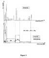
- FIG. 3An example of the general block diagram of the non-linear quantization from 16-bit data to 8-bit data is given in Fig. 3 .
- the resulting 256 binswill be non-equally spaced containing the same number of pixels and having different width.
- a 16-bit depth histogramnamely H16 is produced.
- This histogramcontains 2 16 numbers of bins, each bin having the width equal to 1. This is equal to the number of grey levels possible to be encountered in a 16-bit data representation.
- H16is a representation of the total number of pixels for each intensity level in the 16-bit image.
- H8represents the 8-bit histogram to be derived from the 16-bit depth map.
- the process of distributing (mapping) pixels from the H16 to H8is carried out by adding up the consecutive values of H i until the threshold value is reached. If the checked non-zero value H i is greater then the threshold, all the pixels H i fill the corresponding bin B m in the 8-bit histogram. Moreover, at this stage, an overflow is calculated to keep an indication of the number of pixels overfloating the threshold value. This overflow value is taken into account when filling the next bin where it represents the starting value in calculating the number of pixels in this current bin. This means that, a counter variable used to count the number of pixels in the current bin will start at a non-zero value, specifically the value of overflow. This is a reference value only in order to keep the statistic of the pixels in the image, since no transfer of pixels takes place when the threshold value is overflown.
- the PSNRmay be better for linear quantization. Further examination suggested that this may be related to situations where the width of a bin is extremely large and where there may be a small number of isolated pixels situated at the edge of the bins. These particular bins are far from the weighted value of the bin. Since the weighted value represents the estimated value when re-mapping back to 16-bit, those isolated pixels may introduce an error in the reconstructed 16-bit image. The further away from the weighted value, the larger the error is.
- a threshold valuehas been used to limit the size of a bin in the NL quantizer.
- a representative valueis calculated, that can be either the average value of the bin or the weighted average value of the bin, which will be used in the de-quantization process.
- a second embodimentinvolves non-linear quantization with pixels clustering.
- the size of the non-linear binsis decided by minimizing an error measure in each bin.
- pixelswill be grouped (clustered) into bins based on error measurement.
- the erroris calculated as a sum of squared differences between the pixels in the bin and the representative weighted value of the bin.
- the array of weighted values calculated in the quantization stagewill be used in the de-quantization process for re-mapping from 8-bit to n-bit (with n>8) depth data.
- FIG. 5A flow diagram illustrating this method is shown in Figure 5 .
- the PSNR values after re-mappingshow that for all frames in both video sequences tested the PSNR values corresponding to the NL quantizer are higher than their Linear equivalent.
- An average gain of 2.5 dBis obtained by using the NL quantizer when limiting the width of the bin.
- an algorithm based on Max-Lloyd quantizer for optimal scalar quantizationcan be used ( see David S. Taubman and Michael W. Marcellin, "JPEG2000: Image Compression Fundamentals, Standards and Practice ". Boston, Kluwer Academic Publishers, 2002(pp. 98-101 ).
- the quantizertakes an n-bit depth-map ( x ) as input and maps it to 256-level ( L i corresponding to each bin B i ) so that distortion D is minimised;
- L 256 D⁇ ( x - Q x ⁇ ) 2 f x ⁇ dx
- the quantizeris optimum when it satisfies two conditions:
- mappingin the spatial domain
- One possible mechanism for this in an MPEG-like codecwould be to pre-define a set of mappings in the picture header and switch between them on the macroblock level.
- the non-linear quantization/de-quantization method proposed hererelies on multiple histogram calculation, one for each frame/field in the video sequence.
- an averaged histogramcan be calculated with a corresponding array of averaged weighted values.
- all the frames/fields in the video sequencewould refer to the averaged weighted vector in the de-quantization process.
- Another approachwould consider an adjusted histogram, which means that we only have to calculate the histogram corresponding to the first frame/field in the video sequence, and adjust the histogram of the next frame based on differences between the frames.
- one possible implementationwould be to initialise the Lloyd-Max quantizer described above to the previous quantization map. Based on an appropriate distortion criterion value (e.g. MSE of corresponding reconstruction values or quantization boundaries), the system would decide whether an update of the mapping is necessary and send it differentially if necessary.
- an appropriate distortion criterion valuee.g. MSE of corresponding reconstruction values or quantization boundaries
- the non-linear quantization of the depth map proposed hereis meant to exploit the nonlinear relation between depth and displacement and, consequently the reconstructed picture. It can be combined with the method proposed by Krishnamurty et al. in R. Krishnamurthy, B. Chai, H. Tao and S. Sethuraman, "Compression and transmission of depth maps for image-based rendering", Proc. of International Conference on Image processing (ICIP'2001), Thessaloniki, Greece, Oct. 2001 , based on reshaping of the dynamic range of depth maps by use of a scaling function.
- imagemeans a whole image or a region of an image, except where apparent from the context.
- a region of an imagecan mean the whole image.
- An imageincludes a frame or a field, and relates to a still image or an image in a sequence of images such as a film or video, or in a related group of images.
- the imagemay be a grayscale or colour image, or another type of multi-spectral image, for example, IR, UV or other electromagnetic image, or an acoustic image etc.
- the inventioncan be implemented for example in a computer system, with suitable software and/or hardware modifications, or similarly an encoder and/or decoder system. Aspects of the invention can be provided in software and/or hardware form, or in an application-specific apparatus or application-specific modules can be provided, such as chips. Components of a system in an apparatus according to an embodiment of the invention may be provided remotely from other components.
Landscapes
- Engineering & Computer Science (AREA)
- Multimedia (AREA)
- Signal Processing (AREA)
- Physics & Mathematics (AREA)
- General Physics & Mathematics (AREA)
- Theoretical Computer Science (AREA)
- Discrete Mathematics (AREA)
- Compression Or Coding Systems Of Tv Signals (AREA)
- Compression Of Band Width Or Redundancy In Fax (AREA)
- Facsimile Image Signal Circuits (AREA)
- Compression, Expansion, Code Conversion, And Decoders (AREA)
Description
- This invention addresses efficient quantization of depth map data before the encoding. A depth map is an image with "per-pixel" depth information, giving the distance of each captured 3D point from the centre of the camera. This can be captured with an IR range camera or obtained through various means of image processing tools from a 3D content-based image (referring to depth map evaluated from the estimated disparity field or by using motion analysis in monoscopic images). The input depth map may have either floating point or integer number representation. For the integer number representation, for instance, an n-bit depth image will store depth information as n-bit grey-values, with the grey-
level 0 defining the furthest value and the grey-level 2n-1 defining the closest value. - Various methods have been proposed for efficient encoding and transmission of 8-bit depth data associated to still images or a moving image sequence.
- Two methods for coding isolated depth map are described inD. Tzovaras, N. Grammalidis, and M. G. Strintzis, "Disparity field and depth map coding for multiview 3D image generation", Image Communication, Vol. 11, No.3, January 1998. In the first, depth maps are quantized and coded as if they were intensity images (I-frames) using the JPEG coding technique. In the second method, a wireframe model is adapted to the depth map information. Initially the wireframe model is fit in each B x B block of the object area. The block size is reduced successively as to obtain an adequate approximation of the depth information in this area.
- Coding of depth map sequences is achieved inD. Tzovaras, N. Grammalidis, and M. G. Strintzis, "Disparity field and depth map coding for multiview 3D image generation", Image Communication, Vol. 11, No.3, January 1998, by using a 2D motion compensation method. In this case, an MPEG-like scheme for the coding of depth maps can be employed.
- An object-based coder is described inD. Tzovaras, N. Grammalidis, and M. G. Strintzis, "Object-based coding of stereo image sequences using joint 3D motion/disparity compensation", IEEE Trans. On Video Technology, Vol.7, No.2, April 1997, for the coding of the left channel of a 3D stereo image sequence. The 3D motion parameters (three translational and three rotational) are used for coding of depth maps as well as intensity images. For the first frame of the sequence, the depth map is coded and transmitted using a method for isolated depth maps. For the rest of the frames, a prediction of the current depth map is formed using the previous in time depth map along with the 3D motion parameters.
- InA. Alatan and L. Onural, "Joint estimation and optimum encoding of depth field for 3D object-based video coding", Proc. IEEE ICIP 96, Lausanne, Switzerland, September 1996, vol. II, pp. 871-874 andA. Alatan and L. Onural, "Estimation of depth fields suitable for video compression based on 3D structure and motion of objects", IEEE Transactions on Image Processing, no. 6, June 1998, a method for coding the depth field of the moving objects in the scene is discussed. Using two intensity frames and 3D motion parameters as inputs, an encoded depth field can be obtained by jointly minimizing a distortion criteria and a bit-rate measure.
- Finally, the MPEG-4 standard is proposed for the transmission of the depth maps offering sufficient freedom within this standard to provide extra depth enhancement layers. In MPEG-4
visual Version 2, the MAC (Multiple Auxiliary Components) was added in order to describe the transparency of the video object. Moreover, MAC was defined for a video object plane (VOP) on a pixel-by-pixel basis and contains data related to the video object, such disparity, depth and additional texture. - InR. Krishnamurthy, B. Chai, H. Tao and S. Sethuraman, "Compression and transmission of depth maps for image-based rendering", Proc. of International Conference on Image processing (ICIP'2001), Thessaloniki, Greece, Oct. 2001, a Region of Interest (ROI)-based coding is described. In this approach, ROI can be obtained from the depth estimation algorithm and reflect the confidence and accuracy of the depth-map in that particular region or generated by running an edge detector on the depth map. JPEG-2000 provides the means of selectively encoding ROI's using themaxshift. In this technique, the coefficients belonging to the ROI are shifted such that their bit-planes do not overlap with the non-ROI coefficients. This ensures that the ROI is first completely encoded, and then if bits are left over, the non-ROI regions are encoded. At the decoder the ROI coefficients can be implicitly identified from their shifted values, and thus no shape information needs to be explicitly transmitted to the decoder.
- All the references above refer to depth map coding process where the data to be encoded is "adapted" to be suitable video encoder input; which typically involves quantization to 8-bit.
US 6,055,330 describes a video compression technique, which make use of three-dimensional shape information as part of the video segmentation and compression processes. This method identifies separate objects using depth information corresponding to a field or frame of video sequence. It provides an object segmentation circuit for receiving depth information of a frame or video sequence; identifies one or more separate objects within the frame and converts the depth information into an object map. Each object map is associated to each depth region by a masking circuit. In one of the approaches the objects are identified from the histogram of the depth information. Thus the number of pixels with a predetermined depth values are selected based on a threshold value used and a clipped histogram is generated. The new histogram is scanned to find the boundaries of n regions with n different threshold depth values and a variable step quantization circuit is used to quantize the depth information in order to generate the object map. Once identified, the objects are sent as input to the MPEG-4 encoder.US 6,104,837 proposes a method for depth compression, which identifies the patches of pixels in the depth image with all pixels in the patch having the same or similar depth values. The algorithm involves a merging procedure in order to create the final sized patches and exclude areas where it is known that no depth data will be required. First, patches of adjoining pixels of the image are determined within a first predetermined range and a first common depth value is assigned to all pixels of the patch. For each discrete pixel depth value, the corresponding number of pixels is calculated and, the smallest patches are eliminated by re-assigning the nearest existing discrete depth value to them. This step is repeated until a predetermined number N of discrete depth values remains.- A common method adopted for quantizing n-bit depth image to m-bit depth image (with n>m) based on histogram analysis is described below. We define linear quantization as a method of mapping the pixels from n-bit to m-bit (with n>m) representation, using a linear function, where m is for example the number of bits used by a standard codec. This function is defined as division by a constant.

- We define linear de-quantization as a method of mapping the pixels from m-bit to n-bit (with n>m) representation using a linear function. This function is defined as multiplication by a constant.

- As an example, the pixels mapping process from 16-bit data to 8-bit data is graphically illustrated in
Fig. 1 . The initial 16-bit per pixel representation corresponds to 216 grey level values, which are to be grouped into 256 equally spaced bins. For each of the 256 bins the width of the bin will be the same, while the number of pixels in each bin varies. - In the de-quantization process, a new grey level value is allocated for all the pixels belonging to each of the 256 bins. The new grey level value is calculated as the average bin value in the 8-bit histogram multiplied by 256.
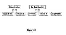
- An illustrative block diagram of the application scenario is given in
Fig. 2 . The n-bit depth map is first quantized to 8-bit to be compatible to a standard encoder. After encoding/decoding process, the depth data is dequantized back to n-bit representation. - Additionally, inR. Krishnamurthy, B. Chai, H. Tao and S. Sethuraman, "Compression and transmission of depth maps for image-based rendering", Proc. of International Conference on Image processing (ICIP'2001), Thessaloniki, Greece, Oct. 2001, a method for reshaping dynamic range of depth in order to reflect the different importance of different depths is proposed. This approach is based on the observation that the errors were much more significant in the areas of smaller depth (largerk), therefore, reshaping the dynamic range of depth is done using a similar idea to companding, which is used in encoding speech signals. First the depth map is scaled to a value [0,1]. Then the depth-map is passed through a function that expands the dynamic range for higherk's and compresses the dynamic range for lowerk's (Note that this is opposite to the action of a traditional compander used in speech).
- The function used for reshaping in this example is the quadratic function from (1).

- Then k' values are encoded using the JPEG-2000 algorithm after scaling this floating point number to a 16-bit number.
- The invention addresses the problem of quantization of the depth data accompanying a video or graphics image prior to coding in order to exploit the distribution of objects in the scene, especially non-linear distribution. For example, some depth values may not appear at all in the scene while others need to be more finely quantized than would be the case with linear quantization of the whole scene.
- In contrast to the idea in
US 6,055,330 , no objects map associated to the different values of depth in the image is created. - Unlike
US 6,104,837 , we do not identify patches of importance in the depth image and eliminate areas considered to be unimportant. - Our approach takes into account the depth image as a whole without performing explicit segmentation of the objects against the background.
- The invention also addresses the problem of de-quantization of depth data consisting of re-mapping the pixels back from m-bit to n-bit (with n>m) representation.
- Aspects of the invention are set out in the accompanying claims.
- A non-linear piecewise function is derived from the distribution of the depth data accompanying a video or graphics image, in order to create a suitable mapping to lower precision acceptable by a standard video encoder. Unlike the linear approach, the non-linear mapping takes into account the actual depth values occurring in the scene and creates a suitable mapping relation to displacement and extraction. The inventive idea also addresses non-linear de-quantization following the encoding/decoding process, where the m-bit depth data is re-mapped to n-bit data (with n>m) using an appropriate reconstruction value calculated for each bin.
- We consider a number of approaches to the problem that offer different trade-offs between efficiency and complexity and may be applicable in different application scenarios (different type of images computer-generated or natural images). These are described in the following section.
- Embodiments of the invention will be described with reference to the accompanying drawings, of which:
Fig. 1 is a diagram illustrating a prior art method;Fig. 2 is a block diagram of a prior art system;Fig. 3 is a diagram illustrating a method according to a first embodiment of the invention;Fig. 4 is a flow diagram illustrating a method according to a first embodiment of the invention; andFig. 5 is a flow diagram of a method according to a second embodiment of the invention.- According to the embodiments of the invention, the approach to estimation is to assign more quantization cells to the regions with high histogram count of depth values and approximate the resulting mapping function with higher accuracy.
- An example of the general block diagram of the non-linear quantization from 16-bit data to 8-bit data is given in
Fig. 3 . The resulting 256 bins will be non-equally spaced containing the same number of pixels and having different width. - The procedure of building the bins applicable to each of the field/frame in the depth video sequence is as shown in
Fig. 3 and described below. - From a 16-bit frame/field of the depth map in the video sequence, a 16-bit depth histogram, namely H16 is produced. This histogram contains 216 numbers of bins, each bin having the width equal to 1. This is equal to the number of grey levels possible to be encountered in a 16-bit data representation. Hence H16 is a representation of the total number of pixels for each intensity level in the 16-bit image.
- We introduce the following notations:
- Hi represents the number of pixels at each level i in the 16 bit data as follows:


- f:i->Hi represents the PDF (Probability Density Function) of H16
- H8 represents the 8-bit histogram to be derived from the 16-bit depth map.
- hm represents the number of pixels at each level m in the 8 bit data as follows:


- In order to build H8, the array H; is checked for non-zero values to take into account only the existing depth value in the image. Approximately the same number of pixels is assigned to each bin in the 8-bit histogram. To this end, a threshold value equivalent toTH =WidthxHeight/256 is chosen, whereWidth andHeight represent the dimensions of the depth image.
- The process of distributing (mapping) pixels from the H16 to H8 is carried out by adding up the consecutive values ofHi until the threshold value is reached. If the checked non-zero valueHi is greater then the threshold, all the pixelsHi fill the corresponding binBm in the 8-bit histogram. Moreover, at this stage, an overflow is calculated to keep an indication of the number of pixels overfloating the threshold value. This overflow value is taken into account when filling the next bin where it represents the starting value in calculating the number of pixels in this current bin. This means that, a counter variable used to count the number of pixels in the current bin will start at a non-zero value, specifically the value of overflow. This is a reference value only in order to keep the statistic of the pixels in the image, since no transfer of pixels takes place when the threshold value is overflown.
- If the checked non-zero valueHi is less then the threshold, then this value is added to the next valueHi+1 and so on filling an accumulator until the sum becomes greater than the threshold. In this situation, the entire sum of pixels added up so far will fill the binBm. The procedure continues until all the bins in the H8 will be filled.
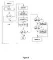
- Based on this approach, the method of assigning pixels from the n-bit data to the 8-bit histogram can simply be described as shown in
Fig. 4 . - In
Figure 4 : - ov = overflow;
- ACC = accumulator;
- N = number of bit/pixel in the original depth data
- i, index = counters
- Xi = number of pixels in bini in original depth data.
- Experiments have been carried out comparing linear quantization, as in the prior art, with non-linear quantization as in the above embodiments of the present invention. More specifically, sequences of images were quantized from 16-bit to 8-bit using each of linear quantization and non-linear quantization and dequantized accordingly. The PSNR (peak signal to noise ratio) of the reconstructed image sequences in each case were calculated and compared. These experiments showed that on average the PSNR using non-linear quantization was greater than for linear quantization.NLPSNR >LPSNR
- Although overall, the PNSR is better using non-linear quantization, it has been found that for some frames, the PSNR may be better for linear quantization. Further examination suggested that this may be related to situations where the width of a bin is extremely large and where there may be a small number of isolated pixels situated at the edge of the bins. These particular bins are far from the weighted value of the bin. Since the weighted value represents the estimated value when re-mapping back to 16-bit, those isolated pixels may introduce an error in the reconstructed 16-bit image. The further away from the weighted value, the larger the error is.
- These errors can be reduced if we introduce a limit to the width of the bin. The following statistics were drawn from experiments.
Table 1 Experimental observation BNL>BL PSNRNL>PSNRL 10 times approx. +7dB 25 times approx. +3dB 40 times approx. -3dB • BNL = the width of the bin in the Non-linear quantizer • BL = the width of the bin in the Linear quantizer - Based on this observation, a threshold value has been used to limit the size of a bin in the NL quantizer.
- In some cases, for a particular distribution of the original n-bit depth map data, say for example when same of the resultant bins are extremely large, further steps are required. This refers to a checking stage introduced to verify the size of each of the 256 resultant bins (Bm) in the H8 histogram. This will imply that a large bin, whose width is bigger than a chosen threshold will be split into smaller bins. Since the final number of bins should not be higher then 256, a new threshold value defining the number of pixels in each rearranged bin is calculated and a new re-mapping is applied.
- The description of the algorithm is as follows:
- •Step1. Calculate a pixel threshold value TH1pixel=WidthXHeight/256. Assign to each of the Bin in the 8-bit histogram a number of pixels related to TH1pixel pixels (see the method of assigning pixels above).
- •Step2. Cheque the width of each bin B8i;if this is greater than a threshold THwidth,mark those bins for splitting (NoBinsForSplit)and calculate the numbers of pixels contained in these bins (ACC). Split these bins in equal-width bins.
- •Step3. Calculate a new pixel threshold value TH2pixel =(TotalNoOfPixels-ACC)/(256-NoBinsForSplit). Assign to each new bin TH2pixel pixels.
- This can be a non-linear recursive implementation where the size of the bins is re-updated based on the volume (number of pixels in each bin) and width of the bin simultaneously until a final number of 256 bins is reached.
- For each bin a representative value is calculated, that can be either the average value of the bin or the weighted average value of the bin, which will be used in the de-quantization process. The weighted average value is:

where : - •Hi represents the grey level value with i∈{0 .. 65535}
- •Ni represents the number of pixels with grey level value Hi
- A second embodiment involves non-linear quantization with pixels clustering.
- In this approach, the size of the non-linear bins is decided by minimizing an error measure in each bin. In the original n-bit histogram, pixels will be grouped (clustered) into bins based on error measurement. The error is calculated as a sum of squared differences between the pixels in the bin and the representative weighted value of the bin. This is a recursive implementation in which a threshold value (error threshold) is re-updated until a final number of bins equal to 256 is reached.
- The array of weighted values calculated in the quantization stage will be used in the de-quantization process for re-mapping from 8-bit to n-bit (with n>8) depth data.
- A flow diagram illustrating this method is shown in
Figure 5 . - The PSNR values after re-mapping show that for all frames in both video sequences tested the PSNR values corresponding to the NL quantizer are higher than their Linear equivalent. An average gain of 2.5 dB is obtained by using the NL quantizer when limiting the width of the bin.
- In a third embodiment, an algorithm based on Max-Lloyd quantizer for optimal scalar quantization can be used (seeDavid S. Taubman and Michael W. Marcellin, "JPEG2000: Image Compression Fundamentals, Standards and Practice". Boston, Kluwer Academic Publishers, 2002(pp. 98-101).
- The quantizer takes an n-bit depth-map (x) as input and maps it to 256-level (Li corresponding to each bin Bi) so that distortionD is minimised; where


- The quantizer is optimum when it satisfies two conditions:
- (i) Q must be a nearest neighbor quantizer. This means that the quantized value Q(x) for any real x must be a quantization level in{L1; L2; : : :;L256} which is at least as close tox as any other quantization level:

- (ii) Each quantization level must be the average of all samples quantized to that level:

- With the above notations, the description of the Lloyd-Max algorithm is as follow:
- 1. Choose an initial codeC={L1,L2,...,L256} assumed to be the values of the centroids
- 2. Calculate the border of each bin as midpoint between consecutiveLi

- 3. Recalculate the values of centroids

- 4. Calculate distortion Dn as

- 5. If

- In a further implementation, local adjustment (in the spatial domain) of the mapping could be introduced to take into account:
- • The quality of depth estimation
- • The amount of texture in the region
- • The edges in the depth map (this would be a replacement of the approach based on ROI coding)
- One possible mechanism for this in an MPEG-like codec would be to pre-define a set of mappings in the picture header and switch between them on the macroblock level.
- The non-linear quantization/de-quantization method proposed here relies on multiple histogram calculation, one for each frame/field in the video sequence. To reduce the amount of information to be transferred to the de-quantizer (the array of weighted values), an averaged histogram can be calculated with a corresponding array of averaged weighted values. In this case, all the frames/fields in the video sequence would refer to the averaged weighted vector in the de-quantization process. Another approach would consider an adjusted histogram, which means that we only have to calculate the histogram corresponding to the first frame/field in the video sequence, and adjust the histogram of the next frame based on differences between the frames. For the latter case one possible implementation would be to initialise the Lloyd-Max quantizer described above to the previous quantization map. Based on an appropriate distortion criterion value (e.g. MSE of corresponding reconstruction values or quantization boundaries), the system would decide whether an update of the mapping is necessary and send it differentially if necessary.
- The non-linear quantization of the depth map proposed here is meant to exploit the nonlinear relation between depth and displacement and, consequently the reconstructed picture. It can be combined with the method proposed by Krishnamurty et al. in R. Krishnamurthy, B. Chai, H. Tao andS. Sethuraman, "Compression and transmission of depth maps for image-based rendering", Proc. of International Conference on Image processing (ICIP'2001), Thessaloniki, Greece, Oct. 2001, based on reshaping of the dynamic range of depth maps by use of a scaling function.
- Experiments using the second and third embodiments, for sequences of images and measurement of PSNR as described for the first embodiment, have shown that the PSNR using the NL quantizer is greater compared with a linear quantizer. In one example, for given sequence of images, an average improvement of approximately 12dB was found for the NL quantizer with pixels clustering compared with the linear quantizer, and an extra 0.7dB was attained by the scalar optimised quantizer.
- Further experiments involved coding the 8-bit depth map using a standard codec (such as H263/DCT based or wavelet based encoder) and similarly decoding and dequantizing back to 16-bit. In one example, an average gain of approximately 0.6dB was found using non-linear quantization in the encoding loop compared with linear quantization.
- In the specification, the term image means a whole image or a region of an image, except where apparent from the context. Similarly, a region of an image can mean the whole image. An image includes a frame or a field, and relates to a still image or an image in a sequence of images such as a film or video, or in a related group of images.
- The image may be a grayscale or colour image, or another type of multi-spectral image, for example, IR, UV or other electromagnetic image, or an acoustic image etc.
- The invention can be implemented for example in a computer system, with suitable software and/or hardware modifications, or similarly an encoder and/or decoder system. Aspects of the invention can be provided in software and/or hardware form, or in an application-specific apparatus or application-specific modules can be provided, such as chips. Components of a system in an apparatus according to an embodiment of the invention may be provided remotely from other components.


Claims (20)
- A method of representing an image or a sequence of images using a depth map comprising requantizing an n-bit depth map representation into an m-bit depth map representation, where m<n, using a non-linear transformation,characterised by transforming a depth map in the form of an n-bin histogram into a second m-bin histogram, the widths of at least two bins in the m-bin histogram being unequal, by predetermining the m bins of the second histogram and by combining bins of the first n-bin histogram by mapping pixels from one or more bins of the first histogram into a bin of the second histogram.
- The method of claim 1 wherein more bins in the second histogram correspond to bins of the first histogram having higher histogram count.
- The method of claim 1 or claim 2 wherein approximately the same number of pixels is assigned to each bin the m-bit histogram.
- The method of any preceding claim wherein the non-linear transformation is a piecewise linear transformation, each piecewise linear transformation mapping one or more bins of the first histogram into a bin of the second histogram.
- The method of any preceding claim comprising mapping until the number of pixels in the bin of the second histogram exceeds a predetermined threshold.
- The method of claim 5 wherein the threshold TH=WidthxHeight/2m where width and height represent the dimensions of the image.
- The method of any preceding claim comprising grouping pixels into bins using an error measurement.
- The method of claim 7 wherein the error value is the sum of squared differences between the pixels in the bin and a representative value of the bin, for example, a representative weighted value of the bin.
- The method of any preceding claim, wherein the transformation is recursive and involves intermediate transformations to one or more p-bin histograms, where p is variable.
- The method of any preceding claim using an algorithm based on a Max-Lloyd quantizer.
- The method of any preceding claim wherein m=8.
- The method of any preceding claim wherein for different areas of an image, different transformations or different quantization steps are used, based on a predetermined criterion.
- The method of any preceding claim for representing a sequence of images wherein said representation is derived for each of a plurality of images in the sequence.
- The method of any preceding claim for representing a sequence of images wherein said representation is derived for a plurality of images.
- The method of claim 14 comprising combining depth map histograms for the plurality of images and deriving the m-bit map representation from the combined histogram.
- The method of any preceding claim for representing a sequence of images comprising comparing the depth map for a first image with the depth map for a second image and determining the representation for the first image based on the comparison.
- A method of representing an image or a sequence of images using a depth map comprising dequantizing an m-bit depth map representation to an n-bit depth map representation, where m<n, using a non-linear transformation,characterised by comprising transforming a depth map in the form of an m-bin histogram into a second n-bin histogram, the widths of at least two bins in the m-bin histogram being unequal, using a non-linear transformation that is piecewise linear.
- Apparatus adapted to perform the method of any preceding claim.
- Apparatus as claimed in claim 18 comprising means for executing the method of any of claims 1 to 17 and one or more of storage means for storing images and/or descriptors of images, display means for displaying images, input means for inputting images, coding and/or decoding means, transmitting and/or receiving means for transmitting and/or receiving images, processing means, storage means storing instructions for executing the method of any of claims 1 to 17.
- A computer-readable storage medium storing a computer program for executing the method of any of claims 1 to 17.
Priority Applications (4)
| Application Number | Priority Date | Filing Date | Title |
|---|---|---|---|
| DE602004014901TDE602004014901D1 (en) | 2004-04-29 | 2004-04-29 | Adaptive quantization of a depth map |
| EP04252510AEP1591963B1 (en) | 2004-04-29 | 2004-04-29 | Adaptive quantisation of a depth map |
| US11/110,764US7558432B2 (en) | 2004-04-29 | 2005-04-21 | Adaptive quantization of depth signal in 3D visual coding |
| JP2005132792AJP2005341555A (en) | 2004-04-29 | 2005-04-28 | Method for representing image or image sequence, descriptor for representing image and method for using the same, and apparatus, computer program, and storage medium for performing these methods |
Applications Claiming Priority (1)
| Application Number | Priority Date | Filing Date | Title |
|---|---|---|---|
| EP04252510AEP1591963B1 (en) | 2004-04-29 | 2004-04-29 | Adaptive quantisation of a depth map |
Publications (2)
| Publication Number | Publication Date |
|---|---|
| EP1591963A1 EP1591963A1 (en) | 2005-11-02 |
| EP1591963B1true EP1591963B1 (en) | 2008-07-09 |
Family
ID=34930275
Family Applications (1)
| Application Number | Title | Priority Date | Filing Date |
|---|---|---|---|
| EP04252510AExpired - LifetimeEP1591963B1 (en) | 2004-04-29 | 2004-04-29 | Adaptive quantisation of a depth map |
Country Status (4)
| Country | Link |
|---|---|
| US (1) | US7558432B2 (en) |
| EP (1) | EP1591963B1 (en) |
| JP (1) | JP2005341555A (en) |
| DE (1) | DE602004014901D1 (en) |
Families Citing this family (56)
| Publication number | Priority date | Publication date | Assignee | Title |
|---|---|---|---|---|
| US8313380B2 (en) | 2002-07-27 | 2012-11-20 | Sony Computer Entertainment America Llc | Scheme for translating movements of a hand-held controller into inputs for a system |
| US8570378B2 (en)* | 2002-07-27 | 2013-10-29 | Sony Computer Entertainment Inc. | Method and apparatus for tracking three-dimensional movements of an object using a depth sensing camera |
| US9393487B2 (en) | 2002-07-27 | 2016-07-19 | Sony Interactive Entertainment Inc. | Method for mapping movements of a hand-held controller to game commands |
| KR100703799B1 (en)* | 2005-07-19 | 2007-04-06 | 삼성전자주식회사 | Inverse quantization method and apparatus, video decoding method and apparatus using the method |
| US20070269123A1 (en)* | 2006-05-16 | 2007-11-22 | Randall Don Briggs | Method and apparatus for performing image enhancement in an image processing pipeline |
| JP5384330B2 (en)* | 2006-05-25 | 2014-01-08 | トムソン ライセンシング | Weighted encoding method and system |
| JP4991851B2 (en)* | 2006-07-17 | 2012-08-01 | トムソン ライセンシング | Method and apparatus for encoding video color enhancement data and method and apparatus for decoding video color enhancement data |
| WO2008026145A2 (en) | 2006-08-30 | 2008-03-06 | Koninklijke Philips Electronics N.V. | Device and method for coding a data signal and device and method for decoding a data signal |
| US8395658B2 (en)* | 2006-09-07 | 2013-03-12 | Sony Computer Entertainment Inc. | Touch screen-like user interface that does not require actual touching |
| US8310656B2 (en) | 2006-09-28 | 2012-11-13 | Sony Computer Entertainment America Llc | Mapping movements of a hand-held controller to the two-dimensional image plane of a display screen |
| USRE48417E1 (en) | 2006-09-28 | 2021-02-02 | Sony Interactive Entertainment Inc. | Object direction using video input combined with tilt angle information |
| US8781151B2 (en) | 2006-09-28 | 2014-07-15 | Sony Computer Entertainment Inc. | Object detection using video input combined with tilt angle information |
| KR101311896B1 (en)* | 2006-11-14 | 2013-10-14 | 삼성전자주식회사 | Displacement adjustment method of stereoscopic image and stereoscopic image device applying the same |
| EP2153669B1 (en)* | 2007-05-11 | 2012-02-01 | Koninklijke Philips Electronics N.V. | Method, apparatus and system for processing depth-related information |
| KR101367282B1 (en) | 2007-12-21 | 2014-03-12 | 삼성전자주식회사 | Method and Apparatus for Adaptive Information representation of 3D Depth Image |
| US20100295922A1 (en)* | 2008-01-25 | 2010-11-25 | Gene Cheung | Coding Mode Selection For Block-Based Encoding |
| WO2010093351A1 (en)* | 2009-02-13 | 2010-08-19 | Thomson Licensing | Depth map coding to reduce rendered distortion |
| JP5027171B2 (en)* | 2009-02-25 | 2012-09-19 | 日本電信電話株式会社 | Image coding method, image coding apparatus, and image coding program |
| WO2010108024A1 (en)* | 2009-03-20 | 2010-09-23 | Digimarc Coporation | Improvements to 3d data representation, conveyance, and use |
| WO2010151279A1 (en) | 2009-06-25 | 2010-12-29 | Thomson Licensing | Depth map coding |
| KR101642965B1 (en)* | 2009-12-21 | 2016-07-26 | 삼성전자주식회사 | Apparatus and method for processing depth image using bit depth reduction |
| KR101885258B1 (en) | 2010-05-14 | 2018-08-06 | 삼성전자주식회사 | Method and apparatus for video encoding, and method and apparatus for video decoding |
| US8488870B2 (en)* | 2010-06-25 | 2013-07-16 | Qualcomm Incorporated | Multi-resolution, multi-window disparity estimation in 3D video processing |
| KR101702948B1 (en) | 2010-07-20 | 2017-02-06 | 삼성전자주식회사 | Rate-Distortion Optimization Apparatus and Method for depth-image encoding |
| US20120133639A1 (en)* | 2010-11-30 | 2012-05-31 | Microsoft Corporation | Strip panorama |
| JP5242667B2 (en)* | 2010-12-22 | 2013-07-24 | 株式会社東芝 | Map conversion method, map conversion apparatus, and map conversion program |
| JP5757446B2 (en)* | 2011-06-09 | 2015-07-29 | ソニー株式会社 | Image processing apparatus and method |
| EP2552099B1 (en)* | 2011-07-27 | 2013-08-28 | Axis AB | Method and camera for providing an estimation of a mean signal to noise ratio value for an image |
| EP2742688A1 (en)* | 2011-08-12 | 2014-06-18 | Telefonaktiebolaget LM Ericsson (PUBL) | Signaling of camera and/or depth parameters |
| US20130106990A1 (en) | 2011-11-01 | 2013-05-02 | Microsoft Corporation | Planar panorama imagery generation |
| PL397016A1 (en)* | 2011-11-17 | 2013-05-27 | Politechnika Poznanska | Encoding method for the stereoscopic depth |
| US9324184B2 (en) | 2011-12-14 | 2016-04-26 | Microsoft Technology Licensing, Llc | Image three-dimensional (3D) modeling |
| US10008021B2 (en) | 2011-12-14 | 2018-06-26 | Microsoft Technology Licensing, Llc | Parallax compensation |
| US9406153B2 (en) | 2011-12-14 | 2016-08-02 | Microsoft Technology Licensing, Llc | Point of interest (POI) data positioning in image |
| US9626793B2 (en) | 2011-12-29 | 2017-04-18 | Intel Corporation | Variable depth compression |
| US20130245983A1 (en)* | 2012-03-15 | 2013-09-19 | Research In Motion Limited | Method and devices for determining gyroscope bias |
| JP5959911B2 (en)* | 2012-04-17 | 2016-08-02 | キヤノン株式会社 | Quantization apparatus and control method thereof |
| US9288377B2 (en)* | 2012-05-02 | 2016-03-15 | Semiconductor Components Industries, Llc | System and method for combining focus bracket images |
| US9307252B2 (en) | 2012-06-04 | 2016-04-05 | City University Of Hong Kong | View synthesis distortion model for multiview depth video coding |
| EP2706503A3 (en)* | 2012-09-11 | 2017-08-30 | Thomson Licensing | Method and apparatus for bilayer image segmentation |
| WO2014051319A1 (en)* | 2012-09-28 | 2014-04-03 | 삼성전자주식회사 | Method and apparatus for encoding depth image, and method and apparatus for decoding depth image |
| KR102232250B1 (en)* | 2012-11-27 | 2021-03-25 | 인텔렉추얼디스커버리 주식회사 | Method for encoding and decoding image using depth information, and device and image system using same |
| US9704226B2 (en)* | 2013-03-14 | 2017-07-11 | Drs Network & Imaging Systems, Llc | System and method for fast digital signal dynamic range reduction using adaptive histogram compaction and stabilization |
| US9344218B1 (en) | 2013-08-19 | 2016-05-17 | Zoom Video Communications, Inc. | Error resilience for interactive real-time multimedia applications |
| JP2017050592A (en)* | 2015-08-31 | 2017-03-09 | ルネサスエレクトロニクス株式会社 | Image encoding device, image decoding device, and image transmission device |
| US10311558B2 (en)* | 2015-11-16 | 2019-06-04 | Dolby Laboratories Licensing Corporation | Efficient image processing on content-adaptive PQ signal domain |
| WO2017107192A1 (en)* | 2015-12-25 | 2017-06-29 | Boe Technology Group Co., Ltd. | Depth map generation apparatus, method and non-transitory computer-readable medium therefor |
| JP6538572B2 (en)* | 2016-01-08 | 2019-07-03 | 日本電信電話株式会社 | Quantization method, quantization device and quantization program |
| US10776992B2 (en)* | 2017-07-05 | 2020-09-15 | Qualcomm Incorporated | Asynchronous time warp with depth data |
| EP3554074A1 (en)* | 2018-04-13 | 2019-10-16 | Thomson Licensing | Methods and apparatus for depth encoding and decoding |
| EP3834135A4 (en) | 2018-08-07 | 2022-05-04 | BlinkAI Technologies, Inc. | ARTIFICIAL INTELLIGENCE METHOD FOR IMAGE ENHANCEMENT |
| EP3614674A1 (en)* | 2018-08-23 | 2020-02-26 | Nokia Technologies Oy | An apparatus, a method and a computer program for volumetric video |
| BR112021016388A2 (en) | 2019-03-19 | 2021-11-23 | Intel Corp | Method, system and at least one machine-readable medium |
| EP3713237A1 (en) | 2019-03-20 | 2020-09-23 | InterDigital VC Holdings, Inc. | A method and apparatus for depth encoding and decoding |
| EP4154171A1 (en)* | 2020-07-02 | 2023-03-29 | Meta Platforms, Inc. | Systems and methods of nonlinear image intensity transformation for denoising and low-precision image processing |
| CN113160097B (en)* | 2021-03-26 | 2023-12-22 | 中国航空无线电电子研究所 | Infrared image quantization method based on histogram transformation |
Family Cites Families (7)
| Publication number | Priority date | Publication date | Assignee | Title |
|---|---|---|---|---|
| JPH05225322A (en)* | 1991-11-27 | 1993-09-03 | Ezel Inc | Picture data compression method |
| US5644651A (en)* | 1995-03-31 | 1997-07-01 | Nec Research Institute, Inc. | Method for the estimation of rotation between two frames via epipolar search for use in a three-dimensional representation |
| GB9613039D0 (en)* | 1996-06-21 | 1996-08-28 | Philips Electronics Nv | Image data compression for interactive applications |
| US6055330A (en)* | 1996-10-09 | 2000-04-25 | The Trustees Of Columbia University In The City Of New York | Methods and apparatus for performing digital image and video segmentation and compression using 3-D depth information |
| JP3484982B2 (en)* | 1998-07-17 | 2004-01-06 | 富士通株式会社 | Dynamic range extended display method for each object |
| US6671419B1 (en)* | 1999-07-02 | 2003-12-30 | Intel Corporation | Method for reducing shadows and/or noise in a digital image |
| KR20020031015A (en)* | 2000-10-21 | 2002-04-26 | 오길록 | Non-linear quantization and similarity matching methods for edge histogram bins |
- 2004
- 2004-04-29EPEP04252510Apatent/EP1591963B1/ennot_activeExpired - Lifetime
- 2004-04-29DEDE602004014901Tpatent/DE602004014901D1/ennot_activeExpired - Lifetime
- 2005
- 2005-04-21USUS11/110,764patent/US7558432B2/ennot_activeExpired - Fee Related
- 2005-04-28JPJP2005132792Apatent/JP2005341555A/enactivePending
Also Published As
| Publication number | Publication date |
|---|---|
| EP1591963A1 (en) | 2005-11-02 |
| US20050244071A1 (en) | 2005-11-03 |
| US7558432B2 (en) | 2009-07-07 |
| JP2005341555A (en) | 2005-12-08 |
| DE602004014901D1 (en) | 2008-08-21 |
Similar Documents
| Publication | Publication Date | Title |
|---|---|---|
| EP1591963B1 (en) | Adaptive quantisation of a depth map | |
| Nguyen et al. | Learning-based lossless compression of 3d point cloud geometry | |
| Merkle et al. | The effects of multiview depth video compression on multiview rendering | |
| US7428338B2 (en) | Header-based processing of images compressed using multi-scale transforms | |
| US20060039617A1 (en) | Method and assembly for video encoding, the video encoding including texture analysis and texture synthesis, and corresponding computer program and corresponding computer-readable storage medium | |
| CN100399357C (en) | Motion residual frame coding method and device based on overcomplete basis transformation for video compression | |
| JP2000511366A (en) | Apparatus and method for variable block size motion estimation based on quadrant tree | |
| JPH0670178A (en) | Encoding device for picture signal | |
| US12206875B2 (en) | Systems and methods for improving object tracking in compressed feature data in coding of multi-dimensional data | |
| Zanuttigh et al. | Compression of depth information for 3D rendering | |
| Santos et al. | Lossless coding of light field images based on minimum-rate predictors | |
| Cai et al. | An adaptive pyramid single-view depth lookup table coding method | |
| WO2023149367A1 (en) | Systems and methods for improving object detection in compressed feature data in coding of multi-dimensional data | |
| Watanabe et al. | Lossless two-layer coding using histogram packing technique for HDR images | |
| Kavitha et al. | Lossy compression through segmentation on low depth-of-field images | |
| JP4195978B2 (en) | Video signal encoding apparatus and method, and recording medium | |
| Kang et al. | Geometry-based block partitioning for efficient intra prediction in depth video coding | |
| Pasteau et al. | Improved colour decorrelation for lossless colour image compression using the LAR codec | |
| Kobayashi et al. | Two-Layer Near-Lossless HDR Coding Using Zero-Skip Quantization with Backward Compatibility to JPEG | |
| Miao et al. | Layered compression for high-precision depth data | |
| Palfner et al. | Progressive coding of stereo images using a hybrid scheme | |
| Matsuo et al. | A JPEG2000 re-encoding scheme with high quality performance for JPEG coded pictures | |
| Wang et al. | A fractal-based hybrid image coding system | |
| Mathur et al. | A low bit rate video coder using content-based automatic segmentation and shape-adaptive DCT | |
| JP2816169B2 (en) | Image data compression device |
Legal Events
| Date | Code | Title | Description |
|---|---|---|---|
| PUAI | Public reference made under article 153(3) epc to a published international application that has entered the european phase | Free format text:ORIGINAL CODE: 0009012 | |
| AK | Designated contracting states | Kind code of ref document:A1 Designated state(s):AT BE BG CH CY CZ DE DK EE ES FI FR GB GR HU IE IT LI LU MC NL PL PT RO SE SI SK TR | |
| AX | Request for extension of the european patent | Extension state:AL HR LT LV MK | |
| RAP1 | Party data changed (applicant data changed or rights of an application transferred) | Owner name:MITSUBISHI ELECTRIC INFORMATION TECHNOLOGY CENTRE Owner name:MITSUBISHI DENKI KABUSHIKI KAISHA | |
| 17P | Request for examination filed | Effective date:20060427 | |
| AKX | Designation fees paid | Designated state(s):DE FR GB | |
| 17Q | First examination report despatched | Effective date:20060627 | |
| GRAP | Despatch of communication of intention to grant a patent | Free format text:ORIGINAL CODE: EPIDOSNIGR1 | |
| GRAS | Grant fee paid | Free format text:ORIGINAL CODE: EPIDOSNIGR3 | |
| GRAA | (expected) grant | Free format text:ORIGINAL CODE: 0009210 | |
| RAP1 | Party data changed (applicant data changed or rights of an application transferred) | Owner name:MITSUBISHI DENKI KABUSHIKI KAISHA Owner name:MITSUBISHI ELECTRIC INFORMATION TECHNOLOGY CENTRE | |
| AK | Designated contracting states | Kind code of ref document:B1 Designated state(s):DE FR GB | |
| REG | Reference to a national code | Ref country code:GB Ref legal event code:FG4D | |
| REF | Corresponds to: | Ref document number:602004014901 Country of ref document:DE Date of ref document:20080821 Kind code of ref document:P | |
| PLBE | No opposition filed within time limit | Free format text:ORIGINAL CODE: 0009261 | |
| STAA | Information on the status of an ep patent application or granted ep patent | Free format text:STATUS: NO OPPOSITION FILED WITHIN TIME LIMIT | |
| 26N | No opposition filed | Effective date:20090414 | |
| REG | Reference to a national code | Ref country code:FR Ref legal event code:PLFP Year of fee payment:13 | |
| REG | Reference to a national code | Ref country code:FR Ref legal event code:PLFP Year of fee payment:14 | |
| REG | Reference to a national code | Ref country code:DE Ref legal event code:R084 Ref document number:602004014901 Country of ref document:DE | |
| REG | Reference to a national code | Ref country code:GB Ref legal event code:746 Effective date:20180202 | |
| REG | Reference to a national code | Ref country code:FR Ref legal event code:PLFP Year of fee payment:15 | |
| PGFP | Annual fee paid to national office [announced via postgrant information from national office to epo] | Ref country code:FR Payment date:20190313 Year of fee payment:16 | |
| PGFP | Annual fee paid to national office [announced via postgrant information from national office to epo] | Ref country code:DE Payment date:20190416 Year of fee payment:16 | |
| PGFP | Annual fee paid to national office [announced via postgrant information from national office to epo] | Ref country code:GB Payment date:20190424 Year of fee payment:16 | |
| REG | Reference to a national code | Ref country code:DE Ref legal event code:R119 Ref document number:602004014901 Country of ref document:DE | |
| PG25 | Lapsed in a contracting state [announced via postgrant information from national office to epo] | Ref country code:DE Free format text:LAPSE BECAUSE OF NON-PAYMENT OF DUE FEES Effective date:20201103 | |
| GBPC | Gb: european patent ceased through non-payment of renewal fee | Effective date:20200429 | |
| PG25 | Lapsed in a contracting state [announced via postgrant information from national office to epo] | Ref country code:GB Free format text:LAPSE BECAUSE OF NON-PAYMENT OF DUE FEES Effective date:20200429 | |
| PG25 | Lapsed in a contracting state [announced via postgrant information from national office to epo] | Ref country code:FR Free format text:LAPSE BECAUSE OF NON-PAYMENT OF DUE FEES Effective date:20200430 |