EP1587725B1 - Robotic cart pulling vehicle - Google Patents
Robotic cart pulling vehicleDownload PDFInfo
- Publication number
- EP1587725B1 EP1587725B1EP03752029.3AEP03752029AEP1587725B1EP 1587725 B1EP1587725 B1EP 1587725B1EP 03752029 AEP03752029 AEP 03752029AEP 1587725 B1EP1587725 B1EP 1587725B1
- Authority
- EP
- European Patent Office
- Prior art keywords
- cart
- wheel
- robotic
- contact surface
- pulling vehicle
- Prior art date
- Legal status (The legal status is an assumption and is not a legal conclusion. Google has not performed a legal analysis and makes no representation as to the accuracy of the status listed.)
- Expired - Lifetime
Links
- 230000007246mechanismEffects0.000claimsdescription18
- 238000012546transferMethods0.000claimsdescription12
- 239000011248coating agentSubstances0.000claimsdescription11
- 238000000576coating methodMethods0.000claimsdescription11
- 230000006835compressionEffects0.000claimsdescription9
- 238000007906compressionMethods0.000claimsdescription9
- 239000007787solidSubstances0.000claimsdescription6
- 230000006872improvementEffects0.000claimsdescription4
- 230000008878couplingEffects0.000claimsdescription3
- 238000010168coupling processMethods0.000claimsdescription3
- 238000005859coupling reactionMethods0.000claimsdescription3
- 230000002547anomalous effectEffects0.000claimsdescription2
- 238000000034methodMethods0.000description11
- 238000013461designMethods0.000description10
- 238000012937correctionMethods0.000description8
- 238000001514detection methodMethods0.000description6
- JOYRKODLDBILNP-UHFFFAOYSA-NEthyl urethaneChemical compoundCCOC(N)=OJOYRKODLDBILNP-UHFFFAOYSA-N0.000description5
- 239000000463materialSubstances0.000description5
- 238000005259measurementMethods0.000description5
- RYGMFSIKBFXOCR-UHFFFAOYSA-NCopperChemical group[Cu]RYGMFSIKBFXOCR-UHFFFAOYSA-N0.000description4
- 230000008859changeEffects0.000description4
- 238000009825accumulationMethods0.000description3
- 230000008901benefitEffects0.000description3
- 238000004140cleaningMethods0.000description3
- 239000002184metalSubstances0.000description3
- 229910052751metalInorganic materials0.000description3
- 238000012986modificationMethods0.000description3
- 230000004048modificationEffects0.000description3
- 229910000831SteelInorganic materials0.000description2
- 230000001133accelerationEffects0.000description2
- 230000003466anti-cipated effectEffects0.000description2
- 230000000694effectsEffects0.000description2
- 238000005096rolling processMethods0.000description2
- 238000007619statistical methodMethods0.000description2
- 239000010959steelSubstances0.000description2
- 230000000153supplemental effectEffects0.000description2
- 229910001369BrassInorganic materials0.000description1
- 241000931888PyxisSpecies0.000description1
- 230000002411adverseEffects0.000description1
- 238000013459approachMethods0.000description1
- 239000010951brassSubstances0.000description1
- 150000001875compoundsChemical class0.000description1
- 238000010276constructionMethods0.000description1
- 230000008030eliminationEffects0.000description1
- 238000003379elimination reactionMethods0.000description1
- 238000003780insertionMethods0.000description1
- 230000037431insertionEffects0.000description1
- 230000010354integrationEffects0.000description1
- 238000013507mappingMethods0.000description1
- 239000003550markerSubstances0.000description1
- 230000003287optical effectEffects0.000description1
- 229920002635polyurethanePolymers0.000description1
- 239000004814polyurethaneSubstances0.000description1
- 230000009467reductionEffects0.000description1
- 238000002310reflectometryMethods0.000description1
- 238000011160researchMethods0.000description1
- 238000009420retrofittingMethods0.000description1
- 238000000926separation methodMethods0.000description1
- 239000013589supplementSubstances0.000description1
- 230000009897systematic effectEffects0.000description1
- 230000000007visual effectEffects0.000description1
Images


Classifications
- G—PHYSICS
- G05—CONTROLLING; REGULATING
- G05D—SYSTEMS FOR CONTROLLING OR REGULATING NON-ELECTRIC VARIABLES
- G05D1/00—Control of position, course, altitude or attitude of land, water, air or space vehicles, e.g. using automatic pilots
- G05D1/02—Control of position or course in two dimensions
- G05D1/021—Control of position or course in two dimensions specially adapted to land vehicles
- G05D1/0268—Control of position or course in two dimensions specially adapted to land vehicles using internal positioning means
- G05D1/0272—Control of position or course in two dimensions specially adapted to land vehicles using internal positioning means comprising means for registering the travel distance, e.g. revolutions of wheels
- G—PHYSICS
- G05—CONTROLLING; REGULATING
- G05D—SYSTEMS FOR CONTROLLING OR REGULATING NON-ELECTRIC VARIABLES
- G05D1/00—Control of position, course, altitude or attitude of land, water, air or space vehicles, e.g. using automatic pilots
- G05D1/02—Control of position or course in two dimensions
- G05D1/021—Control of position or course in two dimensions specially adapted to land vehicles
- G05D1/0231—Control of position or course in two dimensions specially adapted to land vehicles using optical position detecting means
- G05D1/0242—Control of position or course in two dimensions specially adapted to land vehicles using optical position detecting means using non-visible light signals, e.g. IR or UV signals
- G—PHYSICS
- G05—CONTROLLING; REGULATING
- G05D—SYSTEMS FOR CONTROLLING OR REGULATING NON-ELECTRIC VARIABLES
- G05D1/00—Control of position, course, altitude or attitude of land, water, air or space vehicles, e.g. using automatic pilots
- G05D1/02—Control of position or course in two dimensions
- G05D1/021—Control of position or course in two dimensions specially adapted to land vehicles
- G05D1/0268—Control of position or course in two dimensions specially adapted to land vehicles using internal positioning means
- G05D1/0274—Control of position or course in two dimensions specially adapted to land vehicles using internal positioning means using mapping information stored in a memory device
Definitions
- the present inventionrelates to robotic cart pulling vehicles for automated hauling of materials indoors. More specifically, the present invention relates to a cart pulling deduced reckoning guided mobile robot system.
- Robotic and automated vehicles for delivering or transporting material indoorshave been developed and utilized in a number of applications.
- One well-known applicationis the automated mail delivery vehicles and robots.
- An example of such a mail delivery vehicleis manufactured by the Mailmobile division of Bell and Howell. Rather than being an independent robotic vehicle, this is an automatic guided vehicle following a prepared track, such as a painted ultraviolet track positioned on the floor.
- Another exampleis produced by FMC which manufactures an automated transport and logistics integration system, referred to as ATLIS, for moving specially designed carts in indoor environments, such as hospitals.
- ATLISautomated transport and logistics integration system
- To pick up a cartthe ATLIS vehicle positions itself under the cart, the deck of the vehicle is equipped with an electric lift which extends to raise the cart from the floor.
- the ATLIS systemis generally a wire-guided system requiring a guide wire to be permanently installed in the floor.
- the robotic courierwas essentially a wheeled cabinet. This hospital robotic courier is currently being offered by the Pyxis division of Cardinal Heath, Inc. The robotic courier has many disadvantages, the first of which is that it is overly expensive, and a second is that it is only useful for transporting materials that can fit in the associated cabinet installed with the robot.
- U.S. Patent No. 4,746,977 to Whiteis directed to a remotely operated steerable vehicle.
- U.S. Patent No. 4,871,172 to Kanayamais directed toward a mobile robot and a control therefore.
- U.S. Patent No. 5,488,277 to Nishikawa et al.discloses a collection of mobile robots and a control station for the plurality of mobile robots.
- U.S. Patent No. 5,175,480 to McKeefery et al.is directed toward an automated guided vehicle.
- U.S. Patent No. 5,461,292 Zondlodiscloses a remote controlled two-wheeled lawn mowing vehicle.
- U.S. Patent No. 5,819,863 to Zollinger et al.is directed toward a robotic vehicle including a support structure.
- U.S. Patent No. 5,709,007 to Chiangdiscloses a remote control vacuum having a remote control drive unit or cart to which a portable vacuum unit is removable attached.
- U.S. Patent No. 5,276,618 to Everett, Jr.is directed toward a doorway transit navigational referencing system for a robot vehicle. This system utilizes a plurality of sensors for sensing known reference objects to obtain orientation information.
- U.S. Patent No. 5,324,948 to Dudar et al.discloses a robot following a predetermined path and uses the collection of a series of distinct data points between the sensor and a wall in order to recognize the object as a wall. Additionally, the patent discloses that if a door or other wall feature is found, the robot will ignore the new data points and use ded-reckoning until a valid "wall" is found.
- U.S. Patent No. 5,402,344 to Reister et al.is directed toward a method for independently controlling steerable drive wheels of the vehicle with two or more such wheels.
- the systemprovides a method for determining the wheel slip associated with a given wheel.
- U.S. Patent No. 5,548,511 to Bancroftdiscloses a robotic cleaning apparatus in which the robot measures and records the distances to the left and right boundaries as it travels to determine or map the area. Subsequent to mapping the area, it will determine the path for cleaning the area with the robot following a predetermined path in such cleaning.
- the Bancroft patentdoes disclose that encoders provide ded-reckoning navigation while the sensors provide corrections to errors caused by, for example, slippage of the wheels. The precise correction method utilized is not discussed. Additionally disclosed is that the sensors can be advantageously used to follow variations in the boundary of the area that deviate from dimensions measured in the learning phase and to avoid obstacles in the area.
- the Bancroft patentadditionally discusses dealing with areas or variations by using the mode of the measurements obtained by the sensors, that is the value of the measurement that occurs most often. Additionally, the robot ignores measurements that are greater than a maximum range of the sensor.
- U.S. Patent No. 5,556,356 to Kimdiscloses a mobile robot incorporating a position correcting system. Included in the system is a distance detecting mechanism or sensor detecting the distance of separation between the robot and a separate positioning correcting mechanism positioned within a wall.
- the position correcting mechanism in the wallcan include an infrared receiving unit and a transmitting unit which is selectively activated by the robot as is passes to send appropriate control compensating signals to the robot.
- U.S. Patent No. 5,559,696 to Borensteindiscloses a mobile robot with an internal positioning error correction system utilized for correcting non-systematic deduced reckoning errors and discloses a robot with a trailer hitch connected to the center of the robot.
- U.S. Patent No. 5,652,489 to Kawakamiis directed toward a mobile robot control system wherein the robots move on a predetermined route in a given area including optical detection sensors.
- U.S. Patent No. 5,680,306 to Shin et al.discloses a robotic vehicle primarily utilizing global positioning systems (GPS). The patent additionally discloses the use of deduced reckoning to supplement the GPS system.
- GPSglobal positioning systems
- U.S. Patent No. 5,684,696 to Rao et al.discloses a system and method for enabling an autonomous vehicle to follow a desired path.
- the systemutilizes a combination of a GPS and an initial reference unit (IRU) integrated together.
- IRUinitial reference unit
- U.S. Patent No. 5,687,294 to Jeongis directed toward a control system for a mobile robot including obstacle detection and correction of positioning and directional errors.
- U.S. Patent No. 5,739,657 to Takayama et al.is directed toward a control system for controlling the motion of an omni-directional robotic vehicle.
- U.S. Patent No. 5,819,008 to Asama et al.is directed toward a mobile robot sensor system for a system of multiple robots in a given environment.
- the robotsutilize infrared sensors for communicating with other robots for avoiding other roots in the environment.
- U.S. Patent No. 5,942,869 to Katou et al.discloses an automated robotic vehicle utilizing caterpillar treads. Additionally disclosed is the use of supersonic or ultrasonic sensors for obstacle detection.
- U.S. Patent No. 6,041,274 to Onishi et al.is directed toward a positional deviation detecting device for a robot or working machine which utilizes a pick-up sensor for detecting the image on a floor.
- the above discussed prior artdoes not effectively provide for a cart pulling or cart pulling robotic vehicle that would be useful for hauling materials on a variety of carts or wagons indoors.
- a cart pulling ded-reckoning guided robotic vehicleis disclosed in U.S. Patent No. 6,046,565 (hereinafter "the '565 patent") that is also incorporated herein by reference.
- the '565 patentdiscloses a robotic vehicle with a deduced reckoning positioning system having a center mounted harness, or attachment mechanism, on the robot body for coupling a cart or wagon to be pulled thereby.
- the '565 patentteaches that the system calibrates the absolute position of the robotic vehicle relative to a fixed reference marker, such as a wall, to eliminate the accumulated error in the calculated position of the robotic vehicle.
- the '565 patentdiscloses that a single reference wall may be used to eliminate the error in selected two parameters.
- the '565 patentsuggests that the ratio of the height of the harness joint above the floor to the axle width should be as low as possible to better approximate the ideal planar situation.
- the '565 patentdoes not discuss the attachment mechanism further.
- the objects of the present inventionare achieved with a robotic cart pulling vehicle including a positioning error reducing system for reducing accumulated error in the ded-reckoning navigational system according to the present invention.
- the positioning error reducing systemincludes at least one of a low load transfer point of the cart attaching mechanism, a floor variation compliance structure whereby the drive wheels maintain a substantially even distribution of load over minor surface variations, a minimal wheel contact surface structure, a calibration structure using at least one proximity sensor mounted on the robot body, and an electrical and mechanical connection between the cart and the robotic vehicle formed with a cart attaching post positioned at a midpoint of the wheel base.
- the mechanical connection between the cart and robot bodyis provided with a low force transfer point for reducing the deduced reckoning error.
- the force transfer pointis preferably as low as possible, at least below the wheel axle.
- Mathematical descriptions for the low attachment locationis having a height to base ratio of less than 1/5, or even less than 1/10, wherein height is the height of the attachment point above the surface defined by the bottom of the driven wheels and the base is the distance between the driven wheels along the wheel axle.
- a second improvement in the mechanical connectionis the provision of a freedom of motion about the travel axle, also referred to as a floor variation compliance structure.
- a compliance of about 3 degrees or so between the robot and the cart attaching postallows one wheel to be vertically moved a certain distance while still maintaining an even distribution of force between the wheels. This allows the robot to compensate for uneven floors, doorjambs and other features without adversely affecting the deduced reckoning position control.
- a further feature of the mechanical connectionis the use of the cart attaching post as both the mechanical connection as an electrical connection point between the robotic vehicle and the wagon or cart being pulled.
- the electrical connectionallows information to pass back and forth between the processors in each device as well as allowing power to pass back and forth between either device. This will allow the battery for driving the robot to be located in the cart as opposed to in the robot body.
- the mechanical connectionfinally, may include some compliance in the upper portion thereof, to assure that the mechanical transfer of force is at the lower portion for the reasons discussed above.
- the calibration system of the present inventionplaces checkpoints along walls that have straight sections longer than a predetermined amount, such as two feet. The present system will place as many of these checkpoints as possible along any vertical structure meeting the minimum limitation requirement that is found in the robot's known world.
- a conventional infrared proximity sensoris utilized to measure a series of distances to the wall. This generates a series of data points relative to the checkpoints and a statistical method is used to determine if the data meets the criteria for the wall. If this series of updated positions meets reasonable expectation, the data is utilized to update the robot position and, more importantly, the robot orientation.
- a further modification in the robotic vehicle forming the positioning error reducing system for reducing accumulated error in the ded-reckoning navigational systemis the wheel design for improved ded reckoning accuracy.
- the present wheel designis created to keep the variation in the wheel radius and the width between the wheels under 2%, or even 0.5 %.
- the wheel design of the present inventionis intended to minimize the contact patch width provided by the wheel as well as minimize the variation in the compression of the wheel relative to load on the vehicle.
- the wheelis provided with a solid stiff circular core provided with an outer annular coating providing the tire tread. In cross-section, the tread may converge to an annular contact area of minimum width, other minimal width annular contact areas are also possible.
- the robotic vehicle 10 or robot of the present inventionis shown in Figs 1 and 2 .
- the robotic vehicle 10is essentially a chassis or body 12 with two co-axial driven wheels 14.
- the body 12houses the circuit board or computer controller 16 for the vehicle 10.
- a battery pack 18is also on the body 12 although the robotic vehicle 10 could also be powered through a battery on an attached cart or cart 20 being pulled by the robotic vehicle 10.
- a cart attachment mechanism 24is centered on the body 12 midway between the wheels 14 essentially along and above the axels of the wheels 14.
- a housing 26covers the body 12 and includes a collection of sensors 27 and 28 which are used for obstacle detection and correction of positioning and orientation error. Specifically, range sensors 27 are used for correction of positioning and orientation error as described below and sonar sensors 28 are used for obstacle detection as generally known in the art.
- the robotic vehicle 10can have a variety of further features well known in the industry, such as audible outputs to announce its proximity.
- the present applicationis only focused on the unique aspects of the present robotic vehicle 10 not readily known to those in the art. Specifically the present application is focused on a robotic cart pulling vehicle 10 including a positioning error reducing system for reducing accumulated error in the ded-reckoning navigational system.
- the positioning error reducing systemincludes at least one of a low load transfer point of the cart attaching mechanism 24, a floor variation compliance structure whereby the drive wheels 14 maintain a substantially even distribution of load over minor surface variations, a minimal wheel contact surface structure, a calibration structure using at least one proximity sensor mounted on the robot body 12, and an electrical and mechanical connection between the cart and the robotic vehicle formed with a cart attaching post positioned at a midpoint of the wheel base.
- a first aspect of the positioning error reducing system of the present inventionrelates to the use of the range sensors 27 and associated checkpoints in a calibration system to correct and eliminate ded-reckoning error.
- the most critical task for any mobile robotic vehicleis to know where it is with respect to some map (i.e. it's world map). Without this information the robotic vehicle can't calculate how to get anywhere. The robotic vehicle would not even know which way it's facing so it can't even start trying to travel to its destination. Obviously, if the robotic vehicle can't get where the operator wants it to go it can't perform much useful work. This is the main thrust of mobile robotics and it has been called the "navigation riddle.”
- the ultimate goal in addressing this issuemay be some external system that keeps track of where the robotic vehicle is and which way it's facing and keeps the robotic vehicle informed. GPS is close to this goal, but it doesn't tell the robotic vehicle which way it's facing, it only works outside, and it isn't accurate enough to guide a robotic vehicle through a doorway.
- some robotsinstead guess where they are from the amount they've turned each wheel. It's called ded-reckoning. This method is inherently flawed; therefore many robotic vehicles using deduced reckoning then correct any error that accumulates with any of a wide variety of sensor methods.
- Lateral accuracy in the known robotic vehicle positionis hard to achieve because it depends on accurate knowledge of the heading of the robotic vehicle. If the robotic vehicle heading is just 6 degrees off (i.e. 6 degrees difference between the actual heading and the estimated heading assumed by the vehicle), traveling 10 feet forward will result in a lateral error of 1 foot. The robotic vehicle is 1 foot away from where it believes that it is, with the errors continuing to compound until corrected. The key to the effectiveness of any ded-reckoning system is maintaining the heading information as accurately as possible. Typical robot systems accumulate 10 to 16 degrees of heading error in executing a 180 degree rotation; the present robotic vehicle generates only 2.5 degrees of error executing a 180 degree rotation.
- the present inventionincorporates a system for zeroing out accumulated error that utilize pre established checkpoints and may be referred to as light whisker tm checkpoints.
- a map of the worldis held internally by the robotic vehicle 10 as understood by those in the art.
- virtual light whisker tm checkpointsLWC are positioned along walls that have straight sections longer than a predetermined minimum amount, such as 2 feet. As many LWC's as can fit are placed along any wall that meets the minimum (e.g. 2') straight section requirement.
- a conventional range sensor 27such as a Sharp GP2D12 infrared sensor, is used to look sideways at the wall and measure a series of distances to the wall.
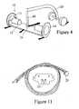
- Fig. 11illustrates the Sharp GP2D12 sensor 27 which is described as providing less influence on the color of reflected objects, reflectivity. With the sensor 27, an external control circuit is unnecessary and the sensor 27 is very low cost.
- the GP2D12O infrared sensor 27has special lenses and takes a continuous distance reading and reports the distance as an analog voltage with a distance range of 4cm to 30cm.
- the interfaceis 3-wire with power, ground and the output voltage and requires a JST 3-pin connector 29 that is shown in Fig. 11 .
- the measurements from the sensor 27are provided to the controller 16 times a second as the robotic vehicle 10 travels.
- the sensor 27reports the distance as an analog signal accurate to 1/5" and this is utilized, combined with the known geometry of the sensor 27 on the robotic vehicle 10 to determine a sequence of positions relative to the robot based coordinate system where this wall should be.
- a statistical methodto eliminate anomalous readings may be used to determine if the data meets the criterion for a wall (e.g. "this section should be straight"). Then the following is determined: 1) the distance over to the wall and 2) the orientation of the wall. This orientation is compared to the expected orientation of the wall knowing where the robotic vehicle 10 believes it is with respect to its internal map.
- the calculated position of the wallappears to be radically different from the previous expected position it is assumed a measurement error occurred and the data can be rejected.
- the value of what is "radically different”can be selected as known in the art. If the correction is within reason, it is assumed that the sensor data is right and the robotic vehicle's ded-reckoning based assumption about the position is not, and the new orientation is used to update the assumption about the vehicle position and orientation within the map (i.e. the robot's assumed orientation is calibrated).
- An additional featuremaybe added where the vehicle 10 also "looks" at the ending or start of the wall to determine the other offset, (e.g. the forward/backward position). Again, the robotic vehicle 10 will do this as often as possible, sometimes every ten feet.
- This methodmay be modified to be used on nonlinear continuous surfaces as well.
- the checkpointsmay be positioned on a wall having a known radius of curvature. Additionally, it is important to note that the checkpoints represent positions on a given wall, but no physical modification of the existing wall is required for utilizing the present invention. In this respect the checkpoints may be considered to be virtual checkpoints.
- a key featureis the fact that the robotic vehicle 10 is mainly measuring orientation error and the fact that there are discrete measuring places or “checkpoints" that are “set up” then used comparatively.
- the use of a range sensor 27is very effective for picking up orientation error with relatively little a sensor investment.
- the robot 10needs both a mechanical connection to the cart 20 that it is pulling and an electrical connection if the cart 20 is to include any input or output devices associated with the robot 10. These can include directional controls (e.g. a joystick controller for movement) for controlling movement of the robot 10, sensors for assisting in detecting obstacles or position, emergency override (e.g. a stop button), a standard computer of touch screen interface, audible or visual indicators (e.g. light and sound systems), supplemental battery power for the robot 10, or the like.
- the electrical connectionhas two purposes, one to pass information back and forth between processors in each device, and the other to pass power in the case where the battery for driving the robot motors 30 is located in the cart 20 not the robot 10.
- the present inventionprovides a novel connector that takes advantage of the mechanical loads to create excellent electrical current carrying capacity all through the same device.
- the inventioncan pass up to 20 amps of current through the connection while maintaining strong enough surface contact to avoid any arcing that would eventually wear the materials out.
- This methodhas the benefit of not only maintaining great contact but it also keeps the two electrical poles mechanically isolated from each other because they are in different planes. Standard ring approaches always have potential shorting problems during insertion and removal of the post into the connector while this method eliminates this problem.
- One electrical connection between the cart 20 and the robot 10is made between a bolt 42 at the end of wagon or cart attaching post 44 and the receiving metal support 46 on the robot 10 in a bore within the robot body and housing.
- the weight of the cart 20 that is carried by the robot 10maintains this connection.
- This weightshould be at least half of the weight of the cart 20, since increased weight on the robot 10 reduces accumulating positioning error due to a reduction in wheel slippage.
- the second electrical connectionis between the steel tube 48 of the post and a brass bushing 50 in the robot 10. The tight fit between the tube 48 and the bushing 50 and the forces exerted through pulling of the cart 20 maintain this electrical connection.
- the post 44includes a thrust bearing at the end of the tube 48 in the bushing 50 which serves as the load transfer point between the cart 20 and the robot vehicle 10.
- a bearing sleeveis in the bushing 50 between the tube 48 and the bushing 50 to allow free rotation of between the robot vehicle 10 and the cart 20 (and the cart attaching post 44 which is secured thereto through the post connector flange).
- Three copper ringsare surrounding the tube 48, insulated from each other and the tube 48.
- a brush contactis biased into contact with a selected copper ring by a steel spring support attached to the body 12 through an upper or lower post support member respectively.
- the upper and lower post supportmay be considered to define a bore in the body 12 for the post 44.
- Another brush contactmay be biased against the tube 48 to provide a ground contact.
- the copper rings and the brush contacts which engage themform a slip ring type electrical connection for electrically coupling the robotic vehicle 20 with the cart 20 (wires from the brush contacts to the controller 16 and from the cart 20 through the tube 48 to the rings 146 are not shown).
- An additional copper ring and brush contactsmay be added if additional electrical connections are desired.
- the use of the central post 44will avoid the positioning errors that can be introduced with a separate electrical and mechanical connection. For example a separate electrical cord between the cart 20 and the robot 10 may wrap around a mechanical connection as the robot turns relative to the cart 20 eventually restricting further rotational movement there between and creating large positional errors.
- connection 24 above the bushing 50will be an ellipse or elongated along the vehicle wheel axis such as in the upper post support. The ellipse or elongation is along the wheel axles.
- the present robot 10is of the two wheeled counter-rotating type and any heading change is calculated by knowing how much more one wheel 14 has turned than another. Slippage is difficult to measure. If the robot 10 could measure it, then it could calculate the impact on the heading by knowing how much more one wheel 14 has slipped than the other, which is described in some of the prior art patents.
- the present strategyis to instead try to keep the slippage minimal and equal between the wheels 14 by using the following methods:
- the swivel or cart attaching mechanism 24 for the robot 10has compliance of plus and minus three degrees about a vector pointing in the forward travel direction of the robot 10.
- the post 44can pivot in a plane defined by the wheel 14 axles.
- This complianceallows the robot 10 to have one wheel 14 a half inch higher than the other wheel 14 while still distributing the loads nearly evenly between them. This compensates for unevenness of the floor, which in a perfectly stiff connection (i.e. no compliance) could shift all the load to a single wheel 10 like a car with three wheels on the curb and the fourth hanging off over the curb.
- This side to side swivelis a key feature of the present invention, and the lack of which causes other robots to not work. There are two reasons: 1) floors not being perfectly level (in fact, it has been observed that variations of 20" side to side often exist when traveling straight forward 15 feet); and 2) when turning, the centripetal force of the robot and cart places more load on the outside wheel than the inside wheel if this swivel is not present and this would cause significant error. The only way this is solved is putting the attachment low (i.e. the position of the load transferring bushing 50) and with swivel about a forward pointing axis. Otherwise, there are times when all the weight would be on one wheel 14 and the creep that occurs between the floor and the tread would be drastically uneven causing large errors.
- the robot 10is designed to increase Fd as much as possible by putting as much of the weight of its cargo over the robot 10 as practical.
- the robot 10 designalso tries to minimize Fl by reducing the rolling resistance and keeping the accelerations low.
- the trickier partis that the design of the robot 10 also tries to keep Fl and Fd as close to the same on each the left and right wheel 14 as possible so that on average (not constantly because there is still the random element which is inconsistent between the wheels 14) but on average, the slip that does occur is the same on both wheels 14 so that although there is some positional error generated, the heading error accumulation is minimal.
- the robot 10 designdoes this by not only attaching the cart 20 in the center between the wheels 14 through a near frictionless bearing which keeps the lateral forces equal between the wheels 10 but the invention also attaches the cart load as low as possible on the robot 10 which has the effect of keeping the downward forces as even as possible because the cart 20 isn't attempting to tip the robot 10 over as it is pulled around corners, the source of the greatest orientation error accumulation.
- the load transfer point between the post and the robot 10i.e. the bushing 50
- the height of the load transfer pointis less than 1/5 and preferably less than 1/10 of the wheel base.
- the robotic vehicle 10 of the present inventionprovides a number of unique designs for the wheels 14 as shown in figures 5, 6a and 6b .
- the sticky urethane, or polyurethane, coating treadbeing provided as thin as possible over the hardened annular disk 60 will minimize the wheel radius variation.
- the radius variation of the wheel 14is due to compression of the urethane coating.
- the thin coating of urethaneis selected such that the compression of the wheels 14 under load (i.e. the change in radius of the wheel due to compression of the urethane coating) is less than 2% of the wheel radius, and preferably less than 1% of the wheel radius.
- the load referred tois more precisely the change in load between a robot and attached unloaded cart and the robot and attached loaded cart.
- the robot 10 and attached unloaded cart 20are considered a base line, or unloaded, state for the wheels 14. This is in contrast to prior art dirigible wheels that compress, in operation, to a large fraction of the wheel radius, resulting in significant deduced reckoning error. Additionally, the annular wheel contact patch is provided as narrow as possible, on the order of 0.20 in, to keep the effective width between the wheels 14 as constant as possible. A large contact patch for the wheels will result in a variation of the effective wheel base. In the present invention the width of the contact patch of each wheel 14 is less than 1.5%, and preferably less than 1% of the wheel base between the wheels.
- the narrow wheelsallow the variations in the effective wheel base to remain relatively small, specifically the change in the wheel base of the the robot 10 will be less than 2%, possibly even less than 0.5%.
- These wheel design featuresminimize deduced reckoning error as discussed above.
- the system of the present inventionis designed to provide the cargo weight mainly over the robot 10 to maximize traction and minimize wheel slippage, minimizing wheel error.
- the attachment of the cart load as low as possiblewill keep the downward force as even as possible so that the cart is not attempting to tip the robot over as being pulled around corners, as discussed above. All of these design considerations improve the deduced reckoning of the present invention.
- the robotic vehicle 10 of the present inventionprovides an automatic, labor-saving indoor freight hauler that is capable of hauling up to 500 pounds of goods on a cart 20 and can fit into a suitcase.
- the robotic vehicle 10is generally the size of a suit box, about 20 inches wide and 8 inches tall.
- the vehicle 10can effectively be described as a circuit board on wheels 14 mounted on a metal chassis or body 12 with a set of batteries 18, a PC mother board and with attached sensors 27, 28.
- the described vehicle 10can perform rounds stopping at a series of stations or can do fetch and deliver errands and can haul a variety of carts 20 to the appropriate job. It is anticipated that the robotic vehicle 10 will be controlled with a graphical user interface.
- the carts 10can be modified to include the battery as discussed above, or other interface connections such as a steerable joystick and the like.
- Another key feature of the present inventionis the ability to easily retrofit existing carts 20 to be utilized with the robot 10 of the present invention. The retrofitting of existing carts 20 would generally only require the addition of an appropriate post 44. Additional elements such as supplemental batteries, input devices such as steering joystick or a keyboard, or sensors may also be retrofitted onto the existing carts 20.
Landscapes
- Engineering & Computer Science (AREA)
- Radar, Positioning & Navigation (AREA)
- Physics & Mathematics (AREA)
- Aviation & Aerospace Engineering (AREA)
- Remote Sensing (AREA)
- General Physics & Mathematics (AREA)
- Automation & Control Theory (AREA)
- Electromagnetism (AREA)
- Control Of Position, Course, Altitude, Or Attitude Of Moving Bodies (AREA)
- Manipulator (AREA)
Description
- The present invention relates to robotic cart pulling vehicles for automated hauling of materials indoors. More specifically, the present invention relates to a cart pulling deduced reckoning guided mobile robot system.
- Robotic and automated vehicles for delivering or transporting material indoors have been developed and utilized in a number of applications. One well-known application is the automated mail delivery vehicles and robots. An example of such a mail delivery vehicle is manufactured by the Mailmobile division of Bell and Howell. Rather than being an independent robotic vehicle, this is an automatic guided vehicle following a prepared track, such as a painted ultraviolet track positioned on the floor. Another example is produced by FMC which manufactures an automated transport and logistics integration system, referred to as ATLIS, for moving specially designed carts in indoor environments, such as hospitals. To pick up a cart, the ATLIS vehicle positions itself under the cart, the deck of the vehicle is equipped with an electric lift which extends to raise the cart from the floor. The ATLIS system is generally a wire-guided system requiring a guide wire to be permanently installed in the floor.
- In the hospital environment, a company referred to as Helpmate Robotics developed a robotic courier for hospitals. The robotic courier was essentially a wheeled cabinet. This hospital robotic courier is currently being offered by the Pyxis division of Cardinal Heath, Inc. The robotic courier has many disadvantages, the first of which is that it is overly expensive, and a second is that it is only useful for transporting materials that can fit in the associated cabinet installed with the robot.
- A wide variety of prior art robotic and automated vehicles are discussed in the patent literature. For example,
U.S. Patent No. 4,746,977 to White is directed to a remotely operated steerable vehicle.U.S. Patent No. 4,871,172 to Kanayama is directed toward a mobile robot and a control therefore.U.S. Patent No. 5,488,277 to Nishikawa et al. discloses a collection of mobile robots and a control station for the plurality of mobile robots.U.S. Patent No. 5,175,480 to McKeefery et al. is directed toward an automated guided vehicle.U.S. Patent No. 5,461,292 Zondlo discloses a remote controlled two-wheeled lawn mowing vehicle.U.S. Patent No. 5,545,960 to Ishikawa is directed toward a mobile machine following a predetermined path.U.S. Patent No. 5,819,863 to Zollinger et al. is directed toward a robotic vehicle including a support structure.U.S. Patent No. 5,709,007 to Chiang discloses a remote control vacuum having a remote control drive unit or cart to which a portable vacuum unit is removable attached. - Further the patent literature discussed a wide variety of navigational, error control, and obstacle detection systems such as discussed in the following patents that are incorporated herein by reference.
U.S. Patent No. 5,276,618 to Everett, Jr. is directed toward a doorway transit navigational referencing system for a robot vehicle. This system utilizes a plurality of sensors for sensing known reference objects to obtain orientation information.U.S. Patent No. 5,324,948 to Dudar et al. discloses a robot following a predetermined path and uses the collection of a series of distinct data points between the sensor and a wall in order to recognize the object as a wall. Additionally, the patent discloses that if a door or other wall feature is found, the robot will ignore the new data points and use ded-reckoning until a valid "wall" is found.U.S. Patent No. 5,402,344 to Reister et al. is directed toward a method for independently controlling steerable drive wheels of the vehicle with two or more such wheels. The system provides a method for determining the wheel slip associated with a given wheel.U.S. Patent No. 5,548,511 to Bancroft discloses a robotic cleaning apparatus in which the robot measures and records the distances to the left and right boundaries as it travels to determine or map the area. Subsequent to mapping the area, it will determine the path for cleaning the area with the robot following a predetermined path in such cleaning. The Bancroft patent does disclose that encoders provide ded-reckoning navigation while the sensors provide corrections to errors caused by, for example, slippage of the wheels. The precise correction method utilized is not discussed. Additionally disclosed is that the sensors can be advantageously used to follow variations in the boundary of the area that deviate from dimensions measured in the learning phase and to avoid obstacles in the area. The Bancroft patent additionally discusses dealing with areas or variations by using the mode of the measurements obtained by the sensors, that is the value of the measurement that occurs most often. Additionally, the robot ignores measurements that are greater than a maximum range of the sensor.U.S. Patent No. 5,556,356 to Kim discloses a mobile robot incorporating a position correcting system. Included in the system is a distance detecting mechanism or sensor detecting the distance of separation between the robot and a separate positioning correcting mechanism positioned within a wall. The position correcting mechanism in the wall can include an infrared receiving unit and a transmitting unit which is selectively activated by the robot as is passes to send appropriate control compensating signals to the robot.U.S. Patent No. 5,559,696 to Borenstein discloses a mobile robot with an internal positioning error correction system utilized for correcting non-systematic deduced reckoning errors and discloses a robot with a trailer hitch connected to the center of the robot.U.S. Patent No. 5,652,489 to Kawakami is directed toward a mobile robot control system wherein the robots move on a predetermined route in a given area including optical detection sensors.U.S. Patent No. 5,680,306 to Shin et al. discloses a robotic vehicle primarily utilizing global positioning systems (GPS). The patent additionally discloses the use of deduced reckoning to supplement the GPS system.U.S. Patent No. 5,684,696 to Rao et al. discloses a system and method for enabling an autonomous vehicle to follow a desired path. The system utilizes a combination of a GPS and an initial reference unit (IRU) integrated together.U.S. Patent No. 5,687,294 to Jeong is directed toward a control system for a mobile robot including obstacle detection and correction of positioning and directional errors.U.S. Patent No. 5,739,657 to Takayama et al. is directed toward a control system for controlling the motion of an omni-directional robotic vehicle.U.S. Patent No. 5,819,008 to Asama et al. is directed toward a mobile robot sensor system for a system of multiple robots in a given environment. The robots utilize infrared sensors for communicating with other robots for avoiding other roots in the environment.U.S. Patent No. 5,942,869 to Katou et al. discloses an automated robotic vehicle utilizing caterpillar treads. Additionally disclosed is the use of supersonic or ultrasonic sensors for obstacle detection.U.S. Patent No. 6,041,274 to Onishi et al. is directed toward a positional deviation detecting device for a robot or working machine which utilizes a pick-up sensor for detecting the image on a floor.- The above discussed prior art does not effectively provide for a cart pulling or cart pulling robotic vehicle that would be useful for hauling materials on a variety of carts or wagons indoors. A cart pulling ded-reckoning guided robotic vehicle is disclosed in
U.S. Patent No. 6,046,565 (hereinafter "the '565 patent") that is also incorporated herein by reference. The '565 patent discloses a robotic vehicle with a deduced reckoning positioning system having a center mounted harness, or attachment mechanism, on the robot body for coupling a cart or wagon to be pulled thereby. The '565 patent teaches that the system calibrates the absolute position of the robotic vehicle relative to a fixed reference marker, such as a wall, to eliminate the accumulated error in the calculated position of the robotic vehicle. Additionally, the '565 patent discloses that a single reference wall may be used to eliminate the error in selected two parameters. With regard to the attachment mechanism or harness, the '565 patent suggests that the ratio of the height of the harness joint above the floor to the axle width should be as low as possible to better approximate the ideal planar situation. The '565 patent does not discuss the attachment mechanism further. - All of the above-discussed prior art has substantial disadvantages. It is the object of the present invention to improve upon the prior art and provide a cart or wagon pulling deduced reckoning guide mobile robot system useful for industrial applications, such as in hospitals and like. In this regard, the present application can be considered an improvement over some of the fundamental concepts disclosed in the '565 patent.
- The objects of the present invention are achieved with a robotic cart pulling vehicle including a positioning error reducing system for reducing accumulated error in the ded-reckoning navigational system according to the present invention. The positioning error reducing system includes at least one of a low load transfer point of the cart attaching mechanism, a floor variation compliance structure whereby the drive wheels maintain a substantially even distribution of load over minor surface variations, a minimal wheel contact surface structure, a calibration structure using at least one proximity sensor mounted on the robot body, and an electrical and mechanical connection between the cart and the robotic vehicle formed with a cart attaching post positioned at a midpoint of the wheel base.
- Several of the improvements of the current invention forming the positioning error reducing system relate to the connection between the robot and the cart being pulled. Specifically, the mechanical connection between the cart and robot body is provided with a low force transfer point for reducing the deduced reckoning error. The force transfer point is preferably as low as possible, at least below the wheel axle. Mathematical descriptions for the low attachment location is having a height to base ratio of less than 1/5, or even less than 1/10, wherein height is the height of the attachment point above the surface defined by the bottom of the driven wheels and the base is the distance between the driven wheels along the wheel axle. A second improvement in the mechanical connection is the provision of a freedom of motion about the travel axle, also referred to as a floor variation compliance structure. A compliance of about 3 degrees or so between the robot and the cart attaching post allows one wheel to be vertically moved a certain distance while still maintaining an even distribution of force between the wheels. This allows the robot to compensate for uneven floors, doorjambs and other features without adversely affecting the deduced reckoning position control. A further feature of the mechanical connection is the use of the cart attaching post as both the mechanical connection as an electrical connection point between the robotic vehicle and the wagon or cart being pulled. The electrical connection allows information to pass back and forth between the processors in each device as well as allowing power to pass back and forth between either device. This will allow the battery for driving the robot to be located in the cart as opposed to in the robot body. The mechanical connection, finally, may include some compliance in the upper portion thereof, to assure that the mechanical transfer of force is at the lower portion for the reasons discussed above.
- Another aspect of the positioning error reducing system for reducing accumulated error in the ded-reckoning navigational system according to the present invention is the calibration system for zeroing out deduced reckoning error using proximity sensors mounted on the vehicle body. The calibration system of the present invention places checkpoints along walls that have straight sections longer than a predetermined amount, such as two feet. The present system will place as many of these checkpoints as possible along any vertical structure meeting the minimum limitation requirement that is found in the robot's known world. In operation, when the robot is traveling parallel to a wall with a checkpoint, a conventional infrared proximity sensor is utilized to measure a series of distances to the wall. This generates a series of data points relative to the checkpoints and a statistical method is used to determine if the data meets the criteria for the wall. If this series of updated positions meets reasonable expectation, the data is utilized to update the robot position and, more importantly, the robot orientation.
- A further modification in the robotic vehicle forming the positioning error reducing system for reducing accumulated error in the ded-reckoning navigational system is the wheel design for improved ded reckoning accuracy. The present wheel design is created to keep the variation in the wheel radius and the width between the wheels under 2%, or even 0.5 %. The wheel design of the present invention is intended to minimize the contact patch width provided by the wheel as well as minimize the variation in the compression of the wheel relative to load on the vehicle. To accomplish this, the wheel is provided with a solid stiff circular core provided with an outer annular coating providing the tire tread. In cross-section, the tread may converge to an annular contact area of minimum width, other minimal width annular contact areas are also possible.
- These and other advantages of the present invention will be clarified in the detailed description of the preferred embodiment taken together with the attached drawings.
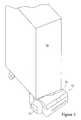
Fig. 1 is a perspective schematic view of a robotic cart pulling vehicle according to the present invention;Fig. 2 is a perspective schematic view, partially broken away, of the robotic vehicle illustrated inFig. 1 ;Fig. 3 is a perspective schematic view of the robotic vehicle ofFig. 1 attached to and pulling a cart;Fig. 4 is a schematic perspective view of the robotic vehicle and cart ofFig. 3 illustrating the forces on the vehicle and cart;Fig. 5 is a plan view of a wheel of the robotic vehicle of the present invention;Fig. 6a is a schematic cross-sectional view of the wheel ofFig. 5 and Fig. 6b is an enlarged cross sectional view of a modified wheel hub;Fig. 7 is a sectional view illustrating a floor variation compliance structure of the robotic vehicle ofFig. 1 ;Fig. 8a is a schematic sectional side view of an electromechanical connection between the robotic vehicle and cart of the present invention;Fig. 9a is a front side view of the cart attaching connection illustrated inFig. 8a ;Fig. 10 is a top view of the harness connection shown inFig. 8a ; andFig. 11 is a plan view of a range sensor utilized in the correction of ded-reckoning error.- The
robotic vehicle 10 or robot of the present invention is shown inFigs 1 and 2 . Therobotic vehicle 10 is essentially a chassis orbody 12 with two co-axial drivenwheels 14. Thebody 12 houses the circuit board orcomputer controller 16 for thevehicle 10. Abattery pack 18 is also on thebody 12 although therobotic vehicle 10 could also be powered through a battery on an attached cart orcart 20 being pulled by therobotic vehicle 10. Acart attachment mechanism 24 is centered on thebody 12 midway between thewheels 14 essentially along and above the axels of thewheels 14. Ahousing 26 covers thebody 12 and includes a collection ofsensors range sensors 27 are used for correction of positioning and orientation error as described below andsonar sensors 28 are used for obstacle detection as generally known in the art. Therobotic vehicle 10 can have a variety of further features well known in the industry, such as audible outputs to announce its proximity. The present application is only focused on the unique aspects of the presentrobotic vehicle 10 not readily known to those in the art. Specifically the present application is focused on a roboticcart pulling vehicle 10 including a positioning error reducing system for reducing accumulated error in the ded-reckoning navigational system. The positioning error reducing system includes at least one of a low load transfer point of thecart attaching mechanism 24, a floor variation compliance structure whereby thedrive wheels 14 maintain a substantially even distribution of load over minor surface variations, a minimal wheel contact surface structure, a calibration structure using at least one proximity sensor mounted on therobot body 12, and an electrical and mechanical connection between the cart and the robotic vehicle formed with a cart attaching post positioned at a midpoint of the wheel base. - A first aspect of the positioning error reducing system of the present invention relates to the use of the
range sensors 27 and associated checkpoints in a calibration system to correct and eliminate ded-reckoning error. The most critical task for any mobile robotic vehicle is to know where it is with respect to some map (i.e. it's world map). Without this information the robotic vehicle can't calculate how to get anywhere. The robotic vehicle would not even know which way it's facing so it can't even start trying to travel to its destination. Obviously, if the robotic vehicle can't get where the operator wants it to go it can't perform much useful work. This is the main thrust of mobile robotics and it has been called the "navigation riddle." - The ultimate goal in addressing this issue may be some external system that keeps track of where the robotic vehicle is and which way it's facing and keeps the robotic vehicle informed. GPS is close to this goal, but it doesn't tell the robotic vehicle which way it's facing, it only works outside, and it isn't accurate enough to guide a robotic vehicle through a doorway. In lieu of this ideal system, some robots instead guess where they are from the amount they've turned each wheel. It's called ded-reckoning. This method is inherently flawed; therefore many robotic vehicles using deduced reckoning then correct any error that accumulates with any of a wide variety of sensor methods.
- Most research effort is focused on the sensors for correcting the ded-reckoning error. One advance in the field with the present invention is to instead focus on the cause of the errors and the minimization and/or elimination of them. The present methods employed in the instant invention reduce ded-reckoning error from a typical 7% found in prior art robotic robots using deduced reckoning to less than 1% in the present invention.
- Lateral accuracy in the known robotic vehicle position is hard to achieve because it depends on accurate knowledge of the heading of the robotic vehicle. If the robotic vehicle heading is just 6 degrees off (i.e. 6 degrees difference between the actual heading and the estimated heading assumed by the vehicle), traveling 10 feet forward will result in a lateral error of 1 foot. The robotic vehicle is 1 foot away from where it believes that it is, with the errors continuing to compound until corrected. The key to the effectiveness of any ded-reckoning system is maintaining the heading information as accurately as possible. Typical robot systems accumulate 10 to 16 degrees of heading error in executing a 180 degree rotation; the present robotic vehicle generates only 2.5 degrees of error executing a 180 degree rotation.
- As discussed above, ded-reckoning systems accumulate error no matter how well they are designed and the present system still accumulates some small amount of error. The present invention incorporates a system for zeroing out accumulated error that utilize pre established checkpoints and may be referred to as light whiskertm checkpoints. A map of the world is held internally by the
robotic vehicle 10 as understood by those in the art. On this map, virtual light whiskertm checkpoints" (LWC) are positioned along walls that have straight sections longer than a predetermined minimum amount, such as 2 feet. As many LWC's as can fit are placed along any wall that meets the minimum (e.g. 2') straight section requirement. When therobotic vehicle 10 is traveling parallel to a wall with a LWC, aconventional range sensor 27, such as a Sharp GP2D12 infrared sensor, is used to look sideways at the wall and measure a series of distances to the wall.Fig. 11 illustrates theSharp GP2D12 sensor 27 which is described as providing less influence on the color of reflected objects, reflectivity. With thesensor 27, an external control circuit is unnecessary and thesensor 27 is very low cost. The GP2D12Oinfrared sensor 27 has special lenses and takes a continuous distance reading and reports the distance as an analog voltage with a distance range of 4cm to 30cm. The interface is 3-wire with power, ground and the output voltage and requires a JST 3-pin connector 29 that is shown inFig. 11 . - The measurements from the
sensor 27 are provided to thecontroller 16 times a second as therobotic vehicle 10 travels. Thesensor 27 reports the distance as an analog signal accurate to 1/5" and this is utilized, combined with the known geometry of thesensor 27 on therobotic vehicle 10 to determine a sequence of positions relative to the robot based coordinate system where this wall should be. Using this set of positions, a statistical method (to eliminate anomalous readings) may be used to determine if the data meets the criterion for a wall (e.g. "this section should be straight"). Then the following is determined: 1) the distance over to the wall and 2) the orientation of the wall. This orientation is compared to the expected orientation of the wall knowing where therobotic vehicle 10 believes it is with respect to its internal map. If the calculated position of the wall appears to be radically different from the previous expected position it is assumed a measurement error occurred and the data can be rejected. The value of what is "radically different" can be selected as known in the art. If the correction is within reason, it is assumed that the sensor data is right and the robotic vehicle's ded-reckoning based assumption about the position is not, and the new orientation is used to update the assumption about the vehicle position and orientation within the map (i.e. the robot's assumed orientation is calibrated). An additional feature maybe added where thevehicle 10 also "looks" at the ending or start of the wall to determine the other offset, (e.g. the forward/backward position). Again, therobotic vehicle 10 will do this as often as possible, sometimes every ten feet. This method may be modified to be used on nonlinear continuous surfaces as well. For example, the checkpoints may be positioned on a wall having a known radius of curvature. Additionally, it is important to note that the checkpoints represent positions on a given wall, but no physical modification of the existing wall is required for utilizing the present invention. In this respect the checkpoints may be considered to be virtual checkpoints. - A key feature is the fact that the
robotic vehicle 10 is mainly measuring orientation error and the fact that there are discrete measuring places or "checkpoints" that are "set up" then used comparatively. The use of arange sensor 27 is very effective for picking up orientation error with relatively little a sensor investment. - The use of an electrical connection through the mechanical connection of the
cart attaching mechanism 24 betweencart 20 and robot orrobotic vehicle 10 is another key feature of the positioning error reducing system for reducing accumulated error in the ded-reckoning navigational system according to the present invention. This connection allows for the passage of both information and power between thecart 20 and therobot 10 as well as the transferring of the mechanical forces for towing of thecart 20. - The
robot 10 needs both a mechanical connection to thecart 20 that it is pulling and an electrical connection if thecart 20 is to include any input or output devices associated with therobot 10. These can include directional controls (e.g. a joystick controller for movement) for controlling movement of therobot 10, sensors for assisting in detecting obstacles or position, emergency override (e.g. a stop button), a standard computer of touch screen interface, audible or visual indicators (e.g. light and sound systems), supplemental battery power for therobot 10, or the like. The electrical connection has two purposes, one to pass information back and forth between processors in each device, and the other to pass power in the case where the battery for driving the robot motors 30 is located in thecart 20 not therobot 10. For this purpose the present invention provides a novel connector that takes advantage of the mechanical loads to create excellent electrical current carrying capacity all through the same device. - Essentially, there are two loads exerted on the
robot 10 by thecart 20, one is downward where therobot 10 is holding up at least half of thecart 20, and the other is lateral, the one that actually pulls thecart 20 along. The downward load on therobot 10 is supported by one electrical connection and the lateral is supported by the return electrical connection. In this way, the invention can pass up to 20 amps of current through the connection while maintaining strong enough surface contact to avoid any arcing that would eventually wear the materials out. This method has the benefit of not only maintaining great contact but it also keeps the two electrical poles mechanically isolated from each other because they are in different planes. Standard ring approaches always have potential shorting problems during insertion and removal of the post into the connector while this method eliminates this problem. The details of this arrangement are found infigures 8a, 9a and 10 . One electrical connection between thecart 20 and therobot 10 is made between abolt 42 at the end of wagon orcart attaching post 44 and the receivingmetal support 46 on therobot 10 in a bore within the robot body and housing. The weight of thecart 20 that is carried by therobot 10 maintains this connection. This weight should be at least half of the weight of thecart 20, since increased weight on therobot 10 reduces accumulating positioning error due to a reduction in wheel slippage. The second electrical connection is between thesteel tube 48 of the post and abrass bushing 50 in therobot 10. The tight fit between thetube 48 and thebushing 50 and the forces exerted through pulling of thecart 20 maintain this electrical connection. - Hereafter an alternative construction of the
post 44 which still provides for both a mechanical and an electrical connection between therobotic vehicle 10 and thecart 20 will be described, with reference toUS provisional application serial number 60/407,117 filed August 30, 2002bolt 42 and themetal support 46 due to high loading. Specifically thepost 44 includes a thrust bearing at the end of thetube 48 in thebushing 50 which serves as the load transfer point between thecart 20 and therobot vehicle 10. A bearing sleeve is in thebushing 50 between thetube 48 and thebushing 50 to allow free rotation of between therobot vehicle 10 and the cart 20 (and thecart attaching post 44 which is secured thereto through the post connector flange). Three copper rings are surrounding thetube 48, insulated from each other and thetube 48. A brush contact is biased into contact with a selected copper ring by a steel spring support attached to thebody 12 through an upper or lower post support member respectively. The upper and lower post support may be considered to define a bore in thebody 12 for thepost 44. Another brush contact may be biased against thetube 48 to provide a ground contact. The copper rings and the brush contacts which engage them form a slip ring type electrical connection for electrically coupling therobotic vehicle 20 with the cart 20 (wires from the brush contacts to thecontroller 16 and from thecart 20 through thetube 48 to the rings 146 are not shown). An additional copper ring and brush contacts may be added if additional electrical connections are desired. The use of thecentral post 44 will avoid the positioning errors that can be introduced with a separate electrical and mechanical connection. For example a separate electrical cord between thecart 20 and therobot 10 may wrap around a mechanical connection as the robot turns relative to thecart 20 eventually restricting further rotational movement there between and creating large positional errors. - Another key feature of the positioning error reducing system for reducing accumulated error in the ded-reckoning navigational system according to the present invention is the use of the mechanical/electrical connection between
cart 20 androbot 10 that is rigid front to back but allows a certain amount side to side rotation, such as three degrees, forming a floor variation compliance structure. In this regard theconnection 24 above thebushing 50 will be an ellipse or elongated along the vehicle wheel axis such as in the upper post support. The ellipse or elongation is along the wheel axles. This compliance is shown infigure 7 through the tilting of thepost 44 relative to therobot 10, whereby eachdrive wheel 14 is mounted to saidrobot body 12 in a manner allowing vertical movement of saidwheel 14 relative to thecart attaching post 44 in the amount of at least three degrees measured from a center point of the collinear drive wheel axles. In this manner thecollinear drive wheels 14 maintain a substantially even distribution of load over minor surface variations. - There is always some amount of slippage occurring between the
wheels 14 and the floor. Thepresent robot 10 is of the two wheeled counter-rotating type and any heading change is calculated by knowing how much more onewheel 14 has turned than another. Slippage is difficult to measure. If therobot 10 could measure it, then it could calculate the impact on the heading by knowing how much more onewheel 14 has slipped than the other, which is described in some of the prior art patents. - The present strategy is to instead try to keep the slippage minimal and equal between the
wheels 14 by using the following methods: - a) to minimize the slippage on smooth surface floors the
robot 10 uses urethane coating 54 (such as on in line skate wheels) on thewheels 14 which has an incredibly large coefficient of friction while also being extremely durable; - b) the wagon or
cart 20 is attached to therobot 10 in the center between thewheels 14 through a near frictionless bearing (i.e. thepost 44 can rotate in the attaching mechanism 24) which keeps the lateral forces equal between thewheels 14; - c) the wagon or
cart 20 is attached to the robot 10 (i.e. the cart loading forces are transferred) as low as possible to maintain the cart load as low as possible on the robot 10 (the forces being transferred through the bushing 50) which has the effect of keeping the downward forces as even as possible because the wagon orcart 20 isn't attempting to tip therobot 10 over as it is pulled around corners( this is believed to be the source of the greatest orientation error accumulation); - d) the
robot 10 is designed to put as much of the weight of its cargo (the wagon or cart 20) over therobot 10 as possible; - e) finally the
robot 10 is designed to reduce the rolling resistance and keeping the accelerations low. - As discussed above, the swivel or
cart attaching mechanism 24 for therobot 10 has compliance of plus and minus three degrees about a vector pointing in the forward travel direction of therobot 10. In other words thepost 44 can pivot in a plane defined by thewheel 14 axles. This compliance allows therobot 10 to have one wheel 14 a half inch higher than theother wheel 14 while still distributing the loads nearly evenly between them. This compensates for unevenness of the floor, which in a perfectly stiff connection (i.e. no compliance) could shift all the load to asingle wheel 10 like a car with three wheels on the curb and the fourth hanging off over the curb. This is especially critical in navigating over door jambs which can be a half inch high where therobot 10 could cross them at a diagonal essentially leaving onewheel 14 completely off the floor without this feature. This side to side swivel is a key feature of the present invention, and the lack of which causes other robots to not work. There are two reasons: 1) floors not being perfectly level (in fact, it has been observed that variations of 20" side to side often exist when traveling straight forward 15 feet); and 2) when turning, the centripetal force of the robot and cart places more load on the outside wheel than the inside wheel if this swivel is not present and this would cause significant error. The only way this is solved is putting the attachment low (i.e. the position of the load transferring bushing 50) and with swivel about a forward pointing axis. Otherwise, there are times when all the weight would be on onewheel 14 and the creep that occurs between the floor and the tread would be drastically uneven causing large errors. - Additionally, to keep the slip equal between the
wheels 14 the invention essentially uses a strategy of keeping the forces equal between them. Slippage is proportional to lateral forces (forces in the plane of the floor Fl) and inversely proportional to the downward force (Fd) the good force which maintains the friction between the wheel. There is also a random slippage caused by things like dirt on the floor that we call F (random noise) and over which there is no control.
- To minimize the slippage the
robot 10 is designed to increase Fd as much as possible by putting as much of the weight of its cargo over therobot 10 as practical. Therobot 10 design also tries to minimize Fl by reducing the rolling resistance and keeping the accelerations low. The trickier part is that the design of therobot 10 also tries to keep Fl and Fd as close to the same on each the left andright wheel 14 as possible so that on average (not constantly because there is still the random element which is inconsistent between the wheels 14) but on average, the slip that does occur is the same on bothwheels 14 so that although there is some positional error generated, the heading error accumulation is minimal. Therobot 10 design does this by not only attaching thecart 20 in the center between thewheels 14 through a near frictionless bearing which keeps the lateral forces equal between thewheels 10 but the invention also attaches the cart load as low as possible on therobot 10 which has the effect of keeping the downward forces as even as possible because thecart 20 isn't attempting to tip therobot 10 over as it is pulled around corners, the source of the greatest orientation error accumulation. The load transfer point between the post and the robot 10 (i.e. the bushing 50) is below the wheel axle. More significantly the height of the load transfer point is less than 1/5 and preferably less than 1/10 of the wheel base. - The
robotic vehicle 10 of the present invention provides a number of unique designs for thewheels 14 as shown infigures 5, 6a and 6b . Regarding the wheel design, the sticky urethane, or polyurethane, coating tread being provided as thin as possible over the hardenedannular disk 60 will minimize the wheel radius variation. The radius variation of thewheel 14 is due to compression of the urethane coating. In the present invention the thin coating of urethane is selected such that the compression of thewheels 14 under load (i.e. the change in radius of the wheel due to compression of the urethane coating) is less than 2% of the wheel radius, and preferably less than 1% of the wheel radius. The load referred to is more precisely the change in load between a robot and attached unloaded cart and the robot and attached loaded cart. Therobot 10 and attached unloadedcart 20 are considered a base line, or unloaded, state for thewheels 14. This is in contrast to prior art dirigible wheels that compress, in operation, to a large fraction of the wheel radius, resulting in significant deduced reckoning error. Additionally, the annular wheel contact patch is provided as narrow as possible, on the order of 0.20 in, to keep the effective width between thewheels 14 as constant as possible. A large contact patch for the wheels will result in a variation of the effective wheel base. In the present invention the width of the contact patch of eachwheel 14 is less than 1.5%, and preferably less than 1% of the wheel base between the wheels. The narrow wheels allow the variations in the effective wheel base to remain relatively small, specifically the change in the wheel base of the therobot 10 will be less than 2%, possibly even less than 0.5%. These wheel design features minimize deduced reckoning error as discussed above. Additionally, the system of the present invention is designed to provide the cargo weight mainly over therobot 10 to maximize traction and minimize wheel slippage, minimizing wheel error. Furthermore, the attachment of the cart load as low as possible will keep the downward force as even as possible so that the cart is not attempting to tip the robot over as being pulled around corners, as discussed above. All of these design considerations improve the deduced reckoning of the present invention. - The
robotic vehicle 10 of the present invention provides an automatic, labor-saving indoor freight hauler that is capable of hauling up to 500 pounds of goods on acart 20 and can fit into a suitcase. Therobotic vehicle 10 is generally the size of a suit box, about 20 inches wide and 8 inches tall. Thevehicle 10 can effectively be described as a circuit board onwheels 14 mounted on a metal chassis orbody 12 with a set ofbatteries 18, a PC mother board and with attachedsensors vehicle 10 can perform rounds stopping at a series of stations or can do fetch and deliver errands and can haul a variety ofcarts 20 to the appropriate job. It is anticipated that therobotic vehicle 10 will be controlled with a graphical user interface. Furthermore, thecarts 10 can be modified to include the battery as discussed above, or other interface connections such as a steerable joystick and the like. Another key feature of the present invention is the ability to easily retrofit existingcarts 20 to be utilized with therobot 10 of the present invention. The retrofitting of existingcarts 20 would generally only require the addition of anappropriate post 44. Additional elements such as supplemental batteries, input devices such as steering joystick or a keyboard, or sensors may also be retrofitted onto the existingcarts 20. - The above described embodiments is intended to be merely illustrative of the present invention and not restrictive thereof. A wide number of modifications are anticipated within the scope of the present invention as will be appreciated by those of ordinary skill in the art. The scope of the present invention is intended to be defined by the appended claims and equivalents thereof.

Claims (17)
- A robotic cart pulling vehicle (10) comprising:at least two axially collinear drive wheels (14);a robot body (12) mounted on said drive wheels (14);a control system on the robot body (12) utilizing, at least in part, a ded-reckoning navigational system;a cart attaching mechanism (24) on said robot body (12) for coupling a cart (20) to said robotic vehicle (10); wherein the improvement comprisesa positioning error reducing system for reducing accumulated error in the ded-reckoning navigational system,characterized in that a said positioning error reducing system includesa calibration system having at least one proximity sensor (27, 28) mounted on the robot body (12), said control system coupled to said at least one proximity sensor (27, 28) for adjusting the calculated robotic position, wherein the control system sets up virtual checkpoints along known fixed features of a predetermined length, takes a statistically significant number of proximity readings along an adjacent fixed feature, removes statistically anomalous readings and automatically adjusts the robotic position based upon statistically significant readings.
- The robotic cart pulling vehicle (10) of claim 1, wherein each said proximity sensor (27, 28) is an infrared range sensor.
- The robotic cart pulling vehicle (10) of claim 1, wherein at least one fixed feature is a straight wall section of at least 2' in length.
- The robotic cart pulling vehicle (10) of claim 1, wherein each said fixed feature is a straight wall section of at least the predetermined length.
- The robotic cart pulling vehicle (10) of claim 1, wherein said statistically significant number of proximity readings taken along an adjacent fixed feature are obtained by the control system at a rate of about 16 times a second as the robotic vehicle (10) moves along the adjacent fixed feature.
- The robotic cart pulling vehicle (10) of claim 1, wherein the positioning error reducing system includes a load transfer point of the cart attaching mechanism (24), that is in a form of a load transfer ring positioned at a height from a supporting surface of the robotic cart pulling vehicle that is below a height that is selected from at least one of (a) approximately 1/5 of a length of a wheel base of said drive wheels (14), and (b) a height of axles of the drive wheels (14).
- The robotic cart pulling vehicle (10) of claim 6, wherein the load transfer ring is positioned at a height below a height that is approximately 1/10 of the length of the wheel base.
- The robotic cart pulling vehicle (10) of claim 6, wherein the load transfer ring is positioned at a height below the axles of the drive wheels.
- The robotic cart pulling vehicle (10) of claim 6, wherein the positioning error reducing system includes a minimal wheel contact surface structure, wherein each said drive wheel (14) includes an annular contact surface formed as a coating over a solid, stiff core and includes at least one of (a) compression of the wheel, in operation, which is less than 2% of the wheel radius of the wheel under no load, and (b) the width of the annular contact surface is less than 1.5% of the length of the wheelbase.
- The robotic cart pulling vehicle (10) of claim 9, wherein the positioning error reducing system includes a minimal wheel contact surface structure, wherein each said drive wheel (14) includes an annular contact surface formed as a coating over a solid, stiff core and includes at least one of (a) compression of the wheel, in operation, which is less than 1.0% of the wheel radius of the wheel under no load, and (b) the width of the annular contact surface is less than 1.0% of the length of the wheelbase.
- The robotic cart pulling vehicle (10) of claim 9, wherein the positioning error reducing system includes a floor variation compliance structure, wherein the cart attaching mechanism (24) includes a cart attaching bore in the robot body (12) and a cart attaching post (44) within the cart attaching bore, wherein each said drive wheel (14) is mounted to said robot body (12) in a manner allowing vertical movement of said wheel (14) relative to the cart attaching post (44) in the amount of at least three degrees measured from a center point between the collinear drive wheels along axles of the collinear drive wheels, whereby said collinear drive wheels maintain a substantially even distribution of load over minor surface variations.
- The robotic cart pulling vehicle (10) of claim 1, wherein the positioning error reducing system includes a minimal wheel contact surface structure, wherein each said drive wheel (14) includes an annular contact surface formed as a coating over a solid, stiff core and includes at least one of (a) compression of the wheel, in operation, is less than 1.0% of the wheel radius of the wheel under no load, and (b) the width of the annular contact surface is less than 1.0% of the length of the wheelbase.
- The robotic cart pulling vehicle (10) of claim 1, wherein the positioning error reducing system includes a floor variation compliance structure, wherein the cart attaching mechanism (24) includes a cart attaching bore in the robot body (12) and a cart attaching post (44) within the cart attaching bore, wherein each said drive wheel (14) is mounted to said robot body (12) in a manner allowing vertical movement of said wheel (14) relative to the cart attaching post (44) in the amount of at least three degrees measured from a center point between the collinear drive wheels along axles of the collinear drive wheels, whereby said collinear drive wheels maintain a substantially even distribution of load over minor surface variations.
- The robotic cart pulling vehicle (10) of claim 1, wherein the positioning error reducing system includes a minimal wheel contact surface structure, wherein each said drive wheel (14) includes an annular contact surface formed as a coating over a solid, stiff core and includes at least one of (a) compression of the wheel, in operation, is less than 2% of the wheel radius of the wheel under no load, (b) the width of the annular contact surface is less than 1.5% of the length of the wheelbase, and (c) the width of the annular contact surface is on the order of 0.20".
- The robotic cart pulling vehicle (10) of claim 14, wherein the positioning error reducing system includes a floor variation compliance structure, wherein the cart attaching mechanism (24) includes a cart attaching bore in the robot body (12) and a cart attaching post (44) within the cart attaching bore, wherein each said drive wheel (14) is mounted to said robot body (12) in a manner allowing vertical movement of said wheel (14) relative to the cart attaching post (44) in the amount of at least three degrees measured from a center point between the collinear drive wheels along axles of the collinear drive wheels, whereby said collinear drive wheels maintain a substantially even distribution of load over minor surface variations.
- The robotic cart pulling vehicle (10) of claim 14, wherein the positioning error reducing system includes a minimal wheel contact surface structure, wherein each said drive wheel (14) includes an annular contact surface formed as a coating over a solid, stiff core and includes at least one of (a) compression of the wheel, in operation, is less than 1.0% of the wheel radius of the wheel under no load, and (b) the width of the annular contact surface is less than 1.0% of the length of the wheelbase.
- The robotic cart pulling vehicle (10) of claim 1, wherein the cart attaching mechanism (24) includes a cart attaching bore in the robot body (12) and a cart attaching post (44) within the cart attaching bore, wherein the cart attaching post (44) provides both a mechanical and an electrical connection between the cart (20) and the robot vehicle (10).
Applications Claiming Priority (3)
| Application Number | Priority Date | Filing Date | Title |
|---|---|---|---|
| US40711702P | 2002-08-30 | 2002-08-30 | |
| US407117P | 2003-04-04 | ||
| PCT/US2003/027837WO2004020267A2 (en) | 2002-08-30 | 2003-08-29 | Robotic cart pulling vehicle |
Publications (3)
| Publication Number | Publication Date |
|---|---|
| EP1587725A2 EP1587725A2 (en) | 2005-10-26 |
| EP1587725A4 EP1587725A4 (en) | 2010-08-25 |
| EP1587725B1true EP1587725B1 (en) | 2013-12-25 |
Family
ID=31978421
Family Applications (1)
| Application Number | Title | Priority Date | Filing Date |
|---|---|---|---|
| EP03752029.3AExpired - LifetimeEP1587725B1 (en) | 2002-08-30 | 2003-08-29 | Robotic cart pulling vehicle |
Country Status (5)
| Country | Link |
|---|---|
| US (3) | US7100725B2 (en) |
| EP (1) | EP1587725B1 (en) |
| AU (1) | AU2003270343A1 (en) |
| DK (1) | DK1587725T3 (en) |
| WO (1) | WO2004020267A2 (en) |
Cited By (1)
| Publication number | Priority date | Publication date | Assignee | Title |
|---|---|---|---|---|
| CN110076824A (en)* | 2018-09-29 | 2019-08-02 | 炬星科技(深圳)有限公司 | A kind of walking robot lamplight pointing system, method and device and terminal and storage medium |
Families Citing this family (66)
| Publication number | Priority date | Publication date | Assignee | Title |
|---|---|---|---|---|
| US7090040B2 (en)* | 1993-02-24 | 2006-08-15 | Deka Products Limited Partnership | Motion control of a transporter |
| US20060064212A1 (en)* | 2004-09-22 | 2006-03-23 | Cycle Time Corporation | Reactive automated guided vehicle vision guidance system |
| KR101240732B1 (en) | 2005-02-18 | 2013-03-07 | 아이로보트 코퍼레이션 | Autonomous surface cleaning robot for wet and dry cleaning |
| US7996109B2 (en)* | 2005-10-14 | 2011-08-09 | Aethon, Inc. | Robotic ordering and delivery apparatuses, systems and methods |
| US20080161968A1 (en)* | 2007-01-01 | 2008-07-03 | Babatunde Olanipekun Adegbile | BT' Smart Machine (BTSM) |
| US20080277391A1 (en)* | 2007-05-07 | 2008-11-13 | International Business Machines Corporation | Mobile, Robotic Crate |
| JP4899165B2 (en)* | 2007-12-10 | 2012-03-21 | 本田技研工業株式会社 | Control device for legged mobile robot |
| US8948914B2 (en) | 2008-12-05 | 2015-02-03 | Aethon, Inc. | System and method for securely transporting an item |
| US8345004B1 (en)* | 2009-03-06 | 2013-01-01 | Pixar | Methods and apparatus for differentially controlling degrees of freedom of an object |
| US9321591B2 (en) | 2009-04-10 | 2016-04-26 | Symbotic, LLC | Autonomous transports for storage and retrieval systems |
| TWI680928B (en) | 2009-04-10 | 2020-01-01 | 美商辛波提克有限責任公司 | Vertical lift system and method for transferring uncontained case unit to and from a multilevel storage structure |
| US8146702B2 (en)* | 2009-09-10 | 2012-04-03 | Jervis B. Webb Company | Load handling bumper for material handling device |
| US8165718B2 (en)* | 2010-07-30 | 2012-04-24 | Toyota Motor Engineering & Manufacturing North America, Inc. | Robotic transportation devices and systems |
| US9187244B2 (en) | 2010-12-15 | 2015-11-17 | Symbotic, LLC | BOT payload alignment and sensing |
| US9561905B2 (en) | 2010-12-15 | 2017-02-07 | Symbotic, LLC | Autonomous transport vehicle |
| US8965619B2 (en) | 2010-12-15 | 2015-02-24 | Symbotic, LLC | Bot having high speed stability |
| US9499338B2 (en) | 2010-12-15 | 2016-11-22 | Symbotic, LLC | Automated bot transfer arm drive system |
| TWI599530B (en)* | 2010-12-15 | 2017-09-21 | 辛波提克有限責任公司 | Autonomous transport vehicle |
| US11078017B2 (en) | 2010-12-15 | 2021-08-03 | Symbotic Llc | Automated bot with transfer arm |
| US8696010B2 (en) | 2010-12-15 | 2014-04-15 | Symbotic, LLC | Suspension system for autonomous transports |
| US20120189507A1 (en)* | 2011-01-24 | 2012-07-26 | Ko Joseph Y | Modular automatic traveling apparatus |
| AU2012243484B2 (en) | 2011-04-11 | 2014-10-30 | Crown Equipment Corporation | Method and apparatus for efficient scheduling for multiple automated non-holonomic vehicles using a coordinated path planner |
| US20140058634A1 (en) | 2012-08-24 | 2014-02-27 | Crown Equipment Limited | Method and apparatus for using unique landmarks to locate industrial vehicles at start-up |
| JP5807990B2 (en) | 2011-09-22 | 2015-11-10 | アイトーン、インコーポレイテッド | Monitoring, diagnostic and tracking tools for autonomous mobile robots |
| US8589013B2 (en) | 2011-10-25 | 2013-11-19 | Jaybridge Robotics, Inc. | Method and system for dynamically positioning a vehicle relative to another vehicle in motion |
| US20170087060A1 (en)* | 2011-11-18 | 2017-03-30 | Sofsera Corporation | Tooth surface repairing material |
| DE202012100646U1 (en)* | 2012-02-27 | 2013-06-04 | Kuka Systems Gmbh | robotic assembly |
| US9274525B1 (en)* | 2012-09-28 | 2016-03-01 | Google Inc. | Detecting sensor degradation by actively controlling an autonomous vehicle |
| US20140102859A1 (en) | 2012-10-12 | 2014-04-17 | Mckesson Automation Inc. | Apparatuses, systems, and methods for dispensing medications from a central pharmacy to a patient in a healthcare facility |
| US9150119B2 (en) | 2013-03-15 | 2015-10-06 | Aesynt Incorporated | Apparatuses, systems, and methods for anticipating and delivering medications from a central pharmacy to a patient using a track based transport system |
| US9483055B2 (en) | 2012-12-28 | 2016-11-01 | Irobot Corporation | Autonomous coverage robot |
| US9282867B2 (en) | 2012-12-28 | 2016-03-15 | Irobot Corporation | Autonomous coverage robot |
| US20140262577A1 (en)* | 2013-03-12 | 2014-09-18 | William M. Ambrisco | Towing system |
| US9107513B2 (en)* | 2013-07-16 | 2015-08-18 | Amirmasood Asfa | Baby walker system with a braking mechanism for movement control |
| CN105705441B (en) | 2013-09-13 | 2018-04-10 | 西姆伯蒂克有限责任公司 | Autonomous transport car, the method for storing and fetching system and selection face being transmitted in the system |
| US9188986B2 (en) | 2013-10-01 | 2015-11-17 | Jaybridge Robotics, Inc. | Computer-implemented method and system for dynamically positioning a vehicle relative to another vehicle in motion for on-the-fly offloading operations |
| US9535421B1 (en)* | 2014-02-28 | 2017-01-03 | Savioke, Inc. | Mobile delivery robot with interior cargo space |
| US20150334345A1 (en)* | 2014-05-13 | 2015-11-19 | Russell Fichera | Vehicle communication system |
| US9971985B2 (en)* | 2014-06-20 | 2018-05-15 | Raj Abhyanker | Train based community |
| DK3193807T3 (en) | 2014-09-18 | 2021-10-18 | Ideassociates Iom Ltd | A wheeled transportation device |
| CN105446350B (en)* | 2014-09-26 | 2018-05-29 | 科沃斯机器人股份有限公司 | Self-movement robot moves boundary demarcation method |
| US9329078B1 (en)* | 2014-10-13 | 2016-05-03 | Deere & Company | Sensor module for automatic guided vehicles |
| US20180099846A1 (en) | 2015-03-06 | 2018-04-12 | Wal-Mart Stores, Inc. | Method and apparatus for transporting a plurality of stacked motorized transport units |
| US10358326B2 (en) | 2015-03-06 | 2019-07-23 | Walmart Apollo, Llc | Shopping facility assistance systems, devices and methods |
| US12366043B2 (en) | 2015-03-06 | 2025-07-22 | Walmart Apollo, Llc | Overriding control of motorized transport unit systems, devices and methods |
| WO2016142794A1 (en) | 2015-03-06 | 2016-09-15 | Wal-Mart Stores, Inc | Item monitoring system and method |
| US12084824B2 (en) | 2015-03-06 | 2024-09-10 | Walmart Apollo, Llc | Shopping facility assistance systems, devices and methods |
| US9630319B2 (en)* | 2015-03-18 | 2017-04-25 | Irobot Corporation | Localization and mapping using physical features |
| GB2538779B (en) | 2015-05-28 | 2017-08-30 | Dyson Technology Ltd | A method of controlling a mobile robot |
| US10168711B2 (en)* | 2015-09-16 | 2019-01-01 | Omron Adept Technologies, Inc. | Method and apparatus for autonomous conveyance of transport carts |
| US10046910B2 (en)* | 2015-12-17 | 2018-08-14 | Kevin Wagner | Semi-autonomous tug apparatus |
| CA2961938A1 (en) | 2016-04-01 | 2017-10-01 | Wal-Mart Stores, Inc. | Systems and methods for moving pallets via unmanned motorized unit-guided forklifts |
| WO2018012284A1 (en)* | 2016-07-14 | 2018-01-18 | 愛知機械テクノシステム株式会社 | Traction device for unmanned conveyance vehicle, and unmanned conveyance vehicle provided with same |
| WO2018039337A1 (en) | 2016-08-23 | 2018-03-01 | Canvas Technology, Inc. | Autonomous cart for manufacturing and warehouse applications |
| US11760221B2 (en) | 2017-06-27 | 2023-09-19 | A9.Com, Inc. | Charging systems and methods for autonomous carts |
| US10793369B2 (en) | 2017-07-12 | 2020-10-06 | A9.Com, Inc. | Conveyor system for autonomous robot |
| ES3021696T3 (en) | 2017-10-23 | 2025-05-27 | Stryker Corp | Autonomous waste collection system for medical waste |
| CN109941361B (en)* | 2017-12-20 | 2024-02-23 | 上海运安制版有限公司 | Magnetic stripe trace-searching type plate roller transferring equipment |
| US11699207B2 (en) | 2018-08-20 | 2023-07-11 | Waymo Llc | Camera assessment techniques for autonomous vehicles |
| US11227409B1 (en) | 2018-08-20 | 2022-01-18 | Waymo Llc | Camera assessment techniques for autonomous vehicles |
| US11592815B2 (en) | 2019-06-24 | 2023-02-28 | Mul Technologies, Llc | Autonomous utility cart and robotic cart platform |
| WO2021019383A1 (en) | 2019-07-31 | 2021-02-04 | Tata Consultancy Services Limited | Autonomous mobile robot with a single modular platform |
| JP7318623B2 (en) | 2020-10-02 | 2023-08-01 | トヨタ自動車株式会社 | shipping shelf |
| JP7359122B2 (en) | 2020-10-02 | 2023-10-11 | トヨタ自動車株式会社 | Conveyance system and method |
| JP7444014B2 (en) | 2020-10-02 | 2024-03-06 | トヨタ自動車株式会社 | Transportation system and transportation method |
| EP4577888A1 (en)* | 2022-08-22 | 2025-07-02 | Mul Technologies, LLC | Autonomous utility cart and robotic cart platform |
Family Cites Families (78)
| Publication number | Priority date | Publication date | Assignee | Title |
|---|---|---|---|---|
| US545960A (en)* | 1895-09-10 | Fish or mole trap | ||
| US175480A (en)* | 1876-03-28 | Improvement in milk-coolers | ||
| US488277A (en)* | 1892-12-20 | hamilton | ||
| US627405A (en)* | 1899-06-20 | foster | ||
| US461292A (en)* | 1891-10-13 | Grain drill | ||
| US819863A (en)* | 1905-04-22 | 1906-05-08 | Fibered Leather Mfg Company | Method of and apparatus for shredding leather. |
| GB2042217B (en) | 1979-02-05 | 1983-08-17 | Volvo Ab | Self-piloting vehicle |
| US4483407A (en) | 1982-03-26 | 1984-11-20 | Hitachi, Ltd. | Variable configuration track laying vehicle |
| DE3478824D1 (en)* | 1983-10-26 | 1989-08-03 | Automax Kk | Control system for mobile robot |
| CH667929A5 (en) | 1984-08-10 | 1988-11-15 | Jd Technologie Ag | DRIVE AND STEERING CONTROL DEVICE FOR DRIVERLESS TRANSPORT UNITS. |
| JPS6180410A (en)* | 1984-09-28 | 1986-04-24 | Yutaka Kanayama | Drive command system of mobile robot |
| GB8501012D0 (en)* | 1985-01-16 | 1985-02-20 | Gen Electric Co Plc | Automated vehicle drift correction |
| US4750123A (en)* | 1985-08-30 | 1988-06-07 | Texas Instruments Incorporated | Method for predicting tracking cameras for free-roaming mobile robots |
| US4746977A (en) | 1987-03-12 | 1988-05-24 | Remote Technology Corporation | Remotely operated steerable vehicle with improved arrangement for remote steering |
| US4871172A (en) | 1988-05-11 | 1989-10-03 | Hwang Cheng Hsuon | Playing rules for lottery-like game |
| US5083968A (en)* | 1988-11-29 | 1992-01-28 | Hart Frank J | Interactive toy |
| US5179329A (en)* | 1989-04-25 | 1993-01-12 | Shinko Electric Co., Ltd. | Travel control method, travel control device, and mobile robot for mobile robot systems |
| US4944357A (en)* | 1989-04-27 | 1990-07-31 | Caterpillar Industrial Inc. | Power transferring arrangement |
| JP3002206B2 (en)* | 1989-06-22 | 2000-01-24 | 神鋼電機株式会社 | Travel control method for mobile robot |
| US5175480A (en)* | 1990-01-18 | 1992-12-29 | Mckeefery James | Vehicle guidance and control systems and methods for controllably guiding a vehicle along a predetermined pathway |
| US5838562A (en)* | 1990-02-05 | 1998-11-17 | Caterpillar Inc. | System and a method for enabling a vehicle to track a preset path |
| US5170352A (en) | 1990-05-07 | 1992-12-08 | Fmc Corporation | Multi-purpose autonomous vehicle with path plotting |
| DE4035370A1 (en) | 1990-11-07 | 1992-05-14 | Bosch Gmbh Robert | METHOD FOR DETERMINING THE LOCATION OF A LANDING VEHICLE |
| JP2769052B2 (en) | 1991-04-09 | 1998-06-25 | インターナショナル・ビジネス・マシーンズ・コーポレイション | Autonomous mobile machine, control apparatus and method for mobile machine |
| JP2589901B2 (en) | 1991-11-26 | 1997-03-12 | インターナショナル・ビジネス・マシーンズ・コーポレイション | Mobile machines with active sensors |
| US5276618A (en)* | 1992-02-26 | 1994-01-04 | The United States Of America As Represented By The Secretary Of The Navy | Doorway transit navigational referencing system |
| US5324948A (en) | 1992-10-27 | 1994-06-28 | The United States Of America As Represented By The United States Department Of Energy | Autonomous mobile robot for radiologic surveys |
| US5548511A (en)* | 1992-10-29 | 1996-08-20 | White Consolidated Industries, Inc. | Method for controlling self-running cleaning apparatus |
| US5350033A (en) | 1993-04-26 | 1994-09-27 | Kraft Brett W | Robotic inspection vehicle |
| US5367458A (en)* | 1993-08-10 | 1994-11-22 | Caterpillar Industrial Inc. | Apparatus and method for identifying scanned reflective anonymous targets |
| US5402344A (en)* | 1993-08-23 | 1995-03-28 | Martin Marietta Energy Systems, Inc. | Method for controlling a vehicle with two or more independently steered wheels |
| KR0161031B1 (en)* | 1993-09-09 | 1998-12-15 | 김광호 | Position Error Correction Device of Robot |
| JP3455999B2 (en)* | 1993-12-20 | 2003-10-14 | 株式会社デンソー | Traveling trolley |
| JP2594880B2 (en)* | 1993-12-29 | 1997-03-26 | 西松建設株式会社 | Autonomous traveling intelligent work robot |
| US5559696A (en)* | 1994-02-14 | 1996-09-24 | The Regents Of The University Of Michigan | Mobile robot internal position error correction system |
| SE502834C2 (en) | 1994-03-29 | 1996-01-29 | Electrolux Ab | Method and apparatus for detecting obstacles in self-propelled apparatus |
| KR0161042B1 (en)* | 1994-06-07 | 1999-01-15 | 김광호 | Moving control device and method of robot |
| WO1996001462A1 (en) | 1994-07-04 | 1996-01-18 | Philips Electronics N.V. | Method of determining a directional change during vehicle navigation, apparatus for carrying out such a method, and vehicle comprising such an apparatus |
| US5461292A (en) | 1994-07-18 | 1995-10-24 | Zondlo; Robert | Remote controlled guidance system for working vehicle |
| JP3296105B2 (en)* | 1994-08-26 | 2002-06-24 | ミノルタ株式会社 | Autonomous mobile robot |
| US5548512A (en)* | 1994-10-04 | 1996-08-20 | The United States Of America As Represented By The Administrator Of The National Aeronautics And Space Administration | Autonomous navigation apparatus with neural network for a mobile vehicle |
| US5515934A (en) | 1994-10-17 | 1996-05-14 | Davis; Stuart D. | Agile versatile mobile robot body |
| US5823699A (en)* | 1995-04-06 | 1998-10-20 | A-Dec, Inc. | Post height adjustment for dental equipment |
| JP3241564B2 (en)* | 1995-05-10 | 2001-12-25 | 富士通株式会社 | Control device and method for motion control of normal wheel type omnidirectional mobile robot |
| US5916285A (en) | 1995-10-18 | 1999-06-29 | Jervis B. Webb Company | Method and apparatus for sensing forward, reverse and lateral motion of a driverless vehicle |
| US5819008A (en) | 1995-10-18 | 1998-10-06 | Rikagaku Kenkyusho | Mobile robot sensor system |
| US5764014A (en) | 1996-02-01 | 1998-06-09 | Mannesmann Dematic Rapistan Corp. | Automated guided vehicle having ground track sensor |
| US5709007A (en)* | 1996-06-10 | 1998-01-20 | Chiang; Wayne | Remote control vacuum cleaner |
| US5995066A (en)* | 1996-06-25 | 1999-11-30 | Chrysler Corporation | One piece mast power antenna having electrical contact with sliding and docking contact portions |
| US5819863A (en) | 1996-08-28 | 1998-10-13 | Lockheed Martin Idaho Technologies Company | Vehicle for carrying an object of interest |
| US5999866A (en) | 1996-11-05 | 1999-12-07 | Carnegie Mellon University | Infrastructure independent position determining system |
| US5942869A (en) | 1997-02-13 | 1999-08-24 | Honda Giken Kogyo Kabushiki Kaisha | Mobile robot control device |
| JPH10240343A (en)* | 1997-02-27 | 1998-09-11 | Minolta Co Ltd | Autonomously traveling vehicle |
| US6041274A (en) | 1997-04-21 | 2000-03-21 | Shinko Electric Co., Ltd. | Positional deviation detecting device for a mobile body and position correcting apparatus for a working machine mounted on a mobile body |
| US6227622B1 (en)* | 1997-06-20 | 2001-05-08 | K-2 Corporation | Multilayer skate wheel |
| SE511504C2 (en)* | 1997-10-17 | 1999-10-11 | Apogeum Ab | Method and apparatus for associating anonymous reflectors to detected angular positions |
| AUPP299498A0 (en) | 1998-04-15 | 1998-05-07 | Commonwealth Scientific And Industrial Research Organisation | Method of tracking and sensing position of objects |
| US6046565A (en)* | 1998-06-19 | 2000-04-04 | Thorne; Henry F. | Robotic vehicle with deduced reckoning positioning system |
| JP2000029521A (en) | 1998-07-08 | 2000-01-28 | Fuji Heavy Ind Ltd | Autonomous driving method and autonomous vehicle |
| US20020091271A1 (en)* | 1998-07-16 | 2002-07-11 | Smithkline Beecham Plc | Process for the preparation of an indole derivative |
| WO2000007492A1 (en)* | 1998-07-31 | 2000-02-17 | Volker Sommer | Household robot for the automatic suction of dust from the floor surfaces |
| JP3316842B2 (en)* | 1998-08-06 | 2002-08-19 | 村田機械株式会社 | Automatic guided vehicle system and automatic guided vehicle guidance method |
| US6338013B1 (en) | 1999-03-19 | 2002-01-08 | Bryan John Ruffner | Multifunctional mobile appliance |
| US6446005B1 (en) | 1999-08-13 | 2002-09-03 | Prolink, Inc. | Magnetic wheel sensor for vehicle navigation system |
| US6305500B1 (en)* | 1999-08-25 | 2001-10-23 | Maxtor Corporation | Material delivery system for clean room-like environments |
| US6360165B1 (en) | 1999-10-21 | 2002-03-19 | Visteon Technologies, Llc | Method and apparatus for improving dead reckoning distance calculation in vehicle navigation system |
| FR2800295B1 (en)* | 1999-11-02 | 2002-02-22 | Salomon Sa | SKATE WHEEL |
| AU1775401A (en) | 1999-11-18 | 2001-05-30 | Procter & Gamble Company, The | Home cleaning robot |
| US6314341B1 (en)* | 1999-11-26 | 2001-11-06 | Yutaka John Kanayama | Method of recording trajectory data and sensor data for a manually-driven vehicle |
| JP3421768B2 (en)* | 2000-03-30 | 2003-06-30 | 学校法人金沢工業大学 | Autonomous vehicle route guidance method, autonomous vehicle route guidance device, and autonomous vehicle equipped with route guidance device |
| US6454036B1 (en)* | 2000-05-15 | 2002-09-24 | ′Bots, Inc. | Autonomous vehicle navigation system and method |
| US6385515B1 (en)* | 2000-06-15 | 2002-05-07 | Case Corporation | Trajectory path planner for a vision guidance system |
| US6445983B1 (en) | 2000-07-07 | 2002-09-03 | Case Corporation | Sensor-fusion navigator for automated guidance of off-road vehicles |
| SE0004465D0 (en)* | 2000-12-04 | 2000-12-04 | Abb Ab | Robot system |
| US6667592B2 (en)* | 2001-08-13 | 2003-12-23 | Intellibot, L.L.C. | Mapped robot system |
| US7032980B2 (en)* | 2002-06-27 | 2006-04-25 | The Little Tikes Company | Non-slip wheel for a child's toy |
| US7054716B2 (en)* | 2002-09-06 | 2006-05-30 | Royal Appliance Mfg. Co. | Sentry robot system |
| KR100538949B1 (en)* | 2003-04-04 | 2005-12-27 | 삼성광주전자 주식회사 | Driving unit for robot cleaner |
- 2003
- 2003-08-29EPEP03752029.3Apatent/EP1587725B1/ennot_activeExpired - Lifetime
- 2003-08-29USUS10/651,497patent/US7100725B2/ennot_activeExpired - Lifetime
- 2003-08-29DKDK03752029.3Tpatent/DK1587725T3/enactive
- 2003-08-29WOPCT/US2003/027837patent/WO2004020267A2/ennot_activeApplication Discontinuation
- 2003-08-29AUAU2003270343Apatent/AU2003270343A1/ennot_activeAbandoned
- 2006
- 2006-08-03USUS11/498,952patent/US7431115B2/enactiveActive
- 2008
- 2008-10-02USUS12/244,633patent/US8041455B2/ennot_activeExpired - Lifetime
Cited By (1)
| Publication number | Priority date | Publication date | Assignee | Title |
|---|---|---|---|---|
| CN110076824A (en)* | 2018-09-29 | 2019-08-02 | 炬星科技(深圳)有限公司 | A kind of walking robot lamplight pointing system, method and device and terminal and storage medium |
Also Published As
| Publication number | Publication date |
|---|---|
| US7431115B2 (en) | 2008-10-07 |
| US8041455B2 (en) | 2011-10-18 |
| EP1587725A2 (en) | 2005-10-26 |
| WO2004020267A2 (en) | 2004-03-11 |
| US20090030569A1 (en) | 2009-01-29 |
| DK1587725T3 (en) | 2014-03-17 |
| US20050029029A1 (en) | 2005-02-10 |
| EP1587725A4 (en) | 2010-08-25 |
| AU2003270343A1 (en) | 2004-03-19 |
| AU2003270343A8 (en) | 2004-03-19 |
| US7100725B2 (en) | 2006-09-05 |
| WO2004020267A3 (en) | 2007-03-29 |
| US20070051546A1 (en) | 2007-03-08 |
Similar Documents
| Publication | Publication Date | Title |
|---|---|---|
| EP1587725B1 (en) | Robotic cart pulling vehicle | |
| AU2022201542B2 (en) | Free ranging automated guided vehicle and operational system | |
| US8192137B2 (en) | Automatic transport loading system and method | |
| US7980808B2 (en) | Automatic transport loading system and method | |
| EP2797832B1 (en) | Auto-navigating vehicle with field-of-view enhancing sensor positioning and method of accomplishing same | |
| US20100266381A1 (en) | Automatic transport loading system and method | |
| CA2565553C (en) | Automatic transport loading system and method | |
| EP0788044A1 (en) | An automated guided vehicle navigation steering control system | |
| MX2010011218A (en) | Automatic transport loading system and method. | |
| EP0366350A2 (en) | Guiding an unmanned vehicle by reference to overhead features | |
| US11845415B2 (en) | AGV having dynamic safety zone | |
| US20240359909A1 (en) | Apparatus for transporting an object | |
| US20230227088A1 (en) | Tugger cart system with automated lifting and steering | |
| US20050222710A1 (en) | Mechanical arrangement and components for reducing error in deduced reckoning | |
| CN120397112A (en) | Lurking mobile trolley for mud crab breeding rack and control method thereof | |
| WO2025186857A1 (en) | Travel control system for transport vehicle and travel control method for transport vehicle | |
| Dietsch et al. | Sensing with Autonomous Mobile Robots |
Legal Events
| Date | Code | Title | Description |
|---|---|---|---|
| PUAI | Public reference made under article 153(3) epc to a published international application that has entered the european phase | Free format text:ORIGINAL CODE: 0009012 | |
| AK | Designated contracting states | Kind code of ref document:A2 Designated state(s):AT BE BG CH CY CZ DE DK EE ES FI FR GB GR HU IE IT LI LU MC NL PT RO SE SI SK TR | |
| AX | Request for extension of the european patent | Extension state:AL LT LV MK | |
| DAX | Request for extension of the european patent (deleted) | ||
| REG | Reference to a national code | Ref country code:HK Ref legal event code:DE Ref document number:1084925 Country of ref document:HK | |
| PUAK | Availability of information related to the publication of the international search report | Free format text:ORIGINAL CODE: 0009015 | |
| RIC1 | Information provided on ipc code assigned before grant | Ipc:G06F 19/00 20060101AFI20070611BHEP | |
| 17P | Request for examination filed | Effective date:20070912 | |
| RBV | Designated contracting states (corrected) | Designated state(s):AT BE BG CH CY CZ DE DK EE ES FI FR GB GR HU IE IT LI LU MC NL PT RO SE SI SK TR | |
| A4 | Supplementary search report drawn up and despatched | Effective date:20100723 | |
| RIC1 | Information provided on ipc code assigned before grant | Ipc:G06F 19/00 20060101AFI20070611BHEP Ipc:G05D 1/02 20060101ALI20100719BHEP | |
| 17Q | First examination report despatched | Effective date:20120327 | |
| GRAP | Despatch of communication of intention to grant a patent | Free format text:ORIGINAL CODE: EPIDOSNIGR1 | |
| INTG | Intention to grant announced | Effective date:20130719 | |
| GRAS | Grant fee paid | Free format text:ORIGINAL CODE: EPIDOSNIGR3 | |
| GRAA | (expected) grant | Free format text:ORIGINAL CODE: 0009210 | |
| AK | Designated contracting states | Kind code of ref document:B1 Designated state(s):AT BE BG CH CY CZ DE DK EE ES FI FR GB GR HU IE IT LI LU MC NL PT RO SE SI SK TR | |
| REG | Reference to a national code | Ref country code:GB Ref legal event code:FG4D | |
| REG | Reference to a national code | Ref country code:CH Ref legal event code:EP | |
| REG | Reference to a national code | Ref country code:AT Ref legal event code:REF Ref document number:646938 Country of ref document:AT Kind code of ref document:T Effective date:20140115 | |
| REG | Reference to a national code | Ref country code:IE Ref legal event code:FG4D | |
| REG | Reference to a national code | Ref country code:DE Ref legal event code:R096 Ref document number:60345504 Country of ref document:DE Effective date:20140213 | |
| REG | Reference to a national code | Ref country code:DK Ref legal event code:T3 Effective date:20140314 | |
| PG25 | Lapsed in a contracting state [announced via postgrant information from national office to epo] | Ref country code:SE Free format text:LAPSE BECAUSE OF FAILURE TO SUBMIT A TRANSLATION OF THE DESCRIPTION OR TO PAY THE FEE WITHIN THE PRESCRIBED TIME-LIMIT Effective date:20131225 Ref country code:FI Free format text:LAPSE BECAUSE OF FAILURE TO SUBMIT A TRANSLATION OF THE DESCRIPTION OR TO PAY THE FEE WITHIN THE PRESCRIBED TIME-LIMIT Effective date:20131225 | |
| REG | Reference to a national code | Ref country code:NL Ref legal event code:VDEP Effective date:20131225 | |
| REG | Reference to a national code | Ref country code:AT Ref legal event code:MK05 Ref document number:646938 Country of ref document:AT Kind code of ref document:T Effective date:20131225 | |
| PG25 | Lapsed in a contracting state [announced via postgrant information from national office to epo] | Ref country code:BE Free format text:LAPSE BECAUSE OF FAILURE TO SUBMIT A TRANSLATION OF THE DESCRIPTION OR TO PAY THE FEE WITHIN THE PRESCRIBED TIME-LIMIT Effective date:20131225 Ref country code:EE Free format text:LAPSE BECAUSE OF FAILURE TO SUBMIT A TRANSLATION OF THE DESCRIPTION OR TO PAY THE FEE WITHIN THE PRESCRIBED TIME-LIMIT Effective date:20131225 | |
| PG25 | Lapsed in a contracting state [announced via postgrant information from national office to epo] | Ref country code:NL Free format text:LAPSE BECAUSE OF FAILURE TO SUBMIT A TRANSLATION OF THE DESCRIPTION OR TO PAY THE FEE WITHIN THE PRESCRIBED TIME-LIMIT Effective date:20131225 Ref country code:PT Free format text:LAPSE BECAUSE OF FAILURE TO SUBMIT A TRANSLATION OF THE DESCRIPTION OR TO PAY THE FEE WITHIN THE PRESCRIBED TIME-LIMIT Effective date:20140428 Ref country code:RO Free format text:LAPSE BECAUSE OF FAILURE TO SUBMIT A TRANSLATION OF THE DESCRIPTION OR TO PAY THE FEE WITHIN THE PRESCRIBED TIME-LIMIT Effective date:20131225 Ref country code:SK Free format text:LAPSE BECAUSE OF FAILURE TO SUBMIT A TRANSLATION OF THE DESCRIPTION OR TO PAY THE FEE WITHIN THE PRESCRIBED TIME-LIMIT Effective date:20131225 Ref country code:AT Free format text:LAPSE BECAUSE OF FAILURE TO SUBMIT A TRANSLATION OF THE DESCRIPTION OR TO PAY THE FEE WITHIN THE PRESCRIBED TIME-LIMIT Effective date:20131225 Ref country code:ES Free format text:LAPSE BECAUSE OF FAILURE TO SUBMIT A TRANSLATION OF THE DESCRIPTION OR TO PAY THE FEE WITHIN THE PRESCRIBED TIME-LIMIT Effective date:20131225 Ref country code:CY Free format text:LAPSE BECAUSE OF FAILURE TO SUBMIT A TRANSLATION OF THE DESCRIPTION OR TO PAY THE FEE WITHIN THE PRESCRIBED TIME-LIMIT Effective date:20131225 Ref country code:CZ Free format text:LAPSE BECAUSE OF FAILURE TO SUBMIT A TRANSLATION OF THE DESCRIPTION OR TO PAY THE FEE WITHIN THE PRESCRIBED TIME-LIMIT Effective date:20131225 | |
| REG | Reference to a national code | Ref country code:DE Ref legal event code:R097 Ref document number:60345504 Country of ref document:DE | |
| PLBE | No opposition filed within time limit | Free format text:ORIGINAL CODE: 0009261 | |
| STAA | Information on the status of an ep patent application or granted ep patent | Free format text:STATUS: NO OPPOSITION FILED WITHIN TIME LIMIT | |
| 26N | No opposition filed | Effective date:20140926 | |
| REG | Reference to a national code | Ref country code:DE Ref legal event code:R097 Ref document number:60345504 Country of ref document:DE Effective date:20140926 | |
| REG | Reference to a national code | Ref country code:HK Ref legal event code:WD Ref document number:1084925 Country of ref document:HK | |
| PG25 | Lapsed in a contracting state [announced via postgrant information from national office to epo] | Ref country code:MC Free format text:LAPSE BECAUSE OF FAILURE TO SUBMIT A TRANSLATION OF THE DESCRIPTION OR TO PAY THE FEE WITHIN THE PRESCRIBED TIME-LIMIT Effective date:20131225 Ref country code:LU Free format text:LAPSE BECAUSE OF FAILURE TO SUBMIT A TRANSLATION OF THE DESCRIPTION OR TO PAY THE FEE WITHIN THE PRESCRIBED TIME-LIMIT Effective date:20140829 | |
| REG | Reference to a national code | Ref country code:CH Ref legal event code:PL | |
| GBPC | Gb: european patent ceased through non-payment of renewal fee | Effective date:20140829 | |
| PG25 | Lapsed in a contracting state [announced via postgrant information from national office to epo] | Ref country code:LI Free format text:LAPSE BECAUSE OF NON-PAYMENT OF DUE FEES Effective date:20140831 Ref country code:CH Free format text:LAPSE BECAUSE OF NON-PAYMENT OF DUE FEES Effective date:20140831 | |
| REG | Reference to a national code | Ref country code:IE Ref legal event code:MM4A | |
| PG25 | Lapsed in a contracting state [announced via postgrant information from national office to epo] | Ref country code:SI Free format text:LAPSE BECAUSE OF FAILURE TO SUBMIT A TRANSLATION OF THE DESCRIPTION OR TO PAY THE FEE WITHIN THE PRESCRIBED TIME-LIMIT Effective date:20131225 | |
| REG | Reference to a national code | Ref country code:FR Ref legal event code:ST Effective date:20150430 | |
| PG25 | Lapsed in a contracting state [announced via postgrant information from national office to epo] | Ref country code:GB Free format text:LAPSE BECAUSE OF NON-PAYMENT OF DUE FEES Effective date:20140829 | |
| PG25 | Lapsed in a contracting state [announced via postgrant information from national office to epo] | Ref country code:FR Free format text:LAPSE BECAUSE OF NON-PAYMENT OF DUE FEES Effective date:20140901 Ref country code:IE Free format text:LAPSE BECAUSE OF NON-PAYMENT OF DUE FEES Effective date:20140829 | |
| PG25 | Lapsed in a contracting state [announced via postgrant information from national office to epo] | Ref country code:BG Free format text:LAPSE BECAUSE OF FAILURE TO SUBMIT A TRANSLATION OF THE DESCRIPTION OR TO PAY THE FEE WITHIN THE PRESCRIBED TIME-LIMIT Effective date:20131225 | |
| PG25 | Lapsed in a contracting state [announced via postgrant information from national office to epo] | Ref country code:IT Free format text:LAPSE BECAUSE OF FAILURE TO SUBMIT A TRANSLATION OF THE DESCRIPTION OR TO PAY THE FEE WITHIN THE PRESCRIBED TIME-LIMIT Effective date:20131225 Ref country code:GR Free format text:LAPSE BECAUSE OF FAILURE TO SUBMIT A TRANSLATION OF THE DESCRIPTION OR TO PAY THE FEE WITHIN THE PRESCRIBED TIME-LIMIT Effective date:20140326 | |
| PG25 | Lapsed in a contracting state [announced via postgrant information from national office to epo] | Ref country code:TR Free format text:LAPSE BECAUSE OF FAILURE TO SUBMIT A TRANSLATION OF THE DESCRIPTION OR TO PAY THE FEE WITHIN THE PRESCRIBED TIME-LIMIT Effective date:20131225 Ref country code:HU Free format text:LAPSE BECAUSE OF FAILURE TO SUBMIT A TRANSLATION OF THE DESCRIPTION OR TO PAY THE FEE WITHIN THE PRESCRIBED TIME-LIMIT; INVALID AB INITIO Effective date:20030829 | |
| REG | Reference to a national code | Ref country code:DE Ref legal event code:R079 Ref document number:60345504 Country of ref document:DE Free format text:PREVIOUS MAIN CLASS: G06F0019000000 Ipc:G16Z0099000000 | |
| REG | Reference to a national code | Ref country code:DE Ref legal event code:R082 Ref document number:60345504 Country of ref document:DE Representative=s name:HASELTINE LAKE KEMPNER LLP, DE Ref country code:DE Ref legal event code:R081 Ref document number:60345504 Country of ref document:DE Owner name:ST ENGINEERING AETHON, INC., PITTSBURGH, US Free format text:FORMER OWNER: AETHON, INC., PITTSBURGH, PA., US Ref country code:DE Ref legal event code:R082 Ref document number:60345504 Country of ref document:DE Representative=s name:HL KEMPNER PATENTANWALT, RECHTSANWALT, SOLICIT, DE | |
| REG | Reference to a national code | Ref country code:DE Ref legal event code:R082 Ref document number:60345504 Country of ref document:DE Representative=s name:HL KEMPNER PATENTANWALT, RECHTSANWALT, SOLICIT, DE | |
| PGFP | Annual fee paid to national office [announced via postgrant information from national office to epo] | Ref country code:DK Payment date:20220809 Year of fee payment:20 Ref country code:DE Payment date:20220608 Year of fee payment:20 | |
| REG | Reference to a national code | Ref country code:DE Ref legal event code:R071 Ref document number:60345504 Country of ref document:DE | |
| REG | Reference to a national code | Ref country code:DK Ref legal event code:EUP Expiry date:20230829 |