EP1586477B1 - Arrangement of motor-generator in a vehicule - Google Patents
Arrangement of motor-generator in a vehiculeDownload PDFInfo
- Publication number
- EP1586477B1 EP1586477B1EP05011491AEP05011491AEP1586477B1EP 1586477 B1EP1586477 B1EP 1586477B1EP 05011491 AEP05011491 AEP 05011491AEP 05011491 AEP05011491 AEP 05011491AEP 1586477 B1EP1586477 B1EP 1586477B1
- Authority
- EP
- European Patent Office
- Prior art keywords
- engine
- motor
- power
- shaft
- rotative member
- Prior art date
- Legal status (The legal status is an assumption and is not a legal conclusion. Google has not performed a legal analysis and makes no representation as to the accuracy of the status listed.)
- Expired - Lifetime
Links
Images


Classifications
- B—PERFORMING OPERATIONS; TRANSPORTING
- B60—VEHICLES IN GENERAL
- B60W—CONJOINT CONTROL OF VEHICLE SUB-UNITS OF DIFFERENT TYPE OR DIFFERENT FUNCTION; CONTROL SYSTEMS SPECIALLY ADAPTED FOR HYBRID VEHICLES; ROAD VEHICLE DRIVE CONTROL SYSTEMS FOR PURPOSES NOT RELATED TO THE CONTROL OF A PARTICULAR SUB-UNIT
- B60W20/00—Control systems specially adapted for hybrid vehicles
- B60W20/40—Controlling the engagement or disengagement of prime movers, e.g. for transition between prime movers
- B—PERFORMING OPERATIONS; TRANSPORTING
- B60—VEHICLES IN GENERAL
- B60H—ARRANGEMENTS OF HEATING, COOLING, VENTILATING OR OTHER AIR-TREATING DEVICES SPECIALLY ADAPTED FOR PASSENGER OR GOODS SPACES OF VEHICLES
- B60H1/00—Heating, cooling or ventilating [HVAC] devices
- B60H1/32—Cooling devices
- B60H1/3204—Cooling devices using compression
- B60H1/3222—Cooling devices using compression characterised by the compressor driving arrangements, e.g. clutches, transmissions or multiple drives
- B—PERFORMING OPERATIONS; TRANSPORTING
- B60—VEHICLES IN GENERAL
- B60K—ARRANGEMENT OR MOUNTING OF PROPULSION UNITS OR OF TRANSMISSIONS IN VEHICLES; ARRANGEMENT OR MOUNTING OF PLURAL DIVERSE PRIME-MOVERS IN VEHICLES; AUXILIARY DRIVES FOR VEHICLES; INSTRUMENTATION OR DASHBOARDS FOR VEHICLES; ARRANGEMENTS IN CONNECTION WITH COOLING, AIR INTAKE, GAS EXHAUST OR FUEL SUPPLY OF PROPULSION UNITS IN VEHICLES
- B60K6/00—Arrangement or mounting of plural diverse prime-movers for mutual or common propulsion, e.g. hybrid propulsion systems comprising electric motors and internal combustion engines
- B60K6/20—Arrangement or mounting of plural diverse prime-movers for mutual or common propulsion, e.g. hybrid propulsion systems comprising electric motors and internal combustion engines the prime-movers consisting of electric motors and internal combustion engines, e.g. HEVs
- B60K6/22—Arrangement or mounting of plural diverse prime-movers for mutual or common propulsion, e.g. hybrid propulsion systems comprising electric motors and internal combustion engines the prime-movers consisting of electric motors and internal combustion engines, e.g. HEVs characterised by apparatus, components or means specially adapted for HEVs
- B60K6/36—Arrangement or mounting of plural diverse prime-movers for mutual or common propulsion, e.g. hybrid propulsion systems comprising electric motors and internal combustion engines the prime-movers consisting of electric motors and internal combustion engines, e.g. HEVs characterised by apparatus, components or means specially adapted for HEVs characterised by the transmission gearings
- B60K6/365—Arrangement or mounting of plural diverse prime-movers for mutual or common propulsion, e.g. hybrid propulsion systems comprising electric motors and internal combustion engines the prime-movers consisting of electric motors and internal combustion engines, e.g. HEVs characterised by apparatus, components or means specially adapted for HEVs characterised by the transmission gearings with the gears having orbital motion
- B—PERFORMING OPERATIONS; TRANSPORTING
- B60—VEHICLES IN GENERAL
- B60K—ARRANGEMENT OR MOUNTING OF PROPULSION UNITS OR OF TRANSMISSIONS IN VEHICLES; ARRANGEMENT OR MOUNTING OF PLURAL DIVERSE PRIME-MOVERS IN VEHICLES; AUXILIARY DRIVES FOR VEHICLES; INSTRUMENTATION OR DASHBOARDS FOR VEHICLES; ARRANGEMENTS IN CONNECTION WITH COOLING, AIR INTAKE, GAS EXHAUST OR FUEL SUPPLY OF PROPULSION UNITS IN VEHICLES
- B60K6/00—Arrangement or mounting of plural diverse prime-movers for mutual or common propulsion, e.g. hybrid propulsion systems comprising electric motors and internal combustion engines
- B60K6/20—Arrangement or mounting of plural diverse prime-movers for mutual or common propulsion, e.g. hybrid propulsion systems comprising electric motors and internal combustion engines the prime-movers consisting of electric motors and internal combustion engines, e.g. HEVs
- B60K6/22—Arrangement or mounting of plural diverse prime-movers for mutual or common propulsion, e.g. hybrid propulsion systems comprising electric motors and internal combustion engines the prime-movers consisting of electric motors and internal combustion engines, e.g. HEVs characterised by apparatus, components or means specially adapted for HEVs
- B60K6/40—Arrangement or mounting of plural diverse prime-movers for mutual or common propulsion, e.g. hybrid propulsion systems comprising electric motors and internal combustion engines the prime-movers consisting of electric motors and internal combustion engines, e.g. HEVs characterised by apparatus, components or means specially adapted for HEVs characterised by the assembly or relative disposition of components
- B—PERFORMING OPERATIONS; TRANSPORTING
- B60—VEHICLES IN GENERAL
- B60K—ARRANGEMENT OR MOUNTING OF PROPULSION UNITS OR OF TRANSMISSIONS IN VEHICLES; ARRANGEMENT OR MOUNTING OF PLURAL DIVERSE PRIME-MOVERS IN VEHICLES; AUXILIARY DRIVES FOR VEHICLES; INSTRUMENTATION OR DASHBOARDS FOR VEHICLES; ARRANGEMENTS IN CONNECTION WITH COOLING, AIR INTAKE, GAS EXHAUST OR FUEL SUPPLY OF PROPULSION UNITS IN VEHICLES
- B60K6/00—Arrangement or mounting of plural diverse prime-movers for mutual or common propulsion, e.g. hybrid propulsion systems comprising electric motors and internal combustion engines
- B60K6/20—Arrangement or mounting of plural diverse prime-movers for mutual or common propulsion, e.g. hybrid propulsion systems comprising electric motors and internal combustion engines the prime-movers consisting of electric motors and internal combustion engines, e.g. HEVs
- B60K6/42—Arrangement or mounting of plural diverse prime-movers for mutual or common propulsion, e.g. hybrid propulsion systems comprising electric motors and internal combustion engines the prime-movers consisting of electric motors and internal combustion engines, e.g. HEVs characterised by the architecture of the hybrid electric vehicle
- B60K6/48—Parallel type
- B—PERFORMING OPERATIONS; TRANSPORTING
- B60—VEHICLES IN GENERAL
- B60W—CONJOINT CONTROL OF VEHICLE SUB-UNITS OF DIFFERENT TYPE OR DIFFERENT FUNCTION; CONTROL SYSTEMS SPECIALLY ADAPTED FOR HYBRID VEHICLES; ROAD VEHICLE DRIVE CONTROL SYSTEMS FOR PURPOSES NOT RELATED TO THE CONTROL OF A PARTICULAR SUB-UNIT
- B60W10/00—Conjoint control of vehicle sub-units of different type or different function
- B60W10/02—Conjoint control of vehicle sub-units of different type or different function including control of driveline clutches
- B—PERFORMING OPERATIONS; TRANSPORTING
- B60—VEHICLES IN GENERAL
- B60W—CONJOINT CONTROL OF VEHICLE SUB-UNITS OF DIFFERENT TYPE OR DIFFERENT FUNCTION; CONTROL SYSTEMS SPECIALLY ADAPTED FOR HYBRID VEHICLES; ROAD VEHICLE DRIVE CONTROL SYSTEMS FOR PURPOSES NOT RELATED TO THE CONTROL OF A PARTICULAR SUB-UNIT
- B60W10/00—Conjoint control of vehicle sub-units of different type or different function
- B60W10/04—Conjoint control of vehicle sub-units of different type or different function including control of propulsion units
- B60W10/08—Conjoint control of vehicle sub-units of different type or different function including control of propulsion units including control of electric propulsion units, e.g. motors or generators
- B—PERFORMING OPERATIONS; TRANSPORTING
- B60—VEHICLES IN GENERAL
- B60W—CONJOINT CONTROL OF VEHICLE SUB-UNITS OF DIFFERENT TYPE OR DIFFERENT FUNCTION; CONTROL SYSTEMS SPECIALLY ADAPTED FOR HYBRID VEHICLES; ROAD VEHICLE DRIVE CONTROL SYSTEMS FOR PURPOSES NOT RELATED TO THE CONTROL OF A PARTICULAR SUB-UNIT
- B60W10/00—Conjoint control of vehicle sub-units of different type or different function
- B60W10/24—Conjoint control of vehicle sub-units of different type or different function including control of energy storage means
- B60W10/26—Conjoint control of vehicle sub-units of different type or different function including control of energy storage means for electrical energy, e.g. batteries or capacitors
- B—PERFORMING OPERATIONS; TRANSPORTING
- B60—VEHICLES IN GENERAL
- B60W—CONJOINT CONTROL OF VEHICLE SUB-UNITS OF DIFFERENT TYPE OR DIFFERENT FUNCTION; CONTROL SYSTEMS SPECIALLY ADAPTED FOR HYBRID VEHICLES; ROAD VEHICLE DRIVE CONTROL SYSTEMS FOR PURPOSES NOT RELATED TO THE CONTROL OF A PARTICULAR SUB-UNIT
- B60W10/00—Conjoint control of vehicle sub-units of different type or different function
- B60W10/30—Conjoint control of vehicle sub-units of different type or different function including control of auxiliary equipment, e.g. air-conditioning compressors or oil pumps
- F—MECHANICAL ENGINEERING; LIGHTING; HEATING; WEAPONS; BLASTING
- F02—COMBUSTION ENGINES; HOT-GAS OR COMBUSTION-PRODUCT ENGINE PLANTS
- F02B—INTERNAL-COMBUSTION PISTON ENGINES; COMBUSTION ENGINES IN GENERAL
- F02B29/00—Engines characterised by provision for charging or scavenging not provided for in groups F02B25/00, F02B27/00 or F02B33/00 - F02B39/00; Details thereof
- F02B29/04—Cooling of air intake supply
- F02B29/045—Constructional details of the heat exchangers, e.g. pipes, plates, ribs, insulation, materials, or manufacturing and assembly
- F02B29/0462—Liquid cooled heat exchangers
- F—MECHANICAL ENGINEERING; LIGHTING; HEATING; WEAPONS; BLASTING
- F02—COMBUSTION ENGINES; HOT-GAS OR COMBUSTION-PRODUCT ENGINE PLANTS
- F02B—INTERNAL-COMBUSTION PISTON ENGINES; COMBUSTION ENGINES IN GENERAL
- F02B63/00—Adaptations of engines for driving pumps, hand-held tools or electric generators; Portable combinations of engines with engine-driven devices
- F02B63/04—Adaptations of engines for driving pumps, hand-held tools or electric generators; Portable combinations of engines with engine-driven devices for electric generators
- F—MECHANICAL ENGINEERING; LIGHTING; HEATING; WEAPONS; BLASTING
- F02—COMBUSTION ENGINES; HOT-GAS OR COMBUSTION-PRODUCT ENGINE PLANTS
- F02B—INTERNAL-COMBUSTION PISTON ENGINES; COMBUSTION ENGINES IN GENERAL
- F02B67/00—Engines characterised by the arrangement of auxiliary apparatus not being otherwise provided for, e.g. the apparatus having different functions; Driving auxiliary apparatus from engines, not otherwise provided for
- H—ELECTRICITY
- H02—GENERATION; CONVERSION OR DISTRIBUTION OF ELECTRIC POWER
- H02K—DYNAMO-ELECTRIC MACHINES
- H02K7/00—Arrangements for handling mechanical energy structurally associated with dynamo-electric machines, e.g. structural association with mechanical driving motors or auxiliary dynamo-electric machines
- H02K7/10—Structural association with clutches, brakes, gears, pulleys or mechanical starters
- H—ELECTRICITY
- H02—GENERATION; CONVERSION OR DISTRIBUTION OF ELECTRIC POWER
- H02M—APPARATUS FOR CONVERSION BETWEEN AC AND AC, BETWEEN AC AND DC, OR BETWEEN DC AND DC, AND FOR USE WITH MAINS OR SIMILAR POWER SUPPLY SYSTEMS; CONVERSION OF DC OR AC INPUT POWER INTO SURGE OUTPUT POWER; CONTROL OR REGULATION THEREOF
- H02M7/00—Conversion of AC power input into DC power output; Conversion of DC power input into AC power output
- B—PERFORMING OPERATIONS; TRANSPORTING
- B60—VEHICLES IN GENERAL
- B60H—ARRANGEMENTS OF HEATING, COOLING, VENTILATING OR OTHER AIR-TREATING DEVICES SPECIALLY ADAPTED FOR PASSENGER OR GOODS SPACES OF VEHICLES
- B60H1/00—Heating, cooling or ventilating [HVAC] devices
- B60H1/32—Cooling devices
- B60H2001/3286—Constructional features
- B60H2001/3294—Compressor drive is hybrid
- B—PERFORMING OPERATIONS; TRANSPORTING
- B60—VEHICLES IN GENERAL
- B60K—ARRANGEMENT OR MOUNTING OF PROPULSION UNITS OR OF TRANSMISSIONS IN VEHICLES; ARRANGEMENT OR MOUNTING OF PLURAL DIVERSE PRIME-MOVERS IN VEHICLES; AUXILIARY DRIVES FOR VEHICLES; INSTRUMENTATION OR DASHBOARDS FOR VEHICLES; ARRANGEMENTS IN CONNECTION WITH COOLING, AIR INTAKE, GAS EXHAUST OR FUEL SUPPLY OF PROPULSION UNITS IN VEHICLES
- B60K17/00—Arrangement or mounting of transmissions in vehicles
- B60K17/28—Arrangement or mounting of transmissions in vehicles characterised by arrangement, location, or type of power take-off
- B—PERFORMING OPERATIONS; TRANSPORTING
- B60—VEHICLES IN GENERAL
- B60K—ARRANGEMENT OR MOUNTING OF PROPULSION UNITS OR OF TRANSMISSIONS IN VEHICLES; ARRANGEMENT OR MOUNTING OF PLURAL DIVERSE PRIME-MOVERS IN VEHICLES; AUXILIARY DRIVES FOR VEHICLES; INSTRUMENTATION OR DASHBOARDS FOR VEHICLES; ARRANGEMENTS IN CONNECTION WITH COOLING, AIR INTAKE, GAS EXHAUST OR FUEL SUPPLY OF PROPULSION UNITS IN VEHICLES
- B60K6/00—Arrangement or mounting of plural diverse prime-movers for mutual or common propulsion, e.g. hybrid propulsion systems comprising electric motors and internal combustion engines
- B60K6/20—Arrangement or mounting of plural diverse prime-movers for mutual or common propulsion, e.g. hybrid propulsion systems comprising electric motors and internal combustion engines the prime-movers consisting of electric motors and internal combustion engines, e.g. HEVs
- B60K6/22—Arrangement or mounting of plural diverse prime-movers for mutual or common propulsion, e.g. hybrid propulsion systems comprising electric motors and internal combustion engines the prime-movers consisting of electric motors and internal combustion engines, e.g. HEVs characterised by apparatus, components or means specially adapted for HEVs
- B60K6/26—Arrangement or mounting of plural diverse prime-movers for mutual or common propulsion, e.g. hybrid propulsion systems comprising electric motors and internal combustion engines the prime-movers consisting of electric motors and internal combustion engines, e.g. HEVs characterised by apparatus, components or means specially adapted for HEVs characterised by the motors or the generators
- B60K2006/268—Electric drive motor starts the engine, i.e. used as starter motor
- B—PERFORMING OPERATIONS; TRANSPORTING
- B60—VEHICLES IN GENERAL
- B60K—ARRANGEMENT OR MOUNTING OF PROPULSION UNITS OR OF TRANSMISSIONS IN VEHICLES; ARRANGEMENT OR MOUNTING OF PLURAL DIVERSE PRIME-MOVERS IN VEHICLES; AUXILIARY DRIVES FOR VEHICLES; INSTRUMENTATION OR DASHBOARDS FOR VEHICLES; ARRANGEMENTS IN CONNECTION WITH COOLING, AIR INTAKE, GAS EXHAUST OR FUEL SUPPLY OF PROPULSION UNITS IN VEHICLES
- B60K6/00—Arrangement or mounting of plural diverse prime-movers for mutual or common propulsion, e.g. hybrid propulsion systems comprising electric motors and internal combustion engines
- B60K6/20—Arrangement or mounting of plural diverse prime-movers for mutual or common propulsion, e.g. hybrid propulsion systems comprising electric motors and internal combustion engines the prime-movers consisting of electric motors and internal combustion engines, e.g. HEVs
- B60K6/42—Arrangement or mounting of plural diverse prime-movers for mutual or common propulsion, e.g. hybrid propulsion systems comprising electric motors and internal combustion engines the prime-movers consisting of electric motors and internal combustion engines, e.g. HEVs characterised by the architecture of the hybrid electric vehicle
- B60K6/48—Parallel type
- B60K2006/4833—Step up or reduction gearing driving generator, e.g. to operate generator in most efficient speed range
- B—PERFORMING OPERATIONS; TRANSPORTING
- B60—VEHICLES IN GENERAL
- B60K—ARRANGEMENT OR MOUNTING OF PROPULSION UNITS OR OF TRANSMISSIONS IN VEHICLES; ARRANGEMENT OR MOUNTING OF PLURAL DIVERSE PRIME-MOVERS IN VEHICLES; AUXILIARY DRIVES FOR VEHICLES; INSTRUMENTATION OR DASHBOARDS FOR VEHICLES; ARRANGEMENTS IN CONNECTION WITH COOLING, AIR INTAKE, GAS EXHAUST OR FUEL SUPPLY OF PROPULSION UNITS IN VEHICLES
- B60K25/00—Auxiliary drives
- B60K2025/005—Auxiliary drives driven by electric motors forming part of the propulsion unit
- B—PERFORMING OPERATIONS; TRANSPORTING
- B60—VEHICLES IN GENERAL
- B60K—ARRANGEMENT OR MOUNTING OF PROPULSION UNITS OR OF TRANSMISSIONS IN VEHICLES; ARRANGEMENT OR MOUNTING OF PLURAL DIVERSE PRIME-MOVERS IN VEHICLES; AUXILIARY DRIVES FOR VEHICLES; INSTRUMENTATION OR DASHBOARDS FOR VEHICLES; ARRANGEMENTS IN CONNECTION WITH COOLING, AIR INTAKE, GAS EXHAUST OR FUEL SUPPLY OF PROPULSION UNITS IN VEHICLES
- B60K25/00—Auxiliary drives
- B—PERFORMING OPERATIONS; TRANSPORTING
- B60—VEHICLES IN GENERAL
- B60W—CONJOINT CONTROL OF VEHICLE SUB-UNITS OF DIFFERENT TYPE OR DIFFERENT FUNCTION; CONTROL SYSTEMS SPECIALLY ADAPTED FOR HYBRID VEHICLES; ROAD VEHICLE DRIVE CONTROL SYSTEMS FOR PURPOSES NOT RELATED TO THE CONTROL OF A PARTICULAR SUB-UNIT
- B60W20/00—Control systems specially adapted for hybrid vehicles
- F—MECHANICAL ENGINEERING; LIGHTING; HEATING; WEAPONS; BLASTING
- F01—MACHINES OR ENGINES IN GENERAL; ENGINE PLANTS IN GENERAL; STEAM ENGINES
- F01M—LUBRICATING OF MACHINES OR ENGINES IN GENERAL; LUBRICATING INTERNAL COMBUSTION ENGINES; CRANKCASE VENTILATING
- F01M5/00—Heating, cooling, or controlling temperature of lubricant; Lubrication means facilitating engine starting
- F01M5/02—Conditioning lubricant for aiding engine starting, e.g. heating
- F01M5/025—Conditioning lubricant for aiding engine starting, e.g. heating by prelubricating, e.g. using an accumulator
- F01M2005/026—Conditioning lubricant for aiding engine starting, e.g. heating by prelubricating, e.g. using an accumulator with an auxiliary pump
- F—MECHANICAL ENGINEERING; LIGHTING; HEATING; WEAPONS; BLASTING
- F02—COMBUSTION ENGINES; HOT-GAS OR COMBUSTION-PRODUCT ENGINE PLANTS
- F02N—STARTING OF COMBUSTION ENGINES; STARTING AIDS FOR SUCH ENGINES, NOT OTHERWISE PROVIDED FOR
- F02N11/00—Starting of engines by means of electric motors
- F02N11/003—Starting of engines by means of electric motors said electric motor being also used as a drive for auxiliaries, e.g. for driving transmission pumps or fuel pumps during engine stop
- F—MECHANICAL ENGINEERING; LIGHTING; HEATING; WEAPONS; BLASTING
- F02—COMBUSTION ENGINES; HOT-GAS OR COMBUSTION-PRODUCT ENGINE PLANTS
- F02N—STARTING OF COMBUSTION ENGINES; STARTING AIDS FOR SUCH ENGINES, NOT OTHERWISE PROVIDED FOR
- F02N11/00—Starting of engines by means of electric motors
- F02N11/04—Starting of engines by means of electric motors the motors being associated with current generators
- F—MECHANICAL ENGINEERING; LIGHTING; HEATING; WEAPONS; BLASTING
- F02—COMBUSTION ENGINES; HOT-GAS OR COMBUSTION-PRODUCT ENGINE PLANTS
- F02N—STARTING OF COMBUSTION ENGINES; STARTING AIDS FOR SUCH ENGINES, NOT OTHERWISE PROVIDED FOR
- F02N11/00—Starting of engines by means of electric motors
- F02N11/08—Circuits specially adapted for starting of engines
- F02N11/0862—Circuits specially adapted for starting of engines characterised by the electrical power supply means, e.g. battery
- F02N11/0866—Circuits specially adapted for starting of engines characterised by the electrical power supply means, e.g. battery comprising several power sources, e.g. battery and capacitor or two batteries
- F—MECHANICAL ENGINEERING; LIGHTING; HEATING; WEAPONS; BLASTING
- F16—ENGINEERING ELEMENTS AND UNITS; GENERAL MEASURES FOR PRODUCING AND MAINTAINING EFFECTIVE FUNCTIONING OF MACHINES OR INSTALLATIONS; THERMAL INSULATION IN GENERAL
- F16H—GEARING
- F16H2710/00—Control devices for speed-change mechanisms, the speed change control is dependent on function parameters of the gearing
- F16H2710/16—Control devices for speed-change mechanisms, the speed change control is dependent on function parameters of the gearing the gearing is not described or not essential
- F16H2710/20—Control devices for speed-change mechanisms, the speed change control is dependent on function parameters of the gearing the gearing is not described or not essential the control being hydraulic or pneumatic
- F—MECHANICAL ENGINEERING; LIGHTING; HEATING; WEAPONS; BLASTING
- F16—ENGINEERING ELEMENTS AND UNITS; GENERAL MEASURES FOR PRODUCING AND MAINTAINING EFFECTIVE FUNCTIONING OF MACHINES OR INSTALLATIONS; THERMAL INSULATION IN GENERAL
- F16H—GEARING
- F16H3/00—Toothed gearings for conveying rotary motion with variable gear ratio or for reversing rotary motion
- F16H3/44—Toothed gearings for conveying rotary motion with variable gear ratio or for reversing rotary motion using gears having orbital motion
- F16H3/46—Gearings having only two central gears, connected by orbital gears
- F16H3/48—Gearings having only two central gears, connected by orbital gears with single orbital gears or pairs of rigidly-connected orbital gears
- F16H3/52—Gearings having only two central gears, connected by orbital gears with single orbital gears or pairs of rigidly-connected orbital gears comprising orbital spur gears
- F16H3/54—Gearings having only two central gears, connected by orbital gears with single orbital gears or pairs of rigidly-connected orbital gears comprising orbital spur gears one of the central gears being internally toothed and the other externally toothed
- H—ELECTRICITY
- H02—GENERATION; CONVERSION OR DISTRIBUTION OF ELECTRIC POWER
- H02K—DYNAMO-ELECTRIC MACHINES
- H02K7/00—Arrangements for handling mechanical energy structurally associated with dynamo-electric machines, e.g. structural association with mechanical driving motors or auxiliary dynamo-electric machines
- H02K7/10—Structural association with clutches, brakes, gears, pulleys or mechanical starters
- H02K7/1004—Structural association with clutches, brakes, gears, pulleys or mechanical starters with pulleys
- H—ELECTRICITY
- H02—GENERATION; CONVERSION OR DISTRIBUTION OF ELECTRIC POWER
- H02K—DYNAMO-ELECTRIC MACHINES
- H02K7/00—Arrangements for handling mechanical energy structurally associated with dynamo-electric machines, e.g. structural association with mechanical driving motors or auxiliary dynamo-electric machines
- H02K7/10—Structural association with clutches, brakes, gears, pulleys or mechanical starters
- H02K7/102—Structural association with clutches, brakes, gears, pulleys or mechanical starters with friction brakes
- H02K7/1021—Magnetically influenced friction brakes
- H02K7/1023—Magnetically influenced friction brakes using electromagnets
- H02K7/1025—Magnetically influenced friction brakes using electromagnets using axial electromagnets with generally annular air gap
- H—ELECTRICITY
- H02—GENERATION; CONVERSION OR DISTRIBUTION OF ELECTRIC POWER
- H02K—DYNAMO-ELECTRIC MACHINES
- H02K7/00—Arrangements for handling mechanical energy structurally associated with dynamo-electric machines, e.g. structural association with mechanical driving motors or auxiliary dynamo-electric machines
- H02K7/10—Structural association with clutches, brakes, gears, pulleys or mechanical starters
- H02K7/116—Structural association with clutches, brakes, gears, pulleys or mechanical starters with gears
- Y—GENERAL TAGGING OF NEW TECHNOLOGICAL DEVELOPMENTS; GENERAL TAGGING OF CROSS-SECTIONAL TECHNOLOGIES SPANNING OVER SEVERAL SECTIONS OF THE IPC; TECHNICAL SUBJECTS COVERED BY FORMER USPC CROSS-REFERENCE ART COLLECTIONS [XRACs] AND DIGESTS
- Y02—TECHNOLOGIES OR APPLICATIONS FOR MITIGATION OR ADAPTATION AGAINST CLIMATE CHANGE
- Y02T—CLIMATE CHANGE MITIGATION TECHNOLOGIES RELATED TO TRANSPORTATION
- Y02T10/00—Road transport of goods or passengers
- Y02T10/10—Internal combustion engine [ICE] based vehicles
- Y02T10/12—Improving ICE efficiencies
- Y—GENERAL TAGGING OF NEW TECHNOLOGICAL DEVELOPMENTS; GENERAL TAGGING OF CROSS-SECTIONAL TECHNOLOGIES SPANNING OVER SEVERAL SECTIONS OF THE IPC; TECHNICAL SUBJECTS COVERED BY FORMER USPC CROSS-REFERENCE ART COLLECTIONS [XRACs] AND DIGESTS
- Y02—TECHNOLOGIES OR APPLICATIONS FOR MITIGATION OR ADAPTATION AGAINST CLIMATE CHANGE
- Y02T—CLIMATE CHANGE MITIGATION TECHNOLOGIES RELATED TO TRANSPORTATION
- Y02T10/00—Road transport of goods or passengers
- Y02T10/60—Other road transportation technologies with climate change mitigation effect
- Y02T10/62—Hybrid vehicles
- Y—GENERAL TAGGING OF NEW TECHNOLOGICAL DEVELOPMENTS; GENERAL TAGGING OF CROSS-SECTIONAL TECHNOLOGIES SPANNING OVER SEVERAL SECTIONS OF THE IPC; TECHNICAL SUBJECTS COVERED BY FORMER USPC CROSS-REFERENCE ART COLLECTIONS [XRACs] AND DIGESTS
- Y10—TECHNICAL SUBJECTS COVERED BY FORMER USPC
- Y10S—TECHNICAL SUBJECTS COVERED BY FORMER USPC CROSS-REFERENCE ART COLLECTIONS [XRACs] AND DIGESTS
- Y10S903/00—Hybrid electric vehicles, HEVS
- Y10S903/902—Prime movers comprising electrical and internal combustion motors
- Y10S903/903—Prime movers comprising electrical and internal combustion motors having energy storing means, e.g. battery, capacitor
- Y10S903/904—Component specially adapted for hev
- Y10S903/909—Gearing
- Y10S903/91—Orbital, e.g. planetary gears
- Y—GENERAL TAGGING OF NEW TECHNOLOGICAL DEVELOPMENTS; GENERAL TAGGING OF CROSS-SECTIONAL TECHNOLOGIES SPANNING OVER SEVERAL SECTIONS OF THE IPC; TECHNICAL SUBJECTS COVERED BY FORMER USPC CROSS-REFERENCE ART COLLECTIONS [XRACs] AND DIGESTS
- Y10—TECHNICAL SUBJECTS COVERED BY FORMER USPC
- Y10S—TECHNICAL SUBJECTS COVERED BY FORMER USPC CROSS-REFERENCE ART COLLECTIONS [XRACs] AND DIGESTS
- Y10S903/00—Hybrid electric vehicles, HEVS
- Y10S903/902—Prime movers comprising electrical and internal combustion motors
- Y10S903/903—Prime movers comprising electrical and internal combustion motors having energy storing means, e.g. battery, capacitor
- Y10S903/946—Characterized by control of driveline clutch
- Y—GENERAL TAGGING OF NEW TECHNOLOGICAL DEVELOPMENTS; GENERAL TAGGING OF CROSS-SECTIONAL TECHNOLOGIES SPANNING OVER SEVERAL SECTIONS OF THE IPC; TECHNICAL SUBJECTS COVERED BY FORMER USPC CROSS-REFERENCE ART COLLECTIONS [XRACs] AND DIGESTS
- Y10—TECHNICAL SUBJECTS COVERED BY FORMER USPC
- Y10S—TECHNICAL SUBJECTS COVERED BY FORMER USPC CROSS-REFERENCE ART COLLECTIONS [XRACs] AND DIGESTS
- Y10S903/00—Hybrid electric vehicles, HEVS
- Y10S903/902—Prime movers comprising electrical and internal combustion motors
- Y10S903/903—Prime movers comprising electrical and internal combustion motors having energy storing means, e.g. battery, capacitor
- Y10S903/951—Assembly or relative location of components
Definitions
- the present inventionrelates to a power train system for a vehicle incorporating an engine and a motor.
- the inventionalso relates to a method for controlling a power train system.
- an automatic engine stopping and starting apparatus(hereinafter referred to as an "economy running system”) has been known for stopping an engine after a running vehicle has been stopped and restarting the engine if conditions for driving the vehicle have been satisfied again.
- Japanese Patent Laid-Open No. 9-39613discloses a structure of the above-mentioned apparatus in which a motor generator is connected to an engine through a power distributing mechanism.
- the automatic engine stopping and starting apparatusis arranged such that fuel supply to the engine is interrupted while the vehicle is stopped, resulting in reduced fuel consumption.
- idle rotation of the engineis maintained by the motor generator during the operation of the automatic engine stopping and starting apparatus (hereinafter referred to an "economy running mode").
- the engineis kept to have idle rotation by the motor generator while the vehicle is stopped in order to operate auxiliary machines, such as a compressor for an air conditioner and a pump for a power steering unit during such period.
- the above-mentioned structureeliminates the need of electric motors to operate the auxiliary machines, such as the compressor for the air conditioner and the pump for the power steering unit. Thus, the space required for the structure of the economy running system can be minimized.
- a power train systemis disclosed in European patent application No. EP 0 645 271 A2 .
- the electric motor/generatordrives the accessories when the internal combustion engine is idling or off, thus allowing those accessories to be smaller while delivering adequate output.
- JP 08 197 962 Adiscusses oil delivery for an internal combustion engine.
- Toyota's EP 0 743 209 A2shows a power output apparatus for a hybrid vehicle.
- EP 0 492 152 A1shows a hybrid drive system according to the preamble of claim 1.
- an object of the present inventionis to operate a motor with smaller electric power when a vehicle is stopped.
- the power train systemmay include first and second rotative members having rotational shafts disposed in parallel with the drive shaft of the engine, a first cover joined to the engine to form a first space in association with the engine for accommodating the first rotative member, a second cover joined to an outside of the first cover to form a second space in association with the first cover for accommodating the second rotative member, a motor rotative member provided for the rotational shaft of the motor so as to be rotated in conjunction therewith, and a power transmission that connects the motor rotative member to either the first rotative member or the second rotative member such that power can be transmitted.
- the motor rotative member and the power transmissionare accommodated in either the first space or the second space.
- the rotative member of the motor and the first and second rotative members provided for the drive shaft of the engineare connected with each other by the power transmission.
- the rotative members and the power transmissionare accommodated in a space defined by the body of the engine and the first cover or the second cover joined to the body of the engine. Therefore, the motor can be mounted without considerably changing the structure of a conventional engine.
- the foregoing structuremay be arranged such that the first and second spaces are allowed to communicate with each other and formed into spaces isolated from the outside portion of the engine, and lubricant may be supplied into the first and second spaces.
- the lubricantmay be the one used to lubricate the engine and allowed to circulate to and from the engine.
- FIG. 1is a diagram showing the system of a power train system according to a first embodiment of the present invention.
- an engine 1is mounted on a vehicle including an automatic transmission 2 (hereinafter referred to as an "A/T"), and a motor generator 3 (hereinafter referred to as an "M/G”) serves as a motor and a power generator.
- the M/G 3is connected to a crank shaft of the engine 1 through a pulley 23, a belt 8 and a pulley 22.
- An electromagnetic clutch 26 for enabling or disabling electric power supplyis disposed between the pulley 23 and the crank shaft of the engine 1.
- the M/G 3is connected to an oil pump 19 for the A/T 2 through an electromagnetic clutch 27.
- An oil inlet pipe 24is connected to the oil pump 19.
- An oil outlet pipe 25is provided for the oil pump 19.
- Auxiliary machines 11 and 16such as a pump for a power steering unit and a compressor for an air conditioner, are also provided.
- the auxiliary machines 11 and 16are connected to the crank shaft of the engine 1 and the M/G 3 through pulleys 9 and 14 and the belt 8, respectively.
- Other auxiliary machines, such as an oil pump and a water pump for the engine 1 (not shown)are connected to the crank shaft and the M/G 3.
- An inverter 4is electrically connected to the M/G 3. The inverter 4 performs a switching operation to vary the amount of electric energy which is supplied from a battery 5 serving as a power source to the M/G 3 so as to control the number of revolutions of the M/G 3.
- the inverter 4performs a switching operation to charge electric energy supplied from the M/G 3 to the battery 5.
- a controller 7controls engagement/disengagement of the electromagnetic clutches 26, 27 and the switching operation of the inverter 4.
- the controller 7receives input signals, such as a signal indicating the number of revolutions of the M/G 3, a switching signal for selecting the economy running mode and a switching signal for operating the air conditioner. Note that lines shown in FIG. 1 and each having an arrow indicate signal lines.
- the M/G 3is operated to start the engine 1.
- the M/G 3acts as a power generator for storing electric energy in the battery 5. It is preferable to perform the operation for charging electric energy at braking of a vehicle.
- the controller 7detects the number of revolutions of the M/G 3. Moreover, the controller 7 causes the inverter 4 to perform a switching operation such that a torque and the number of revolutions required to start the engine 1 are realized. If a signal for switching the air conditioner has been turned ON at starting of the engine, a higher torque is required compared with the OFF state of the air conditioner.
- the controller 7applies, to the inverter 4, a switching control signal to allow the M/G 3 to rotate at a higher torque with a large number of revolutions.
- the switching control signal to be outputmay be determined such that a variety of status signals of the engine 1, the A/T 2 and the vehicle are extracted to the controller 7 so as to be collated with a map memory stored therein.
- the switching control signalmay be determined by calculations performed by a calculating unit disposed in the controller 7.
- the controller 7stops the engine 1 by transmitting a signal for interrupting fuel supply to the engine 1. Note that a line for transmitting the signal for interrupting the fuel supply is omitted from FIG. 1 .
- the economy-running-mode signalis applied to the controller 7, for example, by a driver who depresses a switch disposed in the inside of the vehicle.
- the economy running operationcan be performed at the economy running mode under condition where, for example, the vehicle speed is zero and the shift lever is in the range D or range N.
- the controller 7transmits, to the electromagnetic clutch 26, a control signal for disconnection. Thus, no power is transmitted between the pulley 22 and the engine 1.
- the electromagnetic clutch 27is brought to a connected state to allow the M/G 3 to operate the oil pump 19. This is because the starting clutch (not shown) disposed in the A/T 2 is arranged to be immediately engaged for driving the vehicle smoothly upon re-starting of the engine.
- the controller 7applies, to the inverter 4, a switching control signal to rotate the M/G 3 at the number of revolutions and the torque corresponding to the loads of the pump 11 for a power steering unit, the compressor 16 for the air conditioner and the oil pump 19 for the A/T 2.
- the electromagnetic clutches 26, 27are connected to rotate the M/G 3 at arbitrary number of revolutions and torque.
- the power train systemhas the structure to stop the engine 1 while the vehicle is stopped and to cause the M/G 3 to operate the pump 11 for a power steering unit and the compressor 16 for the air conditioner.
- the power of the M/G 3is not transmitted to the engine 1.
- the power consumptioncan be reduced compared with a structure in which the M/G keeps the engine at the idle speed for operating the compressor for the air conditioner and the pump for the power steering. Since the M/G 3 also serves as the means for operating the pump 11 for a power steering unit and the compressor 16 for the air conditioner, the system can be simplified.
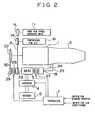
- FIG. 2is a diagram showing a second embodiment of the present invention.
- the second embodimentis different from the first embodiment shown in FIG. 1 in that a pulley 29 and the pulley 23 are disposed coaxially; an electromagnetic clutch 28 for enabling/disabling power transmission between the engine 1 and the M/G 3 is disposed between the pulley 23 and the pulley 29; and a belt 30 is set between the pulley 22 disposed above the engine 1 and the pulley 29.
- the auxiliary machinesare operated at the economy running mode while the engine is stopped similarly to those according to the first embodiment.
- the electromagnetic clutch 28is disposed adjacent to the M/G 3 as described above. Therefore the torque to be transmitted by the electromagnetic clutch 28 can be reduced because the pulley 22 does not have to be operated. Therefore, the size, weight and the cost of the electromagnetic clutch 28 can be reduced. Since the pulley 22 does not have to be operated, electric power required for the M/G 3 can be reduced.
- FIGS. 3 and 4are diagrams showing third and fourth embodiments of the present invention respectively.
- FIG. 3shows a structure in which reduction mechanisms 33, 34, 35, a brake 31 and a clutch 32 are disposed between the M/G 3 and the pulley 23 as shown in FIG. 1 .
- FIG. 4shows a structure in which the reduction mechanisms 33, 34, 35, the brake 31 and the clutch 32 are disposed between the M/G 3 and the pulley 23 as shown in FIG. 2 .
- reference numeral 33represents a sun gear
- 34represents a carrier
- 35represents a ring gear.
- the rotational force of the M/G 3is transmitted at a decreased speed from the sun gear 33 to the carrier 34.
- the force required to crank the engine 1can be maintained. Therefore, electric power required for the M/G 3 can be reduced.
- the brake 31is turned OFF and the clutch 32 is turned ON.
- the electromagnetic clutch 27is brought to an engaged state and the electromagnetic clutch 26 (identical to the electromagnetic clutch 28 in the structure shown in FIG. 4 ) is brought to a disengaged state.
- the M/G 3 and the pulley 23are directly connected with each other so that the number of revolutions required to operate the auxiliary machines 11, 16 can be obtained.
- the brake 31is turned OFF and the clutch 32 is brought to an engaged state.
- the electromagnetic clutch 27is brought to a disengaged state and the electromagnetic clutch 26 (identical to the electromagnetic clutch 28 in the structure shown in FIG. 4 ) is brought to the engaged state.
- the M/G 3 and the pulley 23are directly connected with each other so that the rotations of the pulley 23 are transmitted to the M/G 3 while maintaining the rotational speed of the pulley 23.
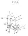
- FIGS. 5 , 6 , 7 and 8are diagrams showing a fifth embodiment of the present invention.
- FIG. 5shows the system of the fifth embodiment.
- FIG. 6is a cross sectional view showing the detailed structures of the motor generator 3 and a reduction gear 15.
- FIG. 7is a schematic view showing the detailed structure of a planetary gear mechanism when the reduction gear 15 is viewed from the axial direction.
- FIG. 8is a schematic view showing the system of the fifth embodiment.
- an engine 1 and an automatic transmission 2(hereinafter referred to as an "A/T") disposed adjacent to the engine 1.
- a motor generator 3(hereinafter referred to as an "M/G”) serves as a motor and an electric generator.
- a crank shaft 17 as a drive shaft for the engine 1 and the rotational shaft of the M/G 3are disposed in parallel with and apart from each other.
- a reduction gear 15is disposed between the M/G 3 and the crank shaft 17 so that rotation of the rotational shaft of the M/G 3 is reduced and transmitted to the crank shaft 17.
- a crank-side sprocket 12(a rotative member) is connected and secured to the crank shaft 17.
- An M/G-side sprocket 13is connected and secured to a rotative element of the reduction gear 15.
- a chain 18is set between the crank-side sprocket 12 and the M/G-side sprocket 13.
- FIG. 5shows a pump 11 for a power steering unit and a compressor 16 for an air conditioner, each of which is an auxiliary machine.
- a pulley 10is directly connected to the rotational shaft of the M/G 3.
- Pulleys 9 and 14are secured to the respective ends of the rotational shafts of the pump 11 for a power steering unit and the compressor 16 for the air conditioner.
- a belt 8is set among the pulleys 9, 10 and 14.
- the structureseems to show that the M/G-side sprocket 13 and the pulley 10 are coaxially and integrally connected to the rotational shaft of the M/G 3.
- the M/G-side sprocket 13 and the pulley 10are not always rotated at the same speed as described later.
- the transmission of the rotational forceis performed independently.
- An inverter 4is electrically connected to the M/G 3 and arranged to vary the amount of electric energy to be supplied from a battery 5 as a power source to the M/G 3 so as to control the number of revolutions of the M/G 3.
- the inverter 4also performs control to store electric energy generated by the M/G 3 in the battery 5.
- the M/G 3is connected to an oil pump 19 for the A/T 2 through an electromagnetic clutch 27.
- An oil inlet pipe 24is connected to the oil pump 19.
- An oil outlet pipe 25is connected to the oil pump 19.
- a controller 7transmits, to the inverter 4, a signal for controlling the switching operation, ON-OFF control signals to the electromagnetic clutch 27 and ON-OFF control signals to the electromagnetic coil of the reduction gear 15 to be described later.
- the controller 7receives a signal indicating the number of revolutions of the M/G 3, a signal for switching the economy running mode, a signal for switching the operation of the air conditioner, an engine status signal indicating, for example, the number of revolutions of the engine 1, a vehicle status signal (not shown) indicating the vehicle speed and the like and a status signal (not shown) of the A/T 2 indicating the range selected by the shift lever.
- the controller 7performs an operation for reading data from a memory and a calculating operation. Then, the controller 7 transmits arbitrary control signals to the reduction gear 15, the inverter 4, the electromagnetic clutch 27 and the like.
- the controller 7may be formed as a so-called computer system provided with known units including a CPU, a RAM, a ROM, a bi-directional communication bus, interface circuits (a signal conversion circuit and the like) and an auxiliary memory.
- One end of a casing 36 of the M/G 3is secured to a bracket 38 of a cylinder block 37 of the engine 1 with bolts 40 such that a rotational shaft 39 is in parallel with the crank shaft 17 and the sprocket 13 secured to the rotative element of the reduction gear 15 is flush with the crank-side sprocket 12 secured to the crank shaft 17.
- the other end of the casing 36is secured to extended first and second covers 64, 58 to be described later.
- the M/G 3is secured to a portion opposite to the A/T 2 of the engine 1 and adjacent to a sprocket 82 for operating a cam shaft 81 in the engine 1 secured to the crank shaft 17.
- a stator 41is disposed in the casing 36 to surround a rotor 42.
- the rotor 42is rotatively disposed opposite to the stator 41.
- the rotational shaft 39is secured integrally with the rotor 42 for integral rotation.
- a radial bearing 43is provided for rotatively supporting the rotational shaft 39.
- the reduction gear 15 connected to the rotational shaft 39will now be described with reference to FIGS. 6 and 7 .
- the reduction gear 15has a planetary gear unit including a sun gear 45, a pinion gears 46, a ring gear 47 and a carrier 55 therein.
- the sun gear 45 of the planetary gear unitis formed integrally with the rotational shaft 39.
- Three pinion gears 46are disposed on outer periphery of the rotational shaft 39 at the same intervals of an angular degree of 120° and engaged with the sun gear 45. The relative positions among the three pinion gears 46 are kept unchanged.
- the three pinion gears 46are able to turn around and move around the sun gear 45.
- each of the pinion gears 46is rotatively disposed in the ring gear 47 such that the inner periphery of the ring gear 47 is engaged with the pinion gear 46.
- a plate 48 spline-engaged to prevent relative rotation with respect to the ring gear 47is disposed on the outer periphery of the ring gear 47.
- An electromagnetic clutch 49is disposed opposite to the plate 48.
- the electromagnetic clutch 49includes a coil 50 therein. When energizing the coil 50, the electromagnetic clutch 49 attracts the plate 48 by electromagnetic force. As a result, rotation of the ring gear 47 is inhibited.
- a one-way clutch 51is disposed between a portion of the rotational shaft 39 closer to the rotor 42 than the sun gear 45 and the ring gear 47.
- the one-way clutch 51allows the ring gear to rotate.
- the rotation of the ring gear 47can be transmitted to the rotational shaft 39.
- the rotation of the rotational shaft 39cannot be transmitted to the ring gear 47. It is controlled such that the speed of the rotational shaft 39 does not exceed the rotational speed of the ring gear 47 that has been enabled to rotate.
- the inside portion of the casing 36is sectioned into two spaces by a partition 52.
- the stator 41 and the rotor 42are accommodated in one of the spaces, while the planetary gear unit, the one-way clutch 51, the electromagnetic clutch 49 and the plate 48 are accommodated in another space.
- the coil 50 of the electromagnetic clutch 49is secured to the partition 52.
- a signal for energizing the coil 50is transmitted from the controller 7.
- a sealing member 53is provided.
- a carrier 55is allowed to pass through each of the pinion gears 46 of the planetary gear unit through a needle bearing 54. Each carrier 55 is rotatively provided in the pinion gear 46.
- the carrier 55is connected to a hollow rotative member 70 and movable around the sun gear 45 and able to rotate about the sun gear 45 integrally therewith such that the relative positions of the carriers 55 are maintained.
- the hollow rotative member 70extends in the axial direction (to the left in the drawing) of the rotational shaft 39 and has a spline formed on the outer periphery for engagement with the M/G-side sprocket 13. The movement of the M/G-side sprocket 13 in the axial direction of the hollow rotative member 70 is restricted by a nut 56.
- the M/G-side sprocket 13is connected to the crank-side sprocket 12 of the engine 1 through the chain 18. Thus, rotation between the crank shaft 17 and the rotational shaft 39 of the M/G 3 can be transmitted.
- a bearing 60is provided for rotatively supporting the hollow rotative member 70.
- a sprocket (a rotative member) 82 for operating the cam shaft 81 (see FIG. 8 ) of the engine 1is secured to the crank shaft 17 at a position closer to the body of the engine 1 than the crank-side sprocket 12.
- the cam shaft 81is disposed in parallel with the crank shaft 17.
- a cam-shaft sprocket 80is secured to the cam shaft 81 to correspond to the sprocket 82 for operating the cam shaft 81.
- a chain 85is provided between the sprocket 82 for operating the cam shaft 81 and the cam-shaft sprocket 80.
- the sprocket 82 for operating the cam shaft 81, the cam-shaft sprocket 80 and the chain 85are disposed in a first space 63 defined by a cylinder block 37 and a first cover 64.
- Engine lubricating oilis supplied to the first space 63 so as to be circulated in the first space 63.
- the crank-side sprocket 12 for transmitting power between the M/G 3 and crank shaft 17is secured to the crank shaft 17 at a portion outside of the sprocket 82 for operating the cam shaft 81 coaxially therewith.
- a second space 59 defined by the first cover 64 and the second cover 58 attached to the outside of the first cover 64accommodates the crank-side sprocket 12, the M/G-side sprocket 13 and the chain 18.
- the first space 63 and the second space 59communicate with each other so that lubricating oil supplied from the engine 1 is sufficiently supplied into the second space 59.
- the first cover 64 and the second cover 58extend toward the M/G 3.
- Three portions (only one portion is illustrated) of a cover 68are secured to the first cover 64 with bolts 65. Another portion of the cover 68 is secured to the first and second covers 64 and 58 with a bolt 67.
- Lubricating oil circulated to the first space 63 and the second space 59is supplied through a pipe (not shown) and dropping for lubricating required portions.
- Lubricating oilis supplied to the planetary gear unit through a pipe (not shown) for lubricating each portion of the planetary gear unit, and then allowed to pass through the inside portion of the hollow rotative member 70. Then the lubricating oil is returned from the second space 59 to an oil pan (not shown) where it is mixed with oil which has been dropped after lubricating the other portions of the engine.
- the rotational shaft 39penetrates the hollow rotative member 70 and the second cover 58 to project to the outside portion.
- the pulley 10 for driving the auxiliary machinesis secured to the rotational shaft 39 by spline engagement, such that the rotational shaft 39 and the pulley 10 can be integrally rotated.
- a sealing member 61is disposed between the second cover 56 and the pulley 10.
- FIG. 7is a schematic cross sectional view showing the planetary gear unit when it is viewed from the axial direction of the rotational shaft 39.
- the relative positions of the sun gear 45, the pinion gears 46, the ring gear 47 and the carrier 55can easily be understood from FIG. 7 .
- the pulley 10 rotated integrally with the rotational shaft 39drives the auxiliary machines 11, 16.
- the one-way clutch 51prevents transmission of the rotation of the rotational shaft 39 to the ring gear 47. Since the carrier 55 is stopped by a sliding resistance of the engine 1 while the ring gear 47 is allowed to rotate, the pinion gears 46 only turn around without moving around the sun gear which is turning around. (the ring gear 47 inversely rotates around the sun gear 45 as the pinion gears 46 rotate). Thus, only the auxiliary machines are operated by the M/G 3. Therefore, the auxiliary machines can be operated with small electric power without operating the engine 1.
- the controller 7transmits an ON signal to the electromagnetic clutch 49 of the reduction gear 15 to prevent the rotation of the ring gear 47.
- the rotational shaft 39 of the M/G 3is rotated in the foregoing state, the rotation of the sun gear 45 is transmitted to the pinion gears 46. Since the rotation of the ring gear 47 is prevented, the pinion gears 46 move around the sun gear 45 while turning around by themselves.
- the carrier 55 in each pinion gear 46moves around the sun gear 45 so that the hollow rotative member 70 and the M/G-side sprocket 13 are rotated coaxially with the rotational shaft 39.
- the rotational speed of the M/G-side sprocket 13is obtained by reducing the rotational speed of the rotational shaft 39 at a reduction ratio which is determined by the number of teeth of the sun gear 45 and that of the pinion gears 46. Therefore a sufficiently high torque for actuation is transmitted from the M/G 3 to the engine 1 because of the reduced speed of the sprockets 12, 13. Thus, the engine 1 is re-started. This leads to an effect of reducing the size of the M/G 3.
- the auxiliary machines 11, 16are operated by the M/G 3 in synchronization with rotation of the rotational shaft 39.
- the rotation of the crank shaft 17is transmitted to the M/G-side sprocket 13.
- the controller 7transmits an OFF signal to the electromagnetic clutch 49 so that the ring gear 47 is brought to a rotative state.
- the rotational shaft 39is caused to be stopped by a load generated in conjunction with electric power generation, the rotation of the carrier 55 causes the pinion gears 46 to turn and move around.
- ring gear 47is rotated at an accelerated speed.
- the one-way clutch 51transmits the rotation of the ring gear 47 to the rotational shaft 39.
- this embodimentis structured such that the portions corresponding to the clutches 26, 28 are contained in the reduction gear 15, the whole size can be reduced by eliminating these clutches 26, 28 as compared with the third embodiment.
- This embodimenthas the structure in which the second space 59 (a space projecting over the body of the engine 1) for accommodating the power transmission means (the chain 18) between the M/G 3 and the engine 1 is defined by the cylinder block 37, the first cover 64 and the second cover 58.
- the shape of the cylinder block 37thus, is not required to be changed, resulting in cost reduction.
- the lubricating oil for the engine 1can be used for circulation. Since the crank shaft 17 and the M/G 3 are connected with each other by the chain 18, excellent effect can be obtained in that power transmission can reliably be performed and noise generated during the operation can be reduced.
- each of the first to fourth embodimentshave the structure in which the power of the engine and that of the motor can be transmitted through the chain and the sprocket
- another methodmay be employed.
- connection using pulleys and belts, connection using gears and another connection methodmay be employed.
- the compressor for the air conditionerdoes not have to be operated by the engine 1 at an idle state of the engine (revolutions in a poor fuel economy region) while the vehicle is stopped.
- the compressor 16 for air conditioneris rotated by the M/G 3 at the economy running mode while the engine 1 is stopped.
- the electric energy obtained from the battery 5is recovered by operating the M/G 3 as an electric generator in a revolution region of the engine 1 where an excellent fuel efficiency can be realized during operation of the engine 1.
- the fuel efficiency of the vehiclecan be further improved.
- each of the first to fourth embodimentshas the structure in which the engine 1 is not operated by the M/G 3 while the engine 1 is stopped, electric power required for the M/G 3 can be reduced. Thus, reduction in power consumption of the battery 5 can be realized.
Landscapes
- Engineering & Computer Science (AREA)
- Mechanical Engineering (AREA)
- Combustion & Propulsion (AREA)
- Chemical & Material Sciences (AREA)
- Transportation (AREA)
- General Engineering & Computer Science (AREA)
- Thermal Sciences (AREA)
- Physics & Mathematics (AREA)
- Power Engineering (AREA)
- Automation & Control Theory (AREA)
- Control Of Vehicle Engines Or Engines For Specific Uses (AREA)
- Hybrid Electric Vehicles (AREA)
- Auxiliary Drives, Propulsion Controls, And Safety Devices (AREA)
- Electric Propulsion And Braking For Vehicles (AREA)
Description
- The present invention relates to a power train system for a vehicle incorporating an engine and a motor. The invention also relates to a method for controlling a power train system.
- In recent years, an automatic engine stopping and starting apparatus (hereinafter referred to as an "economy running system") has been known for stopping an engine after a running vehicle has been stopped and restarting the engine if conditions for driving the vehicle have been satisfied again. Japanese Patent Laid-Open No.
9-39613 - The above-mentioned structure eliminates the need of electric motors to operate the auxiliary machines, such as the compressor for the air conditioner and the pump for the power steering unit. Thus, the space required for the structure of the economy running system can be minimized.
- However, the above-mentioned art to operate the auxiliary machines by maintaining revolution of the engine at the idle speed cannot reduce power consumption of the motor generator for operating the engine. Since the motor generator is, in general, operated by electric power of a battery mounted on the vehicle, power consumption of the battery is increased due to frequent stop operations of the vehicle. As a result, a battery having a large storage capacity must be mounted on the vehicle.
- A power train system is disclosed in European patent application No.
EP 0 645 271 A2 . In this disclosure, the electric motor/generator drives the accessories when the internal combustion engine is idling or off, thus allowing those accessories to be smaller while delivering adequate output. JP 08 197 962 A - Toyota's
EP 0 743 209 A2 shows a power output apparatus for a hybrid vehicle. EP 0 492 152 A1 shows a hybrid drive system according to the preamble of claim 1.- This summary of the invention does not necessarily describe all necessary features so that the invention may also reside in a sub-combination of these described features.
- In view of the foregoing, an object of the present invention is to operate a motor with smaller electric power when a vehicle is stopped.
- The above object is solved by combination of features of the independent claim, the dependent claims disclose further advantageous embodiments of the invention.
- According to the present invention, the power train system may include first and second rotative members having rotational shafts disposed in parallel with the drive shaft of the engine, a first cover joined to the engine to form a first space in association with the engine for accommodating the first rotative member, a second cover joined to an outside of the first cover to form a second space in association with the first cover for accommodating the second rotative member, a motor rotative member provided for the rotational shaft of the motor so as to be rotated in conjunction therewith, and a power transmission that connects the motor rotative member to either the first rotative member or the second rotative member such that power can be transmitted. The motor rotative member and the power transmission are accommodated in either the first space or the second space. As a result of the above-mentioned structure, the rotative member of the motor and the first and second rotative members provided for the drive shaft of the engine are connected with each other by the power transmission. The rotative members and the power transmission are accommodated in a space defined by the body of the engine and the first cover or the second cover joined to the body of the engine. Therefore, the motor can be mounted without considerably changing the structure of a conventional engine. The foregoing structure may be arranged such that the first and second spaces are allowed to communicate with each other and formed into spaces isolated from the outside portion of the engine, and lubricant may be supplied into the first and second spaces. The lubricant may be the one used to lubricate the engine and allowed to circulate to and from the engine.
- These and other aspects will be described in or apparent from the following detailed description of preferred embodiments.
- Preferred embodiments of the present invention will be described in detail with reference to the following drawings where like reference numbers indicate like parts, in which:
FIG. 1 is a diagram showing a system of a power train system according to a first embodiment of the present invention;FIG. 2 is a diagram showing a system of a power train system according to a second embodiment of the present invention;FIG. 3 is a diagram showing a system of a power train system according to a third embodiment of the present invention;FIG. 4 is a diagram showing a system of a power train system according to a fourth embodiment of the present invention;FIG. 5 is a diagram showing a system of a power train system according to a fifth embodiment of the present invention;FIG. 6 is a diagram showing detailed structures of a motor generator, a reducing gear and a mounting structure according to the fifth embodiment of the present invention;FIG. 7 is a schematic view showing a planetary gear unit according to the fifth embodiment of the present invention; andFIG. 8 is a schematic view showing the system of the fifth embodiment of the present invention.- Embodiments of the present invention will now be described with reference to the drawings.
FIG. 1 is a diagram showing the system of a power train system according to a first embodiment of the present invention. - Referring to
FIG. 1 , an engine 1 is mounted on a vehicle including an automatic transmission 2 (hereinafter referred to as an "A/T"), and a motor generator 3 (hereinafter referred to as an "M/G") serves as a motor and a power generator. The M/G 3 is connected to a crank shaft of the engine 1 through apulley 23, abelt 8 and apulley 22. An electromagnetic clutch 26 for enabling or disabling electric power supply is disposed between thepulley 23 and the crank shaft of the engine 1. The M/G 3 is connected to anoil pump 19 for the A/T 2 through anelectromagnetic clutch 27. Anoil inlet pipe 24 is connected to theoil pump 19. Anoil outlet pipe 25 is provided for theoil pump 19.Auxiliary machines auxiliary machines G 3 throughpulleys 9 and 14 and thebelt 8, respectively. Other auxiliary machines, such as an oil pump and a water pump for the engine 1 (not shown) are connected to the crank shaft and the M/G 3. Aninverter 4 is electrically connected to the M/G 3. Theinverter 4 performs a switching operation to vary the amount of electric energy which is supplied from abattery 5 serving as a power source to the M/G 3 so as to control the number of revolutions of the M/G 3. Moreover, theinverter 4 performs a switching operation to charge electric energy supplied from the M/G 3 to thebattery 5. Acontroller 7 controls engagement/disengagement of theelectromagnetic clutches 26, 27 and the switching operation of theinverter 4. Thecontroller 7 receives input signals, such as a signal indicating the number of revolutions of the M/G 3, a switching signal for selecting the economy running mode and a switching signal for operating the air conditioner. Note that lines shown inFIG. 1 and each having an arrow indicate signal lines. - The operation of the first embodiment will now be described. Initially, the M/G 3 is operated to start the engine 1. After starting the engine 1, the M/
G 3 acts as a power generator for storing electric energy in thebattery 5. It is preferable to perform the operation for charging electric energy at braking of a vehicle. When the engine is started, thecontroller 7 detects the number of revolutions of the M/G 3. Moreover, thecontroller 7 causes theinverter 4 to perform a switching operation such that a torque and the number of revolutions required to start the engine 1 are realized. If a signal for switching the air conditioner has been turned ON at starting of the engine, a higher torque is required compared with the OFF state of the air conditioner. Therefore, thecontroller 7 applies, to theinverter 4, a switching control signal to allow the M/G 3 to rotate at a higher torque with a large number of revolutions. The switching control signal to be output may be determined such that a variety of status signals of the engine 1, the A/T 2 and the vehicle are extracted to thecontroller 7 so as to be collated with a map memory stored therein. Alternatively, the switching control signal may be determined by calculations performed by a calculating unit disposed in thecontroller 7. When the engine is started, theelectromagnetic clutches 26, 27 are connected. - When an economy-running-mode signal is turned ON while the vehicle is stopped, the
controller 7 stops the engine 1 by transmitting a signal for interrupting fuel supply to the engine 1. Note that a line for transmitting the signal for interrupting the fuel supply is omitted fromFIG. 1 . The economy-running-mode signal is applied to thecontroller 7, for example, by a driver who depresses a switch disposed in the inside of the vehicle. The economy running operation can be performed at the economy running mode under condition where, for example, the vehicle speed is zero and the shift lever is in the range D or range N. In the foregoing state, thecontroller 7 transmits, to the electromagnetic clutch 26, a control signal for disconnection. Thus, no power is transmitted between thepulley 22 and the engine 1. On the other hand, theelectromagnetic clutch 27 is brought to a connected state to allow the M/G 3 to operate theoil pump 19. This is because the starting clutch (not shown) disposed in the A/T 2 is arranged to be immediately engaged for driving the vehicle smoothly upon re-starting of the engine. - In the case where the air conditioner and the power steering are required to be operated even if the engine 1 is stopped, the
controller 7 applies, to theinverter 4, a switching control signal to rotate the M/G 3 at the number of revolutions and the torque corresponding to the loads of thepump 11 for a power steering unit, thecompressor 16 for the air conditioner and theoil pump 19 for the A/T 2. When the engine 1 is re-started from a state where the vehicle is stopped, theelectromagnetic clutches 26, 27 are connected to rotate the M/G 3 at arbitrary number of revolutions and torque. - As described above, the power train system according to the first embodiment has the structure to stop the engine 1 while the vehicle is stopped and to cause the M/
G 3 to operate thepump 11 for a power steering unit and thecompressor 16 for the air conditioner. Thus, the power of the M/G 3 is not transmitted to the engine 1. The power consumption can be reduced compared with a structure in which the M/G keeps the engine at the idle speed for operating the compressor for the air conditioner and the pump for the power steering. Since the M/G 3 also serves as the means for operating thepump 11 for a power steering unit and thecompressor 16 for the air conditioner, the system can be simplified. FIG. 2 is a diagram showing a second embodiment of the present invention. The second embodiment is different from the first embodiment shown inFIG. 1 in that apulley 29 and thepulley 23 are disposed coaxially; anelectromagnetic clutch 28 for enabling/disabling power transmission between the engine 1 and the M/G 3 is disposed between thepulley 23 and thepulley 29; and abelt 30 is set between thepulley 22 disposed above the engine 1 and thepulley 29.- The auxiliary machines are operated at the economy running mode while the engine is stopped similarly to those according to the first embodiment. Unlike the first embodiment, the
electromagnetic clutch 28 is disposed adjacent to the M/G 3 as described above. Therefore the torque to be transmitted by the electromagnetic clutch 28 can be reduced because thepulley 22 does not have to be operated. Therefore, the size, weight and the cost of the electromagnetic clutch 28 can be reduced. Since thepulley 22 does not have to be operated, electric power required for the M/G 3 can be reduced. FIGS. 3 and4 are diagrams showing third and fourth embodiments of the present invention respectively.FIG. 3 shows a structure in whichreduction mechanisms brake 31 and a clutch 32 are disposed between the M/G 3 and thepulley 23 as shown inFIG. 1 .FIG. 4 shows a structure in which thereduction mechanisms brake 31 and the clutch 32 are disposed between the M/G 3 and thepulley 23 as shown inFIG. 2 . Note thatreference numeral 33 represents a sun gear, 34 represents a carrier and 35 represents a ring gear. When the M/G 3 cranks (actuates) the engine 1, thebrake 31 is turned ON and the clutch 32 is turned OFF. Thus, the rotational force of the M/G 3 is transmitted at a decreased speed from thesun gear 33 to thecarrier 34. As a result, even if the size of each of the M/G 3 and theinverter 4 is reduced, the force required to crank the engine 1 can be maintained. Therefore, electric power required for the M/G 3 can be reduced.- When the
pump 11 for a power steering unit and thecompressor 16 for the air conditioner as the auxiliary machines are operated by the M/G 3 while the engine 1 is stopped, thebrake 31 is turned OFF and the clutch 32 is turned ON. At this time, theelectromagnetic clutch 27 is brought to an engaged state and the electromagnetic clutch 26 (identical to the electromagnetic clutch 28 in the structure shown inFIG. 4 ) is brought to a disengaged state. Thus, the M/G 3 and thepulley 23 are directly connected with each other so that the number of revolutions required to operate theauxiliary machines - When the M/
G 3 is used as an electric generator or theauxiliary machines brake 31 is turned OFF and the clutch 32 is brought to an engaged state. At this time, theelectromagnetic clutch 27 is brought to a disengaged state and the electromagnetic clutch 26 (identical to the electromagnetic clutch 28 in the structure shown inFIG. 4 ) is brought to the engaged state. Thus, the M/G 3 and thepulley 23 are directly connected with each other so that the rotations of thepulley 23 are transmitted to the M/G 3 while maintaining the rotational speed of thepulley 23. FIGS. 5 ,6 ,7 and8 are diagrams showing a fifth embodiment of the present invention.FIG. 5 shows the system of the fifth embodiment.FIG. 6 is a cross sectional view showing the detailed structures of themotor generator 3 and areduction gear 15.FIG. 7 is a schematic view showing the detailed structure of a planetary gear mechanism when thereduction gear 15 is viewed from the axial direction.FIG. 8 is a schematic view showing the system of the fifth embodiment.- Referring to
FIG. 5 , there is provided an engine 1 and an automatic transmission 2 (hereinafter referred to as an "A/T") disposed adjacent to the engine 1. A motor generator 3 (hereinafter referred to as an "M/G") serves as a motor and an electric generator. Acrank shaft 17 as a drive shaft for the engine 1 and the rotational shaft of the M/G 3 are disposed in parallel with and apart from each other. Areduction gear 15 is disposed between the M/G 3 and thecrank shaft 17 so that rotation of the rotational shaft of the M/G 3 is reduced and transmitted to thecrank shaft 17. A crank-side sprocket 12 (a rotative member) is connected and secured to thecrank shaft 17. An M/G-side sprocket 13 is connected and secured to a rotative element of thereduction gear 15. Achain 18 is set between the crank-side sprocket 12 and the M/G-side sprocket 13. FIG. 5 shows apump 11 for a power steering unit and acompressor 16 for an air conditioner, each of which is an auxiliary machine. Apulley 10 is directly connected to the rotational shaft of the M/G 3.Pulleys 9 and 14 are secured to the respective ends of the rotational shafts of thepump 11 for a power steering unit and thecompressor 16 for the air conditioner. Abelt 8 is set among thepulleys pulleys belt 8, for example, constitute a power transmission means for transmitting rotation of the M/G 3 to theauxiliary machines FIG. 5 , the structure seems to show that the M/G-side sprocket 13 and thepulley 10 are coaxially and integrally connected to the rotational shaft of the M/G 3. However, the M/G-side sprocket 13 and thepulley 10 are not always rotated at the same speed as described later. The transmission of the rotational force is performed independently.- An
inverter 4 is electrically connected to the M/G 3 and arranged to vary the amount of electric energy to be supplied from abattery 5 as a power source to the M/G 3 so as to control the number of revolutions of the M/G 3. Theinverter 4 also performs control to store electric energy generated by the M/G 3 in thebattery 5. - The M/
G 3 is connected to anoil pump 19 for the A/T 2 through anelectromagnetic clutch 27. Anoil inlet pipe 24 is connected to theoil pump 19. Anoil outlet pipe 25 is connected to theoil pump 19. The foregoing structure enables the M/G 3 to operate theoil pump 19 by bringing the electromagnetic clutch 27 to an engaged state while the engine is stopped at the economy running mode. This is because the starting clutch (not shown) disposed in the A/T 2 is arranged to be immediately engaged for driving the vehicle smoothly upon re-start of the engine. - Referring to
FIG. 5 , acontroller 7 transmits, to theinverter 4, a signal for controlling the switching operation, ON-OFF control signals to theelectromagnetic clutch 27 and ON-OFF control signals to the electromagnetic coil of thereduction gear 15 to be described later. Thecontroller 7 receives a signal indicating the number of revolutions of the M/G 3, a signal for switching the economy running mode, a signal for switching the operation of the air conditioner, an engine status signal indicating, for example, the number of revolutions of the engine 1, a vehicle status signal (not shown) indicating the vehicle speed and the like and a status signal (not shown) of the A/T 2 indicating the range selected by the shift lever. In accordance with information indicated by the above-mentioned supplied signals, thecontroller 7 performs an operation for reading data from a memory and a calculating operation. Then, thecontroller 7 transmits arbitrary control signals to thereduction gear 15, theinverter 4, theelectromagnetic clutch 27 and the like. Thecontroller 7 may be formed as a so-called computer system provided with known units including a CPU, a RAM, a ROM, a bi-directional communication bus, interface circuits (a signal conversion circuit and the like) and an auxiliary memory. - The detailed structures of the M/
G 3, thereduction gear 15 and a structure for mounting the M/G 3 on the engine 1 will now be described with reference toFIG. 6 . One end of acasing 36 of the M/G 3 is secured to abracket 38 of acylinder block 37 of the engine 1 withbolts 40 such that arotational shaft 39 is in parallel with thecrank shaft 17 and thesprocket 13 secured to the rotative element of thereduction gear 15 is flush with the crank-side sprocket 12 secured to thecrank shaft 17. The other end of thecasing 36 is secured to extended first and second covers 64, 58 to be described later. In this embodiment, the M/G 3 is secured to a portion opposite to the A/T 2 of the engine 1 and adjacent to asprocket 82 for operating acam shaft 81 in the engine 1 secured to thecrank shaft 17. Astator 41 is disposed in thecasing 36 to surround arotor 42. Therotor 42 is rotatively disposed opposite to thestator 41. Therotational shaft 39 is secured integrally with therotor 42 for integral rotation. Aradial bearing 43 is provided for rotatively supporting therotational shaft 39. - The
reduction gear 15 connected to therotational shaft 39 will now be described with reference toFIGS. 6 and7 . Thereduction gear 15 has a planetary gear unit including asun gear 45, a pinion gears 46, aring gear 47 and acarrier 55 therein. Thesun gear 45 of the planetary gear unit is formed integrally with therotational shaft 39. Three pinion gears 46 are disposed on outer periphery of therotational shaft 39 at the same intervals of an angular degree of 120° and engaged with thesun gear 45. The relative positions among the three pinion gears 46 are kept unchanged. The three pinion gears 46 are able to turn around and move around thesun gear 45. Moreover, each of the pinion gears 46 is rotatively disposed in thering gear 47 such that the inner periphery of thering gear 47 is engaged with thepinion gear 46. Aplate 48 spline-engaged to prevent relative rotation with respect to thering gear 47 is disposed on the outer periphery of thering gear 47. An electromagnetic clutch 49 is disposed opposite to theplate 48. Theelectromagnetic clutch 49 includes acoil 50 therein. When energizing thecoil 50, theelectromagnetic clutch 49 attracts theplate 48 by electromagnetic force. As a result, rotation of thering gear 47 is inhibited. A one-way clutch 51 is disposed between a portion of therotational shaft 39 closer to therotor 42 than thesun gear 45 and thering gear 47. The one-way clutch 51 allows the ring gear to rotate. The rotation of thering gear 47 can be transmitted to therotational shaft 39. On the other hand, the rotation of therotational shaft 39 cannot be transmitted to thering gear 47. It is controlled such that the speed of therotational shaft 39 does not exceed the rotational speed of thering gear 47 that has been enabled to rotate. - The inside portion of the
casing 36 is sectioned into two spaces by apartition 52. Thestator 41 and therotor 42 are accommodated in one of the spaces, while the planetary gear unit, the one-way clutch 51, theelectromagnetic clutch 49 and theplate 48 are accommodated in another space. Thecoil 50 of theelectromagnetic clutch 49 is secured to thepartition 52. A signal for energizing thecoil 50 is transmitted from thecontroller 7. As shown inFIG. 6 , a sealingmember 53 is provided. - A
carrier 55 is allowed to pass through each of the pinion gears 46 of the planetary gear unit through aneedle bearing 54. Eachcarrier 55 is rotatively provided in thepinion gear 46. Thecarrier 55 is connected to ahollow rotative member 70 and movable around thesun gear 45 and able to rotate about thesun gear 45 integrally therewith such that the relative positions of thecarriers 55 are maintained. Thehollow rotative member 70 extends in the axial direction (to the left in the drawing) of therotational shaft 39 and has a spline formed on the outer periphery for engagement with the M/G-side sprocket 13. The movement of the M/G-side sprocket 13 in the axial direction of thehollow rotative member 70 is restricted by anut 56. The M/G-side sprocket 13 is connected to the crank-side sprocket 12 of the engine 1 through thechain 18. Thus, rotation between thecrank shaft 17 and therotational shaft 39 of the M/G 3 can be transmitted. Abearing 60 is provided for rotatively supporting thehollow rotative member 70. - As shown in
FIGS. 6 and8 , a sprocket (a rotative member) 82 for operating the cam shaft 81 (seeFIG. 8 ) of the engine 1 is secured to thecrank shaft 17 at a position closer to the body of the engine 1 than the crank-side sprocket 12. Thecam shaft 81 is disposed in parallel with thecrank shaft 17. A cam-shaft sprocket 80 is secured to thecam shaft 81 to correspond to thesprocket 82 for operating thecam shaft 81. Achain 85 is provided between thesprocket 82 for operating thecam shaft 81 and the cam-shaft sprocket 80. Thus, rotations of thecrank shaft 17 are transmitted to thecam shaft 81. Thesprocket 82 for operating thecam shaft 81, the cam-shaft sprocket 80 and thechain 85 are disposed in afirst space 63 defined by acylinder block 37 and afirst cover 64. Engine lubricating oil is supplied to thefirst space 63 so as to be circulated in thefirst space 63. The crank-side sprocket 12 for transmitting power between the M/G 3 and crankshaft 17 is secured to thecrank shaft 17 at a portion outside of thesprocket 82 for operating thecam shaft 81 coaxially therewith. Asecond space 59 defined by thefirst cover 64 and thesecond cover 58 attached to the outside of thefirst cover 64 accommodates the crank-side sprocket 12, the M/G-side sprocket 13 and thechain 18. Thefirst space 63 and thesecond space 59 communicate with each other so that lubricating oil supplied from the engine 1 is sufficiently supplied into thesecond space 59. Thefirst cover 64 and thesecond cover 58 extend toward the M/G 3. Three portions (only one portion is illustrated) of acover 68 are secured to thefirst cover 64 withbolts 65. Another portion of thecover 68 is secured to the first and second covers 64 and 58 with abolt 67. Lubricating oil circulated to thefirst space 63 and thesecond space 59 is supplied through a pipe (not shown) and dropping for lubricating required portions. Lubricating oil is supplied to the planetary gear unit through a pipe (not shown) for lubricating each portion of the planetary gear unit, and then allowed to pass through the inside portion of thehollow rotative member 70. Then the lubricating oil is returned from thesecond space 59 to an oil pan (not shown) where it is mixed with oil which has been dropped after lubricating the other portions of the engine. - The
rotational shaft 39 penetrates thehollow rotative member 70 and thesecond cover 58 to project to the outside portion. Thepulley 10 for driving the auxiliary machines is secured to therotational shaft 39 by spline engagement, such that therotational shaft 39 and thepulley 10 can be integrally rotated. A sealing member 61 is disposed between thesecond cover 56 and thepulley 10. FIG. 7 is a schematic cross sectional view showing the planetary gear unit when it is viewed from the axial direction of therotational shaft 39. The relative positions of thesun gear 45, the pinion gears 46, thering gear 47 and thecarrier 55 can easily be understood fromFIG. 7 .- The operation of the fifth embodiment will now be described. When the economy running mode has been started by application of an ON signal for switching the economy running switch on, fuel supply to the engine 1 is interrupted if predetermined conditions are satisfied. Thus, the engine 1 is stopped. At this time, an ON signal is transmitted from the
controller 7 to the electromagnetic clutch 27 which is brought to an ON state. Since thepump 11 for a power steering unit and thecompressor 16 for air conditioner as the auxiliary machines are required to be operated while the engine 1 is stopped, electric energy of thebattery 5 is supplied to the M/G 3 for rotation. The rotation of the M/G 3 is controlled by thecontroller 7 and theinverter 4. At this time, thecontroller 7 transmits an OFF signal to the electromagnetic clutch 49 in thereduction gear 15 to allow thering gear 47 of the planetary gear unit to rotate. - When the
rotational shaft 39 of the M/G 3 is rotated as shown inFIG. 6 , thepulley 10 rotated integrally with therotational shaft 39 drives theauxiliary machines rotational shaft 39 to thering gear 47. Since thecarrier 55 is stopped by a sliding resistance of the engine 1 while thering gear 47 is allowed to rotate, the pinion gears 46 only turn around without moving around the sun gear which is turning around. (thering gear 47 inversely rotates around thesun gear 45 as the pinion gears 46 rotate). Thus, only the auxiliary machines are operated by the M/G 3. Therefore, the auxiliary machines can be operated with small electric power without operating the engine 1. - When the engine 1 is re-started at the economy running mode, the
controller 7 transmits an ON signal to theelectromagnetic clutch 49 of thereduction gear 15 to prevent the rotation of thering gear 47. When therotational shaft 39 of the M/G 3 is rotated in the foregoing state, the rotation of thesun gear 45 is transmitted to the pinion gears 46. Since the rotation of thering gear 47 is prevented, the pinion gears 46 move around thesun gear 45 while turning around by themselves. Thus, thecarrier 55 in eachpinion gear 46 moves around thesun gear 45 so that thehollow rotative member 70 and the M/G-side sprocket 13 are rotated coaxially with therotational shaft 39. At this time, the rotational speed of the M/G-side sprocket 13 is obtained by reducing the rotational speed of therotational shaft 39 at a reduction ratio which is determined by the number of teeth of thesun gear 45 and that of the pinion gears 46. Therefore a sufficiently high torque for actuation is transmitted from the M/G 3 to the engine 1 because of the reduced speed of thesprockets G 3. Theauxiliary machines G 3 in synchronization with rotation of therotational shaft 39. - When the power of the engine 1 or the kinetic energy of the vehicle is attempted to be recovered as electric energy while operating the engine or braking the vehicle, the rotation of the
crank shaft 17 is transmitted to the M/G-side sprocket 13. Thus, thecarrier 55 is rotated. At this time, thecontroller 7 transmits an OFF signal to the electromagnetic clutch 49 so that thering gear 47 is brought to a rotative state. Although therotational shaft 39 is caused to be stopped by a load generated in conjunction with electric power generation, the rotation of thecarrier 55 causes the pinion gears 46 to turn and move around. Thus,ring gear 47 is rotated at an accelerated speed. Then, the one-way clutch 51 transmits the rotation of thering gear 47 to therotational shaft 39. Since thecarrier 55 and thering gear 47 integrally rotate about thesun gear 45, the rotation of thecrank shaft 17 is transmitted to the M/G-side sprocket 13 and therotational shaft 39 at the same speed. At this time, therotational shaft 39 is rotated to cause theauxiliary machines G 3 to generate electric power simultaneously. - Since this embodiment is structured such that the portions corresponding to the
clutches 26, 28 are contained in thereduction gear 15, the whole size can be reduced by eliminating theseclutches 26, 28 as compared with the third embodiment. - This embodiment has the structure in which the second space 59 (a space projecting over the body of the engine 1) for accommodating the power transmission means (the chain 18) between the M/
G 3 and the engine 1 is defined by thecylinder block 37, thefirst cover 64 and thesecond cover 58. The shape of thecylinder block 37, thus, is not required to be changed, resulting in cost reduction. The lubricating oil for the engine 1 can be used for circulation. Since thecrank shaft 17 and the M/G 3 are connected with each other by thechain 18, excellent effect can be obtained in that power transmission can reliably be performed and noise generated during the operation can be reduced. - Although each of the first to fourth embodiments have the structure in which the power of the engine and that of the motor can be transmitted through the chain and the sprocket, another method may be employed. For example, connection using pulleys and belts, connection using gears and another connection method may be employed.
- In the first to fourth embodiments, if it is structured such that the air conditioner is operated by the M/
G 3 while the engine 1 is stopped, the compressor for the air conditioner does not have to be operated by the engine 1 at an idle state of the engine (revolutions in a poor fuel economy region) while the vehicle is stopped. Thecompressor 16 for air conditioner is rotated by the M/G 3 at the economy running mode while the engine 1 is stopped. The electric energy obtained from thebattery 5 is recovered by operating the M/G 3 as an electric generator in a revolution region of the engine 1 where an excellent fuel efficiency can be realized during operation of the engine 1. Thus, the fuel efficiency of the vehicle can be further improved. - Since each of the first to fourth embodiments has the structure in which the engine 1 is not operated by the M/
G 3 while the engine 1 is stopped, electric power required for the M/G 3 can be reduced. Thus, reduction in power consumption of thebattery 5 can be realized.
Claims (5)
- A power train system comprising:first and second rotative members (82, 12) having rotational shafts disposed in parallel with the drive shaft of an engine (1); a motor rotative member (13) provided for a rotational shaft of a motor (3) so as to be rotated in conjunction therewith;
characterized by comprisinga first cover (64) joined to said engine (1) to form a first space (63) in association with said engine (1) for accommodating said first rotative member (82);a second cover (58) joined to an outside of said first cover (64) to form a second space (59) in association with said first cover (64) for accommodating said second rotative member (12);power transmission means (18) for connecting said motor rotative member (13) to either said first rotative member (82) or said second rotative member (12) such that power can be transmitted; and whereinsaid motor rotative member (13) and said power transmission means (18) are accommodated in either said first space (63) or said second space (59). - A power train system according to claim 1, wherein said first and second spaces (63, 59) are communicated with each other and formed separately from the outside of the engine (1),
a lubricant is supplied into said first and second spaces (63, 59), and
enabled to circulate to and from the engine (1). - A power train system according to claim 1 or 2, wherein
the first rotative member is a sprocket (82) for operating the cam shaft of the engine,
the second rotative member is a crank-side sprocket (12),
the power transmission means is a chain (18),
the motor rotative member is a M/G-side sprocket (13) which is connected to the crank-side sprocket (12) via the chain (18),
the M/G-side sprocket (13) and the chain (18) are accommodated in the second space (59). - A power train system according to any one of claims 1 to 3, wherein
the power train system has an engine (1) and a motor (3) connected to a drive shaft of the engine (1),characterized by comprising:a transmission mechanism (15) disposed between said engine (1) and said motor (3) and capable of transmitting rotations of the rotational shaft of said motor (3) to the drive shaft of said engine (1) at a changed speed;an auxiliary machine (11, 16) connected to the rotational shaft of said motor (3) and operated by said engine (1) or said motor (3); and whereinsaid transmission mechanism (15) reduces the speed of rotations of the rotational shaft of said motor (1) and transmits the rotations to the drive shaft of said engine (1) when said auxiliary machine (11, 16) is operated by said motor (3) in a state where said engine (1) is stopped. - A power train system according to claim 4 , wherein
said transmission mechanism (15) interrupts transmission of rotations of the rotational shaft of said motor (3) to the drive shaft of said engine (1) when the auxiliary machine (11, 16) is operated by said motor (3) in a state where said engine (1) is stopped.
Applications Claiming Priority (5)
| Application Number | Priority Date | Filing Date | Title |
|---|---|---|---|
| JP31750797 | 1997-11-18 | ||
| JP31750797AJP3536627B2 (en) | 1997-11-18 | 1997-11-18 | Vehicle drive unit |
| JP6179598AJP3465576B2 (en) | 1998-03-12 | 1998-03-12 | Vehicle motor mounting structure |
| JP6179598 | 1998-03-12 | ||
| EP98117937AEP0916546B1 (en) | 1997-11-18 | 1998-09-22 | Engine accessories drive system for a vehicle and method for operating same |
Related Parent Applications (1)
| Application Number | Title | Priority Date | Filing Date |
|---|---|---|---|
| EP98117937.7Division | 1998-09-22 |
Publications (4)
| Publication Number | Publication Date |
|---|---|
| EP1586477A2 EP1586477A2 (en) | 2005-10-19 |
| EP1586477A3 EP1586477A3 (en) | 2011-09-14 |
| EP1586477B1true EP1586477B1 (en) | 2013-03-27 |
| EP1586477B8 EP1586477B8 (en) | 2013-05-29 |
Family
ID=26402875
Family Applications (2)
| Application Number | Title | Priority Date | Filing Date |
|---|---|---|---|
| EP98117937AExpired - LifetimeEP0916546B1 (en) | 1997-11-18 | 1998-09-22 | Engine accessories drive system for a vehicle and method for operating same |
| EP05011491.7AExpired - LifetimeEP1586477B8 (en) | 1997-11-18 | 1998-09-22 | Arrangement of motor-generator in a vehicle |
Family Applications Before (1)
| Application Number | Title | Priority Date | Filing Date |
|---|---|---|---|
| EP98117937AExpired - LifetimeEP0916546B1 (en) | 1997-11-18 | 1998-09-22 | Engine accessories drive system for a vehicle and method for operating same |
Country Status (4)
| Country | Link |
|---|---|
| US (1) | US6048288A (en) |
| EP (2) | EP0916546B1 (en) |
| CA (1) | CA2244028C (en) |
| DE (1) | DE69831049T2 (en) |
Families Citing this family (206)
| Publication number | Priority date | Publication date | Assignee | Title |
|---|---|---|---|---|
| US6146302A (en)* | 1997-12-26 | 2000-11-14 | Fuji Jukogyo Kabushiki Kaisha | Power transmitting system for a hybrid motor vehicle |
| JP3611731B2 (en)* | 1998-10-15 | 2005-01-19 | 日産ディーゼル工業株式会社 | Auxiliary drive device for vehicle |
| JP3456159B2 (en)* | 1999-01-29 | 2003-10-14 | 三菱自動車工業株式会社 | Hybrid car |
| US6878092B1 (en)* | 1999-02-01 | 2005-04-12 | Robert Bosch Gmbh | Drive arrangement for at least one secondary aggregate of a motor vehicle and method for operating the drive arrangement |
| DE19931963A1 (en)* | 1999-07-12 | 2001-01-18 | Audi Ag | Drive device |
| DE10036504B4 (en) | 1999-08-02 | 2011-05-19 | Schaeffler Technologies Gmbh & Co. Kg | powertrain |
| DE19939814A1 (en)* | 1999-08-21 | 2001-02-22 | Bayerische Motoren Werke Ag | Internal combustion engine for driving a motor vehicle |
| JP3547347B2 (en)* | 1999-09-20 | 2004-07-28 | 株式会社日立製作所 | Motor generator for vehicles |
| JP3553437B2 (en)* | 1999-10-19 | 2004-08-11 | ジヤトコ株式会社 | Electric torque converter |
| JP3391750B2 (en)* | 1999-10-28 | 2003-03-31 | 株式会社デンソー | Vehicle accessory drive |
| DE19961796C1 (en)* | 1999-12-22 | 2001-09-13 | Daimler Chrysler Ag | Method for operating a motor vehicle |
| IT1319883B1 (en)* | 2000-02-04 | 2003-11-12 | Fiat Ricerche | PROCEDURE AND CONTROL SYSTEM FOR THE PROPULSION OF A VEHICLE |
| JP4066589B2 (en) | 2000-03-06 | 2008-03-26 | トヨタ自動車株式会社 | Idling stop control device for internal combustion engine and vehicle equipped with the same |
| JP3711323B2 (en)* | 2000-04-14 | 2005-11-02 | 三菱電機株式会社 | AC rotating electric machine for vehicles |
| US6484831B1 (en)* | 2000-07-14 | 2002-11-26 | Ford Global Technologies, Inc. | Hybrid electric vehicle |
| US6360834B1 (en)* | 2000-07-14 | 2002-03-26 | Ford Global Tech., Inc. | Hybrid electric vehicle |
| JP3867521B2 (en) | 2000-09-05 | 2007-01-10 | トヨタ自動車株式会社 | Electric oil pump control device |
| JP2002120552A (en)* | 2000-10-17 | 2002-04-23 | Toyota Industries Corp | Power generating and moving system |
| DE10057798A1 (en)* | 2000-11-22 | 2002-05-23 | Daimler Chrysler Ag | Automotive drive |
| JP2002362141A (en)* | 2001-01-09 | 2002-12-18 | Toyota Industries Corp | Air conditioner for vehicle |
| US6599214B2 (en) | 2001-02-09 | 2003-07-29 | Visteon Global Technologies, Inc. | Approach to integrating a starter-generator with an automatic transmission |
| US6598496B2 (en)* | 2001-03-19 | 2003-07-29 | General Motors Corporation | System for driving vehicle accessories through an electro-mechanical interface |
| JP2002283838A (en)* | 2001-03-28 | 2002-10-03 | Sanyo Electric Co Ltd | Automotive air conditioning system |
| JP4400002B2 (en)* | 2001-04-10 | 2010-01-20 | 株式会社デンソー | Auxiliary equipment drive system for automobile |
| JP3519061B2 (en)* | 2001-06-08 | 2004-04-12 | 三菱電機株式会社 | Electric rotating machine for vehicles |
| JP2002371877A (en)* | 2001-06-14 | 2002-12-26 | Toyota Motor Corp | Automatic stop control device for in-vehicle internal combustion engine |
| JP4360051B2 (en)* | 2001-06-25 | 2009-11-11 | 株式会社デンソー | Auxiliary equipment for vehicles |
| FR2832358B1 (en)* | 2001-11-21 | 2004-02-20 | Peugeot Citroen Automobiles Sa | MOTOR-PROPELLER GROUP FOR MOTOR VEHICLE |
| JP3547735B2 (en)* | 2001-11-22 | 2004-07-28 | 本田技研工業株式会社 | Engine system, operating method thereof, and engine starting device |
| JP3858679B2 (en)* | 2001-11-28 | 2006-12-20 | 株式会社デンソー | Auxiliary drive system for automobile |
| JP3745273B2 (en)* | 2001-11-30 | 2006-02-15 | 本田技研工業株式会社 | Internal combustion engine control system for vehicle |
| JP3499852B2 (en)* | 2001-12-03 | 2004-02-23 | 本田技研工業株式会社 | Power transmission mechanism |
| JP3855866B2 (en)* | 2001-12-26 | 2006-12-13 | 株式会社デンソー | Hybrid compressor device |
| GB2385307B (en)* | 2002-02-18 | 2004-03-31 | Yong Hock Lawrence Sim | Dual drive (automotive air-conditioning) compressor |
| JP3714266B2 (en)* | 2002-03-15 | 2005-11-09 | 日産自動車株式会社 | Auxiliary drive device for idle stop car |
| JP2003335126A (en)* | 2002-05-17 | 2003-11-25 | Mitsubishi Electric Corp | Air conditioners for vehicles |
| JP3810345B2 (en)* | 2002-06-04 | 2006-08-16 | 三菱電機株式会社 | Transmission control device for vehicle |
| TWI278165B (en)* | 2002-06-06 | 2007-04-01 | Sunyen Co Ltd | Single body motor/generator dual function device |
| US6687582B1 (en) | 2002-08-08 | 2004-02-03 | Visteon Global Technologies, Inc. | Control of idle speed in a hybrid powertrain configuration |
| JP4173345B2 (en)* | 2002-10-03 | 2008-10-29 | 本田技研工業株式会社 | Vehicle drive device |
| DE10250853A1 (en) | 2002-10-25 | 2004-05-19 | Getrag Getriebe- Und Zahnradfabrik Hermann Hagenmeyer Gmbh & Cie Kg | Drive train for a motor vehicle and method for starting an internal combustion engine and method for generating electric current |
| FR2848602B1 (en)* | 2002-12-12 | 2008-01-04 | Irisbus France | MOTORIZATION SYSTEM FOR AUXILIARY VEHICLE EQUIPMENT |
| JP2004248382A (en)* | 2003-02-12 | 2004-09-02 | Mitsubishi Motors Corp | Hybrid car |
| US7028794B2 (en)* | 2003-02-26 | 2006-04-18 | Mitsubishi Denki Kabushiki Kaisha | Transmission gear apparatus for motor vehicle |
| JP2004274842A (en)* | 2003-03-06 | 2004-09-30 | Suzuki Motor Corp | Power controller of ac generator |
| JP4029746B2 (en)* | 2003-03-10 | 2008-01-09 | 株式会社デンソー | Control device for vehicle auxiliary machine |
| DE60305147T2 (en)* | 2003-03-18 | 2006-11-30 | Mitsubishi Denki K.K. | Gear transmission for motor vehicle |
| JP4523240B2 (en)* | 2003-04-23 | 2010-08-11 | 三菱電機株式会社 | Motor generator for vehicle |
| ITTO20030878A1 (en) | 2003-11-05 | 2005-05-06 | Fiat Ricerche | MOTORCYCLE TRANSMISSION SYSTEM BETWEEN THE CRANKSHAFT OF A MOTOR WITH INTERNAL COMBUSTION OF A MOTOR VEHICLE AND A GROUP OF AUXILIARY DEVICES. |
| CN100513845C (en) | 2003-11-20 | 2009-07-15 | 詹姆士·C·麦吉尔 | Valve device |
| US7316628B2 (en)* | 2004-01-13 | 2008-01-08 | The Gates Corporation Ip Law Dept. | Two speed transmission and belt drive system |
| DE102004005349A1 (en)* | 2004-02-02 | 2005-08-18 | Fev Motorentechnik Gmbh | hybrid engine |
| DE102004008649B4 (en)* | 2004-02-21 | 2015-02-12 | Schaeffler Technologies Gmbh & Co. Kg | Aggregate operating system for an internal combustion engine |
| US7798928B2 (en)* | 2004-03-24 | 2010-09-21 | The Gates Corporation | Dual ratio belt drive system |
| US20060154763A1 (en)* | 2004-03-24 | 2006-07-13 | Alexander Serkh | Dual ratio belt drive system |
| DE102004032598B4 (en) | 2004-07-06 | 2019-09-05 | Volkswagen Ag | Ancillaries drive |
| JP2006094689A (en)* | 2004-08-25 | 2006-04-06 | Toyota Motor Corp | Electric vehicle and control method thereof |
| JP4207909B2 (en)* | 2004-09-02 | 2009-01-14 | 株式会社デンソー | Vehicle system |
| US7308841B2 (en)* | 2004-10-11 | 2007-12-18 | Philippe Vauthier | Speed adjuster devices, systems, and methods |
| TWI330218B (en) | 2004-10-29 | 2010-09-11 | Tai Her Yang | Split serial-parallel hybrid dual-power drive system |
| US20060107920A1 (en)* | 2004-11-18 | 2006-05-25 | Alexander Serkh | Auxiliary power system for a motor vehicle |
| US7013646B1 (en) | 2004-11-18 | 2006-03-21 | The Gates Corporation | Auxiliary power system for a motor vehicle |
| US7427156B2 (en)* | 2004-12-20 | 2008-09-23 | Odyne Corporation | Thermally managed battery enclosure for electric and hybrid electric vehicles |
| US7471066B2 (en)* | 2004-12-22 | 2008-12-30 | Odyne Corporation | Battery management and equalization system for batteries using power line carrier communications |
| US7830117B2 (en) | 2005-01-10 | 2010-11-09 | Odyne Systems, Llc | Vehicle charging, monitoring and control systems for electric and hybrid electric vehicles |
| FR2884459B1 (en)* | 2005-04-14 | 2008-09-19 | Peugeot Citroen Automobiles Sa | HYBRID TRACTION CHAIN AND HYBRID VEHICLE EQUIPPED WITH SUCH A HYBRID TRACTION CHAIN |
| DE102005024827A1 (en)* | 2005-05-27 | 2006-11-30 | Fev Motorentechnik Gmbh | Mechatronic coolant pump drive connection |
| DE102005041634A1 (en)* | 2005-08-26 | 2007-03-01 | Gümüs, Cem | Retrofit kit for parallel input or output of mechanical energy in or out of the drive train of a motor vehicle and installation and operating method for it |
| US7291934B2 (en)* | 2005-08-30 | 2007-11-06 | Caterpillar Inc. | Machine with an electrical system |
| JP2007062577A (en)* | 2005-08-31 | 2007-03-15 | Toyota Motor Corp | Driving device and automobile equipped with the same |
| DE102005049366A1 (en)* | 2005-10-11 | 2007-04-19 | Mbm Technologie Gmbh | Motor-driven vehicle with a transmission for an accessory |
| US20090166108A1 (en)* | 2005-11-01 | 2009-07-02 | Polaris Industries Inc. | Mobile inverter generator |
| US20070130950A1 (en)* | 2005-12-12 | 2007-06-14 | Alexander Serkh | Auxiliary power system for a motor vehicle |
| US20070137197A1 (en)* | 2005-12-21 | 2007-06-21 | David Turner | Engine supercharging system |
| US7506711B2 (en)* | 2006-01-17 | 2009-03-24 | Gm Global Technology Operations, Inc. | Accessory drive system and method for a hybrid vehicle with an electric variable transmission |
| GB2435302A (en)* | 2006-02-10 | 2007-08-22 | Ford Global Tech Llc | Motor vehicle i.c. engine ancillary drive |
| DE102006013502A1 (en)* | 2006-03-23 | 2007-09-27 | Siemens Ag | Drive device with a mechanically driven auxiliary unit, method for operating the drive device and means for carrying out the method |
| DE102006016408B4 (en)* | 2006-04-07 | 2007-11-22 | Audi Ag | Internal combustion engine for driving a motor vehicle |
| DE602007009340D1 (en) | 2006-07-04 | 2010-11-04 | Honda Motor Co Ltd | hybrid vehicle |
| JP4217253B2 (en)* | 2006-07-04 | 2009-01-28 | 本田技研工業株式会社 | Hybrid vehicle |
| US20080096711A1 (en)* | 2006-10-23 | 2008-04-24 | Gm Global Technology Operations, Inc. | Variable speed accessory drive system |
| US7559384B2 (en)* | 2006-11-08 | 2009-07-14 | International Truck Intellectual Property Company, Llc | Vehicle electrification using a clutched vibration damper |
| US20080110683A1 (en)* | 2006-11-10 | 2008-05-15 | Alexander Serkh | Plug-in hybrid accessory drive system |
| US8381540B2 (en)* | 2006-11-15 | 2013-02-26 | Crosspoint Solutions, Llc | Installable HVAC systems for vehicles |
| US7797958B2 (en)* | 2006-11-15 | 2010-09-21 | Glacier Bay, Inc. | HVAC system controlled by a battery management system |
| US8863540B2 (en)* | 2006-11-15 | 2014-10-21 | Crosspoint Solutions, Llc | HVAC system controlled by a battery management system |
| US8030880B2 (en) | 2006-11-15 | 2011-10-04 | Glacier Bay, Inc. | Power generation and battery management systems |
| FR2909938B1 (en)* | 2006-12-15 | 2009-07-17 | Valeo Equip Electr Moteur | COUPLING BETWEEN THE THERMAL MOTOR AND THE AIR CONDITIONING COMPRESSOR OF A MOTOR VEHICLE |
| DE102006060889A1 (en)* | 2006-12-22 | 2008-06-26 | Volkswagen Ag | Drive unit with an internal combustion engine |
| DE102007001840A1 (en) | 2007-01-12 | 2008-07-17 | Voith Patent Gmbh | Hybrid drive, in particular for a motor vehicle |
| US7552705B2 (en)* | 2007-03-07 | 2009-06-30 | The Gates Corporation | Vehicle stop/start system with regenerative braking |
| ITMI20071893A1 (en)* | 2007-10-03 | 2009-04-04 | Baruffaldi Spa | HYBRID EQUIPMENT FOR MOTORCYCLE TRANSMISSION TO A DRIVE SHAFT |
| US7695400B2 (en)* | 2007-03-12 | 2010-04-13 | Gm Global Technology Operations, Inc. | Speed-limiting accessory drive system and method of controlling speed of a driven accessory |
| US8547055B2 (en)* | 2007-03-14 | 2013-10-01 | Ford Global Technologies, Llc | Method and apparatus to control electric power consumption |
| US20080242498A1 (en)* | 2007-03-29 | 2008-10-02 | Ford Global Technologies, Llc | Hybrid vehicle integrated transmission system |
| JP4311754B2 (en)* | 2007-06-21 | 2009-08-12 | 三菱電機株式会社 | Vehicle drive device |
| US20090000836A1 (en)* | 2007-06-30 | 2009-01-01 | Paul Harriman Kydd | Balanced Belt or Chain Drive for Electric Hybrid Vehicle Conversion |
| US7726275B2 (en)* | 2007-07-12 | 2010-06-01 | Ford Global Technologies, Llc | System and method for powering a mechanically driven accessory component in an automotive vehicle |
| US20120207620A1 (en) | 2007-07-12 | 2012-08-16 | Odyne Systems, LLC. | Hybrid vehicle drive system and method and idle reduction system and method |
| US9061680B2 (en) | 2007-07-12 | 2015-06-23 | Odyne Systems, Llc | Hybrid vehicle drive system and method for fuel reduction during idle |
| US9878616B2 (en) | 2007-07-12 | 2018-01-30 | Power Technology Holdings Llc | Hybrid vehicle drive system and method using split shaft power take off |
| US8818588B2 (en)* | 2007-07-12 | 2014-08-26 | Odyne Systems, Llc | Parallel hybrid drive system utilizing power take off connection as transfer for a secondary energy source |
| US8978798B2 (en) | 2007-10-12 | 2015-03-17 | Odyne Systems, Llc | Hybrid vehicle drive system and method and idle reduction system and method |
| US8408341B2 (en) | 2007-07-12 | 2013-04-02 | Odyne Systems, Llc | Hybrid vehicle drive system and method and idle reduction system and method |
| US9102225B2 (en) | 2007-10-31 | 2015-08-11 | GM Global Technology Operations LLC | Air conditioning for belt-alternator-starter hybrid electric vehicle |
| US20090266097A1 (en)* | 2007-11-14 | 2009-10-29 | David Hamilton | Mechanism for maintaining a desired temperature in a truck cab including an auxiliary motor for operating a vehicle air conditioning pump as well as a secondary generator for providing either power when the vehicle is parked or a convective heat transfer via a fluid jacket communicating with a vehicle mounted convective heat transfer network |
| EP2072320A1 (en) | 2007-12-18 | 2009-06-24 | Nederlandse Organisatie voor toegepast- natuurwetenschappelijk onderzoek TNO | A method of operating an electromechnical converter, a controller and a computer program product |
| DE102007062605B4 (en) | 2007-12-22 | 2019-05-16 | Conti Temic Microelectronic Gmbh | Method for starting a motor vehicle |
| US8808124B2 (en)* | 2008-04-15 | 2014-08-19 | GM Global Technology Operations LLC | Belt alternator starter systems for hybrid vehicles |
| DE102008021976B4 (en)* | 2008-05-02 | 2021-06-02 | Man Truck & Bus Se | Motor vehicle with an auxiliary unit driven by an electric motor |
| JP4707072B2 (en)* | 2008-05-23 | 2011-06-22 | 本田技研工業株式会社 | Power transmission device for vehicle |
| US20110320078A1 (en)* | 2008-06-03 | 2011-12-29 | Mcgill James C | Systems and methods for retrofitting combustible fuel vehicles to a plug-in electric hybrid |
| JP4569677B2 (en)* | 2008-07-08 | 2010-10-27 | トヨタ自動車株式会社 | Hybrid car |
| DE102008040587B4 (en)* | 2008-07-22 | 2011-04-14 | Robert Bosch Gmbh | Drive arrangement for a motor vehicle, and method for operating a drive arrangement for a motor vehicle |
| DE102008036167A1 (en)* | 2008-08-02 | 2010-02-04 | Daimler Ag | In addition to equipment arrangement |
| DE102008041067A1 (en)* | 2008-08-07 | 2010-02-11 | Robert Bosch Gmbh | Pressure pump device for a hybrid vehicle |
| TW201020137A (en)* | 2008-11-28 | 2010-06-01 | Tian Rung Internat Dev Co Ltd | Device and method for assisting engine to generate power |
| JP5420234B2 (en) | 2008-12-08 | 2014-02-19 | 現代自動車株式会社 | V-belt drive type motor generator device |
| US8251164B2 (en)* | 2009-02-05 | 2012-08-28 | GM Global Technology Operations LLC | Hybrid vehicle drive system |
| DE102009016673A1 (en)* | 2009-03-31 | 2010-10-07 | Dr. Ing. H.C. F. Porsche Aktiengesellschaft | hybrid vehicle |
| CN201484190U (en)* | 2009-04-24 | 2010-05-26 | 张天立 | Driving device for improving fuel efficiency of automobile |
| DE102009033962B4 (en)* | 2009-07-20 | 2020-02-20 | Borgwarner Inc. | Powertrain with motor, gear, planetary gear and electrical machine |
| DE102009034339A1 (en)* | 2009-07-23 | 2011-01-27 | Bayerische Motoren Werke Aktiengesellschaft | Auxiliary unit drive for internal combustion engine of motor vehicle, has crankshaft for driving auxiliary unit by traction drive, and overhauling device provided between crankshaft and traction drive, where overhauling device is shiftable |
| BR112012005365A2 (en)* | 2009-09-15 | 2020-09-15 | Kpit Cummins Infosystems Ltd. | hybrid vehicle propulsion system with a combustion engine as propellant |
| JP5926182B2 (en)* | 2009-09-15 | 2016-05-25 | ケーピーアイティ テクノロジーズ リミテッド | Hybrid vehicle motor assistance based on user input |
| WO2011033528A2 (en)* | 2009-09-15 | 2011-03-24 | Kpit Cummins Infosystems Limited | Motor assistance for a hybrid vehicle |
| JP5380253B2 (en)* | 2009-11-18 | 2014-01-08 | 株式会社日立製作所 | Electric vehicle control system and electric vehicle equipped with the control system |
| EP2514620B1 (en)* | 2009-12-18 | 2020-12-30 | UD Trucks Corporation | Accessory drive mechanism for hybrid vehicle |
| US8863618B2 (en)* | 2010-01-12 | 2014-10-21 | Honda Motor Co., Ltd. | Driving force transmission device for hybrid vehicle |
| US8210828B2 (en)* | 2010-03-30 | 2012-07-03 | Ford Global Technologies, Llc | Methods and systems for assisted direct start control |
| US20110260529A1 (en)* | 2010-04-22 | 2011-10-27 | Gm Global Technology Operations, Inc. | On-demand electric power control strategy |
| DE112010005563B4 (en) | 2010-05-13 | 2016-09-15 | Toyota Jidosha Kabushiki Kaisha | Vehicle control device and vehicle control system |
| CN102333946B (en)* | 2010-05-19 | 2014-10-08 | 丰田自动车株式会社 | Vehicle control system |
| US8196687B2 (en)* | 2010-06-08 | 2012-06-12 | GM Global Technology Operations LLC | Low content extended-range electric vehicle powertrain |
| DE102010060140B4 (en)* | 2010-10-25 | 2021-05-12 | Dr. Ing. H.C. F. Porsche Aktiengesellschaft | Drive system for a motor vehicle and motor vehicle with such a drive system |
| US8821342B2 (en)* | 2010-12-31 | 2014-09-02 | Cummins Inc. | Accessory drive motor configuration |
| DE102011003225B4 (en)* | 2011-01-27 | 2019-03-21 | Schaeffler Technologies AG & Co. KG | Traction drive of an internal combustion engine and method for its operation |
| DE102011010093A1 (en)* | 2011-02-01 | 2012-08-02 | Audi Ag | Arrangement with internal combustion engine, electric machine and planetary gear between selbigen, and method for changing a mode in such an arrangement |
| US8485943B2 (en)* | 2011-02-17 | 2013-07-16 | GM Global Technology Operations LLC | Vehicle fluid pressure control |
| US8602143B2 (en)* | 2011-03-17 | 2013-12-10 | GM Global Technology Operations LLC | Electric vehicle with range-extending engine and climate control compressor |
| DE102012102718A1 (en)* | 2011-03-30 | 2012-10-04 | Johnson Electric S.A. | Engine start system |
| US8757119B2 (en) | 2011-06-16 | 2014-06-24 | Honda Motor Co., Ltd. | Engine stopping and restarting system |
| EP2729684B1 (en)* | 2011-07-07 | 2020-05-06 | Kasi Technologies AB | Hybrid system comprising a supercharging system |
| EP2551140B1 (en)* | 2011-07-27 | 2018-04-25 | CLAAS Tractor S.A.S. | Agricultural vehicle and method of operation |
| US8954236B2 (en)* | 2011-07-28 | 2015-02-10 | Hyundai Motor Company | Device combining motor driven power steering with compressor, and method for controlling the same |
| CN102926906B (en)* | 2011-08-09 | 2016-04-20 | 广东德昌电机有限公司 | Start system for vehicle engine |
| US9856781B2 (en) | 2011-09-30 | 2018-01-02 | Eaton Corporation | Supercharger assembly with independent superchargers and motor/generator |
| US11225240B2 (en) | 2011-12-02 | 2022-01-18 | Power Technology Holdings, Llc | Hybrid vehicle drive system and method for fuel reduction during idle |
| EP2785570B1 (en) | 2011-12-02 | 2022-09-14 | Power Technology Holdings, LLC | System for and method of fuel optimization in a hybrid vehicle |
| US12330657B2 (en) | 2011-12-02 | 2025-06-17 | Power Technology Holdings Llc | Hybrid vehicle drive system and method for fuel reduction during idle |
| JP2015514624A (en)* | 2012-03-29 | 2015-05-21 | イートン コーポレーションEaton Corporation | Electric energy generation using a variable speed hybrid electric supercharger assembly |
| ES2767778T3 (en)* | 2012-04-25 | 2020-06-18 | Desch Antriebstechnik Gmbh & Co Kg | Drive equipment and working machine equipment |
| DE102012109852B4 (en)* | 2012-10-16 | 2021-08-12 | Dr. Ing. H.C. F. Porsche Aktiengesellschaft | Drive train of a motor vehicle with internal combustion engine and starter generator |
| US9050968B2 (en)* | 2012-12-17 | 2015-06-09 | Caterpillar Inc. | Hybrid engine assembly and method |
| US8939240B2 (en)* | 2013-03-01 | 2015-01-27 | Paccar Inc | Engine accessory drive system |
| DE102013004215B4 (en)* | 2013-03-11 | 2025-08-21 | Man Truck & Bus Se | Drive system for a motor vehicle and corresponding operating method |
| EP3674123A3 (en) | 2013-03-12 | 2020-12-09 | Eaton Corporation | Adaptive state of charge regulation and control of variable speed hybrid electric supercharger assembly for efficient vehicle operation |
| JP2014180987A (en)* | 2013-03-21 | 2014-09-29 | Fuji Heavy Ind Ltd | Hybrid system of engine and motor generator |
| DE102013006089A1 (en)* | 2013-04-09 | 2014-10-09 | Man Truck & Bus Ag | Drive system for a motor vehicle |
| US9121340B2 (en)* | 2013-04-15 | 2015-09-01 | Her Majesty The Queen In Right Of Canada As Represented By The Minister Of Defence | Hydraulic power system for a utility vehicle |
| DE102013105026B4 (en)* | 2013-05-16 | 2024-06-20 | Dr. Ing. H.C. F. Porsche Aktiengesellschaft | Drivetrain for a hybrid vehicle |
| FR3008038B1 (en)* | 2013-07-02 | 2016-12-02 | Technoboost | POWER UNIT FOR A HYDRID HYDRAULIC VEHICLE, COMPRISING AN ELECTRIC MACHINE |
| TWI564227B (en)* | 2013-08-14 | 2017-01-01 | 同均動能股份有限公司 | Electrical compression system of garbage truck |
| DE102013013541B3 (en)* | 2013-08-14 | 2014-12-04 | Audi Ag | Motor vehicle with air conditioning compressor engine as a starter of the internal combustion engine |
| CN106061784B (en) | 2013-11-18 | 2019-07-19 | 电力科技控股有限责任公司 | Hybrid vehicle drive system and method using split shaft PTO |
| WO2015108930A1 (en) | 2014-01-14 | 2015-07-23 | Eaton Corporation | Boost system including hybrid drive supercharger with compact configuration |
| CN106163894B (en)* | 2014-03-31 | 2018-12-18 | 舍弗勒技术股份两合公司 | Synchronized accessory device drive system with optimized switching between drive sources for the drive system |
| FR3021071A1 (en)* | 2014-05-19 | 2015-11-20 | IFP Energies Nouvelles | INTERNAL COMBUSTION ENGINE WITH A PROLONGED RELAXATION PHASE, IN PARTICULAR FOR MOTOR VEHICLES. |
| JP2015227712A (en)* | 2014-06-02 | 2015-12-17 | トヨタ自動車株式会社 | Vehicle drive device |
| WO2015191294A1 (en)* | 2014-06-09 | 2015-12-17 | Schaeffler Technologies AG & Co. KG | Accessories drives system including a transmission driven motor generator unit |
| EP2957447B1 (en)* | 2014-06-17 | 2016-09-14 | C.R.F. Società Consortile per Azioni | Hybrid powertrain unit for motor vehicles, provided with auxiliary devices |
| DE102014012397A1 (en)* | 2014-08-20 | 2016-02-25 | Man Truck & Bus Ag | Hybrid drive arrangement for a vehicle |
| DE102014117835A1 (en) | 2014-12-04 | 2016-06-09 | Dr. Ing. H.C. F. Porsche Aktiengesellschaft | Drive arrangement for ancillaries in the automotive sector |
| US9845781B2 (en) | 2015-03-06 | 2017-12-19 | Cummins Inc. | Engine accessory drive system |
| US10598081B2 (en)* | 2015-03-13 | 2020-03-24 | Eaton Intelligent Power Limited | Packaged electrical assist assembly for supercharged power plant |
| FR3034049B1 (en)* | 2015-03-27 | 2018-08-03 | Valeo Systemes De Controle Moteur | SYSTEM FOR A MOTOR VEHICLE |
| DE102015208028B4 (en)* | 2015-04-30 | 2019-05-02 | Schaeffler Technologies AG & Co. KG | Refrigerant compressor arrangement with a planetary gear |
| DE102015208031B4 (en)* | 2015-04-30 | 2019-05-02 | Schaeffler Technologies AG & Co. KG | Refrigerant compressor arrangement with a planetary gear |
| DE102015208030B4 (en)* | 2015-04-30 | 2019-05-09 | Schaeffler Technologies AG & Co. KG | Refrigerant compressor arrangement with a planetary gear |
| DE102016005404A1 (en)* | 2015-08-26 | 2017-03-02 | Borgwarner Inc. | Arrangement and drive train for a motor vehicle with an electric machine and an internal combustion engine |
| JP6225970B2 (en)* | 2015-09-30 | 2017-11-08 | トヨタ自動車株式会社 | Control device for internal combustion engine |
| FR3044610B1 (en)* | 2015-12-03 | 2017-12-22 | Peugeot Citroen Automobiles Sa | ELECTRICAL MOTOR MOTOR OF HYBRID MOTOR VEHICLE |
| DE102016200407B4 (en)* | 2016-01-15 | 2019-10-31 | Bayerische Motoren Werke Aktiengesellschaft | Drive device with an auxiliary unit |
| DE102016221311A1 (en)* | 2016-10-28 | 2018-05-03 | Deere & Company | Agricultural utility vehicle with PTO and method for driving the PTO |
| DE102017202484B4 (en)* | 2017-02-16 | 2020-10-01 | Audi Ag | Drive device for a motor vehicle with an auxiliary drive that can be driven via a gear change gear controlled by means of a centrifugal actuator, and a method for operating such a drive device |
| KR102348117B1 (en)* | 2017-06-07 | 2022-01-07 | 현대자동차주식회사 | Apparatus for driving an alternaor and method for controlling the same |
| CN107344498A (en)* | 2017-08-24 | 2017-11-14 | 福建龙马环卫装备股份有限公司 | A kind of commercial car power output system |
| DE102018101202A1 (en)* | 2018-01-19 | 2019-07-25 | Magna Pt B.V. & Co. Kg | Drive train for a motor vehicle and method for starting an internal combustion engine in such a drive train |
| DE102018126459B3 (en)* | 2018-10-24 | 2020-03-19 | Schaeffler Technologies AG & Co. KG | Auxiliary belt drive of an internal combustion engine |
| CN109441624A (en)* | 2018-12-27 | 2019-03-08 | 苏州绿控传动科技股份有限公司 | A kind of energy saving auxiliary system of hybrid vehicle |
| US11472308B2 (en) | 2019-04-05 | 2022-10-18 | Oshkosh Corporation | Electric concrete vehicle systems and methods |
| JP7246264B2 (en)* | 2019-06-24 | 2023-03-27 | 株式会社クボタ | electric work vehicle |
| US11128197B2 (en)* | 2019-09-20 | 2021-09-21 | Hts Llc | Linear electric device having reciprocating movement linked to rotational movement of a shaped cam |
| US11541863B2 (en)* | 2019-10-11 | 2023-01-03 | Oshkosh Corporation | Energy management for hybrid fire fighting vehicle |
| CN110949368B (en)* | 2019-12-06 | 2021-08-03 | 中国第一汽车股份有限公司 | Control method and device for hybrid vehicle, storage medium and vehicle |
| DE102019135342A1 (en)* | 2019-12-20 | 2021-06-24 | Bayerische Motoren Werke Aktiengesellschaft | Method for starting an internal combustion engine |
| JP7206182B2 (en)* | 2019-12-26 | 2023-01-17 | 株式会社クボタ | electric work vehicle |
| CN111810393A (en)* | 2020-07-29 | 2020-10-23 | 安徽江淮汽车集团股份有限公司 | Mechanical oil pump control system and method for starting and stopping vehicle |
| CN111845338A (en)* | 2020-08-25 | 2020-10-30 | 精进电动科技股份有限公司 | A new energy vehicle power system and new energy vehicle |
| JP7476756B2 (en)* | 2020-10-22 | 2024-05-01 | マツダ株式会社 | vehicle |
| DE102021109279A1 (en) | 2021-04-14 | 2022-10-20 | Schaeffler Technologies AG & Co. KG | Switching unit for coupling an auxiliary unit to a drive train and drive arrangement with the switching unit |
| EP4087098A1 (en)* | 2021-05-07 | 2022-11-09 | maxon international ag | Drive unit with an electric motor, a planetary gear and an electromagnetic brake |
| JP7593912B2 (en)* | 2021-11-11 | 2024-12-03 | トヨタ自動車株式会社 | Vehicle lubrication structure |
| JP2024096587A (en)* | 2023-01-04 | 2024-07-17 | 株式会社クボタ | Work Machine |
| US20250135875A1 (en)* | 2023-10-30 | 2025-05-01 | Kubota Corporation | Electric work vehicle |
| CN119261541B (en)* | 2024-12-10 | 2025-04-01 | 中国重汽集团济南动力有限公司 | Bodywork power take-off integrated module, bodywork power take-off system and heavy-duty vehicle |
Family Cites Families (21)
| Publication number | Priority date | Publication date | Assignee | Title |
|---|---|---|---|---|
| JPS55127221A (en)* | 1979-03-20 | 1980-10-01 | Daihatsu Motor Co Ltd | Driving system of vehicle |
| JPS60113040A (en)* | 1983-11-25 | 1985-06-19 | Isuzu Motors Ltd | Automatic engine stop-restart control device |
| JPS60142030A (en)* | 1983-12-28 | 1985-07-27 | Toyota Motor Corp | Automatic engine stop/start system |
| JP2758642B2 (en)* | 1989-04-04 | 1998-05-28 | 本田技研工業株式会社 | Engine starting device and starting method |
| DE4041117A1 (en)* | 1990-12-21 | 1992-07-02 | Man Nutzfahrzeuge Ag | HYBRID DRIVE FOR VEHICLES |
| IT1246063B (en)* | 1991-04-23 | 1994-11-07 | Iveco Fiat | POWER UNIT FOR A MOTOR VEHICLE EQUIPPED WITH THERMALLY OPERATED MOTOR VEHICLES AND ELECTRICALLY OPERATED MOTOR VEHICLES |
| ATA6192A (en)* | 1992-01-16 | 1997-05-15 | Avl Verbrennungskraft Messtech | DRIVE DEVICE DRIVE DEVICE |
| JP2868974B2 (en)* | 1993-06-16 | 1999-03-10 | 三菱電機株式会社 | Automatic engine start / stop device |
| US5558173A (en)* | 1993-09-23 | 1996-09-24 | General Motors Corporation | Integrated hybrid transmission with mechanical accessory drive |
| JP3211626B2 (en)* | 1994-06-29 | 2001-09-25 | トヨタ自動車株式会社 | Hybrid car |
| US5558175A (en)* | 1994-12-13 | 1996-09-24 | General Motors Corporation | Hybrid power transmission |
| JP3289533B2 (en)* | 1995-01-30 | 2002-06-10 | 株式会社エクォス・リサーチ | Hybrid vehicle |
| WO1996036507A1 (en)* | 1995-05-19 | 1996-11-21 | Toyota Jidosha Kabushiki Kaisha | Transmission system, four-wheel drive vehicle using the same, power transmitting method, and four-wheel driving method |
| US5801499A (en)* | 1995-07-11 | 1998-09-01 | Aisin Aw Co., Ltd. | Control system for a vehicular drive unit |
| JPH0939613A (en)* | 1995-08-03 | 1997-02-10 | Aisin Aw Co Ltd | Control device for vehicle drive unit |
| JP3171079B2 (en)* | 1995-07-24 | 2001-05-28 | トヨタ自動車株式会社 | Vehicle drive control device |
| JP3454036B2 (en)* | 1995-11-13 | 2003-10-06 | トヨタ自動車株式会社 | Hybrid drive |
| JP3168895B2 (en)* | 1995-12-06 | 2001-05-21 | トヨタ自動車株式会社 | Hybrid drive |
| JPH09317507A (en) | 1996-05-31 | 1997-12-09 | Toyota Motor Corp | Internal combustion engine |
| JP3362606B2 (en) | 1996-08-20 | 2003-01-07 | ダイキン工業株式会社 | Flow path switching valve |
| US5847470A (en)* | 1996-10-31 | 1998-12-08 | Mitchell; Herman Roosevelt | Auxiliary motor drive system |
- 1998
- 1998-08-10USUS09/131,854patent/US6048288A/ennot_activeExpired - Lifetime
- 1998-09-08CACA002244028Apatent/CA2244028C/ennot_activeExpired - Lifetime
- 1998-09-22EPEP98117937Apatent/EP0916546B1/ennot_activeExpired - Lifetime
- 1998-09-22EPEP05011491.7Apatent/EP1586477B8/ennot_activeExpired - Lifetime
- 1998-09-22DEDE69831049Tpatent/DE69831049T2/ennot_activeExpired - Lifetime
Also Published As
| Publication number | Publication date |
|---|---|
| EP0916546A2 (en) | 1999-05-19 |
| EP0916546B1 (en) | 2005-08-03 |
| DE69831049T2 (en) | 2006-07-13 |
| EP0916546A3 (en) | 2000-09-13 |
| CA2244028C (en) | 2002-07-09 |
| CA2244028A1 (en) | 1999-05-18 |
| US6048288A (en) | 2000-04-11 |
| EP1586477A3 (en) | 2011-09-14 |
| EP1586477A2 (en) | 2005-10-19 |
| DE69831049D1 (en) | 2005-09-08 |
| EP1586477B8 (en) | 2013-05-29 |
Similar Documents
| Publication | Publication Date | Title |
|---|---|---|
| EP1586477B1 (en) | Arrangement of motor-generator in a vehicule | |
| EP1405749B1 (en) | Vehicle driving system | |
| EP1085183B1 (en) | Motor/generator apparatus for motor vehicle | |
| JP3414310B2 (en) | Engine start control device | |
| EP1197371B1 (en) | Driving apparatus | |
| US10124796B2 (en) | Hybrid vehicle system | |
| US6863139B2 (en) | Accessory-driving equipment for an automotive vehicle | |
| CN101353013B (en) | Vehicle transmission system and operation method thereof | |
| JP4472192B2 (en) | Car drive system | |
| CA2412069C (en) | Engine system, operating method therefor, and engine starting apparatus | |
| JP3536627B2 (en) | Vehicle drive unit | |
| EP3663117B1 (en) | Parallel hybrid motorcycle | |
| US6425839B1 (en) | Auxiliary generator set with variable transmission for an internal combustion engine | |
| JP2001058518A (en) | Control device for oil pump for vehicle | |
| JP3465576B2 (en) | Vehicle motor mounting structure | |
| JPH11153038A (en) | Combined vehicle internal combustion engine and motor generator | |
| EP4065397B1 (en) | Powertrain for a mild hybrid vehicle and vehivle comprising the same | |
| JP2004208493A (en) | Vehicle drive | |
| JPH09182210A (en) | Drive motor for electric vehicle and method for controlling drive motor for electric vehicle | |
| WO2025196427A1 (en) | Hybrid powertrain | |
| JP2004122980A (en) | Vehicle drive system |
Legal Events
| Date | Code | Title | Description |
|---|---|---|---|
| PUAI | Public reference made under article 153(3) epc to a published international application that has entered the european phase | Free format text:ORIGINAL CODE: 0009012 | |
| 17P | Request for examination filed | Effective date:20050527 | |
| AC | Divisional application: reference to earlier application | Ref document number:0916546 Country of ref document:EP Kind code of ref document:P | |
| AK | Designated contracting states | Kind code of ref document:A2 Designated state(s):DE FR GB IT | |
| PUAL | Search report despatched | Free format text:ORIGINAL CODE: 0009013 | |
| AK | Designated contracting states | Kind code of ref document:A3 Designated state(s):DE FR GB IT | |
| RIC1 | Information provided on ipc code assigned before grant | Ipc:B60K 6/48 20071001ALN20110805BHEP Ipc:F02N 11/04 20060101AFI20110805BHEP Ipc:F02B 63/04 20060101ALN20110805BHEP | |
| RTI1 | Title (correction) | Free format text:ARRANGEMENT OF MOTOR-GENERATOR IN A VEHICLE | |
| AKX | Designation fees paid | Designated state(s):DE FR GB IT | |
| RIC1 | Information provided on ipc code assigned before grant | Ipc:B60K 6/48 20071001ALN20120711BHEP Ipc:B60W 10/30 20060101ALI20120711BHEP Ipc:F02B 63/04 20060101ALN20120711BHEP Ipc:F02B 67/04 20060101AFI20120711BHEP Ipc:F02N 11/08 20060101ALI20120711BHEP Ipc:B60K 6/405 20071001ALN20120711BHEP | |
| RIC1 | Information provided on ipc code assigned before grant | Ipc:F02B 63/04 20060101ALN20120717BHEP Ipc:B60K 6/48 20071001ALN20120717BHEP Ipc:B60K 6/405 20071001ALN20120717BHEP Ipc:F02N 11/08 20060101ALI20120717BHEP Ipc:B60W 10/30 20060101ALI20120717BHEP Ipc:F02B 67/04 20060101AFI20120717BHEP | |
| REG | Reference to a national code | Ref country code:DE Ref legal event code:R079 Ref document number:69842990 Country of ref document:DE Free format text:PREVIOUS MAIN CLASS: B60K0006040000 Ipc:F02B0067040000 | |
| GRAP | Despatch of communication of intention to grant a patent | Free format text:ORIGINAL CODE: EPIDOSNIGR1 | |
| RIC1 | Information provided on ipc code assigned before grant | Ipc:F02N 11/08 20060101ALI20121019BHEP Ipc:B60W 10/30 20060101ALI20121019BHEP Ipc:F02B 63/04 20060101ALN20121019BHEP Ipc:B60K 6/405 20071001ALN20121019BHEP Ipc:B60K 6/48 20071001ALN20121019BHEP Ipc:F02B 67/04 20060101AFI20121019BHEP | |
| RIN1 | Information on inventor provided before grant (corrected) | Inventor name:NAGANO, SYUJI, C/O TOYOTA JIDOSHA K.K. Inventor name:TSUJII, HIROSHI, C/O TOYOTA JIDOSHA K. K. Inventor name:KURAMOCHI, KOJIRO, C/O TOYOTA JIDOSHA K.K. Inventor name:NAKAO, HATSUO, C/O TOYOTA JIDOSHA K.K. Inventor name:NAKAGAWA, YASUKI, C/O TOYOTA JIDOSHA K.K. | |
| GRAS | Grant fee paid | Free format text:ORIGINAL CODE: EPIDOSNIGR3 | |
| GRAA | (expected) grant | Free format text:ORIGINAL CODE: 0009210 | |
| RAP1 | Party data changed (applicant data changed or rights of an application transferred) | Owner name:TOYOTA JIDOSHA KABUSHIKI KAISHA | |
| AC | Divisional application: reference to earlier application | Ref document number:0916546 Country of ref document:EP Kind code of ref document:P | |
| AK | Designated contracting states | Kind code of ref document:B1 Designated state(s):DE FR GB IT | |
| REG | Reference to a national code | Ref country code:GB Ref legal event code:FG4D | |
| RIN1 | Information on inventor provided before grant (corrected) | Inventor name:TSUJII, HIROSHI, C/O TOYOTA JIDOSHA KABUSHIKI KAIS Inventor name:NAKAGAWA, YASUKI, C/O TOYOTA JIDOSHA KABUSHIKI KAI Inventor name:NAKAO, HATSUO, C/O TOYOTA JIDOSHA KABUSHIKI KAISHA Inventor name:KURAMOCHI, KOJIRO, C/O TOYOTA JIDOSHA KABUSHIKI KA Inventor name:NAGANO, SHUJI, C/O TOYOTA JIDOSHA KABUSHIKI KAISHA | |
| REG | Reference to a national code | Ref country code:DE Ref legal event code:R096 Ref document number:69842990 Country of ref document:DE Effective date:20130523 | |
| PLBE | No opposition filed within time limit | Free format text:ORIGINAL CODE: 0009261 | |
| STAA | Information on the status of an ep patent application or granted ep patent | Free format text:STATUS: NO OPPOSITION FILED WITHIN TIME LIMIT | |
| 26N | No opposition filed | Effective date:20140103 | |
| REG | Reference to a national code | Ref country code:DE Ref legal event code:R097 Ref document number:69842990 Country of ref document:DE Effective date:20140103 | |
| REG | Reference to a national code | Ref country code:DE Ref legal event code:R084 Ref document number:69842990 Country of ref document:DE | |
| REG | Reference to a national code | Ref country code:GB Ref legal event code:746 Effective date:20150618 | |
| REG | Reference to a national code | Ref country code:FR Ref legal event code:PLFP Year of fee payment:19 | |
| REG | Reference to a national code | Ref country code:FR Ref legal event code:PLFP Year of fee payment:20 | |
| PGFP | Annual fee paid to national office [announced via postgrant information from national office to epo] | Ref country code:FR Payment date:20170810 Year of fee payment:20 Ref country code:DE Payment date:20170920 Year of fee payment:20 Ref country code:GB Payment date:20170920 Year of fee payment:20 Ref country code:IT Payment date:20170925 Year of fee payment:20 | |
| REG | Reference to a national code | Ref country code:DE Ref legal event code:R071 Ref document number:69842990 Country of ref document:DE | |
| REG | Reference to a national code | Ref country code:GB Ref legal event code:PE20 Expiry date:20180921 | |
| PG25 | Lapsed in a contracting state [announced via postgrant information from national office to epo] | Ref country code:GB Free format text:LAPSE BECAUSE OF EXPIRATION OF PROTECTION Effective date:20180921 |