EP1586348A1 - Electrotherapeutic apparatus - Google Patents
Electrotherapeutic apparatusDownload PDFInfo
- Publication number
- EP1586348A1 EP1586348A1EP05090083AEP05090083AEP1586348A1EP 1586348 A1EP1586348 A1EP 1586348A1EP 05090083 AEP05090083 AEP 05090083AEP 05090083 AEP05090083 AEP 05090083AEP 1586348 A1EP1586348 A1EP 1586348A1
- Authority
- EP
- European Patent Office
- Prior art keywords
- impedance
- signal
- conductivity
- contractility
- activity level
- Prior art date
- Legal status (The legal status is an assumption and is not a legal conclusion. Google has not performed a legal analysis and makes no representation as to the accuracy of the status listed.)
- Granted
Links
- 230000000694effectsEffects0.000claimsabstractdescription53
- 238000002560therapeutic procedureMethods0.000claimsabstractdescription31
- 238000011156evaluationMethods0.000claimsabstractdescription26
- 238000001827electrotherapyMethods0.000claimsdescription33
- 230000000747cardiac effectEffects0.000claimsdescription12
- 230000000638stimulationEffects0.000claimsdescription11
- 230000007935neutral effectEffects0.000claimsdescription9
- 230000004044responseEffects0.000claimsdescription5
- 238000012935AveragingMethods0.000claimsdescription4
- 230000037081physical activityEffects0.000claimsdescription3
- 230000003321amplificationEffects0.000claimsdescription2
- 238000003199nucleic acid amplification methodMethods0.000claimsdescription2
- 230000002861ventricularEffects0.000description28
- 230000008602contractionEffects0.000description7
- 238000012544monitoring processMethods0.000description6
- 230000000284resting effectEffects0.000description6
- 230000008859changeEffects0.000description5
- 229940079593drugDrugs0.000description5
- 239000003814drugSubstances0.000description5
- 206010019280Heart failuresDiseases0.000description4
- 210000005242cardiac chamberAnatomy0.000description4
- 238000009125cardiac resynchronization therapyMethods0.000description4
- 230000000875corresponding effectEffects0.000description4
- 238000005259measurementMethods0.000description4
- 210000005241right ventricleAnatomy0.000description4
- 230000001154acute effectEffects0.000description3
- 230000006978adaptationEffects0.000description3
- 230000001746atrial effectEffects0.000description3
- 210000003403autonomic nervous systemAnatomy0.000description3
- 230000015572biosynthetic processEffects0.000description3
- 238000002592echocardiographyMethods0.000description3
- 238000002847impedance measurementMethods0.000description3
- 230000000297inotrophic effectEffects0.000description3
- 230000007246mechanismEffects0.000description3
- 230000002107myocardial effectEffects0.000description3
- 230000001225therapeutic effectEffects0.000description3
- 206010007558Cardiac failure chronicDiseases0.000description2
- 230000033228biological regulationEffects0.000description2
- 238000009530blood pressure measurementMethods0.000description2
- 238000006243chemical reactionMethods0.000description2
- 230000007423decreaseEffects0.000description2
- 238000003745diagnosisMethods0.000description2
- 230000006870functionEffects0.000description2
- 239000003550markerSubstances0.000description2
- 208000010125myocardial infarctionDiseases0.000description2
- 238000010606normalizationMethods0.000description2
- JRWZLRBJNMZMFE-UHFFFAOYSA-NDobutamineChemical compoundC=1C=C(O)C(O)=CC=1CCNC(C)CCC1=CC=C(O)C=C1JRWZLRBJNMZMFE-UHFFFAOYSA-N0.000description1
- 102100026827Protein associated with UVRAG as autophagy enhancerHuman genes0.000description1
- 101710102978Protein associated with UVRAG as autophagy enhancerProteins0.000description1
- 241000287181Sturnus vulgarisSpecies0.000description1
- 230000001133accelerationEffects0.000description1
- 238000013459approachMethods0.000description1
- 206010003119arrhythmiaDiseases0.000description1
- 230000006793arrhythmiaEffects0.000description1
- 239000002876beta blockerSubstances0.000description1
- 229940097320beta blocking agentDrugs0.000description1
- 239000008280bloodSubstances0.000description1
- 210000004369bloodAnatomy0.000description1
- 230000036770blood supplyEffects0.000description1
- 210000003748coronary sinusAnatomy0.000description1
- 230000002596correlated effectEffects0.000description1
- 230000008878couplingEffects0.000description1
- 238000010168coupling processMethods0.000description1
- 238000005859coupling reactionMethods0.000description1
- 230000006866deteriorationEffects0.000description1
- 238000010586diagramMethods0.000description1
- 201000010099diseaseDiseases0.000description1
- 208000037265diseases, disorders, signs and symptomsDiseases0.000description1
- 229960001089dobutamineDrugs0.000description1
- 238000002651drug therapyMethods0.000description1
- 230000005672electromagnetic fieldEffects0.000description1
- 229930182470glycosideNatural products0.000description1
- 150000002338glycosidesChemical class0.000description1
- 230000006266hibernationEffects0.000description1
- 239000007943implantSubstances0.000description1
- 238000002513implantationMethods0.000description1
- 229940124975inotropic drugDrugs0.000description1
- 238000011835investigationMethods0.000description1
- 238000002372labellingMethods0.000description1
- 210000005240left ventricleAnatomy0.000description1
- 238000002483medicationMethods0.000description1
- 230000002503metabolic effectEffects0.000description1
- 238000000034methodMethods0.000description1
- 208000031225myocardial ischemiaDiseases0.000description1
- 210000000653nervous systemAnatomy0.000description1
- 238000005457optimizationMethods0.000description1
- 230000037074physically activeEffects0.000description1
- 210000005245right atriumAnatomy0.000description1
- 230000007958sleepEffects0.000description1
- 238000001356surgical procedureMethods0.000description1
- 238000012360testing methodMethods0.000description1
- 238000012546transferMethods0.000description1
- 210000003462veinAnatomy0.000description1
Images


Classifications
- A—HUMAN NECESSITIES
- A61—MEDICAL OR VETERINARY SCIENCE; HYGIENE
- A61N—ELECTROTHERAPY; MAGNETOTHERAPY; RADIATION THERAPY; ULTRASOUND THERAPY
- A61N1/00—Electrotherapy; Circuits therefor
- A61N1/18—Applying electric currents by contact electrodes
- A61N1/32—Applying electric currents by contact electrodes alternating or intermittent currents
- A61N1/36—Applying electric currents by contact electrodes alternating or intermittent currents for stimulation
- A61N1/362—Heart stimulators
- A61N1/3627—Heart stimulators for treating a mechanical deficiency of the heart, e.g. congestive heart failure or cardiomyopathy
- A—HUMAN NECESSITIES
- A61—MEDICAL OR VETERINARY SCIENCE; HYGIENE
- A61N—ELECTROTHERAPY; MAGNETOTHERAPY; RADIATION THERAPY; ULTRASOUND THERAPY
- A61N1/00—Electrotherapy; Circuits therefor
- A61N1/18—Applying electric currents by contact electrodes
- A61N1/32—Applying electric currents by contact electrodes alternating or intermittent currents
- A61N1/36—Applying electric currents by contact electrodes alternating or intermittent currents for stimulation
- A61N1/362—Heart stimulators
- A61N1/365—Heart stimulators controlled by a physiological parameter, e.g. heart potential
- A61N1/36514—Heart stimulators controlled by a physiological parameter, e.g. heart potential controlled by a physiological quantity other than heart potential, e.g. blood pressure
- A61N1/36521—Heart stimulators controlled by a physiological parameter, e.g. heart potential controlled by a physiological quantity other than heart potential, e.g. blood pressure the parameter being derived from measurement of an electrical impedance
- A—HUMAN NECESSITIES
- A61—MEDICAL OR VETERINARY SCIENCE; HYGIENE
- A61N—ELECTROTHERAPY; MAGNETOTHERAPY; RADIATION THERAPY; ULTRASOUND THERAPY
- A61N1/00—Electrotherapy; Circuits therefor
- A61N1/18—Applying electric currents by contact electrodes
- A61N1/32—Applying electric currents by contact electrodes alternating or intermittent currents
- A61N1/36—Applying electric currents by contact electrodes alternating or intermittent currents for stimulation
- A61N1/362—Heart stimulators
- A61N1/365—Heart stimulators controlled by a physiological parameter, e.g. heart potential
- A61N1/368—Heart stimulators controlled by a physiological parameter, e.g. heart potential comprising more than one electrode co-operating with different heart regions
- A61N1/3684—Heart stimulators controlled by a physiological parameter, e.g. heart potential comprising more than one electrode co-operating with different heart regions for stimulating the heart at multiple sites of the ventricle or the atrium
- A61N1/36842—Multi-site stimulation in the same chamber
- A—HUMAN NECESSITIES
- A61—MEDICAL OR VETERINARY SCIENCE; HYGIENE
- A61N—ELECTROTHERAPY; MAGNETOTHERAPY; RADIATION THERAPY; ULTRASOUND THERAPY
- A61N1/00—Electrotherapy; Circuits therefor
- A61N1/18—Applying electric currents by contact electrodes
- A61N1/32—Applying electric currents by contact electrodes alternating or intermittent currents
- A61N1/36—Applying electric currents by contact electrodes alternating or intermittent currents for stimulation
- A61N1/362—Heart stimulators
- A61N1/365—Heart stimulators controlled by a physiological parameter, e.g. heart potential
- A61N1/368—Heart stimulators controlled by a physiological parameter, e.g. heart potential comprising more than one electrode co-operating with different heart regions
- A61N1/3684—Heart stimulators controlled by a physiological parameter, e.g. heart potential comprising more than one electrode co-operating with different heart regions for stimulating the heart at multiple sites of the ventricle or the atrium
- A61N1/36843—Bi-ventricular stimulation
- A—HUMAN NECESSITIES
- A61—MEDICAL OR VETERINARY SCIENCE; HYGIENE
- A61N—ELECTROTHERAPY; MAGNETOTHERAPY; RADIATION THERAPY; ULTRASOUND THERAPY
- A61N1/00—Electrotherapy; Circuits therefor
- A61N1/18—Applying electric currents by contact electrodes
- A61N1/32—Applying electric currents by contact electrodes alternating or intermittent currents
- A61N1/36—Applying electric currents by contact electrodes alternating or intermittent currents for stimulation
- A61N1/362—Heart stimulators
- A61N1/365—Heart stimulators controlled by a physiological parameter, e.g. heart potential
- A61N1/368—Heart stimulators controlled by a physiological parameter, e.g. heart potential comprising more than one electrode co-operating with different heart regions
- A61N1/3682—Heart stimulators controlled by a physiological parameter, e.g. heart potential comprising more than one electrode co-operating with different heart regions with a variable atrioventricular delay
- A—HUMAN NECESSITIES
- A61—MEDICAL OR VETERINARY SCIENCE; HYGIENE
- A61N—ELECTROTHERAPY; MAGNETOTHERAPY; RADIATION THERAPY; ULTRASOUND THERAPY
- A61N1/00—Electrotherapy; Circuits therefor
- A61N1/18—Applying electric currents by contact electrodes
- A61N1/32—Applying electric currents by contact electrodes alternating or intermittent currents
- A61N1/36—Applying electric currents by contact electrodes alternating or intermittent currents for stimulation
- A61N1/362—Heart stimulators
- A61N1/365—Heart stimulators controlled by a physiological parameter, e.g. heart potential
- A61N1/368—Heart stimulators controlled by a physiological parameter, e.g. heart potential comprising more than one electrode co-operating with different heart regions
- A61N1/3684—Heart stimulators controlled by a physiological parameter, e.g. heart potential comprising more than one electrode co-operating with different heart regions for stimulating the heart at multiple sites of the ventricle or the atrium
Definitions
- the inventionrelates to an implantable electrotherapy device, such as a pacemaker, a defibrillator or the like.
- the electrotherapy devicehas an activity sensor for detecting physical activity and generating a corresponding activity level signal.
- a case of the Electrotherapy deviceis with an electrode lead connection for connection at least one intracardiac to be placed electrode line provided.
- the housing itself or a part of the housingcan be used as a neutral electrode or reference electrode serve.
- the electrode line connectionis for connection on the electrode line, the at least one measuring electrode for recording has an intracardiac impedance or conductivity signal.
- Housingis arranged an impedance or conductivity measuring unit, which is formed is, a uni- or bipolar impedance or conductivity waveform signal produce.
- Electrotherapy devicesthat can detect the contractility of a heart offer the possibility to give one of the electrotherapy device Therapy to the respective contractility state of the heart of the patient adapt.
- the main mechanismthe control of circulatory regulation by the autonomous Nervous system, increases contractility and heart rate, if one there is an increased metabolic demand, for example physical or physical Effort to ensure proper blood supply.
- HFcardiac Resynchronization Therapy
- Contractilityis therefore an important variable to observe, especially for HF patients. Such observation is important to to observe the condition of the patient and alleviation or progression of the disease establish and monitor Cardiac Resynchronization Therapy (CRT), and to watch a drug treatment.
- CRTCardiac Resynchronization Therapy
- Contractuality informationcan also be used to a pacemaker therapy or an implantable therapy Cardioverter / defibrillator (implantable cardioverter / defibrillator, ICD).
- ICDimplantable cardioverter / defibrillator
- contractilityis a matter of great importance, it is difficult to measure in clinical practice. It is common to determine contractility using a maximum ventricular pressure gradient dp / dt max in the right ventricle or left ventricle. A left ventricular ejection fraction can also be determined by means of echocardiography. Examination of the right ventricle by echocardiography is very difficult for anatomical reasons, although information about the right ventricle is very important for a complete examination. Both approaches, pressure measurement and echocardiography are time consuming and expensive. Ventricular pressure measurement requires invasive surgery. It requires a pressure catheter in one or both ventricles and can only be performed during an electrophysiological study or implantation of a pacemaker or cardioverter / defibrillator.
- Implants with which the contractility of a heart can be determinedare for example, in U.S. Patents 4,674,518 and 5,417,717. There a measurement of the change in the ventricular volume by means of the Pressure gradient dP / dt and by means of impedance plethysmography.
- an electrotherapy device of the beginning mentioned typethe evaluation unit for evaluating the of the Impedance or conductivity measuring unit generated impedance or conductivity signal and generating and outputting a contractility difference signal in response to the impedance or conductivity waveform and the temporally associated activity level signal and for generating and outputting a contractility signal is designed such that the contractility signal from the impedance or conductivity signal and the activity level signal is derived and the respective contractile state of a heart reflected to an activity level signal value.
- the evaluation unitfor evaluating the of the impedance or Conductivity measurement unit generated impedance or conductivity signal and for generating and outputting a contractility difference signal in Dependence on the impedance or conductivity waveform by forming a difference between two impedance and Leitertähtechniksverlaufssignalen different periods such that a respective Kon Thermalilticiansdifferenzwert the contractility difference signal depends on a surface, the two detected at different periods impedance or conductivity waveform signals between them.
- the evaluation unitcontinues to do this formed, a respective Konschreibilticiansdifferenzwert determined in this way assign an activity signal value representative of at least one of Periods are considered in which the impedance or conductivity waveforms recorded were responsible for the formation of the respective contractility difference value contributed.
- the impedance or conduction waveform signals acquired by two at different times enclosed areacan be an imaginary area be, which would result in graphical representation of the impedance characteristics.
- a reference waveformshould from the beginning depending on simultaneously recorded Activity level signal values are formed. This is preferably done by only such impedance or conductivity waveforms for forming a averaged reference signal waveforms, with activity level values go below a predetermined limit activity level value.
- the impedance used in such a way for forming a reference signal waveform. or conductivity waveformsare in a particularly preferred Embodiment first with the respective temporally associated activity level value normalized before the thus normalized impedance or conductivity waveforms then averaged to form the reference waveform become.
- a contractility difference signal(Difference area between current and reference impedance course) with the activity level signal value difference. This will be generates a contractility difference signal normalized to the activity difference, which is a measure of the ability of the heart to be measured with increasing load (measured as physical activity) also the contractility (measured over the impedance course) to increase.
- the periods over which the impedance waveform signalseach have the duration of at least a defined part of a cardiac cycle or a whole heart cycle or an integer number of few cardiac cycles, not 100 cardiac cycles, but only 8, for example or 16 cardiac cycles.
- the electrotherapy deviceis further preferably designed to be a respective one Impedance waveform signal by a unipolar impedance measurement to form when the measurement between a on the housing of the electrotherapy device arranged neutral electrode and a measuring electrode in the heart.
- the impedance or conductivity measuring unithas an input amplifier with an automatic input gain control (ACG), such that the output signal of an impedance or conductivity sensor respectively optimally adapted to a subsequent analog-to-digital converter.
- ACGautomatic input gain control
- the impedance or conductivity measuring unitis designed to, the each amplified output of the input amplifier after its analog-to-digital conversion to scale with the associated gain factor.
- an advantageous embodiment of an implantable electrotherapy device in the form of a pacemaker or defibrillatorarises when in the Housing the therapy device is provided a therapy device control unit, which is connected to the evaluation unit and at least one therapy parameter such as uni- or biventricular pacing, interventricular delay time, atrio-ventricular delay time as a function of a respective contractility signal or a contractility difference signal. It is the Therapy device control unit preferably designed such that it respective therapy parameters are automatically adjusted so that the contractility signal or the contractility difference signal indicates maximum contractility.
- a data memory for the contractility signalis also referred to below as memory and allows both required for the calculation of the contractility difference signal Conductivity or impedance waveforms to save as well as the course the respective contractility difference signal itself to this in a preferred To be able to retrieve the variant telemetrically.
- the data memorypreferably comprises a plurality of memory areas that are used for separately storing, for example, a reference signal waveform and at least a current impedance or conductivity waveform and a Contractility waveform or contractility difference waveform and serve associated activity level waveform.
- the memory areas mentioned herecontain data at different time ranges:
- the data for the Reference waveform and impedance waveformtypically apply a period of less than one cardiac cycle, while the contractility signal waveform data or the contractility difference signal waveform and Activity level waveform each for a period of up to several months affect.
- the data memoryis preferably connected to the therapy control unit. In addition, the data memory is preferably connected to the evaluation unit.
- a data telemetry unitarranged with the therapy control unit or the data memory or both.
- the arrangement shown in FIG. 1comprises a pacemaker 10 the two electrode lines are connected, namely an atrial electrode line 12 and a ventricular electrode lead 14.
- the ventricular lead electrode 14has a tip electrode 16, which in the apex of a right Heart chamber 18 of a schematically illustrated heart 20 is placed.
- the Atrial electrode line 12is bent in the shape of a j in the region of its distal end and has an atrial tip electrode 22 which is located in the right atrium 24 of the heart 20 is arranged.
- impedance characteristicis the impedance between the ventricular tip electrode 16 and one of a housing 26 measured the pacemaker 10 formed neutral electrode.
- the neutral electrode 26 and the ventricular tip electrode 16are to one inside of the housing 26 and arranged in Figure 4 schematically illustrated input amplifier 34 connected.
- This input amplifier 34has an automatic Gain control, which causes a between the neutral electrode 26 and the ventricular tip electrode 16 measured impedance signal is amplified with a variable amplification factor.
- the automatic Gain controlcauses the Output signal of an impedance sensor optimally to a downstream Analog-to-digital converter 36 is adjusted.
- Impedance sensor 32, filter with input amplifier 34 and analog-to-digital converter 36are part of a Impedance measuring unit 30, which as an output one with the respectively set Gain factor provides scaled impedance history signal.
- This impedance waveform signalcan be a quasi-continuous signal or a larger one Time intervals timed, by means of a sample and hold circuit be sampled impedance signal.
- the automatic gain controlserves to optimally adapt the impedance sensor output signal to the AD-converter.
- the activity sensor 40is an accelerometer in a preferred embodiment (Accelerometer) and measures the respective acceleration accordingly of the pacemaker 10.
- an impedance memory memory 42arranged, at least indirectly with the evaluation unit 38 is connected and connected directly to the impedance measuring unit 30 can.
- the evaluation unit 38is embodied, a contractility or contractility difference signal from two to different but equally long periods detected impedance waveforms to form.
- Thisis the contractility difference signal formed such that it is approximately one between two impedance waveform signals enclosed surface corresponds (see Figure 3, differential area THERE). Determining this contractility difference signal is preferably done for the two impedance history signals, first a reference zero time is determined, for example given by a respective R-wave. Subsequently, for a series of consecutive time intervals from Reference zero time each of the absolute value of the difference of the two impedance waveform signals and finally the sum of these absolute difference values formed over the different time intervals. In this way results is a contractility difference value that is the sum of the absolute values of the surface integrals that enclosed by the two impedance waveforms Corresponds to areas.
- a respective impedance profileis measured unipolar.
- Figure 2shows, such a mirror, unipolar in the apex of a heart chamber measured impedance curve substantially the course of the local impedance around the measuring electrode (ventricular tip electrode).
- the claimed deviceis based on the observation of ventricular contractility using an implanted pacemaker or cardioverter / defibrillator by intracardiac impedance measurement.
- the illustrated in Figure 2Calculation of an electromagnetic field shows that a unipolar means a measuring electrode arranged in the tip of the heart chamber Impedance value Impedance changes in the vicinity of the measuring electrode reflects.
- the measured impedance signalchanges during the contraction of the Heart, because blood and the myocardial tissue have different electrical conductivities have. Therefore, the time history of the unipolar measured impedance the contraction dynamics of the ventricular apex again. It is known that the unipolar measured right ventricular impedance signal well with the maximum the pressure change in the right ventricle coincides during a cardiac cycle.
- the impedance measurement itselfis known per se.
- a constant, pulsed Poweris fed between two electrodes and the resulting Voltage is time-sampled, filtered, amplified and converted analog-to-digital.
- all available electrodescan be used as current-feeding electrodes and used as voltage measuring electrodes. This is especially true for arrangements in which more electrodes are provided than at the arrangement shown in Figure 1.
- the same electrodescan both used for feeding the current as well as measuring the voltage become.
- the voltagebecomes unipolar between pacer housing 26 and ventricular Peak electrode 16 measured and also the measuring current is between fed to these two electrodes.
- the right ventricular tip electrodemay also be one, for example, in the coronary sinus or one of them branching off Lateral vein arranged left ventricular electrode as measuring electrode serve.
- the contractility difference signalis preferably formed so that it reflects the difference surface, from two to different Times recorded impedance waveform signals included is.
- Impedance history signals for a sleep state and a load stateare shown in FIG. Besides, those of these two Impedance progress signals included differential area DA shown.
- the differential areais the absolute difference between the patient's resting state impedance history signal and the patient's stress state impedance history signal.
- the differential area DA(differential area) can be calculated for two impedance waveform signals each having N samples, for each of which a load impedance value Z bel (or acute impedance value Z aku t) and a rest impedance value Z rest (or reference impedance value Z Ref ) is calculated as follows:
- the two impedance progression signals or their scanning indices iare while referring to a suitable reference zero time, for example, respectively the R-wave in the associated electrocardiogram.
- any reference impedance curveas a reference signal with impedance values Z Ref and a current impedance waveform with impedance values Z acute .
- the impedanceis measured continuously, for example to each Heartbeat.
- the current impedance curveis called a short-term average with a small time constant formed, for example, a 15/16 recursive low-pass filter.
- the reference impedance curveis preferably an average Oxford worshipimpedanzsignalverlauf is formed only from such impedance waveforms, the taken in the resting state of the patient. This reference impedance curve is filtered with a long time constant, such as one 255/256 recursive low-pass filter.
- the Mflagis used to control the averaging of the reference impedance waveform. It is not intended to replace the activity level signal because (e.g. for normalizing the contractility reference signal) the activity level signal several Should be able to reproduce gradations of the activity level.
- the formation of the reference impedance progress signalis interrupted.
- an average difference area DA avgis calculated. This average differential area is determined for a predetermined, for example programmable observation period, for example 24 hours. At the beginning of each new observation period, a new average difference area DA avg is calculated.
- each average differential areaie, each average contractility difference signal
- each average contractility difference signalmay then be normalized with the respective associated activity level signal value.
- the average differential area DA avg(the average contractility difference signal value) may be calculated for different output ranges of the accelerometer.
- the impedance curve to be measureddoes not depend solely on the contractile dynamics influenced by contractility, but also on the nature of the ventricular event, ie whether the ventricular contraction is a natural contraction or a stimulated one.
- the impedance curve (and the contraction curve)may be different in stimulated and in intrinsic, natural ventricular contractions. Therefore, in a preferred embodiment, the average differential area DA avg for the two different types of ventricular events - stimulated and intrinsic - is calculated separately.
- the evaluation unit and a therapy control unit 44controls, so at least indirectly connected to each other, that the therapy control unit 44 to the evaluation unit 38 emits a signal when a ventricular stimulation takes place.
- This signalis in a particularly preferred Variant a per se known marker signal for labeling ventricular stimulation.
- the thus determined average differential area DA avgis an indicator of the average change in contractility during a physical exercise of a single patient. This value can be used in the manner described below for diagnostic and therapeutic purposes.
- the pacemaker 16preferably comprises a therapy control unit 44, which is designed to set one or more pacing parameters to be controlled by it - biventricular, right ventricular, left ventricular, etc. - an atrio-ventricular delay time or an interventricular delay time as a function of the respective contractility signal in that each results in the greatest possible contractility.
- a therapy control unit 44which is designed to set one or more pacing parameters to be controlled by it - biventricular, right ventricular, left ventricular, etc. - an atrio-ventricular delay time or an interventricular delay time as a function of the respective contractility signal in that each results in the greatest possible contractility.
- This optimization of the stimulation parameters by the therapy control unit 44is preferably carried out in the manner of a regulation in a recursive manner by stepwise changing an initially predetermined stimulation parameter (for example for the atrio-ventricular delay time or the interventricular delay time) and always that value of the control parameter as the starting point for the next one Change for which the highest contractility In this sense, the therapy control unit 44 accesses a memory 42 for the contractility signal , which in the preferred embodiment is given by the profile of the average differential area DA avg .
- This therapy control unit 44may additionally as in the aforementioned manner may be connected to the evaluation unit 38 such that the evaluation unit receives a marker signal when ventricular pacing occurs.
- the contractility signal memory 42has separate storage areas for the differential area DA avg for both types of ventricular events and for the number of differential area values that contributed to the formation of the respective average difference area DA avg .
- This memoryis preferably connected to a telemetry unit 46, so that the values stored in the memory 42 can be interrogated telemetrically by a physician.
- the differential areais preferably another storage area for the associated activity level signal values.
- the way through The doctorcan then telemeter data retrieved on a screen graphically and assist the diagnosis by the physician.
- the averaged contractility and activity level signalscan also as part of a so-called home monitoring regularly, for example daily, be transmitted.
- those transmitted to an external device Data from this external device in a known per se to a central service center and can be stored with there previously Dataare correlated.
- the therapy control unitmay also be designed to be of is a data transfer triggers when a special event, for example an alarm condition exists.
- a special eventfor example an alarm condition exists.
- this special eventbe a detected arrhythmia. It is equally possible that that special event a telemetrically received request from a Doctor or the patient himself.
- a telemetric Connection triggering eventalso a significant change of the Contractility signal, that is, in the preferred case, the value of the differential area be yourself.
- such a pacemakercan also be used as an acute sensor used, for example during an electrophysiological examination, if the patient has permanently implanted electrode leads.
- the reaction of the heart to a temporary application of a positivinotropic Drug, such as dobutamine, or on a standardized Load,can also be tested.
- a positivinotropic Drugsuch as dobutamine
Landscapes
- Health & Medical Sciences (AREA)
- Cardiology (AREA)
- Heart & Thoracic Surgery (AREA)
- Life Sciences & Earth Sciences (AREA)
- General Health & Medical Sciences (AREA)
- Animal Behavior & Ethology (AREA)
- Veterinary Medicine (AREA)
- Engineering & Computer Science (AREA)
- Biomedical Technology (AREA)
- Nuclear Medicine, Radiotherapy & Molecular Imaging (AREA)
- Radiology & Medical Imaging (AREA)
- Public Health (AREA)
- Biophysics (AREA)
- Physiology (AREA)
- Hematology (AREA)
- Hospice & Palliative Care (AREA)
- Electrotherapy Devices (AREA)
- Finger-Pressure Massage (AREA)
- Measurement And Recording Of Electrical Phenomena And Electrical Characteristics Of The Living Body (AREA)
Abstract
Description
Translated fromGermanDie Erfindung betrifft ein implantierbares Elektrotherapiergerät, wie beispielsweiseeinen Herzschrittmacher, einen Defibrillator oder dergleichen. Das Elektrotherapiegerätbesitzt einen Aktivitätssensor zum Erfassen einer körperlichen Aktivitätund Erzeugen eines entsprechenden Aktivitätspegelsignals. Ein Gehäuse desElektrotherapiegerätes ist mit einem Elektrodenleitungsanschluss für den Anschlusswenigstens einer intrakardial zu platzierenden Elektrodenleitung versehen.Das Gehäuse selbst oder ein Teil des Gehäuses kann als Neutralelektrodeoder Referenzelektrode dienen. Der Elektrodenleitungsanschluss dient dem Anschlussan der Elektrodenleitung, die wenigstens eine Messelektrode für die Aufnahmeeines intrakardialen Impedanz- oder Leitfähigkeitssignals besitzt. In demGehäuse ist eine Impedanz- oder Leitfähigkeitsmesseinheit angeordnet, die ausgebildetist, ein uni- oder bipolares Impedanz- oder Leitfähigkeitsverlaufssignal zuerzeugen. Dazu werden während wenigstens eines Herzzyklusses mehrere Impedanz-oder Leitfähigkeitswerte oder ein entsprechender Impedanz- oder Leitfähigkeitsverlaufgemessen. Dies geschieht entweder unipolar durch Messenzwischen einer Neutralelektrode und einer Messelektrode oder zwischen zweiMesselektroden. Außerdem ist in dem Gehäuse eine Auswerteeinheit angeordnet,die zum Auswerten des Impedanz- oder Leitfähigkeitsverlaufs und zum Ableiten eines Kontraktilitätswertes aus dem Impedanz- oder Leitfähigkeitsverlaufdient. Elektrotherapiegeräte, die die Kontraktilität eines Herzens ermitteln können,bieten die Möglichkeit, einer von dem Elektrotherapiegerät abzugebeneTherapie an den jeweiligen Kontraktilitätszustand des Herzens des Patientenanzupassen.The invention relates to an implantable electrotherapy device, such asa pacemaker, a defibrillator or the like. The electrotherapy devicehas an activity sensor for detecting physical activityand generating a corresponding activity level signal. A case of theElectrotherapy device is with an electrode lead connection for connectionat least one intracardiac to be placed electrode line provided.The housing itself or a part of the housing can be used as a neutral electrodeor reference electrode serve. The electrode line connection is for connectionon the electrode line, the at least one measuring electrode for recordinghas an intracardiac impedance or conductivity signal. By doingHousing is arranged an impedance or conductivity measuring unit, which is formedis, a uni- or bipolar impedance or conductivity waveform signalproduce. For this purpose, during at least one cardiac cycle, several impedanceor conductivity values or a corresponding impedance or conductivity profilemeasured. This is done either unipolar by measuringbetween a neutral electrode and a measuring electrode or between twoMeasuring electrodes. In addition, an evaluation unit is arranged in the housing,for evaluating the impedance or conductivity curve and for derivinga contractility value from the impedance or conductivity curveserves. Electrotherapy devices that can detect the contractility of a heartoffer the possibility to give one of the electrotherapy deviceTherapy to the respective contractility state of the heart of the patientadapt.
Die Kontraktilität beschreibt einen inotropen Zustand eines Herzens. Sie beeinflusstdie Kraft und die Geschwindigkeit einer myokardialen Kontraktion. Die Kontraktilitätwird durch drei Mechanismen gesteuert:
Der Hauptmechanismus, die Steuerung der Kreislaufregulation durch das autonomeNervensystem, vergrößert die Kontraktilität und die Herzrate, wenn einerhöhter metabolischer Bedarf vorliegt, beispielsweise bei körperlicher oder physischerAnstrengung, um eine geeignete Blutversorgung sicherzustellen.The main mechanism, the control of circulatory regulation by the autonomousNervous system, increases contractility and heart rate, if onethere is an increased metabolic demand, for example physical or physicalEffort to ensure proper blood supply.
Bei Patienten mit chronischem Herzversagen (Chronic Heart Failure, HF) nimmtdie myokardiale Kontraktilität bis auf ein niedriges Niveau ab und die interventrikuläreSynchronisation wird verschlechtert. Dies wird von einem geringen Auswurfanteil(Ejection Fraction, EF) begleitet, sowie von einer geringen Lebensqualitätund einer hohen Sterblichkeit. HF kommt in der Bevölkerung häufig vor. HF-Patientenwerden mit verschiedenen Medikamenten behandelt, die den inotropenZustand beeinflussen, beispielsweise Betablockern, um die Herzrate zu stabilisieren,aber auch mit positiven inotropen Medikamenten, zum Beispiel Glykosiden,um die Kontraktilität zu erhöhen. In jüngerer Zeit werden HF-Patienten mit Resynchronisationstherapie-Geräten,beispielsweise 3-Kammer-Herzschrittmachernoder Defibrillatoren behandelt. Ziel einer solchen Schrittmachertherapie ist es, diezwei Ventrikel eines Herzens durch biventrikuläre Stimulation zu synchronisieren, um das Zeitverhalten der Herzkammern zu verbessern und damit die Herzleistung(Cardiac Resynchronisation Therapy, CRT).In patients with chronic heart failure (Chronic Heart Failure, HF) decreasesthe myocardial contractility decreases to a low level and the interventricularSynchronization is deteriorated. This is due to a small amount of rejects(Ejection Fraction, EF), as well as a low quality of lifeand a high mortality. HF is common in the population. HF patientsare treated with various medications that are inotropicCondition, such as beta-blockers, to stabilize the heart rate,but also with positive inotropic drugs, for example glycosides,to increase contractility. More recently, HF patients with resynchronization therapy devices,For example, 3-chamber pacemakersor defibrillators treated. The aim of such pacemaker therapy is theto synchronize two ventricles of a heart through biventricular pacingto improve the timing of the heart chambers and thus the cardiac output(Cardiac Resynchronization Therapy, CRT).
Die Kontraktilität ist daher eine wichtige zu beobachtende Größe, insbesonderefür HF-Patienten. Solche Beobachtung ist wichtig, um
den Zustand des Patienten und eine Linderung oder ein Fortschreiten derKrankheit zu beobachten,
eine Resynchronisationstherapie des Herzens (Cardiac ResynchronisationTherapy, CRT) festzulegen und zu beobachten, und
eine Medikamentenbehandlung zu beobachten.Contractility is therefore an important variable to observe, especially for HF patients. Such observation is important to
to observe the condition of the patient and alleviation or progression of the disease
establish and monitor Cardiac Resynchronization Therapy (CRT), and
to watch a drug treatment.
Die Information über die Kontraktilität kann außerdem dazu verwendet werden,eine Herzschrittmachertherapie oder eine Therapie durch einen implantierbarenKardioverter/Defibrillator (implantable Cardioverter/Defibrillator, ICD) zu optimieren.Contractuality information can also be used toa pacemaker therapy or an implantable therapyCardioverter / defibrillator (implantable cardioverter / defibrillator, ICD).
Obwohl die Kontraktilität eine Größe von großer Wichtigkeit ist, ist sie in der klinischenPraxis schwer zu messen. Es ist üblich, die Kontraktilität anhand einesmaximalen ventrikulären Druckgradienten dp/dtmax im rechten Ventrikel oder imlinken Ventrikel zu bestimmen. Ein linksventrikulärer Auswurfanteil kann außerdemmittels einer Echokardiographie bestimmt werden. Eine Untersuchung desrechten Ventrikels mittels Echokardiographie ist aus anatomischen Gründen sehrschwierig, obwohl die Information über den rechten Ventrikel für eine vollständigeUntersuchung sehr wichtig ist. Beide Vorgehensweisen, die Druckmessung unddie Echokardiographie sind zeitaufwendig und teuer. Die ventrikuläre Druckmessungerfordert einen invasiven Eingriff. Sie erfordert einen Druckkatheter in einemoder beiden Ventrikel und kann nur während einer elektrophysiologischenStudie oder der Implantation eines Herzschrittmachers oder Kardioverters/Defibrillatorsdurchgeführt werden.Although contractility is a matter of great importance, it is difficult to measure in clinical practice. It is common to determine contractility using a maximum ventricular pressure gradient dp / dtmax in the right ventricle or left ventricle. A left ventricular ejection fraction can also be determined by means of echocardiography. Examination of the right ventricle by echocardiography is very difficult for anatomical reasons, although information about the right ventricle is very important for a complete examination. Both approaches, pressure measurement and echocardiography are time consuming and expensive. Ventricular pressure measurement requires invasive surgery. It requires a pressure catheter in one or both ventricles and can only be performed during an electrophysiological study or implantation of a pacemaker or cardioverter / defibrillator.
Implantate, mit denen die Kontraktilität eines Herzens ermittelt werden kann, sindbeispielsweise in den US Patenten 4,674,518 und 5,417,717 beschrieben. Dorterfolgt eine Messung der Änderung des Herzkammervolumens mittels desDruckgradientens dP/dt und mittels Impedanz-Plethysmografie.Implants with which the contractility of a heart can be determined arefor example, in U.S. Patents 4,674,518 and 5,417,717. Therea measurement of the change in the ventricular volume by means of thePressure gradient dP / dt and by means of impedance plethysmography.
In der Europäischen Patentanmeldung 1 062 974 ist ein Herzschrittmacher dereingangs genannten Art beschrieben. Das dort beschriebene Steuerverfahren fürein Elektrotherapiegerät und das damit offenbarte Elektrotherapiegerät sollenweiter gebildet werden, um den Einsatzbereich des Elektrotherapiegerätes zuerweitern.In the
Erfindungsgemäß wird diese Aufgabe durch ein Elektrotherapiegerät der eingangsgenannten Art gelöst, dessen Auswerteeinheit zum Auswerten des von derImpedanz- oder Leitfähigkeitsmesseinheit erzeugten Impedanz- oder Leitfähigkeitsverlaufssignalsund zum Erzeugen und Ausgeben eines Kontraktilitätsdifferenzsignalsin Abhängigkeit von dem Impedanz- oder Leitfähigkeitsverlaufssignalund des jeweils zeitlich zugeordneten Aktivitätspegelsignals und zum Erzeugenund Ausgeben eines Kontraktilitätssignals derart ausgebildet ist, dass das Kontraktilitätssignalaus dem Impedanz- oder Leitfähigkeitssignal sowie dem Aktivitätspegelsignalabgeleitet ist und den jeweiligen kontraktilen Zustand eines Herzenszugeordnet zu einem Aktivitätspegelsignalwert widerspiegelt .According to the invention, this object is achieved by an electrotherapy device of the beginningmentioned type, the evaluation unit for evaluating the of theImpedance or conductivity measuring unit generated impedance or conductivity signaland generating and outputting a contractility difference signalin response to the impedance or conductivity waveformand the temporally associated activity level signal and for generatingand outputting a contractility signal is designed such that the contractility signalfrom the impedance or conductivity signal and the activity level signalis derived and the respective contractile state of a heartreflected to an activity level signal value.
Vorzugsweise ist die Auswerteeinheit zum Auswerten des von der Impedanz-oderLeitfähigkeitsmesseinheit erzeugten Impedanz- oder Leitfähigkeitsverlaufssignalsund zum Erzeugen und Ausgeben eines Kontraktilitätsdifferenzsignals inAbhängigkeit von dem Impedanz- oder Leitfähigkeitsverlaufssignal durch Bildeneiner Differenz zwischen zwei Impedanz- bzw. Leittähigkeitsverlaufssignalen zuunterschiedlichen Zeiträumen derart ausgebildet, dass ein jeweiliger Kontraktilitätsdifferenzwertdes Kontraktilitätsdifferenzsignals von einer Fläche abhängt, diezwei zu unterschiedlichen Zeiträumen erfasste Impedanz- oder Leitfähigkeitsverlaufssignalezwischen sich einschließen. Die Auswerteeinheit ist weiterhin dazuausgebildet, einem jeweiligen auf diese Weise bestimmten Kontraktilitätsdifferenzwerteinen Aktivitätssignalwert zuzuordnen, der für wenigstens einen der Zeiträume gilt, in denen die Impedanz- oder Leitfähigkeitsverlaufssignale aufgenommenwurden, die zur Bildung des jeweiligen Kontraktilitätsdifferenzwertesbeigetragen haben.Preferably, the evaluation unit for evaluating the of the impedance orConductivity measurement unit generated impedance or conductivity signaland for generating and outputting a contractility difference signal inDependence on the impedance or conductivity waveform by forminga difference between two impedance and Leitertähigkeitsverlaufssignalendifferent periods such that a respective Kontraktilitätsdifferenzwertthe contractility difference signal depends on a surface, thetwo detected at different periods impedance or conductivity waveform signalsbetween them. The evaluation unit continues to do thisformed, a respective Kontraktilitätsdifferenzwert determined in this wayassign an activity signal value representative of at least one ofPeriods are considered in which the impedance or conductivity waveforms recordedwere responsible for the formation of the respective contractility difference valuecontributed.
Die von zwei zu unterschiedlichen Zeiträumen erfassten Impedanz- oder Leitfähigkeitsverlaufssignaleneingeschlossene Fläche kann dabei eine gedachte Flächesein, die sich bei graphischer Darstellung der Impedanzverläufe ergäbe.The impedance or conduction waveform signals acquired by two at different timesenclosed area can be an imaginary areabe, which would result in graphical representation of the impedance characteristics.
Diese Fläche ist im übrigen bereits in der EP 1 062 974 beschrieben, jedoch ohneBezug auf den dort dargestellten Leitfähigkeitsverläufen zuzuordnende Zeiträumeund ohne die entsprechende automatische Zuordnung von Aktivitätswerten.Diese Zuordnung erlaubt es, eine gegebenenfalls vorhandene oder nichtvorhandene Kontraktilitätsdifferenz einer vorhandenen oder nicht vorhandenenAktivitätsdifferenz zuzuordnen.Incidentally, this surface is already described in
Anstelle einer Messung des Impedanzverlaufs kann auch der Verlauf des Kehrwertesder Impedanz, d.h. der Verlauf der Leitfähigkeit gemessen werden, sieheEP 1 062 974.Instead of a measurement of the impedance curve can also be the course of the reciprocalthe impedance, i. the course of conductivity can be measured, see
Wenn ähnlich wie bereits in der EP 1 062 974 beschrieben ein Leitfähigkeits-oderImpedanzverlaufssignal für ein bekanntes Aktivitätssignal (beispielsweise imRuhezustand des Patienten aufgenommen) gespeichert wird, und dieses gespeicherteImpedanzverlaufssignal regelmäßig zur Differenzbildung mit einem weiterenImpedanzverlaufssignal herangezogen wird, reicht es grundsätzlich, wenndas gespeicherte Aktivitätssignal die Aktivität während des Zeitraums widerspiegelt,zu dem das weitere Impedanzverlaufssignal aufgenommen wurde.If, similarly as already described in
Es ist jedoch bevorzugt, auf eine Speicherung eines einmal vorgegebenen Referenzimpedanzsignalverlaufsganz zu verzichten. Stattdessen soll ein Referenzsignalverlaufvon vornherein in Abhängigkeit von gleichzeitig aufgenommenenAktivitätspegelsignalwerten gebildet werden. Dies geschieht vorzugsweise, indemnur solche Impedanz- oder Leitfähigkeitssignalverläufe für das Bilden einesgemittelten Referenzsignalverlaufs herangezogen werden, die mit Aktivitätspegelwerten unterhalb eines vorgegebenen Grenzaktivitätspegelwertes einhergehen.Die derart zur Bildung eines Referenzsignalverlaufs herangezogenen Impedanz-oder Leitfähigkeitssignalverläufe werden in einer besonders bevorzugtenAusführungsvariante zunächst mit dem jeweils zeitlich zugeordneten Aktivitätspegelwertnormiert, bevor die derart normierten Impedanz- oder Leitfähigkeitssignalverläufeanschließend zum Bilden des Referenzsignalverlaufs gemitteltwerden. Zusätzlich zur Normierung eines Kontraktilitätssignals (berechnet ausImpedanzverlauf) selbst mit der Aktivität kann auch eine Normierung des Kontraktilitätsdifferenzsignals(Differenzfläche zwischen aktuellem und ReferenzImpedanzverlauf)mit der Aktivitätspegelsignalwertdifferenz erfolgen. Damit wirdein auf die Aktivitätsdifferenz normiertes Kontraktilitätsdifferenzsignal erzeugt,das ein Maß für die Fähigkeit des Herzens ist, bei steigender Belastung (gemessenals physische Aktivität) auch die Kontraktilität (gemessen über den Impedanzverlauf)zu erhöhen.However, it is preferable to store a reference impedance waveform once setcompletely to renounce. Instead, a reference waveform shouldfrom the beginning depending on simultaneously recordedActivity level signal values are formed. This is preferably done byonly such impedance or conductivity waveforms for forming aaveraged reference signal waveforms, with activity level valuesgo below a predetermined limit activity level value.The impedance used in such a way for forming a reference signal waveform.or conductivity waveforms are in a particularly preferredEmbodiment first with the respective temporally associated activity level valuenormalized before the thus normalized impedance or conductivity waveformsthen averaged to form the reference waveformbecome. In addition to the normalization of a contractility signal (calculated fromImpedance curve) even with the activity can also be a normalization of the contractility difference signal(Difference area between current and reference impedance course)with the activity level signal value difference. This will begenerates a contractility difference signal normalized to the activity difference,which is a measure of the ability of the heart to be measured with increasing load (measuredas physical activity) also the contractility (measured over the impedance course)to increase.
Vorzugsweise haben die Zeiträume, über die die Impedanzverlaufssignale jeweilsaufzunehmen sind, die Dauer von wenigstens einem definierten Teil eines Herzzyklussesoder eines ganzen Herzzyklusses oder einer ganzzahligen Anzahl vonwenigen Herzzyklen, also nicht 100 Herzzyklen sondern beispielsweise nur 8oder 16 Herzzyklen.Preferably, the periods over which the impedance waveform signals each havethe duration of at least a defined part of a cardiac cycleor a whole heart cycle or an integer number offew cardiac cycles, not 100 cardiac cycles, but only 8, for exampleor 16 cardiac cycles.
Das Elektrotherapiegerät ist weiterhin vorzugsweise dazu ausgebildet, ein jeweiligesImpedanzverlaufssignal durch eine unipolare Impedanzmessung zu bilden,bei der die Messung zwischen einer am Gehäuse des Elektrotherapiegerätesangeordneten Neutralelektrode und einer Messelektrode im Herzen erfolgt.The electrotherapy device is further preferably designed to be a respective oneImpedance waveform signal by a unipolar impedance measurement to formwhen the measurement between a on the housing of the electrotherapy devicearranged neutral electrode and a measuring electrode in the heart.
Vorzugsweise besitzt die Impedanz- oder Leitfähigkeitsmesseinheit einen Eingangsverstärkermit einer automatischen Eingangsverstärkungssteuerung (ACG),so dass das Ausgangssignal eines Impedanz- oder Leitfähigkeitssensors jeweilsmöglichst optimal an einen nachfolgenden Analog-Digital-Wandler angepasst ist.Die Impedanz- oder Leitfähigkeitsmesseinheit ist dabei dazu ausgebildet, dasjeweils verstärkte Ausgangssignal des Eingangsverstärkers nach dessen Analog-Digital-Wandlungmit dem dazugehörigen Verstärkungsfaktor zu skalieren.Preferably, the impedance or conductivity measuring unit has an input amplifierwith an automatic input gain control (ACG),such that the output signal of an impedance or conductivity sensor respectivelyoptimally adapted to a subsequent analog-to-digital converter.The impedance or conductivity measuring unit is designed to, theeach amplified output of the input amplifier after its analog-to-digital conversionto scale with the associated gain factor.
Eine vorteilhafte Ausführungsvariante eines implantierbaren Elektrotherapiegerätesin Form eines Herzschrittmachers oder Defibrillators ergibt sich, wenn in demGehäuse der Therapiegerätes eine Therapiegerätesteuereinheit vorgesehen ist,die mit der Auswerteeinheit verbunden ist und wenigstens einen Therapieparameterwie uni- oder biventrikuläre Stimulation, interventrikuläre Verzögerungszeit,atrio-ventrikuläre Verzögerungszeit in Abhängigkeit eines jeweiligen Kontraktilitätssignalsoder eines Kontraktilitätsdifferenzsignals einzustellen. Dabei ist dieTherapiegerätesteuereinheit vorzugsweise derart ausgebildet, dass sie denjeweiligen Therapieparameter automatisch so einstellt, dass das Kontraktilitätssignaloder das Kontraktilitätsdifferenzsignal eine maximale Kontraktilität anzeigt.An advantageous embodiment of an implantable electrotherapy devicein the form of a pacemaker or defibrillator arises when in theHousing the therapy device is provided a therapy device control unit,which is connected to the evaluation unit and at least one therapy parametersuch as uni- or biventricular pacing, interventricular delay time,atrio-ventricular delay time as a function of a respective contractility signalor a contractility difference signal. It is theTherapy device control unit preferably designed such that itrespective therapy parameters are automatically adjusted so that the contractility signalor the contractility difference signal indicates maximum contractility.
Vorzugsweise ist in dem Gehäuse ein Datenspeicher für das Kontraktilitätssignalund vorzugsweise zusätzlich für das Aktivitätspegelsignal vorgesehen. DieserDatenspeicher ist im Folgenden auch als Speicher bezeichnet und erlaubt es,sowohl die für die Berechnung des Kontraktilitätsdifferenzsignals erforderlichenLeitfähigkeits- oder Impedanzsignalverläufe zu speichern als auch den Verlaufdes jeweiligen Kontraktilitätsdifferenzsignals selbst, um dieses in einer bevorzugtenAusführungsvariante telemetrisch abrufen zu können.Preferably, in the housing is a data memory for the contractility signaland preferably additionally provided for the activity level signal. ThisData memory is also referred to below as memory and allowsboth required for the calculation of the contractility difference signalConductivity or impedance waveforms to save as well as the coursethe respective contractility difference signal itself to this in a preferredTo be able to retrieve the variant telemetrically.
Der Datenspeicher umfasst vorzugsweise mehrere Speicherbereiche, die zumgetrennten Speichern beispielsweise eines Referenzsignalverlaufs und wenigstenseines aktuellen Impedanz- oder Leitfähigkeitssignalverlaufs sowie einesKontraktilitätssignalverlaufs oder Kontraktilitätsdifferenzsignalverlaufs und deszugeordneten Aktivitätspegelsignalverlaufs dienen. Die hier genannten Speicherbereicheenthalten Daten zu unterschiedlichen Zeitbereichen: Die Daten zumReferenzsignalverlauf und zum Impedanzsiganlverlauf: betreffen typischerweiseeinen Zeitraum von weniger als einem Herzzyklus, während die Daten zum Kontraktilitätssignalverlaufoder zum Kontraktilitätsdifferenzsignalverlauf und zumAktivitätspegelsignalverlauf jeweils einen Zeitraum von bis zu mehreren Monatenbetreffen.The data memory preferably comprises a plurality of memory areas that are used forseparately storing, for example, a reference signal waveform and at leasta current impedance or conductivity waveform and aContractility waveform or contractility difference waveform andserve associated activity level waveform. The memory areas mentioned herecontain data at different time ranges: The data for theReference waveform and impedance waveform: typically applya period of less than one cardiac cycle, while the contractility signal waveform dataor the contractility difference signal waveform andActivity level waveform each for a period of up to several monthsaffect.
Der Datenspeicher ist vorzugsweise mit der Therapiesteuereinheit verbunden.Zusätzlich ist der Datenspeicher vorzugsweise mit der Auswerteeinheit verbunden.The data memory is preferably connected to the therapy control unit.In addition, the data memory is preferably connected to the evaluation unit.
In dem Gehäuse ist in einer bevorzugten Ausführungsvariante eine Datentelemetrieeinheitangeordnet, die mit der Therapiesteuereinheit oder dem Datenspeicheroder beiden verbunden ist.In the housing, in a preferred embodiment, a data telemetry unitarranged with the therapy control unit or the data memoryor both.
Die Erfindung soll nun anhand eines Ausführungsbeispiels mit Bezug auf die Figurennäher erläutert werden. Von den Figuren zeigen
- Figur 1:
- eine implantierbare Therapievorrichtung in Form eines Herzschrittmacherssowie eine zugehörige Elektrodenleitung und ein Herz inschematischer Darstellung;
- Figur 2:
- eine simulierte Potentialverteilung für eine Anordnung gemäß Figur 1;
- Figur 3:
- Impedanzverlaufssignale, aufgenommen mit der
Anordnung aus Figur 1 für einen unbelasteten und einen belasteten Zustand samt Darstellungeiner Differenzfläche; und - Figur 4:
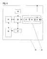
- ein schematisches Blockschaltbild der implantierbaren Therapievorrichtungaus Figur 1.
- FIG. 1:
- an implantable therapy device in the form of a pacemaker and an associated electrode lead and a heart in a schematic representation;
- FIG. 2:
- a simulated potential distribution for an arrangement according to Figure 1;
- FIG. 3:
- Impedance progress signals recorded with the arrangement of Figure 1 for an unloaded and a loaded state, including representation of a differential surface; and
- FIG. 4:
- a schematic block diagram of the implantable therapy device of Figure 1.
Die in Figur 1 dargestellte Anordnung umfasst einen Herzschrittmacher 10, anden zwei Elektrodenleitungen angeschlossen sind, nämlich eine atriale Elektrodenleitung12 und eine ventrikuläre Elektrodenleitung 14. Die ventrikuläre Elektrodenleitung14 besitzt eine Spitzenelektrode 16, die im Apex einer rechtenHerzkammer 18 eines schematisch dargestellten Herzens 20 platziert ist. Dieatriale Elektrodenleitung 12 ist im Bereich ihres distalen Endes j-förmig gebogenund besitzt eine atriale Spitzenelektrode 22, die im rechten Atrium 24 des Herzen20 angeordnet ist.The arrangement shown in FIG. 1 comprises a
Zur Aufnahme des hier interessierenden Impedanzverlaufs wird die Impedanzzwischen der ventrikulären Spitzenelektrode 16 und einer von einem Gehäuse 26des Schrittmachers 10 gebildeten Neutralelektrode gemessen. Die Neutralelektrode26 und die ventrikuläre Spitzenelektrode 16 sind dazu mit einem im Innerendes Gehäuses 26 angeordneten und in Figur 4 schematisch dargestellten Eingangsverstärker34 verbunden. Dieser Eingangsverstärker 34 besitzt eine automatischeVerstärkungssteuerung, die bewirkt, dass ein zwischen der Neutralelektrode26 und der ventrikulären Spitzenelektrode 16 gemessenes Impedanzsignalmit einem veränderlichen Verstärkungsfaktor verstärkt wird. Die automatischeVerstärkungssteuerung (Automatic Gain Control, AGC) bewirkt, dass dasAusgangssignal eines Impedanzsensors möglichst optimal an einen nachgeschaltetenAnalog-Digital-Wandler 36 angepasst wird. Impedanzsensor 32, Filtermit Eingangsverstärker 34 und Analog-Digital-Wandler 36 sind Bestandteil einerImpedanzmesseinheit 30, die als Ausgangssignal ein mit dem jeweils eingestelltenVerstärkungsfaktor skaliertes Impedanzverlaufssignal liefert. Dieses Impedanzverlaufssignalkann ein quasi-kontinuierliches Signal sein oder ein in größerenZeitabständen zeitabgetastetes, mittels einer Sample- und Hold-Schaltunggesampeltes Impedanzsignal sein. Die automatische Verstärkungssteuerungdient der optimalen Anpassung des Impedanzsensorausgangssignals an denAD-Wandler.To record the interest here impedance characteristic is the impedancebetween the
Im Inneren des Gehäuses 26 des Herzschrittmachers 10 ist außerdem ein Aktivitätssensor40 angeordnet, der geeignet ist, einen jeweiligen Aktivitätspegel einesPatienten zu erfassen und ein entsprechendes Aktivitätspegelsignal zu erzeugen.Der Aktivitätssensor 40 ist in einer bevorzugten Ausführungsform ein Accelerometer(Beschleunigungsmesser) und misst entsprechend die jeweilige Beschleunigungdes Herzschrittmachers 10.Inside the
Der Impedanzeinheit 30 und dem Aktivitätssensor 40 nachgeschaltet ist eineebenfalls im Gehäuse 26 angeordnete Auswerteeinheit 38.Downstream of the
Außerdem ist in dem Gehäuse 26 des Herzschrittmachers 10 ein Impedanzverlaufsspeicher42 angeordnet, der wenigstens mittelbar mit der Auswerteeinheit 38 verbunden ist und direkt mit der Impedanzmesseinheit 30 verbunden seinkann.In addition, in the
Die Auswerteeinheit 38 ist ausgebildet, ein Kontraktilitäts- beziehungsweise Kontraktilitätsdifferenzsignalaus zwei zu unterschiedlichen, aber gleich langen Zeiträumenerfassten Impedanzverlaufssignalen zu bilden. Dazu wird das Kontraktilitätsdifferenzsignalderart gebildet, dass es in etwa einer zwischen zwei Impedanzverlaufssignaleneingeschlossen Fläche entspricht (siehe Figur 3, DifferenzflächeDA). Das Ermitteln dieses Kontraktilitätsdifferenzsignals geschieht vorzugsweise,indem für die beiden Impedanzverlaufssignale zunächst ein Bezugs-Nullzeitpunktermittelt wird, beispielsweise gegeben durch eine jeweilige R-Zacke.Anschließend wird für eine Reihe aufeinanderfolgender Zeitabstände vomBezug-Nullzeitpunkt jeweils der Absolutwert der Differenz der beiden Impedanzverlaufssignalegebildet und schließlich die Summe dieser absoluten Differenzwerteüber die unterschiedlichen Zeitabstände gebildet. Auf diese Weise ergibtsich ein Kontraktilitätsdifferenzwert, der der Summe der Absolutwerte der Flächenintegraleder von den beiden Impedanzverlaufssignalen eingeschlossenenFlächen entspricht.The
Wie zuvor beschrieben, wird ein jeweiliger Impedanzverlauf unipolar gemessen.Wie Figur 2 zeigt, spiegelt ein derartiger, unipolar im Apex einer Herzkammergemessener Impedanzverlauf im wesentlichen den Verlauf der lokalen Impedanzum die Messelektrode (ventrikuläre Spitzenelektrode) herum wider.As described above, a respective impedance profile is measured unipolar.As Figure 2 shows, such a mirror, unipolar in the apex of a heart chambermeasured impedance curve substantially the course of the local impedancearound the measuring electrode (ventricular tip electrode).
Die beanspruchte Vorrichtung beruht auf der Beobachtung der ventrikulären Kontraktilitätmittels eines implantierten Herzschrittmachers oder Kardioverters/Defibrillatorsmittels intrakardialer Impedanzmessung. Die in Figur 2 abgebildeteBerechnung eines elektromagnetischen Feldes zeigt, dass ein unipolar mittelseiner in der Spitze der Herzkammer angeordneten Messelektrode gemessenerImpedanzwert Impedanzänderungen in naher Umgebung der Messelektrodewiderspiegelt.The claimed device is based on the observation of ventricular contractilityusing an implanted pacemaker or cardioverter / defibrillatorby intracardiac impedance measurement. The illustrated in Figure 2Calculation of an electromagnetic field shows that a unipolar meansa measuring electrode arranged in the tip of the heart chamberImpedance value Impedance changes in the vicinity of the measuring electrodereflects.
Das gemessene Impedanzsignal verändert sich während der Kontraktion desHerzens, weil Blut und das Myokardgewebe unterschiedliche elektrische Leitfähigkeitenbesitzen. Daher gibt der Zeitverlauf der unipolar gemessenen Impedanzdie Kontraktionsdynamik des ventrikulären Apex wieder. Es ist bekannt, dass dasunipolar gemessene rechtsventrikuläre Impedanzsignal gut mit dem Maximumder Druckänderung im rechten Ventrikel während eines Herzzyklusses übereinstimmt.The measured impedance signal changes during the contraction of theHeart, because blood and the myocardial tissue have different electrical conductivitieshave. Therefore, the time history of the unipolar measured impedancethe contraction dynamics of the ventricular apex again. It is known that theunipolar measured right ventricular impedance signal well with the maximumthe pressure change in the right ventricle coincides during a cardiac cycle.
Die Impedanzmessung selbst ist an sich bekannt. Ein konstanter, gepulsterStrom wird zwischen zwei Elektroden eingespeist und die daraus resultierendeSpannung wird zeitabgetastet, gefiltert, verstärkt und analog-digital gewandelt.The impedance measurement itself is known per se. A constant, pulsedPower is fed between two electrodes and the resultingVoltage is time-sampled, filtered, amplified and converted analog-to-digital.
Grundsätzlich können alle verfügbaren Elektroden als stromeinspeisende Elektrodenund als spannungsmessende Elektroden verwendet werden. Dies gilt insbesonderefür Anordnungen, bei denen mehr Elektroden vorgesehen sind als beider in Figur 1 abgebildeten Anordnung. Dabei können dieselben Elektroden sowohlzum Einspeisen des Stroms als auch zum Messen der Spannung verwendetwerden. Bei der in Figur 1 dargestellten, bevorzugten Ausführungsvariantewird die Spannung unipolar zwischen Herzschrittmachergehäuse 26 und ventrikulärerSpitzenelektrode 16 gemessen und auch der Messstrom wird zwischendiesen beiden Elektroden eingespeist. Anstelle der rechtsventrikulären Spitzenelektrodekann auch eine beispielsweise im Coronar-Sinus oder einer davon abzweigendenLateralvene angeordnete, linksventrikuläre Elektrode als Messelektrodedienen. Aus dem so gewonnenen Impedanzverlaufssignal wird das bereitsangesprochene Kontraktiliätssignal abgeleitet, und zwar vorzugsweise im Formeines Kontraktilitätsdifferenzsignals, welches durch Vergleich eines Impedanzsignalverlaufsim Ruhezustand des Patienten und eines Impedanzsignalverlaufsim Belastungszustand des Patienten gewonnen wird.In principle, all available electrodes can be used as current-feeding electrodesand used as voltage measuring electrodes. This is especially truefor arrangements in which more electrodes are provided than atthe arrangement shown in Figure 1. The same electrodes can bothused for feeding the current as well as measuring the voltagebecome. In the illustrated in Figure 1, preferred embodimentthe voltage becomes unipolar between
Wie zuvor bereits erwähnt, wird das Kontraktilitätsdifferenzsignal vorzugsweiseso gebildet, dass es die Differenzfläche widerspiegelt, die von zwei zu unterschiedlichenZeitpunkten aufgenommenen Impedanzverlaufssignalen eingeschlossenist. Impedanzverlaufssignale für einen Ruhezustand und einen Belastungszustand sind in Figur 3 dargestellt. Außerdem ist die von diesen beidenImpedanzverlaufssignalen eingeschlossene Differenzfläche DA dargestellt.As previously mentioned, the contractility difference signal is preferablyformed so that it reflects the difference surface, from two to differentTimes recorded impedance waveform signals includedis. Impedance history signals for a sleep state and a load stateare shown in FIG. Besides, those of these twoImpedance progress signals included differential area DA shown.
Wie bereits gesagt, ist die Differenzfläche die absolute Differenz zwischen demImpedanzverlaufssignal für den Ruhezustand des Patienten und dem Impedanzverlaufssignalfür den Belastungszustand des Patienten. Die Differenzfläche DA(Differential Area) lässt sich für zwei Impedanzverlaufssignale mit jeweils N Abtastwerten,für die jeweils ein Belastungsimpedanzwert Zbel (oder akuter ImpedanzwertZakut) und ein Ruheimpedanzwert ZRuhe (oder ReferenzimpedanzwertZRef) vorliegt wie folgt berechnen:
Die beiden Impedanzverlaufssignale beziehungsweise deren Abtastindizes i sinddabei auf einen geeigneten Bezugs-Nullzeitpunkt bezogen, beispielsweise jeweilsdie R-Zacke im zugehörigen Elektrokardiogramm.The two impedance progression signals or their scanning indices i arewhile referring to a suitable reference zero time, for example, respectivelythe R-wave in the associated electrocardiogram.
Anstelle eines Ruheimpedanzverlaufs mit Ruheimpedanzwerten ZRuhe und einesBelastungsimpedanzverlaufs mit Impedanzwerten Zbl kann auch ein beliebigerReferenzimpedanzverlauf als Referenzsignal mit Impedanzwerten ZRef und einjeweils aktueller Impedanzsignalverlauf mit Impedanzwerten Zakut herangezogenwerden.Instead of a return impedance curve with residual impedance values Zrest and a load impedance curve with impedance values Zbl, it is also possible to use any reference impedance curve as a reference signal with impedance values ZRef and a current impedance waveform with impedance values Zacute .
Die Impedanz wird jeweils kontinuierlich gemessen, beispielsweise zu jedemHerzschlag. Der aktuelle Impedanzverlauf wird als Kurzzeitmittelwert mit einerkleinen Zeitkonstante gebildet, beispielsweise einem 15/16 rekursiven Tiefpassfilter.Der Referenzimpedanzverlauf ist vorzugsweise ein gemittelter Ruheimpedanzsignalverlaufder nur aus solchen Impedanzsignalverläufen gebildet wird, dieim Ruhezustand des Patienten aufgenommen worden. Dieser Referenzimpedanzverlaufwird mit einer langen Zeitkonstante gefiltert, beispielsweise mit einem255/256 rekursiven Tiefpassfilter.The impedance is measured continuously, for example to eachHeartbeat. The current impedance curve is called a short-term average with asmall time constant formed, for example, a 15/16 recursive low-pass filter.The reference impedance curve is preferably an average Ruheimpedanzsignalverlaufis formed only from such impedance waveforms, thetaken in the resting state of the patient. This reference impedance curveis filtered with a long time constant, such as one255/256 recursive low-pass filter.
Ob sich ein Patient im Ruhezustand oder im Belastungszustand befindet, wirdanhand des Ausgangssignals des Aktivitätssensors, also des Accelerometersbestimmt. Dieses Accelerometer gibt ein Aktivitätspegelsignal aus, welches anzeigt,ob ein Patient ruht oder körperlich tätig ist. Aus dem Aktivitätspegelsignalkann ein Bewegungsflag Mflag (Motional Flag) abgeleitet werden, welches gesetztwird (Mflag =1), wenn ein Ausgangssignal des Accelerometers einen vorgegebenenGrenzwert überschreitet. Das Bewegungsflag Mflag wird zurückgesetzt(Mflag = 0), wenn das Ausgangssignal des Accelerometers einen vorgegebenenzweiten Grenzwert unterschreitet der erste und der zweite Grenzwert könnenunterschiedlich, aber auch identisch sein. Das Referenzimpedanzverlaufssignalwird nur dann gebildet, wenn das Bewegungsflag zurückgesetzt ist(Mflag=0).Whether a patient is in the resting state or in the stress state, willbased on the output of the activity sensor, so the accelerometercertainly. This accelerometer outputs an activity level signal indicatingwhether a patient is resting or physically active. From the activity level signala motion flag Mflag (Motional Flag) can be derived, which is setbecomes (Mflag = 1), if an output signal of the Accelerometer a givenExceeds limit. The motion flag Mflag is reset(Mflag = 0), if the output signal of the accelerometer is a preset valuesecond limit falls below the first and second limits candifferent, but also identical. The reference impedance waveformis formed only when the motion flag is reset(MFLAG = 0).
Das Mflag dient zur Steuerung der Mittelung des Referenz-Impedanzsignalverlaufs.Es soll nicht das Aktivitätspegelsignal ersetzen, da (z.B.zur Normierung des Kontraktilitätsreferenzsignals) das Aktivitätspegelsignal mehrereAbstufungen des Aktivitätspegels wiedergeben können soll.The Mflag is used to control the averaging of the reference impedance waveform.It is not intended to replace the activity level signal because (e.g.for normalizing the contractility reference signal) the activity level signal severalShould be able to reproduce gradations of the activity level.
Wenn im Belastungsfall des Patienten der erste Grenzwert überschritten wird unddas Mflag gesetzt ist (Mflag=1 ), wird die Bildung des Referenzimpedanzverlaufssignalsunterbrochen. Gleichzeitig wird eine durchschnittliche DifferenzflächeDAavg berechnet. Diese durchschnittliche Differenzfläche wird für eine vorgegebene,beispielsweise programmierbare Beobachtungsperiode, beispielsweise 24Stunden, bestimmt. Mit Beginn jeder neuen Beobachtungsperiode wird eine neuedurchschnittliche Differenzfläche DAavg berechnet.If the first limit value is exceeded and the Mflag is set (Mflag = 1) in the load case of the patient, the formation of the reference impedance progress signal is interrupted. At the same time an average difference area DAavg is calculated. This average differential area is determined for a predetermined, for example programmable observation period, for example 24 hours. At the beginning of each new observation period, a new average difference area DAavg is calculated.
Zusätzlich zur Berechnung der durchschnittlichen Differenzfläche DAavg kannauch ein durchschnittliches Aktivitätspegelsignal ermittelt werden. Jede durchschnittlicheDifferenzfläche (also jedes durchschnittliche Kontraktilitätsdifferenzsignal)kann dann mit dem jeweils zugehörigen Aktivitätspegelsignalwert normiertwerden.In addition to the calculation of the average difference area DAavg , an average activitylevel signal can also be determined. Each average differential area (ie, each average contractility difference signal) may then be normalized with the respective associated activity level signal value.
Alternativ kann die durchschnittliche Differenzfläche DAavg (der durchschnittlicheKontraktilitätsdifferenzsignalwert) für verschiedene Ausgangswertebereiche desAccelerometers berechnet werden. Außerdem ist es möglich, einen jeweiligenKontraktilitätsdifferenzsignalwert (die Differenzfläche) mit einem jeweils zugehörigenKurzzeit gemittelten Aktivitätspegelsignalwert zu normieren, bevor die gemittelteDifferenzfläche, also der gemittelte Kontraktilitätsdifferenzsignalwert gebildetwird. Durch diese Normierung wird sichergestellt, dass Beobachtungsperiodenmit unterschiedlichen Aktivitätspegeln vergleichbar sind.Alternatively, the average differential area DAavg (the average contractility difference signal value) may be calculated for different outputranges of the accelerometer. In addition, it is possible to normalize a respective contractility difference signal value (the differential area) with a respectively associated short-time averaged activity level signal value before the averaged differential area, ie the averaged contractility difference signal value, is formed. This standardization ensures that observation periods with different levels of activity are comparable.
Der zu messende Impedanzverlauf hängt nicht allein von der durch die Kontraktilitätbeeinflussten Kontraktionsdynamik ab, sondern auch von der Art des ventrikulärenEreignisses, also davon, ob die ventrikuläre Kontraktion eine natürlicheKontraktion ist, oder eine stimulierte. Der Impedanzverlauf (und der Kontraktionsverlauf)können bei stimulierten und bei intrinsischen, natürlichen ventrikulärenKontraktionen unterschiedlich sein. Daher wird die durchschnittliche DifferenzflächeDAavg in einer bevorzugten Ausführungsvariante für die beiden unterschiedlichenArten ventrikulärer Ereignisse - stimuliert und intrinsisch - separat berechnet.The impedance curve to be measured does not depend solely on the contractile dynamics influenced by contractility, but also on the nature of the ventricular event, ie whether the ventricular contraction is a natural contraction or a stimulated one. The impedance curve (and the contraction curve) may be different in stimulated and in intrinsic, natural ventricular contractions. Therefore, in a preferred embodiment, the average differential area DAavg for the two different types of ventricular events - stimulated and intrinsic - is calculated separately.
Zu diesem Zweck sind in der bevorzugten Ausführungsvariante die Auswerteeinheitund eine Therapiesteuereinheit 44, die beispielsweise die Abgabe von Stimulationsimpulsensteuert, derart wenigstens mittelbar miteinander verbunden, dassdie Therapiesteuereinheit 44 an die Auswerteeinheit 38 ein Signal abgibt, wenneine ventrikuläre Stimulation erfolgt. Dieses Signal ist in einer besonders bevorzugtenAusführungsvariante ein an sich bekanntes Markersignal zum Kennzeichnenventrikulärer Stimulation.For this purpose, in the preferred embodiment, the evaluation unitand a
Die auf diese Weise bestimmte durchschnittliche Differenzfläche DAavg ist einIndikator für die durchschnittliche Kontraktilitätsänderung während einer körperlichenBelastung eines einzelnen Patienten. Dieser Wert kann auf die nachfolgendbeschriebene Weise für diagnostische und therapeutische Zwecke genutzt werden.The thus determined average differential area DAavg is an indicator of the average change in contractility during a physical exercise of a single patient. This value can be used in the manner described below for diagnostic and therapeutic purposes.
Grundsätzlich ist es auch möglich, ein die Kontraktilität kennzeichnendes Signalauf andere Weise aus dem Impedanzsignal zu gewinnen, so wie dies beispielsweisebei dem eingangs zitierten Stand der Technik geschieht (beispielsweiseper Impedanz-Plethysmographie oder durch Bilden der zweiten Ableitung desImpedanzsignals). Die Unterscheidung zwischen dem Ruhezustand und einemBelastungszustand eines Patienten wie auch die Mittelwertbildung über eine vorgegebeneZeitperiode sollen auch in diesen Fällen (Bestimmung der Kontraktilitätaus der Impedanz auf anderem Weg als über die Differenzfläche) so erfolgen,wie hier beschrieben.In principle, it is also possible to signal the contractilityotherwise from the impedance signal, such as thisin the cited prior art (for exampleby impedance plethysmography or by making the second derivative of theImpedance signal). The distinction between hibernation and aStress condition of a patient as well as the averaging over a givenTime period should also in these cases (determination of contractilityfrom the impedance in a different way than via the differential surface),as described here.
Vorzugsweise umfasst der Herzschrittmacher 16 eine Therapiesteuereinheit 44,die ausgebildet ist, einen oder mehrere von ihr zu steuernde Stimulationsparameterwie der Stimulationsmodus - biventrikulär, rechtsventrikulär, linksventrikulär,etc. - eine atrio-ventrikuläre Verzögerungszeit oder eine interventrikuläre Verzögerungszeitin Abhängigkeit des jeweiligen Kontraktilitätssignals so einzustellen,dass sich jeweils eine größtmögliche Kontraktilität ergibt. Diese Optimierung derStimulationsparameter durch Therapiesteuereinheit 44 erfolgt dabei vorzugsweisenach Art einer Regelung in rekursiver Weise, indem ein zunächst vorgegebenerStimulationsparameter (beispielsweise für die atrio-ventrikuläre Verzögerungszeitoder die interventrikuläre Verzögerungszeit) schrittweise verändert wirdund immer derjenige Wert des Steuerparameters als Ausgangspunkt für dienächste Veränderung herangezogen wird, für den sich jeweils die höchste Kontraktilitätergeben hat. In diesem Sinne greift die Therapiesteuereinheit 44 aufeinen Speicher 42 für das Kontraktilitätssignal zu, welches in der bevorzugtenAusführungsvariante durch den Verlauf der durchschnittlichen DifferenzflächeDAavg gegeben ist.The
Diese Therapiesteuereinheit 44 kann zusätzlich wie in der zuvor erwähnten Weisemit der Auswerteeinheit 38 derart verbunden sein kann, dass die Auswerteeinheitein Markersignal empfängt, wenn eine ventrikuläre Stimulation erfolgt.This
In einer weiter bevorzugten Ausführungsvariante weist der Speicher 42 für dasKontraktilitätssignal getrennte Speicherbereiche für die Differenzfläche DAavg für beide Arten ventrikulärer Ereignisse und für die Anzahl der Differenzflächenwerte,die zur Bildung der jeweiligen durchschnittlichen Differenzfläche DAavg beigetragenhaben, auf. Dieser Speicher ist vorzugsweise mit einer Telemetrieeinheit46 verbunden, so dass die in dem Speicher 42 gespeicherten Werte telemetrischdurch einen Arzt abgefragt werden können.In a further preferred embodiment, the contractilitysignal memory 42 has separate storage areas for the differential area DAavg for both types of ventricular events and for the number of differential areavalues that contributed to the formation of the respective average difference area DAavg . This memory is preferably connected to a
Neben Speicherbereichen für die zuletzt genannten Daten in bezug auf das Kontraktilitätssignal(die Differenzfläche) ist vorzugsweise ein weiterer Speicherbereichfür die zugehörigen Aktivitätspegelsignalwerte vorgesehen. Die derart durchden Arzt telemetrisch abzufragenden Daten können dann auf einem Bildschirmgraphisch dargestellt werden und die Diagnose durch den Arzt unterstützen.In addition to memory areas for the last-mentioned data with respect to the contractility signal(the differential area) is preferably another storage areafor the associated activity level signal values. The way throughThe doctor can then telemeter data retrieved on a screengraphically and assist the diagnosis by the physician.
Mit Hilfe der telemetrischen Anbindung des Herzschrittmachers 16 an ein externesGerät können die gemittelten Kontraktilitäts- und Aktivitätspegelsignale auchim Rahmen eines sogenannten Homemonitoring regelmäßig, beispielsweise täglich,übermittelt werden. In diesem Falle werden die an ein externes Gerät übertragenenDaten von diesem externen Gerät auf an sich bekannte Weise an einzentrales Service-Center übermittelt und können mit dort zuvor bereits gespeichertenDaten korreliert werden.With the help of the telemetric connection of the
Die Therapiesteuereinheit kann darüber hinaus so ausgebildet sein, dass sie vonsich aus eine Datenübertragung auslöst, wenn ein besonderes Ereignis, beispielsweiseein Alarm-Zustand, vorliegt. Dieses besondere Ereignis kann beispielsweiseeine detektierte Arrhythmie sein. Genauso ist es möglich, dass dasbesondere Ereignis eine telemetrisch empfangene Anforderung seitens einesArztes oder des Patienten selbst ist. Im Zusammenhang mit der Überwachungund der Auswertung des Kontraktilitätssignals kann als besonderes, eine telemetrischeVerbindung auslösendes Ereignis auch eine signifikante Veränderung desKontraktilitätssignals, das heißt im bevorzugten Fall des Wertes der Differenzflächeselbst sein.The therapy control unit may also be designed to be ofis a data transfer triggers when a special event, for examplean alarm condition exists. For example, this special eventbe a detected arrhythmia. It is equally possible that thatspecial event a telemetrically received request from aDoctor or the patient himself. In the context of surveillanceand the evaluation of the contractility signal may be special, a telemetricConnection triggering event also a significant change of theContractility signal, that is, in the preferred case, the value of the differential areabe yourself.
Die Beobachtung der mittels eines implantierten Elektrotherapiegerätes ermitteltenKontraktilität auf die zuvor beschriebene Weise kann für verschiedene diagnostische oder therapeutische Zwecke genutzt werden. Zu den diagnostischenMöglichkeiten zählen:
- eine generelle Überwachung von Patienten mit Herzversagen (HF-Patienten)mittels der gespeicherten und telemetrisch übertragenen Daten
- Überwachung der HF-Patienten mittels der Homonitoring-Daten und derzuvor erwähnten Alarm-Funktionalität
- Überwachung einer Medikation, beispielsweise wenn Medikamente mitpositiver oder negativer inotroper Wirkung verabreicht werden
- Überwachung einer Resynchronisationstherapie; und/oder
- Beobachtung von Patienten, die ein erhöhtes Risiko für plötzliche Kontraktilitätsänderungenzeigen, beispielsweise Patienten mit dem Risiko einesMyokardinfarkts oder einer Ischämie.
- a general monitoring of patients with heart failure (HF patients) using the stored and telemetrically transmitted data
- Monitoring the HF patients using the homonitoring data and the aforementioned alarm functionality
- Monitoring a medication, for example, when administering drugs with positive or negative inotropic effects
- Monitoring a resynchronization therapy; and or
- Monitoring of patients presenting an increased risk of sudden changes in contractility, for example, patients at risk of myocardial infarction or ischemia.
Die therapeutischen Optionen sind:
- Anpassung des Stimulationsmodus an detektierte Kontraktilitätsänderungen,beispielsweise Umschalten zwischen rechtsventrikulärer, linksventrikulärerund biventrikulärer Stimulation, und
- Anpassung anderer Stimulations- oder Defibrillationsparameter beispielsweisesolcher Zeitparameter wie die bereits erwähnte atrio-ventrikuläreVerzögerungszeit, die biventrikuläre Verzögerungszeit aber auch der Stimulationsrateselbst oder zusäzlich oder alternativ
- Anpassung oder Steuerung einer Medikamententherapie durch den Arzt.
- Adaptation of the stimulation mode to detected contractility changes, for example switching between right ventricular, left ventricular and biventricular stimulation, and
- Adaptation of other stimulation or defibrillation parameters, for example such time parameters as the already mentioned atrio-ventricular delay time, the biventricular delay time but also the stimulation rate itself or additionally or alternatively
- Adaptation or control of drug therapy by the doctor.
Darüber hinaus kann ein derartiger Herzschrittmacher auch als akuter Sensorverwendet werden, beispielsweise während einer elektrophysiologischen Untersuchung, wenn der Patient permanent implantierte Elektrodenleitungen besitzt.Die Reaktion des Herzens auf eine temporäre Anwendung eines positivinotropenMedikaments, beispielsweise Dobutamin, oder auf eine standardisierteBelastung, kann ebenfalls getestet werden. Verschiedene Untersuchungen aneinem Patienten können miteinander verglichen werden und die Änderungen derjeweiligen Belastungsreaktion ausgewertet werden. Diese Anwendung dient derDiagnose von Herzinsuffizienz, der regelmäßigen Beobachtung der Verschlechterungoder Verbesserung von Herzfehlern und zum Testen der allgemeinenKontraktilität.In addition, such a pacemaker can also be used as an acute sensorused, for example during an electrophysiological examination,if the patient has permanently implanted electrode leads.The reaction of the heart to a temporary application of a positivinotropicDrug, such as dobutamine, or on a standardizedLoad, can also be tested. Various investigationsa patient can be compared with each other and the changes of therespective load response can be evaluated. This application is for theDiagnosis of heart failure, the regular observation of deteriorationor improving heart failure and testing the generalContractility.
Claims (18)
Translated fromGermaneinem Gehäuse, welches
einen Elektrodenleitungsanschluss für den Anschluss wenigstens einer intrakardialzu platzierenden Elektrodenleitung aufweist, die wenigstens eineMesselektrode für die Aufnahme eines intrakardialen Impedanzsignals aufweist,
wobei in dem Gehäuse
ein Aktivitätssensor, der ausgebildet ist, ein Aktivitätspegelsignal zu erzeugen,dessen jeweilige Aktivitätspegelsignalwerte im implantierten Zustanddes Therapiegeräts von einer körperlichen Aktivität eines Patienten abhängen,
eine Impedanz- oder Leitfähigkeitsmesseinheit, die ausgebildet ist, ein uni-oderbipolares Impedanz- oder Leitfähigkeitssignalsignal durch Messen einesImpedanz- oder Leitfähigkeitswertes zwischen einer Neutralelektrodeund einer Messelektrode oder zwischen zwei Messelektroden zu erzeugensowie
eine Auswerteeinheit angeordnet sind,
dadurch gekennzeichnet, dass die Auswerteeinheit mit der Impedanz- oderLeitfähigkeitsmesseinheit und dem Aktivitätssensor verbunden und zumAuswerten des von der Impedanz- oder Leitfähigkeitsmesseinheit erzeugtenImpedanz- oder Leitfähigkeitssignals und des jeweils zeitlich zugeordnetenAktivitätspegelsignals und zum Erzeugen und Ausgeben eines Kontraktilitätssignalsderart ausgebildet ist, dass das Kontraktilitätssignal ausdem Impedanz- oder Leitfähigkeitssignal sowie dem Aktivitätspegelsignal abgeleitet ist und den jeweiligen kontraktilen Zustand eines Herzens zugeordnetzu einem Aktivitätspegelsignalwert widerspiegelt .Implantable electrotherapy device, in particular pacemaker, defibrillator or the like, with
a housing, which
an electrode lead terminal for the connection of at least one intracardiac electrode lead to be placed, which has at least one measuring electrode for receiving an intracardiac impedance signal,
being in the housing
an activity sensor configured to generate an activity level signal whose respective activity level signal values in the implanted state of the therapy device depend on a physical activity of a patient,
an impedance or conductivity measuring unit configured to generate a uni- or bipolar impedance or conductivity signal by measuring an impedance or conductivity value between a neutral electrode and a measuring electrode or between two measuring electrodes, and
an evaluation unit are arranged,
characterized in that the evaluation unit is connected to the impedance or conductivity measuring unit and the activity sensor and designed to evaluate the impedance or conductivity signal generated by the impedance or conductivity measuring unit and the respectively temporally associated activity level signal and for generating and outputting a contractility signal such that Contractility signal is derived from the impedance or conductivity signal and the activity level signal and reflects the respective contractile state of a heart associated with an activity level signal value.
Applications Claiming Priority (4)
| Application Number | Priority Date | Filing Date | Title |
|---|---|---|---|
| DE102004018783 | 2004-04-14 | ||
| DE102004018783 | 2004-04-14 | ||
| DE102004034337 | 2004-07-09 | ||
| DE102004034337ADE102004034337A1 (en) | 2004-04-14 | 2004-07-09 | Electrotherapy device |
Publications (2)
| Publication Number | Publication Date |
|---|---|
| EP1586348A1true EP1586348A1 (en) | 2005-10-19 |
| EP1586348B1 EP1586348B1 (en) | 2008-04-16 |
Family
ID=34938421
Family Applications (1)
| Application Number | Title | Priority Date | Filing Date |
|---|---|---|---|
| EP05090083AExpired - LifetimeEP1586348B1 (en) | 2004-04-14 | 2005-03-31 | Electrotherapeutic apparatus |
Country Status (4)
| Country | Link |
|---|---|
| US (1) | US7519422B2 (en) |
| EP (1) | EP1586348B1 (en) |
| AT (1) | ATE392230T1 (en) |
| DE (2) | DE102004034337A1 (en) |
Families Citing this family (49)
| Publication number | Priority date | Publication date | Assignee | Title |
|---|---|---|---|---|
| DE10257156A1 (en)* | 2002-12-02 | 2004-06-17 | Biotronik Meß- und Therapiegeräte GmbH & Co. Ingenieurbüro Berlin | Pacemaker |
| DE102005047320A1 (en) | 2005-09-30 | 2007-04-05 | Biotronik Crm Patent Ag | Detector for atrial flicker and flutter |
| ATE422375T1 (en)* | 2006-06-15 | 2009-02-15 | Ela Medical Sa | ACTIVE MEDICAL IMPLANT, IN PARTICULAR A DEVICE FOR STIMULATION, RESYNCHRONIZATION, DEFIBRILLATION AND/OR CARDIOVERSION, COMPRISING MEANS OF PREDICTIVE WARNING OF EXCESSION OF THE PATIENT'S MEDICAL CONDITION |
| US7848822B2 (en)* | 2006-11-14 | 2010-12-07 | Cardiac Pacemakers, Inc. | Cardiac force sensor and methods of use |
| US7769436B1 (en) | 2007-06-04 | 2010-08-03 | Pacesetter, Inc. | System and method for adaptively adjusting cardiac ischemia detection thresholds and other detection thresholds used by an implantable medical device |
| US9308307B2 (en) | 2007-09-13 | 2016-04-12 | Fresenius Medical Care Holdings, Inc. | Manifold diaphragms |
| US9358331B2 (en) | 2007-09-13 | 2016-06-07 | Fresenius Medical Care Holdings, Inc. | Portable dialysis machine with improved reservoir heating system |
| US8240636B2 (en) | 2009-01-12 | 2012-08-14 | Fresenius Medical Care Holdings, Inc. | Valve system |
| US8597505B2 (en) | 2007-09-13 | 2013-12-03 | Fresenius Medical Care Holdings, Inc. | Portable dialysis machine |
| US8105487B2 (en) | 2007-09-25 | 2012-01-31 | Fresenius Medical Care Holdings, Inc. | Manifolds for use in conducting dialysis |
| US8649864B2 (en)* | 2007-10-16 | 2014-02-11 | Biotronik Crm Patent Ag | Implantable heart stimulator providing long term cardiac monitoring with automatic notification |
| CA3057807C (en) | 2007-11-29 | 2021-04-20 | Thomas P. Robinson | System and method for conducting hemodialysis and hemofiltration |
| EP3586946B1 (en) | 2008-10-07 | 2023-03-29 | Fresenius Medical Care Holdings, Inc. | Priming system and method for dialysis systems |
| EA024555B1 (en) | 2008-10-30 | 2016-09-30 | Фрезениус Медикал Кеа Холдингс, Инк. | Modular, portable dialysis system |
| US8374690B2 (en)* | 2009-03-10 | 2013-02-12 | Ari Licensing | Apparatus for determining health of an individual |
| WO2010114932A1 (en) | 2009-03-31 | 2010-10-07 | Xcorporeal, Inc. | Modular reservoir assembly for a hemodialysis and hemofiltration system |
| US8707782B2 (en) | 2009-06-30 | 2014-04-29 | Orthosensor Inc | Prosthetic component for monitoring synovial fluid and method |
| US9839390B2 (en) | 2009-06-30 | 2017-12-12 | Orthosensor Inc. | Prosthetic component having a compliant surface |
| US9462964B2 (en) | 2011-09-23 | 2016-10-11 | Orthosensor Inc | Small form factor muscular-skeletal parameter measurement system |
| US8714009B2 (en) | 2010-06-29 | 2014-05-06 | Orthosensor Inc. | Shielded capacitor sensor system for medical applications and method |
| US8720270B2 (en) | 2010-06-29 | 2014-05-13 | Ortho Sensor Inc. | Prosthetic component for monitoring joint health |
| US20100331679A1 (en)* | 2009-06-30 | 2010-12-30 | Orthosensor | Pulsed echo sensing device and method for an orthopedic joint |
| US8701484B2 (en) | 2010-06-29 | 2014-04-22 | Orthosensor Inc. | Small form factor medical sensor structure and method therefor |
| US8826733B2 (en) | 2009-06-30 | 2014-09-09 | Orthosensor Inc | Sensored prosthetic component and method |
| US8679186B2 (en) | 2010-06-29 | 2014-03-25 | Ortho Sensor Inc. | Hermetically sealed prosthetic component and method therefor |
| US9259179B2 (en) | 2012-02-27 | 2016-02-16 | Orthosensor Inc. | Prosthetic knee joint measurement system including energy harvesting and method therefor |
| US8421479B2 (en) | 2009-06-30 | 2013-04-16 | Navisense | Pulsed echo propagation device and method for measuring a parameter |
| US8321017B2 (en)* | 2009-07-08 | 2012-11-27 | Pacesetter, Inc. | Electromechanical delay (EMD) monitoring devices, systems and methods |
| US8435186B2 (en)* | 2010-01-29 | 2013-05-07 | Medtronic, Inc. | Quantifying autonomic tone with thoracic impedance |
| EP2364640A1 (en)* | 2010-03-11 | 2011-09-14 | BIOTRONIK SE & Co. KG | Monitoring device and method for operating a monitoring device |
| US9161717B2 (en) | 2011-09-23 | 2015-10-20 | Orthosensor Inc. | Orthopedic insert measuring system having a sealed cavity |
| US8652048B2 (en) | 2010-08-06 | 2014-02-18 | Biotronik Se & Co. Kg | Implant and system for predicting decompensation |
| EP2415396B1 (en) | 2010-08-06 | 2016-08-17 | BIOTRONIK SE & Co. KG | Heart monitor |
| US8965495B2 (en) | 2010-08-30 | 2015-02-24 | Biotronik Se & Co. Kg | Implantable electronic therapy device |
| US9839374B2 (en) | 2011-09-23 | 2017-12-12 | Orthosensor Inc. | System and method for vertebral load and location sensing |
| US9414940B2 (en) | 2011-09-23 | 2016-08-16 | Orthosensor Inc. | Sensored head for a measurement tool for the muscular-skeletal system |
| US8911448B2 (en) | 2011-09-23 | 2014-12-16 | Orthosensor, Inc | Device and method for enabling an orthopedic tool for parameter measurement |
| US9271675B2 (en) | 2012-02-27 | 2016-03-01 | Orthosensor Inc. | Muscular-skeletal joint stability detection and method therefor |
| US9844335B2 (en) | 2012-02-27 | 2017-12-19 | Orthosensor Inc | Measurement device for the muscular-skeletal system having load distribution plates |
| US9622701B2 (en) | 2012-02-27 | 2017-04-18 | Orthosensor Inc | Muscular-skeletal joint stability detection and method therefor |
| US9237885B2 (en) | 2012-11-09 | 2016-01-19 | Orthosensor Inc. | Muscular-skeletal tracking system and method |
| US9201036B2 (en) | 2012-12-21 | 2015-12-01 | Fresenius Medical Care Holdings, Inc. | Method and system of monitoring electrolyte levels and composition using capacitance or induction |
| US9157786B2 (en) | 2012-12-24 | 2015-10-13 | Fresenius Medical Care Holdings, Inc. | Load suspension and weighing system for a dialysis machine reservoir |
| US11793424B2 (en) | 2013-03-18 | 2023-10-24 | Orthosensor, Inc. | Kinetic assessment and alignment of the muscular-skeletal system and method therefor |
| US9408557B2 (en) | 2013-03-18 | 2016-08-09 | Orthosensor Inc. | System and method to change a contact point of the muscular-skeletal system |
| US9354640B2 (en) | 2013-11-11 | 2016-05-31 | Fresenius Medical Care Holdings, Inc. | Smart actuator for valve |
| US10893955B2 (en) | 2017-09-14 | 2021-01-19 | Orthosensor Inc. | Non-symmetrical insert sensing system and method therefor |
| US11812978B2 (en) | 2019-10-15 | 2023-11-14 | Orthosensor Inc. | Knee balancing system using patient specific instruments |
| EP4619090A1 (en)* | 2022-11-16 | 2025-09-24 | BIOTRONIK SE & Co. KG | Implantable medical stimulation device for performing a cardiac pacing in a patient |
Citations (9)
| Publication number | Priority date | Publication date | Assignee | Title |
|---|---|---|---|---|
| US4674518A (en) | 1985-09-06 | 1987-06-23 | Cardiac Pacemakers, Inc. | Method and apparatus for measuring ventricular volume |
| US4773401A (en)* | 1987-08-21 | 1988-09-27 | Cardiac Pacemakers, Inc. | Physiologic control of pacemaker rate using pre-ejection interval as the controlling parameter |
| EP0447024A2 (en)* | 1990-03-08 | 1991-09-18 | Cardiac Pacemakers, Inc. | Rate adaptive cardiac pacer incorporating switched capacitor filter with cutoff frequency determined by heart rate |
| US5417717A (en) | 1991-11-04 | 1995-05-23 | Cardiac Pacemakers, Inc. | Implantable cardiac function monitor and stimulator for diagnosis and therapy delivery |
| EP0793976A2 (en)* | 1996-03-04 | 1997-09-10 | BIOTRONIK Mess- und Therapiegeräte GmbH & Co Ingenieurbüro Berlin | Rate adaptive pacemaker |
| US5800467A (en)* | 1995-12-15 | 1998-09-01 | Pacesetter, Inc. | Cardio-synchronous impedance measurement system for an implantable stimulation device |
| US6154674A (en)* | 1998-01-29 | 2000-11-28 | Biotronik Mess-Und Therapiegeraete Gmbh & Co. Ingenieurbuero Berlin | Self-calibrating adaptive-rate cardiac pacemaker |
| EP1062974A2 (en) | 1999-06-23 | 2000-12-27 | BIOTRONIK Mess- und Therapiegeräte GmbH & Co Ingenieurbüro Berlin | Method of determining of a variable control parameter of an implantable medical device |
| US20040138718A1 (en)* | 2002-10-25 | 2004-07-15 | Marcel Limousin | Management of respiratory pauses of hypopnea in an active implantable medical device of the cardiac pacemaker, defibrillator, cardiovertor or multisite device type |
Family Cites Families (4)
| Publication number | Priority date | Publication date | Assignee | Title |
|---|---|---|---|---|
| DE8713037U1 (en)* | 1987-09-28 | 1988-04-14 | Alt, Eckhard, Dr., 8000 München | Medical device for determining physiological function parameters |
| DE4111505C2 (en)* | 1991-04-09 | 1997-04-17 | Pacesetter Ab | Arrangement for determining a physiological parameter from a cardiac information signal |
| EP1142608A2 (en)* | 2000-04-05 | 2001-10-10 | Pacesetter, Inc. | System and method for prevention of recurrent vasovagal syncope using cardiac pacing |
| US7096064B2 (en)* | 2001-08-28 | 2006-08-22 | Medtronic, Inc. | Implantable medical device for treating cardiac mechanical dysfunction by electrical stimulation |
- 2004
- 2004-07-09DEDE102004034337Apatent/DE102004034337A1/ennot_activeWithdrawn
- 2005
- 2005-03-31EPEP05090083Apatent/EP1586348B1/ennot_activeExpired - Lifetime
- 2005-03-31ATAT05090083Tpatent/ATE392230T1/ennot_activeIP Right Cessation
- 2005-03-31DEDE502005003696Tpatent/DE502005003696D1/ennot_activeExpired - Lifetime
- 2005-04-12USUS11/104,275patent/US7519422B2/ennot_activeExpired - Fee Related
Patent Citations (9)
| Publication number | Priority date | Publication date | Assignee | Title |
|---|---|---|---|---|
| US4674518A (en) | 1985-09-06 | 1987-06-23 | Cardiac Pacemakers, Inc. | Method and apparatus for measuring ventricular volume |
| US4773401A (en)* | 1987-08-21 | 1988-09-27 | Cardiac Pacemakers, Inc. | Physiologic control of pacemaker rate using pre-ejection interval as the controlling parameter |
| EP0447024A2 (en)* | 1990-03-08 | 1991-09-18 | Cardiac Pacemakers, Inc. | Rate adaptive cardiac pacer incorporating switched capacitor filter with cutoff frequency determined by heart rate |
| US5417717A (en) | 1991-11-04 | 1995-05-23 | Cardiac Pacemakers, Inc. | Implantable cardiac function monitor and stimulator for diagnosis and therapy delivery |
| US5800467A (en)* | 1995-12-15 | 1998-09-01 | Pacesetter, Inc. | Cardio-synchronous impedance measurement system for an implantable stimulation device |
| EP0793976A2 (en)* | 1996-03-04 | 1997-09-10 | BIOTRONIK Mess- und Therapiegeräte GmbH & Co Ingenieurbüro Berlin | Rate adaptive pacemaker |
| US6154674A (en)* | 1998-01-29 | 2000-11-28 | Biotronik Mess-Und Therapiegeraete Gmbh & Co. Ingenieurbuero Berlin | Self-calibrating adaptive-rate cardiac pacemaker |
| EP1062974A2 (en) | 1999-06-23 | 2000-12-27 | BIOTRONIK Mess- und Therapiegeräte GmbH & Co Ingenieurbüro Berlin | Method of determining of a variable control parameter of an implantable medical device |
| US20040138718A1 (en)* | 2002-10-25 | 2004-07-15 | Marcel Limousin | Management of respiratory pauses of hypopnea in an active implantable medical device of the cardiac pacemaker, defibrillator, cardiovertor or multisite device type |
Also Published As
| Publication number | Publication date |
|---|---|
| DE102004034337A1 (en) | 2005-11-03 |
| EP1586348B1 (en) | 2008-04-16 |
| US20050240233A1 (en) | 2005-10-27 |
| US7519422B2 (en) | 2009-04-14 |
| DE502005003696D1 (en) | 2008-05-29 |
| ATE392230T1 (en) | 2008-05-15 |
Similar Documents
| Publication | Publication Date | Title |
|---|---|---|
| EP1586348B1 (en) | Electrotherapeutic apparatus | |
| EP1510173B1 (en) | Intracardial impedance measuring device | |
| EP1762270B1 (en) | Device for determining cardiac parameters | |
| EP2433565B1 (en) | Implantable medical device | |
| EP2060299B1 (en) | Biventricular heart stimulator | |
| DE69213657T2 (en) | Implantable device for monitoring and stimulating the heart for diagnosis and therapy | |
| DE10119395A1 (en) | Pacemaking patients heart using implantable medical device, involves detecting heart state, e.g. ischaemia, depending on speed of sampled blood flow through coronary sinus of patient's heart | |
| EP2415396B1 (en) | Heart monitor | |
| EP2540341B1 (en) | Cardiac stimulator for delivery of cardiac contractility modulation therapy | |
| EP1955650B1 (en) | Implantable medical device | |
| EP2628503B1 (en) | Cardiac stimulator for cardiac contractility modulation | |
| EP2676697B1 (en) | Dislocation sensor | |
| EP2548501B1 (en) | Device and method for monitoring physiological signals | |
| DE602004012899T2 (en) | IDENTIFICATION AND / OR MONITORING OF DIASTOLIC HEART FAILURE | |
| EP2111892B1 (en) | Anti-tachycardic heart stimulator | |
| EP2422843B1 (en) | Implantable electronic therapy device | |
| EP2181648A2 (en) | Single chamber heart simulator | |
| DE102007057227B4 (en) | Cardiac stimulation arrangement | |
| EP2111893A1 (en) | Ventricular heart stimulator | |
| DE102008002293A1 (en) | Anti-tachycardia cardiac stimulator | |
| DE10361143A1 (en) | Intracardiac impedance measurement arrangement | |
| EP2140910A1 (en) | Heart stimulator for treating cardiac tachyarrhythmias | |
| EP2174688B1 (en) | Device for Processing Cardiac Signals | |
| EP2075033B1 (en) | Biventricular heart stimulator | |
| EP2327447A1 (en) | Biventricular cardiac stimulator |
Legal Events
| Date | Code | Title | Description |
|---|---|---|---|
| PUAI | Public reference made under article 153(3) epc to a published international application that has entered the european phase | Free format text:ORIGINAL CODE: 0009012 | |
| AK | Designated contracting states | Kind code of ref document:A1 Designated state(s):AT BE BG CH CY CZ DE DK EE ES FI FR GB GR HU IE IS IT LI LT LU MC NL PL PT RO SE SI SK TR | |
| AX | Request for extension of the european patent | Extension state:AL BA HR LV MK YU | |
| RAP1 | Party data changed (applicant data changed or rights of an application transferred) | Owner name:BIOTRONIK CRM PATENT AG | |
| 17P | Request for examination filed | Effective date:20060419 | |
| AKX | Designation fees paid | Designated state(s):AT BE BG CH CY CZ DE DK EE ES FI FR GB GR HU IE IS IT LI LT LU MC NL PL PT RO SE SI SK TR | |
| 17Q | First examination report despatched | Effective date:20060626 | |
| GRAP | Despatch of communication of intention to grant a patent | Free format text:ORIGINAL CODE: EPIDOSNIGR1 | |
| GRAS | Grant fee paid | Free format text:ORIGINAL CODE: EPIDOSNIGR3 | |
| GRAA | (expected) grant | Free format text:ORIGINAL CODE: 0009210 | |
| AK | Designated contracting states | Kind code of ref document:B1 Designated state(s):AT BE BG CH CY CZ DE DK EE ES FI FR GB GR HU IE IS IT LI LT LU MC NL PL PT RO SE SI SK TR | |
| REG | Reference to a national code | Ref country code:CH Ref legal event code:EP | |
| REG | Reference to a national code | Ref country code:SE Ref legal event code:TRGR | |
| GBT | Gb: translation of ep patent filed (gb section 77(6)(a)/1977) | Effective date:20080429 | |
| REG | Reference to a national code | Ref country code:IE Ref legal event code:FG4D Free format text:LANGUAGE OF EP DOCUMENT: GERMAN | |
| REF | Corresponds to: | Ref document number:502005003696 Country of ref document:DE Date of ref document:20080529 Kind code of ref document:P | |
| PG25 | Lapsed in a contracting state [announced via postgrant information from national office to epo] | Ref country code:SI Free format text:LAPSE BECAUSE OF FAILURE TO SUBMIT A TRANSLATION OF THE DESCRIPTION OR TO PAY THE FEE WITHIN THE PRESCRIBED TIME-LIMIT Effective date:20080416 | |
| ET | Fr: translation filed | ||
| PG25 | Lapsed in a contracting state [announced via postgrant information from national office to epo] | Ref country code:PT Free format text:LAPSE BECAUSE OF FAILURE TO SUBMIT A TRANSLATION OF THE DESCRIPTION OR TO PAY THE FEE WITHIN THE PRESCRIBED TIME-LIMIT Effective date:20080916 Ref country code:BG Free format text:LAPSE BECAUSE OF FAILURE TO SUBMIT A TRANSLATION OF THE DESCRIPTION OR TO PAY THE FEE WITHIN THE PRESCRIBED TIME-LIMIT Effective date:20080716 Ref country code:FI Free format text:LAPSE BECAUSE OF FAILURE TO SUBMIT A TRANSLATION OF THE DESCRIPTION OR TO PAY THE FEE WITHIN THE PRESCRIBED TIME-LIMIT Effective date:20080416 Ref country code:ES Free format text:LAPSE BECAUSE OF FAILURE TO SUBMIT A TRANSLATION OF THE DESCRIPTION OR TO PAY THE FEE WITHIN THE PRESCRIBED TIME-LIMIT Effective date:20080727 | |
| PG25 | Lapsed in a contracting state [announced via postgrant information from national office to epo] | Ref country code:PL Free format text:LAPSE BECAUSE OF FAILURE TO SUBMIT A TRANSLATION OF THE DESCRIPTION OR TO PAY THE FEE WITHIN THE PRESCRIBED TIME-LIMIT Effective date:20080416 | |
| REG | Reference to a national code | Ref country code:IE Ref legal event code:FD4D | |
| PG25 | Lapsed in a contracting state [announced via postgrant information from national office to epo] | Ref country code:IS Free format text:LAPSE BECAUSE OF FAILURE TO SUBMIT A TRANSLATION OF THE DESCRIPTION OR TO PAY THE FEE WITHIN THE PRESCRIBED TIME-LIMIT Effective date:20080816 | |
| PG25 | Lapsed in a contracting state [announced via postgrant information from national office to epo] | Ref country code:CZ Free format text:LAPSE BECAUSE OF FAILURE TO SUBMIT A TRANSLATION OF THE DESCRIPTION OR TO PAY THE FEE WITHIN THE PRESCRIBED TIME-LIMIT Effective date:20080416 Ref country code:LT Free format text:LAPSE BECAUSE OF FAILURE TO SUBMIT A TRANSLATION OF THE DESCRIPTION OR TO PAY THE FEE WITHIN THE PRESCRIBED TIME-LIMIT Effective date:20080416 Ref country code:IE Free format text:LAPSE BECAUSE OF FAILURE TO SUBMIT A TRANSLATION OF THE DESCRIPTION OR TO PAY THE FEE WITHIN THE PRESCRIBED TIME-LIMIT Effective date:20080416 Ref country code:DK Free format text:LAPSE BECAUSE OF FAILURE TO SUBMIT A TRANSLATION OF THE DESCRIPTION OR TO PAY THE FEE WITHIN THE PRESCRIBED TIME-LIMIT Effective date:20080416 | |
| PLBE | No opposition filed within time limit | Free format text:ORIGINAL CODE: 0009261 | |
| STAA | Information on the status of an ep patent application or granted ep patent | Free format text:STATUS: NO OPPOSITION FILED WITHIN TIME LIMIT | |
| PG25 | Lapsed in a contracting state [announced via postgrant information from national office to epo] | Ref country code:SK Free format text:LAPSE BECAUSE OF FAILURE TO SUBMIT A TRANSLATION OF THE DESCRIPTION OR TO PAY THE FEE WITHIN THE PRESCRIBED TIME-LIMIT Effective date:20080416 Ref country code:RO Free format text:LAPSE BECAUSE OF FAILURE TO SUBMIT A TRANSLATION OF THE DESCRIPTION OR TO PAY THE FEE WITHIN THE PRESCRIBED TIME-LIMIT Effective date:20080416 | |
| 26N | No opposition filed | Effective date:20090119 | |
| PG25 | Lapsed in a contracting state [announced via postgrant information from national office to epo] | Ref country code:EE Free format text:LAPSE BECAUSE OF FAILURE TO SUBMIT A TRANSLATION OF THE DESCRIPTION OR TO PAY THE FEE WITHIN THE PRESCRIBED TIME-LIMIT Effective date:20080416 | |
| PGFP | Annual fee paid to national office [announced via postgrant information from national office to epo] | Ref country code:NL Payment date:20090324 Year of fee payment:5 | |
| PGFP | Annual fee paid to national office [announced via postgrant information from national office to epo] | Ref country code:IT Payment date:20090328 Year of fee payment:5 | |
| BERE | Be: lapsed | Owner name:BIOTRONIK CRM PATENT A.G. Effective date:20090331 | |
| PG25 | Lapsed in a contracting state [announced via postgrant information from national office to epo] | Ref country code:CY Free format text:LAPSE BECAUSE OF FAILURE TO SUBMIT A TRANSLATION OF THE DESCRIPTION OR TO PAY THE FEE WITHIN THE PRESCRIBED TIME-LIMIT Effective date:20080416 | |
| PG25 | Lapsed in a contracting state [announced via postgrant information from national office to epo] | Ref country code:MC Free format text:LAPSE BECAUSE OF NON-PAYMENT OF DUE FEES Effective date:20090331 | |
| PG25 | Lapsed in a contracting state [announced via postgrant information from national office to epo] | Ref country code:BE Free format text:LAPSE BECAUSE OF NON-PAYMENT OF DUE FEES Effective date:20090331 | |
| PG25 | Lapsed in a contracting state [announced via postgrant information from national office to epo] | Ref country code:AT Free format text:LAPSE BECAUSE OF NON-PAYMENT OF DUE FEES Effective date:20090331 | |
| REG | Reference to a national code | Ref country code:NL Ref legal event code:V1 Effective date:20101001 | |
| PG25 | Lapsed in a contracting state [announced via postgrant information from national office to epo] | Ref country code:GR Free format text:LAPSE BECAUSE OF FAILURE TO SUBMIT A TRANSLATION OF THE DESCRIPTION OR TO PAY THE FEE WITHIN THE PRESCRIBED TIME-LIMIT Effective date:20080717 | |
| PG25 | Lapsed in a contracting state [announced via postgrant information from national office to epo] | Ref country code:NL Free format text:LAPSE BECAUSE OF NON-PAYMENT OF DUE FEES Effective date:20101001 | |
| PG25 | Lapsed in a contracting state [announced via postgrant information from national office to epo] | Ref country code:IT Free format text:LAPSE BECAUSE OF NON-PAYMENT OF DUE FEES Effective date:20100331 | |
| PG25 | Lapsed in a contracting state [announced via postgrant information from national office to epo] | Ref country code:LU Free format text:LAPSE BECAUSE OF NON-PAYMENT OF DUE FEES Effective date:20090331 | |
| PG25 | Lapsed in a contracting state [announced via postgrant information from national office to epo] | Ref country code:HU Free format text:LAPSE BECAUSE OF FAILURE TO SUBMIT A TRANSLATION OF THE DESCRIPTION OR TO PAY THE FEE WITHIN THE PRESCRIBED TIME-LIMIT Effective date:20081017 | |
| PG25 | Lapsed in a contracting state [announced via postgrant information from national office to epo] | Ref country code:TR Free format text:LAPSE BECAUSE OF FAILURE TO SUBMIT A TRANSLATION OF THE DESCRIPTION OR TO PAY THE FEE WITHIN THE PRESCRIBED TIME-LIMIT Effective date:20080416 | |
| PGFP | Annual fee paid to national office [announced via postgrant information from national office to epo] | Ref country code:GB Payment date:20120322 Year of fee payment:8 Ref country code:SE Payment date:20120322 Year of fee payment:8 | |
| GBPC | Gb: european patent ceased through non-payment of renewal fee | Effective date:20130331 | |
| REG | Reference to a national code | Ref country code:SE Ref legal event code:EUG | |
| PG25 | Lapsed in a contracting state [announced via postgrant information from national office to epo] | Ref country code:SE Free format text:LAPSE BECAUSE OF NON-PAYMENT OF DUE FEES Effective date:20130401 Ref country code:GB Free format text:LAPSE BECAUSE OF NON-PAYMENT OF DUE FEES Effective date:20130331 | |
| PGFP | Annual fee paid to national office [announced via postgrant information from national office to epo] | Ref country code:FR Payment date:20140319 Year of fee payment:10 | |
| REG | Reference to a national code | Ref country code:DE Ref legal event code:R082 Ref document number:502005003696 Country of ref document:DE Representative=s name:RANDOLL, SOEREN, DIPL.-CHEM. UNIV. DR. RER. NA, DE | |
| REG | Reference to a national code | Ref country code:FR Ref legal event code:ST Effective date:20151130 | |
| PG25 | Lapsed in a contracting state [announced via postgrant information from national office to epo] | Ref country code:FR Free format text:LAPSE BECAUSE OF NON-PAYMENT OF DUE FEES Effective date:20150331 | |
| PGFP | Annual fee paid to national office [announced via postgrant information from national office to epo] | Ref country code:CH Payment date:20170327 Year of fee payment:13 Ref country code:DE Payment date:20170327 Year of fee payment:13 | |
| REG | Reference to a national code | Ref country code:DE Ref legal event code:R082 Ref document number:502005003696 Country of ref document:DE Ref country code:DE Ref legal event code:R081 Ref document number:502005003696 Country of ref document:DE Owner name:BIOTRONIK SE & CO. KG, DE Free format text:FORMER OWNER: BIOTRONIK CRM PATENT AG, BAAR, CH | |
| REG | Reference to a national code | Ref country code:DE Ref legal event code:R119 Ref document number:502005003696 Country of ref document:DE | |
| REG | Reference to a national code | Ref country code:CH Ref legal event code:PL | |
| PG25 | Lapsed in a contracting state [announced via postgrant information from national office to epo] | Ref country code:DE Free format text:LAPSE BECAUSE OF NON-PAYMENT OF DUE FEES Effective date:20181002 | |
| PG25 | Lapsed in a contracting state [announced via postgrant information from national office to epo] | Ref country code:CH Free format text:LAPSE BECAUSE OF NON-PAYMENT OF DUE FEES Effective date:20180331 Ref country code:LI Free format text:LAPSE BECAUSE OF NON-PAYMENT OF DUE FEES Effective date:20180331 |