EP1586270A2 - Cap for a lancet - Google Patents
Cap for a lancetDownload PDFInfo
- Publication number
- EP1586270A2 EP1586270A2EP05252405AEP05252405AEP1586270A2EP 1586270 A2EP1586270 A2EP 1586270A2EP 05252405 AEP05252405 AEP 05252405AEP 05252405 AEP05252405 AEP 05252405AEP 1586270 A2EP1586270 A2EP 1586270A2
- Authority
- EP
- European Patent Office
- Prior art keywords
- cap
- dermal tissue
- cap body
- target site
- lancing device
- Prior art date
- Legal status (The legal status is an assumption and is not a legal conclusion. Google has not performed a legal analysis and makes no representation as to the accuracy of the status listed.)
- Withdrawn
Links
Images


Classifications
- A—HUMAN NECESSITIES
- A61—MEDICAL OR VETERINARY SCIENCE; HYGIENE
- A61B—DIAGNOSIS; SURGERY; IDENTIFICATION
- A61B17/00—Surgical instruments, devices or methods
- A61B17/32—Surgical cutting instruments
- A61B17/3209—Incision instruments
- A61B17/32093—Incision instruments for skin incisions
- A—HUMAN NECESSITIES
- A61—MEDICAL OR VETERINARY SCIENCE; HYGIENE
- A61B—DIAGNOSIS; SURGERY; IDENTIFICATION
- A61B5/00—Measuring for diagnostic purposes; Identification of persons
- A61B5/14—Devices for taking samples of blood ; Measuring characteristics of blood in vivo, e.g. gas concentration within the blood, pH-value of blood
- A61B5/1405—Devices for taking blood samples
- A—HUMAN NECESSITIES
- A61—MEDICAL OR VETERINARY SCIENCE; HYGIENE
- A61B—DIAGNOSIS; SURGERY; IDENTIFICATION
- A61B17/00—Surgical instruments, devices or methods
- A61B17/16—Instruments for performing osteoclasis; Drills or chisels for bones; Trepans
- A61B17/17—Guides or aligning means for drills, mills, pins or wires
- A—HUMAN NECESSITIES
- A61—MEDICAL OR VETERINARY SCIENCE; HYGIENE
- A61B—DIAGNOSIS; SURGERY; IDENTIFICATION
- A61B5/00—Measuring for diagnostic purposes; Identification of persons
- A—HUMAN NECESSITIES
- A61—MEDICAL OR VETERINARY SCIENCE; HYGIENE
- A61B—DIAGNOSIS; SURGERY; IDENTIFICATION
- A61B5/00—Measuring for diagnostic purposes; Identification of persons
- A61B5/14—Devices for taking samples of blood ; Measuring characteristics of blood in vivo, e.g. gas concentration within the blood, pH-value of blood
- A—HUMAN NECESSITIES
- A61—MEDICAL OR VETERINARY SCIENCE; HYGIENE
- A61B—DIAGNOSIS; SURGERY; IDENTIFICATION
- A61B5/00—Measuring for diagnostic purposes; Identification of persons
- A61B5/15—Devices for taking samples of blood
- A61B5/150007—Details
- A61B5/150015—Source of blood
- A61B5/150022—Source of blood for capillary blood or interstitial fluid
- A—HUMAN NECESSITIES
- A61—MEDICAL OR VETERINARY SCIENCE; HYGIENE
- A61B—DIAGNOSIS; SURGERY; IDENTIFICATION
- A61B5/00—Measuring for diagnostic purposes; Identification of persons
- A61B5/15—Devices for taking samples of blood
- A61B5/150007—Details
- A61B5/150053—Details for enhanced collection of blood or interstitial fluid at the sample site, e.g. by applying compression, heat, vibration, ultrasound, suction or vacuum to tissue; for reduction of pain or discomfort; Skin piercing elements, e.g. blades, needles, lancets or canulas, with adjustable piercing speed
- A61B5/150061—Means for enhancing collection
- A61B5/150068—Means for enhancing collection by tissue compression, e.g. with specially designed surface of device contacting the skin area to be pierced
- A—HUMAN NECESSITIES
- A61—MEDICAL OR VETERINARY SCIENCE; HYGIENE
- A61B—DIAGNOSIS; SURGERY; IDENTIFICATION
- A61B5/00—Measuring for diagnostic purposes; Identification of persons
- A61B5/15—Devices for taking samples of blood
- A61B5/150007—Details
- A61B5/150374—Details of piercing elements or protective means for preventing accidental injuries by such piercing elements
- A61B5/150381—Design of piercing elements
- A61B5/150412—Pointed piercing elements, e.g. needles, lancets for piercing the skin
- A—HUMAN NECESSITIES
- A61—MEDICAL OR VETERINARY SCIENCE; HYGIENE
- A61B—DIAGNOSIS; SURGERY; IDENTIFICATION
- A61B5/00—Measuring for diagnostic purposes; Identification of persons
- A61B5/15—Devices for taking samples of blood
- A61B5/151—Devices specially adapted for taking samples of capillary blood, e.g. by lancets, needles or blades
- A—HUMAN NECESSITIES
- A61—MEDICAL OR VETERINARY SCIENCE; HYGIENE
- A61B—DIAGNOSIS; SURGERY; IDENTIFICATION
- A61B17/00—Surgical instruments, devices or methods
- A61B17/32—Surgical cutting instruments
- A61B2017/320052—Guides for cutting instruments
Definitions
- the present inventionrelates, in general, to methods employing medical devices and, in particular, to methods for lancing dermal tissue.
- Conventional lancing devicesgenerally have a rigid housing and a lancet that can be armed and launched so as to protrude from one end of the lancing device.
- conventional lancing devicescan include a lancet that is mounted within a rigid housing such that the lancet is movable relative to the rigid housing along a longitudinal axis thereof.
- the lancetis spring loaded and launched, upon release of the spring, to penetrate (i.e., "lance") a target site (e.g., a dermal tissue target site).
- a biological fluid samplee.g., a whole blood sample
- Conventional lancing devicesare described in U.S. Patent No. 5,730,753 to Morita, U.S. Patent No. 6,045,567 to Taylor et al. and U.S. Patent No. 6,071,250 to Douglas et al., each of which is incorporated fully herein by reference.
- Lancing devicesoften include a cap with a distal end that engages the target site during use.
- a capusually has an aperture (i.e., opening), through which the lancet protrudes during use.
- pressureis usually applied to the target site prior to launch of the lancet. This pressure urges the cap against the target site for the purpose of creating a target site bulge within the opening of the cap.
- the lancetis then launched to penetrate the target site bulge.
- a biological fluid sampletypically blood, is thereafter expressed from the lanced target site bulge.
- the expressed biological fluid samplecan then, for example, be tested for an analyte such as glucose.
- conventional caps and their associated methodsmay not serve to reliably produce an adequate volume of biological fluid sample due to insufficient contact between the cap and the target site and/or non-uniform application of pressure on the target site by the cap.
- the design of conventional capscan also cause discomfort to a user during the lancing procedure.
- additional pressuresuch as a pumping or milking action
- This additional pressureusually must be applied either manually or mechanically to the target site following lancing. This additional pressure can serve to facilitate expression of an adequate volume of biological fluid sample. Examples of mechanical devices designed for such use are described in co-pending U.S. Patent Application Nos. 10/653,023 (published as U.S. Patent Application Publication No.
- the present inventiontherefore provides:
- the cap bodyincludes a saddle-contoured compression surface.
- the cap bodyincludes a cap member and a retainer and the attachment mechanism attaches the retainer to the dermal tissue lancing device.
- the attachment mechanismincludes a compliant member.
- the attachment mechanismincludes threaded pins and concentrically arranged springs configured to attach the cap body to the dermal tissue lancing device.
- the cap bodyis free to tilt relative to the dermal tissue lancing device due to clearance between the threaded pins and the cap body.
- the cumulative spring constant of the concentrically arranged springsis in the range of 0.05 to 0.15 kg/mm.
- each of the springshave a force in the range of 0.5 kg-f to 1.3 kg-f.
- the attachment mechanismis configured such that the cap body is free to tilt to a within a predetermined angle range relative to the dermal tissue lancing device
- the predetermined angle rangeis the range between zero degrees and twenty-five degrees.
- the present inventionalso provides a method and apparatus for lancing a dermal tissue target site, the method comprising:
- the urging stepincludes urging the cap toward the dermal tissue target site such that the target site bulge contacts a skin probe of the dermal tissue lancing device.
- the contacting stepis such that the cap body tilts within a range between zero degrees and twenty-five degrees relative to the housing.
- the cap bodyincludes a saddle-contoured compression surface.
- the cap bodyincludes a cap member and a retainer and the attachment mechanism attaches the retainer to the housing of the dermal tissue lancing device.
- the attachment mechanismincludes a compliant member.
- the attachment mechanismincludes threaded pins and concentrically arranged springs configured to attach the cap body to the dermal tissue lancing device.
- the cap bodyis free to tilt relative to the housing of the dermal tissue lancing device due to clearance between the threaded pins and the cap body.
- the cumulative spring constant of the concentrically arranged springsis in the range of 0.05 to 0.15 kg/mm.
- each of the springshave a force in the range of 0.5 kg-f to 1.3 kg-f.
- the attachment mechanismis configured such that the cap body is free to tilt to a within a predetermined angle range relative to the housing of the dermal tissue lancing device.
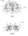
- FIGs. 1-3are various simplified depictions of a cap 100 for use with a dermal tissue lancing device that includes a housing and a lancet moveable with respect to the housing according to an embodiment of the present invention.
- FIGs. 1-3depict cap 100 attached to a component (C) of a dermal tissue lancing device.
- componentsinclude, but are not limited to, a housing of a dermal tissue lancing device, a skin probe of a dermal tissue lancing device, or other suitable component of a dermal tissue lancing device as is known to one skilled in the art.
- Cap 100includes a cap body 102 with an opening 104 therethrough for at least a portion of a lancet L (not shown in FIGs. 1-3 but depicted in FIGs. 7A-7D as discussed below) to pass through.
- Cap body 102has a proximal end 106 and a distal end 108.
- cap body 102includes cap member 110 and retainer 112.
- retainer 112includes four holes 114 therethrough.
- cap bodies employed in embodiments of the present inventioncan take any suitable form.
- Cap member 110includes a rim 116 with a saddle-contoured compression surface 118 that forms a continuous ring for engaging a dermal tissue target site when cap 100 is urged toward such a dermal tissue target site.
- Saddle-contoured compression surface 118 of cap 100is configured such that opposing first portions 120 of rim 116 are located at a higher elevation than opposing second portions 122 of rim 116 (see, for example, FIG. 1).
- An example of a such a saddle-contoured compression surfaceis described in co-pending U.S. Patent Application No. 11/045,542, which is hereby fully incorporated herein by reference.
- any suitable compression surface known to those of skill in the artcan be employed in embodiments of caps for dermal lancing devices according to the present invention, including those described in U.S. Patent Application No. 10/706,166, which is fully incorporated herein by reference.
- Cap 100also includes an attachment mechanism 124 for tiltably attaching cap body 102 to component C of the dermal tissue lancing device.
- attachment mechanism 124is configured such that cap body 102 can tilt to a predetermined limited degree (i.e. to a predetermined maximum angle) relative to the component of the dermal tissue lancing device when distal end 108 of cap body 102 is urged against a dermal tissue target site.
- cap body 102is free to tilt only within a predetermined angle range relative to the component of the dermal tissue lancing device.
- attachment mechanism 124includes four threaded pins 126 and four springs 128, with each of the four springs 128 disposed in a concentric relationship to a different one of the four threaded pins 126 (see, for example, FIG. 3).
- Springs 128can be of any suitable force including, for example, springs with a force in the range of 0.5 to 1.3 kg-f. The range of 0.5 kg-f to 1.3 kg-f has been determined to provide for both comfort and the expression of a biological fluid sample.
- Threaded pins 126are configured for secure engagement with component C as depicted in FIG. 3.
- FIGs. 1-3Although for the purpose of explanation and illustration only, four sets of threaded pins and springs are depicted in FIGs. 1-3 as included in the attachment mechanism, any suitable number of sets of the threaded pins and springs, sufficient to provide tilting necessary for the invention, can be employed. Moreover, the attachment mechanism of caps according to embodiments of the present invention can take a various forms other than the threaded pins and springs depicted in FIGs. 1-3.
- the attachment mechanismcan be a compliant element configured to tiltably attach a cap body to a component C such as, for example, metal flextures (e.g., leaf springs), elastomeric rods, coil springs, gas springs, pins that are slidably attached to component C (in the vertical direction of FIG. 2) and attached to the cap body via a ball joint or swivel, and combinations thereof.
- a component Csuch as, for example, metal flextures (e.g., leaf springs), elastomeric rods, coil springs, gas springs, pins that are slidably attached to component C (in the vertical direction of FIG. 2) and attached to the cap body via a ball joint or swivel, and combinations thereof.
- Springs 128beneficially serve to provide a relatively equal force along saddle-contoured compression surface 118 of cap 100 when cap 100 is urged against a dermal tissue target site.
- the spring force of each of the four springs 128would be identical to one another regardless of the amount of compression of each spring 128.
- spring forcesincrease with compression. Therefore, to minimize any disparity of spring force, it is preferred that springs 128 have a low spring constant.
- the cumulative spring constant of springs 128can be, for example, in the range of 0.05 to 0.15 kg/mm.
- springs 128also beneficially provide for a target site bulge to be formed prior to component C making contact with the dermal tissue target site (see the discussion of FIGs. 7A through 7D below). This is particularly beneficial when component C is a skin probe.
- caps according to the embodiments of the present inventioncan be readily modified for use with caps according to the embodiments of the present invention, including, for example, dermal tissue lancing devices described in the aforementioned U.S. Patent Nos. 5,730,753, 6,045,567 and 6,071,250.
- embodiments of caps according to the present inventioncan be employed with lancing devices that utilize various techniques for expressing a biological fluid sample from a dermal tissue target site including, but not limited to, techniques that employ lancets, hollow needles, solid needles, micro-needles, ultrasonic extraction devices, or thermal extraction devices.
- caps according to embodiments of the present inventioncan be employed with a combined lancing device and integrated meter for testing an analyte (e.g., a meter for testing blood glucose).
- Cap 100comfortably facilitates the flow of a fluid sample (e.g., a blood sample) out of a lanced dermal tissue target site with little or no manipulation (i.e., squeezing and/or milking) of the dermal tissue subsequent to lancing.
- a fluid samplee.g., a blood sample
- saddle-contoured compression surface 118is pressed against a target site (e.g., a dermal tissue target site of a user's finger) such that saddle-contoured compression surface 118 engages (i.e., contacts) the dermal tissue target site and creates a target-site bulge within opening 104.
- Attachment mechanism 124beneficially provides limited axial constraint between retainer 112 and component C such that cap body 102 can tilt relative to component C.
- axial constraintrefers to the degree to which the longitudinal axis of each hole 114 is compelled to remain parallel with the longitudinal axis of each threaded pin 126.
- the axial constraintis "limited" in the sense that longitudinal axes of the threaded pins 126 and holes 114 can deviate by a predetermined amount from parallel such that cap body 102 can tilt relative to component C.
- cap body 102can tilt along an axis that is perpendicular to a sectioning plane along line B-B.
- cap body 102can tilt along various axis other than an axis that is perpendicular to axis B-B.
- Such tiltingis enabled by a predetermined clearance between threaded pins 126 and holes 114 of retainer 112 and the longitudinal dimension (i.e., length) of holes 114. Furthermore, the degree to which cap body 102 can tilt relative to component C is determined by the dimension of said clearance and said length. For a given clearance, the maximum tilt will decrease as the length of holes 114 increases.
- the clearance and length dimension of holes 114can be any suitable dimensions.
- the clearancei.e., distance between a threaded pin and the retainer when a threaded pin is centered in a hole 114) can be 0.1mm and the length of holes 114 can be 1.0mm.
- a clearanceis provided between component C and cap body 102 within opening 104 in order to avoid unwanted interference between cap body 102 and component C during operation of the lancing device. This clearance can be, for example, in the range of 0.25mm to 0.5mm.
- a theoretical plane P through retainer 112forms an angle ⁇ with a theoretical plane P' through component C that corresponds to an untilted position of cap body 102 (see FIG. 5).
- angle ⁇increases, a component of spring force normal (i.e., perpendicular) to the dermal target site decreases while a component of spring force parallel to the dermal tissue target site increases.
- the beneficial creation of a target site bulge and expression of a biological fluid sampleis driven principally by the normal component of spring force. Therefore, it can be desirable to limit the maximum tilt that can be attained by cap body 102.
- Angle ⁇(i.e., the predetermined angle of tilt) can be any suitable angle but is typically in the range between 0 to 25 degrees.
- the tilt enabled by the attachment mechanismprovides for a more uniform application of pressure on a dermal tissue target site, by adapting the angle of the cap to the fit the target site.
- the pressure uniformityimproves the expression of a biological fluid sample and improves user comfort.
- Cap body 102can be formed of any suitable material including, for example, a rigid material such as acrylonitrile butadiene styrene plastic, injection moldable plastic, polystyrene and metallic materials or a relatively resiliently deformable material, including, but not limited, to elastomeric materials, polymeric materials, polyurethane materials, latex materials, silicone materials and any combinations thereof.
- a rigid materialsuch as acrylonitrile butadiene styrene plastic, injection moldable plastic, polystyrene and metallic materials or a relatively resiliently deformable material, including, but not limited, to elastomeric materials, polymeric materials, polyurethane materials, latex materials, silicone materials and any combinations thereof.
- a process 600 for lancing a dermal tissue target siteincludes providing a dermal tissue lancing device with a housing, a lancet that is moveable with respect to the housing, and a cap (see step 610 of FIG. 6).
- the cap of the dermal tissue lancing deviceincludes a cap body with an opening therethrough for at least a portion of the lancet to pass through, a proximal end and a distal end.
- the capalso includes an attachment mechanism for tiltably attaching (either directly or indirectly) the cap body to the housing of the dermal tissue lancing device, whereby the cap body is free to tilt relative to the housing when the distal end of the cap body is urged against a dermal tissue target site.
- the cap of process 600can be, for example, cap 100 of FIGs. 1-5. Therefore, although process 600 can employ any suitable cap, FIGs. 7A through 7D depict cap 100 as described above.
- the distal end of the cap bodyis contacted with a dermal tissue target site such that the distal end engages the dermal tissue target site and the cap body tilts relative to the housing of the dermal tissue lancing device (see FIG. 6 and the sequence of FIGs. 7A and 7B).
- the tilt of the cap bodycan be, for example, in a range between zero degrees and 25 degrees.
- the cap bodyis urged towards the dermal tissue target site such that the cap body applies essentially uniform pressure against the dermal tissue target site, thereby creating a target site bulge, as set forth in step 630 of FIG. 6.
- the cap bodycan be urged until the target site bulge contacts a component C (e.g., a skin probe) of the dermal tissue lancing device as depicted in FIG. 7C (where a dashed line is employed to indicate an edge of component C hidden behind the target site bulge).
- a component Ce.g., a skin probe
- the target site bulgeis lanced with the dermal tissue lancing device.
- a cap for a dermal tissue lancing devicecomprising: a cap body with an opening therethrough for at least a portion of a lancet to pass through; the cap body having: a proximal end; and a distal end an attachment mechanism for tiltably attaching the cap body to the dermal tissue lancing device, whereby the cap body is free to tilt relative to the dermal tissue lancing device when the distal end of the cap body is urged against a dermal tissue target site.
- cap bodyincludes a saddle-contoured compression surface.
- cap bodyincludes a cap member and a retainer and the attachment mechanism attaches the retainer to the dermal tissue lancing device.
- attachment mechanismincludes a compliant member.
- attachment mechanismincludes threaded pins and concentrically arranged springs configured to attach the cap body to the dermal tissue lancing device.
- cap bodyis free to tilt relative to the dermal tissue lancing device due to clearance between the threaded pins and the cap body.
- each of the springshave a force in the range of 0.5 kg-f to 1.3 kg-f.
- attachment mechanismis configured such that the cap body is free to tilt to a within a predetermined angle range relative to the dermal tissue lancing device.
- predetermined angle rangeis the range between zero degrees and twenty-five degrees.
Landscapes
- Health & Medical Sciences (AREA)
- Life Sciences & Earth Sciences (AREA)
- Surgery (AREA)
- Veterinary Medicine (AREA)
- Animal Behavior & Ethology (AREA)
- Public Health (AREA)
- Engineering & Computer Science (AREA)
- Biomedical Technology (AREA)
- Heart & Thoracic Surgery (AREA)
- Medical Informatics (AREA)
- Molecular Biology (AREA)
- General Health & Medical Sciences (AREA)
- Biophysics (AREA)
- Physics & Mathematics (AREA)
- Pathology (AREA)
- Hematology (AREA)
- Dermatology (AREA)
- Nuclear Medicine, Radiotherapy & Molecular Imaging (AREA)
- Pain & Pain Management (AREA)
- Dentistry (AREA)
- Oral & Maxillofacial Surgery (AREA)
- Orthopedic Medicine & Surgery (AREA)
- Measurement Of The Respiration, Hearing Ability, Form, And Blood Characteristics Of Living Organisms (AREA)
Abstract
Description
Claims (10)
- A cap for a dermal tissue lancing device, the cap comprising:a cap body with an opening therethrough for at least a portion of a lancet topass through; the cap body having:a proximal end; anda distal endan attachment mechanism for tiltably attaching the cap body to the dermaltissue lancing device, whereby the cap body is free to tilt relative to the dermal tissuelancing device when the distal end of the cap body is urged against a dermal tissue targetsite.
- The cap of claim 1, wherein the cap body includes a saddle-contouredcompression surface.
- The cap of claim 1 or claim 2, wherein the cap body includes a cap memberand a retainer and the attachment mechanism attaches the retainer to the dermal tissuelancing device.
- The cap of claim 1, claim 2 or claim 3, wherein the attachment mechanismincludes a compliant member.
- The cap of any one of the preceding claims, wherein the attachmentmechanism includes threaded pins and concentrically arranged springs configured to attachthe cap body to the dermal tissue lancing device.
- The cap of claim 5, wherein the cap body is free to tilt relative to the dermaltissue lancing device due to clearance between the threaded pins and the cap body.
- The cap of claim 5 or claim 6, wherein the cumulative spring constant ofthe concentrically arranged springs is in the range of 0.05 to 0.15 kg/mm.
- The cap of claim 5, claim 6 or claim 7, wherein each of the springs have aforce in the range of 0.5 kg-f to 1.3 kg-f.
- The cap of any one of the preceding claims, wherein the attachmentmechanism is configured such that the cap body is free to tilt to a within a predeterminedangle range relative to the dermal tissue lancing device
- The cap of claim 9, wherein the predetermined angle range is the rangebetween zero degrees and twenty-five degrees.
Applications Claiming Priority (6)
| Application Number | Priority Date | Filing Date | Title |
|---|---|---|---|
| US66937 | 1987-06-25 | ||
| US10/825,899US20050234486A1 (en) | 2004-04-16 | 2004-04-16 | Apparatus for extracting bodily fluid |
| US825899 | 2004-04-16 | ||
| US11/066,936US20050234490A1 (en) | 2004-04-16 | 2005-02-25 | Tiltable cap for a dermal tissue lancing device |
| US66936 | 2005-02-25 | ||
| US11/066,937US20050234491A1 (en) | 2004-04-16 | 2005-02-25 | Method for lancing a dermal tissue target site employing a dermal tissue lancing device with a tiltable cap |
Publications (2)
| Publication Number | Publication Date |
|---|---|
| EP1586270A2true EP1586270A2 (en) | 2005-10-19 |
| EP1586270A3 EP1586270A3 (en) | 2006-03-08 |
Family
ID=34940885
Family Applications (1)
| Application Number | Title | Priority Date | Filing Date |
|---|---|---|---|
| EP05252405AWithdrawnEP1586270A3 (en) | 2004-04-16 | 2005-04-18 | Cap for a lancet |
Country Status (10)
| Country | Link |
|---|---|
| US (1) | US20050234491A1 (en) |
| EP (1) | EP1586270A3 (en) |
| JP (1) | JP2005305159A (en) |
| KR (1) | KR20060045769A (en) |
| AU (1) | AU2005201536A1 (en) |
| CA (1) | CA2504455A1 (en) |
| MX (1) | MXPA05004056A (en) |
| NO (1) | NO20051819L (en) |
| SG (1) | SG116620A1 (en) |
| TW (1) | TW200603766A (en) |
Cited By (6)
| Publication number | Priority date | Publication date | Assignee | Title |
|---|---|---|---|---|
| EP2181651A1 (en) | 2008-10-29 | 2010-05-05 | Roche Diagnostics GmbH | Instrument and system for producing a sample of a body liquid and for analysis thereof |
| CN102497814A (en)* | 2009-07-30 | 2012-06-13 | 贝克顿·迪金森公司 | Lancing device with saddle tip |
| WO2013060842A1 (en)* | 2011-10-28 | 2013-05-02 | Materialise N.V. | Guides with pressure points |
| WO2014198700A1 (en)* | 2013-06-13 | 2014-12-18 | Roche Diagnostics Gmbh | Body fluid sampling element |
| US9186104B2 (en) | 2007-04-30 | 2015-11-17 | Roche Diabetes Care, Inc. | Instruments and system for producing a sample of a body fluid and for analysis thereof |
| US9833183B2 (en) | 2008-05-30 | 2017-12-05 | Intuity Medical, Inc. | Body fluid sampling device—sampling site interface |
Families Citing this family (66)
| Publication number | Priority date | Publication date | Assignee | Title |
|---|---|---|---|---|
| US6036924A (en) | 1997-12-04 | 2000-03-14 | Hewlett-Packard Company | Cassette of lancet cartridges for sampling blood |
| US6391005B1 (en) | 1998-03-30 | 2002-05-21 | Agilent Technologies, Inc. | Apparatus and method for penetration with shaft having a sensor for sensing penetration depth |
| US8641644B2 (en) | 2000-11-21 | 2014-02-04 | Sanofi-Aventis Deutschland Gmbh | Blood testing apparatus having a rotatable cartridge with multiple lancing elements and testing means |
| DE10057832C1 (en) | 2000-11-21 | 2002-02-21 | Hartmann Paul Ag | Blood analysis device has syringe mounted in casing, annular mounting carrying needles mounted behind test strip and being swiveled so that needle can be pushed through strip and aperture in casing to take blood sample |
| US7041068B2 (en) | 2001-06-12 | 2006-05-09 | Pelikan Technologies, Inc. | Sampling module device and method |
| US9795747B2 (en) | 2010-06-02 | 2017-10-24 | Sanofi-Aventis Deutschland Gmbh | Methods and apparatus for lancet actuation |
| US7344507B2 (en) | 2002-04-19 | 2008-03-18 | Pelikan Technologies, Inc. | Method and apparatus for lancet actuation |
| US9427532B2 (en) | 2001-06-12 | 2016-08-30 | Sanofi-Aventis Deutschland Gmbh | Tissue penetration device |
| US9226699B2 (en) | 2002-04-19 | 2016-01-05 | Sanofi-Aventis Deutschland Gmbh | Body fluid sampling module with a continuous compression tissue interface surface |
| WO2002101359A2 (en) | 2001-06-12 | 2002-12-19 | Pelikan Technologies, Inc. | Integrated blood sampling analysis system with multi-use sampling module |
| JP4272051B2 (en) | 2001-06-12 | 2009-06-03 | ペリカン テクノロジーズ インコーポレイテッド | Blood sampling apparatus and method |
| US8337419B2 (en) | 2002-04-19 | 2012-12-25 | Sanofi-Aventis Deutschland Gmbh | Tissue penetration device |
| US7981056B2 (en) | 2002-04-19 | 2011-07-19 | Pelikan Technologies, Inc. | Methods and apparatus for lancet actuation |
| EP1395185B1 (en) | 2001-06-12 | 2010-10-27 | Pelikan Technologies Inc. | Electric lancet actuator |
| JP4209767B2 (en) | 2001-06-12 | 2009-01-14 | ペリカン テクノロジーズ インコーポレイテッド | Self-optimized cutting instrument with adaptive means for temporary changes in skin properties |
| AU2002344825A1 (en) | 2001-06-12 | 2002-12-23 | Pelikan Technologies, Inc. | Method and apparatus for improving success rate of blood yield from a fingerstick |
| US7749174B2 (en) | 2001-06-12 | 2010-07-06 | Pelikan Technologies, Inc. | Method and apparatus for lancet launching device intergrated onto a blood-sampling cartridge |
| US7344894B2 (en) | 2001-10-16 | 2008-03-18 | Agilent Technologies, Inc. | Thermal regulation of fluidic samples within a diagnostic cartridge |
| US8702624B2 (en) | 2006-09-29 | 2014-04-22 | Sanofi-Aventis Deutschland Gmbh | Analyte measurement device with a single shot actuator |
| US7892183B2 (en) | 2002-04-19 | 2011-02-22 | Pelikan Technologies, Inc. | Method and apparatus for body fluid sampling and analyte sensing |
| US9795334B2 (en) | 2002-04-19 | 2017-10-24 | Sanofi-Aventis Deutschland Gmbh | Method and apparatus for penetrating tissue |
| US7524293B2 (en) | 2002-04-19 | 2009-04-28 | Pelikan Technologies, Inc. | Method and apparatus for penetrating tissue |
| US7563232B2 (en) | 2002-04-19 | 2009-07-21 | Pelikan Technologies, Inc. | Method and apparatus for penetrating tissue |
| US7229458B2 (en) | 2002-04-19 | 2007-06-12 | Pelikan Technologies, Inc. | Method and apparatus for penetrating tissue |
| US8267870B2 (en) | 2002-04-19 | 2012-09-18 | Sanofi-Aventis Deutschland Gmbh | Method and apparatus for body fluid sampling with hybrid actuation |
| US8221334B2 (en) | 2002-04-19 | 2012-07-17 | Sanofi-Aventis Deutschland Gmbh | Method and apparatus for penetrating tissue |
| US7717863B2 (en) | 2002-04-19 | 2010-05-18 | Pelikan Technologies, Inc. | Method and apparatus for penetrating tissue |
| US7141058B2 (en) | 2002-04-19 | 2006-11-28 | Pelikan Technologies, Inc. | Method and apparatus for a body fluid sampling device using illumination |
| US7491178B2 (en) | 2002-04-19 | 2009-02-17 | Pelikan Technologies, Inc. | Method and apparatus for penetrating tissue |
| US7648468B2 (en) | 2002-04-19 | 2010-01-19 | Pelikon Technologies, Inc. | Method and apparatus for penetrating tissue |
| US9248267B2 (en) | 2002-04-19 | 2016-02-02 | Sanofi-Aventis Deustchland Gmbh | Tissue penetration device |
| US7410468B2 (en) | 2002-04-19 | 2008-08-12 | Pelikan Technologies, Inc. | Method and apparatus for penetrating tissue |
| US7674232B2 (en) | 2002-04-19 | 2010-03-09 | Pelikan Technologies, Inc. | Method and apparatus for penetrating tissue |
| US7582099B2 (en) | 2002-04-19 | 2009-09-01 | Pelikan Technologies, Inc | Method and apparatus for penetrating tissue |
| US7708701B2 (en) | 2002-04-19 | 2010-05-04 | Pelikan Technologies, Inc. | Method and apparatus for a multi-use body fluid sampling device |
| US7374544B2 (en) | 2002-04-19 | 2008-05-20 | Pelikan Technologies, Inc. | Method and apparatus for penetrating tissue |
| US7909778B2 (en) | 2002-04-19 | 2011-03-22 | Pelikan Technologies, Inc. | Method and apparatus for penetrating tissue |
| US7371247B2 (en) | 2002-04-19 | 2008-05-13 | Pelikan Technologies, Inc | Method and apparatus for penetrating tissue |
| US7291117B2 (en) | 2002-04-19 | 2007-11-06 | Pelikan Technologies, Inc. | Method and apparatus for penetrating tissue |
| US7901362B2 (en) | 2002-04-19 | 2011-03-08 | Pelikan Technologies, Inc. | Method and apparatus for penetrating tissue |
| US7547287B2 (en) | 2002-04-19 | 2009-06-16 | Pelikan Technologies, Inc. | Method and apparatus for penetrating tissue |
| US9314194B2 (en) | 2002-04-19 | 2016-04-19 | Sanofi-Aventis Deutschland Gmbh | Tissue penetration device |
| US7232451B2 (en) | 2002-04-19 | 2007-06-19 | Pelikan Technologies, Inc. | Method and apparatus for penetrating tissue |
| US7331931B2 (en) | 2002-04-19 | 2008-02-19 | Pelikan Technologies, Inc. | Method and apparatus for penetrating tissue |
| US7297122B2 (en) | 2002-04-19 | 2007-11-20 | Pelikan Technologies, Inc. | Method and apparatus for penetrating tissue |
| US7976476B2 (en) | 2002-04-19 | 2011-07-12 | Pelikan Technologies, Inc. | Device and method for variable speed lancet |
| US7481776B2 (en) | 2002-04-19 | 2009-01-27 | Pelikan Technologies, Inc. | Method and apparatus for penetrating tissue |
| US8579831B2 (en) | 2002-04-19 | 2013-11-12 | Sanofi-Aventis Deutschland Gmbh | Method and apparatus for penetrating tissue |
| US8784335B2 (en) | 2002-04-19 | 2014-07-22 | Sanofi-Aventis Deutschland Gmbh | Body fluid sampling device with a capacitive sensor |
| US8574895B2 (en) | 2002-12-30 | 2013-11-05 | Sanofi-Aventis Deutschland Gmbh | Method and apparatus using optical techniques to measure analyte levels |
| US7850621B2 (en) | 2003-06-06 | 2010-12-14 | Pelikan Technologies, Inc. | Method and apparatus for body fluid sampling and analyte sensing |
| WO2006001797A1 (en) | 2004-06-14 | 2006-01-05 | Pelikan Technologies, Inc. | Low pain penetrating |
| EP1635700B1 (en) | 2003-06-13 | 2016-03-09 | Sanofi-Aventis Deutschland GmbH | Apparatus for a point of care device |
| US8282576B2 (en) | 2003-09-29 | 2012-10-09 | Sanofi-Aventis Deutschland Gmbh | Method and apparatus for an improved sample capture device |
| EP1680014A4 (en) | 2003-10-14 | 2009-01-21 | Pelikan Technologies Inc | METHOD AND DEVICE FOR A VARIABLE USER INTERFACE |
| US7822454B1 (en) | 2005-01-03 | 2010-10-26 | Pelikan Technologies, Inc. | Fluid sampling device with improved analyte detecting member configuration |
| US8668656B2 (en) | 2003-12-31 | 2014-03-11 | Sanofi-Aventis Deutschland Gmbh | Method and apparatus for improving fluidic flow and sample capture |
| WO2006011062A2 (en) | 2004-05-20 | 2006-02-02 | Albatros Technologies Gmbh & Co. Kg | Printable hydrogel for biosensors |
| WO2005120365A1 (en) | 2004-06-03 | 2005-12-22 | Pelikan Technologies, Inc. | Method and apparatus for a fluid sampling device |
| US8652831B2 (en) | 2004-12-30 | 2014-02-18 | Sanofi-Aventis Deutschland Gmbh | Method and apparatus for analyte measurement test time |
| EP2265324B1 (en) | 2008-04-11 | 2015-01-28 | Sanofi-Aventis Deutschland GmbH | Integrated analyte measurement system |
| US9375169B2 (en) | 2009-01-30 | 2016-06-28 | Sanofi-Aventis Deutschland Gmbh | Cam drive for managing disposable penetrating member actions with a single motor and motor and control system |
| US8965476B2 (en) | 2010-04-16 | 2015-02-24 | Sanofi-Aventis Deutschland Gmbh | Tissue penetration device |
| US8647357B2 (en) | 2011-02-05 | 2014-02-11 | Birch Narrows Development Llc | Lancet device with flexible cover |
| US9237866B2 (en) | 2013-04-29 | 2016-01-19 | Birch Narrows Development, LLC | Blood glucose management |
| JP7104026B2 (en) | 2016-08-24 | 2022-07-20 | ベクトン・ディキンソン・アンド・カンパニー | Device for taking blood samples |
Family Cites Families (21)
| Publication number | Priority date | Publication date | Assignee | Title |
|---|---|---|---|---|
| US3030959A (en)* | 1959-09-04 | 1962-04-24 | Praemeta | Surgical lancet for blood sampling |
| US3208452A (en)* | 1960-09-08 | 1965-09-28 | Panray Parlam Corp | Surface treating device |
| US3338239A (en)* | 1964-10-08 | 1967-08-29 | Mine Safety Appliances Co | Surgical puncturing device |
| US4517978A (en)* | 1983-01-13 | 1985-05-21 | Levin Paul D | Blood sampling instrument |
| US5014718A (en)* | 1988-01-22 | 1991-05-14 | Safety Diagnostics, Inc. | Blood collection and testing method |
| US5026388A (en)* | 1989-09-26 | 1991-06-25 | Ingalz Thomas J | Single-use skin puncture device |
| US5324302A (en)* | 1992-10-13 | 1994-06-28 | Sherwood Medical Company | Lancet with locking cover |
| US5582184A (en)* | 1993-10-13 | 1996-12-10 | Integ Incorporated | Interstitial fluid collection and constituent measurement |
| WO1997004707A1 (en)* | 1995-07-28 | 1997-02-13 | Apls Co., Ltd. | Assembly for adjusting piercing depth of lancet |
| US5879367A (en)* | 1995-09-08 | 1999-03-09 | Integ, Inc. | Enhanced interstitial fluid collection |
| US5951493A (en)* | 1997-05-16 | 1999-09-14 | Mercury Diagnostics, Inc. | Methods and apparatus for expressing body fluid from an incision |
| US6454649B1 (en)* | 1998-10-05 | 2002-09-24 | International Game Technology | Gaming device and method using programmable display switch |
| JP4250699B2 (en)* | 1998-12-16 | 2009-04-08 | アークレイ株式会社 | A lancet device that can safely remove the lancet |
| US6045567A (en)* | 1999-02-23 | 2000-04-04 | Lifescan Inc. | Lancing device causing reduced pain |
| DE10026172A1 (en)* | 2000-05-26 | 2001-11-29 | Roche Diagnostics Gmbh | Body fluid withdrawal system |
| RU2269954C2 (en)* | 2000-06-09 | 2006-02-20 | Дайэбитиз Дайэгностикс, Инк. | Cap for lancet device for punching dermal tissue (versions), cap for lancet device for punching tip of finger, cap for lancet device for punching curvilinear dermal tissue and lancet device for punching dermal tissue |
| EP1328192B1 (en)* | 2001-03-29 | 2011-01-05 | Lifescan Scotland Ltd | Integrated sample testing meter |
| JP2003225227A (en)* | 2002-01-31 | 2003-08-12 | Yamatake Corp | Collection container, collection device and collection method |
| US20030211619A1 (en)* | 2002-05-09 | 2003-11-13 | Lorin Olson | Continuous strip of fluid sampling and testing devices and methods of making, packaging and using the same |
| US7258673B2 (en)* | 2003-06-06 | 2007-08-21 | Lifescan, Inc | Devices, systems and methods for extracting bodily fluid and monitoring an analyte therein |
| US20040249254A1 (en)* | 2003-06-06 | 2004-12-09 | Joel Racchini | Devices, systems and methods for extracting bodily fluid and monitoring an analyte therein |
- 2005
- 2005-02-25USUS11/066,937patent/US20050234491A1/ennot_activeAbandoned
- 2005-04-12CACA002504455Apatent/CA2504455A1/ennot_activeAbandoned
- 2005-04-12AUAU2005201536Apatent/AU2005201536A1/ennot_activeAbandoned
- 2005-04-14NONO20051819Apatent/NO20051819L/ennot_activeApplication Discontinuation
- 2005-04-15TWTW094111919Apatent/TW200603766A/enunknown
- 2005-04-15KRKR1020050031494Apatent/KR20060045769A/ennot_activeWithdrawn
- 2005-04-15SGSG200502328Apatent/SG116620A1/enunknown
- 2005-04-15JPJP2005118615Apatent/JP2005305159A/enactivePending
- 2005-04-15MXMXPA05004056Apatent/MXPA05004056A/enunknown
- 2005-04-18EPEP05252405Apatent/EP1586270A3/ennot_activeWithdrawn
Cited By (14)
| Publication number | Priority date | Publication date | Assignee | Title |
|---|---|---|---|---|
| US9186104B2 (en) | 2007-04-30 | 2015-11-17 | Roche Diabetes Care, Inc. | Instruments and system for producing a sample of a body fluid and for analysis thereof |
| US11045125B2 (en) | 2008-05-30 | 2021-06-29 | Intuity Medical, Inc. | Body fluid sampling device-sampling site interface |
| US9833183B2 (en) | 2008-05-30 | 2017-12-05 | Intuity Medical, Inc. | Body fluid sampling device—sampling site interface |
| EP2181651A1 (en) | 2008-10-29 | 2010-05-05 | Roche Diagnostics GmbH | Instrument and system for producing a sample of a body liquid and for analysis thereof |
| US8926644B2 (en) | 2009-07-30 | 2015-01-06 | Becton, Dickinson And Company | Lancing device having saddle-shaped tip |
| EP2682057A1 (en)* | 2009-07-30 | 2014-01-08 | Becton, Dickinson and Company | Lancing device having saddle-shaped tip |
| CN102497814B (en)* | 2009-07-30 | 2015-01-28 | 贝克顿·迪金森公司 | Lancing device with saddle tip |
| EP2459068A4 (en)* | 2009-07-30 | 2012-11-28 | Becton Dickinson Co | Lancing device having saddle-shaped tip |
| CN102497814A (en)* | 2009-07-30 | 2012-06-13 | 贝克顿·迪金森公司 | Lancing device with saddle tip |
| US8984731B2 (en) | 2011-10-28 | 2015-03-24 | Materialise N.V. | Guides with pressure points |
| WO2013060842A1 (en)* | 2011-10-28 | 2013-05-02 | Materialise N.V. | Guides with pressure points |
| BE1021757B1 (en)* | 2011-10-28 | 2016-01-15 | Materialise N.V. | CONDUCTORS WITH PRESSURE POINTS |
| WO2014198700A1 (en)* | 2013-06-13 | 2014-12-18 | Roche Diagnostics Gmbh | Body fluid sampling element |
| US10660556B2 (en) | 2013-06-13 | 2020-05-26 | Roche Diabetes Care, Inc. | Body fluid sampling element |
Also Published As
| Publication number | Publication date |
|---|---|
| NO20051819D0 (en) | 2005-04-14 |
| MXPA05004056A (en) | 2006-01-18 |
| KR20060045769A (en) | 2006-05-17 |
| AU2005201536A1 (en) | 2005-11-03 |
| TW200603766A (en) | 2006-02-01 |
| EP1586270A3 (en) | 2006-03-08 |
| JP2005305159A (en) | 2005-11-04 |
| US20050234491A1 (en) | 2005-10-20 |
| SG116620A1 (en) | 2005-11-28 |
| CA2504455A1 (en) | 2005-10-16 |
| NO20051819L (en) | 2005-10-17 |
Similar Documents
| Publication | Publication Date | Title |
|---|---|---|
| EP1586270A2 (en) | Cap for a lancet | |
| US20050234490A1 (en) | Tiltable cap for a dermal tissue lancing device | |
| EP1586269A1 (en) | A cap for a dermal tissue lancing device | |
| US20070093864A1 (en) | Method for lancing a dermal tissue target site | |
| EP1527736B1 (en) | Lancing device with a floating probe for control of penetration depth | |
| AU2005201518B2 (en) | Actuation system for a bodily fluid extraction device and associated methods | |
| EP1560517B1 (en) | Cap for a dermal tissue lancing device | |
| US20070060844A1 (en) | Applied pressure sensing cap for a lancing device | |
| US20070032813A1 (en) | Lancing device with pivoting end cap | |
| US20050234486A1 (en) | Apparatus for extracting bodily fluid | |
| JP2003533323A (en) | Body fluid collection system | |
| US20080065130A1 (en) | Elastomeric toroidal ring for blood expression | |
| JP2001523508A (en) | Body fluid sampling device | |
| JP2009524472A (en) | Lancet sensor assembly and meter | |
| HK1081829A (en) | Cap for a lancet | |
| HK1081830A (en) | A cap for a dermal tissue lancing device | |
| JP2006021051A (en) | Puncture apparatus | |
| MXPA05007009A (en) | Apparatus for extracting bodily fluid. | |
| HK1076701B (en) | Cap for a dermal tissue lancing device |
Legal Events
| Date | Code | Title | Description |
|---|---|---|---|
| PUAI | Public reference made under article 153(3) epc to a published international application that has entered the european phase | Free format text:ORIGINAL CODE: 0009012 | |
| AK | Designated contracting states | Kind code of ref document:A2 Designated state(s):AT BE BG CH CY CZ DE DK EE ES FI FR GB GR HU IE IS IT LI LT LU MC NL PL PT RO SE SI SK TR | |
| AX | Request for extension of the european patent | Extension state:AL BA HR LV MK YU | |
| PUAL | Search report despatched | Free format text:ORIGINAL CODE: 0009013 | |
| AK | Designated contracting states | Kind code of ref document:A3 Designated state(s):AT BE BG CH CY CZ DE DK EE ES FI FR GB GR HU IE IS IT LI LT LU MC NL PL PT RO SE SI SK TR | |
| AX | Request for extension of the european patent | Extension state:AL BA HR LV MK YU | |
| REG | Reference to a national code | Ref country code:HK Ref legal event code:DE Ref document number:1081829 Country of ref document:HK | |
| 17P | Request for examination filed | Effective date:20060818 | |
| AKX | Designation fees paid | Designated state(s):AT BE BG CH CY CZ DE DK EE ES FI FR GB GR HU IE IS IT LI LT LU MC NL PL PT RO SE SI SK TR | |
| STAA | Information on the status of an ep patent application or granted ep patent | Free format text:STATUS: THE APPLICATION IS DEEMED TO BE WITHDRAWN | |
| 18D | Application deemed to be withdrawn | Effective date:20091103 | |
| REG | Reference to a national code | Ref country code:HK Ref legal event code:WD Ref document number:1081829 Country of ref document:HK |