EP1584078B1 - Remotely activated, multiple stage alarm system - Google Patents
Remotely activated, multiple stage alarm systemDownload PDFInfo
- Publication number
- EP1584078B1 EP1584078B1EP04700330AEP04700330AEP1584078B1EP 1584078 B1EP1584078 B1EP 1584078B1EP 04700330 AEP04700330 AEP 04700330AEP 04700330 AEP04700330 AEP 04700330AEP 1584078 B1EP1584078 B1EP 1584078B1
- Authority
- EP
- European Patent Office
- Prior art keywords
- communication
- audible
- occupant
- transmitter
- processor
- Prior art date
- Legal status (The legal status is an assumption and is not a legal conclusion. Google has not performed a legal analysis and makes no representation as to the accuracy of the status listed.)
- Expired - Lifetime
Links
- 238000004891communicationMethods0.000claimsabstractdescription161
- 230000004044responseEffects0.000claimsdescription16
- 238000000034methodMethods0.000claimsdescription9
- 230000005540biological transmissionEffects0.000claimsdescription5
- 238000012544monitoring processMethods0.000claimsdescription5
- 239000000779smokeSubstances0.000abstractdescription14
- UGFAIRIUMAVXCW-UHFFFAOYSA-NCarbon monoxideChemical compound[O+]#[C-]UGFAIRIUMAVXCW-UHFFFAOYSA-N0.000abstractdescription10
- 229910002091carbon monoxideInorganic materials0.000abstractdescription10
- 230000000007visual effectEffects0.000abstractdescription9
- 230000001755vocal effectEffects0.000description11
- 230000007246mechanismEffects0.000description9
- 238000012360testing methodMethods0.000description8
- 230000009471actionEffects0.000description7
- 230000003213activating effectEffects0.000description5
- 230000008901benefitEffects0.000description5
- ATUOYWHBWRKTHZ-UHFFFAOYSA-NPropaneChemical compoundCCCATUOYWHBWRKTHZ-UHFFFAOYSA-N0.000description4
- 208000027418Wounds and injuryDiseases0.000description4
- 230000006378damageEffects0.000description4
- 238000001514detection methodMethods0.000description4
- 238000010586diagramMethods0.000description4
- 230000006870functionEffects0.000description4
- 208000014674injuryDiseases0.000description4
- VNWKTOKETHGBQD-UHFFFAOYSA-NmethaneChemical compoundCVNWKTOKETHGBQD-UHFFFAOYSA-N0.000description4
- 206010011878DeafnessDiseases0.000description3
- 241000269400SirenidaeSpecies0.000description3
- 230000010370hearing lossEffects0.000description3
- 231100000888hearing lossToxicity0.000description3
- 208000016354hearing loss diseaseDiseases0.000description3
- 238000011160researchMethods0.000description3
- 230000002618waking effectEffects0.000description3
- 241000282472Canis lupus familiarisSpecies0.000description2
- 241001465754MetazoaSpecies0.000description2
- 238000013459approachMethods0.000description2
- 238000013461designMethods0.000description2
- 239000007789gasSubstances0.000description2
- 235000019645odorNutrition0.000description2
- 230000008569processEffects0.000description2
- 238000012545processingMethods0.000description2
- 239000001294propaneSubstances0.000description2
- 229910052704radonInorganic materials0.000description2
- SYUHGPGVQRZVTB-UHFFFAOYSA-Nradon atomChemical compound[Rn]SYUHGPGVQRZVTB-UHFFFAOYSA-N0.000description2
- 230000035807sensationEffects0.000description2
- 235000019615sensationsNutrition0.000description2
- 244000223760Cinnamomum zeylanicumSpecies0.000description1
- RWSOTUBLDIXVET-UHFFFAOYSA-NDihydrogen sulfideChemical compoundSRWSOTUBLDIXVET-UHFFFAOYSA-N0.000description1
- 241000282326Felis catusSpecies0.000description1
- 208000032041Hearing impairedDiseases0.000description1
- 235000006679Mentha X verticillataNutrition0.000description1
- 235000002899Mentha suaveolensNutrition0.000description1
- 235000001636Mentha x rotundifoliaNutrition0.000description1
- 235000009499Vanilla fragransNutrition0.000description1
- 235000012036Vanilla tahitensisNutrition0.000description1
- 244000263375Vanilla tahitensisSpecies0.000description1
- 239000000443aerosolSubstances0.000description1
- 150000001491aromatic compoundsChemical class0.000description1
- 230000009286beneficial effectEffects0.000description1
- 230000015572biosynthetic processEffects0.000description1
- 230000001413cellular effectEffects0.000description1
- 230000008859changeEffects0.000description1
- 235000017803cinnamonNutrition0.000description1
- 230000001143conditioned effectEffects0.000description1
- 238000001816coolingMethods0.000description1
- 230000007812deficiencyEffects0.000description1
- 230000005484gravityEffects0.000description1
- 229910052736halogenInorganic materials0.000description1
- 150000002367halogensChemical class0.000description1
- 238000010438heat treatmentMethods0.000description1
- 229910000037hydrogen sulfideInorganic materials0.000description1
- 230000000977initiatory effectEffects0.000description1
- 238000009434installationMethods0.000description1
- 238000012423maintenanceMethods0.000description1
- 239000003595mistSubstances0.000description1
- 238000012986modificationMethods0.000description1
- 230000004048modificationEffects0.000description1
- 230000000474nursing effectEffects0.000description1
- 230000003287optical effectEffects0.000description1
- 150000002895organic estersChemical class0.000description1
- 238000003825pressingMethods0.000description1
- 230000008672reprogrammingEffects0.000description1
- 238000003786synthesis reactionMethods0.000description1
- 238000009423ventilationMethods0.000description1
- 229910052724xenonInorganic materials0.000description1
- FHNFHKCVQCLJFQ-UHFFFAOYSA-Nxenon atomChemical compound[Xe]FHNFHKCVQCLJFQ-UHFFFAOYSA-N0.000description1
Images


Classifications
- G—PHYSICS
- G08—SIGNALLING
- G08B—SIGNALLING OR CALLING SYSTEMS; ORDER TELEGRAPHS; ALARM SYSTEMS
- G08B25/00—Alarm systems in which the location of the alarm condition is signalled to a central station, e.g. fire or police telegraphic systems
- G08B25/008—Alarm setting and unsetting, i.e. arming or disarming of the security system
- G—PHYSICS
- G08—SIGNALLING
- G08B—SIGNALLING OR CALLING SYSTEMS; ORDER TELEGRAPHS; ALARM SYSTEMS
- G08B1/00—Systems for signalling characterised solely by the form of transmission of the signal
- G08B1/08—Systems for signalling characterised solely by the form of transmission of the signal using electric transmission ; transformation of alarm signals to electrical signals from a different medium, e.g. transmission of an electric alarm signal upon detection of an audible alarm signal
- G—PHYSICS
- G08—SIGNALLING
- G08B—SIGNALLING OR CALLING SYSTEMS; ORDER TELEGRAPHS; ALARM SYSTEMS
- G08B19/00—Alarms responsive to two or more different undesired or abnormal conditions, e.g. burglary and fire, abnormal temperature and abnormal rate of flow
- G—PHYSICS
- G08—SIGNALLING
- G08B—SIGNALLING OR CALLING SYSTEMS; ORDER TELEGRAPHS; ALARM SYSTEMS
- G08B25/00—Alarm systems in which the location of the alarm condition is signalled to a central station, e.g. fire or police telegraphic systems
- G08B25/009—Signalling of the alarm condition to a substation whose identity is signalled to a central station, e.g. relaying alarm signals in order to extend communication range
Definitions
- the present inventionrelates to an alarm system that cooperates with an external device, and more particularly to an alarm system that transmits at least one of an audible, visual, vibratory, or olfactory communication in response to receiving a signal from an external device identifying the occurrence of an emergency.
- One existing problem in need of a better solutionis how to quickly awaken sleeping occupants in the event of a household emergency.
- One approach to this problemis to increase the volume of noise generated by a traditional alarm.
- thisis not feasible as a very loud noise volume may result in hearing loss to persons who are close to the alarm.
- some recent researchsuggests that a generic alarm tone is not effective in awakening sleeping individuals, particularly children.
- Another approach to the problem of waking sleeping occupantsis to move the detector of the emergency condition into the bedrooms and sleeping chambers, so as to better awaken the sleeping occupants therein.
- the advantage of early warning against fire and/or smoke or carbon monoxide by a unit situated outside of such roomsis lost. By the time an alarm in the bedroom detects smoke, fire, or carbon monoxide, it may be too late for the alarm to be effective in avoiding injury or death.
- U.S. Patent No. 5,867,105describes a wireless alarm system, for use by hearing-impaired persons, wherein a receiving unit is worn on the person and generates a vibration or other perceptible signal.
- Yet another problemis the tendency for a person in an emergency situation to fail to react quickly, properly, and effectively to the circumstances.
- a personmay become panicked, confused, and/or suffer from loss of focus or concentration, and may not clearly analyze the gravity of the situation and/or understand what action should be taken. Thus, it is all too common that precious and critical time is lost, wrong actions are taken, or even no action is taken.
- U.S. Patent No. 5,309,146describes monitoring for the presence of a person in each room of a building so as to efficiently control heating, cooling and ventilation, to control access by maintenance persons, such as a maid, and to indicate to emergency rescue personnel whether a room is vacant or is occupied.
- the present inventionprovides an alarm system for alerting or waking sleeping occupants during an emergency situation.
- the alarm systemreceives a warning signal from an external device, and then a transmitter transmits at least one of an audible communication, a visual communication, or a vibratory communication.
- the alarm systemreceives a warning signal from an external device and determines whether the received warning signal corresponds to a predetermined signal. If the received warning signal corresponds to the predetermined signal, then a transmitter transmits at least one of an audible communication, a visual communication, vibratory communication, or olfactory communication. In either embodiment, the transmitter can transmit a customized, audible communication.
- the term "occupants”includes both persons and animals, including but not limited to dogs and cats.
- structureincludes without limitation, residences, nursing homes, apartments, dormitories, hospitals, hotels, schools, offices, or other buildings inhabited by people and/or animals.
- the communicationmay include both a wakeup message and an instructional message.
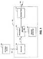
- Figure 1is a block diagram of the preferred embodiment of an alarm system 100 of the present invention.
- Alarm system 100preferably comprises one or more receivers 105, one or more processors 110, one or more transmitters 115, and one or more sensors/detectors 107.
- the processor 110is functionally connected to the receiver 105, the transmitter 115 and the sensor/detector 107.
- memory 120Within or separate from the processor 110 is memory 120.
- Alarm system 100can be a portable safety device such that the receiver 105, processor 110, transmitter 115, and sensor/detector 107 are contained within a single device.
- External device 125is a detector or mechanism capable of sensing the presence of an emergency situation or the existence of a threat of injury or death or danger.
- Examples of such external devices 125include, but are not limited to, fire and smoke detectors/alarms, such as ionization detectors and photoelectric detectors, carbon monoxide (CO) detectors/alarms, earthquake or vibration detectors/alarms, flood detectors/alarms, motion detectors/alarms, burglary detectors/alarms or other entry or breach of security detectors/alarms, etc.
- a well-known external device 125is the common smoke alarm.
- a smoke alarmincludes an emergency condition detector (i.e., circuitry that generates a signal in response to presence of smoke) and an alarm (i.e., circuitry that generates a warning signal 130, such as a tone or a light). Further, a smoke alarm typically includes a simple control feature, such as one or more switches or buttons which allow the user to test, activate, or deactivate the smoke alarm.
- an emergency condition detectori.e., circuitry that generates a signal in response to presence of smoke
- an alarmi.e., circuitry that generates a warning signal 130, such as a tone or a light
- a smoke alarmtypically includes a simple control feature, such as one or more switches or buttons which allow the user to test, activate, or deactivate the smoke alarm.
- the external device 125In response to sensing the emergency situation or threat, the external device 125 emits a warning signal 130 that can be detected by receiver 105.
- the warning signal 130can be audible, such as a loud noise, or visual, such as flashing light, or a tactile sensation, such as a vibration, or an olfactory scent.
- Receiver 105receives the warning signal 130 from the external device 125.
- the receiver 105is adapted to be responsive to signals of the type transmitted by the external device 125.
- the precise structure of the receiver 105depends upon the external device 125 which is to be monitored for determination of the alarm state. For example, the receiver 105 can operate by attempting to "listen" for an alarm tone generated by the external device 125.
- the receiver 105can include a transducer and a bandpass filter tuned to the frequency emitted by the external device 125.
- the receiver 105can also include other functions and/or circuitry, such as a rectifier and lossy integrator coupled to a comparator, which determines whether the bandpass filter is passing a signal of sufficient strength to justify the inference that the external device 125 is emitting an audible warning signal 130. This may be done by hardware, software, or a combination thereof.
- receiver 105may comprise one or more acoustic transducers, such as for example, microphones, or, if the signal 130 is a flashing light, receiver 105 may comprise one or more photodetectors or phototransistors. If the signal 130 is vibratory, receiver 105 may comprise one or more motion or seismic detectors. Seismic detectors, such as, for example, the one disclosed in U.S. Patent No. 4,358,757 to Perini, are well known in the art. If the signal 130 is a scent or smell, receiver 105 may comprise one or more, olfactory or smell sensors. Smell sensors are well known in the art, and one example is disclosed in U.S. Patent No.
- the receiver 105may also comprise amplifiers, threshold detectors or comparators, filters, and/or integrators.
- the receiver 105converts the signal 130 into a signal 133 which is in a form or format which can be used by or operated upon by the processor 110. This may be done by hardware, software, or a combination thereof.
- Communication of signals 130 between the receiver 105 and the external device 125can be by any desired means operative in and appropriate to the particular environment. Examples include, but are not limited to, wire or cable, wireless, sound, and light, including visible, laser, ultraviolet and infrared. Additionally, more than one receiver 105 can be used so as to detect one or more of a sound, light, motion, or scent.
- receivers 105can be placed throughout a structure so as to be more responsive to the signal 130.
- one or more external device emergency condition detectors 125can be combined with one or more receivers 105.
- External device emergency condition detectors 125include detectors of smoke, heat, carbon monoxide, radon gas, methane, propane, seismic vibrations, or other dangerous conditions.
- processing of signalsis performed by the receiver 105, it will be appreciated that processing may be performed by processor 110, by one or more analog or digital circuits, software, or any desired combination thereof.
- alarm system 100can be networked to an external device 125 and/or to one or more additional alarm systems 100 such that the alarm system 100 is automatically activated when the external device 125 or the additional system 100 is activated.
- information regarding which alarm system 100 has been activated by a signal 130 from one or more external devices 125can be communicated to remote alarm systems 100, triggering the transmission of additional communications 135.
- information such as which room of the building contains the triggering alarm system 100can be communicated to remote alarm system, thereby initiating appropriate communications 135, such as "Warning - system activated in Bobby's bedroom.”
- alarm system 100in combination with a motion detector 107 (Fig.
- alarm system 100can communicate information as to whether the occupant of the room is moving. Such communications provide the occupants and others, such as emergency rescue personnel, with information critical for a faster and more focused response, thereby increasing the chance of saving lives and avoiding injury to occupants in need of assistance.
- the alarm system 100can also activate other devices. For example, alarm system 100 can activate a telephone or cellular phone that is programmed to call an emergency service and/or the alarm system 100 can activate a sprinkler system.
- Processor 110receives the signal 133 from the receiver 105.
- Processor 110is preferably a microprocessor and compares the signal 133 to a predetermined signal stored in its memory 120. If the received warning signal 130, as represented by signal 133, corresponds to the predetermined signal, the processor 110 causes the transmitter 115 to transmit a communication 135. Additionally, a warning signal 130 can be stored by the processor 110 into its memory 120 to become the predetermined signal.
- the processor 110once the processor 110 receives signal 133 from receiver 105, the processor 110 causes the transmitter 115 to transmit a communication 135 without comparing the received signal 130 to the predetermined signal. For example, signal 130 can be tested against a decibel threshold, and if the noise is loud enough, then signal 133 causes processor 110 to transmit communication 135. Moreover, communications 135 can be customized and stored by processor 110 into its memory 120.
- the alarm system 100can be located in a region that is remote from the external device 125 as long as the receiver 105 can detect the signal 130.
- the alarm system 100can be located in a bedroom, while the external device 125 is located in a kitchen.
- the alarm system 100located in a bedroom, transmits a communication 135 in response to the external device 125 identifying an emergency condition in the kitchen and transmitting a warning signal 130.
- an occupant of the bedroomis alerted to the occurrence of an emergency in the kitchen, such as a fire, before the emergency condition migrates through the house and to the bedroom. This provides additional time for the occupant to escape or take other action, such as determining the nature or cause of the emergency, assisting others, calling for assistance, alerting governmental authorities, etc.
- the warning signal 130can be a preprogrammed, predetermined signal which external device 125 emits or can be controlled to emit.
- the warning signal 130can be learned by the processor 110, such that the user inputs a warning signal 130 from the external device 125 to be stored as the predetermined signal in the memory 120.
- a transmitter 115can transmit one or more audible, visual, vibratory, or olfactory communications 135.
- Transmitter 115can be a sound generator, such as a speaker or conventional buzzer, a flashing light generator, a vibration generator, or an olfactory scent generator. Additionally, several different transmitters 115 can be used in combination to provide redundancy or a plurality of communication types.
- communications 135can be one or more of an audible, visual, vibratory, or olfactory communication.
- Audible communications 135can include loud noises, such as names, commands, sirens, tones, and other audible communications.
- Visual communications 135can include a visible light such as a bright flashing light, such as can be produced by use of a strobe light, halogen light, or xenon discharge light.
- Olfactory communications 135can be any distinctive or pungent odor, such as cinnamon, mint, vanilla, hydrogen sulfide, organic esters, other synthesized aromatic compounds, or other pungent or distinctive, preferably non-flammable, odors, released in a suitable manner, such as a mist or an aerosol.
- the alarm system 100would include a mechanism to generate vibratory communications 135.
- the alarm system 100may be attached to an object, such as a bed.
- the vibratory communications 135can be generated directly via mechanical connection between the alarm system 100 and the article to which it is attached, or indirectly via sound or vibration generated by the alarm system 100 and transmitted to the article via indirect contact with, or close association to, the object.
- Communications 135can be preprogrammed into the memory 120 of the processor 110 such that generic sounds, tones, sirens, sequences of flashing lights, vibrations, and/or scents can be transmitted. Moreover, several different communications 135 can be used in combination with each other. For example, loud noises, flashing lights, and vibrations can be transmitted concurrently or sequentially. Loud noises, such as those of barking dogs, are effective both to awaken people and to gain the attention of household pets. In one embodiment, communication 135 is a non-verbal tone or sound, such as those standard and commonly used in smoke and carbon monoxide detectors.
- communication 135is an audible customized communication 135 stored in memory 120.
- the audible customized communication 135can be a prerecorded vocal message or a synthesized verbal message.
- the audible customized communication 135can be recorded in a voice familiar to the occupants.
- a usercan record the name of an occupant of the house (e.g., a child's name, a spouse's name, a parent's name, or a pet's name) and/or a command (e.g., a command to evacuate the house or to go to the front door) into memory 120.
- the memory 120can store more than one vocalized message.
- the memory device 120can store a mother's and a father's message to a child.
- an audible communication 135can iteratively instruct a child first in the voice of the child's mother and then in the voice of the child's father ("Reid, wake up ( mother's voice )... Reid, wake up ( father's voice )... ").
- alarm system 100can alternately transmit a person's name followed by one or more tones, sirens, or commands in patterns such as the following: (“Sarah ... wake up and leave the house ... Sarah ... wake up and leave the house”); (“Wake up, Sarah ... [TONE] ... Wake up, Sarah [TONE]); (“Sarah... [SIREN]... Sarah...[SIREN]), ("[SIREN]... [TONE]... [SIREN]... [TONE]”) ("[SIREN #1]... [SIREN #2]... [TONE]... [SIREN #1]”), etc.
- the processor 110can individually select the volume at which each of the stored communications 135, or parts of them, are transmitted. For example, it may be preferable to steadily increase the volume until the maximum volume is reached, or to alternate between medium and high volumes, or to say one part of the message at a higher volume, such as the person's name, followed by another part of the message at a lesser volume, such as the instructions on what to do.
- processor 110can cause one or more of the transmitters 115 to transmit a different communication 135 than another transmitter 115.
- the communication 135may be a standard or customized communication which is stored in the transmitter 115.
- the processor 110merely instructs the transmitter 115 to begin transmitting its own stored communication message.
- a transmitter 115may have more than one stored communication message so the processor could instruct the transmitter 115 which message or messages to use, or the transmitter 115 could use one or more of them, sequentially or in random order.
- the alarm system 100may have one or more sensors/detectors 107 as shown in more detail in Figures 3, 4, and 5.
- the systemmay include one or more motion sensors/detectors 107, as more particularly shown in Figure 5.
- Sensors/detectors 107may include detectors of motion, smoke, heat, carbon monoxide, radon gas, methane, propane, seismic vibrations, or other dangerous conditions. If an emergency condition is detected, or an external device sounds an alarm, then if a motion detector 107 is present, the processor 110 can be programmed to cause transmitter 115 to transmit a first communication 135 until motion is detected, thereby indicating that the occupant has awoken, and thereafter transmit a second communication 135.
- the alarm system 100can repeatedly vocalize a first audible communication 135 to awaken ("Sarah, wake up... Sarah, wake up"). Upon detecting motion, the alarm system 100 can vocalize a second audible communication 135, such as instructing the occupant to leave the dwelling.
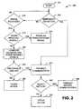
- FIG. 2is a flow chart illustration of a method 200 of operating an alarm system 100 according to a preferred embodiment of the present invention. It will be appreciated that the processor 110 performs or controls most of the steps described herein.
- the alarm system 100reacts when a receiver 105 receives a signal or an emergency condition is detected.
- step 201the system determines 205 whether a sensor/detector 107 has detected an emergency condition. If so, the system proceeds to step 235. If not, the system proceeds to decision 210. Decision 210 determines whether a signal, such as warning signal 130, has been received from an external device, such as external device 125. If not, the system returns to step 201. If so, the system proceeds to step 215.
- a signalsuch as warning signal 130
- Step 215determines whether to learn the received signal. If the processor 110 is in a programmable mode wherein the user has inputted that the received signal is to be learned by the processor 110, the processor 110 at step 220 then stores the received signal as the predetermined signal and then returns to step 205.
- Step 230determines whether the received signal is similar to the predetermined signal. If at decision 230 the received signal differs from the predetermined signal, then some other action is performed 255, which may be just returning to step 205. If the received signal is comparable to the predetermined signal, then the processor 110 proceeds to step 235.
- the step 225may determine and compare a plurality of factors, such as frequency, frequency variation, amplitude variation, amplitude within or outside of a certain passband, duration, pulse duration, pulse repetition rate, duty cycle, etc. However, the step 225 may also operate very simply, such as determining the presence of a signal having at least a predetermined amplitude.
- the process of comparingis preferably performed by processor 110, it will be appreciated that some or all of that process may be performed by one or more analog or digital circuits.
- the processor 110causes the transmitter 115 to transmit a communication 135.
- the alarm system 100may optionally detect motion at step 240. If motion is detected, a second communication 135 can be transmitted at step 245. If motion is not detected, other action is performed at step 250, which action may be that the alarm system 100 continues to transmit a first communication 135 until motion is detected. Or, the alarm system 100 can wait a predetermined amount of time before transmitting a second communication. The alarm system 100 can also increase the volume of an audible communication 135, begin or continue flashing lights, begin or continue vibratory alarms, etc., until motion is detected. It will be appreciated that motion detection may be performed at a different stage.
- step 235it could be performed before step 235 and determine the communication 135 to be used at step 235.
- the first communication 135may be an instruction to leave the premises, rather than just being an attempt to alert the occupant to the emergency condition.
- the alarm system 100provides features and benefits not available in the prior art: detection of an alarm signal 130 from a remote sensor or alarm 125, multiple alarm signal types, and multiple alarm signal stages, e.g., before and after motion is detected. These features and benefits are independent, but not mutually exclusive, and can be combined as desired.
- Figures 3, 4 and 5depict other exemplary alarm systems 100.
- the alarm system 100preferably includes one or more receivers 105, one or more emergency condition and/or motion sensors/detectors 107.
- a sensor/detector 107performs the same sensing/detection functions as an external device 125 but is part of the alarm system 100 so it may, or may not, also provide an external alarm signal 130.
- the alarm system 100preferably includes user input devices 330, such as switches, buttons, etc., that allow a user to control the operation of the alarm system 100, such as activating or deactivating one or more of the receivers 105, sensors/detectors 107, and transmitters 115.
- User input devices 330can also include data or communication ports such that other devices, such as personal and portable computers and handheld computing devices, can connect to the alarm system 100 so as to input communications 135 or commands.
- a usercan connect the user input device 330 to a personal computer, and then use the keyboard to type in an occupant's name and instructions to exit the structure, which can then be synthesized into an audible communication 135, as described herein.
- the control station 310comprises a processor 110 and memory 120.
- the user input devices 330may be part of, or may be separate from, the control station 310. Additionally, the user input devices 330 can connect to the control station 310, or the user input devices 330 can connect directly to the alarm system 100.
- the receivers 105, sensors/detectors 107, and transmitters 115can be dispersed throughout a structure to ensure the desired coverage throughout the structure.
- the receivers 105operate as previously described and communicate with the control station 310.
- the detectors 107operate in well-known manners and also communicate with the control station 310.
- the control station 310commands one or more of the transmitters 115 to transmit a communication 135.
- any component 105, 115 or 107can communicate directly with any other component 105, 115 or 107.
- the alarm system 100can be embodied as a transmitter 115 that is integrated into the external device 125.
- the receiver 105 within the alarm system 100includes communication and control circuitry that permits the alarm system 100 to receive data indicating the occurrence of an emergency.
- the receiver 105can include a network card.
- the control station 310communicates via a communications link 320 with the receivers 105, sensors/detectors 107, transmitters 115, and user input devices 330.
- the communication link 320may be wired and/or wireless, as desired and appropriate under the particular circumstances.
- Figure 3depicts an alarm system 100 which has a communications link 320 wherein all of the devices are on a common link, such as a common data bus or data channel.
- Figure 4depicts an alarm system 100 which has a plurality of communications links 320A-320G, wherein each device is on a separate link, such as an independent data bus or data channel.
- FIG. 5depicts a block diagram of another exemplary alarm system 100.
- the alarm system 100includes a processor 110, such as a microprocessor 110, which communicates via a communications link 320, which may be a data bus, with a volatile memory device 120A, such as a random access memory (RAM), and a non-volatile memory device 120B, such as a read only memory (ROM), flash card memory, rewritable CD, DVD or other disk, floppy disk, hard drive, etc.
- RAMrandom access memory
- ROMread only memory
- the read only memory device 120Bstores firmware used for running the device.
- the firmwarecan be transferred from the non-volatile memory device 120B to the volatile memory device 120A at power-up, or upon reset, etc.
- the memory 120can be used to store a digitized representation of one or more communications 135. These digitized sounds can be restored to analog form via a digital-to-analog converter 435.
- the analog signal yielded therefromcan be amplified or otherwise conditioned by an amplifier circuit 440.
- the signalis transduced to an audible form 135 via a transmitter 115, such as a speaker.
- the digitized representation of soundscan be pre-programmed into the memory 120.
- the memory 120can store a set of digitized vocalization of common names, commands, or messages.
- the alarm system 100may include a transducer 450, such as a microphone 450, coupled to an analog-to-digital converter 455, which transducer and associated circuitry may be the same as, part of, or independent of, a receiver 105.
- the analoa-to-digital converter 455can communicate with the processor 110 via the communications link 320.
- a user of the alarm system 100can recite a message, such as the name of an occupant of the house (e.g., a child's name, a spouse's name, an elderly parent's name, or a pet's name) or a command (e.g., a command to evacuate the house) into the microphone 450.
- the microphone 450converts the vocalization into an analog electric signal, which is converted to a digital signal by the analog-to-digital converter 455.
- the microprocessor 110receives the digitized signal from the analog-to-digital converter 455 and writes the signal into the memory 120.
- the digitized vocalizationscan be stored in a cache memory located on-board the microprocessor 110 and can be stored later in a flash memory device 120B.
- the processor 110can optionally and individually select the volume at which each of the stored audible communications 135 is emitted.
- the amplifier 440can be controlled by a gain selection signal that is generated by the processor 110.
- the microprocessorcan be programmed to permit a user to determine the volume at which each of the stored audible communications 135 is set.
- the alarm system 100transmits a first audible communication 135 followed by a second audible communication 135.
- the first audible communication 135can be a name of an occupant and a command to awaken
- the second audible communication 135can be a command to evacuate.
- Flynnwake up... leave the house and meet in our special place
- the volume of each audible communication 135can be individually selected by the processor 110.
- the processor 110can be programmed to play the first audible communication 135 (i.e., the vocalization of the occupant's name and the command to awaken) at a relatively high volume, while the second audible communication 135 (i.e., the command to evacuate) at a lesser volume.
- the first audible communication 135i.e., the vocalization of the occupant's name and the command to awaken
- the second audible communication 135i.e., the command to evacuate
- the alarm system 100may include a motion sensor/detector 107 in communication with the processor 110.
- the processor 110can be programmed to cause transmitter 115 to transmit a first communication 135 until motion is detected by the motion sensor/detector 107 (indicating that the occupant has awoken), and thereafter transmit a second communication 135.
- the alarm system 100can repeatedly vocalize a first audible communication 135 to awaken ("Sarah, wake up... Sarah, wake up").
- the alarm system 100can vocalize a second audible communication 135, such as instructing the occupant to leave the dwelling.
- the alarm system 100can lack a receiver 105, but instead can possess only an emergency condition sensor/detector 107.
- the processor 110can be programmed to transmit any of the communications 135 described herein in response to detection of an emergency condition.
- the alarm system 100can use two transmitters 115 to transmit an audible communication 135 simultaneously with transmitting a visual communication 135 and/or vibratory communication 135.
- the alarm system 100can both emit an audible communication 135 and flash a strobe light or shake a bed.
- the memory 120can store elemental vocal sounds which can be combined to form words.
- a usercan input vocal communications in the form of data, such as a typed sentence, into or via the user input device 330.
- the microprocessor 110can then generate a complete vocal sequence from the elemental vocal sounds, so as to create a synthesized audible communication 135.
- the synthesized audible communication 135can be stored in the memory 120 for later replay (as when an emergency state has been detected).
- the alarm system 100comprises a mechanism for the user to record a message, and a mechanism for the alarm system 100 to play back the recorded message when the alarm system 100 is activated upon sensing that a remote detector has detected an emergency condition.
- the recording and playback aspectcan be analog, for example a magnetic tape such as a cassette tape mechanism, or it can be digital.
- a usercan use an input device such as a keyboard, handheld computing device equipped with an infrared transmitter, or a microphone to record a sentence into memory 120 via the receiver 105 and processor 110.
- the sentence typed inmay be "Reid, wake up.”
- a complete vocal patternis constructed from the elemental vocal patterns stored in the memory 120, and is stored in its complete form.
- the alarm system 100can include any synthesizer unit known in the art.
- the user inputmay be directly into the transmitter 115, rather than into the memory 120 or the processor 110, so that each transmitter 115 stores and recalls the communication with respect to its own memory (not shown).
- the alarm system 100is programmed to require an access code to permit reprogramming of communications 135 or warning signals 130. This reduces the likelihood that a child or some other person will change the settings, programming, or messages.
- the access codecan be a numeric sequence, a sequence of button pushes, or any other suitably complex set of inputs to the processor 110.
- vocal communications 135can be combined with an embodiment including a motion sensor/detector 107 and an emergency condition sensor/detector 107.
- a plurality of audible communications 135 and/or other communications 135can be stored in memory 120, any of which can be transmitted at any volume selected by the microprocessor 110.
- any of the integrated circuitsi.e., memory devices 120A and 120B, converters 435 and 455, and processor 110
- the alarm system 100can be designed to implement the functionality described herein with an application specific integrated circuit, which uses logic to implement such functionality rather than software/firmware.
- communications 135can be stored on any storage medium, including but not limited to, read only memory chips, random access memory chips, flash memory devices, magnetic storage media, optical storage media, or magneto-optical storage media.
- the alarm system 100can be wired into household electrical service, the alarm system 100 can optionally be powered by batteries. Still further, the alarm system 100 can be capable of using either, or both household electrical service and battery power.
- the alarm system 100can further comprise a test mechanism.
- the test mechanismcomprises standard circuitry for device system testing, which is routine to one skilled in the art, along with an interface for a person or machine to activate the test system. Examples of mechanisms for activating the test system include but are not limited to mechanical switches, photoelectric sensors, infra red sensors, motion sensors, sound sensors and digital communications, including wired or wireless communications, activating the alarm function of the external device 125 by pressing its test button, etc. Alternately, the test mechanism can be activated remotely, as from a remote control device or by activating the external device 125.
- the alarm system 100may be a portable, self contained unit. This allows use when traveling, such as in a hotel or motel, or when a guest in another's home.
- the systemmay be placed on the floor near the door so as to detect an alarm in the hallway which may otherwise be too faint to wake the occupant. In such a case, the system may simply listen for a high-pitched tone having a least a certain amplitude and duration, as it may not be practical to active the hotel alarm system for purposes of storing a predetermined signal particular to the hotel alarms in use.
Landscapes
- Physics & Mathematics (AREA)
- General Physics & Mathematics (AREA)
- Business, Economics & Management (AREA)
- Emergency Management (AREA)
- Engineering & Computer Science (AREA)
- Computer Security & Cryptography (AREA)
- Alarm Systems (AREA)
- Electromechanical Clocks (AREA)
- Emergency Alarm Devices (AREA)
Abstract
Description
- This application claims the priority of
U.S. Provisional Patent Application No. 60/441,114 filed January 17, 2003 U.S. Non-Provisional Patent Application No. 10/695,590 filed October 28, 2003 - The present invention relates to an alarm system that cooperates with an external device, and more particularly to an alarm system that transmits at least one of an audible, visual, vibratory, or olfactory communication in response to receiving a signal from an external device identifying the occurrence of an emergency.
- Fire, smoke, carbon monoxide, and other home hazards pose significant and ongoing risks to families, individuals, and pets in households across the country and around the world. There is a continuing need to provide more effective safety devices and methods to reduce injuries and death.
- One existing problem in need of a better solution is how to quickly awaken sleeping occupants in the event of a household emergency. One approach to this problem is to increase the volume of noise generated by a traditional alarm. However, this is not feasible as a very loud noise volume may result in hearing loss to persons who are close to the alarm. Moreover, irrespective of the volume of the alarm, some recent research suggests that a generic alarm tone is not effective in awakening sleeping individuals, particularly children.
- Another approach to the problem of waking sleeping occupants is to move the detector of the emergency condition into the bedrooms and sleeping chambers, so as to better awaken the sleeping occupants therein. However, in this arrangement the advantage of early warning against fire and/or smoke or carbon monoxide by a unit situated outside of such rooms is lost. By the time an alarm in the bedroom detects smoke, fire, or carbon monoxide, it may be too late for the alarm to be effective in avoiding injury or death.
- An additional problem exists for people with selective hearing loss. Presently, emergency alarms in the home employ a single frequency alarm or tonal buzzer, which may not adequately be heard by persons having a selective hearing loss or deficiency in that particular frequency range.
U.S. Patent No. 5,867,105 describes a wireless alarm system, for use by hearing-impaired persons, wherein a receiving unit is worn on the person and generates a vibration or other perceptible signal.- Yet another problem is the tendency for a person in an emergency situation to fail to react quickly, properly, and effectively to the circumstances. A person may become panicked, confused, and/or suffer from loss of focus or concentration, and may not clearly analyze the gravity of the situation and/or understand what action should be taken. Thus, it is all too common that precious and critical time is lost, wrong actions are taken, or even no action is taken.
U.S. Patent No. 5,309,146 describes monitoring for the presence of a person in each room of a building so as to efficiently control heating, cooling and ventilation, to control access by maintenance persons, such as a maid, and to indicate to emergency rescue personnel whether a room is vacant or is occupied.- Finally, many families and individuals will benefit from an easy-to-use safety device. Safety devices that children can understand and readily respond to are more likely to be used by families. This in turn may cause families to discuss safety with household members, make a household safety plan, and practice emergency procedures,
- Recent research only now identifies the problem of the inability of standard smoke detector alarms to awaken sleeping individuals, especially children. It is reasonable to assume that this problem extends to other types of emergency condition detectors, including carbon monoxide detectors and burglary alarms. Current research indicates that recitation of a person's name during sleep may be a more effective means by which to awaken that person, especially a child who is sound asleep. Additionally, this may be particularly true if the person's name is spoken by an individual familiar to the sleeping person (e.g., the sound of a parent calling the child's name).
- The present invention provides an alarm system for alerting or waking sleeping occupants during an emergency situation. The alarm system receives a warning signal from an external device, and then a transmitter transmits at least one of an audible communication, a visual communication, or a vibratory communication. In another embodiment, the alarm system receives a warning signal from an external device and determines whether the received warning signal corresponds to a predetermined signal. If the received warning signal corresponds to the predetermined signal, then a transmitter transmits at least one of an audible communication, a visual communication, vibratory communication, or olfactory communication. In either embodiment, the transmitter can transmit a customized, audible communication.
- Accordingly, it is an object of the present invention to provide a more effective means of alerting or waking occupants of a structure during an emergency. It should be noted that the term "occupants" includes both persons and animals, including but not limited to dogs and cats. It should also be noted that the term "structure" includes without limitation, residences, nursing homes, apartments, dormitories, hospitals, hotels, schools, offices, or other buildings inhabited by people and/or animals.
- It is another object of the present invention to provide an alarm system located in close proximity to an occupant, who may be sleeping, but which alarm system is activated by an external device remote to the occupant.
- It is yet another object of the present invention to provide an alarm system that transmits a customized communication in response to receiving a warning signal from an external device.
- Further, in situations where it is desirable or necessary to provide the occupant with instructions, the communication may include both a wakeup message and an instructional message. However, in some cases, it may be more beneficial to first wake the occupant, and then provide the occupant with a separate instructional message once it has been determined that the occupant has been awakened. For example, it may be more effective to repeat the child's name while flashing a light until the child has been awakened, and then eliminate the flashing light and provide an instructional message on what to do. Thus, it is yet another object of the present invention to provide a multiple-stage communication.
- Other objects, features, and advantages of the present invention will become apparent upon reading the following description of the preferred embodiment, when taken in conjunction with the drawings and claims.
- Figure 1 is a block diagram of the preferred embodiment of the present invention.
- Figure 2 is a flow chart illustrating a method of remotely triggering an alarm system in accordance with a preferred embodiment of the present invention.
- Figures 3, 4 and 5 are block diagrams of exemplary alarm systems.
- Turning now to the drawings, in which like numerals represent like components throughout the several figures, Figure 1 is a block diagram of the preferred embodiment of an
alarm system 100 of the present invention. Alarm system 100 preferably comprises one ormore receivers 105, one ormore processors 110, one ormore transmitters 115, and one or more sensors/detectors 107. Theprocessor 110 is functionally connected to thereceiver 105, thetransmitter 115 and the sensor/detector 107. Within or separate from theprocessor 110 ismemory 120.Alarm system 100 can be a portable safety device such that thereceiver 105,processor 110,transmitter 115, and sensor/detector 107 are contained within a single device.External device 125 is a detector or mechanism capable of sensing the presence of an emergency situation or the existence of a threat of injury or death or danger. Examples of suchexternal devices 125 include, but are not limited to, fire and smoke detectors/alarms, such as ionization detectors and photoelectric detectors, carbon monoxide (CO) detectors/alarms, earthquake or vibration detectors/alarms, flood detectors/alarms, motion detectors/alarms, burglary detectors/alarms or other entry or breach of security detectors/alarms, etc. For example, a well-knownexternal device 125 is the common smoke alarm. A smoke alarm includes an emergency condition detector (i.e., circuitry that generates a signal in response to presence of smoke) and an alarm (i.e., circuitry that generates awarning signal 130, such as a tone or a light). Further, a smoke alarm typically includes a simple control feature, such as one or more switches or buttons which allow the user to test, activate, or deactivate the smoke alarm.- In response to sensing the emergency situation or threat, the
external device 125 emits awarning signal 130 that can be detected byreceiver 105. Thewarning signal 130 can be audible, such as a loud noise, or visual, such as flashing light, or a tactile sensation, such as a vibration, or an olfactory scent. Receiver 105 receives thewarning signal 130 from theexternal device 125. Thereceiver 105 is adapted to be responsive to signals of the type transmitted by theexternal device 125. The precise structure of thereceiver 105 depends upon theexternal device 125 which is to be monitored for determination of the alarm state. For example, thereceiver 105 can operate by attempting to "listen" for an alarm tone generated by theexternal device 125. In this case, thereceiver 105 can include a transducer and a bandpass filter tuned to the frequency emitted by theexternal device 125. Thereceiver 105 can also include other functions and/or circuitry, such as a rectifier and lossy integrator coupled to a comparator, which determines whether the bandpass filter is passing a signal of sufficient strength to justify the inference that theexternal device 125 is emitting anaudible warning signal 130. This may be done by hardware, software, or a combination thereof.- For example, if the
signal 130 is an audible alarm,receiver 105 may comprise one or more acoustic transducers, such as for example, microphones, or, if thesignal 130 is a flashing light,receiver 105 may comprise one or more photodetectors or phototransistors. If thesignal 130 is vibratory,receiver 105 may comprise one or more motion or seismic detectors. Seismic detectors, such as, for example, the one disclosed inU.S. Patent No. 4,358,757 to Perini, are well known in the art. If thesignal 130 is a scent or smell,receiver 105 may comprise one or more, olfactory or smell sensors. Smell sensors are well known in the art, and one example is disclosed inU.S. Patent No. 5,047,214 to Fukui et al . Thereceiver 105 may also comprise amplifiers, threshold detectors or comparators, filters, and/or integrators. Thereceiver 105 converts thesignal 130 into asignal 133 which is in a form or format which can be used by or operated upon by theprocessor 110. This may be done by hardware, software, or a combination thereof. Communication ofsignals 130 between thereceiver 105 and theexternal device 125 can be by any desired means operative in and appropriate to the particular environment. Examples include, but are not limited to, wire or cable, wireless, sound, and light, including visible, laser, ultraviolet and infrared. Additionally, more than onereceiver 105 can be used so as to detect one or more of a sound, light, motion, or scent. For example,several receivers 105 can be placed throughout a structure so as to be more responsive to thesignal 130. Moreover, one or more external deviceemergency condition detectors 125 can be combined with one ormore receivers 105. External deviceemergency condition detectors 125 include detectors of smoke, heat, carbon monoxide, radon gas, methane, propane, seismic vibrations, or other dangerous conditions. Once areceiver 105 receives thewarning signal 130, thereceiver 105 passes thewarning signal 130 to theprocessor 110 as thesignal 133. - Although it is preferred that processing of signals is performed by the
receiver 105, it will be appreciated that processing may be performed byprocessor 110, by one or more analog or digital circuits, software, or any desired combination thereof. - Alternatively,
alarm system 100 can be networked to anexternal device 125 and/or to one or moreadditional alarm systems 100 such that thealarm system 100 is automatically activated when theexternal device 125 or theadditional system 100 is activated. When a plurality ofalarm systems 100 are networked, information regarding whichalarm system 100 has been activated by asignal 130 from one or moreexternal devices 125 can be communicated toremote alarm systems 100, triggering the transmission ofadditional communications 135. For example, information such as which room of the building contains the triggeringalarm system 100 can be communicated to remote alarm system, thereby initiatingappropriate communications 135, such as "Warning - system activated in Bobby's bedroom." Additionally,alarm system 100, in combination with a motion detector 107 (Fig. 3), can communicate information as to whether the occupant of the room is moving. Such communications provide the occupants and others, such as emergency rescue personnel, with information critical for a faster and more focused response, thereby increasing the chance of saving lives and avoiding injury to occupants in need of assistance. Thealarm system 100 can also activate other devices. For example,alarm system 100 can activate a telephone or cellular phone that is programmed to call an emergency service and/or thealarm system 100 can activate a sprinkler system. Processor 110 receives thesignal 133 from thereceiver 105.Processor 110 is preferably a microprocessor and compares thesignal 133 to a predetermined signal stored in itsmemory 120. If the receivedwarning signal 130, as represented bysignal 133, corresponds to the predetermined signal, theprocessor 110 causes thetransmitter 115 to transmit acommunication 135. Additionally, awarning signal 130 can be stored by theprocessor 110 into itsmemory 120 to become the predetermined signal. In yet another embodiment, once theprocessor 110 receives signal 133 fromreceiver 105, theprocessor 110 causes thetransmitter 115 to transmit acommunication 135 without comparing the receivedsignal 130 to the predetermined signal. For example, signal 130 can be tested against a decibel threshold, and if the noise is loud enough, then signal 133 causesprocessor 110 to transmitcommunication 135. Moreover,communications 135 can be customized and stored byprocessor 110 into itsmemory 120.- The
alarm system 100 can be located in a region that is remote from theexternal device 125 as long as thereceiver 105 can detect thesignal 130. For example, thealarm system 100 can be located in a bedroom, while theexternal device 125 is located in a kitchen. Per such a scenario, thealarm system 100, located in a bedroom, transmits acommunication 135 in response to theexternal device 125 identifying an emergency condition in the kitchen and transmitting awarning signal 130. Thus, an occupant of the bedroom is alerted to the occurrence of an emergency in the kitchen, such as a fire, before the emergency condition migrates through the house and to the bedroom. This provides additional time for the occupant to escape or take other action, such as determining the nature or cause of the emergency, assisting others, calling for assistance, alerting governmental authorities, etc. - Optionally, to discriminate activating signals from false triggering signals, the
warning signal 130 can be a preprogrammed, predetermined signal whichexternal device 125 emits or can be controlled to emit. Alternatively, thewarning signal 130 can be learned by theprocessor 110, such that the user inputs awarning signal 130 from theexternal device 125 to be stored as the predetermined signal in thememory 120. - A
transmitter 115 can transmit one or more audible, visual, vibratory, orolfactory communications 135.Transmitter 115 can be a sound generator, such as a speaker or conventional buzzer, a flashing light generator, a vibration generator, or an olfactory scent generator. Additionally, severaldifferent transmitters 115 can be used in combination to provide redundancy or a plurality of communication types. Thus,communications 135 can be one or more of an audible, visual, vibratory, or olfactory communication.Audible communications 135 can include loud noises, such as names, commands, sirens, tones, and other audible communications.Visual communications 135 can include a visible light such as a bright flashing light, such as can be produced by use of a strobe light, halogen light, or xenon discharge light.Olfactory communications 135 can be any distinctive or pungent odor, such as cinnamon, mint, vanilla, hydrogen sulfide, organic esters, other synthesized aromatic compounds, or other pungent or distinctive, preferably non-flammable, odors, released in a suitable manner, such as a mist or an aerosol. - If the
communication 135 is a tactile sensation, such as a vibration orvibratory communication 135, then thealarm system 100 would include a mechanism to generatevibratory communications 135. For example, thealarm system 100 may be attached to an object, such as a bed. Thevibratory communications 135 can be generated directly via mechanical connection between thealarm system 100 and the article to which it is attached, or indirectly via sound or vibration generated by thealarm system 100 and transmitted to the article via indirect contact with, or close association to, the object. Communications 135 can be preprogrammed into thememory 120 of theprocessor 110 such that generic sounds, tones, sirens, sequences of flashing lights, vibrations, and/or scents can be transmitted. Moreover, severaldifferent communications 135 can be used in combination with each other. For example, loud noises, flashing lights, and vibrations can be transmitted concurrently or sequentially. Loud noises, such as those of barking dogs, are effective both to awaken people and to gain the attention of household pets. In one embodiment,communication 135 is a non-verbal tone or sound, such as those standard and commonly used in smoke and carbon monoxide detectors.- In another embodiment,
communication 135 is an audible customizedcommunication 135 stored inmemory 120. The audible customizedcommunication 135 can be a prerecorded vocal message or a synthesized verbal message. Thus, the audible customizedcommunication 135 can be recorded in a voice familiar to the occupants. For example, a user can record the name of an occupant of the house (e.g., a child's name, a spouse's name, a parent's name, or a pet's name) and/or a command (e.g., a command to evacuate the house or to go to the front door) intomemory 120. Thememory 120 can store more than one vocalized message. For example, thememory device 120 can store a mother's and a father's message to a child. Thus, anaudible communication 135 can iteratively instruct a child first in the voice of the child's mother and then in the voice of the child's father ("Reid, wake up (mother's voice)... Reid, wake up (father's voice)... "). - Moreover, the
processor 110 can commandtransmitter 115 to transmit any combination ofcommunications 135. Thus,alarm system 100 can alternately transmit a person's name followed by one or more tones, sirens, or commands in patterns such as the following: ("Sarah ... wake up and leave the house ... Sarah ... wake up and leave the house"); ("Wake up, Sarah ... [TONE] ... Wake up, Sarah [TONE]); ("Sarah... [SIREN]... Sarah...[SIREN]), ("[SIREN]... [TONE]... [SIREN]... [TONE]") ("[SIREN #1]... [SIREN #2]... [TONE]... [SIREN #1]"), etc. Optionally, theprocessor 110 can individually select the volume at which each of the storedcommunications 135, or parts of them, are transmitted. For example, it may be preferable to steadily increase the volume until the maximum volume is reached, or to alternate between medium and high volumes, or to say one part of the message at a higher volume, such as the person's name, followed by another part of the message at a lesser volume, such as the instructions on what to do. - In an alternative embodiment, if there are two or
more transmitters 115,processor 110 can cause one or more of thetransmitters 115 to transmit adifferent communication 135 than anothertransmitter 115. - In another alternative embodiment, the
communication 135 may be a standard or customized communication which is stored in thetransmitter 115. In this embodiment theprocessor 110 merely instructs thetransmitter 115 to begin transmitting its own stored communication message. Of course, atransmitter 115 may have more than one stored communication message so the processor could instruct thetransmitter 115 which message or messages to use, or thetransmitter 115 could use one or more of them, sequentially or in random order. - In addition, in another alternative embodiment, the
alarm system 100 may have one or more sensors/detectors 107 as shown in more detail in Figures 3, 4, and 5. - Optionally, the system may include one or more motion sensors/
detectors 107, as more particularly shown in Figure 5. Sensors/detectors 107 may include detectors of motion, smoke, heat, carbon monoxide, radon gas, methane, propane, seismic vibrations, or other dangerous conditions. If an emergency condition is detected, or an external device sounds an alarm, then if amotion detector 107 is present, theprocessor 110 can be programmed to causetransmitter 115 to transmit afirst communication 135 until motion is detected, thereby indicating that the occupant has awoken, and thereafter transmit asecond communication 135. For example, thealarm system 100 can repeatedly vocalize a firstaudible communication 135 to awaken ("Sarah, wake up... Sarah, wake up"). Upon detecting motion, thealarm system 100 can vocalize a secondaudible communication 135, such as instructing the occupant to leave the dwelling. - The embodiments above are independent, but not mutually exclusive, so two or more of the above embodiments may be used together.
- Figure 2 is a flow chart illustration of a
method 200 of operating analarm system 100 according to a preferred embodiment of the present invention. It will be appreciated that theprocessor 110 performs or controls most of the steps described herein. Thealarm system 100 reacts when areceiver 105 receives a signal or an emergency condition is detected. - Starting at
step 201, the system determines 205 whether a sensor/detector 107 has detected an emergency condition. If so, the system proceeds to step 235. If not, the system proceeds todecision 210.Decision 210 determines whether a signal, such aswarning signal 130, has been received from an external device, such asexternal device 125. If not, the system returns to step 201. If so, the system proceeds to step 215. - Step 215 determines whether to learn the received signal. If the
processor 110 is in a programmable mode wherein the user has inputted that the received signal is to be learned by theprocessor 110, theprocessor 110 atstep 220 then stores the received signal as the predetermined signal and then returns to step 205. - If the
processor 110 in not in a programmable mode, then theprocessor 110 compares 225 the received signal to the predetermined signal. Step 230 determines whether the received signal is similar to the predetermined signal. If atdecision 230 the received signal differs from the predetermined signal, then some other action is performed 255, which may be just returning to step 205. If the received signal is comparable to the predetermined signal, then theprocessor 110 proceeds to step 235. - The term "comparing" is used herein in a very broad sense. For example, the
step 225 may determine and compare a plurality of factors, such as frequency, frequency variation, amplitude variation, amplitude within or outside of a certain passband, duration, pulse duration, pulse repetition rate, duty cycle, etc. However, thestep 225 may also operate very simply, such as determining the presence of a signal having at least a predetermined amplitude. Although the process of comparing is preferably performed byprocessor 110, it will be appreciated that some or all of that process may be performed by one or more analog or digital circuits. - In
step 235, theprocessor 110 causes thetransmitter 115 to transmit acommunication 135. After transmitting a communication atstep 235, thealarm system 100 may optionally detect motion atstep 240. If motion is detected, asecond communication 135 can be transmitted atstep 245. If motion is not detected, other action is performed atstep 250, which action may be that thealarm system 100 continues to transmit afirst communication 135 until motion is detected. Or, thealarm system 100 can wait a predetermined amount of time before transmitting a second communication. Thealarm system 100 can also increase the volume of anaudible communication 135, begin or continue flashing lights, begin or continue vibratory alarms, etc., until motion is detected. It will be appreciated that motion detection may be performed at a different stage. For example, it could be performed beforestep 235 and determine thecommunication 135 to be used atstep 235. For example, if motion is detected, thefirst communication 135 may be an instruction to leave the premises, rather than just being an attempt to alert the occupant to the emergency condition. - Thus, the
alarm system 100 provides features and benefits not available in the prior art: detection of analarm signal 130 from a remote sensor oralarm 125, multiple alarm signal types, and multiple alarm signal stages, e.g., before and after motion is detected. These features and benefits are independent, but not mutually exclusive, and can be combined as desired. - Figures 3, 4 and 5 depict other
exemplary alarm systems 100. As previously mentioned, thealarm system 100 preferably includes one ormore receivers 105, one or more emergency condition and/or motion sensors/detectors 107. A sensor/detector 107 performs the same sensing/detection functions as anexternal device 125 but is part of thealarm system 100 so it may, or may not, also provide anexternal alarm signal 130. - Additionally, the
alarm system 100 preferably includesuser input devices 330, such as switches, buttons, etc., that allow a user to control the operation of thealarm system 100, such as activating or deactivating one or more of thereceivers 105, sensors/detectors 107, andtransmitters 115.User input devices 330 can also include data or communication ports such that other devices, such as personal and portable computers and handheld computing devices, can connect to thealarm system 100 so as to inputcommunications 135 or commands. For example, a user can connect theuser input device 330 to a personal computer, and then use the keyboard to type in an occupant's name and instructions to exit the structure, which can then be synthesized into anaudible communication 135, as described herein. - The
control station 310 comprises aprocessor 110 andmemory 120. Theuser input devices 330 may be part of, or may be separate from, thecontrol station 310. Additionally, theuser input devices 330 can connect to thecontrol station 310, or theuser input devices 330 can connect directly to thealarm system 100. - The
receivers 105, sensors/detectors 107, andtransmitters 115 can be dispersed throughout a structure to ensure the desired coverage throughout the structure. Thereceivers 105 operate as previously described and communicate with thecontrol station 310. Thedetectors 107 operate in well-known manners and also communicate with thecontrol station 310. In the event of an emergency or other alarm condition detected by one or more ofreceivers 105 and/ordetectors 107 thecontrol station 310 commands one or more of thetransmitters 115 to transmit acommunication 135. Optionally, anycomponent other component - According to one embodiment of the present invention, the
alarm system 100 can be embodied as atransmitter 115 that is integrated into theexternal device 125. Per such an embodiment, thereceiver 105 within thealarm system 100 includes communication and control circuitry that permits thealarm system 100 to receive data indicating the occurrence of an emergency. For example, thereceiver 105 can include a network card. - The
control station 310 communicates via a communications link 320 with thereceivers 105, sensors/detectors 107,transmitters 115, anduser input devices 330. Thecommunication link 320 may be wired and/or wireless, as desired and appropriate under the particular circumstances. - Figure 3 depicts an
alarm system 100 which has a communications link 320 wherein all of the devices are on a common link, such as a common data bus or data channel. - Figure 4 depicts an
alarm system 100 which has a plurality ofcommunications links 320A-320G, wherein each device is on a separate link, such as an independent data bus or data channel. - Of course, a combination of communications techniques may be used so that some devices are connected via a common link as in Figure 3, and other devices are connected via independent links, such as in Figure 4. The selection of the particular communications link 320 to be used is a design choice and will depend upon the circumstances of the particular installation. Regardless of the communications link 320 design used, the
control station 310 can communicate individually with each device, and may use different communications protocols for each device. - Figure 5 depicts a block diagram of another
exemplary alarm system 100. Thealarm system 100 includes aprocessor 110, such as amicroprocessor 110, which communicates via acommunications link 320, which may be a data bus, with avolatile memory device 120A, such as a random access memory (RAM), and anon-volatile memory device 120B, such as a read only memory (ROM), flash card memory, rewritable CD, DVD or other disk, floppy disk, hard drive, etc. The read onlymemory device 120B stores firmware used for running the device. Optionally, the firmware can be transferred from thenon-volatile memory device 120B to thevolatile memory device 120A at power-up, or upon reset, etc. - The
memory 120 can be used to store a digitized representation of one ormore communications 135. These digitized sounds can be restored to analog form via a digital-to-analog converter 435. The analog signal yielded therefrom can be amplified or otherwise conditioned by anamplifier circuit 440. The signal is transduced to anaudible form 135 via atransmitter 115, such as a speaker. - The digitized representation of sounds can be pre-programmed into the
memory 120. For example, thememory 120 can store a set of digitized vocalization of common names, commands, or messages. Thealarm system 100 may include atransducer 450, such as amicrophone 450, coupled to an analog-to-digital converter 455, which transducer and associated circuitry may be the same as, part of, or independent of, areceiver 105. The analoa-to-digital converter 455 can communicate with theprocessor 110 via the communications link 320. Accordingly, a user of thealarm system 100 can recite a message, such as the name of an occupant of the house (e.g., a child's name, a spouse's name, an elderly parent's name, or a pet's name) or a command (e.g., a command to evacuate the house) into themicrophone 450. Themicrophone 450 converts the vocalization into an analog electric signal, which is converted to a digital signal by the analog-to-digital converter 455. Themicroprocessor 110 receives the digitized signal from the analog-to-digital converter 455 and writes the signal into thememory 120. One skilled in the art understands that many potential memory schemes exist. For example, the digitized vocalizations can be stored in a cache memory located on-board themicroprocessor 110 and can be stored later in aflash memory device 120B. - As previously mentioned, the
processor 110 can optionally and individually select the volume at which each of the storedaudible communications 135 is emitted. For example, theamplifier 440 can be controlled by a gain selection signal that is generated by theprocessor 110. Further, the microprocessor can be programmed to permit a user to determine the volume at which each of the storedaudible communications 135 is set. - Per one embodiment of the present invention, the
alarm system 100 transmits a firstaudible communication 135 followed by a secondaudible communication 135. For example, the firstaudible communication 135 can be a name of an occupant and a command to awaken, while the secondaudible communication 135 can be a command to evacuate. ("Flynn, wake up... leave the house and meet in our special place... Flynn, wake up... leave the house and meet in our special place"). Optionally, the volume of eachaudible communication 135 can be individually selected by theprocessor 110. For example, theprocessor 110 can be programmed to play the first audible communication 135 (i.e., the vocalization of the occupant's name and the command to awaken) at a relatively high volume, while the second audible communication 135 (i.e., the command to evacuate) at a lesser volume. - As previously mentioned, the
alarm system 100 may include a motion sensor/detector 107 in communication with theprocessor 110. Theprocessor 110 can be programmed to causetransmitter 115 to transmit afirst communication 135 until motion is detected by the motion sensor/detector 107 (indicating that the occupant has awoken), and thereafter transmit asecond communication 135. For example, thealarm system 100 can repeatedly vocalize a firstaudible communication 135 to awaken ("Sarah, wake up... Sarah, wake up"). Upon detecting motion, thealarm system 100 can vocalize a secondaudible communication 135, such as instructing the occupant to leave the dwelling. - Per yet another embodiment of the invention, the
alarm system 100 can lack areceiver 105, but instead can possess only an emergency condition sensor/detector 107. Theprocessor 110 can be programmed to transmit any of thecommunications 135 described herein in response to detection of an emergency condition. - The
alarm system 100 can use twotransmitters 115 to transmit anaudible communication 135 simultaneously with transmitting avisual communication 135 and/orvibratory communication 135. For example, thealarm system 100 can both emit anaudible communication 135 and flash a strobe light or shake a bed. - Per yet another embodiment, the
memory 120 can store elemental vocal sounds which can be combined to form words. Thus, a user can input vocal communications in the form of data, such as a typed sentence, into or via theuser input device 330. Themicroprocessor 110 can then generate a complete vocal sequence from the elemental vocal sounds, so as to create a synthesizedaudible communication 135. The synthesizedaudible communication 135 can be stored in thememory 120 for later replay (as when an emergency state has been detected). In this embodiment thealarm system 100 comprises a mechanism for the user to record a message, and a mechanism for thealarm system 100 to play back the recorded message when thealarm system 100 is activated upon sensing that a remote detector has detected an emergency condition. The recording and playback aspect can be analog, for example a magnetic tape such as a cassette tape mechanism, or it can be digital. Thus, for example, a user can use an input device such as a keyboard, handheld computing device equipped with an infrared transmitter, or a microphone to record a sentence intomemory 120 via thereceiver 105 andprocessor 110. For example, the sentence typed in may be "Reid, wake up." A complete vocal pattern is constructed from the elemental vocal patterns stored in thememory 120, and is stored in its complete form. Upon occurrence of an emergency, the sentence is vocalized as described above. Alternatively, thealarm system 100 can include any synthesizer unit known in the art. Further, the user input may be directly into thetransmitter 115, rather than into thememory 120 or theprocessor 110, so that eachtransmitter 115 stores and recalls the communication with respect to its own memory (not shown). - Preferably, but not necessarily, the
alarm system 100 is programmed to require an access code to permit reprogramming ofcommunications 135 or warning signals 130. This reduces the likelihood that a child or some other person will change the settings, programming, or messages. The access code can be a numeric sequence, a sequence of button pushes, or any other suitably complex set of inputs to theprocessor 110. - It is understood that any of the features recited herein can be combined with any other feature and/or embodiment presented herein. Thus, for example, it is understood that synthesis of
vocal communications 135 can be combined with an embodiment including a motion sensor/detector 107 and an emergency condition sensor/detector 107. Additionally, a plurality ofaudible communications 135 and/orother communications 135 can be stored inmemory 120, any of which can be transmitted at any volume selected by themicroprocessor 110. - One skilled in the art understands that any of the integrated circuits (i.e.,
memory devices converters alarm system 100 can be designed to implement the functionality described herein with an application specific integrated circuit, which uses logic to implement such functionality rather than software/firmware. Additionally, one skilled in the art understands that communications 135 (such as digitized vocal commands) can be stored on any storage medium, including but not limited to, read only memory chips, random access memory chips, flash memory devices, magnetic storage media, optical storage media, or magneto-optical storage media. - While the present invention has been described in terms of separate functional systems, it will be appreciated by one skilled in the art that multiple functions can be integrated or stacked into chips and circuits.
- While the
alarm system 100 can be wired into household electrical service, thealarm system 100 can optionally be powered by batteries. Still further, thealarm system 100 can be capable of using either, or both household electrical service and battery power. Optionally thealarm system 100 can further comprise a test mechanism. The test mechanism comprises standard circuitry for device system testing, which is routine to one skilled in the art, along with an interface for a person or machine to activate the test system. Examples of mechanisms for activating the test system include but are not limited to mechanical switches, photoelectric sensors, infra red sensors, motion sensors, sound sensors and digital communications, including wired or wireless communications, activating the alarm function of theexternal device 125 by pressing its test button, etc. Alternately, the test mechanism can be activated remotely, as from a remote control device or by activating theexternal device 125. - In addition, the
alarm system 100 may be a portable, self contained unit. This allows use when traveling, such as in a hotel or motel, or when a guest in another's home. The system may be placed on the floor near the door so as to detect an alarm in the hallway which may otherwise be too faint to wake the occupant. In such a case, the system may simply listen for a high-pitched tone having a least a certain amplitude and duration, as it may not be practical to active the hotel alarm system for purposes of storing a predetermined signal particular to the hotel alarms in use. - From a reading of the description above of the preferred embodiment of the present invention, modifications and variations thereto may occur to those skilled in the art. Therefore, the scope of the present invention is to be limited only by the claims below.
Claims (19)
- An alarm system (100) for use with a structure, comprising:a motion detector (107) to detect motion of an occupant in a desired area;a safety detector (105, 125) to detect a safety condition with respect to the structure;a transmitter (115) to transmit a communication to the occupant in a form perceivable by the occupant; anda processor (110) functionally connected to the motion detector, the safety detector and the transmitter, and, in response to the safety detector detecting the safety condition, to cause the transmitter to transmit a first said communication to the occupant in the form perceivable by the occupant, andcharacterised in that the processor, in response to the motion detector detecting motion, causes the transmitter to perform at least one of transmitting a second said communication to the occupant in the form perceivable by the occupant or ceasing transmission of the first said communication.
- The alarm system of claim 1 and further comprising:a receiver (105) to receive an alarm signal (130) from a remote safety device (125) which detects a safety condition; andwherein the processor is also functionally connected to the receiver, and, in response to the receiver receiving the alarm signal, the processor causes the transmitter to transmit the first said communication, and, in response to the motion detector detecting motion, to cause the transmitter to perform at least one of transmitting the second said communication or ceasing transmission of the first said communication.
- The system of claim 1, wherein the second said communication is an audible customized communication transmitted in response to the motion detector detecting motion.
- The system of claim 1, wherein the processor causes the transmitter to cease transmitting the first said communication and begin transmitting the second said communication in response to the motion detector detecting motion.
- The system of claim 1, wherein the transmitter comprises a speaker (115).
- The system of claim 1 and further comprising a memory (120), an input device (330) for accepting a user command, and a sound input device (450) for receiving an audible signal from the user, and
wherein the processor responds to the command by storing the received audible signal as an audible customized communication in the memory, and wherein the processor causes the transmitter to transmit the audible customized communication as at least one of the first said communication or the second said communication. - (Amended) The system of claim 1 and further comprising a memory (120) having a plurality of stored audible communications, and an input device for accepting a user command; and
wherein the processor responds to the command by accepting a user selection of an audible communication from the plurality of stored audible communications; and
wherein the processor causes the transmitter to transmit the selected audible communication as at least one of the first said communication or the second said communication. - The system of claim 1 and further comprising a memory (120) having a plurality of stored names, and an input device for accepting a user command; and
wherein the processor responds to the command by accepting a user selection of a name from the plurality of stored names; and
wherein the processor causes the transmitter to transmit the selected name as at least one of the first said communication or the second said communication. - The system of claim 1 and further comprising a voice synthesizer (435, 440) to generate a spoken message from a user command, an input device (330) for accepting the user command, and a memory (120) to store at least one of the command or the generated message; and
wherein the processor responds to the command by causing the memory to store the at least one of the command or the generated message; and
wherein the processor causes the transmitter to transmit the generated message as at least one of the first said communication or the second said communication. - The alarm system of claim 1, furthercharacterized bya receiver (105) responsive to an alarm signal from a remote safety device (125) which detects a safety condition with respect to the structure; andwherein the processor, in response to the receiver receiving the alarm signal, causes the transmitter to transmit the first said communication to the occupant in the form perceivable by the occupant, and, in response to the motion detector detecting motion, causes the transmitter to perform at least one of transmitting the second said communication to the occupant in the form perceivable by the occupant or ceasing transmission of the first said communication.
- The system of claim 10 and further comprising a memory (120), and wherein at least one of the first said communication or the second said communication is a stored audible communication selected from a plurality of stored names in the memory.
- The system of claim 10 and further comprising a memory (120) and an input device (330) for accepting a user command; and
wherein the processor responds to the command by storing a received alarm signal from a remote safety device as a stored signal in the memory, and wherein the processor causes the transmitter to transmit the at least one said communication if a subsequently received alarm signal corresponds to the stored alarm signal. - The system of claim 10, wherein the receiver (105) comprises an acoustic transducer to receive the alarm signal.
- The system of claim 10 and further comprising a memory (120) having a plurality of stored audible communications and an input device (330) for accepting a user command; and
wherein the processor responds to the command by accepting a user selection of an audible communication from the plurality of stored audible communications as a selected audible communication; and
wherein the processor causes the transmitter to transmit the selected audible communication as the first said communication. - The system of claim 10 and further comprising a memory (120) having a plurality of stored audible names, and an input device (330) for accepting a user command; and
wherein the processor responds to the command by accepting a user selection of a name from the plurality of stored audible names; and
wherein the processor causes the transmitter to transmit the selected name as at least one of the first said communication or the second said communication. - The system of claim 10 and further comprising a voice synthesizer (435, 440) to generate a spoken message from a user command, an input device (330) for accepting the user command, and a memory (120) to store at least one of the command or the generated message; and
wherein the processor responds to the command by causing the memory to store the at least one of the command or the generated message; and
wherein the processor causes the transmitter to transmit the generated message as at least one of the first said communication or the second said communication. - The alarm system of claim 1 wherein:the processor, in response to the safety detector detecting the safety condition, causes the transmitter to transmit a said communication in a first voice to the occupant in the form perceivable by the occupant and then to transmit a said communication in a second voice to the occupant in the form perceivable by the occupant.
- A method for responding to a safety condition with respect to a structure, comprising the steps of:monitoring (205) for a safety condition with respect to the structure;if the safety condition is detected then transmitting (235) a first communication to an occupant in a form perceivable by the occupant;monitoring (240) for motion of the occupant; andif the motion is detected then performing at least one of transmitting (245) a second communication to the occupant in the form perceivable by the occupant or ceasing transmission of the first said communication.
- The method of claim 18 and, prior to the step of monitoring for a safety condition, further comprising the steps of monitoring for a user command and, if the command is detected, then accepting a user selection of an audible communication from a plurality of stored audible communications as a selected audible communication; and
wherein at least one of the step of transmitting the first communication or the step of transmitting the second communication comprises transmitting the selected audible communication.
Applications Claiming Priority (5)
| Application Number | Priority Date | Filing Date | Title |
|---|---|---|---|
| US695590 | 1985-01-28 | ||
| US44111403P | 2003-01-17 | 2003-01-17 | |
| US441114P | 2003-01-17 | ||
| US10/695,590US7109879B2 (en) | 2003-01-17 | 2003-10-28 | Remotely activated, multiple stage alarm system |
| PCT/US2004/000066WO2004068429A2 (en) | 2003-01-17 | 2004-01-06 | Remotely activated, multiple stage alarm system |
Publications (3)
| Publication Number | Publication Date |
|---|---|
| EP1584078A2 EP1584078A2 (en) | 2005-10-12 |
| EP1584078A4 EP1584078A4 (en) | 2006-05-03 |
| EP1584078B1true EP1584078B1 (en) | 2007-12-12 |
Family
ID=32738360
Family Applications (1)
| Application Number | Title | Priority Date | Filing Date |
|---|---|---|---|
| EP04700330AExpired - LifetimeEP1584078B1 (en) | 2003-01-17 | 2004-01-06 | Remotely activated, multiple stage alarm system |
Country Status (7)
| Country | Link |
|---|---|
| US (2) | US7109879B2 (en) |
| EP (1) | EP1584078B1 (en) |
| CN (1) | CN100596337C (en) |
| AT (1) | ATE381084T1 (en) |
| CA (1) | CA2511519C (en) |
| DE (1) | DE602004010615T2 (en) |
| WO (1) | WO2004068429A2 (en) |
Families Citing this family (109)
| Publication number | Priority date | Publication date | Assignee | Title |
|---|---|---|---|---|
| US7940716B2 (en) | 2005-07-01 | 2011-05-10 | Terahop Networks, Inc. | Maintaining information facilitating deterministic network routing |
| WO2005069238A1 (en)* | 2003-12-22 | 2005-07-28 | Dunstan Walter Runciman | Alarm device |
| US20050174233A1 (en)* | 2004-02-09 | 2005-08-11 | Kennedy Michael E. | Portable personal emergency warning system |
| US7095179B2 (en)* | 2004-02-22 | 2006-08-22 | Zond, Inc. | Methods and apparatus for generating strongly-ionized plasmas with ionizational instabilities |
| JP4344269B2 (en)* | 2004-03-30 | 2009-10-14 | 能美防災株式会社 | Fire detector and its status information acquisition system |
| JP4396361B2 (en)* | 2004-04-05 | 2010-01-13 | 株式会社日立製作所 | Communication terminal device |
| US7142107B2 (en) | 2004-05-27 | 2006-11-28 | Lawrence Kates | Wireless sensor unit |
| US7965175B2 (en)* | 2005-05-10 | 2011-06-21 | Hochiki Corporation | Sounder |
| US20070063858A1 (en)* | 2005-09-20 | 2007-03-22 | Tzong-Sheng Lee | Multi-function wireless detecting device |
| US7479893B2 (en)* | 2005-12-29 | 2009-01-20 | Honeywell International Inc. | Method and apparatus of generating a voice siren in a security system |
| US7783278B2 (en) | 2006-03-15 | 2010-08-24 | Koninklijke Philips Electronics N.V. | Installation of a personal emergency response system |
| US8077026B2 (en)* | 2006-04-13 | 2011-12-13 | Siemens Industry, Inc. | Technician communications for automated building protection systems |
| US20070252720A1 (en)* | 2006-04-27 | 2007-11-01 | U.S. Safety And Security, L.L.C. | Multifunction portable security system |
| US20080042859A1 (en)* | 2006-08-10 | 2008-02-21 | Dufour Jennifer E | Ventilation control device |
| US20120050050A1 (en)* | 2006-08-30 | 2012-03-01 | Joseph Wojtowicz | Alarm system for an air conditioner assembly |
| US20080079599A1 (en)* | 2006-10-02 | 2008-04-03 | Rajiv Partha Sarathy | Detector with voice output |
| US7605687B2 (en)* | 2006-11-09 | 2009-10-20 | Gary Jay Morris | Ambient condition detector with variable pitch alarm |
| US20080303661A1 (en)* | 2007-06-06 | 2008-12-11 | Chick James S | Compact and self-contained security system |
| WO2009037895A1 (en)* | 2007-09-21 | 2009-03-26 | Sanyo Electric Co., Ltd. | Communication device |
| WO2009151877A2 (en) | 2008-05-16 | 2009-12-17 | Terahop Networks, Inc. | Systems and apparatus for securing a container |
| US8013730B2 (en)* | 2008-07-29 | 2011-09-06 | Honeywell International Inc. | Customization of personal emergency features for security systems |
| US9153107B2 (en)* | 2008-09-10 | 2015-10-06 | Kathleen A. Austin | Multi-sensory alarming device |
| US20100073186A1 (en)* | 2008-09-19 | 2010-03-25 | Alexandra Montclare | Article locator |
| US8754775B2 (en) | 2009-03-20 | 2014-06-17 | Nest Labs, Inc. | Use of optical reflectance proximity detector for nuisance mitigation in smoke alarms |
| US8232884B2 (en) | 2009-04-24 | 2012-07-31 | Gentex Corporation | Carbon monoxide and smoke detectors having distinct alarm indications and a test button that indicates improper operation |
| GB0909077D0 (en)* | 2009-05-27 | 2009-07-01 | Wilson Derek A | Safety device |
| US8836532B2 (en)* | 2009-07-16 | 2014-09-16 | Gentex Corporation | Notification appliance and method thereof |
| TW201112046A (en)* | 2009-09-29 | 2011-04-01 | Kinpo Elect Inc | System integrated sound broadcast and illumination and method thereof |
| CA2820478A1 (en)* | 2009-12-07 | 2011-06-16 | Salvador Sebasco | Remote fire detection bypass for testing fire/smoke alarm and indication devices |
| US9599981B2 (en) | 2010-02-04 | 2017-03-21 | Echostar Uk Holdings Limited | Electronic appliance status notification via a home entertainment system |
| US9077365B2 (en) | 2010-10-15 | 2015-07-07 | S.C. Johnson & Son, Inc. | Application specific integrated circuit including a motion detection system |
| TWI496093B (en)* | 2010-11-16 | 2015-08-11 | Fih Hong Kong Ltd | Face recognition alarm clock and method for waking up user |
| US8175884B1 (en) | 2011-02-08 | 2012-05-08 | Gary Jay Morris | Environmental condition detector with validated personalized verbal messages |
| US8757281B1 (en) | 2011-09-22 | 2014-06-24 | Ronald W. Saba | Fire prevention combination assembly |
| US8610560B1 (en)* | 2011-10-31 | 2013-12-17 | Charles Steven Conner | Pre-hazardous condition warning system and method |
| US10588173B2 (en)* | 2012-06-22 | 2020-03-10 | Honeywell International Inc. | Wi-Fi mesh fire detection system |
| US9202359B2 (en)* | 2012-08-30 | 2015-12-01 | Honeywell International Inc. | Multilevel signaling system and method |
| US8620841B1 (en)* | 2012-08-31 | 2013-12-31 | Nest Labs, Inc. | Dynamic distributed-sensor thermostat network for forecasting external events |
| US9208676B2 (en) | 2013-03-14 | 2015-12-08 | Google Inc. | Devices, methods, and associated information processing for security in a smart-sensored home |
| US10455298B2 (en)* | 2012-10-05 | 2019-10-22 | Honeywell International Inc. | Systems and methods of fast wireless output device activation in a mesh network system |
| GB2507582B (en)* | 2012-11-06 | 2015-06-10 | Stephenson Gobin Ltd | An acoustic alarm recognition unit |
| CA2906038C (en)* | 2013-03-14 | 2018-02-13 | Select Comfort Corporation | Inflatable air mattress alert and monitoring system |
| US9558644B2 (en) | 2013-03-15 | 2017-01-31 | Vivint, Inc. | Security system with earthquake detection |
| CA2918683C (en) | 2013-07-18 | 2019-04-02 | Google Inc. | Systems and methods for processing ultrasonic inputs |
| US9494623B2 (en) | 2013-10-01 | 2016-11-15 | Hd Electric Company | High-voltage detector monitoring system |
| EP3052950B1 (en)* | 2013-10-01 | 2024-12-11 | HD Electric Company | High-voltage detector monitoring system |
| US9427115B2 (en)* | 2013-12-05 | 2016-08-30 | RJE International, Inc. | Bathtub monitors |
| US9883776B2 (en)* | 2013-12-05 | 2018-02-06 | RJE International, Inc. | Bathtub monitors |
| US9495860B2 (en) | 2013-12-11 | 2016-11-15 | Echostar Technologies L.L.C. | False alarm identification |
| US9900177B2 (en) | 2013-12-11 | 2018-02-20 | Echostar Technologies International Corporation | Maintaining up-to-date home automation models |
| US20150161452A1 (en) | 2013-12-11 | 2015-06-11 | Echostar Technologies, Llc | Home Monitoring and Control |
| US9769522B2 (en) | 2013-12-16 | 2017-09-19 | Echostar Technologies L.L.C. | Methods and systems for location specific operations |
| US9723393B2 (en) | 2014-03-28 | 2017-08-01 | Echostar Technologies L.L.C. | Methods to conserve remote batteries |
| US20150351700A1 (en) | 2014-06-05 | 2015-12-10 | Morphy Inc. | Methods and systems for monitoring of human biological signals |
| US9694156B2 (en) | 2014-06-05 | 2017-07-04 | Eight Sleep Inc. | Bed device system and methods |
| US9621959B2 (en) | 2014-08-27 | 2017-04-11 | Echostar Uk Holdings Limited | In-residence track and alert |
| US9824578B2 (en) | 2014-09-03 | 2017-11-21 | Echostar Technologies International Corporation | Home automation control using context sensitive menus |
| US9989507B2 (en) | 2014-09-25 | 2018-06-05 | Echostar Technologies International Corporation | Detection and prevention of toxic gas |
| US9983011B2 (en) | 2014-10-30 | 2018-05-29 | Echostar Technologies International Corporation | Mapping and facilitating evacuation routes in emergency situations |
| US9511259B2 (en) | 2014-10-30 | 2016-12-06 | Echostar Uk Holdings Limited | Fitness overlay and incorporation for home automation system |
| US9967614B2 (en) | 2014-12-29 | 2018-05-08 | Echostar Technologies International Corporation | Alert suspension for home automation system |
| US9729989B2 (en) | 2015-03-27 | 2017-08-08 | Echostar Technologies L.L.C. | Home automation sound detection and positioning |
| EP3262621B1 (en)* | 2015-05-08 | 2020-11-11 | Hewlett-Packard Development Company, L.P. | Alarm event determinations via microphone arrays |
| US9946857B2 (en) | 2015-05-12 | 2018-04-17 | Echostar Technologies International Corporation | Restricted access for home automation system |
| US9923588B2 (en)* | 2015-05-12 | 2018-03-20 | Oneevent Technologies, Inc. | Wireless piezoelectric indicator |
| US9948477B2 (en) | 2015-05-12 | 2018-04-17 | Echostar Technologies International Corporation | Home automation weather detection |
| US9632746B2 (en) | 2015-05-18 | 2017-04-25 | Echostar Technologies L.L.C. | Automatic muting |
| US10438458B2 (en)* | 2015-07-20 | 2019-10-08 | Kamyar Keikhosravy | Apparatus and method for detection and notification of acoustic warning signals |
| US9960980B2 (en) | 2015-08-21 | 2018-05-01 | Echostar Technologies International Corporation | Location monitor and device cloning |
| US9747814B2 (en) | 2015-10-20 | 2017-08-29 | International Business Machines Corporation | General purpose device to assist the hard of hearing |
| US10105092B2 (en) | 2015-11-16 | 2018-10-23 | Eight Sleep Inc. | Detecting sleeping disorders |
| US10154932B2 (en) | 2015-11-16 | 2018-12-18 | Eight Sleep Inc. | Adjustable bedframe and operating methods for health monitoring |
| US9996066B2 (en) | 2015-11-25 | 2018-06-12 | Echostar Technologies International Corporation | System and method for HVAC health monitoring using a television receiver |
| US10101717B2 (en) | 2015-12-15 | 2018-10-16 | Echostar Technologies International Corporation | Home automation data storage system and methods |
| US9798309B2 (en) | 2015-12-18 | 2017-10-24 | Echostar Technologies International Corporation | Home automation control based on individual profiling using audio sensor data |
| US10091017B2 (en) | 2015-12-30 | 2018-10-02 | Echostar Technologies International Corporation | Personalized home automation control based on individualized profiling |
| US10073428B2 (en) | 2015-12-31 | 2018-09-11 | Echostar Technologies International Corporation | Methods and systems for control of home automation activity based on user characteristics |
| US10060644B2 (en) | 2015-12-31 | 2018-08-28 | Echostar Technologies International Corporation | Methods and systems for control of home automation activity based on user preferences |
| US10152877B2 (en) | 2016-01-15 | 2018-12-11 | Schneider Electric It Corporation | Systems and methods for adaptive detection of audio alarms |
| US9628286B1 (en) | 2016-02-23 | 2017-04-18 | Echostar Technologies L.L.C. | Television receiver and home automation system and methods to associate data with nearby people |
| GB2550118A (en)* | 2016-05-04 | 2017-11-15 | Arc Tech Co Ltd | Sensing device for detecting alarm bell of siren |
| US9882736B2 (en) | 2016-06-09 | 2018-01-30 | Echostar Technologies International Corporation | Remote sound generation for a home automation system |
| US10294600B2 (en) | 2016-08-05 | 2019-05-21 | Echostar Technologies International Corporation | Remote detection of washer/dryer operation/fault condition |
| US10049515B2 (en) | 2016-08-24 | 2018-08-14 | Echostar Technologies International Corporation | Trusted user identification and management for home automation systems |
| EP3349195A1 (en)* | 2017-01-16 | 2018-07-18 | Repsol, S.A. | Device for reporting alarm produced by a portable gas detector |
| US10923104B2 (en)* | 2017-06-30 | 2021-02-16 | Ademco Inc. | Systems and methods for customizing and providing automated voice prompts for text displayed on a security system keypad |
| US10609902B2 (en)* | 2017-07-27 | 2020-04-07 | Command Sight, Inc. | Animal wearable head mountable display system |
| US10630873B2 (en) | 2017-07-27 | 2020-04-21 | Command Sight, Inc. | Animal-wearable first person view system |
| GB2584242B (en) | 2018-01-09 | 2022-09-14 | Eight Sleep Inc | Systems and methods for detecting a biological signal of a user of an article of furniture |
| GB2584241B (en) | 2018-01-19 | 2023-03-08 | Eight Sleep Inc | Sleep pod |
| US11163434B2 (en) | 2019-01-24 | 2021-11-02 | Ademco Inc. | Systems and methods for using augmenting reality to control a connected home system |
| GB2584339B (en)* | 2019-05-31 | 2021-10-06 | Honeywell Int Inc | Alarming system for multi-unit buildings |
| DE102019209741B4 (en)* | 2019-07-03 | 2021-12-16 | Zf Friedrichshafen Ag | Method and computer unit for reporting wear, as well as vehicle and computer-readable medium |
| US11590929B2 (en)* | 2020-05-05 | 2023-02-28 | Nvidia Corporation | Systems and methods for performing commands in a vehicle using speech and image recognition |
| US11176804B1 (en)* | 2020-06-17 | 2021-11-16 | Johnson Controls Fire Protection LP | Systems and methods for controlling addressable combined initiating device and notification appliance circuits |
| US11636870B2 (en) | 2020-08-20 | 2023-04-25 | Denso International America, Inc. | Smoking cessation systems and methods |
| US12017506B2 (en) | 2020-08-20 | 2024-06-25 | Denso International America, Inc. | Passenger cabin air control systems and methods |
| US11828210B2 (en) | 2020-08-20 | 2023-11-28 | Denso International America, Inc. | Diagnostic systems and methods of vehicles using olfaction |
| US11932080B2 (en) | 2020-08-20 | 2024-03-19 | Denso International America, Inc. | Diagnostic and recirculation control systems and methods |
| US11760170B2 (en) | 2020-08-20 | 2023-09-19 | Denso International America, Inc. | Olfaction sensor preservation systems and methods |
| US12269315B2 (en) | 2020-08-20 | 2025-04-08 | Denso International America, Inc. | Systems and methods for measuring and managing odor brought into rental vehicles |
| US11760169B2 (en) | 2020-08-20 | 2023-09-19 | Denso International America, Inc. | Particulate control systems and methods for olfaction sensors |
| US12377711B2 (en) | 2020-08-20 | 2025-08-05 | Denso International America, Inc. | Vehicle feature control systems and methods based on smoking |
| US11881093B2 (en) | 2020-08-20 | 2024-01-23 | Denso International America, Inc. | Systems and methods for identifying smoking in vehicles |
| US12251991B2 (en) | 2020-08-20 | 2025-03-18 | Denso International America, Inc. | Humidity control for olfaction sensors |
| US11813926B2 (en) | 2020-08-20 | 2023-11-14 | Denso International America, Inc. | Binding agent and olfaction sensor |
| US11626007B2 (en)* | 2021-04-13 | 2023-04-11 | J&M Creative Innovations, LLC | Home occupancy information system |
| US12195321B2 (en)* | 2022-04-02 | 2025-01-14 | William Kessler | Apparatus and method for monitoring fluid or material transfer into a receiving tank or receptacle |
| US12231257B2 (en)* | 2022-05-12 | 2025-02-18 | Ecolink Intelligent Technology, Inc. | System, method and apparatus for propagating a primary alert of a monitoring system or device |
Family Cites Families (35)
| Publication number | Priority date | Publication date | Assignee | Title |
|---|---|---|---|---|
| US4093944A (en)* | 1977-02-16 | 1978-06-06 | Muncheryan Hrand M | Silent awakening system with means adapted to induce sleep |
| US4288789A (en)* | 1979-09-14 | 1981-09-08 | George C. Molinick | Alarm system with verbal message |
| US4453222A (en)* | 1982-04-19 | 1984-06-05 | Exide Electronics Corporation | Emergency device employing programmable vocal warning commands |
| EP0251457B1 (en)* | 1986-06-05 | 1992-04-22 | SECURITY SERVICES plc | Alarm system |
| US4754266A (en)* | 1987-01-07 | 1988-06-28 | Shand Kevin J | Traffic director |
| US5309146A (en)* | 1988-05-03 | 1994-05-03 | Electronic Environmental Controls Inc. | Room occupancy indicator means and method |
| US4894642A (en)* | 1988-11-03 | 1990-01-16 | Cyclone Corporation | Voice security system |
| US5329931A (en)* | 1989-02-21 | 1994-07-19 | William L. Clauson | Apparatus and method for automatic stimulation of mammals in response to blood gas analysis |
| US4904988A (en)* | 1989-03-06 | 1990-02-27 | Nesbit Charles E | Toy with a smoke detector |
| US5055822A (en)* | 1990-07-06 | 1991-10-08 | Gordon Campbell | Scent alarm device |
| US5291462A (en)* | 1990-10-31 | 1994-03-01 | Richards Robert E | Optical disk having playback parameters recorded thereon and method for using same |
| US5349338A (en)* | 1993-02-02 | 1994-09-20 | Routman Brent E | Fire detector and alarm system |
| US5656612A (en)* | 1994-05-31 | 1997-08-12 | Isis Pharmaceuticals, Inc. | Antisense oligonucleotide modulation of raf gene expression |
| US5663714A (en)* | 1995-05-01 | 1997-09-02 | Fray; Eddie Lee | Warning system for giving verbal instruction during fire and method of operating the warning system |
| WO1997029465A1 (en)* | 1996-02-08 | 1997-08-14 | Philips Electronics N.V. | Initialisation of a wireless security system |
| US5767786A (en)* | 1996-09-20 | 1998-06-16 | Lopatukhin; Eugene | Method of providing voice memos in a selective call receiver |
| US5737692A (en)* | 1996-09-27 | 1998-04-07 | Sony Corporation | Clock radio system with remote alert device |
| US5867105A (en)* | 1996-10-21 | 1999-02-02 | Hajel; William F. | Wireless alarm system |
| US6052052A (en)* | 1997-08-29 | 2000-04-18 | Navarro Group Limited, Inc. | Portable alarm system |
| US6028513A (en)* | 1998-02-27 | 2000-02-22 | Pittway Corporation | Wireless activation of multiple alarm devices upon triggering of a single device |
| ATE347156T1 (en)* | 1998-10-14 | 2006-12-15 | Gary J Morris | HAZARD DETECTION SYSTEM WITH VOICE ALARM |
| US6144310A (en)* | 1999-01-26 | 2000-11-07 | Morris; Gary Jay | Environmental condition detector with audible alarm and voice identifier |
| US6768424B1 (en)* | 1999-01-21 | 2004-07-27 | Gary J. Morris | Environmental condition detector with remote fire extinguisher locator system |
| US6097288A (en)* | 1999-02-25 | 2000-08-01 | Lucent Technologies Inc. | Expandable, modular annunciation and intercom system |
| US6522248B1 (en)* | 1999-03-18 | 2003-02-18 | Walter Kidde Portable Equipment, Inc. | Multicondition detection apparatus and method providing interleaved tone and verbal warnings |
| US6762686B1 (en)* | 1999-05-21 | 2004-07-13 | Joseph A. Tabe | Interactive wireless home security detectors |
| US6411207B2 (en)* | 1999-10-01 | 2002-06-25 | Avaya Technology Corp. | Personal alert device |
| US6661345B1 (en)* | 1999-10-22 | 2003-12-09 | The Johns Hopkins University | Alertness monitoring system |
| US6384724B1 (en)* | 1999-12-22 | 2002-05-07 | Andre M Landais | Smoke alarm |
| US6464566B1 (en)* | 2000-06-29 | 2002-10-15 | Lsi Logic Corporation | Apparatus and method for linearly planarizing a surface of a semiconductor wafer |
| DE20019560U1 (en) | 2000-11-17 | 2001-02-15 | Royer, Kim Michael, 30519 Hannover | Facility for facility monitoring |
| US6838994B2 (en)* | 2001-10-26 | 2005-01-04 | Koninklijke Philips Electronics N.V. | Adaptive alarm system |
| US7752047B2 (en)* | 2002-05-01 | 2010-07-06 | Morris Gary J | Environmental condition detector with speech recognition |
| US7005999B2 (en)* | 2003-01-15 | 2006-02-28 | Michael Alexander Salzhauer | Personal monitoring system |
| US7289036B2 (en)* | 2003-01-15 | 2007-10-30 | Michael Alexander Salzhauer | Personal alarm device |
- 2003
- 2003-10-28USUS10/695,590patent/US7109879B2/ennot_activeExpired - Lifetime
- 2004
- 2004-01-06DEDE602004010615Tpatent/DE602004010615T2/ennot_activeExpired - Lifetime
- 2004-01-06CACA002511519Apatent/CA2511519C/ennot_activeExpired - Lifetime
- 2004-01-06ATAT04700330Tpatent/ATE381084T1/ennot_activeIP Right Cessation
- 2004-01-06CNCN200480002324Apatent/CN100596337C/ennot_activeExpired - Lifetime
- 2004-01-06EPEP04700330Apatent/EP1584078B1/ennot_activeExpired - Lifetime
- 2004-01-06WOPCT/US2004/000066patent/WO2004068429A2/enactiveIP Right Grant
- 2006
- 2006-07-14USUS11/457,472patent/US7372370B2/ennot_activeExpired - Lifetime
Also Published As
| Publication number | Publication date |
|---|---|
| CN1739123A (en) | 2006-02-22 |
| US20070052537A1 (en) | 2007-03-08 |
| DE602004010615T2 (en) | 2008-12-11 |
| CN100596337C (en) | 2010-03-31 |
| US20040145465A1 (en) | 2004-07-29 |
| CA2511519C (en) | 2009-10-06 |
| US7372370B2 (en) | 2008-05-13 |
| US7109879B2 (en) | 2006-09-19 |
| EP1584078A4 (en) | 2006-05-03 |
| WO2004068429A2 (en) | 2004-08-12 |
| EP1584078A2 (en) | 2005-10-12 |
| WO2004068429A3 (en) | 2005-04-28 |
| DE602004010615D1 (en) | 2008-01-24 |
| ATE381084T1 (en) | 2007-12-15 |
| CA2511519A1 (en) | 2004-08-12 |
Similar Documents
| Publication | Publication Date | Title |
|---|---|---|
| EP1584078B1 (en) | Remotely activated, multiple stage alarm system | |
| CA2347245C (en) | Communicative environmental alarm system with voice indication | |
| US5349338A (en) | Fire detector and alarm system | |
| CN107636744B (en) | Event prioritization and user interface for hazard detection in a multi-room smart home environment | |
| CN101352051B (en) | Method and apparatus of generating a voice siren in a security system | |
| US7477144B2 (en) | Breathing sound monitoring and alarm response method, system and device | |
| US7477142B2 (en) | Residential fire, safety and security monitoring using a sound monitoring screen saver | |
| US7170404B2 (en) | Acoustic alert communication system with enhanced signal to noise capabilities | |
| US20080291036A1 (en) | Multifunction smoke alarm unit | |
| US9679255B1 (en) | Event condition detection | |
| US20060017560A1 (en) | Enhanced fire, safety, security and health monitoring and alarm response method, system and device | |
| EP1713044A2 (en) | Method and apparatus for providing information to a user of a security system | |
| JP2002074535A (en) | Fire alarm equipment and fire alarm used therefor | |
| US20250168032A1 (en) | System, method and apparatus for propagating a primary alert of a monitoring system or device | |
| JP2005056261A (en) | Home security system | |
| JP4553616B2 (en) | Security equipment | |
| US20070096931A1 (en) | Alarm device | |
| JP3003069U (en) | Security device | |
| JP5080110B2 (en) | Residential fire alarm | |
| US20080079599A1 (en) | Detector with voice output | |
| JP2005190469A (en) | Crime prevention system and crime prevention device | |
| JP2004326145A (en) | Monitoring system |
Legal Events
| Date | Code | Title | Description |
|---|---|---|---|
| PUAI | Public reference made under article 153(3) epc to a published international application that has entered the european phase | Free format text:ORIGINAL CODE: 0009012 | |
| 17P | Request for examination filed | Effective date:20050701 | |
| AK | Designated contracting states | Kind code of ref document:A2 Designated state(s):AT BE BG CH CY CZ DE DK EE ES FI FR GB GR HU IE IT LI LU MC NL PT RO SE SI SK TR | |
| AX | Request for extension of the european patent | Extension state:AL LT LV MK | |
| A4 | Supplementary search report drawn up and despatched | Effective date:20060317 | |
| DAX | Request for extension of the european patent (deleted) | ||
| 17Q | First examination report despatched | Effective date:20060825 | |
| GRAP | Despatch of communication of intention to grant a patent | Free format text:ORIGINAL CODE: EPIDOSNIGR1 | |
| GRAS | Grant fee paid | Free format text:ORIGINAL CODE: EPIDOSNIGR3 | |
| GRAA | (expected) grant | Free format text:ORIGINAL CODE: 0009210 | |
| AK | Designated contracting states | Kind code of ref document:B1 Designated state(s):AT BE BG CH CY CZ DE DK EE ES FI FR GB GR HU IE IT LI LU MC NL PT RO SE SI SK TR | |
| REG | Reference to a national code | Ref country code:GB Ref legal event code:FG4D | |
| REG | Reference to a national code | Ref country code:CH Ref legal event code:EP | |
| REG | Reference to a national code | Ref country code:IE Ref legal event code:FG4D | |
| REF | Corresponds to: | Ref document number:602004010615 Country of ref document:DE Date of ref document:20080124 Kind code of ref document:P | |
| PG25 | Lapsed in a contracting state [announced via postgrant information from national office to epo] | Ref country code:SE Free format text:LAPSE BECAUSE OF FAILURE TO SUBMIT A TRANSLATION OF THE DESCRIPTION OR TO PAY THE FEE WITHIN THE PRESCRIBED TIME-LIMIT Effective date:20080312 Ref country code:CH Free format text:LAPSE BECAUSE OF FAILURE TO SUBMIT A TRANSLATION OF THE DESCRIPTION OR TO PAY THE FEE WITHIN THE PRESCRIBED TIME-LIMIT Effective date:20071212 Ref country code:LI Free format text:LAPSE BECAUSE OF FAILURE TO SUBMIT A TRANSLATION OF THE DESCRIPTION OR TO PAY THE FEE WITHIN THE PRESCRIBED TIME-LIMIT Effective date:20071212 | |
| PG25 | Lapsed in a contracting state [announced via postgrant information from national office to epo] | Ref country code:SI Free format text:LAPSE BECAUSE OF FAILURE TO SUBMIT A TRANSLATION OF THE DESCRIPTION OR TO PAY THE FEE WITHIN THE PRESCRIBED TIME-LIMIT Effective date:20071212 Ref country code:FI Free format text:LAPSE BECAUSE OF FAILURE TO SUBMIT A TRANSLATION OF THE DESCRIPTION OR TO PAY THE FEE WITHIN THE PRESCRIBED TIME-LIMIT Effective date:20071212 Ref country code:NL Free format text:LAPSE BECAUSE OF FAILURE TO SUBMIT A TRANSLATION OF THE DESCRIPTION OR TO PAY THE FEE WITHIN THE PRESCRIBED TIME-LIMIT Effective date:20071212 | |
| NLV1 | Nl: lapsed or annulled due to failure to fulfill the requirements of art. 29p and 29m of the patents act | ||
| REG | Reference to a national code | Ref country code:CH Ref legal event code:PL | |
| PG25 | Lapsed in a contracting state [announced via postgrant information from national office to epo] | Ref country code:AT Free format text:LAPSE BECAUSE OF FAILURE TO SUBMIT A TRANSLATION OF THE DESCRIPTION OR TO PAY THE FEE WITHIN THE PRESCRIBED TIME-LIMIT Effective date:20071212 | |
| PG25 | Lapsed in a contracting state [announced via postgrant information from national office to epo] | Ref country code:CZ Free format text:LAPSE BECAUSE OF FAILURE TO SUBMIT A TRANSLATION OF THE DESCRIPTION OR TO PAY THE FEE WITHIN THE PRESCRIBED TIME-LIMIT Effective date:20071212 Ref country code:ES Free format text:LAPSE BECAUSE OF FAILURE TO SUBMIT A TRANSLATION OF THE DESCRIPTION OR TO PAY THE FEE WITHIN THE PRESCRIBED TIME-LIMIT Effective date:20080323 | |
| ET | Fr: translation filed | ||
| PG25 | Lapsed in a contracting state [announced via postgrant information from national office to epo] | Ref country code:RO Free format text:LAPSE BECAUSE OF FAILURE TO SUBMIT A TRANSLATION OF THE DESCRIPTION OR TO PAY THE FEE WITHIN THE PRESCRIBED TIME-LIMIT Effective date:20071212 Ref country code:MC Free format text:LAPSE BECAUSE OF NON-PAYMENT OF DUE FEES Effective date:20080131 Ref country code:SK Free format text:LAPSE BECAUSE OF FAILURE TO SUBMIT A TRANSLATION OF THE DESCRIPTION OR TO PAY THE FEE WITHIN THE PRESCRIBED TIME-LIMIT Effective date:20071212 Ref country code:BE Free format text:LAPSE BECAUSE OF FAILURE TO SUBMIT A TRANSLATION OF THE DESCRIPTION OR TO PAY THE FEE WITHIN THE PRESCRIBED TIME-LIMIT Effective date:20071212 | |
| PG25 | Lapsed in a contracting state [announced via postgrant information from national office to epo] | Ref country code:PT Free format text:LAPSE BECAUSE OF FAILURE TO SUBMIT A TRANSLATION OF THE DESCRIPTION OR TO PAY THE FEE WITHIN THE PRESCRIBED TIME-LIMIT Effective date:20080512 | |
| PLBE | No opposition filed within time limit | Free format text:ORIGINAL CODE: 0009261 | |
| STAA | Information on the status of an ep patent application or granted ep patent | Free format text:STATUS: NO OPPOSITION FILED WITHIN TIME LIMIT | |
| PG25 | Lapsed in a contracting state [announced via postgrant information from national office to epo] | Ref country code:DK Free format text:LAPSE BECAUSE OF FAILURE TO SUBMIT A TRANSLATION OF THE DESCRIPTION OR TO PAY THE FEE WITHIN THE PRESCRIBED TIME-LIMIT Effective date:20071212 | |
| 26N | No opposition filed | Effective date:20080915 | |
| PG25 | Lapsed in a contracting state [announced via postgrant information from national office to epo] | Ref country code:IE Free format text:LAPSE BECAUSE OF NON-PAYMENT OF DUE FEES Effective date:20080107 Ref country code:GR Free format text:LAPSE BECAUSE OF FAILURE TO SUBMIT A TRANSLATION OF THE DESCRIPTION OR TO PAY THE FEE WITHIN THE PRESCRIBED TIME-LIMIT Effective date:20080313 Ref country code:EE Free format text:LAPSE BECAUSE OF FAILURE TO SUBMIT A TRANSLATION OF THE DESCRIPTION OR TO PAY THE FEE WITHIN THE PRESCRIBED TIME-LIMIT Effective date:20071212 | |
| PG25 | Lapsed in a contracting state [announced via postgrant information from national office to epo] | Ref country code:BG Free format text:LAPSE BECAUSE OF FAILURE TO SUBMIT A TRANSLATION OF THE DESCRIPTION OR TO PAY THE FEE WITHIN THE PRESCRIBED TIME-LIMIT Effective date:20080312 | |
| PG25 | Lapsed in a contracting state [announced via postgrant information from national office to epo] | Ref country code:CY Free format text:LAPSE BECAUSE OF FAILURE TO SUBMIT A TRANSLATION OF THE DESCRIPTION OR TO PAY THE FEE WITHIN THE PRESCRIBED TIME-LIMIT Effective date:20071212 | |
| PG25 | Lapsed in a contracting state [announced via postgrant information from national office to epo] | Ref country code:HU Free format text:LAPSE BECAUSE OF FAILURE TO SUBMIT A TRANSLATION OF THE DESCRIPTION OR TO PAY THE FEE WITHIN THE PRESCRIBED TIME-LIMIT Effective date:20080613 Ref country code:LU Free format text:LAPSE BECAUSE OF NON-PAYMENT OF DUE FEES Effective date:20080106 | |
| PG25 | Lapsed in a contracting state [announced via postgrant information from national office to epo] | Ref country code:TR Free format text:LAPSE BECAUSE OF FAILURE TO SUBMIT A TRANSLATION OF THE DESCRIPTION OR TO PAY THE FEE WITHIN THE PRESCRIBED TIME-LIMIT Effective date:20071212 | |
| PG25 | Lapsed in a contracting state [announced via postgrant information from national office to epo] | Ref country code:IT Free format text:LAPSE BECAUSE OF NON-PAYMENT OF DUE FEES Effective date:20080131 | |
| REG | Reference to a national code | Ref country code:GB Ref legal event code:732E Free format text:REGISTERED BETWEEN 20150319 AND 20150325 | |
| REG | Reference to a national code | Ref country code:DE Ref legal event code:R082 Ref document number:602004010615 Country of ref document:DE Representative=s name:KLINSKI, ROBERT, DIPL.-ING. DR.-ING., DE | |
| REG | Reference to a national code | Ref country code:DE Ref legal event code:R081 Ref document number:602004010615 Country of ref document:DE Owner name:GOOGLE, INC., MOUNTAIN VIEW, US Free format text:FORMER OWNER: SMART SAFETY SYSTEMS, INC., MINNETONKA, MINN., US Effective date:20150428 Ref country code:DE Ref legal event code:R082 Ref document number:602004010615 Country of ref document:DE Representative=s name:KLINSKI, ROBERT, DIPL.-ING. DR.-ING., DE Effective date:20150428 Ref country code:DE Ref legal event code:R082 Ref document number:602004010615 Country of ref document:DE Representative=s name:PATENTSHIP PATENTANWALTSGESELLSCHAFT MBH, DE Effective date:20150428 Ref country code:DE Ref legal event code:R081 Ref document number:602004010615 Country of ref document:DE Owner name:GOOGLE LLC (N.D.GES.D. STAATES DELAWARE), MOUN, US Free format text:FORMER OWNER: SMART SAFETY SYSTEMS, INC., MINNETONKA, MINN., US Effective date:20150428 | |
| REG | Reference to a national code | Ref country code:FR Ref legal event code:PLFP Year of fee payment:13 | |
| REG | Reference to a national code | Ref country code:DE Ref legal event code:R082 Ref document number:602004010615 Country of ref document:DE Representative=s name:PATENTSHIP PATENTANWALTSGESELLSCHAFT MBH, DE | |
| REG | Reference to a national code | Ref country code:FR Ref legal event code:PLFP Year of fee payment:14 | |
| REG | Reference to a national code | Ref country code:FR Ref legal event code:PLFP Year of fee payment:15 | |
| REG | Reference to a national code | Ref country code:DE Ref legal event code:R082 Ref document number:602004010615 Country of ref document:DE Representative=s name:PATENTSHIP PATENTANWALTSGESELLSCHAFT MBH, DE Ref country code:DE Ref legal event code:R081 Ref document number:602004010615 Country of ref document:DE Owner name:GOOGLE LLC (N.D.GES.D. STAATES DELAWARE), MOUN, US Free format text:FORMER OWNER: GOOGLE, INC., MOUNTAIN VIEW, CALIF., US | |
| REG | Reference to a national code | Ref country code:FR Ref legal event code:CD Owner name:GOOGLE LLC, US Effective date:20180917 Ref country code:FR Ref legal event code:TP Owner name:GOOGLE LLC, US Effective date:20180917 | |
| PGFP | Annual fee paid to national office [announced via postgrant information from national office to epo] | Ref country code:FR Payment date:20230125 Year of fee payment:20 | |
| PGFP | Annual fee paid to national office [announced via postgrant information from national office to epo] | Ref country code:GB Payment date:20230127 Year of fee payment:20 Ref country code:DE Payment date:20230127 Year of fee payment:20 | |
| P01 | Opt-out of the competence of the unified patent court (upc) registered | Effective date:20230516 | |
| REG | Reference to a national code | Ref country code:DE Ref legal event code:R071 Ref document number:602004010615 Country of ref document:DE | |
| REG | Reference to a national code | Ref country code:GB Ref legal event code:PE20 Expiry date:20240105 | |
| PG25 | Lapsed in a contracting state [announced via postgrant information from national office to epo] | Ref country code:GB Free format text:LAPSE BECAUSE OF EXPIRATION OF PROTECTION Effective date:20240105 |