EP1581428B1 - Improvement upon a cartridge for containing a specimen sample for optical analysis - Google Patents
Improvement upon a cartridge for containing a specimen sample for optical analysisDownload PDFInfo
- Publication number
- EP1581428B1 EP1581428B1EP03786902.1AEP03786902AEP1581428B1EP 1581428 B1EP1581428 B1EP 1581428B1EP 03786902 AEP03786902 AEP 03786902AEP 1581428 B1EP1581428 B1EP 1581428B1
- Authority
- EP
- European Patent Office
- Prior art keywords
- cartridge
- test chamber
- stopper
- vestibule
- inlet opening
- Prior art date
- Legal status (The legal status is an assumption and is not a legal conclusion. Google has not performed a legal analysis and makes no representation as to the accuracy of the status listed.)
- Expired - Lifetime
Links
- 238000004458analytical methodMethods0.000titleclaimsdescription45
- 230000003287optical effectEffects0.000titleclaimsdescription38
- 230000006872improvementEffects0.000titledescription10
- 239000000523sampleSubstances0.000claimsdescription70
- 238000012360testing methodMethods0.000claimsdescription70
- 239000007853buffer solutionSubstances0.000claimsdescription24
- 239000007788liquidSubstances0.000claimsdescription21
- 238000000034methodMethods0.000claimsdescription14
- 229920001971elastomerPolymers0.000claimsdescription6
- 239000000806elastomerSubstances0.000claimsdescription6
- 239000000463materialSubstances0.000claimsdescription6
- 230000007246mechanismEffects0.000claimsdescription6
- 239000002245particleSubstances0.000claimsdescription6
- 239000012530fluidSubstances0.000claimsdescription5
- 239000000872bufferSubstances0.000claimsdescription4
- 238000007789sealingMethods0.000claimsdescription3
- 239000006193liquid solutionSubstances0.000claims1
- 239000000853adhesiveSubstances0.000description20
- 230000001070adhesive effectEffects0.000description20
- 238000004519manufacturing processMethods0.000description9
- 239000012472biological sampleSubstances0.000description6
- 238000011109contaminationMethods0.000description5
- 238000009827uniform distributionMethods0.000description5
- 238000001514detection methodMethods0.000description4
- 230000006866deteriorationEffects0.000description4
- 239000013536elastomeric materialSubstances0.000description4
- 239000006249magnetic particleSubstances0.000description4
- 239000004033plasticSubstances0.000description4
- 238000010276constructionMethods0.000description3
- 238000013461designMethods0.000description3
- 239000011521glassSubstances0.000description3
- 230000035515penetrationEffects0.000description3
- 239000004793PolystyreneSubstances0.000description2
- 239000000356contaminantSubstances0.000description2
- 238000006073displacement reactionMethods0.000description2
- 238000009826distributionMethods0.000description2
- 230000000694effectsEffects0.000description2
- 238000003780insertionMethods0.000description2
- 230000037431insertionEffects0.000description2
- 239000002991molded plasticSubstances0.000description2
- 239000004417polycarbonateSubstances0.000description2
- 229920000515polycarbonatePolymers0.000description2
- 229920002223polystyrenePolymers0.000description2
- 238000002360preparation methodMethods0.000description2
- 230000008569processEffects0.000description2
- 230000000717retained effectEffects0.000description2
- 239000002356single layerSubstances0.000description2
- 238000013519translationMethods0.000description2
- NIXOWILDQLNWCW-UHFFFAOYSA-Nacrylic acid groupChemical groupC(C=C)(=O)ONIXOWILDQLNWCW-UHFFFAOYSA-N0.000description1
- 239000000654additiveSubstances0.000description1
- 239000012491analyteSubstances0.000description1
- 239000008280bloodSubstances0.000description1
- 210000004369bloodAnatomy0.000description1
- 238000004891communicationMethods0.000description1
- 230000000295complement effectEffects0.000description1
- 230000006835compressionEffects0.000description1
- 238000007906compressionMethods0.000description1
- 238000004163cytometryMethods0.000description1
- 230000006378damageEffects0.000description1
- 238000013500data storageMethods0.000description1
- 230000006735deficitEffects0.000description1
- 230000002939deleterious effectEffects0.000description1
- 230000002542deteriorative effectEffects0.000description1
- 238000011161developmentMethods0.000description1
- 230000003292diminished effectEffects0.000description1
- 238000005516engineering processMethods0.000description1
- 230000007717exclusionEffects0.000description1
- 239000000284extractSubstances0.000description1
- 230000003993interactionEffects0.000description1
- 230000002452interceptive effectEffects0.000description1
- 239000006194liquid suspensionSubstances0.000description1
- 238000007885magnetic separationMethods0.000description1
- 238000002156mixingMethods0.000description1
- 239000000203mixtureSubstances0.000description1
- 238000012986modificationMethods0.000description1
- 230000004048modificationEffects0.000description1
- 238000011176poolingMethods0.000description1
- 230000002265preventionEffects0.000description1
- 238000005070samplingMethods0.000description1
- 239000012056semi-solid materialSubstances0.000description1
- 239000011343solid materialSubstances0.000description1
- 239000000243solutionSubstances0.000description1
- 238000010183spectrum analysisMethods0.000description1
- 230000007480spreadingEffects0.000description1
- 238000003892spreadingMethods0.000description1
- 238000003860storageMethods0.000description1
- 229920002725thermoplastic elastomerPolymers0.000description1
- 238000012546transferMethods0.000description1
Images


Classifications
- B—PERFORMING OPERATIONS; TRANSPORTING
- B01—PHYSICAL OR CHEMICAL PROCESSES OR APPARATUS IN GENERAL
- B01L—CHEMICAL OR PHYSICAL LABORATORY APPARATUS FOR GENERAL USE
- B01L3/00—Containers or dishes for laboratory use, e.g. laboratory glassware; Droppers
- B01L3/50—Containers for the purpose of retaining a material to be analysed, e.g. test tubes
- B01L3/508—Containers for the purpose of retaining a material to be analysed, e.g. test tubes rigid containers not provided for above
- G—PHYSICS
- G01—MEASURING; TESTING
- G01N—INVESTIGATING OR ANALYSING MATERIALS BY DETERMINING THEIR CHEMICAL OR PHYSICAL PROPERTIES
- G01N21/00—Investigating or analysing materials by the use of optical means, i.e. using sub-millimetre waves, infrared, visible or ultraviolet light
- G01N21/01—Arrangements or apparatus for facilitating the optical investigation
- G01N21/11—Filling or emptying of cuvettes
- G—PHYSICS
- G01—MEASURING; TESTING
- G01N—INVESTIGATING OR ANALYSING MATERIALS BY DETERMINING THEIR CHEMICAL OR PHYSICAL PROPERTIES
- G01N35/00—Automatic analysis not limited to methods or materials provided for in any single one of groups G01N1/00 - G01N33/00; Handling materials therefor
- G01N35/0098—Automatic analysis not limited to methods or materials provided for in any single one of groups G01N1/00 - G01N33/00; Handling materials therefor involving analyte bound to insoluble magnetic carrier, e.g. using magnetic separation
- B—PERFORMING OPERATIONS; TRANSPORTING
- B01—PHYSICAL OR CHEMICAL PROCESSES OR APPARATUS IN GENERAL
- B01L—CHEMICAL OR PHYSICAL LABORATORY APPARATUS FOR GENERAL USE
- B01L2200/00—Solutions for specific problems relating to chemical or physical laboratory apparatus
- B01L2200/06—Fluid handling related problems
- B01L2200/0642—Filling fluids into wells by specific techniques
- B—PERFORMING OPERATIONS; TRANSPORTING
- B01—PHYSICAL OR CHEMICAL PROCESSES OR APPARATUS IN GENERAL
- B01L—CHEMICAL OR PHYSICAL LABORATORY APPARATUS FOR GENERAL USE
- B01L2200/00—Solutions for specific problems relating to chemical or physical laboratory apparatus
- B01L2200/06—Fluid handling related problems
- B01L2200/0689—Sealing
- B—PERFORMING OPERATIONS; TRANSPORTING
- B01—PHYSICAL OR CHEMICAL PROCESSES OR APPARATUS IN GENERAL
- B01L—CHEMICAL OR PHYSICAL LABORATORY APPARATUS FOR GENERAL USE
- B01L2300/00—Additional constructional details
- B01L2300/04—Closures and closing means
- B01L2300/041—Connecting closures to device or container
- B01L2300/042—Caps; Plugs
- B—PERFORMING OPERATIONS; TRANSPORTING
- B01—PHYSICAL OR CHEMICAL PROCESSES OR APPARATUS IN GENERAL
- B01L—CHEMICAL OR PHYSICAL LABORATORY APPARATUS FOR GENERAL USE
- B01L2300/00—Additional constructional details
- B01L2300/04—Closures and closing means
- B01L2300/046—Function or devices integrated in the closure
- Y—GENERAL TAGGING OF NEW TECHNOLOGICAL DEVELOPMENTS; GENERAL TAGGING OF CROSS-SECTIONAL TECHNOLOGIES SPANNING OVER SEVERAL SECTIONS OF THE IPC; TECHNICAL SUBJECTS COVERED BY FORMER USPC CROSS-REFERENCE ART COLLECTIONS [XRACs] AND DIGESTS
- Y10—TECHNICAL SUBJECTS COVERED BY FORMER USPC
- Y10T—TECHNICAL SUBJECTS COVERED BY FORMER US CLASSIFICATION
- Y10T436/00—Chemistry: analytical and immunological testing
- Y10T436/25—Chemistry: analytical and immunological testing including sample preparation
- Y10T436/2575—Volumetric liquid transfer
Definitions
- the present inventionis an improvement upon an earlier filed application relating to a cartridge having a chamber for containing a specimen sample used in optical analysis ( WO 02/065103 ).
- One improvementenables the use of the cartridge in a manner that is more practical and less expensive for analysis of small biological samples, particularly blood.
- Another improvementenables a more efficient and uniform distribution of magnetically labeled target components within a sample prior to analysis.
- One cause of inconsistent optical analysis from sample to sampleis a lack of uniform distribution of the magnetic particles and the magnetically labeled target components within the fluid sample due to gravitational forces. This pooling affect occurs when the sample is first placed into the cartridge chamber. Unless the chamber is perfectly horizontal, the magnetic particles, together with the magnetically labeled target components tend to settle toward the lower portions of the chamber. When the chamber is loaded in the vertical position, a preferred loading position, the magnetic particles and the magnetically labeled target components settle toward the distal portion of the chamber. Consequently, the magnetic particles and the magnetically labeled target components do not distribute uniformly across the optical window, causing the inability to perform optical analysis.
- WO 02/065103describes a collection chamber designed to isolate a small sample for analysis and to preserve the sample for additional testing. Specifically, this collection device enables the exclusion of air as bubbles or other forms from the sample chamber, but does not provide a low cost chamber with uniform analyte distribution for analysis.
- US Patent No. 5,246,669discloses a sampling device for collecting a small sample and mixing it with a test liquid.
- the deviceprovides a pickup device, which extracts a small sample from a larger quantity of solid or semi-solid material to be tested.
- the deviceseparates the small sample from the residue and isolates the residue so as to avoid contamination of the small sample or the surrounding atmosphere.
- the devicedoes not provide for salvaging either of the test sample or the residue and does not have any provision for excluding air in the form of bubbles from the test liquid.
- the present inventionprovides an improved cartridge for use in optical analysis of specimens, according to claim 1.
- the improved versionhas a test chamber that contains the specimen for subsequent procedures, provides a platform for optical analysis of the specimen without loss of any substantial part thereof, and enables the specimen to be retained in the cartridge test chamber in the absence of air bubbles or other contaminants.
- the cartridgemay also be used in a method for handling specimens enabling the specimen to be presented in a test chamber for optical analysis without the risk for loss of any substantial part of the specimen and without the risk of inclusion of air bubbles or exposure to other deteriorating conditions in the test chamber with the target components evenly distributed for optical analysis.
- the device of the present inventionhas been improved to limit significant settling of target components prior to loading, thus enabling a uniform distribution of the array of magnetically responsive particles and magnetically labeled target components along the viewing surface. Because the biological sample is loaded into the cartridge in the presence of a magnetic field, an unequal distribution of magnetically labeled target components is ensured. Loading is accomplished by placing the cartridge vertically within a magnetic field prior to sample loading. The sample is then introduced into the cartridge chamber, closed with a stopper, and maintained until analyzed. Optical analysis is completed without settling and with a uniform distribution of target components that remains consistent from sample to sample.
- the specimen samplecan be introduced into the test chamber of the cartridge along with a buffer solution in which the respective properties of the specimen and the buffer solution are such as to provide an interface separating the buffer solution from the sample.
- the sample chamberis elongated with a port at one end.
- the buffer solutionis of a density less than or equal to the density of the sample so that when the chamber is disposed with the ported end upright, the buffer solution is positioned above the interface and the sample is positioned below the interface.
- any air or other contaminants, which are less dense than the buffer solutionare allowed to gravitate upwardly through the buffer solution towards the port in the upper end of the chamber.
- the chamberis designed with a vestibule containing an overflow reservoir capable of being sealed both from the test chamber and the exterior environment.
- a stopperis provided for sealing both ends of the vestibule through its attached probe, which extends into the buffer solution above the interface.
- the probedisplaces the buffer into the vestibule.
- the stoppernow forms a primary seal, which closes the test sample chamber from the vestibule.
- the stopperforms a second seal to close the outside entrance of the vestibule to prevent escape of the buffer from the vestibule.
- the vestibulethus serves as an overflow receptacle.
- the first sealcloses the test chamber after any deleterious air bubbles in the chamber have migrated into the vestibule.
- the second sealcloses the overflow chamber to retain the buffer solution against loss with the simultaneous engagement of the stopper through an improved clip mechanism.
- the improved stopperis composed of a single elastomer with a preferred durometer value of about 60 to 90.
- the stopperis locked into position in the cartridge by flexible walls so that when the second seal closes the overflow chamber the walls are compressed until they snap outwardly to position against their respective keeper elements. This interaction allows the stopper to lock into place, making stopper alignment with the chamber easier and making the stopper much more difficult to remove after filling.
- the stopper and handleWhen in place, the stopper and handle permit the cartridge to be griped and manipulated into position with the optical detecting device in an orientation which positions the test chamber so that the target cells are in a suitable position within the field of observation for the detection equipment.
- Grips on the cartridge used for manipulating the cartridge into positionhave been improved by flaring-out the inward taper to allow a more secure grasp and better control. Accordingly, the cartridge may be easily mounted in a microscope or other detection equipment to allow positioning of the target components in the biological sample within the equipment's sample observation field. Within the handle portion and between the grip areas, the cartridge has improved support to prevent unintentional flexing thereby affecting the established seals between the stopper and cartridge.
- a plastic edgeis in contact with an optically clear land surface, which is usually glass.
- the edgeis shaped as a small shelf to seat the land surface.
- the shelfspans the entire area to be in contact with the land surface.
- a small troughis positioned along the shelf, but within the area to be in contact.
- a binding adhesiveis introduced into the trough and along the entire contact region.
- the binding adhesiveis an optically clear adhesive that is non-fluorescent and unable to react with the sample.
- Optical analysis of biological samplesrequires a method and means to maintain the specimen in a condition that would allow inexpensive and reproducible.
- the improved sample cartridge and stopper, when used together,are designed to avoid contamination of the biological sample, but with an improved design and manufacture which allows for better control during any manipulation prior to optical analysis, uniform distribution of magnetically labeled target components for optical analysis, and at a lower cost to produce.
- One improvement in the preparation of the sampleis to load and store the cartridge assembly, either the parental or improved version, within an applied magnetic field prior to sample filling and optical analysis.
- the cartridgeis positioned vertically before loading within an applied magnetic field in preparation for sample loading.
- the sampleis introduced into the cartridge chamber within the magnetic field, resulting in the prevention of any settling of magnetically responsive particles and any magnetically labeled target components.
- the magnetically labeled target componentsare arranged in an evenly distributed, which is consistently displayed from sample to sample.
- the magnetic fieldprevents these same magnetically labeled target components from clustering within one region of the cartridge prior to optical analysis.
- the magnetically labeled target components of the biological samplewill remain stably positioned along the flat land surface of the cartridge until removed from the magnetic field after analysis.
- the cartridge and stopper of the improved inventionare particularly adapted for use in a detecting apparatus such as shown in US Patent No. 6,013,532, which issued to Liberti et al. on January 11, 2000 , and described in a paper entitled " Optical Tracking and Detection of Immunomagnetically Selected and Aligned Cells" by Arjan G.J. Tibbe et al., Published in Nature Biotechnology, Vol. 17, December 1999, pp1210-121 3 .
- the cartridge and receptacleshown schematically in Figure 1 of the patent, is effective to immobilize magnetically labeled target entities, such as cells, within a fluid medium for observation, analysis or manipulation.
- the magnetically labeled target entitiesare deposited in a test chamber where they are manipulated by a magnetic field to dispose the magnetically labeled target entities in a monolayer along a wall of the test chamber.
- a discussion of automated magnetic separation techniquesis included in U.S. Patent No. 5,985,153 which issued to Gerald J. Dolan et al. on November 16, 1999 , and in a paper entitled " Cell Analysis System Based on Immunomagnetic Cell Selection and Alignment Followed By Immunofluorescent Analysis Using Compact Disk Technologies" by Arjan G.J. Tibbe et al., published in Cytometry, 43:31-37 (2001 ).
- an improved cartridge embodying the inventionis shown at 21 mounted in a receptacle 20 having a pair of opposed magnetic poles, 22 and 23 which have a gap formed therebetween.
- the receptacle 20is positioned horizontally in the path of the optical system of the apparatus with the gap upwardly, but for other applications the receptacle may be positioned vertically.
- the lower surfaces of the poles 22 and 23are tapered toward the gap so that magnetic field applied to the chamber is non-uniform and has a substantially vertical gradient effect directed toward the gap transverse to the longitudinal axis of the cartridge 21 to urge magnetically-responsive particles and magnetically labeled targets within the chamber towards the wall of the cartridge which is substantially co-planar with the gap.
- the magnetically labeled target entitiesare displayed as an orderly monolayer on the interior surface of the test chamber, and an automated observation system can be configured to provide relative motion between the cartridge and the light-gathering elements of the observation system in order to tract the collected magnetically labeled target entities for automated enumeration, which can include spectral analysis of light emitted, absorbed or scattered by the collected magnetically labeled targets.
- the complete systemcomprises optical tracking beam analysis components similar to those employed for reading compact discs known in the audio and data storage arts (see PCT/US02/04124 ).
- a pair of laser diodesgenerates parallel beams of light.
- One beamis employed by the analysis system (not shown) for locating and tracking lines of the target entities.
- the other beamis used for detecting the presence of collected target entities adjacent to a located line.
- Relative motion between the cartridge and the optical elements of the analysis systemis provided by a mechanical translation unit (not shown).
- Coordination of the functions of the analysis systemis provided by a microprocessor (not shown).
- the tracking beamwhich is reflected by dichroic mirror through the aperture is focused upon the upper surface of the cartridge by an objective lens.
- the dichroic mirror 7 through the dichroic lens and the objective lensreflects the detecting beam.
- the improved cartridge 21may also be used in other detecting apparatus such as a microscope, as described in the above-mentioned U.S. Patent No. 6,013,532 , in which the stage is designed to receive the receptacles 20 so as to position the surface of the cartridge in the light path of the microscope.
- the orientation of the test chambermay be horizontal, vertical or at any angle determined by the instrumentation of the detecting apparatus.
- the improved cartridge 21has a domed body portion 51 having outwardly projecting glides 52 and 53 on opposite sides thereof. While holding the cartridge by the grips 37 38, the glides 52 and 53 are designed to slide into guide ways 54 and 55 in the receptacle so that the domed body portion of the cartridge underlies the lower surfaces of the poles 22 and 23.
- the receptacleIntermediate between the guide ways 54 and 55, the receptacle has a slot 56 providing an optical path through the bottom of the receptacle. The optical path registers with the longitudinal centerline of the cartridge when the cartridge is inserted into position within receptacle 20.
- FIG. 2shows the cartridge 21 in front view embodying the present invention and the associated improvements with its stopper in place to illustrate the engagement of the stopper with the body of the cartridge.
- the stopperis shown with plug 74 sealingly engage. With the stopper fully inserted, the plug 74 closes the proximal end of the vestibule.
- the stopperhas an improved handhold 75 and an improved locking mechanism composed of two flexible walls 76, 76.
- the flexible walls 76, 76flank the plug 74 and engage their respective keeper elements 77, 77 also improved and located in the handle portion 61 of the cartridge.
- the improved keeper elementsare supported at the top of the handle portion and laterally along the sides of the keeper elements. This provides extra rigid support when engaged as shown.
- FIG. 3shows the cartridge 21 in front view embodying the present invention and the associated improvements with its stopper removed to illustrate the difference when not engaged with the body of the cartridge
- the improved cartridgeis formed from a non-magnetic inert material, such as polycarbonate, polystyrene or acrylic with no fluorescent additives and is formed to provide a rigid chamber, which may be manipulated into and out of the optical path of the optical analysis system.
- a sectional view with the stopper removedshows the cartridge with flanking grips 37, 38 and a centrally located flat land surface 62 formed from optically clear material such as glass and affixed at the top of the dome 51 ( Figure 4A ).
- a procedure for affixing the optically clear land surface 62 to the cartridgeis incorporated into the embodiment to provide better adhesion (see Figure 4 ), a more consistent orientation of the land surface 62 with respect to the viewing aperture, but most importantly less interference with optical analysis due to excess adhesive in the chamber area.
- the procedureallows for a more even and controlled application of the adhesive along the interface between the land surface 62 and the top of the non-magnetically inert dome 51. More specifically, the improved affixation prevents the adhesive from spreading in both lateral directions by forcing adhesive away from the chamber area.
- the improvementis in the geometry of an adhesive trough 12, which is designed to channel the adhesive away from the chamber area when the flat land surface is attached ( Figure 4B ).
- the molded inert material of the cartridge domeis shaped as a small shelf 15 at the edge to form the contact area with the flat land surface 62.
- a small trough, filled with adhesiveruns along the edge. The trough spans the entire contact area so that when the flat land surface is placed on the edge, contact is made with the adhesive.
- the adhesiveis allowed to wick down the trough and across the contact area. This area is then exposed to UV light, heat cured, or treated by any means to securely bond the edge to the land surface.
- the preferred embodimentis to use a UV light adhesive to bond 0.5 mm thick glass cut to tight tolerances with molded plastic.
- the molded plasticmust be non-fluorescent, rigid, optically clear, and non-reactive with the sample. Typical examples are polycarbonate or polystyrene.
- the land surface 62is optically clear and permanently affixed to the cartridge.
- the test chamber 63is aligned with the aperture 56 of the receptacle along the light path of the detecting apparatus in which receptacle 20 is mounted. This provides for an optimum analytical viewing surface.
- the test chamber 63is closed at the distal end remote from the handle portion 61 and has an inlet opening 65 at the proximal end adjacent the grips 37, 38 ( Figure 5A ).
- the inlet 65is positioned in the center of the end wall of the test chamber 63 at the proximal end so that when the cartridge is disposed vertically for filling the inlet opening 65 is at the uppermost part of the chamber 63.
- the body of the cartridgeprovides a vestibule chamber 66 having an enlarged mouth 67 at its entrance end.
- the vestibule chamber 66communicates with the test chamber 63 through the inlet opening 65. Between the mouth 67 and the inlet 65, the vestibule 66 provides an overflow reservoir, as described more fully hereinafter.
- the test chamber 63is adapted to be closed by the plunger 71 of an improved stopper having a probe 72 adapted for sealing through an engagement with the inlet 65 of the test chamber 63.
- the stopperRearwardly of the probe 72, the stopper has a ribbed stem 73.
- the ribbed stemterminates into a plug 74, which is adapted to sealingly engage in the mouth 67 as the stopper is fully inserted through the vestibule 66.
- the plug 74closes the proximal end of the vestibule 66.
- the stopperhas an improved handhold 75 and an improved locking mechanism composed of two flexible walls 76, 76.
- the flexible walls 76, 76flank the plug 74 and engage their respective keeper elements 77, 77 also improved and located in the handle portion 61 of the cartridge.
- the improved keeper elementsare supported at the top of the handle portion and laterally along the sides of the keeper elements. This provides extra rigid support when engaged.
- the flexible walls of the stopper 76, 76are engaged, they are compressed as they are pushed by the improved keeper elements 77, 77, but then snap outwardly when finally in place.
- the improved cartridgehas a handle portion 61 with associated grips enabling the insertion and removal of the cartridge into and out from the receptacle.
- the handle portion 61has also been improved by flaring the grips 37, 38 on either side of the handle.
- the grip areais made to flare outwardly from the respective top edges.
- the handle portionhas an arch-like extension on a first face. The first face is located on the domed side of body, runs along an uppermost portion of the handle, and spans between the flared-out edges of the grip area.
- a second face of the handleis opposite the dome body, and contains an inner-framed structure bounded along the radial axis of the cartridge by the two keeper elements 77, 77 and along a longitudinal axis by the uppermost portion of the handle and the enlarged mouth 67 of the vestibule. Changes to both faces provide a more secure lock for the stopper when engaged in position, and a much-improved rigid support for cartridge manipulation.
- the projecting part of the stopper including the probe 72 and the plug 74comprise an elastomeric material such as a thermoplastic elastomer (DYNAFLEX®), or other elastomeric material capable of forming seals with the inlet 65 and the mouth 67, respectively.
- the elastomeric materialmust also be non-fluorescent and non-reactive with the sample.
- the durometer of the elastomeric materialis in the range of about 60 to 100 with a more preferred range of about 80 to 90 and the most preferred about 90.
- the handhold 75 of the stopper and the flexible walls 76, 76are formed of the same elastomer as the probe and plug, thus making the entire stopper composed of a single elastomer.
- the cartridgeis disposed with its longitudinal axis horizontal so that the flat land area 62 of the test chamber 63 is disposed within the field of observation of the detection equipment.
- the cartridgeis disposed with its longitudinal axis upright with the vestibule 66 disposed above the test chamber 63.
- a test liquidis introduced into the test chamber 63 along with any associated buffer solution.
- the buffer solutionhas a density which is less than or equal to the test liquid so that there is a liquid interface provided between the two solutions.
- the volume of the buffer solutionis sufficient to completely fill the test chamber 63. The filling operation excludes air from the test chamber 63, and any air bubbles remaining in the buffer solution will gravitate upwardly through the inlet 65 into the vestibule 66.
- the construction and arrangement of the chamberinsures that air bubbles are excluded from the test chamber and pressure build-up in the unit is avoided.
- a projecting portion containing the probe 72displaces the buffer solution as it enters the established fill line and causes the surface of the buffer solution to rise within the vestibule until the probe 72 contacts the inlet 65.
- the inlet 65has a flared mouth 88 and a cylindrical channel 89 below the flared mouth ( Figure 5B ). At this point, the surface of the buffer solution is shifted upwardly to an elevated fill line. Further movement of the stopper downwardly causes the tip of the probe 72 to enter the channel 89 of the inlet 65.
- the probe 72When the probe 72 engages the cylindrical channel 89, the probe affects a first seal, closing communication between the test chamber 89 and the vestibule 66. Further penetration of the probe 72 into the cylindrical portion of the cylindrical channel 89 of the inlet 65 perfects the seal ( Figure 5C ). Because the tip of the probe 72 closes the cylindrical channel 89, and, in the present instance, the internal diameter of the channel 89 of the inlet 65 is less than the internal dimensions of the chamber 63 so that the volume of buffer solution in the channel is minimal, and the engagement of the probe 72 into the channel 89 when effecting the first seal does not significantly increase the pressure within the test chamber 63. The vestibule remains open at the top until the plug 74 enters the mouth 67, allowing the vestibule to remain at ambient pressure.
- the design of the present inventionmay be used for any analysis chamber, but it has been specifically created for analysis chambers for testing extremely small samples having a volume of less than 1 ml.
- the width of the chamber 63 below the land area 62is approximately 3 mm and the depth is approximately 4 mm, providing a cross-sectional area in the range of 10 to 14 square millimeters.
- the length along the longitudinal axisis approximately 30 mm.
- the volume of the chamber 63should be in the range between 22 ul and 675 ul, preferably at least 315 ul.
- the diameter of the inlet 65is in the range between 0.0381 mm and 3.18 mm, and preferably is 2.35 mm, providing a flow area of approximately 10 square millimeters.
- the vestibuleflares out, in this case to a diameter of 4.23 mm, and extends approximately 14 mm to the mouth 67, which, in this case, has a width of 6.3 mm.
- the volume of the vestibule 66is preferably at least 95 ul.
- the width of the test chamber at the upper wallis slightly more than the diameter of the channel 89 of the inlet 656.
- the corners around the perimeter of the upper wallare broken or beveled, so as to avoid entrapment of any air bubbles gravitating upwardly through the chamber 63.
- the bevelis preferably at an angle of between 2° and 30° relative to the longitudinal axis of the chamber 63 and the inlet 65.
- the plug 74is a rectangular block to mate with the enlarged mouth 67, which is in the form of a socket having a complementary rectangular form.
- the block 74is of the same plastic material as the probe 72 having sufficient resiliency to effect a good seal with the enlarged mouth 67 when engaged as shown in Figure 5C .
- the displacement of the plug 74 in the enlarged mouth 67does not substantially increase the air pressure above the fill line 87.
- the distance between the top of the cylindrical channel 89 of the inlet 65 and the bottom of the socket forming the enlarged mouth 67is less than the distance between the tip of the probe 72 and the bottom of the plug 74 so that there is assurance that the probe enters into the channel 89 before the plug 74 seats against the bottom of the socket.
- This arrangementinsures avoidance of any substantial pressure build-up in the vestibule 66.
- the stem 73has ribs 91 spaced circumferentially there around so that the space between the ribs provides an adequate space to accommodate the buffer solution displaced during the penetration of the probe into the cylindrical portion 89 of the inlet.
- the cartridgemay be manipulated without fear of air bubbles or the like interfering with the optical analysis of the liquid in the test chamber 63.
- the cartridgeAfter being filled and capped, the cartridge may be reoriented so that its longitudinal axis is horizontal for analysis in the detecting apparatus, as described above and illustrated in Figures 1 to 4 , since the test chamber 63 is completely filled with liquid, it may be manipulated into other orientations, as may be required by the detecting apparatus chosen by the analyst.
- any buffer solution, which is in contact with the test liquidis retained within the cartridge, either in the test chamber 63 or within the vestibule 66, and there is little danger of loss of any significant part of the test liquid.
- the buffer solutionwhich overlies the test liquid in the cartridge during the filling operation, assures minimal exposure of the test liquid to air and a diminished risk of deterioration or contamination of the test liquid.
Landscapes
- Health & Medical Sciences (AREA)
- Chemical & Material Sciences (AREA)
- Analytical Chemistry (AREA)
- Immunology (AREA)
- General Health & Medical Sciences (AREA)
- General Physics & Mathematics (AREA)
- Biochemistry (AREA)
- Life Sciences & Earth Sciences (AREA)
- Physics & Mathematics (AREA)
- Pathology (AREA)
- Hematology (AREA)
- Clinical Laboratory Science (AREA)
- Chemical Kinetics & Catalysis (AREA)
- Optical Measuring Cells (AREA)
- Sampling And Sample Adjustment (AREA)
- Investigating Or Analysing Biological Materials (AREA)
Description
- The present invention is an improvement upon an earlier filed application relating to a cartridge having a chamber for containing a specimen sample used in optical analysis (
WO 02/065103 - When performing optical analysis on specimens in liquid suspension, it is customary to discard the specimen after analysis. For rare cells, however, it is often desirable to preserve the liquid specimen for further testing or for use in further procedures. In certain procedures, it is desirable to select a specimen of a relatively small sample (less than 400 µl) from larger volumes (up to 100 ml), and it is likely that the volume of the specimen, which may be extracted from such a sample, is limited, making it especially important to avoid destruction of the specimen or any substantial part thereof. It is likewise important to avoid contamination of the specimen and to avoid conditions leading to deterioration of the specimen or impairment of analysis.
- One cause of inconsistent optical analysis from sample to sample is a lack of uniform distribution of the magnetic particles and the magnetically labeled target components within the fluid sample due to gravitational forces. This pooling affect occurs when the sample is first placed into the cartridge chamber. Unless the chamber is perfectly horizontal, the magnetic particles, together with the magnetically labeled target components tend to settle toward the lower portions of the chamber. When the chamber is loaded in the vertical position, a preferred loading position, the magnetic particles and the magnetically labeled target components settle toward the distal portion of the chamber. Consequently, the magnetic particles and the magnetically labeled target components do not distribute uniformly across the optical window, causing the inability to perform optical analysis.
- Another issue in the development of the cartridge and stopper is to provide a structure that is relatively inexpensive to manufacture (
WO 02/065103 - In conjunction with a need to improve sample storage for optical analysis, there is a need to increase the ease and speed of manipulations of the cartridge. A better grasp on the cartridge would prevent unnecessary cartridge flexing that could allow air to enter the test chamber, and would provide more secure transfer of the cartridge from the loading position to the platform for analysis.
- As can be seen from the discussion, above, there is a need to further improve upon select aspects of
WO 02/065103 US Patent No. 5,246,669 discloses a sampling device for collecting a small sample and mixing it with a test liquid. In this patent, the device provides a pickup device, which extracts a small sample from a larger quantity of solid or semi-solid material to be tested. The device separates the small sample from the residue and isolates the residue so as to avoid contamination of the small sample or the surrounding atmosphere. The device does not provide for salvaging either of the test sample or the residue and does not have any provision for excluding air in the form of bubbles from the test liquid.- In addition to the need to redesign the cartridge and stopper, improved optical analysis is also obtained in the manufacturing process of the cartridge of the invention, said manufacturing process not being part of the invention. There is a need to manufacture a cartridge that allows for a consistently clear and uniform area for viewing. The sample would circumvent problems in the analysis of magnetically labeled target components, particularly with respect to those target components located close to the contact area between the cartridge dome and the optically clear land surface interface. More specifically, interference from adhesive used to join the optically clear land surface with the rest of the cartridge results when the adhesive spreads onto the optical path during the manufacture of the chamber. Thus, there is a need to develop a process for affixing the optically clear land surface in a way that prevents the introduction of adhesive onto the optical analysis region.
- Improving the ability to manipulate a chamber containing magnetically labeled target components within a sample coupled with the ability to display them in a uniform manner, all in a low cost manner, enables the present invention to provide a consistent platform for optical analysis.
- Accordingly, the present invention provides an improved cartridge for use in optical analysis of specimens, according to claim 1. As with the original cartridge, the improved version has a test chamber that contains the specimen for subsequent procedures, provides a platform for optical analysis of the specimen without loss of any substantial part thereof, and enables the specimen to be retained in the cartridge test chamber in the absence of air bubbles or other contaminants. The cartridge may also be used in a method for handling specimens enabling the specimen to be presented in a test chamber for optical analysis without the risk for loss of any substantial part of the specimen and without the risk of inclusion of air bubbles or exposure to other deteriorating conditions in the test chamber with the target components evenly distributed for optical analysis.
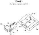
FIGURE 1 is a schematic representation of the cartridge and receptacle having a pair of opposed magnetic poles made in accordance with the present invention.FIGURE 2 is a front view of a cartridge embodying the present invention and the associated improvements with its stopper in place to illustrate the engagement of the stopper with the body of the cartridge.FIGURE 3 is a view similar toFigure 2 showing the stopper removed from the body of the cartridge.FIGURE 4 is a cross-sectional (A), magnified cross-sectional (B), and longitudinal-sectional (C) view.Figure 4A and 4B are cross-sectional views taken on theline 4A-4A ofFigure 3 .Figure 4B is an enlarged cross-sectional view of the adhesive trough on the edge of the shelf portion of the body juxtaposed to the optically clear edge of the land surface.Figure 4C is a longitudinal-section taken on the line of 4B-4B ofFigure 3 .FIGURE 5A, 5B , AND 5C are sectional views of the cartridge in loading position illustrating the cooperation between the cartridge body and the stopper to entrap the specimen in the cartridge in the absence of air.Figure 5A shows the stopper removed with the specimen in place within the chamber and the vestibule.Figure 5B is a view similar toFigure 5A showing the penetration of the probe of the stopper into the buffer within the vestibule.Figure 5C shows the stopper in place closing both the port between the chamber and the vestibule and the upper end of the vestibule.FIGURE 6 is a perspective view of the stopper shown inFigures 2-5 .FIGURE 7 is an enlarged fragmentary sectional view of the cartridge with the stopper operatively engaged with the body of the cartridge.- The device of the present invention has been improved to limit significant settling of target components prior to loading, thus enabling a uniform distribution of the array of magnetically responsive particles and magnetically labeled target components along the viewing surface. Because the biological sample is loaded into the cartridge in the presence of a magnetic field, an unequal distribution of magnetically labeled target components is ensured. Loading is accomplished by placing the cartridge vertically within a magnetic field prior to sample loading. The sample is then introduced into the cartridge chamber, closed with a stopper, and maintained until analyzed. Optical analysis is completed without settling and with a uniform distribution of target components that remains consistent from sample to sample.
- As with the cartridge from the parental application, the specimen sample can be introduced into the test chamber of the cartridge along with a buffer solution in which the respective properties of the specimen and the buffer solution are such as to provide an interface separating the buffer solution from the sample. The sample chamber is elongated with a port at one end. Preferably, the buffer solution is of a density less than or equal to the density of the sample so that when the chamber is disposed with the ported end upright, the buffer solution is positioned above the interface and the sample is positioned below the interface. During the filling of the chamber, any air or other contaminants, which are less dense than the buffer solution, are allowed to gravitate upwardly through the buffer solution towards the port in the upper end of the chamber. The chamber is designed with a vestibule containing an overflow reservoir capable of being sealed both from the test chamber and the exterior environment. A stopper is provided for sealing both ends of the vestibule through its attached probe, which extends into the buffer solution above the interface. As the stopper, through the probe, is engaged with the port of the test chamber, the probe displaces the buffer into the vestibule. The stopper now forms a primary seal, which closes the test sample chamber from the vestibule. Subsequently, the stopper forms a second seal to close the outside entrance of the vestibule to prevent escape of the buffer from the vestibule. The vestibule thus serves as an overflow receptacle. The first seal closes the test chamber after any deleterious air bubbles in the chamber have migrated into the vestibule. Thereafter, the second seal closes the overflow chamber to retain the buffer solution against loss with the simultaneous engagement of the stopper through an improved clip mechanism.
- Improvements on the stopper results in reduced expense and increased ease of cartridge handling. The improved stopper is composed of a single elastomer with a preferred durometer value of about 60 to 90. The stopper is locked into position in the cartridge by flexible walls so that when the second seal closes the overflow chamber the walls are compressed until they snap outwardly to position against their respective keeper elements. This interaction allows the stopper to lock into place, making stopper alignment with the chamber easier and making the stopper much more difficult to remove after filling.
- When in place, the stopper and handle permit the cartridge to be griped and manipulated into position with the optical detecting device in an orientation which positions the test chamber so that the target cells are in a suitable position within the field of observation for the detection equipment.
- Grips on the cartridge used for manipulating the cartridge into position have been improved by flaring-out the inward taper to allow a more secure grasp and better control. Accordingly, the cartridge may be easily mounted in a microscope or other detection equipment to allow positioning of the target components in the biological sample within the equipment's sample observation field. Within the handle portion and between the grip areas, the cartridge has improved support to prevent unintentional flexing thereby affecting the established seals between the stopper and cartridge.
- Finally, a novel type of manufacture for the attachment of the optical land surface to the plastic portion of the cartridge is described, said type of manufacture not being part of the invention. More specifically, a plastic edge is in contact with an optically clear land surface, which is usually glass. The edge is shaped as a small shelf to seat the land surface. The shelf spans the entire area to be in contact with the land surface. A small trough is positioned along the shelf, but within the area to be in contact. A binding adhesive is introduced into the trough and along the entire contact region. The binding adhesive is an optically clear adhesive that is non-fluorescent and unable to react with the sample. When the optically clear land surface is placed in contact with the shelf, the adhesive is channeled away from the optical path. This allows for a more reproducible and for a more consistent observation during optical analysis. While any adhesive with the characteristics described above will work, adhesives can be of a pressure-sensitive type, heat cured type, or activated by ultraviolet light.
- Optical analysis of biological samples, especially rare cells, requires a method and means to maintain the specimen in a condition that would allow inexpensive and reproducible. The improved sample cartridge and stopper, when used together, are designed to avoid contamination of the biological sample, but with an improved design and manufacture which allows for better control during any manipulation prior to optical analysis, uniform distribution of magnetically labeled target components for optical analysis, and at a lower cost to produce.
- One improvement in the preparation of the sample is to load and store the cartridge assembly, either the parental or improved version, within an applied magnetic field prior to sample filling and optical analysis. The cartridge is positioned vertically before loading within an applied magnetic field in preparation for sample loading. The sample is introduced into the cartridge chamber within the magnetic field, resulting in the prevention of any settling of magnetically responsive particles and any magnetically labeled target components. Accordingly, the magnetically labeled target components are arranged in an evenly distributed, which is consistently displayed from sample to sample. The magnetic field prevents these same magnetically labeled target components from clustering within one region of the cartridge prior to optical analysis. Thus after insertion of the stopper into the cartridge, the magnetically labeled target components of the biological sample will remain stably positioned along the flat land surface of the cartridge until removed from the magnetic field after analysis.
- The cartridge and stopper of the improved invention are particularly adapted for use in a detecting apparatus such as shown in
US Patent No. 6,013,532, which issued to Liberti et al. on January 11, 2000 , and described in a paper entitled "Optical Tracking and Detection of Immunomagnetically Selected and Aligned Cells" by Arjan G.J. Tibbe et al., Published in Nature Biotechnology, Vol. 17, December 1999, pp1210-121 3. The cartridge and receptacle, shown schematically inFigure 1 of the patent, is effective to immobilize magnetically labeled target entities, such as cells, within a fluid medium for observation, analysis or manipulation. The magnetically labeled target entities are deposited in a test chamber where they are manipulated by a magnetic field to dispose the magnetically labeled target entities in a monolayer along a wall of the test chamber. A discussion of automated magnetic separation techniques is included inU.S. Patent No. 5,985,153 which issued to Gerald J. Dolan et al. on November 16, 1999 , and in a paper entitled "Cell Analysis System Based on Immunomagnetic Cell Selection and Alignment Followed By Immunofluorescent Analysis Using Compact Disk Technologies" by Arjan G.J. Tibbe et al., published in Cytometry, 43:31-37 (2001). - Referring to
Figure 1 , an improved cartridge embodying the invention is shown at 21 mounted in areceptacle 20 having a pair of opposed magnetic poles, 22 and 23 which have a gap formed therebetween. In the illustrated detecting apparatus, thereceptacle 20 is positioned horizontally in the path of the optical system of the apparatus with the gap upwardly, but for other applications the receptacle may be positioned vertically. InFigure 1 , the lower surfaces of thepoles cartridge 21 to urge magnetically-responsive particles and magnetically labeled targets within the chamber towards the wall of the cartridge which is substantially co-planar with the gap. The magnetically labeled target entities are displayed as an orderly monolayer on the interior surface of the test chamber, and an automated observation system can be configured to provide relative motion between the cartridge and the light-gathering elements of the observation system in order to tract the collected magnetically labeled target entities for automated enumeration, which can include spectral analysis of light emitted, absorbed or scattered by the collected magnetically labeled targets. - The complete system comprises optical tracking beam analysis components similar to those employed for reading compact discs known in the audio and data storage arts (see
PCT/US02/04124 ). Briefly, a pair of laser diodes generates parallel beams of light. One beam is employed by the analysis system (not shown) for locating and tracking lines of the target entities. The other beam is used for detecting the presence of collected target entities adjacent to a located line. Relative motion between the cartridge and the optical elements of the analysis system is provided by a mechanical translation unit (not shown). Coordination of the functions of the analysis system is provided by a microprocessor (not shown). The tracking beam, which is reflected by dichroic mirror through the aperture is focused upon the upper surface of the cartridge by an objective lens. The dichroic mirror 7 through the dichroic lens and the objective lens reflects the detecting beam. - Light reflected by the tracking lines and the target entities will be transmitted through dichroic mirrors and toward a photo detector (not shown). The detector generates a data signal, which is fed to the microprocessor for the unit, as described more fully in the above-mentioned
US Patent No. 5,985,153 , to control the translation of the unit and process the data provided by the detector. - The
improved cartridge 21 may also be used in other detecting apparatus such as a microscope, as described in the above-mentionedU.S. Patent No. 6,013,532 , in which the stage is designed to receive thereceptacles 20 so as to position the surface of the cartridge in the light path of the microscope. As noted above, the orientation of the test chamber may be horizontal, vertical or at any angle determined by the instrumentation of the detecting apparatus. - As shown in the orientation of
Figure 1 , theimproved cartridge 21 has adomed body portion 51 having outwardly projectingglides grips 37 38, theglides guide ways poles guide ways slot 56 providing an optical path through the bottom of the receptacle. The optical path registers with the longitudinal centerline of the cartridge when the cartridge is inserted into position withinreceptacle 20. Figure 2 shows thecartridge 21 in front view embodying the present invention and the associated improvements with its stopper in place to illustrate the engagement of the stopper with the body of the cartridge. The stopper is shown withplug 74 sealingly engage. With the stopper fully inserted, theplug 74 closes the proximal end of the vestibule. The stopper has an improvedhandhold 75 and an improved locking mechanism composed of twoflexible walls flexible walls plug 74 and engage theirrespective keeper elements handle portion 61 of the cartridge. The improved keeper elements are supported at the top of the handle portion and laterally along the sides of the keeper elements. This provides extra rigid support when engaged as shown.Figure 3 shows thecartridge 21 in front view embodying the present invention and the associated improvements with its stopper removed to illustrate the difference when not engaged with the body of the cartridge- The improved cartridge is formed from a non-magnetic inert material, such as polycarbonate, polystyrene or acrylic with no fluorescent additives and is formed to provide a rigid chamber, which may be manipulated into and out of the optical path of the optical analysis system. A sectional view with the stopper removed shows the cartridge with flanking
grips flat land surface 62 formed from optically clear material such as glass and affixed at the top of the dome 51 (Figure 4A ). - A procedure for affixing the optically
clear land surface 62 to the cartridge is incorporated into the embodiment to provide better adhesion (seeFigure 4 ), a more consistent orientation of theland surface 62 with respect to the viewing aperture, but most importantly less interference with optical analysis due to excess adhesive in the chamber area. The procedure allows for a more even and controlled application of the adhesive along the interface between theland surface 62 and the top of the non-magneticallyinert dome 51. More specifically, the improved affixation prevents the adhesive from spreading in both lateral directions by forcing adhesive away from the chamber area. - Basically, the improvement is in the geometry of an
adhesive trough 12, which is designed to channel the adhesive away from the chamber area when the flat land surface is attached (Figure 4B ). The molded inert material of the cartridge dome is shaped as asmall shelf 15 at the edge to form the contact area with theflat land surface 62. A small trough, filled with adhesive, runs along the edge. The trough spans the entire contact area so that when the flat land surface is placed on the edge, contact is made with the adhesive. The adhesive is allowed to wick down the trough and across the contact area. This area is then exposed to UV light, heat cured, or treated by any means to securely bond the edge to the land surface. The preferred embodiment is to use a UV light adhesive to bond 0.5 mm thick glass cut to tight tolerances with molded plastic. The molded plastic must be non-fluorescent, rigid, optically clear, and non-reactive with the sample. Typical examples are polycarbonate or polystyrene. - The
land surface 62 is optically clear and permanently affixed to the cartridge. Thus when positioned in thereceptacle 20, thetest chamber 63 is aligned with theaperture 56 of the receptacle along the light path of the detecting apparatus in which receptacle 20 is mounted. This provides for an optimum analytical viewing surface. - The
test chamber 63 is closed at the distal end remote from thehandle portion 61 and has aninlet opening 65 at the proximal end adjacent thegrips 37, 38 (Figure 5A ). Theinlet 65 is positioned in the center of the end wall of thetest chamber 63 at the proximal end so that when the cartridge is disposed vertically for filling theinlet opening 65 is at the uppermost part of thechamber 63. The body of the cartridge provides avestibule chamber 66 having anenlarged mouth 67 at its entrance end. Thevestibule chamber 66 communicates with thetest chamber 63 through theinlet opening 65. Between themouth 67 and theinlet 65, the vestibule 66 provides an overflow reservoir, as described more fully hereinafter. - The
test chamber 63 is adapted to be closed by the plunger 71 of an improved stopper having aprobe 72 adapted for sealing through an engagement with theinlet 65 of thetest chamber 63. Rearwardly of theprobe 72, the stopper has a ribbedstem 73. The ribbed stem terminates into aplug 74, which is adapted to sealingly engage in themouth 67 as the stopper is fully inserted through thevestibule 66. When fully inserted, theplug 74 closes the proximal end of the vestibule 66. Beyond theplug 74, the stopper has an improvedhandhold 75 and an improved locking mechanism composed of twoflexible walls flexible walls plug 74 and engage theirrespective keeper elements handle portion 61 of the cartridge. The improved keeper elements are supported at the top of the handle portion and laterally along the sides of the keeper elements. This provides extra rigid support when engaged. When the flexible walls of thestopper improved keeper elements - The improved cartridge has a
handle portion 61 with associated grips enabling the insertion and removal of the cartridge into and out from the receptacle. Thehandle portion 61 has also been improved by flaring thegrips keeper elements enlarged mouth 67 of the vestibule. Changes to both faces provide a more secure lock for the stopper when engaged in position, and a much-improved rigid support for cartridge manipulation. - The projecting part of the stopper including the
probe 72 and theplug 74 comprise an elastomeric material such as a thermoplastic elastomer (DYNAFLEX®), or other elastomeric material capable of forming seals with theinlet 65 and themouth 67, respectively. The elastomeric material must also be non-fluorescent and non-reactive with the sample. The durometer of the elastomeric material is in the range of about 60 to 100 with a more preferred range of about 80 to 90 and the most preferred about 90. Thehandhold 75 of the stopper and theflexible walls stopper handhold 75 about its axis, especially after the flexible walls are securely locked into place. To release their engagement with thekeepers cartridge handhold 61 allows access for manual compression of the flexible walls and reversal of the engagement. Overall, this single elastomer design provides for a lower cost cartridge/stopper assembly. - As shown in
Figures 4C , the cartridge is disposed with its longitudinal axis horizontal so that theflat land area 62 of thetest chamber 63 is disposed within the field of observation of the detection equipment. When filling thetest chamber 63, the cartridge is disposed with its longitudinal axis upright with the vestibule 66 disposed above thetest chamber 63. - As shown in
Figures 5A to 5C , a test liquid is introduced into thetest chamber 63 along with any associated buffer solution. The buffer solution has a density which is less than or equal to the test liquid so that there is a liquid interface provided between the two solutions. The volume of the buffer solution is sufficient to completely fill thetest chamber 63. The filling operation excludes air from thetest chamber 63, and any air bubbles remaining in the buffer solution will gravitate upwardly through theinlet 65 into thevestibule 66. - The construction and arrangement of the chamber insures that air bubbles are excluded from the test chamber and pressure build-up in the unit is avoided. As shown in
Figures 5A to C , when thestopper 60 is inserted into the vestibule, a projecting portion containing theprobe 72 displaces the buffer solution as it enters the established fill line and causes the surface of the buffer solution to rise within the vestibule until theprobe 72 contacts theinlet 65. As shown, theinlet 65 has a flaredmouth 88 and acylindrical channel 89 below the flared mouth (Figure 5B ). At this point, the surface of the buffer solution is shifted upwardly to an elevated fill line. Further movement of the stopper downwardly causes the tip of theprobe 72 to enter thechannel 89 of theinlet 65. When theprobe 72 engages thecylindrical channel 89, the probe affects a first seal, closing communication between thetest chamber 89 and thevestibule 66. Further penetration of theprobe 72 into the cylindrical portion of thecylindrical channel 89 of theinlet 65 perfects the seal (Figure 5C ). Because the tip of theprobe 72 closes thecylindrical channel 89, and, in the present instance, the internal diameter of thechannel 89 of theinlet 65 is less than the internal dimensions of thechamber 63 so that the volume of buffer solution in the channel is minimal, and the engagement of theprobe 72 into thechannel 89 when effecting the first seal does not significantly increase the pressure within thetest chamber 63. The vestibule remains open at the top until theplug 74 enters themouth 67, allowing the vestibule to remain at ambient pressure. - The design of the present invention may be used for any analysis chamber, but it has been specifically created for analysis chambers for testing extremely small samples having a volume of less than 1 ml. In the illustrated embodiment, referring to
Figure 4B , the width of thechamber 63 below theland area 62 is approximately 3 mm and the depth is approximately 4 mm, providing a cross-sectional area in the range of 10 to 14 square millimeters. The length along the longitudinal axis is approximately 30 mm. The volume of thechamber 63 should be in the range between 22 ul and 675 ul, preferably at least 315 ul. The diameter of theinlet 65 is in the range between 0.0381 mm and 3.18 mm, and preferably is 2.35 mm, providing a flow area of approximately 10 square millimeters. Beyond theinlet 65, the vestibule flares out, in this case to a diameter of 4.23 mm, and extends approximately 14 mm to themouth 67, which, in this case, has a width of 6.3 mm. With the plug fully inserted, the volume of the vestibule 66 is preferably at least 95 ul. The width of the test chamber at the upper wall is slightly more than the diameter of thechannel 89 of the inlet 656. Although not shown in the figures, the corners around the perimeter of the upper wall are broken or beveled, so as to avoid entrapment of any air bubbles gravitating upwardly through thechamber 63. The bevel is preferably at an angle of between 2° and 30° relative to the longitudinal axis of thechamber 63 and theinlet 65. - Further displacement of the
stopper 60 allows theplug 74 at the proximal end of thestem 73 to engage in theenlarged mouth 67 of the vestibule and affect a second seal closing the upper end of the vestibule. As shown inFigures 6 and7 , theplug 74 is a rectangular block to mate with theenlarged mouth 67, which is in the form of a socket having a complementary rectangular form. Theblock 74 is of the same plastic material as theprobe 72 having sufficient resiliency to effect a good seal with theenlarged mouth 67 when engaged as shown inFigure 5C . The displacement of theplug 74 in theenlarged mouth 67 does not substantially increase the air pressure above the fill line 87. - The distance between the top of the
cylindrical channel 89 of theinlet 65 and the bottom of the socket forming theenlarged mouth 67 is less than the distance between the tip of theprobe 72 and the bottom of theplug 74 so that there is assurance that the probe enters into thechannel 89 before theplug 74 seats against the bottom of the socket. This arrangement insures avoidance of any substantial pressure build-up in thevestibule 66. It is noted that thestem 73 hasribs 91 spaced circumferentially there around so that the space between the ribs provides an adequate space to accommodate the buffer solution displaced during the penetration of the probe into thecylindrical portion 89 of the inlet. - With the flexible walls engaging the
keeper element 77 to keep the stopper in place, air is confined within the vestibule 66 between the first and second seals, and the cartridge may be manipulated without fear of air bubbles or the like interfering with the optical analysis of the liquid in thetest chamber 63. After being filled and capped, the cartridge may be reoriented so that its longitudinal axis is horizontal for analysis in the detecting apparatus, as described above and illustrated inFigures 1 to 4 , since thetest chamber 63 is completely filled with liquid, it may be manipulated into other orientations, as may be required by the detecting apparatus chosen by the analyst. Any buffer solution, which is in contact with the test liquid is retained within the cartridge, either in thetest chamber 63 or within the vestibule 66, and there is little danger of loss of any significant part of the test liquid. The buffer solution, which overlies the test liquid in the cartridge during the filling operation, assures minimal exposure of the test liquid to air and a diminished risk of deterioration or contamination of the test liquid. - While particular embodiments of the present invention have been herein illustrated and described, it is not intended to limit the invention to such disclosure, and many changes and modifications can be envisioned therein that may be made within the scope of the following claims.
Claims (5)
- A cartridge comprising:a body (51) of non-magnetic inert material adapted to be slidably engaged in a receptacle (20) of an apparatus for performing optical analysis of a fluid sample, said body (51) having a domed cross section transverse to a longitudinal axis with an optically clear flat land portion (62) adapted to be positioned in a field of observation for optical analysis;a test chamber (63) underlying said flat land portion (62) adapted to be filled vertically along the longitudinal axis with said fluid sample; anda vestibule (66) having an enlarged mouth (67) at an entrance end and communicating with the test chamber (63) through an inlet opening (65) opposite the entrance end, said vestibule (66) being disposed above said test chamber (63) when the cartridge is vertical and adapted to act as an overflow reservoir capable of being sealed both from said test chamber (63) and an exterior environment, when a stopper is provided for sealing the vestibule (66) at both the entrance end and the inlet opening (65),said body further comprising a handle portion (61) comprising two lateral sides with grips (37, 38) and an uppermost side with an opening for receiving the stopper, said handle portion (61) having an inner framed structure that is bounded laterally by two keeper elements (77, 77) for keeping the stopper in place and along the longitudinal axis by said uppermost portion and by the enlarged mouth (67) of said vestibule (66),said cartridge beingcharacterised in that:a. the lateral sides of the handle portion (61) flare outwardly towards the uppermost side of said handle portion (61); andb. the uppermost side of said handle portion (61) forms an arch-like extension facing away from the test chamber, and spanning between said lateral sides.
- A method for filling said test chamber (63) of said cartridge according to claim 1, with a test liquid containing magnetically responsive particles and magnetically labelled target components, the test chamber having a closed distal end and said inlet opening (65) at the proximal end, comprising:- positioning said cartridge (21) vertically with the inlet opening (65) at the uppermost part of the test chamber (63);- introducing said test liquid via the mouth (67) of the vestibule (66) into said test chamber (63) in a volume sufficient to fill said test chamber to a level either up to or below a fill line,- adding a buffer solution having a density different from the density of said test liquid when below said fill line with the combined volume of said liquid and said buffer being sufficient to bring the surface of said combined liquids to said fill line, said test liquid and buffer solution providing a liquid interface within the test chamber (63) with said buffer solution positioned above the interface and said test liquid positioned below the interface,- engaging the stopper with the inlet (65) of the test chamber thereby displacing said buffer solution into the vestibule (66) through a first seal interface, and excluding air from said test chamber (63) and precluding through a second seal voiding of said vestibule serving as overflow reservoir towards the exterior environment,the method beingcharacterised in that:the cartridge is positioned during the filling within a magnetic field which prevents magnetically responsive particles and magnetically labelled target components from settling towards the distal end of the test chamber (63); andsaid cartridge is stored within said magnetic field for use in an apparatus to perform optical analysis.
- The method of claim 2, wherein said filling in said magnetic field is performed within a receptacle (20) having a pair of magnetic poles (22, 23) to induce said magnetic field.
- The method of claim 3, wherein said filling in said magnetic field comprises:a. mounting said cartridge (21) onto said receptacle (20) having said pair of magnetic poles (22, 23) in opposing orientation and having a gap formed therebetween; andb. tapering lower surface of said poles (22, 23) toward said gap so that said magnetic field is applied to said test chamber (63) in such a way as to urge said magnetically responsive particles and said magnetically labeled target components within said test chamber towards a wall (62) of said cartridge (21).
- A cartridge according to claim 1, including a stopper having a probe (72) on a projecting stem of said stopper, said probe forming a first seal adapted to sealingly seat in said inlet opening (65) and close the same, said first seal precluding air entrapment within said test chamber (63) upon being seated in said inlet opening, said probe (72) having a distal end adapted to enter said inlet opening (65) of said test chamber (63) below an established fill level before said first seal closes said inlet opening, said distal end having a thickness sufficient to displace liquid upwardly through said inlet opening (65) and position the surface of said fluid sample in said vestibule (66) prior to said first seal closing said inlet opening and a plug (74) on said projecting stem of said stopper proximal to said probe (72), said plug (74) having a position along said projecting stem such that said vestibule (66) remains open to said environment until after closing of said inlet opening (65) by said probe (72) then said plug (74) engages with said enlarged mouth (67) on said vestibule (66) effecting a second seal to close upper end of vestibule, the stopper comprising:a. a single elastomer; andb. a locking mechanism to engage with said keeper elements (77, 77) on said cartridge, said mechanism having flexible walls (76, 76) on each side of a stopper handhold such that when said second seal closes the vestibule (66) said flexible walls are compressed until they snap outwardly and allow said stopper to lock into place.
Applications Claiming Priority (3)
| Application Number | Priority Date | Filing Date | Title |
|---|---|---|---|
| US303309 | 2002-11-25 | ||
| US10/303,309US7011794B2 (en) | 2002-11-25 | 2002-11-25 | Upon a cartridge for containing a specimen sample for optical analysis |
| PCT/US2003/037105WO2004048926A2 (en) | 2002-11-25 | 2003-11-20 | Improvement upon a cartridge for containing a specimen sample for optical analysis |
Publications (3)
| Publication Number | Publication Date |
|---|---|
| EP1581428A2 EP1581428A2 (en) | 2005-10-05 |
| EP1581428A4 EP1581428A4 (en) | 2006-06-14 |
| EP1581428B1true EP1581428B1 (en) | 2019-06-26 |
Family
ID=32324979
Family Applications (1)
| Application Number | Title | Priority Date | Filing Date |
|---|---|---|---|
| EP03786902.1AExpired - LifetimeEP1581428B1 (en) | 2002-11-25 | 2003-11-20 | Improvement upon a cartridge for containing a specimen sample for optical analysis |
Country Status (7)
| Country | Link |
|---|---|
| US (3) | US7011794B2 (en) |
| EP (1) | EP1581428B1 (en) |
| JP (1) | JP4494213B2 (en) |
| AU (1) | AU2003295701A1 (en) |
| CA (2) | CA2507549C (en) |
| ES (1) | ES2745433T3 (en) |
| WO (1) | WO2004048926A2 (en) |
Families Citing this family (63)
| Publication number | Priority date | Publication date | Assignee | Title |
|---|---|---|---|---|
| BR0207095A (en)* | 2001-02-12 | 2004-01-20 | Immunivest Corp | Method for sealing a chamber to prevent air entrapment in a test liquid, sealing system for sealing a test chamber to prevent entrapment of liquid inserted into the chamber, and cartridge containing a test chamber for use on apparatus for performing optical analysis of liquid specimens by optical observation |
| CA2474509C (en)* | 2002-02-14 | 2012-01-31 | Immunivest Corporation | Methods and algorithms for cell enumeration in a low-cost cytometer |
| US7764821B2 (en)* | 2002-02-14 | 2010-07-27 | Veridex, Llc | Methods and algorithms for cell enumeration in a low-cost cytometer |
| US8475495B2 (en) | 2004-04-08 | 2013-07-02 | Globus Medical | Polyaxial screw |
| US7503924B2 (en) | 2004-04-08 | 2009-03-17 | Globus Medical, Inc. | Polyaxial screw |
| US8189899B2 (en)* | 2004-07-30 | 2012-05-29 | Veridex, Llc | Methods and algorithms for cell enumeration in a low-cost cytometer |
| US7777885B2 (en)* | 2005-08-17 | 2010-08-17 | Veridex, Llc | Diagnostic imaging device for the analysis of circulating rare cells |
| US8337755B2 (en)* | 2006-03-13 | 2012-12-25 | Veridex, Llc | Operator independent programmable sample preparation and analysis system |
| US7722822B2 (en)* | 2006-03-23 | 2010-05-25 | Agilent Technologies, Inc. | Sample tube and vial processing system, and method for processing the sample |
| US7731414B2 (en) | 2007-02-08 | 2010-06-08 | Instrumentation Laboratory Company | Reagent cartridge mixing tube |
| US8003314B2 (en) | 2007-04-16 | 2011-08-23 | Diagnostic Hybrids, Inc. | Methods for direct fluorescent antibody virus detection in liquids |
| US8110101B2 (en)* | 2007-08-30 | 2012-02-07 | Veridex, Llc | Method and apparatus for imaging target components in a biological sample using permanent magnets |
| US7828968B2 (en)* | 2007-08-30 | 2010-11-09 | Veridex, Llc | Method and apparatus for imaging target components in a biological sample using permanent magnets |
| DE102008054313B4 (en) | 2008-11-03 | 2012-12-13 | Zenteris Gmbh | Cartridge and apparatus for assaying biological samples with temperature-controlled biological responses |
| USD633209S1 (en)* | 2008-11-27 | 2011-02-22 | Clondiag Gmbh | Cartridge for counting particles in blood |
| US8710836B2 (en) | 2008-12-10 | 2014-04-29 | Nanomr, Inc. | NMR, instrumentation, and flow meter/controller continuously detecting MR signals, from continuously flowing sample material |
| US8790916B2 (en) | 2009-05-14 | 2014-07-29 | Genestream, Inc. | Microfluidic method and system for isolating particles from biological fluid |
| US9128101B2 (en) | 2010-03-01 | 2015-09-08 | Caris Life Sciences Switzerland Holdings Gmbh | Biomarkers for theranostics |
| US9469876B2 (en) | 2010-04-06 | 2016-10-18 | Caris Life Sciences Switzerland Holdings Gmbh | Circulating biomarkers for metastatic prostate cancer |
| US9428547B2 (en) | 2010-04-21 | 2016-08-30 | Dna Electronics, Inc. | Compositions for isolating a target analyte from a heterogeneous sample |
| US20110262989A1 (en) | 2010-04-21 | 2011-10-27 | Nanomr, Inc. | Isolating a target analyte from a body fluid |
| US8841104B2 (en) | 2010-04-21 | 2014-09-23 | Nanomr, Inc. | Methods for isolating a target analyte from a heterogeneous sample |
| US9476812B2 (en) | 2010-04-21 | 2016-10-25 | Dna Electronics, Inc. | Methods for isolating a target analyte from a heterogeneous sample |
| US20120252038A1 (en) | 2011-04-01 | 2012-10-04 | Chianese David A | Steroid receptor assays |
| US9993269B2 (en) | 2011-07-15 | 2018-06-12 | Globus Medical, Inc. | Orthopedic fixation devices and methods of installation thereof |
| US8888827B2 (en) | 2011-07-15 | 2014-11-18 | Globus Medical, Inc. | Orthopedic fixation devices and methods of installation thereof |
| US9186187B2 (en) | 2011-07-15 | 2015-11-17 | Globus Medical, Inc. | Orthopedic fixation devices and methods of installation thereof |
| US9198694B2 (en) | 2011-07-15 | 2015-12-01 | Globus Medical, Inc. | Orthopedic fixation devices and methods of installation thereof |
| US9358047B2 (en) | 2011-07-15 | 2016-06-07 | Globus Medical, Inc. | Orthopedic fixation devices and methods of installation thereof |
| SI2734307T1 (en) | 2011-07-21 | 2020-10-30 | Menarini Silicon Biosystems S.P.A. | Assay to capture and detect circulating multiple myeloma cells from blood |
| US10466160B2 (en) | 2011-08-01 | 2019-11-05 | Celsee Diagnostics, Inc. | System and method for retrieving and analyzing particles |
| US9404864B2 (en) | 2013-03-13 | 2016-08-02 | Denovo Sciences, Inc. | System for imaging captured cells |
| US9174216B2 (en) | 2013-03-13 | 2015-11-03 | DeNovo Science, Inc. | System for capturing and analyzing cells |
| EP2739587B1 (en) | 2011-08-01 | 2020-05-27 | Denovo Sciences | Cell capture system |
| US9213043B2 (en) | 2012-05-15 | 2015-12-15 | Wellstat Diagnostics, Llc | Clinical diagnostic system including instrument and cartridge |
| US9075042B2 (en) | 2012-05-15 | 2015-07-07 | Wellstat Diagnostics, Llc | Diagnostic systems and cartridges |
| USD697226S1 (en)* | 2012-05-15 | 2014-01-07 | Wellstat Diagnostics, Llc | Sample cassette for a diagnostic instrument |
| US9625465B2 (en) | 2012-05-15 | 2017-04-18 | Defined Diagnostics, Llc | Clinical diagnostic systems |
| USD700355S1 (en)* | 2012-05-15 | 2014-02-25 | Wellstat Diagnostics, Llc | Sample cassette for a diagnostic instrument |
| US9995742B2 (en) | 2012-12-19 | 2018-06-12 | Dnae Group Holdings Limited | Sample entry |
| US10000557B2 (en) | 2012-12-19 | 2018-06-19 | Dnae Group Holdings Limited | Methods for raising antibodies |
| US9599610B2 (en) | 2012-12-19 | 2017-03-21 | Dnae Group Holdings Limited | Target capture system |
| US9434940B2 (en) | 2012-12-19 | 2016-09-06 | Dna Electronics, Inc. | Methods for universal target capture |
| US9551704B2 (en) | 2012-12-19 | 2017-01-24 | Dna Electronics, Inc. | Target detection |
| US9804069B2 (en) | 2012-12-19 | 2017-10-31 | Dnae Group Holdings Limited | Methods for degrading nucleic acid |
| US9752181B2 (en) | 2013-01-26 | 2017-09-05 | Denovo Sciences, Inc. | System and method for capturing and analyzing cells |
| US9707562B2 (en) | 2013-03-13 | 2017-07-18 | Denovo Sciences, Inc. | System for capturing and analyzing cells |
| US10391490B2 (en) | 2013-05-31 | 2019-08-27 | Celsee Diagnostics, Inc. | System and method for isolating and analyzing cells |
| US9856535B2 (en) | 2013-05-31 | 2018-01-02 | Denovo Sciences, Inc. | System for isolating cells |
| EP3158317B8 (en) | 2014-06-18 | 2020-01-01 | Zoetis Denmark ApS | A microfluidic detection system |
| DE102016104808A1 (en)* | 2016-03-15 | 2017-09-21 | Als Automated Lab Solutions Gmbh | Device for insertion into an imaging system |
| TWI689720B (en) | 2017-01-07 | 2020-04-01 | 美商伊路米納有限公司 | Solid inspection apparatus and method of use |
| US10391492B2 (en) | 2017-08-29 | 2019-08-27 | Celsee Diagnostics, Inc. | System and method for isolating and analyzing cells |
| CN108303380A (en)* | 2018-01-26 | 2018-07-20 | 信阳农林学院 | A kind of optical spectrum analyser for analyzing different types of sample |
| US11375986B1 (en)* | 2018-07-27 | 2022-07-05 | The University Of Chicago | Device and method for stool sample collection |
| US10633693B1 (en) | 2019-04-16 | 2020-04-28 | Celsee Diagnostics, Inc. | System and method for leakage control in a particle capture system |
| US11273439B2 (en) | 2019-05-07 | 2022-03-15 | Bio-Rad Laboratories, Inc. | System and method for target material retrieval from microwells |
| EP3966307B1 (en) | 2019-05-07 | 2024-11-20 | Bio-Rad Laboratories, Inc. | System and method for automated single cell processing |
| JP7356519B2 (en) | 2019-06-14 | 2023-10-04 | バイオ-ラッド ラボラトリーズ インコーポレイテッド | Systems and methods for automated single cell processing and analysis |
| US11504719B2 (en) | 2020-03-12 | 2022-11-22 | Bio-Rad Laboratories, Inc. | System and method for receiving and delivering a fluid for sample processing |
| PT4208719T (en)* | 2020-09-02 | 2025-01-10 | Menarini Silicon Biosystems Spa | System, kit, method and process for handling a sample |
| CA3198157A1 (en)* | 2020-12-21 | 2022-06-30 | Conservation X Labs, Inc. | Systems and methods using hand-held devices for detecting a target analyte loaded on a cartridge |
| CN112730193A (en)* | 2020-12-23 | 2021-04-30 | 宁波大禾仪器有限公司 | Blood penetrability test equipment for protective clothing cloth |
Citations (1)
| Publication number | Priority date | Publication date | Assignee | Title |
|---|---|---|---|---|
| US5504011A (en)* | 1994-10-21 | 1996-04-02 | International Technidyne Corporation | Portable test apparatus and associated method of performing a blood coagulation test |
Family Cites Families (44)
| Publication number | Priority date | Publication date | Assignee | Title |
|---|---|---|---|---|
| US3124281A (en)* | 1964-03-10 | stull | ||
| US2170173A (en)* | 1936-07-30 | 1939-08-22 | John E Wheatley | Nonpouring self-measuring dispensing container |
| US2849739A (en)* | 1952-11-04 | 1958-09-02 | A H Wirz Inc | Sealing nitrocellulose cement |
| US3276640A (en)* | 1965-03-08 | 1966-10-04 | Kessler Milton | Closable pouring spout and an axially slidable cap moving a plug thereon for liquid containers |
| DE3036139A1 (en)* | 1980-09-25 | 1982-05-06 | Hans 8801 Schillingsfürst Heinlein | SPOUT FOR BOTTLE-LIKE CONTAINERS |
| US4543093A (en)* | 1982-12-20 | 1985-09-24 | Becton, Dickinson And Company | Variable sealing pressure plunger rod assembly |
| IT8322185V0 (en)* | 1983-06-22 | 1983-06-22 | Victor Wassilieff | CLOSING DEVICE FOR FLUID CONTAINERS. |
| US4559464A (en)* | 1983-06-27 | 1985-12-17 | General Electric Company | Molded commutator and method of manufacture |
| DE3524196C3 (en)* | 1984-07-06 | 1994-08-04 | Canon Kk | Lithography mask |
| US4859610A (en)* | 1985-06-05 | 1989-08-22 | Synbiotics Corporation | Immunoassay incubation device |
| US4933291A (en)* | 1986-12-22 | 1990-06-12 | Eastman Kodak Company | Centrifugable pipette tip and pipette therefor |
| US5089417A (en)* | 1987-07-01 | 1992-02-18 | Miles Inc. | Fluid separation and processing device |
| US4849173A (en)* | 1987-07-24 | 1989-07-18 | Chang Mao Kuei | Excrement examination unit |
| US4879173A (en)* | 1988-01-06 | 1989-11-07 | Georgia-Pacific Corporation | Glass mat with reinforcing binder |
| US5597733A (en)* | 1988-07-25 | 1997-01-28 | Precision Systems, Inc. | Automatic multiple-sample multiple-reagent dispensing method in chemical analyzer |
| US5026526A (en)* | 1990-02-09 | 1991-06-25 | Eastman Kodak Company | Automated capping means for analyzer pipette |
| GB9013728D0 (en)* | 1990-06-20 | 1990-08-08 | Waddington & Duval Ltd | Improvements in and relating to dispensing taps |
| US5179862A (en)* | 1990-06-29 | 1993-01-19 | Panametrics, Inc. | Snap-on flow measurement system |
| US6013532A (en)* | 1990-09-26 | 2000-01-11 | Immunivest Corporation | Methods for magnetic immobilization and manipulation of cells |
| EP0479448A3 (en)* | 1990-10-02 | 1992-12-23 | Beckman Instruments, Inc. | Magnetic separation device |
| JPH0726701Y2 (en)* | 1991-03-08 | 1995-06-14 | 東洋製罐株式会社 | Sample collection container |
| US5149506A (en)* | 1991-08-09 | 1992-09-22 | Sage Products, Inc. | Stool collection and transport device |
| US5242660A (en)* | 1992-02-28 | 1993-09-07 | Paul Hsei | Sample preparation device |
| US5302348A (en)* | 1992-12-10 | 1994-04-12 | Itc Corporation | Blood coagulation time test apparatus and method |
| US5578269A (en)* | 1993-06-11 | 1996-11-26 | Ortho Diagnostic Systems Inc. | Automated blood analysis system with an integral centrifuge |
| AU1911795A (en)* | 1994-02-09 | 1995-08-29 | Abbott Laboratories | Diagnostic flow cell device |
| US5658801A (en)* | 1994-05-03 | 1997-08-19 | Spectral Diagnostics Inc. | Medical test kit |
| DE4420719C2 (en)* | 1994-06-15 | 1997-11-20 | Henkel Kgaa | Membrane-sealed tube with needle lock |
| MX9701792A (en)* | 1994-09-08 | 1997-06-28 | Johnson & Johnson | Optically readable strip for analyte detection having on-strip standard. |
| US5728352A (en)* | 1994-11-14 | 1998-03-17 | Advanced Care Products | Disposable electronic diagnostic instrument |
| US5882942A (en)* | 1995-02-15 | 1999-03-16 | Wako Pure Chemical Industries, Ltd. | Method for sampling feces |
| US5814275A (en)* | 1995-02-15 | 1998-09-29 | Akzo Nobel N.V. | Obstruction detector for a fluid flow line of a medical laboratory instrument |
| DE69729101T2 (en)* | 1996-06-07 | 2005-05-12 | Immunivest Corp., Wilmington | MAGNETIC SEPARATION WITH THE HELP OF EXTERNAL AND INTERNAL GRADIENTS |
| US5714123A (en)* | 1996-09-30 | 1998-02-03 | Lifescan, Inc. | Protective shield for a blood glucose strip |
| US5772966A (en)* | 1997-01-24 | 1998-06-30 | Maracas; George N. | Assay dispensing apparatus |
| US6342183B1 (en)* | 1997-02-14 | 2002-01-29 | Escreen | System for collecting and locally analyzing a fluid specimen |
| US6009339A (en)* | 1997-02-27 | 1999-12-28 | Terumo Cardiovascular Systems Corporation | Blood parameter measurement device |
| US5958349A (en)* | 1997-02-28 | 1999-09-28 | Cepheid | Reaction vessel for heat-exchanging chemical processes |
| US5910287A (en)* | 1997-06-03 | 1999-06-08 | Aurora Biosciences Corporation | Low background multi-well plates with greater than 864 wells for fluorescence measurements of biological and biochemical samples |
| US6271046B1 (en)* | 1997-10-06 | 2001-08-07 | Enterix, Inc. | Apparatus and method for analyte detection |
| US6184040B1 (en)* | 1998-02-12 | 2001-02-06 | Polaroid Corporation | Diagnostic assay system and method |
| US6239445B1 (en)* | 1999-03-01 | 2001-05-29 | Bayer Corporation | Optical inspection apparatus with removable inserts |
| BR0207095A (en)* | 2001-02-12 | 2004-01-20 | Immunivest Corp | Method for sealing a chamber to prevent air entrapment in a test liquid, sealing system for sealing a test chamber to prevent entrapment of liquid inserted into the chamber, and cartridge containing a test chamber for use on apparatus for performing optical analysis of liquid specimens by optical observation |
| ATE524236T1 (en)* | 2002-01-28 | 2011-09-15 | Nanosphere Inc | HYBRIDIZATION DEVICE |
- 2002
- 2002-11-25USUS10/303,309patent/US7011794B2/ennot_activeExpired - Lifetime
- 2003
- 2003-11-20WOPCT/US2003/037105patent/WO2004048926A2/enactiveSearch and Examination
- 2003-11-20JPJP2004555506Apatent/JP4494213B2/ennot_activeExpired - Lifetime
- 2003-11-20CACA2507549Apatent/CA2507549C/ennot_activeExpired - Fee Related
- 2003-11-20AUAU2003295701Apatent/AU2003295701A1/ennot_activeAbandoned
- 2003-11-20EPEP03786902.1Apatent/EP1581428B1/ennot_activeExpired - Lifetime
- 2003-11-20CACA2738577Apatent/CA2738577C/ennot_activeExpired - Fee Related
- 2003-11-20ESES03786902Tpatent/ES2745433T3/ennot_activeExpired - Lifetime
- 2005
- 2005-12-05USUS11/294,012patent/US7815863B2/enactiveActive
- 2010
- 2010-09-06USUS12/876,189patent/US20100326587A1/ennot_activeAbandoned
Patent Citations (1)
| Publication number | Priority date | Publication date | Assignee | Title |
|---|---|---|---|---|
| US5504011A (en)* | 1994-10-21 | 1996-04-02 | International Technidyne Corporation | Portable test apparatus and associated method of performing a blood coagulation test |
Also Published As
| Publication number | Publication date |
|---|---|
| EP1581428A2 (en) | 2005-10-05 |
| ES2745433T3 (en) | 2020-03-02 |
| EP1581428A4 (en) | 2006-06-14 |
| CA2738577A1 (en) | 2004-06-10 |
| JP2006510007A (en) | 2006-03-23 |
| JP4494213B2 (en) | 2010-06-30 |
| AU2003295701A1 (en) | 2004-06-18 |
| US7815863B2 (en) | 2010-10-19 |
| WO2004048926A3 (en) | 2005-04-28 |
| CA2507549C (en) | 2011-07-12 |
| US20060115380A1 (en) | 2006-06-01 |
| AU2003295701A8 (en) | 2004-06-18 |
| US20100326587A1 (en) | 2010-12-30 |
| US20040101443A1 (en) | 2004-05-27 |
| US7011794B2 (en) | 2006-03-14 |
| WO2004048926A2 (en) | 2004-06-10 |
| CA2738577C (en) | 2016-05-03 |
| CA2507549A1 (en) | 2004-06-10 |
Similar Documents
| Publication | Publication Date | Title |
|---|---|---|
| EP1581428B1 (en) | Improvement upon a cartridge for containing a specimen sample for optical analysis | |
| CA2708573C (en) | Cartridge for containing a specimen sample for optical analysis | |
| AU2002243968A1 (en) | Cartridge for containing a specimen sample for optical analysis | |
| CZ20033357A3 (en) | Testing system | |
| US20060235335A1 (en) | Device having a self sealing fluid port | |
| EP0901821B1 (en) | Collection container assembly | |
| EP2344393B1 (en) | Devices for containing materials and methods of using and making same | |
| US5316731A (en) | Device for collection and processing of biological samples | |
| US20210252508A1 (en) | Sample cartridges |
Legal Events
| Date | Code | Title | Description |
|---|---|---|---|
| PUAI | Public reference made under article 153(3) epc to a published international application that has entered the european phase | Free format text:ORIGINAL CODE: 0009012 | |
| 17P | Request for examination filed | Effective date:20050613 | |
| AK | Designated contracting states | Kind code of ref document:A2 Designated state(s):AT BE BG CH CY CZ DE DK EE ES FI FR GB GR HU IE IT LI LU MC NL PT RO SE SI SK TR | |
| AX | Request for extension of the european patent | Extension state:AL LT LV MK | |
| DAX | Request for extension of the european patent (deleted) | ||
| RIC1 | Information provided on ipc code assigned before grant | Ipc:G01N 33/543 20060101ALI20060307BHEP Ipc:B01L 3/00 20060101ALI20060307BHEP Ipc:B65B 3/24 20060101AFI20050509BHEP Ipc:G01N 21/11 20060101ALI20060307BHEP Ipc:G01N 21/03 20060101ALI20060307BHEP Ipc:G01N 35/10 20060101ALI20060307BHEP | |
| A4 | Supplementary search report drawn up and despatched | Effective date:20060517 | |
| 17Q | First examination report despatched | Effective date:20100624 | |
| STAA | Information on the status of an ep patent application or granted ep patent | Free format text:STATUS: EXAMINATION IS IN PROGRESS | |
| GRAP | Despatch of communication of intention to grant a patent | Free format text:ORIGINAL CODE: EPIDOSNIGR1 | |
| STAA | Information on the status of an ep patent application or granted ep patent | Free format text:STATUS: GRANT OF PATENT IS INTENDED | |
| INTG | Intention to grant announced | Effective date:20181005 | |
| RIC1 | Information provided on ipc code assigned before grant | Ipc:G01N 33/543 20060101ALI20060307BHEP Ipc:G01N 21/11 20060101ALI20060307BHEP Ipc:B65B 3/24 20060101AFI20050509BHEP Ipc:G01N 21/03 20060101ALI20060307BHEP Ipc:G01N 35/10 20060101ALI20060307BHEP Ipc:B01L 3/00 20060101ALI20060307BHEP | |
| GRAS | Grant fee paid | Free format text:ORIGINAL CODE: EPIDOSNIGR3 | |
| RAP1 | Party data changed (applicant data changed or rights of an application transferred) | Owner name:MENARINI SILICON BIOSYSTEMS S.P.A. | |
| GRAA | (expected) grant | Free format text:ORIGINAL CODE: 0009210 | |
| STAA | Information on the status of an ep patent application or granted ep patent | Free format text:STATUS: THE PATENT HAS BEEN GRANTED | |
| REG | Reference to a national code | Ref country code:DE Ref legal event code:R081 Ref document number:60352117 Country of ref document:DE Owner name:MENARINI SILICON BIOSYSTEMS S.P.A., IT Free format text:FORMER OWNER: IMMUNIVEST CORP., WILMINGTON, DEL., US | |
| AK | Designated contracting states | Kind code of ref document:B1 Designated state(s):AT BE BG CH CY CZ DE DK EE ES FI FR GB GR HU IE IT LI LU MC NL PT RO SE SI SK TR | |
| REG | Reference to a national code | Ref country code:GB Ref legal event code:FG4D | |
| REG | Reference to a national code | Ref country code:CH Ref legal event code:EP | |
| REG | Reference to a national code | Ref country code:DE Ref legal event code:R096 Ref document number:60352117 Country of ref document:DE | |
| REG | Reference to a national code | Ref country code:AT Ref legal event code:REF Ref document number:1148015 Country of ref document:AT Kind code of ref document:T Effective date:20190715 | |
| REG | Reference to a national code | Ref country code:IE Ref legal event code:FG4D | |
| REG | Reference to a national code | Ref country code:NL Ref legal event code:MP Effective date:20190626 | |
| PG25 | Lapsed in a contracting state [announced via postgrant information from national office to epo] | Ref country code:SE Free format text:LAPSE BECAUSE OF FAILURE TO SUBMIT A TRANSLATION OF THE DESCRIPTION OR TO PAY THE FEE WITHIN THE PRESCRIBED TIME-LIMIT Effective date:20190626 Ref country code:FI Free format text:LAPSE BECAUSE OF FAILURE TO SUBMIT A TRANSLATION OF THE DESCRIPTION OR TO PAY THE FEE WITHIN THE PRESCRIBED TIME-LIMIT Effective date:20190626 | |
| PG25 | Lapsed in a contracting state [announced via postgrant information from national office to epo] | Ref country code:BG Free format text:LAPSE BECAUSE OF FAILURE TO SUBMIT A TRANSLATION OF THE DESCRIPTION OR TO PAY THE FEE WITHIN THE PRESCRIBED TIME-LIMIT Effective date:20190926 | |
| REG | Reference to a national code | Ref country code:AT Ref legal event code:MK05 Ref document number:1148015 Country of ref document:AT Kind code of ref document:T Effective date:20190626 | |
| PG25 | Lapsed in a contracting state [announced via postgrant information from national office to epo] | Ref country code:SK Free format text:LAPSE BECAUSE OF FAILURE TO SUBMIT A TRANSLATION OF THE DESCRIPTION OR TO PAY THE FEE WITHIN THE PRESCRIBED TIME-LIMIT Effective date:20190626 Ref country code:PT Free format text:LAPSE BECAUSE OF FAILURE TO SUBMIT A TRANSLATION OF THE DESCRIPTION OR TO PAY THE FEE WITHIN THE PRESCRIBED TIME-LIMIT Effective date:20191028 Ref country code:CZ Free format text:LAPSE BECAUSE OF FAILURE TO SUBMIT A TRANSLATION OF THE DESCRIPTION OR TO PAY THE FEE WITHIN THE PRESCRIBED TIME-LIMIT Effective date:20190626 Ref country code:NL Free format text:LAPSE BECAUSE OF FAILURE TO SUBMIT A TRANSLATION OF THE DESCRIPTION OR TO PAY THE FEE WITHIN THE PRESCRIBED TIME-LIMIT Effective date:20190626 Ref country code:RO Free format text:LAPSE BECAUSE OF FAILURE TO SUBMIT A TRANSLATION OF THE DESCRIPTION OR TO PAY THE FEE WITHIN THE PRESCRIBED TIME-LIMIT Effective date:20190626 Ref country code:AT Free format text:LAPSE BECAUSE OF FAILURE TO SUBMIT A TRANSLATION OF THE DESCRIPTION OR TO PAY THE FEE WITHIN THE PRESCRIBED TIME-LIMIT Effective date:20190626 Ref country code:EE Free format text:LAPSE BECAUSE OF FAILURE TO SUBMIT A TRANSLATION OF THE DESCRIPTION OR TO PAY THE FEE WITHIN THE PRESCRIBED TIME-LIMIT Effective date:20190626 | |
| REG | Reference to a national code | Ref country code:ES Ref legal event code:FG2A Ref document number:2745433 Country of ref document:ES Kind code of ref document:T3 Effective date:20200302 | |
| PG25 | Lapsed in a contracting state [announced via postgrant information from national office to epo] | Ref country code:TR Free format text:LAPSE BECAUSE OF FAILURE TO SUBMIT A TRANSLATION OF THE DESCRIPTION OR TO PAY THE FEE WITHIN THE PRESCRIBED TIME-LIMIT Effective date:20190626 | |
| PG25 | Lapsed in a contracting state [announced via postgrant information from national office to epo] | Ref country code:DK Free format text:LAPSE BECAUSE OF FAILURE TO SUBMIT A TRANSLATION OF THE DESCRIPTION OR TO PAY THE FEE WITHIN THE PRESCRIBED TIME-LIMIT Effective date:20190626 | |
| REG | Reference to a national code | Ref country code:DE Ref legal event code:R097 Ref document number:60352117 Country of ref document:DE | |
| REG | Reference to a national code | Ref country code:CH Ref legal event code:PL | |
| PLBE | No opposition filed within time limit | Free format text:ORIGINAL CODE: 0009261 | |
| STAA | Information on the status of an ep patent application or granted ep patent | Free format text:STATUS: NO OPPOSITION FILED WITHIN TIME LIMIT | |
| PG25 | Lapsed in a contracting state [announced via postgrant information from national office to epo] | Ref country code:MC Free format text:LAPSE BECAUSE OF FAILURE TO SUBMIT A TRANSLATION OF THE DESCRIPTION OR TO PAY THE FEE WITHIN THE PRESCRIBED TIME-LIMIT Effective date:20190626 Ref country code:LI Free format text:LAPSE BECAUSE OF NON-PAYMENT OF DUE FEES Effective date:20191130 Ref country code:CH Free format text:LAPSE BECAUSE OF NON-PAYMENT OF DUE FEES Effective date:20191130 Ref country code:LU Free format text:LAPSE BECAUSE OF NON-PAYMENT OF DUE FEES Effective date:20191120 | |
| 26N | No opposition filed | Effective date:20200603 | |
| REG | Reference to a national code | Ref country code:BE Ref legal event code:MM Effective date:20191130 | |
| PG25 | Lapsed in a contracting state [announced via postgrant information from national office to epo] | Ref country code:SI Free format text:LAPSE BECAUSE OF FAILURE TO SUBMIT A TRANSLATION OF THE DESCRIPTION OR TO PAY THE FEE WITHIN THE PRESCRIBED TIME-LIMIT Effective date:20190626 | |
| PG25 | Lapsed in a contracting state [announced via postgrant information from national office to epo] | Ref country code:IE Free format text:LAPSE BECAUSE OF NON-PAYMENT OF DUE FEES Effective date:20191120 | |
| PG25 | Lapsed in a contracting state [announced via postgrant information from national office to epo] | Ref country code:BE Free format text:LAPSE BECAUSE OF NON-PAYMENT OF DUE FEES Effective date:20191130 | |
| REG | Reference to a national code | Ref country code:DE Ref legal event code:R082 Ref document number:60352117 Country of ref document:DE Representative=s name:REBLE & KESSELHUT PARTNERSCHAFTSGESELLSCHAFT V, DE | |
| PG25 | Lapsed in a contracting state [announced via postgrant information from national office to epo] | Ref country code:CY Free format text:LAPSE BECAUSE OF FAILURE TO SUBMIT A TRANSLATION OF THE DESCRIPTION OR TO PAY THE FEE WITHIN THE PRESCRIBED TIME-LIMIT Effective date:20190626 | |
| PG25 | Lapsed in a contracting state [announced via postgrant information from national office to epo] | Ref country code:GR Free format text:LAPSE BECAUSE OF FAILURE TO SUBMIT A TRANSLATION OF THE DESCRIPTION OR TO PAY THE FEE WITHIN THE PRESCRIBED TIME-LIMIT Effective date:20190626 | |
| PG25 | Lapsed in a contracting state [announced via postgrant information from national office to epo] | Ref country code:HU Free format text:LAPSE BECAUSE OF FAILURE TO SUBMIT A TRANSLATION OF THE DESCRIPTION OR TO PAY THE FEE WITHIN THE PRESCRIBED TIME-LIMIT; INVALID AB INITIO Effective date:20031120 | |
| PGFP | Annual fee paid to national office [announced via postgrant information from national office to epo] | Ref country code:FR Payment date:20221010 Year of fee payment:20 | |
| PGFP | Annual fee paid to national office [announced via postgrant information from national office to epo] | Ref country code:IT Payment date:20221011 Year of fee payment:20 Ref country code:GB Payment date:20221006 Year of fee payment:20 Ref country code:ES Payment date:20221208 Year of fee payment:20 Ref country code:DE Payment date:20221011 Year of fee payment:20 | |
| P01 | Opt-out of the competence of the unified patent court (upc) registered | Effective date:20230530 | |
| REG | Reference to a national code | Ref country code:DE Ref legal event code:R071 Ref document number:60352117 Country of ref document:DE | |
| REG | Reference to a national code | Ref country code:ES Ref legal event code:FD2A Effective date:20231127 | |
| REG | Reference to a national code | Ref country code:GB Ref legal event code:PE20 Expiry date:20231119 | |
| PG25 | Lapsed in a contracting state [announced via postgrant information from national office to epo] | Ref country code:GB Free format text:LAPSE BECAUSE OF EXPIRATION OF PROTECTION Effective date:20231119 | |
| PG25 | Lapsed in a contracting state [announced via postgrant information from national office to epo] | Ref country code:ES Free format text:LAPSE BECAUSE OF EXPIRATION OF PROTECTION Effective date:20231121 | |
| PG25 | Lapsed in a contracting state [announced via postgrant information from national office to epo] | Ref country code:GB Free format text:LAPSE BECAUSE OF EXPIRATION OF PROTECTION Effective date:20231119 Ref country code:ES Free format text:LAPSE BECAUSE OF EXPIRATION OF PROTECTION Effective date:20231121 |