EP1581291B1 - Drug delivery apparatus - Google Patents
Drug delivery apparatusDownload PDFInfo
- Publication number
- EP1581291B1 EP1581291B1EP03777000AEP03777000AEP1581291B1EP 1581291 B1EP1581291 B1EP 1581291B1EP 03777000 AEP03777000 AEP 03777000AEP 03777000 AEP03777000 AEP 03777000AEP 1581291 B1EP1581291 B1EP 1581291B1
- Authority
- EP
- European Patent Office
- Prior art keywords
- time
- inhalation
- person
- seconds
- patient
- Prior art date
- Legal status (The legal status is an assumption and is not a legal conclusion. Google has not performed a legal analysis and makes no representation as to the accuracy of the status listed.)
- Expired - Lifetime
Links
- 238000012377drug deliveryMethods0.000titleclaimsdescription19
- 239000003814drugSubstances0.000claimsabstractdescription30
- 229940079593drugDrugs0.000claimsabstractdescription30
- 238000001514detection methodMethods0.000claimsabstractdescription5
- 239000000443aerosolSubstances0.000claimsdescription43
- 230000011664signalingEffects0.000claimsdescription17
- 230000000007visual effectEffects0.000claimsdescription6
- 230000003247decreasing effectEffects0.000claimsdescription5
- 230000029058respiratory gaseous exchangeEffects0.000abstractdescription16
- 238000011282treatmentMethods0.000description28
- 239000006199nebulizerSubstances0.000description23
- 210000004072lungAnatomy0.000description22
- 238000000034methodMethods0.000description17
- 238000002663nebulizationMethods0.000description14
- 239000000126substanceSubstances0.000description12
- 230000000241respiratory effectEffects0.000description9
- 230000008021depositionEffects0.000description7
- 238000002474experimental methodMethods0.000description7
- 238000000889atomisationMethods0.000description6
- 238000010586diagramMethods0.000description5
- 239000007788liquidSubstances0.000description5
- 125000006850spacer groupChemical group0.000description5
- 239000012530fluidSubstances0.000description4
- 206010049119Emotional distressDiseases0.000description3
- 230000008859changeEffects0.000description3
- 230000009429distressEffects0.000description3
- 230000000694effectsEffects0.000description3
- 230000008569processEffects0.000description3
- 230000009467reductionEffects0.000description3
- 230000002829reductive effectEffects0.000description3
- 238000012387aerosolizationMethods0.000description2
- 238000011156evaluationMethods0.000description2
- 208000024891symptomDiseases0.000description2
- 206010006322Breath holdingDiseases0.000description1
- 230000006978adaptationEffects0.000description1
- 230000003044adaptive effectEffects0.000description1
- 230000008901benefitEffects0.000description1
- 239000013078crystalSubstances0.000description1
- 230000005713exacerbationEffects0.000description1
- 230000002452interceptive effectEffects0.000description1
- 239000000463materialSubstances0.000description1
- 238000005259measurementMethods0.000description1
- 229940071648metered dose inhalerDrugs0.000description1
- 239000003595mistSubstances0.000description1
- 239000002245particleSubstances0.000description1
- 229920001296polysiloxanePolymers0.000description1
- 210000002345respiratory systemAnatomy0.000description1
- 208000023504respiratory system diseaseDiseases0.000description1
- 230000004044responseEffects0.000description1
- 230000000717retained effectEffects0.000description1
- 238000004062sedimentationMethods0.000description1
- 238000012360testing methodMethods0.000description1
- 230000036962time dependentEffects0.000description1
- 238000011144upstream manufacturingMethods0.000description1
Images


Classifications
- A—HUMAN NECESSITIES
- A61—MEDICAL OR VETERINARY SCIENCE; HYGIENE
- A61M—DEVICES FOR INTRODUCING MEDIA INTO, OR ONTO, THE BODY; DEVICES FOR TRANSDUCING BODY MEDIA OR FOR TAKING MEDIA FROM THE BODY; DEVICES FOR PRODUCING OR ENDING SLEEP OR STUPOR
- A61M15/00—Inhalators
- A61M15/0085—Inhalators using ultrasonics
- A—HUMAN NECESSITIES
- A61—MEDICAL OR VETERINARY SCIENCE; HYGIENE
- A61M—DEVICES FOR INTRODUCING MEDIA INTO, OR ONTO, THE BODY; DEVICES FOR TRANSDUCING BODY MEDIA OR FOR TAKING MEDIA FROM THE BODY; DEVICES FOR PRODUCING OR ENDING SLEEP OR STUPOR
- A61M15/00—Inhalators
- A61M15/0001—Details of inhalators; Constructional features thereof
- A61M15/002—Details of inhalators; Constructional features thereof with air flow regulating means
- A—HUMAN NECESSITIES
- A61—MEDICAL OR VETERINARY SCIENCE; HYGIENE
- A61M—DEVICES FOR INTRODUCING MEDIA INTO, OR ONTO, THE BODY; DEVICES FOR TRANSDUCING BODY MEDIA OR FOR TAKING MEDIA FROM THE BODY; DEVICES FOR PRODUCING OR ENDING SLEEP OR STUPOR
- A61M16/00—Devices for influencing the respiratory system of patients by gas treatment, e.g. ventilators; Tracheal tubes
- A61M16/0003—Accessories therefor, e.g. sensors, vibrators, negative pressure
- A61M2016/0015—Accessories therefor, e.g. sensors, vibrators, negative pressure inhalation detectors
- A61M2016/0018—Accessories therefor, e.g. sensors, vibrators, negative pressure inhalation detectors electrical
- A61M2016/0021—Accessories therefor, e.g. sensors, vibrators, negative pressure inhalation detectors electrical with a proportional output signal, e.g. from a thermistor
- A—HUMAN NECESSITIES
- A61—MEDICAL OR VETERINARY SCIENCE; HYGIENE
- A61M—DEVICES FOR INTRODUCING MEDIA INTO, OR ONTO, THE BODY; DEVICES FOR TRANSDUCING BODY MEDIA OR FOR TAKING MEDIA FROM THE BODY; DEVICES FOR PRODUCING OR ENDING SLEEP OR STUPOR
- A61M2205/00—General characteristics of the apparatus
- A61M2205/33—Controlling, regulating or measuring
- A61M2205/3375—Acoustical, e.g. ultrasonic, measuring means
- A—HUMAN NECESSITIES
- A61—MEDICAL OR VETERINARY SCIENCE; HYGIENE
- A61M—DEVICES FOR INTRODUCING MEDIA INTO, OR ONTO, THE BODY; DEVICES FOR TRANSDUCING BODY MEDIA OR FOR TAKING MEDIA FROM THE BODY; DEVICES FOR PRODUCING OR ENDING SLEEP OR STUPOR
- A61M2205/00—General characteristics of the apparatus
- A61M2205/33—Controlling, regulating or measuring
- A61M2205/3379—Masses, volumes, levels of fluids in reservoirs, flow rates
- A61M2205/3386—Low level detectors
- A—HUMAN NECESSITIES
- A61—MEDICAL OR VETERINARY SCIENCE; HYGIENE
- A61M—DEVICES FOR INTRODUCING MEDIA INTO, OR ONTO, THE BODY; DEVICES FOR TRANSDUCING BODY MEDIA OR FOR TAKING MEDIA FROM THE BODY; DEVICES FOR PRODUCING OR ENDING SLEEP OR STUPOR
- A61M2205/00—General characteristics of the apparatus
- A61M2205/58—Means for facilitating use, e.g. by people with impaired vision
- A61M2205/581—Means for facilitating use, e.g. by people with impaired vision by audible feedback
- A—HUMAN NECESSITIES
- A61—MEDICAL OR VETERINARY SCIENCE; HYGIENE
- A61M—DEVICES FOR INTRODUCING MEDIA INTO, OR ONTO, THE BODY; DEVICES FOR TRANSDUCING BODY MEDIA OR FOR TAKING MEDIA FROM THE BODY; DEVICES FOR PRODUCING OR ENDING SLEEP OR STUPOR
- A61M2205/00—General characteristics of the apparatus
- A61M2205/58—Means for facilitating use, e.g. by people with impaired vision
- A61M2205/582—Means for facilitating use, e.g. by people with impaired vision by tactile feedback
- A—HUMAN NECESSITIES
- A61—MEDICAL OR VETERINARY SCIENCE; HYGIENE
- A61M—DEVICES FOR INTRODUCING MEDIA INTO, OR ONTO, THE BODY; DEVICES FOR TRANSDUCING BODY MEDIA OR FOR TAKING MEDIA FROM THE BODY; DEVICES FOR PRODUCING OR ENDING SLEEP OR STUPOR
- A61M2205/00—General characteristics of the apparatus
- A61M2205/58—Means for facilitating use, e.g. by people with impaired vision
- A61M2205/583—Means for facilitating use, e.g. by people with impaired vision by visual feedback
- A—HUMAN NECESSITIES
- A61—MEDICAL OR VETERINARY SCIENCE; HYGIENE
- A61M—DEVICES FOR INTRODUCING MEDIA INTO, OR ONTO, THE BODY; DEVICES FOR TRANSDUCING BODY MEDIA OR FOR TAKING MEDIA FROM THE BODY; DEVICES FOR PRODUCING OR ENDING SLEEP OR STUPOR
- A61M2205/00—General characteristics of the apparatus
- A61M2205/58—Means for facilitating use, e.g. by people with impaired vision
- A61M2205/587—Lighting arrangements
Definitions
- the present inventionrelates to a drug delivery apparatus.
- a number of devicesare available for delivering a drug into the lungs of a patient.
- a pneumatic or jet type nebulizeris particularly effective in supplying an aerosolized drug for inhalation, but other types of nebulizer are also available, such as ultrasonic type nebulizers in which the drug to be atomized is forced through a mesh by vibration of a piezo-electric crystal, whereupon the droplets passing through the mesh are entrained in the air being inhaled by the patient.
- the gauge of the meshdetermines the size of the droplets which enter the airstream.
- Electrohydrodynamic (EHD) nebulizers and capillary micro jet nebulizersare also known. Alternatively, a dosimetric spacer can be used.
- the drugWhen using a spacer, the drug is introduced into a holding chamber of the spacer, either in areosolized form, or by loading the air within the holding chamber with the drug in powdered form. The patient breathes from the holding chamber thereby inhaling the drug laden air.
- spacersare particularly effective when treating children or elderly patients, and for use with certain drugs.
- the drugis normally delivered over a number of breaths.
- a pneumatic nebulizeris shown in EP 0627266 A2 in which air from a pressurized air source issues from an air outlet hole around which are disposed holes through which the liquid to be atomized is drawn out from a main reservoir. Each of these holes is within a groove forming a secondary reservoir around the air outlet hole.
- a deflector baris located across and in the path of the air issuing from the air outlet so that as it issues from the air outlet, it is immediately deflected across the top of the liquid outlet holes thereby creating low pressure regions drawing the liquid up from the main reservoir beneath, and atomizing that liquid as it is drawn from the holes.
- the droplets generated in this wayare carried to the patient for inhalation. Atomization can be switched on and off by switching on and off the pressurized air supply to the nebulizer.
- European patent publication number 0910421discloses a nebulizer, manufactured under the name Halolite, which delivers a drug during the first half of the patients inhalation in order to maximise lung deposition.
- the apparatusis interactive in that it measures the duration of a patient's inhalation and calculates a time period that is one half of an average of the patient's duration of inhalation. It is therefore able to match the delivery of the drug with the inhalation profile of the patient and takes account of changes in the patient's inhalation duration over time. It does not require the patient to perform a specific inhalation manoeuvre.
- a drug delivery system described in WO98/52633called the Akita system is known in which aerosolized drug is delivered to a patient in an airstream under a positive pressure delivered at 15 litres per minute up to a volume equivalent to 80% respiratory capacity.
- Respiratory capacityis defined as the inhalation volume measured from the end of a normal tidal exhalation to maximum lung capacity.
- the systemincludes controlled inhalation flow which prevents air from being delivered more quickly. This has the effect of lengthening the duration of inhalation.
- the systemdirects the patient when to breathe in, when to hold his breath, and when to exhale.
- the Akita systemmust first be set up with the patient in a clinic since the system must know the respiratory capacity of the patient in order to indicate the beginning of the breath hold step at the appropriate time. Different patients will have very different respiratory capacities depending on various factors including age, body size and the effect of any respiratory diseases. In addition, the duration of the breath hold must also be customised for particular patients to ensure that the patient will not suffer distress during the use of the system. If the breath hold is too long, then the patient will be unable to continue the treatment over a number breaths without suffering such distress. In addition, as the patient's symptoms change, then the system will need to be reconfigured to take account of this by another visit to a clinic.
- the document US 5,906,202discloses a device and method for directing an aerosol mist to a specific area of the respiration tract involving the use of a hand held metered dose inhaler which, when the patient begins to inhale, releases an aerosolized drug once a pre-set measured volume of air has been inhaled. Once a further pre-set volume of air has been inhaled, the device either prevents further inhalation or signals to the patient to stop inhalation whereupon the patient holds his breath for a given period of time after which the patient is indicated to continue with normal breathing.
- the document US 5,906,202discloses a drug delivery apparatus according to the preamble of claim 1.
- the drug delivery apparatuspreferably includes an airflow regulator for restricting the speed of the inhaled airstream through the device.
- the signalling devicemay be any one or more of an audio device, a visual device and a vibrator device.
- the audio devicemight emit a tone or a buzz.
- the visual devicemay include a screen, such as an LCD screen, or simple lights, possibly in the form of LED's.
- the vibrator devicecan signal to the person by causing the apparatus to vibrate thereby signalling to the person to stop inhaling.
- the controllerpreferably includes a calculator arranged to calculate the pre-set period of time.
- the controllermay be formed using a microprocessor.
- a method of generating signals in a drug delivery apparatus through which a person inhales to generate an inhaled airstreamcomprises the steps of detecting the commencement of inhalation, signalling to the person to cease inhalation after a pre-set period of time has elapsed from the detection of the commencement of breathing, and adjusting the pre-set period of time for subsequent inhalations depending on the time the person takes to stop inhaling after being signalled.
- the pre-set period of timemay be increased if the time taken to stop inhaling exceeds a first threshold time, and may be decreased if the time taken to stop inhaling is less than a second threshold time.
- the first threshold timeis normally greater than or equal to the second threshold time.
- the first threshold timeis preferably about 0.5 seconds.
- the first threshold timemay be in the range of 0.25 to 0.75 seconds, preferably in the range of 0.35 to 0.65 seconds, and most preferably in the range 0.45 to 0.55 seconds.
- the second threshold timeis preferably is about 0.3 seconds. It may be in the range of minus 0.2 to 0.5 seconds, preferably 0 to 0.4 seconds and most preferably 0.25 to 0.35 seconds.
- the methodpreferably further comprises the steps of detecting the end of inhalation and calculating the period of inhalation and the period of exhalation. This then allows all of the calculations necessary to be made.
- the methodmay include the step of calculating the inhalation to exhalation (I:E) ratio, and if it is greater than a third threshold, increasing the preset period of time. In this case, the third threshold of time is preferably about 1.
- the methodmay also include the step of calculating the I:E ratio, and if it is less than a fourth threshold, the preset period of time can be decreased. In this case, the fourth threshold of time is preferably about one third.
- the drug delivery apparatuscan be set up using the above mentioned method before it is used to deliver a drug. Alternatively, it can be done at the same time, whereby an aerosolized substance is delivered into at least a part of the inhaled air stream. Aerosol delivery is normally ceased before signalling to the person to cease inhalation. The aerosol delivery is ceased preferably at least one second before signalling to the person, and most preferably at least two seconds before signalling to the person.
- the time taken for the person to stop inhaling in response to the signalhas been found to be a good indication of whether or not the patient is experiencing distress, and so the pre-set period of time can be adjusted to accommodate the patient concerned and his particular requirements. This can be done without needing to visit a clinic. For example, if the person takes a relatively long time to stop inhaling, that is an indication that the pre-set period of time following the detection of the commencement or breathing can be lengthened. Conversely, if a person ceases to inhale very quickly after he is signalled to do so, or if he stops inhaling before signalled to stop, that will be an indication that the duration of the pre-set period of time is too long. The pre-set period can then be adjusted accordingly.
- the Akita and Halolite system described in the introductory part of this applicationwere used in an experiment in which a patient was supplied with a radio labelled aerosol.
- the aerosolwas radio labelled to allow scintigraphic evaluation of the experiment.
- the systemswere used in accordance with the manufacturers recommendations.
- a Sidestream nebulizer (Profile Respiratory Systems Ltd, Bognor Regis UK) and a nose clipwere used.
- the Akita systemprovided a positive pressure stream of air for inhalation at 15 litres per minute up to a volume equivalent to 80% of respiratory capacity with a breath hold of between 5 and 9 seconds.
- a computer screenprovided feedback to the patient as to the duration of inhalation and the breath holding pause required.
- the computer screendisplays a numerical countdown of the period over which the patient should inhale. At the end of that period of time, the person must hold his breath while the computer screen displays a further countdown of time until the patient is permitted to exhale.
- the patientbreathes in and out naturally without any feedback indicating to the person when to start inhaling, stop inhaling or carry out a breath hold. In fact, with the Halolite, since the person is intended to breathe in a slow relaxed manner, there will not be any breath hold period.
- the aerosol hold timeis referred to in this specification as the "aerosol hold time”. This contrasts with the Akita System in which atomisation occurs during the entire inhalation phase, and only stops once the patient begins his breath hold. Therefore, the aerosol hold time and the breath hold time are rather different, but have the same effect of defining a minimum period during which the aerosol is resident within the lung. After the breath hold the subject exhales through a filter in order to trap any of the aerosol.
- a treatment time of between 5 and 12 minuteswas needed to deliver a set dose of 0.4ml of Tc-DTPA from a 2.5ml nebulizer fill.
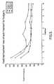
- FIG. 1the total residence time of the drug within the lungs is plotted against the total lung deposition as a percentage of the total aerosol delivered. It will be seen clearly that lung deposition increases with the total residence time. For example, a total residence time of 2 seconds is likely to result in less than 30% of the aerosol being deposited in the lungs, whereas doubling the residence time to 4 seconds will typically give a total lung deposition of more than 40%. By the time the total residence time reaches 12 seconds, the lung deposition reaches about two thirds of the aerosol delivered..
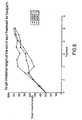
- Figure 2is a graph in which the aerosol hold time (Halolite System) and breath hold time (Akita System) is plotted against the exhaled filter fraction.
- the exhaled fractionis reduced with increasing aerosol hold time. It indicated that for a aerosol hold time in the order of 1 second exhaled losses are in the region of 15-20% but if the aerosol hold time is increased to 2 seconds the losses are reduced to 10%.
- Increasing the aerosol hold timeallows more time for the aerosol to deposit in the lung, as the principal method of deposition for particles of this size is sedimentation, which is time dependent.
- a drug delivery apparatuswhich is a mesh type nebulizer 1 for generating an aerosol indicated generally at 2 in a passageway 3.
- the passageway 3has an inlet 4 through which air enters it, and at its opposite end 5 the air passing through the passageway 3 is led to a mouthpiece or the like (not shown).
- the aerosol 2is entrained in the airflow leading to the mouthpiece.
- Nebulizationtakes place by a drug being forced through a mesh plate 6 by using an ultrasonic transducer 7 which drives a horn 8 to vibrate in the region of the mesh plate 6.
- the horn 8is located close to the rear face of the mesh plate 6 and is caused to vibrate by the ultrasonic transducer 7, whereby the aerosol 2 is generated from the front face of the mesh plate 6.
- the substance to be atomised into an aerosol 2is in fluid contact with the rear face of the mesh plate 6 and it is this that is driven through the holes of the mesh plate 6 by the vibrating horn 8.
- a certain volume of the substance to be atomisedis located in a reservoir 9 which is located above the mesh plate 6 in which to feed the substance to be atomised to its rear face.
- a fluid sensor 10is located between the reservoir 9 and the mesh plate 6 such that once the substance to be atomised has substantially all been aerosolized, this is detected so that the ultrasonic transducer 7 may be switched off at the end of treatment.
- a power supply 11is used to power the atomiser since power is required to drive aerosolization.
- An electronic controller 12controls the ultrasonic transducer 7 so that, for example, once the fluid sensor 10 senses that there is no liquid remaining to be atomised, the ultrasonic transducer 7 will be switched off.
- a more sophisticated control devicecan be used here such that the patient's breathing is measured, and atomisation only occurs during the inhalation part of a patient's breathing pattern.
- An airflow regulator 13is located in the passageway 3. This is shown in more detail in Figure 4 from which it will be seen that the regulator 13 includes a frame 14 having an interior edge 15 (shown in dotted lines) which defines an aperture through which air must pass if it is to enter the passageway 3.
- a resilient flap 16is located in front of the aperture located in the frame 14, and a rib 17 lying on the frame 14 acts as a spacer to prevent the flap 16 from completely closing the aperture.
- the flap 16is typically made of a resilient silicone material. This means that any airflow through the regulator 13 which passes through the aperture and then against the flap 16 will cause the flap 16 to be deflected away from the frame 14 allowing the air to pass relatively freely.
- the nebulizeralso includes an airflow detector 18 which is able to measure both the direction of airflow through the passageway 3 and the velocity of the airflow. In this embodiment, it is indicated to be located within the passageway 3, but could be located in various other positions, even in the mouthpiece.
- the detector 18may be any one of a variety of different types of detector, such as a temperature sensor, a pressure sensor, a microphone type sensor or a mechanical sensor which is deflected by the airflow. The type of sensor used is not an important factor in this invention.
- the patientwill pour a certain volume of the substance to be atomised into the reservoir 9.
- the reservoir 9may be sized such that it will exactly hold the appropriate volume of the substance that is required.
- the patientcan then begin to breathe in and out through the mouthpiece.
- the airflow detector 18Upon commencement of inhalation, the airflow detector 18 will detect the commencement of inhalation, and the electronic control 12 will cause the ultrasonic transducer 7 to vibrate, thereby driving the horn 8 to cause aerosolization of the substance to be atomised.
- the reservoir 9empties, and once the level of the substance drops below the fluid sensor 10, the electronic control 12 switches off the ultrasonic transducer.
- the airflow regulator 13operates to regulate the speed of air passing through the passageway 3 and to the patient, thereby lengthening the patient's inhalation phase.
- the airflow detector 18will detect this, and will cause the electronic control 12 to stop the ultrasonic transducer 7 driving the horn 8 until the next inhalation phase is detected.
- the electronic control 12might be arranged only to drive the ultrasonic transducer during, say, the first 50% of the inhalation phase of the patient.
- the duration of inhalation of the previous few inhalations as measured by the airflow detector 18will need to be averaged, and half of this averaged duration will be the period for which the electronic control 12 causes the ultrasonic transducer 7 to drive the horn 8 to atomise the substance.
- the electronic control 12causes the ultrasonic transducer 7 to drive the horn 8 to atomise the substance.
- atomisationmight occur during 60%, 70%, 80% or any other suitable proportion of the inhalation phase.
- the exhaled airmight be exhausted from an outlet in the mouthpiece, or alternatively might flow back up the passageway 3 towards the airflow regulator 13 which will open to allow the air to be exhausted freely. It is preferable to locate the airflow detector 18 as close to the mouthpiece as possible, and where the exhaled air is exhausted from an outlet in the mouthpiece, it will normally be appropriate to locate the airflow detector 18 within the mouthpiece.
- the airflow regulator 13may be located anywhere in the device where it will restrict the airflow leading to the patient. However, it is preferred that it is located upstream of the point at which the aerosol is generated during inhalation. That way, the aerosol will not be removed from the airstream by the constriction caused by the airflow regulator 13.
- Figure 5shows the arrangement of the nebulizer in block diagram form. From it, one block refers to the airflow detector 18 shown in Figure 3 . The output from the detector 18 is passed to a processor 20 which controls the aerosol generator 22 and a patient signalling device 23.
- the processor 20will include the electronic control 12 shown in Figure 3 , as well as other elements.
- the aerosol generator 22refers to a combination of the mesh plate 6, the ultrasonic transducer 7, the horn 8 and the reservoir 9 in the nebulizer 1 shown in Figure 3 .
- the patient signalling device 23is not shown in Figure 3 , but is some form of device which generates signals for the patient when to carry out certain breathing manoeuvres.
- the signalling device 23could be a combination of these systems.
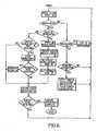
- Figure 6is a flow diagram showing one method of operation of the drug delivery apparatus shown in Figure 3 . It should be appreciated that this method can be applied to other types of nebulizer, and is not limited to operating in connection with an ultrasonic mesh type nebulizer.
- the first stepis for the processor 20 to read the flow rate from the airflow detector 18. If the person has not yet started to inhale, box 62 will return a "NO" and the processor 20 will ask whether or not the aerosol generator 22 is nebulizing. If it is, then the processor 20 will stop the aerosol generator 22 from operating and return to the "START" if it is not nebulizing, then the processor 20 will read the airflow detector 18 to see whether or not the person has started to exhale. If not, it will again return to the "START". If the person has started to exhale, then the processor 20 will store the start of exhalation time for a later pulse length calculation. The details of this calculation will be explained later in the specification. Once this has occurred, the processor 20 will return to the "START".
- the processor 20reads the flow rate 61 from the airflow detector 18, he will found to be inhaling 62, and so the processor will then ask whether or not it is the start of inhalation 67. Since it is the start of inhalation, the processor 20 will then cause the aerosol generator 22 to begin nebulizing 68. It will then update the target breath length 69 based on the previous inhalation data and time between inhalations. This will be explained further later in the specification, but the target breath length is the period of time from commencement of inhalation to the moment the person is signalled to stop inhaling.
- the nebulization timeis set to end, normally sometime before the end of target breath length so that the last part of the air inhaled by the person, and which stays in the upper airways, is not laden with the aerosol which would be wasted. This provides an appropriate aerosol hold time in the region of 1 to 2 seconds without the person needing to hold his or her breath. Calculation of the nebulization time will be described later in this specification. Once it has been done, a running calculation is made of the dose that has been delivered up to that point, which is updated. On the assumption that the target dose has not yet been reached, the processor returns to the "START".
- the flow rate supplied by the airflow detector 18will indicate that the person is still inhaling, and since the last loop through the flow chart indicated that it was the start of inhalation, this time it is not the start of inhalation, and so the processor 20 will then calculate whether or not the end of the nebulization time has been reached. On the assumption that it has not been reached, the running total of the dose delivered is updated, and assuming that the target dose has not yet been reached, the processor 20 returns to the "START". Once the end of the nebulization time has been reached, nebulization will stop, and the processor will then ask whether the feedback time has been reached 75.
- nebulizationis intended to stop before the patient finishes inhaling, typically between 1 and 2 seconds before hand, initially, the feedback time reached box is likely to return a NO.
- the doseis updated in box 72, and the process returns to the START.
- the personis signalled with a feedback signal, and the processor returns to the START.
- the feedback signal to the personis an indication to him to stop inhaling. This signal may be by vibration, audio or visual.
- nebulizationwill stop (box 63/64). The patient will now continue to inhale until the feedback time is reached (box 75).
- the personshould quickly stop inhaling, but is likely to continue to do so for the short period of time it takes him to react. Therefore, the next few circuits through the flow chart by the processor 20 will find that the patient is still inhaling. Once the person does actually stop inhaling, the time taken by the person to stop inhaling from the characterised signal is measured. In addition, the time between inhalations is also measured.
- This processwill be repeated for each breath until the target dose is reached when the nebulizer is switched off and the patient is indicated to stop.
- the nebulizermight also switch itself off. However, the information concerning the target breath length is retained for future operations.
- Figure 7is graph showing the breathing pattern of a person during two inhalations using this apparatus.
- the calculated target inhalation lengthis indicated (T), at the end of which the patient is signalled to exhale.
- T1 on the graph in Figure 7is the time it takes for the person to actually start exhaling. It will be seen from the graph that exhalation is not restricted in the same way as the inhalation phase, and so the flow rate is quite a deep trough.
- the period over which the flow rate is negative, where exhalation is taking place,is indicated as T2. Both of these time periods are measured during the method that was described with reference to Figure 6 .
- the device as described in Figures 3 to 5is used to control the duration of a person's inhalation.
- the duration of inhalationto maximise the aerosol delivery in each inhalation.
- the maximum acceptable inhalation timeis about 9 seconds, or 70-80% of respiratory capacity.
- this part of the breathing manoeuvreis incorporated into the inhalation phase as a period of non-atomisation at the end of the inhalation phase.
- the inhalation flow rateis limited by the airflow regulator 13 to give a maximum inhalation flow of 250 ml per second.
- the respiratory capacity of the personit is preferred just to start at a low inhalation length, adjusting subsequent breath lengths according to how the patient copes with the previous breath. Measuring the inhalation capacity of a person adds complication both in terms of the apparatus and in terms of what the person must do during set-up.
- the target inhalation lengthcan then be carried over to the next treatment. Thus, after the first few treatments, the target inhalation duration would be expected to increase to a level appropriate to that person.
- the adaptive nature of this deviceallows an automatic increase or reduction in the target inhalation length if the patient begins to struggle as a result of exacerbation. The person may be able to reduce the overall treatment time as he or she learns how to maximise the inhalation time.
- the initial target inhalation lengthis set to the minimum value of 3 seconds, which includes the two second aerosol hold period. This means that the aerosol is delivered during the first second of inhalation, and no aerosol is delivered during the second or third second.
- the signalling device 23signals to the patient to exhale, and the time delay between the end of the target inhalation length and the actual start of exhalation is measured. If the delay between the target inhalation length and the actual start of exhalation is greater than a first preset threshold, then the patient may be finding the target inhalation volume too small, and could be expected to cope with an increased inhalation time. If it is less than a second pre-set threshold which may be different to the first threshold, then the patient may be finding the target inhalation volume too large, and this could be reduced.
- the target inhalation lengthcan be adjusted accordingly.
- the first threshold period beyond which the delay between the end of the target inhalation length and the start of exhalation above which the target inhalation length should be increasedis about 0.5 seconds.
- the second threshold beneath which the target inhalation length should be shortenedhas been found to be about 0.3 seconds.
- the first thresholdmay be anywhere in the range of 0.25 to 0.75 seconds, preferably in the range 0.35 to 0.65 seconds and most preferably in the range between 0.45 and 0.55 seconds.
- the second thresholdmay be in the range of -0.2 seconds to 0.5 seconds, preferably between 0 to 0.4 seconds and most preferably between 0.25 and 0.35 seconds.
- the target inhalation length of the following breathwill be increased or decreased as appropriate, typically by not more than 10%, preferably by not more than 5%, most preferably by not more than 2%, but with the optimum change by between 1% and 2%.
- the target inhalation lengthcan be increased or decreased as appropriate, typically by not more than 10%, preferably by not more than 5%, most preferably by not more than 2%, but with the optimum change being between 1 % and 2%.
- the target inhalation lengthis adjusted when the I:E ratio is more than 1, or less than one third, these are only examples of values which have been found appropriate, and this specification is not limited to those values.
- nebulizationoccurs in the form a pulse which, in this case, commences with the detection of the commencement of inhalation and stops before the end of the target inhalation length. Because, in this example, the aerosol hold period has been set to 2 seconds, this means that the nebulization pulse length will be 1 second. However, assuming that the person fmds the target inhalation period of 3 seconds to be too short, this will be extended over the period of a number of breaths, and all of that increase will translate into an increase in the length of the nebulization pulse. The longer the nebulization pulse, the more drugs can be delivered per breath, and the quicker the treatment is completed.
- the target inhalation lengthwas initially set to the minimum value of three seconds, including the two second aerosol hold period (the last two seconds of the inhalation phase).
- the first thresholdwas set at 0.25 seconds and the second threshold was set at -0.05 seconds (i.e. 0.05 seconds before the patient is signalled).
- the second subjecthad a device set with the first threshold at 0.60 seconds and the second threshold set to be 0.3 seconds.
- the third subjecthad a device set with the first threshold of 0.50 seconds, and the second threshold of 0.20 seconds.
- the apparatusadapts to the person's breathing pattern during treatments. This means that the person does not need to attend a clinic to have the treatment regime programmed into the apparatus since the apparatus will make the appropriate adjustments. This is shown in the reduction in treatment times over the first few treatments. This has the benefit of making a significant reduction in the resources required by hospitals and clinics.
- the apparatuscan be used to adapt to a person without delivering any drug during a set up period. This means that before using the device for the delivery of a drug, the person can spend a small number of set up periods familiarising himself with the device and bringing it into a condition where the treatment time will be minimised at the first treatment.
- Figure 10is a flow chart showing how the apparatus is set up, similar to that shown in Figure 6 , but without the delivery of any of the substance to be atomised. The feedback signals are still given at the end of each target inhalation and the target breath length is updated after each breath to take account the time it takes for the patient to stop inhaling.
- the person setting up the devicewill switch the nebulizer on, but will not fill up the reservoir since he is setting up the device rather than receiving a treatment. It may be necessary to switch it to a set-up mode where the empty reservoir does not prevent the set-up process.
- the airflow detector 18Upon commencement of inhalation, the airflow detector 18 will detect the commencement of inhalation, but the electronic control will not allow the ultrasonic transducer 7 to vibrate since the device is being set up and is not delivering a drug to the person.
- the airflow regulator 13operates to regulate the speed of air passing through the passageway 3, thereby lengthening the person's inhalation phase. Once inhalation stops, the airflow detector 18 will detect this.
- the first stepis for the processor to read the flow rate from the airflow detector 18. If the person has not yet started to inhale, the step indicated by the box labelled "Inhaling" will return a "NO" and the processor will then ask whether or not the person has started to exhale. If not, the processor will return to the "START". If the person has started to exhale, then the processor 20 will store the start of exhalation time for a later pulse length calculation.
- the processor 20reads the flow rate from the airflow detector 18, he will be found to be inhaling and so the processor will then ask whether or not it is the start of inhalation. Where it is the start of inhalation, the target breath length will be updated and the feedback time set. The processor then returns to the "START". Since the person has only just begun to inhale, the flow rate supplied by the airflow detector 18 will indicate that the person is still inhaling since the last loop through the flow chart indicated that it was the start inhalation. The processor 20 will then calculate whether or not the target breath length has been reached. Again, assuming that the target breath length has not been reached, the processor 20 returns to the "START". If, however, the end of the target breath length has been reached, the patient is signalled with a feedback signal and the processor returns to the "START". The feedback signal to the person is an indication to him to stop inhaling.
- the personshould quickly stop inhaling, but is likely to continue to do so for the short period of time it takes him to react. Therefore, the next few circuits through the flow chart by the processor 20 will find that the patient is still inhaling. Once the person does actually stop inhaling, the time taken by the person to stop following the feedback signal is measured. In addition, the time between inhalations is also measured.
- the calculations described aboveare carried out to see whether or not the target breath length needs to be changed, and this is updated accordingly when the person starts to inhale on the next breath.
- the nebulizercan be used for treatment, with the target breath length much closer to the optimum breath length.
- the personis benefiting from the set up period in shorter treatment times.
Landscapes
- Health & Medical Sciences (AREA)
- Engineering & Computer Science (AREA)
- Life Sciences & Earth Sciences (AREA)
- Public Health (AREA)
- Anesthesiology (AREA)
- Biomedical Technology (AREA)
- Heart & Thoracic Surgery (AREA)
- Hematology (AREA)
- Bioinformatics & Cheminformatics (AREA)
- Animal Behavior & Ethology (AREA)
- General Health & Medical Sciences (AREA)
- Pulmonology (AREA)
- Veterinary Medicine (AREA)
- Medicinal Preparation (AREA)
- Acyclic And Carbocyclic Compounds In Medicinal Compositions (AREA)
- Medical Preparation Storing Or Oral Administration Devices (AREA)
- Measurement Of The Respiration, Hearing Ability, Form, And Blood Characteristics Of Living Organisms (AREA)
- Control Of Multiple Motors (AREA)
- Measuring And Recording Apparatus For Diagnosis (AREA)
Abstract
Description
- The present invention relates to a drug delivery apparatus.
- A number of devices are available for delivering a drug into the lungs of a patient. A pneumatic or jet type nebulizer is particularly effective in supplying an aerosolized drug for inhalation, but other types of nebulizer are also available, such as ultrasonic type nebulizers in which the drug to be atomized is forced through a mesh by vibration of a piezo-electric crystal, whereupon the droplets passing through the mesh are entrained in the air being inhaled by the patient. The gauge of the mesh determines the size of the droplets which enter the airstream. Electrohydrodynamic (EHD) nebulizers and capillary micro jet nebulizers are also known. Alternatively, a dosimetric spacer can be used. When using a spacer, the drug is introduced into a holding chamber of the spacer, either in areosolized form, or by loading the air within the holding chamber with the drug in powdered form. The patient breathes from the holding chamber thereby inhaling the drug laden air. Such spacers are particularly effective when treating children or elderly patients, and for use with certain drugs. The drug is normally delivered over a number of breaths.
- An example of a mesh type nebulizer is shown in
WO 99/63946 WO 00/38770US 6119953 respectively. - A pneumatic nebulizer is shown in
EP 0627266 A2 in which air from a pressurized air source issues from an air outlet hole around which are disposed holes through which the liquid to be atomized is drawn out from a main reservoir. Each of these holes is within a groove forming a secondary reservoir around the air outlet hole. A deflector bar is located across and in the path of the air issuing from the air outlet so that as it issues from the air outlet, it is immediately deflected across the top of the liquid outlet holes thereby creating low pressure regions drawing the liquid up from the main reservoir beneath, and atomizing that liquid as it is drawn from the holes. The droplets generated in this way are carried to the patient for inhalation. Atomization can be switched on and off by switching on and off the pressurized air supply to the nebulizer. - European patent publication number
0910421 discloses a nebulizer, manufactured under the name Halolite, which delivers a drug during the first half of the patients inhalation in order to maximise lung deposition. The apparatus is interactive in that it measures the duration of a patient's inhalation and calculates a time period that is one half of an average of the patient's duration of inhalation. It is therefore able to match the delivery of the drug with the inhalation profile of the patient and takes account of changes in the patient's inhalation duration over time. It does not require the patient to perform a specific inhalation manoeuvre. - A drug delivery system described in
WO98/52633 - However, the Akita system must first be set up with the patient in a clinic since the system must know the respiratory capacity of the patient in order to indicate the beginning of the breath hold step at the appropriate time. Different patients will have very different respiratory capacities depending on various factors including age, body size and the effect of any respiratory diseases. In addition, the duration of the breath hold must also be customised for particular patients to ensure that the patient will not suffer distress during the use of the system. If the breath hold is too long, then the patient will be unable to continue the treatment over a number breaths without suffering such distress. In addition, as the patient's symptoms change, then the system will need to be reconfigured to take account of this by another visit to a clinic.
- The document
US 5,906,202 discloses a device and method for directing an aerosol mist to a specific area of the respiration tract involving the use of a hand held metered dose inhaler which, when the patient begins to inhale, releases an aerosolized drug once a pre-set measured volume of air has been inhaled. Once a further pre-set volume of air has been inhaled, the device either prevents further inhalation or signals to the patient to stop inhalation whereupon the patient holds his breath for a given period of time after which the patient is indicated to continue with normal breathing. The documentUS 5,906,202 discloses a drug delivery apparatus according to the preamble ofclaim 1. - According to the present invention, there is provided a drug delivery apparatus as defined in
claim 1. - The drug delivery apparatus preferably includes an airflow regulator for restricting the speed of the inhaled airstream through the device.
- The signalling device may be any one or more of an audio device, a visual device and a vibrator device. The audio device might emit a tone or a buzz. The visual device may include a screen, such as an LCD screen, or simple lights, possibly in the form of LED's. The vibrator device can signal to the person by causing the apparatus to vibrate thereby signalling to the person to stop inhaling.
- In addition, the controller preferably includes a calculator arranged to calculate the pre-set period of time. The controller may be formed using a microprocessor.
- A method of generating signals in a drug delivery apparatus through which a person inhales to generate an inhaled airstream is also described and does not form part of the present invention. Said method comprises the steps of detecting the commencement of inhalation, signalling to the person to cease inhalation after a pre-set period of time has elapsed from the detection of the commencement of breathing, and adjusting the pre-set period of time for subsequent inhalations depending on the time the person takes to stop inhaling after being signalled.
- In order to be responsive to the person using the drug delivery apparatus, the pre-set period of time may be increased if the time taken to stop inhaling exceeds a first threshold time, and may be decreased if the time taken to stop inhaling is less than a second threshold time. The first threshold time is normally greater than or equal to the second threshold time. The first threshold time is preferably about 0.5 seconds. The first threshold time may be in the range of 0.25 to 0.75 seconds, preferably in the range of 0.35 to 0.65 seconds, and most preferably in the range 0.45 to 0.55 seconds.
- The second threshold time is preferably is about 0.3 seconds. It may be in the range of minus 0.2 to 0.5 seconds, preferably 0 to 0.4 seconds and most preferably 0.25 to 0.35 seconds.
- The method preferably further comprises the steps of detecting the end of inhalation and calculating the period of inhalation and the period of exhalation. This then allows all of the calculations necessary to be made. The method may include the step of calculating the inhalation to exhalation (I:E) ratio, and if it is greater than a third threshold, increasing the preset period of time. In this case, the third threshold of time is preferably about 1. The method may also include the step of calculating the I:E ratio, and if it is less than a fourth threshold, the preset period of time can be decreased. In this case, the fourth threshold of time is preferably about one third.
- It will be appreciated that the drug delivery apparatus can be set up using the above mentioned method before it is used to deliver a drug. Alternatively, it can be done at the same time, whereby an aerosolized substance is delivered into at least a part of the inhaled air stream. Aerosol delivery is normally ceased before signalling to the person to cease inhalation. The aerosol delivery is ceased preferably at least one second before signalling to the person, and most preferably at least two seconds before signalling to the person.
- The time taken for the person to stop inhaling in response to the signal has been found to be a good indication of whether or not the patient is experiencing distress, and so the pre-set period of time can be adjusted to accommodate the patient concerned and his particular requirements. This can be done without needing to visit a clinic. For example, if the person takes a relatively long time to stop inhaling, that is an indication that the pre-set period of time following the detection of the commencement or breathing can be lengthened. Conversely, if a person ceases to inhale very quickly after he is signalled to do so, or if he stops inhaling before signalled to stop, that will be an indication that the duration of the pre-set period of time is too long. The pre-set period can then be adjusted accordingly.
- The invention will now be described by way of example only with reference to the drawings in which:
Figure 1 is a graph in which the total residence time of a drug within the lungs is plotted against the percentage of the drug which is deposited within the lungs;Figure 2 is a graph plotting the aerosol hold/breath hold time against exhaled filter fraction;Figure 3 is a schematic drawing showing a drug delivery apparatus according to a preferred embodiment of the present invention;Figure 4 is a perspective view of an airflow regulator of the drug delivery apparatus ofFigure 3 ;Figure 5 is a block diagram showing how the drug delivery apparatus is controlled, and how the patient is signalled in the drug delivery apparatus ofFigure 3 ;Figure 6 is flow diagram showing a method of operation of the drug delivery apparatus during which both drug delivery occurs and adjustment of the device to take account of the patient's breathing pattern occurs;Figure 7 is a graph showing the breathing pattern of a patient using the device ofFigure 3 , with flow rate plotted against time;Figure 8 is a graph showing the target inhalation length plotted against the number of treatments carried out by three subjects;Figure 9 is a graph showing the treatment time plotted against the number of treatments for each of the three subjects;Figure 10 is a flow diagram showing a second method of operation of the device ofFigure 3 in which the operation of the device is optimised for a person prior to drug delivery.- The Akita and Halolite system described in the introductory part of this application were used in an experiment in which a patient was supplied with a radio labelled aerosol. The aerosol was radio labelled to allow scintigraphic evaluation of the experiment. The systems were used in accordance with the manufacturers recommendations. A Sidestream nebulizer (Profile Respiratory Systems Ltd, Bognor Regis UK) and a nose clip were used. The Akita system provided a positive pressure stream of air for inhalation at 15 litres per minute up to a volume equivalent to 80% of respiratory capacity with a breath hold of between 5 and 9 seconds. A computer screen provided feedback to the patient as to the duration of inhalation and the breath holding pause required. In the case of the Akita System, on commencement of inhalation, the computer screen displays a numerical countdown of the period over which the patient should inhale. At the end of that period of time, the person must hold his breath while the computer screen displays a further countdown of time until the patient is permitted to exhale. In the case of the Halolite System, the patient breathes in and out naturally without any feedback indicating to the person when to start inhaling, stop inhaling or carry out a breath hold. In fact, with the Halolite, since the person is intended to breathe in a slow relaxed manner, there will not be any breath hold period. However, since the atomisation stops before the end of the breath, there is a period of time during which the patient is still inhaling, but no aerosol is reaching the person's lungs. This period of time is referred to in this specification as the "aerosol hold time". This contrasts with the Akita System in which atomisation occurs during the entire inhalation phase, and only stops once the patient begins his breath hold. Therefore, the aerosol hold time and the breath hold time are rather different, but have the same effect of defining a minimum period during which the aerosol is resident within the lung. After the breath hold the subject exhales through a filter in order to trap any of the aerosol.
- A treatment time of between 5 and 12 minutes was needed to deliver a set dose of 0.4ml of Tc-DTPA from a 2.5ml nebulizer fill.
- A scintigraphic evaluation of the patients was carried out in order to identify how much of the radio labelled aerosol remained in the lungs of the patients. The results from both systems were analysed with respect to the patients breathing parameters. The results of the experiment are shown in
Figures 1 and2 . InFigure 1 , the total residence time of the drug within the lungs is plotted against the total lung deposition as a percentage of the total aerosol delivered. It will be seen clearly that lung deposition increases with the total residence time. For example, a total residence time of 2 seconds is likely to result in less than 30% of the aerosol being deposited in the lungs, whereas doubling the residence time to 4 seconds will typically give a total lung deposition of more than 40%. By the time the total residence time reaches 12 seconds, the lung deposition reaches about two thirds of the aerosol delivered.. Figure 2 is a graph in which the aerosol hold time (Halolite System) and breath hold time (Akita System) is plotted against the exhaled filter fraction. The exhaled fraction is reduced with increasing aerosol hold time. It indicated that for a aerosol hold time in the order of 1 second exhaled losses are in the region of 15-20% but if the aerosol hold time is increased to 2 seconds the losses are reduced to 10%. Increasing the aerosol hold time allows more time for the aerosol to deposit in the lung, as the principal method of deposition for particles of this size is sedimentation, which is time dependent.- The overall conclusion of this experiment is that the longer the aerosol is resident within the lungs, the higher the total lung deposition. This can be achieved both by the patient holding his breath following inhalation, and also by increasing the total inhalation time of the patient.
- Referring now to
Figure 3 , a drug delivery apparatus is shown which is amesh type nebulizer 1 for generating an aerosol indicated generally at 2 in apassageway 3. Thepassageway 3 has aninlet 4 through which air enters it, and at itsopposite end 5 the air passing through thepassageway 3 is led to a mouthpiece or the like (not shown). During operation of thenebulizer 1, theaerosol 2 is entrained in the airflow leading to the mouthpiece. Nebulization takes place by a drug being forced through amesh plate 6 by using anultrasonic transducer 7 which drives ahorn 8 to vibrate in the region of themesh plate 6. Thehorn 8 is located close to the rear face of themesh plate 6 and is caused to vibrate by theultrasonic transducer 7, whereby theaerosol 2 is generated from the front face of themesh plate 6. The substance to be atomised into anaerosol 2 is in fluid contact with the rear face of themesh plate 6 and it is this that is driven through the holes of themesh plate 6 by the vibratinghorn 8. - During each treatment, a certain volume of the substance to be atomised is located in a
reservoir 9 which is located above themesh plate 6 in which to feed the substance to be atomised to its rear face. Afluid sensor 10 is located between thereservoir 9 and themesh plate 6 such that once the substance to be atomised has substantially all been aerosolized, this is detected so that theultrasonic transducer 7 may be switched off at the end of treatment. - A
power supply 11 is used to power the atomiser since power is required to drive aerosolization. Anelectronic controller 12 controls theultrasonic transducer 7 so that, for example, once thefluid sensor 10 senses that there is no liquid remaining to be atomised, theultrasonic transducer 7 will be switched off. In addition, a more sophisticated control device can be used here such that the patient's breathing is measured, and atomisation only occurs during the inhalation part of a patient's breathing pattern. - An
airflow regulator 13 is located in thepassageway 3. This is shown in more detail inFigure 4 from which it will be seen that theregulator 13 includes aframe 14 having an interior edge 15 (shown in dotted lines) which defines an aperture through which air must pass if it is to enter thepassageway 3. A resilient flap 16 is located in front of the aperture located in theframe 14, and arib 17 lying on theframe 14 acts as a spacer to prevent the flap 16 from completely closing the aperture. The flap 16 is typically made of a resilient silicone material. This means that any airflow through theregulator 13 which passes through the aperture and then against the flap 16 will cause the flap 16 to be deflected away from theframe 14 allowing the air to pass relatively freely. However, airflow passing the opposite way will cause the flap 16 to close, and the aperture will be severely restricted allowing a limited airflow to pass. The resilient nature of the flap will tend to offer more resistance to the airflow the greater the pressure difference on the opposite sides of theframe 14. This airflow regulator, therefore, limits the rate at which air passes through thepassageway 3 towards the mouthpiece. - The nebulizer also includes an
airflow detector 18 which is able to measure both the direction of airflow through thepassageway 3 and the velocity of the airflow. In this embodiment, it is indicated to be located within thepassageway 3, but could be located in various other positions, even in the mouthpiece. Thedetector 18 may be any one of a variety of different types of detector, such as a temperature sensor, a pressure sensor, a microphone type sensor or a mechanical sensor which is deflected by the airflow. The type of sensor used is not an important factor in this invention. - The basic operation of this nebulizer will now be described. Firstly, the patient will pour a certain volume of the substance to be atomised into the
reservoir 9. Thereservoir 9 may be sized such that it will exactly hold the appropriate volume of the substance that is required. The patient can then begin to breathe in and out through the mouthpiece. Upon commencement of inhalation, theairflow detector 18 will detect the commencement of inhalation, and theelectronic control 12 will cause theultrasonic transducer 7 to vibrate, thereby driving thehorn 8 to cause aerosolization of the substance to be atomised. As the substance is aerosolized, thereservoir 9 empties, and once the level of the substance drops below thefluid sensor 10, theelectronic control 12 switches off the ultrasonic transducer. - During inhalation, the
airflow regulator 13 operates to regulate the speed of air passing through thepassageway 3 and to the patient, thereby lengthening the patient's inhalation phase. Once the patient stops inhaling, theairflow detector 18 will detect this, and will cause theelectronic control 12 to stop theultrasonic transducer 7 driving thehorn 8 until the next inhalation phase is detected. Alternatively, theelectronic control 12 might be arranged only to drive the ultrasonic transducer during, say, the first 50% of the inhalation phase of the patient. To achieve this, the duration of inhalation of the previous few inhalations as measured by theairflow detector 18 will need to be averaged, and half of this averaged duration will be the period for which theelectronic control 12 causes theultrasonic transducer 7 to drive thehorn 8 to atomise the substance. Of course, it will be appreciated that atomisation might occur during 60%, 70%, 80% or any other suitable proportion of the inhalation phase. - During exhalation, the exhaled air might be exhausted from an outlet in the mouthpiece, or alternatively might flow back up the
passageway 3 towards theairflow regulator 13 which will open to allow the air to be exhausted freely. It is preferable to locate theairflow detector 18 as close to the mouthpiece as possible, and where the exhaled air is exhausted from an outlet in the mouthpiece, it will normally be appropriate to locate theairflow detector 18 within the mouthpiece. - Also, the
airflow regulator 13 may be located anywhere in the device where it will restrict the airflow leading to the patient. However, it is preferred that it is located upstream of the point at which the aerosol is generated during inhalation. That way, the aerosol will not be removed from the airstream by the constriction caused by theairflow regulator 13. Figure 5 shows the arrangement of the nebulizer in block diagram form. From it, one block refers to theairflow detector 18 shown inFigure 3 . The output from thedetector 18 is passed to aprocessor 20 which controls theaerosol generator 22 and a patient signalling device 23. Theprocessor 20 will include theelectronic control 12 shown inFigure 3 , as well as other elements. Theaerosol generator 22 refers to a combination of themesh plate 6, theultrasonic transducer 7, thehorn 8 and thereservoir 9 in thenebulizer 1 shown inFigure 3 . The patient signalling device 23 is not shown inFigure 3 , but is some form of device which generates signals for the patient when to carry out certain breathing manoeuvres. According to one arrangement, this could be a vibrator device which causes thenebulizer 1 to gently vibrate to signal when to carry out particular manoeuvres. Alternatively, it can be an audio device which uses sounds to signal to the patient when to carry out the manoeuvres. It could even be a visual device where the patient is signalled to carry out particular manoeuvres on the basis of visual signals which may be lights or an LCD screen. The signalling device 23 could be a combination of these systems. The operation of the blocks shown inFigure 5 will become clearer when the overall operation of the device is described with reference toFigure 6 .Figure 6 is a flow diagram showing one method of operation of the drug delivery apparatus shown inFigure 3 . It should be appreciated that this method can be applied to other types of nebulizer, and is not limited to operating in connection with an ultrasonic mesh type nebulizer.- The first step is for the
processor 20 to read the flow rate from theairflow detector 18. If the person has not yet started to inhale,box 62 will return a "NO" and theprocessor 20 will ask whether or not theaerosol generator 22 is nebulizing. If it is, then theprocessor 20 will stop theaerosol generator 22 from operating and return to the "START" if it is not nebulizing, then theprocessor 20 will read theairflow detector 18 to see whether or not the person has started to exhale. If not, it will again return to the "START". If the person has started to exhale, then theprocessor 20 will store the start of exhalation time for a later pulse length calculation. The details of this calculation will be explained later in the specification. Once this has occurred, theprocessor 20 will return to the "START". - Once the person starts inhaling, when the
processor 20 reads theflow rate 61 from theairflow detector 18, he will found to be inhaling 62, and so the processor will then ask whether or not it is the start ofinhalation 67. Since it is the start of inhalation, theprocessor 20 will then cause theaerosol generator 22 to begin nebulizing 68. It will then update thetarget breath length 69 based on the previous inhalation data and time between inhalations. This will be explained further later in the specification, but the target breath length is the period of time from commencement of inhalation to the moment the person is signalled to stop inhaling. Once the target breath length has been updated, the nebulization time is set to end, normally sometime before the end of target breath length so that the last part of the air inhaled by the person, and which stays in the upper airways, is not laden with the aerosol which would be wasted. This provides an appropriate aerosol hold time in the region of 1 to 2 seconds without the person needing to hold his or her breath. Calculation of the nebulization time will be described later in this specification. Once it has been done, a running calculation is made of the dose that has been delivered up to that point, which is updated. On the assumption that the target dose has not yet been reached, the processor returns to the "START". Since the patient has only just began to inhale, the flow rate supplied by theairflow detector 18 will indicate that the person is still inhaling, and since the last loop through the flow chart indicated that it was the start of inhalation, this time it is not the start of inhalation, and so theprocessor 20 will then calculate whether or not the end of the nebulization time has been reached. On the assumption that it has not been reached, the running total of the dose delivered is updated, and assuming that the target dose has not yet been reached, theprocessor 20 returns to the "START". Once the end of the nebulization time has been reached, nebulization will stop, and the processor will then ask whether the feedback time has been reached 75. Since nebulization is intended to stop before the patient finishes inhaling, typically between 1 and 2 seconds before hand, initially, the feedback time reached box is likely to return a NO. The dose is updated inbox 72, and the process returns to the START. Once the feedback time has been reached, then the person is signalled with a feedback signal, and the processor returns to the START. The feedback signal to the person is an indication to him to stop inhaling. This signal may be by vibration, audio or visual. In the unlikely event the patient exhaled before the end of nebulization time is reached, nebulization will stop (box 63/64). The patient will now continue to inhale until the feedback time is reached (box 75). - Once the feedback signal is produced by the signalling device 23, the person should quickly stop inhaling, but is likely to continue to do so for the short period of time it takes him to react. Therefore, the next few circuits through the flow chart by the
processor 20 will find that the patient is still inhaling. Once the person does actually stop inhaling, the time taken by the person to stop inhaling from the characterised signal is measured. In addition, the time between inhalations is also measured. - This process will be repeated for each breath until the target dose is reached when the nebulizer is switched off and the patient is indicated to stop. The nebulizer might also switch itself off. However, the information concerning the target breath length is retained for future operations.
Figure 7 is graph showing the breathing pattern of a person during two inhalations using this apparatus. During inhalation, because of theairflow regulator 13, the inhalation flow is limited and therefore the graph shows a flat top to the inhalation phase. The calculated target inhalation length is indicated (T), at the end of which the patient is signalled to exhale. The period of time labelled T1 on the graph inFigure 7 is the time it takes for the person to actually start exhaling. It will be seen from the graph that exhalation is not restricted in the same way as the inhalation phase, and so the flow rate is quite a deep trough. The period over which the flow rate is negative, where exhalation is taking place, is indicated as T2. Both of these time periods are measured during the method that was described with reference toFigure 6 .- Some testing of the invention has taken place to establish how long T1 and T2 should normally be, and when the target inhalation length should be changed, and by how much.
- In this example, the device as described in
Figures 3 to 5 is used to control the duration of a person's inhalation. The duration of inhalation to maximise the aerosol delivery in each inhalation. In practice, the maximum acceptable inhalation time is about 9 seconds, or 70-80% of respiratory capacity. Instead of a breath hold period of two seconds, this part of the breathing manoeuvre is incorporated into the inhalation phase as a period of non-atomisation at the end of the inhalation phase. The inhalation flow rate is limited by theairflow regulator 13 to give a maximum inhalation flow of 250 ml per second. - Although it is possible to measure the respiratory capacity of the person, it is preferred just to start at a low inhalation length, adjusting subsequent breath lengths according to how the patient copes with the previous breath. Measuring the inhalation capacity of a person adds complication both in terms of the apparatus and in terms of what the person must do during set-up. The target inhalation length can then be carried over to the next treatment. Thus, after the first few treatments, the target inhalation duration would be expected to increase to a level appropriate to that person. The adaptive nature of this device allows an automatic increase or reduction in the target inhalation length if the patient begins to struggle as a result of exacerbation. The person may be able to reduce the overall treatment time as he or she learns how to maximise the inhalation time.
- In this example, the initial target inhalation length is set to the minimum value of 3 seconds, which includes the two second aerosol hold period. This means that the aerosol is delivered during the first second of inhalation, and no aerosol is delivered during the second or third second. At the end of the three second period, the signalling device 23 signals to the patient to exhale, and the time delay between the end of the target inhalation length and the actual start of exhalation is measured. If the delay between the target inhalation length and the actual start of exhalation is greater than a first preset threshold, then the patient may be finding the target inhalation volume too small, and could be expected to cope with an increased inhalation time. If it is less than a second pre-set threshold which may be different to the first threshold, then the patient may be finding the target inhalation volume too large, and this could be reduced.
- In addition, if the time between inhalations is shorter than the last inhalation time (for example if I:E is more than one) then the patient may be desperate to reach the next inhalation, suggesting the target inhalation length is not long enough. If the time between inhalations exceeds 3 times the inhalation time then it is assumed that the patient needs to take a rest between inhalations and the target inhalation length is too long. The target inhalation length can be adjusted accordingly.
- During experiments, it has been found that the first threshold period beyond which the delay between the end of the target inhalation length and the start of exhalation above which the target inhalation length should be increased is about 0.5 seconds. The second threshold beneath which the target inhalation length should be shortened has been found to be about 0.3 seconds. The first threshold may be anywhere in the range of 0.25 to 0.75 seconds, preferably in the range 0.35 to 0.65 seconds and most preferably in the range between 0.45 and 0.55 seconds. The second threshold may be in the range of -0.2 seconds to 0.5 seconds, preferably between 0 to 0.4 seconds and most preferably between 0.25 and 0.35 seconds.
- Where the delay between the target inhalation length and the start of exhalation falls outside of the thresholds, the target inhalation length of the following breath will be increased or decreased as appropriate, typically by not more than 10%, preferably by not more than 5%, most preferably by not more than 2%, but with the optimum change by between 1% and 2%.
- Where the I:E is calculated to be outside of the normal range, for example if it is more than one or less than one third, the target inhalation length can be increased or decreased as appropriate, typically by not more than 10%, preferably by not more than 5%, most preferably by not more than 2%, but with the optimum change being between 1 % and 2%. Of course, although in this example, the target inhalation length is adjusted when the I:E ratio is more than 1, or less than one third, these are only examples of values which have been found appropriate, and this specification is not limited to those values.
- Reference is made above to the setting of the nebulization time which is set during the method described with reference to
Figure 6 . To expand this further, it should be understood that nebulization occurs in the form a pulse which, in this case, commences with the detection of the commencement of inhalation and stops before the end of the target inhalation length. Because, in this example, the aerosol hold period has been set to 2 seconds, this means that the nebulization pulse length will be 1 second. However, assuming that the person fmds the target inhalation period of 3 seconds to be too short, this will be extended over the period of a number of breaths, and all of that increase will translate into an increase in the length of the nebulization pulse. The longer the nebulization pulse, the more drugs can be delivered per breath, and the quicker the treatment is completed. - In an experiment, three people were subjected to a regimen where the various thresholds described above were different. Three subjects were given ten consecutive treatments using the device. For each of them, the target inhalation length was initially set to the minimum value of three seconds, including the two second aerosol hold period (the last two seconds of the inhalation phase). For the first subject, the first threshold was set at 0.25 seconds and the second threshold was set at -0.05 seconds (i.e. 0.05 seconds before the patient is signalled). The second subject had a device set with the first threshold at 0.60 seconds and the second threshold set to be 0.3 seconds. The third subject had a device set with the first threshold of 0.50 seconds, and the second threshold of 0.20 seconds.
- The results are plotted in
Figures 8 and9 . It will be seen fromFigure 8 thatsubject 1 reached the maximum target inhalation length of 9 seconds within 5 treatments. All three subjects reached the target inhalation length within 10 treatments, and it will be seen that the target inhalation length adapts from treatment to treatment to take account of the symptoms of a patient. It will also be seen fromFigure 9 that the duration of each treatment drops significantly as the target inhalation lengths increase. Patients tend to comply with treatments much better when the treatment times are short. These three patients reached 70, 76, 112% of their respiratory capacity, indication that the system is very effective at maximising aerosol delivery without having to make separate measurements of respiratory capacity and programming these into the device. - In these examples of the use of the apparatus shown in
Figures 3 and 4 , the apparatus adapts to the person's breathing pattern during treatments. This means that the person does not need to attend a clinic to have the treatment regime programmed into the apparatus since the apparatus will make the appropriate adjustments. This is shown in the reduction in treatment times over the first few treatments. This has the benefit of making a significant reduction in the resources required by hospitals and clinics. - The apparatus can be used to adapt to a person without delivering any drug during a set up period. This means that before using the device for the delivery of a drug, the person can spend a small number of set up periods familiarising himself with the device and bringing it into a condition where the treatment time will be minimised at the first treatment.
Figure 10 is a flow chart showing how the apparatus is set up, similar to that shown inFigure 6 , but without the delivery of any of the substance to be atomised. The feedback signals are still given at the end of each target inhalation and the target breath length is updated after each breath to take account the time it takes for the patient to stop inhaling. - Firstly, the person setting up the device will switch the nebulizer on, but will not fill up the reservoir since he is setting up the device rather than receiving a treatment. It may be necessary to switch it to a set-up mode where the empty reservoir does not prevent the set-up process. Upon commencement of inhalation, the
airflow detector 18 will detect the commencement of inhalation, but the electronic control will not allow theultrasonic transducer 7 to vibrate since the device is being set up and is not delivering a drug to the person. During inhalation, theairflow regulator 13 operates to regulate the speed of air passing through thepassageway 3, thereby lengthening the person's inhalation phase. Once inhalation stops, theairflow detector 18 will detect this. - From the flow chart of
Figure 10 , the first step is for the processor to read the flow rate from theairflow detector 18. If the person has not yet started to inhale, the step indicated by the box labelled "Inhaling" will return a "NO" and the processor will then ask whether or not the person has started to exhale. If not, the processor will return to the "START". If the person has started to exhale, then theprocessor 20 will store the start of exhalation time for a later pulse length calculation. - Once the person starts inhaling, when the
processor 20 reads the flow rate from theairflow detector 18, he will be found to be inhaling and so the processor will then ask whether or not it is the start of inhalation. Where it is the start of inhalation, the target breath length will be updated and the feedback time set. The processor then returns to the "START". Since the person has only just begun to inhale, the flow rate supplied by theairflow detector 18 will indicate that the person is still inhaling since the last loop through the flow chart indicated that it was the start inhalation. Theprocessor 20 will then calculate whether or not the target breath length has been reached. Again, assuming that the target breath length has not been reached, theprocessor 20 returns to the "START". If, however, the end of the target breath length has been reached, the patient is signalled with a feedback signal and the processor returns to the "START". The feedback signal to the person is an indication to him to stop inhaling. - Once the feedback signal is produced by the signalling device 23, the person should quickly stop inhaling, but is likely to continue to do so for the short period of time it takes him to react. Therefore, the next few circuits through the flow chart by the
processor 20 will find that the patient is still inhaling. Once the person does actually stop inhaling, the time taken by the person to stop following the feedback signal is measured. In addition, the time between inhalations is also measured. - The calculations described above are carried out to see whether or not the target breath length needs to be changed, and this is updated accordingly when the person starts to inhale on the next breath. After a number of set up operations, the nebulizer can be used for treatment, with the target breath length much closer to the optimum breath length. Thus, from the very first delivery of a drug, the person is benefiting from the set up period in shorter treatment times.
- It will be appreciated that, although a mesh type nebulizer is used in the device shown in
Figures 3 to 5 , other types of nebulizer may be equally appropriate. What is important is the adaptation of the target inhalation length to the patient's actual breathing pattern.
Claims (17)
- Drug delivery apparatus (1) arranged to deliver aerosolized drug into an inhaled airstream of a person comprising:an airflow sensor (18) for detecting the inhaled airstream;a signalling device (23) arranged to give signals to the person; anda controller (12,20) arranged to control the operation of the signalling device (23) on the basis of the inhaled airstream detected by the flow sensor (18), whereby the controller (12,20) is arranged to cause the signalling device (23) to signal to the person to cease inhalation,characterised in that the controller (12,20) is arranged to cause the signalling device (23) to signal to the person to cease inhalation after a pre-set period of time following the detection of inhalation, and to adjust the pre-set period of time for subsequent inhalations depending on the time the person takes to stop inhaling after being signalled.
- An apparatus according to claim 1, further comprising an airflow regulator (13) for restricting the speed of the inhaled airstream through the apparatus (1).
- An apparatus according to claim 1, further comprising an aerosol generator for aerosolizing the drug into the inhaled airstream.
- An apparatus according to any one of claims 1 to 3, wherein the signalling device (23) is any one or more of: an audio device, a visual device and a vibrator device.
- An apparatus according to any one of claims 1 to 4, wherein the controller (12,20) includes a calculator arranged to calculate the pre-set period of time.
- An apparatus according to any one of claims 1 to 5, wherein the controller (12,20) is formed by a microprocessor.
- Apparatus according to any one of the preceding claims, wherein the pre-set period of time is increased if the time taken to stop inhaling exceeds a first threshold time.
- Apparatus according to claim 7, wherein the pre-set period of time is decreased if the time taken to stop inhaling is less than a second threshold time.
- Apparatus according to claim 8, wherein the first threshold time is greater than or equal to the second threshold time.
- Apparatus according to any one of claims 7 to 9, wherein the first threshold time is about 0.5 seconds.
- Apparatus according to claim 10, wherein the first threshold time is in the range of 0.25 to 0.75 seconds.
- Apparatus according to claim 10, wherein the first threshold time is in the range of 0.35 to 0.65 seconds.
- Apparatus according to claim 10, wherein the first threshold time is in the range of 0.45 to 0.55 seconds.
- Apparatus according to any one of claims 8 to 13, wherein the second threshold time is about 0.3 seconds.
- Apparatus according to claim 14, wherein the second threshold time is in the range of -0.2 to 0.5 seconds.
- Apparatus according to claim 14, wherein the second threshold time is in the range of 0 to 0.4 seconds.
- Apparatus according to claim 14, wherein the second threshold time is in the range of 0.25 to 0.35 seconds.
Priority Applications (1)
| Application Number | Priority Date | Filing Date | Title |
|---|---|---|---|
| EP09000341AEP2047881B1 (en) | 2002-11-20 | 2003-11-20 | Method for setting up a drug delivery apparatus |
Applications Claiming Priority (3)
| Application Number | Priority Date | Filing Date | Title |
|---|---|---|---|
| GB0227105 | 2002-11-20 | ||
| GB0227105AGB2395437C (en) | 2002-11-20 | 2002-11-20 | Improved inhalation method and apparatus |
| PCT/GB2003/005048WO2004045689A1 (en) | 2002-11-20 | 2003-11-20 | Improved inhalation method and apparatus |
Related Child Applications (1)
| Application Number | Title | Priority Date | Filing Date |
|---|---|---|---|
| EP09000341ADivisionEP2047881B1 (en) | 2002-11-20 | 2003-11-20 | Method for setting up a drug delivery apparatus |
Publications (2)
| Publication Number | Publication Date |
|---|---|
| EP1581291A1 EP1581291A1 (en) | 2005-10-05 |
| EP1581291B1true EP1581291B1 (en) | 2009-01-14 |
Family
ID=9948206
Family Applications (2)
| Application Number | Title | Priority Date | Filing Date |
|---|---|---|---|
| EP09000341AExpired - LifetimeEP2047881B1 (en) | 2002-11-20 | 2003-11-20 | Method for setting up a drug delivery apparatus |
| EP03777000AExpired - LifetimeEP1581291B1 (en) | 2002-11-20 | 2003-11-20 | Drug delivery apparatus |
Family Applications Before (1)
| Application Number | Title | Priority Date | Filing Date |
|---|---|---|---|
| EP09000341AExpired - LifetimeEP2047881B1 (en) | 2002-11-20 | 2003-11-20 | Method for setting up a drug delivery apparatus |
Country Status (10)
| Country | Link |
|---|---|
| US (1) | US7748382B2 (en) |
| EP (2) | EP2047881B1 (en) |
| JP (1) | JP4549189B2 (en) |
| AT (2) | ATE476211T1 (en) |
| AU (1) | AU2003286257B2 (en) |
| BR (1) | BRPI0316444B8 (en) |
| CA (1) | CA2506452C (en) |
| DE (2) | DE60325897D1 (en) |
| GB (1) | GB2395437C (en) |
| WO (1) | WO2004045689A1 (en) |
Cited By (5)
| Publication number | Priority date | Publication date | Assignee | Title |
|---|---|---|---|---|
| US8439033B2 (en) | 2007-10-09 | 2013-05-14 | Microdose Therapeutx, Inc. | Inhalation device |
| US8985101B2 (en) | 2009-05-21 | 2015-03-24 | Microdose Therapeutx, Inc. | Method and device for clamping a blister within a dry powder inhaler |
| US8991390B2 (en) | 2010-01-05 | 2015-03-31 | Microdose Therapeutx, Inc. | Inhalation device and method |
| US10238821B2 (en) | 2016-10-11 | 2019-03-26 | Microdose Therapeutx, Inc. | Inhaler and methods of use thereof |
| US12128174B1 (en) | 2016-05-27 | 2024-10-29 | Proveris Scientific Corporation | Devices and methods for using medicament devices |
Families Citing this family (75)
| Publication number | Priority date | Publication date | Assignee | Title |
|---|---|---|---|---|
| US7080644B2 (en)* | 2000-06-28 | 2006-07-25 | Microdose Technologies, Inc. | Packaging and delivery of pharmaceuticals and drugs |
| CA2554005C (en) | 2004-02-24 | 2013-05-28 | Microdose Technologies, Inc. | Directional flow sensor inhaler |
| GB0422413D0 (en)* | 2004-10-08 | 2004-11-10 | Breath Ltd | High efficiency nebulisation |
| EP2037999B1 (en) | 2006-07-07 | 2016-12-28 | Proteus Digital Health, Inc. | Smart parenteral administration system |
| FR2908329B1 (en) | 2006-11-14 | 2011-01-07 | Telemaq | DEVICE AND METHOD FOR ULTRASOUND FLUID DELIVERY |
| US8371299B2 (en)* | 2007-04-19 | 2013-02-12 | Respironics Respiratory Drug Delivery | Ventilator aerosol delivery |
| US8415390B2 (en) | 2008-05-30 | 2013-04-09 | Microdose Therapeutx, Inc. | Methods and compositions for administration of oxybutynin |
| US9119777B2 (en) | 2008-05-30 | 2015-09-01 | Microdose Therapeutx, Inc. | Methods and compositions for administration of oxybutynin |
| JP2010529894A (en) | 2007-06-15 | 2010-09-02 | スパンドーファー,マイケル | Drug delivery and monitoring system for ventilators |
| US8875697B2 (en)* | 2007-07-24 | 2014-11-04 | Ric Investments, Llc | Drug delivery apparatus and method |
| US9125979B2 (en) | 2007-10-25 | 2015-09-08 | Proteus Digital Health, Inc. | Fluid transfer port information system |
| US8419638B2 (en) | 2007-11-19 | 2013-04-16 | Proteus Digital Health, Inc. | Body-associated fluid transport structure evaluation devices |
| CA2709071C (en) | 2007-12-14 | 2016-11-15 | Labogroup S.A.S. | Delivering aerosolizable food products |
| US8371294B2 (en)* | 2008-02-29 | 2013-02-12 | Microdose Therapeutx, Inc. | Method and apparatus for driving a transducer of an inhalation device |
| EP2119465A1 (en)* | 2008-05-16 | 2009-11-18 | Markos Mefar S.P.A. | Nebulizer with breathing phase detecting sensor for delivering nebulized drugs to a user |
| BRPI0912918B8 (en)* | 2008-08-25 | 2021-06-22 | Koninklijke Philips Electronics Nv | respiratory drug delivery device, and method of encouraging the use of a respiratory drug delivery device |
| BRPI1011194A2 (en)* | 2009-05-21 | 2016-12-27 | Microdose Therapeutx Inc | rotary dry powder inhaler receptacle system |
| JP5410157B2 (en)* | 2009-05-22 | 2014-02-05 | 株式会社カネカ | Polypropylene resin in-mold foam molding |
| US20110000481A1 (en)* | 2009-07-01 | 2011-01-06 | Anand Gumaste | Nebulizer for infants and respiratory compromised patients |
| JP5927118B2 (en)* | 2009-08-15 | 2016-05-25 | コーニンクレッカ フィリップス エヌ ヴェKoninklijke Philips N.V. | System and method for remotely monitoring and / or managing treatment of multiple subjects using nebulized medication |
| JP2013501565A (en) | 2009-08-15 | 2013-01-17 | コーニンクレッカ フィリップス エレクトロニクス エヌ ヴィ | System and method for enabling therapeutic delivery of aerosolized drugs to multiple subjects to be monitored |
| JP5734992B2 (en) | 2009-11-11 | 2015-06-17 | コーニンクレッカ フィリップス エヌ ヴェ | Medicine delivery apparatus and method |
| CN101850145A (en)* | 2009-11-21 | 2010-10-06 | 王丹琳 | Medical atomizer with breath synchronization |
| US10857311B2 (en) | 2010-01-12 | 2020-12-08 | Omega Life Science Ltd. | Method and apparatus for producing fine concentrated aerosol |
| BR112012019212A2 (en) | 2010-02-01 | 2017-06-13 | Proteus Digital Health Inc | data collection system |
| EP2531096A4 (en) | 2010-02-01 | 2013-09-11 | Proteus Digital Health Inc | Two-wrist data gathering system |
| US8869793B1 (en) | 2010-05-18 | 2014-10-28 | Idtx Systems, Inc. | Compact self-contained automated MDI adapters or units for ventilators |
| CN101912653B (en)* | 2010-07-21 | 2012-07-18 | 广东粤华医疗器械厂有限公司 | Synchronous medical vaporizer for avoiding interference among respiration warning tones |
| TW201242627A (en)* | 2011-04-29 | 2012-11-01 | Middleland Sensing Technology Inc | Nebulizer for treating eyes |
| RU2641975C2 (en)* | 2012-06-08 | 2018-01-23 | Конинклейке Филипс Н.В. | Method and system for lung function monitoring |
| US10029056B2 (en) | 2012-08-29 | 2018-07-24 | The Provost, Fellows, Foundation Scholars, & The Other Members Of Board, Of The College Of The Holy & Undivided Trinity Of Queen Elizabeth Near Dublin | System and method for monitoring use of a device |
| US9303330B2 (en) | 2013-06-07 | 2016-04-05 | General Electric Company | Method for manufacturing fluid handling discs with porous mesh plates for use in ultrasonic mesh nebulizers |
| US20160199593A1 (en)* | 2013-08-23 | 2016-07-14 | Koninklijke Philips N.V. | Controlling a medication nebulizer through a smartphone |
| US10173025B2 (en) | 2014-04-21 | 2019-01-08 | Idtx Systems, Inc. | Automated drug delivery systems |
| TWI692274B (en) | 2014-05-21 | 2020-04-21 | 瑞士商菲利浦莫里斯製品股份有限公司 | Induction heating device for heating aerosol to form substrate and method for operating induction heating system |
| US11273271B2 (en) | 2014-07-01 | 2022-03-15 | Aerami Therapeutics, Inc. | Aerosolization system with flow restrictor and feedback device |
| US10857313B2 (en) | 2014-07-01 | 2020-12-08 | Aerami Therapeutics, Inc. | Liquid nebulization systems and methods |
| US10471222B2 (en) | 2014-07-01 | 2019-11-12 | Dance Biopharm Inc. | Aerosolization system with flow restrictor and feedback device |
| US11413408B2 (en)* | 2014-07-29 | 2022-08-16 | Peter Edenhoffer | Positive pressure inspiration device for delivery of medicaments |
| IL251512B (en) | 2014-10-13 | 2022-06-01 | Omega Life Science Ltd | Mist sprayers |
| US10561814B2 (en) | 2014-11-19 | 2020-02-18 | Idtx Systems, Inc. | Automated drug dispensing systems with automated HME bypass for ventilator circuits |
| EP4186548A1 (en) | 2015-04-02 | 2023-05-31 | Hill-Rom Services PTE. LTD. | Mask leakage detection for a respiratory device |
| EP3313484B1 (en)* | 2015-06-29 | 2019-08-07 | Koninklijke Philips N.V. | Control device for a medical aerosol delivery device |
| EP3316776B1 (en) | 2015-06-30 | 2020-09-23 | Koninklijke Philips N.V. | Control device for a medical aerosol delivery device |
| BR112018008475B1 (en) | 2015-10-30 | 2023-01-24 | Johnson & Johnson Consumer Inc | METHOD OF GENERATING AN AEROSOL MIST USING A PORTABLE DEVICE, UNIT-DOSE CAPSULE FOR USE WITH A SONIC GENERATOR AND KIT COMPRISING THE SAME |
| BR112018008531B1 (en)* | 2015-10-30 | 2022-11-29 | Johnson & Johnson Consumer Inc | PORTABLE MISTING DEVICE |
| JP6828032B2 (en) | 2015-10-30 | 2021-02-10 | ジョンソン・アンド・ジョンソン・コンシューマー・インコーポレイテッドJohnson & Johnson Consumer Inc. | Aseptic aerosol mist |
| WO2017075318A1 (en) | 2015-10-30 | 2017-05-04 | Johnson & Johnson Consumer Inc. | Aseptic aerosol misting device |
| MX390900B (en) | 2016-03-24 | 2025-03-21 | Trudell Medical Int Inc | RESPIRATORY CARE SYSTEM WITH ELECTRONIC INDICATOR. |
| ES2883624T3 (en) | 2016-05-19 | 2021-12-09 | Trudell Medical Int | Smart Valve Retention Chamber |
| ES2988939T3 (en) | 2016-07-08 | 2024-11-22 | Trudell Medical Int Inc | Intelligent Oscillating Positive Expiratory Pressure Device |
| JP6801335B2 (en) | 2016-09-27 | 2020-12-16 | オムロンヘルスケア株式会社 | Ultrasonic oscillator drive and mesh nebulizer |
| MX2019006702A (en) | 2016-12-09 | 2019-08-01 | Trudell Medical Int | Smart nebulizer. |
| CN106512159A (en)* | 2016-12-23 | 2017-03-22 | 江苏鹿得医疗电子股份有限公司 | Adjustable compression-type atomizer |
| EP3735287B1 (en) | 2018-01-04 | 2025-03-05 | Trudell Medical International Inc. | Smart oscillating positive expiratory pressure device |
| EP3801714A4 (en) | 2018-06-04 | 2022-03-09 | Trudell Medical International | INTELLIGENT HOLDING CHAMBER WITH VALVE |
| JP6653000B1 (en)* | 2018-09-07 | 2020-02-26 | 頌 ▲高▼野 | Applied pressure vibration device |
| EP4559330A3 (en) | 2019-06-20 | 2025-08-20 | Shaheen Innovations Holding Limited | Personal ultrasonic atomizer device |
| CA3152072A1 (en) | 2019-08-27 | 2021-03-04 | Trudell Medical International | Smart oscillating positive expiratory pressure device |
| PL4364853T3 (en) | 2019-12-15 | 2025-05-12 | Shaheen Innovations Holding Limited | Mist inhaler devices |
| US12121056B2 (en) | 2019-12-15 | 2024-10-22 | Shaheen Innovations Holding Limited | Hookah device |
| EP4292632B1 (en) | 2019-12-15 | 2025-08-27 | Shaheen Innovations Holding Limited | Ultrasonic mist inhaler |
| US12213516B2 (en) | 2019-12-15 | 2025-02-04 | Shaheen Innovations Holding Limited | Ultrasonic mist inhaler |
| US11730191B2 (en) | 2019-12-15 | 2023-08-22 | Shaheen Innovations Holding Limited | Hookah device |
| US12201144B2 (en) | 2019-12-15 | 2025-01-21 | Shaheen Innovations Holding Limited | Hookah device |
| WO2021123871A1 (en) | 2019-12-15 | 2021-06-24 | Shaheen Innovations Holding Limited | Ultrasonic mist inhaler |
| US11666713B2 (en)* | 2019-12-15 | 2023-06-06 | Shaheen Innovations Holding Limited | Mist inhaler devices |
| EP4031218A4 (en) | 2019-12-15 | 2023-06-07 | Shaheen Innovations Holding Limited | Ultrasonic mist inhaler |
| US12233207B2 (en)* | 2019-12-15 | 2025-02-25 | Shaheen Innovations Holding Limited | Mist inhaler devices |
| WO2021123867A1 (en) | 2019-12-15 | 2021-06-24 | Shaheen Innovations Holding Limited | Ultrasonic mist inhaler |
| US11730193B2 (en) | 2019-12-15 | 2023-08-22 | Shaheen Innovations Holding Limited | Hookah device |
| US11589610B2 (en) | 2019-12-15 | 2023-02-28 | Shaheen Innovations Holding Limited | Nicotine delivery device having a mist generator device and a driver device |
| US11318276B2 (en) | 2020-08-05 | 2022-05-03 | Effortless Oxygen, Llc | Flow triggered gas delivery |
| US11247008B1 (en) | 2020-08-05 | 2022-02-15 | Effortless Oxygen, Llc | Flow triggered gas delivery |
| US11420007B2 (en) | 2020-08-05 | 2022-08-23 | Effortless Oxygen, Llc | Flow triggered gas delivery |
Family Cites Families (28)
| Publication number | Priority date | Publication date | Assignee | Title |
|---|---|---|---|---|
| NZ209900A (en)* | 1984-10-16 | 1989-08-29 | Univ Auckland | Automatic inhaler |
| US4984158A (en)* | 1988-10-14 | 1991-01-08 | Hillsman Dean | Metered dose inhaler biofeedback training and evaluation system |
| US5020527A (en)* | 1990-02-20 | 1991-06-04 | Texax-Glynn Corporation | Inhaler device with counter/timer means |
| WO1994016759A1 (en) | 1991-03-05 | 1994-08-04 | Miris Medical Corporation | An automatic aerosol medication delivery system and methods |
| US5404871A (en)* | 1991-03-05 | 1995-04-11 | Aradigm | Delivery of aerosol medications for inspiration |
| US5363842A (en)* | 1991-12-20 | 1994-11-15 | Circadian, Inc. | Intelligent inhaler providing feedback to both patient and medical professional |
| US5333106A (en)* | 1992-10-09 | 1994-07-26 | Circadian, Inc. | Apparatus and visual display method for training in the power use of aerosol pharmaceutical inhalers |
| GB2279014B (en)* | 1993-06-02 | 1997-07-16 | Niall Keaney | Device for controlling delivery of respiratory drugs |
| GB9311614D0 (en) | 1993-06-04 | 1993-07-21 | Aid Medic Ltd | Nebulizer |
| DE4338466A1 (en)* | 1993-11-11 | 1995-05-18 | Fraunhofer Ges Forschung | Method and device for the automatic detection of conspicuous breathing noises |
| US6205999B1 (en) | 1995-04-05 | 2001-03-27 | Aerogen, Inc. | Methods and apparatus for storing chemical compounds in a portable inhaler |
| ES2140998B1 (en)* | 1996-05-13 | 2000-10-16 | Univ Sevilla | LIQUID ATOMIZATION PROCEDURE. |
| GB2316323B (en) | 1996-06-20 | 1999-09-22 | Aid Medic Ltd | Dispensing system |
| EP0824023A1 (en) | 1996-08-12 | 1998-02-18 | Microflow Engineering SA | Respiratorial drug administration device |
| US5906202A (en)* | 1996-11-21 | 1999-05-25 | Aradigm Corporation | Device and method for directing aerosolized mist to a specific area of the respiratory tract |
| GB2320900B (en) | 1997-01-07 | 2000-08-30 | Univ Sheffield | Inhalers |
| DE19720701A1 (en) | 1997-05-16 | 1998-11-19 | Gsf Forschungszentrum Umwelt | Device for applying a medicament aerosol via the lungs |
| SE9801427D0 (en)* | 1998-04-23 | 1998-04-23 | Siemens Elema Ab | Method for determining at least one parameter and a breathing apparatus |
| KR20010075309A (en)* | 1998-09-24 | 2001-08-09 | 다비드 에 질레스 | Inhaler |
| GB2343122B (en)* | 1998-10-26 | 2003-01-08 | Medic Aid Ltd | Improvements in and relating to nebulisers |
| JP3312216B2 (en) | 1998-12-18 | 2002-08-05 | オムロン株式会社 | Spraying equipment |
| US6397838B1 (en) | 1998-12-23 | 2002-06-04 | Battelle Pulmonary Therapeutics, Inc. | Pulmonary aerosol delivery device and method |
| US6196218B1 (en) | 1999-02-24 | 2001-03-06 | Ponwell Enterprises Ltd | Piezo inhaler |
| JP4777574B2 (en)* | 2000-02-11 | 2011-09-21 | レスピロニクス・レスピラトリー・ドラッグ・デリバリー・(ユーケー)・リミテッド | Drug administration device |
| AU2001278131A1 (en) | 2000-08-01 | 2002-02-13 | Shofner Engineering Associates, Inc. | Generation, delivery, measurement and control of aerosol boli for diagnostics and treatments of the respiratory/pulmonary tract of a patient |
| WO2002058771A1 (en)* | 2001-01-25 | 2002-08-01 | Clinical Designs Limited | Dispenser for medicament |
| US7073499B1 (en)* | 2001-02-06 | 2006-07-11 | Injet Digital Aerosols Limited | Inhaler with airflow regulation |
| EP1474198B1 (en) | 2002-01-15 | 2015-12-30 | Novartis AG | System for clearing aerosols from the effective anatomic dead space |
- 2002
- 2002-11-20GBGB0227105Apatent/GB2395437C/ennot_activeExpired - Lifetime
- 2003
- 2003-11-20EPEP09000341Apatent/EP2047881B1/ennot_activeExpired - Lifetime
- 2003-11-20DEDE60325897Tpatent/DE60325897D1/ennot_activeExpired - Lifetime
- 2003-11-20CACA2506452Apatent/CA2506452C/ennot_activeExpired - Lifetime
- 2003-11-20JPJP2004552902Apatent/JP4549189B2/ennot_activeExpired - Fee Related
- 2003-11-20ATAT09000341Tpatent/ATE476211T1/ennot_activeIP Right Cessation
- 2003-11-20USUS10/535,597patent/US7748382B2/enactiveActive
- 2003-11-20ATAT03777000Tpatent/ATE420689T1/ennot_activeIP Right Cessation
- 2003-11-20WOPCT/GB2003/005048patent/WO2004045689A1/enactiveApplication Filing
- 2003-11-20BRBRPI0316444Apatent/BRPI0316444B8/ennot_activeIP Right Cessation
- 2003-11-20DEDE60333692Tpatent/DE60333692D1/ennot_activeExpired - Lifetime
- 2003-11-20EPEP03777000Apatent/EP1581291B1/ennot_activeExpired - Lifetime
- 2003-11-20AUAU2003286257Apatent/AU2003286257B2/ennot_activeCeased
Cited By (8)
| Publication number | Priority date | Publication date | Assignee | Title |
|---|---|---|---|---|
| US8439033B2 (en) | 2007-10-09 | 2013-05-14 | Microdose Therapeutx, Inc. | Inhalation device |
| US9132246B2 (en) | 2007-10-09 | 2015-09-15 | Microdose Therapeutx, Inc. | Inhalation device |
| US9539400B2 (en) | 2007-10-09 | 2017-01-10 | Microdose Therapeutx, Inc. | Inhalation device |
| US8985101B2 (en) | 2009-05-21 | 2015-03-24 | Microdose Therapeutx, Inc. | Method and device for clamping a blister within a dry powder inhaler |
| US8991390B2 (en) | 2010-01-05 | 2015-03-31 | Microdose Therapeutx, Inc. | Inhalation device and method |
| US9974909B2 (en) | 2010-01-05 | 2018-05-22 | Microdose Therapeutx, Inc. | Inhalation device and method |
| US12128174B1 (en) | 2016-05-27 | 2024-10-29 | Proveris Scientific Corporation | Devices and methods for using medicament devices |
| US10238821B2 (en) | 2016-10-11 | 2019-03-26 | Microdose Therapeutx, Inc. | Inhaler and methods of use thereof |
Also Published As
| Publication number | Publication date |
|---|---|
| CA2506452A1 (en) | 2004-06-03 |
| ATE420689T1 (en) | 2009-01-15 |
| BRPI0316444B8 (en) | 2021-06-22 |
| ATE476211T1 (en) | 2010-08-15 |
| AU2003286257B2 (en) | 2008-01-24 |
| CA2506452C (en) | 2011-10-04 |
| BR0316444A (en) | 2005-10-11 |
| JP4549189B2 (en) | 2010-09-22 |
| EP1581291A1 (en) | 2005-10-05 |
| DE60333692D1 (en) | 2010-09-16 |
| EP2047881B1 (en) | 2010-08-04 |
| BR0316444B1 (en) | 2014-03-04 |
| JP2006506150A (en) | 2006-02-23 |
| WO2004045689A1 (en) | 2004-06-03 |
| EP2047881A1 (en) | 2009-04-15 |
| US7748382B2 (en) | 2010-07-06 |
| DE60325897D1 (en) | 2009-03-05 |
| AU2003286257A1 (en) | 2004-06-15 |
| GB2395437A (en) | 2004-05-26 |
| GB2395437C (en) | 2010-10-20 |
| GB2395437B (en) | 2005-01-26 |
| GB0227105D0 (en) | 2002-12-24 |
| US20060243277A1 (en) | 2006-11-02 |
Similar Documents
| Publication | Publication Date | Title |
|---|---|---|
| EP1581291B1 (en) | Drug delivery apparatus | |
| US8607786B2 (en) | Inhalation method and apparatus | |
| US6367470B1 (en) | Nebulizers | |
| US6584971B1 (en) | Drug delivery apparatus | |
| JP4669224B2 (en) | System and method for purifying aerosols from an effective anatomical dead space | |
| EP2183010B1 (en) | Drug delivery apparatus | |
| JP7258771B2 (en) | Aerosol delivery device | |
| JPH06190044A (en) | Chemical feeding/delivering device | |
| CA2589389C (en) | Improvements in and relating to drug delivery apparatus |
Legal Events
| Date | Code | Title | Description |
|---|---|---|---|
| PUAI | Public reference made under article 153(3) epc to a published international application that has entered the european phase | Free format text:ORIGINAL CODE: 0009012 | |
| 17P | Request for examination filed | Effective date:20050617 | |
| AK | Designated contracting states | Kind code of ref document:A1 Designated state(s):AT BE BG CH CY CZ DE DK EE ES FI FR GB GR HU IE IT LI LU MC NL PT RO SE SI SK TR | |
| AX | Request for extension of the european patent | Extension state:AL LT LV MK | |
| DAX | Request for extension of the european patent (deleted) | ||
| 17Q | First examination report despatched | Effective date:20071022 | |
| RTI1 | Title (correction) | Free format text:DRUG DELIVERY APPARATUS | |
| GRAP | Despatch of communication of intention to grant a patent | Free format text:ORIGINAL CODE: EPIDOSNIGR1 | |
| GRAS | Grant fee paid | Free format text:ORIGINAL CODE: EPIDOSNIGR3 | |
| GRAS | Grant fee paid | Free format text:ORIGINAL CODE: EPIDOSNIGR3 | |
| GRAA | (expected) grant | Free format text:ORIGINAL CODE: 0009210 | |
| AK | Designated contracting states | Kind code of ref document:B1 Designated state(s):AT BE BG CH CY CZ DE DK EE ES FI FR GB GR HU IE IT LI LU MC NL PT RO SE SI SK TR | |
| REG | Reference to a national code | Ref country code:GB Ref legal event code:FG4D | |
| REG | Reference to a national code | Ref country code:CH Ref legal event code:EP | |
| REG | Reference to a national code | Ref country code:IE Ref legal event code:FG4D | |
| REF | Corresponds to: | Ref document number:60325897 Country of ref document:DE Date of ref document:20090305 Kind code of ref document:P | |
| PG25 | Lapsed in a contracting state [announced via postgrant information from national office to epo] | Ref country code:NL Free format text:LAPSE BECAUSE OF FAILURE TO SUBMIT A TRANSLATION OF THE DESCRIPTION OR TO PAY THE FEE WITHIN THE PRESCRIBED TIME-LIMIT Effective date:20090114 | |
| NLV1 | Nl: lapsed or annulled due to failure to fulfill the requirements of art. 29p and 29m of the patents act | ||
| PG25 | Lapsed in a contracting state [announced via postgrant information from national office to epo] | Ref country code:ES Free format text:LAPSE BECAUSE OF FAILURE TO SUBMIT A TRANSLATION OF THE DESCRIPTION OR TO PAY THE FEE WITHIN THE PRESCRIBED TIME-LIMIT Effective date:20090425 Ref country code:SI Free format text:LAPSE BECAUSE OF FAILURE TO SUBMIT A TRANSLATION OF THE DESCRIPTION OR TO PAY THE FEE WITHIN THE PRESCRIBED TIME-LIMIT Effective date:20090114 Ref country code:FI Free format text:LAPSE BECAUSE OF FAILURE TO SUBMIT A TRANSLATION OF THE DESCRIPTION OR TO PAY THE FEE WITHIN THE PRESCRIBED TIME-LIMIT Effective date:20090114 | |
| PG25 | Lapsed in a contracting state [announced via postgrant information from national office to epo] | Ref country code:SE Free format text:LAPSE BECAUSE OF FAILURE TO SUBMIT A TRANSLATION OF THE DESCRIPTION OR TO PAY THE FEE WITHIN THE PRESCRIBED TIME-LIMIT Effective date:20090414 Ref country code:AT Free format text:LAPSE BECAUSE OF FAILURE TO SUBMIT A TRANSLATION OF THE DESCRIPTION OR TO PAY THE FEE WITHIN THE PRESCRIBED TIME-LIMIT Effective date:20090114 Ref country code:PT Free format text:LAPSE BECAUSE OF FAILURE TO SUBMIT A TRANSLATION OF THE DESCRIPTION OR TO PAY THE FEE WITHIN THE PRESCRIBED TIME-LIMIT Effective date:20090615 | |
| PG25 | Lapsed in a contracting state [announced via postgrant information from national office to epo] | Ref country code:BE Free format text:LAPSE BECAUSE OF FAILURE TO SUBMIT A TRANSLATION OF THE DESCRIPTION OR TO PAY THE FEE WITHIN THE PRESCRIBED TIME-LIMIT Effective date:20090114 | |
| PG25 | Lapsed in a contracting state [announced via postgrant information from national office to epo] | Ref country code:CZ Free format text:LAPSE BECAUSE OF FAILURE TO SUBMIT A TRANSLATION OF THE DESCRIPTION OR TO PAY THE FEE WITHIN THE PRESCRIBED TIME-LIMIT Effective date:20090114 Ref country code:EE Free format text:LAPSE BECAUSE OF FAILURE TO SUBMIT A TRANSLATION OF THE DESCRIPTION OR TO PAY THE FEE WITHIN THE PRESCRIBED TIME-LIMIT Effective date:20090114 Ref country code:DK Free format text:LAPSE BECAUSE OF FAILURE TO SUBMIT A TRANSLATION OF THE DESCRIPTION OR TO PAY THE FEE WITHIN THE PRESCRIBED TIME-LIMIT Effective date:20090114 | |
| PLBE | No opposition filed within time limit | Free format text:ORIGINAL CODE: 0009261 | |
| STAA | Information on the status of an ep patent application or granted ep patent | Free format text:STATUS: NO OPPOSITION FILED WITHIN TIME LIMIT | |
| PG25 | Lapsed in a contracting state [announced via postgrant information from national office to epo] | Ref country code:SK Free format text:LAPSE BECAUSE OF FAILURE TO SUBMIT A TRANSLATION OF THE DESCRIPTION OR TO PAY THE FEE WITHIN THE PRESCRIBED TIME-LIMIT Effective date:20090114 Ref country code:RO Free format text:LAPSE BECAUSE OF FAILURE TO SUBMIT A TRANSLATION OF THE DESCRIPTION OR TO PAY THE FEE WITHIN THE PRESCRIBED TIME-LIMIT Effective date:20090114 | |
| 26N | No opposition filed | Effective date:20091015 | |
| PG25 | Lapsed in a contracting state [announced via postgrant information from national office to epo] | Ref country code:BG Free format text:LAPSE BECAUSE OF FAILURE TO SUBMIT A TRANSLATION OF THE DESCRIPTION OR TO PAY THE FEE WITHIN THE PRESCRIBED TIME-LIMIT Effective date:20090414 | |
| PG25 | Lapsed in a contracting state [announced via postgrant information from national office to epo] | Ref country code:MC Free format text:LAPSE BECAUSE OF NON-PAYMENT OF DUE FEES Effective date:20091130 | |
| REG | Reference to a national code | Ref country code:CH Ref legal event code:PL | |
| PG25 | Lapsed in a contracting state [announced via postgrant information from national office to epo] | Ref country code:IE Free format text:LAPSE BECAUSE OF NON-PAYMENT OF DUE FEES Effective date:20091120 Ref country code:CH Free format text:LAPSE BECAUSE OF NON-PAYMENT OF DUE FEES Effective date:20091130 Ref country code:GR Free format text:LAPSE BECAUSE OF FAILURE TO SUBMIT A TRANSLATION OF THE DESCRIPTION OR TO PAY THE FEE WITHIN THE PRESCRIBED TIME-LIMIT Effective date:20090415 Ref country code:LI Free format text:LAPSE BECAUSE OF NON-PAYMENT OF DUE FEES Effective date:20091130 | |
| PG25 | Lapsed in a contracting state [announced via postgrant information from national office to epo] | Ref country code:IT Free format text:LAPSE BECAUSE OF FAILURE TO SUBMIT A TRANSLATION OF THE DESCRIPTION OR TO PAY THE FEE WITHIN THE PRESCRIBED TIME-LIMIT Effective date:20090114 | |
| PG25 | Lapsed in a contracting state [announced via postgrant information from national office to epo] | Ref country code:LU Free format text:LAPSE BECAUSE OF NON-PAYMENT OF DUE FEES Effective date:20091120 | |
| PG25 | Lapsed in a contracting state [announced via postgrant information from national office to epo] | Ref country code:HU Free format text:LAPSE BECAUSE OF FAILURE TO SUBMIT A TRANSLATION OF THE DESCRIPTION OR TO PAY THE FEE WITHIN THE PRESCRIBED TIME-LIMIT Effective date:20090715 | |
| PG25 | Lapsed in a contracting state [announced via postgrant information from national office to epo] | Ref country code:TR Free format text:LAPSE BECAUSE OF FAILURE TO SUBMIT A TRANSLATION OF THE DESCRIPTION OR TO PAY THE FEE WITHIN THE PRESCRIBED TIME-LIMIT Effective date:20090114 | |
| PG25 | Lapsed in a contracting state [announced via postgrant information from national office to epo] | Ref country code:CY Free format text:LAPSE BECAUSE OF FAILURE TO SUBMIT A TRANSLATION OF THE DESCRIPTION OR TO PAY THE FEE WITHIN THE PRESCRIBED TIME-LIMIT Effective date:20090114 | |
| REG | Reference to a national code | Ref country code:FR Ref legal event code:PLFP Year of fee payment:13 | |
| REG | Reference to a national code | Ref country code:FR Ref legal event code:PLFP Year of fee payment:14 | |
| REG | Reference to a national code | Ref country code:DE Ref legal event code:R082 Ref document number:60325897 Country of ref document:DE Representative=s name:MEISSNER BOLTE PATENTANWAELTE RECHTSANWAELTE P, DE | |
| REG | Reference to a national code | Ref country code:FR Ref legal event code:PLFP Year of fee payment:15 | |
| PGFP | Annual fee paid to national office [announced via postgrant information from national office to epo] | Ref country code:GB Payment date:20221122 Year of fee payment:20 Ref country code:FR Payment date:20221122 Year of fee payment:20 Ref country code:DE Payment date:20220628 Year of fee payment:20 | |
| REG | Reference to a national code | Ref country code:DE Ref legal event code:R071 Ref document number:60325897 Country of ref document:DE | |
| REG | Reference to a national code | Ref country code:GB Ref legal event code:PE20 Expiry date:20231119 | |
| PG25 | Lapsed in a contracting state [announced via postgrant information from national office to epo] | Ref country code:GB Free format text:LAPSE BECAUSE OF EXPIRATION OF PROTECTION Effective date:20231119 | |
| PG25 | Lapsed in a contracting state [announced via postgrant information from national office to epo] | Ref country code:GB Free format text:LAPSE BECAUSE OF EXPIRATION OF PROTECTION Effective date:20231119 |