EP1581115B1 - Blood acquisition suspension system - Google Patents
Blood acquisition suspension systemDownload PDFInfo
- Publication number
- EP1581115B1 EP1581115B1EP03814826AEP03814826AEP1581115B1EP 1581115 B1EP1581115 B1EP 1581115B1EP 03814826 AEP03814826 AEP 03814826AEP 03814826 AEP03814826 AEP 03814826AEP 1581115 B1EP1581115 B1EP 1581115B1
- Authority
- EP
- European Patent Office
- Prior art keywords
- skin
- incision
- sampling device
- fluid
- casing
- Prior art date
- Legal status (The legal status is an assumption and is not a legal conclusion. Google has not performed a legal analysis and makes no representation as to the accuracy of the status listed.)
- Expired - Lifetime
Links
Images


Classifications
- A—HUMAN NECESSITIES
- A61—MEDICAL OR VETERINARY SCIENCE; HYGIENE
- A61B—DIAGNOSIS; SURGERY; IDENTIFICATION
- A61B5/00—Measuring for diagnostic purposes; Identification of persons
- A61B5/15—Devices for taking samples of blood
- A61B5/150007—Details
- A61B5/150175—Adjustment of penetration depth
- A61B5/150198—Depth adjustment mechanism at the proximal end of the carrier of the piercing element
- A—HUMAN NECESSITIES
- A61—MEDICAL OR VETERINARY SCIENCE; HYGIENE
- A61B—DIAGNOSIS; SURGERY; IDENTIFICATION
- A61B5/00—Measuring for diagnostic purposes; Identification of persons
- A61B5/15—Devices for taking samples of blood
- A61B5/150007—Details
- A61B5/150015—Source of blood
- A61B5/150022—Source of blood for capillary blood or interstitial fluid
- A—HUMAN NECESSITIES
- A61—MEDICAL OR VETERINARY SCIENCE; HYGIENE
- A61B—DIAGNOSIS; SURGERY; IDENTIFICATION
- A61B5/00—Measuring for diagnostic purposes; Identification of persons
- A61B5/15—Devices for taking samples of blood
- A61B5/150007—Details
- A61B5/150358—Strips for collecting blood, e.g. absorbent
- A—HUMAN NECESSITIES
- A61—MEDICAL OR VETERINARY SCIENCE; HYGIENE
- A61B—DIAGNOSIS; SURGERY; IDENTIFICATION
- A61B5/00—Measuring for diagnostic purposes; Identification of persons
- A61B5/15—Devices for taking samples of blood
- A61B5/150007—Details
- A61B5/150374—Details of piercing elements or protective means for preventing accidental injuries by such piercing elements
- A61B5/150381—Design of piercing elements
- A61B5/150412—Pointed piercing elements, e.g. needles, lancets for piercing the skin
- A—HUMAN NECESSITIES
- A61—MEDICAL OR VETERINARY SCIENCE; HYGIENE
- A61B—DIAGNOSIS; SURGERY; IDENTIFICATION
- A61B5/00—Measuring for diagnostic purposes; Identification of persons
- A61B5/15—Devices for taking samples of blood
- A61B5/150007—Details
- A61B5/150374—Details of piercing elements or protective means for preventing accidental injuries by such piercing elements
- A61B5/150381—Design of piercing elements
- A61B5/150503—Single-ended needles
- A—HUMAN NECESSITIES
- A61—MEDICAL OR VETERINARY SCIENCE; HYGIENE
- A61B—DIAGNOSIS; SURGERY; IDENTIFICATION
- A61B5/00—Measuring for diagnostic purposes; Identification of persons
- A61B5/15—Devices for taking samples of blood
- A61B5/151—Devices specially adapted for taking samples of capillary blood, e.g. by lancets, needles or blades
- A61B5/15101—Details
- A61B5/15103—Piercing procedure
- A61B5/15107—Piercing being assisted by a triggering mechanism
- A61B5/15109—Fully automatically triggered, i.e. the triggering does not require a deliberate action by the user, e.g. by contact with the patient's skin
- A—HUMAN NECESSITIES
- A61—MEDICAL OR VETERINARY SCIENCE; HYGIENE
- A61B—DIAGNOSIS; SURGERY; IDENTIFICATION
- A61B5/00—Measuring for diagnostic purposes; Identification of persons
- A61B5/15—Devices for taking samples of blood
- A61B5/151—Devices specially adapted for taking samples of capillary blood, e.g. by lancets, needles or blades
- A61B5/15101—Details
- A61B5/15115—Driving means for propelling the piercing element to pierce the skin, e.g. comprising mechanisms based on shape memory alloys, magnetism, solenoids, piezoelectric effect, biased elements, resilient elements, vacuum or compressed fluids
- A61B5/15117—Driving means for propelling the piercing element to pierce the skin, e.g. comprising mechanisms based on shape memory alloys, magnetism, solenoids, piezoelectric effect, biased elements, resilient elements, vacuum or compressed fluids comprising biased elements, resilient elements or a spring, e.g. a helical spring, leaf spring, or elastic strap
- A—HUMAN NECESSITIES
- A61—MEDICAL OR VETERINARY SCIENCE; HYGIENE
- A61B—DIAGNOSIS; SURGERY; IDENTIFICATION
- A61B5/00—Measuring for diagnostic purposes; Identification of persons
- A61B5/15—Devices for taking samples of blood
- A61B5/151—Devices specially adapted for taking samples of capillary blood, e.g. by lancets, needles or blades
- A61B5/15186—Devices loaded with a single lancet, i.e. a single lancet with or without a casing is loaded into a reusable drive device and then discarded after use; drive devices reloadable for multiple use
- A61B5/15188—Constructional features of reusable driving devices
- A61B5/1519—Constructional features of reusable driving devices comprising driving means, e.g. a spring, for propelling the piercing unit
- A—HUMAN NECESSITIES
- A61—MEDICAL OR VETERINARY SCIENCE; HYGIENE
- A61B—DIAGNOSIS; SURGERY; IDENTIFICATION
- A61B5/00—Measuring for diagnostic purposes; Identification of persons
- A61B5/15—Devices for taking samples of blood
- A61B5/151—Devices specially adapted for taking samples of capillary blood, e.g. by lancets, needles or blades
- A61B5/15186—Devices loaded with a single lancet, i.e. a single lancet with or without a casing is loaded into a reusable drive device and then discarded after use; drive devices reloadable for multiple use
- A61B5/15188—Constructional features of reusable driving devices
- A61B5/15192—Constructional features of reusable driving devices comprising driving means, e.g. a spring, for retracting the lancet unit into the driving device housing
- A61B5/15194—Constructional features of reusable driving devices comprising driving means, e.g. a spring, for retracting the lancet unit into the driving device housing fully automatically retracted, i.e. the retraction does not require a deliberate action by the user, e.g. by terminating the contact with the patient's skin
Definitions
- the present inventiongenerally relates to bodily fluid sampling devices and more specifically, but not exclusively, concerns an integrated body fluid sampling device that is adapted to temporarily remove and reapply the test strip to the incision site.
- the acquisition and testing of bodily fluidsis useful for many purposes, and continues to grow in importance for use in medical diagnosis and treatment, and in other diverse applications.
- Testingcan be performed on various bodily fluids, and for certain applications is particularly related to the testing of blood and/or interstitial fluid.
- Such fluidscan be tested for a variety of characteristics of the fluid, or analytes contained in the fluid, in order to identify a medical condition, determine therapeutic responses, assess the progress of treatment, and the like.
- the testing of bodily fluidsbasically involves the steps of obtaining the fluid sample, transferring the sample to a test device, conducting a test on the fluid sample, and displaying the results. These steps are generally performed by a plurality of separate instruments or devices.
- One method of acquiring the fluid sampleinvolves inserting a hollow needle or syringe into a vein or artery in order to withdraw a blood sample.
- direct vascular blood samplingcan have several limitations, including pain, infection, and hematoma and other bleeding complications.
- direct vascular blood samplingis not suitable for repeating on a routine basis, can be extremely difficult and is not advised for patients to perform on themselves.
- the other common technique for collecting a bodily fluid sampleis to form an incision in the skin to bring the fluid to the skin surface.
- a lancet, knife or other cutting instrumentis used to form the incision in the skin.
- the resulting blood or interstitial fluid specimenis then collected in a small tube or other container, or is placed directly in contact with a test strip.
- the fingertipis frequently used as the fluid source because it is highly vascularized and therefore produces a good quantity of blood.
- the fingertipalso has a large concentration of nerve endings, and lancing the fingertip can therefore be painful.
- Alternate sampling sitessuch as the palm of the hand, forearm, earlobe and the like, may be useful for sampling, and are less painful. However, they also produce lesser amounts of blood. These alternate sites therefore are generally appropriate for use only for test systems requiring relatively small amounts of fluid, or if steps are taken to facilitate the expression of the bodily fluid from the incision site.
- Various methods and systems for incising the skinare known in the art. Exemplary lancing devices are shown, for example, in United States Patent Nos. Re 35,803, issued to Lange, et al. on May 19, 1998 .; 4,924,879, issued to O'Brien on May 15, 1990 ; 5,879,311, issued to Duchon et al. on February 16, 1999 ; 5,857,983, issued to Douglas on January 12, 1999 ; 6,183,489, issued to Douglas et al. on February 6, 2001 ; 6,332,871, issued to Douglas et al. on December 25, 2001 ; and 5,964,718, issued to Duchon et al. on October 12, 1999 .
- a representative commercial lancing deviceis the Accu-Chek Softclix lancet.
- sampling devicescan take various forms.
- a sampling deviceis placed into contact with the fluid.
- Such devicesmay include, for example, systems in which a tube or test strip is either located adjacent the incision site prior to forming the incision, or is moved to the incision site shortly after the incision has been formed.
- a sampling tubemay acquire the fluid by suction or by capillary action.
- sampling systemsmay include, for example, the systems shown in US Patent Nos. 6,048,352, issued to Douglas et al. on April 11, 2000 ; 6,099,484, issued to Douglas et al. on August 8, 2000 ; and 6,332,871, issued to Douglas et al. on December 25, 2001 .
- Examples of commercial sampling devicesinclude the Roche Compact, Amira AtLast, Glucometer Elite and Therasense FreeStyle test strips.
- the bodily fluid samplemay be analyzed for a variety of properties or components, as is well known in the art. For example, such analysis may be directed to hematocrit, blood glucose, coagulation, lead, iron, etc.
- Testing systemsinclude such means as optical (e.g., reflectance, absorption, fluorescence, Raman, etc.), electrochemical, and magnetic means for analyzing the sampled fluid. Examples of such test systems include those in US Patent Nos. 5,824,491, issued to Priest et al. on October 20, 1998 ; 5,962,215, issued to Douglas et al. on October 5, 1999 ; and 5,776,719, issued to Douglas et al. on July 7, 1998 .
- a test systemtakes advantage of a reaction between the bodily fluid to be tested and a reagent present in the test system.
- an optical test stripwill generally rely upon a color change, i.e., a change in the wavelength absorbed or reflected by dye formed by the reagent system used. See, e.g., US Patent Nos. 3,802,842 ; 4,061,468 ; and 4,490,465 .
- Document US2002/0082522 A1discloses a blood lancing and sampling device with a stimulator ring.
- Documents US5951492 and US6183489disclose devices for sampling and testing blood. They disclose a lancet, a capillary channel for drawing blood, and a stimulator sleeve.
- a common medical testis the measurement of blood glucose level.
- the glucose levelcan be determined directly by analysis of the blood, or indirectly by analysis of other fluids such as interstitial fluid. Diabetics are generally instructed to measure their blood glucose level several times a day, depending on the nature and severity of their diabetes. Based upon the observed pattern in the measured glucose levels, the patient and physician determine the appropriate level of insulin to be administered, also taking into account such issues as diet, exercise and other factors.
- test systemsIn testing for the presence of an analyte such as glucose in a bodily fluid, test systems are commonly used which take advantage of an oxidation/reduction reaction which occurs using an oxidase/peroxidase detection chemistry.
- the test reagentis exposed to a sample of the bodily fluid for a suitable period of time, and there is a color change if the analyte (glucose) is present.
- the intensity of this changeis proportional to the concentration of analyte in the sample.
- the color of the reagentis then compared to a known standard which enables one to determine the amount of analyte present in the sample.
- This determinationcan be made, for example, by a visual check or by an instrument, such as a reflectance spectrophotometer at a selected wavelength, or a blood glucose meter. Electrochemical and other systems are also well known for testing bodily fluids for properties on constituents.
- Typical lancing devicesrequire the user to manually cock the lancet.
- manual cocking of the devicemay be difficult for those with hand dexterity problems.
- the patientfires the lancet at the skin in order to form an incision in the skin. Once a sufficient amount of fluid collects as a droplet from the incision in the skin, the patient has to position a test strip over the incision site such that the test strip contacts and absorbs a sufficient amount of the fluid for testing.
- these droplets of fluidare quite small, and patients, especially ones with poor hand motor control, may experience great difficulty in positioning the test strip so as to collect an adequate sample from an individual droplet.
- a patientcan become quickly frustrated by this procedure and, consequently, they may perform the test less often or may even quit testing altogether.
- the pressure applied against the skin by the test strip during samplingcan cause the incision to close, thereby prematurely cutting off the fluid supply. If the fluid supply from the incision is cut off too soon, an insufficient amount of the fluid may be collected on the test strip for testing.
- One aspect the present inventionconcerns a bodily fluid sampling device that temporarily removes a fluid collection means from skin so as to promote fluid formation from an incision in the skin.
- Another aspectconcerns a method for sampling bodily fluid.
- the methodincludes forming an incision the skin with an integrated lancet/sampling device.
- the deviceis temporarily withdrawn from the skin to promote fluid formation from the incision.
- the deviceis then reapplied proximal to the fluid or in contact with the skin in order to collect the fluid.
- Still yet another aspectconcerns a bodily fluid sampling device able to automatically cock a firing mechanism before lancing the skin.
- the present inventiongenerally concerns an integrated skin lancing device that reduces the number of steps involved in forming, collecting, and testing a bodily fluid sample from an incision. More specifically, the device is operable to automatically cock the lancing mechanism, and the device is further operable to temporarily lift the device from contact with the skin and reposition the device over the incision site in order to collect a fluid sample. By temporarily lifting the device from the skin, no pressure is applied to the skin by the device, which could potentially close the incision and limit the fluid supply for the sample.
- the deviceincludes an electric motor that automatically cocks the lancing mechanism and temporarily lifts a fluid collection means from the skin. It is contemplated that, in another embodiment, a purely mechanical system can be used to temporarily lift the fluid collection means.
- device 30includes a sampling end portion 32 and an actuation end portion 34.
- the sampling end portion 32includes an integrated lancet/sampling device 36, a holder 38 for device 36, and a depth control mechanism 40.
- Device 36is configured to lance an incision into the skin, collect a bodily fluid sample from the incision, and analyze the fluid sample.
- a lancet or blade 42 for forming the incisionis housed in a casing 44. For illustration purposes, so that the lancet 42 can be seen in FIG. 1 , lancet 42 is shown in an extended state.
- the lancet 42is retracted inside the casing 44.
- the casing 44is pressed against the skin to form a reference surface on which the penetration depth of the lancet 42 is based.
- the casing 44slides relative to the lancet 42 such that the lancet 42 is exposed, thereby lancing the incision into the skin.
- Device 36further includes a test strip or media 46 for analyzing the fluid sample.
- the test strip 46can analyze fluid through such means as optical (e.g., reflectance, absorption, fluorescence, RAMAN, etc.), electrochemical, and/or magnetic analysis, to name a few.
- the test stripanalyzes fluid optically through a chemical reagent.
- a capillary channelis formed between the casing 44 and the lancet 42, which draws fluid onto the test strip 46 via capillary action.
- the holder 32holds device 36 during lancing.
- the depth control mechanism 40is used to control and change the penetration depth of the lancet 42 into the skin.
- FIG. 2illustrates an enlarged view of the actuation portion 34 of the sampling device 30. So that the actuation portion 34 can be easily viewed, FIGS. 1 and 2 show the device 30 without a housing. However, it should be appreciated that device 30 can include a housing in order to protect the components of device 30 from the outside environment.
- the actuation portion 34includes a support structure 48 that supports a motor 50 as well as a firing mechanism 52.
- the firing mechanism 52is used to fire the integrated lancet/sampling device 36 in order to lance the skin, and the motor 50 is used to cock the firing mechanism 52 as well as to temporarily retract device 36 after lancing.
- the support structure 48 in the illustrated embodimenthas first 54 and second 56 support arms that are connected together through an actuation guide member 58 such that support structure 48 is shaped in the form of a "C". Opposite guide member 58, the first 54 and second 56 support arms respectively have first 60 and second 62 motor mounts in which the motor 50 is mounted.
- the illustrated motor 50has a generally cylindrical shape, but it is contemplated that motor 50 can have other shapes.
- motor mounts 60 and 62each have a hollow cylindrical shape so as to coincide with the cylindrical shape of the motor 50 such that motor 50 is able to fit inside mounts 60 and 62.
- motor mounts 60 and 62can be shaped differently so as to coincide with the shape of differently shaped motors.
- the motor 50includes a reversible electric motor, but it should be appreciated that motor 50 can include other types of motors, such as a pneumatic motor. Moreover, in another embodiment in which the motor 50 is non-reversible, the device 30 can include as transmission configured to reverse the outputted force from the motor 50. In one embodiment, the motor 50 is powered by an internal power source, such as a battery or a fuel cell, but it is contemplated that the motor 50 can be powered in other manners, such as externally through an electrical outlet. As depicted in FIGS. 1 and 2 , the motor 50 has a drive shaft with a drive gear 64 that extends through the first support arm 54.
- a reduction gear 66which is rotatably mounted to the first support arm 54, operatively engages the drive gear 64 of the motor 50.
- the firing mechanism 52includes a guide rod 68 that extends between the first 54 and second 56 support arms along longitudinal axis L of the device 30. As illustrated, the guide rod 68 is rotatably mounted to the first 54 and second 56 support arms via first 70 and second 72 bushings, respectively. At the first support arm 54, the guide rod 68 operatively engages the reduction gear 66 such that the motor 50 is able to rotate the guide rod 68.
- a drive thread or coil 74which winds in a helical pattern around the guide rod 68, is attached to the guide rod 68 at both ends through bushings 70 and 72 in one embodiment.
- the ends of the drive thread 74are directly attached to the guide rod 68.
- the guide rod 68is operatively engaged to the motor 50 via the reduction gear 66. Both the guide rod 68 and the drive thread 74, in the illustrated embodiment, rotate in unison as the motor 50 rotates the reduction gear 66. It is contemplated that in another embodiment only the drive thread 74 operatively engages the reduction gear 66 such that the guide rod 68 remains stationary as the drive thread 74 rotates.
- the firing mechanism 52further includes a drive member 76 that engages the drive thread 74 and an actuation member 78 that is coupled to holder 38.
- a spring (or elastic means) 80is coupled between the drive member 76 and the actuation member 78.
- the spring 80is used to fire the lancet 42 from device 36.
- the motor 50via drive thread 74 drives the drive member 76 towards the actuation member 78 such that the spring 80 is compressed therebetween.
- the potential energy stored by the compressed spring 80is then used to fire the actuation member 78, which in turn extends the lancet 42 from the integrated lancet/sampling device 36.
- the drive member 76has a rod engagement portion 82 that is slidably received along the guide rod 68.
- the rod engagement portion 82is positioned inside the drive thread 74 and has one or more thread engaging arms 84 extending therefrom that engage the drive thread 74.
- the rod engagement portion 82has a pair of L-shaped thread engaging arms 84 positioned on opposite sides of the rod engagement portion 82, and the thread engaging arms 84 extend through the drive thread 74. It should be appreciated that the rod engagement portion can include more or less thread engaging arms 82 than is shown.
- the motor 50is able to move the drive member 76 along longitudinal axis L in either a driving direction D or a retraction direction R.
- rotating the drive thread 74 in a clockwise fashionmoves the drive member 76 in direction D
- rotating the drive thread 74 in a counterclockwise fashionmoves the drive member 76 in direction R.
- the drive thread 74 in other embodimentscan be coiled in an opposite fashion such that the drive thread 74 can be rotated in clockwise direction to move the drive member 76 in direction R and counterclockwise to move the drive member 76 in direction D.
- the drive member 76further includes a spring engagement portion 86 and an actuation member engagement portion 88.
- the spring 80is attached to the spring engagement portion 86, and the thread engaging arms 84 attach the rod engagement portion 82 to the spring engagement portion 86.
- the spring engagement portion 86is ring shaped so as to fit around the drive thread 74.
- One or more guide arms 90connect the spring engagement portion 86 to the actuation member engagement portion 88.
- the drive member 76 in the illustrated embodimenthas a pair of guide arms 90 that are disposed on opposite sides of the drive member 76.
- At least one of the guide arms 90is constructed to include a guide tab 92 that is slidably received between a pair of guide rails 94 that extend from the guide member 58 of the support structure 48. It, however, should be understood that device 30 can include more or less guide arms 90 and guide rails 94 than is shown.
- the guide rails 94in conjunction with the guide tab 92 direct the drive member 76 to move along the longitudinal axis L and prevent the drive member 76 from rotating in response to the rotation of the drive thread 74.
- portion 88 of the drive member 74defines a spring opening 96 through which the spring 80, the drive thread 74 and the guide rod 68 extend. Around opening 96 the drive member 76 defines one or more engagement notches 98 in which the actuation member 78 is slidably received.
- the actuation member 78includes one or more (and in the illustrated embodiment a pair of) slide arms 100 that are slidably received in the engagement notches 98 defined in the drive member 78.
- Each of the slide arms 100has a stop tab 102 located at the end proximal the drive member 76.
- the stop tab 102has a beveled insertion surface 104 that aids in slidably attaching the actuation member 78 to portion 88 of the drive member 76.
- the slide arms 100extend through slide arm openings 106 that are defined in the second support arm 56 such that the slide arms 100 are able to move in a sliding fashion through openings 106.
- the ends of the slide arms 100 that are connected to the holder 38are connected together via a connection member 108.
- the slide arms 100are connected to together through a cocking flange 110.
- the cocking flange 110is ring shaped and defines a thread opening 112 through which the drive thread 74 extends.
- the spring 80is attached to the cocking flange 110 such that the spring 80 is coupled between the spring engagement portion 86 of the drive member 76 and the cocking flange 110 of the actuation member 78.
- the motor 50rotates the drive thread 74 so that the drive member 76 is driven toward the cocking flange 110 of the actuation member 78.
- a pair of cocking arms 114which extend from the second support arm 56 in a parallel arrangement with respect to the longitudinal axis L, support the cocking flange 110 against the force applied by the spring 80.
- device 30 in other embodimentscan include one or more cocking arms 114.
- the cocking arms 114have support tabs 116 that face one another in order to support the cocking flange 110 during cocking.
- the cocking arms 114Proximal the drive member 76, the cocking arms 114 have drive member engagement surfaces 118 with an angled or beveled shape.
- the drive member 76has cocking arm engagement surfaces 120 that are likewise beveled or angled to coincide with the shape of the drive member engagement surfaces 118.
- the cocking arm engagement surfaces 120spread the cocking arms 114 apart such that the cocking flange 110 is released.
- the compressed spring 80drives the cocking flange 110 away from the drive member 76, thereby driving the integrated lancet/sampling device 36 to lance the skin.
- the cocking arms 114further have reengagement surfaces 122 that are angled in order to allow the cocking flange 110 to reengage the support tabs 116.
- FIGS. 3, 4 and 5illustrate the relative position of the sampling device 36 in relation to skin S during the sampling technique according to one embodiment of the present invention.
- device 30has a housing 124 that is coupled to the support structure 48, and as shown, the housing 124 includes a skin contact portion 126, which surrounds the sampling device 36, so as to position device 30 with the skin S.
- the skin contact portion 126is cylindrical in shape, but it is should be appreciated that the skin contact portion 126 can be shaped differently.
- the skin contact portion 126can be entirely or partially omitted such that the person using the fluid sampling device 30 manually holds device 30 in position over the skin S.
- the skin contact portion 126 in the illustrated embodimentis sized so as to not to apply force to the skin that can close incision I once formed.
- the cocking flange 110 of the firing mechanism 52engages the support tabs 116 of the cocking arms 114, as is shown in FIG. 1 .
- the userpositions device 36 either in contact with or proximal to the skin S.
- the userpresses the skin contact portion 126 against the skin S so as to position device 36.
- the motor 50via reduction gear 66 rotates the drive thread 74 so that the drive member 76 is driven in driving direction D along longitudinal axis L towards the cocking flange 110 of the actuation member 78.
- Cockingcan be initiated by the user through a switch on device 30 that activates the motor 50 and/or automatically through a controller in the device 30. It should be appreciated that the motor 50 can be activated in other manners. Since the cocking flange 110 is engaged with the cocking arms 114, the spring 80 in the firing mechanism 52 becomes compressed as the drive member 76 is driven in direction D. When the drive member 76 is further driven in direction D, the stop tabs 102 of the actuation member 78 disengage from the actuation member engagement portion 88 of the drive member 76 such that the slide arms 100 slide within the engagement openings 98 of the drive member 76.
- the arm engagement surfaces 120 on the drive member 76engage the drive member engagement surfaces 118 on the cocking arms 114 such that the cocking arms 114 are pried apart from one another. Once arms 114 are sufficiently bent away from one another, the support tabs 116 on the cocking arms 114 disengage from the cocking flange 110.
- the motor 50in one embodiment stops driving the drive member 76.
- a timeris used to control the operation of the motor 50. Nevertheless, it is contemplated that the motor 50 can be controlled in other manners, such as through a controller and sensors.
- the actuation member 78presses the casing 44 of the integrated lancet/sampling device 36 against the skin, and the lancet 42 inside the casing 44 slides relative to the casing 44 so as to extend from the casing 44, thereby lancing the incision I in the skin S ( FIG. 3 ).
- the depth control mechanism 40controls the penetration depth of the lancet 42.
- a retraction mechanismsuch as a leaf spring in device 36, retracts the lancet 42 back inside the casing 44.
- the forward progression of the actuation member 78 in direction Dis stopped in one embodiment by the stop tabs 102 contacting the actuation member engagement portion 88 on the drive member 76.
- the movement of the actuation member 78is stopped by the cocking flange 110 hitting the second support arm 56.
- the bodily fluid sampling device 30To prevent the pressure applied by the casing 44 from prematurely closing the incision, thereby limiting the fluid supplied from the incision, the bodily fluid sampling device 30 according to one embodiment of the present invention temporarily lifts the integrated lancet/sampling device 36 in direction R from the skin, as is shown in FIG. 4 . Afterwards, the bodily fluid sampling device 30 reapplies the casing 44 of device 36 against the skin or positions device 36 proximal the skin such that the integrated lancet/sampling device 36 is able to collect a fluid sample from the incision, as is illustrated in FIG. 5 . As should be appreciated, this sampling technique according to the present invention increases the size of the fluid sample by not restricting the fluid flow from the incision I.
- the bodily fluid sampling device 30lifts the integrated lancet/sampling device 36 for two (2) seconds before reapplying device 36 against the skin.
- device 36can be temporarily lifted from the skin for different time intervals.
- the motor 50 in FIG. 2is reversed such that the drive thread 74 is rotated in an opposite direction (as compared to when cocking the firing mechanism), thereby moving the drive member 76 in retraction direction R.
- the drive thread 74can be rotated in a clockwise direction to move drive member 76 in direction D and can be rotated in a counterclockwise direction so as to move the drive member 76 in direction R.
- the drive member 76 in other embodimentscan be advanced in direction D and retracted in direction R by rotating the drive thread 74 in an opposite fashion. While the drive member 76 is driven in direction R, the stop tabs 102, which engage the drive member 76, also pull the actuation member 78 in direction R. When the actuation member 78 is moved in direction R, device 36 is likewise moved in direction R, thereby lifting the casing 44 of device 36 from the skin S ( FIG. 4 ). In one embodiment, the integrated lancet/sampling device 36 is lifted a small distance from the skin, and in particular, device 36 is lifted 1mm from the skin. It should be appreciated, however, that device 36 can be retracted at different distances from the skin.
- the motor 50is then again reversed so as to drive the drive member 76 in direction D.
- the force applied by the drive member 76 against the spring 80is transferred to the actuation member 78 so that device 36 is moved in direction D towards the skin ( FIG. 5 ).
- the motor 50can be deenergized.
- the bodily fluid F that has formed as a droplet from the incision I in the skin Sis drawn via capillary action into the capillary cavity formed in the casing 44 and deposited onto the test strip 46 in device 36 so that the fluid sample can be analyzed.
- the motor 50drives the drive member 76 in the retraction direction R such that the actuation mechanism 78 is likewise pulled in the retraction direction R.
- the actuation mechanism 78is pulled in direction R, the cocking flange 110 engages the reengagement surfaces 122 on the cocking arms 114, and the arms 114 are pried apart so that the cocking flange 110 reengages the support tabs 116 on the cocking arms 114.
- the firing mechanism 52can be again cocked and fired in the manner as described above.
- a purely mechanical devicecan be used to accomplish the sampling technique as described above in which the integrated lancet/sampling device is temporarily removed and reapplied to the skin.
- a hydraulic and/or pneumatic cylinderis used to dampen or slow the mechanical movement in which the integrated lancet/sampling device is temporarily removed and reapplied.
Landscapes
- Health & Medical Sciences (AREA)
- Life Sciences & Earth Sciences (AREA)
- Molecular Biology (AREA)
- Surgery (AREA)
- Biophysics (AREA)
- Pathology (AREA)
- Engineering & Computer Science (AREA)
- Biomedical Technology (AREA)
- Heart & Thoracic Surgery (AREA)
- Medical Informatics (AREA)
- Hematology (AREA)
- Physics & Mathematics (AREA)
- Animal Behavior & Ethology (AREA)
- General Health & Medical Sciences (AREA)
- Public Health (AREA)
- Veterinary Medicine (AREA)
- Dermatology (AREA)
- Measurement Of The Respiration, Hearing Ability, Form, And Blood Characteristics Of Living Organisms (AREA)
- Investigating Or Analysing Biological Materials (AREA)
- External Artificial Organs (AREA)
- Measuring And Recording Apparatus For Diagnosis (AREA)
- Medicines Containing Material From Animals Or Micro-Organisms (AREA)
Abstract
Description
- This application claims the benefit of
U.S. Provisional Application No. 60/436,952, filed December 30, 2002 - The present invention generally relates to bodily fluid sampling devices and more specifically, but not exclusively, concerns an integrated body fluid sampling device that is adapted to temporarily remove and reapply the test strip to the incision site.
- The acquisition and testing of bodily fluids is useful for many purposes, and continues to grow in importance for use in medical diagnosis and treatment, and in other diverse applications. In the medical field, it is desirable for lay operators to perform tests routinely, quickly and reproducibly outside of a laboratory setting, with rapid results and a readout of the resulting test information. Testing can be performed on various bodily fluids, and for certain applications is particularly related to the testing of blood and/or interstitial fluid. Such fluids can be tested for a variety of characteristics of the fluid, or analytes contained in the fluid, in order to identify a medical condition, determine therapeutic responses, assess the progress of treatment, and the like.
- The testing of bodily fluids basically involves the steps of obtaining the fluid sample, transferring the sample to a test device, conducting a test on the fluid sample, and displaying the results. These steps are generally performed by a plurality of separate instruments or devices.
- One method of acquiring the fluid sample involves inserting a hollow needle or syringe into a vein or artery in order to withdraw a blood sample. However, such direct vascular blood sampling can have several limitations, including pain, infection, and hematoma and other bleeding complications. In addition, direct vascular blood sampling is not suitable for repeating on a routine basis, can be extremely difficult and is not advised for patients to perform on themselves.
- The other common technique for collecting a bodily fluid sample is to form an incision in the skin to bring the fluid to the skin surface. A lancet, knife or other cutting instrument is used to form the incision in the skin. The resulting blood or interstitial fluid specimen is then collected in a small tube or other container, or is placed directly in contact with a test strip. The fingertip is frequently used as the fluid source because it is highly vascularized and therefore produces a good quantity of blood. However, the fingertip also has a large concentration of nerve endings, and lancing the fingertip can therefore be painful. Alternate sampling sites, such as the palm of the hand, forearm, earlobe and the like, may be useful for sampling, and are less painful. However, they also produce lesser amounts of blood. These alternate sites therefore are generally appropriate for use only for test systems requiring relatively small amounts of fluid, or if steps are taken to facilitate the expression of the bodily fluid from the incision site.
- Various methods and systems for incising the skin are known in the art. Exemplary lancing devices are shown, for example, in United States Patent Nos.
Re 35,803, issued to Lange, et al. on May 19, 1998 .;4,924,879, issued to O'Brien on May 15, 1990 ;5,879,311, issued to Duchon et al. on February 16, 1999 ;5,857,983, issued to Douglas on January 12, 1999 ;6,183,489, issued to Douglas et al. on February 6, 2001 ;6,332,871, issued to Douglas et al. on December 25, 2001 ; and5,964,718, issued to Duchon et al. on October 12, 1999 . A representative commercial lancing device is the Accu-Chek Softclix lancet. - Patients are frequently advised to urge fluid to the incision site, such as by applying pressure to the area surrounding the incision to milk or pump the fluid from the incision. Mechanical devices are also known to facilitate the expression of bodily fluid from an incision. Such devices are shown, for example, in United States Patent Nos.
5,879,311, issued to Duchon et al. on February 16, 1999 ;5,857,983, issued to Douglas on January 12, 1999 ;6,183,489, issued to Douglas et al. on February 6, 2001 ;5,951,492, issued to Douglas et al. on September 14, 1999 ;5,951,493, issued to Douglas et al. on September 14, 1999 ;5,964,718, issued to Duchon et al. on October 12, 1999 ; and6,086,545, issued to Roe et al. on July 11, 2000 . A representative commercial product that promotes the expression of bodily fluid from an incision is the Amira AtLast blood glucose system. - The acquisition of the produced bodily fluid, hereafter referred to as the "sampling" of the fluid, can take various forms. Once the fluid specimen comes to the skin surface at the incision, a sampling device is placed into contact with the fluid. Such devices may include, for example, systems in which a tube or test strip is either located adjacent the incision site prior to forming the incision, or is moved to the incision site shortly after the incision has been formed. A sampling tube may acquire the fluid by suction or by capillary action. Such sampling systems may include, for example, the systems shown in
US Patent Nos. 6,048,352, issued to Douglas et al. on April 11, 2000 ;6,099,484, issued to Douglas et al. on August 8, 2000 ; and6,332,871, issued to Douglas et al. on December 25, 2001 . Examples of commercial sampling devices include the Roche Compact, Amira AtLast, Glucometer Elite and Therasense FreeStyle test strips. - The bodily fluid sample may be analyzed for a variety of properties or components, as is well known in the art. For example, such analysis may be directed to hematocrit, blood glucose, coagulation, lead, iron, etc. Testing systems include such means as optical (e.g., reflectance, absorption, fluorescence, Raman, etc.), electrochemical, and magnetic means for analyzing the sampled fluid. Examples of such test systems include those in
US Patent Nos. 5,824,491, issued to Priest et al. on October 20, 1998 ;5,962,215, issued to Douglas et al. on October 5, 1999 ; and5,776,719, issued to Douglas et al. on July 7, 1998 . - Typically, a test system takes advantage of a reaction between the bodily fluid to be tested and a reagent present in the test system. For example, an optical test strip will generally rely upon a color change, i.e., a change in the wavelength absorbed or reflected by dye formed by the reagent system used. See, e.g.,
US Patent Nos. 3,802,842 ;4,061,468 ; and4,490,465 . - Document
US2002/0082522 A1 discloses a blood lancing and sampling device with a stimulator ring. DocumentsUS5951492 andUS6183489 disclose devices for sampling and testing blood. They disclose a lancet, a capillary channel for drawing blood, and a stimulator sleeve. - A common medical test is the measurement of blood glucose level. The glucose level can be determined directly by analysis of the blood, or indirectly by analysis of other fluids such as interstitial fluid. Diabetics are generally instructed to measure their blood glucose level several times a day, depending on the nature and severity of their diabetes. Based upon the observed pattern in the measured glucose levels, the patient and physician determine the appropriate level of insulin to be administered, also taking into account such issues as diet, exercise and other factors.
- In testing for the presence of an analyte such as glucose in a bodily fluid, test systems are commonly used which take advantage of an oxidation/reduction reaction which occurs using an oxidase/peroxidase detection chemistry. The test reagent is exposed to a sample of the bodily fluid for a suitable period of time, and there is a color change if the analyte (glucose) is present. Typically, the intensity of this change is proportional to the concentration of analyte in the sample. The color of the reagent is then compared to a known standard which enables one to determine the amount of analyte present in the sample. This determination can be made, for example, by a visual check or by an instrument, such as a reflectance spectrophotometer at a selected wavelength, or a blood glucose meter. Electrochemical and other systems are also well known for testing bodily fluids for properties on constituents.
- Performing the above-discussed steps can be difficult for patients, especially for patients with limited hand dexterity, such as the elderly. Typical lancing devices require the user to manually cock the lancet. As should be appreciated, manual cocking of the device may be difficult for those with hand dexterity problems. In a typical procedure, after cocking the firing mechanism, the patient fires the lancet at the skin in order to form an incision in the skin. Once a sufficient amount of fluid collects as a droplet from the incision in the skin, the patient has to position a test strip over the incision site such that the test strip contacts and absorbs a sufficient amount of the fluid for testing. Usually, these droplets of fluid are quite small, and patients, especially ones with poor hand motor control, may experience great difficulty in positioning the test strip so as to collect an adequate sample from an individual droplet. As should be appreciated, a patient can become quickly frustrated by this procedure and, consequently, they may perform the test less often or may even quit testing altogether. Moreover, the pressure applied against the skin by the test strip during sampling can cause the incision to close, thereby prematurely cutting off the fluid supply. If the fluid supply from the incision is cut off too soon, an insufficient amount of the fluid may be collected on the test strip for testing.
- Thus,-needs remain for further contributions in this area of technology.
- One aspect the present invention concerns a bodily fluid sampling device that temporarily removes a fluid collection means from skin so as to promote fluid formation from an incision in the skin.
- Another aspect concerns a method for sampling bodily fluid. The method includes forming an incision the skin with an integrated lancet/sampling device. The device is temporarily withdrawn from the skin to promote fluid formation from the incision. The device is then reapplied proximal to the fluid or in contact with the skin in order to collect the fluid.
- Still yet another aspect concerns a bodily fluid sampling device able to automatically cock a firing mechanism before lancing the skin.
- Further forms, objects, features, aspects, benefits, advantages, and embodiments of the present invention will become apparent from a detailed description and drawings provided herewith.
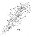
FIG. 1 is a perspective view of a bodily fluid sampling device according to one embodiment of the present invention.FIG. 2 is an enlarged, perspective view of theFIG. 1 device.FIG. 3 is a cross sectional view of theFIG. 1 device forming an incision into skin.FIG. 4 is a cross sectional view of theFIG. 1 device temporarily retracted from the skin.FIG. 5 is a cross sectional view of theFIG. 1 device configured to collect fluid from the incision.- For the purposes of promoting an understanding of the principles of the invention, reference will now be made to the embodiments illustrated in the drawings and specific language will be used to describe the same. It will nevertheless be understood that no limitation of the scope of the invention is thereby intended, such alterations and further modifications in the illustrated device, and such further applications of the principles of the invention as illustrated therein being contemplated as would normally occur to one skilled in the art to which the invention relates.
- The present invention generally concerns an integrated skin lancing device that reduces the number of steps involved in forming, collecting, and testing a bodily fluid sample from an incision. More specifically, the device is operable to automatically cock the lancing mechanism, and the device is further operable to temporarily lift the device from contact with the skin and reposition the device over the incision site in order to collect a fluid sample. By temporarily lifting the device from the skin, no pressure is applied to the skin by the device, which could potentially close the incision and limit the fluid supply for the sample. In one embodiment, the device includes an electric motor that automatically cocks the lancing mechanism and temporarily lifts a fluid collection means from the skin. It is contemplated that, in another embodiment, a purely mechanical system can be used to temporarily lift the fluid collection means.
- An integrated bodily
fluid sampling device 30 according to one embodiment, among others, of the present invention will now be described with reference toFIGS. 1-2 . As depicted inFIG. 1 ,device 30 includes asampling end portion 32 and anactuation end portion 34. Thesampling end portion 32 includes an integrated lancet/sampling device 36, aholder 38 fordevice 36, and adepth control mechanism 40.Device 36 is configured to lance an incision into the skin, collect a bodily fluid sample from the incision, and analyze the fluid sample. Indevice 36, a lancet orblade 42 for forming the incision is housed in acasing 44. For illustration purposes, so that thelancet 42 can be seen inFIG. 1 ,lancet 42 is shown in an extended state. Normally, when thelancet 42 is not lancing the skin, thelancet 42 is retracted inside thecasing 44. During lancing, thecasing 44 is pressed against the skin to form a reference surface on which the penetration depth of thelancet 42 is based. Asdevice 36 is further pressed against the skin, thecasing 44 slides relative to thelancet 42 such that thelancet 42 is exposed, thereby lancing the incision into the skin.Device 36 further includes a test strip ormedia 46 for analyzing the fluid sample. Thetest strip 46 can analyze fluid through such means as optical (e.g., reflectance, absorption, fluorescence, RAMAN, etc.), electrochemical, and/or magnetic analysis, to name a few. In one embodiment, the test strip analyzes fluid optically through a chemical reagent. A capillary channel is formed between thecasing 44 and thelancet 42, which draws fluid onto thetest strip 46 via capillary action. As previously mentioned theholder 32 holdsdevice 36 during lancing. Thedepth control mechanism 40 is used to control and change the penetration depth of thelancet 42 into the skin. For a further discussion of these components in thesampling end portion 32 as well as their function, please refer commonly ownedU.S. Patent Application Serial Number 10/330,724 fluid sampling device 30 according to the present invention can be modified to be used in conjunction with other types of lancing and/or sampling devices. FIG. 2 illustrates an enlarged view of theactuation portion 34 of thesampling device 30. So that theactuation portion 34 can be easily viewed,FIGS. 1 and2 show thedevice 30 without a housing. However, it should be appreciated thatdevice 30 can include a housing in order to protect the components ofdevice 30 from the outside environment. As shown, theactuation portion 34 includes asupport structure 48 that supports amotor 50 as well as afiring mechanism 52. Thefiring mechanism 52 is used to fire the integrated lancet/sampling device 36 in order to lance the skin, and themotor 50 is used to cock thefiring mechanism 52 as well as to temporarily retractdevice 36 after lancing. Thesupport structure 48 in the illustrated embodiment has first 54 and second 56 support arms that are connected together through anactuation guide member 58 such thatsupport structure 48 is shaped in the form of a "C". Oppositeguide member 58, the first 54 and second 56 support arms respectively have first 60 and second 62 motor mounts in which themotor 50 is mounted. The illustratedmotor 50 has a generally cylindrical shape, but it is contemplated thatmotor 50 can have other shapes. As illustrated, motor mounts 60 and 62 each have a hollow cylindrical shape so as to coincide with the cylindrical shape of themotor 50 such thatmotor 50 is able to fit inside mounts 60 and 62. However, it should be appreciated that motor mounts 60 and 62 can be shaped differently so as to coincide with the shape of differently shaped motors.- In the illustrated embodiment, the
motor 50 includes a reversible electric motor, but it should be appreciated thatmotor 50 can include other types of motors, such as a pneumatic motor. Moreover, in another embodiment in which themotor 50 is non-reversible, thedevice 30 can include as transmission configured to reverse the outputted force from themotor 50. In one embodiment, themotor 50 is powered by an internal power source, such as a battery or a fuel cell, but it is contemplated that themotor 50 can be powered in other manners, such as externally through an electrical outlet. As depicted inFIGS. 1 and2 , themotor 50 has a drive shaft with adrive gear 64 that extends through thefirst support arm 54. Areduction gear 66, which is rotatably mounted to thefirst support arm 54, operatively engages thedrive gear 64 of themotor 50. Thefiring mechanism 52 includes aguide rod 68 that extends between the first 54 and second 56 support arms along longitudinal axis L of thedevice 30. As illustrated, theguide rod 68 is rotatably mounted to the first 54 and second 56 support arms via first 70 and second 72 bushings, respectively. At thefirst support arm 54, theguide rod 68 operatively engages thereduction gear 66 such that themotor 50 is able to rotate theguide rod 68. A drive thread orcoil 74, which winds in a helical pattern around theguide rod 68, is attached to theguide rod 68 at both ends throughbushings drive thread 74 are directly attached to theguide rod 68. As noted above, theguide rod 68 is operatively engaged to themotor 50 via thereduction gear 66. Both theguide rod 68 and thedrive thread 74, in the illustrated embodiment, rotate in unison as themotor 50 rotates thereduction gear 66. It is contemplated that in another embodiment only thedrive thread 74 operatively engages thereduction gear 66 such that theguide rod 68 remains stationary as thedrive thread 74 rotates. - Referring to
FIG. 2 , thefiring mechanism 52 further includes adrive member 76 that engages thedrive thread 74 and anactuation member 78 that is coupled toholder 38. A spring (or elastic means) 80 is coupled between thedrive member 76 and theactuation member 78. Among its many functions, thespring 80 is used to fire thelancet 42 fromdevice 36. During cocking, themotor 50 viadrive thread 74 drives thedrive member 76 towards theactuation member 78 such that thespring 80 is compressed therebetween. As will be described in greater detail below, the potential energy stored by thecompressed spring 80 is then used to fire theactuation member 78, which in turn extends thelancet 42 from the integrated lancet/sampling device 36. - As depicted, the
drive member 76 has arod engagement portion 82 that is slidably received along theguide rod 68. InFIG. 2 , therod engagement portion 82 is positioned inside thedrive thread 74 and has one or morethread engaging arms 84 extending therefrom that engage thedrive thread 74. In the illustrated embodiment, therod engagement portion 82 has a pair of L-shapedthread engaging arms 84 positioned on opposite sides of therod engagement portion 82, and thethread engaging arms 84 extend through thedrive thread 74. It should be appreciated that the rod engagement portion can include more or lessthread engaging arms 82 than is shown. Through the engagement between thedrive thread 74 and thethread engaging arms 84, themotor 50 is able to move thedrive member 76 along longitudinal axis L in either a driving direction D or a retraction direction R. For example, rotating thedrive thread 74 in a clockwise fashion moves thedrive member 76 in direction D, and rotating thedrive thread 74 in a counterclockwise fashion moves thedrive member 76 in direction R. It should be appreciated, however, that thedrive thread 74 in other embodiments can be coiled in an opposite fashion such that thedrive thread 74 can be rotated in clockwise direction to move thedrive member 76 in direction R and counterclockwise to move thedrive member 76 in direction D. - The
drive member 76 further includes aspring engagement portion 86 and an actuationmember engagement portion 88. As shown, thespring 80 is attached to thespring engagement portion 86, and thethread engaging arms 84 attach therod engagement portion 82 to thespring engagement portion 86. In the illustrated embodiment, thespring engagement portion 86 is ring shaped so as to fit around thedrive thread 74. One ormore guide arms 90 connect thespring engagement portion 86 to the actuationmember engagement portion 88. As shown, thedrive member 76 in the illustrated embodiment has a pair ofguide arms 90 that are disposed on opposite sides of thedrive member 76. At least one of theguide arms 90 is constructed to include aguide tab 92 that is slidably received between a pair ofguide rails 94 that extend from theguide member 58 of thesupport structure 48. It, however, should be understood thatdevice 30 can include more or less guidearms 90 andguide rails 94 than is shown. The guide rails 94 in conjunction with theguide tab 92 direct thedrive member 76 to move along the longitudinal axis L and prevent thedrive member 76 from rotating in response to the rotation of thedrive thread 74. Referring toFIG. 2 ,portion 88 of thedrive member 74 defines aspring opening 96 through which thespring 80, thedrive thread 74 and theguide rod 68 extend. Around opening 96 thedrive member 76 defines one ormore engagement notches 98 in which theactuation member 78 is slidably received. - With reference to
FIG. 1 , theactuation member 78 includes one or more (and in the illustrated embodiment a pair of) slidearms 100 that are slidably received in theengagement notches 98 defined in thedrive member 78. Each of theslide arms 100 has astop tab 102 located at the end proximal thedrive member 76. As shown, thestop tab 102 has a beveled insertion surface 104 that aids in slidably attaching theactuation member 78 toportion 88 of thedrive member 76. At thesecond support arm 56, theslide arms 100 extend throughslide arm openings 106 that are defined in thesecond support arm 56 such that theslide arms 100 are able to move in a sliding fashion throughopenings 106. The ends of theslide arms 100 that are connected to theholder 38 are connected together via aconnection member 108. In thesupport structure 48, theslide arms 100 are connected to together through a cockingflange 110. In the illustrated embodiment, the cockingflange 110 is ring shaped and defines athread opening 112 through which thedrive thread 74 extends. - As shown in
FIG. 2 , thespring 80 is attached to the cockingflange 110 such that thespring 80 is coupled between thespring engagement portion 86 of thedrive member 76 and the cockingflange 110 of theactuation member 78. During cocking of thedevice 30, themotor 50 rotates thedrive thread 74 so that thedrive member 76 is driven toward the cockingflange 110 of theactuation member 78. As thedrive member 76 is driven towardsflange 110, a pair of cockingarms 114, which extend from thesecond support arm 56 in a parallel arrangement with respect to the longitudinal axis L, support the cockingflange 110 against the force applied by thespring 80. It should be appreciated thatdevice 30 in other embodiments can include one or more cockingarms 114. The cockingarms 114 havesupport tabs 116 that face one another in order to support the cockingflange 110 during cocking. Proximal thedrive member 76, the cockingarms 114 have drive member engagement surfaces 118 with an angled or beveled shape. Similarly, thedrive member 76 has cocking arm engagement surfaces 120 that are likewise beveled or angled to coincide with the shape of the drive member engagement surfaces 118. As thedrive member 76 is driven towards the cockingarms 114 during cocking, the cocking arm engagement surfaces 120 spread the cockingarms 114 apart such that the cockingflange 110 is released. Uponflange 110 being released, thecompressed spring 80 drives the cockingflange 110 away from thedrive member 76, thereby driving the integrated lancet/sampling device 36 to lance the skin. As depicted inFIG. 2 , the cockingarms 114 further have reengagementsurfaces 122 that are angled in order to allow the cockingflange 110 to reengage thesupport tabs 116. - The operation of the integrated bodily
fluid sampling device 30 according to one embodiment will now be described with reference toFIGS. 1 ,2 ,3, 4 and 5. FIGS. 3, 4 and 5 illustrate the relative position of thesampling device 36 in relation to skin S during the sampling technique according to one embodiment of the present invention. In the illustrated embodiment,device 30 has ahousing 124 that is coupled to thesupport structure 48, and as shown, thehousing 124 includes askin contact portion 126, which surrounds thesampling device 36, so as to positiondevice 30 with the skin S. In one form, theskin contact portion 126 is cylindrical in shape, but it is should be appreciated that theskin contact portion 126 can be shaped differently. Moreover, it is contemplated that in other embodiments theskin contact portion 126 can be entirely or partially omitted such that the person using thefluid sampling device 30 manually holdsdevice 30 in position over the skin S. Theskin contact portion 126 in the illustrated embodiment is sized so as to not to apply force to the skin that can close incision I once formed. - Initially, the cocking
flange 110 of thefiring mechanism 52 engages thesupport tabs 116 of the cockingarms 114, as is shown inFIG. 1 . In on order to initiate lancing, theuser positions device 36 either in contact with or proximal to the skin S. In the embodiment illustrated inFIG. 3 , the user presses theskin contact portion 126 against the skin S so as to positiondevice 36. To cock thefiring mechanism 52, as depicted inFIG. 2 , themotor 50 viareduction gear 66 rotates thedrive thread 74 so that thedrive member 76 is driven in driving direction D along longitudinal axis L towards the cockingflange 110 of theactuation member 78. Cocking can be initiated by the user through a switch ondevice 30 that activates themotor 50 and/or automatically through a controller in thedevice 30. It should be appreciated that themotor 50 can be activated in other manners. Since the cockingflange 110 is engaged with the cockingarms 114, thespring 80 in thefiring mechanism 52 becomes compressed as thedrive member 76 is driven in direction D. When thedrive member 76 is further driven in direction D, thestop tabs 102 of theactuation member 78 disengage from the actuationmember engagement portion 88 of thedrive member 76 such that theslide arms 100 slide within theengagement openings 98 of thedrive member 76. Eventually, as thespring 80 becomes further compressed by thedrive member 76, the arm engagement surfaces 120 on thedrive member 76 engage the drive member engagement surfaces 118 on the cockingarms 114 such that the cockingarms 114 are pried apart from one another. Oncearms 114 are sufficiently bent away from one another, thesupport tabs 116 on the cockingarms 114 disengage from the cockingflange 110. - As soon as the cocking
flange 110 is disengaged, thecompressed spring 80 expands so as to drive theactuation member 78 in direction D towards the skin. After thefiring mechanism 52 is fired, themotor 50 in one embodiment stops driving thedrive member 76. In one form, a timer is used to control the operation of themotor 50. Nevertheless, it is contemplated that themotor 50 can be controlled in other manners, such as through a controller and sensors. When theactuation member 78 is fired, theactuation member 78 presses thecasing 44 of the integrated lancet/sampling device 36 against the skin, and thelancet 42 inside thecasing 44 slides relative to thecasing 44 so as to extend from thecasing 44, thereby lancing the incision I in the skin S (FIG. 3 ). Thedepth control mechanism 40 controls the penetration depth of thelancet 42. Once the incision of the proper depth is formed, a retraction mechanism, such as a leaf spring indevice 36, retracts thelancet 42 back inside thecasing 44. In addition, the forward progression of theactuation member 78 in direction D is stopped in one embodiment by thestop tabs 102 contacting the actuationmember engagement portion 88 on thedrive member 76. In another embodiment, the movement of theactuation member 78 is stopped by the cockingflange 110 hitting thesecond support arm 56. - To prevent the pressure applied by the
casing 44 from prematurely closing the incision, thereby limiting the fluid supplied from the incision, the bodilyfluid sampling device 30 according to one embodiment of the present invention temporarily lifts the integrated lancet/sampling device 36 in direction R from the skin, as is shown inFIG. 4 . Afterwards, the bodilyfluid sampling device 30 reapplies thecasing 44 ofdevice 36 against the skin orpositions device 36 proximal the skin such that the integrated lancet/sampling device 36 is able to collect a fluid sample from the incision, as is illustrated inFIG. 5 . As should be appreciated, this sampling technique according to the present invention increases the size of the fluid sample by not restricting the fluid flow from the incision I. In one embodiment, the bodilyfluid sampling device 30 lifts the integrated lancet/sampling device 36 for two (2) seconds before reapplyingdevice 36 against the skin. However, it should be appreciated thatdevice 36 can be temporarily lifted from the skin for different time intervals. To temporarily removedevice 36 from the skin S, themotor 50 inFIG. 2 is reversed such that thedrive thread 74 is rotated in an opposite direction (as compared to when cocking the firing mechanism), thereby moving thedrive member 76 in retraction direction R. For example, thedrive thread 74 can be rotated in a clockwise direction to movedrive member 76 in direction D and can be rotated in a counterclockwise direction so as to move thedrive member 76 in direction R. As should be appreciated, thedrive member 76 in other embodiments can be advanced in direction D and retracted in direction R by rotating thedrive thread 74 in an opposite fashion. While thedrive member 76 is driven in direction R, thestop tabs 102, which engage thedrive member 76, also pull theactuation member 78 in direction R. When theactuation member 78 is moved in direction R,device 36 is likewise moved in direction R, thereby lifting thecasing 44 ofdevice 36 from the skin S (FIG. 4 ). In one embodiment, the integrated lancet/sampling device 36 is lifted a small distance from the skin, and in particular,device 36 is lifted 1mm from the skin. It should be appreciated, however, thatdevice 36 can be retracted at different distances from the skin. - Once
device 36 has been lifted from the skin for a short period of time, themotor 50 is then again reversed so as to drive thedrive member 76 in direction D. The force applied by thedrive member 76 against thespring 80 is transferred to theactuation member 78 so thatdevice 36 is moved in direction D towards the skin (FIG. 5 ). When the integrated lancet/sampling device 36 contacts the skin S or is positioned at the desired distance from the skin S, themotor 50 can be deenergized. The bodily fluid F that has formed as a droplet from the incision I in the skin S is drawn via capillary action into the capillary cavity formed in thecasing 44 and deposited onto thetest strip 46 indevice 36 so that the fluid sample can be analyzed. - To reset the bodily
fluid sampling device 30 for future sample collection, themotor 50 drives thedrive member 76 in the retraction direction R such that theactuation mechanism 78 is likewise pulled in the retraction direction R. As theactuation mechanism 78 is pulled in direction R, the cockingflange 110 engages the reengagement surfaces 122 on the cockingarms 114, and thearms 114 are pried apart so that the cockingflange 110 reengages thesupport tabs 116 on the cockingarms 114. Once the bodilyfluid sampling device 30 is reset, thefiring mechanism 52 can be again cocked and fired in the manner as described above. - It is contemplated that, in another embodiment, a purely mechanical device can be used to accomplish the sampling technique as described above in which the integrated lancet/sampling device is temporarily removed and reapplied to the skin. In one form, a hydraulic and/or pneumatic cylinder is used to dampen or slow the mechanical movement in which the integrated lancet/sampling device is temporarily removed and reapplied.
- While the invention has been illustrated and described in detail in the drawings and foregoing description, the same is to be considered as illustrative and not restrictive in character, it being understood that only the preferred embodiment has been shown and described and that all changes and modifications that come within the spirit of the invention are desired to be protected.
Claims (4)
- A body fluid sampling device, comprising:an integrated lancing-sampling device including a test strip for analyzing a body fluid and a casing (44) and a lancet for lancing an incision in skin slidably received in the casing, wherein the casing defines a sampling cavity for drawing body fluid from the incision onto the test strip via capillary action;characterized in that the device further discloses means (78) for pressing the casing against the skin and sliding the lancet inside the casing relative to the casing so as to extend from the casing thereby lancing the incision in the skin, and means (50) for retracting and reapplying against the skin to promote flow of body fluid from the incision.
- The device of claim 1, wherein the means for retracting and reapplying the integrated lancing-sampling device includes a motor operable to retract and reapply the integrated lancing-sampling device against the skin.
- The device of claim 1, further comprising:a firing mechanism coupled to the integrated-sampling device for firing the integrated lancing-sampling device; andmeans for automatically cocking the firing mechanism.
- The device of claim 1, further comprising a depth control mechanism coupled to the integrated lancing-sampling device to adjust the penetration depth of the lancet.
Applications Claiming Priority (3)
| Application Number | Priority Date | Filing Date | Title |
|---|---|---|---|
| US43695202P | 2002-12-30 | 2002-12-30 | |
| US436952P | 2002-12-30 | ||
| PCT/US2003/039906WO2004060143A2 (en) | 2002-12-30 | 2003-12-16 | Suspension for a blood acquisition system |
Publications (2)
| Publication Number | Publication Date |
|---|---|
| EP1581115A2 EP1581115A2 (en) | 2005-10-05 |
| EP1581115B1true EP1581115B1 (en) | 2009-10-14 |
Family
ID=32713110
Family Applications (1)
| Application Number | Title | Priority Date | Filing Date |
|---|---|---|---|
| EP03814826AExpired - LifetimeEP1581115B1 (en) | 2002-12-30 | 2003-12-16 | Blood acquisition suspension system |
Country Status (9)
| Country | Link |
|---|---|
| US (3) | US7351212B2 (en) |
| EP (1) | EP1581115B1 (en) |
| JP (2) | JP4636884B2 (en) |
| AT (1) | ATE445360T1 (en) |
| AU (1) | AU2003300941A1 (en) |
| CA (1) | CA2508894A1 (en) |
| DE (1) | DE60329712D1 (en) |
| ES (1) | ES2334128T3 (en) |
| WO (1) | WO2004060143A2 (en) |
Families Citing this family (122)
| Publication number | Priority date | Publication date | Assignee | Title |
|---|---|---|---|---|
| US6036924A (en) | 1997-12-04 | 2000-03-14 | Hewlett-Packard Company | Cassette of lancet cartridges for sampling blood |
| US6391005B1 (en) | 1998-03-30 | 2002-05-21 | Agilent Technologies, Inc. | Apparatus and method for penetration with shaft having a sensor for sensing penetration depth |
| US20050103624A1 (en) | 1999-10-04 | 2005-05-19 | Bhullar Raghbir S. | Biosensor and method of making |
| DE10057832C1 (en) | 2000-11-21 | 2002-02-21 | Hartmann Paul Ag | Blood analysis device has syringe mounted in casing, annular mounting carrying needles mounted behind test strip and being swiveled so that needle can be pushed through strip and aperture in casing to take blood sample |
| US8641644B2 (en) | 2000-11-21 | 2014-02-04 | Sanofi-Aventis Deutschland Gmbh | Blood testing apparatus having a rotatable cartridge with multiple lancing elements and testing means |
| US7310543B2 (en)* | 2001-03-26 | 2007-12-18 | Kumetrix, Inc. | Silicon microprobe with integrated biosensor |
| US9795747B2 (en) | 2010-06-02 | 2017-10-24 | Sanofi-Aventis Deutschland Gmbh | Methods and apparatus for lancet actuation |
| US9226699B2 (en) | 2002-04-19 | 2016-01-05 | Sanofi-Aventis Deutschland Gmbh | Body fluid sampling module with a continuous compression tissue interface surface |
| WO2002101359A2 (en) | 2001-06-12 | 2002-12-19 | Pelikan Technologies, Inc. | Integrated blood sampling analysis system with multi-use sampling module |
| JP4272051B2 (en) | 2001-06-12 | 2009-06-03 | ペリカン テクノロジーズ インコーポレイテッド | Blood sampling apparatus and method |
| US8337419B2 (en) | 2002-04-19 | 2012-12-25 | Sanofi-Aventis Deutschland Gmbh | Tissue penetration device |
| US7041068B2 (en) | 2001-06-12 | 2006-05-09 | Pelikan Technologies, Inc. | Sampling module device and method |
| US9427532B2 (en) | 2001-06-12 | 2016-08-30 | Sanofi-Aventis Deutschland Gmbh | Tissue penetration device |
| US7749174B2 (en) | 2001-06-12 | 2010-07-06 | Pelikan Technologies, Inc. | Method and apparatus for lancet launching device intergrated onto a blood-sampling cartridge |
| US7344507B2 (en) | 2002-04-19 | 2008-03-18 | Pelikan Technologies, Inc. | Method and apparatus for lancet actuation |
| EP1395185B1 (en) | 2001-06-12 | 2010-10-27 | Pelikan Technologies Inc. | Electric lancet actuator |
| US7981056B2 (en) | 2002-04-19 | 2011-07-19 | Pelikan Technologies, Inc. | Methods and apparatus for lancet actuation |
| JP4209767B2 (en) | 2001-06-12 | 2009-01-14 | ペリカン テクノロジーズ インコーポレイテッド | Self-optimized cutting instrument with adaptive means for temporary changes in skin properties |
| AU2002344825A1 (en) | 2001-06-12 | 2002-12-23 | Pelikan Technologies, Inc. | Method and apparatus for improving success rate of blood yield from a fingerstick |
| DE10134650B4 (en)* | 2001-07-20 | 2009-12-03 | Roche Diagnostics Gmbh | System for taking small amounts of body fluid |
| US7344894B2 (en) | 2001-10-16 | 2008-03-18 | Agilent Technologies, Inc. | Thermal regulation of fluidic samples within a diagnostic cartridge |
| US8702624B2 (en) | 2006-09-29 | 2014-04-22 | Sanofi-Aventis Deutschland Gmbh | Analyte measurement device with a single shot actuator |
| US7371247B2 (en) | 2002-04-19 | 2008-05-13 | Pelikan Technologies, Inc | Method and apparatus for penetrating tissue |
| US7141058B2 (en) | 2002-04-19 | 2006-11-28 | Pelikan Technologies, Inc. | Method and apparatus for a body fluid sampling device using illumination |
| US7547287B2 (en) | 2002-04-19 | 2009-06-16 | Pelikan Technologies, Inc. | Method and apparatus for penetrating tissue |
| US7648468B2 (en) | 2002-04-19 | 2010-01-19 | Pelikon Technologies, Inc. | Method and apparatus for penetrating tissue |
| US7491178B2 (en)* | 2002-04-19 | 2009-02-17 | Pelikan Technologies, Inc. | Method and apparatus for penetrating tissue |
| WO2003088824A2 (en) | 2002-04-19 | 2003-10-30 | Pelikan Technologies, Inc. | Device and method for variable speed lancet |
| US8372016B2 (en) | 2002-04-19 | 2013-02-12 | Sanofi-Aventis Deutschland Gmbh | Method and apparatus for body fluid sampling and analyte sensing |
| US7892183B2 (en) | 2002-04-19 | 2011-02-22 | Pelikan Technologies, Inc. | Method and apparatus for body fluid sampling and analyte sensing |
| US8267870B2 (en) | 2002-04-19 | 2012-09-18 | Sanofi-Aventis Deutschland Gmbh | Method and apparatus for body fluid sampling with hybrid actuation |
| US7582099B2 (en) | 2002-04-19 | 2009-09-01 | Pelikan Technologies, Inc | Method and apparatus for penetrating tissue |
| US9314194B2 (en) | 2002-04-19 | 2016-04-19 | Sanofi-Aventis Deutschland Gmbh | Tissue penetration device |
| US7244265B2 (en) | 2002-04-19 | 2007-07-17 | Pelikan Technologies, Inc. | Method and apparatus for penetrating tissue |
| US7485128B2 (en) | 2002-04-19 | 2009-02-03 | Pelikan Technologies, Inc. | Method and apparatus for penetrating tissue |
| US8579831B2 (en) | 2002-04-19 | 2013-11-12 | Sanofi-Aventis Deutschland Gmbh | Method and apparatus for penetrating tissue |
| US9795334B2 (en) | 2002-04-19 | 2017-10-24 | Sanofi-Aventis Deutschland Gmbh | Method and apparatus for penetrating tissue |
| US8784335B2 (en) | 2002-04-19 | 2014-07-22 | Sanofi-Aventis Deutschland Gmbh | Body fluid sampling device with a capacitive sensor |
| US7524293B2 (en) | 2002-04-19 | 2009-04-28 | Pelikan Technologies, Inc. | Method and apparatus for penetrating tissue |
| US7481776B2 (en) | 2002-04-19 | 2009-01-27 | Pelikan Technologies, Inc. | Method and apparatus for penetrating tissue |
| US7563232B2 (en) | 2002-04-19 | 2009-07-21 | Pelikan Technologies, Inc. | Method and apparatus for penetrating tissue |
| US7976476B2 (en) | 2002-04-19 | 2011-07-12 | Pelikan Technologies, Inc. | Device and method for variable speed lancet |
| US7297122B2 (en) | 2002-04-19 | 2007-11-20 | Pelikan Technologies, Inc. | Method and apparatus for penetrating tissue |
| US7374544B2 (en) | 2002-04-19 | 2008-05-20 | Pelikan Technologies, Inc. | Method and apparatus for penetrating tissue |
| US7229458B2 (en) | 2002-04-19 | 2007-06-12 | Pelikan Technologies, Inc. | Method and apparatus for penetrating tissue |
| US8360992B2 (en) | 2002-04-19 | 2013-01-29 | Sanofi-Aventis Deutschland Gmbh | Method and apparatus for penetrating tissue |
| US7232451B2 (en) | 2002-04-19 | 2007-06-19 | Pelikan Technologies, Inc. | Method and apparatus for penetrating tissue |
| US8221334B2 (en) | 2002-04-19 | 2012-07-17 | Sanofi-Aventis Deutschland Gmbh | Method and apparatus for penetrating tissue |
| US7331931B2 (en) | 2002-04-19 | 2008-02-19 | Pelikan Technologies, Inc. | Method and apparatus for penetrating tissue |
| US7717863B2 (en) | 2002-04-19 | 2010-05-18 | Pelikan Technologies, Inc. | Method and apparatus for penetrating tissue |
| US7901362B2 (en) | 2002-04-19 | 2011-03-08 | Pelikan Technologies, Inc. | Method and apparatus for penetrating tissue |
| US7674232B2 (en) | 2002-04-19 | 2010-03-09 | Pelikan Technologies, Inc. | Method and apparatus for penetrating tissue |
| US7291117B2 (en) | 2002-04-19 | 2007-11-06 | Pelikan Technologies, Inc. | Method and apparatus for penetrating tissue |
| US7909778B2 (en) | 2002-04-19 | 2011-03-22 | Pelikan Technologies, Inc. | Method and apparatus for penetrating tissue |
| US9248267B2 (en) | 2002-04-19 | 2016-02-02 | Sanofi-Aventis Deustchland Gmbh | Tissue penetration device |
| US7410468B2 (en) | 2002-04-19 | 2008-08-12 | Pelikan Technologies, Inc. | Method and apparatus for penetrating tissue |
| US7708701B2 (en) | 2002-04-19 | 2010-05-04 | Pelikan Technologies, Inc. | Method and apparatus for a multi-use body fluid sampling device |
| US7815579B2 (en) | 2005-03-02 | 2010-10-19 | Roche Diagnostics Operations, Inc. | Dynamic integrated lancing test strip with sterility cover |
| US8052926B2 (en)* | 2002-12-27 | 2011-11-08 | Roche Diagnostics Operations, Inc. | Method for manufacturing a sterilized lancet integrated biosensor |
| DE60332043D1 (en)* | 2002-12-30 | 2010-05-20 | Roche Diagnostics Gmbh | CAPILLARY TUBE TOP DESIGN TO SUPPORT BLOOD FLOW |
| US7214200B2 (en)* | 2002-12-30 | 2007-05-08 | Roche Diagnostics Operations, Inc. | Integrated analytical test element |
| US7211052B2 (en)* | 2002-12-30 | 2007-05-01 | Roche Diagnostics Operations, Inc. | Flexible test strip lancet device |
| US8574895B2 (en) | 2002-12-30 | 2013-11-05 | Sanofi-Aventis Deutschland Gmbh | Method and apparatus using optical techniques to measure analyte levels |
| DE602004028463D1 (en) | 2003-05-30 | 2010-09-16 | Pelikan Technologies Inc | METHOD AND DEVICE FOR INJECTING LIQUID |
| US7850621B2 (en) | 2003-06-06 | 2010-12-14 | Pelikan Technologies, Inc. | Method and apparatus for body fluid sampling and analyte sensing |
| WO2006001797A1 (en) | 2004-06-14 | 2006-01-05 | Pelikan Technologies, Inc. | Low pain penetrating |
| EP1635700B1 (en) | 2003-06-13 | 2016-03-09 | Sanofi-Aventis Deutschland GmbH | Apparatus for a point of care device |
| JP4447009B2 (en) | 2003-06-20 | 2010-04-07 | エフ ホフマン−ラ ロッシュ アクチェン ゲゼルシャフト | Test strip with slot vent opening |
| US8071030B2 (en) | 2003-06-20 | 2011-12-06 | Roche Diagnostics Operations, Inc. | Test strip with flared sample receiving chamber |
| US8679853B2 (en) | 2003-06-20 | 2014-03-25 | Roche Diagnostics Operations, Inc. | Biosensor with laser-sealed capillary space and method of making |
| US8148164B2 (en) | 2003-06-20 | 2012-04-03 | Roche Diagnostics Operations, Inc. | System and method for determining the concentration of an analyte in a sample fluid |
| US8282576B2 (en) | 2003-09-29 | 2012-10-09 | Sanofi-Aventis Deutschland Gmbh | Method and apparatus for an improved sample capture device |
| EP1680014A4 (en) | 2003-10-14 | 2009-01-21 | Pelikan Technologies Inc | METHOD AND DEVICE FOR A VARIABLE USER INTERFACE |
| US7822454B1 (en) | 2005-01-03 | 2010-10-26 | Pelikan Technologies, Inc. | Fluid sampling device with improved analyte detecting member configuration |
| US8668656B2 (en) | 2003-12-31 | 2014-03-11 | Sanofi-Aventis Deutschland Gmbh | Method and apparatus for improving fluidic flow and sample capture |
| WO2006011062A2 (en) | 2004-05-20 | 2006-02-02 | Albatros Technologies Gmbh & Co. Kg | Printable hydrogel for biosensors |
| WO2005120365A1 (en) | 2004-06-03 | 2005-12-22 | Pelikan Technologies, Inc. | Method and apparatus for a fluid sampling device |
| US9775553B2 (en) | 2004-06-03 | 2017-10-03 | Sanofi-Aventis Deutschland Gmbh | Method and apparatus for a fluid sampling device |
| DE102004037270B4 (en)* | 2004-07-31 | 2008-01-31 | Roche Diagnostics Gmbh | Blood collection system for taking blood for diagnostic purposes |
| US20060030788A1 (en)* | 2004-08-04 | 2006-02-09 | Daniel Wong | Apparatus and method for extracting bodily fluid utilizing a flat lancet |
| US7645241B2 (en)* | 2004-09-09 | 2010-01-12 | Roche Diagnostics Operations, Inc. | Device for sampling bodily fluids |
| US7604604B2 (en)* | 2004-09-09 | 2009-10-20 | Roche Diagnostics Operations, Inc. | Device for sampling bodily fluids |
| US7488298B2 (en)* | 2004-10-08 | 2009-02-10 | Roche Diagnostics Operations, Inc. | Integrated lancing test strip with capillary transfer sheet |
| US8652831B2 (en) | 2004-12-30 | 2014-02-18 | Sanofi-Aventis Deutschland Gmbh | Method and apparatus for analyte measurement test time |
| US7651851B2 (en)* | 2005-01-27 | 2010-01-26 | Prescient Medical, Inc. | Handheld Raman body fluid analyzer |
| US7524671B2 (en)* | 2005-01-27 | 2009-04-28 | Prescient Medical, Inc. | Handheld raman blood analyzer |
| US7688440B2 (en)* | 2005-01-27 | 2010-03-30 | Prescient Medical, Inc. | Raman spectroscopic test strip systems |
| DE102005004498B4 (en)* | 2005-02-01 | 2009-07-09 | Roche Diagnostics Gmbh | Drive for medical devices and use for such a drive |
| DE102005005017A1 (en)* | 2005-02-03 | 2006-08-17 | Roche Diagnostics Gmbh | Electromechanical lancing device for obtaining liquid samples |
| US7935063B2 (en)* | 2005-03-02 | 2011-05-03 | Roche Diagnostics Operations, Inc. | System and method for breaking a sterility seal to engage a lancet |
| US7955271B2 (en) | 2006-10-13 | 2011-06-07 | Roche Diagnostics Operations, Inc. | Tape transport lance sampler |
| US7695442B2 (en) | 2005-04-12 | 2010-04-13 | Roche Diagnostics Operations, Inc. | Integrated lancing test strip with retractable lancet |
| USD560798S1 (en)* | 2005-03-29 | 2008-01-29 | Enomoto Co., Ltd. | Blood collecting device |
| EP1743577A1 (en)* | 2005-06-23 | 2007-01-17 | Roche Diagnostics GmbH | Hand-held apparatus for the analysis of bodily fluids |
| US8048098B2 (en)* | 2005-07-14 | 2011-11-01 | Bayer Healthcare Llc | Lancing device for one skin puncture |
| EP1759635A1 (en)* | 2005-09-03 | 2007-03-07 | Boehringer Mannheim Gmbh | Pricking method and hand held device therefore |
| DE102005055398A1 (en)* | 2005-11-17 | 2007-05-31 | Wittenstein Ag | Device for recording diagnostic values in the body |
| JPWO2007063948A1 (en)* | 2005-12-01 | 2009-05-07 | アークレイ株式会社 | Sensor-lancet integrated device and body fluid collecting method using the same |
| EP1792568A1 (en)* | 2005-12-05 | 2007-06-06 | F. Hoffmann-La Roche AG | Re-usable puncturing aid and method for performing a puncture movement therewith |
| WO2007092173A2 (en)* | 2006-02-06 | 2007-08-16 | Prescient Medical, Inc. | Raman spectroscopic lateral flow test strip assays |
| CN101437560A (en)* | 2006-05-04 | 2009-05-20 | 诺沃-诺迪斯克有限公司 | Injection device with electric motor for filling injection chamber |
| ES2421781T3 (en)* | 2006-09-04 | 2013-09-05 | Hoffmann La Roche | Puncture system to extract a body fluid |
| US8852124B2 (en)* | 2006-10-13 | 2014-10-07 | Roche Diagnostics Operations, Inc. | Tape transport lance sampler |
| JP4986290B2 (en)* | 2007-02-26 | 2012-07-25 | 独立行政法人産業技術総合研究所 | Sensor device |
| ES2354912T3 (en) | 2007-05-16 | 2011-03-21 | Roche Diagnostics Gmbh | PUNCTURE SYSTEM |
| EP2265324B1 (en) | 2008-04-11 | 2015-01-28 | Sanofi-Aventis Deutschland GmbH | Integrated analyte measurement system |
| BRPI0913380A2 (en) | 2008-06-04 | 2015-11-24 | Neovista Inc | portable radiation release system for advancing a radiation source wire |
| US9375169B2 (en) | 2009-01-30 | 2016-06-28 | Sanofi-Aventis Deutschland Gmbh | Cam drive for managing disposable penetrating member actions with a single motor and motor and control system |
| US20100198107A1 (en)* | 2009-01-30 | 2010-08-05 | Roche Diagnostics Operations, Inc. | Integrated blood glucose meter and lancing device |
| USD618338S1 (en)* | 2009-05-15 | 2010-06-22 | Panasonic Corporation | Syringe drive device |
| US8061004B2 (en) | 2009-08-20 | 2011-11-22 | Roche Diagnostics Operations, Inc. | Method of manufacturing a test strip |
| USD619713S1 (en)* | 2009-10-19 | 2010-07-13 | Stanley Kim | Lancet head |
| WO2011102643A2 (en)* | 2010-02-16 | 2011-08-25 | Choi In Sang | Blood glucose measuring system, strip receiving apparatus, strip storage apparatus and automatic blood collecting apparatus |
| US8965476B2 (en) | 2010-04-16 | 2015-02-24 | Sanofi-Aventis Deutschland Gmbh | Tissue penetration device |
| US20120330188A1 (en)* | 2011-06-21 | 2012-12-27 | Gadlight, Inc. | Cocking and Advancing Mechanism for Analyte Testing Device |
| US8333716B1 (en) | 2011-06-21 | 2012-12-18 | Yofimeter, Llc | Methods for using an analyte testing device |
| US20130085349A1 (en) | 2011-06-21 | 2013-04-04 | Yofimeter, Llc | Analyte testing devices |
| US9933409B2 (en) | 2011-11-15 | 2018-04-03 | Roche Diabetes Care, Inc. | Strip connector with reliable insertion and ejection |
| CN106236112A (en)* | 2016-08-23 | 2016-12-21 | 天津华鸿科技股份有限公司 | Blood sampling collection from heel device |
| CN106290811B (en)* | 2016-11-17 | 2019-03-29 | 百奥森(江苏)食品安全科技有限公司 | A kind of automatic locking and the illicit drugs inspection card for facilitating sampling |
| CN108937961B (en)* | 2018-07-31 | 2019-11-05 | 苏州施莱医疗器械有限公司 | A kind of hemostix spring tail portion elastic dilatation latching structure |
| CN109520781B (en)* | 2018-11-23 | 2021-05-14 | 周瑛瑛 | Blood sampler for pediatric examination |
Family Cites Families (67)
| Publication number | Priority date | Publication date | Assignee | Title |
|---|---|---|---|---|
| US5803A (en)* | 1848-09-26 | Improved machine for turning the heads of wood-screws | ||
| US35803A (en)* | 1862-07-01 | Improvement in sash-fasteners | ||
| DE2118455B1 (en)* | 1971-04-16 | 1972-09-21 | Boehringer Mannheim Gmbh | Test strips |
| US3854471A (en)* | 1972-09-15 | 1974-12-17 | J Wild | Ultrasonic method for systematic search and detection of tissue abnormalities |
| DE2436598C2 (en)* | 1974-07-30 | 1983-04-07 | Boehringer Mannheim Gmbh, 6800 Mannheim | Stable test strip for the detection of ingredients in liquids |
| FR2437668A1 (en)* | 1978-09-29 | 1980-04-25 | Thomson Csf | PROTECTED OPTICAL DISC |
| GB2072750B (en)* | 1980-03-28 | 1983-10-26 | Miles M A P | Rotary positive-displacement fluidmachines |
| US4360016A (en)* | 1980-07-01 | 1982-11-23 | Transidyne General Corp. | Blood collecting device |
| DE3211167A1 (en)* | 1982-03-26 | 1983-09-29 | Merck Patent Gmbh, 6100 Darmstadt | TEST SYSTEM AND METHOD FOR DETERMINING SUBSTANCES IN LIQUIDS |
| US4628445A (en)* | 1983-10-18 | 1986-12-09 | International Business Machines Corporation | Apparatus and method for synchronization of peripheral devices via bus cycle alteration in a microprocessor implemented data processing system |
| US4490485A (en)* | 1984-03-23 | 1984-12-25 | Texaco Inc. | Manufacture of flexible polyurethane foam containing a condensation product of polyethylene terephthalate |
| US4787398A (en)* | 1985-04-08 | 1988-11-29 | Garid, Inc. | Glucose medical monitoring system |
| US4627445A (en)* | 1985-04-08 | 1986-12-09 | Garid, Inc. | Glucose medical monitoring system |
| US4653513A (en)* | 1985-08-09 | 1987-03-31 | Dombrowski Mitchell P | Blood sampler |
| US4824879A (en)* | 1986-06-20 | 1989-04-25 | Minnesota Mining And Manufacturing Company | Low shrinkage tape joint composition containing attapulgite |
| GB8710470D0 (en)* | 1987-05-01 | 1987-06-03 | Mumford Ltd Owen | Blood sampling devices |
| US4924879A (en)* | 1988-10-07 | 1990-05-15 | Brien Walter J O | Blood lancet device |
| US5231993A (en) | 1991-11-20 | 1993-08-03 | Habley Medical Technology Corporation | Blood sampler and component tester with guide member |
| DE4212315A1 (en) | 1992-04-13 | 1993-10-14 | Boehringer Mannheim Gmbh | Blood lancet device for drawing blood for diagnostic purposes |
| JPH0784781A (en) | 1993-09-13 | 1995-03-31 | Nec Corp | Information processor |
| JP3685530B2 (en)* | 1995-09-20 | 2005-08-17 | 大日本印刷株式会社 | Blood analyzer |
| US5962215A (en)* | 1996-04-05 | 1999-10-05 | Mercury Diagnostics, Inc. | Methods for testing the concentration of an analyte in a body fluid |
| US5776719A (en)* | 1997-07-07 | 1998-07-07 | Mercury Diagnostics, Inc. | Diagnostic compositions and devices utilizing same |
| US5879311A (en)* | 1996-05-17 | 1999-03-09 | Mercury Diagnostics, Inc. | Body fluid sampling device and methods of use |
| US5951492A (en)* | 1996-05-17 | 1999-09-14 | Mercury Diagnostics, Inc. | Methods and apparatus for sampling and analyzing body fluid |
| EP1862116A3 (en)* | 1996-05-17 | 2009-02-25 | Roche Diagnostics Operations, Inc. | Disposable element for use in a body fluid sampling device |
| US6332871B1 (en)* | 1996-05-17 | 2001-12-25 | Amira Medical | Blood and interstitial fluid sampling device |
| DE19758948B3 (en)* | 1996-05-17 | 2013-11-14 | Roche Diagnostics Operations, Inc. | Multi-chamber tube for use in a body fluid sampling device for collecting a body fluid sample |
| EP1579814A3 (en)* | 1996-05-17 | 2006-06-14 | Roche Diagnostics Operations, Inc. | Methods and apparatus for sampling and analyzing body fluid |
| US5951493A (en)* | 1997-05-16 | 1999-09-14 | Mercury Diagnostics, Inc. | Methods and apparatus for expressing body fluid from an incision |
| US5857983A (en)* | 1996-05-17 | 1999-01-12 | Mercury Diagnostics, Inc. | Methods and apparatus for sampling body fluid |
| US5824491A (en)* | 1996-05-17 | 1998-10-20 | Mercury Diagnostics, Inc. | Dry reagent test strip comprising benzidine dye precursor and antipyrine compound |
| JPH1014905A (en) | 1996-06-25 | 1998-01-20 | Becton Dickinson & Co | Sample assembly |
| JP3604816B2 (en)* | 1996-07-01 | 2004-12-22 | 大日本印刷株式会社 | Body fluid analyzer |
| US5873887A (en)* | 1996-10-25 | 1999-02-23 | Bayer Corporation | Blood sampling device |
| US6027459A (en)* | 1996-12-06 | 2000-02-22 | Abbott Laboratories | Method and apparatus for obtaining blood for diagnostic tests |
| AU6157898A (en)* | 1997-02-06 | 1998-08-26 | E. Heller & Company | Small volume (in vitro) analyte sensor |
| FI111217B (en)* | 1997-06-19 | 2003-06-30 | Nokia Corp | Device for sampling |
| US6056765A (en)* | 1997-06-24 | 2000-05-02 | Bajaj; Ratan | Lancet device |
| US6436116B1 (en)* | 1997-10-06 | 2002-08-20 | Smith & Nephew, Inc. | Methods and apparatus for removing veins |
| US5964718A (en)* | 1997-11-21 | 1999-10-12 | Mercury Diagnostics, Inc. | Body fluid sampling device |
| US6071294A (en)* | 1997-12-04 | 2000-06-06 | Agilent Technologies, Inc. | Lancet cartridge for sampling blood |
| US5971941A (en)* | 1997-12-04 | 1999-10-26 | Hewlett-Packard Company | Integrated system and method for sampling blood and analysis |
| US5997817A (en)* | 1997-12-05 | 1999-12-07 | Roche Diagnostics Corporation | Electrochemical biosensor test strip |
| US6086545A (en)* | 1998-04-28 | 2000-07-11 | Amira Medical | Methods and apparatus for suctioning and pumping body fluid from an incision |
| CN1191786C (en)* | 1999-01-04 | 2005-03-09 | 泰尔茂株式会社 | Assembly with piercing part and body fluid collection and detection device |
| US6210420B1 (en)* | 1999-01-19 | 2001-04-03 | Agilent Technologies, Inc. | Apparatus and method for efficient blood sampling with lancet |
| US6306152B1 (en)* | 1999-03-08 | 2001-10-23 | Agilent Technologies, Inc. | Lancet device with skin movement control and ballistic preload |
| US6283982B1 (en)* | 1999-10-19 | 2001-09-04 | Facet Technologies, Inc. | Lancing device and method of sample collection |
| US6612111B1 (en)* | 2000-03-27 | 2003-09-02 | Lifescan, Inc. | Method and device for sampling and analyzing interstitial fluid and whole blood samples |
| AU2001279282A1 (en)* | 2000-07-07 | 2002-01-21 | Fluidsense Corporation | Pump cassette with controlled pump force |
| US6561989B2 (en)* | 2000-07-10 | 2003-05-13 | Bayer Healthcare, Llc | Thin lance and test sensor having same |
| AU2002221075A1 (en) | 2000-12-06 | 2002-06-18 | Kabushiki Kaisya Advance | Facilitated body fluid inspection unit |
| CN101366633B (en)* | 2001-01-19 | 2011-03-30 | 松下电器产业株式会社 | Lancet-integrated sensor, measurement device, and biosensor case |
| WO2002056751A2 (en)* | 2001-01-22 | 2002-07-25 | Roche Diagnostics Gmbh | Lancet device having capillary action |
| US6591124B2 (en)* | 2001-05-11 | 2003-07-08 | The Procter & Gamble Company | Portable interstitial fluid monitoring system |
| US20020177763A1 (en)* | 2001-05-22 | 2002-11-28 | Burns David W. | Integrated lancets and methods |
| US6988996B2 (en)* | 2001-06-08 | 2006-01-24 | Roche Diagnostics Operatons, Inc. | Test media cassette for bodily fluid testing device |
| JP4209767B2 (en)* | 2001-06-12 | 2009-01-14 | ペリカン テクノロジーズ インコーポレイテッド | Self-optimized cutting instrument with adaptive means for temporary changes in skin properties |
| EP1395185B1 (en)* | 2001-06-12 | 2010-10-27 | Pelikan Technologies Inc. | Electric lancet actuator |
| US7041068B2 (en)* | 2001-06-12 | 2006-05-09 | Pelikan Technologies, Inc. | Sampling module device and method |
| US7344507B2 (en)* | 2002-04-19 | 2008-03-18 | Pelikan Technologies, Inc. | Method and apparatus for lancet actuation |
| US7264627B2 (en)* | 2001-08-29 | 2007-09-04 | Roche Diagnostics Operations, Inc. | Wicking methods and structures for use in sampling bodily fluids |
| US8267870B2 (en)* | 2002-04-19 | 2012-09-18 | Sanofi-Aventis Deutschland Gmbh | Method and apparatus for body fluid sampling with hybrid actuation |
| CN1703163A (en)* | 2002-10-09 | 2005-11-30 | Csp技术公司 | Lancet system including test strips and cassettes |
| US20050049522A1 (en)* | 2002-10-30 | 2005-03-03 | Allen John J | Method of lancing skin for the extraction of blood |
| US20040127818A1 (en) | 2002-12-27 | 2004-07-01 | Roe Steven N. | Precision depth control lancing tip |
- 2003
- 2003-12-16EPEP03814826Apatent/EP1581115B1/ennot_activeExpired - Lifetime
- 2003-12-16ATAT03814826Tpatent/ATE445360T1/ennot_activeIP Right Cessation
- 2003-12-16AUAU2003300941Apatent/AU2003300941A1/ennot_activeAbandoned
- 2003-12-16USUS10/737,660patent/US7351212B2/ennot_activeExpired - Lifetime
- 2003-12-16CACA002508894Apatent/CA2508894A1/ennot_activeAbandoned
- 2003-12-16JPJP2004565515Apatent/JP4636884B2/ennot_activeExpired - Fee Related
- 2003-12-16WOPCT/US2003/039906patent/WO2004060143A2/enactiveApplication Filing
- 2003-12-16ESES03814826Tpatent/ES2334128T3/ennot_activeExpired - Lifetime
- 2003-12-16DEDE60329712Tpatent/DE60329712D1/ennot_activeExpired - Lifetime
- 2006
- 2006-07-17USUS11/457,872patent/US7927291B2/ennot_activeExpired - Fee Related
- 2008
- 2008-09-08JPJP2008229551Apatent/JP2008289934A/enactivePending
- 2011
- 2011-03-16USUS13/049,622patent/US8684951B2/ennot_activeExpired - Fee Related
Also Published As
| Publication number | Publication date |
|---|---|
| US8684951B2 (en) | 2014-04-01 |
| JP4636884B2 (en) | 2011-02-23 |
| CA2508894A1 (en) | 2004-07-22 |
| ATE445360T1 (en) | 2009-10-15 |
| WO2004060143A2 (en) | 2004-07-22 |
| ES2334128T3 (en) | 2010-03-05 |
| EP1581115A2 (en) | 2005-10-05 |
| US7927291B2 (en) | 2011-04-19 |
| AU2003300941A1 (en) | 2004-07-29 |
| WO2004060143A3 (en) | 2004-09-10 |
| AU2003300941A8 (en) | 2004-07-29 |
| US20040127819A1 (en) | 2004-07-01 |
| US20110166477A1 (en) | 2011-07-07 |
| US7351212B2 (en) | 2008-04-01 |
| DE60329712D1 (en) | 2009-11-26 |
| JP2008289934A (en) | 2008-12-04 |
| US20060247554A1 (en) | 2006-11-02 |
| JP2006512155A (en) | 2006-04-13 |
Similar Documents
| Publication | Publication Date | Title |
|---|---|---|
| EP1581115B1 (en) | Blood acquisition suspension system | |
| JP2006512155A5 (en) | ||
| US9538941B2 (en) | Devices and methods for expression of bodily fluids from an incision | |
| AU2002247008B2 (en) | Lancet device having capillary action | |
| EP1581114B1 (en) | Flexible test strip lancet device | |
| US9554741B2 (en) | Precision depth control lancing tip | |
| JP3934107B2 (en) | Test strip for collecting body fluid and method for collecting body fluid | |
| CA2458208A1 (en) | Wicking methods and structures for use in sampling bodily fluids | |
| EP1399066B1 (en) | Devices for the expression of bodily fluids from an incision | |
| CA2450106A1 (en) | Sampling devices and methods for bodily fluids |
Legal Events
| Date | Code | Title | Description |
|---|---|---|---|
| PUAI | Public reference made under article 153(3) epc to a published international application that has entered the european phase | Free format text:ORIGINAL CODE: 0009012 | |
| 17P | Request for examination filed | Effective date:20050801 | |
| AK | Designated contracting states | Kind code of ref document:A2 Designated state(s):AT BE BG CH CY CZ DE DK EE ES FI FR GB GR HU IE IT LI LU MC NL PT RO SE SI SK TR | |
| AX | Request for extension of the european patent | Extension state:AL LT LV MK | |
| DAX | Request for extension of the european patent (deleted) | ||
| RAP1 | Party data changed (applicant data changed or rights of an application transferred) | Owner name:F.HOFFMANN-LA ROCHE AG Owner name:ROCHE DIAGNOSTICS GMBH | |
| 17Q | First examination report despatched | Effective date:20061211 | |
| GRAP | Despatch of communication of intention to grant a patent | Free format text:ORIGINAL CODE: EPIDOSNIGR1 | |
| GRAS | Grant fee paid | Free format text:ORIGINAL CODE: EPIDOSNIGR3 | |
| GRAA | (expected) grant | Free format text:ORIGINAL CODE: 0009210 | |
| AK | Designated contracting states | Kind code of ref document:B1 Designated state(s):AT BE BG CH CY CZ DE DK EE ES FI FR GB GR HU IE IT LI LU MC NL PT RO SE SI SK TR | |
| REG | Reference to a national code | Ref country code:GB Ref legal event code:FG4D | |
| REG | Reference to a national code | Ref country code:CH Ref legal event code:EP | |
| REG | Reference to a national code | Ref country code:IE Ref legal event code:FG4D | |
| REF | Corresponds to: | Ref document number:60329712 Country of ref document:DE Date of ref document:20091126 Kind code of ref document:P | |
| REG | Reference to a national code | Ref country code:ES Ref legal event code:FG2A Ref document number:2334128 Country of ref document:ES Kind code of ref document:T3 | |
| PG25 | Lapsed in a contracting state [announced via postgrant information from national office to epo] | Ref country code:FI Free format text:LAPSE BECAUSE OF FAILURE TO SUBMIT A TRANSLATION OF THE DESCRIPTION OR TO PAY THE FEE WITHIN THE PRESCRIBED TIME-LIMIT Effective date:20091014 Ref country code:PT Free format text:LAPSE BECAUSE OF FAILURE TO SUBMIT A TRANSLATION OF THE DESCRIPTION OR TO PAY THE FEE WITHIN THE PRESCRIBED TIME-LIMIT Effective date:20100215 Ref country code:SE Free format text:LAPSE BECAUSE OF FAILURE TO SUBMIT A TRANSLATION OF THE DESCRIPTION OR TO PAY THE FEE WITHIN THE PRESCRIBED TIME-LIMIT Effective date:20091014 | |
| PG25 | Lapsed in a contracting state [announced via postgrant information from national office to epo] | Ref country code:SI Free format text:LAPSE BECAUSE OF FAILURE TO SUBMIT A TRANSLATION OF THE DESCRIPTION OR TO PAY THE FEE WITHIN THE PRESCRIBED TIME-LIMIT Effective date:20091014 | |
| PG25 | Lapsed in a contracting state [announced via postgrant information from national office to epo] | Ref country code:BE Free format text:LAPSE BECAUSE OF FAILURE TO SUBMIT A TRANSLATION OF THE DESCRIPTION OR TO PAY THE FEE WITHIN THE PRESCRIBED TIME-LIMIT Effective date:20091014 Ref country code:AT Free format text:LAPSE BECAUSE OF FAILURE TO SUBMIT A TRANSLATION OF THE DESCRIPTION OR TO PAY THE FEE WITHIN THE PRESCRIBED TIME-LIMIT Effective date:20091014 | |
| PG25 | Lapsed in a contracting state [announced via postgrant information from national office to epo] | Ref country code:BG Free format text:LAPSE BECAUSE OF FAILURE TO SUBMIT A TRANSLATION OF THE DESCRIPTION OR TO PAY THE FEE WITHIN THE PRESCRIBED TIME-LIMIT Effective date:20100114 Ref country code:RO Free format text:LAPSE BECAUSE OF FAILURE TO SUBMIT A TRANSLATION OF THE DESCRIPTION OR TO PAY THE FEE WITHIN THE PRESCRIBED TIME-LIMIT Effective date:20091014 Ref country code:EE Free format text:LAPSE BECAUSE OF FAILURE TO SUBMIT A TRANSLATION OF THE DESCRIPTION OR TO PAY THE FEE WITHIN THE PRESCRIBED TIME-LIMIT Effective date:20091014 Ref country code:DK Free format text:LAPSE BECAUSE OF FAILURE TO SUBMIT A TRANSLATION OF THE DESCRIPTION OR TO PAY THE FEE WITHIN THE PRESCRIBED TIME-LIMIT Effective date:20091014 Ref country code:MC Free format text:LAPSE BECAUSE OF NON-PAYMENT OF DUE FEES Effective date:20100701 | |
| REG | Reference to a national code | Ref country code:CH Ref legal event code:PL | |
| PLBE | No opposition filed within time limit | Free format text:ORIGINAL CODE: 0009261 | |
| STAA | Information on the status of an ep patent application or granted ep patent | Free format text:STATUS: NO OPPOSITION FILED WITHIN TIME LIMIT | |
| PG25 | Lapsed in a contracting state [announced via postgrant information from national office to epo] | Ref country code:CZ Free format text:LAPSE BECAUSE OF FAILURE TO SUBMIT A TRANSLATION OF THE DESCRIPTION OR TO PAY THE FEE WITHIN THE PRESCRIBED TIME-LIMIT Effective date:20091014 Ref country code:SK Free format text:LAPSE BECAUSE OF FAILURE TO SUBMIT A TRANSLATION OF THE DESCRIPTION OR TO PAY THE FEE WITHIN THE PRESCRIBED TIME-LIMIT Effective date:20091014 | |
| 26N | No opposition filed | Effective date:20100715 | |
| PG25 | Lapsed in a contracting state [announced via postgrant information from national office to epo] | Ref country code:LI Free format text:LAPSE BECAUSE OF NON-PAYMENT OF DUE FEES Effective date:20091231 Ref country code:IE Free format text:LAPSE BECAUSE OF NON-PAYMENT OF DUE FEES Effective date:20091216 Ref country code:GR Free format text:LAPSE BECAUSE OF FAILURE TO SUBMIT A TRANSLATION OF THE DESCRIPTION OR TO PAY THE FEE WITHIN THE PRESCRIBED TIME-LIMIT Effective date:20100115 Ref country code:CH Free format text:LAPSE BECAUSE OF NON-PAYMENT OF DUE FEES Effective date:20091231 | |
| PG25 | Lapsed in a contracting state [announced via postgrant information from national office to epo] | Ref country code:LU Free format text:LAPSE BECAUSE OF NON-PAYMENT OF DUE FEES Effective date:20091216 | |
| PG25 | Lapsed in a contracting state [announced via postgrant information from national office to epo] | Ref country code:HU Free format text:LAPSE BECAUSE OF FAILURE TO SUBMIT A TRANSLATION OF THE DESCRIPTION OR TO PAY THE FEE WITHIN THE PRESCRIBED TIME-LIMIT Effective date:20100415 | |
| PG25 | Lapsed in a contracting state [announced via postgrant information from national office to epo] | Ref country code:TR Free format text:LAPSE BECAUSE OF FAILURE TO SUBMIT A TRANSLATION OF THE DESCRIPTION OR TO PAY THE FEE WITHIN THE PRESCRIBED TIME-LIMIT Effective date:20091014 | |
| PG25 | Lapsed in a contracting state [announced via postgrant information from national office to epo] | Ref country code:CY Free format text:LAPSE BECAUSE OF FAILURE TO SUBMIT A TRANSLATION OF THE DESCRIPTION OR TO PAY THE FEE WITHIN THE PRESCRIBED TIME-LIMIT Effective date:20091014 | |
| REG | Reference to a national code | Ref country code:FR Ref legal event code:PLFP Year of fee payment:13 | |
| REG | Reference to a national code | Ref country code:DE Ref legal event code:R081 Ref document number:60329712 Country of ref document:DE Owner name:ROCHE DIABETES CARE GMBH, DE Free format text:FORMER OWNERS: F. HOFFMANN-LA ROCHE AG, 4070 BASEL, CH; ROCHE DIAGNOSTICS GMBH, 68305 MANNHEIM, DE | |
| REG | Reference to a national code | Ref country code:FR Ref legal event code:PLFP Year of fee payment:14 | |
| REG | Reference to a national code | Ref country code:FR Ref legal event code:PLFP Year of fee payment:15 | |
| PGFP | Annual fee paid to national office [announced via postgrant information from national office to epo] | Ref country code:NL Payment date:20201116 Year of fee payment:18 | |
| PGFP | Annual fee paid to national office [announced via postgrant information from national office to epo] | Ref country code:FR Payment date:20201119 Year of fee payment:18 Ref country code:GB Payment date:20201130 Year of fee payment:18 Ref country code:DE Payment date:20201112 Year of fee payment:18 | |
| PGFP | Annual fee paid to national office [announced via postgrant information from national office to epo] | Ref country code:IT Payment date:20201218 Year of fee payment:18 | |
| PGFP | Annual fee paid to national office [announced via postgrant information from national office to epo] | Ref country code:ES Payment date:20210102 Year of fee payment:18 | |
| REG | Reference to a national code | Ref country code:DE Ref legal event code:R119 Ref document number:60329712 Country of ref document:DE | |
| REG | Reference to a national code | Ref country code:NL Ref legal event code:MM Effective date:20220101 | |
| GBPC | Gb: european patent ceased through non-payment of renewal fee | Effective date:20211216 | |
| PG25 | Lapsed in a contracting state [announced via postgrant information from national office to epo] | Ref country code:NL Free format text:LAPSE BECAUSE OF NON-PAYMENT OF DUE FEES Effective date:20220101 | |
| PG25 | Lapsed in a contracting state [announced via postgrant information from national office to epo] | Ref country code:GB Free format text:LAPSE BECAUSE OF NON-PAYMENT OF DUE FEES Effective date:20211216 Ref country code:DE Free format text:LAPSE BECAUSE OF NON-PAYMENT OF DUE FEES Effective date:20220701 | |
| PG25 | Lapsed in a contracting state [announced via postgrant information from national office to epo] | Ref country code:FR Free format text:LAPSE BECAUSE OF NON-PAYMENT OF DUE FEES Effective date:20211231 | |
| PG25 | Lapsed in a contracting state [announced via postgrant information from national office to epo] | Ref country code:IT Free format text:LAPSE BECAUSE OF NON-PAYMENT OF DUE FEES Effective date:20211216 | |
| REG | Reference to a national code | Ref country code:ES Ref legal event code:FD2A Effective date:20230217 | |
| PG25 | Lapsed in a contracting state [announced via postgrant information from national office to epo] | Ref country code:ES Free format text:LAPSE BECAUSE OF NON-PAYMENT OF DUE FEES Effective date:20211217 |