EP1578468B1 - Rapid exchange catheter with depressable channel - Google Patents
Rapid exchange catheter with depressable channelDownload PDFInfo
- Publication number
- EP1578468B1 EP1578468B1EP03811603AEP03811603AEP1578468B1EP 1578468 B1EP1578468 B1EP 1578468B1EP 03811603 AEP03811603 AEP 03811603AEP 03811603 AEP03811603 AEP 03811603AEP 1578468 B1EP1578468 B1EP 1578468B1
- Authority
- EP
- European Patent Office
- Prior art keywords
- catheter
- guide wire
- channel
- distal
- distal end
- Prior art date
- Legal status (The legal status is an assumption and is not a legal conclusion. Google has not performed a legal analysis and makes no representation as to the accuracy of the status listed.)
- Expired - Lifetime
Links
Images


Classifications
- A—HUMAN NECESSITIES
- A61—MEDICAL OR VETERINARY SCIENCE; HYGIENE
- A61M—DEVICES FOR INTRODUCING MEDIA INTO, OR ONTO, THE BODY; DEVICES FOR TRANSDUCING BODY MEDIA OR FOR TAKING MEDIA FROM THE BODY; DEVICES FOR PRODUCING OR ENDING SLEEP OR STUPOR
- A61M25/00—Catheters; Hollow probes
- A61M25/0021—Catheters; Hollow probes characterised by the form of the tubing
- A61M25/0023—Catheters; Hollow probes characterised by the form of the tubing by the form of the lumen, e.g. cross-section, variable diameter
- A61M25/0026—Multi-lumen catheters with stationary elements
- A61M25/0029—Multi-lumen catheters with stationary elements characterized by features relating to least one lumen located at the middle part of the catheter, e.g. slots, flaps, valves, cuffs, apertures, notches, grooves or rapid exchange ports
- A—HUMAN NECESSITIES
- A61—MEDICAL OR VETERINARY SCIENCE; HYGIENE
- A61B—DIAGNOSIS; SURGERY; IDENTIFICATION
- A61B1/00—Instruments for performing medical examinations of the interior of cavities or tubes of the body by visual or photographical inspection, e.g. endoscopes; Illuminating arrangements therefor
- A61B1/012—Instruments for performing medical examinations of the interior of cavities or tubes of the body by visual or photographical inspection, e.g. endoscopes; Illuminating arrangements therefor characterised by internal passages or accessories therefor
- A61B1/018—Instruments for performing medical examinations of the interior of cavities or tubes of the body by visual or photographical inspection, e.g. endoscopes; Illuminating arrangements therefor characterised by internal passages or accessories therefor for receiving instruments
- A—HUMAN NECESSITIES
- A61—MEDICAL OR VETERINARY SCIENCE; HYGIENE
- A61M—DEVICES FOR INTRODUCING MEDIA INTO, OR ONTO, THE BODY; DEVICES FOR TRANSDUCING BODY MEDIA OR FOR TAKING MEDIA FROM THE BODY; DEVICES FOR PRODUCING OR ENDING SLEEP OR STUPOR
- A61M25/00—Catheters; Hollow probes
- A61M25/0021—Catheters; Hollow probes characterised by the form of the tubing
- A61M25/0023—Catheters; Hollow probes characterised by the form of the tubing by the form of the lumen, e.g. cross-section, variable diameter
- A61M2025/0025—Catheters; Hollow probes characterised by the form of the tubing by the form of the lumen, e.g. cross-section, variable diameter having a collapsible lumen
- A—HUMAN NECESSITIES
- A61—MEDICAL OR VETERINARY SCIENCE; HYGIENE
- A61M—DEVICES FOR INTRODUCING MEDIA INTO, OR ONTO, THE BODY; DEVICES FOR TRANSDUCING BODY MEDIA OR FOR TAKING MEDIA FROM THE BODY; DEVICES FOR PRODUCING OR ENDING SLEEP OR STUPOR
- A61M25/00—Catheters; Hollow probes
- A61M25/0021—Catheters; Hollow probes characterised by the form of the tubing
- A61M25/0023—Catheters; Hollow probes characterised by the form of the tubing by the form of the lumen, e.g. cross-section, variable diameter
- A61M25/0026—Multi-lumen catheters with stationary elements
- A61M2025/004—Multi-lumen catheters with stationary elements characterized by lumina being arranged circumferentially
- A—HUMAN NECESSITIES
- A61—MEDICAL OR VETERINARY SCIENCE; HYGIENE
- A61M—DEVICES FOR INTRODUCING MEDIA INTO, OR ONTO, THE BODY; DEVICES FOR TRANSDUCING BODY MEDIA OR FOR TAKING MEDIA FROM THE BODY; DEVICES FOR PRODUCING OR ENDING SLEEP OR STUPOR
- A61M25/00—Catheters; Hollow probes
- A61M25/01—Introducing, guiding, advancing, emplacing or holding catheters
- A61M2025/0183—Rapid exchange or monorail catheters
Definitions
- the present inventionrelates generally to endoscopic procedures such as biliary procedures. More particularly, the present invention relates to rapid exchange catheters for such procedures.
- Endoscopic procedures for treating pathologies within the alimentary canal and biliary tree, including the biliary, hepatic, and pancreatic ducts,are increasing in number. While an endoscope provides access to the general area of a desired duct using direct visualization, the duct itself must often be navigated using a catheter in conjunction with fluoroscopy and guide wires without steering assistance from the endoscope.
- Multi-hmien cathetersare known for a variety of endoscopic procedures including, for example, retrograde cholangiopancreatography, retrograde sphincterotomy and other therapeutic and diagnostic procedures. Furthermore, these endoscopic procedures have been performed using guide wire techniques.
- the present devices utilized in these proceduresare often at least 180 cm long to allow them to pass through an endoscope, which is commonly at least 150 cm long. Therefore, when using such a catheter having a guide wire lumen extending the full length thereof, to allow for catheter and guide wire exchange while maintaining position within the target area, the guide wires used are often 400 cm long or longer. The exchange of devices over guide wires of this length is both time consuming and cumbersome.
- WO 01/66178 Alrelates to a single operator exchange biliary catheter having a common distal lumen.
- the biliary catheterincludes an elongate shaft having a proximal portion defining an ancillary lumen and a distal portion defining a common guide wire and ancillary lumen.
- the common distal lumenreduces the profile of the distal portion of the shaft.
- the elongate shaftalso includes a proximal guide wire port disposed between the proximal end of the shaft and the distal end of the shaft to facilitate single operator use.
- a sealmay be disposed adjacent the proximal guide wire port to thereby seal the port.
- the shaftincludes a single lumen distal portion and a bi-lumen proximal portion.
- the single lumen distal portion of the shaftmay be curved and may include a tapered or spherically shaped distal tip.
- WO 01/66178 Aldoes not show a channel which is formed by a depressed portion of an outer surface of the medial portion of the catheter wall.
- US 5,334,154relates to a perfusion-type dilatation catheter with perfusion ports in the wall of the catheter shaft wherein the proximal edges of the perfusion ports have depressions extending into a guidewire receiving inner lumen which passes through the catheter shaft. The depressed proximal edges prevent excursions of guidewires through the perfusion ports as the guidewire is passed through the guidewire receiving inner lumen.
- US 5,334,154does not show a depressed portion forming a guide wire receiving channel, wherein a guide wire lumen is open to a channel distal end and wherein a medial portion of the guide wire lumen runs within a medial portion of the catheter adjacent to the depressed portion so that, when a guide wire is received, within a medial portion of the guide wire lumen, the depressed portion is moved to an expanded configuration in which the channel is substantially eliminated.
- the present inventionis directed to a rapid exchange catheter extending from a proximal portion which remains outside of a patient's body during use to a distal portion which, during use, is located within a body lumen adjacent to a target area to be treated, wherein the proximal and distal portions are coupled by a medial portion.
- the cathetercomprises a guide wire lumen extending longitudinally through the distal portion and a guide wire receiving channel formed by an outer surface of the medial portion, wherein the guide wire lumen is open to a distal end of the channel.
- Treating an abnormal pathology within a patient's biliary treemay involve introducing an endoscope into the mouth of the patient and guiding the endoscope through the patient's alimentary tract until an opening at a distal end of the endoscope is proximate an area to receive treatment.
- an endoscopeinto the mouth of the patient and guiding the endoscope through the patient's alimentary tract until an opening at a distal end of the endoscope is proximate an area to receive treatment.
- an endoscopeFor visualization or treatment of a target area within a body lumen, e.g., an area within the biliary tree, the distal end of an endoscope may be positioned proximate the papilla of vater leading to the common bile duct and the pancreatic duct.
- a cathetermay then be guided through the lumen (e.g., a working channel) of the endoscope until a distal tip of the catheter emerges from an opening at the distal end of the endoscope.
- the cathetermay then be advanced through the sphincter into the bile duct.
- a guide wiremay then be advanced through the catheter, as will be described in more detail below, into the bile duct and guided using, e.g., fluoroscopy, to a target area to be treated by the catheter.
- the catheteris then advanced along the guide wire to the target area.
- one such rapid exchange catheter 30includes a guide wire lumen 60 including a depressable portion 42 wherein an outer wall of the catheter 30 over the guide wire lumen 60 is collapsed radially inwardly as shown in Figs. 4, 5 and 7 .
- partially circumferential slits 52', 54'are formed in an outer wall of the catheter 30 at the depressable portion ends so that openings are formed to the guide wire lumen 60 at the depressable portion ends 52, 54. This allows a guide wire 36 to be inserted into or removed from the guide wire lumen 60 at the depressable portion distal end 54, a described in more detail below.
- the depressable portion 42may be formed with an opening only at the distal end 54 as the guide wire 36 enters the guide wire lumen 60 only through the distal end 54.
- the slit 52'need not be formed at the end 52.
- the guide wire 36may be received within a channel 42' formed by the depressable portion 42 so that, even though the guide wire 36 extends outside the catheter 30 along the depressable portion 42, an outer diameter of this assembly is no greater than an outer diameter of the catheter 30 alone.
- the catheter 30 and the guide wire 36may fit comfortable within the working channel of an endoscope 70.
- the depressable portion proximal end 52is preferably located on a portion of the catheter 30 which will remain proximally outside the endoscope 70 during use.
- Figs. 1 - 11show a catheter 30 including a catheter hub assembly 32 with a guide wire 36 passing through a guidewire lumen 60 which extends through a distal portion thereof. That is, the guide wire 36 extends within the catheter 30 from the depressable portion distal end 54 to a distal end 46 of the catheter 30.
- the catheter 30includes a shaft 38 which has a proximal end 40, a depressable portion 42, a distal tip region 44 and various lumens described in greater detail below.
- the catheter hub assembly 32is operably connected to a proximal end 40 of the shaft 38.
- the catheter hub assembly 32may preferably be configured to couple to ancillary devices allowing access to the lumens within the shaft 38.
- the shaft 38may be a generally tubular member having a generally uniform outer shape at the proximal end 40.
- the shaft 38may preferably be sized for slidable passage through, for example, the working channel of an endoscope 70 or through a body lumen.
- the shaft 38may preferably be formed in an extrusion process, and may be formed, for example, of a polymeric material.
- the preferred polymeric materialis polytetrafluoroethylene, polyether block amid, nylon or a combination or blend of these.
- Catheters that are contemplatedinclude, but are not limited to, cannulas, sphincterotomes, cytology devices, and devices for stone retrieval and stent placement.
- the shaft 38may further include a distal taper 48 that tapers to the distal tip region 44.
- the distal tip region 44may, for example, include high contrast, color-coded distal markers 50.
- the distal end 46may be radiopaque for fluoroscopic visualization of the distal tip region 44 during a catheter procedure.
- the guide wire lumen 60extends through the catheter 30 from the proximal end 40 to the distal end 46 thereof.
- the depressable portion 42is formed over a portion of the guide wire lumen 60 extending between the depressable portion proximal and distal ends 52, 54, respectively.
- the depressable portion 42is moveable between an expanded configuration in which an outer wall of the lumen 60 is extended radially to form a substantially continuous surface with the rest of the catheter 30 and a depressed configuration in which the outer wall is collapsed into the lumen 60 to form a channel 42' in which a portion of the guide wire 36 may be received.
- the catheter 30is preferably formed so that, when in an unstressed state (i.e., with no guide wire 36 passing through the lumen 60), the depressable portion 42 is in the depressed configuration. If a guide wire 36 is inserted into the guide wire lumen 60 from the proximal end 40 to enter that portion of the lumen 60 within the depressable portion 42, the guide wire 36 urges the outer wall of the catheter 30 outward to the expanded configuration.
- the guide wire lumen 60does not need to extend proximally of the depressable portion distal end 54. This would mean that the slit 52' need not be included in such a catheter 30. Furthermore, such a catheter 30 would not need a depressable portion 42 movable between depressed and expanded configurations as no guide wire 36 would ever be received beneath the depressable portion 42 to move it to the expanded configuration. Thus, the depressable portion 42 of such a catheter 30 could be molded permanently in the depressed configuration.
- the proximal end 52may be located at any location distal of the proximale end 40 of the shaft 38, it is preferably located at a portion of the catheter 30 which remains proximally outside the endoscope 70 during use.
- the distal end 54may be located at any point distal of the depressable portion proximal end 52, but may preferably be located between 10 and 40 cm from the distal end 46 of the catheter shaft 38.
- the distal opening 54may more preferably be located between 20 and 30cm and, most preferably, approximately 25cm from the distal end 46.
- the guide wire lumen 60 of the catheter 30 of Fig. 1is completely sealed from an outside of the catheter 30.
- the catheter 30also includes ancillary lumens 56 and 58 which may be used for a variety of purposes as would be understood by those of skill in the art.
- the ancillary lumens 56 and 58may preferably extend longitudinally between the proximal end 40 and the distal end 46 of the shaft 38 so that they may be used, for example, as injection lumens, allowing for high contrast media flow capability for bubble-free opacification and for visualization of a desired anatomical region.
- the ancillary lumens 56 and 58may, for example, be used for or serve as part of another ancillary device, such as a cutting wire or a retrieval balloon, etc.
- the catheter 30 of Fig. 1includes a guide wire lumen 60 that allows rapid exchange of the catheter 30 or the guide wire 36 when an alternative catheter or guide wire is necessary during a medical procedure.
- shorter length guide wiresmay be used since the guide wire 36 does not need to pass through the entire length of the shaft.
- an operatorgrasps the portion of the guide wire 36 extending out of the endoscope 70 and withdraws the catheter 30 proximally therealong while maintaining the position of the guide wire 36 at the target location.
- the usermay maintain his grasp on the guide wire 36 until the distal end 46 of the catheter exits the proximal end of the endoscope 70.
- the usermay grasp the portion of the guide wire 36 extending distally from the distal end 46 and completely remove the catheter 30 from the guide wire 36 without ever letting go of the guide wire 36 and without resorting to guide wire extenders, etc.
- the guide wire 36may also run through the entire length of the lumen 60 from the proximal end 40 of the catheter 30 to the distal end 46 thereof, for example, if the catheter 30 is maintained in place while the guide wire 36 is removed therefrom. A new guide wire 36 may then be inserted through the entire length of the catheter 30 moving the depressable portion 42 from the collapsed to the expanded configuration. However, after this has been done, the effectiveness of the rapid exchange features of this catheter 30 may be reduced.
- the channel 42'merges with the guide wire lumen 60 at both ends thereof and may be used as an enhy point for the guide wire 36.
- the depressable portion distal end 54needs to be open to the guide wire lumen 60 as the guide wire 36 will preferably extend from the guide wire lumen 60 through the slit 54' (which, when the catheter 30 is in the depressed configuration, forms an opening) into the channel 42'.
- the catheter 30may be formed so that the depressable portion 42 remains in the depressed configuration unless a guide wire 36 is received within the depressable portion 42 of the lumen 36 pushing the outer wall of the catheter 30 outward.
- the channel 42'may be formed by mechanically deforming or crushing the shaft 38 and may be induced to remain in this position by, for example, heating the designated area of the shaft 38 where the channel 42' is sought. The heat may make the polymeric material of which the shaft 38 is composed more malleable allowing the catheter 30 to retain the shape including channel 42'.
- partially circumferential slits 52', 54'may be cut at the ends of the channel 42' substantially perpendicular to the longitudinal axis of the catheter 30 to allow the proximal and distal ends of the depressable portion 42 to separate from adjacent portions of the catheter 30 when the catheter is moved to the depressed configuration.
- Fig. 6shows a cross-sectional view of the depressable portion 42 of the shaft 38 in the expanded configuration while Fig. 7 shows the catheter 30 in the depressed configuration.
- a catheter 30'may be formed with a channel 42" which is permanently in the collapsed configuration.
- the viscosity of bodily fluidsallows them to travel through the working channel of the endoscope, along the outer walls of catheters under capillary action causing risk of contamination if these fluids escape.
- a rubber sealis often placed around the catheter 30 within the working channel.
- the smooth surface of the outer wall of the catheter 30 in the depressed portion 42 with only rounded surfacesallows for a better seal to be obtained therearound.
- the depressable portion 42increases the columnar strength of the shaft 38 as compared to catheters which have longitudinally extending channels cut through their outer surfaces. As the channel 42' of the catheter 30 is formed without removing any material from the outer surface thereof, the column strength of the catheter 30 is maintained substantially equivalent to that of standard catheters with no rapid exchange features. As shown in Fig. 7 , the shaft 38 contains ancillary lumens 56 and 58, and the depressed lumen 61.
- the channel 42'may be used as an entry point for a guide wire 36, as the guide wire 36 may be inserted into the guide wire lumen 60 via the distal opening 54.
- the channel 42'allows for rapid exchange of the catheter 30 when an alternative catheter is necessary during a medical procedure. Shorter length guide wires may be used since guide wire 36 does not pass through the shaft proximal end 40 and hub assembly 32, but rather exits the shaft 38 at a location at least as removed distally from the proximal end 40 as the distal opening 54.
- the present inventionmay be incorporated into most existing conventional catheter procedures since, with the exception of guide wire exchange, the catheter according to this invention is not substantially different in operation from these known catheters.
- an endoscopeis first introduced into a patient's mouth and is guided down the esophagus, through the stomach, past the pyloric sphincter of the stomach and into the duodenum. The endoscope is then guided through the alimentary canal until a distal end of the endoscope is proximate to a target area that requires treatment. For instance, in an endoscopic biliary procedure, the endoscope is guided into the duodenum until the opening at the distal end of the endoscope is proximate the papilla of vater.
- the catheter 30is inserted into the endoscope and advanced therethrough to exit at the distal end of the endoscope.
- a guide wire 36is then inserted into the guide wire lumen 60 of a catheter 30 and the catheter 30 and the guide wire 36 are then advanced through the sphincter into the bile duct.
- the guide wire 36is then advanced through the guide wire lumen 60 to exit the distal end 46 of the catheter 30 and enter the bile duct.
- the guide wire 36may then be advanced through the bile duct to the target area and the shaft 38 may then be advanced over the guide wire 36 to the target area.
- contrast mediasuch as radiopaque dye
- the catheter 30may need to be exchanged.
- the physiciansimply draws the catheter 30 proximally along the guide wire 36 while grasping the proximal end of the guide wire 36.
- the physicianmay grasp the portion of the guide wire 36 extending distally of the catheter 30 and remove the catheter 30 completely from the guide wire 36.
- the loading process described abovemay then be repeated for the new catheter 30 to be used.
- the physicianwishes to exchange the guide wire 36 while maintaining the catheter 30 in a desired position within the body, the following steps are performed. First, while grasping the proximal end of the catheter 30, the physician draws the guide wire 36 proximally out of the guide wire lumen 60 and removes it from the body.
- the new guide wire 36is inserted into the proximal opening 52 and is fed through the guide wire lumen 60 through the C-channel 42 so that it deflects the outer wall of the depressable portion 42 radially outward to allow the guide wire 36 to pass thereunder, past the distal opening 54 and out of the distal end 46 of the catheter 30.
- a guide wire 36has been inserted from the proximal end 40 of the catheter 30, past the proximal opening 52, through the depressable portion 42 to the distal end 46 thereof and this catheter 30 later needs to be exchanged while maintaining the guide wire 36 in position
- the physiciangrasps the proximal end of the guide wire 36 to maintain it in position and grasps the guide wire 36 through the proximal opening 52 and draws the proximal end of the guide wire 36 distally through the proximal portion of the guide wire lumen 60 while holding the distal portion of the guide wire 36 stationary to maintain the position of the distal end of the guide wire 36.
- the catheter 30When the proximal end of the guide wire 36 has been removed from the guide wire lumen 60, the catheter 30 may be drawn proximally from the body while the physician maintains his grasp of the guide wire 36 as it slides out of the proximal opening 52. When the distal end of the catheter 30 is outside the body, the physician grasps the portion of the guide wire 36 extending distally of the distal end of the catheter 30 and withdraws the catheter 30 from the guide wire 36.
Landscapes
- Health & Medical Sciences (AREA)
- Life Sciences & Earth Sciences (AREA)
- Veterinary Medicine (AREA)
- Public Health (AREA)
- Engineering & Computer Science (AREA)
- Surgery (AREA)
- Biomedical Technology (AREA)
- Heart & Thoracic Surgery (AREA)
- Biophysics (AREA)
- Animal Behavior & Ethology (AREA)
- General Health & Medical Sciences (AREA)
- Hematology (AREA)
- Pulmonology (AREA)
- Physics & Mathematics (AREA)
- Nuclear Medicine, Radiotherapy & Molecular Imaging (AREA)
- Optics & Photonics (AREA)
- Pathology (AREA)
- Radiology & Medical Imaging (AREA)
- Anesthesiology (AREA)
- Medical Informatics (AREA)
- Molecular Biology (AREA)
- Media Introduction/Drainage Providing Device (AREA)
- Surgical Instruments (AREA)
- Endoscopes (AREA)
Description
- The present invention relates generally to endoscopic procedures such as biliary procedures. More particularly, the present invention relates to rapid exchange catheters for such procedures.
- Endoscopic procedures for treating pathologies within the alimentary canal and biliary tree, including the biliary, hepatic, and pancreatic ducts, are increasing in number. While an endoscope provides access to the general area of a desired duct using direct visualization, the duct itself must often be navigated using a catheter in conjunction with fluoroscopy and guide wires without steering assistance from the endoscope.
- Multi-hmien catheters are known for a variety of endoscopic procedures including, for example, retrograde cholangiopancreatography, retrograde sphincterotomy and other therapeutic and diagnostic procedures. Furthermore, these endoscopic procedures have been performed using guide wire techniques. The present devices utilized in these procedures are often at least 180 cm long to allow them to pass through an endoscope, which is commonly at least 150 cm long. Therefore, when using such a catheter having a guide wire lumen extending the full length thereof, to allow for catheter and guide wire exchange while maintaining position within the target area, the guide wires used are often 400 cm long or longer. The exchange of devices over guide wires of this length is both time consuming and cumbersome.
- Due to the length of the guide wire, physicians often require at least two assistants in the room to perform such procedures. Typically, one assistant is responsible for the patient and the device related concerns, while the other assistant is responsible for the guide wire. The additional hands required due to the length of the guide wire results in a procedure that is more time consuming and costly.
WO 01/66178 Al WO 01/66178 Al US 5,334,154 relates to a perfusion-type dilatation catheter with perfusion ports in the wall of the catheter shaft wherein the proximal edges of the perfusion ports have depressions extending into a guidewire receiving inner lumen which passes through the catheter shaft. The depressed proximal edges prevent excursions of guidewires through the perfusion ports as the guidewire is passed through the guidewire receiving inner lumen.US 5,334,154 does not show a depressed portion forming a guide wire receiving channel, wherein a guide wire lumen is open to a channel distal end and wherein a medial portion of the guide wire lumen runs within a medial portion of the catheter adjacent to the depressed portion so that, when a guide wire is received, within a medial portion of the guide wire lumen, the depressed portion is moved to an expanded configuration in which the channel is substantially eliminated.- The present invention is directed to a rapid exchange catheter extending from a proximal portion which remains outside of a patient's body during use to a distal portion which, during use, is located within a body lumen adjacent to a target area to be treated, wherein the proximal and distal portions are coupled by a medial portion. The catheter comprises a guide wire lumen extending longitudinally through the distal portion and a guide wire receiving channel formed by an outer surface of the medial portion, wherein the guide wire lumen is open to a distal end of the channel.
- The accompanying drawings are included to provide a further understanding of the invention and are incorporated in and constitute part of the specification, illustrate several embodiments of the invention and, together with the description, serve to explain examples of the present invention. In the drawings:
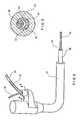
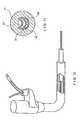
Fig. 1 is a perspective view of a catheter including a rapid exchange channel;Fig. 2 is a cross-sectional view of the catheter ofFig. 1 taken along line 2-2 thereof;Fig. 3 is a cross-sectional view of the catheter with guide wire ofFig. 1 taken along line 3-3 thereof;Fig. 4 is a perspective, partially cross-sectional view of a catheter having a depressable guide wire lumen;Fig. 5 is a cross-sectional view of the catheter ofFig. 4 , taken along line 5-5 thereof;Fig. 6 is a perspective view of the catheter ofFig. 4 rotated about a longitudinal axis thereof with respect toFig. 4 ;Fig. 7 is a cross-sectional view of the catheter ofFig. 6 , taken along line 7-7 thereof;Fig. 8 is a perspective view of a catheter according to the present invention received within a working channel of an endoscope;Fig. 9 is a cross-sectional view of the endoscope and catheter ofFig. 8 taken along line 9-9 thereof;Fig. 10 is a partially cross-sectional view of the endoscope ofFig. 8 ; andFig. 11 is a cross-sectional view of the endoscope ofFig. 8 when no guide wire extends through the endoscope.- Treating an abnormal pathology within a patient's biliary tree may involve introducing an endoscope into the mouth of the patient and guiding the endoscope through the patient's alimentary tract until an opening at a distal end of the endoscope is proximate an area to receive treatment. Those skilled in the art will understand that, although the catheters and methods of use described herein are illustrated in conjunction with procedures for accessing the biliary tree, these catheters may be employed, or modified for employment (e.g., by changing diameter, length, etc.) in procedures to be performed in any body lumen.
- For visualization or treatment of a target area within a body lumen, e.g., an area within the biliary tree, the distal end of an endoscope may be positioned proximate the papilla of vater leading to the common bile duct and the pancreatic duct. A catheter may then be guided through the lumen (e.g., a working channel) of the endoscope until a distal tip of the catheter emerges from an opening at the distal end of the endoscope. The catheter may then be advanced through the sphincter into the bile duct. A guide wire may then be advanced through the catheter, as will be described in more detail below, into the bile duct and guided using, e.g., fluoroscopy, to a target area to be treated by the catheter. The catheter is then advanced along the guide wire to the target area.
- As shown in
Figs. 1- 11 , one suchrapid exchange catheter 30 includes aguide wire lumen 60 including adepressable portion 42 wherein an outer wall of thecatheter 30 over theguide wire lumen 60 is collapsed radially inwardly as shown inFigs. 4, 5 and 7 . As shown inFig. 5 , partially circumferential slits 52', 54', are formed in an outer wall of thecatheter 30 at the depressable portion ends so that openings are formed to theguide wire lumen 60 at thedepressable portion ends guide wire 36 to be inserted into or removed from theguide wire lumen 60 at the depressable portiondistal end 54, a described in more detail below. Those skilled in the art will understand that, alternatively, thedepressable portion 42 may be formed with an opening only at thedistal end 54 as theguide wire 36 enters theguide wire lumen 60 only through thedistal end 54. Thus, in a catheter of this type the slit 52' need not be formed at theend 52. Furthermore, those skilled in the art will understand that it would be possible to form an opening to theguide wire lumen 60 at any place in the channel 42'. However, it is preferable to place this opening at thedistal end 54 thereof so that the interior space of the catheter is not compromised by both thedepressed portion 42 and a guide wire received therein at the same longitudinal position. - The
guide wire 36 may be received within a channel 42' formed by thedepressable portion 42 so that, even though theguide wire 36 extends outside thecatheter 30 along thedepressable portion 42, an outer diameter of this assembly is no greater than an outer diameter of thecatheter 30 alone. As shown inFig. 8 , thecatheter 30 and theguide wire 36 may fit comfortable within the working channel of anendoscope 70. Thus, the depressable portionproximal end 52 is preferably located on a portion of thecatheter 30 which will remain proximally outside theendoscope 70 during use. - The fact that the
guide wire 36 is received only within a distal portion of thecatheter 30 allows thecatheter assembly 30 to be exchanged rapidly without the need for guide wire extenders or other devices as described more fully below. - More specifically,
Figs. 1 - 11 show acatheter 30 including acatheter hub assembly 32 with aguide wire 36 passing through aguidewire lumen 60 which extends through a distal portion thereof. That is, theguide wire 36 extends within thecatheter 30 from the depressable portiondistal end 54 to adistal end 46 of thecatheter 30. Thecatheter 30 includes ashaft 38 which has aproximal end 40, adepressable portion 42, adistal tip region 44 and various lumens described in greater detail below. Thecatheter hub assembly 32 is operably connected to aproximal end 40 of theshaft 38. Thecatheter hub assembly 32 may preferably be configured to couple to ancillary devices allowing access to the lumens within theshaft 38. - In a first embodiment, the
shaft 38 may be a generally tubular member having a generally uniform outer shape at theproximal end 40. As would be understood by those of skill in the art, theshaft 38 may preferably be sized for slidable passage through, for example, the working channel of anendoscope 70 or through a body lumen. Theshaft 38 may preferably be formed in an extrusion process, and may be formed, for example, of a polymeric material. In one embodiment, the preferred polymeric material is polytetrafluoroethylene, polyether block amid, nylon or a combination or blend of these. Catheters that are contemplated include, but are not limited to, cannulas, sphincterotomes, cytology devices, and devices for stone retrieval and stent placement. - As shown in
Fig. 1 , theshaft 38 may further include adistal taper 48 that tapers to thedistal tip region 44. Additionally, thedistal tip region 44 may, for example, include high contrast, color-codeddistal markers 50. Finally, thedistal end 46 may be radiopaque for fluoroscopic visualization of thedistal tip region 44 during a catheter procedure. - In this embodiment, the
guide wire lumen 60 extends through thecatheter 30 from theproximal end 40 to thedistal end 46 thereof. Thedepressable portion 42 is formed over a portion of theguide wire lumen 60 extending between the depressable portion proximal and distal ends 52, 54, respectively. In this embodiment, thedepressable portion 42 is moveable between an expanded configuration in which an outer wall of thelumen 60 is extended radially to form a substantially continuous surface with the rest of thecatheter 30 and a depressed configuration in which the outer wall is collapsed into thelumen 60 to form a channel 42' in which a portion of theguide wire 36 may be received. That is, thecatheter 30 is preferably formed so that, when in an unstressed state (i.e., with noguide wire 36 passing through the lumen 60), thedepressable portion 42 is in the depressed configuration. If aguide wire 36 is inserted into theguide wire lumen 60 from theproximal end 40 to enter that portion of thelumen 60 within thedepressable portion 42, theguide wire 36 urges the outer wall of thecatheter 30 outward to the expanded configuration. - Those skilled in the art will understand that, if the
catheter 30 is not to be used in procedures where guide wire exchanges are contemplated, theguide wire lumen 60 does not need to extend proximally of the depressable portiondistal end 54. This would mean that the slit 52' need not be included in such acatheter 30. Furthermore, such acatheter 30 would not need adepressable portion 42 movable between depressed and expanded configurations as noguide wire 36 would ever be received beneath thedepressable portion 42 to move it to the expanded configuration. Thus, thedepressable portion 42 of such acatheter 30 could be molded permanently in the depressed configuration. - As described above, although the
proximal end 52 may be located at any location distal of theproximale end 40 of theshaft 38, it is preferably located at a portion of thecatheter 30 which remains proximally outside theendoscope 70 during use. Thedistal end 54 may be located at any point distal of the depressable portionproximal end 52, but may preferably be located between 10 and 40 cm from thedistal end 46 of thecatheter shaft 38. Thedistal opening 54 may more preferably be located between 20 and 30cm and, most preferably, approximately 25cm from thedistal end 46. As shown inFigs. 2 and 3 , with the exception of the slits 52' and 54', theguide wire lumen 60 of thecatheter 30 ofFig. 1 is completely sealed from an outside of thecatheter 30. - The
catheter 30 according to this exemplary embodiment also includesancillary lumens ancillary lumens proximal end 40 and thedistal end 46 of theshaft 38 so that they may be used, for example, as injection lumens, allowing for high contrast media flow capability for bubble-free opacification and for visualization of a desired anatomical region. Additionally or alternatively, theancillary lumens - As described above, the
catheter 30 ofFig. 1 includes aguide wire lumen 60 that allows rapid exchange of thecatheter 30 or theguide wire 36 when an alternative catheter or guide wire is necessary during a medical procedure. Thus, shorter length guide wires may be used since theguide wire 36 does not need to pass through the entire length of the shaft. When thecatheter 30 is to be exchanged, an operator grasps the portion of theguide wire 36 extending out of theendoscope 70 and withdraws thecatheter 30 proximally therealong while maintaining the position of theguide wire 36 at the target location. As only a short portion of theguide wire 36 is received within thecatheter 30, the user may maintain his grasp on theguide wire 36 until thedistal end 46 of the catheter exits the proximal end of theendoscope 70. At this time, the user may grasp the portion of theguide wire 36 extending distally from thedistal end 46 and completely remove thecatheter 30 from theguide wire 36 without ever letting go of theguide wire 36 and without resorting to guide wire extenders, etc. - Of course, if desired, the
guide wire 36 may also run through the entire length of thelumen 60 from theproximal end 40 of thecatheter 30 to thedistal end 46 thereof, for example, if thecatheter 30 is maintained in place while theguide wire 36 is removed therefrom. Anew guide wire 36 may then be inserted through the entire length of thecatheter 30 moving thedepressable portion 42 from the collapsed to the expanded configuration. However, after this has been done, the effectiveness of the rapid exchange features of thiscatheter 30 may be reduced. - As shown in
Fig. 4 , the channel 42' merges with theguide wire lumen 60 at both ends thereof and may be used as an enhy point for theguide wire 36. Those skilled in the art will understand that only the depressable portiondistal end 54 needs to be open to theguide wire lumen 60 as theguide wire 36 will preferably extend from theguide wire lumen 60 through the slit 54' (which, when thecatheter 30 is in the depressed configuration, forms an opening) into the channel 42'. As described above, thecatheter 30 may be formed so that thedepressable portion 42 remains in the depressed configuration unless aguide wire 36 is received within thedepressable portion 42 of thelumen 36 pushing the outer wall of thecatheter 30 outward. Those skilled in the art will understand that the channel 42' may be formed by mechanically deforming or crushing theshaft 38 and may be induced to remain in this position by, for example, heating the designated area of theshaft 38 where the channel 42' is sought. The heat may make the polymeric material of which theshaft 38 is composed more malleable allowing thecatheter 30 to retain the shape including channel 42'. - In addition, as described above, partially circumferential slits 52', 54', may be cut at the ends of the channel 42' substantially perpendicular to the longitudinal axis of the
catheter 30 to allow the proximal and distal ends of thedepressable portion 42 to separate from adjacent portions of thecatheter 30 when the catheter is moved to the depressed configuration.Fig. 6 shows a cross-sectional view of thedepressable portion 42 of theshaft 38 in the expanded configuration whileFig. 7 shows thecatheter 30 in the depressed configuration. Alternatively, as shown inFig. 11 , a catheter 30' may be formed with achannel 42" which is permanently in the collapsed configuration. - As would be understood by those of skill in the art, the viscosity of bodily fluids, such as bile, allows them to travel through the working channel of the endoscope, along the outer walls of catheters under capillary action causing risk of contamination if these fluids escape. To guard against this, a rubber seal is often placed around the
catheter 30 within the working channel. As would be understood by those of skill in the art, in contrast with catheters having discontinuities in their outer skins due to channels opening therethrough, the smooth surface of the outer wall of thecatheter 30 in thedepressed portion 42 with only rounded surfaces allows for a better seal to be obtained therearound. - Another advantage of the
depressable portion 42 is that it increases the columnar strength of theshaft 38 as compared to catheters which have longitudinally extending channels cut through their outer surfaces. As the channel 42' of thecatheter 30 is formed without removing any material from the outer surface thereof, the column strength of thecatheter 30 is maintained substantially equivalent to that of standard catheters with no rapid exchange features. As shown inFig. 7 , theshaft 38 containsancillary lumens depressed lumen 61. - As described above, the channel 42' may be used as an entry point for a
guide wire 36, as theguide wire 36 may be inserted into theguide wire lumen 60 via thedistal opening 54. As also described above, the channel 42' allows for rapid exchange of thecatheter 30 when an alternative catheter is necessary during a medical procedure. Shorter length guide wires may be used sinceguide wire 36 does not pass through the shaftproximal end 40 andhub assembly 32, but rather exits theshaft 38 at a location at least as removed distally from theproximal end 40 as thedistal opening 54. - The present invention may be incorporated into most existing conventional catheter procedures since, with the exception of guide wire exchange, the catheter according to this invention is not substantially different in operation from these known catheters.
- In one possible endoscopic procedure, an endoscope is first introduced into a patient's mouth and is guided down the esophagus, through the stomach, past the pyloric sphincter of the stomach and into the duodenum. The endoscope is then guided through the alimentary canal until a distal end of the endoscope is proximate to a target area that requires treatment. For instance, in an endoscopic biliary procedure, the endoscope is guided into the duodenum until the opening at the distal end of the endoscope is proximate the papilla of vater.
- Once the endoscope has been properly positioned within the patient, the
catheter 30 is inserted into the endoscope and advanced therethrough to exit at the distal end of the endoscope. Aguide wire 36 is then inserted into theguide wire lumen 60 of acatheter 30 and thecatheter 30 and theguide wire 36 are then advanced through the sphincter into the bile duct. Theguide wire 36 is then advanced through theguide wire lumen 60 to exit thedistal end 46 of thecatheter 30 and enter the bile duct. As would be understood by those of skill in the art, theguide wire 36 may then be advanced through the bile duct to the target area and theshaft 38 may then be advanced over theguide wire 36 to the target area. - As would be understood by those of skill in the art, once the
guide wire 36 has been positioned at the target area, various catheter procedures may be performed. For example, contrast media, such as radiopaque dye, may be injected thereto via theancillary lumens catheter 30 may need to be exchanged. - At this point, the physician simply draws the
catheter 30 proximally along theguide wire 36 while grasping the proximal end of theguide wire 36. When the distal end of thecatheter 30 exits the body, the physician may grasp the portion of theguide wire 36 extending distally of thecatheter 30 and remove thecatheter 30 completely from theguide wire 36. The loading process described above may then be repeated for thenew catheter 30 to be used. If, however, the physician wishes to exchange theguide wire 36 while maintaining thecatheter 30 in a desired position within the body, the following steps are performed. First, while grasping the proximal end of thecatheter 30, the physician draws theguide wire 36 proximally out of theguide wire lumen 60 and removes it from the body. Then, thenew guide wire 36 is inserted into theproximal opening 52 and is fed through theguide wire lumen 60 through the C-channel 42 so that it deflects the outer wall of thedepressable portion 42 radially outward to allow theguide wire 36 to pass thereunder, past thedistal opening 54 and out of thedistal end 46 of thecatheter 30. - If a
guide wire 36 has been inserted from theproximal end 40 of thecatheter 30, past theproximal opening 52, through thedepressable portion 42 to thedistal end 46 thereof and thiscatheter 30 later needs to be exchanged while maintaining theguide wire 36 in position, the physician grasps the proximal end of theguide wire 36 to maintain it in position and grasps theguide wire 36 through theproximal opening 52 and draws the proximal end of theguide wire 36 distally through the proximal portion of theguide wire lumen 60 while holding the distal portion of theguide wire 36 stationary to maintain the position of the distal end of theguide wire 36. When the proximal end of theguide wire 36 has been removed from theguide wire lumen 60, thecatheter 30 may be drawn proximally from the body while the physician maintains his grasp of theguide wire 36 as it slides out of theproximal opening 52. When the distal end of thecatheter 30 is outside the body, the physician grasps the portion of theguide wire 36 extending distally of the distal end of thecatheter 30 and withdraws thecatheter 30 from theguide wire 36. - It will be understood that this disclosure, in many respects, is only illustrative. Changes may be made in details, particularly in matters of shape, size, material, and arrangement of parts without exceeding the scope of the invention. Accordingly, the scope of the invention is as defined in the language of the appended claims.
Claims (7)
- A rapid exchange catheter (30) extending from a proximal portion (40) to a distal portion (44), wherein the proximal and distal portions are coupled by a medial portion, the catheter (30) comprising:a guide wire lumen (60) extending through the catheter (30) from the proximal portion (40) to the distal portion (44) and extending longitudinally through the distal portion (44) of the catheter (30),
characterized bya guide wire receiving channel (42') formed by a depressed portion (42) of an outer surface of the medial portion, wherein the channel (42') merges with the guide wire lumen at both ends thereof, andwherein the depressed portion (42) extends from the channel distal end (54) proximally to the channel proximal end (52). - The catheter according to claim 1, wherein a depth of the channel is at least as great as a diameter of the guide wire lumen (60).
- The catheter according to claim 1, wherein the channel distal end (54) is between 10 and 40 cm from a distal end (46) of the catheter (30).
- The catheter of claim 3, wherein the channel distal end (54) is between 20 and 30 cm from the distal end (46) of the catheter (30).
- The catheter of claim 4, wherein the channel distal end (54) is approximately 25 cm from the distal end (46) of the catheter (30).
- A rapid exchange catheter system comprising a guide wire and a rapid exchange catheter (30) extending from a proximal portion (40) to a distal portion (44), wherein the proximal and distal portions are coupled by a medial portion, the catheter (30) comprising:a guide wire lumen (60) extending through the catheter (30) from the proximal portion (40) to the distal portion (44) and extending longitudinally through the distal portion (44) of the catheter (30),
characterized bya guide wire receiving channel (42') formed by a depressed portion (42) of an outer surface of the medial portion, wherein the guide wire lumen (60) is open to a channel distal end (46) and wherein a medial portion of the guide wire lumen (60) runs within the medial portion of the catheter (30) adjacent to the depressed portion (42) so that, when the guide wire (36) is received, within the medial portion of the guide wire lumen (60), the depressed portion (42) is moved to an expanded configuration in which the channel is substantially eliminated. - The catheter according to claim 6, wherein the outer wall is biased so that, when no guide wire (36) is received within the medial portion of the guide wire lumen (60), the depressed portion (42) remains in a depressed configuration forming the channel.
Applications Claiming Priority (3)
| Application Number | Priority Date | Filing Date | Title |
|---|---|---|---|
| US10/298,313US7037293B2 (en) | 2002-11-15 | 2002-11-15 | Rapid exchange catheter with depressable channel |
| US298313 | 2002-11-15 | ||
| PCT/US2003/033570WO2004045699A1 (en) | 2002-11-15 | 2003-10-22 | Rapid exchange catheter with depressable channel |
Publications (2)
| Publication Number | Publication Date |
|---|---|
| EP1578468A1 EP1578468A1 (en) | 2005-09-28 |
| EP1578468B1true EP1578468B1 (en) | 2013-04-03 |
Family
ID=32297412
Family Applications (1)
| Application Number | Title | Priority Date | Filing Date |
|---|---|---|---|
| EP03811603AExpired - LifetimeEP1578468B1 (en) | 2002-11-15 | 2003-10-22 | Rapid exchange catheter with depressable channel |
Country Status (6)
| Country | Link |
|---|---|
| US (3) | US7037293B2 (en) |
| EP (1) | EP1578468B1 (en) |
| JP (1) | JP4599166B2 (en) |
| AU (1) | AU2003301998B2 (en) |
| CA (1) | CA2471806C (en) |
| WO (1) | WO2004045699A1 (en) |
Families Citing this family (47)
| Publication number | Priority date | Publication date | Assignee | Title |
|---|---|---|---|---|
| US7037293B2 (en)* | 2002-11-15 | 2006-05-02 | Boston Scientific Scimed, Inc. | Rapid exchange catheter with depressable channel |
| US8252014B2 (en) | 2004-03-03 | 2012-08-28 | Innovational Holdings Llc. | Rapid exchange balloon catheter with braided shaft |
| US8878924B2 (en) | 2004-09-24 | 2014-11-04 | Vivid Medical, Inc. | Disposable microscope and portable display |
| US9033870B2 (en)* | 2004-09-24 | 2015-05-19 | Vivid Medical, Inc. | Pluggable vision module and portable display for endoscopy |
| US8858425B2 (en) | 2004-09-24 | 2014-10-14 | Vivid Medical, Inc. | Disposable endoscope and portable display |
| US8827899B2 (en)* | 2004-09-24 | 2014-09-09 | Vivid Medical, Inc. | Disposable endoscopic access device and portable display |
| US7901367B2 (en)* | 2005-06-30 | 2011-03-08 | Cook Incorporated | Wire guide advancement system |
| WO2008006111A2 (en)* | 2006-07-07 | 2008-01-10 | The Spectranetics Corporation | Single lumen support catheter for rapid exchange and over the wire use |
| US8167894B2 (en) | 2006-08-09 | 2012-05-01 | Coherex Medical, Inc. | Methods, systems and devices for reducing the size of an internal tissue opening |
| US9220487B2 (en)* | 2006-08-09 | 2015-12-29 | Coherex Medical, Inc. | Devices for reducing the size of an internal tissue opening |
| US8529597B2 (en) | 2006-08-09 | 2013-09-10 | Coherex Medical, Inc. | Devices for reducing the size of an internal tissue opening |
| US20090054874A1 (en)* | 2007-08-23 | 2009-02-26 | C. R. Bard, Inc. | Multi-lumen catheter including a lumen having a variable cross sectional area |
| US20090137872A1 (en)* | 2007-11-27 | 2009-05-28 | Tyco Healthcare Group Lp | Method and Apparatus for Controlling Endoscopic Instruments |
| US8876704B2 (en) | 2008-01-14 | 2014-11-04 | Boston Scientific Scimed, Inc. | Medical device |
| US8343041B2 (en) | 2008-05-19 | 2013-01-01 | Boston Scientific Scimed, Inc. | Integrated locking device with passive sealing |
| US8388521B2 (en)* | 2008-05-19 | 2013-03-05 | Boston Scientific Scimed, Inc. | Integrated locking device with active sealing |
| US20110264098A1 (en)* | 2010-02-26 | 2011-10-27 | Cobbs Charles S | Minimally invasive systems, devices, and surgical methods for performing arthrodesis in the spine |
| US8591450B2 (en) | 2010-06-07 | 2013-11-26 | Rex Medical L.P. | Dialysis catheter |
| US20120059337A1 (en)* | 2010-09-01 | 2012-03-08 | Eran Eilat | Catheter with asymmetric or collapsible-expandable cross-section |
| JP2012075800A (en)* | 2010-10-05 | 2012-04-19 | Inter Noba Kk | Catheter |
| WO2013070758A2 (en) | 2011-11-09 | 2013-05-16 | Boston Scientific Scimed, Inc. | Guide extension catheter |
| US9278198B2 (en) | 2011-12-28 | 2016-03-08 | Boston Scientific Scimed, Inc. | Biliary access catheter system and methods for accessing the biliary tree |
| US9126013B2 (en)* | 2012-04-27 | 2015-09-08 | Teleflex Medical Incorporated | Catheter with adjustable guidewire exit position |
| CN104812420B (en)* | 2012-08-17 | 2017-09-22 | 波士顿科学西美德公司 | Guiding extension conduit |
| EP3096830B1 (en)* | 2014-01-20 | 2025-06-04 | Boston Scientific Medical Device Limited | Collapsible tip re-entry catheter |
| ES2975734T3 (en) | 2015-01-29 | 2024-07-12 | Becton Dickinson Co | Integrated Quick Insert Catheter |
| WO2018075700A1 (en) | 2016-10-18 | 2018-04-26 | Boston Scientific Scimed, Inc. | Guide extension catheter |
| IT201700027573A1 (en)* | 2017-03-13 | 2018-09-13 | Gioachino Coppi | GUIDE FOR THE INTRODUCTION OF AT LEAST ONE SURGICAL INSTRUMENT INSIDE AN ORGANIC CAVITY |
| WO2019033006A1 (en) | 2017-08-11 | 2019-02-14 | Boston Scientific Scimed, Inc. | Biopsy cap for use with endoscope |
| US11938286B2 (en) | 2018-02-26 | 2024-03-26 | Cti Vascular Ag | Usable-length-selectable catheter to treat vascular pathologies |
| WO2020017024A1 (en)* | 2018-07-20 | 2020-01-23 | オリンパス株式会社 | Guide wire holding instrument and method for inserting guide wire holding instrument |
| US11890429B2 (en) | 2019-09-10 | 2024-02-06 | Bard Access Systems, Inc. | Rapidly inserted central catheter and methods thereof |
| BR112022005254A2 (en) | 2019-09-24 | 2022-06-14 | Bard Access Systems Inc | Acute central venous catheter and peripherally inserted venous catheter integrated |
| WO2021081434A1 (en) | 2019-10-25 | 2021-04-29 | Bard Access Systems, Inc. | Guidewire-management devices and methods thereof |
| CA3168492A1 (en) | 2020-01-23 | 2021-07-29 | Bard Access Systems, Inc. | Splitable catheter docking station system |
| CN113384798A (en) | 2020-03-13 | 2021-09-14 | 巴德阿克塞斯系统股份有限公司 | Guide wire management device and method thereof |
| KR20220153062A (en) | 2020-03-13 | 2022-11-17 | 바드 액세스 시스템즈, 인크. | GUIDEWIRE-MANAGEMENT DEVICES AND METHODS THEREOF |
| EP4135819A1 (en) | 2020-04-23 | 2023-02-22 | Bard Access Systems, Inc. | Rapidly insertable central catheters including catheter assemblies |
| WO2021236950A1 (en) | 2020-05-21 | 2021-11-25 | Bard Access Systems, Inc. | Rapidly insertable central catheters including catheter assemblies |
| CA3186461A1 (en) | 2020-06-29 | 2022-01-06 | Bard Access Systems, Inc. | Rapidly insertable central catheters including assemblies |
| AU2021303150B2 (en) | 2020-06-29 | 2025-10-02 | Bard Access Systems, Inc. | Rapidly insertable central catheters including catheter assemblies and methods thereof |
| AU2021371314B2 (en) | 2020-10-28 | 2025-09-25 | Bard Access Systems, Inc. | Catheter placement system with stiffening system |
| US11351047B2 (en)* | 2020-11-03 | 2022-06-07 | Brian Thorson | Devices and methods for stent graft extraction |
| AU2021400331B2 (en) | 2020-12-17 | 2025-09-25 | Bard Access Systems, Inc. | Rapidly insertable central catheters and assemblies |
| EP4259254A1 (en) | 2020-12-21 | 2023-10-18 | Bard Access Systems, Inc. | Optimized structural support in catheter insertion systems |
| EP4259256A1 (en) | 2020-12-21 | 2023-10-18 | Bard Access Systems, Inc. | Fluid path optimization in catheter insertion systems |
| WO2025133945A1 (en)* | 2023-12-22 | 2025-06-26 | Gentile Carmine Savio | Endoscope with disposable operating channel |
Citations (1)
| Publication number | Priority date | Publication date | Assignee | Title |
|---|---|---|---|---|
| US5334154A (en)* | 1992-08-04 | 1994-08-02 | Advanced Cardiovascular Systems, Inc. | Perfusion type dilatation catheter having perfusion ports with depressed proximal edges |
Family Cites Families (16)
| Publication number | Priority date | Publication date | Assignee | Title |
|---|---|---|---|---|
| US6821287B1 (en)* | 1991-05-24 | 2004-11-23 | Advanced Cardiovascular Systems, Inc. | Multi-mode vascular catheter system |
| US5389087A (en)* | 1991-09-19 | 1995-02-14 | Baxter International Inc. | Fully exchangeable over-the-wire catheter with rip seam and gated side port |
| US5324269A (en)* | 1991-09-19 | 1994-06-28 | Baxter International Inc. | Fully exchangeable dual lumen over-the-wire dilatation catheter with rip seam |
| JPH06511409A (en) | 1992-05-11 | 1994-12-22 | メディカル イノベイションズ コーポレイション | Improved biliary catheter |
| US5300025A (en)* | 1992-09-30 | 1994-04-05 | Advanced Cardiovascular Systems, Inc. | Dilatation catheter having a coil supported inflation lumen |
| US5320602A (en) | 1993-05-14 | 1994-06-14 | Wilson-Cook Medical, Inc. | Peel-away endoscopic retrograde cholangio pancreatography catheter and a method for using the same |
| US5336184A (en)* | 1993-07-15 | 1994-08-09 | Teirstein Paul S | Rapid exchange catheter |
| US5489271A (en)* | 1994-03-29 | 1996-02-06 | Boston Scientific Corporation | Convertible catheter |
| US6054229A (en) | 1996-07-19 | 2000-04-25 | Ztek Corporation | System for electric generation, heating, cooling, and ventilation |
| US6007522A (en) | 1996-09-13 | 1999-12-28 | Boston Scientific Corporation | Single operator exchange biliary catheter |
| US6096009A (en)* | 1996-09-13 | 2000-08-01 | Boston Scientific Corporation | Guidewire and catheter locking device and method |
| US6520951B1 (en) | 1996-09-13 | 2003-02-18 | Scimed Life Systems, Inc. | Rapid exchange catheter with detachable hood |
| US6312374B1 (en) | 1997-03-06 | 2001-11-06 | Progenix, Llc | Radioactive wire placement catheter |
| US6450987B1 (en) | 2001-02-01 | 2002-09-17 | Innercool Therapies, Inc. | Collapsible guidewire lumen |
| US7163524B2 (en) | 2002-02-27 | 2007-01-16 | Terumo Kabushiki Kaisha | Catheter |
| US7037293B2 (en)* | 2002-11-15 | 2006-05-02 | Boston Scientific Scimed, Inc. | Rapid exchange catheter with depressable channel |
- 2002
- 2002-11-15USUS10/298,313patent/US7037293B2/ennot_activeExpired - Lifetime
- 2003
- 2003-10-22CACA2471806Apatent/CA2471806C/ennot_activeExpired - Fee Related
- 2003-10-22JPJP2004553466Apatent/JP4599166B2/ennot_activeExpired - Fee Related
- 2003-10-22EPEP03811603Apatent/EP1578468B1/ennot_activeExpired - Lifetime
- 2003-10-22WOPCT/US2003/033570patent/WO2004045699A1/enactiveApplication Filing
- 2003-10-22AUAU2003301998Apatent/AU2003301998B2/ennot_activeCeased
- 2006
- 2006-03-02USUS11/366,739patent/US20060178654A1/ennot_activeAbandoned
- 2008
- 2008-10-20USUS12/254,425patent/US8298178B2/ennot_activeExpired - Fee Related
Patent Citations (1)
| Publication number | Priority date | Publication date | Assignee | Title |
|---|---|---|---|---|
| US5334154A (en)* | 1992-08-04 | 1994-08-02 | Advanced Cardiovascular Systems, Inc. | Perfusion type dilatation catheter having perfusion ports with depressed proximal edges |
Also Published As
| Publication number | Publication date |
|---|---|
| AU2003301998B2 (en) | 2008-12-18 |
| US20040097904A1 (en) | 2004-05-20 |
| AU2003301998A1 (en) | 2004-06-15 |
| CA2471806A1 (en) | 2004-06-03 |
| JP4599166B2 (en) | 2010-12-15 |
| EP1578468A1 (en) | 2005-09-28 |
| CA2471806C (en) | 2011-09-13 |
| US20060178654A1 (en) | 2006-08-10 |
| US8298178B2 (en) | 2012-10-30 |
| US20090099550A1 (en) | 2009-04-16 |
| US7037293B2 (en) | 2006-05-02 |
| WO2004045699A1 (en) | 2004-06-03 |
| JP2006506170A (en) | 2006-02-23 |
Similar Documents
| Publication | Publication Date | Title |
|---|---|---|
| EP1578468B1 (en) | Rapid exchange catheter with depressable channel | |
| US10549069B2 (en) | Catheter with formed guide wire ramp | |
| US5921971A (en) | Single operator exchange biliary catheter | |
| US6764484B2 (en) | C-channel to o-channel converter for a single operator exchange biliary catheter |
Legal Events
| Date | Code | Title | Description |
|---|---|---|---|
| PUAI | Public reference made under article 153(3) epc to a published international application that has entered the european phase | Free format text:ORIGINAL CODE: 0009012 | |
| 17P | Request for examination filed | Effective date:20040628 | |
| AK | Designated contracting states | Kind code of ref document:A1 Designated state(s):AT BE BG CH CY CZ DE DK EE ES FI FR GB GR HU IE IT LI LU MC NL PT RO SE SI SK TR | |
| AX | Request for extension of the european patent | Extension state:AL LT LV MK | |
| RAP1 | Party data changed (applicant data changed or rights of an application transferred) | Owner name:BOSTON SCIENTIFIC SCIMED, INC. | |
| DAX | Request for extension of the european patent (deleted) | ||
| 17Q | First examination report despatched | Effective date:20100527 | |
| GRAP | Despatch of communication of intention to grant a patent | Free format text:ORIGINAL CODE: EPIDOSNIGR1 | |
| GRAS | Grant fee paid | Free format text:ORIGINAL CODE: EPIDOSNIGR3 | |
| GRAA | (expected) grant | Free format text:ORIGINAL CODE: 0009210 | |
| AK | Designated contracting states | Kind code of ref document:B1 Designated state(s):AT BE BG CH CY CZ DE DK EE ES FI FR GB GR HU IE IT LI LU MC NL PT RO SE SI SK TR | |
| REG | Reference to a national code | Ref country code:GB Ref legal event code:FG4D | |
| REG | Reference to a national code | Ref country code:CH Ref legal event code:EP Ref country code:AT Ref legal event code:REF Ref document number:604296 Country of ref document:AT Kind code of ref document:T Effective date:20130415 | |
| REG | Reference to a national code | Ref country code:IE Ref legal event code:FG4D | |
| REG | Reference to a national code | Ref country code:DE Ref legal event code:R096 Ref document number:60343693 Country of ref document:DE Effective date:20130606 | |
| REG | Reference to a national code | Ref country code:AT Ref legal event code:MK05 Ref document number:604296 Country of ref document:AT Kind code of ref document:T Effective date:20130403 | |
| PG25 | Lapsed in a contracting state [announced via postgrant information from national office to epo] | Ref country code:SI Free format text:LAPSE BECAUSE OF FAILURE TO SUBMIT A TRANSLATION OF THE DESCRIPTION OR TO PAY THE FEE WITHIN THE PRESCRIBED TIME-LIMIT Effective date:20130403 | |
| REG | Reference to a national code | Ref country code:NL Ref legal event code:VDEP Effective date:20130403 | |
| PG25 | Lapsed in a contracting state [announced via postgrant information from national office to epo] | Ref country code:FI Free format text:LAPSE BECAUSE OF FAILURE TO SUBMIT A TRANSLATION OF THE DESCRIPTION OR TO PAY THE FEE WITHIN THE PRESCRIBED TIME-LIMIT Effective date:20130403 Ref country code:SE Free format text:LAPSE BECAUSE OF FAILURE TO SUBMIT A TRANSLATION OF THE DESCRIPTION OR TO PAY THE FEE WITHIN THE PRESCRIBED TIME-LIMIT Effective date:20130403 Ref country code:BE Free format text:LAPSE BECAUSE OF FAILURE TO SUBMIT A TRANSLATION OF THE DESCRIPTION OR TO PAY THE FEE WITHIN THE PRESCRIBED TIME-LIMIT Effective date:20130403 Ref country code:AT Free format text:LAPSE BECAUSE OF FAILURE TO SUBMIT A TRANSLATION OF THE DESCRIPTION OR TO PAY THE FEE WITHIN THE PRESCRIBED TIME-LIMIT Effective date:20130403 Ref country code:PT Free format text:LAPSE BECAUSE OF FAILURE TO SUBMIT A TRANSLATION OF THE DESCRIPTION OR TO PAY THE FEE WITHIN THE PRESCRIBED TIME-LIMIT Effective date:20130805 Ref country code:GR Free format text:LAPSE BECAUSE OF FAILURE TO SUBMIT A TRANSLATION OF THE DESCRIPTION OR TO PAY THE FEE WITHIN THE PRESCRIBED TIME-LIMIT Effective date:20130704 Ref country code:ES Free format text:LAPSE BECAUSE OF FAILURE TO SUBMIT A TRANSLATION OF THE DESCRIPTION OR TO PAY THE FEE WITHIN THE PRESCRIBED TIME-LIMIT Effective date:20130714 Ref country code:NL Free format text:LAPSE BECAUSE OF FAILURE TO SUBMIT A TRANSLATION OF THE DESCRIPTION OR TO PAY THE FEE WITHIN THE PRESCRIBED TIME-LIMIT Effective date:20130403 | |
| PG25 | Lapsed in a contracting state [announced via postgrant information from national office to epo] | Ref country code:CY Free format text:LAPSE BECAUSE OF FAILURE TO SUBMIT A TRANSLATION OF THE DESCRIPTION OR TO PAY THE FEE WITHIN THE PRESCRIBED TIME-LIMIT Effective date:20130403 Ref country code:BG Free format text:LAPSE BECAUSE OF FAILURE TO SUBMIT A TRANSLATION OF THE DESCRIPTION OR TO PAY THE FEE WITHIN THE PRESCRIBED TIME-LIMIT Effective date:20130703 | |
| PG25 | Lapsed in a contracting state [announced via postgrant information from national office to epo] | Ref country code:DK Free format text:LAPSE BECAUSE OF FAILURE TO SUBMIT A TRANSLATION OF THE DESCRIPTION OR TO PAY THE FEE WITHIN THE PRESCRIBED TIME-LIMIT Effective date:20130403 Ref country code:EE Free format text:LAPSE BECAUSE OF FAILURE TO SUBMIT A TRANSLATION OF THE DESCRIPTION OR TO PAY THE FEE WITHIN THE PRESCRIBED TIME-LIMIT Effective date:20130403 Ref country code:CZ Free format text:LAPSE BECAUSE OF FAILURE TO SUBMIT A TRANSLATION OF THE DESCRIPTION OR TO PAY THE FEE WITHIN THE PRESCRIBED TIME-LIMIT Effective date:20130403 Ref country code:SK Free format text:LAPSE BECAUSE OF FAILURE TO SUBMIT A TRANSLATION OF THE DESCRIPTION OR TO PAY THE FEE WITHIN THE PRESCRIBED TIME-LIMIT Effective date:20130403 | |
| PLBE | No opposition filed within time limit | Free format text:ORIGINAL CODE: 0009261 | |
| STAA | Information on the status of an ep patent application or granted ep patent | Free format text:STATUS: NO OPPOSITION FILED WITHIN TIME LIMIT | |
| PG25 | Lapsed in a contracting state [announced via postgrant information from national office to epo] | Ref country code:RO Free format text:LAPSE BECAUSE OF FAILURE TO SUBMIT A TRANSLATION OF THE DESCRIPTION OR TO PAY THE FEE WITHIN THE PRESCRIBED TIME-LIMIT Effective date:20130403 Ref country code:IT Free format text:LAPSE BECAUSE OF FAILURE TO SUBMIT A TRANSLATION OF THE DESCRIPTION OR TO PAY THE FEE WITHIN THE PRESCRIBED TIME-LIMIT Effective date:20130403 | |
| 26N | No opposition filed | Effective date:20140106 | |
| REG | Reference to a national code | Ref country code:DE Ref legal event code:R097 Ref document number:60343693 Country of ref document:DE Effective date:20140106 | |
| PG25 | Lapsed in a contracting state [announced via postgrant information from national office to epo] | Ref country code:MC Free format text:LAPSE BECAUSE OF FAILURE TO SUBMIT A TRANSLATION OF THE DESCRIPTION OR TO PAY THE FEE WITHIN THE PRESCRIBED TIME-LIMIT Effective date:20130403 | |
| REG | Reference to a national code | Ref country code:CH Ref legal event code:PL | |
| PG25 | Lapsed in a contracting state [announced via postgrant information from national office to epo] | Ref country code:CH Free format text:LAPSE BECAUSE OF NON-PAYMENT OF DUE FEES Effective date:20131031 Ref country code:LI Free format text:LAPSE BECAUSE OF NON-PAYMENT OF DUE FEES Effective date:20131031 | |
| REG | Reference to a national code | Ref country code:DE Ref legal event code:R081 Ref document number:60343693 Country of ref document:DE Owner name:BOSTON SCIENTIFIC LIMITED, BM Free format text:FORMER OWNER: SCIMED LIFE SYSTEMS, INC., MAPLE GROVE, MINN., US Effective date:20130411 Ref country code:DE Ref legal event code:R081 Ref document number:60343693 Country of ref document:DE Owner name:BOSTON SCIENTIFIC LIMITED, BM Free format text:FORMER OWNER: BOSTON SCIENTIFIC SCIMED, INC., MARPLE GROVE, MINN., US Effective date:20150202 Ref country code:DE Ref legal event code:R081 Ref document number:60343693 Country of ref document:DE Owner name:BOSTON SCIENTIFIC LIMITED, BM Free format text:FORMER OWNER: BOSTON SCIENTIFIC SCIMED, INC., MAPLE GROVE, MINN., US Effective date:20150202 | |
| PG25 | Lapsed in a contracting state [announced via postgrant information from national office to epo] | Ref country code:TR Free format text:LAPSE BECAUSE OF FAILURE TO SUBMIT A TRANSLATION OF THE DESCRIPTION OR TO PAY THE FEE WITHIN THE PRESCRIBED TIME-LIMIT Effective date:20130403 | |
| PG25 | Lapsed in a contracting state [announced via postgrant information from national office to epo] | Ref country code:LU Free format text:LAPSE BECAUSE OF NON-PAYMENT OF DUE FEES Effective date:20131022 Ref country code:HU Free format text:LAPSE BECAUSE OF FAILURE TO SUBMIT A TRANSLATION OF THE DESCRIPTION OR TO PAY THE FEE WITHIN THE PRESCRIBED TIME-LIMIT; INVALID AB INITIO Effective date:20031022 | |
| REG | Reference to a national code | Ref country code:FR Ref legal event code:PLFP Year of fee payment:14 | |
| REG | Reference to a national code | Ref country code:FR Ref legal event code:PLFP Year of fee payment:15 | |
| REG | Reference to a national code | Ref country code:FR Ref legal event code:PLFP Year of fee payment:16 | |
| PGFP | Annual fee paid to national office [announced via postgrant information from national office to epo] | Ref country code:FR Payment date:20180913 Year of fee payment:16 | |
| PGFP | Annual fee paid to national office [announced via postgrant information from national office to epo] | Ref country code:GB Payment date:20181017 Year of fee payment:16 | |
| GBPC | Gb: european patent ceased through non-payment of renewal fee | Effective date:20191022 | |
| PG25 | Lapsed in a contracting state [announced via postgrant information from national office to epo] | Ref country code:FR Free format text:LAPSE BECAUSE OF NON-PAYMENT OF DUE FEES Effective date:20191031 Ref country code:GB Free format text:LAPSE BECAUSE OF NON-PAYMENT OF DUE FEES Effective date:20191022 | |
| REG | Reference to a national code | Ref country code:DE Ref legal event code:R081 Ref document number:60343693 Country of ref document:DE Owner name:BOSTON SCIENTIFIC MEDICAL DEVICE LIMITED, IE Free format text:FORMER OWNER: BOSTON SCIENTIFIC LIMITED, HAMILTON, BM | |
| PGFP | Annual fee paid to national office [announced via postgrant information from national office to epo] | Ref country code:IE Payment date:20210923 Year of fee payment:19 | |
| PGFP | Annual fee paid to national office [announced via postgrant information from national office to epo] | Ref country code:DE Payment date:20210914 Year of fee payment:19 | |
| REG | Reference to a national code | Ref country code:DE Ref legal event code:R119 Ref document number:60343693 Country of ref document:DE | |
| PG25 | Lapsed in a contracting state [announced via postgrant information from national office to epo] | Ref country code:DE Free format text:LAPSE BECAUSE OF NON-PAYMENT OF DUE FEES Effective date:20230503 | |
| PG25 | Lapsed in a contracting state [announced via postgrant information from national office to epo] | Ref country code:IE Free format text:LAPSE BECAUSE OF NON-PAYMENT OF DUE FEES Effective date:20221022 |