EP1577319B1 - Protein purification with prefiltering - Google Patents
Protein purification with prefilteringDownload PDFInfo
- Publication number
- EP1577319B1 EP1577319B1EP05251124.3AEP05251124AEP1577319B1EP 1577319 B1EP1577319 B1EP 1577319B1EP 05251124 AEP05251124 AEP 05251124AEP 1577319 B1EP1577319 B1EP 1577319B1
- Authority
- EP
- European Patent Office
- Prior art keywords
- prefilter
- media
- outlet
- central
- pads
- Prior art date
- Legal status (The legal status is an assumption and is not a legal conclusion. Google has not performed a legal analysis and makes no representation as to the accuracy of the status listed.)
- Expired - Lifetime
Links
- 238000001742protein purificationMethods0.000titleclaimsdescription8
- 230000009871nonspecific bindingEffects0.000claimsdescription55
- 239000000463materialSubstances0.000claimsdescription46
- 238000011045prefiltrationMethods0.000claimsdescription45
- 239000012530fluidSubstances0.000claimsdescription30
- 108090000623proteins and genesProteins0.000claimsdescription28
- 102000004169proteins and genesHuman genes0.000claimsdescription28
- 238000000034methodMethods0.000claimsdescription16
- 239000000470constituentSubstances0.000claimsdescription14
- 239000012528membraneSubstances0.000claimsdescription14
- OKTJSMMVPCPJKN-UHFFFAOYSA-NCarbonChemical compound[C]OKTJSMMVPCPJKN-UHFFFAOYSA-N0.000claimsdescription12
- 239000003795chemical substances by applicationSubstances0.000claimsdescription12
- 239000003446ligandSubstances0.000claimsdescription12
- 239000011324beadSubstances0.000claimsdescription9
- 239000002657fibrous materialSubstances0.000claimsdescription8
- 238000001042affinity chromatographyMethods0.000claimsdescription7
- 238000011144upstream manufacturingMethods0.000claimsdescription6
- 238000004891communicationMethods0.000claimsdescription5
- 239000002775capsuleSubstances0.000claimsdescription4
- 150000001450anionsChemical class0.000claimsdescription3
- 150000001768cationsChemical class0.000claimsdescription3
- 230000002209hydrophobic effectEffects0.000claimsdescription3
- 238000012432intermediate storageMethods0.000claimsdescription2
- 230000037361pathwayEffects0.000claimsdescription2
- 239000007788liquidSubstances0.000description16
- 241000894007speciesSpecies0.000description16
- 238000001914filtrationMethods0.000description15
- 239000002245particleSubstances0.000description15
- -1polyethylenePolymers0.000description14
- VYPSYNLAJGMNEJ-UHFFFAOYSA-NSilicium dioxideChemical compoundO=[Si]=OVYPSYNLAJGMNEJ-UHFFFAOYSA-N0.000description11
- 229920001343polytetrafluoroethylenePolymers0.000description10
- 239000004810polytetrafluoroethyleneSubstances0.000description10
- 238000000746purificationMethods0.000description10
- 239000005289controlled pore glassSubstances0.000description9
- 239000012460protein solutionSubstances0.000description9
- 239000004698PolyethyleneSubstances0.000description8
- 241000700605VirusesSpecies0.000description8
- 229920000573polyethylenePolymers0.000description8
- 238000000108ultra-filtrationMethods0.000description8
- 239000000945fillerSubstances0.000description7
- 239000011521glassSubstances0.000description5
- 229920003023plasticPolymers0.000description5
- 239000004033plasticSubstances0.000description5
- 239000000377silicon dioxideSubstances0.000description5
- 239000000243solutionSubstances0.000description5
- PXHVJJICTQNCMI-UHFFFAOYSA-NNickelChemical compound[Ni]PXHVJJICTQNCMI-UHFFFAOYSA-N0.000description4
- 210000004027cellAnatomy0.000description4
- 229920002678cellulosePolymers0.000description4
- 235000010980celluloseNutrition0.000description4
- 238000004587chromatography analysisMethods0.000description4
- 229920000098polyolefinPolymers0.000description4
- 229920005989resinPolymers0.000description4
- 239000011347resinSubstances0.000description4
- 239000004813Perfluoroalkoxy alkaneSubstances0.000description3
- 239000004743PolypropyleneSubstances0.000description3
- 230000027455bindingEffects0.000description3
- 239000003518causticsSubstances0.000description3
- 239000001913celluloseSubstances0.000description3
- 230000014759maintenance of locationEffects0.000description3
- 239000000203mixtureSubstances0.000description3
- 229920011301perfluoro alkoxyl alkanePolymers0.000description3
- 239000012466permeateSubstances0.000description3
- 229920002492poly(sulfone)Polymers0.000description3
- 229920001155polypropylenePolymers0.000description3
- 239000012465retentateSubstances0.000description3
- 238000007789sealingMethods0.000description3
- YHMYGUUIMTVXNW-UHFFFAOYSA-N1,3-dihydrobenzimidazole-2-thioneChemical compoundC1=CC=C2NC(S)=NC2=C1YHMYGUUIMTVXNW-UHFFFAOYSA-N0.000description2
- JWYUFVNJZUSCSM-UHFFFAOYSA-N2-aminobenzimidazoleChemical compoundC1=CC=C2NC(N)=NC2=C1JWYUFVNJZUSCSM-UHFFFAOYSA-N0.000description2
- DAPOMFMFTBUAKL-UHFFFAOYSA-N2-ethylpyridine-3-thiolChemical compoundCCC1=NC=CC=C1SDAPOMFMFTBUAKL-UHFFFAOYSA-N0.000description2
- USVXDODAPOBXCF-UHFFFAOYSA-N2-methyl-1h-benzimidazol-4-amineChemical compoundC1=CC=C2NC(C)=NC2=C1NUSVXDODAPOBXCF-UHFFFAOYSA-N0.000description2
- 239000002033PVDF binderSubstances0.000description2
- 239000004952PolyamideSubstances0.000description2
- 229920000491PolyphenylsulfonePolymers0.000description2
- 101710120037Toxin CcdBProteins0.000description2
- 230000000274adsorptive effectEffects0.000description2
- 229960000074biopharmaceuticalDrugs0.000description2
- 229920002301cellulose acetatePolymers0.000description2
- 239000012501chromatography mediumSubstances0.000description2
- 238000009295crossflow filtrationMethods0.000description2
- 239000000835fiberSubstances0.000description2
- 230000004907fluxEffects0.000description2
- 238000005342ion exchangeMethods0.000description2
- 229910052751metalInorganic materials0.000description2
- 239000002184metalSubstances0.000description2
- 229910052759nickelInorganic materials0.000description2
- 229920001778nylonPolymers0.000description2
- 229920002647polyamidePolymers0.000description2
- 229920000728polyesterPolymers0.000description2
- 229920002981polyvinylidene fluoridePolymers0.000description2
- 239000011148porous materialSubstances0.000description2
- 125000006850spacer groupChemical group0.000description2
- 229910001220stainless steelInorganic materials0.000description2
- 239000010935stainless steelSubstances0.000description2
- 239000000126substanceSubstances0.000description2
- 239000000758substrateSubstances0.000description2
- 229920000936AgarosePolymers0.000description1
- 229910001369BrassInorganic materials0.000description1
- 229910000906BronzeInorganic materials0.000description1
- VYZAMTAEIAYCRO-UHFFFAOYSA-NChromiumChemical compound[Cr]VYZAMTAEIAYCRO-UHFFFAOYSA-N0.000description1
- RYGMFSIKBFXOCR-UHFFFAOYSA-NCopperChemical compound[Cu]RYGMFSIKBFXOCR-UHFFFAOYSA-N0.000description1
- 229920000742CottonPolymers0.000description1
- 229920001780ECTFEPolymers0.000description1
- 102000007474Multiprotein ComplexesHuman genes0.000description1
- 108010085220Multiprotein ComplexesProteins0.000description1
- 239000004642PolyimideSubstances0.000description1
- RTAQQCXQSZGOHL-UHFFFAOYSA-NTitaniumChemical compound[Ti]RTAQQCXQSZGOHL-UHFFFAOYSA-N0.000description1
- 239000000853adhesiveSubstances0.000description1
- 230000001070adhesive effectEffects0.000description1
- 229910045601alloyInorganic materials0.000description1
- 239000000956alloySubstances0.000description1
- 229910052782aluminiumInorganic materials0.000description1
- XAGFODPZIPBFFR-UHFFFAOYSA-NaluminiumChemical compound[Al]XAGFODPZIPBFFR-UHFFFAOYSA-N0.000description1
- 239000012062aqueous bufferSubstances0.000description1
- 239000005388borosilicate glassSubstances0.000description1
- 239000010951brassSubstances0.000description1
- 239000010974bronzeSubstances0.000description1
- 239000000872bufferSubstances0.000description1
- 150000001720carbohydratesChemical class0.000description1
- 235000014633carbohydratesNutrition0.000description1
- 210000002421cell wallAnatomy0.000description1
- 210000003850cellular structureAnatomy0.000description1
- 238000005119centrifugationMethods0.000description1
- 239000000919ceramicSubstances0.000description1
- 238000013375chromatographic separationMethods0.000description1
- 239000011651chromiumSubstances0.000description1
- 229910052804chromiumInorganic materials0.000description1
- 238000004140cleaningMethods0.000description1
- 239000000084colloidal systemSubstances0.000description1
- 239000002131composite materialSubstances0.000description1
- 150000001875compoundsChemical class0.000description1
- 229920001577copolymerPolymers0.000description1
- 239000010949copperSubstances0.000description1
- 229910052802copperInorganic materials0.000description1
- KUNSUQLRTQLHQQ-UHFFFAOYSA-Ncopper tinChemical compound[Cu].[Sn]KUNSUQLRTQLHQQ-UHFFFAOYSA-N0.000description1
- 238000009826distributionMethods0.000description1
- 238000001035dryingMethods0.000description1
- 238000010828elutionMethods0.000description1
- 239000011152fibreglassSubstances0.000description1
- 229920002313fluoropolymerPolymers0.000description1
- 239000004811fluoropolymerSubstances0.000description1
- 239000012535impuritySubstances0.000description1
- 230000001788irregularEffects0.000description1
- 230000002427irreversible effectEffects0.000description1
- 150000002632lipidsChemical class0.000description1
- 150000002739metalsChemical class0.000description1
- 239000004745nonwoven fabricSubstances0.000description1
- 239000004417polycarbonateSubstances0.000description1
- 229920000515polycarbonatePolymers0.000description1
- 229920006393polyether sulfonePolymers0.000description1
- 229920001721polyimidePolymers0.000description1
- 229920000642polymerPolymers0.000description1
- 229920002451polyvinyl alcoholPolymers0.000description1
- 235000019422polyvinyl alcoholNutrition0.000description1
- 229920000915polyvinyl chloridePolymers0.000description1
- 239000000843powderSubstances0.000description1
- 230000002028prematureEffects0.000description1
- 239000000047productSubstances0.000description1
- 230000001681protective effectEffects0.000description1
- 239000002990reinforced plasticSubstances0.000description1
- 230000000717retained effectEffects0.000description1
- 238000005070samplingMethods0.000description1
- 150000004760silicatesChemical class0.000description1
- 239000002904solventSubstances0.000description1
- 238000003860storageMethods0.000description1
- 230000003319supportive effectEffects0.000description1
- 229920001897terpolymerPolymers0.000description1
- 229920001169thermoplasticPolymers0.000description1
- 229920005992thermoplastic resinPolymers0.000description1
- 239000004416thermosoftening plasticSubstances0.000description1
- 239000010936titaniumSubstances0.000description1
- 229910052719titaniumInorganic materials0.000description1
- 229920000785ultra high molecular weight polyethylenePolymers0.000description1
- 238000011100viral filtrationMethods0.000description1
- 238000005406washingMethods0.000description1
- XLYOFNOQVPJJNP-UHFFFAOYSA-NwaterSubstancesOXLYOFNOQVPJJNP-UHFFFAOYSA-N0.000description1
- 238000003466weldingMethods0.000description1
- 239000002759woven fabricSubstances0.000description1
Images


Classifications
- B—PERFORMING OPERATIONS; TRANSPORTING
- B01—PHYSICAL OR CHEMICAL PROCESSES OR APPARATUS IN GENERAL
- B01D—SEPARATION
- B01D15/00—Separating processes involving the treatment of liquids with solid sorbents; Apparatus therefor
- B01D15/08—Selective adsorption, e.g. chromatography
- B01D15/10—Selective adsorption, e.g. chromatography characterised by constructional or operational features
- B01D15/12—Selective adsorption, e.g. chromatography characterised by constructional or operational features relating to the preparation of the feed
- B01D15/125—Pre-filtration
- B—PERFORMING OPERATIONS; TRANSPORTING
- B01—PHYSICAL OR CHEMICAL PROCESSES OR APPARATUS IN GENERAL
- B01D—SEPARATION
- B01D15/00—Separating processes involving the treatment of liquids with solid sorbents; Apparatus therefor
- B01D15/08—Selective adsorption, e.g. chromatography
- B01D15/26—Selective adsorption, e.g. chromatography characterised by the separation mechanism
- B01D15/38—Selective adsorption, e.g. chromatography characterised by the separation mechanism involving specific interaction not covered by one or more of groups B01D15/265 and B01D15/30 - B01D15/36, e.g. affinity, ligand exchange or chiral chromatography
- B01D15/3804—Affinity chromatography
- B01D15/3809—Affinity chromatography of the antigen-antibody type, e.g. protein A, G or L chromatography
- B—PERFORMING OPERATIONS; TRANSPORTING
- B01—PHYSICAL OR CHEMICAL PROCESSES OR APPARATUS IN GENERAL
- B01D—SEPARATION
- B01D29/00—Filters with filtering elements stationary during filtration, e.g. pressure or suction filters, not covered by groups B01D24/00 - B01D27/00; Filtering elements therefor
- B01D29/39—Filters with filtering elements stationary during filtration, e.g. pressure or suction filters, not covered by groups B01D24/00 - B01D27/00; Filtering elements therefor with hollow discs side by side on, or around, one or more tubes, e.g. of the leaf type
- B01D29/41—Filters with filtering elements stationary during filtration, e.g. pressure or suction filters, not covered by groups B01D24/00 - B01D27/00; Filtering elements therefor with hollow discs side by side on, or around, one or more tubes, e.g. of the leaf type mounted transversely on the tube
- B—PERFORMING OPERATIONS; TRANSPORTING
- B01—PHYSICAL OR CHEMICAL PROCESSES OR APPARATUS IN GENERAL
- B01D—SEPARATION
- B01D39/00—Filtering material for liquid or gaseous fluids
- B01D39/08—Filter cloth, i.e. woven, knitted or interlaced material
- B01D39/083—Filter cloth, i.e. woven, knitted or interlaced material of organic material
- B—PERFORMING OPERATIONS; TRANSPORTING
- B01—PHYSICAL OR CHEMICAL PROCESSES OR APPARATUS IN GENERAL
- B01D—SEPARATION
- B01D39/00—Filtering material for liquid or gaseous fluids
- B01D39/08—Filter cloth, i.e. woven, knitted or interlaced material
- B01D39/086—Filter cloth, i.e. woven, knitted or interlaced material of inorganic material
- B—PERFORMING OPERATIONS; TRANSPORTING
- B01—PHYSICAL OR CHEMICAL PROCESSES OR APPARATUS IN GENERAL
- B01D—SEPARATION
- B01D39/00—Filtering material for liquid or gaseous fluids
- B01D39/14—Other self-supporting filtering material ; Other filtering material
- B01D39/16—Other self-supporting filtering material ; Other filtering material of organic material, e.g. synthetic fibres
- B01D39/1607—Other self-supporting filtering material ; Other filtering material of organic material, e.g. synthetic fibres the material being fibrous
- B—PERFORMING OPERATIONS; TRANSPORTING
- B01—PHYSICAL OR CHEMICAL PROCESSES OR APPARATUS IN GENERAL
- B01D—SEPARATION
- B01D39/00—Filtering material for liquid or gaseous fluids
- B01D39/14—Other self-supporting filtering material ; Other filtering material
- B01D39/16—Other self-supporting filtering material ; Other filtering material of organic material, e.g. synthetic fibres
- B01D39/18—Other self-supporting filtering material ; Other filtering material of organic material, e.g. synthetic fibres the material being cellulose or derivatives thereof
- B—PERFORMING OPERATIONS; TRANSPORTING
- B01—PHYSICAL OR CHEMICAL PROCESSES OR APPARATUS IN GENERAL
- B01D—SEPARATION
- B01D39/00—Filtering material for liquid or gaseous fluids
- B01D39/14—Other self-supporting filtering material ; Other filtering material
- B01D39/20—Other self-supporting filtering material ; Other filtering material of inorganic material, e.g. asbestos paper, metallic filtering material of non-woven wires
- B—PERFORMING OPERATIONS; TRANSPORTING
- B01—PHYSICAL OR CHEMICAL PROCESSES OR APPARATUS IN GENERAL
- B01D—SEPARATION
- B01D61/00—Processes of separation using semi-permeable membranes, e.g. dialysis, osmosis or ultrafiltration; Apparatus, accessories or auxiliary operations specially adapted therefor
- B01D61/14—Ultrafiltration; Microfiltration
- B01D61/145—Ultrafiltration
- B01D61/146—Ultrafiltration comprising multiple ultrafiltration steps
- B—PERFORMING OPERATIONS; TRANSPORTING
- B01—PHYSICAL OR CHEMICAL PROCESSES OR APPARATUS IN GENERAL
- B01D—SEPARATION
- B01D61/00—Processes of separation using semi-permeable membranes, e.g. dialysis, osmosis or ultrafiltration; Apparatus, accessories or auxiliary operations specially adapted therefor
- B01D61/14—Ultrafiltration; Microfiltration
- B01D61/16—Feed pretreatment
- B—PERFORMING OPERATIONS; TRANSPORTING
- B01—PHYSICAL OR CHEMICAL PROCESSES OR APPARATUS IN GENERAL
- B01D—SEPARATION
- B01D69/00—Semi-permeable membranes for separation processes or apparatus characterised by their form, structure or properties; Manufacturing processes specially adapted therefor
- B01D69/14—Dynamic membranes
- B01D69/141—Heterogeneous membranes, e.g. containing dispersed material; Mixed matrix membranes
- B01D69/1411—Heterogeneous membranes, e.g. containing dispersed material; Mixed matrix membranes containing dispersed material in a continuous matrix
- B—PERFORMING OPERATIONS; TRANSPORTING
- B01—PHYSICAL OR CHEMICAL PROCESSES OR APPARATUS IN GENERAL
- B01J—CHEMICAL OR PHYSICAL PROCESSES, e.g. CATALYSIS OR COLLOID CHEMISTRY; THEIR RELEVANT APPARATUS
- B01J20/00—Solid sorbent compositions or filter aid compositions; Sorbents for chromatography; Processes for preparing, regenerating or reactivating thereof
- B01J20/28—Solid sorbent compositions or filter aid compositions; Sorbents for chromatography; Processes for preparing, regenerating or reactivating thereof characterised by their form or physical properties
- B01J20/28014—Solid sorbent compositions or filter aid compositions; Sorbents for chromatography; Processes for preparing, regenerating or reactivating thereof characterised by their form or physical properties characterised by their form
- B01J20/28028—Particles immobilised within fibres or filaments
- C—CHEMISTRY; METALLURGY
- C12—BIOCHEMISTRY; BEER; SPIRITS; WINE; VINEGAR; MICROBIOLOGY; ENZYMOLOGY; MUTATION OR GENETIC ENGINEERING
- C12P—FERMENTATION OR ENZYME-USING PROCESSES TO SYNTHESISE A DESIRED CHEMICAL COMPOUND OR COMPOSITION OR TO SEPARATE OPTICAL ISOMERS FROM A RACEMIC MIXTURE
- C12P21/00—Preparation of peptides or proteins
- B—PERFORMING OPERATIONS; TRANSPORTING
- B01—PHYSICAL OR CHEMICAL PROCESSES OR APPARATUS IN GENERAL
- B01D—SEPARATION
- B01D2239/00—Aspects relating to filtering material for liquid or gaseous fluids
- B01D2239/04—Additives and treatments of the filtering material
- B01D2239/0407—Additives and treatments of the filtering material comprising particulate additives, e.g. adsorbents
- B—PERFORMING OPERATIONS; TRANSPORTING
- B01—PHYSICAL OR CHEMICAL PROCESSES OR APPARATUS IN GENERAL
- B01D—SEPARATION
- B01D2239/00—Aspects relating to filtering material for liquid or gaseous fluids
- B01D2239/04—Additives and treatments of the filtering material
- B01D2239/0414—Surface modifiers, e.g. comprising ion exchange groups
- B01D2239/0428—Rendering the filter material hydrophobic
- B—PERFORMING OPERATIONS; TRANSPORTING
- B01—PHYSICAL OR CHEMICAL PROCESSES OR APPARATUS IN GENERAL
- B01D—SEPARATION
- B01D2239/00—Aspects relating to filtering material for liquid or gaseous fluids
- B01D2239/06—Filter cloth, e.g. knitted, woven non-woven; self-supported material
- B01D2239/065—More than one layer present in the filtering material
- B01D2239/0654—Support layers
- B—PERFORMING OPERATIONS; TRANSPORTING
- B01—PHYSICAL OR CHEMICAL PROCESSES OR APPARATUS IN GENERAL
- B01D—SEPARATION
- B01D2239/00—Aspects relating to filtering material for liquid or gaseous fluids
- B01D2239/06—Filter cloth, e.g. knitted, woven non-woven; self-supported material
- B01D2239/069—Special geometry of layers
- B01D2239/0695—Wound layers
- B—PERFORMING OPERATIONS; TRANSPORTING
- B01—PHYSICAL OR CHEMICAL PROCESSES OR APPARATUS IN GENERAL
- B01D—SEPARATION
- B01D2311/00—Details relating to membrane separation process operations and control
- B01D2311/04—Specific process operations in the feed stream; Feed pretreatment
Definitions
- the present inventionrelates to a prefilter for purification systems of biological products such as monoclonal antibodies. More particularly it relates to a prefilter for removing non-specific binding (NSB) constituents from a liquid stream before being applied to a purification systems such as an affinity chromatography column.
- NBSnon-specific binding
- the goalis to capture one or more desired proteins from a liquid stream that contains a variety of components such as other proteins, lipids, aggregated proteins from the cells, media proteins, carbohydrates and colloids from cell walls, DNA, DNA/protein complexes and the like.
- a number of purification stepsmay be used but general revolve around one or both of affinity chromatography and ultrafiltration (UF) systems.
- the liquid streamis generally derived from a batch of lysed cells that have been engineered to produce the desired protein. Most of the cell components are removed from the liquid by filtration or centrifugation before chromatography and/or ultrafiltration. However a surprisingly large amount, especially of small or soluble constituents remain in the liquid as it is applied to the purification system. Many of these compete with the desired protein and bind to the affinity material in the column or clog the ultrafilter.
- non-specific binding speciesMost of these non-desired species are known as non-specific binding species and the problem has been called non-specific binding (NSB).
- NSBnon-specific binding
- a columnis washed several times between the affinity capture stage and the elution stage with various buffers at different pHs and/or with different chemical washes in an attempt to remove the NSB species.
- various cleaning regimentshave been employed after use to try and remove as much of the NSB species from the media as possible to maintain yield and capacity values.
- affinity liganditself Protein A. It being a protein is susceptible to denaturing under various conditions that other wise could be used to reduce NSB such as heat, high caustic concentrations and the like.
- UF systemsare cleaned after the system has become plugged enough to create too high a back pressure or to reduce the flux below a given level. Its filters are then cleaned with caustic solutions before reuse.
- the present inventionprovides such an invention.
- United States patent application US 2003201229describes a process for selectively removing plugging constituents from a biomolecule containing solution in a normal flow (NFF) filtration process before viral filtration, such as a process for selectively removing plugging constituents from a biomolecule protein solution in a normal flow (NFF) filtration process and virus particles from the solution in a two-step filtration process.
- a biomolecule solutionis filtered through a filtration device containing one or more plugging constituent removing media in the form of one or more layers of adsorptive depth filters, filled microporous membranes or a small bed of media in a normal flow filtration mode of operation, to produce a plugging constituent-free stream.
- the plugging constituent-free streamcan then be filtered through one or more ultrafiltration membranes to retain virus particles at a retention level of at least 3 LRV and to allow passage therethrough of a plugging constituent-free and virus-free biomolecule containing solution.
- WO 03066669(Millipore Corp.) describes a process for selectively removing protein aggregates from a protein solution in a normal flow (NFF) filtration process.
- a protein solutionis filtered through one or more layers of adsorptive depth filters, charged or surface modified microporous membranes or a small bed of chromatography media in a normal flow filtration mode of operation, to produce a protein aggregate free stream.
- the aggregate free protein streamcan then be filtered through one or more ultrafiltration membranes to retain virus particles at a retention level of at least 3 LRV and to allow passage therethrough of an aggregate free and virus free protein solution.
- European patent publication EP 1203774(Millipore Corp.) describes a process for selectively removing protein aggregates and virus particles from a protein solution in a two-step filtration process.
- a protein solutionis filtered by tangential flow filtration through a cellulosic ultrafiltrate membrane at a transmembrane pressure of between about 1 and about 10 psi to produce a first permeate and a retentate stream.
- Water or aqueous bufferis added to the retentate stream to form an essentially constant volume retentate stream.
- the first permeateis filtered through a second ultrafiltration membrane to retain virus particles at a retention level of at least 3 LRV and to allow passage therethrough of a protein aggregate free and virus free protein solution.
- the present inventionis a method according to claim 1.
- the prefilterreduces the presence of NSB species that enter the system, thereby extending the yield, capacity and lifetime of the affinity media used in the column.
- Suitable agentsinclude hydrophobic entities; lipophilic entities; activated carbon; charged cation or anion entities such as ion exchange beads or powders; ligands; and combinations thereof.
- the mediacan be used as is in a column if desired or it can be incorporated into another filter media.
- Various filter formssuch as packed beds, lenticular pads, depth filters, pleated filters and the like can be used.
- a preferred prefilteris in the form of one or more lenticular filtration pad devices, each containing a fibrous media and one or more NSB agents.
- One such deviceis a lenticular pad formed of one or more layers of fibrous material containing a NSB agent formed of glass or silica particles embedded in the fibrous material.
- Anotheris a lenticular device formed of a series of glass mats.
- a preferred deviceis a lenticular pad formed of one or more layers of cellulosic material containing a NSB agent formed of controlled pore glass particles embedded in the fibrous material.
- Another preferred formis as a spiral wound filter cartridge.
- One or more layers of a fibrous material containing one or more of the NSB agentscan be wound around themselves or a central mandrel as is well known in the art.
- Another preferred formis as a disposable capsule containing a series of flat disks of a fibrous material containing one or more NSB agents with the disks having a central bore and a series of inner and outer knife edge seals forming a fluid pathway such that all fluid exiting the device must first now through the disks.
- a further preferred embodimentis in the form of a tangential flow device with fibrous material containing one or more NSB agents arranged in a series of cassettes or pods with the flow running across or tangential to the material and at least a portion of the fluid passing through the material on each pass.
- It is an object of the present invention to provide a protein purification systemcomprising a protein purification system having an inlet and an outlet and a space between wherein the space is filled with media for the purification of proteins and a prefilter upstream of and connected to the inlet of the system, said prefilter comprising one or more layers of one or more media selected to remove non-specific binding constituents from a protein containing stream.
- It is an object of the present invention to provide a protein purification systemcomprising a protein purification system having an inlet and an outlet and a space between wherein the space is filled with media for the purification of proteins and a prefilter upstream of and connected to the inlet of the system, said prefilter comprising one or more layers of one or more media selected to remove non-specific binding constituents from a protein containing stream and a storage tank in fluid communication with the outlet of the prefilter and the inlet of the purification system.
- It is an object of the present invention to provide a prefilter system for an affinity chromatography columncomprising one or more prefilters in the form of one or more lenticular pad devices, each device having a central lenticular support structure, one or more prefilter pads, each pad being formed of one or more layers of one or more media selected to remove non-specific binding constituents from a protein containing stream, an edge seal securing the one or more pads to the support and a central outlet such that all fluid entering the device must pass through the one or more prefilter pads and the support before reaching the central outlet and a housing in which the one or more prefilters are arranged, the housing having a central rod on to which each device is mounted by its central outlet the central rod being connected to an outlet of the housing, a space between the devices and the inner wall of the housing for fluid flow and an inlet in the housing.
- It is another object to provide a prefilter for an affinity chromatography columncomprising one or more layers of one or more media selected to remove non-specific binding constituents from a protein containing stream
- the prefilteris in the form of one or more lenticular pad devices, each device having a central lenticular support structure, one or more prefilter pads, an edge seal securing the pads to the support and a central outlet such that all fluid entering the device must pass through the one or more prefilter pads and the support before reaching the central outlet.
- the present inventionis a prefilter used upstream of a protein purification system such as an affinity media containing chromatography column to remove some or all of the NSB species before they reach the purification system. In this way, the amount of NSB is reduced and media has higher yields and capacity and a longer life than is achieved today.
- a protein purification systemsuch as an affinity media containing chromatography column
- the prefiltercontains one or more types of materials that are capable of removing the NSB species from the liquid. In this way, the amount of NSB species reaching the column is reduced or eliminated, making their competition for binding sites less or non-existent.
- the NSB removing material used in the prefiltercan be any material shown to remove the NSB specie or species that are desired to be removed from the liquid stream before chromatographic separation.
- these materialsare selected from the group consisting of hydrophobic entities, lipophilic entities, activated carbon, charged cation or anion entities such as ion exchange beads, ligands or derivitized version of each, and combinations thereof.
- Such materialsmay be incorporated into a media, preferably a porous media that can then be incorporated into a selected device design.
- a mediapreferably a porous media that can then be incorporated into a selected device design.
- Such mediacan be in the form of films, porous films, membranes, porous mats, porous monoliths, nonwovens, woven fabrics and the like.
- polyolefinsincluding polyethylene and polypropylene, polyvinyl alcohols, polyvinyl chlorides, polysulfones, polyarylsulfones, polyethersulfones, polyphenylsulphones, PTFE, PFA resins, polyesters, nylons, polyamides, polyimides, PVDF, celluloses and modified cellulosic materials such as cellulose acetate, ceramics, glass such as borosilicate glass or controlled pore glass and the like.
- the form of the NSB removing materialwill dictate whether and if so how it is incorporated into the selected media.
- ligandscan be attached by surface chemistry to a substrate such as controlled pore glass.
- Activated carbon, silica, controlled pore glass and the likecan be in the form of particles such as beads and added as a filler to the media as it is being formed.
- One exampleis to add the NSB removing material as a filler to PTFE resin and compound the two together to obtain a porous membrane of PTFE containing the filler of NSB removing material dispersed throughout the fibrous PTFE structure.
- Some materials, such as beads of activated carbon, silica, controlled pore glassare self supportive and do not need to be incorporated into a media. Instead they can be used as is in a bed of such material. However they can easily be incorporated into a media as a filler if desired.
- a prefilter according to the present inventioncan be formed of a variety of materials and in a variety of device designs.
- FIG. 1Ashows a first embodiment of the present invention.
- a chromatography column 2has an inlet 4 and an outlet 6 and a space 8 in between the inlet 4 and outlet 6.
- the space 8is filled with one or more types of affinity media 10 such as Protein A or Protein G ligands, or chemical ligands such as 2-aminobenzimidazole (ABI), aminomethylbenzimidazole (AMBI), mercaptoethylpyridine (MEP) or mercaptobenzimidazole (MBI) attached to a chromatographic bead such as agarose, silica or controlled pore glass.
- affinity media 10such as Protein A or Protein G ligands, or chemical ligands such as 2-aminobenzimidazole (ABI), aminomethylbenzimidazole (AMBI), mercaptoethylpyridine (MEP) or mercaptobenzimidazole (MBI) attached to a chromatographic bead such as agarose, silica
- affinity mediaare well known in the art and can be obtained for example from Millipore Corporation under the tradename ProSep®A media (Protein A based ligand on controlled pore glass) or ProSep®G media (Protein G based ligand on controlled pore glass).
- a prefilter assembly 12is located upstream of the column 2 such that the outlet 14 of the prefilter assembly 12 is in fluid communication with the inlet 4 of the column 2.
- the assembly 12is comprised of a housing 16 having the outlet 14 and an inlet 18, a central rod assembly 20 connected to the outlet 14 and a series of prefilters 22 arranged about the rod 20 in a liquid tight fashion to the rod 20, each other 22 and within themselves 22 so that all fluid exiting the outlet 14 had to first enter the inlet 18, pass through one of the prefilters 22 to the rod 20 and then to the outlet 14.
- Figure 1Bshows an alternative embodiment of Figure 1A in which an intermediate storage tank 3 is positioned between the prefilter 12 and the column 2.
- the tankcan be used to store the treated fluid before it goes onto the column so that the either the prefilter or the column or both can be run in a batch mode rather than in a continuous mode if desired.
- the prefilters 22 of Figure 1A-Bare shown in more detail in Figure 2 are made as supported cells with the one or more layers of porous media, in this case two layers 24A and B being attached to the outer surfaces of a central support device 26.
- the supported cellsare formed on a lenticular (double convex) support structure formed of a series of radially extending convex shaped ribs (not shown) which are held to each other by a series of spaced rings (Not shown) at various circumferences from the center of the radial ribs. See US 4,704,207 and 4,783,262 .
- the spaces between the ribsform the channels through which fluid that has flowed through the filter media is collected and sent to the core 28 for further use.
- the ringsare arranged in a manner so that the fluid flow is only minimally hindered.
- adjacent ringsare formed on opposite sides of the ribs so that flow is over one ring and then under the other.
- the outer edge of the mediais liquid tightly secured by an outer sealing edge 30.
- the prefiltersmay be used singularly or in groups. See US 2,788,901 and 5,085,784 . Typically the prefilters are used in groups (generally of 16 to 20 per group) stacked upon a central rod within a housing as shown in Figure 1 . Fluid to be filtered enters the bottom or side adjacent the bottom of the housing and flows through the filter media to the lenticular support structure that direct the fluid to the core where it is collected and removed from the housing through an outlet in the bottom or side of the housing.
- the filterincludes multiple layers of media. Such multiple layers may also be different materials and/or different pore sizes. Preferably, each such media has different pore size ranges, so a great variety of different cartridges can be made from the present invention. These media can be obtained from a variety of sources such as MILLISTAK+ TM media available from Millipore Corporation of Bedford, Massachusetts. Filter Materials of Waupaca, Wisconsin also produces a wide array of media suitable for the device of the present invention.
- Representative media useful for forming the filterinclude the fiber of polyolefins such as polyethylene, polypropylene, cellulose including cellulose/silica blends as well as cellulose derivatives such as cellulose acetate, cotton, polyamides, polyesters, fiberglass, polytetrafluoroethylene (PTFE), fluoropolymers such as PFA, MFA and FEP or the like.
- Polyolefinssuch as polyethylene, polypropylene, cellulose including cellulose/silica blends as well as cellulose derivatives such as cellulose acetate, cotton, polyamides, polyesters, fiberglass, polytetrafluoroethylene (PTFE), fluoropolymers such as PFA, MFA and FEP or the like.
- Celluosic media or cellulosic composite mediaare preferred such as the MILLISTAK+TM filters available from Millipore Corporation of Billerica, Massachusetts.
- thermoplasticssuch as other polyolefins such as polyethylenes including ultrahigh molecular weight polyethylenes, copolymers or terpolymers of polyolefins; nylons; PTFE resin, PFA, PVDF, ECTFE, and other fluorinated resins, particularly perfluorinated thermoplastic resins; polycarbonates; metallocene derived polymers, polysulphones; modified polysulphones such as polyethersulphone, polyarylsulphones or polyphenylsulphones; any glass or other reinforced plastic; or a metal such as stainless steel, aluminum, copper, bronze, brass, nickel, chromium or titanium or alloys or blends thereof.
- thermoplasticssuch as other polyolefins such as polyethylenes including ultrahigh molecular weight polyethylenes, copolymers or terpolymers of polyolefins; nylons; PTFE resin, PFA, PVDF, ECTFE, and other fluorinated resins, particularly perfluorin
- a column 40has a top cover 42 and a bottom cover 44, the top cover 42 having an inlet 46 and the bottom cover 44 having an outlet 48. Both the inlet 46 and outlet 48 are separated from the body 50 of the column 40 by one or more porous devices such as frits, membranes, screens, distributors and the like that control the distribution of the fluid into and out of the column 40 and also prevent movement of the NSB removing materials 52 out of the column 40.
- porous devicessuch as frits, membranes, screens, distributors and the like that control the distribution of the fluid into and out of the column 40 and also prevent movement of the NSB removing materials 52 out of the column 40.
- Such devicesare well known and can be formed of sintered plastics such as sintered polyethylene, sintered metals such as sintered stainless steel or nickel, a glass mat or mesh, a plastic mat, netting or mesh such as a polyethylene nonwoven mat and the like.
- the NSB removing materials 52are shown as particles. They can be in the form of regular beads, irregular particles, shards, fibers, monoliths or any other form in which they are normally supplied. Such particle-based materials include but are not limited to silica, silicates, controlled pore glass, and derivitized versions of any of the above as well as activated carbon beads.
- the columnmay contain a single type of NSB removing material or if desired it may contain either a blend of different NSB removing materials or a series of different NSB removing materials in individual layers within the column.
- the particlescan be of any size normally used in bead based filtration, but typically are from about 10 to about 1000 microns in average diameter. To ensure even flow with low back pressure, it is preferred that the particles are of substantially the same size, generally about 50% or more of the particles are +/- 10% the average diameter. In some instances they can be monodispersed particles, at least 90% are +/- 10% the average diameter.
- the NSB removing materialmay also be incorporated into a filter cartridge device as in Figure 4 either as a pleated filter or as a depth filter.
- the NSB removing materialis incorporated into a porous support media such as a nonwoven of PTFE or polyethylene, a cellulosic fibrous pad as in Figure 1 or a porous plastic membrane, each of which contain the NSB removing material either as a filler or as an attached chemistry as in the case of the ligands.
- a cartridge 51contains a central core 55 that is connected to a first endcap 54 which forms an outlet 56 from the cartridge 51.
- the NSB removing material containing media 57is upstream from the core 55.
- a support layer or cage(not shown) may be used either on the outside or inside or both sides of the media 57 as is well known in the art.
- the media 57is liquid tightly sealed to the first endcap 54 and a second endcap 60 at its respective ends so that all fluid entering the cartridge 51 through inlet 53 must flow through the media 57 before entering the core 55.
- An outer sleeve 58surrounds the media 57 and is also sealed to the endcap 54 such as by mated threads, clamps, adhesives, solvent bonding, ultrasonic welding and the like.
- one or more layers of mediamay be used.
- the mediamaybe one thick layer, such as a mat or a felt or a monolith or it may be a single sheet of media that has been rolled up upon itself or it may be series of individual sheets on top of each other and sealed along their open two edges (not shown).
- the cartridgemay go into a reusable housing that is liquid tight or it may have the outer sleeve liquid tight (as shown) so that the cartridge is in the form of a disposable capsule cartridge.
- Figure 5shows another device embodiment.
- the NSB removing materialis incorporated into a porous support media such as a nonwoven of PTFE or polyethylene, a cellulosic fibrous pad as in Figure 1 or a porous plastic membrane that contain the NSB removing material either as a filler or as an attached chemistry in the case of the ligands.
- a porous support mediasuch as a nonwoven of PTFE or polyethylene, a cellulosic fibrous pad as in Figure 1 or a porous plastic membrane that contain the NSB removing material either as a filler or as an attached chemistry in the case of the ligands.
- This designis also shown in US 4,895,806 and consist of two halves, 70 and 72, the first half 70 having an inlet 74and the second half 72 having an outlet 76.
- Inside the deviceare a plurality of media discs 78 stacked one on top of the other between a top and bottom porous substrate 80 and 82 respectively. Sealing around
- Figure 6shows a variation on the design of Figure 5 in which a series of media layers 90 are separated from each other by spacers 92 and are all liquid tightly sealed around the top and bottom circumferences of series of media layers 90 to the interior of the device by gaskets 94.
- the deviceis formed of two halves 98 and 100 with an inlet 102 and outlet 104 formed in respective ends of the two halves 98 and 100 of the device.
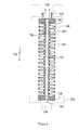
- Figure 7shows another device format formed of a cartridge 110 having an inlet 112 in one end 113 and an outlet 114 in the other end 115 and a series of layers of media 116 in between.
- the NSB removing materialis incorporated into a porous support media such as a nonwoven of PTFE or polyethylene, a cellulosic fibrous pad as in Figure 1 or a porous plastic membrane that contain the NSB removing material either as a filler or as an attached chemistry in the case of the ligands.
- Porous spacers, 118 and 120are adjacent the inlet and outlet respectively and maintain the media in place.
- the mediais formed of a size such that the media contacts the inner wall of the device so that all flow must be through the body of media rather than by passing the media along the inner wall or the like.
- Figure 8shows the use of a stacked filter device 130 as described in WO 01/83077 A1 .
- the device 130can be mounted in a housing 132 which can be disposable capsule or a reusable housing.
- the housing 132has an inlet 134 and an outlet 136.
- a first end cap 138is connected to a second endcap 140 which is in liquid tight communication with the outlet 136. As shown, this is achieved by an O-ring 142 although other means well-known in the art may also be used.
- a central rod 144connects the first endcap 138 to the second endcap 140.
- a series of disks 146 made of the fibrous material containing one or more of the NSB agentsare arranged around the central rod 144.
- each diskhaving a central bore 147 through which the rod 144 extends.
- a series of inner 148 and outer 150 knife edge sealsare alternatively arranged with the disks 146 to create a series of alternating disk pairs. These seals 148 and 150 seal the respective locations of the disks 146 such that all fluid entering the inlet 134 must pass through one or more of the disks 146 before entering the central bore 147 and then to the outlet 136 as shown by arrow 149.
- the rod 144may use a nut or some other means as is well-known in the art to maintain a sealing pressure on the seals 148 and 150 and the disks 146 to ensure that no bypass of liquid occurs.
- Figure 9shows another embodiment in which the NSB agent containing material 152 is formed into a spiral wound assembly 154 as is well-known in the art such as from US 5,490,926 .
- the assembly 154is wound around a permeate collection tube 156 having a series of openings 158 so that fluid passing through the material may enter the tube 156.
- the outer layer 160has a protective outer mesh 162 to hold the filter material 152 in place. This is placed into a housing similar to that of Figure 8 to form a device.
- Figure 10shows another preferred embodiment in which the NSB agent containing material 180 in a tangential flow or TFF device 182.
- the material 180is used on both sides of a central portal or distributor 184. Fluid is brought to the distributor by an inlet 186 and fluid then flows into the distributor and through the material 180 to a collection area 188 and then to an outlet 190.
- Other arrangementscan be made such that the fluid flows from the outside to the center or that only a portion of the fluid passes through the filter layer and the remainder is collected from the distributor and recirculated for a second or subsequent pass through the device. This is particularly useful with fluids that contain a high level of impurities that would otherwise clog the device quickly.
- the tangential flow and recirculationsweeps the filter surfaces clean, reducing the premature clogging of the device.
Landscapes
- Chemical & Material Sciences (AREA)
- Chemical Kinetics & Catalysis (AREA)
- Engineering & Computer Science (AREA)
- Analytical Chemistry (AREA)
- Life Sciences & Earth Sciences (AREA)
- Organic Chemistry (AREA)
- Water Supply & Treatment (AREA)
- Health & Medical Sciences (AREA)
- Molecular Biology (AREA)
- Wood Science & Technology (AREA)
- Textile Engineering (AREA)
- Zoology (AREA)
- Immunology (AREA)
- General Engineering & Computer Science (AREA)
- Inorganic Chemistry (AREA)
- Biochemistry (AREA)
- Bioinformatics & Cheminformatics (AREA)
- General Chemical & Material Sciences (AREA)
- General Health & Medical Sciences (AREA)
- Genetics & Genomics (AREA)
- Geology (AREA)
- Biotechnology (AREA)
- Microbiology (AREA)
- Dispersion Chemistry (AREA)
- Separation Using Semi-Permeable Membranes (AREA)
- Treatment Of Liquids With Adsorbents In General (AREA)
- Peptides Or Proteins (AREA)
- Filtering Materials (AREA)
- Solid-Sorbent Or Filter-Aiding Compositions (AREA)
- Filtration Of Liquid (AREA)
Description
- The present invention relates to a prefilter for purification systems of biological products such as monoclonal antibodies. More particularly it relates to a prefilter for removing non-specific binding (NSB) constituents from a liquid stream before being applied to a purification systems such as an affinity chromatography column.
- In the purification of biological streams, the goal is to capture one or more desired proteins from a liquid stream that contains a variety of components such as other proteins, lipids, aggregated proteins from the cells, media proteins, carbohydrates and colloids from cell walls, DNA, DNA/protein complexes and the like. A number of purification steps may be used but general revolve around one or both of affinity chromatography and ultrafiltration (UF) systems.
- The liquid stream is generally derived from a batch of lysed cells that have been engineered to produce the desired protein. Most of the cell components are removed from the liquid by filtration or centrifugation before chromatography and/or ultrafiltration. However a surprisingly large amount, especially of small or soluble constituents remain in the liquid as it is applied to the purification system. Many of these compete with the desired protein and bind to the affinity material in the column or clog the ultrafilter.
- In affinity chromatography, some of the constituents bind preferentially so over that of the desired protein reducing yields. Others irreversibly bind to the affinity material reducing not only yields but overall capacity especially on subsequent uses of the media.
- Most of these non-desired species are known as non-specific binding species and the problem has been called non-specific binding (NSB).
- Various methods have been attempted to reduce NSB, both to increase yield initially and to maintain capacity over time for a column and to maintain a desired rate of flux and extend the useful life of a UF system.
- Generally, a column is washed several times between the affinity capture stage and the elution stage with various buffers at different pHs and/or with different chemical washes in an attempt to remove the NSB species. Likewise the use of various cleaning regiments have been employed after use to try and remove as much of the NSB species from the media as possible to maintain yield and capacity values.
- None of these have proven to greatly effective especially with the most commonly used affinity media in the biopharmaceutical industry. In part this is due to the affinity ligand itself Protein A. It being a protein is susceptible to denaturing under various conditions that other wise could be used to reduce NSB such as heat, high caustic concentrations and the like.
- UF systems are cleaned after the system has become plugged enough to create too high a back pressure or to reduce the flux below a given level. Its filters are then cleaned with caustic solutions before reuse.
- While the washing with caustic often results in a membrane free of NSB species, it does nothing to extending the life of a filter during filtration. The problem of fouling still exists.
- What is needed is a means for reducing NSB to a lower level before the liquid ever reaches the purification step. The present invention provides such an invention.
- United States patent application
US 2003201229 (Siwak) describes a process for selectively removing plugging constituents from a biomolecule containing solution in a normal flow (NFF) filtration process before viral filtration, such as a process for selectively removing plugging constituents from a biomolecule protein solution in a normal flow (NFF) filtration process and virus particles from the solution in a two-step filtration process. In a first step, a biomolecule solution is filtered through a filtration device containing one or more plugging constituent removing media in the form of one or more layers of adsorptive depth filters, filled microporous membranes or a small bed of media in a normal flow filtration mode of operation, to produce a plugging constituent-free stream. The plugging constituent-free stream can then be filtered through one or more ultrafiltration membranes to retain virus particles at a retention level of at least 3 LRV and to allow passage therethrough of a plugging constituent-free and virus-free biomolecule containing solution. - International patent publication
WO 03066669 - European patent publication
EP 1203774 (Millipore Corp.) describes a process for selectively removing protein aggregates and virus particles from a protein solution in a two-step filtration process. In a first step, a protein solution is filtered by tangential flow filtration through a cellulosic ultrafiltrate membrane at a transmembrane pressure of between about 1 and about 10 psi to produce a first permeate and a retentate stream. Water or aqueous buffer is added to the retentate stream to form an essentially constant volume retentate stream. The first permeate is filtered through a second ultrafiltration membrane to retain virus particles at a retention level of at least 3 LRV and to allow passage therethrough of a protein aggregate free and virus free protein solution. - The present invention is a method according to
claim 1. The prefilter reduces the presence of NSB species that enter the system, thereby extending the yield, capacity and lifetime of the affinity media used in the column. Suitable agents include hydrophobic entities; lipophilic entities; activated carbon; charged cation or anion entities such as ion exchange beads or powders; ligands; and combinations thereof. - The media can be used as is in a column if desired or it can be incorporated into another filter media. Various filter forms such as packed beds, lenticular pads, depth filters, pleated filters and the like can be used.
- A preferred prefilter is in the form of one or more lenticular filtration pad devices, each containing a fibrous media and one or more NSB agents. One such device is a lenticular pad formed of one or more layers of fibrous material containing a NSB agent formed of glass or silica particles embedded in the fibrous material. Another is a lenticular device formed of a series of glass mats. A preferred device is a lenticular pad formed of one or more layers of cellulosic material containing a NSB agent formed of controlled pore glass particles embedded in the fibrous material.
- Another preferred form is as a spiral wound filter cartridge. One or more layers of a fibrous material containing one or more of the NSB agents can be wound around themselves or a central mandrel as is well known in the art.
- Another preferred form is as a disposable capsule containing a series of flat disks of a fibrous material containing one or more NSB agents with the disks having a central bore and a series of inner and outer knife edge seals forming a fluid pathway such that all fluid exiting the device must first now through the disks.
- A further preferred embodiment is in the form of a tangential flow device with fibrous material containing one or more NSB agents arranged in a series of cassettes or pods with the flow running across or tangential to the material and at least a portion of the fluid passing through the material on each pass.
- It is an object of the present invention to provide a prefilter for a protein purification system comprising one or more layers of one or more media selected to remove non-specific binding constituents from a protein containing stream.
- It is an object of the present invention to provide a protein purification system comprising a protein purification system having an inlet and an outlet and a space between wherein the space is filled with media for the purification of proteins and a prefilter upstream of and connected to the inlet of the system, said prefilter comprising one or more layers of one or more media selected to remove non-specific binding constituents from a protein containing stream.
- It is an object of the present invention to provide a protein purification system comprising a protein purification system having an inlet and an outlet and a space between wherein the space is filled with media for the purification of proteins and a prefilter upstream of and connected to the inlet of the system, said prefilter comprising one or more layers of one or more media selected to remove non-specific binding constituents from a protein containing stream and a storage tank in fluid communication with the outlet of the prefilter and the inlet of the purification system.
- It is an object of the present invention to provide a prefilter system for an affinity chromatography column comprising one or more prefilters in the form of one or more lenticular pad devices, each device having a central lenticular support structure, one or more prefilter pads, each pad being formed of one or more layers of one or more media selected to remove non-specific binding constituents from a protein containing stream, an edge seal securing the one or more pads to the support and a central outlet such that all fluid entering the device must pass through the one or more prefilter pads and the support before reaching the central outlet and a housing in which the one or more prefilters are arranged, the housing having a central rod on to which each device is mounted by its central outlet the central rod being connected to an outlet of the housing, a space between the devices and the inner wall of the housing for fluid flow and an inlet in the housing.
- It is another object to provide a prefilter for an affinity chromatography column comprising one or more layers of one or more media selected to remove non-specific binding constituents from a protein containing stream wherein the prefilter is in the form of one or more lenticular pad devices, each device having a central lenticular support structure, one or more prefilter pads, an edge seal securing the pads to the support and a central outlet such that all fluid entering the device must pass through the one or more prefilter pads and the support before reaching the central outlet.
Figure 1A shows a first embodiment of the present invention in cross-sectional view.Figure 1B shows a second embodiment of the present invention in cross-sectional view.Figure 2 shows a prefilter of one embodiment of the present invention in cross-sectional view.Figure 3 shows a prefilter of one embodiment of the present invention in cross-sectional view.Figure 4 shows a prefilter of one embodiment of the present invention in cross-sectional view.Figure 5 shows a prefilter of one embodiment of the present invention in cross-sectional view.Figure 6 shows a prefilter of one embodiment of the present invention in cross-sectional view.Figure 7 shows a prefilter of one embodiment of the present invention in cross-sectional view.Figure 8 shows a prefilter of one embodiment of the present invention in cross-sectional view.Figure 9 shows a prefilter of one embodiment of the present invention in cross-sectional view.Figure 10 shows a prefilter of one embodiment of the present invention in cross-sectional view.- The present invention is a prefilter used upstream of a protein purification system such as an affinity media containing chromatography column to remove some or all of the NSB species before they reach the purification system. In this way, the amount of NSB is reduced and media has higher yields and capacity and a longer life than is achieved today.
- The prefilter contains one or more types of materials that are capable of removing the NSB species from the liquid. In this way, the amount of NSB species reaching the column is reduced or eliminated, making their competition for binding sites less or non-existent. This leads to several advantages and benefits. For chromatography systems, one achieves higher overall capacity for the desired species that are to be captured, higher yields of the desired species as more of that species will have binding sites available for it to be captured upon with the reduced load of NSB. species and greater retained capacity over time as less irreversible binding of NSB species will occur allowing the chromatography media to be cleaned and reused to a greater degree than is possible today.
- The NSB removing material used in the prefilter can be any material shown to remove the NSB specie or species that are desired to be removed from the liquid stream before chromatographic separation. Typically, these materials are selected from the group consisting of hydrophobic entities, lipophilic entities, activated carbon, charged cation or anion entities such as ion exchange beads, ligands or derivitized version of each, and combinations thereof.
- These materials may be incorporated into a media, preferably a porous media that can then be incorporated into a selected device design. Such media can be in the form of films, porous films, membranes, porous mats, porous monoliths, nonwovens, woven fabrics and the like.
- They can be formed of a wide variety of materials as are used by one of ordinary skill in the art of filtration such as polyolefins including polyethylene and polypropylene, polyvinyl alcohols, polyvinyl chlorides, polysulfones, polyarylsulfones, polyethersulfones, polyphenylsulphones, PTFE, PFA resins, polyesters, nylons, polyamides, polyimides, PVDF, celluloses and modified cellulosic materials such as cellulose acetate, ceramics, glass such as borosilicate glass or controlled pore glass and the like.
- The form of the NSB removing material will dictate whether and if so how it is incorporated into the selected media. For example, ligands can be attached by surface chemistry to a substrate such as controlled pore glass. Activated carbon, silica, controlled pore glass and the like can be in the form of particles such as beads and added as a filler to the media as it is being formed. One example is to add the NSB removing material as a filler to PTFE resin and compound the two together to obtain a porous membrane of PTFE containing the filler of NSB removing material dispersed throughout the fibrous PTFE structure. Some materials, such as beads of activated carbon, silica, controlled pore glass are self supportive and do not need to be incorporated into a media. Instead they can be used as is in a bed of such material. However they can easily be incorporated into a media as a filler if desired.
- A prefilter according to the present invention can be formed of a variety of materials and in a variety of device designs.
Figure 1A shows a first embodiment of the present invention. A chromatography column 2 has aninlet 4 and anoutlet 6 and a space 8 in between theinlet 4 andoutlet 6. The space 8 is filled with one or more types of affinity media 10 such as Protein A or Protein G ligands, or chemical ligands such as 2-aminobenzimidazole (ABI), aminomethylbenzimidazole (AMBI), mercaptoethylpyridine (MEP) or mercaptobenzimidazole (MBI) attached to a chromatographic bead such as agarose, silica or controlled pore glass. Such affinity media are well known in the art and can be obtained for example from Millipore Corporation under the tradename ProSep®A media (Protein A based ligand on controlled pore glass) or ProSep®G media (Protein G based ligand on controlled pore glass).- A prefilter assembly 12 is located upstream of the column 2 such that the
outlet 14 of the prefilter assembly 12 is in fluid communication with theinlet 4 of the column 2. The assembly 12 is comprised of ahousing 16 having theoutlet 14 and an inlet 18, acentral rod assembly 20 connected to theoutlet 14 and a series ofprefilters 22 arranged about therod 20 in a liquid tight fashion to therod 20, each other 22 and within themselves 22 so that all fluid exiting theoutlet 14 had to first enter the inlet 18, pass through one of theprefilters 22 to therod 20 and then to theoutlet 14. Figure 1B shows an alternative embodiment ofFigure 1A in which anintermediate storage tank 3 is positioned between the prefilter 12 and the column 2. The tank can be used to store the treated fluid before it goes onto the column so that the either the prefilter or the column or both can be run in a batch mode rather than in a continuous mode if desired.- Other additional elements may be added to the embodiments of
Figures 1A-1B such as one or more pumps, valves, pressure gauges, temperature sensors or controls, sampling ports, and the like as are commonly used in the biopharmaceutical industry. - The
prefilters 22 ofFigure 1A-B are shown in more detail inFigure 2 are made as supported cells with the one or more layers of porous media, in this case twolayers 24A and B being attached to the outer surfaces of a central support device 26. The supported cells are formed on a lenticular (double convex) support structure formed of a series of radially extending convex shaped ribs (not shown) which are held to each other by a series of spaced rings (Not shown) at various circumferences from the center of the radial ribs. SeeUS 4,704,207 and4,783,262 . The spaces between the ribs form the channels through which fluid that has flowed through the filter media is collected and sent to thecore 28 for further use. The rings are arranged in a manner so that the fluid flow is only minimally hindered. Typically, adjacent rings are formed on opposite sides of the ribs so that flow is over one ring and then under the other. The outer edge of the media is liquid tightly secured by anouter sealing edge 30. - The prefilters may be used singularly or in groups. See
US 2,788,901 and5,085,784 . Typically the prefilters are used in groups (generally of 16 to 20 per group) stacked upon a central rod within a housing as shown inFigure 1 . Fluid to be filtered enters the bottom or side adjacent the bottom of the housing and flows through the filter media to the lenticular support structure that direct the fluid to the core where it is collected and removed from the housing through an outlet in the bottom or side of the housing. - In a preferred embodiment of this design, the filter includes multiple layers of media. Such multiple layers may also be different materials and/or different pore sizes. Preferably, each such media has different pore size ranges, so a great variety of different cartridges can be made from the present invention. These media can be obtained from a variety of sources such as MILLISTAK+ ™ media available from Millipore Corporation of Bedford, Massachusetts. Filter Materials of Waupaca, Wisconsin also produces a wide array of media suitable for the device of the present invention.
- Representative media useful for forming the filter include the fiber of polyolefins such as polyethylene, polypropylene, cellulose including cellulose/silica blends as well as cellulose derivatives such as cellulose acetate, cotton, polyamides, polyesters, fiberglass, polytetrafluoroethylene (PTFE), fluoropolymers such as PFA, MFA and FEP or the like. Celluosic media or cellulosic composite media are preferred such as the MILLISTAK+™ filters available from Millipore Corporation of Billerica, Massachusetts. These materials and their methods of making them either by a wet process (similar to papermaking) or a dry process are well known in the art,See
US 5,928,588 and4,007,113 and4,007,114 for examples of making such media. Similar materials are appropriate for the structural portions of the cartridge. Preferably, they are made of polypropylene. Other materials suitable for use in these applications can include but are not limited to thermoplastics such as other polyolefins such as polyethylenes including ultrahigh molecular weight polyethylenes, copolymers or terpolymers of polyolefins; nylons; PTFE resin, PFA, PVDF, ECTFE, and other fluorinated resins, particularly perfluorinated thermoplastic resins; polycarbonates; metallocene derived polymers, polysulphones; modified polysulphones such as polyethersulphone, polyarylsulphones or polyphenylsulphones; any glass or other reinforced plastic; or a metal such as stainless steel, aluminum, copper, bronze, brass, nickel, chromium or titanium or alloys or blends thereof. - In a second embodiment of the present invention, one uses a column of packed NSB removing material. Such a device is shown in
Figure 3 . In this embodiment, a column 40 has atop cover 42 and abottom cover 44, thetop cover 42 having aninlet 46 and thebottom cover 44 having an outlet 48. Both theinlet 46 and outlet 48 are separated from thebody 50 of the column 40 by one or more porous devices such as frits, membranes, screens, distributors and the like that control the distribution of the fluid into and out of the column 40 and also prevent movement of theNSB removing materials 52 out of the column 40. Such devices are well known and can be formed of sintered plastics such as sintered polyethylene, sintered metals such as sintered stainless steel or nickel, a glass mat or mesh, a plastic mat, netting or mesh such as a polyethylene nonwoven mat and the like. - In this embodiment, the
NSB removing materials 52 are shown as particles. They can be in the form of regular beads, irregular particles, shards, fibers, monoliths or any other form in which they are normally supplied. Such particle-based materials include but are not limited to silica, silicates, controlled pore glass, and derivitized versions of any of the above as well as activated carbon beads. The column may contain a single type of NSB removing material or if desired it may contain either a blend of different NSB removing materials or a series of different NSB removing materials in individual layers within the column. The particles can be of any size normally used in bead based filtration, but typically are from about 10 to about 1000 microns in average diameter. To ensure even flow with low back pressure, it is preferred that the particles are of substantially the same size, generally about 50% or more of the particles are +/- 10% the average diameter. In some instances they can be monodispersed particles, at least 90% are +/- 10% the average diameter. - The NSB removing material may also be incorporated into a filter cartridge device as in
Figure 4 either as a pleated filter or as a depth filter. In this embodiment, the NSB removing material is incorporated into a porous support media such as a nonwoven of PTFE or polyethylene, a cellulosic fibrous pad as inFigure 1 or a porous plastic membrane, each of which contain the NSB removing material either as a filler or as an attached chemistry as in the case of the ligands. Acartridge 51 contains a central core 55 that is connected to afirst endcap 54 which forms anoutlet 56 from thecartridge 51. The NSB removingmaterial containing media 57 is upstream from the core 55. If desired a support layer or cage (not shown) may be used either on the outside or inside or both sides of themedia 57 as is well known in the art. Themedia 57 is liquid tightly sealed to thefirst endcap 54 and asecond endcap 60 at its respective ends so that all fluid entering thecartridge 51 throughinlet 53 must flow through themedia 57 before entering the core 55. Anouter sleeve 58 surrounds themedia 57 and is also sealed to theendcap 54 such as by mated threads, clamps, adhesives, solvent bonding, ultrasonic welding and the like. In the pleated form, one or more layers of media may be used. Likewise in the depth filter form the media maybe one thick layer, such as a mat or a felt or a monolith or it may be a single sheet of media that has been rolled up upon itself or it may be series of individual sheets on top of each other and sealed along their open two edges (not shown). The cartridge may go into a reusable housing that is liquid tight or it may have the outer sleeve liquid tight (as shown) so that the cartridge is in the form of a disposable capsule cartridge. Figure 5 shows another device embodiment. In this embodiment as well, the NSB removing material is incorporated into a porous support media such as a nonwoven of PTFE or polyethylene, a cellulosic fibrous pad as inFigure 1 or a porous plastic membrane that contain the NSB removing material either as a filler or as an attached chemistry in the case of the ligands. This design is also shown inUS 4,895,806 and consist of two halves, 70 and 72, thefirst half 70 having an inlet 74and thesecond half 72 having anoutlet 76. Inside the device are a plurality ofmedia discs 78 stacked one on top of the other between a top and bottomporous substrate gaskets 84.Figure 6 shows a variation on the design ofFigure 5 in which a series ofmedia layers 90 are separated from each other byspacers 92 and are all liquid tightly sealed around the top and bottom circumferences of series ofmedia layers 90 to the interior of the device bygaskets 94. The device is formed of twohalves inlet 102 and outlet 104 formed in respective ends of the twohalves Figure 7 shows another device format formed of acartridge 110 having aninlet 112 in oneend 113 and anoutlet 114 in theother end 115 and a series of layers ofmedia 116 in between. Again the NSB removing material is incorporated into a porous support media such as a nonwoven of PTFE or polyethylene, a cellulosic fibrous pad as inFigure 1 or a porous plastic membrane that contain the NSB removing material either as a filler or as an attached chemistry in the case of the ligands. Porous spacers, 118 and 120 are adjacent the inlet and outlet respectively and maintain the media in place. The media is formed of a size such that the media contacts the inner wall of the device so that all flow must be through the body of media rather than by passing the media along the inner wall or the like.- Other device designs can and are possible with the present invention.
- For example,
Figure 8 shows the use of astacked filter device 130 as described inWO 01/83077 A1 device 130 can be mounted in ahousing 132 which can be disposable capsule or a reusable housing. Thehousing 132 has aninlet 134 and anoutlet 136. Afirst end cap 138 is connected to asecond endcap 140 which is in liquid tight communication with theoutlet 136. As shown, this is achieved by an O-ring 142 although other means well-known in the art may also be used. Acentral rod 144 connects thefirst endcap 138 to thesecond endcap 140. A series ofdisks 146 made of the fibrous material containing one or more of the NSB agents are arranged around thecentral rod 144. This is achieved by each disk having acentral bore 147 through which therod 144 extends. A series of inner 148 and outer 150 knife edge seals are alternatively arranged with thedisks 146 to create a series of alternating disk pairs. Theseseals disks 146 such that all fluid entering theinlet 134 must pass through one or more of thedisks 146 before entering thecentral bore 147 and then to theoutlet 136 as shown byarrow 149. Therod 144 may use a nut or some other means as is well-known in the art to maintain a sealing pressure on theseals disks 146 to ensure that no bypass of liquid occurs. Figure 9 shows another embodiment in which the NSBagent containing material 152 is formed into aspiral wound assembly 154 as is well-known in the art such as fromUS 5,490,926 . Theassembly 154 is wound around apermeate collection tube 156 having a series ofopenings 158 so that fluid passing through the material may enter thetube 156. Theouter layer 160 has a protectiveouter mesh 162 to hold thefilter material 152 in place. This is placed into a housing similar to that ofFigure 8 to form a device.Figure 10 shows another preferred embodiment in which the NSBagent containing material 180 in a tangential flow orTFF device 182. Thematerial 180 is used on both sides of a central portal ordistributor 184. Fluid is brought to the distributor by aninlet 186 and fluid then flows into the distributor and through the material 180 to acollection area 188 and then to anoutlet 190. Other arrangements can be made such that the fluid flows from the outside to the center or that only a portion of the fluid passes through the filter layer and the remainder is collected from the distributor and recirculated for a second or subsequent pass through the device. This is particularly useful with fluids that contain a high level of impurities that would otherwise clog the device quickly. The tangential flow and recirculation sweeps the filter surfaces clean, reducing the premature clogging of the device.- Other embodiments can be used as well and would be obvious to one of ordinary skill in the art and are meant to be encompassed in the present invention.
Claims (7)
- A method of removing non-specific binding constituents from a protein containing stream comprising:flowing the protein containing stream through a protein purification system comprising a prefilter, the prefilter comprising one or more layers of one or more media selected to remove non-specific binding constituents from the protein containing stream, wherein the prefilter is upstream of and in fluid communication with an affinity chromatography column,further wherein the media is comprised of a material selected from the group consisting of hydrophobic entities, lipophilic entities, activated carbon, charged cation or anion entities, ligands and derivitized version of each, and combinations thereof.
- The method according to claim 1, wherein the prefilter has an inlet and an outlet and a space between, wherein the space is filled with media containing one or more agents for removing non-specific binding, and optionally wherein the media is in the form of a bead.
- The method according to claim 1, wherein the prefilter is in the form of one or more lenticular pad devices, each device having a central lenticular support structure, one or more prefilter pads, an edge seal securing the pads to the support and a central outlet such that all fluid entering the device must pass through the one or more prefilter pads and the support before reaching the central outlet.
- The method according to claim 1, wherein one or more prefilters are in the form of one or more lenticular pad devices, each device having a central lenticular support structure, one or more prefilter pads, each pad being formed of one or more layers of one or more media selected to remove non-specific binding constituents from a protein containing stream, an edge seal securing the one or more pads to the support and a central outlet such that all fluid entering the device must pass through the one or more prefilter pads and the support before reaching the central outlet and a housing in which the one or more prefilters are arranged, the housing having a central rod on to which each device is mounted by its central outlet the central rod being connected to an outlet of the housing, a space between the devices and the inner wall of the housing for fluid flow and an inlet in the housing.
- The method according to claim 1, wherein the media is formed by embedding the selected material in a fibrous filter pad or membrane.
- The method according to claim 1, further comprising an intermediate storage tank placed between an outlet of the prefilter and an inlet to the affinity chromatography column and is in fluid communication with both.
- The method according to claim 1, wherein the prefilter is in the form ofa) a spiral wound filter cartridge, orb) a disposable capsule containing a series of flat disks of a fibrous material containing one or more NSB agents with the disks having a central bore and a series of inner and outer knife edge seals forming a fluid pathway such that all fluid exiting the device must first flow through the disks.
Applications Claiming Priority (4)
| Application Number | Priority Date | Filing Date | Title |
|---|---|---|---|
| US55476904P | 2004-03-19 | 2004-03-19 | |
| US554769P | 2004-03-19 | ||
| US65050405P | 2005-02-07 | 2005-02-07 | |
| US650504P | 2005-02-07 |
Publications (2)
| Publication Number | Publication Date |
|---|---|
| EP1577319A1 EP1577319A1 (en) | 2005-09-21 |
| EP1577319B1true EP1577319B1 (en) | 2019-11-27 |
Family
ID=34841245
Family Applications (1)
| Application Number | Title | Priority Date | Filing Date |
|---|---|---|---|
| EP05251124.3AExpired - LifetimeEP1577319B1 (en) | 2004-03-19 | 2005-02-25 | Protein purification with prefiltering |
Country Status (5)
| Country | Link |
|---|---|
| US (3) | US7390403B2 (en) |
| EP (1) | EP1577319B1 (en) |
| JP (4) | JP5089022B2 (en) |
| DK (1) | DK1577319T3 (en) |
| ES (1) | ES2764441T3 (en) |
Families Citing this family (37)
| Publication number | Priority date | Publication date | Assignee | Title |
|---|---|---|---|---|
| JPH0790948B2 (en) | 1988-11-07 | 1995-10-04 | シャープ株式会社 | Double-feed detection device in sheet circulating supply device |
| US7722832B2 (en) | 2003-03-25 | 2010-05-25 | Crystaphase International, Inc. | Separation method and assembly for process streams in component separation units |
| US7390403B2 (en)* | 2004-03-19 | 2008-06-24 | Millipore Corporation | Prefilter system for biological systems |
| US20070005006A1 (en)* | 2005-06-15 | 2007-01-04 | Rosenfeld Paul E | Methods and devices for removal of toxic compounds from breast milk |
| US7510654B2 (en) | 2005-12-29 | 2009-03-31 | Spf Innovations, Llc | Method and apparatus for the filtration of biological samples |
| EP1862207A1 (en)* | 2006-05-31 | 2007-12-05 | NV Bekaert SA | Disc-shaped filter elements and methods to provide disc-shaped filter elements |
| EP2160226B1 (en) | 2007-06-27 | 2015-11-11 | GE Healthcare Bio-Sciences Corp. | System and method for assembling a large scale chromatograpy structure |
| US8231787B2 (en)* | 2008-05-06 | 2012-07-31 | Spf Innovations, Llc | Tangential flow filtration system |
| US20090321338A1 (en)* | 2008-06-25 | 2009-12-31 | Millipore Corporation | Chromatography apparatus |
| EP4559926A3 (en) | 2009-08-06 | 2025-08-06 | F. Hoffmann-La Roche AG | Virus filtration methods |
| EP2525891B1 (en) | 2010-01-22 | 2020-10-07 | Donaldson Company, Inc. | Pulse jet air cleaner systems; evacution valve arrangements; air cleaner components; and, methods |
| EP2732021B1 (en) | 2011-07-08 | 2020-05-27 | EMD Millipore Corporation | Improved depth filters for disposable biotechnological processes |
| US9096648B2 (en)* | 2011-08-19 | 2015-08-04 | Emd Millipore Corporation | Methods of reducing level of one or more impurities in a sample during protein purification |
| EP2682168A1 (en)* | 2012-07-02 | 2014-01-08 | Millipore Corporation | Purification of biological molecules |
| US9650411B2 (en)* | 2012-08-07 | 2017-05-16 | Kyowa Hakko Kirin Co., Ltd. | Method of purifying protein |
| SG11201404681VA (en) | 2012-09-17 | 2014-09-26 | Grace W R & Co | Chromatography media and devices |
| BR112015015800A2 (en) | 2013-01-14 | 2017-07-11 | Cummins Filtration Ip Inc | cleanable filter and methods for cleaning filter element and system installed filter |
| CN104955834A (en) | 2013-02-26 | 2015-09-30 | Emd密理博公司 | Selective removal of proteins from protein mixtures by adjusting solution conditions using activated carbon |
| AU2014275018A1 (en)* | 2013-06-06 | 2015-12-24 | Gusmer Enterprises Inc. | Dry formed filters and methods of making the same |
| WO2015005961A1 (en) | 2013-07-12 | 2015-01-15 | Emd Millipore Corporation | A method of determining virus removal from a sample containing a target protein using activated carbon |
| EP3019262A1 (en) | 2013-07-12 | 2016-05-18 | Merck Patent GmbH | Removal of fragments from a sample containing a target protein using activated carbon |
| US11389783B2 (en) | 2014-05-02 | 2022-07-19 | W.R. Grace & Co.-Conn. | Functionalized support material and methods of making and using functionalized support material |
| US10384156B2 (en)* | 2014-09-12 | 2019-08-20 | Hollingsworth & Vose Company | Filter media comprising fibers including charged particles |
| EP3302784B1 (en) | 2015-06-05 | 2021-10-06 | W.R. Grace & Co.-Conn. | Adsorbent bioprocessing clarification agents and methods of making and using the same |
| EP3393266B1 (en) | 2015-12-22 | 2024-05-01 | FILTROX North America, Inc. | Multilayer filtration device |
| US10744426B2 (en) | 2015-12-31 | 2020-08-18 | Crystaphase Products, Inc. | Structured elements and methods of use |
| US10054140B2 (en) | 2016-02-12 | 2018-08-21 | Crystaphase Products, Inc. | Use of treating elements to facilitate flow in vessels |
| US11214789B2 (en) | 2016-05-03 | 2022-01-04 | Flodesign Sonics, Inc. | Concentration and washing of particles with acoustics |
| US10668411B2 (en)* | 2016-07-20 | 2020-06-02 | Entegris, Inc. | Depth filtration media with multiple organic and/or inorganic materials |
| WO2020209267A1 (en) | 2019-04-08 | 2020-10-15 | 旭化成メディカル株式会社 | Polyamide medium for purifying protein-containing solution and method for producing said polyamide medium |
| EP4076719A1 (en) | 2019-12-20 | 2022-10-26 | Crystaphase Products Inc. | Resaturation of gas into a liquid feedstream |
| WO2021229341A1 (en) | 2020-05-12 | 2021-11-18 | 3M Innovative Properties Company | Spacer ring for chromatography device |
| EP4210865A1 (en) | 2020-09-09 | 2023-07-19 | Crystaphase Products Inc. | Process vessel entry zones |
| JPWO2022107876A1 (en)* | 2020-11-20 | 2022-05-27 | ||
| US12220657B2 (en)* | 2021-04-30 | 2025-02-11 | Pall Corporation | Filter disk segments |
| DE102022130328A1 (en)* | 2022-11-16 | 2024-05-16 | Erbslöh Geisenheim GmbH | Filter cloth and filter cloth assembly for the treatment of liquids |
| CN118179116B (en)* | 2024-05-17 | 2024-07-30 | 山东优倍克生物科技有限公司 | Separation and purification process and device for animal protein peptide |
Citations (1)
| Publication number | Priority date | Publication date | Assignee | Title |
|---|---|---|---|---|
| WO2004103530A1 (en)* | 2003-05-19 | 2004-12-02 | Millipore Corporation | Process for prefiltration of a protein solution |
Family Cites Families (45)
| Publication number | Priority date | Publication date | Assignee | Title |
|---|---|---|---|---|
| NL19860C (en)* | 1952-09-23 | |||
| US2788901A (en)* | 1954-10-11 | 1957-04-16 | American Felt Co | Fused edge filter unit |
| US3241678A (en)* | 1961-12-13 | 1966-03-22 | American Felt Co | Fibrous structures |
| FR1541107A (en) | 1967-08-24 | 1968-10-04 | filter elements and filters fitted with such elements | |
| GB1279856A (en) | 1968-08-23 | 1972-06-28 | Gen Electric | Improvements in starting control scheme for rectifier-inverter systems |
| US3647084A (en)* | 1969-10-17 | 1972-03-07 | William W Nugent & Co Inc | Filter |
| CA1044537A (en)* | 1973-05-09 | 1978-12-19 | Amf Incorporated | Filter medium and process |
| JPS5092558A (en) | 1973-12-21 | 1975-07-24 | ||
| US3976576A (en)* | 1974-04-01 | 1976-08-24 | The University Of Utah | Dialyzer cartridge |
| US4016081A (en)* | 1974-04-22 | 1977-04-05 | Baxter Laboratories, Inc. | Staged membrane diffusion device and membrane support |
| GB2003053B (en)* | 1977-08-19 | 1982-07-14 | Kuraray Co | Plate type fluid treatment apparatus |
| SE7801230L (en) | 1978-02-02 | 1979-08-03 | Gambro Ab | DEVICE FOR DIFFUSION OF THE SUBJECT BETWEEN TWO FLUIDS WHILE AT THE SAME TEMPERATURE OF ATMINSTONE ONE OF THESE FLUIDES |
| US4228015A (en)* | 1979-01-29 | 1980-10-14 | Baxter Travenol Laboratories, Inc. | Plasma treatment apparatus |
| CA1148094A (en) | 1979-11-05 | 1983-06-14 | Wayne S. Merrill | Filter cartridges and methods and components for making them |
| US5059654A (en)* | 1983-02-14 | 1991-10-22 | Cuno Inc. | Affinity matrices of modified polysaccharide supports |
| US4704207A (en) | 1985-12-02 | 1987-11-03 | Cuno Incorporated | Filter cartridge including external cell separators |
| GB2201904B (en)* | 1987-02-14 | 1990-12-19 | Domnick Hunter Filters Ltd | Device for liquid chromatography or immobilised enzyme reaction |
| US4783262A (en)* | 1987-03-30 | 1988-11-08 | Cuno Incorporated | Separator for cell type filter element |
| DE3900934A1 (en)* | 1989-01-14 | 1990-07-19 | Seitz Enzinger Noll Masch | FILTER DEVICE |
| US4981591A (en) | 1989-04-07 | 1991-01-01 | Cuno, Incorporated | Cationic charge modified filter media |
| US5085784A (en)* | 1989-04-07 | 1992-02-04 | Cuno, Incorporated | Use of cationic charge modified filter media |
| GB9106481D0 (en)* | 1991-03-27 | 1991-05-15 | Pall Corp | Filters and filter units |
| JP3439503B2 (en) | 1993-06-28 | 2003-08-25 | 旭化成株式会社 | Protein separation and purification method |
| SE503277C2 (en)* | 1993-07-20 | 1996-05-13 | Alfa Laval Brewery Syst Ab | Filters intended for cross-flow filtration |
| EP0713420B1 (en)* | 1993-08-13 | 1997-08-06 | Minnesota Mining And Manufacturing Company | Cartridge filter with insoluble enzyme particulates contained thereon |
| US5468847A (en) | 1994-03-10 | 1995-11-21 | Minnesota Mining And Manufacturing Company | Method of isolating and purifying a biomacromolecule |
| US5490926A (en)* | 1994-10-31 | 1996-02-13 | W.R. Grace & Co.-Conn. | Spiral-wound filtration cartridge with longitudinal bypass feature |
| US5824217A (en)* | 1996-03-27 | 1998-10-20 | Millipore Corporation | Membrane filtration apparatus |
| US6478969B2 (en)* | 1996-09-06 | 2002-11-12 | Pall Corporation | Shear separation method and system |
| US5882517A (en)* | 1996-09-10 | 1999-03-16 | Cuno Incorporated | Porous structures |
| US5766472A (en)* | 1996-10-29 | 1998-06-16 | Illinois Tool Works Inc. | Method and apparatus for a filter assembly |
| US5965019A (en)* | 1996-11-26 | 1999-10-12 | Cuno Incorporated | Encapsulated lenticular filter cartridge |
| US5853445A (en)* | 1997-08-06 | 1998-12-29 | Dana Corporation | Interlocking dual filter |
| WO1999007458A1 (en) | 1997-08-06 | 1999-02-18 | Genentech, Inc. | Hollow fiber co-flow filtration device |
| DE19837257A1 (en)* | 1998-08-17 | 2000-02-24 | Seitz Filter Werke | Stacked filter module comprises inter-layered filter medium, drainage spacers, seals and passage sections |
| EP1286741A1 (en) | 2000-04-28 | 2003-03-05 | Millipore Corporation | Filter cartridges and methods of manufacturing same |
| JP2002114799A (en)* | 2000-08-01 | 2002-04-16 | Nihon Pharmaceutical Co Ltd | Method for removing virus |
| US6365395B1 (en) | 2000-11-03 | 2002-04-02 | Millipore Corporation | Process for removing protein aggregates and virus from a protein solution |
| WO2003040166A2 (en) | 2001-11-02 | 2003-05-15 | Millipore Corporation | Membrane adsorber device |
| US20030201229A1 (en) | 2002-02-04 | 2003-10-30 | Martin Siwak | Process for prefiltration of a protein solution |
| WO2003066669A2 (en) | 2002-02-04 | 2003-08-14 | Millipore Corporation | Process for removing protein aggregates and virus from a protein solution |
| DE10217262A1 (en) | 2002-04-18 | 2003-11-06 | Pall Corp | Filter module and method for producing a filled filter module |
| DE602004013731D1 (en)* | 2003-03-05 | 2008-06-26 | Hydranautics | DIPLOCKABLE MEMBRANE MODULE WITH REPLACEABLE MEMBRANE ELEMENTS |
| DE10331383A1 (en) | 2003-07-11 | 2005-02-10 | E. Begerow Gmbh & Co | Device for filtering fluids |
| US7390403B2 (en)* | 2004-03-19 | 2008-06-24 | Millipore Corporation | Prefilter system for biological systems |
- 2005
- 2005-02-23USUS11/063,477patent/US7390403B2/enactiveActive
- 2005-02-25ESES05251124Tpatent/ES2764441T3/ennot_activeExpired - Lifetime
- 2005-02-25DKDK05251124.3Tpatent/DK1577319T3/enactive
- 2005-02-25EPEP05251124.3Apatent/EP1577319B1/ennot_activeExpired - Lifetime
- 2005-03-16JPJP2005074413Apatent/JP5089022B2/ennot_activeExpired - Fee Related
- 2008
- 2008-03-13USUS12/075,736patent/US9072988B2/ennot_activeExpired - Fee Related
- 2009
- 2009-04-24JPJP2009106004Apatent/JP2009173675A/enactivePending
- 2012
- 2012-03-12JPJP2012054079Apatent/JP2012111781A/ennot_activeWithdrawn
- 2015
- 2015-05-01JPJP2015093881Apatent/JP6212511B2/ennot_activeExpired - Fee Related
- 2015-06-02USUS14/728,496patent/US20150258468A1/ennot_activeAbandoned
Patent Citations (1)
| Publication number | Priority date | Publication date | Assignee | Title |
|---|---|---|---|---|
| WO2004103530A1 (en)* | 2003-05-19 | 2004-12-02 | Millipore Corporation | Process for prefiltration of a protein solution |
Also Published As
| Publication number | Publication date |
|---|---|
| DK1577319T3 (en) | 2020-01-20 |
| JP2009173675A (en) | 2009-08-06 |
| JP5089022B2 (en) | 2012-12-05 |
| JP2015147799A (en) | 2015-08-20 |
| JP2005263803A (en) | 2005-09-29 |
| EP1577319A1 (en) | 2005-09-21 |
| ES2764441T3 (en) | 2020-06-03 |
| US20080164195A1 (en) | 2008-07-10 |
| US20050205489A1 (en) | 2005-09-22 |
| JP2012111781A (en) | 2012-06-14 |
| US20150258468A1 (en) | 2015-09-17 |
| US9072988B2 (en) | 2015-07-07 |
| US7390403B2 (en) | 2008-06-24 |
| JP6212511B2 (en) | 2017-10-11 |
Similar Documents
| Publication | Publication Date | Title |
|---|---|---|
| EP1577319B1 (en) | Protein purification with prefiltering | |
| US11884701B2 (en) | Chromatography membranes, devices containing them, and methods of use thereof | |
| US4675104A (en) | Chromatography column | |
| US4743373A (en) | Chromatography column | |
| US4986909A (en) | Chromatography column | |
| JP2008516753A (en) | Pleated multilayer filter media and cartridge | |
| US7404493B2 (en) | Filter device including pleated filter incorporated in a housing | |
| US7261817B2 (en) | Filter module and device for static filtration of fluids with such a module | |
| JP2000517240A (en) | Filtration unit with pleated filter element | |
| AU3480500A (en) | Graded particle-size retention filter medium for cell-type filter unit | |
| WO2004103530A1 (en) | Process for prefiltration of a protein solution |
Legal Events
| Date | Code | Title | Description |
|---|---|---|---|
| PUAI | Public reference made under article 153(3) epc to a published international application that has entered the european phase | Free format text:ORIGINAL CODE: 0009012 | |
| AK | Designated contracting states | Kind code of ref document:A1 Designated state(s):AT BE BG CH CY CZ DE DK EE ES FI FR GB GR HU IE IS IT LI LT LU MC NL PL PT RO SE SI SK TR | |
| AX | Request for extension of the european patent | Extension state:AL BA HR LV MK YU | |
| 17P | Request for examination filed | Effective date:20050811 | |
| AKX | Designation fees paid | Designated state(s):AT BE BG CH CY CZ DE DK EE ES FI FR GB GR HU IE IS IT LI LT LU MC NL PL PT RO SE SI SK TR | |
| 17Q | First examination report despatched | Effective date:20080909 | |
| RAP1 | Party data changed (applicant data changed or rights of an application transferred) | Owner name:EMD MILLIPORE CORPORATION | |
| STAA | Information on the status of an ep patent application or granted ep patent | Free format text:STATUS: EXAMINATION IS IN PROGRESS | |
| RAP1 | Party data changed (applicant data changed or rights of an application transferred) | Owner name:EMD MILLIPORE CORPORATION | |
| RIC1 | Information provided on ipc code assigned before grant | Ipc:B01D 29/11 20060101ALI20050707BHEP Ipc:B01D 29/21 20060101ALI20050707BHEP Ipc:B01D 29/01 20060101ALI20050707BHEP Ipc:B01D 29/41 20060101ALI20050707BHEP Ipc:C07K 1/34 20060101AFI20050707BHEP Ipc:B01D 15/08 20060101ALI20050707BHEP | |
| GRAP | Despatch of communication of intention to grant a patent | Free format text:ORIGINAL CODE: EPIDOSNIGR1 | |
| STAA | Information on the status of an ep patent application or granted ep patent | Free format text:STATUS: GRANT OF PATENT IS INTENDED | |
| INTG | Intention to grant announced | Effective date:20190621 | |
| RIN1 | Information on inventor provided before grant (corrected) | Inventor name:SIWAK, MARTIN | |
| GRAS | Grant fee paid | Free format text:ORIGINAL CODE: EPIDOSNIGR3 | |
| GRAA | (expected) grant | Free format text:ORIGINAL CODE: 0009210 | |
| STAA | Information on the status of an ep patent application or granted ep patent | Free format text:STATUS: THE PATENT HAS BEEN GRANTED | |
| AK | Designated contracting states | Kind code of ref document:B1 Designated state(s):AT BE BG CH CY CZ DE DK EE ES FI FR GB GR HU IE IS IT LI LT LU MC NL PL PT RO SE SI SK TR | |
| REG | Reference to a national code | Ref country code:GB Ref legal event code:FG4D | |
| REG | Reference to a national code | Ref country code:CH Ref legal event code:EP | |
| REG | Reference to a national code | Ref country code:CH Ref legal event code:NV Representative=s name:RENTSCH PARTNER AG, CH | |
| REG | Reference to a national code | Ref country code:AT Ref legal event code:REF Ref document number:1206576 Country of ref document:AT Kind code of ref document:T Effective date:20191215 | |
| REG | Reference to a national code | Ref country code:DE Ref legal event code:R096 Ref document number:602005056438 Country of ref document:DE | |
| REG | Reference to a national code | Ref country code:IE Ref legal event code:FG4D | |
| REG | Reference to a national code | Ref country code:DK Ref legal event code:T3 Effective date:20200117 | |
| REG | Reference to a national code | Ref country code:NL Ref legal event code:FP | |
| REG | Reference to a national code | Ref country code:LT Ref legal event code:MG4D | |
| PG25 | Lapsed in a contracting state [announced via postgrant information from national office to epo] | Ref country code:BG Free format text:LAPSE BECAUSE OF FAILURE TO SUBMIT A TRANSLATION OF THE DESCRIPTION OR TO PAY THE FEE WITHIN THE PRESCRIBED TIME-LIMIT Effective date:20200227 Ref country code:FI Free format text:LAPSE BECAUSE OF FAILURE TO SUBMIT A TRANSLATION OF THE DESCRIPTION OR TO PAY THE FEE WITHIN THE PRESCRIBED TIME-LIMIT Effective date:20191127 Ref country code:SE Free format text:LAPSE BECAUSE OF FAILURE TO SUBMIT A TRANSLATION OF THE DESCRIPTION OR TO PAY THE FEE WITHIN THE PRESCRIBED TIME-LIMIT Effective date:20191127 Ref country code:GR Free format text:LAPSE BECAUSE OF FAILURE TO SUBMIT A TRANSLATION OF THE DESCRIPTION OR TO PAY THE FEE WITHIN THE PRESCRIBED TIME-LIMIT Effective date:20200228 Ref country code:LT Free format text:LAPSE BECAUSE OF FAILURE TO SUBMIT A TRANSLATION OF THE DESCRIPTION OR TO PAY THE FEE WITHIN THE PRESCRIBED TIME-LIMIT Effective date:20191127 | |
| PG25 | Lapsed in a contracting state [announced via postgrant information from national office to epo] | Ref country code:IS Free format text:LAPSE BECAUSE OF FAILURE TO SUBMIT A TRANSLATION OF THE DESCRIPTION OR TO PAY THE FEE WITHIN THE PRESCRIBED TIME-LIMIT Effective date:20200327 | |
| REG | Reference to a national code | Ref country code:ES Ref legal event code:FG2A Ref document number:2764441 Country of ref document:ES Kind code of ref document:T3 Effective date:20200603 | |
| PG25 | Lapsed in a contracting state [announced via postgrant information from national office to epo] | Ref country code:EE Free format text:LAPSE BECAUSE OF FAILURE TO SUBMIT A TRANSLATION OF THE DESCRIPTION OR TO PAY THE FEE WITHIN THE PRESCRIBED TIME-LIMIT Effective date:20191127 Ref country code:PT Free format text:LAPSE BECAUSE OF FAILURE TO SUBMIT A TRANSLATION OF THE DESCRIPTION OR TO PAY THE FEE WITHIN THE PRESCRIBED TIME-LIMIT Effective date:20200419 Ref country code:RO Free format text:LAPSE BECAUSE OF FAILURE TO SUBMIT A TRANSLATION OF THE DESCRIPTION OR TO PAY THE FEE WITHIN THE PRESCRIBED TIME-LIMIT Effective date:20191127 Ref country code:CZ Free format text:LAPSE BECAUSE OF FAILURE TO SUBMIT A TRANSLATION OF THE DESCRIPTION OR TO PAY THE FEE WITHIN THE PRESCRIBED TIME-LIMIT Effective date:20191127 | |
| REG | Reference to a national code | Ref country code:DE Ref legal event code:R097 Ref document number:602005056438 Country of ref document:DE | |
| PG25 | Lapsed in a contracting state [announced via postgrant information from national office to epo] | Ref country code:SK Free format text:LAPSE BECAUSE OF FAILURE TO SUBMIT A TRANSLATION OF THE DESCRIPTION OR TO PAY THE FEE WITHIN THE PRESCRIBED TIME-LIMIT Effective date:20191127 | |
| REG | Reference to a national code | Ref country code:AT Ref legal event code:MK05 Ref document number:1206576 Country of ref document:AT Kind code of ref document:T Effective date:20191127 | |
| PLBE | No opposition filed within time limit | Free format text:ORIGINAL CODE: 0009261 | |
| STAA | Information on the status of an ep patent application or granted ep patent | Free format text:STATUS: NO OPPOSITION FILED WITHIN TIME LIMIT | |
| PG25 | Lapsed in a contracting state [announced via postgrant information from national office to epo] | Ref country code:LU Free format text:LAPSE BECAUSE OF NON-PAYMENT OF DUE FEES Effective date:20200225 Ref country code:MC Free format text:LAPSE BECAUSE OF FAILURE TO SUBMIT A TRANSLATION OF THE DESCRIPTION OR TO PAY THE FEE WITHIN THE PRESCRIBED TIME-LIMIT Effective date:20191127 | |
| 26N | No opposition filed | Effective date:20200828 | |
| PG25 | Lapsed in a contracting state [announced via postgrant information from national office to epo] | Ref country code:AT Free format text:LAPSE BECAUSE OF FAILURE TO SUBMIT A TRANSLATION OF THE DESCRIPTION OR TO PAY THE FEE WITHIN THE PRESCRIBED TIME-LIMIT Effective date:20191127 Ref country code:SI Free format text:LAPSE BECAUSE OF FAILURE TO SUBMIT A TRANSLATION OF THE DESCRIPTION OR TO PAY THE FEE WITHIN THE PRESCRIBED TIME-LIMIT Effective date:20191127 Ref country code:PL Free format text:LAPSE BECAUSE OF FAILURE TO SUBMIT A TRANSLATION OF THE DESCRIPTION OR TO PAY THE FEE WITHIN THE PRESCRIBED TIME-LIMIT Effective date:20191127 | |
| PGFP | Annual fee paid to national office [announced via postgrant information from national office to epo] | Ref country code:CH Payment date:20210217 Year of fee payment:17 Ref country code:FR Payment date:20210113 Year of fee payment:17 Ref country code:IT Payment date:20210112 Year of fee payment:17 Ref country code:IE Payment date:20210209 Year of fee payment:17 Ref country code:NL Payment date:20210113 Year of fee payment:17 | |
| PGFP | Annual fee paid to national office [announced via postgrant information from national office to epo] | Ref country code:DE Payment date:20210209 Year of fee payment:17 Ref country code:BE Payment date:20210114 Year of fee payment:17 Ref country code:ES Payment date:20210308 Year of fee payment:17 Ref country code:GB Payment date:20210217 Year of fee payment:17 Ref country code:DK Payment date:20210210 Year of fee payment:17 | |
| PG25 | Lapsed in a contracting state [announced via postgrant information from national office to epo] | Ref country code:TR Free format text:LAPSE BECAUSE OF FAILURE TO SUBMIT A TRANSLATION OF THE DESCRIPTION OR TO PAY THE FEE WITHIN THE PRESCRIBED TIME-LIMIT Effective date:20191127 Ref country code:CY Free format text:LAPSE BECAUSE OF FAILURE TO SUBMIT A TRANSLATION OF THE DESCRIPTION OR TO PAY THE FEE WITHIN THE PRESCRIBED TIME-LIMIT Effective date:20191127 | |
| REG | Reference to a national code | Ref country code:DE Ref legal event code:R119 Ref document number:602005056438 Country of ref document:DE | |
| REG | Reference to a national code | Ref country code:DK Ref legal event code:EBP Effective date:20220228 | |
| REG | Reference to a national code | Ref country code:NL Ref legal event code:MM Effective date:20220301 | |
| REG | Reference to a national code | Ref country code:CH Ref legal event code:PL | |
| REG | Reference to a national code | Ref country code:BE Ref legal event code:MM Effective date:20220228 | |
| GBPC | Gb: european patent ceased through non-payment of renewal fee | Effective date:20220225 | |
| PG25 | Lapsed in a contracting state [announced via postgrant information from national office to epo] | Ref country code:NL Free format text:LAPSE BECAUSE OF NON-PAYMENT OF DUE FEES Effective date:20220301 Ref country code:FR Free format text:LAPSE BECAUSE OF NON-PAYMENT OF DUE FEES Effective date:20220228 | |
| PG25 | Lapsed in a contracting state [announced via postgrant information from national office to epo] | Ref country code:LI Free format text:LAPSE BECAUSE OF NON-PAYMENT OF DUE FEES Effective date:20220228 Ref country code:IE Free format text:LAPSE BECAUSE OF NON-PAYMENT OF DUE FEES Effective date:20220225 Ref country code:GB Free format text:LAPSE BECAUSE OF NON-PAYMENT OF DUE FEES Effective date:20220225 Ref country code:DK Free format text:LAPSE BECAUSE OF NON-PAYMENT OF DUE FEES Effective date:20220228 Ref country code:DE Free format text:LAPSE BECAUSE OF NON-PAYMENT OF DUE FEES Effective date:20220901 Ref country code:CH Free format text:LAPSE BECAUSE OF NON-PAYMENT OF DUE FEES Effective date:20220228 | |
| PG25 | Lapsed in a contracting state [announced via postgrant information from national office to epo] | Ref country code:BE Free format text:LAPSE BECAUSE OF NON-PAYMENT OF DUE FEES Effective date:20220228 | |
| REG | Reference to a national code | Ref country code:ES Ref legal event code:FD2A Effective date:20230331 | |
| PG25 | Lapsed in a contracting state [announced via postgrant information from national office to epo] | Ref country code:ES Free format text:LAPSE BECAUSE OF NON-PAYMENT OF DUE FEES Effective date:20220226 | |
| PG25 | Lapsed in a contracting state [announced via postgrant information from national office to epo] | Ref country code:IT Free format text:LAPSE BECAUSE OF NON-PAYMENT OF DUE FEES Effective date:20220225 |