EP1575431B1 - Biopsy device with sample tube - Google Patents
Biopsy device with sample tubeDownload PDFInfo
- Publication number
- EP1575431B1 EP1575431B1EP03790455AEP03790455AEP1575431B1EP 1575431 B1EP1575431 B1EP 1575431B1EP 03790455 AEP03790455 AEP 03790455AEP 03790455 AEP03790455 AEP 03790455AEP 1575431 B1EP1575431 B1EP 1575431B1
- Authority
- EP
- European Patent Office
- Prior art keywords
- cutter
- sample tube
- vacuum
- needle
- lumen
- Prior art date
- Legal status (The legal status is an assumption and is not a legal conclusion. Google has not performed a legal analysis and makes no representation as to the accuracy of the status listed.)
- Expired - Lifetime
Links
Images


Classifications
- A—HUMAN NECESSITIES
- A61—MEDICAL OR VETERINARY SCIENCE; HYGIENE
- A61B—DIAGNOSIS; SURGERY; IDENTIFICATION
- A61B10/00—Instruments for taking body samples for diagnostic purposes; Other methods or instruments for diagnosis, e.g. for vaccination diagnosis, sex determination or ovulation-period determination; Throat striking implements
- A61B10/02—Instruments for taking cell samples or for biopsy
- A61B10/0233—Pointed or sharp biopsy instruments
- A61B10/0266—Pointed or sharp biopsy instruments means for severing sample
- A61B10/0275—Pointed or sharp biopsy instruments means for severing sample with sample notch, e.g. on the side of inner stylet
- A—HUMAN NECESSITIES
- A61—MEDICAL OR VETERINARY SCIENCE; HYGIENE
- A61B—DIAGNOSIS; SURGERY; IDENTIFICATION
- A61B10/00—Instruments for taking body samples for diagnostic purposes; Other methods or instruments for diagnosis, e.g. for vaccination diagnosis, sex determination or ovulation-period determination; Throat striking implements
- A61B10/0096—Casings for storing test samples
- A—HUMAN NECESSITIES
- A61—MEDICAL OR VETERINARY SCIENCE; HYGIENE
- A61B—DIAGNOSIS; SURGERY; IDENTIFICATION
- A61B10/00—Instruments for taking body samples for diagnostic purposes; Other methods or instruments for diagnosis, e.g. for vaccination diagnosis, sex determination or ovulation-period determination; Throat striking implements
- A61B10/02—Instruments for taking cell samples or for biopsy
- A61B10/0233—Pointed or sharp biopsy instruments
- A61B10/0283—Pointed or sharp biopsy instruments with vacuum aspiration, e.g. caused by retractable plunger or by connected syringe
- A—HUMAN NECESSITIES
- A61—MEDICAL OR VETERINARY SCIENCE; HYGIENE
- A61B—DIAGNOSIS; SURGERY; IDENTIFICATION
- A61B10/00—Instruments for taking body samples for diagnostic purposes; Other methods or instruments for diagnosis, e.g. for vaccination diagnosis, sex determination or ovulation-period determination; Throat striking implements
- A61B10/02—Instruments for taking cell samples or for biopsy
- A61B2010/0208—Biopsy devices with actuators, e.g. with triggered spring mechanisms
- A—HUMAN NECESSITIES
- A61—MEDICAL OR VETERINARY SCIENCE; HYGIENE
- A61B—DIAGNOSIS; SURGERY; IDENTIFICATION
- A61B10/00—Instruments for taking body samples for diagnostic purposes; Other methods or instruments for diagnosis, e.g. for vaccination diagnosis, sex determination or ovulation-period determination; Throat striking implements
- A61B10/02—Instruments for taking cell samples or for biopsy
- A61B2010/0225—Instruments for taking cell samples or for biopsy for taking multiple samples
- A—HUMAN NECESSITIES
- A61—MEDICAL OR VETERINARY SCIENCE; HYGIENE
- A61B—DIAGNOSIS; SURGERY; IDENTIFICATION
- A61B17/00—Surgical instruments, devices or methods
- A61B2017/0046—Surgical instruments, devices or methods with a releasable handle; with handle and operating part separable
Definitions
- the present inventionrelates in general to biopsy devices and more particularly to devices for handling samples obtained with a biopsy device.
- Various imaging techniquesincluding X-ray, MRI, CT, and ultrasound imaging may be used with biopsy devices for use in acquiring one or more tissue samples. It can be desirable to use an image guided, percutaneous biopsy instrument which is vacuum assisted, such as the MAMMOTOME device, to acquire multiple tissue samples without removing a biopsy needle between samples.
- an image guided, percutaneous biopsy instrumentwhich is vacuum assisted, such as the MAMMOTOME device, to acquire multiple tissue samples without removing a biopsy needle between samples.
- the present inventionprovides a biopsy device as claimed in the appendant claims.
- the inventionprovides an apparatus useful for obtaining a biopsy sample.
- the present inventionprovides a biopsy device comprising a hollow biopsy needle having a tissue receiving port; a hollow cutter advancable within the biopsy needle to sever tissue received within the tissue receiving port; and a sample tube advancable within the cutter.
- the sample tubecan be releasably coupled to the biopsy device, so that the sample tube can be removed from the biopsy device, and tissue samples removed from the sample tube.
- a vacuum sourcecan be provided in communication with the sample tube for providing axial vacuum through the cutter.
- FIGURE 1is a schematic illustration of subassemblies of a biopsy device according to one embodiment of the present invention.
- Figure 1ais cross-sectional schematic illustration of the biopsy device assembled as shown in Figure 1b .
- Figure 1bis a perspective view of a biopsy device according to one embodiment of the present invention.
- Figure 2is top view illustration of the needle assembly in Figure 1 .
- Figure 2ais a cross-sectional illustration of the needle assembly illustrated in Figure 1 .
- Figure 3is an enlarged schematic illustration of the main piston assembly shown in Figure 1 .
- Figure 3ais a cross-sectional schematic illustration of the main piston assembly.
- Figure 4is a schematic illustration of the journal assembly shown in Figure 1 .
- Figure 4ais a schematic cross-sectional illustration of the journal assembly of Figure 4 .
- Figure 4bis a schematic illustration of the proximal end of the journal in Figure 4a .
- Figure 5is an enlarged schematic illustration of the floating piston assembly in Figure 1 .
- Figure 5ais a schematic cross-sectional illustration of the floating piston assembly in Figure 5 .
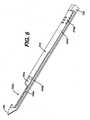
- Figure 6is a schematic cut away illustration of a portion of the cutter assembly with the cutter positioned just proximal of the lateral tissue receiving port of the needle.
- Figure 7is a schematic illustration of tissue sample stacking in a sample tube.
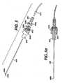
- Figure 8is a schematic cross-section illustration of a sample tube having an internal vacuum lumen.
- FIGs 1 , 1a , and 1billustrate a biopsy device 10 according to one embodiment of the present invention.
- the biopsy devicecan comprise a needle assembly 100 (shown in more detail in Figures 2 and 2a ), a main piston assembly 200 (shown in more detail in Figures 3 and 3a ), a journal assembly 300 (shown in more detail in Figures 4 and 4a ), a floating piston assembly 400 (shown in more detail in Figures 5 and 5a ), and a tube 516, which can be a clear, thin walled tube.
- Needle assembly 100 illustrated in Figures 2 and 2acan include an elongated hollow needle 104.
- Needle 104comprises an upper cutter lumen 104a, a lower vacuum lumen 104b, a lateral tissue receiving port 104c communicating with the upper cutter lumen 104a, a plurality of interlumen vacuum holes 104e extending between the upper lumen 104a and the lower lumen 104b to communicate vacuum from the lower lumen to assist in drawing tissue into the port 104c.
- a sharpened distal tissue piercing tip 106is disposed at the distal end of needle 104 and can fit within and close off the distal ends of the upper and lower lumens 104a and 104b.
- the needle 104can also include an axially enlongated needle slot 104d positioned proximal of the port 104c and the interlumen vacuum holes 104e.
- the needle slot 104dcan be used to provide communication between the upper lumen and the lower lumen of the needle 104 at a position proximal of the tissue receiving port 104c.
- the needle 104can be fixed, such as by adhesive or other suitable means, to needle support 108.
- Support 108can be captured between the upper shell housing 110 and the lower shell housing 112.
- the upper and lower housingscan be attached in any suitable manner, such as with screw fasteners, adhesive, or snap fit features.
- a vacuum inlet port 108acan be provided in needle support 108.
- Vacuum inlet port 108acan be connected to an external source of vacuum (not shown). Vacuum can be provided to the lower lumen 104b via port 108a. Vacuum supplied to lumen 104b can be applied to lateral lateral tissue receiving port 104c via two paths: 1) via the lateral vacuum holes 104e between the upper lumen 104a and lower lumen 104b; and 2) via the distal needle slot 104d and the distal portion of the upper lumen 104a.
- the main piston assembly illustrated in Figures 3 and 3acan comprise a main piston 204, an o-ring seal 208 disposed in a groove in the outer surface of piston 204 to provide sealing between piston 204 and the inside surface of tube 516, a cutter clutch 206, and a cutter 210.
- Piston 204can include a cavity 214 opening at the proximal face of the piston 204, a distally extending shaft portion 225, and a central bore 224 extending through the shaft portion 225.
- the piston 204can include a threaded portion 204b on the shaft portion 225. At the distal end of the threaded portion 204b, a circumferentially extending lip 205 can be provided. Lip 205 can engage with a complimentary slot feature 206a disposed in the proximal end of cutter clutch 206, such that cutter clutch 206 and piston 204 are coupled together for axial movement, but such that cutter clutch 206 can rotate relative piston 204 about a longitudinal axis extending through the center of the piston 204 and parallel to cutter 210.
- Cutter 210can be attached to the cutter clutch 206 by any suitable means, such as by a set screw 206c.
- Cutter clutchhas a central bore therethrough, which is aligned with the central bore 224 of piston 204 when the piston 204 and cutter clutch 206 are coupled together by lip 205 and slot feature 206a.
- Cutter 210can be in the form of a hollow tube with a sharpened distal end 210b.
- Hollow cutter 210has a central lumen 215 extending therethrough which is aligned with the central bore of the cutter clutch and the central bore 224 of piston 204.
- Cutter 210can further include a plurality of radial holes 210a which are positioned intermediate the cutter clutch 206 and the distal sharpened end 210b. The radial holes extend through the wall of the hollow cutter 210 and communicate with central lumen 215.
- Cutter clutch 206can have a generally cylindrical shaped body with surface features extending therefrom, such as engagement wings 206b. In figure 3 there are two wings 206b shown spaced at approximately 180 degree intervals around the circumference of the cutter clutch 206. Wings 206b can serve to releasably key or otherwise releasably engage clutch 206 with another member for rotation therewith, as described more fully below.
- the journal assembly 300 illustrated in Figures 4, 4a, and 4bcan comprise a journal housing 312, a motor 304 for driving rotation of a journal 306 mounted within housing 312 through a gear train.
- the gear traincan comprise a pinion gear 308, and intermediate gear 314, and a driven gear 318.
- the pinion gearcan be mounted to the drive shaft of motor 304, and the motor 304 and intermediate gear 314 can be supported by a bracket 316 which can be attached to a distal face of the journal housing 312.
- Journal 306is supported for rotation about a longitudinal axis by bearings 310.
- Journal 306includes a longitudinally extending central bore 334 therethrough.
- Journal 306has a threaded feature 306c comprising an internally threaded portion extending from proximal end of the central bore 334.
- Journal 306can also include a channel feature 306b for use in engaging the wings 206b of cutter clutch 206.
- Channel feature 306bcan comprise two longitudinally extending slots spaced about 180 degrees apart around the inner surface of bore 334, as shown in Figure 4b .
- the slots of channel feature 306bcan have a depth which is greater than the depth of the threads of threaded feature 306c.
- the slots of channel feature 306bcan extend the length of journal 306.
- the driven gearcan bear against a thrust washer, which can bear against the distal end of the journal housing to constrain journal 306 axially.
- the proximal end of the journal 306can be constrained by a journal flange 306a, which can bear against a thrust washer.
- the journal 306can be constrained radially by, and be rotatably within, bearings 310 disposed in the journal housing (312).
- the floating piston assembly shown in Figure 5 and 5acan comprise a floating piston 404 having a central bore therethrough, o-ring 404b, hollow sample tube 406, sample tube receiver 408, magnet 408b, and rear axial vacuum line 410.
- the piston 404can have a spring seat 405 for receiving the end of a spring.
- the sample tube 406can have a retaining notch 406a in the wall of the tube positioned near the open distal end 406b of tube 406.
- the sample tube 406can extend through the central bore of the piston 404 and be press fit into the proximal end of the sample tube receiver 408 such that sample tube 406 can be easily inserted and removed one or more times.
- the receiver 408has a passageway therethrough for communicating vacuum from vacuum line 410 to sample tube 406.
- the receiver 408can be configured to releasably lock onto the floating piston 404 by any suitable mechanism, such as a twist lock mechanism comprising retaining bosses 404a on the floating piston 404 and corresponding receiver slots 408a on the straw receiver 408.
- the twist lock mechanismallows the receiver 408 and sample tube 406 to be releasably coupled to the biopsy device, such that the sample tube 406 can be inserted into the device, and then withdrawn from the device once one or more samples have been received in sample tube 406.
- a circular magnet 408bcan be disposed in a recess in the distal face of the straw receiver 408.
- An o-ring 404bcan be provided in a groove on the outer surface of floating piston 404 to provide sealing with the inner surface of tube 516 as piston 404 translates within tube 516.
- the rear axial vacuum line 410can be press fit into the rear of receiver 408 and enables vacuum to be drawn through the center of the sample tube 406 as the device is operated.
- a portion of the journal assembly 300can be sized and shaped to fit inside the distal end of clear, thin-wall tube 516.
- Tube 516can be made from a lightweight transparent material, such as clear plastic or polymeric material, to permit viewing of the device during operation.
- the proximal end of the needle assembly 100can then be positioned over a reduced diameter distal end portion of the clear, thin-wall tube 516 that extends distally from a lip feature 516d of the tube 516.
- the needle assembly 100 and journal assembly 300can be attached to the thin wall tube 516 by any suitable means, such as by a plurality of screws.
- the main piston assembly 200is supported for translation within the clear, thin-walled tube 516 and is positioned proximally of the journal assembly 300.
- the main piston assembly 200is keyed to the tube 516 by a piston guide tab 204a ( Figure 3 ) on the main piston 204 and a channel feature 516a ( Figure 1a ) located on the tube 516.
- Tab 204arides in channel 516a to allow main piston assembly 200 to translate axially inside the tube 516 while preventing the main piston 204 from rotating relative to the tube 516.
- An o-ring 208 seated in a groove on the outer surface of main piston 204provides an air seal between the main piston 204 and inner surface of tube 516.
- the floating piston assembly 400can be disposed inside the clear, thin-wall tube 516 and is positioned between the main piston assembly 200 and the end cap 514.
- the end cap 514can be fastened to the proximal end of the tube 516 by any suitable means including by fasteners, snap fit, or threaded engagement.
- O-ring 404b seated in a groove on the outside surface of floating piston 404provides an air seal between the floating piston 404 and the inside surface of tube 516.
- a return spring 512is captured between the main piston assembly 200 and floating piston assembly 400.
- the distal end of the return spring 512can be seated in cavity 214 of main piston 204, and the proximal end of the return spring 512 can be seated within annular seat 405 of floating piston 404.
- the return spring 512provides constant forward (distal) biasing force against the main piston assembly 200. Therefore, when the main piston assembly 200 is in its rearward (proximal) most position, the distal end of threaded feature 204b is maintained in contact with the proximal end of a journal threaded feature 306c due to the spring force provided by spring 512.
- the biasing spring force provided by spring 512also maintains two engagement wings 206b on the cutter clutch 206 in engagement with channel slot features 306b of the journal 306. Engagement of the wings 206b with slot features 306b causes cutter clutch 206 (and so cutter 210) to rotate when journal 306 is rotated by motor 304. In the embodiment shown, piston 204 does not rotate.
- journal's internal threads 306cengages with the main piston's external threads 204b causes cutter clutch 206 (and so cutter 210) to advance in lead screw fashion at a speed based on the number of threads per inch (2.54 cm) and the speed of rotation of the journal.
- cutter clutch 206and so cutter 210 to advance in lead screw fashion at a speed based on the number of threads per inch (2.54 cm) and the speed of rotation of the journal.
- translation and rotation of cutter 210is provided by rotation of journal 306 driven by a single motor 304.
- the motor 304can be operated to rotate clockwise, advancing and rotating the cutter 210 so the distal end of the cutter 210 advances in the upper lumen of needle 104 past the tissue receiving port 104 and cuts a tissue sample through the lateral port 104c in the needle assembly 100.
- the main pistons threaded feature 204b"rides" off the distal end of the journal's threaded feature 306c, thereby preventing further translation forward.
- the motor 304can be operated to continue to rotate a predetermined number of rotations, rotating the journal's channel feature 306b and therefore the cutter 210 for additional revolutions to guarantee the tissue sample has been completely separated from the main body of tissue being sampled.
- the clutch return spring 320is compressed, pushing against the cutter clutch 206, to keep the proximal end of the main piston's threads (204b) and the distal end of the journal's threads (306c) in constant contact with each other.
- the spring 320provides a biasing force to ensure the threads will engage and the main piston assembly 200 will retract when the motor 304 is operated in reverse.
- the end cap 514can include a Hall effect sensor.
- the Hall effect sensorin conjunction with magnet 408b associated with the receiver 408, can provide a signal when the sample tube is removed from the device, which signal can be used to turn the external vacuum through tube 406 on and off, or otherwise control the external vacuum source.
- the hollow needle 104can be positioned into a tissue mass, such as with the aid of any suitable imaging device.
- the assembly of the sample tube 406, magnet 408b, receiver 408, and vacuum line 410can be inserted into and releasably coupled to the floating piston 404 using the bosses 404a.
- the external vacuum sourcecan be turned on via the Hall effect sensor 510 and the magnet 408b that is supported inside the receiver 408.
- Lever 506activates an electromechanical momentary contact switch 508 to begin rotation of motor 304 and journal 306. Rotation of journal 306 draws main piston assembly 200 forward (distally).
- vacuumcan be applied from an external source through a vacuum tube 504 and port 516b in tube 516 that communicates vacuum into a chamber 516c on the distal side of the floating piston 404. Vacuum in chamber 516c pulls the floating piston 404 forward, so that the distal end 406b of the sample tube 406 advances inside the cutter 210. With the cutter 210 fully advanced, the distal end of the sample tube 406 advances to the distal end of the needle lateral port 104c, thereby encapsulating the tissue sample with slight radial compression applied to the tissue sample.
- the vacuum to line 504can be turned off and atmospheric pressure can be provided to the distal face of the floating piston 404, so that the return spring 512 pushes the floating piston assembly 400 back to the retracted position shown in Figure 1a .
- the physicianmay then press the button 506, which activates the electromechanical switch 508 a second time, causing the motor 304 to rotate in the opposite direction, thereby retracting the cutter 210.
- the clutch return spring 320presses the piston assembly 200 back onto the journal's threaded feature 306c, so that engagement is ensured.
- the journal 306spins in the opposite direction; causing the piston assembly 200 to retract so the distal end 210b of cutter 210 is positioned just proximal of the proximal end of the lateral needle port 104c. Accordingly, the full travel of the cutter 210 can be from just proximal of the port 104c to just distal of port 104c.
- the userpresses lever 506 to activate the electromechanical switch 508 and provide motor 304 rotation in the forward direction to rotate and translate the cutter through the needle's lateral port 104c, so as to sever tissue drawn into port 104c by vacuum provided via lumen 104b.
- vacuum pressurecan again be applied via port 516b to the distal face of the floating piston 404, so that piston 404 and sample tube 406 are advanced, with the distal end of tube 406 advanced to the distal end of the needle lateral port 104c.
- the second tissue sampleis encapsulated by the sample tube 406. As the second tissue sample enters the sample tube 406, the first tissue sample is displaced rearward into the sample tube 406. In this manner, multiple samples can be stacked within a sample tube 406 until the sample tube 406 contains a plurality of tissue specimens.
- Figure 7illustrates stacking of successive tissue samples 3100A-3100C in sample tube 406.
- the sample tube inner diametercan be sized so that the cut tissue samples are slightly compressed within the sample tube.
- the usermay release the sample tube 406 by rotating the receiver 408 slightly to expose the wider portion of the slots 408a to allow the slots 408a to clear the retaining bosses 404a.
- magnet 408b within the straw receiver 408passes a Hall effect sensor 510 in end cap 514, which can provide a signal for use in turning off the external vacuum source communicating through vacuum line 410.
- a tissue retention feature in the wall of tube 406, such as rectangular notch 406a,is provided near the distal end of the sample tube 406.
- Notch 406acan allow the most recently acquired sample near the distal end of the sample tube 406 to expand or bulge slightly out of opening provided by notch 406a. The notch thereby aids in retaining the most recently obtained sample within sample tube 406.
- vacuum applied to samples from vacuum line 410 through the sample tube 406can apply a force to the distal end of the tissue sample, which can assist in balancing any axial vacuum force that may be applied to the tissue samples by vacuum provided through interlumen vacuum holes 104e.
- Other suitable tissue retention featuressuch as one or more indentations in the tube wall, could be employed to assist in retaining tissue samples.
- the usermay remove tube 406 from receiver 408.
- the usermay then cover the rectangular notch 406a with a finger, compressing the sample back into the sample tube 406, while pushing a rod through the sample tube 406 to push the samples out of the tube.
- the fingercan be removed and the sample(s) can be pushed out of the tube.
- a saline filled syringemay be attached to one end of the sample tube 406, and saline may be used to push the samples out of the tube 406.
- needle 104can include needle slot 104d between the upper cutter lumen 104a and lower vacuum lumen 104b.
- vacuumis applied from the external vacuum source through the inlet port 108a ( Figure 2 ) to the needle lower lumen 104b, vacuum is applied both through the proximal needle slit 104d and the lateral vacuum holes 104e.
- Staggered radial holes 210a(these holes can be circular, rectangular, or any other suitable shape) in the cutter 210 align with and communicate with the distal needle slot 104d as the distal end of the cutter 210 rotates and translates through the needle lateral port 104c.
- vacuumis communicated to the internal lumen of the cutter 210 from the lower lumen 104b via the distal slit 104d and the staggered radial cutter holes 210a.
- vacuumis applied both laterally to the tissue through interlumen vacuum holes 104e as well as axially through cutter 210 via the distal needle slot 104d and cutter holes 210a to assist in maximizing tissue sample size.
- Vacuum provided by vacuum line 410 through sample tube 406 and then through cutter 210can provide axial vacuum force for assisting in obtaining suitable samples through port 104c when there are no previously severed samples in sample tube 406.
- Slot 104d and cutter holes 210acan be employed to provide axial vacuum at the port 104c even if samples are present in the sample tube 406.
- Figure 8shows an alternative embodiment of sample tube 406 having an internal wall 448 to provide a first sample lumen 462 and a second vacuum lumen 464.
- Each of lumen 462 and 464can be in communication with a source of vacuum such as that provided via vacuum line 410.
- Vacuum lumen 464can employed to provide axial vacuum at port 104c when samples are present in lumen 462 of sample tube 406.
Landscapes
- Health & Medical Sciences (AREA)
- Life Sciences & Earth Sciences (AREA)
- Medical Informatics (AREA)
- Engineering & Computer Science (AREA)
- Biomedical Technology (AREA)
- Heart & Thoracic Surgery (AREA)
- Pathology (AREA)
- Molecular Biology (AREA)
- Surgery (AREA)
- Animal Behavior & Ethology (AREA)
- General Health & Medical Sciences (AREA)
- Public Health (AREA)
- Veterinary Medicine (AREA)
- Sampling And Sample Adjustment (AREA)
- Surgical Instruments (AREA)
Description
- Field of the Invention
- The present invention relates in general to biopsy devices and more particularly to devices for handling samples obtained with a biopsy device.
- Background of the Invention
- The diagnosis and treatment of patients with cancerous tumors is an ongoing area of investigation. Medical devices for obtaining tissue samples for subsequent sampling are known in the art. For instance, a biopsy instrument now marketed under the tradename MAMMOTOME is commercially available for use in obtaining breast biopsy samples.
- Various imaging techniques including X-ray, MRI, CT, and ultrasound imaging may be used with biopsy devices for use in acquiring one or more tissue samples. It can be desirable to use an image guided, percutaneous biopsy instrument which is vacuum assisted, such as the MAMMOTOME device, to acquire multiple tissue samples without removing a biopsy needle between samples.
- The following patent documents disclose various biopsy devices :
US 6,273,862 issued Aug 14,2001 ;US 6,231,522 issued May 15,2001 ;US 6,228,055 issued May 8, 2001 ;US 6,120,462 issued September 19, 2000 ;US 6,086,544 issued July 11, 2000 ;US 6,077,230 issued June 20, 2000 ;US 6,017,316 issued January 25, 2000 ;US 6,007,497 issued Dec. 28,1999 ;US 5,980,469 issued Nov. 9, 1999 ;US 5,964,716 issued Oct 12,1999 ;US 5,928,164 issued July 27, 1999 ;US 5,775,333 issued July 7, 1998 ;US 5,769,086 issued June 23, 1998 ;US 5,649,547 issued July 22, 1997 ;US 5,526,822 issued June 18,1996 ;US Patent Application publication 2003/0199753 published Oct. 23, 2003 to Hibner et al. US 6,019,733 discloses a single insertion multiple sample percutaneous biopsy apparatus and method. - The present invention provides a biopsy device as claimed in the appendant claims.
- The invention provides an apparatus useful for obtaining a biopsy sample. In one embodiment, the present invention provides a biopsy device comprising a hollow biopsy needle having a tissue receiving port; a hollow cutter advancable within the biopsy needle to sever tissue received within the tissue receiving port; and a sample tube advancable within the cutter. The sample tube can be releasably coupled to the biopsy device, so that the sample tube can be removed from the biopsy device, and tissue samples removed from the sample tube. A vacuum source can be provided in communication with the sample tube for providing axial vacuum through the cutter.
- Brief Description of the Figures
FIGURE 1 is a schematic illustration of subassemblies of a biopsy device according to one embodiment of the present invention.Figure 1a is cross-sectional schematic illustration of the biopsy device assembled as shown inFigure 1b .Figure 1b is a perspective view of a biopsy device according to one embodiment of the present invention.Figure 2 is top view illustration of the needle assembly inFigure 1 .Figure 2a is a cross-sectional illustration of the needle assembly illustrated inFigure 1 .Figure 3 is an enlarged schematic illustration of the main piston assembly shown inFigure 1 .Figure 3a is a cross-sectional schematic illustration of the main piston assembly.Figure 4 is a schematic illustration of the journal assembly shown inFigure 1 .Figure 4a is a schematic cross-sectional illustration of the journal assembly ofFigure 4 .Figure 4b is a schematic illustration of the proximal end of the journal inFigure 4a .Figure 5 is an enlarged schematic illustration of the floating piston assembly inFigure 1 .Figure 5a is a schematic cross-sectional illustration of the floating piston assembly inFigure 5 .Figure 6 is a schematic cut away illustration of a portion of the cutter assembly with the cutter positioned just proximal of the lateral tissue receiving port of the needle.Figure 7 is a schematic illustration of tissue sample stacking in a sample tube.Figure 8 is a schematic cross-section illustration of a sample tube having an internal vacuum lumen.- Detailed Description
Figures 1 ,1a , and1b illustrate abiopsy device 10 according to one embodiment of the present invention. The biopsy device can comprise a needle assembly 100 (shown in more detail inFigures 2 and 2a ), a main piston assembly 200 (shown in more detail inFigures 3 and 3a ), a journal assembly 300 (shown in more detail inFigures 4 and 4a ), a floating piston assembly 400 (shown in more detail inFigures 5 and 5a ), and atube 516, which can be a clear, thin walled tube.Needle assembly 100 illustrated inFigures 2 and 2a can include an elongatedhollow needle 104.Needle 104 comprises anupper cutter lumen 104a, alower vacuum lumen 104b, a lateraltissue receiving port 104c communicating with theupper cutter lumen 104a, a plurality ofinterlumen vacuum holes 104e extending between theupper lumen 104a and thelower lumen 104b to communicate vacuum from the lower lumen to assist in drawing tissue into theport 104c. A sharpened distaltissue piercing tip 106 is disposed at the distal end ofneedle 104 and can fit within and close off the distal ends of the upper andlower lumens needle 104 can also include an axially enlongatedneedle slot 104d positioned proximal of theport 104c and theinterlumen vacuum holes 104e. Theneedle slot 104d can be used to provide communication between the upper lumen and the lower lumen of theneedle 104 at a position proximal of thetissue receiving port 104c.- The
needle 104 can be fixed, such as by adhesive or other suitable means, to needlesupport 108.Support 108 can be captured between theupper shell housing 110 and thelower shell housing 112. The upper and lower housings can be attached in any suitable manner, such as with screw fasteners, adhesive, or snap fit features. - A
vacuum inlet port 108a can be provided inneedle support 108.Vacuum inlet port 108a can be connected to an external source of vacuum (not shown). Vacuum can be provided to thelower lumen 104b viaport 108a. Vacuum supplied tolumen 104b can be applied to lateral lateraltissue receiving port 104c via two paths: 1) via thelateral vacuum holes 104e between theupper lumen 104a andlower lumen 104b; and 2) via thedistal needle slot 104d and the distal portion of theupper lumen 104a. - The main piston assembly illustrated in
Figures 3 and 3a can comprise amain piston 204, an o-ring seal 208 disposed in a groove in the outer surface ofpiston 204 to provide sealing betweenpiston 204 and the inside surface oftube 516, acutter clutch 206, and acutter 210. Piston 204 can include acavity 214 opening at the proximal face of thepiston 204, a distally extendingshaft portion 225, and acentral bore 224 extending through theshaft portion 225. - The
piston 204 can include a threadedportion 204b on theshaft portion 225. At the distal end of the threadedportion 204b, a circumferentially extendinglip 205 can be provided.Lip 205 can engage with acomplimentary slot feature 206a disposed in the proximal end ofcutter clutch 206, such thatcutter clutch 206 andpiston 204 are coupled together for axial movement, but such thatcutter clutch 206 can rotaterelative piston 204 about a longitudinal axis extending through the center of thepiston 204 and parallel tocutter 210. Cutter 210 can be attached to thecutter clutch 206 by any suitable means, such as by aset screw 206c. Cutter clutch has a central bore therethrough, which is aligned with thecentral bore 224 ofpiston 204 when thepiston 204 andcutter clutch 206 are coupled together bylip 205 andslot feature 206a.Cutter 210 can be in the form of a hollow tube with a sharpeneddistal end 210b.Hollow cutter 210 has acentral lumen 215 extending therethrough which is aligned with the central bore of the cutter clutch and thecentral bore 224 ofpiston 204.Cutter 210 can further include a plurality ofradial holes 210a which are positioned intermediate thecutter clutch 206 and the distal sharpenedend 210b. The radial holes extend through the wall of thehollow cutter 210 and communicate withcentral lumen 215.Cutter clutch 206 can have a generally cylindrical shaped body with surface features extending therefrom, such asengagement wings 206b. Infigure 3 there are twowings 206b shown spaced at approximately 180 degree intervals around the circumference of thecutter clutch 206. Wings 206b can serve to releasably key or otherwise releasably engageclutch 206 with another member for rotation therewith, as described more fully below.- The
journal assembly 300 illustrated inFigures 4, 4a, and 4b can comprise ajournal housing 312, amotor 304 for driving rotation of ajournal 306 mounted withinhousing 312 through a gear train. The gear train can comprise apinion gear 308, andintermediate gear 314, and a drivengear 318. The pinion gear can be mounted to the drive shaft ofmotor 304, and themotor 304 andintermediate gear 314 can be supported by abracket 316 which can be attached to a distal face of thejournal housing 312. - The driven
gear 318 can be mounted tojournal 306.Journal 306 is supported for rotation about a longitudinal axis bybearings 310.Journal 306 includes a longitudinally extendingcentral bore 334 therethrough.Journal 306 has a threadedfeature 306c comprising an internally threaded portion extending from proximal end of thecentral bore 334.Journal 306 can also include achannel feature 306b for use in engaging thewings 206b ofcutter clutch 206.Channel feature 306b can comprise two longitudinally extending slots spaced about 180 degrees apart around the inner surface ofbore 334, as shown inFigure 4b . The slots ofchannel feature 306b can have a depth which is greater than the depth of the threads of threadedfeature 306c. The slots ofchannel feature 306b can extend the length ofjournal 306. - The driven gear can bear against a thrust washer, which can bear against the distal end of the journal housing to constrain
journal 306 axially. The proximal end of thejournal 306 can be constrained by ajournal flange 306a, which can bear against a thrust washer. Thejournal 306 can be constrained radially by, and be rotatably within,bearings 310 disposed in the journal housing (312). - The floating piston assembly shown in
Figure 5 and 5a can comprise a floatingpiston 404 having a central bore therethrough, o-ring 404b,hollow sample tube 406,sample tube receiver 408,magnet 408b, and rearaxial vacuum line 410. Thepiston 404 can have aspring seat 405 for receiving the end of a spring. Thesample tube 406 can have a retainingnotch 406a in the wall of the tube positioned near the opendistal end 406b oftube 406. Thesample tube 406 can extend through the central bore of thepiston 404 and be press fit into the proximal end of thesample tube receiver 408 such thatsample tube 406 can be easily inserted and removed one or more times. Thereceiver 408 has a passageway therethrough for communicating vacuum fromvacuum line 410 to sampletube 406. Thereceiver 408 can be configured to releasably lock onto the floatingpiston 404 by any suitable mechanism, such as a twist lock mechanism comprising retainingbosses 404a on the floatingpiston 404 andcorresponding receiver slots 408a on thestraw receiver 408. The twist lock mechanism allows thereceiver 408 andsample tube 406 to be releasably coupled to the biopsy device, such that thesample tube 406 can be inserted into the device, and then withdrawn from the device once one or more samples have been received insample tube 406. Acircular magnet 408b can be disposed in a recess in the distal face of thestraw receiver 408. An o-ring 404b can be provided in a groove on the outer surface of floatingpiston 404 to provide sealing with the inner surface oftube 516 aspiston 404 translates withintube 516. The rearaxial vacuum line 410 can be press fit into the rear ofreceiver 408 and enables vacuum to be drawn through the center of thesample tube 406 as the device is operated. - A portion of the
journal assembly 300 can be sized and shaped to fit inside the distal end of clear, thin-wall tube 516.Tube 516 can be made from a lightweight transparent material, such as clear plastic or polymeric material, to permit viewing of the device during operation. The proximal end of theneedle assembly 100 can then be positioned over a reduced diameter distal end portion of the clear, thin-wall tube 516 that extends distally from alip feature 516d of thetube 516. Theneedle assembly 100 andjournal assembly 300 can be attached to thethin wall tube 516 by any suitable means, such as by a plurality of screws. - The
main piston assembly 200 is supported for translation within the clear, thin-walled tube 516 and is positioned proximally of thejournal assembly 300. Themain piston assembly 200 is keyed to thetube 516 by apiston guide tab 204a (Figure 3 ) on themain piston 204 and achannel feature 516a (Figure 1a ) located on thetube 516.Tab 204a rides inchannel 516a to allowmain piston assembly 200 to translate axially inside thetube 516 while preventing themain piston 204 from rotating relative to thetube 516. An o-ring 208 seated in a groove on the outer surface ofmain piston 204 provides an air seal between themain piston 204 and inner surface oftube 516. - The floating
piston assembly 400 can be disposed inside the clear, thin-wall tube 516 and is positioned between themain piston assembly 200 and theend cap 514. Theend cap 514 can be fastened to the proximal end of thetube 516 by any suitable means including by fasteners, snap fit, or threaded engagement. O-ring 404b seated in a groove on the outside surface of floatingpiston 404 provides an air seal between the floatingpiston 404 and the inside surface oftube 516. - A
return spring 512 is captured between themain piston assembly 200 and floatingpiston assembly 400. The distal end of thereturn spring 512 can be seated incavity 214 ofmain piston 204, and the proximal end of thereturn spring 512 can be seated withinannular seat 405 of floatingpiston 404. Thereturn spring 512 provides constant forward (distal) biasing force against themain piston assembly 200. Therefore, when themain piston assembly 200 is in its rearward (proximal) most position, the distal end of threadedfeature 204b is maintained in contact with the proximal end of a journal threadedfeature 306c due to the spring force provided byspring 512. The biasing spring force provided byspring 512 also maintains twoengagement wings 206b on thecutter clutch 206 in engagement with channel slot features 306b of thejournal 306. Engagement of thewings 206b with slot features 306b causes cutter clutch 206 (and so cutter 210) to rotate whenjournal 306 is rotated bymotor 304. In the embodiment shown,piston 204 does not rotate. - Engagement of the journal's
internal threads 306c with the main piston'sexternal threads 204b causes cutter clutch 206 (and so cutter 210) to advance in lead screw fashion at a speed based on the number of threads per inch (2.54 cm) and the speed of rotation of the journal. With this mechanism, translation and rotation ofcutter 210 is provided by rotation ofjournal 306 driven by asingle motor 304. - The
motor 304 can be operated to rotate clockwise, advancing and rotating thecutter 210 so the distal end of thecutter 210 advances in the upper lumen ofneedle 104 past thetissue receiving port 104 and cuts a tissue sample through thelateral port 104c in theneedle assembly 100. Once thecutter 210 has fully translated past theneedle lateral port 104c, the main pistons threadedfeature 204b "rides" off the distal end of the journal's threadedfeature 306c, thereby preventing further translation forward. However, themotor 304 can be operated to continue to rotate a predetermined number of rotations, rotating the journal'schannel feature 306b and therefore thecutter 210 for additional revolutions to guarantee the tissue sample has been completely separated from the main body of tissue being sampled. - Once the
main piston assembly 200 has translated to its forward most (distal most) position, theclutch return spring 320 is compressed, pushing against thecutter clutch 206, to keep the proximal end of the main piston's threads (204b) and the distal end of the journal's threads (306c) in constant contact with each other. Thespring 320 provides a biasing force to ensure the threads will engage and themain piston assembly 200 will retract when themotor 304 is operated in reverse. - The
end cap 514 can include a Hall effect sensor. The Hall effect sensor in conjunction withmagnet 408b associated with thereceiver 408, can provide a signal when the sample tube is removed from the device, which signal can be used to turn the external vacuum throughtube 406 on and off, or otherwise control the external vacuum source. - The
hollow needle 104 can be positioned into a tissue mass, such as with the aid of any suitable imaging device. To begin operation of the biopsy device the assembly of thesample tube 406,magnet 408b,receiver 408, andvacuum line 410 can be inserted into and releasably coupled to the floatingpiston 404 using thebosses 404a. Upon insertion of thereceiver 408 through theend cap 514 the external vacuum source can be turned on via theHall effect sensor 510 and themagnet 408b that is supported inside thereceiver 408. - To activate the biopsy device, the physician can depress 506.
Lever 506 activates an electromechanicalmomentary contact switch 508 to begin rotation ofmotor 304 andjournal 306. Rotation ofjournal 306 drawsmain piston assembly 200 forward (distally). - Referring to
Figure 1a , after thecutter 210 has advanced forward completely to sever a tissue sample, vacuum can be applied from an external source through avacuum tube 504 andport 516b intube 516 that communicates vacuum into achamber 516c on the distal side of the floatingpiston 404. Vacuum inchamber 516c pulls the floatingpiston 404 forward, so that thedistal end 406b of thesample tube 406 advances inside thecutter 210. With thecutter 210 fully advanced, the distal end of thesample tube 406 advances to the distal end of theneedle lateral port 104c, thereby encapsulating the tissue sample with slight radial compression applied to the tissue sample. Once the tissue sample is encapsulated, the vacuum toline 504 can be turned off and atmospheric pressure can be provided to the distal face of the floatingpiston 404, so that thereturn spring 512 pushes the floatingpiston assembly 400 back to the retracted position shown inFigure 1a . - The physician may then press the
button 506, which activates the electromechanical switch 508 a second time, causing themotor 304 to rotate in the opposite direction, thereby retracting thecutter 210. Theclutch return spring 320 presses thepiston assembly 200 back onto the journal's threadedfeature 306c, so that engagement is ensured. Thejournal 306 spins in the opposite direction; causing thepiston assembly 200 to retract so thedistal end 210b ofcutter 210 is positioned just proximal of the proximal end of thelateral needle port 104c. Accordingly, the full travel of thecutter 210 can be from just proximal of theport 104c to just distal ofport 104c. - To take a second tissue sample, the user presses
lever 506 to activate theelectromechanical switch 508 and providemotor 304 rotation in the forward direction to rotate and translate the cutter through the needle'slateral port 104c, so as to sever tissue drawn intoport 104c by vacuum provided vialumen 104b. After thecutter 210 has completely separated a second tissue specimen, vacuum pressure can again be applied viaport 516b to the distal face of the floatingpiston 404, so thatpiston 404 andsample tube 406 are advanced, with the distal end oftube 406 advanced to the distal end of theneedle lateral port 104c. The second tissue sample is encapsulated by thesample tube 406. As the second tissue sample enters thesample tube 406, the first tissue sample is displaced rearward into thesample tube 406. In this manner, multiple samples can be stacked within asample tube 406 until thesample tube 406 contains a plurality of tissue specimens. Figure 7 illustrates stacking ofsuccessive tissue samples 3100A-3100C insample tube 406. The sample tube inner diameter can be sized so that the cut tissue samples are slightly compressed within the sample tube.- When the
tube 406 contains the desired number of severed tissue specimens, the user may release thesample tube 406 by rotating thereceiver 408 slightly to expose the wider portion of theslots 408a to allow theslots 408a to clear the retainingbosses 404a. When thereceiver 408 is removed with thesample tube 406 attached,magnet 408b within thestraw receiver 408 passes aHall effect sensor 510 inend cap 514, which can provide a signal for use in turning off the external vacuum source communicating throughvacuum line 410. - In one embodiment, a tissue retention feature in the wall of
tube 406, such asrectangular notch 406a, is provided near the distal end of thesample tube 406.Notch 406a can allow the most recently acquired sample near the distal end of thesample tube 406 to expand or bulge slightly out of opening provided bynotch 406a. The notch thereby aids in retaining the most recently obtained sample withinsample tube 406. Additionally; vacuum applied to samples fromvacuum line 410 through thesample tube 406 can apply a force to the distal end of the tissue sample, which can assist in balancing any axial vacuum force that may be applied to the tissue samples by vacuum provided throughinterlumen vacuum holes 104e. Other suitable tissue retention features, such as one or more indentations in the tube wall, could be employed to assist in retaining tissue samples. - To remove tissue samples from the
sample tube 406 once thetube 406 has been removed fromtube 516, the user may removetube 406 fromreceiver 408. The user may then cover therectangular notch 406a with a finger, compressing the sample back into thesample tube 406, while pushing a rod through thesample tube 406 to push the samples out of the tube. Once the sample has traveled past therectangular notch 406a, the finger can be removed and the sample(s) can be pushed out of the tube. Alternatively, a saline filled syringe may be attached to one end of thesample tube 406, and saline may be used to push the samples out of thetube 406. - Referring to
Figure 6 ,needle 104 can includeneedle slot 104d between theupper cutter lumen 104a andlower vacuum lumen 104b. When vacuum is applied from the external vacuum source through theinlet port 108a (Figure 2 ) to the needlelower lumen 104b, vacuum is applied both through theproximal needle slit 104d and thelateral vacuum holes 104e. Staggeredradial holes 210a (these holes can be circular, rectangular, or any other suitable shape) in thecutter 210 align with and communicate with thedistal needle slot 104d as the distal end of thecutter 210 rotates and translates through theneedle lateral port 104c. Therefore, vacuum is communicated to the internal lumen of thecutter 210 from thelower lumen 104b via thedistal slit 104d and the staggeredradial cutter holes 210a. In this way, during sampling, and even with tissue samples intube 406, vacuum is applied both laterally to the tissue throughinterlumen vacuum holes 104e as well as axially throughcutter 210 via thedistal needle slot 104d andcutter holes 210a to assist in maximizing tissue sample size. Vacuum provided byvacuum line 410 throughsample tube 406 and then throughcutter 210 can provide axial vacuum force for assisting in obtaining suitable samples throughport 104c when there are no previously severed samples insample tube 406.Slot 104d andcutter holes 210a can be employed to provide axial vacuum at theport 104c even if samples are present in thesample tube 406. Figure 8 shows an alternative embodiment ofsample tube 406 having aninternal wall 448 to provide afirst sample lumen 462 and asecond vacuum lumen 464. Each oflumen vacuum line 410.Vacuum lumen 464 can employed to provide axial vacuum atport 104c when samples are present inlumen 462 ofsample tube 406.- While the present invention has been illustrated by description of several embodiments, it is not the intention of the applicant to restrict or limit the scope of the appended claims to such detail. Numerous variations, changes, and substitutions will occur to those skilled in the art without departing from the scope of the invention. Moreover, the structure of each element associated with the present invention can be alternatively described as a means for providing the function performed by the element. Accordingly, it is intended that the invention be limited only by the scope of the appended claims.
Claims (14)
- A biopsy device (10) comprising:a hollow biopsy needle (104) having a tissue receiving port (104c);a hollow cutter (210) advanceable within a cutter lumen (104a) of the biopsy needle (104) to sever tissue received within the tissue receiving port (104c);a vacuum lumen (104b);a plurality of interlumen vacuum holes (104e) extending between the cutter lumen (104a) and the vacuum lumen (104b); anda sample tube (406) having an open distal end, the sample tube (406) supported on the biopsy device (10) and advanceable within the cutter (210)characterised in that the cutter (210) has a plurality of cutter holes (210a) spaced from a distal end of the cutter (210);a needle slot (104d) between the cutter lumen (104a) and the vacuum lumen (104b); wherein in use the plurality of cutter holes (210a) are aligned with the needle slot (104d) such that a vacuum is communicated both laterally through the interlumen vacuum holes (104e) from the vacuum lumen (104b) as well as axially through the cutter (210) from the vacuum lumen (104b), via the needle slot (104d) and the plurality of cutter holes (210a).
- The biopsy device of Claim 1 wherein the sample tube (406) is releasably coupled to the biopsy device (10).
- The biopsy device of Claim 1 comprising a vacuum source in communication with the sample tube (406).
- The biopsy device of Claim 1 wherein the sample tube (406) is advanced by fluid pressure.
- The biopsy device of Claim 1 wherein the sample tube (406) is advanced pneumatically.
- The biopsy device of Claim 1 comprising a piston (404) operatively associated with the sample tube (406).
- The biopsy device of Claim 1 comprising apparatus (200, 300) for advancing and retracting the cutter within the biopsy needle.
- The biopsy device of Claim 1 comprising apparatus (400) for advancing and retracting the sample tube within the cutter.
- The device of Claim 1 wherein the hollow needle (104) comprises a lateral tissue receiving port (104c) spaced from the distal end of the needle (104).
- The device of Claim 1 wherein the sample tube (406) comprises a vacuum lumen (464) and a sample lumen (462).
- The device of Claim 1 wherein the sample tube (406) comprises a tube wall feature for retaining tissue samples.
- The device of Claim 11 wherein the tube wall feature comprises a notch (406a) disposed adjacent the distal end of the sample tube.
- The biopsy device of Claim 1 comprising a rotating journal (306) for rotating and advancing the cutter.
- The biopsy device of claim 1 further comprising a drive mechanism (300) for advancing and rotating the cutter (210) within the biopsy needle (104), wherein the drive mechanism (300) comprises an internally threaded, rotatably driven component (306) for advancing and rotating the cutter (210).
Applications Claiming Priority (3)
| Application Number | Priority Date | Filing Date | Title |
|---|---|---|---|
| US43254602P | 2002-12-11 | 2002-12-11 | |
| US432546P | 2002-12-11 | ||
| PCT/US2003/039364WO2004052212A1 (en) | 2002-12-11 | 2003-12-11 | Biopsy device with sample tube |
Publications (3)
| Publication Number | Publication Date |
|---|---|
| EP1575431A1 EP1575431A1 (en) | 2005-09-21 |
| EP1575431A4 EP1575431A4 (en) | 2008-04-09 |
| EP1575431B1true EP1575431B1 (en) | 2009-09-09 |
Family
ID=32507961
Family Applications (1)
| Application Number | Title | Priority Date | Filing Date |
|---|---|---|---|
| EP03790455AExpired - LifetimeEP1575431B1 (en) | 2002-12-11 | 2003-12-11 | Biopsy device with sample tube |
Country Status (8)
| Country | Link |
|---|---|
| US (1) | US7740597B2 (en) |
| EP (1) | EP1575431B1 (en) |
| JP (1) | JP4541897B2 (en) |
| CN (1) | CN100473358C (en) |
| AU (1) | AU2003293505B2 (en) |
| CA (1) | CA2508138A1 (en) |
| DE (1) | DE60329222D1 (en) |
| WO (1) | WO2004052212A1 (en) |
Families Citing this family (137)
| Publication number | Priority date | Publication date | Assignee | Title |
|---|---|---|---|---|
| US7189206B2 (en) | 2003-02-24 | 2007-03-13 | Senorx, Inc. | Biopsy device with inner cutter |
| US8282573B2 (en) | 2003-02-24 | 2012-10-09 | Senorx, Inc. | Biopsy device with selectable tissue receiving aperture orientation and site illumination |
| EP1524940B1 (en) | 2002-03-19 | 2011-08-24 | Bard Dublin ITC Limited | Biopsy device and biopsy needle module that can be inserted into the biopsy device |
| US8109885B2 (en) | 2002-03-19 | 2012-02-07 | C. R. Bard, Inc. | Biopsy device for removing tissue specimens using a vacuum |
| US9451968B2 (en) | 2002-05-31 | 2016-09-27 | Vidacare LLC | Powered drivers, intraosseous devices and methods to access bone marrow |
| US11298202B2 (en) | 2002-05-31 | 2022-04-12 | Teleflex Life Sciences Limited | Biopsy devices and related methods |
| US20070049945A1 (en) | 2002-05-31 | 2007-03-01 | Miller Larry J | Apparatus and methods to install, support and/or monitor performance of intraosseous devices |
| US7811260B2 (en) | 2002-05-31 | 2010-10-12 | Vidacare Corporation | Apparatus and method to inject fluids into bone marrow and other target sites |
| US9314228B2 (en) | 2002-05-31 | 2016-04-19 | Vidacare LLC | Apparatus and method for accessing the bone marrow |
| EP2039298B1 (en) | 2002-05-31 | 2017-10-25 | Vidacare LLC | Apparatus to access bone marrow |
| US9072543B2 (en) | 2002-05-31 | 2015-07-07 | Vidacare LLC | Vascular access kits and methods |
| US8668698B2 (en) | 2002-05-31 | 2014-03-11 | Vidacare Corporation | Assembly for coupling powered driver with intraosseous device |
| US10973545B2 (en) | 2002-05-31 | 2021-04-13 | Teleflex Life Sciences Limited | Powered drivers, intraosseous devices and methods to access bone marrow |
| US10973532B2 (en) | 2002-05-31 | 2021-04-13 | Teleflex Life Sciences Limited | Powered drivers, intraosseous devices and methods to access bone marrow |
| US7951089B2 (en) | 2002-05-31 | 2011-05-31 | Vidacare Corporation | Apparatus and methods to harvest bone and bone marrow |
| US8641715B2 (en) | 2002-05-31 | 2014-02-04 | Vidacare Corporation | Manual intraosseous device |
| US8142365B2 (en) | 2002-05-31 | 2012-03-27 | Vidacare Corporation | Apparatus and method for accessing the bone marrow of the sternum |
| US8690791B2 (en) | 2002-05-31 | 2014-04-08 | Vidacare Corporation | Apparatus and method to access the bone marrow |
| US7850620B2 (en) | 2002-05-31 | 2010-12-14 | Vidacare Corporation | Biopsy devices and related methods |
| US11337728B2 (en) | 2002-05-31 | 2022-05-24 | Teleflex Life Sciences Limited | Powered drivers, intraosseous devices and methods to access bone marrow |
| US8123698B2 (en)* | 2002-10-07 | 2012-02-28 | Suros Surgical Systems, Inc. | System and method for minimally invasive disease therapy |
| DE10314240B4 (en) | 2003-03-29 | 2025-05-28 | Bard Dublin Itc Ltd. | Pressure generation unit |
| US9504477B2 (en) | 2003-05-30 | 2016-11-29 | Vidacare LLC | Powered driver |
| US8172770B2 (en)* | 2005-09-28 | 2012-05-08 | Suros Surgical Systems, Inc. | System and method for minimally invasive disease therapy |
| US20120289859A9 (en)* | 2003-08-27 | 2012-11-15 | Nicoson Zachary R | System and method for minimally invasive disease therapy |
| US7419472B2 (en)* | 2003-09-30 | 2008-09-02 | Ethicon Endo-Surgery, Inc. | Biopsy instrument with internal specimen collection mechanism |
| US9408592B2 (en) | 2003-12-23 | 2016-08-09 | Senorx, Inc. | Biopsy device with aperture orientation and improved tip |
| CN101536926B (en) | 2004-01-26 | 2012-07-18 | 维达保健公司 | Manual interosseous device |
| US7815642B2 (en) | 2004-01-26 | 2010-10-19 | Vidacare Corporation | Impact-driven intraosseous needle |
| JP4814229B2 (en) | 2004-07-09 | 2011-11-16 | バード ペリフェラル ヴァスキュラー インコーポレイテッド | Transport device for biopsy device |
| US7740594B2 (en)* | 2004-09-29 | 2010-06-22 | Ethicon Endo-Surgery, Inc. | Cutter for biopsy device |
| US7740596B2 (en)* | 2004-09-29 | 2010-06-22 | Ethicon Endo-Surgery, Inc. | Biopsy device with sample storage |
| US20060074344A1 (en)* | 2004-09-29 | 2006-04-06 | Hibner John A | Fluid control for biopsy device |
| US20060074345A1 (en) | 2004-09-29 | 2006-04-06 | Hibner John A | Biopsy apparatus and method |
| US7276032B2 (en)* | 2004-09-29 | 2007-10-02 | Ethicon Endo-Surgery, Inc. | Biopsy apparatus and method |
| US8998848B2 (en) | 2004-11-12 | 2015-04-07 | Vidacare LLC | Intraosseous device and methods for accessing bone marrow in the sternum and other target areas |
| US8343071B2 (en) | 2004-12-16 | 2013-01-01 | Senorx, Inc. | Biopsy device with aperture orientation and improved tip |
| US7611474B2 (en)* | 2004-12-29 | 2009-11-03 | Ethicon Endo-Surgery, Inc. | Core sampling biopsy device with short coupled MRI-compatible driver |
| US7517321B2 (en) | 2005-01-31 | 2009-04-14 | C. R. Bard, Inc. | Quick cycle biopsy system |
| US20060184063A1 (en)* | 2005-02-15 | 2006-08-17 | Miller Michael E | Single motor handheld biopsy device |
| US20060200041A1 (en)* | 2005-03-04 | 2006-09-07 | Ethicon Endo-Surgery, Inc. | Biopsy device incorporating an adjustable probe sleeve |
| US7517322B2 (en)* | 2005-03-04 | 2009-04-14 | Ethicon Endo-Surgery, Inc. | Biopsy device with variable side aperture |
| US20080004545A1 (en) | 2005-08-05 | 2008-01-03 | Garrison William A | Trigger Fired Radial Plate Specimen Retrieval Biopsy Instrument |
| US8317725B2 (en) | 2005-08-05 | 2012-11-27 | Senorx, Inc. | Biopsy device with fluid delivery to tissue specimens |
| USRE46135E1 (en) | 2005-08-05 | 2016-09-06 | Devicor Medical Products, Inc. | Vacuum syringe assisted biopsy device |
| US7662109B2 (en)* | 2006-02-01 | 2010-02-16 | Ethicon Endo-Surgery, Inc. | Biopsy device with replaceable probe incorporating static vacuum source dual valve sample stacking retrieval and saline flush |
| US7572236B2 (en) | 2005-08-05 | 2009-08-11 | Senorx, Inc. | Biopsy device with fluid delivery to tissue specimens |
| US7828748B2 (en)* | 2005-08-05 | 2010-11-09 | Devicor Medical Products, Inc. | Vacuum syringe assisted biopsy device |
| US7867173B2 (en)* | 2005-08-05 | 2011-01-11 | Devicor Medical Products, Inc. | Biopsy device with replaceable probe and incorporating vibration insertion assist and static vacuum source sample stacking retrieval |
| US7854707B2 (en) | 2005-08-05 | 2010-12-21 | Devicor Medical Products, Inc. | Tissue sample revolver drum biopsy device |
| US7896817B2 (en) | 2005-08-05 | 2011-03-01 | Devicor Medical Products, Inc. | Biopsy device with manually rotated sample barrel |
| ES2539578T3 (en) | 2005-08-10 | 2015-07-02 | C.R. Bard, Inc. | Multi-sample biopsy device and single insert with various transport systems |
| JP4991723B2 (en) | 2005-08-10 | 2012-08-01 | シー・アール・バード・インコーポレーテッド | Single insertion multiple sampling biopsy device with integrated marker |
| EP1921998B8 (en) | 2005-08-10 | 2021-07-07 | C.R.Bard, Inc. | Single-insertion, multiple sampling biopsy device with linear drive |
| US20080200834A1 (en)* | 2005-09-28 | 2008-08-21 | Mark Joseph L | Introducer device for improved imaging |
| US7491177B2 (en)* | 2006-02-03 | 2009-02-17 | Ethicon Endo-Surgery, Inc. | Biopsy needle and method |
| US7766843B2 (en)* | 2006-03-03 | 2010-08-03 | Ethicon Endo-Surgery, Inc. | Biopsy method |
| US7670299B2 (en)* | 2006-03-07 | 2010-03-02 | Ethincon Endo-Surgery, Inc. | Device for minimally invasive internal tissue removal |
| US7806834B2 (en)* | 2006-03-07 | 2010-10-05 | Devicor Medical Products, Inc. | Device for minimally invasive internal tissue removal |
| US7465278B2 (en)* | 2006-03-29 | 2008-12-16 | Ethicon Endo-Surgery, Inc. | Device for minimally invasive internal tissue removal |
| US7585547B2 (en)* | 2006-04-13 | 2009-09-08 | Solopower, Inc. | Method and apparatus to form thin layers of materials on a base |
| EP3417792B1 (en) | 2006-08-21 | 2022-03-02 | C. R. Bard, Inc. | Self-contained handheld biopsy needle |
| EP3189787B1 (en) | 2006-09-12 | 2019-01-09 | Teleflex Medical Devices S.à.r.l. | Medical procedures trays and related methods |
| EP2068743B1 (en) | 2006-09-12 | 2017-03-15 | Vidacare LLC | Medical procedures trays, kits and related methods |
| EP2073728B1 (en) | 2006-09-12 | 2018-11-07 | Teleflex Medical Devices S.à.r.l. | Biopsy device |
| US8944069B2 (en) | 2006-09-12 | 2015-02-03 | Vidacare Corporation | Assemblies for coupling intraosseous (IO) devices to powered drivers |
| SI2086418T1 (en) | 2006-10-06 | 2011-05-31 | Bard Peripheral Vascular Inc | Tissue handling system with reduced operator exposure |
| US8262586B2 (en) | 2006-10-24 | 2012-09-11 | C. R. Bard, Inc. | Large sample low aspect ratio biopsy needle |
| US8974410B2 (en) | 2006-10-30 | 2015-03-10 | Vidacare LLC | Apparatus and methods to communicate fluids and/or support intraosseous devices |
| US7981049B2 (en) | 2006-12-13 | 2011-07-19 | Devicor Medical Products, Inc. | Engagement interface for biopsy system vacuum module |
| US7938786B2 (en)* | 2006-12-13 | 2011-05-10 | Devicor Medical Products, Inc. | Vacuum timing algorithm for biopsy device |
| US8251916B2 (en) | 2006-12-13 | 2012-08-28 | Devicor Medical Products, Inc. | Revolving tissue sample holder for biopsy device |
| CN102217954B (en)* | 2006-12-13 | 2013-11-06 | 伊西康内外科公司 | Biopsy device and biopsy sample storing assembly |
| US8480595B2 (en) | 2006-12-13 | 2013-07-09 | Devicor Medical Products, Inc. | Biopsy device with motorized needle cocking |
| EP1932482B1 (en)* | 2006-12-13 | 2010-04-28 | Ethicon Endo-Surgery, Inc. | Biopsy sample storage |
| US20130324882A1 (en)* | 2012-05-30 | 2013-12-05 | Devicor Medical Products, Inc. | Control for biopsy device |
| US8702623B2 (en) | 2008-12-18 | 2014-04-22 | Devicor Medical Products, Inc. | Biopsy device with discrete tissue chambers |
| US9345457B2 (en) | 2006-12-13 | 2016-05-24 | Devicor Medical Products, Inc. | Presentation of biopsy sample by biopsy device |
| US20140039343A1 (en) | 2006-12-13 | 2014-02-06 | Devicor Medical Products, Inc. | Biopsy system |
| US7858038B2 (en) | 2007-11-20 | 2010-12-28 | Devicor Medical Products, Inc. | Biopsy device with illuminated tissue holder |
| US8052616B2 (en) | 2007-11-20 | 2011-11-08 | Devicor Medical Products, Inc. | Biopsy device with fine pitch drive train |
| US7575556B2 (en)* | 2007-11-20 | 2009-08-18 | Ethicon Endo-Surgery, Inc. | Deployment device interface for biopsy device |
| US9039634B2 (en) | 2007-11-20 | 2015-05-26 | Devicor Medical Products, Inc. | Biopsy device tissue sample holder rotation control |
| US7806835B2 (en) | 2007-11-20 | 2010-10-05 | Devicor Medical Products, Inc. | Biopsy device with sharps reduction feature |
| US8454531B2 (en) | 2007-11-20 | 2013-06-04 | Devicor Medical Products, Inc. | Icon-based user interface on biopsy system control module |
| WO2009079155A2 (en)* | 2007-11-20 | 2009-06-25 | The Cleveland Clinic Foundation | Method and apparatus for tissue sampling |
| US8241225B2 (en) | 2007-12-20 | 2012-08-14 | C. R. Bard, Inc. | Biopsy device |
| US8057402B2 (en)* | 2007-12-27 | 2011-11-15 | Devicor Medical Products, Inc. | Vacuum sensor and pressure pump for tetherless biopsy device |
| US7854706B2 (en)* | 2007-12-27 | 2010-12-21 | Devicor Medical Products, Inc. | Clutch and valving system for tetherless biopsy device |
| US20090216151A1 (en)* | 2008-02-27 | 2009-08-27 | Speeg Trevor W V | Biopsy Probe With Hypodermic Lumen |
| US8162850B2 (en)* | 2008-12-16 | 2012-04-24 | Devicor Medical Products, Inc. | Hand actuated tetherless biopsy device with scissors grip |
| US8167815B2 (en)* | 2008-12-18 | 2012-05-01 | Devicor Medical Products, Inc. | Biopsy device with retractable cutter |
| US8366635B2 (en) | 2008-12-18 | 2013-02-05 | Devicor Medical Products, Inc. | Biopsy probe and targeting set interface |
| WO2010107424A1 (en) | 2009-03-16 | 2010-09-23 | C.R. Bard, Inc. | Biopsy device having rotational cutting |
| AU2009344276B2 (en) | 2009-04-15 | 2014-06-05 | C.R. Bard, Inc. | Biopsy apparatus having integrated fluid management |
| US8206316B2 (en) | 2009-06-12 | 2012-06-26 | Devicor Medical Products, Inc. | Tetherless biopsy device with reusable portion |
| US9173641B2 (en) | 2009-08-12 | 2015-11-03 | C. R. Bard, Inc. | Biopsy apparatus having integrated thumbwheel mechanism for manual rotation of biopsy cannula |
| US8430824B2 (en) | 2009-10-29 | 2013-04-30 | Bard Peripheral Vascular, Inc. | Biopsy driver assembly having a control circuit for conserving battery power |
| US8485989B2 (en) | 2009-09-01 | 2013-07-16 | Bard Peripheral Vascular, Inc. | Biopsy apparatus having a tissue sample retrieval mechanism |
| US8283890B2 (en) | 2009-09-25 | 2012-10-09 | Bard Peripheral Vascular, Inc. | Charging station for battery powered biopsy apparatus |
| JP5703299B2 (en)* | 2009-09-07 | 2015-04-15 | サノフィ−アベンティス・ドイチュラント・ゲゼルシャフト・ミット・ベシュレンクテル・ハフツング | Drive mechanism for drug delivery device |
| US8597206B2 (en) | 2009-10-12 | 2013-12-03 | Bard Peripheral Vascular, Inc. | Biopsy probe assembly having a mechanism to prevent misalignment of components prior to installation |
| EP2493390B1 (en)* | 2009-10-30 | 2014-12-31 | Cook Medical Technologies LLC | System for performing a full thickness tissue biopsy |
| US20110105946A1 (en)* | 2009-10-31 | 2011-05-05 | Sorensen Peter L | Biopsy system with infrared communications |
| KR101148187B1 (en)* | 2009-12-03 | 2012-05-23 | 주식회사 엠아이텍 | Biopsy needle device |
| JP2013521994A (en)* | 2010-03-24 | 2013-06-13 | ユナイテッド ステイツ エンドスコピー グループ,インコーポレイテッド | Multiple biopsy device |
| FR2961087B1 (en)* | 2010-06-09 | 2013-06-28 | Allflex Europ | TOOL FOR SAMPLING AN ANIMAL TISSUE SAMPLE. |
| US9220485B2 (en) | 2010-08-28 | 2015-12-29 | Endochoice, Inc. | Tissue collection and separation device |
| US8544338B2 (en)* | 2011-02-21 | 2013-10-01 | Fracturelab, Llc | Fatigue crack growth test apparatus |
| US9060759B2 (en) | 2011-03-31 | 2015-06-23 | Cook Medical Technologies Llc | Adjustable-throw biopsy needle |
| KR20140050010A (en)* | 2011-06-17 | 2014-04-28 | 사노피-아벤티스 도이칠란트 게엠베하 | Cartridge holder assembly for drug delivery devices |
| CN104039236B (en) | 2011-10-15 | 2016-06-15 | 转化医药7有限责任公司 | Soft tissue core biopsy device and method |
| EP2838435B1 (en) | 2012-04-16 | 2020-03-25 | Hathaway, Jeff M. | Biopsy device |
| US9474511B2 (en) | 2012-10-08 | 2016-10-25 | Devicor Medical Products, Inc. | Tissue biopsy device with selectively rotatable linked thumbwheel and tissue sample holder |
| GB201301866D0 (en)* | 2013-02-01 | 2013-03-20 | Olberon Ltd | Needle location device |
| US20140257253A1 (en)* | 2013-03-11 | 2014-09-11 | Boston Scientific Scimed, Inc. | Medical device handles and related methods of use |
| US10092276B2 (en) | 2013-03-15 | 2018-10-09 | Cook Medical Technologies Llc | Tissue acquisition device with indication system |
| CA2902221A1 (en) | 2013-03-20 | 2014-09-25 | Bard Peripheral Vascular, Inc. | Biopsy device |
| US9463001B2 (en) | 2013-05-28 | 2016-10-11 | Transmed7, Llc | Soft tissue coring biopsy devices and methods |
| US9155527B2 (en) | 2013-08-22 | 2015-10-13 | Transmed7, Llc | Soft tissue coring biopsy devices and methods |
| EP3043719B1 (en) | 2013-09-12 | 2022-04-13 | Transmed7, LLC | Tissue coring biopsy devices |
| ES2726985T3 (en) | 2013-11-05 | 2019-10-11 | Bard Inc C R | Biopsy device that has integrated vacuum |
| WO2016178656A1 (en) | 2015-05-01 | 2016-11-10 | C. R. Bard, Inc. | Biopsy device |
| CN106388872A (en)* | 2016-09-28 | 2017-02-15 | 广西医科大学第附属医院 | Living tissue puncturing and sampling needle |
| CN106976199B (en)* | 2017-04-07 | 2022-12-20 | 江苏康宏医疗科技有限公司 | Forming device of spring tube and core bar integrated injection molding rod assembly |
| US11116483B2 (en) | 2017-05-19 | 2021-09-14 | Merit Medical Systems, Inc. | Rotating biopsy needle |
| US11844500B2 (en) | 2017-05-19 | 2023-12-19 | Merit Medical Systems, Inc. | Semi-automatic biopsy needle device and methods of use |
| US11793498B2 (en) | 2017-05-19 | 2023-10-24 | Merit Medical Systems, Inc. | Biopsy needle devices and methods of use |
| CN108186059B (en)* | 2018-03-13 | 2020-07-28 | 湖州市妇幼保健院 | Gastrointestinal endoscope biopsy picking device |
| CN109009344B (en)* | 2018-07-24 | 2020-10-30 | 西安卓恰医疗器械有限公司 | Puncture locator with replaceable needle |
| US12232710B2 (en)* | 2018-09-28 | 2025-02-25 | Praxis Holding Llc | Oscillating syringe system |
| US10765411B2 (en) | 2018-09-28 | 2020-09-08 | John Steele Fisher | Oscillating syringe system |
| US20220096065A1 (en)* | 2018-09-28 | 2022-03-31 | Praxis Holding Llc | Oscillating syringe system and needle |
| US12295556B2 (en) | 2019-09-27 | 2025-05-13 | Merit Medical Systems, Inc. | Rotation biopsy system and handle |
| US12150627B2 (en) | 2019-12-11 | 2024-11-26 | Merit Medical Systems, Inc. | Bone biopsy device and related methods |
| US20250134499A1 (en)* | 2021-09-29 | 2025-05-01 | The Johns Hopkins University | Biopsy needle accessory |
| CN119791734B (en)* | 2025-03-03 | 2025-08-19 | 湖南省中医药研究院 | Sampling device for tumor tissue |
Family Cites Families (27)
| Publication number | Priority date | Publication date | Assignee | Title |
|---|---|---|---|---|
| US4651753A (en)* | 1984-10-12 | 1987-03-24 | Jayco Pharmaceuticals | Endoscopic multiple biopsy instrument |
| US5797907A (en)* | 1989-11-06 | 1998-08-25 | Mectra Labs, Inc. | Electrocautery cutter |
| US5183052A (en)* | 1990-11-07 | 1993-02-02 | Terwilliger Richard A | Automatic biopsy instrument with cutting cannula |
| US5195533A (en)* | 1992-05-08 | 1993-03-23 | Boston Scientific Corporation | Biopsy needle instrument for storing multiple specimens |
| US5871453A (en)* | 1994-02-08 | 1999-02-16 | Boston Scientific Corporation | Moveable sample tube multiple biopsy sampling device |
| US5649547A (en)* | 1994-03-24 | 1997-07-22 | Biopsys Medical, Inc. | Methods and devices for automated biopsy and collection of soft tissue |
| US5526822A (en)* | 1994-03-24 | 1996-06-18 | Biopsys Medical, Inc. | Method and apparatus for automated biopsy and collection of soft tissue |
| JPH10508504A (en)* | 1994-09-16 | 1998-08-25 | バイオプシス メディカル インコーポレイテッド | Method and apparatus for identifying and marking tissue |
| US5769086A (en)* | 1995-12-06 | 1998-06-23 | Biopsys Medical, Inc. | Control system and method for automated biopsy device |
| CA2275249C (en)* | 1997-01-30 | 2004-03-23 | Boston Scientific Corporation | Pneumatically actuated tissue sampling device |
| US6017316A (en)* | 1997-06-18 | 2000-01-25 | Biopsys Medical | Vacuum control system and method for automated biopsy device |
| US6050955A (en)* | 1997-09-19 | 2000-04-18 | United States Surgical Corporation | Biopsy apparatus and method |
| US6019733A (en)* | 1997-09-19 | 2000-02-01 | United States Surgical Corporation | Biopsy apparatus and method |
| US6517498B1 (en)* | 1998-03-03 | 2003-02-11 | Senorx, Inc. | Apparatus and method for tissue capture |
| US6077230A (en)* | 1998-05-14 | 2000-06-20 | Ethicon Endo-Surgery, Inc. | Biopsy instrument with removable extractor |
| US5964716A (en)* | 1998-05-14 | 1999-10-12 | Ethicon Endo-Surgery, Inc. | Method of use for a multi-port biopsy instrument |
| US5944673A (en)* | 1998-05-14 | 1999-08-31 | Ethicon Endo-Surgery, Inc. | Biopsy instrument with multi-port needle |
| US6007497A (en)* | 1998-06-30 | 1999-12-28 | Ethicon Endo-Surgery, Inc. | Surgical biopsy device |
| CA2287087C (en)* | 1998-10-23 | 2007-12-04 | Ethicon Endo-Surgery, Inc. | Surgical device for the collection of soft tissue |
| JP4559630B2 (en)* | 1998-11-25 | 2010-10-13 | ユナイテッド ステイツ サージカル コーポレイション | Biopsy system |
| US6120462A (en)* | 1999-03-31 | 2000-09-19 | Ethicon Endo-Surgery, Inc. | Control method for an automated surgical biopsy device |
| US6086544A (en)* | 1999-03-31 | 2000-07-11 | Ethicon Endo-Surgery, Inc. | Control apparatus for an automated surgical biopsy device |
| US6231522B1 (en)* | 2000-02-18 | 2001-05-15 | Ethicon Endo-Surgery, Inc. | Biopsy instrument with breakable sample segments |
| US6712773B1 (en)* | 2000-09-11 | 2004-03-30 | Tyco Healthcare Group Lp | Biopsy system |
| US6419641B1 (en)* | 2000-11-28 | 2002-07-16 | Promex, Llc | Flexible tip medical instrument |
| US7438692B2 (en)* | 2002-10-18 | 2008-10-21 | Mark Tsonton | Localization mechanism for an MRI compatible biopsy device |
| US7419472B2 (en)* | 2003-09-30 | 2008-09-02 | Ethicon Endo-Surgery, Inc. | Biopsy instrument with internal specimen collection mechanism |
- 2003
- 2003-12-10USUS10/732,843patent/US7740597B2/ennot_activeExpired - Fee Related
- 2003-12-11JPJP2004558683Apatent/JP4541897B2/ennot_activeExpired - Fee Related
- 2003-12-11AUAU2003293505Apatent/AU2003293505B2/ennot_activeCeased
- 2003-12-11DEDE60329222Tpatent/DE60329222D1/ennot_activeExpired - Lifetime
- 2003-12-11CNCNB2003801055887Apatent/CN100473358C/ennot_activeExpired - Fee Related
- 2003-12-11EPEP03790455Apatent/EP1575431B1/ennot_activeExpired - Lifetime
- 2003-12-11CACA002508138Apatent/CA2508138A1/ennot_activeAbandoned
- 2003-12-11WOPCT/US2003/039364patent/WO2004052212A1/enactiveApplication Filing
Also Published As
| Publication number | Publication date |
|---|---|
| DE60329222D1 (en) | 2009-10-22 |
| EP1575431A1 (en) | 2005-09-21 |
| AU2003293505B2 (en) | 2007-12-13 |
| US20040153003A1 (en) | 2004-08-05 |
| JP2006509545A (en) | 2006-03-23 |
| EP1575431A4 (en) | 2008-04-09 |
| CN1722986A (en) | 2006-01-18 |
| HK1082172A1 (en) | 2006-06-02 |
| CA2508138A1 (en) | 2004-06-24 |
| CN100473358C (en) | 2009-04-01 |
| WO2004052212A1 (en) | 2004-06-24 |
| US7740597B2 (en) | 2010-06-22 |
| JP4541897B2 (en) | 2010-09-08 |
| AU2003293505A1 (en) | 2004-06-30 |
Similar Documents
| Publication | Publication Date | Title |
|---|---|---|
| EP1575431B1 (en) | Biopsy device with sample tube | |
| US7351210B2 (en) | Biopsy device with piston advance | |
| US9907542B2 (en) | Biopsy device with translating valve member | |
| CA2576477C (en) | Biopsy device with replaceable probe incorporating static vacuum source dual valve sample stacking retrieval and saline flush | |
| EP0808129B1 (en) | Device for automated biopsy and collection of soft tissue | |
| HK1082172B (en) | Biopsy device with sample tube | |
| HK1170405A (en) | Biopsy device with translating valve member | |
| HK1170405B (en) | Biopsy device with translating valve member |
Legal Events
| Date | Code | Title | Description |
|---|---|---|---|
| PUAI | Public reference made under article 153(3) epc to a published international application that has entered the european phase | Free format text:ORIGINAL CODE: 0009012 | |
| 17P | Request for examination filed | Effective date:20050614 | |
| AK | Designated contracting states | Kind code of ref document:A1 Designated state(s):AT BE BG CH CY CZ DE DK EE ES FI FR GB GR HU IE IT LI LU MC NL PT RO SE SI SK TR | |
| AX | Request for extension of the european patent | Extension state:AL LT LV MK | |
| DAX | Request for extension of the european patent (deleted) | ||
| RBV | Designated contracting states (corrected) | Designated state(s):DE FR GB IT | |
| A4 | Supplementary search report drawn up and despatched | Effective date:20080311 | |
| 17Q | First examination report despatched | Effective date:20080714 | |
| GRAP | Despatch of communication of intention to grant a patent | Free format text:ORIGINAL CODE: EPIDOSNIGR1 | |
| GRAS | Grant fee paid | Free format text:ORIGINAL CODE: EPIDOSNIGR3 | |
| GRAA | (expected) grant | Free format text:ORIGINAL CODE: 0009210 | |
| AK | Designated contracting states | Kind code of ref document:B1 Designated state(s):DE FR GB IT | |
| REG | Reference to a national code | Ref country code:GB Ref legal event code:FG4D | |
| REF | Corresponds to: | Ref document number:60329222 Country of ref document:DE Date of ref document:20091022 Kind code of ref document:P | |
| PGFP | Annual fee paid to national office [announced via postgrant information from national office to epo] | Ref country code:FR Payment date:20091221 Year of fee payment:7 Ref country code:GB Payment date:20091209 Year of fee payment:7 Ref country code:IT Payment date:20091221 Year of fee payment:7 | |
| PGFP | Annual fee paid to national office [announced via postgrant information from national office to epo] | Ref country code:DE Payment date:20091203 Year of fee payment:7 | |
| PLBE | No opposition filed within time limit | Free format text:ORIGINAL CODE: 0009261 | |
| STAA | Information on the status of an ep patent application or granted ep patent | Free format text:STATUS: NO OPPOSITION FILED WITHIN TIME LIMIT | |
| 26N | No opposition filed | Effective date:20100610 | |
| GBPC | Gb: european patent ceased through non-payment of renewal fee | Effective date:20101211 | |
| REG | Reference to a national code | Ref country code:FR Ref legal event code:ST Effective date:20110831 | |
| PG25 | Lapsed in a contracting state [announced via postgrant information from national office to epo] | Ref country code:FR Free format text:LAPSE BECAUSE OF NON-PAYMENT OF DUE FEES Effective date:20110103 | |
| PG25 | Lapsed in a contracting state [announced via postgrant information from national office to epo] | Ref country code:DE Free format text:LAPSE BECAUSE OF NON-PAYMENT OF DUE FEES Effective date:20110701 Ref country code:GB Free format text:LAPSE BECAUSE OF NON-PAYMENT OF DUE FEES Effective date:20101211 | |
| REG | Reference to a national code | Ref country code:GB Ref legal event code:732E Free format text:REGISTERED BETWEEN 20111117 AND 20111123 | |
| REG | Reference to a national code | Ref country code:DE Ref legal event code:R119 Ref document number:60329222 Country of ref document:DE Effective date:20110701 | |
| PG25 | Lapsed in a contracting state [announced via postgrant information from national office to epo] | Ref country code:IT Free format text:LAPSE BECAUSE OF NON-PAYMENT OF DUE FEES Effective date:20101211 | |
| REG | Reference to a national code | Ref country code:GB Ref legal event code:732E Free format text:REGISTERED BETWEEN 20120209 AND 20120215 | |
| REG | Reference to a national code | Ref country code:DE Ref legal event code:R081 Ref document number:60329222 Country of ref document:DE Owner name:DEVICOR MEDICAL PRODUCTS, INC., PLEASANT PRAIR, US Free format text:FORMER OWNER: ETHICON ENDO-SURGERY, INC., CINCINNATI, OHIO, US Effective date:20120524 Ref country code:DE Ref legal event code:R082 Ref document number:60329222 Country of ref document:DE Representative=s name:BOEHMERT & BOEHMERT ANWALTSPARTNERSCHAFT MBB -, DE Effective date:20120524 Ref country code:DE Ref legal event code:R082 Ref document number:60329222 Country of ref document:DE Representative=s name:BOEHMERT & BOEHMERT, DE Effective date:20120524 Ref country code:DE Ref legal event code:R081 Ref document number:60329222 Country of ref document:DE Owner name:DEVICOR MEDICAL PRODUCTS, INC., US Free format text:FORMER OWNER: ETHICON ENDO-SURGERY, INC., CINCINNATI, US Effective date:20120524 | |
| REG | Reference to a national code | Ref country code:GB Ref legal event code:732E Free format text:REGISTERED BETWEEN 20120726 AND 20120801 |