EP1574185B1 - Tibial knee component with a mobile bearing - Google Patents
Tibial knee component with a mobile bearingDownload PDFInfo
- Publication number
- EP1574185B1 EP1574185B1EP05005021AEP05005021AEP1574185B1EP 1574185 B1EP1574185 B1EP 1574185B1EP 05005021 AEP05005021 AEP 05005021AEP 05005021 AEP05005021 AEP 05005021AEP 1574185 B1EP1574185 B1EP 1574185B1
- Authority
- EP
- European Patent Office
- Prior art keywords
- protuberance
- generally
- curvature radius
- tibio
- insert
- Prior art date
- Legal status (The legal status is an assumption and is not a legal conclusion. Google has not performed a legal analysis and makes no representation as to the accuracy of the status listed.)
- Not-in-force
Links
- 210000003127kneeAnatomy0.000titleclaimsdescription30
- 239000011521glassSubstances0.000claimsdescription2
- 239000007943implantSubstances0.000description54
- 210000002303tibiaAnatomy0.000description13
- 210000000689upper legAnatomy0.000description10
- 210000004417patellaAnatomy0.000description7
- 238000004880explosionMethods0.000description4
- 238000002324minimally invasive surgeryMethods0.000description4
- 238000002271resectionMethods0.000description4
- 238000003780insertionMethods0.000description3
- 230000037431insertionEffects0.000description3
- 210000004872soft tissueAnatomy0.000description3
- 239000004699Ultra-high molecular weight polyethyleneSubstances0.000description2
- 238000004873anchoringMethods0.000description2
- 239000000560biocompatible materialSubstances0.000description2
- 238000013150knee replacementMethods0.000description2
- 230000005499meniscusEffects0.000description2
- 229910052751metalInorganic materials0.000description2
- 239000002184metalSubstances0.000description2
- 210000003254palateAnatomy0.000description2
- 210000002967posterior cruciate ligamentAnatomy0.000description2
- 210000002784stomachAnatomy0.000description2
- 229920000785ultra high molecular weight polyethylenePolymers0.000description2
- 229910000684Cobalt-chromeInorganic materials0.000description1
- JJLJMEJHUUYSSY-UHFFFAOYSA-LCopper hydroxideChemical compound[OH-].[OH-].[Cu+2]JJLJMEJHUUYSSY-UHFFFAOYSA-L0.000description1
- 229910001069Ti alloyInorganic materials0.000description1
- 229910045601alloyInorganic materials0.000description1
- 239000000956alloySubstances0.000description1
- 238000011882arthroplastyMethods0.000description1
- 210000000988bone and boneAnatomy0.000description1
- 239000004568cementSubstances0.000description1
- 239000010952cobalt-chromeSubstances0.000description1
- 208000014674injuryDiseases0.000description1
- 238000009434installationMethods0.000description1
- 230000002452interceptive effectEffects0.000description1
- 210000000629knee jointAnatomy0.000description1
- 238000000034methodMethods0.000description1
- 238000012986modificationMethods0.000description1
- 230000004048modificationEffects0.000description1
- 210000000426patellar ligamentAnatomy0.000description1
- 239000004033plasticSubstances0.000description1
- 229920003023plasticPolymers0.000description1
- 230000002980postoperative effectEffects0.000description1
- 238000011084recoveryMethods0.000description1
- 230000000717retained effectEffects0.000description1
- 238000000926separation methodMethods0.000description1
- 238000001356surgical procedureMethods0.000description1
- 210000001519tissueAnatomy0.000description1
- 230000008733traumaEffects0.000description1
Images


Classifications
- A—HUMAN NECESSITIES
- A61—MEDICAL OR VETERINARY SCIENCE; HYGIENE
- A61F—FILTERS IMPLANTABLE INTO BLOOD VESSELS; PROSTHESES; DEVICES PROVIDING PATENCY TO, OR PREVENTING COLLAPSING OF, TUBULAR STRUCTURES OF THE BODY, e.g. STENTS; ORTHOPAEDIC, NURSING OR CONTRACEPTIVE DEVICES; FOMENTATION; TREATMENT OR PROTECTION OF EYES OR EARS; BANDAGES, DRESSINGS OR ABSORBENT PADS; FIRST-AID KITS
- A61F2/00—Filters implantable into blood vessels; Prostheses, i.e. artificial substitutes or replacements for parts of the body; Appliances for connecting them with the body; Devices providing patency to, or preventing collapsing of, tubular structures of the body, e.g. stents
- A61F2/02—Prostheses implantable into the body
- A61F2/30—Joints
- A61F2/38—Joints for elbows or knees
- A61F2/3868—Joints for elbows or knees with sliding tibial bearing
Definitions
- the present inventionrelates generally to the field of orthopaedics, and, more particularly, to a mobile bearing knee prosthesis apparatus.
- Total joint arthroplastyis the surgical replacement of a joint with a prosthesis.
- a typical knee prosthesishas three main components: a femoral implant, a tibial implant, and a tibio-femoral insert.
- the femoral implantis designed to replace the distal femoral condyles.
- the femoral implantis typically made from metal.
- the tibial implanttypically includes a generally concave, facetted (i.e., piecewise planar) inwardly facing surface defining a cavity for receiving a resected distal femur and typically further includes a generally convex outwardly facing surface with medial and lateral rounded portions for emulating the medial and lateral condyles, respectively, and with a valley or depression between the rounded portions for emulating the patella sulcus/trochlear region of the distal femur.
- the tibial implantis designed to support and align the tibio-femoral insert.
- the tibial implantis also typically made from metal.
- tibial platefor supporting the tibio-femoral insert, and an elongated stem extending distally from the tibial plate for anchoring the tibial implant in the metaphysic and/or intramedullary canal of the proximal tibia.
- the tibio-femoral insertis designed to replace the tibial plateau and the meniscus of the knee.
- the tibio-femoral insertis typically made of a strong, smooth, low-wearing plastic. It is typically somewhat disk-shaped, and typically includes one or more substantially planar surfaces for bearing on the tibial plate and one or more generally concave surfaces for bearing against the femoral implant.
- the tibio-femoral insertalso typically provides a clearance space ("patellar cutout") for avoiding the natural patella (if saved) or a prosthetic patella (if the natural patella is resurfaced).
- a surgeonmakes an incision spanning the distal femur, the knee, and the proximal tibia; everts (i.e., flips aside) the patella; separates the distal femur and the proximal tibia from surrounding tissues; and then hyperflexes, distally extends, and/or otherwise distracts the proximal tibia from the distal femur to enlarge the operating space.
- the surgeonuses various resection guides and saws to prepare the proximal tibia and the distal femur for receiving the replacement prosthesis.
- a resection guideis a specialized jig or template configured to provide a desired cutting angle for a saw blade or other resection tool.
- the surgeonmay apply cement to the distal femur and/or to the proximal tibia to ultimately help hold the femoral implant and/or tibial implant, respectively, in place. Alternatively, cementless fixation may be desired.
- the surgeonsecures the tibial implant and the femoral implant to the proximal tibia and the distal femur, respectively, secures the tibio-femoral insert to the tibial implant, returns the patella or resurfaces it with a prosthetic component, and closes the incision.
- the tibio-femoral insertIn a "fixed bearing" knee prosthesis, the tibio-femoral insert is rotationally fixed relative to the tibial plate; whereas, in a “mobile bearing” knee prosthesis the tibio-femoral insert can pivot relative to the tibial plate to allow proper alignment with the femoral component, reduce stresses at the bone - prosthesis interface, and promote load sharing with surrounding soft tissues.
- the pivotal axis of the tibio-femoral insert in mobile bearing designshas been centered between medial and lateral portions of the tibial plate; the tibio-femoral insert has had symmetrical medial and lateral portions; and the patellar cutout has been centered between the medial and lateral portions of the tibio-femoral insert.
- the natural human kneehas a pivotal axis that is actually medially offset (i.e., extends only into the medial compartment of the proximal tibia as opposed to being centered between the medial and lateral compartments); the anterior-posterior dimension of the lateral compartment of the natural tibial plateau is actually smaller than that of the medial compartment.
- the risk of bearing dislocation or "spinout”may be undesirably high for some mobile bearing designs that do not incorporate stops to limit the rotation of the tibio-femoral insert; and the posterior cruciate ligament ("PCL”), when saved, may be undesirably impinged by posterior surfaces of some mobile bearing designs.
- PCLposterior cruciate ligament
- minimally invasive surgical techniquesare becoming increasingly popular.
- Minimally invasive surgeriesgenerally involve, among other things, considerably smaller incisions and tighter working spaces than historical techniques in efforts to reduce patient traumas and accelerate post-operative recoveries.
- As minimally invasive surgerygenerally reduces the size of the surgical site, it also generally reduces the amount of space available for inserting, aligning, and securing the prosthetics.
- Some mobile bearing designshave a tibio-femoral insert that must be installed from above the tibial plate. The substantial exposures and separations of the distal femur and the proximal tibia required for some such "overhead" tibio-femoral insert installations are becoming increasingly incompatible with the space constraints of minimally invasive surgery.
- EP 0 634 155 A2discloses a mobile bearing knee prosthesis apparatus according to the preamble of claim 1.
- EP 0 634 156 A2 and US 5,928,286 Aeach disclose a knee prosthesis apparatus with a tibio-femoral insert having a curved slot to receive a circular protuberance of a tibial plate.
- the present inventionprovides a mobile bearing knee prosthesis apparatus with the features recited by claim 1.
- FIG. 1shows an exploded perspective view of an exemplary mobile bearing knee prosthesis sub-assembly according to the present invention along an explosion/assembly line;
- FIG. 2shows a superior plan view of the exemplary tibial implant of the exemplary sub-assembly of FIG. 1 ;
- FIG. 3shows a medial plan view of the exemplary tibial implant of the exemplary sub-assembly of FIG. 1 ;
- FIG. 4shows a cross-sectional view of the exemplary tibial implant of the exemplary sub-assembly of FIG. 1 along line 4-4 of FIG. 3 ;
- FIG. 5shows a cross-sectional view of the exemplary tibial implant of the exemplary sub-assembly of FIG. 1 along line 5-5 of FIG. 2 ;
- FIG. 6shows a superior plan view of the exemplary tibio-femoral insert of the exemplary sub-assembly of FIG. 1 ;
- FIG. 7shows a lateral plan view of the exemplary tibio-femoral insert of the exemplary sub-assembly of FIG. 1 ;
- FIG. 8shows an inferior plan view of the exemplary tibio-femoral insert of the exemplary sub-assembly of FIG. 1 ;
- FIG. 9shows a cross-sectional view of the exemplary tibio-femoral insert of the exemplary sub-assembly of FIG. 1 along line 9-9 of FIG. 6 ;
- FIG. 10shows a cross-sectional view of the exemplary tibio-femoral insert of the exemplary sub-assembly of FIG. 1 along line 10-10 of FIG. 6 ;
- FIG. 11shows an assembled perspective view of the exemplary sub-assembly of FIG. 1 ;
- FIG. 12shows a cross-sectional view of the exemplary sub-assembly of FIG. 1 along line 12-12 of FIG. 11 ;
- FIG. 13shows an exploded perspective view of an exemplary alternative mobile bearing knee prosthesis sub-assembly according to the present invention along an explosion/assembly line;
- FIG. 14shows a superior plan view of the exemplary tibial implant of the exemplary sub-assembly of FIG. 13 ;
- FIG. 15shows a medial plan view of the exemplary tibial implant of the exemplary sub-assembly of FIG. 13 ;
- FIG. 16shows a cross-sectional view of the exemplary tibial implant of the exemplary sub-assembly of FIG. 13 along line 16-16 of FIG. 15 ;
- FIG. 17shows a cross-sectional view of the exemplary tibial implant of the exemplary sub-assembly of FIG. 13 along line 17-17 of FIG. 14 ;
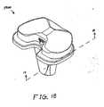
- FIG. 18shows an assembled perspective view of the exemplary sub-assembly of FIG. 13 ;
- FIG. 19shows a cross-sectional view of the exemplary sub-assembly of FIG. 13 along line 19-19 of FIG. 18 ;
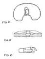
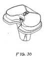
- FIGs. 20-30show views of another exemplary alternative mobile bearing knee prosthesis sub-assembly according to the present invention.
- FIGs. 31-42show views of another exemplary alternative mobile bearing knee prosthesis sub-assembly according to the present invention.
- the terms “medial,” “medially,” and the likemean pertaining to the middle, in or toward the middle, and/or nearer to the middle of the body when standing upright.
- the terms “lateral,” “laterally,” and the likeare used herein as opposed to medial.
- the medial side of the kneeis the side closest to the other knee and the closest sides of the knees are medially facing, whereas the lateral side of the knee is the outside of the knee and is laterally facing.
- the term “superior”means closer to the top of the head and/or farther from the bottom of the feet when standing upright.
- the term “inferior”is used herein as opposed to superior.
- the heartis superior to the stomach and the superior surface of the tongue rests against the palate, whereas the stomach is inferior to the heart and the palate faces inferiorly toward the tongue.
- the terms “anterior,” “anteriorly,” and the likemean nearer the front or facing away from the front of the body when standing upright, as opposed to “posterior,” “posteriorly,” and the like, which mean nearer the back or facing away from the back of the body.
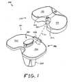
- FIG. 1shows an exploded perspective view of an exemplary mobile bearing knee prosthesis sub-assembly 100 according to the present invention along an explosion/assembly line 110.
- Sub-assembly 100includes an exemplary tibio-femoral insert 120.
- insert 120is configured to emulate a natural tibial plateau (not shown) and natural meniscus (not shown) for a left knee replacement.
- insert 120is made from Ultra High Molecular Weight Polyethylene ("UHMWPE").
- UHMWPEUltra High Molecular Weight Polyethylene
- insert 120may be made from any other suitably strong, smooth, low-wearing biocompatible material(s).
- Insert 120includes a generally anteriorly positioned generally concave superior surface 140 configured to minimize the possibility of impingement of the natural or prosthetic patella (not shown) and the patellar tendon. Insert 120 also includes a generally medially positioned generally concave superior surface 160 and a generally laterally positioned generally concave superior surface 180 which are configured to bear against a generally symmetrical femoral implant (not shown). In the exemplary embodiment, surface 160 and surface 180 have about the same curvature(s). In alternative embodiments, surface 160 and surface 180 may differ in curvature to accommodate a generally asymmetrical femoral implant (not shown).
- Insert 120also includes a generally posteriorly positioned chamfered superior surface 200 configured to minimize soft tissue impingement of a posterior cruciate ligament (not shown). Further, insert 120 defines a generally centrally positioned arcuate cavity or slot 220 that is partially discernable in FIG. 1 . Slot 220 is discussed further below.
- Sub-assembly 100further includes an exemplary tibial implant 300.
- implant 300is configured to anchor into a proximal tibia (not shown) and to support and align insert 120.
- Implant 300is medially-laterally symmetrical such that it can be used effectively in either a right or left knee.
- implant 300is made from a cobalt chrome alloy.
- implant 300may be made from a titanium alloy or any other suitable biocompatible material(s).
- Implant 300includes a stem 320 configured to anchor into the metaphysic and/or intramedullary canal (not shown) of the proximal tibia (not shown).
- Implant 300also includes a tibial plate 340 configured to support and align insert 120.
- Plate 340includes a substantially flat highly polished or otherwise suitably smooth superior surface 360.
- Implant 300also includes a generally centrally positioned stud-like protuberance 380 extending generally superiorly from plate 340.
- protuberance 380is configured to cooperate with slot 220 such that insert 120 is moveable relative to plate 340 about a medially-offset axis 400 (see FIG. 2 , FIG. 4, and FIG. 5 ).
- Implant 300also includes a generally anteriorly positioned bar-like protuberance 420 extending generally superiorly from plate 340.
- protuberance 420is configured to cooperate with insert 120 to limit the motion of insert 120 relative to plate 340 as discussed further below.
- FIG. 2shows a superior plan view of implant 300.
- plate 340includes a medial lobe 460 and a lateral lobe 480 conjoined in a dividing plane 490; surface 360 extends over lobe 460 and lobe 480; lobe 460 and lobe 480 together define a generally posteriorly positioned generally U-shaped space 500; and plane 490 medially-laterally bisects protuberance 380, protuberance 420, and space 500.
- protuberance 380includes a protuberance sidewall 520 (see FIG. 3 ) extending from plate 340 and a boss 540 (see FIG. 3 ) topping off or capping sidewall 520.
- Boss 540(see FIG. 3 ) includes a medial convex arcuate portion 560 and an opposing lateral convex arcuate portion 580 conjoined in plane 490. Portion 560 is eccentric to portion 580, and boss 540 (see FIG. 3 ) is greater in span anteriorly-posteriorly than it is medially-laterally such that boss 540 (see FIG. 3 ) is generally ovularly cross-sectionally shaped.
- portion 560has a curvature radius 600 relative to a laterally-offset axis 620; portion 580 has a curvature radius 640 relative to axis 400; axis 400 is medially disposed from plane 490 by a distance 680; axis 620 is laterally disposed from plane 490 by a distance 700; axis 400 is disposed from axis 620 by a distance 720 that orthogonally passes through plane 490; axis 400 and axis 620 are roughly equidistant from plane 490; radius 600 is roughly equal in magnitude to radius 640; distance 680 is roughly equal in magnitude to distance 700; and portion 560 and portion 580 define a medial-lateral span 740 roughly equaling the scalar sum of radius 600 and radius 640 minus distance 720.
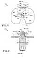
- FIG. 3shows a medial plan view of implant 300.
- Plate 340, protuberance 420, sidewall 520, and boss 540, among other things,are at least partially discernable in FIG. 3 .
- FIG. 4shows a cross-sectional view of implant 300 along line 4-4 of FIG. 3 .
- plane 490medially-laterally bisects sidewall 520; and sidewall 520 includes a medial convex arcuate portion 760 and an opposing lateral convex arcuate portion 780 conjoined in plane 490.
- Portion 760is eccentric to portion 780, and sidewall 520 is greater in span anteriorly-posteriorly than it is medially-laterally such that sidewall 520 is generally ovularly cross-sectionally shaped.
- portion 760has a curvature radius 800 relative to axis 620; portion 780 has a curvature radius 840 relative to axis 400; radius 800 is roughly equal in magnitude to radius 840; and portion 760 and portion 780 define a medial-lateral span 920 roughly equaling the scalar sum of radius 800 and radius 840 minus distance 720.
- radius 800is somewhat smaller than radius 600 (see FIG. 2 ) and radius 840 is likewise smaller than radius 640 (see FIG. 2 ) such that span 740 (see FIG. 2 ) is somewhat greater than span 920 (see also FIG. 5 ).
- Surface 360, protuberance 420, distance 680, and distance 700are also at least partially discernable in FIG. 4 .
- FIG. 5shows a cross-sectional view of implant 300 along line 5-5 of FIG. 2 .
- Axis 400, protuberance 420, plane 490, axis 620, distance 680, distance 700, distance 720, distance 740, and distance 920, among other things,are at least partially discernable in FIG. 5 .
- FIG. 6shows a superior plan view of insert 120.
- insert 120includes a medial lobe 1000 and a lateral lobe 1020 conjoined in a dividing plane 1040.
- Lobe 1000 and lobe 1020together define a generally posteriorly positioned generally U-shaped space 1030 bisected by plane 1040.
- Lobe 1000has anterior-posterior span 1060, while lobe 1020 has anterior-posterior span 1080 that is somewhat smaller than span 1060.
- anterior-posterior asymmetrymay be desirable to enhance modeling of a natural knee (not shown) and/or to otherwise enhance loading/wear characteristics of sub-assembly 100, and/or to reduce the possibility of impingement of the surrounding soft tissues of the knee.
- span 1060 and span 1080may be roughly equal in alternative embodiments.
- Lobe Surface 140, surface 160, surface 180, and surface 200, among other things,are at least partially discernable in FIG. 6 .
- FIG. 7shows a lateral plan view of insert 120.
- insert 120includes a substantially flat smooth inferior surface 1100 and surface 200 is chamfered at an angle 1120 relative to surface 1100.
- angle 1120is at least 30 degrees and not more than 65 degrees.
- lobe 1020(see FIG. 6 ) of insert 120 also includes a generally posteriorly positioned chamfered inferior surface 1140 configured to facilitate generally anterior-to-posterior insertion of insert 120 to implant 300 in a minimally invasive operating space (not shown) along line 110 (see FIG. 1 ).
- Surface 1140is chamfered at an angle 1160 relative to surface 1100.
- lobe 1000see FIG.
- FIG. 6also includes a generally posteriorly positioned chamfered inferior surface 1180 (see FIG. 8 ) configured to facilitate generally anterior-to-posterior insertion of insert 120 to implant 300 in a minimally invasive operating space (not shown) along line 110 (see FIG. 1 ).
- Surface 1180is also chamfered at angle 1160 relative to surface 1100.
- FIG. 8shows an inferior plan view of insert 120.
- slot 220opens generally posteriorly and generally inferiorly and extends generally longitudinally into insert 120 with a central or mean curvature radius 1200 relative to an axis 1220.
- slot 220is configured to receive and slidably engage protuberance 380 (see FIG. 1 ) such that insert 120 is moveable relative to plate 340 about axis 400 (see FIG. 2 , FIG. 4, and FIG. 5 ) and slot 220 is further configured to inferiorly-superiorly retain boss 540 (see FIG. 3 ) such that insert 120 is inferiorly-superiorly retained on plate 340.
- slot 220is arcuately sized to allow about 10-25 degrees of external rotation of insert 120 relative to plate 340 about axis 400.
- the exemplary embodiment axis 1220is medially disposed from plane 1040 by a distance 1240, and radius 1200 is roughly equal in magnitude to distance 1240.
- Distance 1240is roughly equal in magnitude to distance 680 (see FIG. 4 and FIG. 5 ).
- slot 220has a generally medial-side curvature radius 1260 relative to axis 1220 and a generally lateral-side curvature radius 1280 relative to axis 1220.
- Radius 1260is roughly equal in magnitude to distance 720 minus the magnitude of radius 840.
- Radius 1280is roughly equal in magnitude to the magnitude of radius 840 (see FIG. 4 and FIG. 8 ).
- Slot 220also includes a roughly innermost portion or apex portion 1290.
- insert 120also defines a recess 1300 bounded superiorly by a substantially planar smooth ceiling surface 1320 and bounded generally posteriorly and laterally by a wall 1340 that extends generally inferiorly from surface 1320 to surface 1100.
- wall 1340is configured to prevent any more than about 10-25 degrees of internal rotation of insert 120 relative to plate 340 (see FIG. 1 ) by abutting against protuberance 420 (see FIG. 1 ) when the internal rotational limit is reached.
- Space 1030, surface 1140 and surface 1180are also at least partially discernable in FIG. 8 .
- FIG. 9shows a cross-sectional view of insert 120 along line 9-9 of FIG. 6 .
- slot 220includes a tapered portion 1400 opening at surface 1100, extending generally superiorly from surface 1100, and arcing generally posteriorly-anteriorly inward.
- slot 220includes a neck portion 1420 extending generally superiorly from portion 1400 and arcing generally posteriorly-anteriorly inward.
- Portion 1420is configured to slidably engage portion 520 of protuberance 380 (see FIG. 3 ).
- Slot 220also includes a head portion 1440 extending generally superiorly from portion 1420 and arcing generally posteriorly-anteriorly inward.
- Portion 1440is configured to inferior-superiorly retain boss 540 (see FIG. 3 ) without significantly interfering with the slidable engagement between portion 1420 of slot 220 and portion 520 of protuberance 380.
- Surface 160 and surface 180are also at least partially discernable in FIG. 9 .
- FIG. 10shows a cross-sectional view of insert 120 along line 10-10 of FIG. 6 .
- Surface 200, surface 1140, portion 1400, portion 1420, and portion 1440, among other things,are at least partially discernable in FIG. 10 .
- FIG. 11shows an assembled perspective view of sub-assembly 100.
- Insert 120including surface 160 and surface 180
- implant 300including stem 320, plate 340, and surface 360 of plate 340
- FIG. 11shows an assembled perspective view of sub-assembly 100.
- Insert 120including surface 160 and surface 180
- implant 300including stem 320, plate 340, and surface 360 of plate 340
- FIG. 11shows an assembled perspective view of sub-assembly 100.
- Insert 120including surface 160 and surface 180
- implant 300including stem 320, plate 340, and surface 360 of plate 340
- insert 1201 the superior positioning of insert 120 and the sloping of line 110 are exaggerated for clarity of exposition.
- the userprogressively slides slot 220 over protuberance 380 (moving insert 120 generally anteriorly to posteriorly into the joint space) until protuberance 420 clears wall 1340 such that insert 120 snaps into final engagement with tibial plate 340.
- this low-profile, generally anterior to posterior assemblyis well suited for minimally invasive surgeries.
- the userattaches a suitable femoral implant to the distal femur and closes the surgical site as known.
- An alternate embodiment of the disclosed inventionincludes a removable anterior protuberance to facilitate insertion of tibio-femoral insert 120 to implant 300.
- FIG. 12shows a cross-sectional view of sub-assembly 100 along line 12-12 of FIG. 11 .
- axis 1220insert 120
- axis 400implant 300
- surface 360implant 300; see FIG. 1
- slidably supports surface 1100insert 120
- the slidable engagement between protuberance 380 (implant 300) and slot 220 (insert 120)provides freedom of motion (more particularly, external rotational freedom) for insert 120 relative to plate 340 about axis 400 (and axis 1220) as generally indicated by directional line 1460.
- the external rotational freedomis limited to about 10-25 degrees when protuberance 380 abuts portion 1290 of slot 220.
- the engagement between protuberance 380 and slot 220also provides internal rotational freedom for insert 120 relative to plate 340 about axis 400 (and axis 1220) as generally indicated by directional line 1480.
- the internal rotational freedomis not limited by protuberance 380 or slot 220.
- the internal rotational freedom of insert 120 relative to plate 340is limited to about 10-25 degrees when protuberance 420 abuts wall 1340. Further, it is noted that the elongated arcuate engagement between portion 780 (protuberance 380; see FIG.
- Portion 560, portion 760, and surface 1320are at least partially discernable in FIG. 12 .
- FIG. 13shows an exploded perspective view of an exemplary alternative mobile bearing knee prosthesis sub-assembly 1400 according to the present invention along an explosion/assembly line 1410.
- Sub-assembly 1400includes insert 120 (discussed above) and an alternative tibial implant 1600.
- Implant 1600is identical to implant 300 (discussed above) with the exception that protuberance 380 is replaced with an alternative generally centrally positioned stud-like protuberance 1680 extending generally superiorly from plate 340.
- FIG. 14shows a superior plan view of implant 1600. As discernable in FIG. 14 , plane 490 medially-laterally bisects protuberance 1680.
- FIG. 15shows a medial plan view of implant 1600.
- Protuberance 1680is identical to protuberance 380 with the exception that protuberance sidewall 520 is replaced with an alternative protuberance sidewall 1820 extending from plate 340 to boss 540.
- FIG. 16shows a cross-sectional view of implant 1600 along line 16-16 of FIG. 15 .
- plane 490medially-laterally bisects sidewall 1820; and sidewall 1820 includes a generally anteriorly positioned pair of opposing convex arcuate portions 1880, a generally centrally positioned pair of opposing concave arcuate portions 1900, and a generally posteriorly positioned pair of opposing convex arcuate portions 1920.
- Portions 1880have opposing curvature radii 1940 relative to axis 400 and axis 620, respectively (for clarity of depiction, only the radius relative to axis 400 is shown). Radii 1940 are equal in magnitude to radius 800 (discussed above).
- Portions 1900have opposing curvature radii 1960 and 1980 relative to axis 400 and axis 620, respectively. Radii 1960 and 1980 are equal in magnitude to radius 1260 (discussed above). Portions 1920 have opposing curvature radii 2000 relative to axis 400 and axis 620, respectively (for clarity of depiction, only the radius relative to axis 620 is shown). Radii 2000 are equal in magnitude to radius 800 (discussed above). Consequently, it should be appreciated that in the exemplary embodiment protuberance 1680 is generally hour-glass cross-sectionally shaped.
- FIG. 17shows a cross-sectional view of implant 1600 along line 17-17 of FIG. 14 .
- Axis 400 and axis 620are at least partially discernable in FIG. 17 .
- FIG. 18shows an assembled perspective view of sub-assembly 1400; and FIG. 19 shows a cross-sectional view of sub-assembly 1400 along line 19-19 of FIG. 18 .
- Assembly and operation of sub-assembly 1400should be readily appreciable from the drawings and from reference to the assembly and operation of sub-assembly 100 (discussed above).
- FIGs. 20-30show views of another exemplary alternative mobile bearing knee prosthesis sub-assembly 3000 according to the present invention.
- Sub-assembly 3000is made and used in a like manner to sub-assembly 100 with the notable exceptions that protuberance 420 (see FIG. 1 ) and wall 1340 (see FIG. 8 ) are omitted, and internal/external rotational stop features are provided by a generally centrally positioned peg 3020 or, alternatively, a screw extending generally superiorly from an alternative tibial implant 3040 in cooperation with an arcuate inferiorly and posteriorly open channel 3060 into which peg 3020 protrudes. Assembly and operation of sub-assembly 3000 should be readily appreciable from the drawings and from reference to the assembly and operation of sub-assembly 100 (discussed above).
- FIGs. 31-42show views of another exemplary alternative mobile bearing knee prosthesis sub-assembly 4000 according to the present invention.
- Sub-assembly 4000is made and used in a like manner to sub-assembly 100 with the notable exceptions that internal/external rotational stop features are provided by cooperation between an alternative bi-arcuate protuberance 4420 (see FIG. 31 ) and an alternative wall 5340 (see FIG. 38 ) that replace protuberance 420 (see FIG. 1 ) and wall 1340 (see FIG. 8 ), respectively.
- protuberance 4420includes a generally medially positioned arcuate surface 4440 that is concentric to portion 780 of protuberance 340, and includes a generally laterally positioned arcuate surface 4460 that is concentric to portion 760 of protuberance 380 (see FIG. 34 ). Assembly and operation of sub-assembly 4000 should be readily appreciable from the drawings and from reference to the assembly and operation of sub-assembly 100 (discussed above).
Landscapes
- Health & Medical Sciences (AREA)
- Orthopedic Medicine & Surgery (AREA)
- Physical Education & Sports Medicine (AREA)
- Cardiology (AREA)
- Oral & Maxillofacial Surgery (AREA)
- Transplantation (AREA)
- Engineering & Computer Science (AREA)
- Biomedical Technology (AREA)
- Heart & Thoracic Surgery (AREA)
- Vascular Medicine (AREA)
- Life Sciences & Earth Sciences (AREA)
- Animal Behavior & Ethology (AREA)
- General Health & Medical Sciences (AREA)
- Public Health (AREA)
- Veterinary Medicine (AREA)
- Prostheses (AREA)
Description
- The present invention relates generally to the field of orthopaedics, and, more particularly, to a mobile bearing knee prosthesis apparatus.
- Total joint arthroplasty ("joint replacement") is the surgical replacement of a joint with a prosthesis. A typical knee prosthesis has three main components: a femoral implant, a tibial implant, and a tibio-femoral insert. In general, the femoral implant is designed to replace the distal femoral condyles. The femoral implant is typically made from metal. It typically includes a generally concave, facetted (i.e., piecewise planar) inwardly facing surface defining a cavity for receiving a resected distal femur and typically further includes a generally convex outwardly facing surface with medial and lateral rounded portions for emulating the medial and lateral condyles, respectively, and with a valley or depression between the rounded portions for emulating the patella sulcus/trochlear region of the distal femur. In general, the tibial implant is designed to support and align the tibio-femoral insert. The tibial implant is also typically made from metal. It typically includes a substantially planar tray or plate portion ("tibial plate") for supporting the tibio-femoral insert, and an elongated stem extending distally from the tibial plate for anchoring the tibial implant in the metaphysic and/or intramedullary canal of the proximal tibia. In general, the tibio-femoral insert is designed to replace the tibial plateau and the meniscus of the knee. The tibio-femoral insert is typically made of a strong, smooth, low-wearing plastic. It is typically somewhat disk-shaped, and typically includes one or more substantially planar surfaces for bearing on the tibial plate and one or more generally concave surfaces for bearing against the femoral implant. The tibio-femoral insert also typically provides a clearance space ("patellar cutout") for avoiding the natural patella (if saved) or a prosthetic patella (if the natural patella is resurfaced).
- In a traditional knee replacement, a surgeon makes an incision spanning the distal femur, the knee, and the proximal tibia; everts (i.e., flips aside) the patella; separates the distal femur and the proximal tibia from surrounding tissues; and then hyperflexes, distally extends, and/or otherwise distracts the proximal tibia from the distal femur to enlarge the operating space. Next, the surgeon uses various resection guides and saws to prepare the proximal tibia and the distal femur for receiving the replacement prosthesis. A resection guide is a specialized jig or template configured to provide a desired cutting angle for a saw blade or other resection tool. After completing the necessary resections, the surgeon may apply cement to the distal femur and/or to the proximal tibia to ultimately help hold the femoral implant and/or tibial implant, respectively, in place. Alternatively, cementless fixation may be desired. Finally, the surgeon secures the tibial implant and the femoral implant to the proximal tibia and the distal femur, respectively, secures the tibio-femoral insert to the tibial implant, returns the patella or resurfaces it with a prosthetic component, and closes the incision.
- In a "fixed bearing" knee prosthesis, the tibio-femoral insert is rotationally fixed relative to the tibial plate; whereas, in a "mobile bearing" knee prosthesis the tibio-femoral insert can pivot relative to the tibial plate to allow proper alignment with the femoral component, reduce stresses at the bone - prosthesis interface, and promote load sharing with surrounding soft tissues. Historically, the pivotal axis of the tibio-femoral insert in mobile bearing designs has been centered between medial and lateral portions of the tibial plate; the tibio-femoral insert has had symmetrical medial and lateral portions; and the patellar cutout has been centered between the medial and lateral portions of the tibio-femoral insert. However, the natural human knee has a pivotal axis that is actually medially offset (i.e., extends only into the medial compartment of the proximal tibia as opposed to being centered between the medial and lateral compartments); the anterior-posterior dimension of the lateral compartment of the natural tibial plateau is actually smaller than that of the medial compartment. Additionally, the risk of bearing dislocation or "spinout" may be undesirably high for some mobile bearing designs that do not incorporate stops to limit the rotation of the tibio-femoral insert; and the posterior cruciate ligament ("PCL"), when saved, may be undesirably impinged by posterior surfaces of some mobile bearing designs.
- Moreover, minimally invasive surgical techniques are becoming increasingly popular. Minimally invasive surgeries generally involve, among other things, considerably smaller incisions and tighter working spaces than historical techniques in efforts to reduce patient traumas and accelerate post-operative recoveries. As minimally invasive surgery generally reduces the size of the surgical site, it also generally reduces the amount of space available for inserting, aligning, and securing the prosthetics. Some mobile bearing designs have a tibio-femoral insert that must be installed from above the tibial plate. The substantial exposures and separations of the distal femur and the proximal tibia required for some such "overhead" tibio-femoral insert installations are becoming increasingly incompatible with the space constraints of minimally invasive surgery.
EP 0 634 155 A2 discloses a mobile bearing knee prosthesis apparatus according to the preamble ofclaim 1.EP 0 634 156 A2 andUS 5,928,286 A each disclose a knee prosthesis apparatus with a tibio-femoral insert having a curved slot to receive a circular protuberance of a tibial plate.- To solve the problems outlined above the present invention provides a mobile bearing knee prosthesis apparatus with the features recited by
claim 1.
The above-noted features and advantages of the present invention, as well as additional features and advantages, will be readily apparent to those skilled in the art upon reference to the following detailed description and the accompanying drawings, which include a disclosure of the best mode of making and using the invention presently contemplated. FIG. 1 shows an exploded perspective view of an exemplary mobile bearing knee prosthesis sub-assembly according to the present invention along an explosion/assembly line;FIG. 2 shows a superior plan view of the exemplary tibial implant of the exemplary sub-assembly ofFIG. 1 ;FIG. 3 shows a medial plan view of the exemplary tibial implant of the exemplary sub-assembly ofFIG. 1 ;FIG. 4 shows a cross-sectional view of the exemplary tibial implant of the exemplary sub-assembly ofFIG. 1 along line 4-4 ofFIG. 3 ;FIG. 5 shows a cross-sectional view of the exemplary tibial implant of the exemplary sub-assembly ofFIG. 1 along line 5-5 ofFIG. 2 ;FIG. 6 shows a superior plan view of the exemplary tibio-femoral insert of the exemplary sub-assembly ofFIG. 1 ;FIG. 7 shows a lateral plan view of the exemplary tibio-femoral insert of the exemplary sub-assembly ofFIG. 1 ;FIG. 8 shows an inferior plan view of the exemplary tibio-femoral insert of the exemplary sub-assembly ofFIG. 1 ;FIG. 9 shows a cross-sectional view of the exemplary tibio-femoral insert of the exemplary sub-assembly ofFIG. 1 along line 9-9 ofFIG. 6 ;FIG. 10 shows a cross-sectional view of the exemplary tibio-femoral insert of the exemplary sub-assembly ofFIG. 1 along line 10-10 ofFIG. 6 ;FIG. 11 shows an assembled perspective view of the exemplary sub-assembly ofFIG. 1 ;FIG. 12 shows a cross-sectional view of the exemplary sub-assembly ofFIG. 1 along line 12-12 ofFIG. 11 ;FIG. 13 shows an exploded perspective view of an exemplary alternative mobile bearing knee prosthesis sub-assembly according to the present invention along an explosion/assembly line;FIG. 14 shows a superior plan view of the exemplary tibial implant of the exemplary sub-assembly ofFIG. 13 ;FIG. 15 shows a medial plan view of the exemplary tibial implant of the exemplary sub-assembly ofFIG. 13 ;FIG. 16 shows a cross-sectional view of the exemplary tibial implant of the exemplary sub-assembly ofFIG. 13 along line 16-16 ofFIG. 15 ;FIG. 17 shows a cross-sectional view of the exemplary tibial implant of the exemplary sub-assembly ofFIG. 13 along line 17-17 ofFIG. 14 ;FIG. 18 shows an assembled perspective view of the exemplary sub-assembly ofFIG. 13 ;FIG. 19 shows a cross-sectional view of the exemplary sub-assembly ofFIG. 13 along line 19-19 ofFIG. 18 ; andFIGs. 20-30 show views of another exemplary alternative mobile bearing knee prosthesis sub-assembly according to the present invention; andFIGs. 31-42 show views of another exemplary alternative mobile bearing knee prosthesis sub-assembly according to the present invention.- Like reference numerals refer to like parts throughout the following description and the accompanying drawings. As used herein, the terms "medial," "medially," and the like mean pertaining to the middle, in or toward the middle, and/or nearer to the middle of the body when standing upright. Conversely, the terms "lateral," "laterally," and the like are used herein as opposed to medial. For example, the medial side of the knee is the side closest to the other knee and the closest sides of the knees are medially facing, whereas the lateral side of the knee is the outside of the knee and is laterally facing. Further, as used herein the term "superior" means closer to the top of the head and/or farther from the bottom of the feet when standing upright. Conversely, the term "inferior" is used herein as opposed to superior. For example, the heart is superior to the stomach and the superior surface of the tongue rests against the palate, whereas the stomach is inferior to the heart and the palate faces inferiorly toward the tongue. Additionally, as used herein the terms "anterior," "anteriorly," and the like mean nearer the front or facing away from the front of the body when standing upright, as opposed to "posterior," "posteriorly," and the like, which mean nearer the back or facing away from the back of the body.
- It is noted, however, that many of the particularly directional and/or positional terms and inflections thereof are used herein merely for clarity of exposition, and at times they may be somewhat arbitrary or interchangeable as known in the art. For example, although the present invention is described herein relative to exemplary left knee embodiments, it should be appreciated that in many cases corresponding right knee embodiments may be made by simply exchanging "medial" and "lateral" indications where appropriate (i.e., medial-lateral mirroring).
FIG. 1 shows an exploded perspective view of an exemplary mobile bearingknee prosthesis sub-assembly 100 according to the present invention along an explosion/assembly line 110.Sub-assembly 100 includes an exemplary tibio-femoral insert 120. Among other things, insert 120 is configured to emulate a natural tibial plateau (not shown) and natural meniscus (not shown) for a left knee replacement. In the exemplary embodiment, insert 120 is made from Ultra High Molecular Weight Polyethylene ("UHMWPE"). In alternative embodiments, insert 120 may be made from any other suitably strong, smooth, low-wearing biocompatible material(s).Insert 120 includes a generally anteriorly positioned generally concavesuperior surface 140 configured to minimize the possibility of impingement of the natural or prosthetic patella (not shown) and the patellar tendon.Insert 120 also includes a generally medially positioned generally concavesuperior surface 160 and a generally laterally positioned generally concavesuperior surface 180 which are configured to bear against a generally symmetrical femoral implant (not shown). In the exemplary embodiment,surface 160 andsurface 180 have about the same curvature(s). In alternative embodiments,surface 160 andsurface 180 may differ in curvature to accommodate a generally asymmetrical femoral implant (not shown).Insert 120 also includes a generally posteriorly positioned chamferedsuperior surface 200 configured to minimize soft tissue impingement of a posterior cruciate ligament (not shown). Further, insert 120 defines a generally centrally positioned arcuate cavity or slot 220 that is partially discernable inFIG. 1 .Slot 220 is discussed further below.Sub-assembly 100 further includes anexemplary tibial implant 300. Among other things,implant 300 is configured to anchor into a proximal tibia (not shown) and to support and aligninsert 120.Implant 300 is medially-laterally symmetrical such that it can be used effectively in either a right or left knee. In the exemplary embodiment,implant 300 is made from a cobalt chrome alloy. In alternative embodiments,implant 300 may be made from a titanium alloy or any other suitable biocompatible material(s).Implant 300 includes astem 320 configured to anchor into the metaphysic and/or intramedullary canal (not shown) of the proximal tibia (not shown).Implant 300 also includes atibial plate 340 configured to support and aligninsert 120.Plate 340 includes a substantially flat highly polished or otherwise suitably smoothsuperior surface 360.Implant 300 also includes a generally centrally positioned stud-like protuberance 380 extending generally superiorly fromplate 340. Among other things,protuberance 380 is configured to cooperate withslot 220 such thatinsert 120 is moveable relative to plate 340 about a medially-offset axis 400 (seeFIG. 2 ,FIG. 4, and FIG. 5 ).Implant 300 also includes a generally anteriorly positioned bar-like protuberance 420 extending generally superiorly fromplate 340. Among other things,protuberance 420 is configured to cooperate withinsert 120 to limit the motion ofinsert 120 relative to plate 340 as discussed further below.FIG. 2 shows a superior plan view ofimplant 300. As discernable inFIG. 2 :plate 340 includes amedial lobe 460 and alateral lobe 480 conjoined in a dividingplane 490;surface 360 extends overlobe 460 andlobe 480;lobe 460 andlobe 480 together define a generally posteriorly positioned generallyU-shaped space 500; andplane 490 medially-laterally bisectsprotuberance 380,protuberance 420, andspace 500. Further,protuberance 380 includes a protuberance sidewall 520 (seeFIG. 3 ) extending fromplate 340 and a boss 540 (seeFIG. 3 ) topping off or cappingsidewall 520. Boss 540 (seeFIG. 3 ) includes a medial convexarcuate portion 560 and an opposing lateral convexarcuate portion 580 conjoined inplane 490.Portion 560 is eccentric toportion 580, and boss 540 (seeFIG. 3 ) is greater in span anteriorly-posteriorly than it is medially-laterally such that boss 540 (seeFIG. 3 ) is generally ovularly cross-sectionally shaped. More particularly:portion 560 has acurvature radius 600 relative to a laterally-offsetaxis 620;portion 580 has acurvature radius 640 relative toaxis 400;axis 400 is medially disposed fromplane 490 by adistance 680;axis 620 is laterally disposed fromplane 490 by adistance 700;axis 400 is disposed fromaxis 620 by adistance 720 that orthogonally passes throughplane 490;axis 400 andaxis 620 are roughly equidistant fromplane 490;radius 600 is roughly equal in magnitude toradius 640;distance 680 is roughly equal in magnitude to distance 700; andportion 560 andportion 580 define a medial-lateral span 740 roughly equaling the scalar sum ofradius 600 andradius 640minus distance 720.FIG. 3 shows a medial plan view ofimplant 300.Plate 340,protuberance 420,sidewall 520, andboss 540, among other things, are at least partially discernable inFIG. 3 .FIG. 4 shows a cross-sectional view ofimplant 300 along line 4-4 ofFIG. 3 . As discernable inFIG. 4 :plane 490 medially-laterally bisectssidewall 520; andsidewall 520 includes a medial convexarcuate portion 760 and an opposing lateral convexarcuate portion 780 conjoined inplane 490.Portion 760 is eccentric toportion 780, andsidewall 520 is greater in span anteriorly-posteriorly than it is medially-laterally such thatsidewall 520 is generally ovularly cross-sectionally shaped. More particularly:portion 760 has acurvature radius 800 relative toaxis 620;portion 780 has acurvature radius 840 relative toaxis 400;radius 800 is roughly equal in magnitude toradius 840; andportion 760 andportion 780 define a medial-lateral span 920 roughly equaling the scalar sum ofradius 800 andradius 840minus distance 720. Additionally,radius 800 is somewhat smaller than radius 600 (seeFIG. 2 ) andradius 840 is likewise smaller than radius 640 (seeFIG. 2 ) such that span 740 (seeFIG. 2 ) is somewhat greater than span 920 (see alsoFIG. 5 ).Surface 360,protuberance 420,distance 680, anddistance 700, among other things, are also at least partially discernable inFIG. 4 .FIG. 5 shows a cross-sectional view ofimplant 300 along line 5-5 ofFIG. 2 .Axis 400,protuberance 420,plane 490,axis 620,distance 680,distance 700,distance 720,distance 740, anddistance 920, among other things, are at least partially discernable inFIG. 5 .FIG. 6 shows a superior plan view ofinsert 120. As discernable inFIG. 6 , insert 120 includes amedial lobe 1000 and a lateral lobe 1020 conjoined in a dividingplane 1040.Lobe 1000 and lobe 1020 together define a generally posteriorly positioned generallyU-shaped space 1030 bisected byplane 1040.Lobe 1000 has anterior-posterior span 1060, while lobe 1020 has anterior-posterior span 1080 that is somewhat smaller thanspan 1060. In some cases, such anterior-posterior asymmetry may be desirable to enhance modeling of a natural knee (not shown) and/or to otherwise enhance loading/wear characteristics ofsub-assembly 100, and/or to reduce the possibility of impingement of the surrounding soft tissues of the knee. However, it is noted thatspan 1060 andspan 1080 may be roughly equal in alternative embodiments.Lobe Surface 140,surface 160,surface 180, andsurface 200, among other things, are at least partially discernable inFIG. 6 .FIG. 7 shows a lateral plan view ofinsert 120. As discernable inFIG. 7 , insert 120 includes a substantially flat smoothinferior surface 1100 andsurface 200 is chamfered at anangle 1120 relative tosurface 1100. In the exemplary embodiment,angle 1120 is at least 30 degrees and not more than 65 degrees. Further, lobe 1020 (seeFIG. 6 ) ofinsert 120 also includes a generally posteriorly positioned chamferedinferior surface 1140 configured to facilitate generally anterior-to-posterior insertion ofinsert 120 to implant 300 in a minimally invasive operating space (not shown) along line 110 (seeFIG. 1 ).Surface 1140 is chamfered at anangle 1160 relative tosurface 1100. Similarly, lobe 1000 (seeFIG. 6 ) also includes a generally posteriorly positioned chamfered inferior surface 1180 (seeFIG. 8 ) configured to facilitate generally anterior-to-posterior insertion ofinsert 120 to implant 300 in a minimally invasive operating space (not shown) along line 110 (seeFIG. 1 ).Surface 1180 is also chamfered atangle 1160 relative tosurface 1100.FIG. 8 shows an inferior plan view ofinsert 120. As at least partially discemable inFIG. 8 ,slot 220 opens generally posteriorly and generally inferiorly and extends generally longitudinally intoinsert 120 with a central ormean curvature radius 1200 relative to anaxis 1220. Among other things,slot 220 is configured to receive and slidably engage protuberance 380 (seeFIG. 1 ) such thatinsert 120 is moveable relative to plate 340 about axis 400 (seeFIG. 2 ,FIG. 4, and FIG. 5 ) andslot 220 is further configured to inferiorly-superiorly retain boss 540 (seeFIG. 3 ) such thatinsert 120 is inferiorly-superiorly retained onplate 340. In the exemplary embodiment,slot 220 is arcuately sized to allow about 10-25 degrees of external rotation ofinsert 120 relative to plate 340 aboutaxis 400. Theexemplary embodiment axis 1220 is medially disposed fromplane 1040 by a distance 1240, andradius 1200 is roughly equal in magnitude to distance 1240. Distance 1240 is roughly equal in magnitude to distance 680 (seeFIG. 4 and FIG. 5 ). Further,slot 220 has a generally medial-side curvature radius 1260 relative toaxis 1220 and a generally lateral-side curvature radius 1280 relative toaxis 1220.Radius 1260 is roughly equal in magnitude to distance 720 minus the magnitude ofradius 840.Radius 1280 is roughly equal in magnitude to the magnitude of radius 840 (seeFIG. 4 andFIG. 8 ). Slot 220 also includes a roughly innermost portion orapex portion 1290.- As further discernable in
FIG. 8 , insert 120 also defines arecess 1300 bounded superiorly by a substantially planarsmooth ceiling surface 1320 and bounded generally posteriorly and laterally by awall 1340 that extends generally inferiorly fromsurface 1320 tosurface 1100. In the exemplary embodiment,wall 1340 is configured to prevent any more than about 10-25 degrees of internal rotation ofinsert 120 relative to plate 340 (seeFIG. 1 ) by abutting against protuberance 420 (seeFIG. 1 ) when the internal rotational limit is reached.Space 1030,surface 1140 andsurface 1180, among other things, are also at least partially discernable inFIG. 8 . FIG. 9 shows a cross-sectional view ofinsert 120 along line 9-9 ofFIG. 6 . As at least partially discernable inFIG. 9 ,slot 220 includes a taperedportion 1400 opening atsurface 1100, extending generally superiorly fromsurface 1100, and arcing generally posteriorly-anteriorly inward. Further,slot 220 includes aneck portion 1420 extending generally superiorly fromportion 1400 and arcing generally posteriorly-anteriorly inward.Portion 1420 is configured to slidably engageportion 520 of protuberance 380 (seeFIG. 3 ). Slot 220 also includes ahead portion 1440 extending generally superiorly fromportion 1420 and arcing generally posteriorly-anteriorly inward.Portion 1440 is configured to inferior-superiorly retain boss 540 (seeFIG. 3 ) without significantly interfering with the slidable engagement betweenportion 1420 ofslot 220 andportion 520 ofprotuberance 380.Surface 160 andsurface 180, among other things, are also at least partially discernable inFIG. 9 .FIG. 10 shows a cross-sectional view ofinsert 120 along line 10-10 ofFIG. 6 .Surface 200,surface 1140,portion 1400,portion 1420, andportion 1440, among other things, are at least partially discernable inFIG. 10 .FIG. 11 shows an assembled perspective view ofsub-assembly 100. Insert 120 (includingsurface 160 and surface 180) and implant 300 (includingstem 320,plate 340, andsurface 360 of plate 340), among other things, are at least partially discernable inFIG. 11 . In assembly ofsub-assembly 100, a surgeon or other user suitably opens a knee joint in a known manner. After properly resecting the affected proximal tibia, the user anchors stem 320 ofimplant 300 into the proximal tibia as known. After anchoringimplant 300, the user positions insert 120 generally anteriorly to and slightly superiorly to plate 340 (seeFIG. 1 ), and tips insert 120 to generally align it with line 110 (seeFIG. 1 ). It is noted that inFIG. 1 the superior positioning ofinsert 120 and the sloping ofline 110 are exaggerated for clarity of exposition. To complete the assembly, the user progressively slidesslot 220 over protuberance 380 (movinginsert 120 generally anteriorly to posteriorly into the joint space) untilprotuberance 420 clearswall 1340 such thatinsert 120 snaps into final engagement withtibial plate 340. It should be appreciated that this low-profile, generally anterior to posterior assembly is well suited for minimally invasive surgeries. Afterinsert 120 is snapped into engagement withplate 340, the user attaches a suitable femoral implant to the distal femur and closes the surgical site as known. An alternate embodiment of the disclosed invention includes a removable anterior protuberance to facilitate insertion of tibio-femoral insert 120 toimplant 300.FIG. 12 shows a cross-sectional view ofsub-assembly 100 along line 12-12 ofFIG. 11 . In operation ofexemplary sub-assembly 100, axis 1220 (insert 120) remains roughly axially aligned with axis 400 (implant 300), surface 360 (implant 300; seeFIG. 1 ) slidably supports surface 1100 (insert 120), and the slidable engagement between protuberance 380 (implant 300) and slot 220 (insert 120) provides freedom of motion (more particularly, external rotational freedom) forinsert 120 relative to plate 340 about axis 400 (and axis 1220) as generally indicated bydirectional line 1460. The external rotational freedom is limited to about 10-25 degrees whenprotuberance 380 abutsportion 1290 ofslot 220. The engagement betweenprotuberance 380 and slot 220 also provides internal rotational freedom forinsert 120 relative to plate 340 about axis 400 (and axis 1220) as generally indicated bydirectional line 1480. However, the internal rotational freedom is not limited byprotuberance 380 orslot 220. The internal rotational freedom ofinsert 120 relative to plate 340 is limited to about 10-25 degrees whenprotuberance 420 abutswall 1340. Further, it is noted that the elongated arcuate engagement between portion 780 (protuberance 380; seeFIG. 4 ) andslot 220 with the roughly equal curvature radii increases contact surface area betweeninsert 120 andprotuberance 380 and, thus, provides more resistance to axial micro-motion and anterior-posterior shear forces.Portion 560,portion 760, andsurface 1320, among other things, are at least partially discernable inFIG. 12 .FIG. 13 shows an exploded perspective view of an exemplary alternative mobile bearingknee prosthesis sub-assembly 1400 according to the present invention along an explosion/assembly line 1410.Sub-assembly 1400 includes insert 120 (discussed above) and analternative tibial implant 1600.Implant 1600 is identical to implant 300 (discussed above) with the exception that protuberance 380 is replaced with an alternative generally centrally positioned stud-like protuberance 1680 extending generally superiorly fromplate 340.FIG. 14 shows a superior plan view ofimplant 1600. As discernable inFIG. 14 ,plane 490 medially-laterally bisectsprotuberance 1680.FIG. 15 shows a medial plan view ofimplant 1600.Protuberance 1680 is identical toprotuberance 380 with the exception that protuberancesidewall 520 is replaced with analternative protuberance sidewall 1820 extending fromplate 340 toboss 540.FIG. 16 shows a cross-sectional view ofimplant 1600 along line 16-16 ofFIG. 15 . As discernable inFIG. 16 :plane 490 medially-laterally bisectssidewall 1820; andsidewall 1820 includes a generally anteriorly positioned pair of opposing convexarcuate portions 1880, a generally centrally positioned pair of opposing concavearcuate portions 1900, and a generally posteriorly positioned pair of opposing convexarcuate portions 1920.Portions 1880 have opposingcurvature radii 1940 relative toaxis 400 andaxis 620, respectively (for clarity of depiction, only the radius relative toaxis 400 is shown).Radii 1940 are equal in magnitude to radius 800 (discussed above).Portions 1900 have opposingcurvature radii axis 400 andaxis 620, respectively.Radii Portions 1920 have opposingcurvature radii 2000 relative toaxis 400 andaxis 620, respectively (for clarity of depiction, only the radius relative toaxis 620 is shown).Radii 2000 are equal in magnitude to radius 800 (discussed above). Consequently, it should be appreciated that in theexemplary embodiment protuberance 1680 is generally hour-glass cross-sectionally shaped.FIG. 17 shows a cross-sectional view ofimplant 1600 along line 17-17 ofFIG. 14 .Axis 400 andaxis 620, among other things, are at least partially discernable inFIG. 17 .FIG. 18 shows an assembled perspective view ofsub-assembly 1400; andFIG. 19 shows a cross-sectional view ofsub-assembly 1400 along line 19-19 ofFIG. 18 . Assembly and operation of sub-assembly 1400 should be readily appreciable from the drawings and from reference to the assembly and operation of sub-assembly 100 (discussed above).FIGs. 20-30 show views of another exemplary alternative mobile bearingknee prosthesis sub-assembly 3000 according to the present invention.Sub-assembly 3000 is made and used in a like manner to sub-assembly 100 with the notable exceptions that protuberance 420 (seeFIG. 1 ) and wall 1340 (seeFIG. 8 ) are omitted, and internal/external rotational stop features are provided by a generally centrally positionedpeg 3020 or, alternatively, a screw extending generally superiorly from analternative tibial implant 3040 in cooperation with an arcuate inferiorly and posteriorly open channel 3060 into which peg 3020 protrudes. Assembly and operation of sub-assembly 3000 should be readily appreciable from the drawings and from reference to the assembly and operation of sub-assembly 100 (discussed above).FIGs. 31-42 show views of another exemplary alternative mobile bearingknee prosthesis sub-assembly 4000 according to the present invention.Sub-assembly 4000 is made and used in a like manner to sub-assembly 100 with the notable exceptions that internal/external rotational stop features are provided by cooperation between an alternative bi-arcuate protuberance 4420 (seeFIG. 31 ) and an alternative wall 5340 (seeFIG. 38 ) that replace protuberance 420 (seeFIG. 1 ) and wall 1340 (seeFIG. 8 ), respectively. Further, it is noted thatprotuberance 4420 includes a generally medially positionedarcuate surface 4440 that is concentric toportion 780 ofprotuberance 340, and includes a generally laterally positionedarcuate surface 4460 that is concentric toportion 760 of protuberance 380 (seeFIG. 34 ). Assembly and operation of sub-assembly 4000 should be readily appreciable from the drawings and from reference to the assembly and operation of sub-assembly 100 (discussed above).- The foregoing description of the invention is illustrative only, and is not intended to limit the scope of the invention to the precise terms set forth. Further, although the invention has been described in detail with reference to certain illustrative embodiments, variations and modifications exist within the scope of the invention as described and defined in the following claims.
Claims (15)
- A mobile bearing knee prosthesis apparatus, comprising:a tibial plate (340) including a medial lobe and a lateral lobe conjoined in a dividing plane;a tibio-femoral insert (120); anda stud-like protuberance (380) extending from the tibial plate (340) into the tibio-femoral insert, the stud-like protuberance (380) including a protuberance sidewall (520) positioned in the tibio-femoral insert (120), the protuberance sidewall (520) being bisected by the dividing plane (490) and including a pair of opposing eccentric convex arcuate portion (760, 780),wherein the pair of opposing eccentric convex arcuate portions (780, 760) includes a first convex arcuate portion (780) having a curvature radius (840) and a center of curvature which lies on a medially disposed axis (400), the pair of opposing eccentric convex arcuate portions (780, 760) further includes a second convex arcuate portion (760) having a curvature radius and a center of curvature which lies on an axis (620) laterally disposed from the dividing plane (490), and the curvature radius (840) of the first convex arcuate portion (780) is roughly equal in magnitude to the curvature radius (800) of the second convex arcuate portion (760);wherein the tibio-femoral insert (120) is moveable relative to the tibial plate (340) about said axis (400) medially disposed from the dividing plane; andwherein the tibio-femoral insert defines a slot (220) and the protuberance sidewall (520) is positioned in the slot (220);characterized in thatsaid slot (220) has a generally lateral-side curvature radius (1280) roughly equal to the curvature radius (840) of the first convex arcuate portion (780) of the protuberance sidewall (520).
- The apparatus of claim 1, wherein the medially disposed axis (400) is disposed from the dividing plane (490, 1040) by a first distance (400), and the slot (220) has a mean curvature (1200) radius roughly equal in magnitude to the first distance (700).
- The apparatus of claim 2, wherein the slot (220) has a generally medial-side curvature radius (1260) roughly equal to a distance (720) between the laterally disposed axis (620) and the medially disposed axis (400) minus the curvature radius (840) of the first convex arcuate portion (780) of the protuberance sidewall (520).
- The apparatus of claim 3, wherein the protuberance sidewall (520) is generally ovularly cross-sectionally shaped.
- The apparatus of claim 1, wherein the protuberance sidewall (520) further includes a pair of opposing eccentric concave arcuate portions (1900), the pair of opposing eccentric concave arcuate portions (1900) includes a first concave arcuate portion (1900) having a curvature radius (1960) and a center of curvature which lies on the medially disposed axis (400), the pair of opposing eccentric concave arcuate portions (1900) further includes a second convex arcuate portion (1900) having a curvature radius (1980) and a center of curvature which lies on the laterally disposed axis (620), and the curvature radius (1960) of the first concave arcuate portion (1900) is roughly equal in magnitude to the curvature radius (1980) of the second concave arcuate portion (1900).
- The apparatus of claim 5, wherein the medially disposed axis (400) is disposed from the dividing plane (490) by a first distance (680), and the slot (220) has a mean curvature radius (1200) roughly equal in magnitude to the first distance (680).
- The apparatus of claim 6, wherein the slot (220) has a generally medial-side curvature radius (1260) roughly equal to a distance (720) between the laterally disposed axis (620) and the medially disposed axis (400) minus the curvature radius (840) of the first convex arcuate portion (780) of the protuberance sidewall (520).
- The apparatus of claim 7, wherein the protuberance sidewall (520) is generally hour-glass cross-sectionally shaped.
- The apparatus of claim 1, further comprising:a bar-like protuberance (420, 4420) extending from the tibial plate (340);wherein the tibio-femoral insert (120) defines a recess (1300, 5340) and the bar-like protuberance (420) is positioned in the recess (1300, 5340).
- The apparatus of claim 9, wherein the bar-like protuberance (420, 4420) is removable from the tibial plate (340).
- The apparatus of claim 9, wherein the bar-like protuberance (420, 4420) is bisected by the dividing plane (490, 1040) and includes a plurality of arcuate surfaces (4440, 4460).
- The apparatus of claim 1, further comprising:bar-like protuberance (4420) extending from the tibial plate (340);wherein the bar-like protuberance (4420) includes a generally medially positioned arcuate surface (4440) concentric to the first convex arcuate portion (780) of the protuberance sidewall (520), the bar-like protuberance (4420) further includes a generally laterally positioned arcuate surface (4460) concentric to the second convex arcuate portion (760) of the protuberance sidewall (520), the tibio-femoral insert (120) defines a recess (5340), and the bar-like protuberance (4420) is positioned in the recess (5340).
- The apparatus of claim 1, further comprising:means, integrated with at least one of the tibial plate (340) and the tibio-femoral insert (120), for limiting motion of the tibio-femoral insert (120) relative to the tibial plate (340).
- The apparatus of claim 1 wherein the tibio-femoral insert (120) includes a generally posteriorly positioned chamfered superior surface (200) and defines a generally posteriorly positioned generally U-shaped space bounded at least in part by the chamfered surface (200).
- The apparatus of claim 14, wherein the chamfered surface (200) is chamfered at an angle between 30 degrees and 65 degrees, inclusive.
Applications Claiming Priority (2)
| Application Number | Priority Date | Filing Date | Title |
|---|---|---|---|
| US55210404P | 2004-03-09 | 2004-03-09 | |
| US552104P | 2004-03-09 |
Publications (3)
| Publication Number | Publication Date |
|---|---|
| EP1574185A2 EP1574185A2 (en) | 2005-09-14 |
| EP1574185A3 EP1574185A3 (en) | 2005-11-16 |
| EP1574185B1true EP1574185B1 (en) | 2012-05-23 |
Family
ID=34826266
Family Applications (1)
| Application Number | Title | Priority Date | Filing Date |
|---|---|---|---|
| EP05005021ANot-in-forceEP1574185B1 (en) | 2004-03-09 | 2005-03-08 | Tibial knee component with a mobile bearing |
Country Status (2)
| Country | Link |
|---|---|
| US (1) | US8137407B2 (en) |
| EP (1) | EP1574185B1 (en) |
Families Citing this family (116)
| Publication number | Priority date | Publication date | Assignee | Title |
|---|---|---|---|---|
| US6558426B1 (en) | 2000-11-28 | 2003-05-06 | Medidea, Llc | Multiple-cam, posterior-stabilized knee prosthesis |
| US8388624B2 (en) | 2003-02-24 | 2013-03-05 | Arthrosurface Incorporated | Trochlear resurfacing system and method |
| US7905904B2 (en) | 2006-02-03 | 2011-03-15 | Biomet Sports Medicine, Llc | Soft tissue repair device and associated methods |
| US9017381B2 (en) | 2007-04-10 | 2015-04-28 | Biomet Sports Medicine, Llc | Adjustable knotless loops |
| US8298262B2 (en) | 2006-02-03 | 2012-10-30 | Biomet Sports Medicine, Llc | Method for tissue fixation |
| US8088130B2 (en) | 2006-02-03 | 2012-01-03 | Biomet Sports Medicine, Llc | Method and apparatus for coupling soft tissue to a bone |
| US8303604B2 (en) | 2004-11-05 | 2012-11-06 | Biomet Sports Medicine, Llc | Soft tissue repair device and method |
| US7749250B2 (en) | 2006-02-03 | 2010-07-06 | Biomet Sports Medicine, Llc | Soft tissue repair assembly and associated method |
| US8128658B2 (en) | 2004-11-05 | 2012-03-06 | Biomet Sports Medicine, Llc | Method and apparatus for coupling soft tissue to bone |
| US7658751B2 (en) | 2006-09-29 | 2010-02-09 | Biomet Sports Medicine, Llc | Method for implanting soft tissue |
| US7909851B2 (en) | 2006-02-03 | 2011-03-22 | Biomet Sports Medicine, Llc | Soft tissue repair device and associated methods |
| US8118836B2 (en) | 2004-11-05 | 2012-02-21 | Biomet Sports Medicine, Llc | Method and apparatus for coupling soft tissue to a bone |
| US8137382B2 (en) | 2004-11-05 | 2012-03-20 | Biomet Sports Medicine, Llc | Method and apparatus for coupling anatomical features |
| US8361113B2 (en) | 2006-02-03 | 2013-01-29 | Biomet Sports Medicine, Llc | Method and apparatus for coupling soft tissue to a bone |
| US7695519B2 (en)* | 2005-07-08 | 2010-04-13 | Howmedica Osteonics Corp. | Modular tibial baseplate |
| US11311287B2 (en) | 2006-02-03 | 2022-04-26 | Biomet Sports Medicine, Llc | Method for tissue fixation |
| US10517587B2 (en) | 2006-02-03 | 2019-12-31 | Biomet Sports Medicine, Llc | Method and apparatus for forming a self-locking adjustable loop |
| US8801783B2 (en) | 2006-09-29 | 2014-08-12 | Biomet Sports Medicine, Llc | Prosthetic ligament system for knee joint |
| US8597327B2 (en) | 2006-02-03 | 2013-12-03 | Biomet Manufacturing, Llc | Method and apparatus for sternal closure |
| US11259792B2 (en) | 2006-02-03 | 2022-03-01 | Biomet Sports Medicine, Llc | Method and apparatus for coupling anatomical features |
| US9078644B2 (en) | 2006-09-29 | 2015-07-14 | Biomet Sports Medicine, Llc | Fracture fixation device |
| US8562647B2 (en) | 2006-09-29 | 2013-10-22 | Biomet Sports Medicine, Llc | Method and apparatus for securing soft tissue to bone |
| US8652171B2 (en) | 2006-02-03 | 2014-02-18 | Biomet Sports Medicine, Llc | Method and apparatus for soft tissue fixation |
| US8968364B2 (en) | 2006-02-03 | 2015-03-03 | Biomet Sports Medicine, Llc | Method and apparatus for fixation of an ACL graft |
| US8562645B2 (en) | 2006-09-29 | 2013-10-22 | Biomet Sports Medicine, Llc | Method and apparatus for forming a self-locking adjustable loop |
| US9468433B2 (en) | 2006-02-03 | 2016-10-18 | Biomet Sports Medicine, Llc | Method and apparatus for forming a self-locking adjustable loop |
| US7771484B2 (en)* | 2006-02-28 | 2010-08-10 | Howmedica Osteonics Corp. | Modular tibial implant |
| EP1996122B1 (en)* | 2006-03-21 | 2012-11-21 | DePuy (Ireland) | Moment induced total arthroplasty prosthetic |
| US11259794B2 (en) | 2006-09-29 | 2022-03-01 | Biomet Sports Medicine, Llc | Method for implanting soft tissue |
| US8672969B2 (en) | 2006-09-29 | 2014-03-18 | Biomet Sports Medicine, Llc | Fracture fixation device |
| US7947082B2 (en)* | 2006-11-09 | 2011-05-24 | Consensus Orthopedics, Inc. | System and method for joint arthroplasty |
| US9358029B2 (en) | 2006-12-11 | 2016-06-07 | Arthrosurface Incorporated | Retrograde resection apparatus and method |
| US8128703B2 (en)* | 2007-09-28 | 2012-03-06 | Depuy Products, Inc. | Fixed-bearing knee prosthesis having interchangeable components |
| US8470047B2 (en)* | 2007-09-25 | 2013-06-25 | Depuy (Ireland) | Fixed-bearing knee prosthesis |
| US20110035017A1 (en)* | 2007-09-25 | 2011-02-10 | Depuy Products, Inc. | Prosthesis with cut-off pegs and surgical method |
| US8632600B2 (en) | 2007-09-25 | 2014-01-21 | Depuy (Ireland) | Prosthesis with modular extensions |
| US7628818B2 (en)* | 2007-09-28 | 2009-12-08 | Depuy Products, Inc. | Fixed-bearing knee prosthesis having interchangeable components |
| US8715359B2 (en) | 2009-10-30 | 2014-05-06 | Depuy (Ireland) | Prosthesis for cemented fixation and method for making the prosthesis |
| US20090088861A1 (en) | 2007-09-27 | 2009-04-02 | Finsbury (Development) Limited | Prosthesis |
| US9204967B2 (en)* | 2007-09-28 | 2015-12-08 | Depuy (Ireland) | Fixed-bearing knee prosthesis having interchangeable components |
| US9119723B2 (en) | 2008-06-30 | 2015-09-01 | Depuy (Ireland) | Posterior stabilized orthopaedic prosthesis assembly |
| US8236061B2 (en) | 2008-06-30 | 2012-08-07 | Depuy Products, Inc. | Orthopaedic knee prosthesis having controlled condylar curvature |
| US8206451B2 (en) | 2008-06-30 | 2012-06-26 | Depuy Products, Inc. | Posterior stabilized orthopaedic prosthesis |
| US8187335B2 (en) | 2008-06-30 | 2012-05-29 | Depuy Products, Inc. | Posterior stabilized orthopaedic knee prosthesis having controlled condylar curvature |
| US9168145B2 (en) | 2008-06-30 | 2015-10-27 | Depuy (Ireland) | Posterior stabilized orthopaedic knee prosthesis having controlled condylar curvature |
| US8192498B2 (en) | 2008-06-30 | 2012-06-05 | Depuy Products, Inc. | Posterior cructiate-retaining orthopaedic knee prosthesis having controlled condylar curvature |
| US8828086B2 (en) | 2008-06-30 | 2014-09-09 | Depuy (Ireland) | Orthopaedic femoral component having controlled condylar curvature |
| US12245759B2 (en) | 2008-08-22 | 2025-03-11 | Biomet Sports Medicine, Llc | Method and apparatus for coupling soft tissue to bone |
| US12419632B2 (en) | 2008-08-22 | 2025-09-23 | Biomet Sports Medicine, Llc | Method and apparatus for coupling anatomical features |
| US20110213467A1 (en)* | 2009-01-20 | 2011-09-01 | Zimmer, Inc. | Orthopaedic implant with woven ingrowth material |
| US8100932B2 (en) | 2009-03-31 | 2012-01-24 | Onciomed, Inc. | Method and apparatus for treating obesity and controlling weight gain using self-expanding intragastric devices |
| WO2010121250A1 (en) | 2009-04-17 | 2010-10-21 | Arthrosurface Incorporated | Glenoid resurfacing system and method |
| US10945743B2 (en) | 2009-04-17 | 2021-03-16 | Arthrosurface Incorporated | Glenoid repair system and methods of use thereof |
| US8915965B2 (en) | 2009-05-07 | 2014-12-23 | Depuy (Ireland) | Anterior stabilized knee implant |
| US8894715B2 (en) | 2009-05-28 | 2014-11-25 | Biomet Manufacturing, Llc | Knee prosthesis |
| US8343227B2 (en)* | 2009-05-28 | 2013-01-01 | Biomet Manufacturing Corp. | Knee prosthesis assembly with ligament link |
| US12096928B2 (en) | 2009-05-29 | 2024-09-24 | Biomet Sports Medicine, Llc | Method and apparatus for coupling soft tissue to a bone |
| US8906105B2 (en) | 2009-08-11 | 2014-12-09 | Michael D. Ries | Systems and methods for mobile bearing prosthetic knee |
| US9095453B2 (en) | 2009-08-11 | 2015-08-04 | Michael D. Ries | Position adjustable trial systems for prosthetic implants |
| US8998997B2 (en) | 2009-08-11 | 2015-04-07 | Michael D. Ries | Implantable mobile bearing prosthetics |
| US8568485B2 (en)* | 2009-08-11 | 2013-10-29 | Imds Corporation | Articulating trials for prosthetic implants |
| US8382848B2 (en)* | 2009-08-11 | 2013-02-26 | Imds Corporation | Position adjustable trial systems for prosthetic implants |
| US8496666B2 (en) | 2009-08-11 | 2013-07-30 | Imds Corporation | Instrumentation for mobile bearing prosthetics |
| JP2013504389A (en) | 2009-09-11 | 2013-02-07 | アーティキュリンクス, インコーポレイテッド | Disc-shaped orthopedic device |
| US9011547B2 (en) | 2010-01-21 | 2015-04-21 | Depuy (Ireland) | Knee prosthesis system |
| US8900316B2 (en)* | 2010-01-29 | 2014-12-02 | Smith & Nephew, Inc. | Cruciate-retaining knee prosthesis |
| EP2542165A4 (en) | 2010-03-05 | 2015-10-07 | Arthrosurface Inc | Tibial resurfacing system and method |
| WO2012012726A1 (en) | 2010-07-23 | 2012-01-26 | Medicinelodge, Inc Dba Imds Co-Innovation | Systems and methods for prosthetic knee |
| ES2632995T3 (en) | 2010-07-24 | 2017-09-18 | Zimmer, Inc. | Asymmetric tibia components for a knee prosthesis |
| US8764840B2 (en) | 2010-07-24 | 2014-07-01 | Zimmer, Inc. | Tibial prosthesis |
| US8591594B2 (en) | 2010-09-10 | 2013-11-26 | Zimmer, Inc. | Motion facilitating tibial components for a knee prosthesis |
| FR2967346B1 (en)* | 2010-11-17 | 2012-12-14 | Rodolphe Limozin | TRICOMPARTIMENTARY KNEE PROSTHESES RANGE |
| US8603101B2 (en) | 2010-12-17 | 2013-12-10 | Zimmer, Inc. | Provisional tibial prosthesis system |
| US8728167B2 (en) | 2011-01-10 | 2014-05-20 | Howmedica Osteonics Corp. | Bicruciate retaining tibial baseplate design and method of implantation |
| US12329373B2 (en) | 2011-05-02 | 2025-06-17 | Biomet Sports Medicine, Llc | Method and apparatus for soft tissue fixation |
| US9814584B2 (en) | 2011-09-28 | 2017-11-14 | Depuy Ireland Unlimited Company | Fixed-bearing knee prosthesis having a locking mechanism with a concave-to-convex mating interface |
| US8409293B1 (en)* | 2011-10-26 | 2013-04-02 | Sevika Holding AG | Knee prosthesis |
| US9357991B2 (en) | 2011-11-03 | 2016-06-07 | Biomet Sports Medicine, Llc | Method and apparatus for stitching tendons |
| US9314241B2 (en) | 2011-11-10 | 2016-04-19 | Biomet Sports Medicine, Llc | Apparatus for coupling soft tissue to a bone |
| US9381013B2 (en) | 2011-11-10 | 2016-07-05 | Biomet Sports Medicine, Llc | Method for coupling soft tissue to a bone |
| EP3175824B1 (en)* | 2011-11-18 | 2019-01-02 | Zimmer, Inc. | Tibial bearing component for a knee prosthesis with improved articular characteristics |
| ES2585838T3 (en) | 2011-11-21 | 2016-10-10 | Zimmer, Inc. | Tibial base plate with asymmetric placement of fixing structures |
| US9421106B2 (en) | 2011-12-07 | 2016-08-23 | Howmedica Osteonics Corp. | Reverse shoulder baseplate with alignment guide for glenosphere |
| EP2804565B1 (en) | 2011-12-22 | 2018-03-07 | Arthrosurface Incorporated | System for bone fixation |
| USD744103S1 (en) | 2011-12-29 | 2015-11-24 | Mako Surgical Corp. | Tibial baseplate |
| US8911501B2 (en) | 2011-12-29 | 2014-12-16 | Mako Surgical Corp. | Cruciate-retaining tibial prosthesis |
| USD745158S1 (en)* | 2011-12-29 | 2015-12-08 | Mako Surgical Corp. | Tibial implant components |
| IN2014DN07145A (en) | 2012-01-30 | 2015-04-24 | Zimmer Inc | |
| US8734523B2 (en) | 2012-05-31 | 2014-05-27 | Howmedica Osteonics Corp. | Limited motion tibial bearing |
| US8663334B2 (en) | 2012-05-31 | 2014-03-04 | Howmedica Osteonics Corp. | Lateral entry insert for cup trial |
| US8906102B2 (en) | 2012-05-31 | 2014-12-09 | Howmedica Osteonics Corp. | Lateral entry insert for cup trial |
| WO2014008126A1 (en) | 2012-07-03 | 2014-01-09 | Arthrosurface Incorporated | System and method for joint resurfacing and repair |
| EP2882376B1 (en)* | 2012-08-09 | 2017-06-14 | Peter Stanley Walker | Total knee replacement substituting function of anterior cruciate ligament |
| FR2994644B1 (en)* | 2012-08-24 | 2014-08-29 | Anatomic | PROTHETIC TIBIAL PLUG AND TIBIAL PROTHETIC INSERT FOR IMMOBILIZATION ON SUCH PROTHETIC TIBIAL PLUG |
| US9345578B2 (en) | 2013-02-22 | 2016-05-24 | Stryker Corporation | Bicruciate retaining tibial implant system |
| US9918827B2 (en) | 2013-03-14 | 2018-03-20 | Biomet Sports Medicine, Llc | Scaffold for spring ligament repair |
| CN105392450B (en) | 2013-03-15 | 2017-09-29 | 马科外科公司 | Tibial knee list condyle implant |
| US9492200B2 (en) | 2013-04-16 | 2016-11-15 | Arthrosurface Incorporated | Suture system and method |
| US9925052B2 (en) | 2013-08-30 | 2018-03-27 | Zimmer, Inc. | Method for optimizing implant designs |
| USD748786S1 (en)* | 2013-10-16 | 2016-02-02 | Depuy (Ireland) | Tibial trial component |
| US10624748B2 (en) | 2014-03-07 | 2020-04-21 | Arthrosurface Incorporated | System and method for repairing articular surfaces |
| US11607319B2 (en) | 2014-03-07 | 2023-03-21 | Arthrosurface Incorporated | System and method for repairing articular surfaces |
| US9931219B2 (en) | 2014-03-07 | 2018-04-03 | Arthrosurface Incorporated | Implant and anchor assembly |
| KR101707592B1 (en) | 2015-03-05 | 2017-02-17 | 주식회사 코렌텍 | Insert Unit for Artificial Knee Joint |
| WO2017053196A1 (en) | 2015-09-21 | 2017-03-30 | Zimmer, Inc. | Prosthesis system including tibial bearing component |
| US10390972B2 (en) | 2016-01-15 | 2019-08-27 | Howmedica Osteonics Corp. | Humeral trial adaptor |
| US10231840B2 (en) | 2016-07-27 | 2019-03-19 | Howmedica Osteonics Corp. | Low profile tibial baseplate with fixation members |
| US10675153B2 (en)* | 2017-03-10 | 2020-06-09 | Zimmer, Inc. | Tibial prosthesis with tibial bearing component securing feature |
| WO2018208612A1 (en) | 2017-05-12 | 2018-11-15 | Zimmer, Inc. | Femoral prostheses with upsizing and downsizing capabilities |
| US11160663B2 (en) | 2017-08-04 | 2021-11-02 | Arthrosurface Incorporated | Multicomponent articular surface implant |
| US11426282B2 (en) | 2017-11-16 | 2022-08-30 | Zimmer, Inc. | Implants for adding joint inclination to a knee arthroplasty |
| US10898338B1 (en)* | 2018-01-17 | 2021-01-26 | Matthew Budge | Reverse shoulder prosthesis |
| US12121450B2 (en) | 2018-01-17 | 2024-10-22 | Knollwood Orthopedic Innovations Llc | Reverse shoulder prosthesis |
| US10835380B2 (en) | 2018-04-30 | 2020-11-17 | Zimmer, Inc. | Posterior stabilized prosthesis system |
| US11129720B2 (en) | 2019-03-05 | 2021-09-28 | Jonathan P. GARINO | Cruciate replacing artificial knee |
| WO2020186099A1 (en) | 2019-03-12 | 2020-09-17 | Arthrosurface Incorporated | Humeral and glenoid articular surface implant systems and methods |
Family Cites Families (53)
| Publication number | Priority date | Publication date | Assignee | Title |
|---|---|---|---|---|
| US4309778A (en) | 1979-07-02 | 1982-01-12 | Biomedical Engineering Corp. | New Jersey meniscal bearing knee replacement |
| SE450460B (en) | 1984-11-28 | 1987-06-29 | Albrektsson Bjoern | DEVICE IN ARTIFICIAL MENISH FOR A KNEE JOINT PROTECTION |
| US4950298A (en) | 1988-04-08 | 1990-08-21 | Gustilo Ramon B | Modular knee joint prosthesis |
| GB8817908D0 (en) | 1988-07-27 | 1988-09-01 | Howmedica | Tibial component for replacement knee prosthesis |
| US4936853A (en) | 1989-01-11 | 1990-06-26 | Kirschner Medical Corporation | Modular knee prosthesis |
| US5171276A (en) | 1990-01-08 | 1992-12-15 | Caspari Richard B | Knee joint prosthesis |
| US5071438A (en) | 1990-11-07 | 1991-12-10 | Intermedics Orthopedics, Inc. | Tibial prothesis with pivoting articulating surface |
| US5609639A (en) | 1991-02-04 | 1997-03-11 | Walker; Peter S. | Prosthesis for knee replacement |
| GB9314839D0 (en)* | 1993-07-16 | 1993-09-01 | Walker Peter S | Prosthesis for knee replacement |
| US5395401A (en) | 1991-06-17 | 1995-03-07 | Bahler; Andre | Prosthetic device for a complex joint |
| US5282868A (en) | 1991-06-17 | 1994-02-01 | Andre Bahler | Prosthetic arrangement for a complex joint, especially knee joint |
| GB9125311D0 (en)* | 1991-11-28 | 1992-01-29 | Biomet Ltd | Prosthetic components |
| NZ243181A (en) | 1992-04-23 | 1994-10-26 | Michael John Pappas | Prosthetic joint with guide means to limit articulation of a first element and bearing means to two degrees of freedom |
| SE9201557D0 (en) | 1992-05-18 | 1992-05-18 | Astra Ab | JOINT PROSTHESIS AND APPARATUS FOR PREPARING THE BONE PRIOR TO FITTING OF THE PROSTHESIS |
| US6102954A (en) | 1992-05-18 | 2000-08-15 | Astra Aktiebolag | Joint prosthesis and apparatus for preparing the bone prior to fitting of the prosthesis |
| US5412782A (en)* | 1992-07-02 | 1995-05-02 | 3Com Corporation | Programmed I/O ethernet adapter with early interrupts for accelerating data transfer |
| DE9212879U1 (en) | 1992-09-24 | 1994-01-27 | Waldemar Link GmbH & Co, 22339 Hamburg | Knee joint endoprosthesis to replace the shin joint surfaces |
| US5658342A (en) | 1992-11-16 | 1997-08-19 | Arch Development | Stabilized prosthetic knee |
| US5413604A (en)* | 1992-12-24 | 1995-05-09 | Osteonics Corp. | Prosthetic knee implant for an anterior cruciate ligament deficient total knee replacement |
| US5370699A (en) | 1993-01-21 | 1994-12-06 | Orthomet, Inc. | Modular knee joint prosthesis |
| GB9314832D0 (en)* | 1993-07-16 | 1993-09-01 | Walker Peter S | Prostheses for knee replacement |
| US5871541A (en) | 1993-11-23 | 1999-02-16 | Plus Endoprothetik, Ag | System for producing a knee-joint endoprosthesis |
| GB9413607D0 (en) | 1994-07-06 | 1994-08-24 | Goodfellow John W | Endoprosthetic knee joint device |
| GB9415180D0 (en) | 1994-07-28 | 1994-09-21 | Walker Peter S | Stabilised mobile bearing knee |
| GB9418492D0 (en)* | 1994-09-14 | 1994-11-02 | Goodfellow John W | Prosthetic knee joint device |
| US5683468A (en) | 1995-03-13 | 1997-11-04 | Pappas; Michael J. | Mobile bearing total joint replacement |
| GB2290476B (en) | 1995-06-02 | 1999-02-10 | Corin Medical Ltd | Knee prosthesis |
| US5613970A (en) | 1995-07-06 | 1997-03-25 | Zimmer, Inc. | Orthopaedic instrumentation assembly having an offset bushing |
| US5702463A (en) | 1996-02-20 | 1997-12-30 | Smith & Nephew Inc. | Tibial prosthesis with polymeric liner and liner insertion/removal instrument |
| US5871543A (en) | 1996-02-23 | 1999-02-16 | Hofmann; Aaron A. | Tibial prosthesis with mobile bearing member |
| GB9609609D0 (en)* | 1996-05-08 | 1996-07-10 | Midland International Orthopae | Knee prosthesis |
| GB9611059D0 (en) | 1996-05-28 | 1996-07-31 | Howmedica | Tibial element for a replacement knee prosthesis |
| DE69716339T2 (en)* | 1996-05-28 | 2003-02-20 | Howmedica International S. De R.L., Shannon | Tibial part for a knee prosthesis |
| US5782920A (en) | 1996-11-14 | 1998-07-21 | Johnson & Johnson Professional, Inc. | Offset coupling for joint prosthesis |
| GB2323034B (en) | 1997-03-13 | 2001-07-25 | Zimmer Ltd | Prosthesis for knee replacement |
| US6039764A (en) | 1997-08-18 | 2000-03-21 | Arch Development Corporation | Prosthetic knee with adjusted center of internal/external rotation |
| FR2768613B1 (en)* | 1997-09-23 | 1999-12-17 | Tornier Sa | KNEE PROSTHESIS WITH ROTATABLE PLATFORM |
| US6053945A (en)* | 1997-09-25 | 2000-04-25 | Johnson & Johnson Professional, Inc. | Joint prosthesis having controlled rotation |
| US5782925A (en)* | 1997-11-06 | 1998-07-21 | Howmedica Inc. | Knee implant rotational alignment apparatus |
| US6090144A (en)* | 1998-05-12 | 2000-07-18 | Letot; Patrick | Synthetic knee system |
| US6428577B1 (en)* | 1998-05-20 | 2002-08-06 | Smith & Nephew, Inc. | Mobile bearing knee prosthesis |
| US6413279B1 (en)* | 1999-03-01 | 2002-07-02 | Biomet, Inc. | Floating bearing knee joint prosthesis with a fixed tibial post |
| US6319283B1 (en)* | 1999-07-02 | 2001-11-20 | Bristol-Myers Squibb Company | Tibial knee component with a mobile bearing |
| ATE396672T1 (en)* | 1999-08-10 | 2008-06-15 | Zimmer Gmbh | ARTIFICIAL KNEE JOINT |
| US6554866B1 (en) | 1999-10-29 | 2003-04-29 | Sulzer Orthopedics Ltd. | Mono-condylar knee joint prosthesis |
| EP1097679B1 (en) | 1999-10-29 | 2004-05-19 | Sulzer Orthopädie AG | Unicompartmental knee prosthesis |
| US6296666B1 (en)* | 2000-03-13 | 2001-10-02 | Encore Medical Corporation | Mobile bearing knee with center post |
| GB2360457A (en) | 2000-03-21 | 2001-09-26 | Biomet Merck Ltd | Knee prosthesis with keel |
| JP4409784B2 (en)* | 2000-05-29 | 2010-02-03 | ツィマー ゲーエムベーハー | Artificial knee joint |
| DE10120162C1 (en)* | 2001-04-18 | 2002-07-18 | Eska Implants Gmbh & Co | Tibia part, used during knee joint endoprosthesis, has plastic support containing slide-ways for slide skids of femur part, base part containing pin, adjustment mechanism of threaded hole and bolt |
| FR2830435B1 (en)* | 2001-10-10 | 2004-07-16 | Pierre Brugere | TIBIAL IMPLANT WITH MOBILE PLATE FOR KNEE PROSTHESIS |
| US7033397B2 (en) | 2003-02-03 | 2006-04-25 | Zimmer Technology, Inc. | Mobile bearing unicondylar tibial knee prosthesis |
| US7094259B2 (en) | 2003-07-24 | 2006-08-22 | Samih Tarabichi | Physiological total knee implant |
- 2005
- 2005-03-08EPEP05005021Apatent/EP1574185B1/ennot_activeNot-in-force
- 2005-03-09USUS11/075,464patent/US8137407B2/ennot_activeExpired - Fee Related
Also Published As
| Publication number | Publication date |
|---|---|
| US8137407B2 (en) | 2012-03-20 |
| US20050209702A1 (en) | 2005-09-22 |
| EP1574185A2 (en) | 2005-09-14 |
| EP1574185A3 (en) | 2005-11-16 |
Similar Documents
| Publication | Publication Date | Title |
|---|---|---|
| EP1574185B1 (en) | Tibial knee component with a mobile bearing | |
| US12150860B2 (en) | Cruciate-retaining knee prosthesis | |
| EP2720643B1 (en) | Prosthetic implant | |
| EP2313029B1 (en) | Sloped knee prosthesis system | |
| EP2779950B1 (en) | Tibial bearing component for a knee prosthesis with improved articular characteristics | |
| EP1955676B1 (en) | Femoral trochlea prostheses | |
| CN105228558B (en) | Prosthetic knee implant | |
| US8409293B1 (en) | Knee prosthesis | |
| US20080058945A1 (en) | Prosthetic device and system and method for implanting prosthetic device | |
| US20110040387A1 (en) | Systems and methods for mobile bearing prosthetic knee | |
| US20090099663A1 (en) | Tibia platform implant | |
| US12083020B2 (en) | Orthopaedic knee prosthesis system and methods for using same | |
| EP2685936B1 (en) | A tibial tray for a knee joint prosthesis and a knee joint prosthesis including same | |
| JP7618583B2 (en) | Orthopedic implant system with bone preservation function | |
| AU2011210760B2 (en) | Cruciate-retaining knee prosthesis |
Legal Events
| Date | Code | Title | Description |
|---|---|---|---|
| PUAI | Public reference made under article 153(3) epc to a published international application that has entered the european phase | Free format text:ORIGINAL CODE: 0009012 | |
| AK | Designated contracting states | Kind code of ref document:A2 Designated state(s):AT BE BG CH CY CZ DE DK EE ES FI FR GB GR HU IE IS IT LI LT LU MC NL PL PT RO SE SI SK TR | |
| AX | Request for extension of the european patent | Extension state:AL BA HR LV MK YU | |
| PUAL | Search report despatched | Free format text:ORIGINAL CODE: 0009013 | |
| RIN1 | Information on inventor provided before grant (corrected) | Inventor name:TANAMAL, LINGGAWATI Inventor name:TODD, DWIGHT T. Inventor name:HARRIS, JAMES C. Inventor name:BERTIN, KIM C. Inventor name:BYRD, BRIAN D. Inventor name:WALKER, PETER S. | |
| RIN1 | Information on inventor provided before grant (corrected) | Inventor name:BERTIN, KIM C. Inventor name:BYRD, BRIAN D. Inventor name:HARRIS, JAMES C. Inventor name:TODD, DWIGHT T. Inventor name:TANAMAL, LINGGAWATI Inventor name:WALKER, PETER S. | |
| AK | Designated contracting states | Kind code of ref document:A3 Designated state(s):AT BE BG CH CY CZ DE DK EE ES FI FR GB GR HU IE IS IT LI LT LU MC NL PL PT RO SE SI SK TR | |
| AX | Request for extension of the european patent | Extension state:AL BA HR LV MK YU | |
| RIN1 | Information on inventor provided before grant (corrected) | Inventor name:BYRD, BRIAN D. Inventor name:TODD, DWIGHT T. Inventor name:BERTIN, KIM C. Inventor name:TANAMAL, LINGGAWATI Inventor name:WALKER, PETER S. Inventor name:HARRIS, JAMES C. | |
| 17P | Request for examination filed | Effective date:20060315 | |
| AKX | Designation fees paid | Designated state(s):AT BE BG CH CY CZ DE DK EE ES FI FR GB GR HU IE IS IT LI LT LU MC NL PL PT RO SE SI SK TR | |
| 17Q | First examination report despatched | Effective date:20070814 | |
| GRAP | Despatch of communication of intention to grant a patent | Free format text:ORIGINAL CODE: EPIDOSNIGR1 | |
| GRAS | Grant fee paid | Free format text:ORIGINAL CODE: EPIDOSNIGR3 | |
| GRAA | (expected) grant | Free format text:ORIGINAL CODE: 0009210 | |
| AK | Designated contracting states | Kind code of ref document:B1 Designated state(s):AT BE BG CH CY CZ DE DK EE ES FI FR GB GR HU IE IS IT LI LT LU MC NL PL PT RO SE SI SK TR | |
| REG | Reference to a national code | Ref country code:GB Ref legal event code:FG4D | |
| REG | Reference to a national code | Ref country code:CH Ref legal event code:NV Representative=s name:ZIMMER GMBH Ref country code:CH Ref legal event code:EP | |
| REG | Reference to a national code | Ref country code:AT Ref legal event code:REF Ref document number:558686 Country of ref document:AT Kind code of ref document:T Effective date:20120615 | |
| REG | Reference to a national code | Ref country code:IE Ref legal event code:FG4D | |
| REG | Reference to a national code | Ref country code:DE Ref legal event code:R096 Ref document number:602005034264 Country of ref document:DE Effective date:20120726 | |
| REG | Reference to a national code | Ref country code:NL Ref legal event code:VDEP Effective date:20120523 | |
| REG | Reference to a national code | Ref country code:LT Ref legal event code:MG4D Effective date:20120523 | |
| PG25 | Lapsed in a contracting state [announced via postgrant information from national office to epo] | Ref country code:FI Free format text:LAPSE BECAUSE OF FAILURE TO SUBMIT A TRANSLATION OF THE DESCRIPTION OR TO PAY THE FEE WITHIN THE PRESCRIBED TIME-LIMIT Effective date:20120523 Ref country code:SE Free format text:LAPSE BECAUSE OF FAILURE TO SUBMIT A TRANSLATION OF THE DESCRIPTION OR TO PAY THE FEE WITHIN THE PRESCRIBED TIME-LIMIT Effective date:20120523 Ref country code:LT Free format text:LAPSE BECAUSE OF FAILURE TO SUBMIT A TRANSLATION OF THE DESCRIPTION OR TO PAY THE FEE WITHIN THE PRESCRIBED TIME-LIMIT Effective date:20120523 Ref country code:CY Free format text:LAPSE BECAUSE OF FAILURE TO SUBMIT A TRANSLATION OF THE DESCRIPTION OR TO PAY THE FEE WITHIN THE PRESCRIBED TIME-LIMIT Effective date:20120523 Ref country code:IS Free format text:LAPSE BECAUSE OF FAILURE TO SUBMIT A TRANSLATION OF THE DESCRIPTION OR TO PAY THE FEE WITHIN THE PRESCRIBED TIME-LIMIT Effective date:20120923 | |
| REG | Reference to a national code | Ref country code:AT Ref legal event code:MK05 Ref document number:558686 Country of ref document:AT Kind code of ref document:T Effective date:20120523 | |
| PG25 | Lapsed in a contracting state [announced via postgrant information from national office to epo] | Ref country code:SI Free format text:LAPSE BECAUSE OF FAILURE TO SUBMIT A TRANSLATION OF THE DESCRIPTION OR TO PAY THE FEE WITHIN THE PRESCRIBED TIME-LIMIT Effective date:20120523 Ref country code:PT Free format text:LAPSE BECAUSE OF FAILURE TO SUBMIT A TRANSLATION OF THE DESCRIPTION OR TO PAY THE FEE WITHIN THE PRESCRIBED TIME-LIMIT Effective date:20120924 | |
| PG25 | Lapsed in a contracting state [announced via postgrant information from national office to epo] | Ref country code:BE Free format text:LAPSE BECAUSE OF FAILURE TO SUBMIT A TRANSLATION OF THE DESCRIPTION OR TO PAY THE FEE WITHIN THE PRESCRIBED TIME-LIMIT Effective date:20120523 | |
| PG25 | Lapsed in a contracting state [announced via postgrant information from national office to epo] | Ref country code:RO Free format text:LAPSE BECAUSE OF FAILURE TO SUBMIT A TRANSLATION OF THE DESCRIPTION OR TO PAY THE FEE WITHIN THE PRESCRIBED TIME-LIMIT Effective date:20120523 Ref country code:CZ Free format text:LAPSE BECAUSE OF FAILURE TO SUBMIT A TRANSLATION OF THE DESCRIPTION OR TO PAY THE FEE WITHIN THE PRESCRIBED TIME-LIMIT Effective date:20120523 Ref country code:SK Free format text:LAPSE BECAUSE OF FAILURE TO SUBMIT A TRANSLATION OF THE DESCRIPTION OR TO PAY THE FEE WITHIN THE PRESCRIBED TIME-LIMIT Effective date:20120523 Ref country code:NL Free format text:LAPSE BECAUSE OF FAILURE TO SUBMIT A TRANSLATION OF THE DESCRIPTION OR TO PAY THE FEE WITHIN THE PRESCRIBED TIME-LIMIT Effective date:20120523 Ref country code:AT Free format text:LAPSE BECAUSE OF FAILURE TO SUBMIT A TRANSLATION OF THE DESCRIPTION OR TO PAY THE FEE WITHIN THE PRESCRIBED TIME-LIMIT Effective date:20120523 Ref country code:DK Free format text:LAPSE BECAUSE OF FAILURE TO SUBMIT A TRANSLATION OF THE DESCRIPTION OR TO PAY THE FEE WITHIN THE PRESCRIBED TIME-LIMIT Effective date:20120523 Ref country code:EE Free format text:LAPSE BECAUSE OF FAILURE TO SUBMIT A TRANSLATION OF THE DESCRIPTION OR TO PAY THE FEE WITHIN THE PRESCRIBED TIME-LIMIT Effective date:20120523 | |
| PG25 | Lapsed in a contracting state [announced via postgrant information from national office to epo] | Ref country code:IT Free format text:LAPSE BECAUSE OF FAILURE TO SUBMIT A TRANSLATION OF THE DESCRIPTION OR TO PAY THE FEE WITHIN THE PRESCRIBED TIME-LIMIT Effective date:20120523 Ref country code:PL Free format text:LAPSE BECAUSE OF FAILURE TO SUBMIT A TRANSLATION OF THE DESCRIPTION OR TO PAY THE FEE WITHIN THE PRESCRIBED TIME-LIMIT Effective date:20120523 | |
| PLBE | No opposition filed within time limit | Free format text:ORIGINAL CODE: 0009261 | |
| STAA | Information on the status of an ep patent application or granted ep patent | Free format text:STATUS: NO OPPOSITION FILED WITHIN TIME LIMIT | |
| PG25 | Lapsed in a contracting state [announced via postgrant information from national office to epo] | Ref country code:ES Free format text:LAPSE BECAUSE OF FAILURE TO SUBMIT A TRANSLATION OF THE DESCRIPTION OR TO PAY THE FEE WITHIN THE PRESCRIBED TIME-LIMIT Effective date:20120903 | |
| 26N | No opposition filed | Effective date:20130226 | |
| REG | Reference to a national code | Ref country code:DE Ref legal event code:R097 Ref document number:602005034264 Country of ref document:DE Effective date:20130226 | |
| PG25 | Lapsed in a contracting state [announced via postgrant information from national office to epo] | Ref country code:BG Free format text:LAPSE BECAUSE OF FAILURE TO SUBMIT A TRANSLATION OF THE DESCRIPTION OR TO PAY THE FEE WITHIN THE PRESCRIBED TIME-LIMIT Effective date:20120823 | |
| PG25 | Lapsed in a contracting state [announced via postgrant information from national office to epo] | Ref country code:MC Free format text:LAPSE BECAUSE OF NON-PAYMENT OF DUE FEES Effective date:20130331 | |
| REG | Reference to a national code | Ref country code:IE Ref legal event code:MM4A | |
| PG25 | Lapsed in a contracting state [announced via postgrant information from national office to epo] | Ref country code:IE Free format text:LAPSE BECAUSE OF NON-PAYMENT OF DUE FEES Effective date:20130308 | |
| REG | Reference to a national code | Ref country code:CH Ref legal event code:NV Representative=s name:DR. GRAF AND PARTNER AG INTELLECTUAL PROPERTY, CH | |
| PG25 | Lapsed in a contracting state [announced via postgrant information from national office to epo] | Ref country code:TR Free format text:LAPSE BECAUSE OF FAILURE TO SUBMIT A TRANSLATION OF THE DESCRIPTION OR TO PAY THE FEE WITHIN THE PRESCRIBED TIME-LIMIT Effective date:20120523 | |
| PG25 | Lapsed in a contracting state [announced via postgrant information from national office to epo] | Ref country code:LU Free format text:LAPSE BECAUSE OF NON-PAYMENT OF DUE FEES Effective date:20130308 Ref country code:HU Free format text:LAPSE BECAUSE OF FAILURE TO SUBMIT A TRANSLATION OF THE DESCRIPTION OR TO PAY THE FEE WITHIN THE PRESCRIBED TIME-LIMIT; INVALID AB INITIO Effective date:20050308 | |
| PG25 | Lapsed in a contracting state [announced via postgrant information from national office to epo] | Ref country code:GR Free format text:LAPSE BECAUSE OF NON-PAYMENT OF DUE FEES Effective date:20120523 | |
| REG | Reference to a national code | Ref country code:FR Ref legal event code:PLFP Year of fee payment:12 | |
| REG | Reference to a national code | Ref country code:FR Ref legal event code:PLFP Year of fee payment:13 | |
| REG | Reference to a national code | Ref country code:FR Ref legal event code:PLFP Year of fee payment:14 | |
| PGFP | Annual fee paid to national office [announced via postgrant information from national office to epo] | Ref country code:CH Payment date:20210215 Year of fee payment:17 Ref country code:FR Payment date:20210222 Year of fee payment:17 | |
| PGFP | Annual fee paid to national office [announced via postgrant information from national office to epo] | Ref country code:DE Payment date:20210212 Year of fee payment:17 Ref country code:GB Payment date:20210222 Year of fee payment:17 | |
| REG | Reference to a national code | Ref country code:DE Ref legal event code:R119 Ref document number:602005034264 Country of ref document:DE | |
| REG | Reference to a national code | Ref country code:CH Ref legal event code:PL | |
| GBPC | Gb: european patent ceased through non-payment of renewal fee | Effective date:20220308 | |
| PG25 | Lapsed in a contracting state [announced via postgrant information from national office to epo] | Ref country code:LI Free format text:LAPSE BECAUSE OF NON-PAYMENT OF DUE FEES Effective date:20220331 Ref country code:GB Free format text:LAPSE BECAUSE OF NON-PAYMENT OF DUE FEES Effective date:20220308 Ref country code:FR Free format text:LAPSE BECAUSE OF NON-PAYMENT OF DUE FEES Effective date:20220331 Ref country code:DE Free format text:LAPSE BECAUSE OF NON-PAYMENT OF DUE FEES Effective date:20221001 Ref country code:CH Free format text:LAPSE BECAUSE OF NON-PAYMENT OF DUE FEES Effective date:20220331 |