EP1572012B1 - Vacuum assisted surgical stapler - Google Patents
Vacuum assisted surgical staplerDownload PDFInfo
- Publication number
- EP1572012B1 EP1572012B1EP03814347AEP03814347AEP1572012B1EP 1572012 B1EP1572012 B1EP 1572012B1EP 03814347 AEP03814347 AEP 03814347AEP 03814347 AEP03814347 AEP 03814347AEP 1572012 B1EP1572012 B1EP 1572012B1
- Authority
- EP
- European Patent Office
- Prior art keywords
- vacuum
- shell assembly
- tubes
- recited
- assembly
- Prior art date
- Legal status (The legal status is an assumption and is not a legal conclusion. Google has not performed a legal analysis and makes no representation as to the accuracy of the status listed.)
- Expired - Lifetime
Links
- 239000012781shape memory materialSubstances0.000claimsabstractdescription4
- 239000000463materialSubstances0.000claimsdescription2
- 208000014617hemorrhoidDiseases0.000description35
- 210000001519tissueAnatomy0.000description26
- 210000000436anusAnatomy0.000description24
- 238000000034methodMethods0.000description24
- 238000010879hemorrhoidectomyMethods0.000description9
- 238000001356surgical procedureMethods0.000description8
- 229940008201allegraDrugs0.000description6
- 239000012636effectorSubstances0.000description6
- RWTNPBWLLIMQHL-UHFFFAOYSA-NfexofenadineChemical compoundC1=CC(C(C)(C(O)=O)C)=CC=C1C(O)CCCN1CCC(C(O)(C=2C=CC=CC=2)C=2C=CC=CC=2)CC1RWTNPBWLLIMQHL-UHFFFAOYSA-N0.000description6
- 210000000664rectumAnatomy0.000description5
- 238000013022ventingMethods0.000description5
- 210000002255anal canalAnatomy0.000description4
- 210000004400mucous membraneAnatomy0.000description4
- 230000007246mechanismEffects0.000description3
- 208000027418Wounds and injuryDiseases0.000description2
- 230000001684chronic effectEffects0.000description2
- 230000000694effectsEffects0.000description2
- 229920001971elastomerPolymers0.000description2
- 230000002496gastric effectEffects0.000description2
- 208000014674injuryDiseases0.000description2
- 239000002184metalSubstances0.000description2
- 229910052751metalInorganic materials0.000description2
- 229920003023plasticPolymers0.000description2
- 239000004033plasticSubstances0.000description2
- 239000012858resilient materialSubstances0.000description2
- 239000007787solidSubstances0.000description2
- 210000005070sphincterAnatomy0.000description2
- 230000008733traumaEffects0.000description2
- 230000002792vascularEffects0.000description2
- 210000003462veinAnatomy0.000description2
- 241000270728AlligatorSpecies0.000description1
- 206010010774ConstipationDiseases0.000description1
- 241000766026Coregonus nasusSpecies0.000description1
- 206010017711GangreneDiseases0.000description1
- 208000007536ThrombosisDiseases0.000description1
- 241000405217Viola <butterfly>Species0.000description1
- 206010000269abscessDiseases0.000description1
- 230000009471actionEffects0.000description1
- 230000003872anastomosisEffects0.000description1
- 210000003363arteriovenous anastomosisAnatomy0.000description1
- 210000001367arteryAnatomy0.000description1
- 230000015572biosynthetic processEffects0.000description1
- 230000000740bleeding effectEffects0.000description1
- 239000008280bloodSubstances0.000description1
- 210000004369bloodAnatomy0.000description1
- 230000008859changeEffects0.000description1
- 230000035606childbirthEffects0.000description1
- -1e.g.Substances0.000description1
- 239000000806elastomerSubstances0.000description1
- 238000010304firingMethods0.000description1
- 230000006870functionEffects0.000description1
- 150000002739metalsChemical class0.000description1
- 238000012986modificationMethods0.000description1
- 230000004048modificationEffects0.000description1
- 210000004877mucosaAnatomy0.000description1
- 210000003205muscleAnatomy0.000description1
- 229920003052natural elastomerPolymers0.000description1
- 229920001194natural rubberPolymers0.000description1
- 229920001084poly(chloroprene)Polymers0.000description1
- 230000002028prematureEffects0.000description1
- 230000001105regulatory effectEffects0.000description1
- 230000000717retained effectEffects0.000description1
- 239000005060rubberSubstances0.000description1
- 229920003051synthetic elastomerPolymers0.000description1
- 239000005061synthetic rubberSubstances0.000description1
Images


Classifications
- A—HUMAN NECESSITIES
- A61—MEDICAL OR VETERINARY SCIENCE; HYGIENE
- A61B—DIAGNOSIS; SURGERY; IDENTIFICATION
- A61B17/00—Surgical instruments, devices or methods
- A61B17/068—Surgical staplers, e.g. containing multiple staples or clamps
- A61B17/072—Surgical staplers, e.g. containing multiple staples or clamps for applying a row of staples in a single action, e.g. the staples being applied simultaneously
- A—HUMAN NECESSITIES
- A61—MEDICAL OR VETERINARY SCIENCE; HYGIENE
- A61B—DIAGNOSIS; SURGERY; IDENTIFICATION
- A61B17/00—Surgical instruments, devices or methods
- A61B17/068—Surgical staplers, e.g. containing multiple staples or clamps
- A61B17/0682—Surgical staplers, e.g. containing multiple staples or clamps for applying U-shaped staples or clamps, e.g. without a forming anvil
- A—HUMAN NECESSITIES
- A61—MEDICAL OR VETERINARY SCIENCE; HYGIENE
- A61B—DIAGNOSIS; SURGERY; IDENTIFICATION
- A61B17/00—Surgical instruments, devices or methods
- A61B17/11—Surgical instruments, devices or methods for performing anastomosis; Buttons for anastomosis
- A61B17/115—Staplers for performing anastomosis, e.g. in a single operation
- A61B17/1155—Circular staplers comprising a plurality of staples
- A—HUMAN NECESSITIES
- A61—MEDICAL OR VETERINARY SCIENCE; HYGIENE
- A61B—DIAGNOSIS; SURGERY; IDENTIFICATION
- A61B17/00—Surgical instruments, devices or methods
- A61B17/068—Surgical staplers, e.g. containing multiple staples or clamps
- A61B17/072—Surgical staplers, e.g. containing multiple staples or clamps for applying a row of staples in a single action, e.g. the staples being applied simultaneously
- A61B2017/07214—Stapler heads
- A—HUMAN NECESSITIES
- A61—MEDICAL OR VETERINARY SCIENCE; HYGIENE
- A61B—DIAGNOSIS; SURGERY; IDENTIFICATION
- A61B17/00—Surgical instruments, devices or methods
- A61B17/30—Surgical pincettes, i.e. surgical tweezers without pivotal connections
- A61B2017/306—Surgical pincettes, i.e. surgical tweezers without pivotal connections holding by means of suction
Definitions
- the present disclosurerelates to surgical instruments, e.g., surgical fastener or stapler apparatus and, more particularly to circular surgical staplers for performing surgical procedures, including but not limited to rectal mucosectomies, rectal anopexies, anastamoses, hemorrhoidectomies, or the like.
- surgical instrumentse.g., surgical fastener or stapler apparatus
- circular surgical staplersfor performing surgical procedures, including but not limited to rectal mucosectomies, rectal anopexies, anastamoses, hemorrhoidectomies, or the like.
- the present disclosurerelates to methods of performing such surgical procedures.
- Hemorrhoidsare a mass of dialated veins in swollen tissue at the margin of the anus or nearby within the rectum. Typically, hemorrhoids are caused by chronic straining for example from constipation and/or childbirth.
- the plexus of vascular tissue beneath the epithelial lining of the anal canalis called the corpus cavemosus recti or anal cushion.
- the plexusconnect arteries to veins without intervening capillaries thus creating the vascular component of the anal cushions.
- These arteriovenous channelscontrol the size of the anal cushions by regulating the blood volume flowing through them.
- Hemorrhoidscan be of two types, external and internal.
- a ribbed dentate lineis located about 2.5 to 3 cm in from the exterior of the anus and marks the change from the anus to the rectum. Hemorrhoids are found in the anal area before this line.
- Internal hemorrhoidsgenerally are found in the rectal area before this line and external hemorrhoids generally are external of the anal ring.
- Internal hemorrhoidsare generally formed from arteriovenous anastomoses or connections that reside in a submucosal space within the wall of the rectum, approximately 2.5 to 5 cm in from the exterior of the anus.
- internal hemorrhoidsDue to its proximity to the anus, internal hemorrhoids can protrude from the wall of the rectum in either one localized area, more than one localized area, or circumferentially around the rectum and in certain severe cases, the internal hemorrhoids can protrude out of the anus.
- a wide variety of surgical methodshave been suggested for the treatment of severe internal hemorrhoids.
- One methodis a closed hemorrhoidectomy.
- a retractoris inserted into the anus to obtain access to a hemorrhoidal site.
- the surgeonthen clamps the hemorrhoid with alligator clamps, ligates the vessels, and dissects the hemorrhoid from the rectal wall with a scalpel or scissors. Once the hemorrhoid is removed, the surgical site is sutured closed.
- the retractoris then rotated to another position and the remaining hemorrhoids are treated in a similar manner until all of the hemorrhoids have been removed.
- Another method for the removal of internal hemorrhoidsis an open hemorrhoidectomy.
- the anusis gently dilated with two fingers and forceps are placed at the mucocutaneous junction of each primary hemorrhoid.
- the hemorrhoidsare pulled down and a second forceps is applied to the main bulk of each hemorrhoid to produce "a triangle of exposure”.
- the clamped, hemorrhoidis dissected from the sphincter muscle and is dissected proximally as far as the pedicles and then ligated or tied.
- the woundis not sutured closed, but is left open with a light dressing applied to the wound.
- Yet another hemorrhoidectomy procedureinvolves excising hemorrhoidal tissue above the dentate line and excising and suturing the redundant rectal mucosa to the anoderm. This procedure is particularly used in conjunction with circumferential hemorrhoids.
- Dr. Allegradisclosed a simpler and faster method for performing a hemorrhoidectomy.
- the paperdiscloses the use of a conventional circular stapler to perform a hemorrhoidectomy on second and third degree hemorrhoids. According to the procedure detailed by Dr.
- the anusis dilated to place a continuous submucosal circle of sutures at the base of the pectinate or dentate line.
- the end effector of a conventional circular stapling instrumentis opened and placed into the anus of a patient such that the anvil assembly of the stapling end effector is distal of the suture ring and the stapling head assembly (of the stapling end effector) is proximally outside of the patient. This placement enables the surgeon to reach within the anus in order to grasp the loose ends of the suture.
- the loose ends of the sutureare then pulled to draw the circle of suture closed and to draw the hemorrhoidal tissue in around the anvil shaft which connects the anvil to the stapling head assembly of the circular stapling instrument.
- the surgeoncloses the anvil upon the hemorrhoidal mass and the stapler is fired to perform the hemorrhoidal transection.
- the circular stapling instrumentis removed from the anus with the transected hemorrhoids captured within.
- Dr. Allegra's procedureOne limitation of Dr. Allegra's procedure is that the stapling head assembly must be placed proximally outside of the patient to enable the surgeon to grasp the loose ends of the suture and to draw the suture out of the anus through a gap between the anus and the stapling head assembly.
- the gap between the anus and the stapling head assemblyis needed to permit withdrawal of the suture from the anus and thus limits the depth that the stapling end effector can be placed into the anus.
- Dr. Allegra's procedureif the hemorrhoids are located deeper into the anal canal, as in the case of internal hemorrhoids, the stapling head assembly enters the anus and effectively blocks the surgeon from accessing the loose ends of the suture.
- Dr. Allegra's procedureAn additional limitation of Dr. Allegra's procedure is the amount of hemorrhoidal tissue that can be drawn into the stapling end effector of a conventional circular stapling instrument. Hemorrhoids are drawn into and around an anvil shaft (connecting the open anvil assembly to the stapling head assembly) by tightening a continuous loop of suture placed below the dentate line. This action draws the hemorrhoids around the anvil shaft but does not draw the hemorrhoids into the inner chamber of the stapling head assembly. This limits the amount of hemorrhoidal tissue that can be brought into the stapling end effector and the surgeon may remove only part of a hemorrhoid.
- U.S. Patent 6,083,241, to Longo et alalso discloses a method for removing internal hemorrhoids from a patient using a circular stapler.
- a sutureis placed into or above the internal hemorrhoids of the patient.
- a needle hookis employed to grasp the suture and withdraw the suture through a passageway in the stapling head assembly and out of the casing of the stapling head assembly.
- the circular stapling instrumentis closed and then fired in order to staple and cut the hemorrhoidal tissue and the stapling instrument is removed from the patient to remove the tissue from the patient.
- a significant drawback of both the Dr. Allegra and the Longo et al. proceduresis the complexity of the procedures.
- Eachcalls for the hemorrhoidal tissue to be sutured, prior to stapling and cutting. This significantly increases the time of performing the procedure and in turn increases the potential for complications and the potential for trauma to the patient.
- each proceduregenerally requires that a purse string type suture be first sewn into the tissue by using a retractor to expose a portion of the tissue; suturing the exposed portion of the tissue; repositioning the retractor adjacent the sutured portion and repeating these steps around the circumference of the rectal cavity until the entire tissue has been sutured.
- US 5839639discloses a colllapsible annil assembly including a such as purse string devices and corresponds to the preamble of claim 1
- US 5119983discloses a surgical stapter apparatus.
- a circular surgical stapling apparatusin combination with a vacuum device, as in appended claim 1.
- the vacuum devicemay be formed integrally with or incorporated into the surgical stapling apparatus. Alternately, the vacuum device may be removably or fixedly secured to the surgical stapling device.
- a vacuum deviceis secured to the shell assembly of a surgical stapling apparatus.
- the vacuum deviceincludes a vacuum chamber positioned about the shell assembly of the surgical stapling apparatus.
- one or more vacuum tubesare provided in the vacuum chamber.
- Each vacuum tubehas a first end positioned with the vacuum chamber and a second end positioned within the inner chamber of the shell assembly.
- the first end of each vacuum tubeis supported on a slidable manifold which is connected to a remotely located finger actuator.
- the finger actuatoris actuable to reposition the second end of each vacuum tube from a location within the inner chamber of the shell assembly to a position external of the shell assembly.
- proximalas is traditional will refer to the end of the surgical apparatus which is closest to the operator, while the term “distal” will refer to the end of the device which is furthest from the operator. While the following description of the surgical apparatus and method will relate mainly to the removal of rectal mucosal tissue from a patient, it is envisioned that the apparatus according to the present disclosure is not limited to the removal of the rectal mucosal tissue and can be used to perform additional or other surgical procedures.
- rectal mucosectomyis understood to include rectal-cuff-mucosectomy, circular stapler anopexy, hemorrhoidectomy, anastomosis, colonectomy and any other surgical procedure involving the mucosal wall of a lumen of the body.
- stapleor “fastener” as used in the present disclosure, includes single or multi-part, e.g., two-part, surgical fasteners, surgical staples, and the like.
- Surgical stapling apparatus 100is of a generally conventional structure and includes a yoke 102, an elongated body 104 extending from yoke 102, a shell assembly 107 configured and adapted to carry a cartridge assembly 106 ( FIG. 2 ) and defining an internal chamber 150 at a distal end thereof, and an anvil assembly 108 at a distal end of the apparatus 100.
- Apparatus 100has an approximation mechanism (not shown) extending proximally from anvil assembly 108 through elongated body 104 to a wing nut 110 at a proximal end of apparatus 100, for moving anvil assembly 108 in relation to cartridge assembly 106.
- a pair of handles 112are mounted to apparatus 100, to be manually grasped by the surgeon and moved towards each other as indicated by arrows "A" in FIG. 1 , in order to fire staples from cartridge assembly 106 towards anvil assembly 108 and to actuate an annular blade 130 movably positioned within shell assembly 107.
- a safety lock 114is also mounted on the proximal end of yoke 102.
- Safety lock 114prevents inadvertent movement of handles 112 towards each other to prevent premature firing of the staples or actuation of the annular blade.
- one or more suitable venting holes 116are provided in conical section 118 of shell assembly 107 for venting the interior of cartridge assembly 106. In accordance with the present invention, these vent holes or apertures are employed or provided for providing a vacuum to the interior or inner chamber 150 ( FIG. 2 ) of shell assembly 107.
- Other known surgical stapling apparatusare described in commonly assigned U.S. Patent No. 5,915,616 to Viola et al . and WO-A-2002/08 0 781
- circular surgical stapling apparatusinclude an anvil retainer 120 for securing an anvil shaft 122 of the anvil assembly 108 ( FIG. 1 ) to an approximation mechanism of surgical stapling apparatus 100.
- the approximation mechanismis actuable, e.g., via wing nut 110, to reciprocate anvil retainer 120 within elongated body 104 and, thus, reciprocate anvil shaft 122 within elongated body 104 and shell assembly 107.
- Reciprocation of anvil shaft 122 within elongated body 104effects movement of anvil assembly 108 in relation to shell assembly 107 between spaced and approximated positions.
- a pusher assemblyis also provided which includes a pusher back 124 and a staple driver 126.
- Pusher back 124is moved within elongated body 104, e.g., via operation of handles 112, to advance staple driver 126 and annular knife blade 130 through cartridge assembly 106 to eject staplers or fasteners 128 from cartridge assembly 106 and cut tissue.
- a vacuum deviceincluding a resilient or elastic collar or band 140 which includes an annular resilient band body 142 and a flexible vacuum conduit 144.
- Vacuum conduit 144has a first end which communicates with a port 146 formed in band body 142.
- a second end (not shown) of conduit 144is adapted to communicate with a source of vacuum.
- Vacuum conduit 144can be integrally formed with band body 142 or in the alternative secured to band body with a suitable connector, e.g., threads, interlocking structure, etc.
- Resilient band 142is preferably formed of an elastomer neoprene or a natural or synthetic rubber, although other resilient and non-resilient materials may be used.
- Band 142is dimensioned to be received preferably tightly about conical section 118 of shell assembly 107 such that port 146 of band body 142 communicates with preferably one or more venting holes 116 and/or other aperture(s) or clearance(s) in shell assembly 107. Remaining venting holes 116 are fluidly sealed by band body 142.
- apparatus 100In use, when the distal end of apparatus 100 is positioned within a lumen, e.g., the anus, and a vacuum is drawn through vacuum conduit 144 and port 146 in band body 142, a low pressure region or vacuum is created within inner chamber 150 defined in shell assembly 107. This vacuum or low pressure region causes tissue, e.g., the mucosal wall of the lumen, to be sucked or drawn into inner chamber 150 of shell assembly 107 about anvil shaft 122.
- tissuee.g., the mucosal wall of the lumen
- apparatus 100is approximated, i.e., anvil shaft 122 is retracted into elongated body 104, tissue is trapped between anvil assembly 108 and cartridge assembly 106. Thereafter, apparatus 100 can be fired in the manner set forth above to staple and sever tissue.
- vacuum conduit 144can be attached to a venting hole and or other apertures or clearances 116 using means other than a resilient band.
- a connectione.g., a screw fitting 152, a quick disconnect fitting, a friction fitting, etc., on either or both members to be directly or indirectly connected may be used to attach vacuum conduit 144 to, or communicate with, one or more holes 116 (one shown).
- the remaining holes 116can be sealed using any known technique or, in the alternative, apparatus 100 may be provided with only a single hole 116.
- FIGS. 4-7illustrate various circular stapling apparatus, each including a different means for applying or drawing a vacuum in the inner chamber of the shell assembly and not forming part of the present invention.
- an external vacuum sourceit is envisioned that each apparatus described above can be configured and adapted to include a self-contained vacuum unit, e.g., a vacuum unit may be contained within the handle assembly or elongated body of the circular stapling apparatus.
- a vacuum unitmay be contained within the handle assembly or elongated body of the circular stapling apparatus.
- Each of the disclosed circular stapling apparatusmay also be adapted to be incorporated into a robotically controlled, remotely actuated system.
- the vacuum sourcecan be operated remotely or located in a remote unit or control box, as in a robotic system.
- a vacuum channel 160is provided through pusher back 124, anvil retainer 120 and anvil shaft 122.
- these componentsmay be hollow or solid. If the components are solid, channel 160 must be formed, i.e., molded or drilled, in the particular component.
- One or more vacuum openings 162are provided in anvil shaft 122. Where only a single opening 162 is provided in anvil shaft 122, the opening should preferably be located in or near inner chamber 150. Openings 162 may be circular, oval, elongated channels 162a ( FIG. 5 ), or any other configuration which permits air flow.
- a vacuum source(not shown) is fluidly connected to vacuum channel 160.
- the vacuum sourcemay be external or a self-contained vacuum unit (not shown) supported in the handle assembly or elongated body of the apparatus. If an external vacuum source is provided, an inlet port (not shown) may be provided in the apparatus at any location proximal of anvil retainer 120 which communicates with vacuum channel 160.
- an inlet port(not shown) may be provided in the apparatus at any location proximal of anvil retainer 120 which communicates with vacuum channel 160.
- a low pressure region 166is created in the inner chamber 150 of shell assembly 107 and in the area between shell assembly 107 and anvil assembly 108. This low pressure region functions to draw tissue from the inner walls 170 of the lumen about anvil shaft 122 of anvil assembly 108 and into inner chamber 150 of shell assembly 107. Tissue can then be severed and fastened in the manner discussed above.
- the circular stapling apparatus shown in FIG. 6is similar to the apparatus shown in FIGS. 4 and 5 in that vacuum channel 160 is provided through pusher back 124, anvil retainer 120 and anvil shaft 122.
- vacuum channel 160also includes an annular series of radial ports 160a formed through anvil shaft 122, which ports preferably are positioned within inner chamber 150 of shell assembly 107 when anvil assembly 108 and cartridge assembly 106 are in spaced relation.
- the apparatusoperates in a manner similar to that described above. In this and other embodiments herein, ports can be fed by radial passageways extending from a main vacuum channel extending through anvil shaft 122.
- the vacuum devicemay include a hollow sleeve 180 which is positioned about the distal end of elongated body 104 and forms a housing.
- the sleeve 180defines a vacuum chamber 182 and includes an outlet port 184 which communicates with a vacuum tube 186.
- a distal end 180a of hollow sleeve 180is positioned over conical portion 118 of shell assembly 107' such that holes and/or other apertures or clearances 116 of shell assembly 107' or shaft 104 are positioned within vacuum chamber 182.
- a low pressure regionis created in vacuum chamber 182 and within inner chamber 150 of shell assembly 107' as well as in the space defined between shell assembly 107' and anvil assembly 108.
- the low pressure regiondraws mucosal tissue from the lumen walls 170 towards anvil shaft 122 and into inner chamber 150 of shell assembly 107.
- Shell assembly 107'is substantially identical to shell assembly 107 shown in FIGS. 2-6 except that the diameter of annular knife blade 130' has been increased to define a larger unobstructed area within inner chamber 150. Spaces between other surrounding elements of the cartridge assembly radially exterior or outward of the annular knife blade 130' are preferably also compressed. As illustrated, the outer diameter of annular knife 130' is substantially equal to the inner diameter of cartridge 106. As such, a greater amount of tissue can be severed and retained within shell assembly 107' during use.
- the vacuum devicein addition to hollow sleeve 180, includes one or more vacuum tubes 200 which extend from within vacuum chamber 182 through holes 116 of shell assembly 107' into inner chamber 150 of shell assembly 107'.
- a plurality of vacuum tubes 200are provided.
- Each vacuum tubeincludes a first end 200a secured to a slidable ring or manifold 202.
- Manifold 202is slidably supported within vacuum chamber 182 and is fastened to a finger actuator 204 by a link 206.
- Link 206may be integrally formed with manifold 202 and finger actuator 204. Alternately, these elements may be individually formed and secured together using known fastening techniques.
- Finger actuator 204is slidable along an outer surface of elongated body 104 to move manifold 202 and vacuum tubes 200 between a retracted (non-deployed) position ( FIG. 8 ) and an advanced (deployed) position ( FIG. 10 ). Although finger actuator 204 is shown positioned on the elongated body 104, an appropriate linkage may be provided to position the finger actuator adjacent handles 112 ( FIG. 1 ). Guide structure 210 may be provided within shell assembly 107' to direct vacuum tubes 200 through shell assembly 107'.
- Vacuum tubes 200are preferably formed from a flexible material, e.g., plastic, rubber, metals, metal or plastic shape memory materials, etc.
- a second end of each vacuum tube 200extends through a respective hole 116 in shell assembly 107' and is positioned within inner chamber 150 of shell assembly 107'.
- the location of the second end 200b of vacuum tube 200can be repositioned by moving finger actuator 204 in relation to elongated body 104 from a position within inner chamber 150 to a position external of shell assembly 107'. It is envisioned that the length of vacuum tubes 200 may be selected to facilitate positioning of end 200b of vacuum tubes 200 at any location from within inner chamber 150 of shell assembly 107' to anvil assembly 108.
- Vacuum tubes 200may also be of a length to engage tissue positioned radially outwardly of shell assembly 107'.
- vacuum tubes 200'are formed of a resilient or shape-memory material which naturally curves radially outwardly of shell assembly 107' when vacuum tubes 200' are moved towards the deployed position.
- Tubes 200are preferably of a length to engage tissue, e.g., mucosal tissue, defining the inner wall of a lumen, e.g., the anus. Tubes 200 may be deployed to engage tissue and, then, returned to the non-deployed position to pull tissue into the shell assembly.
Landscapes
- Health & Medical Sciences (AREA)
- Life Sciences & Earth Sciences (AREA)
- Surgery (AREA)
- Heart & Thoracic Surgery (AREA)
- Engineering & Computer Science (AREA)
- Biomedical Technology (AREA)
- Nuclear Medicine, Radiotherapy & Molecular Imaging (AREA)
- Medical Informatics (AREA)
- Molecular Biology (AREA)
- Animal Behavior & Ethology (AREA)
- General Health & Medical Sciences (AREA)
- Public Health (AREA)
- Veterinary Medicine (AREA)
- Surgical Instruments (AREA)
Abstract
Description
- The present disclosure relates to surgical instruments, e.g., surgical fastener or stapler apparatus and, more particularly to circular surgical staplers for performing surgical procedures, including but not limited to rectal mucosectomies, rectal anopexies, anastamoses, hemorrhoidectomies, or the like. In addition the present disclosure relates to methods of performing such surgical procedures.
- Various types of surgical fastener applicators and/or staplers are known for the application of fasteners or staples to tissue in order to join adjacent tissues. For example, it is known to use various types of staplers in gastric and esophageal surgery, in both classic or modified gastric reconstructions performed end-to-end, end-to-side, or side-to-side, as well as for performing a hemorrhoidectomy.
- Hemorrhoids are a mass of dialated veins in swollen tissue at the margin of the anus or nearby within the rectum. Typically, hemorrhoids are caused by chronic straining for example from constipation and/or childbirth. The plexus of vascular tissue beneath the epithelial lining of the anal canal is called the corpus cavemosus recti or anal cushion. The plexus connect arteries to veins without intervening capillaries thus creating the vascular component of the anal cushions. These arteriovenous channels control the size of the anal cushions by regulating the blood volume flowing through them. Chronic straining damages the submucosal fibroelastic connective and the anal cushions protrude into the anal canal and may produce painless bleeding (first degree hemorrhoids). Prolapsed hemorrhoids lying outside the anal canal may become strangulated by the internal sphincter activity with possible thrombosis of the venous plexus (fourth-degree hemorrhoids). This condition may result in gangrene with the risk of abscess formation.
- Hemorrhoids can be of two types, external and internal. A ribbed dentate line is located about 2.5 to 3 cm in from the exterior of the anus and marks the change from the anus to the rectum. Hemorrhoids are found in the anal area before this line. Internal hemorrhoids generally are found in the rectal area before this line and external hemorrhoids generally are external of the anal ring. Internal hemorrhoids are generally formed from arteriovenous anastomoses or connections that reside in a submucosal space within the wall of the rectum, approximately 2.5 to 5 cm in from the exterior of the anus. Due to its proximity to the anus, internal hemorrhoids can protrude from the wall of the rectum in either one localized area, more than one localized area, or circumferentially around the rectum and in certain severe cases, the internal hemorrhoids can protrude out of the anus.
- A wide variety of surgical methods have been suggested for the treatment of severe internal hemorrhoids. One method is a closed hemorrhoidectomy. According to this method a retractor is inserted into the anus to obtain access to a hemorrhoidal site. The surgeon then clamps the hemorrhoid with alligator clamps, ligates the vessels, and dissects the hemorrhoid from the rectal wall with a scalpel or scissors. Once the hemorrhoid is removed, the surgical site is sutured closed. The retractor is then rotated to another position and the remaining hemorrhoids are treated in a similar manner until all of the hemorrhoids have been removed.
- Another method for the removal of internal hemorrhoids is an open hemorrhoidectomy. According to this procedure, rather than using a retractor, the anus is gently dilated with two fingers and forceps are placed at the mucocutaneous junction of each primary hemorrhoid. The hemorrhoids are pulled down and a second forceps is applied to the main bulk of each hemorrhoid to produce "a triangle of exposure". Next, the clamped, hemorrhoid is dissected from the sphincter muscle and is dissected proximally as far as the pedicles and then ligated or tied. Unlike the closed procedure, the wound is not sutured closed, but is left open with a light dressing applied to the wound.
- Yet another hemorrhoidectomy procedure involves excising hemorrhoidal tissue above the dentate line and excising and suturing the redundant rectal mucosa to the anoderm. This procedure is particularly used in conjunction with circumferential hemorrhoids.
- In a paper byDr. G. Allegra entitled "Particular Experience with Mechanical Sutures: Circular Stapler for Hemorrhoidectomy," presented to the 1.sup.st. National Conference of the Italian Viscerosynthesis Association in May 28-30, 1989, and published inGIORN Chir. Vol. 11- No. 3- pp 95-97, March 1990, Dr. Allegra disclosed a simpler and faster method for performing a hemorrhoidectomy. The paper discloses the use of a conventional circular stapler to perform a hemorrhoidectomy on second and third degree hemorrhoids. According to the procedure detailed by Dr. Allegra, the anus is dilated to place a continuous submucosal circle of sutures at the base of the pectinate or dentate line. Next, the end effector of a conventional circular stapling instrument is opened and placed into the anus of a patient such that the anvil assembly of the stapling end effector is distal of the suture ring and the stapling head assembly (of the stapling end effector) is proximally outside of the patient. This placement enables the surgeon to reach within the anus in order to grasp the loose ends of the suture. The loose ends of the suture are then pulled to draw the circle of suture closed and to draw the hemorrhoidal tissue in around the anvil shaft which connects the anvil to the stapling head assembly of the circular stapling instrument. Next, the surgeon closes the anvil upon the hemorrhoidal mass and the stapler is fired to perform the hemorrhoidal transection. Once fired, the circular stapling instrument is removed from the anus with the transected hemorrhoids captured within.
- One limitation of Dr. Allegra's procedure is that the stapling head assembly must be placed proximally outside of the patient to enable the surgeon to grasp the loose ends of the suture and to draw the suture out of the anus through a gap between the anus and the stapling head assembly. The gap between the anus and the stapling head assembly is needed to permit withdrawal of the suture from the anus and thus limits the depth that the stapling end effector can be placed into the anus. Using Dr. Allegra's procedure, if the hemorrhoids are located deeper into the anal canal, as in the case of internal hemorrhoids, the stapling head assembly enters the anus and effectively blocks the surgeon from accessing the loose ends of the suture.
- An additional limitation of Dr. Allegra's procedure is the amount of hemorrhoidal tissue that can be drawn into the stapling end effector of a conventional circular stapling instrument. Hemorrhoids are drawn into and around an anvil shaft (connecting the open anvil assembly to the stapling head assembly) by tightening a continuous loop of suture placed below the dentate line. This action draws the hemorrhoids around the anvil shaft but does not draw the hemorrhoids into the inner chamber of the stapling head assembly. This limits the amount of hemorrhoidal tissue that can be brought into the stapling end effector and the surgeon may remove only part of a hemorrhoid.
U.S. Patent 6,083,241, to Longo et al . also discloses a method for removing internal hemorrhoids from a patient using a circular stapler. A suture is placed into or above the internal hemorrhoids of the patient. A needle hook is employed to grasp the suture and withdraw the suture through a passageway in the stapling head assembly and out of the casing of the stapling head assembly. The circular stapling instrument is closed and then fired in order to staple and cut the hemorrhoidal tissue and the stapling instrument is removed from the patient to remove the tissue from the patient.- A significant drawback of both the Dr. Allegra and the Longo et al. procedures is the complexity of the procedures. Each calls for the hemorrhoidal tissue to be sutured, prior to stapling and cutting. This significantly increases the time of performing the procedure and in turn increases the potential for complications and the potential for trauma to the patient. As described above, each procedure generally requires that a purse string type suture be first sewn into the tissue by using a retractor to expose a portion of the tissue; suturing the exposed portion of the tissue; repositioning the retractor adjacent the sutured portion and repeating these steps around the circumference of the rectal cavity until the entire tissue has been sutured.
US 5839639 discloses a colllapsible annil assembly including a such as purse string devices and corresponds to the preamble of claim 1,US 5119983 discloses a surgical stapter apparatus.- Thus, the need exists for surgical staplers and/or apparatus which are less complex and can more quickly perform a surgical procedure than existing surgical staplers. In addition, the need exists for staplers and/or apparatus which reduce the trauma experienced by the patient during the surgical procedures described above. Further, the need exists for methods of performing the above described surgical procedures which are less complex and less time consuming than existing methods of performing the same.
- In accordance with the present disclosure, a circular surgical stapling apparatus is provided in combination with a vacuum device, as in appended claim 1. The vacuum device may be formed integrally with or incorporated into the surgical stapling apparatus. Alternately, the vacuum device may be removably or fixedly secured to the surgical stapling device.
- In one preferred embodiment of the present disclosure, a vacuum device is secured to the shell assembly of a surgical stapling apparatus. The vacuum device includes a vacuum chamber positioned about the shell assembly of the surgical stapling apparatus. According to the claimed invention, one or more vacuum tubes are provided in the vacuum chamber. Each vacuum tube has a first end positioned with the vacuum chamber and a second end positioned within the inner chamber of the shell assembly. Preferably, the first end of each vacuum tube is supported on a slidable manifold which is connected to a remotely located finger actuator. The finger actuator is actuable to reposition the second end of each vacuum tube from a location within the inner chamber of the shell assembly to a position external of the shell assembly.
- The present disclosure will be further described with reference to the accompanying drawings, wherein like reference numerals refer to like parts in the several views, and wherein:
FIG. 1 is a side perspective view of a conventional circular surgical stapling apparatus;FIG. 2 is a side cross-sectional cutaway view of the distal end of the circular surgical stapling apparatus shown inFIG. 1 with the a vacuum device or collar positioned about a portion of shell assembly; in one alternative to the claimed invention.FIG. 2A is a side perspective view of the vacuum collar shown inFIG. 2 with a portion of the vacuum conduit cutaway;FIG. 3 is a side cross-sectional cutaway view of the distal end of the circular surgical stapling apparatus shown inFIG. 1 with another alternative to the presently claimed vacuum device secured to the shell assembly thereof;FIG. 4 illustrates a side cross-sectional cutaway view of the distal end of a circular surgical stapling apparatus positioned within the anus including a preferred means for drawing a vacuum within the shell assembly; in one alternative to the claimed invention.FIG. 5 illustrates a side cross-sectional cutaway view of the distal end of a circular surgical stapling apparatus positioned within the anus including another alternative means for drawing a vacuum with in the shell assembly;FIG. 6 illustrates a side cross-sectional cutaway view of the distal end of a circular surgical stapling apparatus positioned within the anus including another alternative means for drawing a vacuum within the shell assembly;FIG. 7 is a side cross-sectional cutaway view of a circular surgical stapling apparatus shown inFIG. 1 positioned within the anus with another alternative to the presently disclosed vacuum device secured to the shell assembly of the surgical stapling apparatus;FIG. 8 is a side cross-sectional cutaway view of the circular surgical stapling apparatus shown inFIG. 1 with a preferred embodiment of the presently disclosed vacuum device, in a non-deployed position, secured to the shell assembly of the surgical stapling apparatus;FIG. 9 is a top view of the surgical stapling apparatus shown inFIG. 8 with the anvil assembly removed;FIG. 10 is a side cross-sectional cutaway view of the surgical stapling apparatus shown inFIG. 8 with the vacuum device in the deployed position; andFIG. 11 is a side cross-sectional view of the circular stapling apparatus shown inFIG. 1 with an alternative embodiment of the presently claimed vacuum device, in a deployed position, secured to the shell assembly of the surgical stapling device.- Preferred embodiments of the presently disclosed surgical apparatus will now be described in detail with reference to the drawing figures wherein like reference numerals identify similar or identical elements. In the drawings and in the description which follows, the term "proximal", as is traditional will refer to the end of the surgical apparatus which is closest to the operator, while the term "distal" will refer to the end of the device which is furthest from the operator. While the following description of the surgical apparatus and method will relate mainly to the removal of rectal mucosal tissue from a patient, it is envisioned that the apparatus according to the present disclosure is not limited to the removal of the rectal mucosal tissue and can be used to perform additional or other surgical procedures.
- In the present disclosure, the term "rectal mucosectomy" is understood to include rectal-cuff-mucosectomy, circular stapler anopexy, hemorrhoidectomy, anastomosis, colonectomy and any other surgical procedure involving the mucosal wall of a lumen of the body. The term "staple" or "fastener" as used in the present disclosure, includes single or multi-part, e.g., two-part, surgical fasteners, surgical staples, and the like.
- It is also noted that a variety of circular surgical stapling apparatus are well known. Although the present disclosure illustrates one preferred circular stapling apparatus, it is envisioned that the teachings provided herein may be applied to any of the variety of known stapling apparatus.
- Referring initially to
FIG. 1 , a surgical stapling apparatus in accordance with the present disclosure is generally designated as 100.Surgical stapling apparatus 100 is of a generally conventional structure and includes ayoke 102, anelongated body 104 extending fromyoke 102, ashell assembly 107 configured and adapted to carry a cartridge assembly 106 (FIG. 2 ) and defining aninternal chamber 150 at a distal end thereof, and ananvil assembly 108 at a distal end of theapparatus 100.Apparatus 100 has an approximation mechanism (not shown) extending proximally fromanvil assembly 108 throughelongated body 104 to awing nut 110 at a proximal end ofapparatus 100, for movinganvil assembly 108 in relation tocartridge assembly 106. In addition, a pair ofhandles 112 are mounted toapparatus 100, to be manually grasped by the surgeon and moved towards each other as indicated by arrows "A" inFIG. 1 , in order to fire staples fromcartridge assembly 106 towardsanvil assembly 108 and to actuate anannular blade 130 movably positioned withinshell assembly 107. Asafety lock 114 is also mounted on the proximal end ofyoke 102.Safety lock 114 prevents inadvertent movement ofhandles 112 towards each other to prevent premature firing of the staples or actuation of the annular blade. As is known in the art, one or more suitable venting holes 116 are provided inconical section 118 ofshell assembly 107 for venting the interior ofcartridge assembly 106. In accordance with the present invention, these vent holes or apertures are employed or provided for providing a vacuum to the interior or inner chamber 150 (FIG. 2 ) ofshell assembly 107. Other known surgical stapling apparatus are described in commonly assignedU.S. Patent No. 5,915,616 to Viola et al . andWO-A-2002/08 0 781 - The arrangements of
figures 2-7 do not form part of the present claimed invention. - Referring to
FIG. 2 , generally, circular surgical stapling apparatus include ananvil retainer 120 for securing ananvil shaft 122 of the anvil assembly 108 (FIG. 1 ) to an approximation mechanism ofsurgical stapling apparatus 100. The approximation mechanism is actuable, e.g., viawing nut 110, to reciprocateanvil retainer 120 withinelongated body 104 and, thus, reciprocateanvil shaft 122 withinelongated body 104 andshell assembly 107. Reciprocation ofanvil shaft 122 withinelongated body 104 effects movement ofanvil assembly 108 in relation toshell assembly 107 between spaced and approximated positions. A pusher assembly is also provided which includes a pusher back 124 and astaple driver 126. Pusher back 124 is moved withinelongated body 104, e.g., via operation ofhandles 112, to advancestaple driver 126 andannular knife blade 130 throughcartridge assembly 106 to eject staplers or fasteners 128 fromcartridge assembly 106 and cut tissue. - Referring now to
FIGS. 2 and 2A , in acircular stapling apparatus 100, a vacuum device including a resilient or elastic collar orband 140 is provided which includes an annularresilient band body 142 and aflexible vacuum conduit 144.Vacuum conduit 144 has a first end which communicates with aport 146 formed inband body 142. A second end (not shown) ofconduit 144 is adapted to communicate with a source of vacuum.Vacuum conduit 144 can be integrally formed withband body 142 or in the alternative secured to band body with a suitable connector, e.g., threads, interlocking structure, etc.Resilient band 142 is preferably formed of an elastomer neoprene or a natural or synthetic rubber, although other resilient and non-resilient materials may be used.Band 142 is dimensioned to be received preferably tightly aboutconical section 118 ofshell assembly 107 such thatport 146 ofband body 142 communicates with preferably one or more venting holes 116 and/or other aperture(s) or clearance(s) inshell assembly 107. Remaining ventingholes 116 are fluidly sealed byband body 142. - In use, when the distal end of
apparatus 100 is positioned within a lumen, e.g., the anus, and a vacuum is drawn throughvacuum conduit 144 andport 146 inband body 142, a low pressure region or vacuum is created withininner chamber 150 defined inshell assembly 107. This vacuum or low pressure region causes tissue, e.g., the mucosal wall of the lumen, to be sucked or drawn intoinner chamber 150 ofshell assembly 107 aboutanvil shaft 122. Thus, whenapparatus 100 is approximated, i.e.,anvil shaft 122 is retracted intoelongated body 104, tissue is trapped betweenanvil assembly 108 andcartridge assembly 106. Thereafter,apparatus 100 can be fired in the manner set forth above to staple and sever tissue. - Referring to
FIG. 3 , it is also contemplated thatvacuum conduit 144 can be attached to a venting hole and or other apertures orclearances 116 using means other than a resilient band. For example, a connection, e.g., a screw fitting 152, a quick disconnect fitting, a friction fitting, etc., on either or both members to be directly or indirectly connected may be used to attachvacuum conduit 144 to, or communicate with, one or more holes 116 (one shown). The remainingholes 116 can be sealed using any known technique or, in the alternative,apparatus 100 may be provided with only asingle hole 116. FIGS. 4-7 illustrate various circular stapling apparatus, each including a different means for applying or drawing a vacuum in the inner chamber of the shell assembly and not forming part of the present invention. Although many of the embodiments illustrated herein include an external vacuum source, it is envisioned that each apparatus described above can be configured and adapted to include a self-contained vacuum unit, e.g., a vacuum unit may be contained within the handle assembly or elongated body of the circular stapling apparatus. Each of the disclosed circular stapling apparatus may also be adapted to be incorporated into a robotically controlled, remotely actuated system. Thus, the vacuum source can be operated remotely or located in a remote unit or control box, as in a robotic system.- Referring to the circular stapling apparatus shown in
FIG. 4 , avacuum channel 160 is provided through pusher back 124,anvil retainer 120 andanvil shaft 122. Depending on the particular stapler, these components may be hollow or solid. If the components are solid,channel 160 must be formed, i.e., molded or drilled, in the particular component. One ormore vacuum openings 162 are provided inanvil shaft 122. Where only asingle opening 162 is provided inanvil shaft 122, the opening should preferably be located in or nearinner chamber 150.Openings 162 may be circular, oval,elongated channels 162a (FIG. 5 ), or any other configuration which permits air flow. A vacuum source (not shown) is fluidly connected tovacuum channel 160. As discussed above, the vacuum source may be external or a self-contained vacuum unit (not shown) supported in the handle assembly or elongated body of the apparatus. If an external vacuum source is provided, an inlet port (not shown) may be provided in the apparatus at any location proximal ofanvil retainer 120 which communicates withvacuum channel 160. As discussed above with respect toFIG. 2 , when a vacuum is drawn throughvacuum channel 160, alow pressure region 166 is created in theinner chamber 150 ofshell assembly 107 and in the area betweenshell assembly 107 andanvil assembly 108. This low pressure region functions to draw tissue from theinner walls 170 of the lumen aboutanvil shaft 122 ofanvil assembly 108 and intoinner chamber 150 ofshell assembly 107. Tissue can then be severed and fastened in the manner discussed above. - The circular stapling apparatus shown in
FIG. 6 is similar to the apparatus shown inFIGS. 4 and5 in thatvacuum channel 160 is provided through pusher back 124,anvil retainer 120 andanvil shaft 122. However,vacuum channel 160 also includes an annular series of radial ports 160a formed throughanvil shaft 122, which ports preferably are positioned withininner chamber 150 ofshell assembly 107 whenanvil assembly 108 andcartridge assembly 106 are in spaced relation. The apparatus operates in a manner similar to that described above. In this and other embodiments herein, ports can be fed by radial passageways extending from a main vacuum channel extending throughanvil shaft 122. - Referring to
FIG. 7 , the vacuum device may include ahollow sleeve 180 which is positioned about the distal end ofelongated body 104 and forms a housing. Thesleeve 180 defines avacuum chamber 182 and includes anoutlet port 184 which communicates with avacuum tube 186. A distal end 180a ofhollow sleeve 180 is positioned overconical portion 118 of shell assembly 107' such that holes and/or other apertures orclearances 116 of shell assembly 107' orshaft 104 are positioned withinvacuum chamber 182. As such, when a vacuum is drawn throughvacuum tube 186, a low pressure region is created invacuum chamber 182 and withininner chamber 150 of shell assembly 107' as well as in the space defined between shell assembly 107' andanvil assembly 108. The low pressure region, as discussed above, draws mucosal tissue from thelumen walls 170 towardsanvil shaft 122 and intoinner chamber 150 ofshell assembly 107. - Shell assembly 107' is substantially identical to shell assembly 107 shown in
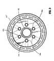
FIGS. 2-6 except that the diameter of annular knife blade 130' has been increased to define a larger unobstructed area withininner chamber 150. Spaces between other surrounding elements of the cartridge assembly radially exterior or outward of the annular knife blade 130' are preferably also compressed. As illustrated, the outer diameter of annular knife 130' is substantially equal to the inner diameter ofcartridge 106. As such, a greater amount of tissue can be severed and retained within shell assembly 107' during use. - Referring to
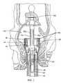
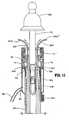
FIGS. 8-11 and according to the present invention, in addition tohollow sleeve 180, the vacuum device includes one ormore vacuum tubes 200 which extend from withinvacuum chamber 182 throughholes 116 of shell assembly 107' intoinner chamber 150 of shell assembly 107'. In one preferred embodiment, a plurality ofvacuum tubes 200 are provided. Each vacuum tube includes afirst end 200a secured to a slidable ring ormanifold 202.Manifold 202 is slidably supported withinvacuum chamber 182 and is fastened to afinger actuator 204 by alink 206.Link 206 may be integrally formed withmanifold 202 andfinger actuator 204. Alternately, these elements may be individually formed and secured together using known fastening techniques.Finger actuator 204 is slidable along an outer surface ofelongated body 104 to movemanifold 202 andvacuum tubes 200 between a retracted (non-deployed) position (FIG. 8 ) and an advanced (deployed) position (FIG. 10 ). Althoughfinger actuator 204 is shown positioned on theelongated body 104, an appropriate linkage may be provided to position the finger actuator adjacent handles 112 (FIG. 1 ).Guide structure 210 may be provided within shell assembly 107' to directvacuum tubes 200 through shell assembly 107'. Vacuum tubes 200 are preferably formed from a flexible material, e.g., plastic, rubber, metals, metal or plastic shape memory materials, etc. A second end of eachvacuum tube 200 extends through arespective hole 116 in shell assembly 107' and is positioned withininner chamber 150 of shell assembly 107'. The location of thesecond end 200b ofvacuum tube 200 can be repositioned by movingfinger actuator 204 in relation toelongated body 104 from a position withininner chamber 150 to a position external of shell assembly 107'. It is envisioned that the length ofvacuum tubes 200 may be selected to facilitate positioning ofend 200b ofvacuum tubes 200 at any location from withininner chamber 150 of shell assembly 107' toanvil assembly 108.Vacuum tubes 200 may also be of a length to engage tissue positioned radially outwardly of shell assembly 107'. In one preferred embodiment illustrated inFIG. 11 , vacuum tubes 200' are formed of a resilient or shape-memory material which naturally curves radially outwardly of shell assembly 107' when vacuum tubes 200' are moved towards the deployed position.Tubes 200 are preferably of a length to engage tissue, e.g., mucosal tissue, defining the inner wall of a lumen, e.g., the anus.Tubes 200 may be deployed to engage tissue and, then, returned to the non-deployed position to pull tissue into the shell assembly.- It will be understood that various modifications may be made to the embodiments disclosed herein Therefore, the above description should not be construed as limiting, but merely as exemplifications of preferred embodiments.
Claims (10)
- A surgical stapling apparatus (100) and vacuum system, the system comprising:a surgical stapling apparatus including a body portion (104), a shell assembly (107') and an anvil (108), the shell assembly being positioned on a distal end of the body portion and including an annular array of staples and at least one aperture (116), the anvil being movably supported in relation to the shell assembly between spaced and approximated positions; anda vacuum device including a housing (180) and a vacuum conduit (186), the housing being positioned about at least a portion of the shell assembly of the surgical stapling apparatus to define a vacuum chamber (182), the at least one aperture being positioned within the vacuum chamber, the vacuum conduit communicating with the vacuum chamber, andcharacterised by at least one vacuum tube (200) having a first end (200a) positioned within the vacuum chamber and a second end (200b) positioned within an inner chamber (150) of the shell assembly.
- A system as recited in Claim 1, wherein the at least one vacuum tube includes a plurality of vacuum tubes.
- A system as recited in Claim 2, further including a manifold (202) slidably positioned within the vacuum chamber, the first end of each of the vacuum tubes being secured to the manifold.
- A system as recited in Claim 3, further including an actuator (204) operably connected to the manifold, the actuator being movable to move the manifold and the plurality of vacuum tubes between a non-deployed position in which the second end of each of the vacuum tubes is positioned within the shell assembly and a deployed position in which the second end of each of the vacuum tubes is positioned external of the shell assembly.
- A system as recited in Claim 4, wherein at least one of the vacuum tubes is formed of a shape-memory material.
- A system as recited in Claim 5, wherein the second end of the at least one of the plurality of vacuum tubes points radially outwardly of the shell assembly in the deployed position.
- A system as recited in Claim 5 or 6, wherein the second end of the at least one of the plurality of vacuum tubes is positioned radially outwardly of the shell assembly in the deployed position.
- A system as recited in any one of the preceding claims, comprising a guide structure (210) within shell assembly to direct the at least one vacuum tube through the shell assembly.
- A system as recited in any one of the preceding claims, wherein the second end of the at least one vacuum tube extends through the at least one aperture.
- A system as recited in any one of the preceding claims, wherein the at least one vacuum tube is formed from a flexible material.
Applications Claiming Priority (3)
| Application Number | Priority Date | Filing Date | Title |
|---|---|---|---|
| US43522302P | 2002-12-20 | 2002-12-20 | |
| US435223P | 2002-12-20 | ||
| PCT/US2003/041068WO2004058080A2 (en) | 2002-12-20 | 2003-12-22 | Vacuum assisted surgical stapler |
Publications (2)
| Publication Number | Publication Date |
|---|---|
| EP1572012A2 EP1572012A2 (en) | 2005-09-14 |
| EP1572012B1true EP1572012B1 (en) | 2008-08-20 |
Family
ID=32682182
Family Applications (1)
| Application Number | Title | Priority Date | Filing Date |
|---|---|---|---|
| EP03814347AExpired - LifetimeEP1572012B1 (en) | 2002-12-20 | 2003-12-22 | Vacuum assisted surgical stapler |
Country Status (8)
| Country | Link |
|---|---|
| US (3) | US8328060B2 (en) |
| EP (1) | EP1572012B1 (en) |
| JP (1) | JP4468821B2 (en) |
| AU (2) | AU2003303337B9 (en) |
| CA (1) | CA2508935C (en) |
| DE (1) | DE60323136D1 (en) |
| ES (1) | ES2311124T3 (en) |
| WO (1) | WO2004058080A2 (en) |
Families Citing this family (190)
| Publication number | Priority date | Publication date | Assignee | Title |
|---|---|---|---|---|
| JP4422027B2 (en) | 2002-10-04 | 2010-02-24 | タイコ ヘルスケア グループ エルピー | Surgical stapling device |
| US8181840B2 (en) | 2004-03-19 | 2012-05-22 | Tyco Healthcare Group Lp | Tissue tensioner assembly and approximation mechanism for surgical stapling device |
| US8123760B2 (en) | 2005-08-05 | 2012-02-28 | Plexus Biomedical, Inc. | Method, apparatus and system for preventing or reducing the severity of hemorrhoids |
| US20070181631A1 (en)* | 2006-02-07 | 2007-08-09 | Ethicon Endo-Surgery, Inc. | Apparatus for performing trans-anal resection |
| US20070239206A1 (en) | 2006-03-31 | 2007-10-11 | Shelton Frederick E Iv | Suture with adhesive/sealant delivery mechanism |
| US7673633B2 (en) | 2006-05-03 | 2010-03-09 | Plexus Biomedical, Inc. | Apparatus and method of inhibiting perianal tissue damage |
| US8540132B2 (en) | 2006-05-16 | 2013-09-24 | Covidien Lp | Tilt anvil assembly |
| JP5070300B2 (en) | 2007-03-07 | 2012-11-07 | コヴィディエン・アクチェンゲゼルシャフト | Mucosal resection stapler |
| US8220689B2 (en)* | 2007-05-02 | 2012-07-17 | Endogene Pty Ltd | Device and method for delivering shape-memory staples |
| EP2200518B1 (en) | 2007-10-11 | 2012-04-25 | Karl-Wilhelm Ecker | Anastomotic tissue connection device |
| US8011554B2 (en)* | 2008-01-09 | 2011-09-06 | Tyco Healthcare Group, Lp | Raised boss for staple guide |
| US8181838B2 (en) | 2008-09-10 | 2012-05-22 | Tyco Healthcare Group Lp | Surgical stapling device |
| US8231042B2 (en) | 2008-11-06 | 2012-07-31 | Tyco Healthcare Group Lp | Surgical stapler |
| US8408441B2 (en)* | 2009-01-06 | 2013-04-02 | Covidien Lp | Surgical stapler |
| US8281974B2 (en) | 2009-01-14 | 2012-10-09 | Tyco Healthcare, Group LP | Surgical stapler with suture locator |
| US8146790B2 (en) | 2009-07-11 | 2012-04-03 | Tyco Healthcare Group Lp | Surgical instrument with safety mechanism |
| US8267301B2 (en) | 2009-08-19 | 2012-09-18 | Tyco Healthcare Group Lp | Surgical stapler |
| US10194904B2 (en)* | 2009-10-08 | 2019-02-05 | Covidien Lp | Surgical staple and method of use |
| US8430292B2 (en) | 2009-10-28 | 2013-04-30 | Covidien Lp | Surgical fastening apparatus |
| US8322590B2 (en) | 2009-10-28 | 2012-12-04 | Covidien Lp | Surgical stapling instrument |
| JP2011224031A (en)* | 2010-04-15 | 2011-11-10 | Fujifilm Corp | Anastomosis apparatus, endoscope system, and method of controlling anastomosis apparatus |
| US8801734B2 (en)* | 2010-07-30 | 2014-08-12 | Ethicon Endo-Surgery, Inc. | Circular stapling instruments with secondary cutting arrangements and methods of using same |
| US8783543B2 (en) | 2010-07-30 | 2014-07-22 | Ethicon Endo-Surgery, Inc. | Tissue acquisition arrangements and methods for surgical stapling devices |
| WO2012042385A2 (en)* | 2010-09-22 | 2012-04-05 | Frankenman International Ltd. | Circular stapler with the capacity to resect and anastomose variable volumes of tissue |
| US8708212B2 (en) | 2011-10-18 | 2014-04-29 | Covidien Lp | Tilt top anvil with torsion spring |
| US9016547B2 (en) | 2011-10-26 | 2015-04-28 | Covidien Lp | EEA tilt top anvil with ratchet/locking mechanism |
| US9173657B2 (en)* | 2011-12-15 | 2015-11-03 | Ethicon Endo-Surgery, Inc. | Devices and methods for endoluminal plication |
| US9010605B2 (en) | 2012-01-12 | 2015-04-21 | Covidien Lp | Sliding sleeve for circular stapling instrument reloads |
| US9022274B2 (en) | 2012-02-15 | 2015-05-05 | Covidien Lp | Circular stapler with increased lumen diameter |
| US9351734B2 (en) | 2012-06-19 | 2016-05-31 | Covidien Lp | Spring loaded anvil retainer |
| US10213205B2 (en) | 2012-07-06 | 2019-02-26 | Covidien Lp | T-slot tilt anvil for circular stapling instrument |
| US9675359B2 (en) | 2012-10-10 | 2017-06-13 | Covidien Lp | Surgical instrument with preload assembly |
| US9572572B2 (en) | 2012-11-09 | 2017-02-21 | Covidien Lp | Circular stapler mechanical lockout |
| US9351724B2 (en) | 2013-01-11 | 2016-05-31 | Covidien Lp | Circular stapling instrument |
| US9592056B2 (en) | 2013-03-14 | 2017-03-14 | Covidien Lp | Powered stapling apparatus |
| US8597306B1 (en) | 2013-03-14 | 2013-12-03 | Plexus Biomedical, Inc. | Labor management methods for decreasing the incidence of cesarean childbirth |
| CN104042292A (en) | 2013-03-15 | 2014-09-17 | 柯惠Lp公司 | Surgical anastomosis device comprising assemblies capable of being repeatedly utilized |
| US9532780B2 (en) | 2013-06-12 | 2017-01-03 | Covidien Lp | EEA anvil snap ring activator |
| US9668740B2 (en) | 2013-06-14 | 2017-06-06 | Covidien Lp | Anvil assembly with sliding sleeve |
| US10271843B2 (en) | 2013-06-17 | 2019-04-30 | Covidien Lp | Surgical instrument with lockout mechanism |
| US9750503B2 (en) | 2013-07-11 | 2017-09-05 | Covidien Lp | Methods and devices for performing a surgical anastomosis |
| US9597074B2 (en)* | 2013-08-15 | 2017-03-21 | Ethicon Endo-Surgery, Llc | Endoluminal stapler with rotating wheel cam for multi-staple firing |
| US9693773B2 (en) | 2013-09-11 | 2017-07-04 | Covidien Lp | Anvil assembly with sliding sleeve |
| WO2015063609A2 (en) | 2013-11-04 | 2015-05-07 | Simcha Milo | Surgical stapler |
| US9517070B2 (en) | 2013-11-13 | 2016-12-13 | Covidien Lp | Anvil assembly and delivery system |
| US9554802B2 (en) | 2013-11-13 | 2017-01-31 | Covidien Lp | Anvil assembly with frangible retaining member |
| US10039546B2 (en)* | 2013-12-23 | 2018-08-07 | Covidien Lp | Loading unit including shipping member |
| US9913643B2 (en) | 2014-05-09 | 2018-03-13 | Covidien Lp | Interlock assemblies for replaceable loading unit |
| CA2949253A1 (en) | 2014-06-12 | 2015-12-17 | Covidien Lp | Surgical stapling apparatus |
| US9861367B2 (en) | 2014-06-24 | 2018-01-09 | Covidien Lp | Anvil assembly delivery systems |
| US9867619B2 (en) | 2014-06-24 | 2018-01-16 | Covidien Lp | System for delivering an anvil assembly to a surgical site |
| WO2016000247A1 (en) | 2014-07-04 | 2016-01-07 | Covidien Lp | Loading unit with shipping member for surgical stapling device |
| US9757133B2 (en) | 2014-07-09 | 2017-09-12 | Covidien Lp | Methods and devices for performing a surgical anastomosis |
| US10085744B2 (en) | 2014-12-08 | 2018-10-02 | Covidien Lp | Loading unit attachment band for surgical stapling instrument |
| US9855045B2 (en) | 2014-12-09 | 2018-01-02 | Covidien Lp | Anvil assembly delivery system |
| WO2016090594A1 (en) | 2014-12-11 | 2016-06-16 | Covidien Lp | Surgical stapling loading unit |
| EP3229708B1 (en) | 2014-12-11 | 2019-08-28 | Covidien LP | Stapler with automatic lockout mechanism |
| JP6518766B2 (en) | 2014-12-17 | 2019-05-22 | コヴィディエン リミテッド パートナーシップ | Surgical stapling device with firing indicator |
| US20190083090A1 (en)* | 2014-12-18 | 2019-03-21 | QuickRing Medical Technologies, Ltd. | Surgical stabilizer |
| US10022126B2 (en) | 2015-01-07 | 2018-07-17 | Covidien Lp | Loading unit locking collar |
| US10039549B2 (en) | 2015-01-07 | 2018-08-07 | Covidien Lp | Loading unit retention clip for surgical stapling instrument |
| US10117656B2 (en) | 2015-01-07 | 2018-11-06 | Covidien Lp | Loading unit locking collar |
| WO2016127433A1 (en) | 2015-02-15 | 2016-08-18 | Covidien Lp | Surgical stapling device with firing indicator of unitary construction |
| US10080520B2 (en) | 2015-02-27 | 2018-09-25 | Stetrix, Inc. | Labor monitoring of pelvic floor |
| KR101740792B1 (en) | 2015-04-09 | 2017-05-29 | 삼성전기주식회사 | Apparatus for transferring wireless power with adjustable voltage gain using variable resonant frequency and method using thererof |
| US10881408B2 (en) | 2015-04-22 | 2021-01-05 | Covidien Lp | Interlock assembly for replaceable loading units |
| US10426480B2 (en) | 2015-04-29 | 2019-10-01 | Covidien Lp | Cutting ring assembly with rigid cutting member |
| US9987001B2 (en) | 2015-06-12 | 2018-06-05 | Covidien Lp | Surgical anastomosis apparatus |
| US9974536B2 (en) | 2015-07-02 | 2018-05-22 | Covidien Lp | Anvil assemblies and delivery systems |
| US10111668B2 (en) | 2015-07-02 | 2018-10-30 | Covidien Lp | Anvil assembly with snap backup ring |
| US10117655B2 (en) | 2015-07-22 | 2018-11-06 | Covidien Lp | Loading unit locking band for surgical stapling instrument |
| US10085756B2 (en) | 2015-07-24 | 2018-10-02 | Covidien Lp | Anvil assembly and anvil assembly delivery system |
| US10117675B2 (en) | 2015-07-28 | 2018-11-06 | Covidien Lp | Trocar tip protector |
| US9980730B2 (en) | 2015-09-21 | 2018-05-29 | Covidien Lp | Loading unit locking collar with rotational actuated release |
| US10111684B2 (en) | 2015-09-25 | 2018-10-30 | Covidien Lp | Adapter assembly including a removable trocar assembly |
| US10542992B2 (en) | 2015-10-19 | 2020-01-28 | Covidien Lp | Loading unit with stretchable bushing |
| CN111803163B (en) | 2015-10-20 | 2024-04-26 | 柯惠有限合伙公司 | Circular stapler with tissue gap indicator assembly |
| US10842495B2 (en) | 2015-10-21 | 2020-11-24 | Covidien Lp | Annular knife for a surgical stapler |
| US10512466B2 (en) | 2015-11-05 | 2019-12-24 | Covidien Lp | Adapter assembly for surgical device |
| WO2017079970A1 (en) | 2015-11-13 | 2017-05-18 | Covidien Lp | Circular stapler with audible indicator mechanism |
| WO2017096502A1 (en) | 2015-12-07 | 2017-06-15 | Covidien Lp | Anvil assembly and delivery system |
| US10390835B2 (en) | 2015-12-10 | 2019-08-27 | Covidien Lp | Surgical fastener apparatus with linear position sensor |
| US10966717B2 (en)* | 2016-01-07 | 2021-04-06 | Covidien Lp | Surgical fastener apparatus |
| US10524797B2 (en) | 2016-01-13 | 2020-01-07 | Covidien Lp | Adapter assembly including a removable trocar assembly |
| EP3410957B1 (en) | 2016-02-04 | 2020-06-03 | Covidien LP | Circular stapler with visual indicator mechanism |
| US10398439B2 (en) | 2016-02-10 | 2019-09-03 | Covidien Lp | Adapter, extension, and connector assemblies for surgical devices |
| US10603042B2 (en) | 2016-02-10 | 2020-03-31 | Covidien Lp | Flexible circular stapler |
| US10595871B2 (en) | 2016-05-10 | 2020-03-24 | Covidien Lp | Insertion instrument, adapter assemblies and protector assemblies for a flexible circular stapler |
| US11141162B2 (en) | 2016-07-08 | 2021-10-12 | Covidien Lp | Loading unit locking collar with linearly actuated release |
| US11452522B2 (en) | 2016-08-15 | 2022-09-27 | Covidien Lp | Circular stapling device with articulating anvil retainer assembly |
| US10499922B2 (en) | 2016-11-04 | 2019-12-10 | Covidien Lp | Stapling device with self-releasing knife carrier pusher |
| US10426470B2 (en) | 2016-11-04 | 2019-10-01 | Covidien Lp | Stapling device with releasable knife carrier |
| US11241232B2 (en) | 2017-01-24 | 2022-02-08 | Covidien Lp | Surgical stapling device with resettable anvil assembly |
| EP3573543A4 (en) | 2017-01-25 | 2021-03-03 | Covidien LP | Circular stapling device and method of use |
| US11497507B2 (en) | 2017-02-19 | 2022-11-15 | Orpheus Ventures, Llc | Systems and methods for closing portions of body tissue |
| US10542993B2 (en) | 2017-02-24 | 2020-01-28 | Covidien Lp | Anvil assembly of circular stapling device including alignment splines |
| WO2018161314A1 (en) | 2017-03-09 | 2018-09-13 | Covidien Lp | Surgical stapling device with audible indicator mechanism |
| WO2018161301A1 (en) | 2017-03-09 | 2018-09-13 | Covidien Lp | End effector assembly for circular stapler apparatus |
| US10342534B2 (en) | 2017-03-23 | 2019-07-09 | Covidien Lp | Surgical stapling device with releasable knife carrier |
| US11071549B2 (en) | 2017-03-23 | 2021-07-27 | Covidien Lp | Circular stapling device with alignment splines |
| US10881409B2 (en) | 2017-05-02 | 2021-01-05 | Covidien Lp | Rotation assembly for a surgical device |
| JP7278717B2 (en)* | 2017-05-30 | 2023-05-22 | コヴィディエン リミテッド パートナーシップ | A method for inserting a circular stapling device into a body lumen |
| US10932784B2 (en) | 2017-06-09 | 2021-03-02 | Covidien Lp | Handheld electromechanical surgical system |
| US11045199B2 (en) | 2017-06-09 | 2021-06-29 | Covidien Lp | Handheld electromechanical surgical system |
| US11596400B2 (en) | 2017-06-09 | 2023-03-07 | Covidien Lp | Handheld electromechanical surgical system |
| US10987107B2 (en) | 2017-07-05 | 2021-04-27 | Covidien Lp | Surgical stapling device |
| US11090054B2 (en) | 2017-08-07 | 2021-08-17 | Covidien Lp | Stapling device with resettable tilt anvil assembly |
| US10828026B2 (en) | 2017-08-08 | 2020-11-10 | Covidien Lp | Tiltable anvil assembly |
| US10695069B2 (en) | 2017-08-23 | 2020-06-30 | Covidien Lp | Circular stapling device with offset spline tip |
| EP3675748B1 (en) | 2017-09-01 | 2024-06-12 | Covidien LP | Circular stapling device with position ribs |
| US11324507B2 (en) | 2017-11-03 | 2022-05-10 | Covidien Lp | Device and method for attachment of a stomal sleeve |
| US11497501B2 (en) | 2018-03-26 | 2022-11-15 | Covidien Lp | Circular stapling device with A-frame splines |
| US11006959B2 (en) | 2018-03-28 | 2021-05-18 | Covidien Lp | Surgical anvil assemblies for surgical stapling instruments |
| US10952734B2 (en) | 2018-04-23 | 2021-03-23 | Covidien Lp | Stapling device with cut ring biasing member |
| US11197676B2 (en) | 2018-06-28 | 2021-12-14 | Covidien Lp | Tie-down method for anvil assembly delivery system |
| US11241234B2 (en) | 2018-08-14 | 2022-02-08 | Covidien Lp | Anvil assembly with self-retaining backup member |
| US11564691B2 (en) | 2018-08-24 | 2023-01-31 | Covidien Lp | Powered circular stapling device |
| US10973544B2 (en) | 2018-10-02 | 2021-04-13 | Covidien Lp | Retaining mechanism for trocar assembly |
| US11141163B2 (en) | 2018-10-04 | 2021-10-12 | Covidien Lp | Circular stapling device with anvil rotation locking structure |
| US11065005B2 (en) | 2018-11-07 | 2021-07-20 | Covidien Lp | Reload assembly for a circular stapling device |
| US11147561B2 (en) | 2018-11-28 | 2021-10-19 | Covidien Lp | Reload assembly for a circular stapling device |
| US11389263B2 (en) | 2018-12-13 | 2022-07-19 | Covidien Lp | Lockout mechanisms for surgical instruments |
| US11166728B2 (en) | 2019-02-08 | 2021-11-09 | Covidien Lp | Reload assembly for a circular stapling device |
| US11547411B2 (en) | 2019-02-22 | 2023-01-10 | Covidien Lp | Anastomosis wound protector |
| US11529144B2 (en) | 2019-02-22 | 2022-12-20 | Covidien Lp | Encapsulated plug assembly for electromechanical surgical devices |
| US11331782B2 (en) | 2019-03-01 | 2022-05-17 | Covidien Lp | Reload assembly for a circular stapling device |
| US11337701B2 (en) | 2019-03-01 | 2022-05-24 | Covidien Lp | Devices and methods for assembling adapter assemblies |
| US11457921B2 (en) | 2019-03-26 | 2022-10-04 | Covidien Lp | Anvil assembly for surgical stapling instrument |
| US11534164B2 (en) | 2019-04-05 | 2022-12-27 | Covidien Lp | Strain gauge stabilization in a surgical device |
| US11596410B2 (en) | 2019-04-05 | 2023-03-07 | Covidien Lp | Surgical stapling device |
| US11344330B2 (en) | 2019-04-16 | 2022-05-31 | Covidien Lp | Trocar assemblies for adapter assemblies for surgical stapling instruments |
| US11317945B2 (en) | 2019-04-16 | 2022-05-03 | Covidien Lp | Trocar assemblies for adapter assemblies for surgical stapling instruments |
| US11419631B2 (en) | 2019-04-16 | 2022-08-23 | Covidien Lp | Trocar assemblies for adapter assemblies for surgical stapling instruments |
| US11660116B2 (en) | 2019-04-16 | 2023-05-30 | Covidien Lp | Trocar assemblies for adapter assemblies for surgical stapling instruments |
| US11839378B2 (en) | 2019-04-19 | 2023-12-12 | Covidien Lp | Circular stapling instruments |
| US11399838B2 (en) | 2019-04-22 | 2022-08-02 | Covidien Lp | Reload assembly for circular stapling devices |
| US11246599B2 (en) | 2019-04-25 | 2022-02-15 | Covidien Lp | End effector for circular stapling instrument |
| CA3139541A1 (en) | 2019-05-31 | 2020-12-03 | Covidien Lp | Circular stapling device |
| US11690624B2 (en) | 2019-06-21 | 2023-07-04 | Covidien Lp | Reload assembly injection molded strain gauge |
| US11446035B2 (en) | 2019-06-24 | 2022-09-20 | Covidien Lp | Retaining mechanisms for trocar assemblies |
| US11123101B2 (en) | 2019-07-05 | 2021-09-21 | Covidien Lp | Retaining mechanisms for trocar assemblies |
| US11344309B2 (en) | 2019-07-05 | 2022-05-31 | Covidien Lp | Circular stapling instruments |
| US11357509B2 (en) | 2019-07-11 | 2022-06-14 | Covidien Lp | Reload assembly for a circular stapling device |
| US11192227B2 (en) | 2019-07-16 | 2021-12-07 | Covidien Lp | Reload assembly for circular stapling devices |
| US11464510B2 (en) | 2019-07-26 | 2022-10-11 | Covidien Lp | Reload assembly with knife carrier lockout |
| US11253255B2 (en) | 2019-07-26 | 2022-02-22 | Covidien Lp | Knife lockout wedge |
| US11399825B2 (en) | 2019-10-28 | 2022-08-02 | Covidien Lp | Reload assembly with knife carrier lockout |
| US11553918B2 (en) | 2019-12-16 | 2023-01-17 | Covidien Lp | Reload assembly with knife carrier lockout |
| US11730481B2 (en) | 2020-01-06 | 2023-08-22 | Covidien Lp | Assemblies for retaining a trocar assembly |
| US11517317B2 (en) | 2020-01-06 | 2022-12-06 | Covidien Lp | Trocar release assemblies for a surgical stapler |
| US11911038B2 (en) | 2020-01-13 | 2024-02-27 | Covidien Lp | Cut optimization for excessive tissue conditions |
| US11523828B2 (en) | 2020-01-28 | 2022-12-13 | Covidien Lp | Sealed reload assembly for stapling device |
| US11622767B2 (en) | 2020-02-19 | 2023-04-11 | Covidien Lp | Sealed trocar assembly for stapling device |
| US11547438B2 (en) | 2020-02-24 | 2023-01-10 | Covidien Lp | Tip protector for ensuring trocar insertion |
| US11382630B2 (en) | 2020-02-25 | 2022-07-12 | Covidien Lp | Surgical stapling device with two part knife assembly |
| US11779343B2 (en) | 2020-02-26 | 2023-10-10 | Covidien Lp | Staple reload assembly with releasable knife |
| US11298152B2 (en) | 2020-02-28 | 2022-04-12 | Covidien Lp | Trocar retaining mechanism including band support |
| US11272998B2 (en) | 2020-03-04 | 2022-03-15 | Covidien Lp | Strain gage fixation in tension |
| US11426169B2 (en) | 2020-03-24 | 2022-08-30 | Covidien Lp | Retaining mechanisms for trocar assemblies |
| US11350939B2 (en) | 2020-03-24 | 2022-06-07 | Covidien Lp | Retaining mechanisms for trocar assemblies |
| US11426170B2 (en) | 2020-03-24 | 2022-08-30 | Covidien Lp | Retaining mechanisms for trocar assemblies |
| US11653925B2 (en) | 2020-05-21 | 2023-05-23 | Covidien Lp | Tissue relaxation monitoring for optimized tissue stapling |
| US11547405B2 (en) | 2020-05-22 | 2023-01-10 | Covidien Lp | Surgical stapling device |
| US11553921B2 (en) | 2020-07-15 | 2023-01-17 | Covidien Lp | Surgical stapling device with flexible shaft |
| US11547412B2 (en) | 2020-07-22 | 2023-01-10 | Covidien Lp | Surgical instruments and methods of assembly |
| US11871925B2 (en) | 2020-07-28 | 2024-01-16 | Cilag Gmbh International | Surgical instruments with dual spherical articulation joint arrangements |
| US11877744B2 (en) | 2020-08-14 | 2024-01-23 | Covidien Lp | Low-cost powered stapler with end stop selection |
| US11627966B2 (en) | 2020-08-26 | 2023-04-18 | Covidien Lp | Surgical stapling device |
| US11801054B2 (en) | 2020-09-22 | 2023-10-31 | Covidien Lp | Surgical stapler with oval tool assembly |
| US11712509B2 (en) | 2020-10-02 | 2023-08-01 | Covidien Lp | Seal assembly for circular stapling instrument |
| US11534259B2 (en) | 2020-10-29 | 2022-12-27 | Cilag Gmbh International | Surgical instrument comprising an articulation indicator |
| US11896217B2 (en) | 2020-10-29 | 2024-02-13 | Cilag Gmbh International | Surgical instrument comprising an articulation lock |
| US11627967B2 (en) | 2020-11-23 | 2023-04-18 | Covidien Lp | Trans-anastomotic insertion device |
| EP4262580B1 (en) | 2020-12-15 | 2025-10-08 | Covidien LP | Surgical stapling device rotatable camming element |
| US11877750B2 (en) | 2021-01-21 | 2024-01-23 | Covidien Lp | Surgical stapler with powered and manual functions |
| US11986187B2 (en) | 2021-01-29 | 2024-05-21 | Covidien Lp | Circular stapling device with integrated visualization device |
| US11786241B2 (en) | 2021-02-16 | 2023-10-17 | Covidien Lp | Surgical stapling device including a hydraulic staple formation mechanism |
| US11553920B2 (en) | 2021-05-03 | 2023-01-17 | Covidien Lp | Trocar retainer assembly for surgical stapler |
| US11490894B1 (en) | 2021-05-12 | 2022-11-08 | Covidien Lp | Surgical device with grease filter |
| US11642131B2 (en) | 2021-05-17 | 2023-05-09 | Covidien Lp | Devices and methods for shortening a rectal stump during a lower anterior resection procedure |
| CN117715596A (en) | 2021-05-24 | 2024-03-15 | 柯惠有限合伙公司 | Anvil and delivery system components with automatic holding suture release |
| US11612400B2 (en) | 2021-05-24 | 2023-03-28 | Covidien Lp | Trocar assembly with bearing assembly for load sharing |
| US20230000495A1 (en)* | 2021-06-30 | 2023-01-05 | Covidien Lp | Circular stapling device with tissue grasping members |
| US11737759B2 (en) | 2021-08-05 | 2023-08-29 | Covidien Lp | Surgical stapling device accommodating prolapsed tissue |
| US11819208B2 (en) | 2021-08-05 | 2023-11-21 | Covidien Lp | Handheld electromechanical surgical device with strain gauge drift detection |
| US11744592B2 (en) | 2021-08-05 | 2023-09-05 | Covidien Lp | Handheld electromechanical stapler with tissue thickness detection |
| US11883028B2 (en) | 2021-09-08 | 2024-01-30 | Covidien Lp | Systems and methods for post-operative anastomotic leak detection |
| US11717299B2 (en) | 2021-10-12 | 2023-08-08 | Covidien Lp | Surgical stapling device with probiotics |
| US12329669B2 (en) | 2021-10-27 | 2025-06-17 | Stetrix, Inc. | Perianal support device with flexible side supports |
| US12213674B2 (en) | 2021-12-08 | 2025-02-04 | Covidien Lp | Determination of premature staple ejection |
Family Cites Families (36)
| Publication number | Priority date | Publication date | Assignee | Title |
|---|---|---|---|---|
| SU1088712A1 (en)* | 1979-11-14 | 1984-04-30 | Всесоюзный научно-исследовательский и испытательный институт медицинской техники | Apparatus for circular suture of blood vessels |
| US4319576A (en)* | 1980-02-26 | 1982-03-16 | Senco Products, Inc. | Intralumenal anastomosis surgical stapling instrument |
| US4602634A (en)* | 1983-09-23 | 1986-07-29 | Ethicon, Inc. | Method and instrument for applying a fastener to a tissue using means to grasp, guide and pull the fastener through the tissue |
| US4893622A (en)* | 1986-10-17 | 1990-01-16 | United States Surgical Corporation | Method of stapling tubular body organs |
| US5119983A (en)* | 1987-05-26 | 1992-06-09 | United States Surgical Corporation | Surgical stapler apparatus |
| US5542949A (en)* | 1987-05-14 | 1996-08-06 | Yoon; Inbae | Multifunctional clip applier instrument |
| US4990153A (en)* | 1988-10-07 | 1991-02-05 | Ophthalmic Ventures Limited Partnership | Surgical suturing system and probe assembly |
| US5104394A (en)* | 1990-11-05 | 1992-04-14 | Knoepfler Dennis J | Automatic stapler for laparoscopic procedure with selective cutter and suction irrigator |
| US5282807A (en)* | 1990-11-05 | 1994-02-01 | Knoepfler Dennis J | Automatic stapler for laparoscopic procedure with selective cutter, nontraumatic jaws and suction irrigator |
| GR920100358A (en)* | 1991-08-23 | 1993-06-07 | Ethicon Inc | Surgical anastomosis stapling instrument. |
| US5443198A (en)* | 1991-10-18 | 1995-08-22 | United States Surgical Corporation | Surgical fastener applying apparatus |
| US5389098A (en)* | 1992-05-19 | 1995-02-14 | Olympus Optical Co., Ltd. | Surgical device for stapling and/or fastening body tissues |
| JPH0647050A (en)* | 1992-06-04 | 1994-02-22 | Olympus Optical Co Ltd | Tissue suture and ligature device |
| US5322161A (en)* | 1992-11-30 | 1994-06-21 | United States Surgical Corporation | Clear package for bioabsorbable articles |
| US5827323A (en)* | 1993-07-21 | 1998-10-27 | Charles H. Klieman | Surgical instrument for endoscopic and general surgery |
| US5503635A (en)* | 1993-11-12 | 1996-04-02 | United States Surgical Corporation | Apparatus and method for performing compressional anastomoses |
| US5839639A (en)* | 1995-08-17 | 1998-11-24 | Lasersurge, Inc. | Collapsible anvil assembly and applicator instrument |
| US6601749B2 (en)* | 1998-06-19 | 2003-08-05 | Scimed Life Systems, Inc. | Multi fire full thickness resectioning device |
| US6126058A (en)* | 1998-06-19 | 2000-10-03 | Scimed Life Systems, Inc. | Method and device for full thickness resectioning of an organ |
| US6165183A (en)* | 1998-07-15 | 2000-12-26 | St. Jude Medical, Inc. | Mitral and tricuspid valve repair |
| US6083241A (en)* | 1998-11-23 | 2000-07-04 | Ethicon Endo-Surgery, Inc. | Method of use of a circular stapler for hemorrhoidal procedure |
| US6506196B1 (en)* | 1999-06-22 | 2003-01-14 | Ndo Surgical, Inc. | Device and method for correction of a painful body defect |
| US6193129B1 (en)* | 2000-01-24 | 2001-02-27 | Ethicon Endo-Surgery, Inc. | Cutting blade for a surgical anastomosis stapling instrument |
| US6544271B1 (en)* | 2000-07-18 | 2003-04-08 | Scimed Life Systems, Inc. | Device for full-thickness resectioning of an organ |
| US20020082621A1 (en)* | 2000-09-22 | 2002-06-27 | Schurr Marc O. | Methods and devices for folding and securing tissue |
| EP2397080B1 (en) | 2001-04-03 | 2018-08-01 | Covidien LP | Surgical stapling device |
| US6632227B2 (en)* | 2001-08-24 | 2003-10-14 | Scimed Life Systems, Inc. | Endoscopic resection devices |
| US6575971B2 (en)* | 2001-11-15 | 2003-06-10 | Quantum Cor, Inc. | Cardiac valve leaflet stapler device and methods thereof |
| WO2003053255A1 (en)* | 2001-12-20 | 2003-07-03 | Tyco Healthcare Group Lp | Surgical stapler apparatus |
| US7094244B2 (en)* | 2002-03-26 | 2006-08-22 | Edwards Lifesciences Corporation | Sequential heart valve leaflet repair device and method of use |
| US20040217146A1 (en)* | 2002-12-20 | 2004-11-04 | Joachim Beck | Surgical stapler apparatus and method |
| US7914543B2 (en)* | 2003-10-14 | 2011-03-29 | Satiety, Inc. | Single fold device for tissue fixation |
| US7097650B2 (en)* | 2003-10-14 | 2006-08-29 | Satiety, Inc. | System for tissue approximation and fixation |
| US8590764B2 (en)* | 2003-12-24 | 2013-11-26 | Boston Scientific Scimed, Inc. | Circumferential full thickness resectioning device |
| JP4257270B2 (en)* | 2004-07-14 | 2009-04-22 | オリンパス株式会社 | Biological tissue suturing method and biological tissue suturing device |
| US20090125040A1 (en)* | 2006-09-13 | 2009-05-14 | Hambly Pablo R | Tissue acquisition devices and methods |
- 2003
- 2003-12-22EPEP03814347Apatent/EP1572012B1/ennot_activeExpired - Lifetime
- 2003-12-22ESES03814347Tpatent/ES2311124T3/ennot_activeExpired - Lifetime
- 2003-12-22JPJP2004563990Apatent/JP4468821B2/ennot_activeExpired - Fee Related
- 2003-12-22WOPCT/US2003/041068patent/WO2004058080A2/enactiveApplication Filing
- 2003-12-22USUS10/540,197patent/US8328060B2/ennot_activeExpired - Fee Related
- 2003-12-22DEDE60323136Tpatent/DE60323136D1/ennot_activeExpired - Lifetime
- 2003-12-22CACA2508935Apatent/CA2508935C/ennot_activeExpired - Fee Related
- 2003-12-22AUAU2003303337Apatent/AU2003303337B9/ennot_activeCeased
- 2008
- 2008-08-18AUAU2008207370Apatent/AU2008207370B2/ennot_activeCeased
- 2012
- 2012-08-09USUS13/571,290patent/US20130020372A1/ennot_activeAbandoned
- 2014
- 2014-06-03USUS14/294,647patent/US9681872B2/ennot_activeExpired - Fee Related
Also Published As
| Publication number | Publication date |
|---|---|
| DE60323136D1 (en) | 2008-10-02 |
| ES2311124T3 (en) | 2009-02-01 |
| US8328060B2 (en) | 2012-12-11 |
| US20140263573A1 (en) | 2014-09-18 |
| CA2508935C (en) | 2011-03-15 |
| JP4468821B2 (en) | 2010-05-26 |
| WO2004058080A3 (en) | 2004-09-10 |
| AU2003303337B8 (en) | 2008-06-26 |
| US20060144897A1 (en) | 2006-07-06 |
| US9681872B2 (en) | 2017-06-20 |
| WO2004058080A2 (en) | 2004-07-15 |
| US20130020372A1 (en) | 2013-01-24 |
| AU2003303337B2 (en) | 2008-06-05 |
| EP1572012A2 (en) | 2005-09-14 |
| CA2508935A1 (en) | 2004-07-15 |
| AU2003303337B9 (en) | 2008-11-20 |
| JP2006511277A (en) | 2006-04-06 |
| AU2008207370B2 (en) | 2010-09-09 |
| AU2003303337A1 (en) | 2004-07-22 |
| AU2008207370A1 (en) | 2008-09-11 |
Similar Documents
| Publication | Publication Date | Title |
|---|---|---|
| EP1572012B1 (en) | Vacuum assisted surgical stapler | |
| US20040217146A1 (en) | Surgical stapler apparatus and method | |
| US6102271A (en) | Circular stapler for hemorrhoidal surgery | |
| US6083241A (en) | Method of use of a circular stapler for hemorrhoidal procedure | |
| US6142933A (en) | Anoscope for hemorrhoidal surgery | |
| US5309927A (en) | Circular stapler tissue retention spring method | |
| US7399305B2 (en) | Surgical stapling device with tissue tensioner | |
| US8590764B2 (en) | Circumferential full thickness resectioning device | |
| US7141055B2 (en) | Resection and anastomosis devices and methods | |
| US5314435A (en) | Anvil delivery system | |
| JPH06165785A (en) | Anvil bushing for circular stapler | |
| KR102072045B1 (en) | C-shaped hemorrhoidal stapler | |
| EP1455658A1 (en) | Surgical stapler apparatus | |
| CN114126510A (en) | Device and method for examining and treating hemorrhoids | |
| US20220395275A1 (en) | Surgical fastening instrument |
Legal Events
| Date | Code | Title | Description |
|---|---|---|---|
| PUAI | Public reference made under article 153(3) epc to a published international application that has entered the european phase | Free format text:ORIGINAL CODE: 0009012 | |
| 17P | Request for examination filed | Effective date:20050624 | |
| AK | Designated contracting states | Kind code of ref document:A2 Designated state(s):AT BE BG CH CY CZ DE DK EE ES FI FR GB GR HU IE IT LI LU MC NL PT RO SE SI SK TR | |
| AX | Request for extension of the european patent | Extension state:AL LT LV MK | |
| DAX | Request for extension of the european patent (deleted) | ||
| RBV | Designated contracting states (corrected) | Designated state(s):DE ES FR GB IE IT | |
| RIN1 | Information on inventor provided before grant (corrected) | Inventor name:JANKOWSKI, BRUCE Inventor name:WITTMANN, JOSEPH | |
| 17Q | First examination report despatched | Effective date:20070720 | |
| GRAP | Despatch of communication of intention to grant a patent | Free format text:ORIGINAL CODE: EPIDOSNIGR1 | |
| GRAS | Grant fee paid | Free format text:ORIGINAL CODE: EPIDOSNIGR3 | |
| GRAA | (expected) grant | Free format text:ORIGINAL CODE: 0009210 | |
| AK | Designated contracting states | Kind code of ref document:B1 Designated state(s):DE ES FR GB IE IT | |
| REG | Reference to a national code | Ref country code:GB Ref legal event code:FG4D | |
| REG | Reference to a national code | Ref country code:IE Ref legal event code:FG4D | |
| REF | Corresponds to: | Ref document number:60323136 Country of ref document:DE Date of ref document:20081002 Kind code of ref document:P | |
| REG | Reference to a national code | Ref country code:ES Ref legal event code:FG2A Ref document number:2311124 Country of ref document:ES Kind code of ref document:T3 | |
| PLBE | No opposition filed within time limit | Free format text:ORIGINAL CODE: 0009261 | |
| STAA | Information on the status of an ep patent application or granted ep patent | Free format text:STATUS: NO OPPOSITION FILED WITHIN TIME LIMIT | |
| 26N | No opposition filed | Effective date:20090525 | |
| PGFP | Annual fee paid to national office [announced via postgrant information from national office to epo] | Ref country code:IT Payment date:20101223 Year of fee payment:8 | |
| PGFP | Annual fee paid to national office [announced via postgrant information from national office to epo] | Ref country code:ES Payment date:20111226 Year of fee payment:9 | |
| PG25 | Lapsed in a contracting state [announced via postgrant information from national office to epo] | Ref country code:IT Free format text:LAPSE BECAUSE OF NON-PAYMENT OF DUE FEES Effective date:20121222 | |
| REG | Reference to a national code | Ref country code:ES Ref legal event code:FD2A Effective date:20140527 | |
| PG25 | Lapsed in a contracting state [announced via postgrant information from national office to epo] | Ref country code:ES Free format text:LAPSE BECAUSE OF NON-PAYMENT OF DUE FEES Effective date:20121223 | |
| REG | Reference to a national code | Ref country code:FR Ref legal event code:PLFP Year of fee payment:13 | |
| PGFP | Annual fee paid to national office [announced via postgrant information from national office to epo] | Ref country code:IE Payment date:20151123 Year of fee payment:13 Ref country code:GB Payment date:20151125 Year of fee payment:13 | |
| PGFP | Annual fee paid to national office [announced via postgrant information from national office to epo] | Ref country code:FR Payment date:20151123 Year of fee payment:13 | |
| PGFP | Annual fee paid to national office [announced via postgrant information from national office to epo] | Ref country code:DE Payment date:20161121 Year of fee payment:14 | |
| GBPC | Gb: european patent ceased through non-payment of renewal fee | Effective date:20161222 | |
| REG | Reference to a national code | Ref country code:FR Ref legal event code:ST Effective date:20170831 | |
| REG | Reference to a national code | Ref country code:IE Ref legal event code:MM4A | |
| PG25 | Lapsed in a contracting state [announced via postgrant information from national office to epo] | Ref country code:FR Free format text:LAPSE BECAUSE OF NON-PAYMENT OF DUE FEES Effective date:20170102 | |
| PG25 | Lapsed in a contracting state [announced via postgrant information from national office to epo] | Ref country code:IE Free format text:LAPSE BECAUSE OF NON-PAYMENT OF DUE FEES Effective date:20161222 Ref country code:GB Free format text:LAPSE BECAUSE OF NON-PAYMENT OF DUE FEES Effective date:20161222 | |
| REG | Reference to a national code | Ref country code:DE Ref legal event code:R119 Ref document number:60323136 Country of ref document:DE | |
| PG25 | Lapsed in a contracting state [announced via postgrant information from national office to epo] | Ref country code:DE Free format text:LAPSE BECAUSE OF NON-PAYMENT OF DUE FEES Effective date:20180703 |