EP1570549B1 - Connector assembly - Google Patents
Connector assemblyDownload PDFInfo
- Publication number
- EP1570549B1 EP1570549B1EP03779307AEP03779307AEP1570549B1EP 1570549 B1EP1570549 B1EP 1570549B1EP 03779307 AEP03779307 AEP 03779307AEP 03779307 AEP03779307 AEP 03779307AEP 1570549 B1EP1570549 B1EP 1570549B1
- Authority
- EP
- European Patent Office
- Prior art keywords
- header
- carrier
- housing
- vertical wall
- disposed
- Prior art date
- Legal status (The legal status is an assumption and is not a legal conclusion. Google has not performed a legal analysis and makes no representation as to the accuracy of the status listed.)
- Expired - Lifetime
Links
- 230000000712assemblyEffects0.000claimsabstractdescription27
- 238000000429assemblyMethods0.000claimsabstractdescription27
- 238000003780insertionMethods0.000claimsdescription10
- 230000037431insertionEffects0.000claimsdescription10
- 238000004891communicationMethods0.000claimsdescription4
- 239000011810insulating materialSubstances0.000description2
- 238000004519manufacturing processMethods0.000description2
- 230000008054signal transmissionEffects0.000description2
- UTMWFJSRHLYRPY-UHFFFAOYSA-N3,3',5,5'-tetrachlorobiphenylChemical compoundClC1=CC(Cl)=CC(C=2C=C(Cl)C=C(Cl)C=2)=C1UTMWFJSRHLYRPY-UHFFFAOYSA-N0.000description1
- 230000005540biological transmissionEffects0.000description1
- 239000004020conductorSubstances0.000description1
- 238000005516engineering processMethods0.000description1
- 238000001746injection mouldingMethods0.000description1
- 230000013011matingEffects0.000description1
- 229910000679solderInorganic materials0.000description1
Images


Classifications
- H—ELECTRICITY
- H01—ELECTRIC ELEMENTS
- H01R—ELECTRICALLY-CONDUCTIVE CONNECTIONS; STRUCTURAL ASSOCIATIONS OF A PLURALITY OF MUTUALLY-INSULATED ELECTRICAL CONNECTING ELEMENTS; COUPLING DEVICES; CURRENT COLLECTORS
- H01R13/00—Details of coupling devices of the kinds covered by groups H01R12/70 or H01R24/00 - H01R33/00
- H01R13/58—Means for relieving strain on wire connection, e.g. cord grip, for avoiding loosening of connections between wires and terminals within a coupling device terminating a cable
- H01R13/5804—Means for relieving strain on wire connection, e.g. cord grip, for avoiding loosening of connections between wires and terminals within a coupling device terminating a cable comprising a separate cable clamping part
- H01R13/5812—Means for relieving strain on wire connection, e.g. cord grip, for avoiding loosening of connections between wires and terminals within a coupling device terminating a cable comprising a separate cable clamping part the cable clamping being achieved by mounting the separate part on the housing of the coupling device
- H—ELECTRICITY
- H01—ELECTRIC ELEMENTS
- H01R—ELECTRICALLY-CONDUCTIVE CONNECTIONS; STRUCTURAL ASSOCIATIONS OF A PLURALITY OF MUTUALLY-INSULATED ELECTRICAL CONNECTING ELEMENTS; COUPLING DEVICES; CURRENT COLLECTORS
- H01R13/00—Details of coupling devices of the kinds covered by groups H01R12/70 or H01R24/00 - H01R33/00
- H01R13/46—Bases; Cases
- H01R13/514—Bases; Cases composed as a modular blocks or assembly, i.e. composed of co-operating parts provided with contact members or holding contact members between them
- H—ELECTRICITY
- H01—ELECTRIC ELEMENTS
- H01R—ELECTRICALLY-CONDUCTIVE CONNECTIONS; STRUCTURAL ASSOCIATIONS OF A PLURALITY OF MUTUALLY-INSULATED ELECTRICAL CONNECTING ELEMENTS; COUPLING DEVICES; CURRENT COLLECTORS
- H01R13/00—Details of coupling devices of the kinds covered by groups H01R12/70 or H01R24/00 - H01R33/00
- H01R13/646—Details of coupling devices of the kinds covered by groups H01R12/70 or H01R24/00 - H01R33/00 specially adapted for high-frequency, e.g. structures providing an impedance match or phase match
- H01R13/6473—Impedance matching
- H—ELECTRICITY
- H01—ELECTRIC ELEMENTS
- H01R—ELECTRICALLY-CONDUCTIVE CONNECTIONS; STRUCTURAL ASSOCIATIONS OF A PLURALITY OF MUTUALLY-INSULATED ELECTRICAL CONNECTING ELEMENTS; COUPLING DEVICES; CURRENT COLLECTORS
- H01R13/00—Details of coupling devices of the kinds covered by groups H01R12/70 or H01R24/00 - H01R33/00
- H01R13/648—Protective earth or shield arrangements on coupling devices, e.g. anti-static shielding
- H01R13/658—High frequency shielding arrangements, e.g. against EMI [Electro-Magnetic Interference] or EMP [Electro-Magnetic Pulse]
- H01R13/6591—Specific features or arrangements of connection of shield to conductive members
- H01R13/6592—Specific features or arrangements of connection of shield to conductive members the conductive member being a shielded cable
- H—ELECTRICITY
- H01—ELECTRIC ELEMENTS
- H01R—ELECTRICALLY-CONDUCTIVE CONNECTIONS; STRUCTURAL ASSOCIATIONS OF A PLURALITY OF MUTUALLY-INSULATED ELECTRICAL CONNECTING ELEMENTS; COUPLING DEVICES; CURRENT COLLECTORS
- H01R13/00—Details of coupling devices of the kinds covered by groups H01R12/70 or H01R24/00 - H01R33/00
- H01R13/648—Protective earth or shield arrangements on coupling devices, e.g. anti-static shielding
- H01R13/658—High frequency shielding arrangements, e.g. against EMI [Electro-Magnetic Interference] or EMP [Electro-Magnetic Pulse]
- H01R13/6581—Shield structure
- H01R13/6585—Shielding material individually surrounding or interposed between mutually spaced contacts
Definitions
- the present inventionrelates to a high speed connector.
- the present inventionrelates to a connector that provides for controlled impedance and allows for quick and easy replacement of components.
- Interconnection of integrated circuits to other circuit boards, cables or electronic devicesis known in the art. Such interconnections typically have not been difficult to form, especially when the circuit switching speeds (also referred to as signal transmission times) have been slow when compared to the length of time required for a signal to propagate through a conductor in the interconnect or in the printed circuit board. As signal transmission times continue to increase with modem integrated circuits and related computer technology, the design and manufacture of interconnects that can perform satisfactorily has grown more difficult.
- Connectorshave been developed to provide the necessary impedance control for high speed circuits, i.e., circuits with a transmission frequency of at least 5 GHz. Although many of these connectors are useful, there is still a need in the art for different and more economical connector designs that provide for easy component replacements.
- the present inventionpertains to a connector assembly designed to provide controlled impedance to maintain signal and ground integrity, and to allow for quick and easy assembly and disassembly for replacing components or for modifying or upgrading with different components. In this way, the present invention provides economic advantages to the consumer in that only the selected component in the connector assembly needs to be replaced instead of replacing the entire assembly.
- the present inventionprovides a carrier for use with an electrical connector assembly.
- the carriercomprises an insulating housing and means for securing the terminated cable assemblies.
- the carrierfurther comprises a means for managing the terminated cable assemblies.
- means for securing and means for managing the terminated cable assembliesare integrated.
- the housingincludes a front vertical wall, laterally extending top and bottom walls, at least one set of carrier clip holes disposed on at least one of the top and bottom walls, and means for fastening a header to the housing.
- the present inventionprovides another carrier for use with an electrical connector assembly.
- the carriercomprises an insulating housing having a front vertical wall and laterally extending top and bottom walls.
- the front vertical wallhas an interior and an exterior surface.
- the housingalso has at least one latch and at least one set of carrier clip holes, both disposed on at least one of the top and bottom walls.
- the carrierfurther comprises at least one clip having a back and plurality of ribs extending from the back.
- the clipis disposed in the housing such that the ribs mate with the carrier clip holes in the housing.
- the carrierfurther comprises at least one cross-clip having at least one interference shoulder and a plurality of organizers. The cross-clip is disposed in the housing such that the interference shoulder rests against at least one of the top and bottom walls of the housing.
- the headertends to be susceptible to damage.
- the connector assemblycan be quickly disassembled so the header can be replaced.
- the connector assemblyhas been designed to allow for quick and easy replacement of the shielded electrical cable, if desired.
- Figure 1shows one embodiment of carrier 2 having housing 10 and means for securing and managing terminated cable assemblies, which can be mechanical devices that are used to hold and to maintain order in the terminated cable assemblies to minimizing their entanglement.
- Figure 1shows one means for securing and managing the terminated cable assemblies, which includes clip 4 and cross-clip 6.
- the carriercan be made by any conventional means, such as by injection molding.
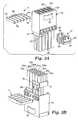
- FIGS 2A and 2Bshow isometric views of the housing made from insulating material.
- Housing 10contains a generally v ertically-extending front w all 12 having interior surface 12a and exterior surface 12b.
- the front wallis formed to include a plurality of pin insertion apertures 12c arranged in rows and columns. In between the pin insertion apertures are blade insertion apertures 12d and supports 12e, which are disposed on interior surface 12a.
- the supportsaid in the alignment of the terminated cable assemblies described below.
- the housingalso includes pair of laterally-extending top and bottom walls 14 and 16 respectively, each optionally having a series of guides 14a and 16a. Side walls 18, with guides 18a, also form part of the housing.
- a headeris disposed on at least one of the top and bottom walls.
- a latching device 22i.e., a device in which mating mechanical parts engage to fasten but usually not to lock the header to the housing.
- Figures 3A and 3Bshow two different views of the carrier with terminated cable assemblies 30 mounted therein. These figures best show how means for securing and means for managing the terminated cable assemblies (i.e., the combination of clip 4 and cross-clip 6) function in conjunction with housing 10.
- the cliphas a plurality of ribs 4b extending laterally from back 4a, optional snapping features 4c on the end ribs and optional finger tab 4d on at least one side of the back to aid in the assembly and disassembly of the clip from the carrier clip holes 20 disposed in housing 10.
- the number of ribs 4bmatches the number of holes 20, although it is within the scope of the present invention to have a different number of ribs than holes, e.g., less ribs than holes.
- the length of the clip, as measured from back 4a to the end of ribs 4bis about the same length as that of the housing from the top wall 14 to the bottom wall 16 such that when the clip is attached to top wall 14 of the housing through holes 20, snapping feature 4c extends from bottom wall 16.
- the clipis typically an integrally molded piece of insulating material.
- Cross-clip 6includes a plurality of organizers 6b, and at least one end 6c . Located on end 6c is interference shoulder 6d, and optionally a plurality of interlocking apertures 6e. If two ends 6c are used, the second end may or may not include the interference shoulder or the interlocking apertures.
- the width of the cross-clip, as measured from one end to the other, or if two ends are not used, from one end to the last organizer furthest away from the end,is about the same as the distance from top wall 14 to bottom wall 16 of the housing.
- the cross-clipslides over the terminated cable assemblies 30 until interference shoulder 6d on end 6c abuts top wall 14 of the housing.
- ribs 6bsegregates rows 30a, 30b, 30c, 30d, and 30e from one another and the interlocking apertures, if used, are aligned with carrier clip holes 20 on the housing 10. If two ends 6c are used, the interference shoulder on the second end would abut bottom wall 16 of the housing.
- each of the four internal rib 4i.e., excluding the two end ribs
- Figure 3Bshows an array of five columns and five rows of terminated cable assemblies, any number of columns and rows can be used and the designation of the column and the row are arbitrary, i.e., a column can be a row.
- Figure 4shows one exemplary embodiment of a terminated cable assembly that can be used in conjunction with the carrier.
- Terminated cable assembly 30are conventional in design, except that each termination device 34 includes contact beam 36 on the top surface 34b for making electrical contact with the ground blades in the header, discussed below.
- Electrical cable 32is attached to termination device 34 through the use of solder openings 38.
- the type of electrical cable used in this inventioncan be a single wire cable (e.g. single coaxial or single twin axial) or a multiple wire cable (e.g. multiple coaxial or multiple twin axial or twisted pair cables).
- the terminated cable assembliesare inserted into housing 10 such that front face 34a of termination devices 34 abuts interior surface 12a of the front vertical wall of the housing 10.
- Female contacts 40lies along the longitudinal axis of the termination device and aligns with pin insertion apertures 12c of the front vertical wall of the housing. Thus, a portion of the termination device rests on support 12d. Top wall guide 14a and bottom wall guide 16a also help position the first and last termination device in the column.
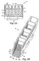
- FIG. 5shows an exemplary pin header 60 that can be used in the present invention.
- the headerincludes vertical front wall 62, having interior surface 62a and exterior surface 62b, and laterally extending top and bottom walls 64 and 66 respectively.
- the vertical front wallis formed to include a plurality of pin insertion windows for signal pins 70 and a plurality of blade insertion windows for ground blades 68.
- the headeris mated with the carrier 2 such that exterior surface 62b of the header is in contact with exterior surface 12b of the housing so that signal pins 70 and ground blades 68 slide through pin insertion apertures 12c and blade insertion apertures 12d respectively to mate with female contacts 40 and ground contacts 36 respectively of the terminated cable assembly.
- Another useful pin headerthat can be used in the present invention is disclosed in US Patent No. 6,146,202 (Ramey et al. ), which is hereby incorporated by reference in its entirety.
- FIG. 4shows that termination device 34 contains contact beam 36, it is within the scope of the present invention to place the contact beam on the ground blade 68 in the header or on both termination device 34 and ground blade 68.
- Figure 6shows a partially assembled high speed connector used in conjunction with printed circuit board (PCB) 80.
- terminated cable assemblies 30are attached to one side of the carrier while header 60 is attached on the other side.
- the headerfurther includes means for fastening to the carrier.
- the means for fasteningis retaining clip 72 having tab 72a and clip end 72b. In use, tab 72a of the retaining clip slides under latching device 22 on housing 10 to hold the header to the carrier.
- means for fastening the header to the carrieris done through the use of sufficiently high friction force between the ground blades in the header to the termination device.
- the headercould be fastened to the carrier through sufficiently high friction force between the signal pins in the header and the female contacts in the terminated cable assemblies.
- FIG. 6shows several retaining clips 72 used with several latching devices 22 on the top wall of the housing, similar retaining clips and latching device combinations can be used on the bottom wall of the housing. Also, any number of header and carrier combinations can be used together even though two are shown.
- PCB 80On PCB 80 is mounted a plurality of connector modules 90 assembled in socket 92. The PCB, connector module, and socket are all in electrical communication the each other. If desired, optional male guides 94 can be added to socket 92 to help guide the socket into the header.
- the headerwould contain complimentary female guides (not shown).
- Useful connector modules and socketsare disclosed in US Patent No. 6,146,202 (Ramey et al. ). As one skilled in the art will recognize, to complete the electrical circuit, the header/carrier/terminated cable assembly is mated to the socket. Although the above description recites a particular sequence to assemble the high speed connector, one skilled in the art will recognize that different assembly sequences can be used.
Landscapes
- Details Of Connecting Devices For Male And Female Coupling (AREA)
- Connector Housings Or Holding Contact Members (AREA)
- Coupling Device And Connection With Printed Circuit (AREA)
- Paper (AREA)
- Mechanical Coupling Of Light Guides (AREA)
Abstract
Description
- The present invention relates to a high speed connector. In particular, the present invention relates to a connector that provides for controlled impedance and allows for quick and easy replacement of components.
- Interconnection of integrated circuits to other circuit boards, cables or electronic devices is known in the art. Such interconnections typically have not been difficult to form, especially when the circuit switching speeds (also referred to as signal transmission times) have been slow when compared to the length of time required for a signal to propagate through a conductor in the interconnect or in the printed circuit board. As signal transmission times continue to increase with modem integrated circuits and related computer technology, the design and manufacture of interconnects that can perform satisfactorily has grown more difficult.
- There is a growing need to design and manufacture electrical interconnects with closely controlled electrical characteristics to achieve satisfactory control of the signal integrity. The extent to which the electrical characteristics (such as impedance) can be controlled depends on the switching speed of the circuit, i.e., the faster the circuit switching speed, the greater the importance of providing an accurately controlled impedance within the interconnect.
- Connectors have been developed to provide the necessary impedance control for high speed circuits, i.e., circuits with a transmission frequency of at least 5 GHz. Although many of these connectors are useful, there is still a need in the art for different and more economical connector designs that provide for easy component replacements.
- The present invention pertains to a connector assembly designed to provide controlled impedance to maintain signal and ground integrity, and to allow for quick and easy assembly and disassembly for replacing components or for modifying or upgrading with different components. In this way, the present invention provides economic advantages to the consumer in that only the selected component in the connector assembly needs to be replaced instead of replacing the entire assembly.
- In one aspect, the present invention provides a carrier for use with an electrical connector assembly. The carrier comprises an insulating housing and means for securing the terminated cable assemblies. Optionally, the carrier further comprises a means for managing the terminated cable assemblies. In one exemplary embodiment, means for securing and means for managing the terminated cable assemblies are integrated. The housing includes a front vertical wall, laterally extending top and bottom walls, at least one set of carrier clip holes disposed on at least one of the top and bottom walls, and means for fastening a header to the housing.
- In another aspect, the present invention provides another carrier for use with an electrical connector assembly. The carrier comprises an insulating housing having a front vertical wall and laterally extending top and bottom walls. The front vertical wall has an interior and an exterior surface. The housing also has at least one latch and at least one set of carrier clip holes, both disposed on at least one of the top and bottom walls. The carrier further comprises at least one clip having a back and plurality of ribs extending from the back. The clip is disposed in the housing such that the ribs mate with the carrier clip holes in the housing. In another exemplary embodiment, the carrier further comprises at least one cross-clip having at least one interference shoulder and a plurality of organizers. The cross-clip is disposed in the housing such that the interference shoulder rests against at least one of the top and bottom walls of the housing.
- As discussed in detail below, the header, with its plurality of signal pins and ground blades, tends to be susceptible to damage. In the event that a header does become damaged or needs to be upgraded or modified, the connector assembly can be quickly disassembled so the header can be replaced. And, the connector assembly has been designed to allow for quick and easy replacement of the shielded electrical cable, if desired.
- The above summary of the present invention is not intended to describe each disclosed embodiment or every implementation of the present invention. The Figures and detailed description that follow below more particularly exemplify illustrative embodiments.
Figure 1 is an isometric view of an exemplary carrier in accordance with one aspect of the present invention;Figures 2A and 2B are isometric views of an exemplary housing used in the carrier in accordance with another aspect of the present invention;Figures 3A and 3B are isometric views of a carrier containing terminated cable assemblies in accordance with another aspect of the present invention;Figure 4 is an isometric view of an exemplary terminated cable assembly that can be used in conjunction with the present invention;Figure 5 is an isometric view of an exemplary header that can be used in conjunction with the present invention; andFigure 6 is a perspective view of an exemplary high speed electrical connector assembly in a partially unassembled stage, in accordance with another aspect of the present invention.- These figures are idealized, not drawn to scale and are intended only for illustrative purposes.
Figure1 shows one embodiment ofcarrier 2 havinghousing 10 and means for securing and managing terminated cable assemblies, which can be mechanical devices that are used to hold and to maintain order in the terminated cable assemblies to minimizing their entanglement.Figure1 shows one means for securing and managing the terminated cable assemblies, which includesclip 4 andcross-clip 6. The carrier can be made by any conventional means, such as by injection molding.Figures2A and2B show isometric views of the housing made from insulating material.Housing 10 contains a generally v ertically-extending front w all12 havinginterior surface 12a andexterior surface 12b. The front wall is formed to include a plurality ofpin insertion apertures 12c arranged in rows and columns. In between the pin insertion apertures areblade insertion apertures 12d and supports12e, which are disposed oninterior surface 12a. The supports aid in the alignment of the terminated cable assemblies described below. The housing also includes pair of laterally-extending top andbottom walls guides Side walls 18, withguides 18a, also form part of the housing. On at least one of the laterally-extending top and bottom walls, there are a plurality ofcarrier clip holes 20 to accommodate means for securing and managing terminated cable assemblies. Also means to fasten a header is disposed on at least one of the top and bottom walls. As shown inFigure2A , one means to fasten the header to the housing is alatching device 22, i.e., a device in which mating mechanical parts engage to fasten but usually not to lock the header to the housing.Figures3A and3B show two different views of the carrier with terminatedcable assemblies 30 mounted therein. These figures best show how means for securing and means for managing the terminated cable assemblies (i.e., the combination ofclip 4 and cross-clip6) function in conjunction withhousing 10. The clip has a plurality ofribs 4b extending laterally fromback 4a, optional snapping features4c on the end ribs andoptional finger tab 4d on at least one side of the back to aid in the assembly and disassembly of the clip from thecarrier clip holes 20 disposed inhousing 10. In one embodiment, the number ofribs 4b matches the number ofholes 20, although it is within the scope of the present invention to have a different number of ribs than holes, e.g., less ribs than holes. In one embodiment, wheresnapping feature 4c is used, the length of the clip, as measured fromback 4a to the end ofribs 4b is about the same length as that of the housing from thetop wall 14 to thebottom wall 16 such that when the clip is attached totop wall 14 of the housing throughholes 20,snapping feature 4c extends frombottom wall 16. The clip is typically an integrally molded piece of insulating material.- Cross-clip6 includes a plurality of
organizers 6b, and at least oneend 6c. Located onend 6c isinterference shoulder 6d, and optionally a plurality of interlockingapertures 6e. If twoends 6c are used, the second end may or may not include the interference shoulder or the interlocking apertures. The width of the cross-clip, as measured from one end to the other, or if two ends are not used, from one end to the last organizer furthest away from the end, is about the same as the distance fromtop wall 14 tobottom wall 16 of the housing. - As shown in
Figure3B , the cross-clip slides over the terminatedcable assemblies 30 untilinterference shoulder 6d onend 6c abutstop wall 14 of the housing. In this case,ribs 6b segregatesrows housing 10. If two ends6c are used, the interference shoulder on the second end would abutbottom wall 16 of the housing. Once the cross-clip has been installed so that the interference shoulder stops against at least one of the top or bottom walls,clip 4 is then installed such thatribs 4b slide intoholes 20 on the housing and back4a of the clip rests ontop wall 14. If two clips are used, the second clip rests onbottom wall 16 of the housing. As the clip slides intoholes 20, it also slides into interlockingapertures 6e (if used) on the cross-clip, thereby holding it in place. Each of the four internal rib4 (i.e., excluding the two end ribs) of the clip separatescolumns Figure3B shows an array of five columns and five rows of terminated cable assemblies, any number of columns and rows can be used and the designation of the column and the row are arbitrary, i.e., a column can be a row. With this design, a user can easily replace terminated cable assembly by removingclip 4 andcross-clip 6 and then removing the individual cable. Figure4 shows one exemplary embodiment of a terminated cable assembly that can be used in conjunction with the carrier.Terminated cable assembly 30 are conventional in design, except that eachtermination device 34 includescontact beam 36 on thetop surface 34b for making electrical contact with the ground blades in the header, discussed below.Electrical cable 32 is attached totermination device 34 through the use ofsolder openings 38. The type of electrical cable used in this invention can be a single wire cable (e.g. single coaxial or single twin axial) or a multiple wire cable (e.g. multiple coaxial or multiple twin axial or twisted pair cables). In use, the terminated cable assemblies are inserted intohousing 10 such thatfront face 34a oftermination devices 34 abutsinterior surface 12a of the front vertical wall of thehousing 10.Female contacts 40 lies along the longitudinal axis of the termination device and aligns withpin insertion apertures 12c of the front vertical wall of the housing. Thus, a portion of the termination device rests onsupport 12d.Top wall guide 14a andbottom wall guide 16a also help position the first and last termination device in the column.Figure5 shows anexemplary pin header 60 that can be used in the present invention. The header includes verticalfront wall 62, havinginterior surface 62a andexterior surface 62b, and laterally extending top andbottom walls ground blades 68. In use, the header is mated with thecarrier 2 such thatexterior surface 62b of the header is in contact withexterior surface 12b of the housing so that signal pins70 andground blades 68 slide throughpin insertion apertures 12c andblade insertion apertures 12d respectively to mate withfemale contacts 40 andground contacts 36 respectively of the terminated cable assembly. Another useful pin header that can be used in the present invention is disclosed inUS Patent No. 6,146,202 (Ramey et al. ), which is hereby incorporated by reference in its entirety.- Although
Figure4 shows thattermination device 34 containscontact beam 36, it is within the scope of the present invention to place the contact beam on theground blade 68 in the header or on bothtermination device 34 andground blade 68. Figure6 shows a partially assembled high speed connector used in conjunction with printed circuit board (PCB)80. As shown, terminatedcable assemblies 30 are attached to one side of the carrier whileheader 60 is attached on the other side. The header further includes means for fastening to the carrier. In this particular embodiment, the means for fastening is retainingclip 72 havingtab 72a andclip end 72b. In use,tab 72a of the retaining clip slides under latchingdevice 22 onhousing 10 to hold the header to the carrier.- In another embodiment, means for fastening the header to the carrier (having the terminated cable assemblies attached) is done through the use of sufficiently high friction force between the ground blades in the header to the termination device. Alternatively or in addition to this friction force, the header could be fastened to the carrier through sufficiently high friction force between the signal pins in the header and the female contacts in the terminated cable assemblies.
- In the event that a header is damaged or needs to be upgraded or modified, it can be replaced by spreading clip ends72b apart, removing the existing header, and installing a new header. In this way, the present invention provides an economical and user friendly design that allows for replacement of headers. Although
Figure6 shows several retainingclips 72 used withseveral latching devices 22 on the top wall of the housing, similar retaining clips and latching device combinations can be used on the bottom wall of the housing. Also, any number of header and carrier combinations can be used together even though two are shown. OnPCB 80 is mounted a plurality ofconnector modules 90 assembled insocket 92. The PCB, connector module, and socket are all in electrical communication the each other. If desired, optional male guides94 can be added tosocket 92 to help guide the socket into the header. In this case, the header would contain complimentary female guides (not shown). Useful connector modules and sockets are disclosed inUS Patent No. 6,146,202 (Ramey et al. ). As one skilled in the art will recognize, to complete the electrical circuit, the header/carrier/terminated cable assembly is mated to the socket. Although the above description recites a particular sequence to assemble the high speed connector, one skilled in the art will recognize that different assembly sequences can be used.
Claims (12)
- A carrier (2) for use with an electrical connector assembly, said carrier (2) comprising:(a.) an insulating housing (10) having a front vertical wall (12) and laterally extending top and bottom walls, at least one latch (22), and at least one set of carrier clip holes (20) disposed on at least one of said top and bottom walls,(b.) at least one clip having plurality ribs extending from a back; said clip disposed in said housing such that said ribs mate with said carrier clip holes in said housing,wherein said front vertical wall includes a plurality of pin insertion apertures (12c) disposed between rows and columns of blade insertion apertures (12d) and has interior (12a) and exterior surfaces (12b);
- The carrier of claim 1 further comprising at least one cross-clip having at least one end and a plurality of ribs wherein said end of said cross-clip has at least one interference shoulder and at least one interlocking aperture and wherein said cross-clip is disposed in said housing such that said interference shoulder rests against at least one of said top and bottom walls of said housing.
- An electrical connector assembly comprising:(a) the carrier of claim 1 or claim 2; and(b) a plurality of terminated cable assemblies comprising an electrical cable attached to a termination device, wherein said termination device has a ground contact beam disposed on its top surface, a front face, and at least one female contact lying parallel to the longitudinal axis of the terminated cable assemblies,wherein said terminated cable assemblies is disposed in said carrier such that said front face of said termination device is in contact with said internal surface of said housing.
- The electrical connector assembly of claim 3 further comprising a header, said header comprising:(a) a front vertical wall having an interior surface and an exterior surface; and(b) an array of signal pins disposed between rows and columns of ground blades, wherein said signal pins and ground blades extend through said front vertical wall, andwherein said header is disposed in said carrier such that said exterior surface of said header abuts said exterior surface of said carrier and said signal pins in said header advance through said front vertical wall of said housing to reside in said female contacts of said terminated cable assembly and said ground blades in said header advance through said front vertical wall of said housing to contact said ground contact on said termination device.
- The electrical connector assembly of claim 4 further comprising means for fastening said carrier to said header.
- The electrical connector assembly of claim 5 wherein said means for fastening comprises a latching device disposed on at least one of said top or bottom wall of said housing of said carrier and a retaining clip disposed on at least one of said top and bottom walls of said header.
- The electrical connector assembly of claim 6 further comprising:(a) a socket mated to said interior surface of said vertical wall of said header;(b) a plurality of connector modules attached to said socket; and(c) a printed circuit board attached to said connector modules, wherein said printed circuit board, connector modules, socket, header, carrier, and terminated cable assembly are in electrical communication.
- An electrical connector assembly comprising:(a) the carrier of claim 1 or 2;(b) a plurality of terminated cable assemblies comprising an electrical cable attached to a termination device, wherein said termination device has a front face and at least one female contact lying parallel to the longitudinal axis of the terminated cable assemblies, and wherein said terminated cable assemblies is disposed in said carrier such that said front face of said termination device is in contact with said internal surface of said housing.
- The electrical connector assembly of claim 8 further comprising a header, said header comprising:(a) a front vertical wall having an interior surface and an exterior surface; and(b) an array of signal pins disposed between rows and columns of ground blades having a contact beam, wherein said signal pins and said ground blades extend through said front vertical wall, andwherein said header is disposed in said carrier such that said exterior surface of said header abuts said exterior surface of said carrier and said signal pins in said header advance through said front vertical wall of said housing to reside in said female contacts of said terminated cable assembly and said ground blades in said header advance through said front vertical wall of said housing to contact said termination device.
- The electrical connector assembly of claim 9 further comprising:(a) a socket mated to said interior surface of said vertical wall of said header;(b) a plurality of connector modules attached to said socket; and(c) a printed circuit board attached to said connector modules, wherein said printed circuit board, connector modules, socket, header, carrier, and terminated cable assembly are in electrical communication.
- The electrical assembly of claim 3 further comprising a header, said header comprising:(a) a front vertical wall having an interior surface and an exterior surface; and(b) an array of signal pins disposed between rows and columns of ground blades having a contact beam, wherein said signal pins and said ground blades extend through said front vertical wall,wherein said header is disposed in said carrier such that said exterior surface of said header abuts said exterior surface of said carrier and said signal pins in said header advance through said front vertical wall of said housing to reside in said female contacts of said terminated cable assembly and said ground blades in said header advance through said front vertical wall of said housing to contact said ground contact beam on said termination device.
- The electrical connector assembly of claim 11 further comprising:(a) a socket mated to said interior surface of said vertical wall of said header;(b) a plurality of connector modules attached to said socket; and(c) a printed circuit board attached to said connector modules, wherein said printed circuit board, connector modules, socket, header, carrier, and terminated cable assembly are in electrical communication.
Applications Claiming Priority (3)
| Application Number | Priority Date | Filing Date | Title |
|---|---|---|---|
| US317690 | 1989-03-01 | ||
| US10/317,690US6780069B2 (en) | 2002-12-12 | 2002-12-12 | Connector assembly |
| PCT/US2003/034018WO2004055946A1 (en) | 2002-12-12 | 2003-10-28 | Connector assembly |
Publications (2)
| Publication Number | Publication Date |
|---|---|
| EP1570549A1 EP1570549A1 (en) | 2005-09-07 |
| EP1570549B1true EP1570549B1 (en) | 2010-01-06 |
Family
ID=32506192
Family Applications (1)
| Application Number | Title | Priority Date | Filing Date |
|---|---|---|---|
| EP03779307AExpired - LifetimeEP1570549B1 (en) | 2002-12-12 | 2003-10-28 | Connector assembly |
Country Status (8)
| Country | Link |
|---|---|
| US (1) | US6780069B2 (en) |
| EP (1) | EP1570549B1 (en) |
| JP (1) | JP4362448B2 (en) |
| CN (1) | CN100481633C (en) |
| AT (1) | ATE454729T1 (en) |
| AU (1) | AU2003284989A1 (en) |
| DE (1) | DE60330907D1 (en) |
| WO (1) | WO2004055946A1 (en) |
Families Citing this family (51)
| Publication number | Priority date | Publication date | Assignee | Title |
|---|---|---|---|---|
| JP2004273154A (en)* | 2003-03-05 | 2004-09-30 | Yazaki Corp | Joint connector and terminal |
| DE10310502A1 (en)* | 2003-03-11 | 2004-09-23 | Molex Inc., Lisle | Earthed electrical connector for GHz signal frequency range, has earthing terminal provided with at least 2 mechanically coupled electrical contacts |
| WO2005053102A2 (en)* | 2003-11-21 | 2005-06-09 | Ohio Associated Enterprises Llc | Cable assembly and method of making |
| GB2416927A (en)* | 2004-07-29 | 2006-02-08 | Itt Mfg Enterprises Inc | Cable Clamp |
| DE102005039090A1 (en)* | 2005-08-06 | 2007-02-08 | Behr Gmbh & Co. Kg | Assembly support system |
| US20070141871A1 (en)* | 2005-12-19 | 2007-06-21 | 3M Innovative Properties Company | Boardmount header to cable connector assembly |
| US7553187B2 (en)* | 2006-01-31 | 2009-06-30 | 3M Innovative Properties Company | Electrical connector assembly |
| US7731528B2 (en)* | 2006-01-31 | 2010-06-08 | 3M Innovative Properties Company | Electrical termination device |
| US7651355B2 (en)* | 2006-06-30 | 2010-01-26 | 3M Innovative Properties Company | Floating panel mount connection system |
| CN101517833B (en)* | 2006-09-14 | 2011-06-22 | 3M创新有限公司 | Electrical connector assembly |
| JP4760683B2 (en)* | 2006-11-20 | 2011-08-31 | 住友電装株式会社 | connector |
| US7744403B2 (en)* | 2006-11-29 | 2010-06-29 | 3M Innovative Properties Company | Connector for electrical cables |
| US7484989B2 (en)* | 2006-11-29 | 2009-02-03 | Ohio Associated Enterprises, Llc | Low friction cable assembly latch |
| US7445471B1 (en)* | 2007-07-13 | 2008-11-04 | 3M Innovative Properties Company | Electrical connector assembly with carrier |
| US8007308B2 (en)* | 2007-10-17 | 2011-08-30 | 3M Innovative Properties Company | Electrical connector assembly |
| WO2009055242A2 (en)* | 2007-10-19 | 2009-04-30 | 3M Innovative Properties Company | Electrical connector assembly |
| US7651374B2 (en)* | 2008-06-10 | 2010-01-26 | 3M Innovative Properties Company | System and method of surface mount electrical connection |
| US7744414B2 (en)* | 2008-07-08 | 2010-06-29 | 3M Innovative Properties Company | Carrier assembly and system configured to commonly ground a header |
| CN201285845Y (en)* | 2008-08-05 | 2009-08-05 | 富士康(昆山)电脑接插件有限公司 | Electric connector |
| US20100068944A1 (en)* | 2008-09-18 | 2010-03-18 | 3M Innovative Properties Company | Electrical connector and circuit board interconnect |
| US9011177B2 (en) | 2009-01-30 | 2015-04-21 | Molex Incorporated | High speed bypass cable assembly |
| US8062065B2 (en)* | 2009-09-15 | 2011-11-22 | Tyco Electronics Corporation | Connector assembly having a stabilizer |
| US8475177B2 (en)* | 2010-01-20 | 2013-07-02 | Ohio Associated Enterprises, Llc | Backplane cable interconnection |
| WO2011094656A2 (en) | 2010-02-01 | 2011-08-04 | 3M Innovative Properties Company | Electrical connector and assembly |
| TWM430018U (en)* | 2010-03-19 | 2012-05-21 | Molex Inc | Cable connector and connector circuit board spacer |
| CN102891390A (en)* | 2011-07-20 | 2013-01-23 | 贵州航天电器股份有限公司 | Combined electric connector plug |
| US8435074B1 (en)* | 2011-11-14 | 2013-05-07 | Airborn, Inc. | Low-profile right-angle electrical connector assembly |
| US8784122B2 (en) | 2011-11-14 | 2014-07-22 | Airborn, Inc. | Low-profile right-angle electrical connector assembly |
| US9496667B2 (en) | 2012-07-23 | 2016-11-15 | Molex, Llc | Electrical harness connector system with differential pair connection link |
| US9142921B2 (en) | 2013-02-27 | 2015-09-22 | Molex Incorporated | High speed bypass cable for use with backplanes |
| CN103236609B (en)* | 2013-04-10 | 2015-08-26 | 中航光电科技股份有限公司 | Small size electric coupler component and plug and socket thereof |
| CN105580210B (en) | 2013-09-04 | 2017-07-07 | 莫列斯有限公司 | Connector system with bypass cable |
| US9246286B2 (en)* | 2013-09-25 | 2016-01-26 | Virginia Panel Corporation | High speed data module for high life cycle interconnect device |
| KR101944361B1 (en)* | 2014-01-06 | 2019-02-01 | 삼성전자주식회사 | Connector and refrigerator including the same |
| EP2991172B1 (en)* | 2014-08-27 | 2021-01-13 | TE Connectivity Germany GmbH | Vehicular cable assembly |
| WO2016048374A1 (en)* | 2014-09-26 | 2016-03-31 | Hewlett Packard Enterprise Development Lp | Receptacle for connecting a multi-lane or one-lane cable |
| KR102120813B1 (en) | 2015-01-11 | 2020-06-17 | 몰렉스 엘엘씨 | Circuit board bypass assembly and components therefor |
| WO2016112384A1 (en) | 2015-01-11 | 2016-07-14 | Molex, Llc | Wire to board connectors suitable for use in bypass routing assemblies |
| US10193277B2 (en) | 2015-02-18 | 2019-01-29 | Hewlett Packard Enterprise Development Lp | Pull-tabs for disengaging a cable assembly from a receptacle |
| US10741963B2 (en) | 2015-02-27 | 2020-08-11 | Hewlett Packard Enterprise Development Lp | Cable assembly with conjoined one-lane cable assemblies |
| US10389068B2 (en) | 2015-04-29 | 2019-08-20 | Hewlett Packard Enterprise Development Lp | Multiple cable housing assembly |
| WO2016179263A1 (en) | 2015-05-04 | 2016-11-10 | Molex, Llc | Computing device using bypass assembly |
| US10424856B2 (en) | 2016-01-11 | 2019-09-24 | Molex, Llc | Routing assembly and system using same |
| TWI625010B (en) | 2016-01-11 | 2018-05-21 | Molex Llc | Cable connector assembly |
| US10673169B2 (en) | 2016-01-14 | 2020-06-02 | J.S.T. Corporation | Method of operating MSL connector series |
| TWI597896B (en) | 2016-01-19 | 2017-09-01 | Molex Llc | Integrated routing components |
| DE102016104267B4 (en)* | 2016-03-09 | 2017-10-19 | Harting Electric Gmbh & Co. Kg | Current measurement in the insulating body |
| CN105742877B (en)* | 2016-04-18 | 2018-05-29 | 欧品电子(昆山)有限公司 | Mixed type pin connector |
| JP7076265B2 (en)* | 2018-04-03 | 2022-05-27 | スリーエム イノベイティブ プロパティズ カンパニー | connector |
| JP7318311B2 (en)* | 2019-05-29 | 2023-08-01 | 株式会社オートネットワーク技術研究所 | female connector and connector |
| JP7389407B2 (en)* | 2020-03-09 | 2023-11-30 | 株式会社オートネットワーク技術研究所 | card edge connector |
Family Cites Families (21)
| Publication number | Priority date | Publication date | Assignee | Title |
|---|---|---|---|---|
| JPS62188186A (en)* | 1986-02-14 | 1987-08-17 | 日産自動車株式会社 | Double locking mechanism for composite connector terminals |
| JPH02501870A (en) | 1986-10-03 | 1990-06-21 | ミネソタ マイニング アンド マニユフアクチユアリング カンパニー | Shielded and grounded connector system for coaxial cables |
| US4889500A (en) | 1988-05-23 | 1989-12-26 | Burndy Corporation | Controlled impedance connector assembly |
| EP0511649B1 (en)* | 1991-04-30 | 1996-11-13 | Yazaki Corporation | Connector |
| GB2255863B (en) | 1991-05-17 | 1995-05-03 | Minnesota Mining & Mfg | Connector for coaxial cables |
| US5125854A (en) | 1991-07-16 | 1992-06-30 | Molex Incorporated | Modular electrical connector |
| US5169347A (en) | 1991-10-15 | 1992-12-08 | Molex Incorporated | Slip-off electrical connector header |
| JP2581476Y2 (en)* | 1993-04-13 | 1998-09-21 | 住友電装株式会社 | connector |
| JP2725756B2 (en)* | 1993-09-01 | 1998-03-11 | 矢崎総業株式会社 | Connector with terminal lock |
| SE508781C2 (en) | 1994-06-10 | 1998-11-02 | Ericsson Telefon Ab L M | A plug- |
| JPH08106944A (en)* | 1994-10-03 | 1996-04-23 | Tokai Rika Co Ltd | Electric connector and housing of this electric connector |
| US5788519A (en) | 1995-05-02 | 1998-08-04 | Yazaki Corporation | Waterproof grounding connector and method of assembling same |
| JP3296707B2 (en)* | 1995-12-22 | 2002-07-02 | 古河電気工業株式会社 | Connector with terminal stopper |
| JP3175575B2 (en)* | 1996-02-14 | 2001-06-11 | 住友電装株式会社 | connector |
| US5766036A (en) | 1996-10-11 | 1998-06-16 | Molex Incorporated | Impedance matched cable assembly having latching subassembly |
| TW338561U (en) | 1997-02-25 | 1998-08-11 | Hon Hai Prec Ind Co Ltd | A connector with replaceable leads |
| JP3301597B2 (en) | 1997-09-30 | 2002-07-15 | タイコエレクトロニクスアンプ株式会社 | Coaxial connector and coaxial connector assembly using the same |
| US6146202A (en)* | 1998-08-12 | 2000-11-14 | Robinson Nugent, Inc. | Connector apparatus |
| US6116926A (en)* | 1999-04-21 | 2000-09-12 | Berg Technology, Inc. | Connector for electrical isolation in a condensed area |
| JP3638095B2 (en)* | 1999-06-11 | 2005-04-13 | 矢崎総業株式会社 | Terminal incomplete insertion detection structure |
| US6368120B1 (en) | 2000-05-05 | 2002-04-09 | 3M Innovative Properties Company | High speed connector and circuit board interconnect |
- 2002
- 2002-12-12USUS10/317,690patent/US6780069B2/ennot_activeExpired - Lifetime
- 2003
- 2003-10-28DEDE60330907Tpatent/DE60330907D1/ennot_activeExpired - Lifetime
- 2003-10-28AUAU2003284989Apatent/AU2003284989A1/ennot_activeAbandoned
- 2003-10-28CNCNB2003801057717Apatent/CN100481633C/ennot_activeExpired - Fee Related
- 2003-10-28ATAT03779307Tpatent/ATE454729T1/ennot_activeIP Right Cessation
- 2003-10-28EPEP03779307Apatent/EP1570549B1/ennot_activeExpired - Lifetime
- 2003-10-28WOPCT/US2003/034018patent/WO2004055946A1/enactiveApplication Filing
- 2003-10-28JPJP2004560301Apatent/JP4362448B2/ennot_activeExpired - Fee Related
Also Published As
| Publication number | Publication date |
|---|---|
| JP4362448B2 (en) | 2009-11-11 |
| AU2003284989A1 (en) | 2004-07-09 |
| US20040115997A1 (en) | 2004-06-17 |
| EP1570549A1 (en) | 2005-09-07 |
| CN1726621A (en) | 2006-01-25 |
| US6780069B2 (en) | 2004-08-24 |
| DE60330907D1 (en) | 2010-02-25 |
| ATE454729T1 (en) | 2010-01-15 |
| JP2006510183A (en) | 2006-03-23 |
| CN100481633C (en) | 2009-04-22 |
| WO2004055946A1 (en) | 2004-07-01 |
Similar Documents
| Publication | Publication Date | Title |
|---|---|---|
| EP1570549B1 (en) | Connector assembly | |
| JP6990737B2 (en) | High speed connector system | |
| US11327248B2 (en) | Optical assemblies with managed connectivity | |
| US20150194751A1 (en) | Backplane or midplane communication system and electrical connector | |
| US7539018B2 (en) | Heat sink retaining clip for an electrical connector assembly | |
| US7090523B2 (en) | Release mechanism for transceiver module assembly | |
| US7591683B2 (en) | Contact terminal, extender with improved ground contact, and method for making the extender | |
| US7909646B2 (en) | Electrical carrier assembly and system of electrical carrier assemblies | |
| US20070141871A1 (en) | Boardmount header to cable connector assembly | |
| US20080020615A1 (en) | Electrical termination device | |
| CN113574748A (en) | Connector and contact for single twisted conductor pairs | |
| KR20010095054A (en) | Adapter usable with an electronic interconnect for high speed signal and data transmission | |
| JP2013508918A (en) | Managed electrical connection system | |
| US7381087B2 (en) | Connector assembly | |
| US8007308B2 (en) | Electrical connector assembly | |
| US20080293296A1 (en) | Modular mounting sleeve for jack | |
| US7651359B2 (en) | Electrical connector assembly | |
| US6830487B2 (en) | Pin jack for a digital switching cross-connect module | |
| US20230262921A1 (en) | Floating data communication module | |
| KR20000015116U (en) | Auxiliary connector |
Legal Events
| Date | Code | Title | Description |
|---|---|---|---|
| PUAI | Public reference made under article 153(3) epc to a published international application that has entered the european phase | Free format text:ORIGINAL CODE: 0009012 | |
| 17P | Request for examination filed | Effective date:20050524 | |
| AK | Designated contracting states | Kind code of ref document:A1 Designated state(s):AT BE BG CH CY CZ DE DK EE ES FI FR GB GR HU IE IT LI LU MC NL PT RO SE SI SK TR | |
| AX | Request for extension of the european patent | Extension state:AL LT LV MK | |
| DAX | Request for extension of the european patent (deleted) | ||
| GRAJ | Information related to disapproval of communication of intention to grant by the applicant or resumption of examination proceedings by the epo deleted | Free format text:ORIGINAL CODE: EPIDOSDIGR1 | |
| GRAP | Despatch of communication of intention to grant a patent | Free format text:ORIGINAL CODE: EPIDOSNIGR1 | |
| GRAP | Despatch of communication of intention to grant a patent | Free format text:ORIGINAL CODE: EPIDOSNIGR1 | |
| GRAS | Grant fee paid | Free format text:ORIGINAL CODE: EPIDOSNIGR3 | |
| GRAA | (expected) grant | Free format text:ORIGINAL CODE: 0009210 | |
| AK | Designated contracting states | Kind code of ref document:B1 Designated state(s):AT BE BG CH CY CZ DE DK EE ES FI FR GB GR HU IE IT LI LU MC NL PT RO SE SI SK TR | |
| REG | Reference to a national code | Ref country code:GB Ref legal event code:FG4D | |
| REG | Reference to a national code | Ref country code:CH Ref legal event code:EP | |
| REG | Reference to a national code | Ref country code:IE Ref legal event code:FG4D | |
| REF | Corresponds to: | Ref document number:60330907 Country of ref document:DE Date of ref document:20100225 Kind code of ref document:P | |
| REG | Reference to a national code | Ref country code:NL Ref legal event code:VDEP Effective date:20100106 | |
| PG25 | Lapsed in a contracting state [announced via postgrant information from national office to epo] | Ref country code:SI Free format text:LAPSE BECAUSE OF FAILURE TO SUBMIT A TRANSLATION OF THE DESCRIPTION OR TO PAY THE FEE WITHIN THE PRESCRIBED TIME-LIMIT Effective date:20100106 | |
| PG25 | Lapsed in a contracting state [announced via postgrant information from national office to epo] | Ref country code:AT Free format text:LAPSE BECAUSE OF FAILURE TO SUBMIT A TRANSLATION OF THE DESCRIPTION OR TO PAY THE FEE WITHIN THE PRESCRIBED TIME-LIMIT Effective date:20100106 | |
| PG25 | Lapsed in a contracting state [announced via postgrant information from national office to epo] | Ref country code:PT Free format text:LAPSE BECAUSE OF FAILURE TO SUBMIT A TRANSLATION OF THE DESCRIPTION OR TO PAY THE FEE WITHIN THE PRESCRIBED TIME-LIMIT Effective date:20100506 Ref country code:ES Free format text:LAPSE BECAUSE OF FAILURE TO SUBMIT A TRANSLATION OF THE DESCRIPTION OR TO PAY THE FEE WITHIN THE PRESCRIBED TIME-LIMIT Effective date:20100417 Ref country code:NL Free format text:LAPSE BECAUSE OF FAILURE TO SUBMIT A TRANSLATION OF THE DESCRIPTION OR TO PAY THE FEE WITHIN THE PRESCRIBED TIME-LIMIT Effective date:20100106 | |
| PG25 | Lapsed in a contracting state [announced via postgrant information from national office to epo] | Ref country code:FI Free format text:LAPSE BECAUSE OF FAILURE TO SUBMIT A TRANSLATION OF THE DESCRIPTION OR TO PAY THE FEE WITHIN THE PRESCRIBED TIME-LIMIT Effective date:20100106 | |
| PG25 | Lapsed in a contracting state [announced via postgrant information from national office to epo] | Ref country code:RO Free format text:LAPSE BECAUSE OF FAILURE TO SUBMIT A TRANSLATION OF THE DESCRIPTION OR TO PAY THE FEE WITHIN THE PRESCRIBED TIME-LIMIT Effective date:20100106 Ref country code:SE Free format text:LAPSE BECAUSE OF FAILURE TO SUBMIT A TRANSLATION OF THE DESCRIPTION OR TO PAY THE FEE WITHIN THE PRESCRIBED TIME-LIMIT Effective date:20100106 Ref country code:GR Free format text:LAPSE BECAUSE OF FAILURE TO SUBMIT A TRANSLATION OF THE DESCRIPTION OR TO PAY THE FEE WITHIN THE PRESCRIBED TIME-LIMIT Effective date:20100407 Ref country code:EE Free format text:LAPSE BECAUSE OF FAILURE TO SUBMIT A TRANSLATION OF THE DESCRIPTION OR TO PAY THE FEE WITHIN THE PRESCRIBED TIME-LIMIT Effective date:20100106 Ref country code:CY Free format text:LAPSE BECAUSE OF FAILURE TO SUBMIT A TRANSLATION OF THE DESCRIPTION OR TO PAY THE FEE WITHIN THE PRESCRIBED TIME-LIMIT Effective date:20100106 Ref country code:BE Free format text:LAPSE BECAUSE OF FAILURE TO SUBMIT A TRANSLATION OF THE DESCRIPTION OR TO PAY THE FEE WITHIN THE PRESCRIBED TIME-LIMIT Effective date:20100106 | |
| PLBE | No opposition filed within time limit | Free format text:ORIGINAL CODE: 0009261 | |
| STAA | Information on the status of an ep patent application or granted ep patent | Free format text:STATUS: NO OPPOSITION FILED WITHIN TIME LIMIT | |
| PG25 | Lapsed in a contracting state [announced via postgrant information from national office to epo] | Ref country code:BG Free format text:LAPSE BECAUSE OF FAILURE TO SUBMIT A TRANSLATION OF THE DESCRIPTION OR TO PAY THE FEE WITHIN THE PRESCRIBED TIME-LIMIT Effective date:20100406 Ref country code:CZ Free format text:LAPSE BECAUSE OF FAILURE TO SUBMIT A TRANSLATION OF THE DESCRIPTION OR TO PAY THE FEE WITHIN THE PRESCRIBED TIME-LIMIT Effective date:20100106 Ref country code:SK Free format text:LAPSE BECAUSE OF FAILURE TO SUBMIT A TRANSLATION OF THE DESCRIPTION OR TO PAY THE FEE WITHIN THE PRESCRIBED TIME-LIMIT Effective date:20100106 | |
| 26N | No opposition filed | Effective date:20101007 | |
| PG25 | Lapsed in a contracting state [announced via postgrant information from national office to epo] | Ref country code:DK Free format text:LAPSE BECAUSE OF FAILURE TO SUBMIT A TRANSLATION OF THE DESCRIPTION OR TO PAY THE FEE WITHIN THE PRESCRIBED TIME-LIMIT Effective date:20100106 | |
| PGFP | Annual fee paid to national office [announced via postgrant information from national office to epo] | Ref country code:FR Payment date:20101020 Year of fee payment:8 | |
| PG25 | Lapsed in a contracting state [announced via postgrant information from national office to epo] | Ref country code:IT Free format text:LAPSE BECAUSE OF FAILURE TO SUBMIT A TRANSLATION OF THE DESCRIPTION OR TO PAY THE FEE WITHIN THE PRESCRIBED TIME-LIMIT Effective date:20100106 | |
| PG25 | Lapsed in a contracting state [announced via postgrant information from national office to epo] | Ref country code:MC Free format text:LAPSE BECAUSE OF NON-PAYMENT OF DUE FEES Effective date:20101031 | |
| REG | Reference to a national code | Ref country code:CH Ref legal event code:PL | |
| GBPC | Gb: european patent ceased through non-payment of renewal fee | Effective date:20101028 | |
| PG25 | Lapsed in a contracting state [announced via postgrant information from national office to epo] | Ref country code:CH Free format text:LAPSE BECAUSE OF NON-PAYMENT OF DUE FEES Effective date:20101031 Ref country code:LI Free format text:LAPSE BECAUSE OF NON-PAYMENT OF DUE FEES Effective date:20101031 | |
| PG25 | Lapsed in a contracting state [announced via postgrant information from national office to epo] | Ref country code:GB Free format text:LAPSE BECAUSE OF NON-PAYMENT OF DUE FEES Effective date:20101028 | |
| PG25 | Lapsed in a contracting state [announced via postgrant information from national office to epo] | Ref country code:IE Free format text:LAPSE BECAUSE OF NON-PAYMENT OF DUE FEES Effective date:20101028 | |
| REG | Reference to a national code | Ref country code:FR Ref legal event code:ST Effective date:20120629 | |
| PG25 | Lapsed in a contracting state [announced via postgrant information from national office to epo] | Ref country code:FR Free format text:LAPSE BECAUSE OF NON-PAYMENT OF DUE FEES Effective date:20111102 | |
| PG25 | Lapsed in a contracting state [announced via postgrant information from national office to epo] | Ref country code:HU Free format text:LAPSE BECAUSE OF FAILURE TO SUBMIT A TRANSLATION OF THE DESCRIPTION OR TO PAY THE FEE WITHIN THE PRESCRIBED TIME-LIMIT Effective date:20100707 Ref country code:LU Free format text:LAPSE BECAUSE OF NON-PAYMENT OF DUE FEES Effective date:20101028 | |
| PG25 | Lapsed in a contracting state [announced via postgrant information from national office to epo] | Ref country code:TR Free format text:LAPSE BECAUSE OF FAILURE TO SUBMIT A TRANSLATION OF THE DESCRIPTION OR TO PAY THE FEE WITHIN THE PRESCRIBED TIME-LIMIT Effective date:20100106 | |
| PGFP | Annual fee paid to national office [announced via postgrant information from national office to epo] | Ref country code:DE Payment date:20121024 Year of fee payment:10 | |
| REG | Reference to a national code | Ref country code:DE Ref legal event code:R119 Ref document number:60330907 Country of ref document:DE Effective date:20140501 | |
| PG25 | Lapsed in a contracting state [announced via postgrant information from national office to epo] | Ref country code:DE Free format text:LAPSE BECAUSE OF NON-PAYMENT OF DUE FEES Effective date:20140501 |