EP1569565B1 - Detachable aneurysm neck bridge - Google Patents
Detachable aneurysm neck bridgeDownload PDFInfo
- Publication number
- EP1569565B1 EP1569565B1EP03783535AEP03783535AEP1569565B1EP 1569565 B1EP1569565 B1EP 1569565B1EP 03783535 AEP03783535 AEP 03783535AEP 03783535 AEP03783535 AEP 03783535AEP 1569565 B1EP1569565 B1EP 1569565B1
- Authority
- EP
- European Patent Office
- Prior art keywords
- array elements
- cover
- aneurysm
- junction region
- vaso
- Prior art date
- Legal status (The legal status is an assumption and is not a legal conclusion. Google has not performed a legal analysis and makes no representation as to the accuracy of the status listed.)
- Expired - Lifetime
Links
- 206010002329AneurysmDiseases0.000titleclaimsabstractdescription75
- 239000012530fluidSubstances0.000claimsabstractdescription6
- 239000003550markerSubstances0.000claimsdescription6
- 239000013013elastic materialSubstances0.000claimsdescription4
- 229920000728polyesterPolymers0.000claimsdescription3
- 229920000642polymerPolymers0.000claimsdescription3
- 239000000463materialSubstances0.000description20
- 229910045601alloyInorganic materials0.000description13
- 239000000956alloySubstances0.000description13
- 238000000034methodMethods0.000description13
- -1polyethylenePolymers0.000description9
- 229910052751metalInorganic materials0.000description8
- 239000002184metalSubstances0.000description8
- 239000000835fiberSubstances0.000description7
- 238000010276constructionMethods0.000description6
- BASFCYQUMIYNBI-UHFFFAOYSA-NplatinumChemical compound[Pt]BASFCYQUMIYNBI-UHFFFAOYSA-N0.000description6
- 239000004020conductorSubstances0.000description5
- 230000003073embolic effectEffects0.000description5
- 150000002739metalsChemical class0.000description5
- 239000005020polyethylene terephthalateSubstances0.000description5
- XEEYBQQBJWHFJM-UHFFFAOYSA-NIronChemical group[Fe]XEEYBQQBJWHFJM-UHFFFAOYSA-N0.000description3
- 239000004698PolyethyleneSubstances0.000description3
- 239000004743PolypropyleneSubstances0.000description3
- 210000001367arteryAnatomy0.000description3
- 238000005452bendingMethods0.000description3
- 239000003795chemical substances by applicationSubstances0.000description3
- 238000010168coupling processMethods0.000description3
- 238000005859coupling reactionMethods0.000description3
- 230000007246mechanismEffects0.000description3
- 230000005012migrationEffects0.000description3
- 238000013508migrationMethods0.000description3
- 229910001000nickel titaniumInorganic materials0.000description3
- 229920001778nylonPolymers0.000description3
- 229910052697platinumInorganic materials0.000description3
- 229920000573polyethylenePolymers0.000description3
- 229920000139polyethylene terephthalatePolymers0.000description3
- 229920001155polypropylenePolymers0.000description3
- 210000005166vasculatureAnatomy0.000description3
- IJGRMHOSHXDMSA-UHFFFAOYSA-NAtomic nitrogenChemical compoundN#NIJGRMHOSHXDMSA-UHFFFAOYSA-N0.000description2
- 229920004934Dacron®Polymers0.000description2
- PXHVJJICTQNCMI-UHFFFAOYSA-NNickelChemical compound[Ni]PXHVJJICTQNCMI-UHFFFAOYSA-N0.000description2
- 229920000954PolyglycolidePolymers0.000description2
- 239000004809TeflonSubstances0.000description2
- 229920006362Teflon®Polymers0.000description2
- 208000027418Wounds and injuryDiseases0.000description2
- HZEWFHLRYVTOIW-UHFFFAOYSA-N[Ti].[Ni]Chemical compound[Ti].[Ni]HZEWFHLRYVTOIW-UHFFFAOYSA-N0.000description2
- 230000008901benefitEffects0.000description2
- 239000008280bloodSubstances0.000description2
- 210000004369bloodAnatomy0.000description2
- 230000017531blood circulationEffects0.000description2
- 238000000576coating methodMethods0.000description2
- 239000013078crystalSubstances0.000description2
- 238000004090dissolutionMethods0.000description2
- 238000005868electrolysis reactionMethods0.000description2
- 238000002513implantationMethods0.000description2
- HLXZNVUGXRDIFK-UHFFFAOYSA-Nnickel titaniumChemical compound[Ti].[Ti].[Ti].[Ti].[Ti].[Ti].[Ti].[Ti].[Ti].[Ti].[Ti].[Ni].[Ni].[Ni].[Ni].[Ni].[Ni].[Ni].[Ni].[Ni].[Ni].[Ni].[Ni].[Ni].[Ni]HLXZNVUGXRDIFK-UHFFFAOYSA-N0.000description2
- 239000000615nonconductorSubstances0.000description2
- 239000004633polyglycolic acidSubstances0.000description2
- 229920001343polytetrafluoroethylenePolymers0.000description2
- 230000001732thrombotic effectEffects0.000description2
- 230000002792vascularEffects0.000description2
- 230000003313weakening effectEffects0.000description2
- OKTJSMMVPCPJKN-UHFFFAOYSA-NCarbonChemical compound[C]OKTJSMMVPCPJKN-UHFFFAOYSA-N0.000description1
- VYZAMTAEIAYCRO-UHFFFAOYSA-NChromiumChemical compound[Cr]VYZAMTAEIAYCRO-UHFFFAOYSA-N0.000description1
- 102000008186CollagenHuman genes0.000description1
- 108010035532CollagenProteins0.000description1
- 241000218202CoptisSpecies0.000description1
- 235000002991Coptis groenlandicaNutrition0.000description1
- 229920000742CottonPolymers0.000description1
- 208000005189EmbolismDiseases0.000description1
- 239000004593EpoxySubstances0.000description1
- 239000004952PolyamideSubstances0.000description1
- 239000004642PolyimideSubstances0.000description1
- RTAQQCXQSZGOHL-UHFFFAOYSA-NTitaniumChemical compound[Ti]RTAQQCXQSZGOHL-UHFFFAOYSA-N0.000description1
- 230000001154acute effectEffects0.000description1
- 239000000853adhesiveSubstances0.000description1
- 230000001070adhesive effectEffects0.000description1
- 230000004075alterationEffects0.000description1
- 238000013459approachMethods0.000description1
- QVGXLLKOCUKJST-UHFFFAOYSA-Natomic oxygenChemical compound[O]QVGXLLKOCUKJST-UHFFFAOYSA-N0.000description1
- 230000004888barrier functionEffects0.000description1
- 239000000560biocompatible materialSubstances0.000description1
- 230000000740bleeding effectEffects0.000description1
- 229920001400block copolymerPolymers0.000description1
- 229910052799carbonInorganic materials0.000description1
- 229910052804chromiumInorganic materials0.000description1
- 239000011651chromiumSubstances0.000description1
- 239000011248coating agentSubstances0.000description1
- 229920001436collagenPolymers0.000description1
- 238000007796conventional methodMethods0.000description1
- 230000008878couplingEffects0.000description1
- 230000009089cytolysisEffects0.000description1
- 239000004744fabricSubstances0.000description1
- 210000001105femoral arteryAnatomy0.000description1
- 239000002657fibrous materialSubstances0.000description1
- 229920002313fluoropolymerPolymers0.000description1
- 239000004811fluoropolymerSubstances0.000description1
- 238000002594fluoroscopyMethods0.000description1
- 239000003292glueSubstances0.000description1
- PCHJSUWPFVWCPO-UHFFFAOYSA-NgoldChemical compound[Au]PCHJSUWPFVWCPO-UHFFFAOYSA-N0.000description1
- 239000010931goldSubstances0.000description1
- 229910052737goldInorganic materials0.000description1
- 210000004013groinAnatomy0.000description1
- 208000014674injuryDiseases0.000description1
- 238000003780insertionMethods0.000description1
- 230000037431insertionEffects0.000description1
- 239000011810insulating materialSubstances0.000description1
- 229910052742ironInorganic materials0.000description1
- 230000014759maintenance of locationEffects0.000description1
- 229910000734martensiteInorganic materials0.000description1
- 238000010297mechanical methods and processMethods0.000description1
- 229910001092metal group alloyInorganic materials0.000description1
- 239000000203mixtureSubstances0.000description1
- 238000012986modificationMethods0.000description1
- 230000004048modificationEffects0.000description1
- 229910052759nickelInorganic materials0.000description1
- 229910052757nitrogenInorganic materials0.000description1
- 229910052760oxygenInorganic materials0.000description1
- 239000001301oxygenSubstances0.000description1
- 239000002245particleSubstances0.000description1
- 230000010412perfusionEffects0.000description1
- 239000004033plasticSubstances0.000description1
- 229920003023plasticPolymers0.000description1
- 238000007747platingMethods0.000description1
- 229920000747poly(lactic acid)Polymers0.000description1
- 229920002647polyamidePolymers0.000description1
- 229920001721polyimidePolymers0.000description1
- 239000004626polylactic acidSubstances0.000description1
- 229920000098polyolefinPolymers0.000description1
- 239000004810polytetrafluoroethyleneSubstances0.000description1
- 229940058401polytetrafluoroethyleneDrugs0.000description1
- 229920002635polyurethanePolymers0.000description1
- 239000004814polyurethaneSubstances0.000description1
- 229920005604random copolymerPolymers0.000description1
- 238000011084recoveryMethods0.000description1
- 238000009958sewingMethods0.000description1
- 230000000087stabilizing effectEffects0.000description1
- 229910001220stainless steelInorganic materials0.000description1
- 239000000126substanceSubstances0.000description1
- 229920001169thermoplasticPolymers0.000description1
- 239000004416thermosoftening plasticSubstances0.000description1
- 239000010936titaniumSubstances0.000description1
- 229910052719titaniumInorganic materials0.000description1
- 230000007704transitionEffects0.000description1
- 230000008733traumaEffects0.000description1
- WFKWXMTUELFFGS-UHFFFAOYSA-NtungstenChemical compound[W]WFKWXMTUELFFGS-UHFFFAOYSA-N0.000description1
- 229910052721tungstenInorganic materials0.000description1
- 239000010937tungstenSubstances0.000description1
- 210000002268woolAnatomy0.000description1
Images


Classifications
- A—HUMAN NECESSITIES
- A61—MEDICAL OR VETERINARY SCIENCE; HYGIENE
- A61B—DIAGNOSIS; SURGERY; IDENTIFICATION
- A61B17/00—Surgical instruments, devices or methods
- A61B17/12—Surgical instruments, devices or methods for ligaturing or otherwise compressing tubular parts of the body, e.g. blood vessels or umbilical cord
- A61B17/12022—Occluding by internal devices, e.g. balloons or releasable wires
- A61B17/12099—Occluding by internal devices, e.g. balloons or releasable wires characterised by the location of the occluder
- A61B17/12109—Occluding by internal devices, e.g. balloons or releasable wires characterised by the location of the occluder in a blood vessel
- A61B17/12113—Occluding by internal devices, e.g. balloons or releasable wires characterised by the location of the occluder in a blood vessel within an aneurysm
- A—HUMAN NECESSITIES
- A61—MEDICAL OR VETERINARY SCIENCE; HYGIENE
- A61B—DIAGNOSIS; SURGERY; IDENTIFICATION
- A61B17/00—Surgical instruments, devices or methods
- A61B17/12—Surgical instruments, devices or methods for ligaturing or otherwise compressing tubular parts of the body, e.g. blood vessels or umbilical cord
- A61B17/12022—Occluding by internal devices, e.g. balloons or releasable wires
- A61B17/12131—Occluding by internal devices, e.g. balloons or releasable wires characterised by the type of occluding device
- A61B17/1214—Coils or wires
- A—HUMAN NECESSITIES
- A61—MEDICAL OR VETERINARY SCIENCE; HYGIENE
- A61B—DIAGNOSIS; SURGERY; IDENTIFICATION
- A61B17/00—Surgical instruments, devices or methods
- A61B17/12—Surgical instruments, devices or methods for ligaturing or otherwise compressing tubular parts of the body, e.g. blood vessels or umbilical cord
- A61B17/12022—Occluding by internal devices, e.g. balloons or releasable wires
- A61B17/12131—Occluding by internal devices, e.g. balloons or releasable wires characterised by the type of occluding device
- A61B17/12168—Occluding by internal devices, e.g. balloons or releasable wires characterised by the type of occluding device having a mesh structure
- A61B17/12172—Occluding by internal devices, e.g. balloons or releasable wires characterised by the type of occluding device having a mesh structure having a pre-set deployed three-dimensional shape
- A—HUMAN NECESSITIES
- A61—MEDICAL OR VETERINARY SCIENCE; HYGIENE
- A61B—DIAGNOSIS; SURGERY; IDENTIFICATION
- A61B17/00—Surgical instruments, devices or methods
- A61B17/12—Surgical instruments, devices or methods for ligaturing or otherwise compressing tubular parts of the body, e.g. blood vessels or umbilical cord
- A61B17/12022—Occluding by internal devices, e.g. balloons or releasable wires
- A61B2017/1205—Introduction devices
- A61B2017/12054—Details concerning the detachment of the occluding device from the introduction device
- A61B2017/12063—Details concerning the detachment of the occluding device from the introduction device electrolytically detachable
- A—HUMAN NECESSITIES
- A61—MEDICAL OR VETERINARY SCIENCE; HYGIENE
- A61B—DIAGNOSIS; SURGERY; IDENTIFICATION
- A61B90/00—Instruments, implements or accessories specially adapted for surgery or diagnosis and not covered by any of the groups A61B1/00 - A61B50/00, e.g. for luxation treatment or for protecting wound edges
- A61B90/39—Markers, e.g. radio-opaque or breast lesions markers
Definitions
- the inventionpertains to systems and apparatus for treating aneurysms, and more specifically, to systems and apparatus for bridging a neck of an aneurysm.
- vascular aneurysmswhich are formed due to a weakening in the wall of an artery.
- vascular aneurysmsare often the site of internal bleeding and stroke.
- embolic agentsare known to be, at least ideally, suitable for treatment of vascular aneurysms by filling them to prevent further vessel wall weakening or rupture. Use of these agents are commonly known as "artificial vaso-occlusion.”
- vaso-occlusive coilsImplantable metal coils that are useful as artificial occlusion devices in vasculature lumens or aneurysms are herein referred to as "vaso-occlusive coils.”
- Vaso-occlusive coilsare typically constructed of a wire made of a metal or metal alloy wound into a helix. Such vaso-occlusive coils are typically manufactured to assume a certain shape upon discharge of the device from the distal end of the catheter into a treatment site.
- a variety of such vaso-occlusive coilsare known. For instance, U.S. Patent No.
- the '069 patentdiscloses a flexible, preferably coiled wire for use in small vessel vaso-occlusion. Unlike vaso-occlusive coils used prior to that time, the '069 patent discloses using a coil that is relatively soft and is delivered to the site using a pusher within a catheter lumen. Upon discharge from the delivery catheter, the coil may undertake a number of random or predetermined configurations useful to fill the site.
- vaso-occlusive coilsmay be used for filling relatively small vessel sites, e.g., 0.5-6.0 mm in diameter.
- the coilsthemselves are described as being between 0.254 and 0.762 mm in diameter.
- the length of the wire making up the vaso-occlusive coilis typically 15 to 20 times the diameter of the vessel to be occluded.
- the wire used to make up the coilsmay be, for instance, 0.051 to 0.152 mm in diameter.
- Tungsten, platinum, and gold threads or wiresare typically preferred. These coils have a variety of benefits, including the fact that they are relatively permanent, they may be easily imaged radiographically, they may be located at a well defined vessel site, and they can be retrieved, if necessary.
- vaso-occlusive coilsIn addition to the various types of known space filling mechanisms and geometries of vaso-occlusive coils, other particularized features of coil designs, such as mechanisms for their delivery through catheters and implanting them in a desired occlusion site, are well know in the art.
- Examples of known vaso-occlusive coils categorized by their delivery mechanismsinclude pushable coils, mechanically detachable coils, and electrolytically detachably coils.
- Pushable coilsis disclosed in Ritchart et al., discussed above. Pushable coils are commonly provided in a cartridge and are pushed or “plunged" from the cartridge into a lumen of a delivery catheter.
- a pushere.g., a wire or a pressurized fluid
- Mechanically detachable vaso-occlusive coilsare typically integrated with a pusher rod and are mechanically detached from the distal end of that pusher after exiting a delivery catheter. Examples of such mechanically detachable vaso-occlusive coils are found in U.S. Patent Nos. 5,261,916 and 5,250,071 . Examples of electrolytically detachable vaso-occlusive coils may be found in U.S. Patent Nos. 5,122,136 and 5,354,295 . In these devices, the vaso-occlusive portion of the assembly is attached to a pusher via a small, electrolytically severable joint. The electrolytically severable joint is eroded by the placement of an appropriate voltage on the core wire.
- aneurysmspresent a particularly acute medical risk due to the dangers of potential rupture of the thin vascular wall inherent in such aneurysms. Occlusion of aneurysms by use of vaso-occlusive coils without occluding the adjacent artery is a special challenge and is a desirable method of reducing such risk of rupture.
- Vaso-occlusive devicesmay be placed in an aneurysm in a manner described in U.S. Patent No. 4,739,768 .
- a microcatheteris initially steered into or adjacent to the entrance of an aneurysm, typically aided by the use of a steerable guidewire. The wire is then withdrawn from the microcatheter lumen and replaced by one or more vaso-occlusive coils, which are then advanced through and out of the microcatheter, and into the aneurysm.
- Aneurysmcommonly known as a "wide neck” aneurysm
- Wide neck aneurysmsare herein referred to as aneurysms of vessel walls having a neck or "entrance zone" from the adjacent vessel, wherein the entrance zone has a diameter that either: (1) is at least 80% of the largest diameter of the aneurysm; or (2) is clinically observed to be too wide effectively to retain commercially available vaso-occlusive coils that are deployed using the techniques discussed above.
- Certain techniqueshave been developed in order to deal with the disadvantages associated with embolic material migration into the parent vessel.
- One such techniquecommonly referred to as flow arrest, involves temporarily occluding the parent vessel proximal of the aneurysm, so that no blood flow occurs through the parent vessel until a thrombotic mass has formed in the sac of the aneurysm. While this technique helps reduce the tendency of the embolic material to migrate out of the aneurysm sac, a thrombotic mass can still dissolve through normal lysis of blood. Also, occluding the parent vessel may not prevent all embolic material migration into the parent vessel. Further, in certain cases, it is highly undesirable to occlude the parent vessel even temporarily. Thus, a flow arrest technique is, at times, not effective or even not available as a treatment option.
- U.S. Patent No. 6,168,622(“the '622 patent”), which describes a vaso-occlusive device with a secondary shape having a bulbous body portion and an anchor.
- the bulbous body portionis deployed within the aneurysm while the anchor is set just outside of the aneurysm, covering the aneurysm's neck or entrance zone.
- the devicemay be integrally formed from a tube - clamped at both ends - of braided Nickel-Titanium (NiTi) wires.
- NiTiNickel-Titanium
- vaso-occlusive coilsmay still be desirable to deploy vaso-occlusive coils with such a device, but the bulbous body of the vaso-occlusive device may not provide much space within the aneurysm to allow for insertion and deployment of coils.
- WO-A-00/13593discloses a device in accordance with the pre-characterising section of claim 1.
- FIG. 1is a cross sectional plan view of an aneurysm treatment system including a neck bridge comprising an array of elements;
- FIG. 2is a partial cross sectional view of a distal end of the system of FIG. 1 ;
- FIG. 3is a partial cross sectional view of a variation of the distal end of the system of FIG.
- FIG. 4is a partial cross sectional view of the distal end of the inner tubular member shown in FIG. 3 , particularly showing the neck bridge assuming a delivery shape
- FIG. 5is a top view of the neck bridge of FIG. 1
- FIG. 6is a top view of a variation of the neck bridge, particularly showing a cover having a plurality of loops
- FIGS. 7A-7Care side views of further variations of the neck bridge
- FIG. 8is a top view of a still further variation of the neck bridge, particularly showing the array elements having substantially rectilinear shapes
- FIGS. 9A and 9Bshow an embodiment of neck bridge in accordance with the present invention, particularly showing the array elements having different unfolded configurations;
- FIGS. 10A and 10Bshow yet another variation of the neck bridge, particularly showing the array elements having upright loop shapes;
- FIG.11is a side view of a still another variation of the neck bridge, particularly showing the neck bridge having a pair of collars coupled to control wires;
- FIG. 12is a top view of the neck bridge of FIG. 11 in a deployed (i.e., non-constrained) configuration;
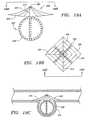
- FIG. 13is a top view of yet another variation of the neck bridge, particularly showing the neck bridge having a braided structure;
- FIGS. 14A and 14Bshow a delivery shape and an unfolded configuration, respectively, of the neck bridge of FIG.
- FIGS. 15A and 15Bshow a variation of the delivery shape and the unfolded configuration, respectively, of the neck bridge of FIG. 13 ;
- FIG. 16is a further variation of the neck bridge, particularly showing the junction region of the neck bridge coupled to a wall section of the inner tubular member;
- FIG. 17is a still further variation of the neck bridge, particularly showing the junction region of the neck bridge coupled to a core wire by a severable joint;
- FIGS. 18A-18Eshow a procedure for introducing an embodiment of the neck bridge, along with a vaso-occlusive device, into an aneurysm;
- FIG. 19Ashows a neck bridge in combination with an "anchor" adapted to be placed within an aneurysm;
- FIG. 19Bis a top view of the neck bridge of FIG. 19A ;
- FIG. 19Cshows a placement of the neck bridge depicted in FIG. 19A within an aneurysm.
- the disclosed inventionrelates to devices and procedures for stabilizing the position and, in some instances, the structure of vaso-occlusive devices placed in a target occlusion site, usually an aneurysm.
- a target occlusion siteusually an aneurysm.
- Use of the retaining devices and neck bridges disclosed hereinreduce the potential migration of vaso-occlusive devices (e.g., helically wound coils) from target occlusion sites, by forming at least a partial barrier at the entrance zone to the aneurysm, i.e., where the aneurysm meets a feeding vessel.
- FIG. 1shows an aneurysm treatment system 100, which includes an aneurysm neck bridge 106.
- the aneurysm treatment system 100also includes a tubular delivery catheter 102, and an inner elongated tubular member 104 slidable within the tubular delivery catheter 102.
- the aneurysm neck bridge 106is removably coupled to a distal end 107 of the elongated tubular member 104 via an electrolytically severable joint 122, and is configured to be placed within an aneurysm sac or directly across a neck (i.e., in between the tissue defining the neck) of an aneurysm.
- the system 100further includes a vaso-occlusive device 108 that is deliverable via the inner tubular member 104.
- the vaso-occlusive device 108is coupled to a core wire 110 via another electrolytically severable joint 130.
- the severable joints 122 and 130are of a scale that cannot easily be seen in FIG. 1 and are depicted in greater clarity in FIG. 2 .
- the electrolytically severable joints 122 and 130are configured to electrically couple to first and second power supplies 112 and 114, respectively, which are used to deliver current to severe the respective joints in a well known manner.
- the severance of the severable joints 122 and 130releases the aneurysm neck bridge 106 and the vaso-occlusive device 108, respectively, at the site.
- a single power supplymay be used to supply current for detachment of the vaso-occlusive device 108 and the aneurysm neck bridge 106.
- FIG. 2is a partial cross section of a distal end of the system 100.
- the distal end 103 of delivery catheter 102carries a radio-opaque marker 116 to assist navigating the distal end 103 through a vasculature.
- the inner tubular member 104also carries a radio-opaque marker 118.
- the inner tubular member 104may have a shape other than that shown in FIG. 2 .
- the inner tubular member 104may have an angle or a curvilinear shape.
- the inner tubular member 104is malleable or heat settable so that a physician or operator can create a desired shape at the time the system 100 is used.
- a conductor wire 120is provided for conducting current from the first power supply 112 to the electrolytically detachable joint 122.
- the aneurysm neck bridge 106includes a junction region 124, which is detachably coupled to a distal end 107 of the inner delivery member 104.
- the junction region 124may include an opening 128 (shown in FIG. 5 ), and may have a shape of a tubular member or a ring.
- the junction region 124preferably fits around the inner tubular member 104 in a loose manner, and is maintained in position only by the electrolytic joint 122.
- the exterior profile of the junction region 124can vary from the circular shape shown in the illustrated embodiment. Examples of variations in the shape of the junction region 124 are shown and described herein.
- the severable joint 122is preferably created by insulating a portion of the conductor wire 120.
- a portion of the conductor wire 120may be insulated with an electrical insulator which is not susceptible to dissolution via electrolysis in blood or other ionic media, leaving the un-insulated portion of the conductor wire 120 susceptible to electrolytic dissolution.
- the electrical insulatormay be the wall of the tubular member 104, as shown in FIG. 2 , or alternatively, it may be a coating placed over the conductor wire 120. Suitable coatings include insulating materials, such as polyfluorocarbons (e.g., Teflon), polyurethane, polyethylene, polypropylene, polyimides, and other suitable polymeric materials.
- the sacrificial joint 122is more susceptible to electrolysis than any other element of the device located near that joint 122.
- current supplied by the first power supply 112passes to the electrolytically severable joint 122, typically with the cooperation of an external return electrode pad (not shown) placed on a skin of a patient to complete the circuit. Passage of current through the electrolytically severable joint 122 causes the joint 122 to severe, thereby de-coupling the neck bridge 106 from the tubular member 104. Further information regarding the construction, placement, and other physical details of electrolytically severable joints used may be found in U.S. Patent Nos.
- the vaso-occlusive device 108may be delivered via the inner tubular member 104.
- the vaso-occlusive device 108is detachably coupled to a distal end of the core wire 110 by the electrolytically severable joint 130, which is formed by insulating a proximal portion of the core wire 110 by an insulating layer 128.
- delivery of vaso-occlusive devices using an electrolytically severable jointis well known in the art.
- the vaso-occlusive device 108may be delivered by using a pusher or plunger, the distal advancement of which within the inner tubular member 104 pushes the vaso-occlusive device 108 out from the distal end of the inner tubular member 104.
- Other methods of delivering the vaso-occlusive device 108 known in the artmay also be used.
- FIG. 3shows another variation of the neck bridge 106.
- the junction region 124 of the neck bridge 106is configured to fit around the distal end 107 of the inner tubular member 104
- the junction region 124 of the neck bridge 106 of FIG. 4is distal to the distal end 107 of the tubular member 104, and is configured to couple to a distal end 107 of the inner tubular member 104 via the severable joint 122.
- the cross sectional dimension of the junction region 124is substantially the same as the cross sectional dimension of the inner delivery member 104 to form a substantially continuous outer surface.
- Vaso-occlusive devices 108 exiting the distal end 107 of the tubular member 104can be delivered to an aneurysm by passing through the opening 128 of the junction region 124, as discussed previously.
- the distal end 107 of the inner tubular member 104may further include a Teflon liner or an extension (not shown) coupled to the interior surface of the inner tubular member 104, such that fluid (e.g., an embolic agent) can be delivered through the opening 128 of the junction region 124 without escaping into the gap between the tip of the inner tubular member 104 and the junction region 124.
- the neck bridge 106includes one or more radially expanding array elements or wires 126 attached to the junction region 124, and a cover 127 attached to the junction region 124.
- the cover 127may also be secured to the array elements 126.
- the cover 127may be attached to both the array elements 126 and the junction region 124.
- the array elements 126 together with the cover 127spread to the general shape shown in FIG. 2 .
- each of the array elements 126is a wire loop or ribbon rim.
- the number of array elements 126may vary between embodiments, depending on factors such as the size of an aneurysm, the width of the tubular delivery catheter 102, and the thickness of the wire making up the array elements 126.
- the array elements 126may be required to undertake relatively significant changes in shape during deployment of the neck bridge 106. To undertake such stress, it is usually preferable that the array elements 126 be produced of a material such as a super-elastic alloy.
- super-elastic or pseudoelastic shape recovery alloysare well known in this art. For instance, U.S. Patent Nos. 3,174,851 , 3,351,463 , and 3,753,700 each describe one of the more well known super-elastic alloys, known as Nitinol. These alloys are characterized by their ability to be transformed from an austenitic crystal structure to a stress-induced martensitic (SIM) structure at certain temperatures and then to return elastically to the austenitic shape when the stress is removed. These alternating crystal structures provide the alloy with its super-elastic properties.
- SIMstress-induced martensitic
- the above described alloysare especially suitable because of their capacity to recover elastically, and almost completely to an unfolded configuration once a bending stress is removed. Typically during use, these alloys suffer little permanent plastic deformation, even at relatively high strains. This ability allows the neck bridge 106 to undertake substantial bends while residing within the lumen 132 of the tubular delivery catheter 102 and while passing through a vasculature. In spite of this bending, the neck bridge 106 returns to its original shape, i.e., unfolded configuration, without retaining any substantial permanent kinks or bends once deployed from the lumen 132.
- the preferred materialis 50.6.+-.2% nickel with most of the remainder being titanium. Up to about 5% of the alloy may be a member of the iron group of metals, particularly chromium and iron.
- the alloyis preferred to not contain more than about 500 parts per million of oxygen, carbon, or nitrogen.
- the transition temperature of this materialis not particularly important, but it should be reasonably below the typical temperature of the human body so as to allow it to be in its austenitic phase during use.
- the wires or ribbons making up the various array elements 126preferably have a diameter less than about 0.254 mm (0.010 inches). These super-elastic alloys are not always sufficiently visible under fluoroscopy as it is used in the human body.
- Radio-opacity coveringsuch as gold and platinum are well known. Radio-opaque metals may be added to the array elements 126 by plating or by wrapping the array element 126 in a radio-opaque wire or ribbon, as is known in the art.
- one or more radio-opaque markersmay be secured to the array elements 126, for example at a perimeter of the neck bridge defined by the array elements 126.
- metalsmay also be appropriate for construction of the array elements 126.
- Such metalsinclude stainless steels and other highly elastic, if not super-elastic, alloys.
- Polymeric materials which are somewhat easier to work with in forming a devicemay also be used for construction of the array elements 126.
- Polymeric materialsare somewhat easier to work with in forming a device.
- Such polymeric materialsmay include members from the group of polyethylene, polypropylene, polytetraflouroethylene, various Nylons, and the like.
- Suitable polymersmay also include most biocompatible materials, which may be made into fibers, including thermoplastics, e.g., polyesters such as polyethyleneterephthalate (PET) especially Dacron; polyamides including Nylons; polyolefins such as polyethylene, polypropylene, polybuylene, their mixtures, alloys, block and random copolymers; polyglycolic acid; polylactic acid; fluoropolymers (polytetrafluoro-ethylene), or even silk or collagen.
- thermoplasticse.g., polyesters such as polyethyleneterephthalate (PET) especially Dacron; polyamides including Nylons; polyolefins such as polyethylene, polypropylene, polybuylene, their mixtures, alloys, block and random copolymers; polyglycolic acid; polylactic acid; fluoropolymers (polytetrafluoro-ethylene), or even silk or collagen.
- PETpolyethyleneterephthalate
- Nylonspolyamides including Nylons
- FIG. 5shows a top view of the neck bridge 106.
- the cover 127is unfolded to have a substantially continuous surface when the array elements 126 assume their unfolded configurations.
- the cover 127may be a fabric, a woven or non-woven mesh, or other sheeting or planar structure.
- the array elements 126are each preferably of a form that retains a large measure of elasticity after having been bent, the cover 127 may be less elastic.
- the cover 127may be made from a variety of materials such as polymers, nylons, and polyester. These materials do not provide substantial strength to the cover 127, so as to allow the device to be readily folded into a low profile and placed into the delivery catheter lumen 132 without adding unnecessary stiffness.
- the sole function of the cover 127is to retain an implanted vaso-occlusive device in an aneurysm.
- the function of the array elements 126is to maintain the structural integrity of the neck bridge device as it is situated within an aneurysm.
- the cover 127may be made to have a similar elasticity as the array elements 126. Therefore, any of the materials discussed previously with reference to the array elements 126 may also be suitable for construction of the cover 127.
- Other materials suitable for construction of the cover 127include Dacron (polyethyleneterephthalate), collageneous materials, polyluorocarbons, combinations thereof, and other vascular graft materials. Fibrous materials, such as polyglycolic acid, wool, or cotton, may also be used.
- FIG. 6shows a variation of the cover 127, which has a braided or mesh-like structure.
- the neck bridge 106includes six array elements 126 attached to the cover 127.
- the cover 127includes a plurality of loops 210, each of which formed by securing ends of a fiber to the junction region 124.
- the loops 210may overlap one another, or alternatively, be inter-woven with each other, to form the cover 127.
- the shape of the loop 210is not limited to that shown in the illustrated embodiment.
- the cover 127may have different braided patterns than those shown herein.
- the cover 127may be placed at a top side of the array elements 126 ( FIG. 7A ), a bottom side of the array elements 126 ( FIG. 7B ), or it may cover both sides of the array elements 126 ( FIG. 7C ).
- the neck bridgemay further include a disk (not shown) placed between the bottom and top surfaces of the cover 127 for reducing the porosity of the neck bridge.
- the shape of the cover 127is not limited to the circular shape shown in the previously discussed embodiments.
- the cover 127can have other shapes, such as an elliptical or rectangular shape ( FIG. 8 ).
- the cover 127is not required to be directly secured to any of the array elements 126. Rather, the array elements 126 exert a bearing and/or frictional force on the cover 127 when they assume an unfolded configuration. However, the cover 127 may optionally be secured to the array elements 126 at one or more various points. The securing may be accomplished using a glue, epoxy, heat bond, or other suitable adhesives, depending upon the materials from which the respective cover 127 and array elements 126 are made. By way of further example, the cover 127 may also be secured to the array elements 126 by sewing them together using a thread.
- Securing the cover 127 to the array elements 126may assist the array elements 126 in unfolding the cover 127 into a desired shape as the array elements 126 assume their unfolded configurations.
- the array elements 126may be embedded within the cover 127, or inter-woven with the cover 127.
- the shape of the individual array elementis not limited to the loop shape shown in the previous variants, and that the array element 126 may have other shapes as well.
- FIG. 8shows a variation of the array element 126 that has a substantially rectilinear profile. As shown in the illustrated variant, the array elements may optionally have blunted tips to avoid trauma to the arteries in which they are placed. The array elements 126 may also have other shapes as well. In the variant of FIG. 8 , the cover 127 has a rectangular shape, as previously noted.
- FIGS. 9A and 9Bshow an embodiment of neck bridge in accordance with the present invention, wherein the array elements 126 are folded in a manner that is different from that shown in FIG. 4 .
- each of the array elements 126has an end 211 coupled to a tip 212.
- the tip 212includes a radio-opaque marker 216.
- the tip 212also includes an opening 217 through which a vaso-occlusive device or occlusion fluid may be delivered.
- the array element 126has a mid portion that flares outward while maintaining the end 211 of the array element 126 in close proximity to an axis 214 of the junction region 124.
- the array elements 126are stretched to the delivery shapes shown in FIG. 9A when positioned within the lumen 132 of the delivery catheter 102, and assume the unfolded configurations shown in FIG. 9B when unconfined outside the delivery catheter 102.
- the array elements 126can also have curvilinear shapes or other unfolded configurations, so long as the array elements 126 unfold the cover 127 once deployed outside the lumen 132 of the delivery catheter 102.
- FIGS. 10A and 10Brespectively show side and top views of another variation of the neck bridge 106, wherein the array elements 126 have upright loop shapes.
- the array elements 126are shown attaching to an interior surface of the junction joint 124, the array elements 126 may also be secured to the ends or the side of the junction joint 124.
- the array elements 126wrap around a perimeter of the cover 127 such that the cover 127 is between the ends of the wires defining the loop shape array elements 126.
- the cover 127may also be placed at a bottom side of the array elements 126.
- FIG.11shows another variation of the neck bridge 220 that is delivered on the exterior of a delivery member 221.
- This variationincludes a number of radially extending array elements 222 which are joined at their outer ends.
- the radially extending array elements 222are joined by a cover 224 which also may be scrim-like.
- the array elements 222are joined to a pair of collars 226 that slide on the delivery member 221 and are controlled by one or more control wires 228.
- Each of the control wires 228may have a releasable joint 229, desirably an electrolytically severable joint, as discussed previously.
- the array elements 222lie generally against the delivery member 221.
- the control wires 228are axially manipulated to extend the radially extending array elements 222 into the deployed shape depicted in FIG. 12 .
- the neck bridgeincludes one or more array elements attached to the cover.
- the array elementsmay not be required.
- FIG. 13shows a variation of the neck bridge which includes a junction region 202 and a braided or mesh-like structure 230 secured to the junction region 202.
- the braided structure 230may carry a radio-opaque marker (not shown), or be plated or coated with a radio-opaque material.
- the braided structure 230is preferably made from an elastic material, such as Nitinol. However, any of the materials discussed previously with reference to the array element 216 may also be suitable for construction of the braided structure 230.
- the advantage of making the braided structure 230 using elastic materialis that the braided structure 230 can assume an unfolded shape without the help of the array elements.
- the braided structure 230may also be made from a radio-opaque material.
- the braided structure 230includes a number of loops 232, each of which formed by securing ends of a fiber to the junction region 202.
- the braided structure 230can have other woven or non-woven patterns as well.
- FIGS. 14A and 14Bshow that the braided structure 230 can assume a delivery shape by bending the loops 232 such that the portions of the loops 232 defining the periphery of the braided structure 230 are distal to both ends of the fibers making up the loops 232.
- FIGS. 15A and 15Bshow a variation of the neck bridge of FIG. 13 .
- a first end of the fiber making up each of the loops 232is secured to a first portion 202a of the junction region 202
- a second end of the fiber making up each of the loops 232is secured to a second portion 202b of the junction region 202.
- the braided structure 230is stretched or bent into a delivery shape such as that shown in FIG. 15A .
- the first portion 202a and the second portion 202b of the junction regionmove closer to each other, and the portion of the loop 232 near the mid-section 234 of the loop 232 becomes the periphery of the braided structure 230.
- the manner in which the braided structure 230 is folded or deployedshould not be limited to the examples described previously, and that other methods of folding or deploying the braided structure 230 can also be used.
- the junction regionincludes the opening 128 through which a vaso-occlusive device 108 may be delivered.
- the opening 128is optional.
- FIG. 16shows a cross sectional view of a variation of the junction region 124 that does not have the opening 128.
- the junction region 124is detachably secured to a wall section of the inner tubular member 104 by an electrolytically severable joint 240.
- the vaso-occlusive device 108may also be delivered via the inner tubular member 104, as discussed previously.
- FIG. 17shows a cross sectional view of a neck bridge 126 that is detachably coupled to a core wire 250 by an electrolytically severable joint 252.
- a proximal portion of the core wire 250is insulated by an insulating layer 254 to form the severable joint 252.
- the delivery catheter 102is used to deliver both the neck bridge 106 and the vaso-occlusive device 108.
- the delivery catheter 102is inserted into the body of a patient. Typically, this would be through a femoral artery in the groin. Other entry sites sometimes chosen are found in the neck and are in general well known by physicians who practice these types of medical procedures.
- the delivery catheter 102which may be a microcatheter or a sheath, may be positioned so that the distal end of the delivery catheter 102 is appropriately situated, e.g., near the neck of an aneurysm 306 to be treated. ( FIG. 18A )
- the placement of the delivery catheter 102may be assisted by the use of guide wire and/or a radio-opaque marker, as are known in the art.
- a neck bridge 308which is representative of any of the neck bridges discussed previously, is carried within the delivery catheter 102 before it is deployed. While positioned within the delivery catheter 102, the neck bridge 308 is stretched into a delivery shape. If the neck bridge 308 is coupled to the inner tubular member 104, the neck bridge 308 may be deployed by retracting the delivery catheter 102 relative to the tubular member 104, or by advancing the tubular member 104 relative to the delivery catheter 102. Alternatively, if the neck bridge 308 is coupled to the core wire 250, such as that shown in FIG. 17 , the neck bridge 308 may be deployed by retracting the delivery catheter 102 relative to the core wire 250 or by advancing the core wire 250 relative to the delivery catheter 102. Once the neck bridge 308 is unconfined outside the delivery catheter 102, it assumes an unfolded configuration. FIG. 18B shows the neck bridge 308 having been deployed and placed within the aneurysm 306.
- one or more vaso-occlusive devices 314may be delivered into the aneurysm using any of the conventional methods.
- FIG. 18CIf the neck bridge 308 includes a junction region 316 that has an opening, such as the opening 128 shown in FIG. 5 , the vaso-occlusive device 314 may be delivered via the inner tubular member 104, through the opening 128 of the junction region 316 of the neck bridge 308, and into the aneurysm 306.
- occlusion substancesuch as occlusion fluid or occlusion particles may also be delivered through the opening of the junction region 316 and into the aneurysm 306.
- the vaso-occlusive device 314may be delivered to the aneurysm 306 along a path that is exterior to the tubular member 104 or to the core wire 250 if one is used. In this case, the neck bridge 308 should be made sufficiently flexible to distend around the vaso-occlusive delivery device.
- the vaso-occlusive device 314may be delivered into the aneurysm 306 by going through an opening in the cover, such as a pre-made opening, or an opening defined by the fibers making up the cover. The vaso-occlusive device 314 may also be delivered into the aneurysm by puncturing the cover of the neck bridge 308.
- the electrolytically severable joint 122(or joint 129, 140, or 252) is then severed, thereby de-coupling the neck bridge 308 from the tubular member 104 or from the core wire 250 if one is used.
- FIGS. 18D and 18EThe delivery catheter 102 and the inner tubular member 104 are then withdrawn, leaving the vaso-occlusive device 314 in place within the aneurysm 306. As shown in FIG.
- the neck bridge 308stabilizes the presence of the vaso-occlusive device 314 and prevents the vaso-occlusive coil 314 from being drawn or escaping into the feed vessel.
- a stent or a perfusion balloonmay optionally be placed in the parent vessel to help seat the neck bridge 308 within the aneurysm 306.
- FIGS. 19A-19Cshow another variation of the neck bridge 400 having a junction region 402, a number of radially extending array elements 404, and a cover 406.
- the neck bridge 400also includes a cage 408 made up of a plurality of, e.g., platinum or nickel-titanium coils or wires 409.
- a connector 410connects the cage 408 to the junction region 402 or to the array elements 404, and is situated within the neck of the aneurysm after implantation.
- the array elements 404are typically joined to a releasable joint, which may be an electrolytically severable joint as discussed previously.
- the cage 408extends outwardly from the general center-line of the device and generally should be sized to conform to the size of, and generally to the shape of, the aneurysm.
- FIG. 19Cshows the general placement of the device within an aneurysm 414.
- the method of using the neck bridge 400is similar to that described previously with reference to FIGS. 18A-18E .
Landscapes
- Health & Medical Sciences (AREA)
- Surgery (AREA)
- Life Sciences & Earth Sciences (AREA)
- Heart & Thoracic Surgery (AREA)
- Molecular Biology (AREA)
- Vascular Medicine (AREA)
- Engineering & Computer Science (AREA)
- Biomedical Technology (AREA)
- Reproductive Health (AREA)
- Medical Informatics (AREA)
- Nuclear Medicine, Radiotherapy & Molecular Imaging (AREA)
- Animal Behavior & Ethology (AREA)
- General Health & Medical Sciences (AREA)
- Public Health (AREA)
- Veterinary Medicine (AREA)
- Neurosurgery (AREA)
- Surgical Instruments (AREA)
- Prostheses (AREA)
- Apparatus For Radiation Diagnosis (AREA)
Abstract
Description
- The invention pertains to systems and apparatus for treating aneurysms, and more specifically, to systems and apparatus for bridging a neck of an aneurysm.
- Various implantable medical devices have been developed for treating a number of ailments associated with body lumens. In particular, occlusive devices have been proven useful in filling vascular aneurysms, which are formed due to a weakening in the wall of an artery. Vascular aneurysms are often the site of internal bleeding and stroke. A variety of different embolic agents are known to be, at least arguably, suitable for treatment of vascular aneurysms by filling them to prevent further vessel wall weakening or rupture. Use of these agents are commonly known as "artificial vaso-occlusion."
- Over the past few years, advancements in the artificial occlusion of vessels and aneurysms have included the delivery and implantation of metal coils as vaso-occlusive devices. Implantable metal coils that are useful as artificial occlusion devices in vasculature lumens or aneurysms are herein referred to as "vaso-occlusive coils." Vaso-occlusive coils are typically constructed of a wire made of a metal or metal alloy wound into a helix. Such vaso-occlusive coils are typically manufactured to assume a certain shape upon discharge of the device from the distal end of the catheter into a treatment site. A variety of such vaso-occlusive coils are known. For instance,
U.S. Patent No. 4,994,069 , ("the '069 patent"), discloses a flexible, preferably coiled wire for use in small vessel vaso-occlusion. Unlike vaso-occlusive coils used prior to that time, the '069 patent discloses using a coil that is relatively soft and is delivered to the site using a pusher within a catheter lumen. Upon discharge from the delivery catheter, the coil may undertake a number of random or predetermined configurations useful to fill the site. - Known vaso-occlusive coils may be used for filling relatively small vessel sites, e.g., 0.5-6.0 mm in diameter. The coils themselves are described as being between 0.254 and 0.762 mm in diameter. The length of the wire making up the vaso-occlusive coil is typically 15 to 20 times the diameter of the vessel to be occluded. The wire used to make up the coils may be, for instance, 0.051 to 0.152 mm in diameter. Tungsten, platinum, and gold threads or wires are typically preferred. These coils have a variety of benefits, including the fact that they are relatively permanent, they may be easily imaged radiographically, they may be located at a well defined vessel site, and they can be retrieved, if necessary.
- In addition to the various types of known space filling mechanisms and geometries of vaso-occlusive coils, other particularized features of coil designs, such as mechanisms for their delivery through catheters and implanting them in a desired occlusion site, are well know in the art. Examples of known vaso-occlusive coils categorized by their delivery mechanisms include pushable coils, mechanically detachable coils, and electrolytically detachably coils. One example of a "pushable coil" is disclosed in Ritchart et al., discussed above. Pushable coils are commonly provided in a cartridge and are pushed or "plunged" from the cartridge into a lumen of a delivery catheter. A pusher (e.g., a wire or a pressurized fluid) advances the pushable coil through and out of the delivery catheter lumen, into the desired occlusion site.
- Mechanically detachable vaso-occlusive coils are typically integrated with a pusher rod and are mechanically detached from the distal end of that pusher after exiting a delivery catheter. Examples of such mechanically detachable vaso-occlusive coils are found in
U.S. Patent Nos. 5,261,916 and5,250,071 . Examples of electrolytically detachable vaso-occlusive coils may be found inU.S. Patent Nos. 5,122,136 and5,354,295 . In these devices, the vaso-occlusive portion of the assembly is attached to a pusher via a small, electrolytically severable joint. The electrolytically severable joint is eroded by the placement of an appropriate voltage on the core wire. - As noted above, aneurysms present a particularly acute medical risk due to the dangers of potential rupture of the thin vascular wall inherent in such aneurysms. Occlusion of aneurysms by use of vaso-occlusive coils without occluding the adjacent artery is a special challenge and is a desirable method of reducing such risk of rupture. Vaso-occlusive devices may be placed in an aneurysm in a manner described in
U.S. Patent No. 4,739,768 . In particular, a microcatheter is initially steered into or adjacent to the entrance of an aneurysm, typically aided by the use of a steerable guidewire. The wire is then withdrawn from the microcatheter lumen and replaced by one or more vaso-occlusive coils, which are then advanced through and out of the microcatheter, and into the aneurysm. - However, after, or perhaps during delivery of a coil into the aneurysm, there is a risk that a portion of the coil might migrate out of the aneurysm entrance zone and into the feeding vessel. The presence of the coil in that feeding vessel may cause a highly undesirable occlusion there. Also, there is a risk that the blood flow in the vessel and aneurysm may induce movement of the coil farther out of the aneurysm, resulting in a more developed embolus in the feeding vessel.
- One type of aneurysm, commonly known as a "wide neck" aneurysm, is known to present particular difficulty in the placement and retention of vaso-occlusive coils, because vaso-occlusive coils lacking substantial secondary shape strength may be difficult to maintain in position within an aneurysm no matter how skillfully they are placed. Wide neck aneurysms are herein referred to as aneurysms of vessel walls having a neck or "entrance zone" from the adjacent vessel, wherein the entrance zone has a diameter that either: (1) is at least 80% of the largest diameter of the aneurysm; or (2) is clinically observed to be too wide effectively to retain commercially available vaso-occlusive coils that are deployed using the techniques discussed above.
- Certain techniques have been developed in order to deal with the disadvantages associated with embolic material migration into the parent vessel. One such technique, commonly referred to as flow arrest, involves temporarily occluding the parent vessel proximal of the aneurysm, so that no blood flow occurs through the parent vessel until a thrombotic mass has formed in the sac of the aneurysm. While this technique helps reduce the tendency of the embolic material to migrate out of the aneurysm sac, a thrombotic mass can still dissolve through normal lysis of blood. Also, occluding the parent vessel may not prevent all embolic material migration into the parent vessel. Further, in certain cases, it is highly undesirable to occlude the parent vessel even temporarily. Thus, a flow arrest technique is, at times, not effective or even not available as a treatment option.
- Another approach to occlude a wide neck aneurysm is described in
U.S. Patent No. 6,168,622 ("the '622 patent"), which describes a vaso-occlusive device with a secondary shape having a bulbous body portion and an anchor. The bulbous body portion is deployed within the aneurysm while the anchor is set just outside of the aneurysm, covering the aneurysm's neck or entrance zone. As described in the '622 patent, the device may be integrally formed from a tube - clamped at both ends - of braided Nickel-Titanium (NiTi) wires. The bulbous body functions to occlude the aneurysm, while the anchor covers the entrance zone. In some cases, it may still be desirable to deploy vaso-occlusive coils with such a device, but the bulbous body of the vaso-occlusive device may not provide much space within the aneurysm to allow for insertion and deployment of coils. WO-A-00/13593 - According to the present invention there is provided a device for bridging a neck of an aneurysm as defined in claim 1.
- An embodiment of device in accordance with the present invention will now be described, by way of example only, with reference to the accompanying drawings. Of the described and illustrated devices, only the
Fig 9A/9B device is in accordance with the present invention. Nevertheless, the other drawings and description assist in understanding the invention, and similar elements in the different drawings are referred to by common reference numerals.FIG. 1 is a cross sectional plan view of an aneurysm treatment system including a neck bridge comprising an array of elements;FIG. 2 is a partial cross sectional view of a distal end of the system ofFIG. 1 ;FIG. 3 is a partial cross sectional view of a variation of the distal end of the system ofFIG. 1 , particularly showing a junction region of the neck bridge coupling to a distal tip of an inner tubular member;FIG. 4 is a partial cross sectional view of the distal end of the inner tubular member shown inFIG. 3 , particularly showing the neck bridge assuming a delivery shape;FIG. 5 is a top view of the neck bridge ofFIG. 1 ;FIG. 6 is a top view of a variation of the neck bridge, particularly showing a cover having a plurality of loops;FIGS. 7A-7C are side views of further variations of the neck bridge;FIG. 8 is a top view of a still further variation of the neck bridge, particularly showing the array elements having substantially rectilinear shapes;FIGS. 9A and9B show an embodiment of neck bridge in accordance with the present invention, particularly showing the array elements having different unfolded configurations;FIGS. 10A and10B show yet another variation of the neck bridge, particularly showing the array elements having upright loop shapes;FIG.11 is a side view of a still another variation of the neck bridge, particularly showing the neck bridge having a pair of collars coupled to control wires;FIG. 12 is a top view of the neck bridge ofFIG. 11 in a deployed (i.e., non-constrained) configuration;FIG. 13 is a top view of yet another variation of the neck bridge, particularly showing the neck bridge having a braided structure;FIGS. 14A and14B show a delivery shape and an unfolded configuration, respectively, of the neck bridge ofFIG. 13 ;FIGS. 15A and 15B show a variation of the delivery shape and the unfolded configuration, respectively, of the neck bridge ofFIG. 13 ;FIG. 16 is a further variation of the neck bridge, particularly showing the junction region of the neck bridge coupled to a wall section of the inner tubular member;FIG. 17 is a still further variation of the neck bridge, particularly showing the junction region of the neck bridge coupled to a core wire by a severable joint;FIGS. 18A-18E show a procedure for introducing an embodiment of the neck bridge, along with a vaso-occlusive device, into an aneurysm;FIG. 19A shows a neck bridge in combination with an "anchor" adapted to be placed within an aneurysm;FIG. 19B is a top view of the neck bridge ofFIG. 19A ; andFIG. 19C shows a placement of the neck bridge depicted inFIG. 19A within an aneurysm. - The disclosed invention relates to devices and procedures for stabilizing the position and, in some instances, the structure of vaso-occlusive devices placed in a target occlusion site, usually an aneurysm. Use of the retaining devices and neck bridges disclosed herein reduce the potential migration of vaso-occlusive devices (e.g., helically wound coils) from target occlusion sites, by forming at least a partial barrier at the entrance zone to the aneurysm, i.e., where the aneurysm meets a feeding vessel.
FIG. 1 shows ananeurysm treatment system 100, which includes ananeurysm neck bridge 106. Theaneurysm treatment system 100 also includes atubular delivery catheter 102, and an inner elongatedtubular member 104 slidable within thetubular delivery catheter 102. Theaneurysm neck bridge 106 is removably coupled to adistal end 107 of theelongated tubular member 104 via an electrolytically severable joint 122, and is configured to be placed within an aneurysm sac or directly across a neck (i.e., in between the tissue defining the neck) of an aneurysm. Thesystem 100 further includes a vaso-occlusive device 108 that is deliverable via the innertubular member 104. The vaso-occlusive device 108 is coupled to acore wire 110 via another electrolytically severable joint 130. Theseverable joints FIG. 1 and are depicted in greater clarity inFIG. 2 .- Schematically, the electrolytically
severable joints second power supplies severable joints aneurysm neck bridge 106 and the vaso-occlusive device 108, respectively, at the site. Alternatively, a single power supply may be used to supply current for detachment of the vaso-occlusive device 108 and theaneurysm neck bridge 106. FIG. 2 is a partial cross section of a distal end of thesystem 100. Thedistal end 103 ofdelivery catheter 102 carries a radio-opaque marker 116 to assist navigating thedistal end 103 through a vasculature. The innertubular member 104 also carries a radio-opaque marker 118. In alternate embodiments, the innertubular member 104 may have a shape other than that shown inFIG. 2 . For example, the innertubular member 104 may have an angle or a curvilinear shape. Preferably, the innertubular member 104 is malleable or heat settable so that a physician or operator can create a desired shape at the time thesystem 100 is used.- A
conductor wire 120 is provided for conducting current from thefirst power supply 112 to the electrolytically detachable joint 122. Theaneurysm neck bridge 106 includes ajunction region 124, which is detachably coupled to adistal end 107 of theinner delivery member 104. Thejunction region 124 may include an opening 128 (shown inFIG. 5 ), and may have a shape of a tubular member or a ring. Thejunction region 124 preferably fits around the innertubular member 104 in a loose manner, and is maintained in position only by theelectrolytic joint 122. In alternate embodiments, the exterior profile of thejunction region 124 can vary from the circular shape shown in the illustrated embodiment. Examples of variations in the shape of thejunction region 124 are shown and described herein. - The severable joint 122 is preferably created by insulating a portion of the
conductor wire 120. For example, a portion of theconductor wire 120 may be insulated with an electrical insulator which is not susceptible to dissolution via electrolysis in blood or other ionic media, leaving the un-insulated portion of theconductor wire 120 susceptible to electrolytic dissolution. The electrical insulator may be the wall of thetubular member 104, as shown inFIG. 2 , or alternatively, it may be a coating placed over theconductor wire 120. Suitable coatings include insulating materials, such as polyfluorocarbons (e.g., Teflon), polyurethane, polyethylene, polypropylene, polyimides, and other suitable polymeric materials. It will also be apparent that the sacrificial joint 122 is more susceptible to electrolysis than any other element of the device located near that joint 122. In use, current supplied by thefirst power supply 112 passes to the electrolytically severable joint 122, typically with the cooperation of an external return electrode pad (not shown) placed on a skin of a patient to complete the circuit. Passage of current through the electrolytically severable joint 122 causes the joint 122 to severe, thereby de-coupling theneck bridge 106 from thetubular member 104. Further information regarding the construction, placement, and other physical details of electrolytically severable joints used may be found inU.S. Patent Nos. 5,234,437 ,5,250,071 ,5,261,916 ,5,304,195 ,5,312,415 , and5,350,397 . It will be appreciated that mechanical joints, and other types of detachable joints known in the art for placing occlusive devices in aneurysms may alternatively be used to couple theneck bridge 106 to thetubular member 104. Examples of such mechanical joints may be found inU.S. Patent Nos. 5,234,437 ,5,250,071 ,5,261,916 ,5,304,195 ,5,312,415 , and5,350,397 . - As shown in
FIG. 2 , because theneck bridge 106 is coupled to thetubular member 104 in a way that does not obstruct thedistal opening 131 of thetubular member 104, the vaso-occlusive device 108 may be delivered via the innertubular member 104. In the illustrated embodiment, the vaso-occlusive device 108 is detachably coupled to a distal end of thecore wire 110 by the electrolytically severable joint 130, which is formed by insulating a proximal portion of thecore wire 110 by an insulatinglayer 128. As noted above, delivery of vaso-occlusive devices using an electrolytically severable joint is well known in the art. Alternatively, the vaso-occlusive device 108 may be delivered by using a pusher or plunger, the distal advancement of which within the innertubular member 104 pushes the vaso-occlusive device 108 out from the distal end of the innertubular member 104. Other methods of delivering the vaso-occlusive device 108 known in the art may also be used. FIG. 3 shows another variation of theneck bridge 106. Unlike the previously shown embodiment, in which thejunction region 124 of theneck bridge 106 is configured to fit around thedistal end 107 of the innertubular member 104, thejunction region 124 of theneck bridge 106 ofFIG. 4 is distal to thedistal end 107 of thetubular member 104, and is configured to couple to adistal end 107 of the innertubular member 104 via theseverable joint 122. In this variation, the cross sectional dimension of thejunction region 124 is substantially the same as the cross sectional dimension of theinner delivery member 104 to form a substantially continuous outer surface. Vaso-occlusive devices 108 exiting thedistal end 107 of thetubular member 104 can be delivered to an aneurysm by passing through theopening 128 of thejunction region 124, as discussed previously. Thedistal end 107 of the innertubular member 104 may further include a Teflon liner or an extension (not shown) coupled to the interior surface of the innertubular member 104, such that fluid (e.g., an embolic agent) can be delivered through theopening 128 of thejunction region 124 without escaping into the gap between the tip of the innertubular member 104 and thejunction region 124.- The
neck bridge 106 includes one or more radially expanding array elements orwires 126 attached to thejunction region 124, and acover 127 attached to thejunction region 124. In alternate embodiments, thecover 127 may also be secured to thearray elements 126. In further alternate embodiments, thecover 127 may be attached to both thearray elements 126 and thejunction region 124. Upon placement in an aneurysm, thearray elements 126 together with thecover 127 spread to the general shape shown inFIG. 2 . In the illustrated embodiment, each of thearray elements 126 is a wire loop or ribbon rim. The number ofarray elements 126 may vary between embodiments, depending on factors such as the size of an aneurysm, the width of thetubular delivery catheter 102, and the thickness of the wire making up thearray elements 126. Before theneck bridge 106 is deployed to a target site, theneck bridge 106 resides within alumen 132 of thedelivery catheter 102, and it is generally stretched to assume and maintain the shape of thelumen 132 as shown inFIG. 4 . Thecover 127 is folded into a low profile when positioned in thelumen 132. When theneck bridge 106 is pushed from the distal end of thedelivery catheter 102, thearray elements 126 assume their so-called "unfolded" shapes or configurations, thereby unfolding thecover 127. - The
array elements 126 may be required to undertake relatively significant changes in shape during deployment of theneck bridge 106. To undertake such stress, it is usually preferable that thearray elements 126 be produced of a material such as a super-elastic alloy. Super-elastic or pseudoelastic shape recovery alloys are well known in this art. For instance,U.S. Patent Nos. 3,174,851 ,3,351,463 , and3,753,700 each describe one of the more well known super-elastic alloys, known as Nitinol. These alloys are characterized by their ability to be transformed from an austenitic crystal structure to a stress-induced martensitic (SIM) structure at certain temperatures and then to return elastically to the austenitic shape when the stress is removed. These alternating crystal structures provide the alloy with its super-elastic properties. - The above described alloys are especially suitable because of their capacity to recover elastically, and almost completely to an unfolded configuration once a bending stress is removed. Typically during use, these alloys suffer little permanent plastic deformation, even at relatively high strains. This ability allows the
neck bridge 106 to undertake substantial bends while residing within thelumen 132 of thetubular delivery catheter 102 and while passing through a vasculature. In spite of this bending, theneck bridge 106 returns to its original shape, i.e., unfolded configuration, without retaining any substantial permanent kinks or bends once deployed from thelumen 132. - Of the super-elastic alloys currently available, the preferred material is 50.6.+-.2% nickel with most of the remainder being titanium. Up to about 5% of the alloy may be a member of the iron group of metals, particularly chromium and iron. The alloy is preferred to not contain more than about 500 parts per million of oxygen, carbon, or nitrogen. The transition temperature of this material is not particularly important, but it should be reasonably below the typical temperature of the human body so as to allow it to be in its austenitic phase during use. The wires or ribbons making up the
various array elements 126 preferably have a diameter less than about 0.254 mm (0.010 inches). These super-elastic alloys are not always sufficiently visible under fluoroscopy as it is used in the human body. Consequently it may be desirable to add a radio-opacity covering to thearray elements 126. Radio-opaque metals such as gold and platinum are well known. Radio-opaque metals may be added to thearray elements 126 by plating or by wrapping thearray element 126 in a radio-opaque wire or ribbon, as is known in the art. - Alternatively, one or more radio-opaque markers may be secured to the
array elements 126, for example at a perimeter of the neck bridge defined by thearray elements 126. - Other metals may also be appropriate for construction of the
array elements 126. Such metals include stainless steels and other highly elastic, if not super-elastic, alloys. Polymeric materials which are somewhat easier to work with in forming a device may also be used for construction of thearray elements 126. Polymeric materials are somewhat easier to work with in forming a device. Such polymeric materials may include members from the group of polyethylene, polypropylene, polytetraflouroethylene, various Nylons, and the like. Suitable polymers may also include most biocompatible materials, which may be made into fibers, including thermoplastics, e.g., polyesters such as polyethyleneterephthalate (PET) especially Dacron; polyamides including Nylons; polyolefins such as polyethylene, polypropylene, polybuylene, their mixtures, alloys, block and random copolymers; polyglycolic acid; polylactic acid; fluoropolymers (polytetrafluoro-ethylene), or even silk or collagen. FIG. 5 shows a top view of theneck bridge 106. As shown inFIG. 5 , thecover 127 is unfolded to have a substantially continuous surface when thearray elements 126 assume their unfolded configurations. Thecover 127 may be a fabric, a woven or non-woven mesh, or other sheeting or planar structure. Although thearray elements 126 are each preferably of a form that retains a large measure of elasticity after having been bent, thecover 127 may be less elastic. Thecover 127 may be made from a variety of materials such as polymers, nylons, and polyester. These materials do not provide substantial strength to thecover 127, so as to allow the device to be readily folded into a low profile and placed into thedelivery catheter lumen 132 without adding unnecessary stiffness. The sole function of thecover 127 is to retain an implanted vaso-occlusive device in an aneurysm. The function of thearray elements 126 is to maintain the structural integrity of the neck bridge device as it is situated within an aneurysm. Alternatively, thecover 127 may be made to have a similar elasticity as thearray elements 126. Therefore, any of the materials discussed previously with reference to thearray elements 126 may also be suitable for construction of thecover 127. Other materials suitable for construction of thecover 127 include Dacron (polyethyleneterephthalate), collageneous materials, polyluorocarbons, combinations thereof, and other vascular graft materials. Fibrous materials, such as polyglycolic acid, wool, or cotton, may also be used.FIG. 6 shows a variation of thecover 127, which has a braided or mesh-like structure. In the illustrated embodiment, theneck bridge 106 includes sixarray elements 126 attached to thecover 127. Thecover 127 includes a plurality ofloops 210, each of which formed by securing ends of a fiber to thejunction region 124. Theloops 210 may overlap one another, or alternatively, be inter-woven with each other, to form thecover 127. It should be noted that the shape of theloop 210 is not limited to that shown in the illustrated embodiment. Furthermore, thecover 127 may have different braided patterns than those shown herein.- In each of the above-described neck bridges, the
cover 127 may be placed at a top side of the array elements 126 (FIG. 7A ), a bottom side of the array elements 126 (FIG. 7B ), or it may cover both sides of the array elements 126 (FIG. 7C ). In the variant of neck bridge shown inFIG. 7C , the neck bridge may further include a disk (not shown) placed between the bottom and top surfaces of thecover 127 for reducing the porosity of the neck bridge. Notably, the shape of thecover 127 is not limited to the circular shape shown in the previously discussed embodiments. Thecover 127 can have other shapes, such as an elliptical or rectangular shape (FIG. 8 ). - Generally, as with the variants shown in
FIGS. 7A and7C , thecover 127 is not required to be directly secured to any of thearray elements 126. Rather, thearray elements 126 exert a bearing and/or frictional force on thecover 127 when they assume an unfolded configuration. However, thecover 127 may optionally be secured to thearray elements 126 at one or more various points. The securing may be accomplished using a glue, epoxy, heat bond, or other suitable adhesives, depending upon the materials from which therespective cover 127 andarray elements 126 are made. By way of further example, thecover 127 may also be secured to thearray elements 126 by sewing them together using a thread. Securing thecover 127 to thearray elements 126 may assist thearray elements 126 in unfolding thecover 127 into a desired shape as thearray elements 126 assume their unfolded configurations. Alternatively, thearray elements 126 may be embedded within thecover 127, or inter-woven with thecover 127. - It should be noted that the shape of the individual array element is not limited to the loop shape shown in the previous variants, and that the
array element 126 may have other shapes as well.FIG. 8 shows a variation of thearray element 126 that has a substantially rectilinear profile. As shown in the illustrated variant, the array elements may optionally have blunted tips to avoid trauma to the arteries in which they are placed. Thearray elements 126 may also have other shapes as well. In the variant ofFIG. 8 , thecover 127 has a rectangular shape, as previously noted. - The manner in which the array elements fold or bend when positioned within the lumen of a tubular delivery member is not limited. By way of illustration,
FIGS. 9A and9B show an embodiment of neck bridge in accordance with the present invention, wherein thearray elements 126 are folded in a manner that is different from that shown inFIG. 4 . In the embodiment ofFIGS.9A and9B , each of thearray elements 126 has anend 211 coupled to atip 212. Thetip 212 includes a radio-opaque marker 216. Thetip 212 also includes anopening 217 through which a vaso-occlusive device or occlusion fluid may be delivered. Thearray element 126 has a mid portion that flares outward while maintaining theend 211 of thearray element 126 in close proximity to anaxis 214 of thejunction region 124. Thearray elements 126 are stretched to the delivery shapes shown inFIG. 9A when positioned within thelumen 132 of thedelivery catheter 102, and assume the unfolded configurations shown inFIG. 9B when unconfined outside thedelivery catheter 102. Thearray elements 126 can also have curvilinear shapes or other unfolded configurations, so long as thearray elements 126 unfold thecover 127 once deployed outside thelumen 132 of thedelivery catheter 102. FIGS. 10A and10B , respectively show side and top views of another variation of theneck bridge 106, wherein thearray elements 126 have upright loop shapes. Although thearray elements 126 are shown attaching to an interior surface of thejunction joint 124, thearray elements 126 may also be secured to the ends or the side of thejunction joint 124. In the illustrated embodiment, thearray elements 126 wrap around a perimeter of thecover 127 such that thecover 127 is between the ends of the wires defining the loopshape array elements 126. Alternatively, as shown by the dashed-lines, thecover 127 may also be placed at a bottom side of thearray elements 126.- The
array elements 126 may also be deployed using mechanical methods.FIG.11 shows another variation of the neck bridge 220 that is delivered on the exterior of adelivery member 221. This variation includes a number of radially extendingarray elements 222 which are joined at their outer ends. The radially extendingarray elements 222 are joined by acover 224 which also may be scrim-like. Thearray elements 222 are joined to a pair ofcollars 226 that slide on thedelivery member 221 and are controlled by one ormore control wires 228. Each of thecontrol wires 228 may have a releasable joint 229, desirably an electrolytically severable joint, as discussed previously. During delivery of the neck bridge 220, thearray elements 222 lie generally against thedelivery member 221. During deployment, thecontrol wires 228 are axially manipulated to extend the radially extendingarray elements 222 into the deployed shape depicted inFIG. 12 . - In the previously discussed variants, the neck bridge includes one or more array elements attached to the cover. However, the array elements may not be required.
FIG. 13 shows a variation of the neck bridge which includes ajunction region 202 and a braided or mesh-like structure 230 secured to thejunction region 202. Thebraided structure 230 may carry a radio-opaque marker (not shown), or be plated or coated with a radio-opaque material. Thebraided structure 230 is preferably made from an elastic material, such as Nitinol. However, any of the materials discussed previously with reference to thearray element 216 may also be suitable for construction of thebraided structure 230. The advantage of making thebraided structure 230 using elastic material is that thebraided structure 230 can assume an unfolded shape without the help of the array elements. Thebraided structure 230 may also be made from a radio-opaque material. In the illustrated embodiment, thebraided structure 230 includes a number ofloops 232, each of which formed by securing ends of a fiber to thejunction region 202. However, thebraided structure 230 can have other woven or non-woven patterns as well. FIGS. 14A and14B show that thebraided structure 230 can assume a delivery shape by bending theloops 232 such that the portions of theloops 232 defining the periphery of thebraided structure 230 are distal to both ends of the fibers making up theloops 232.FIGS. 15A and15B show a variation of the neck bridge ofFIG. 13 . As shown in the embodiment, a first end of the fiber making up each of theloops 232 is secured to afirst portion 202a of thejunction region 202, and a second end of the fiber making up each of theloops 232 is secured to asecond portion 202b of thejunction region 202. When residing within thedelivery catheter 102, thebraided structure 230 is stretched or bent into a delivery shape such as that shown inFIG. 15A . When the neck bridge is deployed outside thedelivery catheter 102, thefirst portion 202a and thesecond portion 202b of the junction region move closer to each other, and the portion of theloop 232 near themid-section 234 of theloop 232 becomes the periphery of thebraided structure 230. It should be noted that the manner in which thebraided structure 230 is folded or deployed should not be limited to the examples described previously, and that other methods of folding or deploying thebraided structure 230 can also be used.- In all of the previously described variants, the junction region includes the
opening 128 through which a vaso-occlusive device 108 may be delivered. However, theopening 128 is optional.FIG. 16 shows a cross sectional view of a variation of thejunction region 124 that does not have theopening 128. In the illustrated variant, thejunction region 124 is detachably secured to a wall section of the innertubular member 104 by an electrolytically severable joint 240. The vaso-occlusive device 108 may also be delivered via the innertubular member 104, as discussed previously. - The
neck bridge 126 may be detachably coupled to other structures instead of the innertubular member 104 described previously.FIG. 17 shows a cross sectional view of aneck bridge 126 that is detachably coupled to acore wire 250 by an electrolytically severable joint 252. A proximal portion of thecore wire 250 is insulated by an insulatinglayer 254 to form theseverable joint 252. In this case, thedelivery catheter 102 is used to deliver both theneck bridge 106 and the vaso-occlusive device 108. - The method of using the previously described neck bridges will now be discussed with reference to
FIGS. 18A-18E . First, thedelivery catheter 102 is inserted into the body of a patient. Typically, this would be through a femoral artery in the groin. Other entry sites sometimes chosen are found in the neck and are in general well known by physicians who practice these types of medical procedures. Thedelivery catheter 102, which may be a microcatheter or a sheath, may be positioned so that the distal end of thedelivery catheter 102 is appropriately situated, e.g., near the neck of ananeurysm 306 to be treated. (FIG. 18A ) The placement of thedelivery catheter 102 may be assisted by the use of guide wire and/or a radio-opaque marker, as are known in the art. - A
neck bridge 308, which is representative of any of the neck bridges discussed previously, is carried within thedelivery catheter 102 before it is deployed. While positioned within thedelivery catheter 102, theneck bridge 308 is stretched into a delivery shape. If theneck bridge 308 is coupled to the innertubular member 104, theneck bridge 308 may be deployed by retracting thedelivery catheter 102 relative to thetubular member 104, or by advancing thetubular member 104 relative to thedelivery catheter 102. Alternatively, if theneck bridge 308 is coupled to thecore wire 250, such as that shown inFIG. 17 , theneck bridge 308 may be deployed by retracting thedelivery catheter 102 relative to thecore wire 250 or by advancing thecore wire 250 relative to thedelivery catheter 102. Once theneck bridge 308 is unconfined outside thedelivery catheter 102, it assumes an unfolded configuration.FIG. 18B shows theneck bridge 308 having been deployed and placed within theaneurysm 306. - Next, one or more vaso-
occlusive devices 314 may be delivered into the aneurysm using any of the conventional methods. (FIG. 18C ) If theneck bridge 308 includes ajunction region 316 that has an opening, such as theopening 128 shown inFIG. 5 , the vaso-occlusive device 314 may be delivered via the innertubular member 104, through theopening 128 of thejunction region 316 of theneck bridge 308, and into theaneurysm 306. It should be noted that instead of vaso-occlusive devices, other occlusion substance such as occlusion fluid or occlusion particles may also be delivered through the opening of thejunction region 316 and into theaneurysm 306. If thejunction region 316 of theneck bridge 308 does not have an opening, such as the variant shown inFIG. 16 or17 , the vaso-occlusive device 314 may be delivered to theaneurysm 306 along a path that is exterior to thetubular member 104 or to thecore wire 250 if one is used. In this case, theneck bridge 308 should be made sufficiently flexible to distend around the vaso-occlusive delivery device. Alternatively, the vaso-occlusive device 314 may be delivered into theaneurysm 306 by going through an opening in the cover, such as a pre-made opening, or an opening defined by the fibers making up the cover. The vaso-occlusive device 314 may also be delivered into the aneurysm by puncturing the cover of theneck bridge 308. - After a desired number of the vaso-
occlusive coils 314 have been placed in theaneurysm 306, the electrolytically severable joint 122 (or joint 129, 140, or 252) is then severed, thereby de-coupling theneck bridge 308 from thetubular member 104 or from thecore wire 250 if one is used. (FIGS. 18D and18E ) Thedelivery catheter 102 and the innertubular member 104 are then withdrawn, leaving the vaso-occlusive device 314 in place within theaneurysm 306. As shown inFIG. 18E , theneck bridge 308 stabilizes the presence of the vaso-occlusive device 314 and prevents the vaso-occlusive coil 314 from being drawn or escaping into the feed vessel. If desired, a stent or a perfusion balloon may optionally be placed in the parent vessel to help seat theneck bridge 308 within theaneurysm 306. - It should be noted that the neck bridge may also be placed outside the neck of an aneurysm.
FIGS. 19A-19C show another variation of theneck bridge 400 having ajunction region 402, a number of radially extendingarray elements 404, and acover 406. Unlike the previously described embodiments, theneck bridge 400 also includes acage 408 made up of a plurality of, e.g., platinum or nickel-titanium coils orwires 409. Aconnector 410 connects thecage 408 to thejunction region 402 or to thearray elements 404, and is situated within the neck of the aneurysm after implantation. Thearray elements 404 are typically joined to a releasable joint, which may be an electrolytically severable joint as discussed previously. As may be seen fromFIG. 19B , thecage 408 extends outwardly from the general center-line of the device and generally should be sized to conform to the size of, and generally to the shape of, the aneurysm. FIG. 19C shows the general placement of the device within ananeurysm 414. Thecage 408, which is within the sac of theaneurysm 414, anchors thecover 406, which is placed outside the neck of theaneurysm 414. The method of using theneck bridge 400 is similar to that described previously with reference toFIGS. 18A-18E .- Many alterations and modifications may be made by those of ordinary skill in this art, without departing from the scope of the invention. The illustrated variants have been shown only for purposes of clarity and the examples should not be taken as limiting the invention as defined in the following claims.
Claims (9)
- A device (106) for bridging a neck of an aneurysm, comprising:a junction region (124);a plurality of radially extending array elements (126) secured to the junction region (124), each array element (126) having an unfolded shape and a delivery shape; anda cover attached to the junction region (124) and extending over the delivery shape of the array elements (126);wherein each array element (126) is attached at one end to the junction region (124) and the array elements (126) are constructed and arranged to unfold the cover (127) when assuming their unfolded shape;
wherein the device further comprises a tip (212), and
each array element (126) is attached at another end to the tip (212),
characterised in that said tip (212) includes an opening (217) adapted for the delivery therethrough of a vaso-occlusive device (108). - The device (106) of claim 1, wherein the junction region (124) comprises a tubular section (104).
- The device (106) of claims 1 or 2, wherein each array element (126) comprises a wire having a curvilinear shape.
- The device (106) of any of the preceding claims, wherein the opening (217) is also for the delivery therethrough of an occlusion fluid.
- The device (106) of any of the preceding claims, further comprising a radio-opaque marker carried on the tip (212).
- The device (106) of any of the preceding claims, wherein the array elements (126) each comprise a resilient, substantially elastic material.
- The device (106) of any of the preceding claims, wherein the cover (127) comprises an elastic material.
- The device (106) of any of the preceding claims, wherein the cover (127) comprises polymer.
- The device (106) of any of claims 1 to 7, wherein the cover (127) comprises polyester.
Applications Claiming Priority (3)
| Application Number | Priority Date | Filing Date | Title |
|---|---|---|---|
| US319379 | 2002-12-13 | ||
| US10/319,379US7410482B2 (en) | 1998-09-04 | 2002-12-13 | Detachable aneurysm neck bridge |
| PCT/US2003/036539WO2004054452A2 (en) | 2002-12-13 | 2003-11-13 | Detachable aneurysm neck bridge |
Publications (2)
| Publication Number | Publication Date |
|---|---|
| EP1569565A2 EP1569565A2 (en) | 2005-09-07 |
| EP1569565B1true EP1569565B1 (en) | 2008-07-23 |
Family
ID=32592892
Family Applications (1)
| Application Number | Title | Priority Date | Filing Date |
|---|---|---|---|
| EP03783535AExpired - LifetimeEP1569565B1 (en) | 2002-12-13 | 2003-11-13 | Detachable aneurysm neck bridge |
Country Status (9)
| Country | Link |
|---|---|
| US (6) | US7410482B2 (en) |
| EP (1) | EP1569565B1 (en) |
| JP (1) | JP4463690B2 (en) |
| AT (1) | ATE401829T1 (en) |
| AU (1) | AU2003290951A1 (en) |
| CA (1) | CA2504450A1 (en) |
| DE (1) | DE60322422D1 (en) |
| ES (1) | ES2310680T3 (en) |
| WO (1) | WO2004054452A2 (en) |
Cited By (24)
| Publication number | Priority date | Publication date | Assignee | Title |
|---|---|---|---|---|
| US10130372B2 (en) | 2014-04-30 | 2018-11-20 | Cerus Endovascular Limited | Occlusion Device |
| US10905430B2 (en) | 2018-01-24 | 2021-02-02 | DePuy Synthes Products, Inc. | Aneurysm device and delivery system |
| US10939915B2 (en) | 2018-05-31 | 2021-03-09 | DePuy Synthes Products, Inc. | Aneurysm device and delivery system |
| US11058430B2 (en) | 2018-05-25 | 2021-07-13 | DePuy Synthes Products, Inc. | Aneurysm device and delivery system |
| US11076861B2 (en) | 2018-10-12 | 2021-08-03 | DePuy Synthes Products, Inc. | Folded aneurysm treatment device and delivery method |
| US11076860B2 (en) | 2014-03-31 | 2021-08-03 | DePuy Synthes Products, Inc. | Aneurysm occlusion device |
| US11123077B2 (en) | 2018-09-25 | 2021-09-21 | DePuy Synthes Products, Inc. | Intrasaccular device positioning and deployment system |
| US11134953B2 (en) | 2019-02-06 | 2021-10-05 | DePuy Synthes Products, Inc. | Adhesive cover occluding device for aneurysm treatment |
| US11154302B2 (en) | 2014-03-31 | 2021-10-26 | DePuy Synthes Products, Inc. | Aneurysm occlusion device |
| US11272939B2 (en) | 2018-12-18 | 2022-03-15 | DePuy Synthes Products, Inc. | Intrasaccular flow diverter for treating cerebral aneurysms |
| US11278292B2 (en) | 2019-05-21 | 2022-03-22 | DePuy Synthes Products, Inc. | Inverting braided aneurysm treatment system and method |
| US11337706B2 (en) | 2019-03-27 | 2022-05-24 | DePuy Synthes Products, Inc. | Aneurysm treatment device |
| US11406392B2 (en) | 2018-12-12 | 2022-08-09 | DePuy Synthes Products, Inc. | Aneurysm occluding device for use with coagulating agents |
| US11413046B2 (en) | 2019-05-21 | 2022-08-16 | DePuy Synthes Products, Inc. | Layered braided aneurysm treatment device |
| US11457926B2 (en) | 2019-12-18 | 2022-10-04 | DePuy Synthes Products, Inc. | Implant having an intrasaccular section and intravascular section |
| US11497504B2 (en) | 2019-05-21 | 2022-11-15 | DePuy Synthes Products, Inc. | Aneurysm treatment with pushable implanted braid |
| US11583282B2 (en) | 2019-05-21 | 2023-02-21 | DePuy Synthes Products, Inc. | Layered braided aneurysm treatment device |
| US11583288B2 (en) | 2018-08-08 | 2023-02-21 | DePuy Synthes Products, Inc. | Delivery of embolic braid |
| US11596412B2 (en) | 2018-05-25 | 2023-03-07 | DePuy Synthes Products, Inc. | Aneurysm device and delivery system |
| US11602350B2 (en) | 2019-12-05 | 2023-03-14 | DePuy Synthes Products, Inc. | Intrasaccular inverting braid with highly flexible fill material |
| US11607226B2 (en) | 2019-05-21 | 2023-03-21 | DePuy Synthes Products, Inc. | Layered braided aneurysm treatment device with corrugations |
| US11672542B2 (en) | 2019-05-21 | 2023-06-13 | DePuy Synthes Products, Inc. | Aneurysm treatment with pushable ball segment |
| US11672543B2 (en) | 2017-02-23 | 2023-06-13 | DePuy Synthes Products, Inc. | Aneurysm method and system |
| US12127743B2 (en) | 2020-09-23 | 2024-10-29 | DePuy Synthes Products, Inc. | Inverting braided aneurysm implant with dome feature |
Families Citing this family (172)
| Publication number | Priority date | Publication date | Assignee | Title |
|---|---|---|---|---|
| US8845711B2 (en)* | 2007-10-19 | 2014-09-30 | Coherex Medical, Inc. | Medical device for modification of left atrial appendage and related systems and methods |
| US7410482B2 (en) | 1998-09-04 | 2008-08-12 | Boston Scientific-Scimed, Inc. | Detachable aneurysm neck bridge |
| US7753917B2 (en)* | 2000-11-03 | 2010-07-13 | Cook Incorporated | Medical grasping device |
| US7776052B2 (en)* | 2000-11-03 | 2010-08-17 | Cook Incorporated | Medical grasping device |
| US7727253B2 (en) | 2000-11-03 | 2010-06-01 | Cook Incorporated | Medical grasping device having embolic protection |
| US7713275B2 (en) | 2000-11-03 | 2010-05-11 | Cook Incorporated | Medical grasping device |
| US7753918B2 (en)* | 2000-11-03 | 2010-07-13 | William A. Cook Australia Pty. Ltd. | Medical grasping device |
| US8715312B2 (en)* | 2001-07-20 | 2014-05-06 | Microvention, Inc. | Aneurysm treatment device and method of use |
| US8252040B2 (en) | 2001-07-20 | 2012-08-28 | Microvention, Inc. | Aneurysm treatment device and method of use |
| US7572288B2 (en)* | 2001-07-20 | 2009-08-11 | Microvention, Inc. | Aneurysm treatment device and method of use |
| US8425549B2 (en) | 2002-07-23 | 2013-04-23 | Reverse Medical Corporation | Systems and methods for removing obstructive matter from body lumens and treating vascular defects |
| EP1617766B1 (en)* | 2003-04-22 | 2015-08-05 | Patrick Leahy | A device for use in parietal surgery |
| BRPI0410324A (en) | 2003-05-15 | 2006-05-23 | Biomerix Corp | implantable device, elastomeric matrix production lyophilization processes having a cross-linked structure, polymerization for cross-linked elastomeric matrix preparation and cross-linked composite elastomeric implant preparation, and method for treating an orthopedic disorder |
| EP1689481A4 (en)* | 2003-10-07 | 2008-04-02 | Ford Henry Health System | PLATFORM CATHETER |
| US7232461B2 (en)* | 2003-10-29 | 2007-06-19 | Cordis Neurovascular, Inc. | Neck covering device for an aneurysm |
| US20050149109A1 (en)* | 2003-12-23 | 2005-07-07 | Wallace Michael P. | Expanding filler coil |
| US7763077B2 (en) | 2003-12-24 | 2010-07-27 | Biomerix Corporation | Repair of spinal annular defects and annulo-nucleoplasty regeneration |
| US20050182319A1 (en) | 2004-02-17 | 2005-08-18 | Glossop Neil D. | Method and apparatus for registration, verification, and referencing of internal organs |
| US8267985B2 (en) | 2005-05-25 | 2012-09-18 | Tyco Healthcare Group Lp | System and method for delivering and deploying an occluding device within a vessel |
| EP2468348B1 (en)* | 2004-09-17 | 2016-10-26 | Codman & Shurtleff, Inc. | Thin film metallic devices for plugging aneurysms or vessels |
| WO2006034153A2 (en) | 2004-09-17 | 2006-03-30 | Cordis Neurovascular, Inc. | Thin film metallic devices for plugging aneurysms or vessels |
| DE502004008712D1 (en) | 2004-09-22 | 2009-01-29 | Dendron Gmbh | MEDICAL IMPLANT |
| WO2006052322A2 (en)* | 2004-09-22 | 2006-05-18 | Guterman Lee R | Cranial aneurysm treatment arrangement |
| ATE448737T1 (en) | 2004-09-22 | 2009-12-15 | Dendron Gmbh | DEVICE FOR IMPLANTING MICROWL COILS |
| WO2006042114A1 (en)* | 2004-10-06 | 2006-04-20 | Cook, Inc. | Emboli capturing device having a coil and method for capturing emboli |
| EP1827243B1 (en) | 2004-11-05 | 2010-01-20 | THE GOVERNMENT OF THE UNITED STATES OF AMERICA, as represented by THE SECRETARY, DEPARTMENT OF HEALTH AND HUMAN SERVICES | Access system |
| US7805269B2 (en) | 2004-11-12 | 2010-09-28 | Philips Electronics Ltd | Device and method for ensuring the accuracy of a tracking device in a volume |
| US7751868B2 (en) | 2004-11-12 | 2010-07-06 | Philips Electronics Ltd | Integrated skin-mounted multifunction device for use in image-guided surgery |
| US7722529B2 (en)* | 2004-12-28 | 2010-05-25 | Palo Alto Investors | Expandable vessel harness for treating vessel aneurysms |
| US8611983B2 (en) | 2005-01-18 | 2013-12-17 | Philips Electronics Ltd | Method and apparatus for guiding an instrument to a target in the lung |
| US7840254B2 (en) | 2005-01-18 | 2010-11-23 | Philips Electronics Ltd | Electromagnetically tracked K-wire device |
| US8372113B2 (en)* | 2005-03-24 | 2013-02-12 | W.L. Gore & Associates, Inc. | Curved arm intracardiac occluder |
| AU2005332044B2 (en) | 2005-05-25 | 2012-01-19 | Covidien Lp | System and method for delivering and deploying and occluding device within a vessel |
| US8273101B2 (en) | 2005-05-25 | 2012-09-25 | Tyco Healthcare Group Lp | System and method for delivering and deploying an occluding device within a vessel |
| US8632461B2 (en)* | 2005-06-21 | 2014-01-21 | Koninklijke Philips N.V. | System, method and apparatus for navigated therapy and diagnosis |
| CA2612603C (en) | 2005-06-21 | 2015-05-19 | Traxtal Inc. | Device and method for a trackable ultrasound |
| CA2620196A1 (en) | 2005-08-24 | 2007-03-01 | Traxtal Inc. | System, method and devices for navigated flexible endoscopy |
| FR2890306B1 (en)* | 2005-09-08 | 2007-11-02 | Beatrix Jean | DEVICE FOR THE TREATMENT OF A VASCULAR POCKET |
| EP1951129B1 (en) | 2005-10-19 | 2012-11-21 | Pulsar Vascular, Inc. | Methods and systems for endovascularly clipping and repairing lumen and tissue defects |
| US8545530B2 (en) | 2005-10-19 | 2013-10-01 | Pulsar Vascular, Inc. | Implantable aneurysm closure systems and methods |
| JP5230602B2 (en) | 2006-04-17 | 2013-07-10 | タイコ ヘルスケア グループ リミテッド パートナーシップ | System and method for mechanically positioning an endovascular implant |
| US8777979B2 (en) | 2006-04-17 | 2014-07-15 | Covidien Lp | System and method for mechanically positioning intravascular implants |
| CA2660851A1 (en)* | 2006-08-17 | 2008-02-21 | Nfocus Neuromedical, Inc. | Isolation devices for the treatment of aneurysms |
| US20080281350A1 (en)* | 2006-12-13 | 2008-11-13 | Biomerix Corporation | Aneurysm Occlusion Devices |
| CA2680607C (en) | 2007-03-13 | 2015-07-14 | Microtherapeutics, Inc. | An implant including a coil and a stretch-resistant member |
| US8801747B2 (en) | 2007-03-13 | 2014-08-12 | Covidien Lp | Implant, a mandrel, and a method of forming an implant |
| US20090192530A1 (en)* | 2008-01-29 | 2009-07-30 | Insightra Medical, Inc. | Fortified mesh for tissue repair |
| US20110022149A1 (en) | 2007-06-04 | 2011-01-27 | Cox Brian J | Methods and devices for treatment of vascular defects |
| WO2009003049A2 (en) | 2007-06-25 | 2008-12-31 | Micro Vention, Inc. | Self-expanding prosthesis |
| US8926680B2 (en) | 2007-11-12 | 2015-01-06 | Covidien Lp | Aneurysm neck bridging processes with revascularization systems methods and products thereby |
| US8066757B2 (en) | 2007-10-17 | 2011-11-29 | Mindframe, Inc. | Blood flow restoration and thrombus management methods |
| US8585713B2 (en) | 2007-10-17 | 2013-11-19 | Covidien Lp | Expandable tip assembly for thrombus management |
| US8088140B2 (en) | 2008-05-19 | 2012-01-03 | Mindframe, Inc. | Blood flow restorative and embolus removal methods |
| US9220522B2 (en) | 2007-10-17 | 2015-12-29 | Covidien Lp | Embolus removal systems with baskets |
| US9198687B2 (en) | 2007-10-17 | 2015-12-01 | Covidien Lp | Acute stroke revascularization/recanalization systems processes and products thereby |
| US11337714B2 (en) | 2007-10-17 | 2022-05-24 | Covidien Lp | Restoring blood flow and clot removal during acute ischemic stroke |
| US10123803B2 (en) | 2007-10-17 | 2018-11-13 | Covidien Lp | Methods of managing neurovascular obstructions |
| US20120215237A1 (en)* | 2007-11-05 | 2012-08-23 | Insightra Medical, Inc. | System and method for repairing muscle defect |
| DE602008006605D1 (en)* | 2007-12-03 | 2011-06-09 | Medkardia Ltd | STENT PLACEMENT SYSTEM |
| JP5457373B2 (en) | 2008-02-22 | 2014-04-02 | コヴィディエン リミテッド パートナーシップ | Device for blood flow recovery |
| CN101977650A (en) | 2008-04-11 | 2011-02-16 | 曼德弗雷姆公司 | Monorail neural microcatheter for delivery of medical device for treatment of stroke, methods and products thereof |
| EP2633823B1 (en) | 2008-04-21 | 2016-06-01 | Covidien LP | Braid-ball embolic devices and delivery systems |
| US20220287719A1 (en)* | 2008-05-01 | 2022-09-15 | Aneuclose Llc | Intrasacular Aneurysm Occlusion Device with Embolic Members Inserted between an Outer Mesh and an Inner Mesh |
| US10716573B2 (en) | 2008-05-01 | 2020-07-21 | Aneuclose | Janjua aneurysm net with a resilient neck-bridging portion for occluding a cerebral aneurysm |
| US10028747B2 (en) | 2008-05-01 | 2018-07-24 | Aneuclose Llc | Coils with a series of proximally-and-distally-connected loops for occluding a cerebral aneurysm |
| AU2009242528B2 (en) | 2008-05-02 | 2015-12-10 | Microvention, Inc. | Filamentary devices for treatment of vascular defects |
| WO2009140437A1 (en) | 2008-05-13 | 2009-11-19 | Nfocus Neuromedical, Inc. | Braid implant delivery systems |
| US9179918B2 (en) | 2008-07-22 | 2015-11-10 | Covidien Lp | Vascular remodeling device |
| WO2010022180A1 (en) | 2008-08-19 | 2010-02-25 | Micro Therapeutics, Inc. | Detachable tip microcatheter |
| WO2010028314A1 (en) | 2008-09-05 | 2010-03-11 | Pulsar Vascular, Inc. | Systems and methods for supporting or occluding a physiological opening or cavity |
| WO2010081039A1 (en) | 2009-01-08 | 2010-07-15 | Coherex Medical, Inc. | Medical device for modification of left atrial appendage and related systems and methods |
| WO2010139771A2 (en)* | 2009-06-03 | 2010-12-09 | Symetis Sa | Closure device and methods and systems for using same |
| CA2765682C (en) | 2009-06-17 | 2018-07-24 | Coherex Medical, Inc. | Medical device for modification of left atrial appendage and related systems and methods |
| US9351716B2 (en) | 2009-06-17 | 2016-05-31 | Coherex Medical, Inc. | Medical device and delivery system for modification of left atrial appendage and methods thereof |
| US10631969B2 (en) | 2009-06-17 | 2020-04-28 | Coherex Medical, Inc. | Medical device for modification of left atrial appendage and related systems and methods |
| US9649115B2 (en) | 2009-06-17 | 2017-05-16 | Coherex Medical, Inc. | Medical device for modification of left atrial appendage and related systems and methods |
| US10064628B2 (en) | 2009-06-17 | 2018-09-04 | Coherex Medical, Inc. | Medical device for modification of left atrial appendage and related systems and methods |
| US9693781B2 (en) | 2009-06-17 | 2017-07-04 | Coherex Medical, Inc. | Medical device for modification of left atrial appendage and related systems and methods |
| EP2805680B1 (en) | 2009-09-04 | 2017-10-25 | Pulsar Vascular, Inc. | Systems for enclosing an anatomical opening |
| BR112012010758A2 (en) | 2009-11-05 | 2019-09-24 | Sequent Medical Inc | multilayer filament devices for treatment of vascular defects |
| US9095342B2 (en) | 2009-11-09 | 2015-08-04 | Covidien Lp | Braid ball embolic device features |
| US9358140B1 (en) | 2009-11-18 | 2016-06-07 | Aneuclose Llc | Stent with outer member to embolize an aneurysm |
| WO2011094634A1 (en) | 2010-01-28 | 2011-08-04 | Micro Therapeutics, Inc. | Vascular remodeling device |
| WO2011094638A1 (en) | 2010-01-28 | 2011-08-04 | Micro Therapeutics, Inc. | Vascular remodeling device |
| WO2011098633A1 (en)* | 2010-02-12 | 2011-08-18 | Vasuclip, S.L. | Device for aneurysm occlusion and a treatment method |
| US8915950B2 (en) | 2010-12-06 | 2014-12-23 | Covidien Lp | Vascular remodeling device |
| CA2822311C (en) | 2011-01-17 | 2021-10-19 | Novita Therapeutics, Llc | Detachable metal balloon delivery device and method |
| US11484318B2 (en) | 2011-01-17 | 2022-11-01 | Artio Medical, Inc. | Expandable body device and method of use |
| JP5868432B2 (en) | 2011-02-11 | 2016-02-24 | コヴィディエン リミテッド パートナーシップ | Two-stage deployed aneurysm embolization device |
| US20120245674A1 (en) | 2011-03-25 | 2012-09-27 | Tyco Healthcare Group Lp | Vascular remodeling device |
| EP2707077B1 (en) | 2011-05-11 | 2017-10-04 | Microvention, Inc. | Device for occluding a lumen |
| CN103582460B (en) | 2011-06-03 | 2019-03-19 | 帕尔萨维斯库勒公司 | Aneurysm devices and related systems and methods with additional anchoring mechanism |
| EP2713905B1 (en) | 2011-06-03 | 2022-03-16 | Pulsar Vascular, Inc. | Systems for enclosing an anatomical opening, including shock absorbing aneurysm devices |
| US9198668B2 (en)* | 2011-08-04 | 2015-12-01 | Cook Medical Technologies Llc | Cerebral aneurysm closure device |
| WO2013039829A1 (en)* | 2011-09-13 | 2013-03-21 | Stryker Corporation | Vaso-occlusive device |
| US9060886B2 (en) | 2011-09-29 | 2015-06-23 | Covidien Lp | Vascular remodeling device |
| WO2013052807A2 (en) | 2011-10-05 | 2013-04-11 | H. Lee Moffitt Cancer Center And Research Institute, Inc. | Bone fusion system |
| US10799367B2 (en)* | 2011-10-05 | 2020-10-13 | H. Lee Moffitt Cancer Center And Research Institute, Inc. | Bone fusion system |
| US9119625B2 (en) | 2011-10-05 | 2015-09-01 | Pulsar Vascular, Inc. | Devices, systems and methods for enclosing an anatomical opening |
| WO2013081905A1 (en)* | 2011-11-28 | 2013-06-06 | St. Jude Medical Puerto Rico Llc | Anchor device for large bore vascular closure |
| US9579104B2 (en) | 2011-11-30 | 2017-02-28 | Covidien Lp | Positioning and detaching implants |
| CA3049059C (en) | 2012-01-17 | 2023-03-07 | Metactive Medical, Inc. | Expandable body device and method of use |
| US9011480B2 (en) | 2012-01-20 | 2015-04-21 | Covidien Lp | Aneurysm treatment coils |
| US9687245B2 (en) | 2012-03-23 | 2017-06-27 | Covidien Lp | Occlusive devices and methods of use |
| WO2013152019A1 (en)* | 2012-04-02 | 2013-10-10 | Nutech Ventures | Compliant surgical graspers and methods of making and using |
| EP2846707A4 (en)* | 2012-05-04 | 2016-11-30 | Interventco Llc | Device and method for filling of aneurysm or body cavity |
| EP2846706A1 (en) | 2012-05-10 | 2015-03-18 | Pulsar Vascular, Inc. | Coil-tipped aneurysm devices |
| US10124087B2 (en) | 2012-06-19 | 2018-11-13 | Covidien Lp | Detachable coupling for catheter |
| US9155647B2 (en) | 2012-07-18 | 2015-10-13 | Covidien Lp | Methods and apparatus for luminal stenting |
| US10159489B2 (en)* | 2012-07-30 | 2018-12-25 | Cook Medical Technologies Llc | Systems and methods for delivering multiple embolization coils |
| US9186267B2 (en) | 2012-10-31 | 2015-11-17 | Covidien Lp | Wing bifurcation reconstruction device |
| US9314248B2 (en) | 2012-11-06 | 2016-04-19 | Covidien Lp | Multi-pivot thrombectomy device |
| US10327781B2 (en) | 2012-11-13 | 2019-06-25 | Covidien Lp | Occlusive devices |
| US9295571B2 (en) | 2013-01-17 | 2016-03-29 | Covidien Lp | Methods and apparatus for luminal stenting |
| WO2014127641A1 (en)* | 2013-02-19 | 2014-08-28 | 湖南埃普特医疗器械有限公司 | Left atrial appendage plugging device and delivery system |
| US9463105B2 (en) | 2013-03-14 | 2016-10-11 | Covidien Lp | Methods and apparatus for luminal stenting |
| US10736758B2 (en) | 2013-03-15 | 2020-08-11 | Covidien | Occlusive device |
| US9907684B2 (en) | 2013-05-08 | 2018-03-06 | Aneuclose Llc | Method of radially-asymmetric stent expansion |
| US9078658B2 (en) | 2013-08-16 | 2015-07-14 | Sequent Medical, Inc. | Filamentary devices for treatment of vascular defects |
| US9955976B2 (en) | 2013-08-16 | 2018-05-01 | Sequent Medical, Inc. | Filamentary devices for treatment of vascular defects |
| WO2015095353A1 (en) | 2013-12-17 | 2015-06-25 | H. Lee Moffit Cancer Center And Research Institute, Inc. | Transdiscal screw |
| US9629635B2 (en) | 2014-04-14 | 2017-04-25 | Sequent Medical, Inc. | Devices for therapeutic vascular procedures |
| US9713475B2 (en) | 2014-04-18 | 2017-07-25 | Covidien Lp | Embolic medical devices |
| EP3193746A4 (en) | 2014-09-17 | 2018-10-31 | Metactive Medical, Inc. | Expandable body device and method of use |
| US20160143645A1 (en)* | 2014-11-20 | 2016-05-26 | Cook Medical Technologies Llc | Catheter tip to aid filament delivery |
| CA2972620C (en) | 2015-01-20 | 2023-08-01 | Neurogami Medical, Inc. | Micrograft for the treatment of intracranial aneurysms and method for use |
| US10857012B2 (en) | 2015-01-20 | 2020-12-08 | Neurogami Medical, Inc. | Vascular implant |
| US10736730B2 (en) | 2015-01-20 | 2020-08-11 | Neurogami Medical, Inc. | Vascular implant |
| US11484319B2 (en) | 2015-01-20 | 2022-11-01 | Neurogami Medical, Inc. | Delivery system for micrograft for treating intracranial aneurysms |
| US10925611B2 (en) | 2015-01-20 | 2021-02-23 | Neurogami Medical, Inc. | Packaging for surgical implant |
| CA2976260C (en) | 2015-02-25 | 2024-02-06 | Galaxy Therapeutics, Llc | System for and method of treating aneurysms |
| US10478194B2 (en) | 2015-09-23 | 2019-11-19 | Covidien Lp | Occlusive devices |
| EP4011303B1 (en) | 2015-12-07 | 2024-06-12 | Cerus Endovascular Limited | Occlusion device |
| CN108472042B (en)* | 2015-12-18 | 2021-03-16 | 斯瑞克公司 | Vascular occlusion devices and delivery assemblies |
| AU2017218115B2 (en)* | 2016-02-10 | 2020-03-05 | Microvention, Inc. | Devices for vascular occlusion |
| WO2017153603A1 (en) | 2016-03-11 | 2017-09-14 | Cerus Endovascular Limited | Occlusion device |
| EP3463109A4 (en) | 2016-05-26 | 2020-01-08 | Nanostructures, Inc. | System and methods for embolized occlusion of neurovascular aneurysms |
| US10420563B2 (en) | 2016-07-08 | 2019-09-24 | Neurogami Medical, Inc. | Delivery system insertable through body lumen |
| US10576099B2 (en) | 2016-10-21 | 2020-03-03 | Covidien Lp | Injectable scaffold for treatment of intracranial aneurysms and related technology |
| AU2018239680A1 (en) | 2017-03-24 | 2019-10-10 | Artio Medical, Inc. | Medical devices comprising detachable balloons and methods of manufacturing and use |
| CN108852446A (en)* | 2017-05-09 | 2018-11-23 | 黄清海 | A kind of intracranial aneurysm envelope neck device |
| EP3648678A4 (en) | 2017-07-06 | 2021-03-24 | Raghuveer Basude | TISSUE GRIPPING DEVICES AND RELATED PROCEDURES |
| JP7414710B2 (en) | 2017-08-21 | 2024-01-16 | シーラス エンドバスキュラー リミテッド | occlusion device |
| FR3070853B1 (en)* | 2017-09-10 | 2023-01-13 | Stsat Ag | SYSTEM FOR TREATING ANEURISM |
| FR3072018B1 (en)* | 2017-10-05 | 2021-11-26 | Stsat Ag | SYSTEM FOR TREATING AN ANEVRISM |
| FR3072014B1 (en)* | 2017-10-05 | 2021-11-26 | Stsat Ag | SYSTEM FOR TREATING AN ANEVRISM |
| FR3072558B1 (en)* | 2017-10-23 | 2021-11-26 | Stsat Ag | SYSTEM FOR PLUGGING AN ANEVRISM |
| US10751065B2 (en) | 2017-12-22 | 2020-08-25 | DePuy Synthes Products, Inc. | Aneurysm device and delivery system |
| US10716574B2 (en) | 2017-12-22 | 2020-07-21 | DePuy Synthes Products, Inc. | Aneurysm device and delivery method |
| US11185335B2 (en)* | 2018-01-19 | 2021-11-30 | Galaxy Therapeutics Inc. | System for and method of treating aneurysms |
| CN111936063B (en) | 2018-01-31 | 2024-08-20 | 纳米结构公司 | Vascular occlusion device utilizing thin film nitinol foil |
| IL269005A (en) | 2018-09-12 | 2019-10-31 | Depuy Synthes Products Inc | Improved aneurysm occlusion device |
| WO2020060932A1 (en) | 2018-09-18 | 2020-03-26 | Nanostructures, Inc. | Catheter based methods and devices for obstructive blood flow restriction |
| CN113573650B (en) | 2019-03-15 | 2024-05-28 | 后续医疗股份有限公司 | Silk device with flexible connector for treating vascular defects |
| US11559309B2 (en) | 2019-03-15 | 2023-01-24 | Sequent Medical, Inc. | Filamentary devices for treatment of vascular defects |
| CN113573765B (en) | 2019-03-15 | 2024-08-13 | 美科微先股份有限公司 | Silk device for treating vascular defects |
| US11202636B2 (en) | 2019-05-25 | 2021-12-21 | Galaxy Therapeutics Inc. | Systems and methods for treating aneurysms |
| US12102327B2 (en) | 2019-05-25 | 2024-10-01 | Galaxy Therapeutics, Inc. | Systems and methods for treating aneurysms |
| US11369355B2 (en) | 2019-06-17 | 2022-06-28 | Coherex Medical, Inc. | Medical device and system for occluding a tissue opening and method thereof |
| WO2021092618A1 (en) | 2019-11-04 | 2021-05-14 | Covidien Lp | Devices, systems, and methods for treatment of intracranial aneurysms |
| DE102020118301A1 (en)* | 2019-12-23 | 2021-06-24 | Femtos Gmbh | Implant for the treatment of aneurysms |
| US11406404B2 (en) | 2020-02-20 | 2022-08-09 | Cerus Endovascular Limited | Clot removal distal protection methods |
| US20210282789A1 (en) | 2020-03-11 | 2021-09-16 | Microvention, Inc. | Multiple layer devices for treatment of vascular defects |
| US12023034B2 (en) | 2020-03-11 | 2024-07-02 | Microvention, Inc. | Devices for treatment of vascular defects |
| US12070220B2 (en) | 2020-03-11 | 2024-08-27 | Microvention, Inc. | Devices having multiple permeable shells for treatment of vascular defects |
| CN113749718B (en)* | 2020-06-05 | 2024-01-26 | 微创神通医疗科技(上海)有限公司 | Release device, release system, release method and treatment device |
| CN113749717B (en)* | 2020-06-05 | 2023-09-29 | 微创神通医疗科技(上海)有限公司 | Release device, release system, release method and treatment device |
| US11812969B2 (en) | 2020-12-03 | 2023-11-14 | Coherex Medical, Inc. | Medical device and system for occluding a tissue opening and method thereof |
| WO2022164957A1 (en) | 2021-01-27 | 2022-08-04 | Galaxy Therapeutics, Inc. | Systems and methods for treating aneurysms |
| CN113855141A (en)* | 2021-09-28 | 2021-12-31 | 北京泰杰伟业科技有限公司 | A tumor neck closure device |
| US20230301660A1 (en)* | 2022-03-25 | 2023-09-28 | Covidien Lp | Systems and methods for treating aneurysms |
| US12070221B2 (en)* | 2022-07-30 | 2024-08-27 | Covidien Lp | Devices, systems, and methods for treating aneurysms |
Family Cites Families (70)
| Publication number | Priority date | Publication date | Assignee | Title |
|---|---|---|---|---|
| US566905A (en)* | 1896-09-01 | Drill-chuck | ||
| US3174851A (en) | 1961-12-01 | 1965-03-23 | William J Buehler | Nickel-base alloys |
| US3351463A (en) | 1965-08-20 | 1967-11-07 | Alexander G Rozner | High strength nickel-base alloys |
| US3753700A (en) | 1970-07-02 | 1973-08-21 | Raychem Corp | Heat recoverable alloy |
| US4494531A (en) | 1982-12-06 | 1985-01-22 | Cook, Incorporated | Expandable blood clot filter |
| US4512338A (en) | 1983-01-25 | 1985-04-23 | Balko Alexander B | Process for restoring patency to body vessels |
| US4503569A (en) | 1983-03-03 | 1985-03-12 | Dotter Charles T | Transluminally placed expandable graft prosthesis |
| US4923464A (en) | 1985-09-03 | 1990-05-08 | Becton, Dickinson And Company | Percutaneously deliverable intravascular reconstruction prosthesis |
| US4710192A (en) | 1985-12-30 | 1987-12-01 | Liotta Domingo S | Diaphragm and method for occlusion of the descending thoracic aorta |
| US4739768B2 (en) | 1986-06-02 | 1995-10-24 | Target Therapeutics Inc | Catheter for guide-wire tracking |
| US5527336A (en)* | 1986-12-09 | 1996-06-18 | Boston Scientific Corporation | Flow obstruction treatment method |
| US4820298A (en) | 1987-11-20 | 1989-04-11 | Leveen Eric G | Internal vascular prosthesis |
| US4994069A (en) | 1988-11-02 | 1991-02-19 | Target Therapeutics | Vaso-occlusion coil and method |
| US6425893B1 (en) | 1990-03-13 | 2002-07-30 | The Regents Of The University Of California | Method and apparatus for fast electrolytic detachment of an implant |
| US5354295A (en) | 1990-03-13 | 1994-10-11 | Target Therapeutics, Inc. | In an endovascular electrolytically detachable wire and tip for the formation of thrombus in arteries, veins, aneurysms, vascular malformations and arteriovenous fistulas |
| US5122136A (en) | 1990-03-13 | 1992-06-16 | The Regents Of The University Of California | Endovascular electrolytically detachable guidewire tip for the electroformation of thrombus in arteries, veins, aneurysms, vascular malformations and arteriovenous fistulas |
| US6083220A (en) | 1990-03-13 | 2000-07-04 | The Regents Of The University Of California | Endovascular electrolytically detachable wire and tip for the formation of thrombus in arteries, veins, aneurysms, vascular malformations and arteriovenous fistulas |
| US5221261A (en) | 1990-04-12 | 1993-06-22 | Schneider (Usa) Inc. | Radially expandable fixation member |
| US5108407A (en) | 1990-06-08 | 1992-04-28 | Rush-Presbyterian St. Luke's Medical Center | Method and apparatus for placement of an embolic coil |
| US5217484A (en) | 1991-06-07 | 1993-06-08 | Marks Michael P | Retractable-wire catheter device and method |
| US5226911A (en) | 1991-10-02 | 1993-07-13 | Target Therapeutics | Vasoocclusion coil with attached fibrous element(s) |
| CA2081424C (en) | 1991-10-25 | 2008-12-30 | Timothy A. Chuter | Expandable transluminal graft prosthesis for repair of aneurysm |
| DK168419B1 (en) | 1991-11-25 | 1994-03-28 | Cook Inc A Cook Group Company | Abdominal wall support device and apparatus for insertion thereof |
| US5234437A (en) | 1991-12-12 | 1993-08-10 | Target Therapeutics, Inc. | Detachable pusher-vasoocclusion coil assembly with threaded coupling |
| DE69230385T2 (en) | 1991-12-12 | 2000-04-06 | Target Therapeutics, Inc. | Detachable, slidable, vessel-closing spiral with interlocking coupling elements |
| US5261916A (en) | 1991-12-12 | 1993-11-16 | Target Therapeutics | Detachable pusher-vasoocclusive coil assembly with interlocking ball and keyway coupling |
| US5527338A (en) | 1992-09-02 | 1996-06-18 | Board Of Regents, The University Of Texas System | Intravascular device |
| US5250071A (en) | 1992-09-22 | 1993-10-05 | Target Therapeutics, Inc. | Detachable embolic coil assembly using interlocking clasps and method of use |
| US5312415A (en) | 1992-09-22 | 1994-05-17 | Target Therapeutics, Inc. | Assembly for placement of embolic coils using frictional placement |
| US5350397A (en) | 1992-11-13 | 1994-09-27 | Target Therapeutics, Inc. | Axially detachable embolic coil assembly |
| US5690666A (en) | 1992-11-18 | 1997-11-25 | Target Therapeutics, Inc. | Ultrasoft embolism coils and process for using them |
| US5624449A (en) | 1993-11-03 | 1997-04-29 | Target Therapeutics | Electrolytically severable joint for endovascular embolic devices |
| US5423829A (en) | 1993-11-03 | 1995-06-13 | Target Therapeutics, Inc. | Electrolytically severable joint for endovascular embolic devices |
| ATE295127T1 (en) | 1994-03-03 | 2005-05-15 | Boston Scient Ltd | DEVICE FOR DETECTING THE DIVISION OF A VASS OCCLUSION DEVICE |
| US5417708A (en) | 1994-03-09 | 1995-05-23 | Cook Incorporated | Intravascular treatment system and percutaneous release mechanism therefor |
| ES2340142T3 (en) | 1994-07-08 | 2010-05-31 | Ev3 Inc. | SYSTEM TO CARRY OUT AN INTRAVASCULAR PROCEDURE. |
| US5725552A (en) | 1994-07-08 | 1998-03-10 | Aga Medical Corporation | Percutaneous catheter directed intravascular occlusion devices |
| US5690671A (en) | 1994-12-13 | 1997-11-25 | Micro Interventional Systems, Inc. | Embolic elements and methods and apparatus for their delivery |
| IL116561A0 (en) | 1994-12-30 | 1996-03-31 | Target Therapeutics Inc | Severable joint for detachable devices placed within the body |
| US5743905A (en) | 1995-07-07 | 1998-04-28 | Target Therapeutics, Inc. | Partially insulated occlusion device |
| US5716361A (en) | 1995-11-02 | 1998-02-10 | Masini; Michael A. | Bone cutting guides for use in the implantation of prosthetic joint components |
| AUPN766296A0 (en) | 1996-01-22 | 1996-02-15 | Endogad Research Pty Limited | Trocar and introducing kit |
| US6168622B1 (en) | 1996-01-24 | 2001-01-02 | Microvena Corporation | Method and apparatus for occluding aneurysms |
| US5733294A (en) | 1996-02-28 | 1998-03-31 | B. Braun Medical, Inc. | Self expanding cardiovascular occlusion device, method of using and method of making the same |
| US5980514A (en) | 1996-07-26 | 1999-11-09 | Target Therapeutics, Inc. | Aneurysm closure device assembly |
| US5964797A (en) | 1996-08-30 | 1999-10-12 | Target Therapeutics, Inc. | Electrolytically deployable braided vaso-occlusion device |
| EP0887285B1 (en)* | 1997-06-19 | 1999-09-01 | Hisao Kai | Vacuum packaging bag and vacuum packaging method |
| US5928260A (en)* | 1997-07-10 | 1999-07-27 | Scimed Life Systems, Inc. | Removable occlusion system for aneurysm neck |
| EP1006890B1 (en) | 1997-08-04 | 2006-09-20 | Boston Scientific Limited | Occlusion system for aneurysm repair |
| WO1999008607A1 (en) | 1997-08-05 | 1999-02-25 | Boston Scientific Limited | Detachable aneurysm neck bridge |
| US6063070A (en) | 1997-08-05 | 2000-05-16 | Target Therapeutics, Inc. | Detachable aneurysm neck bridge (II) |
| US5916235A (en) | 1997-08-13 | 1999-06-29 | The Regents Of The University Of California | Apparatus and method for the use of detachable coils in vascular aneurysms and body cavities |
| US6086577A (en) | 1997-08-13 | 2000-07-11 | Scimed Life Systems, Inc. | Detachable aneurysm neck bridge (III) |
| US6156061A (en) | 1997-08-29 | 2000-12-05 | Target Therapeutics, Inc. | Fast-detaching electrically insulated implant |
| US5984929A (en) | 1997-08-29 | 1999-11-16 | Target Therapeutics, Inc. | Fast detaching electronically isolated implant |
| US5941888A (en) | 1998-02-18 | 1999-08-24 | Target Therapeutics, Inc. | Vaso-occlusive member assembly with multiple detaching points |
| US6077260A (en) | 1998-02-19 | 2000-06-20 | Target Therapeutics, Inc. | Assembly containing an electrolytically severable joint for endovascular embolic devices |
| US5925060A (en) | 1998-03-13 | 1999-07-20 | B. Braun Celsa | Covered self-expanding vascular occlusion device |
| US6015424A (en) | 1998-04-28 | 2000-01-18 | Microvention, Inc. | Apparatus and method for vascular embolization |
| US6463317B1 (en) | 1998-05-19 | 2002-10-08 | Regents Of The University Of Minnesota | Device and method for the endovascular treatment of aneurysms |
| US5935148A (en) | 1998-06-24 | 1999-08-10 | Target Therapeutics, Inc. | Detachable, varying flexibility, aneurysm neck bridge |
| US6466266B1 (en)* | 1998-07-28 | 2002-10-15 | Eastman Kodak Company | Active pixel sensor with shared row timing signals |
| US6478773B1 (en) | 1998-12-21 | 2002-11-12 | Micrus Corporation | Apparatus for deployment of micro-coil using a catheter |
| EP1109499B1 (en) | 1998-09-04 | 2007-08-15 | Boston Scientific Limited | Detachable aneurysm neck closure patch |
| US7410482B2 (en)* | 1998-09-04 | 2008-08-12 | Boston Scientific-Scimed, Inc. | Detachable aneurysm neck bridge |
| EP1010396B1 (en) | 1998-12-16 | 2003-05-07 | Arthesys | Catheter system for release of embolization coils by hydraulic pressure |
| US6375668B1 (en)* | 1999-06-02 | 2002-04-23 | Hanson S. Gifford | Devices and methods for treating vascular malformations |
| US6383171B1 (en) | 1999-10-12 | 2002-05-07 | Allan Will | Methods and devices for protecting a passageway in a body when advancing devices through the passageway |
| US6331184B1 (en)* | 1999-12-10 | 2001-12-18 | Scimed Life Systems, Inc. | Detachable covering for an implantable medical device |
| US6397850B1 (en) | 2000-02-09 | 2002-06-04 | Scimed Life Systems Inc | Dual-mode apparatus and method for detection of embolic device detachment |
- 2002
- 2002-12-13USUS10/319,379patent/US7410482B2/ennot_activeExpired - Fee Related
- 2003
- 2003-11-13EPEP03783535Apatent/EP1569565B1/ennot_activeExpired - Lifetime
- 2003-11-13CACA002504450Apatent/CA2504450A1/ennot_activeAbandoned
- 2003-11-13JPJP2004560317Apatent/JP4463690B2/ennot_activeExpired - Fee Related
- 2003-11-13ATAT03783535Tpatent/ATE401829T1/ennot_activeIP Right Cessation
- 2003-11-13AUAU2003290951Apatent/AU2003290951A1/ennot_activeAbandoned
- 2003-11-13WOPCT/US2003/036539patent/WO2004054452A2/enactiveApplication Filing
- 2003-11-13ESES03783535Tpatent/ES2310680T3/ennot_activeExpired - Lifetime
- 2003-11-13DEDE60322422Tpatent/DE60322422D1/ennot_activeExpired - Lifetime
- 2008
- 2008-07-23USUS12/178,364patent/US7713264B2/ennot_activeExpired - Fee Related
- 2010
- 2010-04-27USUS12/768,659patent/US8267923B2/ennot_activeExpired - Fee Related
- 2011
- 2011-07-29USUS13/194,730patent/US8449532B2/ennot_activeExpired - Fee Related
- 2012
- 2012-08-15USUS13/586,280patent/US8372062B2/ennot_activeExpired - Fee Related
- 2013
- 2013-03-11USUS13/794,606patent/US8529556B2/ennot_activeExpired - Fee Related
Cited By (28)
| Publication number | Priority date | Publication date | Assignee | Title |
|---|---|---|---|---|
| US11076860B2 (en) | 2014-03-31 | 2021-08-03 | DePuy Synthes Products, Inc. | Aneurysm occlusion device |
| US11154302B2 (en) | 2014-03-31 | 2021-10-26 | DePuy Synthes Products, Inc. | Aneurysm occlusion device |
| US10130372B2 (en) | 2014-04-30 | 2018-11-20 | Cerus Endovascular Limited | Occlusion Device |
| US11890020B2 (en) | 2017-02-23 | 2024-02-06 | DePuy Synthes Products, Inc. | Intrasaccular aneurysm treatment device with varying coatings |
| US11672543B2 (en) | 2017-02-23 | 2023-06-13 | DePuy Synthes Products, Inc. | Aneurysm method and system |
| US10905430B2 (en) | 2018-01-24 | 2021-02-02 | DePuy Synthes Products, Inc. | Aneurysm device and delivery system |
| US11672540B2 (en) | 2018-01-24 | 2023-06-13 | DePuy Synthes Products, Inc. | Aneurysm device and delivery system |
| US11596412B2 (en) | 2018-05-25 | 2023-03-07 | DePuy Synthes Products, Inc. | Aneurysm device and delivery system |
| US11058430B2 (en) | 2018-05-25 | 2021-07-13 | DePuy Synthes Products, Inc. | Aneurysm device and delivery system |
| US10939915B2 (en) | 2018-05-31 | 2021-03-09 | DePuy Synthes Products, Inc. | Aneurysm device and delivery system |
| US11583288B2 (en) | 2018-08-08 | 2023-02-21 | DePuy Synthes Products, Inc. | Delivery of embolic braid |
| US12150650B2 (en) | 2018-08-08 | 2024-11-26 | DePuy Synthes Products, Inc. | Delivery of embolic braid |
| US11123077B2 (en) | 2018-09-25 | 2021-09-21 | DePuy Synthes Products, Inc. | Intrasaccular device positioning and deployment system |
| US11076861B2 (en) | 2018-10-12 | 2021-08-03 | DePuy Synthes Products, Inc. | Folded aneurysm treatment device and delivery method |
| US11633191B2 (en) | 2018-10-12 | 2023-04-25 | DePuy Synthes Products, Inc. | Folded aneurysm treatment device and delivery method |
| US11406392B2 (en) | 2018-12-12 | 2022-08-09 | DePuy Synthes Products, Inc. | Aneurysm occluding device for use with coagulating agents |
| US11272939B2 (en) | 2018-12-18 | 2022-03-15 | DePuy Synthes Products, Inc. | Intrasaccular flow diverter for treating cerebral aneurysms |
| US11134953B2 (en) | 2019-02-06 | 2021-10-05 | DePuy Synthes Products, Inc. | Adhesive cover occluding device for aneurysm treatment |
| US11337706B2 (en) | 2019-03-27 | 2022-05-24 | DePuy Synthes Products, Inc. | Aneurysm treatment device |
| US11583282B2 (en) | 2019-05-21 | 2023-02-21 | DePuy Synthes Products, Inc. | Layered braided aneurysm treatment device |
| US11607226B2 (en) | 2019-05-21 | 2023-03-21 | DePuy Synthes Products, Inc. | Layered braided aneurysm treatment device with corrugations |
| US11497504B2 (en) | 2019-05-21 | 2022-11-15 | DePuy Synthes Products, Inc. | Aneurysm treatment with pushable implanted braid |
| US11672542B2 (en) | 2019-05-21 | 2023-06-13 | DePuy Synthes Products, Inc. | Aneurysm treatment with pushable ball segment |
| US11413046B2 (en) | 2019-05-21 | 2022-08-16 | DePuy Synthes Products, Inc. | Layered braided aneurysm treatment device |
| US11278292B2 (en) | 2019-05-21 | 2022-03-22 | DePuy Synthes Products, Inc. | Inverting braided aneurysm treatment system and method |
| US11602350B2 (en) | 2019-12-05 | 2023-03-14 | DePuy Synthes Products, Inc. | Intrasaccular inverting braid with highly flexible fill material |
| US11457926B2 (en) | 2019-12-18 | 2022-10-04 | DePuy Synthes Products, Inc. | Implant having an intrasaccular section and intravascular section |
| US12127743B2 (en) | 2020-09-23 | 2024-10-29 | DePuy Synthes Products, Inc. | Inverting braided aneurysm implant with dome feature |
Also Published As
| Publication number | Publication date |
|---|---|
| AU2003290951A1 (en) | 2004-07-09 |
| US7410482B2 (en) | 2008-08-12 |
| US20030171739A1 (en) | 2003-09-11 |
| US8449532B2 (en) | 2013-05-28 |
| US8267923B2 (en) | 2012-09-18 |
| WO2004054452A3 (en) | 2004-08-12 |
| JP4463690B2 (en) | 2010-05-19 |
| US20110282378A1 (en) | 2011-11-17 |
| US8529556B2 (en) | 2013-09-10 |
| JP2006509578A (en) | 2006-03-23 |
| US20100222804A1 (en) | 2010-09-02 |
| US20120310270A1 (en) | 2012-12-06 |
| US7713264B2 (en) | 2010-05-11 |
| ES2310680T3 (en) | 2009-01-16 |
| CA2504450A1 (en) | 2004-07-01 |
| US20080281302A1 (en) | 2008-11-13 |
| EP1569565A2 (en) | 2005-09-07 |
| US20130190800A1 (en) | 2013-07-25 |
| ATE401829T1 (en) | 2008-08-15 |
| US8372062B2 (en) | 2013-02-12 |
| WO2004054452A2 (en) | 2004-07-01 |
| DE60322422D1 (en) | 2008-09-04 |
Similar Documents
| Publication | Publication Date | Title |
|---|---|---|
| EP1569565B1 (en) | Detachable aneurysm neck bridge | |
| EP1109499B1 (en) | Detachable aneurysm neck closure patch | |
| EP1001707B1 (en) | Vaso-occlusive system | |
| US6165178A (en) | Fast detaching electrically isolated implant | |
| EP1009296B1 (en) | Fast-detaching electrically insulated implant | |
| US6036720A (en) | Sheet metal aneurysm neck bridge | |
| EP1003422B1 (en) | Detachable aneurysm neck bridge |
Legal Events
| Date | Code | Title | Description |
|---|---|---|---|
| PUAI | Public reference made under article 153(3) epc to a published international application that has entered the european phase | Free format text:ORIGINAL CODE: 0009012 | |
| 17P | Request for examination filed | Effective date:20050527 | |
| AK | Designated contracting states | Kind code of ref document:A2 Designated state(s):AT BE BG CH CY CZ DE DK EE ES FI FR GB GR HU IE IT LI LU MC NL PT RO SE SI SK TR | |
| AX | Request for extension of the european patent | Extension state:AL LT LV MK | |
| DAX | Request for extension of the european patent (deleted) | ||
| RIN1 | Information on inventor provided before grant (corrected) | Inventor name:HO, HANH Inventor name:CARRISON, HAROLD, F. Inventor name:TRAN, TRI Inventor name:NGUYEN, KIM Inventor name:MURPHY, RICHARD Inventor name:ABRAMS, ROBERT, M. Inventor name:WALLACE, MICHAEL, P. Inventor name:DOAN, MY | |
| 17Q | First examination report despatched | Effective date:20070109 | |
| RIN1 | Information on inventor provided before grant (corrected) | Inventor name:ABRAMS, ROBERT, M. Inventor name:NGUYEN, KIM Inventor name:CARRISON, HAROLD, F. Inventor name:DOAN, MY Inventor name:TRAN, TRI Inventor name:HO, HANH Inventor name:MURPHY, RICHARD Inventor name:WALLACE, MICHAEL, P. | |
| GRAP | Despatch of communication of intention to grant a patent | Free format text:ORIGINAL CODE: EPIDOSNIGR1 | |
| GRAS | Grant fee paid | Free format text:ORIGINAL CODE: EPIDOSNIGR3 | |
| GRAA | (expected) grant | Free format text:ORIGINAL CODE: 0009210 | |
| AK | Designated contracting states | Kind code of ref document:B1 Designated state(s):AT BE BG CH CY CZ DE DK EE ES FI FR GB GR HU IE IT LI LU MC NL PT RO SE SI SK TR | |
| REG | Reference to a national code | Ref country code:GB Ref legal event code:FG4D | |
| REG | Reference to a national code | Ref country code:CH Ref legal event code:EP | |
| REG | Reference to a national code | Ref country code:IE Ref legal event code:FG4D | |
| REF | Corresponds to: | Ref document number:60322422 Country of ref document:DE Date of ref document:20080904 Kind code of ref document:P | |
| RAP2 | Party data changed (patent owner data changed or rights of a patent transferred) | Owner name:BOSTON SCIENTIFIC LIMITED | |
| NLT2 | Nl: modifications (of names), taken from the european patent patent bulletin | Owner name:BOSTON SCIENTIFIC LIMITED Effective date:20080924 | |
| NLV1 | Nl: lapsed or annulled due to failure to fulfill the requirements of art. 29p and 29m of the patents act | ||
| REG | Reference to a national code | Ref country code:ES Ref legal event code:FG2A Ref document number:2310680 Country of ref document:ES Kind code of ref document:T3 | |
| PG25 | Lapsed in a contracting state [announced via postgrant information from national office to epo] | Ref country code:PT Free format text:LAPSE BECAUSE OF FAILURE TO SUBMIT A TRANSLATION OF THE DESCRIPTION OR TO PAY THE FEE WITHIN THE PRESCRIBED TIME-LIMIT Effective date:20081223 Ref country code:NL Free format text:LAPSE BECAUSE OF FAILURE TO SUBMIT A TRANSLATION OF THE DESCRIPTION OR TO PAY THE FEE WITHIN THE PRESCRIBED TIME-LIMIT Effective date:20080723 | |
| PG25 | Lapsed in a contracting state [announced via postgrant information from national office to epo] | Ref country code:BG Free format text:LAPSE BECAUSE OF FAILURE TO SUBMIT A TRANSLATION OF THE DESCRIPTION OR TO PAY THE FEE WITHIN THE PRESCRIBED TIME-LIMIT Effective date:20081023 Ref country code:AT Free format text:LAPSE BECAUSE OF FAILURE TO SUBMIT A TRANSLATION OF THE DESCRIPTION OR TO PAY THE FEE WITHIN THE PRESCRIBED TIME-LIMIT Effective date:20080723 Ref country code:SI Free format text:LAPSE BECAUSE OF FAILURE TO SUBMIT A TRANSLATION OF THE DESCRIPTION OR TO PAY THE FEE WITHIN THE PRESCRIBED TIME-LIMIT Effective date:20080723 Ref country code:FI Free format text:LAPSE BECAUSE OF FAILURE TO SUBMIT A TRANSLATION OF THE DESCRIPTION OR TO PAY THE FEE WITHIN THE PRESCRIBED TIME-LIMIT Effective date:20080723 | |
| PG25 | Lapsed in a contracting state [announced via postgrant information from national office to epo] | Ref country code:BE Free format text:LAPSE BECAUSE OF FAILURE TO SUBMIT A TRANSLATION OF THE DESCRIPTION OR TO PAY THE FEE WITHIN THE PRESCRIBED TIME-LIMIT Effective date:20080723 | |
| PG25 | Lapsed in a contracting state [announced via postgrant information from national office to epo] | Ref country code:EE Free format text:LAPSE BECAUSE OF FAILURE TO SUBMIT A TRANSLATION OF THE DESCRIPTION OR TO PAY THE FEE WITHIN THE PRESCRIBED TIME-LIMIT Effective date:20080723 Ref country code:DK Free format text:LAPSE BECAUSE OF FAILURE TO SUBMIT A TRANSLATION OF THE DESCRIPTION OR TO PAY THE FEE WITHIN THE PRESCRIBED TIME-LIMIT Effective date:20080723 | |
| PG25 | Lapsed in a contracting state [announced via postgrant information from national office to epo] | Ref country code:SK Free format text:LAPSE BECAUSE OF FAILURE TO SUBMIT A TRANSLATION OF THE DESCRIPTION OR TO PAY THE FEE WITHIN THE PRESCRIBED TIME-LIMIT Effective date:20080723 Ref country code:CZ Free format text:LAPSE BECAUSE OF FAILURE TO SUBMIT A TRANSLATION OF THE DESCRIPTION OR TO PAY THE FEE WITHIN THE PRESCRIBED TIME-LIMIT Effective date:20080723 Ref country code:RO Free format text:LAPSE BECAUSE OF FAILURE TO SUBMIT A TRANSLATION OF THE DESCRIPTION OR TO PAY THE FEE WITHIN THE PRESCRIBED TIME-LIMIT Effective date:20080723 | |
| PLBE | No opposition filed within time limit | Free format text:ORIGINAL CODE: 0009261 | |
| STAA | Information on the status of an ep patent application or granted ep patent | Free format text:STATUS: NO OPPOSITION FILED WITHIN TIME LIMIT | |
| PG25 | Lapsed in a contracting state [announced via postgrant information from national office to epo] | Ref country code:MC Free format text:LAPSE BECAUSE OF NON-PAYMENT OF DUE FEES Effective date:20081130 | |
| REG | Reference to a national code | Ref country code:CH Ref legal event code:PL | |
| 26N | No opposition filed | Effective date:20090424 | |
| PG25 | Lapsed in a contracting state [announced via postgrant information from national office to epo] | Ref country code:LI Free format text:LAPSE BECAUSE OF NON-PAYMENT OF DUE FEES Effective date:20081130 Ref country code:CH Free format text:LAPSE BECAUSE OF NON-PAYMENT OF DUE FEES Effective date:20081130 | |
| PG25 | Lapsed in a contracting state [announced via postgrant information from national office to epo] | Ref country code:SE Free format text:LAPSE BECAUSE OF FAILURE TO SUBMIT A TRANSLATION OF THE DESCRIPTION OR TO PAY THE FEE WITHIN THE PRESCRIBED TIME-LIMIT Effective date:20081023 | |
| PG25 | Lapsed in a contracting state [announced via postgrant information from national office to epo] | Ref country code:HU Free format text:LAPSE BECAUSE OF FAILURE TO SUBMIT A TRANSLATION OF THE DESCRIPTION OR TO PAY THE FEE WITHIN THE PRESCRIBED TIME-LIMIT Effective date:20090124 Ref country code:CY Free format text:LAPSE BECAUSE OF FAILURE TO SUBMIT A TRANSLATION OF THE DESCRIPTION OR TO PAY THE FEE WITHIN THE PRESCRIBED TIME-LIMIT Effective date:20080723 Ref country code:LU Free format text:LAPSE BECAUSE OF NON-PAYMENT OF DUE FEES Effective date:20081113 | |
| PG25 | Lapsed in a contracting state [announced via postgrant information from national office to epo] | Ref country code:TR Free format text:LAPSE BECAUSE OF FAILURE TO SUBMIT A TRANSLATION OF THE DESCRIPTION OR TO PAY THE FEE WITHIN THE PRESCRIBED TIME-LIMIT Effective date:20080723 | |
| PG25 | Lapsed in a contracting state [announced via postgrant information from national office to epo] | Ref country code:GR Free format text:LAPSE BECAUSE OF FAILURE TO SUBMIT A TRANSLATION OF THE DESCRIPTION OR TO PAY THE FEE WITHIN THE PRESCRIBED TIME-LIMIT Effective date:20081024 | |
| REG | Reference to a national code | Ref country code:GB Ref legal event code:732E Free format text:REGISTERED BETWEEN 20121011 AND 20121017 | |
| REG | Reference to a national code | Ref country code:ES Ref legal event code:PC2A Owner name:STRYKER N.V. OPERATIONS LIMITED Effective date:20121105 | |
| REG | Reference to a national code | Ref country code:DE Ref legal event code:R081 Ref document number:60322422 Country of ref document:DE Owner name:STRYKER NV OPERATIONS LTD., IE Free format text:FORMER OWNER: BOSTON SCIENTIFIC LTD., ST. MICHAEL, BB Effective date:20121129 Ref country code:DE Ref legal event code:R082 Ref document number:60322422 Country of ref document:DE Representative=s name:BARDEHLE PAGENBERG PARTNERSCHAFT PATENTANWAELT, DE Effective date:20121129 Ref country code:DE Ref legal event code:R081 Ref document number:60322422 Country of ref document:DE Owner name:STRYKER CORP., US Free format text:FORMER OWNER: BOSTON SCIENTIFIC LTD., ST. MICHAEL, BB Effective date:20121129 Ref country code:DE Ref legal event code:R081 Ref document number:60322422 Country of ref document:DE Owner name:STRYKER CORP., KALAMAZOO, US Free format text:FORMER OWNER: BOSTON SCIENTIFIC LTD., ST. MICHAEL, BARBADOS, BB Effective date:20121129 Ref country code:DE Ref legal event code:R082 Ref document number:60322422 Country of ref document:DE Representative=s name:BARDEHLE PAGENBERG PARTNERSCHAFT MBB PATENTANW, DE Effective date:20121129 Ref country code:DE Ref legal event code:R081 Ref document number:60322422 Country of ref document:DE Owner name:STRYKER NV OPERATIONS LTD., IE Free format text:FORMER OWNER: BOSTON SCIENTIFIC LTD., ST. MICHAEL, BARBADOS, BB Effective date:20121129 Ref country code:DE Ref legal event code:R081 Ref document number:60322422 Country of ref document:DE Owner name:STRYKER EUROPEAN HOLDINGS I, LLC (N.D. GES. D., US Free format text:FORMER OWNER: BOSTON SCIENTIFIC LTD., ST. MICHAEL, BARBADOS, BB Effective date:20121129 | |
| REG | Reference to a national code | Ref country code:FR Ref legal event code:TP Owner name:STRYKER CORPORATION, US Effective date:20130103 | |
| REG | Reference to a national code | Ref country code:FR Ref legal event code:PLFP Year of fee payment:13 | |
| REG | Reference to a national code | Ref country code:DE Ref legal event code:R081 Ref document number:60322422 Country of ref document:DE Owner name:STRYKER EUROPEAN OPERATIONS HOLDINGS LLC, KALA, US Free format text:FORMER OWNERS: STRYKER CORP., KALAMAZOO, MICH., US; STRYKER NV OPERATIONS LTD., DUBLIN, IE Ref country code:DE Ref legal event code:R081 Ref document number:60322422 Country of ref document:DE Owner name:STRYKER EUROPEAN OPERATIONS HOLDINGS LLC, KALA, US Free format text:FORMER OWNERS: STRYKER CORP., KALAMAZOO, MICH., US; STRYKER MEDTECH LIMITED, VALLETTA, MT Ref country code:DE Ref legal event code:R082 Ref document number:60322422 Country of ref document:DE Representative=s name:BARDEHLE PAGENBERG PARTNERSCHAFT MBB PATENTANW, DE Ref country code:DE Ref legal event code:R081 Ref document number:60322422 Country of ref document:DE Owner name:STRYKER EUROPEAN HOLDINGS I, LLC (N.D. GES. D., US Free format text:FORMER OWNERS: STRYKER CORP., KALAMAZOO, MICH., US; STRYKER MEDTECH LIMITED, VALLETTA, MT Ref country code:DE Ref legal event code:R081 Ref document number:60322422 Country of ref document:DE Owner name:STRYKER CORP., KALAMAZOO, US Free format text:FORMER OWNERS: STRYKER CORP., KALAMAZOO, MICH., US; STRYKER MEDTECH LIMITED, VALLETTA, MT Ref country code:DE Ref legal event code:R081 Ref document number:60322422 Country of ref document:DE Owner name:STRYKER EUROPEAN HOLDINGS I, LLC (N.D. GES. D., US Free format text:FORMER OWNERS: STRYKER CORP., KALAMAZOO, MICH., US; STRYKER NV OPERATIONS LTD., DUBLIN, IE Ref country code:DE Ref legal event code:R081 Ref document number:60322422 Country of ref document:DE Owner name:STRYKER CORP., KALAMAZOO, US Free format text:FORMER OWNERS: STRYKER CORP., KALAMAZOO, MICH., US; STRYKER NV OPERATIONS LTD., DUBLIN, IE | |
| REG | Reference to a national code | Ref country code:FR Ref legal event code:PLFP Year of fee payment:14 | |
| REG | Reference to a national code | Ref country code:GB Ref legal event code:732E Free format text:REGISTERED BETWEEN 20161013 AND 20161019 | |
| REG | Reference to a national code | Ref country code:ES Ref legal event code:PC2A Owner name:STRYKER EUROPEAN HOLDINGS I, LLC Effective date:20161111 | |
| REG | Reference to a national code | Ref country code:FR Ref legal event code:PLFP Year of fee payment:15 | |
| REG | Reference to a national code | Ref country code:FR Ref legal event code:PLFP Year of fee payment:16 | |
| REG | Reference to a national code | Ref country code:DE Ref legal event code:R082 Ref document number:60322422 Country of ref document:DE Representative=s name:BARDEHLE PAGENBERG PARTNERSCHAFT MBB PATENTANW, DE Ref country code:DE Ref legal event code:R081 Ref document number:60322422 Country of ref document:DE Owner name:STRYKER CORP., KALAMAZOO, US Free format text:FORMER OWNERS: STRYKER CORP., KALAMAZOO, MICH., US; STRYKER EUROPEAN HOLDINGS I, LLC (N.D. GES. D. STAATES DELAWARE), KALAMAZOO, MICH., US Ref country code:DE Ref legal event code:R081 Ref document number:60322422 Country of ref document:DE Owner name:STRYKER EUROPEAN OPERATIONS HOLDINGS LLC, KALA, US Free format text:FORMER OWNERS: STRYKER CORP., KALAMAZOO, MICH., US; STRYKER EUROPEAN HOLDINGS I, LLC (N.D. GES. D. STAATES DELAWARE), KALAMAZOO, MICH., US | |
| REG | Reference to a national code | Ref country code:GB Ref legal event code:732E Free format text:REGISTERED BETWEEN 20210415 AND 20210421 | |
| REG | Reference to a national code | Ref country code:ES Ref legal event code:PC2A Owner name:STRYKER EUROPEAN OPERATIONS HOLDINGS LLC Effective date:20220427 | |
| PGFP | Annual fee paid to national office [announced via postgrant information from national office to epo] | Ref country code:IE Payment date:20220912 Year of fee payment:20 Ref country code:GB Payment date:20220922 Year of fee payment:20 | |
| PGFP | Annual fee paid to national office [announced via postgrant information from national office to epo] | Ref country code:FR Payment date:20220908 Year of fee payment:20 | |
| PGFP | Annual fee paid to national office [announced via postgrant information from national office to epo] | Ref country code:IT Payment date:20221011 Year of fee payment:20 Ref country code:ES Payment date:20221208 Year of fee payment:20 Ref country code:DE Payment date:20220921 Year of fee payment:20 | |
| P01 | Opt-out of the competence of the unified patent court (upc) registered | Effective date:20230523 | |
| REG | Reference to a national code | Ref country code:DE Ref legal event code:R071 Ref document number:60322422 Country of ref document:DE | |
| REG | Reference to a national code | Ref country code:ES Ref legal event code:FD2A Effective date:20231127 | |
| REG | Reference to a national code | Ref country code:GB Ref legal event code:PE20 Expiry date:20231112 | |
| PG25 | Lapsed in a contracting state [announced via postgrant information from national office to epo] | Ref country code:GB Free format text:LAPSE BECAUSE OF EXPIRATION OF PROTECTION Effective date:20231112 | |
| PG25 | Lapsed in a contracting state [announced via postgrant information from national office to epo] | Ref country code:ES Free format text:LAPSE BECAUSE OF EXPIRATION OF PROTECTION Effective date:20231114 | |
| PG25 | Lapsed in a contracting state [announced via postgrant information from national office to epo] | Ref country code:IE Free format text:LAPSE BECAUSE OF EXPIRATION OF PROTECTION Effective date:20231113 Ref country code:GB Free format text:LAPSE BECAUSE OF EXPIRATION OF PROTECTION Effective date:20231112 Ref country code:ES Free format text:LAPSE BECAUSE OF EXPIRATION OF PROTECTION Effective date:20231114 |