EP1569419B1 - Method of assigning addresses to a plurality of devices on a network and a network system therefor - Google Patents
Method of assigning addresses to a plurality of devices on a network and a network system thereforDownload PDFInfo
- Publication number
- EP1569419B1 EP1569419B1EP05003790AEP05003790AEP1569419B1EP 1569419 B1EP1569419 B1EP 1569419B1EP 05003790 AEP05003790 AEP 05003790AEP 05003790 AEP05003790 AEP 05003790AEP 1569419 B1EP1569419 B1EP 1569419B1
- Authority
- EP
- European Patent Office
- Prior art keywords
- address
- network
- addresses
- devices
- assignment request
- Prior art date
- Legal status (The legal status is an assumption and is not a legal conclusion. Google has not performed a legal analysis and makes no representation as to the accuracy of the status listed.)
- Ceased
Links
- 238000000034methodMethods0.000titleclaimsdescription27
- 238000012790confirmationMethods0.000claimsdescription4
- 238000004891communicationMethods0.000description11
- 230000008569processEffects0.000description4
- 230000008901benefitEffects0.000description2
- 230000004044responseEffects0.000description2
- 230000005540biological transmissionEffects0.000description1
- 238000012986modificationMethods0.000description1
- 230000004048modificationEffects0.000description1
- 230000006855networkingEffects0.000description1
- 238000005406washingMethods0.000description1
Images


Classifications
- H—ELECTRICITY
- H04—ELECTRIC COMMUNICATION TECHNIQUE
- H04L—TRANSMISSION OF DIGITAL INFORMATION, e.g. TELEGRAPHIC COMMUNICATION
- H04L12/00—Data switching networks
- H04L12/28—Data switching networks characterised by path configuration, e.g. LAN [Local Area Networks] or WAN [Wide Area Networks]
- H04L12/2803—Home automation networks
- H—ELECTRICITY
- H04—ELECTRIC COMMUNICATION TECHNIQUE
- H04L—TRANSMISSION OF DIGITAL INFORMATION, e.g. TELEGRAPHIC COMMUNICATION
- H04L61/00—Network arrangements, protocols or services for addressing or naming
- H04L61/50—Address allocation
- H04L61/5092—Address allocation by self-assignment, e.g. picking addresses at random and testing if they are already in use
- B—PERFORMING OPERATIONS; TRANSPORTING
- B08—CLEANING
- B08B—CLEANING IN GENERAL; PREVENTION OF FOULING IN GENERAL
- B08B5/00—Cleaning by methods involving the use of air flow or gas flow
- B08B5/02—Cleaning by the force of jets, e.g. blowing-out cavities
- B—PERFORMING OPERATIONS; TRANSPORTING
- B08—CLEANING
- B08B—CLEANING IN GENERAL; PREVENTION OF FOULING IN GENERAL
- B08B15/00—Preventing escape of dirt or fumes from the area where they are produced; Collecting or removing dirt or fumes from that area
- B08B15/02—Preventing escape of dirt or fumes from the area where they are produced; Collecting or removing dirt or fumes from that area using chambers or hoods covering the area
- B08B15/026—Boxes for removal of dirt, e.g. for cleaning brakes, glove- boxes
- H—ELECTRICITY
- H04—ELECTRIC COMMUNICATION TECHNIQUE
- H04L—TRANSMISSION OF DIGITAL INFORMATION, e.g. TELEGRAPHIC COMMUNICATION
- H04L61/00—Network arrangements, protocols or services for addressing or naming
- H04L61/50—Address allocation
- H04L61/5046—Resolving address allocation conflicts; Testing of addresses
- H—ELECTRICITY
- H04—ELECTRIC COMMUNICATION TECHNIQUE
- H04L—TRANSMISSION OF DIGITAL INFORMATION, e.g. TELEGRAPHIC COMMUNICATION
- H04L67/00—Network arrangements or protocols for supporting network services or applications
- H04L67/01—Protocols
- H04L67/02—Protocols based on web technology, e.g. hypertext transfer protocol [HTTP]
- H04L67/025—Protocols based on web technology, e.g. hypertext transfer protocol [HTTP] for remote control or remote monitoring of applications
Definitions
- the present inventionrelates to a network system and a method of assigning network addresses to devices in the network system and, more particularly, but not by way of limitation, to a method of automatically assigning unique network addresses to a plurality of electronic appliances of the same kind when the plurality of electronic applicanes are first connected to a home network and a home network system therefor.
- the document WO 00/76174 A1discloses a control system for dynamically assigning an address to a device.
- the conventional control systemcomprises a master controller that is coupled to at least one device via a network. When a new device is connected to the network, this new device sends an address request message over the network to the master controller. The address request message is received at the master controller, and the master controller assigns a control area network address to the device.
- the document US 5,583,850discloses a data communication system using a data link layer and medium access control of a packet message protocol wherein the quantity and capability of a plurality of stations requiring use of the medium at a given time cannot be predetermined.
- the conventional communication systemcomprises at least one commander station and at least one responder station which are coupled to a common medium by network interfaces, respectively.
- the document WO 03/055180 A1discloses a system for identifying duplicate MAC addresses in a network.
- a protocolis used which sends a package from a source note to all other notes on a network.
- the message packetincludes a specific hardware address that is suspected of being duplicate.
- a receiving notewhich has that hardware address, responds by sending a response to the source note.
- the responseif received within a time window, increments a counter. At the end of the window if the counter value is more than one, the address is duplicated and an alarm is raised.
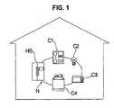
- FIG. 1illustrates an example of a home network system, which will be described below in detail.
- the manger of the home network systemcan control a plurality of electronic appliances connected to a home network N in a centralized way by transmitting control commands to the plurality of electronic appliances and receiving information about the execution results of the control commands through a different appliance such as a PC or a TV.
- Such a centralized control schemerequires a home server.
- the home serveris commonly built into an electronic appliance and an electronic appliance with a built-in home server is called a home server appliance.
- a home server applianceprocesses control signals sent to and received from a plurality of electronic appliances connected to the home network N (e.g., refrigerators and air conditioners).
- the home server applianceassigns a unique network address to an electronic appliance when the appliance is connected to the network for the first time.
- a client appliance(e.g., C1 ⁇ C4 shown in FIG. 1) has a microprocessor for executing a program for home networking and processes data exchanged through the home network N.
- the refrigeratoracts as the home server and a washing machine C4, a microwave oven C3, etc are connected to the home network as client appliances.
- the home server applianceassigns a unique network address to each of the client appliances when it is connected to the home network N for the first time so that the client appliances can be identified on the network.
- the home server appliancedetects the source of the signal based on the network address assigned to each of the plurality of client appliances.
- FIG. 2is a flow chart illustrating how a network address is assigned to a client appliance on the home network shown in FIG. 1.
- the client applianceWhen a client appliance hooks up to the home network N first, the client appliance transmits an address assignment request message to the home server appliance (S1). Receiving the address assignment request message, the home server appliance generates a unique network address (S2) and transmits the generated address to the client appliance (S3). Given the network address, the client appliance sets up its network address (S4) and transmits a confirmation message about the address setup to the home server appliance (S5), which completes the network address assignment process.
- the plurality of client appliancestransmit their respective address assignment request messages to the home server appliance almost simultaneously. For example, if the power to multiple air conditioners sharing power is turned on as they are physically connected to the home network N, the multiple air conditioners transmit address assignment request messages to the home server appliance almost simultaneously.
- the source address included in an address assignment request messagecomprises a product code indicating the product type and a logical address that is commonly set to 0 at factory. Because the air conditioners are of the same kind, they have the same product code and logical address, which means the source addresses included in the address assignment request messages are all identical. As a result, the home server appliance cannot identity the individual sources of the received address assignment request messages.
- the home server appliancegenerates and assigns only one network address to the plurality of client appliances that are indistinguishable on the home network. Consequently, the plurality of client appliances are assigned the same network address and the home server appliance has no means of individually controlling the plurality of client appliances on the home network.
- the userneeds to connect client appliances to the home network one by one so that the home server appliance can generate and assign a unique network address to each of the client appliances.
- the idea of connecting client appliances individuallyis a constraint on network management and is not feasible in some cases in which built-in electronic appliances sharing the same power input are used.
- a home server on the networkcommands the plurality of devices to generate a temporary address.
- the home serverassigns unique network addresses to the received temporary addresses and transmits the network addresses to the plurality of devices, thereby assigning a unique network address to each of the plurality of devices on the network.
- a home serverif a home server receives an address assignment request message, the home server waits from that point during a time interval that is longer than the period for the address assignment request message and shorter than double the period and determines that more than one device transmits address assignment request messages if two or more address assignment request messages having the same source address are received during the time interval.
- a network addresscomprises a product code and a logical address and the assignment of a unique network address is obtained by assigning a unique logical address.
- the range of temporary addressesis specified when a command for generating a temporary address is given to a plurality of devices.
- the command for generating temporary addressesare transmitted again to the devices that generated the identical address.
- FIG. 1illustrates a home network system established in a house
- FIG. 2illustrates a flow chart of a method of assigning a network address to a client appliance on the network shown in FIG. 1;
- FIG. 3illustrates a home network system embodying the present invention
- FIG. 4illustrates a flow chart of the method of assigning a unique network address to each of a plurality of devices on the home network in accordance with the present invention.
- FIG. 3shows a home network system wherein the present invention may be advantageously embodied, comprising a plurality of electronic appliances 200 1 , 200 2 , ⁇ , 200 k connected to a home network N established in a house and a home server 100 that assigns network addresses to the electronic appliances. If two or more address assignment request messages having the same source address are received (from the same appliance) during a predefined time interval after an address assignment request message was first received, the home server 100 transmits an address generation command message for commanding the generation of a temporary address to the electronic appliance.
- the home network N through which the plurality of electronic appliances 200 1 , 200 2 , ⁇ , 200 k and the home server 100 are connectedcan be a LAN such as Ethernet, a wireless communication network (LAN) using 2.5 GHz frequency, or a power line communication network providing data communication over existing power transmission and distribution networks.
- LANlocal area network
- Each of the electronic appliances 200 kincludes a communication module 210 K for sending/receiving messages to/from the home server 100 through the network N and a microprocessor 220 k for generating a temporary address and transmitting the generated address to the home server 100 when an address generation command message is received from the home server 100 through the communication module 210 k .
- the microprocessor 220 KWhen the electronic appliance 200 k is connected to the network N for the first time, the microprocessor 220 K generates an address assignment request message and transmits the message to the home server 100 through the communication module 210 K for requesting a unique network address.
- the address assignment request messageincludes a 2-byte source address (device address) comprising a 1-byte product code and a 1-byte logical address commonly set to 0x00 at factory.
- the home server 100includes a communication module 110 for exchanging messages with each of the client appliances 200 K and a microprocessor 120, responsive to an address assignment request message or a temporary address received through the communication module 110, for generating and assigning a network address or a part thereof (e.g., logical address).
- a communication module 110for exchanging messages with each of the client appliances 200 K and a microprocessor 120, responsive to an address assignment request message or a temporary address received through the communication module 110, for generating and assigning a network address or a part thereof (e.g., logical address).
- the home server 100waits for additional address assignment request messages to be received during a predefined time interval after that point. If an electronic appliance is connected to the network for the first time, the electronic appliance transmits an address assignment request message periodically with fixed period Taddr_req. The predefined time interval is set to a value between 1.5 ⁇ 2 times greater than the period for the address assignment request message (Taddr_req). If only one electronic appliance is connected to the network N, the home server 100 receives only one additional address assignment request message during the predefined time interval. Therefore, if two or more additional address assignment request messages having the same source device address are received after the initial request message, the microprocessor 120 of the home server 100 concludes that two or more electronic appliances of the same kind are connected to the network N.
- the microprocessor 120If it is determined that only one new device is connected to the network, the microprocessor 120 generates a logical address that is one greater than the last of the logical addresses that have been assigned to devices on the network so far and transmits the generated logical address to the device through the communication module 110. Receiving the logical address, the electronic appliance 200 sets up its network address by combining the received logical address with its own product code and transmits an address assignment completion message to the home server 100.
- the microprocessor 120 of the home server 100If two or more address assignment request messages having the same device address (e.g., 0x0A00) are received during the predefined time interval, the microprocessor 120 of the home server 100 generates an address generation command message destined for the device address (e.g., 0x0A00) when the predefined time interval expires in order to assign unique network addresses to the plurality of electronic appliances connected to the network N.
- the address generation command messageincludes the range of allowable addresses. The start address of the address range is set to the value one greater than the sum of the last of the logical addresses that have been assigned thus far (AdLast) and the number of devices that requested address assignment (Ld). The number of devices can be determined from the number of address assignment request messages received during the predefined time interval.
- the end address of the address rangeis set to the allowable maximum logical address.
- the logical addresses from AdLast+1 through AdLast+Ndwill be assigned to the devices that requested the address assignment and therefore are not allowed as temporary addresses. For example, if the last assigned logical address is 0x10, the range of allowable addresses is from 0x10+Nd+1 through 0xNNmax.
- each of two electronic appliances 200 1 and 200 2transmitted an address assignment request message having 0x0A00 as the source address (product code 0x0A and factory-set logical address 0x00) and then received an address generation command message transmitted by the home server 100.
- Each of the electronic appliances 200 1 and 200 2selects one logical address at random within the allowable address range included in the address generation command message, determines its temporary network address by combining the selected logical address with its own product code, and transmits the determined temporary address to the home server 100.
- the home server 100examines if the electronic appliances 200 1 and 200 2 transmitted the same temporary address. If so, the home server 100 retransmits an address generation command message to the received temporary address so that the electronic appliances 200 1 and 200 2 select their respective temporary addresses again. If the received temporary addresses are not identical, the home server 100 assigns sequential logical addresses starting from the next address of the last assigned logical address (e.g., 0x11) to the electronic appliances 200 1 and 200 2 and transmits the assigned logical addresses to the corresponding temporary addresses.
- the home server 100assigns sequential logical addresses starting from the next address of the last assigned logical address (e.g., 0x11) to the electronic appliances 200 1 and 200 2 and transmits the assigned logical addresses to the corresponding temporary addresses.
- the electronic appliances 200 1 and 200 2 of the same kindreceive 0x11 and 0x12 as their respective logical addresses and are assigned unique network addresses 0x0A11 and 0x0A12, respectively.
- the electronic appliances 200 1 and 200 2After setting their assigned network addresses, the electronic appliances 200 1 and 200 2 transmit address assignment completion messages to the home server 100. If the number of address assignment completion messages that the home server 100 receives is more than that of the logical addresses that the home server 100 assigned, it means that more than one device was assigned the same logical address. In this case, the home server 100 transmits the address generation command message again to the devices that transmitted the address assignment completion messages having the same network address so that the above procedure is repeated by the devices.
- FIG. 4illustrates the flowchart of the method of assigning unique network addresses to a plurality of devices on a home network system according to the present invention.
- An electronic appliance connected to a home network for the first timetransmits an address assignment request message to a home server (S11).
- the home serverIf the home server receives more than one additional address assignment request message from electronic appliances having the same network address comprising the same product code and logical address during the predefined time interval after the reception of the first address assignment request message (S12), the home server transmits an address generation command message to the network address (S13). If only one additional address assignment request message is received during the predefined time interval (S12), the home server generates one logical address and transmits it to the corresponding electronic appliance (S14).
- Each of a plurality of electronic appliances that receive the address generation command message from the home servergenerates a temporary address by selecting one address at random within the allowable address range specified by the address generation command message and transmits the temporary address to the home server (S15).
- the home serverreceives unique temporary addresses from the plurality of electronic appliances, the home server generates unique logical addresses corresponding to the received temporary addresses and transmits the logical addresses to the plurality of electronic appliances that transmitted the temporary addresses (S16).
- the plurality of electronic appliancesAfter receiving the logical addresses from the home server, the plurality of electronic appliances set up their respective network addresses and transmit address assignment completion messages back to the home server (S17). If the number of address assignment completion messages received by the home server exceeds the number of assigned logical addresses, it means that one address has been assigned to more than one device and steps S13 through S17 are repeated to assign network addresses again.
- the method of assigning network addresses to a plurality of devices on a home networkcan assign unique network addresses to electronic appliances sharing the same power automatically, which provides a more convenient network environment for users.
Landscapes
- Engineering & Computer Science (AREA)
- Computer Networks & Wireless Communication (AREA)
- Signal Processing (AREA)
- Automation & Control Theory (AREA)
- Small-Scale Networks (AREA)
Description
- The present invention relates to a network system and a method of assigning network addresses to devices in the network system and, more particularly, but not by way of limitation, to a method of automatically assigning unique network addresses to a plurality of electronic appliances of the same kind when the plurality of electronic applicanes are first connected to a home network and a home network system therefor.
- The document
WO 00/76174 A1 - The document
US 5,583,850 discloses a data communication system using a data link layer and medium access control of a packet message protocol wherein the quantity and capability of a plurality of stations requiring use of the medium at a given time cannot be predetermined. The conventional communication system comprises at least one commander station and at least one responder station which are coupled to a common medium by network interfaces, respectively. - The document
WO 03/055180 A1 - FIG. 1 illustrates an example of a home network system, which will be described below in detail.
- The manger of the home network system can control a plurality of electronic appliances connected to a home network N in a centralized way by transmitting control commands to the plurality of electronic appliances and receiving information about the execution results of the control commands through a different appliance such as a PC or a TV.
- Such a centralized control scheme requires a home server. The home server is commonly built into an electronic appliance and an electronic appliance with a built-in home server is called a home server appliance. A home server appliance processes control signals sent to and received from a plurality of electronic appliances connected to the home network N (e.g., refrigerators and air conditioners). In addition, the home server appliance assigns a unique network address to an electronic appliance when the appliance is connected to the network for the first time.
- The electronic appliances, which are identified on the network by their respective network addresses assigned by the home server appliance, are called client appliances. A client appliance (e.g., C1 ~ C4 shown in FIG. 1) has a microprocessor for executing a program for home networking and processes data exchanged through the home network N.
- In the home network system shown in FIG. 1, the refrigerator acts as the home server and a washing machine C4, a microwave oven C3, etc are connected to the home network as client appliances.
- To control a plurality of client appliances through the home network, the home server appliance assigns a unique network address to each of the client appliances when it is connected to the home network N for the first time so that the client appliances can be identified on the network. When receiving a control signal or a control result through the network, the home server appliance detects the source of the signal based on the network address assigned to each of the plurality of client appliances.
- FIG. 2 is a flow chart illustrating how a network address is assigned to a client appliance on the home network shown in FIG. 1. When a client appliance hooks up to the home network N first, the client appliance transmits an address assignment request message to the home server appliance (S1). Receiving the address assignment request message, the home server appliance generates a unique network address (S2) and transmits the generated address to the client appliance (S3). Given the network address, the client appliance sets up its network address (S4) and transmits a confirmation message about the address setup to the home server appliance (S5), which completes the network address assignment process.
- If a plurality of client appliances of the same kind are connected to the home network N at the same time, the plurality of client appliances transmit their respective address assignment request messages to the home server appliance almost simultaneously. For example, if the power to multiple air conditioners sharing power is turned on as they are physically connected to the home network N, the multiple air conditioners transmit address assignment request messages to the home server appliance almost simultaneously. The source address included in an address assignment request message comprises a product code indicating the product type and a logical address that is commonly set to 0 at factory. Because the air conditioners are of the same kind, they have the same product code and logical address, which means the source addresses included in the address assignment request messages are all identical. As a result, the home server appliance cannot identity the individual sources of the received address assignment request messages.
- The home server appliance generates and assigns only one network address to the plurality of client appliances that are indistinguishable on the home network. Consequently, the plurality of client appliances are assigned the same network address and the home server appliance has no means of individually controlling the plurality of client appliances on the home network.
- To avoid this problem, the user needs to connect client appliances to the home network one by one so that the home server appliance can generate and assign a unique network address to each of the client appliances. The idea of connecting client appliances individually, however, is a constraint on network management and is not feasible in some cases in which built-in electronic appliances sharing the same power input are used.
- In view of the shortcomings of the prior art, it is an object of the present invention to provide a method according to claim 12 of identifying a plurality of electronic appliances connected to a network for the first time and simultaneously and assigning a unique network address to each of the plurality of electronic appliances and a home network system for implementing the method according to
claim 1. - In the method of assigning network addresses to a plurality of devices on a home network according to the present invention, if it is determined that address assignment request messages are received from a plurality of devices, a home server on the network commands the plurality of devices to generate a temporary address. Receiving temporary addresses generated by the plurality of devices, the home server assigns unique network addresses to the received temporary addresses and transmits the network addresses to the plurality of devices, thereby assigning a unique network address to each of the plurality of devices on the network.
- In one embodiment of the invention, if a home server receives an address assignment request message, the home server waits from that point during a time interval that is longer than the period for the address assignment request message and shorter than double the period and determines that more than one device transmits address assignment request messages if two or more address assignment request messages having the same source address are received during the time interval.
- In another embodiment, a network address comprises a product code and a logical address and the assignment of a unique network address is obtained by assigning a unique logical address.
- In still another embodiment, the range of temporary addresses is specified when a command for generating a temporary address is given to a plurality of devices.
- In yet another embodiment, if some of the temporary addresses generated according to a command for generating temporary addresses are identical, the command for generating temporary addresses are transmitted again to the devices that generated the identical address.
- In a further embodiment, if the number of address setup confirmation messages received after unique network addresses are assigned to a plurality of temporary addresses using temporary addresses is not the same as the number of the assigned network addresses, the process of address assignment is executed again.
- The above features and other advantages of the present invention will be more clearly understood from the following detailed description taken in conjunction with the accompanying drawings, in which:
- FIG. 1 illustrates a home network system established in a house;
- FIG. 2 illustrates a flow chart of a method of assigning a network address to a client appliance on the network shown in FIG. 1;
- FIG. 3 illustrates a home network system embodying the present invention; and
- FIG. 4 illustrates a flow chart of the method of assigning a unique network address to each of a plurality of devices on the home network in accordance with the present invention.
- In order that the invention may be fully understood, preferred embodiments thereof will now be described with reference to the accompanying drawings.
- FIG. 3 shows a home network system wherein the present invention may be advantageously embodied, comprising a plurality of electronic appliances 2001, 2002, ···, 200k connected to a home network N established in a house and a
home server 100 that assigns network addresses to the electronic appliances. If two or more address assignment request messages having the same source address are received (from the same appliance) during a predefined time interval after an address assignment request message was first received, thehome server 100 transmits an address generation command message for commanding the generation of a temporary address to the electronic appliance. - The home network N through which the plurality of electronic appliances 2001, 2002, ···, 200k and the
home server 100 are connected can be a LAN such as Ethernet, a wireless communication network (LAN) using 2.5 GHz frequency, or a power line communication network providing data communication over existing power transmission and distribution networks. - Each of the electronic appliances 200k includes a communication module 210K for sending/receiving messages to/from the
home server 100 through the network N and a microprocessor 220k for generating a temporary address and transmitting the generated address to thehome server 100 when an address generation command message is received from thehome server 100 through the communication module 210k. When the electronic appliance 200k is connected to the network N for the first time, the microprocessor 220K generates an address assignment request message and transmits the message to thehome server 100 through the communication module 210K for requesting a unique network address. The address assignment request message includes a 2-byte source address (device address) comprising a 1-byte product code and a 1-byte logical address commonly set to 0x00 at factory. - The
home server 100 includes acommunication module 110 for exchanging messages with each of the client appliances 200K and amicroprocessor 120, responsive to an address assignment request message or a temporary address received through thecommunication module 110, for generating and assigning a network address or a part thereof (e.g., logical address). - If an address assignment request message is received from the electronic appliance 200K, the
home server 100 waits for additional address assignment request messages to be received during a predefined time interval after that point. If an electronic appliance is connected to the network for the first time, the electronic appliance transmits an address assignment request message periodically with fixed period Taddr_req. The predefined time interval is set to a value between 1.5 ~ 2 times greater than the period for the address assignment request message (Taddr_req). If only one electronic appliance is connected to the network N, thehome server 100 receives only one additional address assignment request message during the predefined time interval. Therefore, if two or more additional address assignment request messages having the same source device address are received after the initial request message, themicroprocessor 120 of thehome server 100 concludes that two or more electronic appliances of the same kind are connected to the network N. - If it is determined that only one new device is connected to the network, the
microprocessor 120 generates a logical address that is one greater than the last of the logical addresses that have been assigned to devices on the network so far and transmits the generated logical address to the device through thecommunication module 110. Receiving the logical address, the electronic appliance 200 sets up its network address by combining the received logical address with its own product code and transmits an address assignment completion message to thehome server 100. - If two or more address assignment request messages having the same device address (e.g., 0x0A00) are received during the predefined time interval, the
microprocessor 120 of thehome server 100 generates an address generation command message destined for the device address (e.g., 0x0A00) when the predefined time interval expires in order to assign unique network addresses to the plurality of electronic appliances connected to the network N. The address generation command message includes the range of allowable addresses. The start address of the address range is set to the value one greater than the sum of the last of the logical addresses that have been assigned thus far (AdLast) and the number of devices that requested address assignment (Ld). The number of devices can be determined from the number of address assignment request messages received during the predefined time interval. The end address of the address range is set to the allowable maximum logical address. The logical addresses from AdLast+1 through AdLast+Nd will be assigned to the devices that requested the address assignment and therefore are not allowed as temporary addresses. For example, if the last assigned logical address is 0x10, the range of allowable addresses is from 0x10+Nd+1 through 0xNNmax. - For simplicity, suppose that each of two electronic appliances 2001 and 2002 transmitted an address assignment request message having 0x0A00 as the source address (product code 0x0A and factory-set logical address 0x00) and then received an address generation command message transmitted by the
home server 100. - Each of the electronic appliances 2001 and 2002 selects one logical address at random within the allowable address range included in the address generation command message, determines its temporary network address by combining the selected logical address with its own product code, and transmits the determined temporary address to the
home server 100. Thehome server 100 examines if the electronic appliances 2001 and 2002 transmitted the same temporary address. If so, thehome server 100 retransmits an address generation command message to the received temporary address so that the electronic appliances 2001 and 2002 select their respective temporary addresses again. If the received temporary addresses are not identical, thehome server 100 assigns sequential logical addresses starting from the next address of the last assigned logical address (e.g., 0x11) to the electronic appliances 2001 and 2002 and transmits the assigned logical addresses to the corresponding temporary addresses. - As a result, the electronic appliances 2001 and 2002 of the same kind receive 0x11 and 0x12 as their respective logical addresses and are assigned unique network addresses 0x0A11 and 0x0A12, respectively.
- After setting their assigned network addresses, the electronic appliances 2001 and 2002 transmit address assignment completion messages to the
home server 100. If the number of address assignment completion messages that thehome server 100 receives is more than that of the logical addresses that thehome server 100 assigned, it means that more than one device was assigned the same logical address. In this case, thehome server 100 transmits the address generation command message again to the devices that transmitted the address assignment completion messages having the same network address so that the above procedure is repeated by the devices. - FIG. 4 illustrates the flowchart of the method of assigning unique network addresses to a plurality of devices on a home network system according to the present invention.
- An electronic appliance connected to a home network for the first time transmits an address assignment request message to a home server (S11).
- If the home server receives more than one additional address assignment request message from electronic appliances having the same network address comprising the same product code and logical address during the predefined time interval after the reception of the first address assignment request message (S12), the home server transmits an address generation command message to the network address (S13). If only one additional address assignment request message is received during the predefined time interval (S12), the home server generates one logical address and transmits it to the corresponding electronic appliance (S14).
- Each of a plurality of electronic appliances that receive the address generation command message from the home server generates a temporary address by selecting one address at random within the allowable address range specified by the address generation command message and transmits the temporary address to the home server (S15).
- Receiving unique temporary addresses from the plurality of electronic appliances, the home server generates unique logical addresses corresponding to the received temporary addresses and transmits the logical addresses to the plurality of electronic appliances that transmitted the temporary addresses (S16).
- After receiving the logical addresses from the home server, the plurality of electronic appliances set up their respective network addresses and transmit address assignment completion messages back to the home server (S17). If the number of address assignment completion messages received by the home server exceeds the number of assigned logical addresses, it means that one address has been assigned to more than one device and steps S13 through S17 are repeated to assign network addresses again.
- The method of assigning network addresses to a plurality of devices on a home network according to the present invention can assign unique network addresses to electronic appliances sharing the same power automatically, which provides a more convenient network environment for users.
- While the invention has been disclosed with respect to a limited number of embodiments, those skilled in the art, having the benefit of this disclosure, will appreciate numerous modifications and variations therefrom.
Claims (22)
- A network system to which a plurality of devices are connected, the network system comprising:- a home server (100);- a network (N); and- at least one device (200K) configured to transmit an address assignment request message to the home server (100) when it is connected to the network (N);wherein the home server (100) is configured to determine if address assignment request messages, received from a plurality of devices (200K) during a time interval, have some source address and to command the plurality of devices (200K) to generate temporary addresses, if it is determined that the address assignment request messages have a same source address;
wherein the at least one device (200K) is configured to generate and transmit a temporary address to the home server (100), if it is determined by the home server (100) that the address assignment request messages have a same source address; and
wherein the home server (100) is configured to receive the generated temporary addresses and to assign unique network addresses to the plurality of devices (200K) respectively by transmitting a message for assigning an unique address to each of the received temporary addresses. - The network system set forth in claim 1, wherein the at least one device (200K) is configured to transmit the address assignment request message periodically with a fixed period (Taddr_reg) after it is connected to the network (N).
- The network system set forth in claim 2, wherein if the home server (100) receives an address assignment request message, the home server (100) is configured to wait from that point during a time interval that is longer than the fixed period (Taddr_reg) for the address assignment request message and shorter than double the fixed period (Taddr_reg) and to determine that more than one device (200K) transmits address assignment request messages if two or more address assignment request messages having the same source address are received during the time interval.
- The network system set forth in claim 1, wherein the address assignment request message transmitted by the at least one device (200K) to the home server (100) has a network address comprising a factory-set product code and a factory-set logical address as its source address.
- The network system set forth in claim 4, wherein the home server (100) is configured to assign unique network addresses to the plurality of devices (200K) by assigning an unique logical address to the factory-set logical address of each of the plurality of devices (200K).
- The network system set forth in claim 1, wherein the home server (100) is configured to specify the range of allowable temporary addresses when the home server (100) commands the plurality of devices (200K) to generate temporary addresses.
- The network system set forth in claim 6, wherein addresses included in the specified range are greater than the sum of the last address among addresses that have been assigned thus far and the number of the plurality of devices (200K).
- The network system set forth in claim 7, wherein the number of the plurality of devices (200K) is determined based on the number of address assignment request messages received during a predefined time interval after the reception of the initial address assignment request message.
- The network system set forth in claim 7, wherein the home server (100) is configured to assign sequential network addresses corresponding to the generated temporary addresses to the plurality of devices (200K), the sequential network address starting from the address one greater than the last address.
- The network system set forth in claim 1, wherein if some of the temporary addresses generated according to the command for generating temporary addresses are identical, the home server (100) is configured to retransmit the command for generating temporary addresses to the identical temporary address.
- The network system set forth in claim 1, wherein if the number of address setup confirmation messages received after the home server (100) transmits the network addresses corresponding to the temporary addresses to the plurality of devices (200K) is not the same as the number of the assigned network addresses, the home server (100) is configured to retransmit the command for generating temporary addresses to a part or all of the plurality of devices (200K).
- A method of assigning network addresses to devices (200K) connected to a network (N) established in a house, conducted by a home server (100), said method comprising the steps of:(a) determining if address assignment request messages, received from a plurality of devices (200K) during a time interval, have some source address;(b) commanding the plurality of devices (200K) to generate temporary addresses and then receiving the generated temporary addresses, if it is determined that the address assignment request messages have a same source address; and(c) assigning unique network addresses to the plurality of devices (200K) respectively by transmitting a message for assigning an unique address to each of the received temporary addresses.
- The method set forth in claim 12, wherein the plurality of devices (200K) transmit the address assignment request messages periodically with a fixed period (Taddr_reg) after the plurality of devices (200K) are connected to the network (N).
- The method set forth in claim 13, wherein if an address assignment request message is received, the step (a) waits from that point during a time interval that is longer than the fixed period (Taddr_reg) for the address assignment request messages and shorter than double the fixed period (Taddr_reg) and determines that a plurality of devices (200K) transmit the address assignment request messages if two ore more address assignment request messages having the same source address are received during the time interval.
- The method set forth in claim 12, wherein each of the address assignment request messages transmitted by the plurality of devices (200K) to the home server (100) has a network address comprising a factory-set product code and factory-set logical address as its source address.
- The method set forth in claim 15, wherein the step (c) assigns unique network addresses to the plurality of devices (200K) by assigning an unique address to the factory-set logical address of each of the plurality of devices (200K).
- The method set forth in claim 12, wherein the step (b) specifies the range of allowable temporary addresses when commanding the plurality of devices (200K) to generate temporary addresses.
- The method set forth in claim 17, wherein addresses included in the specified range are greater than the sum of the last address among addresses that have been assigned thus far and the number of the plurality of devices (200K).
- The method set forth in claim 18, wherein the number of the plurality of devices (200K) is determined based on the number of address assignment request messages received during a predefined time interval after the reception of the initial address assignment request message.
- The method set forth in claim 18, wherein the step (c) assigns sequential network addresses corresponding to the received temporary addresses to the plurality of devices (200K), the network addresses starting from the address one greater than the last address.
- The method set forth in claim 12, wherein if some of the received temporary addresses are identical, the step (c) does not assign addresses and retransmits the command for generating temporary addresses to the identical temporary address.
- The method set forth in claim 12, further comprising the step of:(d) retransmitting the command for generating temporary addresses to a part or all of the plurality of devices (200K) if the number of address setup confirmation messages received after the step (c) is not the same as the number of the assigned network addresses.
Applications Claiming Priority (2)
| Application Number | Priority Date | Filing Date | Title |
|---|---|---|---|
| KR2004012577 | 2004-02-25 | ||
| KR1020040012577AKR100633666B1 (en) | 2004-02-25 | 2004-02-25 | Home network system and its control method |
Publications (2)
| Publication Number | Publication Date |
|---|---|
| EP1569419A1 EP1569419A1 (en) | 2005-08-31 |
| EP1569419B1true EP1569419B1 (en) | 2008-01-02 |
Family
ID=34747940
Family Applications (1)
| Application Number | Title | Priority Date | Filing Date |
|---|---|---|---|
| EP05003790ACeasedEP1569419B1 (en) | 2004-02-25 | 2005-02-22 | Method of assigning addresses to a plurality of devices on a network and a network system therefor |
Country Status (5)
| Country | Link |
|---|---|
| US (1) | US7564804B2 (en) |
| EP (1) | EP1569419B1 (en) |
| KR (1) | KR100633666B1 (en) |
| CN (1) | CN1662014A (en) |
| DE (1) | DE602005004047T2 (en) |
Families Citing this family (34)
| Publication number | Priority date | Publication date | Assignee | Title |
|---|---|---|---|---|
| DE102005004151A1 (en)* | 2005-01-28 | 2006-08-10 | Siemens Ag | Method and device for assigning packet addresses of a plurality of devices |
| US8584194B1 (en)* | 2005-08-29 | 2013-11-12 | Crimson Corporation | Network access control using a quarantined server |
| JP4584809B2 (en)* | 2005-10-04 | 2010-11-24 | パナソニック株式会社 | Control device and controlled device |
| US8090807B2 (en)* | 2006-01-23 | 2012-01-03 | Lg Electronics Inc. | Home code setting method for home network system |
| CN100366018C (en)* | 2006-01-26 | 2008-01-30 | 华为技术有限公司 | A method for realizing interconnection of communication units |
| JP3979436B1 (en)* | 2006-03-09 | 2007-09-19 | ダイキン工業株式会社 | Air conditioner and address setting method in air conditioner |
| US7755505B2 (en)* | 2006-09-06 | 2010-07-13 | Lutron Electronics Co., Inc. | Procedure for addressing remotely-located radio frequency components of a control system |
| US7719961B2 (en)* | 2006-09-29 | 2010-05-18 | Rockwell Automation Technologies, Inc. | Industrial ethernet communications adapter |
| US8260366B2 (en) | 2007-09-28 | 2012-09-04 | At&T Intellectual Property I, Lp | Automatic setting of an alert mode on a wireless device |
| US8914133B2 (en)* | 2009-12-17 | 2014-12-16 | Lg Electronics Inc. | Power management system and method of controlling network system |
| KR20110101368A (en)* | 2010-03-08 | 2011-09-16 | 엘지전자 주식회사 | Air Conditioning System and Control Method |
| WO2012157017A1 (en)* | 2011-05-16 | 2012-11-22 | Hitachi, Ltd. | Computer system for allocating ip address to communication apparatus in computer subsystem newly added and method for newly adding computer subsystem to computer system |
| US9143197B2 (en) | 2011-10-18 | 2015-09-22 | Texas Instruments Incorporated | Joining process for G3 networks |
| WO2014016968A1 (en)* | 2012-07-27 | 2014-01-30 | 三菱電機株式会社 | Communication adaptor, controller, and network system |
| GB2528607B (en)* | 2013-05-22 | 2020-12-23 | Mitsubishi Electric Corp | Monitoring system, facility management device, monitoring method, and program |
| GB2520931A (en)* | 2013-11-29 | 2015-06-10 | Togeva Ltd | A system for managing communications with a plurality of mobile devices |
| CN106292560B (en)* | 2015-05-26 | 2018-07-13 | 美的集团股份有限公司 | The communication means and appliance system of appliance system |
| KR101920190B1 (en)* | 2016-11-22 | 2019-02-08 | 한국인터넷진흥원 | A method and apparatus for generating a random ip |
| US10326732B1 (en)* | 2018-10-08 | 2019-06-18 | Quest Automated Services, LLC | Automation system with address generation |
| CN109491943B (en)* | 2018-10-29 | 2021-01-01 | 科华恒盛股份有限公司 | Module address allocation method, system, modular device and storage medium |
| PL3688636T3 (en) | 2018-12-03 | 2023-09-11 | Hewlett-Packard Development Company, L.P. | Logic circuitry |
| EP3687797A1 (en) | 2018-12-03 | 2020-08-05 | Hewlett-Packard Development Company, L.P. | Logic circuitry |
| AU2018452257B2 (en) | 2018-12-03 | 2022-12-01 | Hewlett-Packard Development Company, L.P. | Logic circuitry |
| ES2848998T3 (en) | 2018-12-03 | 2021-08-13 | Hewlett Packard Development Co | Logic circuits |
| WO2021080607A1 (en) | 2019-10-25 | 2021-04-29 | Hewlett-Packard Development Company, L.P. | Logic circuitry package |
| KR20210087502A (en)* | 2018-12-03 | 2021-07-12 | 휴렛-팩커드 디벨롭먼트 컴퍼니, 엘.피. | logic circuit |
| CN113168446A (en) | 2018-12-03 | 2021-07-23 | 惠普发展公司,有限责任合伙企业 | Logic circuitry packaging |
| US11366913B2 (en) | 2018-12-03 | 2022-06-21 | Hewlett-Packard Development Company, L.P. | Logic circuitry |
| CN113165391A (en) | 2018-12-03 | 2021-07-23 | 惠普发展公司,有限责任合伙企业 | Logic circuit |
| US11338586B2 (en) | 2018-12-03 | 2022-05-24 | Hewlett-Packard Development Company, L.P. | Logic circuitry |
| CN110932980B (en)* | 2019-11-27 | 2022-09-20 | 达闼机器人股份有限公司 | Communication method, terminal, and computer-readable storage medium |
| US11218360B2 (en)* | 2019-12-09 | 2022-01-04 | Quest Automated Services, LLC | Automation system with edge computing |
| EP4031997A1 (en) | 2020-04-30 | 2022-07-27 | Hewlett-Packard Development Company, L.P. | Logic circuitry package for print apparatus |
| CN116599842B (en)* | 2023-07-17 | 2023-09-19 | 北京中科睿信科技有限公司 | Multi-module array system management method, equipment and medium |
Family Cites Families (12)
| Publication number | Priority date | Publication date | Assignee | Title |
|---|---|---|---|---|
| US5365551A (en)* | 1992-12-15 | 1994-11-15 | Micron Technology, Inc. | Data communication transceiver using identification protocol |
| JPH11275119A (en) | 1998-03-19 | 1999-10-08 | Toshiba Tec Corp | Terminal communication address duplication detection method and device |
| KR100275707B1 (en)* | 1998-11-26 | 2000-12-15 | 윤종용 | Home networl system and node id assignment method thereof |
| WO2000076174A1 (en)* | 1999-06-08 | 2000-12-14 | Panja, Inc. | Method and system for dynamically assigning device numbers in a control system |
| JP3534305B2 (en)* | 2000-02-29 | 2004-06-07 | 日本電気株式会社 | IP address duplication detection method using address resolution protocol |
| CN100337461C (en)* | 2000-03-17 | 2007-09-12 | 美国在线服务公司 | System and method for home networking |
| US7349967B2 (en)* | 2000-07-21 | 2008-03-25 | Samsung Electronics Co., Ltd. | Architecture for home network on world wide web with private-public IP address/URL mapping |
| US7617317B2 (en)* | 2001-12-03 | 2009-11-10 | Sprint Spectrum L.P. | Method and system for allowing multiple service providers to serve users via a common access network |
| GB0130531D0 (en)* | 2001-12-20 | 2002-02-06 | Marconi Comm Ltd | Duplicate address detection in networks |
| FI113515B (en)* | 2002-01-18 | 2004-04-30 | Nokia Corp | Addressing in wireless LANs |
| KR100878764B1 (en)* | 2002-07-06 | 2009-01-14 | 삼성전자주식회사 | Wireless LAN System for User Anonymity Guarantee and User Anonymity Guarantee Method |
| JP2004048175A (en)* | 2002-07-09 | 2004-02-12 | Toshiba Corp | Communication device, communication system and communication method |
- 2004
- 2004-02-25KRKR1020040012577Apatent/KR100633666B1/ennot_activeExpired - Fee Related
- 2005
- 2005-02-22DEDE602005004047Tpatent/DE602005004047T2/ennot_activeExpired - Fee Related
- 2005-02-22EPEP05003790Apatent/EP1569419B1/ennot_activeCeased
- 2005-02-24USUS11/065,964patent/US7564804B2/enactiveActive
- 2005-02-25CNCN2005100087434Apatent/CN1662014A/enactivePending
Also Published As
| Publication number | Publication date |
|---|---|
| CN1662014A (en) | 2005-08-31 |
| DE602005004047T2 (en) | 2008-04-10 |
| EP1569419A1 (en) | 2005-08-31 |
| US20050185595A1 (en) | 2005-08-25 |
| DE602005004047D1 (en) | 2008-02-14 |
| KR20050086181A (en) | 2005-08-30 |
| US7564804B2 (en) | 2009-07-21 |
| KR100633666B1 (en) | 2006-10-12 |
Similar Documents
| Publication | Publication Date | Title |
|---|---|---|
| EP1569419B1 (en) | Method of assigning addresses to a plurality of devices on a network and a network system therefor | |
| US8374104B2 (en) | Simple installation of devices on a network | |
| US7032018B2 (en) | Home appliance networking system and method for controlling the same | |
| US6463473B1 (en) | Configuring a wireless computer network to allow automatic access by a guest client device | |
| US8094655B2 (en) | Communication scheme with arbitration mechanism for cases of address initialization and server setting | |
| US7430591B2 (en) | Methods and arrangements for configuring functional networks | |
| KR100488205B1 (en) | Communication device and communication control method using efficient echonet address determination scheme | |
| US8484323B2 (en) | Network system connected with multiple master devices and method for operating the same | |
| KR20040050476A (en) | Home Network System and Home Appliance Reducing Method for the Same | |
| US8819193B2 (en) | Method of setting network, server apparatus using the method, and network system including the server apparatus | |
| CN112311633A (en) | Distribution network control method, distribution network control device, household appliance and storage medium | |
| US20030018703A1 (en) | Smart appliance network system and communication protocol | |
| CN117917048A (en) | Method, device, equipment and storage medium for configuring bridging equipment | |
| CN102301654B (en) | Network system | |
| EP1892928B1 (en) | Remote management apparatus and method of setting IP address | |
| KR100504610B1 (en) | Method for Setting Home Code of Home Network System | |
| KR100565499B1 (en) | How to plug in the master device | |
| CN101926130B (en) | Method and system for controlling communication network | |
| WO2006091039A1 (en) | Network control protocol device and network connection method | |
| KR20020084882A (en) | Home Appliance Networking System and Method for the same | |
| KR100773678B1 (en) | Terminal for forming a virtual network | |
| CN101164294A (en) | Network control protocol device and net connecting method thereof | |
| Lee et al. | The Implementation of EIA 709.1 Standard Protocol Based Home Control System Architecture having Network Configuration Function |
Legal Events
| Date | Code | Title | Description |
|---|---|---|---|
| PUAI | Public reference made under article 153(3) epc to a published international application that has entered the european phase | Free format text:ORIGINAL CODE: 0009012 | |
| AK | Designated contracting states | Kind code of ref document:A1 Designated state(s):AT BE BG CH CY CZ DE DK EE ES FI FR GB GR HU IE IS IT LI LT LU MC NL PL PT RO SE SI SK TR | |
| AX | Request for extension of the european patent | Extension state:AL BA HR LV MK YU | |
| 17P | Request for examination filed | Effective date:20060104 | |
| AKX | Designation fees paid | Designated state(s):DE GB | |
| GRAP | Despatch of communication of intention to grant a patent | Free format text:ORIGINAL CODE: EPIDOSNIGR1 | |
| GRAS | Grant fee paid | Free format text:ORIGINAL CODE: EPIDOSNIGR3 | |
| GRAA | (expected) grant | Free format text:ORIGINAL CODE: 0009210 | |
| AK | Designated contracting states | Kind code of ref document:B1 Designated state(s):DE GB | |
| REG | Reference to a national code | Ref country code:GB Ref legal event code:FG4D | |
| REF | Corresponds to: | Ref document number:602005004047 Country of ref document:DE Date of ref document:20080214 Kind code of ref document:P | |
| PGFP | Annual fee paid to national office [announced via postgrant information from national office to epo] | Ref country code:DE Payment date:20080216 Year of fee payment:4 | |
| PLBE | No opposition filed within time limit | Free format text:ORIGINAL CODE: 0009261 | |
| STAA | Information on the status of an ep patent application or granted ep patent | Free format text:STATUS: NO OPPOSITION FILED WITHIN TIME LIMIT | |
| 26N | No opposition filed | Effective date:20081003 | |
| GBPC | Gb: european patent ceased through non-payment of renewal fee | Effective date:20090222 | |
| PG25 | Lapsed in a contracting state [announced via postgrant information from national office to epo] | Ref country code:DE Free format text:LAPSE BECAUSE OF NON-PAYMENT OF DUE FEES Effective date:20090901 | |
| PG25 | Lapsed in a contracting state [announced via postgrant information from national office to epo] | Ref country code:GB Free format text:LAPSE BECAUSE OF NON-PAYMENT OF DUE FEES Effective date:20090222 |