EP1568333B1 - Endoscopic system using an extremely fine composite optical fiber - Google Patents
Endoscopic system using an extremely fine composite optical fiberDownload PDFInfo
- Publication number
- EP1568333B1 EP1568333B1EP05003877AEP05003877AEP1568333B1EP 1568333 B1EP1568333 B1EP 1568333B1EP 05003877 AEP05003877 AEP 05003877AEP 05003877 AEP05003877 AEP 05003877AEP 1568333 B1EP1568333 B1EP 1568333B1
- Authority
- EP
- European Patent Office
- Prior art keywords
- optical fiber
- image
- laser
- fiber
- diameter
- Prior art date
- Legal status (The legal status is an assumption and is not a legal conclusion. Google has not performed a legal analysis and makes no representation as to the accuracy of the status listed.)
- Expired - Lifetime
Links
Images


Classifications
- A—HUMAN NECESSITIES
- A61—MEDICAL OR VETERINARY SCIENCE; HYGIENE
- A61B—DIAGNOSIS; SURGERY; IDENTIFICATION
- A61B18/00—Surgical instruments, devices or methods for transferring non-mechanical forms of energy to or from the body
- A61B18/18—Surgical instruments, devices or methods for transferring non-mechanical forms of energy to or from the body by applying electromagnetic radiation, e.g. microwaves
- A61B18/20—Surgical instruments, devices or methods for transferring non-mechanical forms of energy to or from the body by applying electromagnetic radiation, e.g. microwaves using laser
- A61B18/22—Surgical instruments, devices or methods for transferring non-mechanical forms of energy to or from the body by applying electromagnetic radiation, e.g. microwaves using laser the beam being directed along or through a flexible conduit, e.g. an optical fibre; Couplings or hand-pieces therefor
- A—HUMAN NECESSITIES
- A61—MEDICAL OR VETERINARY SCIENCE; HYGIENE
- A61B—DIAGNOSIS; SURGERY; IDENTIFICATION
- A61B1/00—Instruments for performing medical examinations of the interior of cavities or tubes of the body by visual or photographical inspection, e.g. endoscopes; Illuminating arrangements therefor
- A61B1/00163—Optical arrangements
- A61B1/00165—Optical arrangements with light-conductive means, e.g. fibre optics
- A61B1/00167—Details of optical fibre bundles, e.g. shape or fibre distribution
- A—HUMAN NECESSITIES
- A61—MEDICAL OR VETERINARY SCIENCE; HYGIENE
- A61B—DIAGNOSIS; SURGERY; IDENTIFICATION
- A61B1/00—Instruments for performing medical examinations of the interior of cavities or tubes of the body by visual or photographical inspection, e.g. endoscopes; Illuminating arrangements therefor
- A61B1/00163—Optical arrangements
- A61B1/00165—Optical arrangements with light-conductive means, e.g. fibre optics
- A61B1/0017—Details of single optical fibres, e.g. material or cladding
- A—HUMAN NECESSITIES
- A61—MEDICAL OR VETERINARY SCIENCE; HYGIENE
- A61B—DIAGNOSIS; SURGERY; IDENTIFICATION
- A61B1/00—Instruments for performing medical examinations of the interior of cavities or tubes of the body by visual or photographical inspection, e.g. endoscopes; Illuminating arrangements therefor
- A61B1/06—Instruments for performing medical examinations of the interior of cavities or tubes of the body by visual or photographical inspection, e.g. endoscopes; Illuminating arrangements therefor with illuminating arrangements
- A61B1/07—Instruments for performing medical examinations of the interior of cavities or tubes of the body by visual or photographical inspection, e.g. endoscopes; Illuminating arrangements therefor with illuminating arrangements using light-conductive means, e.g. optical fibres
- A—HUMAN NECESSITIES
- A61—MEDICAL OR VETERINARY SCIENCE; HYGIENE
- A61B—DIAGNOSIS; SURGERY; IDENTIFICATION
- A61B90/00—Instruments, implements or accessories specially adapted for surgery or diagnosis and not covered by any of the groups A61B1/00 - A61B50/00, e.g. for luxation treatment or for protecting wound edges
- A61B90/30—Devices for illuminating a surgical field, the devices having an interrelation with other surgical devices or with a surgical procedure
- A—HUMAN NECESSITIES
- A61—MEDICAL OR VETERINARY SCIENCE; HYGIENE
- A61B—DIAGNOSIS; SURGERY; IDENTIFICATION
- A61B90/00—Instruments, implements or accessories specially adapted for surgery or diagnosis and not covered by any of the groups A61B1/00 - A61B50/00, e.g. for luxation treatment or for protecting wound edges
- A61B90/36—Image-producing devices or illumination devices not otherwise provided for
- A61B90/37—Surgical systems with images on a monitor during operation
- G—PHYSICS
- G02—OPTICS
- G02B—OPTICAL ELEMENTS, SYSTEMS OR APPARATUS
- G02B23/00—Telescopes, e.g. binoculars; Periscopes; Instruments for viewing the inside of hollow bodies; Viewfinders; Optical aiming or sighting devices
- G02B23/24—Instruments or systems for viewing the inside of hollow bodies, e.g. fibrescopes
- G02B23/2407—Optical details
- G02B23/2461—Illumination
- G02B23/2469—Illumination using optical fibres
- G—PHYSICS
- G02—OPTICS
- G02B—OPTICAL ELEMENTS, SYSTEMS OR APPARATUS
- G02B23/00—Telescopes, e.g. binoculars; Periscopes; Instruments for viewing the inside of hollow bodies; Viewfinders; Optical aiming or sighting devices
- G02B23/24—Instruments or systems for viewing the inside of hollow bodies, e.g. fibrescopes
- G02B23/26—Instruments or systems for viewing the inside of hollow bodies, e.g. fibrescopes using light guides
- A—HUMAN NECESSITIES
- A61—MEDICAL OR VETERINARY SCIENCE; HYGIENE
- A61B—DIAGNOSIS; SURGERY; IDENTIFICATION
- A61B18/00—Surgical instruments, devices or methods for transferring non-mechanical forms of energy to or from the body
- A61B18/18—Surgical instruments, devices or methods for transferring non-mechanical forms of energy to or from the body by applying electromagnetic radiation, e.g. microwaves
- A61B18/20—Surgical instruments, devices or methods for transferring non-mechanical forms of energy to or from the body by applying electromagnetic radiation, e.g. microwaves using laser
- A61B18/22—Surgical instruments, devices or methods for transferring non-mechanical forms of energy to or from the body by applying electromagnetic radiation, e.g. microwaves using laser the beam being directed along or through a flexible conduit, e.g. an optical fibre; Couplings or hand-pieces therefor
- A61B2018/2205—Characteristics of fibres
- A61B2018/2211—Plurality of fibres
- A—HUMAN NECESSITIES
- A61—MEDICAL OR VETERINARY SCIENCE; HYGIENE
- A61B—DIAGNOSIS; SURGERY; IDENTIFICATION
- A61B18/00—Surgical instruments, devices or methods for transferring non-mechanical forms of energy to or from the body
- A61B18/18—Surgical instruments, devices or methods for transferring non-mechanical forms of energy to or from the body by applying electromagnetic radiation, e.g. microwaves
- A61B18/20—Surgical instruments, devices or methods for transferring non-mechanical forms of energy to or from the body by applying electromagnetic radiation, e.g. microwaves using laser
- A61B18/22—Surgical instruments, devices or methods for transferring non-mechanical forms of energy to or from the body by applying electromagnetic radiation, e.g. microwaves using laser the beam being directed along or through a flexible conduit, e.g. an optical fibre; Couplings or hand-pieces therefor
- A61B2018/2244—Features of optical fibre cables, e.g. claddings
- A—HUMAN NECESSITIES
- A61—MEDICAL OR VETERINARY SCIENCE; HYGIENE
- A61B—DIAGNOSIS; SURGERY; IDENTIFICATION
- A61B90/00—Instruments, implements or accessories specially adapted for surgery or diagnosis and not covered by any of the groups A61B1/00 - A61B50/00, e.g. for luxation treatment or for protecting wound edges
- A61B90/36—Image-producing devices or illumination devices not otherwise provided for
- A61B90/361—Image-producing devices, e.g. surgical cameras
- A61B2090/3614—Image-producing devices, e.g. surgical cameras using optical fibre
- G—PHYSICS
- G02—OPTICS
- G02B—OPTICAL ELEMENTS, SYSTEMS OR APPARATUS
- G02B6/00—Light guides; Structural details of arrangements comprising light guides and other optical elements, e.g. couplings
- G02B6/24—Coupling light guides
- G02B6/42—Coupling light guides with opto-electronic elements
- G02B6/4201—Packages, e.g. shape, construction, internal or external details
- G02B6/4204—Packages, e.g. shape, construction, internal or external details the coupling comprising intermediate optical elements, e.g. lenses, holograms
- G02B6/4206—Optical features
Definitions
- This inventionrelates to an endoscopic apparatus primarily intended for medical use. More particularly, the invention relates to an endoscopic apparatus using an extremely fine composite optical fiber as an integral assembly of an image transmitting optical fiber for use in the finding and diagnosis of a lesion and a large-diameter, laser transmitting optical fiber for use in the treatment of the lesion.
- endoscopes using a fused monolithic image fiber or an optical fiber such as an image bundlehave been commercialized in various types. Transmitting laser light to the lesion over the optical fiber is also a commercialized technique in laser therapy.
- the endoscope and the laser transmitting optical fiberare physically independent of each other and must be inserted into the human body either through separate holes or via the lumens of catheter tubes.
- laser machining methods and systemshave been proposed and they employ a composite optical fiber that consists of a large-diameter, machining laser light transmitting fiber surrounded by a large number of image transmitting fibers that are bundled together to form an integral assembly with the central fiber (see, for example, JP 9-216086A , JP 9-216087A and JP 2003-1465A ).
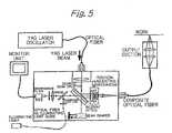
- a YAG laser oscillatoremits a machining laser beam which passes through an optical fiber to be guided to a laser combining dichroic beam splitter, from which the combined laser beam is reflected to get into incident optics, where it is processed to become passable through a composite optical fiber; thereafter, the laser beam travels through the composite optical fiber to be introduced into an output section, where it is focused to irradiate the work.
- Illuminating laser lightpasses through an illuminating light guiding optical fiber to be guided into the dichroic beam splitter, where it is added to the center of the machining laser; the combined laser beam enters the incident optics, where it is processed to become passable through the composite optical fiber; thereafter, the illuminating laser beam travels through the composite optical fiber to be introduced into the output section, where it is focused with the machining laser beam to irradiate the work.
- the image carrying laser beamis reflected from the work and travels in opposite direction to pass through the output section, the composite optical fiber, incident optics, beam splitter and finally through an interference filter to reach a monitor unit which displays the image of the illuminated lesion.
- the endoscope which is responsible for image observationis physically independent of the laser light transmitting optical fiber, so the image of the lesion needs to be checked either through the endoscope or by external x-ray monitoring.
- the doctorperforms treatment by applying laser light to the lesion while checking the position of the optical fiber with the aid of the image obtained from the endoscope or by x-ray monitoring.
- This techniquerequires that the surgeon perform laser application by first making visual check of the lesion and the optical fiber either through the endoscope or by x-ray monitoring and then, on the basis of the obtained image information, exercising his or her discretion in directing the tip of the optical fiber to the desired position with respect to the lesion.
- JP 9-216086A , JP 9-216087A and JP 2003-1465Awhich have a laser light transmitting section and an image transmitting section are all intended to be used under exposure to radiation or to transmit laser light of high output power. Since those composite optical fibers are fabricated from a stepped-index fiber whose core is made of pure quartz glass, it has been difficult to reduce the fiber diameter small enough to be suitable for use on endoscopes.
- the present inventionhas been accomplished under those circumstances and has as an object providing an endoscopic system whose diameter is small enough to allow for easy observation of the interior of the human body and which enables simultaneous observation of image with treatment by laser light irradiation.
- the present inventionprovides an endoscopic system according to claim 1.
- said large-diameter optical fiber and said image transmitting optical fiberare each an optical fiber which has GeO 2 doped quartz glass as the core and of which the core/cladding index difference ⁇ is 2-5%.
- said illuminating light transmitting unitcomprises a light source and a light guide that transmits the illuminating light emerging from said light source, at least the tip portion of said light guide being made integral with said image transmitting fiber in its longitudinal direction.
- the endoscopic system of the present inventionfurther includes a video monitor for displaying an image signal as it is picked up from said laser applying and image observing optical unit.
- Said laser applying and image observing optical unitpreferably includes a beam splitter that reflects the emission of laser light from a laser oscillator to be launched into said large-diameter optical fiber and which transmits the image traveling through said image transmitting optical fiber so that it is focused on said camera.
- the endoscopic system of the present inventionhas the advantage that by simply inserting a single fiberscope into the human body, the image of the lesion can be observed simultaneously with its treatment by laser light irradiation such that the surgeon can accurately apply the laser light to the lesion while examining a clear picture of the latter.
- the lesioncan be irradiated with the required intensity of laser light for the required time duration while checking them visually and, hence, superior therapeutic effect and high safety can be obtained.
- This inventionrelates to an endoscopic apparatus primarily intended for medical use, which is characterized by using a composite optical fiber as an integral assembly of an image transmitting image fiber for use in the finding and diagnosis of a lesion and a large-diameter, laser transmitting optical fiber for use in the treatment of the lesion and which has a sufficiently small diameter to allow for easy insertion into the human body.
- the conventional composite optical fibers described in JP 9-216086A , JP 9-216087A and JP 2003-1465A which have a laser light transmitting section and an image transmitting sectionare all intended to be used under exposure to radiation or to transmit laser light of high output power and they have been fabricated from a stepped-index fiber whose core is made of pure quartz glass having superior radiation resisting characteristics.
- the composite optical fiber to be used in the present inventionis characterized in that the large-diameter, laser light transmitting optical fiber and the image transmitting optical fiber are each preferably an optical fiber whose core is made of GeO 2 doped quartz glass and which has a core/cladding index difference ⁇ in the range of 2-5%. Using these design parameters, the present inventors could successfully reduce the diameter of the composite optical fiber to a comparable level to the image fiber employed in medical fiberscopes.
- a version of the image transmitting optical fiber employed in the conventional composite optical fiberhas a diameter of 1.7 mm with 15,000 pixels.
- this optical fiber serving as the pixel basishas a core/cladding index difference ⁇ of about 1% and a pixel-to-pixel spacing of about 10 ⁇ m has been necessary to perform appropriate image transmission.
- the diameter of the composite optical fiberincreases so much as to introduce difficulty in adopting it in an endoscopic fiberscope which in practical use is inserted into the human body.
- the image transmitting optical fiber to be used in the endoscopic system of the present inventionhas its core/cladding index difference ⁇ adjusted to lie within the range of 2-5%, preferably 3.5-4%, with the result that the core-to-core spacing can be reduced to as small as 3 ⁇ m; given the same number of pixels, the diameter of the image transmitting optical fiber can be reduced to 0.3 times the conventional value.
- Fig. 1is a cross-sectional view showing an example of the composite optical fiber that can advantageously be used in the present invention and which is generally indicated by numeral 1.
- numeral 2is a large-diameter fiber that is primarily intended for laser transmission and which consists of a core 3 made of GeO 2 doped quartz glass and a cladding 4 made of pure quartz glass.
- the diameter of the core 3is preferably in the range of 50-400 ⁇ m whereas the diameter of the cladding 4 preferably ranges from about 1.02 to about 1.3 times the core diameter, with the numerical aperture (NA) of the large-diameter fiber 2 typically ranging from about 0.2 to about 0.4.
- NAnumerical aperture
- the diameter of the core 3is less than 50 ⁇ m, the power of the laser light that can be transmitted is restricted, decreasing the likelihood to offer adequate efficacy in laser therapy. If the diameter of the core 3 is greater than 400 ⁇ m, it becomes difficult to achieve the desired reduction in the diameter of the composite optical fiber 1.
- the numerical aperture of the large-diameter fiber 2is within the range of 0.2 to 0.4, it can be materialized using quartz-based optical fibers and appropriate values can be chosen in accordance with a specific object of laser light irradiation, such as applying laser light with a maximum divergence of angle or irradiating a narrow area. It should be mentioned that there is no need to have a numerical aperture match between the large-diameter fiber 2 and the image transmitting optical fiber 5 to be described just below.
- the large-diameter fiber 2is surrounded by a large number of image transmitting fibers 5 that are bundled together.
- the image transmitting fibers 5are fused to form a monolithic sea-island structure in which a large number of cores 6 as islands are surrounded by a continuous phase of cladding 7 like a sea.
- the cores 6are made of GeO 2 doped quartz glass and the cladding 7 is made of pure quartz glass. Adjacent cores 6 are spaced apart by a distance of about 3 ⁇ m.
- the number of the image transmitting fibers 5 in a bundlerepresents the number of pixels and it preferably ranges from about 1,000 to 100,000.
- the spacing between cores 6is set from the value of the core/cladding index difference ⁇ and by adjusting the value of ⁇ to lie between 2 and 5%, preferably between 3.5 and 4%, the core-to-core spacing can be reduced to as small as 3 ⁇ m. If the number of pixels as defined above is less than 1,000, there is high likelihood for the failure to obtain a sharp image; if the number of pixels exceeds 100,000, it becomes difficult to manufacture a composite optical fiber of the desired small diameter.
- a core 3 of the large-diameter optical fiber 2is made of pure quartz glass or a GeO 2 doped quartz glass
- a cladding 4 of the large-diameter optical fiberis made of a fluorine or otherwise doped quartz glass having a lower reflective index than the core
- a core 6 of the image transmitting optical fiber 5is made of a GeO 2 doped quartz glass
- a cladding 7 of the image transmitting optical fiberis made of pure quartz glass or a fluorine or otherwise doped quartz glass having a lower reflective index than the pure quartz glass.
- the image transmitting optical fibercan be used for transmitting infrared radiation in addition to image observation using visible light.
- a rod of large-diameter fiber 2is placed at the center of a quartz tube serving as a quartz jacket layer 8 and then surrounded by optical fibers serving as image transmitting fibers 5 which are packed together to form a perform, which is then drawn down to a smaller-diameter fiber.
- the quartz jacket layer 8is preferably covered with a silicone resin, UV curable resin, polyimide resin, etc. to form a resin coating layer 9 in a thickness of from about 20 to about 100 ⁇ m.
- the outside diameter of the jacket layer on the composite optical fiber 1 of the above-described structurecan preferably be adjusted to range from about 0.3 mm to about 2 mm depending on the number of pixels to be presented.
- N0.9 ⁇ D / d 2
- the circle diameter Dis calculated from Eq. (1).
- the outside diameter of the jacket layeris about 1.1 times the circle diameter.
- Fig. 2shows an exemplary structure of the objective portion of a fiberscope employing the composite optical fiber.
- a sleeve 22is bonded and after polishing its surface, the tip is fitted with an objective lens unit 23.
- the objective lens unit 23is handled as the objective portion of an image fiber used in an ordinary fiberscope and it is surrounded by a lightguide fiber 24 over which illuminating light is transmitted to irradiate the area of interest, thereby forming the objective portion of a fiberscope.
- the lightguide fiber 24preferably uses a multi-component glass optical fiber, which may optionally be replaced by a quartz fiber or a plastic clad fiber.
- the multi-component glass optical fiberis available in very small fiber diameters ranging from 30 to 50 ⁇ m.
- the illuminating fiberhas to be inserted into a very small space, so the use of a particularly small-diameter fiber is preferred.
- the angle of viewing of fiberscopesis generally wide (60° - 120°) and the multi-component glass optical fiber is suitable for the purpose of illuminating such a wide range of area.
- the quartz-based optical fiberthe minimum fiber diameter and the angle of illumination that can be obtained are about 70 ⁇ m and 30 degrees, respectively, making it difficult for a fiberscope of high finder coverage to illuminate the entire area under observation.
- the entire objective portionis inserted into a protective tube 25 and bonded to its inner surfaces to form the tip at the objective end of the fiberscope.
- the protective tube 25may be a resin tube such as a fluoroplastic (e.g. PTFE, EFFE or PFA) tube, polyurethane tube or polyimide tube; alternatively, it may be a metal pipe such as a stainless steel pipe.
- Fig. 3shows an exemplary fiberscope using the composite optical fiber as it is generally indicated by 30.
- the principal components of the fiberscope 30are: the composite optical fiber 34; an objective lens unit 31 provided at the objective end 30A of the fiberscope; a terminal connector 36 provided at the eyepiece end 30B; a lightguide fiber 32 provided along the composite optical fiber 34; a protective tube 33 enclosing the above-mentioned components; and a branch 37 provided at the eyepiece end of the protective tube 33 to receive the lightguide fiber 32.
- the objective end 30A of the fiberscope 30is composed by inserting the objective lens unit 31 and the lightguide fiber 32 into the protective tube 33 and bonding them in position.
- a sleeve 35is bonded to the objective end of the composite optical fiber 34 and its end face is polished.
- a terminal connector 36is bonded to the eyepiece end 30B of the fiberscope 30, with its fiber end being polished.
- the lightguide fiber 32diverges at the branch 37 and fitted with a terminator 38 for establishing connection to an illuminating device.
- Fig. 4shows an example of an endoscopic observation system according to the present invention which is generally indicated by 40.
- the endoscopic observation system 40comprises: the fiberscope 30 having the composite optical fiber 34 and the lightguide fiber 32; a laser applying and image observing optical assembly 42 connected to the eyepiece portion of the fiberscope 30; a laser oscillator 10 that transmits laser to the laser applying and image observing optical assembly 42 via an optical fiber 41; an illuminator 51 that illuminates the objective end of the fiberscope 30 with light as it is passed through the lightguide fiber 32; and a video monitor 49 which displays an image signal as it is picked up from the laser applying and image observing optical assembly 42.
- the laser applying and image observing optical assembly 42is so adapted that laser light is launched into the large-diameter optical fiber in the composite optical fiber 34 whereas the image carrying laser light traveling in opposite direction through the image transmitting optical fiber forms a focused image on a CCD camera 48 such that it is observable by the operator.
- the terminal connector 36 at the eyepiece end of the fiberscope 30is fitted on an adapter 52 of the laser applying and image observing optical assembly 42.
- the lightguide fiber 32is connected at the terminator 38 to the illuminator 51.
- the optical fiber 41 connecting the laser oscillator 10 to the laser applying and image observing optical assembly 42may be of the same type as the large-diameter optical fiber in the composite optical fiber 34 but this is not the sole case of the present invention. If the laser oscillator 10 is small in size, it may be directly connected to the laser applying and image observing optical assembly 42; alternatively, a mirror, lenses and other optional optics may be combined for transmitting laser light.
- the laser applying and image observing optical assembly 42comprises: the CCD camera 48 fitted with a camera lens 47; a beam splitter 44 which reflects the laser light from the laser oscillator 10 to be launched into the large-diameter fiber and which also transmits the image carrying laser light traveling in opposite direction through the image transmitting optical fiber to form a focused image on the CCD camera 48; an optical unit composed of condenser lenses 43a and 43b and a relay lens subunit 45; and an interference filter 46 for blocking the laser light.
- the image carrying laser light traveling through the image transmitting optical fiber in the composite optical fiber 34passes through the condenser lens 43a, the visible light transmitting beam splitter 44, the relay lens subunit 45 and the laser light blocking interference filter 46; it then passes through the camera lens 47 to form a focused image on the CCD camera 48.
- An image signal outputted from the CCD camera 48is displayed on the video monitor 49. The operator can manipulate the fiberscope 30 while observing the image being displayed on the video monitor 49.
- Laser light emitted from the laser oscillator 10travels through the optical fiber 41 to be transmitted to the laser applying and image observing optical assembly 42, from which it passes through the condenser lens 43b, is reflected by the beam splitter 44 and then passes through the condenser lens 43a to be launched into the core of the large-diameter optical fiber in the composite optical fiber 34; the laser light emerges from the objective end 30A of the fiberscope 30 to irradiate the area under observation.
- the laser oscillator 10can choose the most suitable laser light depending on the severity of the lesion and the regimen of treatment. For example, a variety of lasers having wavelengths ranging from the visible to the near infrared region may be employed and they include a dye laser, an argon ion laser, a semiconductor laser, a Nd:YAG laser, a Ho:YAG laser, etc.
- the large-diameter core of the laser light transmitting portionmay be formed of pure quartz glass, with the cladding being formed of fluorine-doped quartz glass.
- an excimer lasersuch as XeCl, KrF or ArF can also be used as a light source.
- Laser light emitted from the laser oscillator 10travels through the optical fiber 41 and enters the laser applying and image observing optical assembly 42, in which it passes through the condenser lens 43b, is reflected by the beam splitter 44 to get into the condenser lens 43a as an incident optical element, where it is processed to become passable through the composite optical fiber 34; thereafter, the laser light travels through the composite optical fiber 34 to be introduced into the objective end 30A, where it is focused by the objective lens unit 23 or 31 to irradiate the lesion.
- Illuminating laser light from the illuminator 51passes through the lightguide fiber 32 to be introduced into the objective end 30A, where it is focused with the surgical laser beam to irradiate the lesion.
- the image carrying laser lightis reflected from the lesion and travels in opposite direction to pass through the objective end 30A, composite optical fiber 34, condenser lens 43a, beam splitter 44, relay lens subunit 45, interference filter 46, and finally through the camera lens 47 to form a focused image on the CCD camera 48 which outputs an image signal that reaches the video monitor 49 which displays the image of the illuminated lesion on the screen.
- the Nd:YAG laser lightis directed at the occlusion to evaporate and cauterize it. Also possible are laser vascular anastomosis and coronary artery bypass surgery.
- the fiberscope in the endoscopic system of the inventionis inserted into the urinary tract and with the position of the stone being checked on the display screen, Ho:YAG laser light or the like is precisely directed at the stone to crush it.
- the current practice of fundus photocoagulationinvolves transmitting argon ion laser light over an optical fiber under endoscopic observation. If the endoscopic system of the present invention is used, the fiberscope needs to be inserted only at one site and yet one can perform coaxial and accurate laser irradiation to perform surgery.
- a material having tumor affinity and photosensitivitysay, a hematoporphyrin derivative (HpD) is administered.
- Tumor cells in which HpD has accumulatedare irradiated with exciting laser light as from an excimer laser of extremely low energy, whereupon HpD emits fluorescence.
- the resulting fluorescence spectrum peculiar to HpDis detected in the image transmitting section and observed with a CCD camera as a two-dimensional image.
- the fluorescence spectrummay be connected to a spectroscope and analyzed for diagnostic purposes.
- the laser light sourcemay be switched over to a near infrared laser light source such as Nd:YAG laser and the lesion that has been found to be a tumor by diagnosis is irradiated with the laser light so that it is evaporated and cauterized for treatment.
- a near infrared laser light sourcesuch as Nd:YAG laser
- cancer cellsmay be diagnosed and treated by laser light irradiation using photosensitive materials.
Landscapes
- Health & Medical Sciences (AREA)
- Physics & Mathematics (AREA)
- Life Sciences & Earth Sciences (AREA)
- Surgery (AREA)
- Optics & Photonics (AREA)
- Nuclear Medicine, Radiotherapy & Molecular Imaging (AREA)
- Public Health (AREA)
- Molecular Biology (AREA)
- Veterinary Medicine (AREA)
- General Health & Medical Sciences (AREA)
- Animal Behavior & Ethology (AREA)
- Engineering & Computer Science (AREA)
- Biomedical Technology (AREA)
- Heart & Thoracic Surgery (AREA)
- Medical Informatics (AREA)
- Pathology (AREA)
- Radiology & Medical Imaging (AREA)
- Biophysics (AREA)
- General Physics & Mathematics (AREA)
- Astronomy & Astrophysics (AREA)
- Electromagnetism (AREA)
- Otolaryngology (AREA)
- Oral & Maxillofacial Surgery (AREA)
- Gynecology & Obstetrics (AREA)
- Endoscopes (AREA)
- Laser Surgery Devices (AREA)
Description
- This invention relates to an endoscopic apparatus primarily intended for medical use. More particularly, the invention relates to an endoscopic apparatus using an extremely fine composite optical fiber as an integral assembly of an image transmitting optical fiber for use in the finding and diagnosis of a lesion and a large-diameter, laser transmitting optical fiber for use in the treatment of the lesion.
- Heretofore, endoscopes using a fused monolithic image fiber or an optical fiber such as an image bundle have been commercialized in various types. Transmitting laser light to the lesion over the optical fiber is also a commercialized technique in laser therapy.
- Conventionally, the endoscope and the laser transmitting optical fiber are physically independent of each other and must be inserted into the human body either through separate holes or via the lumens of catheter tubes.
- In a non-medical field and for the purpose of cutting and welding metals, laser machining methods and systems have been proposed and they employ a composite optical fiber that consists of a large-diameter, machining laser light transmitting fiber surrounded by a large number of image transmitting fibers that are bundled together to form an integral assembly with the central fiber (see, for example,
JP 9-216086A JP 9-216087A JP 2003-1465A - The laser machining method or system proposed by
JP 2003-1465A Fig. 5 ; a YAG laser oscillator emits a machining laser beam which passes through an optical fiber to be guided to a laser combining dichroic beam splitter, from which the combined laser beam is reflected to get into incident optics, where it is processed to become passable through a composite optical fiber; thereafter, the laser beam travels through the composite optical fiber to be introduced into an output section, where it is focused to irradiate the work. - Illuminating laser light, on the other hand, passes through an illuminating light guiding optical fiber to be guided into the dichroic beam splitter, where it is added to the center of the machining laser; the combined laser beam enters the incident optics, where it is processed to become passable through the composite optical fiber; thereafter, the illuminating laser beam travels through the composite optical fiber to be introduced into the output section, where it is focused with the machining laser beam to irradiate the work.
- The image carrying laser beam is reflected from the work and travels in opposite direction to pass through the output section, the composite optical fiber, incident optics, beam splitter and finally through an interference filter to reach a monitor unit which displays the image of the illuminated lesion.
- In all conventional laser therapeutic systems, the endoscope which is responsible for image observation is physically independent of the laser light transmitting optical fiber, so the image of the lesion needs to be checked either through the endoscope or by external x-ray monitoring. With the laser light transmitting optical fiber inserted into the human body until it comes close enough to the lesion, the doctor performs treatment by applying laser light to the lesion while checking the position of the optical fiber with the aid of the image obtained from the endoscope or by x-ray monitoring.
- This technique requires that the surgeon perform laser application by first making visual check of the lesion and the optical fiber either through the endoscope or by x-ray monitoring and then, on the basis of the obtained image information, exercising his or her discretion in directing the tip of the optical fiber to the desired position with respect to the lesion.
- However, directing the tip of the laser illuminating optical fiber to the desired position with respect to the lesion largely depends on the skill and discretion of the operator and so does the accuracy with which the applied laser light can fall on the target position of the lesion. What is more, unwanted exposure to x-rays from the outside can cause not only a safety problem but also inconsistency in the efficacy of laser therapy.
- The conventional composite optical fibers described in
JP 9-216086A JP 9-216087A JP 2003-1465A - The present invention has been accomplished under those circumstances and has as an object providing an endoscopic system whose diameter is small enough to allow for easy observation of the interior of the human body and which enables simultaneous observation of image with treatment by laser light irradiation.
- To attain the stated object, the present invention provides an endoscopic system according to claim 1.
- In the endoscopic system of the present invention, said large-diameter optical fiber and said image transmitting optical fiber are each an optical fiber which has GeO2 doped quartz glass as the core and of which the core/cladding index difference Δ is 2-5%.
- Further, said illuminating light transmitting unit comprises a light source and a light guide that transmits the illuminating light emerging from said light source, at least the tip portion of said light guide being made integral with said image transmitting fiber in its longitudinal direction.
- In another preferred embodiment, the endoscopic system of the present invention further includes a video monitor for displaying an image signal as it is picked up from said laser applying and image observing optical unit.
- Said laser applying and image observing optical unit preferably includes a beam splitter that reflects the emission of laser light from a laser oscillator to be launched into said large-diameter optical fiber and which transmits the image traveling through said image transmitting optical fiber so that it is focused on said camera.
- The endoscopic system of the present invention has the advantage that by simply inserting a single fiberscope into the human body, the image of the lesion can be observed simultaneously with its treatment by laser light irradiation such that the surgeon can accurately apply the laser light to the lesion while examining a clear picture of the latter. As a matter of course, there is no need to fear for the risk of exposure to x-rays through external irradiation.
- In addition, erroneous irradiation can be prevented since continuous image observation is possible not only during the application of laser light but also after that as well.
- As a further advantage, the lesion can be irradiated with the required intensity of laser light for the required time duration while checking them visually and, hence, superior therapeutic effect and high safety can be obtained.
Fig. 1 is a cross-sectional view showing an example of the composite optical fiber for use in the endoscopic system of the present invention;Fig. 2 is a longitudinal section of an example of the objective portion of a fiberscope which is to be used in the endoscopic system of the present invention;Fig. 3 is a longitudinal section of an example of the fiberscope which is to be used in the endoscopic system of the present invention;Fig. 4 shows diagrammatically an example of the endoscopic system of the present invention; andFig. 5 shows an exemplary laser machining system which employs the conventional composite optical fiber.- This invention relates to an endoscopic apparatus primarily intended for medical use, which is characterized by using a composite optical fiber as an integral assembly of an image transmitting image fiber for use in the finding and diagnosis of a lesion and a large-diameter, laser transmitting optical fiber for use in the treatment of the lesion and which has a sufficiently small diameter to allow for easy insertion into the human body.
- The conventional composite optical fibers described in
JP 9-216086A JP 9-216087A JP 2003-1465A - A version of the image transmitting optical fiber employed in the conventional composite optical fiber has a diameter of 1.7 mm with 15,000 pixels. When in an uncoated state, this optical fiber serving as the pixel basis has a core/cladding index difference Δ of about 1% and a pixel-to-pixel spacing of about 10 µm has been necessary to perform appropriate image transmission. Hence, if one uses this conventional image transmitting optical fiber to form an image transmitting section having a large number of pixels, the diameter of the composite optical fiber increases so much as to introduce difficulty in adopting it in an endoscopic fiberscope which in practical use is inserted into the human body. On the other hand, the image transmitting optical fiber to be used in the endoscopic system of the present invention has its core/cladding index difference Δ adjusted to lie within the range of 2-5%, preferably 3.5-4%, with the result that the core-to-core spacing can be reduced to as small as 3 µm; given the same number of pixels, the diameter of the image transmitting optical fiber can be reduced to 0.3 times the conventional value.
Fig. 1 is a cross-sectional view showing an example of the composite optical fiber that can advantageously be used in the present invention and which is generally indicated by numeral 1. Indicated by numeral 2 is a large-diameter fiber that is primarily intended for laser transmission and which consists of acore 3 made of GeO2 doped quartz glass and a cladding 4 made of pure quartz glass. The diameter of thecore 3 is preferably in the range of 50-400 µm whereas the diameter of thecladding 4 preferably ranges from about 1.02 to about 1.3 times the core diameter, with the numerical aperture (NA) of the large-diameter fiber 2 typically ranging from about 0.2 to about 0.4.- If the diameter of the
core 3 is less than 50 µm, the power of the laser light that can be transmitted is restricted, decreasing the likelihood to offer adequate efficacy in laser therapy. If the diameter of thecore 3 is greater than 400 µm, it becomes difficult to achieve the desired reduction in the diameter of the composite optical fiber 1. - If the numerical aperture of the large-diameter fiber 2 is within the range of 0.2 to 0.4, it can be materialized using quartz-based optical fibers and appropriate values can be chosen in accordance with a specific object of laser light irradiation, such as applying laser light with a maximum divergence of angle or irradiating a narrow area. It should be mentioned that there is no need to have a numerical aperture match between the large-diameter fiber 2 and the image transmitting optical fiber 5 to be described just below.
- The large-diameter fiber 2 is surrounded by a large number of image transmitting fibers 5 that are bundled together. The image transmitting fibers 5 are fused to form a monolithic sea-island structure in which a large number of cores 6 as islands are surrounded by a continuous phase of cladding 7 like a sea. The cores 6 are made of GeO2 doped quartz glass and the
cladding 7 is made of pure quartz glass. Adjacent cores 6 are spaced apart by a distance of about 3 µm. The number of the image transmitting fibers 5 in a bundle represents the number of pixels and it preferably ranges from about 1,000 to 100,000. - As already mentioned, the spacing between cores 6 is set from the value of the core/cladding index difference Δ and by adjusting the value of Δ to lie between 2 and 5%, preferably between 3.5 and 4%, the core-to-core spacing can be reduced to as small as 3 µm. If the number of pixels as defined above is less than 1,000, there is high likelihood for the failure to obtain a sharp image; if the number of pixels exceeds 100,000, it becomes difficult to manufacture a composite optical fiber of the desired small diameter.
- As an example of a composite optical fiber not forming part of the invention, a
core 3 of the large-diameter optical fiber 2 is made of pure quartz glass or a GeO2 doped quartz glass, acladding 4 of the large-diameter optical fiber is made of a fluorine or otherwise doped quartz glass having a lower reflective index than the core, a core 6 of the image transmitting optical fiber 5 is made of a GeO2 doped quartz glass, and acladding 7 of the image transmitting optical fiber is made of pure quartz glass or a fluorine or otherwise doped quartz glass having a lower reflective index than the pure quartz glass. - The image transmitting optical fiber can be used for transmitting infrared radiation in addition to image observation using visible light.
- To make the composite optical fiber 1 in the embodiment under consideration, a rod of large-diameter fiber 2 is placed at the center of a quartz tube serving as a quartz jacket layer 8 and then surrounded by optical fibers serving as image transmitting fibers 5 which are packed together to form a perform, which is then drawn down to a smaller-diameter fiber. In this drawing step, the quartz jacket layer 8 is preferably covered with a silicone resin, UV curable resin, polyimide resin, etc. to form a
resin coating layer 9 in a thickness of from about 20 to about 100 µm. By adjusting the thickness of theresin coating layer 9 to be within the stated range, a composite optical fiber having the intended small diameter can be fabricated and yet it meets the requirement for guaranteed strength. - The outside diameter of the jacket layer on the composite optical fiber 1 of the above-described structure can preferably be adjusted to range from about 0.3 mm to about 2 mm depending on the number of pixels to be presented.
- If the core-to-core spacing is written as d and the circle diameter as D, the number of pixels N is determined by the following equation:

- After determining d from the index difference Δ and given the required number of pixels N, the circle diameter D is calculated from Eq. (1). The outside diameter of the jacket layer is about 1.1 times the circle diameter.
Fig. 2 shows an exemplary structure of the objective portion of a fiberscope employing the composite optical fiber. To the tip of the compositeoptical fiber 21, a sleeve 22 is bonded and after polishing its surface, the tip is fitted with anobjective lens unit 23. Theobjective lens unit 23 is handled as the objective portion of an image fiber used in an ordinary fiberscope and it is surrounded by alightguide fiber 24 over which illuminating light is transmitted to irradiate the area of interest, thereby forming the objective portion of a fiberscope. Thelightguide fiber 24 preferably uses a multi-component glass optical fiber, which may optionally be replaced by a quartz fiber or a plastic clad fiber.- The multi-component glass optical fiber is available in very small fiber diameters ranging from 30 to 50 µm. In the case of fine fiberscopes, the illuminating fiber has to be inserted into a very small space, so the use of a particularly small-diameter fiber is preferred. The angle of viewing of fiberscopes is generally wide (60° - 120°) and the multi-component glass optical fiber is suitable for the purpose of illuminating such a wide range of area. With the quartz-based optical fiber, the minimum fiber diameter and the angle of illumination that can be obtained are about 70 µm and 30 degrees, respectively, making it difficult for a fiberscope of high finder coverage to illuminate the entire area under observation.
- The entire objective portion is inserted into a
protective tube 25 and bonded to its inner surfaces to form the tip at the objective end of the fiberscope. Theprotective tube 25 may be a resin tube such as a fluoroplastic (e.g. PTFE, EFFE or PFA) tube, polyurethane tube or polyimide tube; alternatively, it may be a metal pipe such as a stainless steel pipe. Fig. 3 shows an exemplary fiberscope using the composite optical fiber as it is generally indicated by 30. The principal components of thefiberscope 30 are: the compositeoptical fiber 34; anobjective lens unit 31 provided at theobjective end 30A of the fiberscope; aterminal connector 36 provided at theeyepiece end 30B; alightguide fiber 32 provided along the compositeoptical fiber 34; aprotective tube 33 enclosing the above-mentioned components; and abranch 37 provided at the eyepiece end of theprotective tube 33 to receive thelightguide fiber 32.- The
objective end 30A of thefiberscope 30 is composed by inserting theobjective lens unit 31 and thelightguide fiber 32 into theprotective tube 33 and bonding them in position. Asleeve 35 is bonded to the objective end of the compositeoptical fiber 34 and its end face is polished. Aterminal connector 36 is bonded to theeyepiece end 30B of thefiberscope 30, with its fiber end being polished. Thelightguide fiber 32 diverges at thebranch 37 and fitted with aterminator 38 for establishing connection to an illuminating device. Fig. 4 shows an example of an endoscopic observation system according to the present invention which is generally indicated by 40. Theendoscopic observation system 40 comprises: thefiberscope 30 having the compositeoptical fiber 34 and thelightguide fiber 32; a laser applying and image observingoptical assembly 42 connected to the eyepiece portion of thefiberscope 30; alaser oscillator 10 that transmits laser to the laser applying and image observingoptical assembly 42 via anoptical fiber 41; anilluminator 51 that illuminates the objective end of thefiberscope 30 with light as it is passed through thelightguide fiber 32; and avideo monitor 49 which displays an image signal as it is picked up from the laser applying and image observingoptical assembly 42. The laser applying and image observingoptical assembly 42 is so adapted that laser light is launched into the large-diameter optical fiber in the compositeoptical fiber 34 whereas the image carrying laser light traveling in opposite direction through the image transmitting optical fiber forms a focused image on aCCD camera 48 such that it is observable by the operator.- The
terminal connector 36 at the eyepiece end of thefiberscope 30 is fitted on anadapter 52 of the laser applying and image observingoptical assembly 42. Thelightguide fiber 32 is connected at theterminator 38 to theilluminator 51. Theoptical fiber 41 connecting thelaser oscillator 10 to the laser applying and image observingoptical assembly 42 may be of the same type as the large-diameter optical fiber in the compositeoptical fiber 34 but this is not the sole case of the present invention. If thelaser oscillator 10 is small in size, it may be directly connected to the laser applying and image observingoptical assembly 42; alternatively, a mirror, lenses and other optional optics may be combined for transmitting laser light. - The laser applying and image observing
optical assembly 42 comprises: theCCD camera 48 fitted with acamera lens 47; abeam splitter 44 which reflects the laser light from thelaser oscillator 10 to be launched into the large-diameter fiber and which also transmits the image carrying laser light traveling in opposite direction through the image transmitting optical fiber to form a focused image on theCCD camera 48; an optical unit composed ofcondenser lenses relay lens subunit 45; and aninterference filter 46 for blocking the laser light. - The image carrying laser light traveling through the image transmitting optical fiber in the composite
optical fiber 34 passes through thecondenser lens 43a, the visible lighttransmitting beam splitter 44, therelay lens subunit 45 and the laser light blockinginterference filter 46; it then passes through thecamera lens 47 to form a focused image on theCCD camera 48. An image signal outputted from theCCD camera 48 is displayed on thevideo monitor 49. The operator can manipulate thefiberscope 30 while observing the image being displayed on thevideo monitor 49. - Laser light emitted from the
laser oscillator 10 travels through theoptical fiber 41 to be transmitted to the laser applying and image observingoptical assembly 42, from which it passes through thecondenser lens 43b, is reflected by thebeam splitter 44 and then passes through thecondenser lens 43a to be launched into the core of the large-diameter optical fiber in the compositeoptical fiber 34; the laser light emerges from theobjective end 30A of thefiberscope 30 to irradiate the area under observation. - The
laser oscillator 10 can choose the most suitable laser light depending on the severity of the lesion and the regimen of treatment. For example, a variety of lasers having wavelengths ranging from the visible to the near infrared region may be employed and they include a dye laser, an argon ion laser, a semiconductor laser, a Nd:YAG laser, a Ho:YAG laser, etc. - In the composite optical fiber according to the present invention, the large-diameter core of the laser light transmitting portion may be formed of pure quartz glass, with the cladding being formed of fluorine-doped quartz glass. With this design, an excimer laser such as XeCl, KrF or ArF can also be used as a light source.
- Laser light emitted from the
laser oscillator 10 travels through theoptical fiber 41 and enters the laser applying and image observingoptical assembly 42, in which it passes through thecondenser lens 43b, is reflected by thebeam splitter 44 to get into thecondenser lens 43a as an incident optical element, where it is processed to become passable through the compositeoptical fiber 34; thereafter, the laser light travels through the compositeoptical fiber 34 to be introduced into theobjective end 30A, where it is focused by theobjective lens unit - Illuminating laser light from the illuminator 51 passes through the
lightguide fiber 32 to be introduced into theobjective end 30A, where it is focused with the surgical laser beam to irradiate the lesion. - The image carrying laser light is reflected from the lesion and travels in opposite direction to pass through the
objective end 30A, compositeoptical fiber 34,condenser lens 43a,beam splitter 44,relay lens subunit 45,interference filter 46, and finally through thecamera lens 47 to form a focused image on theCCD camera 48 which outputs an image signal that reaches the video monitor 49 which displays the image of the illuminated lesion on the screen. - The following are typical examples of endoscopic laser therapy that may be practiced by using the endoscopic system of the present invention.
- As a thrombus in an artery is observed, the Nd:YAG laser light is directed at the occlusion to evaporate and cauterize it. Also possible are laser vascular anastomosis and coronary artery bypass surgery.
- The fiberscope in the endoscopic system of the invention is inserted into the urinary tract and with the position of the stone being checked on the display screen, Ho:YAG laser light or the like is precisely directed at the stone to crush it.
- The current practice of fundus photocoagulation involves transmitting argon ion laser light over an optical fiber under endoscopic observation. If the endoscopic system of the present invention is used, the fiberscope needs to be inserted only at one site and yet one can perform coaxial and accurate laser irradiation to perform surgery.
- In the treatment of coronary arteriosclerosis or other disease, a material having tumor affinity and photosensitivity, say, a hematoporphyrin derivative (HpD) is administered. Tumor cells in which HpD has accumulated are irradiated with exciting laser light as from an excimer laser of extremely low energy, whereupon HpD emits fluorescence. The resulting fluorescence spectrum peculiar to HpD is detected in the image transmitting section and observed with a CCD camera as a two-dimensional image. Alternatively, the fluorescence spectrum may be connected to a spectroscope and analyzed for diagnostic purposes.
- If desired, the laser light source may be switched over to a near infrared laser light source such as Nd:YAG laser and the lesion that has been found to be a tumor by diagnosis is irradiated with the laser light so that it is evaporated and cauterized for treatment.
- Similarly, cancer cells may be diagnosed and treated by laser light irradiation using photosensitive materials.

Claims (4)
- An endoscopic system comprising a composite optical fiber (1, 34) that consists of a large-diameter, laser light transmitting optical fiber (2) surrounded by a large number of image transmitting optical fibers (5) that are bundled together to form an integral assembly with the central fiber, a laser applying and image observing optical unit (42) that is connected to the eyepiece portion (30B) of said composite optical fiber (1, 34) such that it launches laser light into said large-diameter optical fiber (2) and that the image being transmitted through said image transmitting optical fibers (5) is focused on a camera (48) to become observable, and an illuminating light transmitting unit (51, 38, 32) that transmits illuminating light to the tip of the objective portion (30A) of said composite optical fiber (1,34) for irradiation purposes,characterized in that
a core (3) of the large-diameter optical fiber (2) is made of GeO2 doped quartz glass, a cladding (4) of the large-diameter optical fiber (2) is made of pure quartz glass, and its core/cladding index difference is adjusted to lie within the range of 2 to 5 %;
a core (6) of the image transmitting optical fiber (5) is made of GeO2 doped quartz glass, a cladding (7) of the image transmitting optical fiber is made of pure quartz glass, and its core/cladding index difference is adjusted to lie within the range of 2 to 5 %; and
the illuminating light transmitting unit comprises a light source (51) and a lightguide fiber (32) that is provided along the composite optical fiber (1) and transmits the illuminating light emerging from said light source (51), at least the tip portion of said light guide being made integral with the image transmitting fiber in its longitudinal direction. - The endoscopic system according to claim 1, which further includes a video monitor (49) for displaying an image signal as it is picked up from said laser applying and image observing optical unit.
- The endoscopic system according to any one of claims 1 to 3, wherein said laser applying and image observing optical unit includes a beam splitter (44) that reflects the emission of laser light from a laser oscillator (10) to be launched into said large-diameter optical fiber and which transmits the image traveling through said image transmitting optical fiber so that it is focused on said camera.
- The endoscopic system according to claim 1, wherein the image transmitting fiber is used for transmitting infrared radiation.
Applications Claiming Priority (4)
| Application Number | Priority Date | Filing Date | Title |
|---|---|---|---|
| JP2004047579 | 2004-02-24 | ||
| JP2004047579AJP4521528B2 (en) | 2004-02-24 | 2004-02-24 | Endoscope system using ultrafine composite optical fiber |
| JP2004242099AJP2006058740A (en) | 2004-08-23 | 2004-08-23 | Composite optical fiber |
| JP2004242099 | 2004-08-23 |
Publications (2)
| Publication Number | Publication Date |
|---|---|
| EP1568333A1 EP1568333A1 (en) | 2005-08-31 |
| EP1568333B1true EP1568333B1 (en) | 2008-04-16 |
Family
ID=34752148
Family Applications (1)
| Application Number | Title | Priority Date | Filing Date |
|---|---|---|---|
| EP05003877AExpired - LifetimeEP1568333B1 (en) | 2004-02-24 | 2005-02-23 | Endoscopic system using an extremely fine composite optical fiber |
Country Status (3)
| Country | Link |
|---|---|
| US (1) | US7582057B2 (en) |
| EP (1) | EP1568333B1 (en) |
| DE (1) | DE602005006030T2 (en) |
Families Citing this family (49)
| Publication number | Priority date | Publication date | Assignee | Title |
|---|---|---|---|---|
| US7922654B2 (en) | 2004-08-09 | 2011-04-12 | Boston Scientific Scimed, Inc. | Fiber optic imaging catheter |
| ES2552252T3 (en)* | 2004-03-23 | 2015-11-26 | Boston Scientific Limited | Live View System |
| US11819192B2 (en) | 2004-03-23 | 2023-11-21 | Boston Scientific Scimed, Inc. | In-vivo visualization system |
| US7556414B2 (en) | 2005-10-07 | 2009-07-07 | Karl Storz Endovision, Inc. | Endoscopic light source safety and control system with optical sensor |
| US7563010B2 (en)* | 2005-10-07 | 2009-07-21 | Karl Storz Endovision, Inc. | Endoscopic light source safety and control system with optical sensor |
| JP4409499B2 (en)* | 2005-10-25 | 2010-02-03 | 国立大学法人浜松医科大学 | Thrombolysis device |
| US20070146480A1 (en)* | 2005-12-22 | 2007-06-28 | Judge John J Jr | Apparatus and method for inspecting areas surrounding nuclear boiling water reactor core and annulus regions |
| US20080255460A1 (en)* | 2007-04-13 | 2008-10-16 | Ethicon Endo-Surgery, Inc. | Nanoparticle tissue based identification and illumination |
| CA2721846C (en) | 2008-04-18 | 2021-01-26 | Pharmacophotonics, Inc. | Renal function analysis method and apparatus |
| US8591865B2 (en) | 2008-04-18 | 2013-11-26 | Pharmacophotonics, Inc. | Renal function analysis method and apparatus |
| JP5520540B2 (en)* | 2008-08-19 | 2014-06-11 | 株式会社フジクラ | Endoscope system |
| JP5305946B2 (en)* | 2009-01-27 | 2013-10-02 | 富士フイルム株式会社 | Light guide, light source device and endoscope system |
| DE102009040093A1 (en) | 2009-09-04 | 2011-04-07 | Olympus Winter & Ibe Gmbh | Medical light for backlight and stimulation light |
| EP2522269B1 (en)* | 2010-01-08 | 2016-07-27 | Konica Minolta Advanced Layers, Inc. | Probe |
| US20120265010A1 (en)* | 2011-04-12 | 2012-10-18 | Endo Optiks, Inc. | Laser Video Endoscope |
| US20160095507A1 (en)* | 2010-05-13 | 2016-04-07 | Beaver-Visitec International, Inc. | Laser video endoscope |
| US10226167B2 (en)* | 2010-05-13 | 2019-03-12 | Beaver-Visitec International, Inc. | Laser video endoscope |
| KR101544683B1 (en)* | 2010-06-08 | 2015-08-13 | 가부시키가이샤 구라레 | Composite optical fiber and method of manufacturing the same |
| WO2012164838A1 (en) | 2011-05-31 | 2012-12-06 | コニカミノルタアドバンストレイヤー株式会社 | Optical fiber assembly, optical probe, and method for manufacturing optical fiber assembly |
| JP5380581B2 (en)* | 2012-06-08 | 2014-01-08 | 株式会社フジクラ | Lighting structure and endoscope |
| JP5771227B2 (en)* | 2013-02-05 | 2015-08-26 | 株式会社フジクラ | Method for manufacturing base material for multi-core fiber, and method for manufacturing multi-core fiber |
| KR101480016B1 (en)* | 2013-08-23 | 2015-01-07 | 주식회사 현주인테크 | Portable endoscope system |
| KR101524723B1 (en)* | 2013-10-31 | 2015-06-02 | 주식회사 옵티메드 | Inspection system capable of laser treatment |
| US9877784B2 (en)* | 2014-03-28 | 2018-01-30 | Electronics And Telecommunications Research Institute | Light transmitting cable and laser system including the same |
| CN103989459B (en)* | 2014-05-20 | 2021-05-18 | 曾堃 | Optical observation device and endoscope for identifying malignant tumor formation process |
| US12419508B2 (en) | 2014-05-20 | 2025-09-23 | Kun Zeng | Optical observation equipment and method for identifying forming process of malignant tumor and endoscope |
| CN104161590A (en)* | 2014-09-10 | 2014-11-26 | 山东省药物研究院 | Multi-wavelength laser endoscope device |
| US20180209405A1 (en)* | 2015-08-13 | 2018-07-26 | Vindum Engineering Inc. | Improved pulse-free metering pump and methods relating thereto |
| CN108463154B (en)* | 2016-01-13 | 2021-02-26 | 奥林巴斯株式会社 | Endoscope with a detachable handle |
| CN107957401A (en)* | 2017-12-18 | 2018-04-24 | 中国科学院西安光学精密机械研究所 | Hyperspectral microimager for interventional tumor diagnosis |
| SG11202107233VA (en) | 2019-01-09 | 2021-07-29 | Vena Medical Holdings Corp | Cerebrovascular pathology viewing and treatment apparatus |
| US11076933B2 (en) | 2019-04-19 | 2021-08-03 | Elt Sight, Inc. | Authentication systems and methods for an excimer laser system |
| US11234866B2 (en) | 2019-04-19 | 2022-02-01 | Elios Vision, Inc. | Personalization of excimer laser fibers |
| US11103382B2 (en) | 2019-04-19 | 2021-08-31 | Elt Sight, Inc. | Systems and methods for preforming an intraocular procedure for treating an eye condition |
| US11389239B2 (en) | 2019-04-19 | 2022-07-19 | Elios Vision, Inc. | Enhanced fiber probes for ELT |
| US11076992B2 (en) | 2019-04-19 | 2021-08-03 | Elt Sight, Inc. | Methods of transverse placement in ELT |
| US11672475B2 (en) | 2019-04-19 | 2023-06-13 | Elios Vision, Inc. | Combination treatment using ELT |
| JP2022543429A (en)* | 2019-08-05 | 2022-10-12 | ジャイラス エーシーエムアイ インク ディー/ビー/エー オリンパス サージカル テクノロジーズ アメリカ | fiber optic assembly |
| CN110432855A (en)* | 2019-09-10 | 2019-11-12 | 广东实联医疗器械有限公司 | A kind of integrated medical endoscopic system |
| CN111474625B (en)* | 2020-03-02 | 2021-11-09 | 华中科技大学 | Multiband transmission optical fiber and preparation method thereof |
| CN111399110A (en)* | 2020-03-02 | 2020-07-10 | 华中科技大学 | Multifunctional optical fiber and preparation method thereof |
| CN113440090B (en)* | 2020-03-24 | 2023-07-11 | 北京华信佳音医疗科技发展有限责任公司 | Split medical endoscope |
| US20240366071A1 (en)* | 2021-08-10 | 2024-11-07 | Hang An Medtech (Hangzhou) Co., Ltd. | Scanning fiber endoscope probes and scanning fiber endoscopes |
| CN114403794A (en)* | 2022-02-14 | 2022-04-29 | 清华大学 | Angioscope and method based on optical fiber imaging |
| CN115251811B (en)* | 2022-08-15 | 2024-06-25 | 中南大学 | Large-depth photoacoustic multi-mode flexible endoscopic imaging probe based on micro stepping motor |
| US12409069B2 (en) | 2022-08-30 | 2025-09-09 | Elios Vision, Inc. | Systems and methods for a combined excimer laser and phacoemulsification unit |
| US11877951B1 (en) | 2022-08-30 | 2024-01-23 | Elios Vision, Inc. | Systems and methods for applying excimer laser energy with transverse placement in the eye |
| US11903876B1 (en) | 2022-08-30 | 2024-02-20 | Elios Vision, Inc. | Systems and methods for prophylactic treatment of an eye using an excimer laser unit |
| US11918516B1 (en) | 2022-08-30 | 2024-03-05 | Elios Vision, Inc. | Systems and methods for treating patients with closed-angle or narrow-angle glaucoma using an excimer laser unit |
Family Cites Families (22)
| Publication number | Priority date | Publication date | Assignee | Title |
|---|---|---|---|---|
| CA1136911A (en)* | 1979-10-25 | 1982-12-07 | Takao Edahiro | Optical transmission fiber and process for producing the same |
| JPS59202401A (en)* | 1983-05-02 | 1984-11-16 | Sumitomo Electric Ind Ltd | Optical fiber and its manufacturing method |
| JPS60137342A (en)* | 1983-12-27 | 1985-07-20 | オリンパス光学工業株式会社 | Electronic scope |
| EP0188273B1 (en)* | 1985-01-14 | 1991-08-28 | Sumitomo Electric Industries Limited | Fiberscope |
| US4648892A (en)* | 1985-03-22 | 1987-03-10 | Massachusetts Institute Of Technology | Method for making optical shield for a laser catheter |
| JPS61250605A (en)* | 1985-04-27 | 1986-11-07 | Power Reactor & Nuclear Fuel Dev Corp | Image fiber with optical waveguide |
| US4759604A (en)* | 1985-12-20 | 1988-07-26 | Mitsubishi Cable Industries Ltd. | Optical multiconductor of silica glass type |
| JPS6486937A (en)* | 1987-09-30 | 1989-03-31 | Toshiba Corp | Measuring endoscopic apparatus |
| US5116317A (en)* | 1988-06-16 | 1992-05-26 | Optimed Technologies, Inc. | Angioplasty catheter with integral fiber optic assembly |
| US5048923A (en)* | 1989-04-07 | 1991-09-17 | Fujikura, Ltd. | Image fiber, image fiber preform, and manufacturing processes thereof |
| US5293872A (en)* | 1991-04-03 | 1994-03-15 | Alfano Robert R | Method for distinguishing between calcified atherosclerotic tissue and fibrous atherosclerotic tissue or normal cardiovascular tissue using Raman spectroscopy |
| JPH0538369A (en)* | 1991-08-05 | 1993-02-19 | Ishikawajima Harima Heavy Ind Co Ltd | Therapeutic device for cancer |
| JPH07113920A (en)* | 1993-10-19 | 1995-05-02 | Olympus Optical Co Ltd | Image fiber |
| WO1995011624A2 (en)* | 1993-10-29 | 1995-05-04 | Feld Michael S | A raman endoscope |
| JPH07222712A (en) | 1994-02-10 | 1995-08-22 | Olympus Optical Co Ltd | Fluorescent endoscope system |
| JPH08114717A (en) | 1994-10-17 | 1996-05-07 | Fujikura Ltd | Image fiber |
| JP4104677B2 (en) | 1995-03-03 | 2008-06-18 | 株式会社フジクラ | Near-infrared silica-based image fiber and ultra-thin endoscope using the same |
| JPH10170839A (en) | 1996-12-10 | 1998-06-26 | Fujikura Ltd | Fine fiber scope and method of manufacturing the same |
| AU6867200A (en)* | 1999-09-01 | 2001-03-26 | Hamamatsu Photonics K.K. | Feeble light color imaging device |
| JP4613274B2 (en) | 2001-06-21 | 2011-01-12 | 独立行政法人 日本原子力研究開発機構 | Laser processing system using composite optical fiber |
| CA2413483A1 (en)* | 2001-12-26 | 2003-06-26 | Kevin R. Forrester | Motion measuring device |
| AU2003253626A1 (en)* | 2002-06-07 | 2003-12-22 | University Of North Carolina At Chapel Hill | Methods and systems for laser based real-time structured light depth extraction |
- 2005
- 2005-02-22USUS11/061,722patent/US7582057B2/ennot_activeExpired - Fee Related
- 2005-02-23EPEP05003877Apatent/EP1568333B1/ennot_activeExpired - Lifetime
- 2005-02-23DEDE602005006030Tpatent/DE602005006030T2/ennot_activeExpired - Lifetime
Also Published As
| Publication number | Publication date |
|---|---|
| US7582057B2 (en) | 2009-09-01 |
| EP1568333A1 (en) | 2005-08-31 |
| DE602005006030T2 (en) | 2009-05-07 |
| DE602005006030D1 (en) | 2008-05-29 |
| US20050192480A1 (en) | 2005-09-01 |
Similar Documents
| Publication | Publication Date | Title |
|---|---|---|
| EP1568333B1 (en) | Endoscopic system using an extremely fine composite optical fiber | |
| US8945195B2 (en) | Small bowel endoscope of ileus tube type that enables laser inspection and therapy | |
| JP5225438B2 (en) | Small endoscope system | |
| JP4521528B2 (en) | Endoscope system using ultrafine composite optical fiber | |
| JP2589674B2 (en) | Optical fiber equipment | |
| JP5520540B2 (en) | Endoscope system | |
| US20020045811A1 (en) | Laser ablation process and apparatus | |
| EP0214712A1 (en) | Infrared laser catheter apparatus | |
| NO861136L (en) | LASER ANGIO-SURGERY CATS | |
| RU2580971C2 (en) | Optical coherence tomography and illumination using common light source | |
| EP2169435A2 (en) | Waveguides with aiming mechanisms | |
| US20250009216A1 (en) | Insertion apparatus and endoscope | |
| KR101808675B1 (en) | Catheter module and Catheter system including the module | |
| JP2636775B2 (en) | Medical laser equipment | |
| JP2025501258A (en) | Fiber optic medical treatment device for treatment of the urinary tract of a subject - Patents.com | |
| JP2025501947A (en) | Disposable Fiber Optic Device | |
| EP0281161A2 (en) | Cable assembly for laser endoscope apparatus | |
| JPH04131746A (en) | Laser diagnostic device | |
| JPS6226780B2 (en) | ||
| US20250017458A1 (en) | Removable endoscope cap including a filter for improved stone free rate | |
| JP2007020759A (en) | Endoscope hood | |
| Chu | Fiber Optic Devices and Systems | |
| JPS6284776A (en) | Diagnostic medical treatment apparatus | |
| Wilson | Integrated and miniaturized endoscopic devices for use during high power infrared fiber laser surgery | |
| Serafetinides et al. | Development and in-vitro/in-vivo trials of an endoscopic laser diagnosis/surgery prototype |
Legal Events
| Date | Code | Title | Description |
|---|---|---|---|
| PUAI | Public reference made under article 153(3) epc to a published international application that has entered the european phase | Free format text:ORIGINAL CODE: 0009012 | |
| AK | Designated contracting states | Kind code of ref document:A1 Designated state(s):AT BE BG CH CY CZ DE DK EE ES FI FR GB GR HU IE IS IT LI LT LU MC NL PL PT RO SE SI SK TR | |
| AX | Request for extension of the european patent | Extension state:AL BA HR LV MK YU | |
| 17P | Request for examination filed | Effective date:20060224 | |
| AKX | Designation fees paid | Designated state(s):DE FR GB | |
| RAP1 | Party data changed (applicant data changed or rights of an application transferred) | Owner name:FUJIKURA LTD. Owner name:KAWASAKI JUKOGYO KABUSHIKI KAISHA Owner name:JAPAN ATOMIC ENERGY RESEARCH INSTITUTE | |
| RAP1 | Party data changed (applicant data changed or rights of an application transferred) | Owner name:JAPAN ATOMIC ENERGY RESEARCH INSTITUTE Owner name:FUJIKURA LTD. Owner name:KAWASAKI JUKOGYO KABUSHIKI KAISHA | |
| GRAP | Despatch of communication of intention to grant a patent | Free format text:ORIGINAL CODE: EPIDOSNIGR1 | |
| RIC1 | Information provided on ipc code assigned before grant | Ipc:A61B 1/04 20060101ALI20070904BHEP Ipc:G02B 23/26 20060101ALI20070904BHEP Ipc:A61B 1/07 20060101ALI20070904BHEP Ipc:G02B 6/06 20060101ALI20070904BHEP Ipc:A61B 18/22 20060101AFI20070904BHEP | |
| GRAS | Grant fee paid | Free format text:ORIGINAL CODE: EPIDOSNIGR3 | |
| GRAA | (expected) grant | Free format text:ORIGINAL CODE: 0009210 | |
| AK | Designated contracting states | Kind code of ref document:B1 Designated state(s):DE FR GB | |
| REF | Corresponds to: | Ref document number:602005006030 Country of ref document:DE Date of ref document:20080529 Kind code of ref document:P | |
| ET | Fr: translation filed | ||
| PLBE | No opposition filed within time limit | Free format text:ORIGINAL CODE: 0009261 | |
| STAA | Information on the status of an ep patent application or granted ep patent | Free format text:STATUS: NO OPPOSITION FILED WITHIN TIME LIMIT | |
| 26N | No opposition filed | Effective date:20090119 | |
| REG | Reference to a national code | Ref country code:DE Ref legal event code:R082 Ref document number:602005006030 Country of ref document:DE Representative=s name:PFENNING MEINIG & PARTNER GBR, DE Effective date:20110913 Ref country code:DE Ref legal event code:R081 Ref document number:602005006030 Country of ref document:DE Owner name:FUJIKURA LTD., JP Free format text:FORMER OWNER: JAPAN ATOMIC ENERGY RESEARCH IN, FUJIKURA LTD., KAWASAKI JUKOGYO K.K., , JP Effective date:20110913 Ref country code:DE Ref legal event code:R081 Ref document number:602005006030 Country of ref document:DE Owner name:KAWASAKI JUKOGYO K.K., KOBE, JP Free format text:FORMER OWNER: JAPAN ATOMIC ENERGY RESEARCH IN, FUJIKURA LTD., KAWASAKI JUKOGYO K.K., , JP Effective date:20110913 Ref country code:DE Ref legal event code:R081 Ref document number:602005006030 Country of ref document:DE Owner name:JAPAN ATOMIC ENERGY AGENCY, JP Free format text:FORMER OWNER: JAPAN ATOMIC ENERGY RESEARCH IN, FUJIKURA LTD., KAWASAKI JUKOGYO K.K., , JP Effective date:20110913 Ref country code:DE Ref legal event code:R081 Ref document number:602005006030 Country of ref document:DE Owner name:KAWASAKI JUKOGYO K.K., JP Free format text:FORMER OWNER: JAPAN ATOMIC ENERGY RESEARCH IN, FUJIKURA LTD., KAWASAKI JUKOGYO K.K., , JP Effective date:20110913 Ref country code:DE Ref legal event code:R082 Ref document number:602005006030 Country of ref document:DE Representative=s name:PFENNING, MEINIG & PARTNER MBB PATENTANWAELTE, DE Effective date:20110913 Ref country code:DE Ref legal event code:R081 Ref document number:602005006030 Country of ref document:DE Owner name:KAWASAKI JUKOGYO K.K., KOBE, JP Free format text:FORMER OWNERS: JAPAN ATOMIC ENERGY RESEARCH INSTITUTE, KASHIWA, JP; FUJIKURA LTD., TOKIO/TOKYO, JP; KAWASAKI JUKOGYO K.K., KOBE, HYOGO, JP Effective date:20110913 Ref country code:DE Ref legal event code:R081 Ref document number:602005006030 Country of ref document:DE Owner name:FUJIKURA LTD., JP Free format text:FORMER OWNERS: JAPAN ATOMIC ENERGY RESEARCH INSTITUTE, KASHIWA, JP; FUJIKURA LTD., TOKIO/TOKYO, JP; KAWASAKI JUKOGYO K.K., KOBE, HYOGO, JP Effective date:20110913 Ref country code:DE Ref legal event code:R081 Ref document number:602005006030 Country of ref document:DE Owner name:JAPAN ATOMIC ENERGY AGENCY, JP Free format text:FORMER OWNERS: JAPAN ATOMIC ENERGY RESEARCH INSTITUTE, KASHIWA, JP; FUJIKURA LTD., TOKIO/TOKYO, JP; KAWASAKI JUKOGYO K.K., KOBE, HYOGO, JP Effective date:20110913 | |
| PGFP | Annual fee paid to national office [announced via postgrant information from national office to epo] | Ref country code:FR Payment date:20140213 Year of fee payment:10 | |
| PGFP | Annual fee paid to national office [announced via postgrant information from national office to epo] | Ref country code:GB Payment date:20140217 Year of fee payment:10 | |
| GBPC | Gb: european patent ceased through non-payment of renewal fee | Effective date:20150223 | |
| REG | Reference to a national code | Ref country code:FR Ref legal event code:ST Effective date:20151030 | |
| PG25 | Lapsed in a contracting state [announced via postgrant information from national office to epo] | Ref country code:GB Free format text:LAPSE BECAUSE OF NON-PAYMENT OF DUE FEES Effective date:20150223 | |
| PG25 | Lapsed in a contracting state [announced via postgrant information from national office to epo] | Ref country code:FR Free format text:LAPSE BECAUSE OF NON-PAYMENT OF DUE FEES Effective date:20150302 | |
| REG | Reference to a national code | Ref country code:DE Ref legal event code:R082 Ref document number:602005006030 Country of ref document:DE Representative=s name:PFENNING, MEINIG & PARTNER MBB PATENTANWAELTE, DE Ref country code:DE Ref legal event code:R081 Ref document number:602005006030 Country of ref document:DE Owner name:KAWASAKI JUKOGYO K.K., KOBE, JP Free format text:FORMER OWNERS: FUJIKURA LTD., TOKIO/TOKYO, JP; JAPAN ATOMIC ENERGY AGENCY, IBARAKI, JP; KAWASAKI JUKOGYO K.K., KOBE, HYOGO, JP Ref country code:DE Ref legal event code:R081 Ref document number:602005006030 Country of ref document:DE Owner name:FUJIKURA LTD., JP Free format text:FORMER OWNERS: FUJIKURA LTD., TOKIO/TOKYO, JP; JAPAN ATOMIC ENERGY AGENCY, IBARAKI, JP; KAWASAKI JUKOGYO K.K., KOBE, HYOGO, JP Ref country code:DE Ref legal event code:R081 Ref document number:602005006030 Country of ref document:DE Owner name:NATIONAL INSTITUTES FOR QUANTUM AND RADIOLOGIC, JP Free format text:FORMER OWNERS: FUJIKURA LTD., TOKIO/TOKYO, JP; JAPAN ATOMIC ENERGY AGENCY, IBARAKI, JP; KAWASAKI JUKOGYO K.K., KOBE, HYOGO, JP | |
| REG | Reference to a national code | Ref country code:DE Ref legal event code:R082 Ref document number:602005006030 Country of ref document:DE Representative=s name:PFENNING, MEINIG & PARTNER MBB PATENTANWAELTE, DE Ref country code:DE Ref legal event code:R081 Ref document number:602005006030 Country of ref document:DE Owner name:FUJIKURA LTD., JP Free format text:FORMER OWNERS: FUJIKURA LTD., TOKIO/TOKYO, JP; KAWASAKI JUKOGYO K.K., KOBE, HYOGO, JP; NATIONAL INSTITUTES FOR QUANTUM AND RADIOLOGICAL SCIENCE AND TECHNOLOGY, CHIBA-SHI, CHIBA, JP Ref country code:DE Ref legal event code:R081 Ref document number:602005006030 Country of ref document:DE Owner name:NATIONAL INSTITUTES FOR QUANTUM AND RADIOLOGIC, JP Free format text:FORMER OWNERS: FUJIKURA LTD., TOKIO/TOKYO, JP; KAWASAKI JUKOGYO K.K., KOBE, HYOGO, JP; NATIONAL INSTITUTES FOR QUANTUM AND RADIOLOGICAL SCIENCE AND TECHNOLOGY, CHIBA-SHI, CHIBA, JP | |
| PGFP | Annual fee paid to national office [announced via postgrant information from national office to epo] | Ref country code:DE Payment date:20200210 Year of fee payment:16 | |
| REG | Reference to a national code | Ref country code:DE Ref legal event code:R119 Ref document number:602005006030 Country of ref document:DE | |
| PG25 | Lapsed in a contracting state [announced via postgrant information from national office to epo] | Ref country code:DE Free format text:LAPSE BECAUSE OF NON-PAYMENT OF DUE FEES Effective date:20210901 |