EP1568330A1 - High frequency treatment device having a pair of jaws with electrodes - Google Patents
High frequency treatment device having a pair of jaws with electrodesDownload PDFInfo
- Publication number
- EP1568330A1 EP1568330A1EP05004146AEP05004146AEP1568330A1EP 1568330 A1EP1568330 A1EP 1568330A1EP 05004146 AEP05004146 AEP 05004146AEP 05004146 AEP05004146 AEP 05004146AEP 1568330 A1EP1568330 A1EP 1568330A1
- Authority
- EP
- European Patent Office
- Prior art keywords
- jaws
- high frequency
- insertion member
- jaw
- electrode
- Prior art date
- Legal status (The legal status is an assumption and is not a legal conclusion. Google has not performed a legal analysis and makes no representation as to the accuracy of the status listed.)
- Granted
Links
- 238000011282treatmentMethods0.000titleclaimsabstractdescription141
- 238000003780insertionMethods0.000claimsabstractdescription94
- 230000037431insertionEffects0.000claimsabstractdescription94
- 238000010292electrical insulationMethods0.000claimsabstractdescription4
- 239000012212insulatorSubstances0.000claimsdescription46
- 230000001112coagulating effectEffects0.000claimsdescription16
- 239000004020conductorSubstances0.000claimsdescription5
- 239000008280bloodSubstances0.000abstractdescription28
- 210000004369bloodAnatomy0.000abstractdescription28
- 210000001519tissueAnatomy0.000description94
- 230000000740bleeding effectEffects0.000description35
- 239000000463materialSubstances0.000description13
- 229920005989resinPolymers0.000description13
- 239000011347resinSubstances0.000description13
- 238000003825pressingMethods0.000description9
- NBVXSUQYWXRMNV-UHFFFAOYSA-NfluoromethaneChemical compoundFCNBVXSUQYWXRMNV-UHFFFAOYSA-N0.000description6
- 230000004048modificationEffects0.000description6
- 238000012986modificationMethods0.000description6
- 238000013459approachMethods0.000description5
- 230000008901benefitEffects0.000description5
- 230000004044responseEffects0.000description5
- 239000011248coating agentSubstances0.000description4
- 238000000576coating methodMethods0.000description4
- 230000007246mechanismEffects0.000description4
- 230000004323axial lengthEffects0.000description3
- 238000005345coagulationMethods0.000description2
- 230000015271coagulationEffects0.000description2
- 210000003811fingerAnatomy0.000description2
- 238000009413insulationMethods0.000description2
- 238000000926separation methodMethods0.000description2
- 239000004696Poly ether ether ketoneSubstances0.000description1
- 239000004952PolyamideSubstances0.000description1
- 239000004642PolyimideSubstances0.000description1
- 230000009471actionEffects0.000description1
- 239000000919ceramicSubstances0.000description1
- 229910010293ceramic materialInorganic materials0.000description1
- 238000010276constructionMethods0.000description1
- 230000008878couplingEffects0.000description1
- 238000010168coupling processMethods0.000description1
- 238000005859coupling reactionMethods0.000description1
- 150000001925cycloalkenesChemical class0.000description1
- 238000013461designMethods0.000description1
- 238000000034methodMethods0.000description1
- 210000004877mucosaAnatomy0.000description1
- UMRZSTCPUPJPOJ-KNVOCYPGSA-NnorbornaneChemical compoundC1C[C@H]2CC[C@@H]1C2UMRZSTCPUPJPOJ-KNVOCYPGSA-N0.000description1
- 229920002647polyamidePolymers0.000description1
- 229920002530polyetherether ketonePolymers0.000description1
- 229920001721polyimidePolymers0.000description1
- 229920000098polyolefinPolymers0.000description1
- 238000004904shorteningMethods0.000description1
- 210000003813thumbAnatomy0.000description1
Images


Classifications
- A—HUMAN NECESSITIES
- A61—MEDICAL OR VETERINARY SCIENCE; HYGIENE
- A61B—DIAGNOSIS; SURGERY; IDENTIFICATION
- A61B18/00—Surgical instruments, devices or methods for transferring non-mechanical forms of energy to or from the body
- A61B18/04—Surgical instruments, devices or methods for transferring non-mechanical forms of energy to or from the body by heating
- A61B18/12—Surgical instruments, devices or methods for transferring non-mechanical forms of energy to or from the body by heating by passing a current through the tissue to be heated, e.g. high-frequency current
- A61B18/14—Probes or electrodes therefor
- A61B18/1442—Probes having pivoting end effectors, e.g. forceps
- A61B18/1445—Probes having pivoting end effectors, e.g. forceps at the distal end of a shaft, e.g. forceps or scissors at the end of a rigid rod
- A—HUMAN NECESSITIES
- A61—MEDICAL OR VETERINARY SCIENCE; HYGIENE
- A61B—DIAGNOSIS; SURGERY; IDENTIFICATION
- A61B18/00—Surgical instruments, devices or methods for transferring non-mechanical forms of energy to or from the body
- A61B18/04—Surgical instruments, devices or methods for transferring non-mechanical forms of energy to or from the body by heating
- A61B18/12—Surgical instruments, devices or methods for transferring non-mechanical forms of energy to or from the body by heating by passing a current through the tissue to be heated, e.g. high-frequency current
- A61B18/14—Probes or electrodes therefor
- A61B2018/1405—Electrodes having a specific shape
- A61B2018/1435—Spiral
- A—HUMAN NECESSITIES
- A61—MEDICAL OR VETERINARY SCIENCE; HYGIENE
- A61B—DIAGNOSIS; SURGERY; IDENTIFICATION
- A61B90/00—Instruments, implements or accessories specially adapted for surgery or diagnosis and not covered by any of the groups A61B1/00 - A61B50/00, e.g. for luxation treatment or for protecting wound edges
- A61B90/03—Automatic limiting or abutting means, e.g. for safety
- A61B2090/033—Abutting means, stops, e.g. abutting on tissue or skin
- A61B2090/034—Abutting means, stops, e.g. abutting on tissue or skin abutting on parts of the device itself
- A61B2090/035—Abutting means, stops, e.g. abutting on tissue or skin abutting on parts of the device itself preventing further rotation
Definitions
- the present inventionrelates to a high frequency treatment device used, for example, with an endoscope for cutting open a portion of tissue of an object to be treated and/or applying a coagulating operation to a portion of tissue of an object to be treated, such as bleeding portion, by supplying high frequency (radio frequency) current to the portion.
- a high frequency treatment deviceused, for example, with an endoscope for cutting open a portion of tissue of an object to be treated and/or applying a coagulating operation to a portion of tissue of an object to be treated, such as bleeding portion, by supplying high frequency (radio frequency) current to the portion.
- Japanese Patent Laid-open publication No. 2001-170069has disclosed a high frequency treatment device, in which the device has a gripper with electrodes. This device is handled to have a bleeding portion gripped by the gripper to which high frequency current is supplied, with the result that a portion of tissue can be cut open and a bleeding portion can be stanched.
- the high frequency treatment device typical of the device shown in United States Patent publication No. 5,403,311is able to simply stanch a diseased part, because it is sufficient to supply current to the electrode touched to the diseased part.
- Thisis advantageous when urgent medical treatments are required, but disadvantageous in that this device may be difficult to stop projectile bleeding due to a lack of sufficient press of the electrode onto the diseased part. That is, simply pressing the electrode onto the diseased part results in an insufficient press to blood stanching.
- the high frequency treatment devicerepresented by Japanese Patent Laid-open publication No. 2001-170069 can fully press a diseased part by the gripper and, under such a grip, high frequency current is supplied to the electrodes for blood stanching.
- This gripping techniqueis very useful for stopping projectile blooding.
- to grip a portion of tissue of an object to be treated in a quick and precise mannerrequires surgeon's relatively complicated operations. This means that this kind of device is not suitable for urgent medical treatments.
- the device proposed by Japanese Patent Laid-open publication No. 2000-70280is still useful, because, with a diseased part pressed sufficiently by the gripper, high frequency current is made to flow through the electrodes for blood stanching. Concurrently, with jaws of the grippers made to close to each other, a side of the gripper can be pressed onto a diseased part and high frequency current is fed to the electrodes to stop bleeding easily.
- the insulators on the gripperare nothing to do with current flow, there are some limitations on effective positions to grip the tissue and press the gripper onto the tissue. Precisely, it is always necessary to pay attention to which part of the gripping surfaces should be used for gripping and which part of the gripper should be used for pressing.
- the present inventionhas been made to overcome the above difficulties, and an object of the present invention is to provide a high frequency treatment device capable of, with tissue firmly gripped by openable and closable grippers, medically treating tissue easily using high frequency current and, with being fully pressed onto the tissue with paying no attention to the pressing positions, medically treating the tissue easily using the high frequency current.
- the present inventionprovides a high frequency treatment device comprising: an insertion member; a pair of jaws each representing a longitudinal direction, taking on an electrode function along an entire region of each jaw in the longitudinal direction, and having a gripping surface; a link member holding the pair of jaws to be opened and closed in a direction allowing the gripping surfaces of the jaws to be opposed to each other and linking the pair of jaws to a tip of the insertion member in a condition in which an electrical insulation between the jaws is kept; a short-circuit preventing member preventing an electrical short circuit between the jaws when the jaws are closed to each other; a power line being disposed through the insertion member and applying a high frequency voltage to the jaws via the link member to cause a high frequency current to flow through the jaws; and an operation wire being disposed through the insertion member and transmitting open/close movements to the jaws via the link member.
- the short-circuit preventing memberis formed in either one of the link member and the insertion member.
- each of the paired jawsis made from a conductive material to serve as an electrode in charge of the electrode function.
- the gripperhas openable/closable jaws, which are operated to grip a portion of tissue of an object to be treated. High frequency current is then supplied to the portion through the jaws taking on the electrode function, so that the tissue can be treated steadily thanks to heat caused by the current thereat.
- any portion of the gripperthat is, the jaws taking on the electrode function, can be pressed onto a desired portion of tissue. In this case, the short circuit between the jaws is prevented, while high frequency current is applied to the portion through the jaws.
- This current supplyalso enables medical high-frequency treatments.
- this single deviceis able to have two functions, that is, high-frequency treatments using the gripping operation and the pressing operation. As a result, almost all types of bleeding can be treated by using this single device, without using different devices.
- At least one of the paired jawscomprises an electrically insulative jaw body; and positive and negative electrodes serving as the electrode function by receiving an application of the high frequency voltage and being disposed through an entire region on an outer surface of each jaw body in the longitudinal direction.
- the present inventionprovides a high frequency treatment device comprising: an insertion member insertable into a body of an object to be examined; a pair of jaws being disposed at a tip of the insertion member and consisting of a first and second jaws gripping a portion of tissue to be treated of the object; and a handle coupled with a base of the insertion member and used for opening and closing the jaws.
- each of the first and second jawshas a gripping surface used for the gripping, a back surface located back to back to the gripping surface, a first and second side surfaces each connecting the back surface and the gripping surface, and one or more pairs of positive and negative electrodes.
- both of the positive and negative electrodesare exposed on the back surface of each of the first and second jaws, at least one of both the positive and negative electrodes is exposed, at least one in number, on the gripping surface of the first jaw, at least one of both the positive and negative electrodes is exposed, at least one in number, on the first and second side surfaces of the first jaw, at least one electrode opposite in polarity to the electrodes exposed on the gripping surface of the fist jaw is exposed on the griping surface of the second jaw, and at least one electrode opposite in polarity to the electrodes exposed on the first and second side surfaces of the first jaw is exposed on the first and second side surfaces of the second jaw.
- the terms "positive” and “negative”are made reference to the electrode members to which high frequency (radio frequency) voltage is applied to supply high frequency current for medical high frequency treatments, for it is occasionally necessary to distinguish the two types of electrode members from one the other.
- the "positive” polaritycorresponds to a non-grounded electrode member and the “negative” polarity corresponds to a grounded electrode member.
- a high frequency (radio-frequency) treatment devicealso called diathermy treatment device
- a bipolar forceps (bipolar diathermy forceps) 10(serving as a high frequency treatment device) according to the present embodiment is provided for cutting open and coagulating a portion of tissue of an object to be treated.
- This bipolar forceps 10are used with, for example, an endoscope 100, with the forceps 10 inserted through an insertion channel of the endoscope 100.
- the bipolar forceps 10are equipped with a flexible insertion member 12 formed into a thin and long tubular shape whose both ends are respectively referred to as a tip and a base, a treatment member 14 rigidly secured to the tip of the insertion member 12, and a handle 16 formed at the base of the insertion member 12 and configured to operate the treatment member 14.
- a conductive wire 18 for conveying operational movements and currying currentis movably inserted into the insertion member 12 along an axial direction thereof.
- the wire 18therefore connects the treatment member 14 and the handle 16.
- the wire 18conveys operational movements from the handle 16 to the treatment member 14 and carries high frequency current from the handle 16 to the treatment member 14.
- the insertion member 12is provided with a sheath 22 rotatable against the treatment member 12.
- the sheath 22is made from a resin material that exhibits an excellent flexibility.
- the sheath 22may however be formed from a metal-made flexible coil, not limited to the resin materials.
- the outer diameter of the sheath 22is 1 to 6 mm. Particularly it is preferable if the diameter is 1.8 - 3.6 mm, because of a higher insertion performance along an insertion channel 102 of the endoscope 100.
- the foregoing wire 18is movably arranged along the axial direction of the sheath 22.
- the treatment member 14is equipped with a gripper (grasper) 32 openable and closable in order to grip (grasp) tissue, a link mechanism 34 making the gripper 32 open and close, and a tip securing member 36 which is hard and arranged at the tip of the insertion member 12.
- the tip securing member 36which has an approximately tubular shape, is provided with a tubular member 36a coupled with the tip of the sheath 22 and a pair of arms 36b rigidly formed with the tubular member 36a and elongated forwardly from the tubular member 36a.
- the pair of arms 36bholds both ends of a pin 40, with which coupling members 32c and 32d of jaws 32a and 32b described later are held rotatably around the pin 40.
- the outer surfaces of the tubular member 36a and arms 36bare coated with insulative material such as fluorocarbon resin.
- the gripper 32is provided with a pair of jaws 32a and 32b each having a gripping surface 38a (38b) and joints 32c and 32d formed as base portions of the respective jaws 32a and 32b.
- Each of the jaws 32a and 32bis integrated with each of the joints 32c and 32d each made from a hard conductive member.
- each of the joints 32c and 32dforms the base portion of each jaw 32a (32b), but arranged to be bent at a predetermine angle made from a longitudinal axis of each jaw 32a (32b).
- the joints 32c and 32dare respectively bent from the jaws 32a and 32b so as to be crossed with each other.
- This crossing structureallows the gripping surfaces 38a and 38b to be located face to face when the gripper 32 is closed as shown in Fig. 3A (hereinafter, the jaw positions shown in Fig. 3A are referred to as “closed,” in contrast, jaw positions shown in Fig. 3B are referred to as “open.”)
- the jaws 32a and 32bfunction as gripping members which are able to grip a portion of tissue of a patient and function as electrodes to make high frequency current pass through the gripped tissue.
- a side of each of the jaws 32a and 32bis formed to provide the gripping surface 38a (38b) which is made to touch the tissue to be gripped.
- Each of the gripping surfaces 38a and 38bhas irregularities to enhance a gripping force.
- the side-view shapes of the irregularitiesare for example triangular as shown in Figs. 3A and 3B, but this is not a decisive shape. Any shapes, such as round shapes and quadrangular shapes, can be applied too the irregularities.
- the surface, including the gripping surface 38a (38b), of each jaw 32a (32b)is entirely subjected to thin coating of, for example, a fluorocarbon resin for preventing the tissue from being burned dry to the jaws 32a and 32b.
- the outer surfaces of the joints 32c and 32d of the gripper 32are formed into insulative surfaces. That is, the joints 32c and 32d, which compose bases of the respective jaws 32a and 32b, are coated with insulative material, so that an electric short circuit between the joints 32c and 32d touched to each other is surely prevented.
- the insulative outer surfaces of the joints 32c and 32dcan be formed by covering the entire joints 32c and 32d with an electrical insulative sheet or can be coated with insulative material.
- the joints 32c and 32dwhich compose the bases of the pair of jaws 32a and 32b, are crossed to each other and rotatably held by a pin 40 bridging the tips of the arms 36b of the tip securing member 36.
- the pair of jaws 32a and 32bcan be opened and closed mutually as shown by arrows AR in Figs. 3B (opened position) and 3A (closed position) around the pin 40 serving as a fulcrum at the tips of the arms 36b.
- the pin 40is coated with insulative material such as fluorocarbon resin.
- a distance (width) ⁇ between the outer surfaces of the jaws 32a and 32b measured when the pair of jaws 32a and 32b is closed (at the mutually nearest positions)is 1.5 to 6 mm in the present embodiment. Especially it is preferable that the distance ⁇ is 2 to 3.5 mm.
- This distance ⁇is set to establish both the insertion performance into the endoscope's insertion channel 102 and an appropriate region for blood stanching.
- the axial length of each of the jaws 32a and 32bis in a range of 1 to 20 mm, and particularly, the axial length of 4 to 12 mm is preferable. This length is also determined to have both the insertion performance into the endoscope's insertion channel 102 and an appropriate region for blood stanching.
- the link member 14is provided with a first and second links 34a and 34b.
- One end of the first link 34ais rotatably coupled with the base of the joint 32c for one of the jaws, 32a, with the aid of a first rotatably support pin 42a.
- one end of the second link 34bis rotatably coupled with the base of the joint 32d for the other of the jaws, 32b, with the aid of a second rotatably support pin 42b.
- the other ends of both first and second links 34a and 34bare rotatably held by a third rotatably support pin 42c at the tip of the wire 18.
- the pair of links 34a and 34bare arranged to rotatably connect to the tip of the wire 18 the help of the third rotatably support pin 42c.
- the first and second links 34a and 34bban be rotated around the third rotatably support pin 42c.
- the rotations of the links 34a an 34bmake it possible that the bases of the jaws 32a and 32b rotate around the first and second rotatably support pins 42a and 42b, respectively.
- the jaws 32and 32bcan therefore be rotated around the pin 40 in the mutually opposite directions as shown by arrows AR in Fig. 3B.
- first and second links 34a and 34bare also coated with insulative material such as fluorocarbon resin, respectively, so that an electrical short-circuit between the links 34a and 34b can be prevented.
- the third rotatably support pin 42cis also subjected to insulative coating with material such as fluorocarbon resin. Thus an electrical separation between the third rotatbly support pin 42c and the arms 36b are secured, with no conductive linkage therebetween.
- the links 34a and 34bhave stoppers 34c and 34d to restrict angular rotation amounts of the jaws 32a and 32b, respectively.
- Each of the stoppers 34c and 34dis disposed on each of sides of the links 34a and 34b to protrude therefrom.
- the stoppers 34c and 34dare located in such a manner that, when the wire 18 is pulled by an operator to establish a gap (spacing) of predetermined distance ⁇ between the jaws 32a and 32b, the stoppers 34a and 34b just come into contact with the arms 36b, respectively.
- the stoppers 34c and 34dmay have any outer shapes, not limited to a cylindrical shape as depicted in Figs. 3A and 3B. Any outer shapes including a triangle and a square may be available for the stoppers 34c and 34d.
- the distance ⁇is preferably a value ranging from 0.1 mm to 2 mm.
- the handle 16is provided with an operating main body 62 and a slider 64.
- the operating main body 62includes a shaft-like sliding guide 62a and a finger-hooked ring 62b disposed at the base of the sliding guide 62a.
- the slider 64which is slidable along the sliding guide 62a, comprises first and second current-conducting connectors 64a and 64b.
- the slider 64further comprises finger-hooked rings 64c and 64d with which the index and middle fingers are hooked.
- the wire 18is inserted in the sheath 22 of the insertion member 12 to extend therealong and the base of the wire 18 is connected to the first and second current-conducting connectors 64a and 64b disposed on the slider 64, respectively.
- the connectors 64a and 64beach are coupled with cables coming from a high frequency cautery power supply unit (not shown). This power supply unit is switched on/off by, for example, operating a foot switch coupled thereto and configured to generate high frequency voltage.
- the slider 64is moved to slide along the sliding guide 62a, which makes the wire 18 to slide backward and forward. Those slide movements cause the jaws 32a and 32b at the tip of the treatment member 14 to open and close, line shown in Figs. 3A and 3B.
- the wire 18comprises an insulative coating member 52 of high insulation performance, which is made from fluorocarbon resin or polyolefin, and a pair of conductive wires 54a and 54b mutually insulated by the coating member 52. It is also possible to have the two conductive wires 54a and 54b inserted into insulative tubes with two or more lumens. Alternatively, the two conductive wires 54a and 54b may be covered by insulative coats, respectively. Still, the conductive wires 54a and 54b may not be confined to the forgoing structure in which the two wires are combined into one cable shown in Fig. 2B, but the wires 54 and 54b may be separated as independent cables.
- the first conductive one 54ahas a tip coupled with the first link 34a by the third rotatably support pin 42c (refer to Fig. 3A).
- the base of the first conductive wire 54ais coupled with the first current-conducting connector 64a.
- the second conductive wire 54bhas tip linked with the second link 34b by the third rotatably support pin 42c.
- the base of the second conductive wire 54bis connected with the second current-conducting connector 64b.
- the third rotatably support pin 42cis connected with the wire 18 and both the first and second conductive wires 54a and 54b, in which the conductive wires 54a and 54b are electrically separated from each other.
- the third rotatably support pin 42cis formed of a pair of conductive members between which an insulator is placed. Precisely, the pin 42c is formed into a bar consisting of a pair of conducting portions and an insulator bridging both conducting portions.
- To the conducting portionsare connected with the forgoing first and second conductive wires 54a and 54b.
- One pair of conducive portions of the pin 42chas linkages with the first and second links 34a and 34b, respectively.
- all of the first current-conducting connector 64a, the first conductive wire 54a of the wire 18, the third rotatably support pin 42c, the first link 34a, the first rotatably support pin 42a, and the first jaw 32aare not only eclectically connected but also mechanically coupled with each other.
- all of the second current-conducting connector 64b, the second conductive wire 54b of the wire 18, the third rotatably support pin 42c, the second link 34b, the second rotatably support pin 42b, and the second jaw 32bare not only eclectically connected but also mechanically coupled with each other.
- one ends of not-shown cablesare connected respectively to the first and second current-conducting connectors 64a and 64b of the bipolar forceps 10.
- the other end of each of the cablesis connected with the high frequency coutery power supply unit not shown, thus establishing the connections between the bipolar forceps 10 and the high frequency coutery power supply unit.
- both tips of the first and second links 34a and 34bare pulled back, which will cause both the links 34a and 34b to rotate about the third rotatably support pin 42c.
- the rotation of the links 34a and 34binvolves pulling of the first and second rotatably support pins 42a and 42b backward, so that the pair of joints 32c and 32d is rotated bout the pin 40. This will cause the pair of jaws 32a and 32b to approach to each other, that is, to close, as shown in Fig. 3A.
- the insertion member 12 thereofis inserted into the insertion channel 102 of the endoscope 100, as shown in Fig. 1, so that the insertion member 12 is inserted into the body of a patient. Then the endoscope 100 is operated to guide the treatment member 14 at the tip of the insertion member 12 to a spatial position near a tissue to be treated in the body.
- the slider 64 of the handle 16is operated by an operator to slide forward along the sliding guide 62a. This operation allows the wire 18 to advance, which will give the operations to the jaws, which are opposite to the above. In other words, the link member 34 is forced to drive the jaws 32a and 32b to separate from each other, resulting in the open position of the jaws, as shown in Fig. 3B.
- the jaws 32a and 32bwhich are in their open attitude, are moved to bite at a portion of the tissue 110 to be treated, with the tissue 110 between the jaws 32a and 32b.
- the slider 64is then operated to close jaws 32a and 32b. That is, as shown in Fig. 5, the tissue 110 to be treated is gripped by the jaws 32a and 32b, with the gripping surfaces 38a and 38b facing the tissue 110 respectively.
- the not-shown foot switch connected to the high frequency cautery power supply unitis operated to apply high frequency voltage to the first and second current-conducting connectors 64a and 64b through cables.
- the voltageis therefore supplied to the jaw 32a via the connector 64a, the first conductive wire 54a of the wire 18, the third rotatably support pin 42c, the first link 34a, and the first rotatably support pin 42a.
- the voltageis supplied to the jaw 32b via the connector 64a, the first conductive wire 54b of the wire 18, the third rotatably support pin 42c, the second link 34b, and the second rotatably support pin 42b.
- the jaws 32a and 32bare prevented from being short-circuited when the high frequency current is supplied to the jaws 32a and 32b, because there is formed a gap ⁇ between the gripping surfaces 38a and 38b and the outer surfaces of the joints 32c and 32d are kept insulative.
- the minimum gap ⁇ between the gripping surfaces 38a and 38bis secured by touching the arm 36b of the tip securing member 36 to the stoppers 34c and 34d.
- the stoppers 34c and 34dlimit the slider 64 from moving backward any more, even if the operator wants. Additionally, because there is no insulative portion on the gripping surfaces 38a and 38b of the jaws 32a and 32b, there is no need for worrying about positions on the clipping surfaces 38a and 38b at which the tissue 110 is gripped.
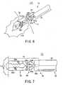
- the tissue 110can also be cut open by supplying the high frequency current to the jaws 32a and 32b, as shown in Fig. 6.
- the electrical short circuit resulting from clagged mucosa of the tissue to the jaws 32a and 32bcan be prevented between the jaws 32a and 32b.
- a blood stanching operationit is sometimes desired to simply apply a blood stanching operation to tissue 110, without gripping it.
- the tip sides of the respective jaws 32a and 32bare made to press onto a treatment-desired portion of the tissue 110.
- the jaws 32a and 32breceives high frequency current supply as stated above, whereby the desired portion of the tissue 110 coagulates simply for stop bleeding due heat caused by the current.
- This operationalso enjoys the benefit of the minimum gap ⁇ formed between the jaws 32a and 32b. That is, the gap ⁇ prevents the jaws 32a and 32b from being short-circuited with each other, while still making the high frequency current pass through the tissue 110. In this way, the tissue 110 can undergo the coagulating treatment for stop blooding in a simple manner.
- An alternative stop bleeding operationis to make sides of the respective jaws 32a and 32b press onto a desired portion of tissue 110, as shown in Fig. 8.
- the high frequency currentis supplied to the jaws 32a and 32b by applying the high frequency voltage, resulting in coagulating the pressed portion of the tissue 110 for blood stanching.
- the short circuit between the jaws 32a and 32bis prevented well due to the minimum gap ⁇ between the jaws 32a and 32b and the insulative outer surfaces of the joints 32c and 32d, whilst the current flow through the tissue 110 is secured.
- the tissue 110can be coagulated at its desired portion, for stop bleeding in a simple but steady manner.
- the present embodimentcan provide various advantages.
- the predetermined-length gap ⁇is formed between the jaws 32a and 32b and the joins 32c and 32d have the insulative outer surfaces. These structures prevent the short circuit between the jaws 32a and 32b when the jaws 32a and 32b are closed to each other.
- the bipolar forceps 10with the openable/closable gripper 32 which has the capability of gripping a desired portion of the tissue and being pressed onto (made to touch) a desired portion of the tissue without paying attention to pressing portions of the gripper 32.
- various types of high frequency medial treatmentscan be done in an easier manner.
- FIGs. 9A and 9Ba second embodiment of the high frequency treatment device according to the present invention will now be described. Incidentally, for the sake of simplified explanations, the similar or identical parts in the present and subsequent embodiments to those in the first embodiment will have the same reference numerals.
- the second embodimentcorresponds to a modification of the bipolar forces 10 explained in the first embodiment.
- the bipolar forceps 10according to the present embodiment has a link mechanism 34 different in structures from that explained in the first embodiment.
- the tip of the wire 18is divided into two so as to connect to first and second branch wires 18a and 18b which are conductive.
- the first branch wire 18ais connected to the first conducive wire 54a (refer to Fig. 2A), whereas the second branch wire 18b is connected to the second conductive wire 54b.
- the tips of the first and second wires 18a and 18bare coupled respectively with the joints 32c and 32d functioning as the bases of the jaws 32a and 32b so as to allow the joints 32c and 32d to rotate around the pin 40.
- the wires 18a and 18bhave outer surfaces on each of which an insulative layer is coated.
- First and second stoppers 18c and 18dare fixed at axial predetermined positions of the first and second branch wires 18a and 18b, respectively. The positions are decided appropriately to touch a blocker 22a formed on the inner wall surface of the sheath 22, when the wire 18 is pulled back.
- the blocker 22is positioned at an axial predetermined position of the sheath 22 and formed into a cylinder having a bore through which the two branch wires 18a and 18b are placed movably in the axial direction of the insertion member 12.
- the shapes of the first and second stoppers 18c and 18d and the blocker 22aare not limited to those shown in Figs. 9A and 9B. Any shapes can be used as long as the equivalent functions are achieved.
- the positional relationship of the first and second stoppers 18c and 18d and the blocker 22ais designed such that the first and second stoppers 18c and 18d are just made to touch the blocker 22a, when the distance (spacing) between the gripping surfaces 38a and 38b of the jaws 32a and 32b is reduced down to a predetermined minimum length ⁇ in response to pulling the wire 18 backward.
- the minimum gap length ⁇is therefore secured between the jaws 32a and 32b of the treatment member 14.
- both the length of the wire 18 and the sliding guide 62a of the operating main body 62can be adjusted so that, when the predetermined length ⁇ is established between the gripping surfaces 38a and 38b of the jaws 32a and 32b, the slider 64 is located nearest to the operating main body 62 so as not to permit the move of the slider 64 backward any more.
- the handle 16 shown in Fig. 4is operated by an operator so that the wire 18 is moved forward and backward along the sheath 22 of the insertion member 12. This operations are converted into forward and backward movements of the first and second branch wires 18a and 18b, which are then transmitted to the joints 32cand 32d.
- the jaws 32a and 32bare then operated around the pin 40 so that the jaws 32a and 32b get separated from each other or closer with each other (i.e., open and close).
- an operator's forward operation of the wire 18enables the jaws 32a and 32b to open, while an operator's backward operation of the wire 18 results in the close of the jaws 32a and 32b.
- this closing operationthe distance between the gripping surfaces 38a and 38b is gradually reduced, and finally becomes the predetermined value ⁇ just when the first and second stoppers 18c and 18d are made to touch the block 22a for a stop thereat.
- the wire 18cannot be pulled backward any more, with the result that the minimum distance ⁇ between the gripping surfaces 38a and 38b can be kept.
- the bipolar forceps 10 according to the present embodimentcan enjoy the identical advantages to those explained in the first embodiment. Additionally, the choice in design can be expanded.
- FIG. 10A and 10B to 13a third embodiment of the present embodiment will now be described.
- This embodimentrelates to another structure of the jaws.
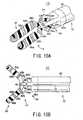
- a gripper 32 shown in Figs. 10A and 10Bhas a pair of jaws 32a and 32b, which are made from an eclectically insulative material, such as ceramics, of high heat resistance. That is, in the present embodiment, the jaws 32a and 32b cannot be used as electrodes by themselves.
- first and second electrode members 68a and 68beach made from conductive materials are arranged on each of the outer surfaces of the jaws 32a and 32b such that the electrode members are located to have a predetermined distance separation therebetween. That is, the two electrode members 68a and 68b, which are charged with positive and negative polarities, are arranged around each of the jaws 32a and 32b in a spiral and positive/negative-alternate fashion. Both of the electrode members 68a and 68b are eclectically connected with the first and second current-conducting connectors 64 and 64b via the link mechanism 34 and the wire 18, respectively.
- the operations of the bipolar forceps 10will now be described.
- the operations involving opening and closing the jaws 32a and 32b and the operations involving the closed state of the jaws 32a and 32bare similar to those explained in the first embodiment, thus omitting their detailed explanations. Since the jaws 32a and 32b have the first and second electrode members 68a and 68b spirally disposed on the outer surface of the jaws 32a and 32b along the entire axial range thereof, the jaws 32 and 32b provide the similar operations to those explained in the first embodiment.
- one jaw 32bis made to touch a desired portion of tissue 110 and high frequency vulgate is applied to the first and second electrode members 68a and 68b in the same manner as the foregoing.
- portions of the tissue 110which along the jaw 32b and each of which resides between the first and second electrode members 68a and 68b, are subjected to high frequency current flow, as shown by arrows in Fig. 11, thus leading to coagulation for blood stanching. That is, only one jaw 32b can be used for blood stanching by simply pressing the jaw 32b to a desired treatment portion of the tissue 110 and applying the high frequency voltage to the jaws 32a and 32b. This is also true of the other jaw 32a.
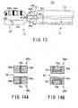
- spiral electrode members 68a and 68b on each of the jaws 32a and 32b as shown in Figs. 10A and 10Bare not always necessary.
- An alternativeis for example parallel-disposed electrode members 68a and 68b on each of the jaws 32a and 32b as shown in Figs. 12A and 12B.
- FIG. 13Another electrode structure can by shown by Fig. 13, in which the first and second electrode members 68a and 68b are disposed on only one 32a of the jaws 32a and 32b, not absolutely necessary for arranging the electrodes on both the jaws 32a and 32b. This type of jaws 32a and 32b are still able to use for both the gripping operations and the touching operations.
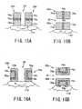
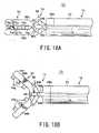
- Fig. 14Ashows a front view of jaws 32a and 32b of a gripper 32 used by a bipolar forceps 10 according to the present embodiment.
- each of the jaws 32a and 32bhas first and second electrode members 70a and 70c which are formed into rectangular prisms, respectively, and a plate-like insulator 70c rigidly sandwiched between the electrode members 70a and 70c.
- one of the jaws, 32ais composed of the first electrode member 70a, insulator 70c, and second electrode member 70c arranged in this order from the left in Fig. 14A.
- the second electrode member 70b, insulator 70c, and first electrode member 70aare aligned to form the other jaw 32b.
- the first and second electrode members 70a and 70breceive the high frequency current from positive and negative polarity terminals of the power supply unit, respectively.
- sides of the pair of jaws 32a and 32bcan be pressed onto a bleeding portion of tissue 110.
- the high frequency voltageis applied to the second electrode member 70b of one of the jaws, 32a, and the first electrode member 70a of the other jaws 32b, resulting in that the portion of the tissue 110 touching both the electrode members 70b and 70a undergo the supply of high frequency current, as indicated by an arrow in Fig. 15A.
- the tissue portion between the pair of jaws 32a and 32bis coagulated to stop bleeding. This operation is also true of the jaws 32a and 32b which have gripped a portion of the tissue 110 for treatment.
- FIG. 15BA further use of the gripper 32 is depicted as shown in Fig. 15B, in which only one of the jaws 32a and 32b is used for treatment. For example, a side of one of the jaws, 32b, is pressed onto a bleeding portion of tissue 110. In this state, the first and second electrode members 70a and 70b on the jaw 32b receives an application of high frequency voltage so that high frequency current passes through a portion residing between the electrode members 70a and 70b. Accordingly, the portion between the electrode members 70a and 70b is coagulated for blood stanching.
- each of the jaws 32a and 32bhas a U-shaped (in section) insulator 70c.
- one of the jaws, 32ais composed of a rectangular-prism-like first electrode member 70a, the U-shaped insulator 70c placed to embrace the first electrode member 70a, and a second electrode member 70b U-shaped in section and placed to embrace the insulator 70c, which are all combined rigidly.
- the other jaw 32bis also composed of the second electrode member 70b, the insulator 70c, and the first electrode member 70a and combined with each other in the same manner as the jaw 32a.
- sides of the paired jaws 32a and 32bcan be pressed onto a bleeding portion of tissue 110. This allows the tissue portion existing between the first electrode member 70a of one of the jaws, 32a, and the second electrode member 70b of the other jaw 32b to receive the flow of high frequency current. This operation is applicable to the pair of jaws 32a and 32b which has gripped a portion of the tissue 110 for high frequency treatment.
- only one of the jawsfor example, 32b, can be used for high frequency treatment such as blood stanching. That is, it is enough that one of the sides of the jaw 32b, which is opposed to the remaining jaw 32a, is pressed onto a bleeding portion. In this case, a portion residing between the first and second electrode members 70a and 70b undergoes the flow of high frequency current, thus providing the stanching operation at the pressed portion. This is also true of the other jaw 32a.
- a further variationis to arrange the electrode members 70a and 70b in only one of the jaws 32a and 32b, not always necessary for arranging them on both the jaws 32a and 32b. Still, in each or only one of the jaws 32a and 32b, a plurality of sets of positive- and negative-polarities electrode members may be formed. This structure of plural sets of electrodes can be achieved by employing two or more insulators arranged in the same manner as the above.
- a bipolar forceps 10has a tubular tip securing member 36 with a tubular member 36a, which is similar to that explained before and located at the base of the treatment member 14.
- first and second electrode members 72a and 72bOn the outer surface of the tubular member 36a, formed in the circumferential direction are first and second electrode members 72a and 72b and an insulator 72c separating the electrode members 72a and 72b from one the other. That is, the insulator 72c of a predetermined width prevents the electrode members 72a and 72b from being short-circuited.
- the first electrode member 72a of for example positive polarityis also disposed entirely on the outer surface of one of the jaws, 32a, whilst the second electrode member 72b of negative polarity is also disposed entirely on the outer surface of the jaw 32b.
- both jaws 32a and 32bfunction as a pair of electrodes, like the jaws 32a and 32b in the first embodiment.
- the first electrode member 72a on the tubular member 36a and the second electrode member 72b on the other jaw 32bare paired in that they are positionally biased on the same side in a direction perpendicular to the central axis of the insertion member 12.
- the second electrode member 72b on the tubular member 36a and the first electrode member 72a on the other jaw 32bare paired.
- the first and second electrode members 72a and 72bare electrically connected to the first and second current-conducting connectors 64a and 64b, respectively, within the sheath 22 of the insertion member 12 via the wire 18.
- the paired first electrode member 72a on the tubular member 36ais pressed together onto the portion.
- An application of high frequency voltage to the first and second electrode members 72a and 72b thus pressedallows high frequency current to flow between the jaw 32b (second electrode member 72b) and the first electrode member 72a on the tubular member 36a, as depicted by an arrow in Fig. 17. This will cause coagulation at the desired portion for blood stanching.
- the present embodimentprovides an advantage, in addition to those gained in the first embodiment. That is, in pressing the jaws 32a and 42b for blood stanching, either of the positionally biased two pairs selected from the jaws 32a and 32b and the electrodes 72 and 72b is simply pressed onto a bleeding portion of tissue 110. An example is shown in Fig. 17. In such a pressed state, the electrode members 72a and 72b is subject to the supply of high frequency current. This is a simple operation for blood stanching, shortening a time for the overall treatment operations.
- first and second electrodes 72 and 72bare not limited to that shown in Fig. 17. Further, the first electrode member 72a and the second electrode member 72b are not limited to one in number, respectively. Plural mutually-opposite-polarity electrodes can be placed on the jaw 32a (32b) at intervals, for example.
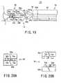
- Figs. 18A and 18Bshow a gripper of a bipolar forceps 10 according to the present embodiment, in which the gripper 32 comprises a pair of jaws 32a and 32b made from conductive materials, like the first embodiment.
- the jaws 32a and 32bfunction as electrodes by themselves.
- the jaws 32a and 32bare electrically connected to the first and second current-conducting connectors 64a and 64b via the wire 18.
- a plurality of insulators 74aare rigidly built at intervals along the longitudinal (axial) direction of the gripper 32.
- Each of the insulators 74a and 75bis formed into, for example, a cubic or a cuboid in the present embodiment, but this is not a decisive list. Any shapes such as hemisphere shape, truncated cone shape, and triangular pyramid shape can be adopted as the insulators 74a and 74b.
- the number of insulators 74a (74b)is one to five in number in the axial direction of each jaw in order to keep a sufficient gripping force.
- the insulators 74a and 74bare made from a highly insulative and heat-resistive material, for example, selected from a group consisting of ceramic material, cycloolefin resin, norbornane resin, polyether ether ketone, polyimide, polyamide, and polysufone.
- the dimensional configurationsare given to the jaws 32a and 32b such that, when the jaws 32a and 32b are closed at full, the insulators 74a and 74b on the mutually opposed gripping surfaces 38a and 38b do not interfere with each other.
- the insulators 74a and 75bare located alternately along the longitudinal direction of the gripper 32 when the closing operations of the jaws 32a and 32b are completed and a gap of slight distance is formed between the mutually adjacent insulators 74a and 74b on both the jaws 32a and 32b in the longitudinal direction.
- the portion of the tissue 110is gripped between the gripping surfaces 38a and 38b.
- the tissue portion 10is pressed onto the gripping surface 38b of one of the jaws, 32b, by the insulators 74a of the other jaw 32a and pressed onto the gripping surface 38a of the jaw 32a by the insulators 74b on the jaw 32b.
- high frequency voltageto the jaws 32a and 32b
- high frequency currentflows through the gripped tissue portion, as shown by arrows in Fig. 19.
- the gripped tissue portion 110coagulates to stop bleeding therefrom.
- FIGs. 20A and 20Bwhich pictorially depict front views of the jaws 32a and 32b composing the gripper 32.
- a plurality of rows of the insulators 74a (74b)are arranged in parallel in the longitudinal (axial) direction of the gripper 32, not limited to the arrangement in which each row of the insulators 74a (74b) is aligned in the direction perpendicular to the longitudinal direction.
- the axial length of each insulator 74a (74b)is 0.5 to 20 mm and set to an amount not to protrude from the jaws 32a and 32b.
- a seventh embodiment of the present inventionwill now be described.
- This embodimentprovides a modified example from the electrode configurations shown in the sixth embodiment in which the stoppers 34c and 34d explained in Figs. 3A and 3B are unnecessary.
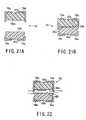
- a bipolar forceps 10has a gripper 32 shown in Figs. 21A and 21B.
- the gripper 32has jaws 32a and 32b made from insulative materials. Gripping surfaces 38a and 38b formed on the jaws 32a and 32b can be contacted to each other, as shown in Fig. 21B.
- first and second L-shaped electrode members 76a and 76bare secured with a predetermined interval therebetween.
- the first and second L-shaped electrode members 76a and 76bare secured to cover part of the upper surface and a side surface and to protrude from the lower end of the jaw 32a by a predetermined length, respectively, as shown in Fig. 21A.
- the two electrode members 76a and 76bare separated from each other by a predetermined length.
- the first and second L-shaped electrode members 76a and 76bare secured to cover part of the lower surface and part of a side surface of the jaw 32b, respectively, as shown in Fig. 21A.
- the two electrode members 76a and 76bare separated a predetermined length from each other.
- the electrode members 76a and 76breceive an application of high frequency voltage of positive and negative polarities, respectively.
- the first and second electrode members 76a and 76bcan be formed into any shapes, not limited to those expressed by Figs. 21A and 21B. Though an arbitrary number of electrode members are available for each of the first and second electrode members 76a and 76b, it is preferable to dispose two to six electrode members are disposed along the longitudinal direction of the jaws 32a and 32b when taking the arrangement areas on the jaws into account.
- the pair of jaws 32a and 32bcan also grip a portion of tissue 110 to stop bleeding from the portion.
- This gripping operationis illustrated in Fig. 22.
- high frequency voltageis applied to the first and second electrode members 76a and 76b on each of the jaws 32a and 32b so that high frequency current flows between the jaws 32a and 32b through the portion of the tissue. Hence the gripped portion is coagulated to stop bleeding.
- one-side surfaces of the jaws 32a and 32bcan be touched to the tissue 110 to apply high frequency voltage to the first and second electrode members 76a and 76b.
- high frequency currentflows between the paired first and second electrode members 76a and 76b on the paired jaws 32a and 32b, with a touched tissue portion coagulated for blood stanching.
- a high frequency treatment devicewhen it is used, is inserted into the insertion channel 102 of for example the endoscope 100 as shown in Fig. 1.
- a high frequency treatment device 200according to the present embodiment is provided with a monopolar stanching device (a coagulating device or a coagulater) 210 and a bipolar forceps (high frequency gripping forceps) 10 placed within the monopolar stanching device 210.
- the bipolar forceps 10by be, by way of example, identical in configurations to those explained in the first to seventh embodiments. Particularly in the present embodiment, the bipolar forceps 10 is identical to that in the first embodiment.
- the monopolar stanching device 210is provided with a thin and flexible insertion member 212, a treatment member 214 secured to the tip of the insertion member 212, and a current-supply connector 216 secured to the base of the insertion member 212.
- the insertion member 212is provided with a sheath 222 rotatable against the treatment member 214.
- the sheath 222is made from a resin material that exhibits an excellent flexibility.
- the sheath 222may however be formed from a metal-made flexible coil, not limited to the resin materials.
- the sheath 222has an inner diameter to form an inner tubular space through which the treatment member 12 and insertion member 14 of the bipolar forceps 10 are inserted smoothly.
- the outer diameter of the sheath 222is 1.5 to 6 mm. Particularly it is preferable if the outer diameter is 2.2 - 3.5 mm.
- a current-supply cable 218is arranged along the axial direction of the sheath 222.
- the current-supply connector 216 of the monopolar stanching device 210is a tubular connecter body 262 and a terminal 264 secured on this connector body 262.
- the connector body 262has an inner hole connecting both axial ends and the diameter of the hole is set to an amount permitting the treatment member 14 and insertion member 12 of the bipolar forceps 10 to be inserted smoothly.
- the terminal 264is electrically connected with an end of the current-supply cable 218.
- the treatment member 214is provided with a hemispheric valve 226 that has sufficient elasticity and an electrode 228 being formed from conductive material, such as elastomeric resin, and covering the valve 226.
- a hemispheric valve 226that has sufficient elasticity and an electrode 228 being formed from conductive material, such as elastomeric resin, and covering the valve 226.
- Each of the valve 226 and the electrode 228is divided by slits 230 into plural segments and formed to open and close.
- each segment of the electrode 228, which is the same in shape as each segment of the valve 226,is affixed.
- the tip of the current-supply cable 218is electrically coupled with the electrode 228. That is, the current-supply cable 218 electrically connects the electrode 228 and the terminal 264 of the current-supply connector 216.
- the segments of the electrode 228are affixed on all the segments of the valve 226, but is enough if only one electrode segment is affixed on any segment of the valve 226.
- the number of slits 230 of the valve 226, that is, the number of segments thereof,is arbitrary.
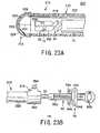
- the high frequency treatment device 200is inserted into the insertion channel of the endoscope 100 so as to make the tip of the device 200 approach a portion of tissue 110 to be treated, in which the treatment member 14 and insertion member 12 of the bipolar forceps 10 are inserted into the insertion member 212 (sheath 222) of the monopolar stanching device 210 through the tip thereof. As shown in Fig. 24A, the tip of the high frequency treatment device 200 is served by the treatment member 214 of the monopolar stanching device 210.
- the bipolar forceps 10is operated to advance toward the tip of the monopolar stanching device 210 within this device 210. Then, as shown in Fig. 24B, from the tip of the monopolar stanching device 210, the treatment device 14 of the bipolar forceps 10 is pushed out to open the valve 226 and electrode 228 of the outer device 210. In this pushing operation, since the valve 226 has elasticity, the segments of the valve 226 can be pushed aside to form an opening in an easy manner. Thus the treatment member 14 of the bipolar forceps 10 can protrude from the outer device 210.
- the treatment member 14is able to grip a portion of tissue 110 for blood stanching using the current-supplied jaws 32a and 32b.
- the monopolar stanching device 210can be used for blood stanching by having the device 210 itself pressed onto a portion of tissue.
- the high frequency treatment device 200in which the bipolar forceps 10 is contained within the monopolar stanching device 210, is operated so that its tip approaches a bleeding portion of tissue 110, as shown in Fig. 24A. And the electrode 228 on the tip of the monopolar stanching device 210 is touched to the bleeding portion and receives an application of high frequency voltage from the high frequency power supply unit. This application allows high frequency current to flow through the electrode and bleeding portion, with the blooding portion coagulated for performing blood stanching.
- a variation according to this embodimentis to replace the bipolar forceps 10 with a monopolar forceps and to replace the monopolar stanching device 210 with a bipolar stanching device.
- a high frequency treatment device 200has also a double-device structure and is provided with a bipolar forceps 10' arranged as an outer device and a monopolar stanching device 210' arranged within an insertion member 12' of the bipolar forceps 10'.
- the insertion member 12' of the forceps 10'has a tubular through-hole sufficient therein for insertion of an insertion member 212' of the monopolar stanching device 210'.
- the bipolar forceps 10'has a handle 16' with an operating main body 62', which is similar to the ones of the foregoing embodiments.
- an insertion channel 216ais formed to accept the insertion of a treatment member 214' and an insertion member 212' of the monopolar stanching device 210'.
- This insertion channel 216ahas a diameter of which amount is appropriate for a smooth insertion of the insertion member 212'.
- This high frequency treatment device 200will now be explained in terms of its operations.
- the bipolar forceps 10'functioning as part of the device 200, has the capability of stopping bleeding. Cables are used to connect both the monopolar stanching device 210' and the bipolar forceps 10' to the high frequency power supply unit.
- the high frequency treatment device 200that is, the bipolar forceps 10', is operated to make its tip approach a bleeding portion of tissue through the insertion channel 102 of the endoscope 100.
- jaws 32a' and 32b' of the bipolar forceps 10'are then driven to grip the bleeding portion and subjected to high frequency current supply.
- the device 200is operated to make its tip approach a bleeding portion of tissue. Then a gripper 32' of the bipolar forceps 10', which consists of the jaws 32a' and 32b', is opened by driving the jaws 32a' and 32b' so that its tips are rotated in the mutually different directions. After completing this open as shown in Fig. 25, the monopolar stanching device 210' is moved to protrude its treatment member 214' from the tip of the insertion member 12' of the outer forceps 10'.
- An electrode 228' on the tip of the monopolar stanching 210'is then pressed to a bleeding portion of tissue.
- the blood stanchingis achieved at the portion, like the foregoing.
- the gripper 32' of the bipolar forceps 10'can grip tissue to perform blood stanching with the aid of high frequency current. Further, any portion of the treatment member 214' of the monopolar stanching device 210' can be pressed to a bleeding portion of tissue for stanching.
- both of these stanching wayscan be used selectively depending on various bleeding conditions. That is, the single high frequency treatment device 200 has the two high frequency treatment functions, thus being convenient and efficient for the stanching operations.
Landscapes
- Health & Medical Sciences (AREA)
- Surgery (AREA)
- Engineering & Computer Science (AREA)
- Life Sciences & Earth Sciences (AREA)
- Biomedical Technology (AREA)
- Otolaryngology (AREA)
- Nuclear Medicine, Radiotherapy & Molecular Imaging (AREA)
- Plasma & Fusion (AREA)
- Physics & Mathematics (AREA)
- Heart & Thoracic Surgery (AREA)
- Medical Informatics (AREA)
- Molecular Biology (AREA)
- Animal Behavior & Ethology (AREA)
- General Health & Medical Sciences (AREA)
- Public Health (AREA)
- Veterinary Medicine (AREA)
- Surgical Instruments (AREA)
Abstract
Description
Claims (33)
- A high frequency treatment device comprising:an insertion member;a pair of jaws each representing a longitudinal direction, taking onan electrode function along an entire region of each jaw in thelongitudinal direction, and having a gripping surface;a link member holding the pair of jaws to be opened and closed ina direction allowing the gripping surfaces of the jaws to be opposed toeach other and linking the pair of jaws to a tip of the insertion member ina condition in which an electrical insulation between the jaws is kept;a short-circuit preventing member preventing an electrical shortcircuit between the jaws when the jaws are closed to each other;a power line being disposed through the insertion member andapplying a high frequency voltage to the jaws via the link member tocause a high frequency current to flow through the jaws; andan operation wire being disposed through the insertion memberand transmitting open/close movements to the jaws via the link member.
- The device according to claim 1, wherein the short-circuitpreventing member is formed in either one of the link member and theinsertion member.
- The device according to claim 2, wherein each of the pairedjaws is made from a conductive material to serve as an electrode incharge of the electrode function.
- The device according to claim 3, wherein each of the pairedjaws serves as one of positive and negative electrodes to which the highfrequency voltage is applied.
- The device according to claim 4, wherein the short-circuitpreventing member is provided with a limiting member to limit a rotationrange of each of the paired jaws in a closing direction along which eachjaw is rotated, the rotation range being set to secure a gap ofpredetermined length between the jaws which are closed at full.
- The device according to claim 5, wherein the link memberincludes two links respectively coupled with the paired jaws and
the limiting member includes two pins each secured to each of thetwo links and configured to interfere with an arm secured to the insertionmember to limit the rotation range of each jaw in the closing direction. - The device according to claim 6, wherein the link memberincludes two jaw sustainers intervening between bases of the paired jawsand the two links, respectively, at least one of the jaw sustainers havingan electrically insulative outer surface.
- The device according to claim 4, wherein the gripping surfacesof the paired jaws have irregularities, respectively.
- The device according to claim 4, wherein the short-circuitpreventing member comprises two wires linking the operation wire andtwo jaw sustainers rigidly coupled with bases of the respective jaws in theinsertion member and a stopper stopping a movement of the two wires ata predetermined position in a movement direction of the two wirescorresponding to the closing direction of the jaws.
- The device according to claim 4, wherein each of the pairedjaws receives an application of the high frequency voltage through thepower line to take on the positive and negative electrodes and conductivesurfaces are formed on outer surfaces of the tip of the insertion member,the conductive surfaces being positionally face to face to the jaws andreceiving the application of the high frequency voltage but being oppositeto the jaws in polarities.
- The device according to claim 3, wherein each of the pairedjaws comprises two electrodes providing the electrode function and aninsulator placed between the two electrodes, the two electrodes and theinsulator being disposed in the longitudinal direction.
- The device according to claim 11, wherein the mutually facedtwo electrodes of the two paired jaws are configured to receive an application of the high frequency voltage of mutually different polaritiesvia the power line.
- The device according to claim 12, wherein the insulator is aflat insulator when viewing the paired jaws along the longitudinaldirection.
- The device according to claim 12, wherein the insulator is aU-shaped-section insulator when viewing the paired jaws along thelongitudinal direction.
- The device according to claim 1, wherein the short-circuitpreventing member is composed of a plurality of insulators protrudedfrom the griping surfaces of the paired jaws, the plurality of insulatorsaligning alternately in the longitudinal direction when the paired jaws areclosed at full.
- The device according to claim 1, wherein at least one of thepaired jaws comprises an electrically insulative jaw body; and positiveand negative electrodes serving as the electrode function by receiving anapplication of the high frequency voltage and being disposed through anentire region on an outer surface of each jaw body in the longitudinaldirection.
- The device according to claim 16, wherein the positive andnegative electrodes are disposed on the outer surface of at least one of thejaw bodies by one pair.
- The device according to claim 16, wherein the positive andnegative electrodes are wound around the outer surface of at least one ofthe jaw bodies.
- The device according to claim 16, wherein the positive andnegative electrodes are disposed on the outer surface of at least one of thejaw bodies by a plurality of pairs.
- The device according to claim 16, wherein the positive andnegative electrodes are linearly disposed on the outer surface of at leastone of the jaw bodies.
- The device according to claim 16, wherein the positive andnegative electrodes are disposed on the outer surface of each of the jawbodies.
- The device according to claim 16, wherein the positive andnegative electrodes are disposed on the outer surface of only one of thejaw bodies.
- The device according to claim 21, wherein the two jaw bodiesare structured to make the gripping surfaces come in contact with eachother when the two jaws are closed,
the positive and negative electrodes are disposed on the outersurface of each of the two jaw bodies along the longitudinal direction, thepositive and negative electrodes on one of the two jaw bodies protrudingfrom a level of the gripping surface and the mutually neighboringelectrodes on the two jaw bodies being set to receive the high frequencyvoltages of which polarities are opposite to each other. - A high frequency treatment device comprising:wherein one of the insertion member of the bipolar forceps and thefurther insertion member of the coagulating device is contained withinthe other one such that a tip of one of the insertion member of the bipolarforceps and the further insertion member of the coagulating device isretractably protruded from a tip of the other one.a bipolar forceps composed of the high frequency treatment deviceaccording to claim 1; anda coagulating device having
a further insertion member and
an electrode disposed on a tip of the further insertionmember and configured to treat a portion of tissue to which the electrodeis touched with a high frequency voltage applied to the electrode, - A high frequency treatment device comprising:wherein one of the first insertion member of the high frequencyforceps and the second insertion member of the coagulating device iscontained within the other one such that a tip of one of the first insertionmember of the high frequency forceps and the second insertion memberof the coagulating device is retractably protruded from a tip of the otherone.a high frequency forceps equipped with
a first insertion member;
a gripper disposed at a tip of the first insertion memberand configured to have a pair of jaws openable and closable to grip aportion of tissue;
a handle coupled with a base of the first insertion memberand used to open and close the jaws; and
an electrode given to at least one of the jaws andconfigured to treat a portion of tissue in a condition under which theelectrode to which a high frequency voltage is applied is touched to theportion of the tissue, anda coagulating device equipped with
a second insertion member and
an electrode disposed on a tip of the second insertionmember and configured to coagulate or cut open a portion of tissue towhich the electrode is touched with a high frequency voltage applied tothe electrode, - The device according to claim 25, wherein the high frequencyforceps is a bipolar type of high frequency forceps and the coagulatingdevice is a monopolar type of coagulating device.
- The device according to claim 25, wherein the first insertionmember is contained in the second insertion member when the highfrequency forceps is unused and the tip of the first insertion member ispossible to protrude from the tip of the second insertion member.
- The device according to claim 25, wherein the secondinsertion member is contained in the first insertion member when the coagulating device is unused and the tip of the second insertion memberis possible to protrude from the tip of the first insertion member.
- A high frequency treatment device comprising:wherein each of the first and second jaws has a gripping surfaceused for the gripping, a back surface located back to back to the grippingsurface, a first and second side surfaces each connecting the backsurface and the gripping surface, and one or more pairs of positive andnegative electrodes,an insertion member insertable into a body of an object to beexamined;a pair of jaws being disposed at a tip of the insertion member andconsisting of a first and second jaws gripping a portion of tissue to betreated of the object; anda handle coupled with a base of the insertion member and usedfor opening and closing the jaws,
wherein both of the positive and negative electrodes are exposedon the back surface of each of the first and second jaws,
at least one of both the positive and negative electrodes is exposed,at least one in number, on the gripping surface of the first jaw,
at least one of both the positive and negative electrodes is exposed,at least one in number, on the first and second side surfaces of the firstjaw,
at least one electrode opposite in polarity to the electrodesexposed on the gripping surface of the fist jaw is exposed on the gripingsurface of the second jaw, and
at least one electrode opposite in polarity to the electrodesexposed on the first and second side surfaces of the first jaw is exposedon the first and second side surfaces of the second jaw. - The device according to claim 29, wherein each of the firstand second jaws comprises an insulator separating the positive andnegative electrodes from each other.
- The device according to claim 30, wherein the insulator is aflat insulator when viewing the first and second jaws along a longitudinal direction of the jaws and the flat insulator is placed between the positiveand negative electrodes.
- The device according to claim 30, wherein the insulator is anapproximately U-shaped insulator directed to be exposed on the backsurface when viewing the first and second jaws along a longitudinaldirection of the jaws and the flat insulator is placed between the positiveand negative electrodes.
- The device according to claim 30, comprising:a link member holding the pair of jaws to be opened and closed ina direction allowing the gripping surfaces of the jaws to be opposed toeach other and linking the pair of jaws to a tip of the insertion member ina state in which an electrical insulation between the jaws is kept;a short-circuit preventing member preventing an electrical shortcircuit between the jaws when the jaws are closed to each other;a power line being disposed through the insertion member andapplying a high frequency voltage to the jaws via the link member, thehigh frequency voltage causing a high frequency current; andan operation wire being disposed through the insertion memberand transmitting open/close movements to the jaws via the link member.
Applications Claiming Priority (2)
| Application Number | Priority Date | Filing Date | Title |
|---|---|---|---|
| JP2004050212AJP4436698B2 (en) | 2004-02-25 | 2004-02-25 | High frequency treatment tool |
| JP2004050212 | 2004-02-25 |
Publications (2)
| Publication Number | Publication Date |
|---|---|
| EP1568330A1true EP1568330A1 (en) | 2005-08-31 |
| EP1568330B1 EP1568330B1 (en) | 2016-11-30 |
Family
ID=34747480
Family Applications (1)
| Application Number | Title | Priority Date | Filing Date |
|---|---|---|---|
| EP05004146.6AExpired - LifetimeEP1568330B1 (en) | 2004-02-25 | 2005-02-25 | High frequency treatment device having a pair of jaws with electrodes |
Country Status (3)
| Country | Link |
|---|---|
| US (1) | US7621910B2 (en) |
| EP (1) | EP1568330B1 (en) |
| JP (1) | JP4436698B2 (en) |
Cited By (66)
| Publication number | Priority date | Publication date | Assignee | Title |
|---|---|---|---|---|
| EP1747762A2 (en) | 2005-07-26 | 2007-01-31 | Aesculap AG & Co. KG | Coagulation forceps for surgical applications |
| WO2007093351A1 (en)* | 2006-02-14 | 2007-08-23 | Erbe Elektromedizin Gmbh | Electrosurgical instrument and type series for electrosurgical instruments |
| EP1878400A1 (en)* | 2006-07-11 | 2008-01-16 | Olympus Medical Systems Corp. | Treatment device |
| WO2009032623A3 (en)* | 2007-08-31 | 2009-07-23 | Ethicon Endo Surgery Inc | Electrical albation surgical instruments |
| WO2009067649A3 (en)* | 2007-11-21 | 2009-08-27 | Ethicon Endo-Surgery, Inc. | Bipolar forceps having a cutting element |
| US7655004B2 (en) | 2007-02-15 | 2010-02-02 | Ethicon Endo-Surgery, Inc. | Electroporation ablation apparatus, system, and method |
| US7815662B2 (en) | 2007-03-08 | 2010-10-19 | Ethicon Endo-Surgery, Inc. | Surgical suture anchors and deployment device |
| WO2011018154A1 (en)* | 2009-08-14 | 2011-02-17 | Erbe Elektromedizin Gmbh | Electrosurgical instrument |
| US8037591B2 (en) | 2009-02-02 | 2011-10-18 | Ethicon Endo-Surgery, Inc. | Surgical scissors |
| US8070759B2 (en) | 2008-05-30 | 2011-12-06 | Ethicon Endo-Surgery, Inc. | Surgical fastening device |
| US8075572B2 (en) | 2007-04-26 | 2011-12-13 | Ethicon Endo-Surgery, Inc. | Surgical suturing apparatus |
| US8100922B2 (en) | 2007-04-27 | 2012-01-24 | Ethicon Endo-Surgery, Inc. | Curved needle suturing tool |
| US8114072B2 (en) | 2008-05-30 | 2012-02-14 | Ethicon Endo-Surgery, Inc. | Electrical ablation device |
| US8114119B2 (en) | 2008-09-09 | 2012-02-14 | Ethicon Endo-Surgery, Inc. | Surgical grasping device |
| US8157834B2 (en) | 2008-11-25 | 2012-04-17 | Ethicon Endo-Surgery, Inc. | Rotational coupling device for surgical instrument with flexible actuators |
| US8172772B2 (en) | 2008-12-11 | 2012-05-08 | Ethicon Endo-Surgery, Inc. | Specimen retrieval device |
| US8211125B2 (en) | 2008-08-15 | 2012-07-03 | Ethicon Endo-Surgery, Inc. | Sterile appliance delivery device for endoscopic procedures |
| US8241204B2 (en) | 2008-08-29 | 2012-08-14 | Ethicon Endo-Surgery, Inc. | Articulating end cap |
| EP2489314A1 (en)* | 2010-11-19 | 2012-08-22 | Tyco Health Group LP | Apparatus for performing an electrosurgical procedure |
| US8252057B2 (en) | 2009-01-30 | 2012-08-28 | Ethicon Endo-Surgery, Inc. | Surgical access device |
| US8262563B2 (en) | 2008-07-14 | 2012-09-11 | Ethicon Endo-Surgery, Inc. | Endoscopic translumenal articulatable steerable overtube |
| US8262655B2 (en) | 2007-11-21 | 2012-09-11 | Ethicon Endo-Surgery, Inc. | Bipolar forceps |
| US8262680B2 (en) | 2008-03-10 | 2012-09-11 | Ethicon Endo-Surgery, Inc. | Anastomotic device |
| US8317806B2 (en) | 2008-05-30 | 2012-11-27 | Ethicon Endo-Surgery, Inc. | Endoscopic suturing tension controlling and indication devices |
| US8337394B2 (en) | 2008-10-01 | 2012-12-25 | Ethicon Endo-Surgery, Inc. | Overtube with expandable tip |
| US8353487B2 (en) | 2009-12-17 | 2013-01-15 | Ethicon Endo-Surgery, Inc. | User interface support devices for endoscopic surgical instruments |
| US8361066B2 (en) | 2009-01-12 | 2013-01-29 | Ethicon Endo-Surgery, Inc. | Electrical ablation devices |
| US8361112B2 (en) | 2008-06-27 | 2013-01-29 | Ethicon Endo-Surgery, Inc. | Surgical suture arrangement |
| US8403926B2 (en) | 2008-06-05 | 2013-03-26 | Ethicon Endo-Surgery, Inc. | Manually articulating devices |
| US8409200B2 (en) | 2008-09-03 | 2013-04-02 | Ethicon Endo-Surgery, Inc. | Surgical grasping device |
| US8480657B2 (en) | 2007-10-31 | 2013-07-09 | Ethicon Endo-Surgery, Inc. | Detachable distal overtube section and methods for forming a sealable opening in the wall of an organ |
| US8480689B2 (en) | 2008-09-02 | 2013-07-09 | Ethicon Endo-Surgery, Inc. | Suturing device |
| US8496574B2 (en) | 2009-12-17 | 2013-07-30 | Ethicon Endo-Surgery, Inc. | Selectively positionable camera for surgical guide tube assembly |
| US8506564B2 (en) | 2009-12-18 | 2013-08-13 | Ethicon Endo-Surgery, Inc. | Surgical instrument comprising an electrode |
| US8529563B2 (en) | 2008-08-25 | 2013-09-10 | Ethicon Endo-Surgery, Inc. | Electrical ablation devices |
| US8568410B2 (en) | 2007-08-31 | 2013-10-29 | Ethicon Endo-Surgery, Inc. | Electrical ablation surgical instruments |
| US8579897B2 (en) | 2007-11-21 | 2013-11-12 | Ethicon Endo-Surgery, Inc. | Bipolar forceps |
| US8608652B2 (en) | 2009-11-05 | 2013-12-17 | Ethicon Endo-Surgery, Inc. | Vaginal entry surgical devices, kit, system, and method |
| US8652150B2 (en) | 2008-05-30 | 2014-02-18 | Ethicon Endo-Surgery, Inc. | Multifunction surgical device |
| EP2486876A4 (en)* | 2009-10-08 | 2014-02-19 | River Seiko Ltd Company | SCISSORS FOR ENDOSCOPE |
| US8679003B2 (en) | 2008-05-30 | 2014-03-25 | Ethicon Endo-Surgery, Inc. | Surgical device and endoscope including same |
| US8771260B2 (en) | 2008-05-30 | 2014-07-08 | Ethicon Endo-Surgery, Inc. | Actuating and articulating surgical device |
| US8828031B2 (en) | 2009-01-12 | 2014-09-09 | Ethicon Endo-Surgery, Inc. | Apparatus for forming an anastomosis |
| US8888792B2 (en) | 2008-07-14 | 2014-11-18 | Ethicon Endo-Surgery, Inc. | Tissue apposition clip application devices and methods |
| US8906035B2 (en) | 2008-06-04 | 2014-12-09 | Ethicon Endo-Surgery, Inc. | Endoscopic drop off bag |
| US8939897B2 (en) | 2007-10-31 | 2015-01-27 | Ethicon Endo-Surgery, Inc. | Methods for closing a gastrotomy |
| US8986199B2 (en) | 2012-02-17 | 2015-03-24 | Ethicon Endo-Surgery, Inc. | Apparatus and methods for cleaning the lens of an endoscope |
| US9005198B2 (en) | 2010-01-29 | 2015-04-14 | Ethicon Endo-Surgery, Inc. | Surgical instrument comprising an electrode |
| US9028483B2 (en) | 2009-12-18 | 2015-05-12 | Ethicon Endo-Surgery, Inc. | Surgical instrument comprising an electrode |
| CN104619274A (en)* | 2012-11-13 | 2015-05-13 | 奥林巴斯医疗株式会社 | Treatment tool for endoscope |
| US9049987B2 (en) | 2011-03-17 | 2015-06-09 | Ethicon Endo-Surgery, Inc. | Hand held surgical device for manipulating an internal magnet assembly within a patient |
| US9078662B2 (en) | 2012-07-03 | 2015-07-14 | Ethicon Endo-Surgery, Inc. | Endoscopic cap electrode and method for using the same |
| US9226772B2 (en) | 2009-01-30 | 2016-01-05 | Ethicon Endo-Surgery, Inc. | Surgical device |
| EP2926754A3 (en)* | 2014-04-02 | 2016-01-06 | Covidien LP | Electrosurgical devices including transverse electrode configurations |
| US9233241B2 (en) | 2011-02-28 | 2016-01-12 | Ethicon Endo-Surgery, Inc. | Electrical ablation devices and methods |
| US9254169B2 (en) | 2011-02-28 | 2016-02-09 | Ethicon Endo-Surgery, Inc. | Electrical ablation devices and methods |
| US9277957B2 (en) | 2012-08-15 | 2016-03-08 | Ethicon Endo-Surgery, Inc. | Electrosurgical devices and methods |
| US9314620B2 (en) | 2011-02-28 | 2016-04-19 | Ethicon Endo-Surgery, Inc. | Electrical ablation devices and methods |
| US9427255B2 (en) | 2012-05-14 | 2016-08-30 | Ethicon Endo-Surgery, Inc. | Apparatus for introducing a steerable camera assembly into a patient |
| US9545290B2 (en) | 2012-07-30 | 2017-01-17 | Ethicon Endo-Surgery, Inc. | Needle probe guide |
| US9572623B2 (en) | 2012-08-02 | 2017-02-21 | Ethicon Endo-Surgery, Inc. | Reusable electrode and disposable sheath |
| JPWO2015029518A1 (en)* | 2013-08-29 | 2017-03-02 | オリンパス株式会社 | Grasping treatment device and grasping unit |
| US10058377B2 (en) | 2014-04-02 | 2018-08-28 | Covidien Lp | Electrosurgical devices including transverse electrode configurations |
| US10092291B2 (en) | 2011-01-25 | 2018-10-09 | Ethicon Endo-Surgery, Inc. | Surgical instrument with selectively rigidizable features |
| US10098527B2 (en) | 2013-02-27 | 2018-10-16 | Ethidcon Endo-Surgery, Inc. | System for performing a minimally invasive surgical procedure |
| US10314649B2 (en) | 2012-08-02 | 2019-06-11 | Ethicon Endo-Surgery, Inc. | Flexible expandable electrode and method of intraluminal delivery of pulsed power |
Families Citing this family (226)
| Publication number | Priority date | Publication date | Assignee | Title |
|---|---|---|---|---|
| US6267761B1 (en)* | 1997-09-09 | 2001-07-31 | Sherwood Services Ag | Apparatus and method for sealing and cutting tissue |
| US7435249B2 (en) | 1997-11-12 | 2008-10-14 | Covidien Ag | Electrosurgical instruments which reduces collateral damage to adjacent tissue |
| US6726686B2 (en) | 1997-11-12 | 2004-04-27 | Sherwood Services Ag | Bipolar electrosurgical instrument for sealing vessels |
| US6228083B1 (en) | 1997-11-14 | 2001-05-08 | Sherwood Services Ag | Laparoscopic bipolar electrosurgical instrument |
| US7582087B2 (en) | 1998-10-23 | 2009-09-01 | Covidien Ag | Vessel sealing instrument |
| US7267677B2 (en) | 1998-10-23 | 2007-09-11 | Sherwood Services Ag | Vessel sealing instrument |
| US7364577B2 (en) | 2002-02-11 | 2008-04-29 | Sherwood Services Ag | Vessel sealing system |
| US7118570B2 (en) | 2001-04-06 | 2006-10-10 | Sherwood Services Ag | Vessel sealing forceps with disposable electrodes |
| US20040249374A1 (en) | 1998-10-23 | 2004-12-09 | Tetzlaff Philip M. | Vessel sealing instrument |
| US7887535B2 (en) | 1999-10-18 | 2011-02-15 | Covidien Ag | Vessel sealing wave jaw |
| US20030109875A1 (en) | 1999-10-22 | 2003-06-12 | Tetzlaff Philip M. | Open vessel sealing forceps with disposable electrodes |
| EP1527747B1 (en) | 2001-04-06 | 2015-09-30 | Covidien AG | Electrosurgical instrument which reduces collateral damage to adjacent tissue |
| AU2001249937B2 (en) | 2001-04-06 | 2006-02-09 | Covidien Ag | Vessel sealing instrument |
| US10849681B2 (en) | 2001-04-06 | 2020-12-01 | Covidien Ag | Vessel sealer and divider |
| ES2262639T3 (en) | 2001-04-06 | 2006-12-01 | Sherwood Services Ag | SHUTTER AND DIVIDER OF GLASSES WITH BUMPER MEMBERS N OCONDUCTIVES. |
| US7101371B2 (en) | 2001-04-06 | 2006-09-05 | Dycus Sean T | Vessel sealer and divider |
| US7931649B2 (en) | 2002-10-04 | 2011-04-26 | Tyco Healthcare Group Lp | Vessel sealing instrument with electrical cutting mechanism |
| US7270664B2 (en) | 2002-10-04 | 2007-09-18 | Sherwood Services Ag | Vessel sealing instrument with electrical cutting mechanism |
| US7276068B2 (en) | 2002-10-04 | 2007-10-02 | Sherwood Services Ag | Vessel sealing instrument with electrical cutting mechanism |
| US7799026B2 (en) | 2002-11-14 | 2010-09-21 | Covidien Ag | Compressible jaw configuration with bipolar RF output electrodes for soft tissue fusion |
| US7033354B2 (en)* | 2002-12-10 | 2006-04-25 | Sherwood Services Ag | Electrosurgical electrode having a non-conductive porous ceramic coating |
| EP1601298B1 (en) | 2003-03-13 | 2016-09-07 | Covidien AG | Bipolar concentric electrode assembly for soft tissue fusion |
| CA2523675C (en) | 2003-05-01 | 2016-04-26 | Sherwood Services Ag | Electrosurgical instrument which reduces thermal damage to adjacent tissue |
| US7160299B2 (en) | 2003-05-01 | 2007-01-09 | Sherwood Services Ag | Method of fusing biomaterials with radiofrequency energy |
| US8128624B2 (en) | 2003-05-01 | 2012-03-06 | Covidien Ag | Electrosurgical instrument that directs energy delivery and protects adjacent tissue |
| JP5137230B2 (en) | 2003-05-15 | 2013-02-06 | コヴィディエン・アクチェンゲゼルシャフト | Tissue sealer with non-conductive variable stop member and method for sealing tissue |
| USD956973S1 (en) | 2003-06-13 | 2022-07-05 | Covidien Ag | Movable handle for endoscopic vessel sealer and divider |
| US7150749B2 (en) | 2003-06-13 | 2006-12-19 | Sherwood Services Ag | Vessel sealer and divider having elongated knife stroke and safety cutting mechanism |
| US7156846B2 (en) | 2003-06-13 | 2007-01-02 | Sherwood Services Ag | Vessel sealer and divider for use with small trocars and cannulas |
| US7857812B2 (en) | 2003-06-13 | 2010-12-28 | Covidien Ag | Vessel sealer and divider having elongated knife stroke and safety for cutting mechanism |
| US7597693B2 (en) | 2003-06-13 | 2009-10-06 | Covidien Ag | Vessel sealer and divider for use with small trocars and cannulas |
| US20040260337A1 (en) | 2003-06-18 | 2004-12-23 | Scimed Life Systems, Inc. | Endoscopic instruments and methods of manufacture |
| US8469993B2 (en) | 2003-06-18 | 2013-06-25 | Boston Scientific Scimed, Inc. | Endoscopic instruments |
| US7951165B2 (en)* | 2003-08-18 | 2011-05-31 | Boston Scientific Scimed, Inc. | Endoscopic medical instrument and related methods of use |
| US9848938B2 (en) | 2003-11-13 | 2017-12-26 | Covidien Ag | Compressible jaw configuration with bipolar RF output electrodes for soft tissue fusion |
| US7367976B2 (en)* | 2003-11-17 | 2008-05-06 | Sherwood Services Ag | Bipolar forceps having monopolar extension |
| US7232440B2 (en) | 2003-11-17 | 2007-06-19 | Sherwood Services Ag | Bipolar forceps having monopolar extension |
| US7500975B2 (en) | 2003-11-19 | 2009-03-10 | Covidien Ag | Spring loaded reciprocating tissue cutting mechanism in a forceps-style electrosurgical instrument |
| US7811283B2 (en) | 2003-11-19 | 2010-10-12 | Covidien Ag | Open vessel sealing instrument with hourglass cutting mechanism and over-ratchet safety |
| US7131970B2 (en) | 2003-11-19 | 2006-11-07 | Sherwood Services Ag | Open vessel sealing instrument with cutting mechanism |
| US7442193B2 (en) | 2003-11-20 | 2008-10-28 | Covidien Ag | Electrically conductive/insulative over-shoe for tissue fusion |
| US7780662B2 (en) | 2004-03-02 | 2010-08-24 | Covidien Ag | Vessel sealing system using capacitive RF dielectric heating |
| US20060041252A1 (en)* | 2004-08-17 | 2006-02-23 | Odell Roger C | System and method for monitoring electrosurgical instruments |
| US7195631B2 (en) | 2004-09-09 | 2007-03-27 | Sherwood Services Ag | Forceps with spring loaded end effector assembly |
| US7540872B2 (en) | 2004-09-21 | 2009-06-02 | Covidien Ag | Articulating bipolar electrosurgical instrument |
| US7955332B2 (en) | 2004-10-08 | 2011-06-07 | Covidien Ag | Mechanism for dividing tissue in a hemostat-style instrument |
| US7686827B2 (en) | 2004-10-21 | 2010-03-30 | Covidien Ag | Magnetic closure mechanism for hemostat |
| US7686804B2 (en) | 2005-01-14 | 2010-03-30 | Covidien Ag | Vessel sealer and divider with rotating sealer and cutter |
| US7909823B2 (en) | 2005-01-14 | 2011-03-22 | Covidien Ag | Open vessel sealing instrument |
| US7491202B2 (en) | 2005-03-31 | 2009-02-17 | Covidien Ag | Electrosurgical forceps with slow closure sealing plates and method of sealing tissue |
| US7762960B2 (en) | 2005-05-13 | 2010-07-27 | Boston Scientific Scimed, Inc. | Biopsy forceps assemblies |
| US7837685B2 (en) | 2005-07-13 | 2010-11-23 | Covidien Ag | Switch mechanisms for safe activation of energy on an electrosurgical instrument |
| US7628791B2 (en) | 2005-08-19 | 2009-12-08 | Covidien Ag | Single action tissue sealer |
| CA2561034C (en) | 2005-09-30 | 2014-12-09 | Sherwood Services Ag | Flexible endoscopic catheter with an end effector for coagulating and transfecting tissue |
| US7789878B2 (en) | 2005-09-30 | 2010-09-07 | Covidien Ag | In-line vessel sealer and divider |
| US7722607B2 (en) | 2005-09-30 | 2010-05-25 | Covidien Ag | In-line vessel sealer and divider |
| US7879035B2 (en) | 2005-09-30 | 2011-02-01 | Covidien Ag | Insulating boot for electrosurgical forceps |
| US7922953B2 (en) | 2005-09-30 | 2011-04-12 | Covidien Ag | Method for manufacturing an end effector assembly |
| ES2381560T3 (en) | 2005-09-30 | 2012-05-29 | Covidien Ag | Insulating sleeve for electrosurgical forceps |
| US7594916B2 (en) | 2005-11-22 | 2009-09-29 | Covidien Ag | Electrosurgical forceps with energy based tissue division |
| US8882766B2 (en) | 2006-01-24 | 2014-11-11 | Covidien Ag | Method and system for controlling delivery of energy to divide tissue |
| US8241282B2 (en) | 2006-01-24 | 2012-08-14 | Tyco Healthcare Group Lp | Vessel sealing cutting assemblies |
| US7766910B2 (en) | 2006-01-24 | 2010-08-03 | Tyco Healthcare Group Lp | Vessel sealer and divider for large tissue structures |
| US8734443B2 (en) | 2006-01-24 | 2014-05-27 | Covidien Lp | Vessel sealer and divider for large tissue structures |
| US8298232B2 (en) | 2006-01-24 | 2012-10-30 | Tyco Healthcare Group Lp | Endoscopic vessel sealer and divider for large tissue structures |
| US8007494B1 (en) | 2006-04-27 | 2011-08-30 | Encision, Inc. | Device and method to prevent surgical burns |
| US20070255278A1 (en)* | 2006-04-28 | 2007-11-01 | Nobis Rudolph H | Apparatus and method for deploying a cutting element during an endoscopic mucosal resection |
| US7641653B2 (en) | 2006-05-04 | 2010-01-05 | Covidien Ag | Open vessel sealing forceps disposable handswitch |
| US7846158B2 (en) | 2006-05-05 | 2010-12-07 | Covidien Ag | Apparatus and method for electrode thermosurgery |
| US20070282329A1 (en)* | 2006-05-30 | 2007-12-06 | Pentax Corporation | Bipolar high-frequency incision tool for an endoscope |
| US20070282331A1 (en)* | 2006-05-30 | 2007-12-06 | Pentax Corporation | Bipolar high-frequency incision tool for an endoscope |
| US20070282330A1 (en)* | 2006-05-30 | 2007-12-06 | Pentax Corporation | Bipolar high-frequency treatment tool for an endoscope |
| US8251989B1 (en) | 2006-06-13 | 2012-08-28 | Encision, Inc. | Combined bipolar and monopolar electrosurgical instrument and method |
| US7776037B2 (en) | 2006-07-07 | 2010-08-17 | Covidien Ag | System and method for controlling electrode gap during tissue sealing |
| US7744615B2 (en) | 2006-07-18 | 2010-06-29 | Covidien Ag | Apparatus and method for transecting tissue on a bipolar vessel sealing instrument |
| US7731717B2 (en) | 2006-08-08 | 2010-06-08 | Covidien Ag | System and method for controlling RF output during tissue sealing |
| US8597297B2 (en) | 2006-08-29 | 2013-12-03 | Covidien Ag | Vessel sealing instrument with multiple electrode configurations |
| US8070746B2 (en) | 2006-10-03 | 2011-12-06 | Tyco Healthcare Group Lp | Radiofrequency fusion of cardiac tissue |
| US7951149B2 (en) | 2006-10-17 | 2011-05-31 | Tyco Healthcare Group Lp | Ablative material for use with tissue treatment device |
| US7785060B2 (en)* | 2006-10-27 | 2010-08-31 | Applied Materials, Inc. | Multi-directional mechanical scanning in an ion implanter |
| US7935130B2 (en) | 2006-11-16 | 2011-05-03 | Intuitive Surgical Operations, Inc. | Two-piece end-effectors for robotic surgical tools |
| USD649249S1 (en) | 2007-02-15 | 2011-11-22 | Tyco Healthcare Group Lp | End effectors of an elongated dissecting and dividing instrument |
| CN101677812B (en) | 2007-03-23 | 2013-06-12 | 显著外科技术公司 | Surgical device and method of use thereof |
| US8267935B2 (en) | 2007-04-04 | 2012-09-18 | Tyco Healthcare Group Lp | Electrosurgical instrument reducing current densities at an insulator conductor junction |
| US7877852B2 (en) | 2007-09-20 | 2011-02-01 | Tyco Healthcare Group Lp | Method of manufacturing an end effector assembly for sealing tissue |
| US7877853B2 (en) | 2007-09-20 | 2011-02-01 | Tyco Healthcare Group Lp | Method of manufacturing end effector assembly for sealing tissue |
| US8235993B2 (en) | 2007-09-28 | 2012-08-07 | Tyco Healthcare Group Lp | Insulating boot for electrosurgical forceps with exohinged structure |
| US8251996B2 (en) | 2007-09-28 | 2012-08-28 | Tyco Healthcare Group Lp | Insulating sheath for electrosurgical forceps |
| US8267936B2 (en) | 2007-09-28 | 2012-09-18 | Tyco Healthcare Group Lp | Insulating mechanically-interfaced adhesive for electrosurgical forceps |
| US9023043B2 (en) | 2007-09-28 | 2015-05-05 | Covidien Lp | Insulating mechanically-interfaced boot and jaws for electrosurgical forceps |
| AU2008221509B2 (en) | 2007-09-28 | 2013-10-10 | Covidien Lp | Dual durometer insulating boot for electrosurgical forceps |
| US8236025B2 (en) | 2007-09-28 | 2012-08-07 | Tyco Healthcare Group Lp | Silicone insulated electrosurgical forceps |
| US8235992B2 (en) | 2007-09-28 | 2012-08-07 | Tyco Healthcare Group Lp | Insulating boot with mechanical reinforcement for electrosurgical forceps |
| US8221416B2 (en) | 2007-09-28 | 2012-07-17 | Tyco Healthcare Group Lp | Insulating boot for electrosurgical forceps with thermoplastic clevis |
| JP4726015B2 (en)* | 2007-10-12 | 2011-07-20 | 有限会社リバー精工 | Endoscopic high-frequency treatment instrument for endoscope |
| US8764748B2 (en) | 2008-02-06 | 2014-07-01 | Covidien Lp | End effector assembly for electrosurgical device and method for making the same |
| US8623276B2 (en) | 2008-02-15 | 2014-01-07 | Covidien Lp | Method and system for sterilizing an electrosurgical instrument |
| JP5380705B2 (en) | 2008-05-15 | 2014-01-08 | 株式会社リバーセイコー | Endoscopic high frequency hemostatic forceps |
| JP5403959B2 (en)* | 2008-07-08 | 2014-01-29 | オリンパスメディカルシステムズ株式会社 | High frequency treatment tool |
| US9204923B2 (en)* | 2008-07-16 | 2015-12-08 | Intuitive Surgical Operations, Inc. | Medical instrument electronically energized using drive cables |
| US8469956B2 (en) | 2008-07-21 | 2013-06-25 | Covidien Lp | Variable resistor jaw |
| US8162973B2 (en) | 2008-08-15 | 2012-04-24 | Tyco Healthcare Group Lp | Method of transferring pressure in an articulating surgical instrument |
| US8257387B2 (en) | 2008-08-15 | 2012-09-04 | Tyco Healthcare Group Lp | Method of transferring pressure in an articulating surgical instrument |
| US8500728B2 (en) | 2008-08-18 | 2013-08-06 | Encision, Inc. | Enhanced control systems including flexible shielding and support systems for electrosurgical applications |
| US9833281B2 (en) | 2008-08-18 | 2017-12-05 | Encision Inc. | Enhanced control systems including flexible shielding and support systems for electrosurgical applications |
| US9603652B2 (en) | 2008-08-21 | 2017-03-28 | Covidien Lp | Electrosurgical instrument including a sensor |
| US8784417B2 (en) | 2008-08-28 | 2014-07-22 | Covidien Lp | Tissue fusion jaw angle improvement |
| US8795274B2 (en) | 2008-08-28 | 2014-08-05 | Covidien Lp | Tissue fusion jaw angle improvement |
| US8317787B2 (en) | 2008-08-28 | 2012-11-27 | Covidien Lp | Tissue fusion jaw angle improvement |
| US8303582B2 (en) | 2008-09-15 | 2012-11-06 | Tyco Healthcare Group Lp | Electrosurgical instrument having a coated electrode utilizing an atomic layer deposition technique |
| US9375254B2 (en) | 2008-09-25 | 2016-06-28 | Covidien Lp | Seal and separate algorithm |
| US8535312B2 (en) | 2008-09-25 | 2013-09-17 | Covidien Lp | Apparatus, system and method for performing an electrosurgical procedure |
| US8968314B2 (en) | 2008-09-25 | 2015-03-03 | Covidien Lp | Apparatus, system and method for performing an electrosurgical procedure |
| US8142473B2 (en) | 2008-10-03 | 2012-03-27 | Tyco Healthcare Group Lp | Method of transferring rotational motion in an articulating surgical instrument |
| US8469957B2 (en) | 2008-10-07 | 2013-06-25 | Covidien Lp | Apparatus, system, and method for performing an electrosurgical procedure |
| US8016827B2 (en) | 2008-10-09 | 2011-09-13 | Tyco Healthcare Group Lp | Apparatus, system, and method for performing an electrosurgical procedure |
| US8636761B2 (en) | 2008-10-09 | 2014-01-28 | Covidien Lp | Apparatus, system, and method for performing an endoscopic electrosurgical procedure |
| US8486107B2 (en) | 2008-10-20 | 2013-07-16 | Covidien Lp | Method of sealing tissue using radiofrequency energy |
| US8197479B2 (en) | 2008-12-10 | 2012-06-12 | Tyco Healthcare Group Lp | Vessel sealer and divider |
| US8114122B2 (en) | 2009-01-13 | 2012-02-14 | Tyco Healthcare Group Lp | Apparatus, system, and method for performing an electrosurgical procedure |
| US8187273B2 (en) | 2009-05-07 | 2012-05-29 | Tyco Healthcare Group Lp | Apparatus, system, and method for performing an electrosurgical procedure |
| EP2430999B1 (en)* | 2009-05-13 | 2017-11-01 | Sumitomo Bakelite Co., Ltd. | Hemostatic forceps with a high-frequency electrode comprising a sawtooth portion |
| US20100331742A1 (en) | 2009-06-26 | 2010-12-30 | Shinya Masuda | Surgical operating apparatus |
| US8246618B2 (en) | 2009-07-08 | 2012-08-21 | Tyco Healthcare Group Lp | Electrosurgical jaws with offset knife |
| WO2011033860A1 (en)* | 2009-09-15 | 2011-03-24 | オリンパスメディカルシステムズ株式会社 | Treatment instrument for endoscope |
| US8133254B2 (en) | 2009-09-18 | 2012-03-13 | Tyco Healthcare Group Lp | In vivo attachable and detachable end effector assembly and laparoscopic surgical instrument and methods therefor |
| US8112871B2 (en) | 2009-09-28 | 2012-02-14 | Tyco Healthcare Group Lp | Method for manufacturing electrosurgical seal plates |
| US10172669B2 (en) | 2009-10-09 | 2019-01-08 | Ethicon Llc | Surgical instrument comprising an energy trigger lockout |
| US20110098704A1 (en) | 2009-10-28 | 2011-04-28 | Ethicon Endo-Surgery, Inc. | Electrical ablation devices |
| ES2436516T3 (en)* | 2010-02-04 | 2014-01-02 | Aesculap Ag | Laparoscopic radiofrequency surgical device |
| US9339341B2 (en) | 2010-02-08 | 2016-05-17 | Intuitive Surgical Operations, Inc. | Direct pull surgical gripper |
| GB2480498A (en) | 2010-05-21 | 2011-11-23 | Ethicon Endo Surgery Inc | Medical device comprising RF circuitry |
| US8672939B2 (en)* | 2010-06-01 | 2014-03-18 | Covidien Lp | Surgical device for performing an electrosurgical procedure |
| US8647343B2 (en) | 2010-06-23 | 2014-02-11 | Covidien Lp | Surgical forceps for sealing and dividing tissue |
| JP4965005B2 (en)* | 2010-06-28 | 2012-07-04 | オリンパスメディカルシステムズ株式会社 | Endoscopy forceps |
| AU2011308509B8 (en)* | 2010-10-01 | 2015-04-02 | Applied Medical Resources Corporation | Electrosurgical instrument |
| JP2012115471A (en)* | 2010-11-30 | 2012-06-21 | Olympus Corp | Medical treatment instrument, and manipulator |
| US9113940B2 (en) | 2011-01-14 | 2015-08-25 | Covidien Lp | Trigger lockout and kickback mechanism for surgical instruments |
| JP2012187311A (en)* | 2011-03-11 | 2012-10-04 | Olympus Corp | Medical treatment tool and manipulator |
| US8968308B2 (en) | 2011-10-20 | 2015-03-03 | Covidien Lp | Multi-circuit seal plates |
| US9333025B2 (en) | 2011-10-24 | 2016-05-10 | Ethicon Endo-Surgery, Llc | Battery initialization clip |
| USD680220S1 (en) | 2012-01-12 | 2013-04-16 | Coviden IP | Slider handle for laparoscopic device |
| DE102012100308A1 (en)* | 2012-01-13 | 2013-07-18 | Technische Universität Berlin | Device for applying an active substance to or in an organic tissue and method |
| JP5296274B1 (en)* | 2012-03-21 | 2013-09-25 | オリンパスメディカルシステムズ株式会社 | Endoscopic treatment tool |
| DE102012012167A1 (en)* | 2012-06-19 | 2013-12-19 | Sutter Medizintechnik Gmbh | Coagulation forceps with a tubular shaft |
| US9039691B2 (en) | 2012-06-29 | 2015-05-26 | Covidien Lp | Surgical forceps |
| US9072524B2 (en) | 2012-06-29 | 2015-07-07 | Covidien Lp | Surgical forceps |
| US10772674B2 (en)* | 2012-11-15 | 2020-09-15 | Covidien Lp | Deployment mechanisms for surgical instruments |
| US9433462B2 (en) | 2012-12-21 | 2016-09-06 | Cook Medical Technologies Llc | Tissue fusion system, apparatus and method |
| CN105451670B (en) | 2013-08-07 | 2018-09-04 | 柯惠有限合伙公司 | Surgery forceps |
| US9597141B2 (en) | 2013-09-03 | 2017-03-21 | Covidien Lp | Switch assemblies for multi-function surgical instruments and surgical instruments incorporating the same |
| US9713492B2 (en) | 2013-09-03 | 2017-07-25 | Covidien Lp | Switch assemblies for multi-function surgical instruments and surgical instruments incorporating the same |
| US9579117B2 (en) | 2013-09-25 | 2017-02-28 | Covidien Lp | Multi-function surgical instruments |
| US10231776B2 (en) | 2014-01-29 | 2019-03-19 | Covidien Lp | Tissue sealing instrument with tissue-dissecting electrode |
| US10524852B1 (en)* | 2014-03-28 | 2020-01-07 | Ethicon Llc | Distal sealing end effector with spacers |
| WO2016006379A1 (en)* | 2014-07-10 | 2016-01-14 | オリンパス株式会社 | Energy treatment unit and energy treatment tool |
| KR101674722B1 (en)* | 2014-08-01 | 2016-11-09 | 인제대학교 산학협력단 | Device for biopsy collecting |
| US10045812B2 (en) | 2014-08-11 | 2018-08-14 | Covidien Lp | Surgical instruments and methods for performing tonsillectomy and adenoidectomy procedures |
| US10478243B2 (en) | 2014-08-11 | 2019-11-19 | Covidien Lp | Surgical instruments and methods for performing tonsillectomy and adenoidectomy procedures |
| US10231777B2 (en) | 2014-08-26 | 2019-03-19 | Covidien Lp | Methods of manufacturing jaw members of an end-effector assembly for a surgical instrument |
| US9918785B2 (en) | 2014-09-17 | 2018-03-20 | Covidien Lp | Deployment mechanisms for surgical instruments |
| US9877777B2 (en) | 2014-09-17 | 2018-01-30 | Covidien Lp | Surgical instrument having a bipolar end effector assembly and a deployable monopolar assembly |
| US10080605B2 (en) | 2014-09-17 | 2018-09-25 | Covidien Lp | Deployment mechanisms for surgical instruments |
| US9987076B2 (en) | 2014-09-17 | 2018-06-05 | Covidien Lp | Multi-function surgical instruments |
| US10039592B2 (en) | 2014-09-17 | 2018-08-07 | Covidien Lp | Deployment mechanisms for surgical instruments |
| US9814516B2 (en) | 2014-11-17 | 2017-11-14 | Covidien Lp | Deployment mechanisms for multi-function surgical instruments |
| US9687294B2 (en) | 2014-11-17 | 2017-06-27 | Covidien Lp | Deployment mechanism for surgical instruments |
| US9687293B2 (en) | 2014-11-17 | 2017-06-27 | Covidien Lp | Deployment mechanism for surgical instruments |
| US9814517B2 (en) | 2014-11-17 | 2017-11-14 | Covidien Lp | Deployment mechanisms for multi-function surgical instruments |
| US9724153B2 (en) | 2014-11-17 | 2017-08-08 | Covidien Lp | Deployment mechanisms for surgical instruments |
| US9867656B2 (en) | 2014-11-17 | 2018-01-16 | Covidien Lp | Multi-function surgical instruments |
| US10478245B2 (en) | 2014-12-10 | 2019-11-19 | Covidien Lp | Energizable attachment for surgical devices |
| US10159524B2 (en) | 2014-12-22 | 2018-12-25 | Ethicon Llc | High power battery powered RF amplifier topology |
| US10314638B2 (en) | 2015-04-07 | 2019-06-11 | Ethicon Llc | Articulating radio frequency (RF) tissue seal with articulating state sensing |
| USD844138S1 (en) | 2015-07-17 | 2019-03-26 | Covidien Lp | Handle assembly of a multi-function surgical instrument |
| USD844139S1 (en) | 2015-07-17 | 2019-03-26 | Covidien Lp | Monopolar assembly of a multi-function surgical instrument |
| US9987078B2 (en) | 2015-07-22 | 2018-06-05 | Covidien Lp | Surgical forceps |
| US10987159B2 (en) | 2015-08-26 | 2021-04-27 | Covidien Lp | Electrosurgical end effector assemblies and electrosurgical forceps configured to reduce thermal spread |
| US10959771B2 (en)* | 2015-10-16 | 2021-03-30 | Ethicon Llc | Suction and irrigation sealing grasper |
| US10213250B2 (en) | 2015-11-05 | 2019-02-26 | Covidien Lp | Deployment and safety mechanisms for surgical instruments |
| US10959806B2 (en) | 2015-12-30 | 2021-03-30 | Ethicon Llc | Energized medical device with reusable handle |
| US10537381B2 (en) | 2016-02-26 | 2020-01-21 | Covidien Lp | Surgical instrument having a bipolar end effector assembly and a deployable monopolar assembly |
| US10987156B2 (en) | 2016-04-29 | 2021-04-27 | Ethicon Llc | Electrosurgical instrument with electrically conductive gap setting member and electrically insulative tissue engaging members |
| US10856934B2 (en) | 2016-04-29 | 2020-12-08 | Ethicon Llc | Electrosurgical instrument with electrically conductive gap setting and tissue engaging members |
| US10856933B2 (en) | 2016-08-02 | 2020-12-08 | Covidien Lp | Surgical instrument housing incorporating a channel and methods of manufacturing the same |
| US10751117B2 (en) | 2016-09-23 | 2020-08-25 | Ethicon Llc | Electrosurgical instrument with fluid diverter |
| US10918407B2 (en) | 2016-11-08 | 2021-02-16 | Covidien Lp | Surgical instrument for grasping, treating, and/or dividing tissue |
| US11033325B2 (en) | 2017-02-16 | 2021-06-15 | Cilag Gmbh International | Electrosurgical instrument with telescoping suction port and debris cleaner |
| US10799284B2 (en) | 2017-03-15 | 2020-10-13 | Ethicon Llc | Electrosurgical instrument with textured jaws |
| US11497546B2 (en) | 2017-03-31 | 2022-11-15 | Cilag Gmbh International | Area ratios of patterned coatings on RF electrodes to reduce sticking |
| US11166759B2 (en) | 2017-05-16 | 2021-11-09 | Covidien Lp | Surgical forceps |
| ES1239919Y (en)* | 2017-05-29 | 2020-07-03 | Jaime Maria Del Pilar Sanchez | Active intracavitary accessory |
| US10603117B2 (en) | 2017-06-28 | 2020-03-31 | Ethicon Llc | Articulation state detection mechanisms |
| US11154348B2 (en) | 2017-08-29 | 2021-10-26 | Covidien Lp | Surgical instruments and methods of assembling surgical instruments |
| US20200367960A1 (en)* | 2017-09-11 | 2020-11-26 | Sumitomo Bakelite Co., Ltd. | High frequency treatment device, high frequency treatment device knife, and high frequency treatment device distal treatment instrument |
| US11490951B2 (en) | 2017-09-29 | 2022-11-08 | Cilag Gmbh International | Saline contact with electrodes |
| US11033323B2 (en) | 2017-09-29 | 2021-06-15 | Cilag Gmbh International | Systems and methods for managing fluid and suction in electrosurgical systems |
| US11484358B2 (en) | 2017-09-29 | 2022-11-01 | Cilag Gmbh International | Flexible electrosurgical instrument |
| US11179175B2 (en)* | 2017-12-28 | 2021-11-23 | Cilag Gmbh International | Controlling an ultrasonic surgical instrument according to tissue location |
| US20220387097A1 (en)* | 2018-01-14 | 2022-12-08 | Covidien Lp | Surgical instruments incorporating ultrasonic and electrosurgical functionality |
| US10932781B2 (en)* | 2018-02-06 | 2021-03-02 | Ethicon Llc | Features to align and close linear surgical stapler |
| US11123132B2 (en) | 2018-04-09 | 2021-09-21 | Covidien Lp | Multi-function surgical instruments and assemblies therefor |
| WO2019199827A1 (en) | 2018-04-10 | 2019-10-17 | Intuitive Surgical Operations, Inc. | Articulable medical devices having flexible wire routing |
| CN108523985B (en) | 2018-04-23 | 2024-05-07 | 南微医学科技股份有限公司 | Multifunctional high-frequency electric incision knife |
| US10828756B2 (en) | 2018-04-24 | 2020-11-10 | Covidien Lp | Disassembly methods facilitating reprocessing of multi-function surgical instruments |
| US11896291B2 (en) | 2018-07-02 | 2024-02-13 | Covidien Lp | Electrically-insulative shafts, methods of manufacturing electrically-insulative shafts, and energy-based surgical instruments incorporating electrically-insulative shafts |
| US11259798B2 (en) | 2018-07-16 | 2022-03-01 | Intuitive Surgical Operations, Inc. | Medical devices having tissue grasping surfaces and features for manipulating surgical needles |
| US11612447B2 (en) | 2018-07-19 | 2023-03-28 | Intuitive Surgical Operations, Inc. | Medical devices having three tool members |
| US11903636B2 (en) | 2018-09-27 | 2024-02-20 | Covidien Lp | Energy-based tissue specimen removal |
| USD904611S1 (en) | 2018-10-10 | 2020-12-08 | Bolder Surgical, Llc | Jaw design for a surgical instrument |
| JP2020089658A (en)* | 2018-12-07 | 2020-06-11 | ジョンソン・エンド・ジョンソン株式会社 | Grasping forceps for endoscope, manufacturing method of grasping forceps for endoscope, and treatment instrument |
| US11628028B2 (en) | 2018-12-31 | 2023-04-18 | Asensus Surgical Us, Inc. | Articulating surgical instrument |
| KR102234752B1 (en)* | 2019-04-05 | 2021-04-02 | 인제대학교 산학협력단 | Four blades - scissors knife for Endosurgical procedure |
| US11364071B2 (en) | 2019-04-24 | 2022-06-21 | Covidien Lp | Handheld dissector |
| US11298155B2 (en) | 2019-04-24 | 2022-04-12 | Covidien Lp | Cutting guard with radiofrequency dissection |
| US11944335B2 (en)* | 2019-05-20 | 2024-04-02 | Boston Scientific Medical Device Limited | Endoscopic medical device and method of use |
| CN110353800A (en)* | 2019-07-03 | 2019-10-22 | 南京森盛医疗设备有限公司 | Integral type female electrode fingers |
| US11937866B2 (en) | 2019-12-30 | 2024-03-26 | Cilag Gmbh International | Method for an electrosurgical procedure |
| BR112022012562A2 (en)* | 2019-12-30 | 2022-09-06 | Cilag Gmbh Int | ELECTROSURGICAL INSTRUMENTS WITH ELECTRODES HAVING VARIABLE ENERGY DENSITIES |
| JP7589421B2 (en)* | 2019-12-30 | 2024-11-26 | シラグ・ゲーエムベーハー・インターナショナル | Electrosurgical Instrument Having Monopolar and Bipolar Energy Capability - Patent application |
| US11730533B2 (en) | 2020-06-12 | 2023-08-22 | Covidien Lp | Auxiliary electrosurgical return rivet for use with cutting guard |
| US11147545B1 (en) | 2020-06-12 | 2021-10-19 | Covidien Lp | Cutting guard with ground connection |
| USD934423S1 (en) | 2020-09-11 | 2021-10-26 | Bolder Surgical, Llc | End effector for a surgical device |
| USD1046129S1 (en) | 2021-04-14 | 2024-10-08 | Bolder Surgical, Llc | End effector for a surgical instrument |
| US11957342B2 (en) | 2021-11-01 | 2024-04-16 | Cilag Gmbh International | Devices, systems, and methods for detecting tissue and foreign objects during a surgical operation |
| CN114305647B (en)* | 2021-12-30 | 2024-12-13 | 上海圣哲医疗科技有限公司 | A jaw module and surgical instrument |
Citations (6)
| Publication number | Priority date | Publication date | Assignee | Title |
|---|---|---|---|---|
| US5336222A (en)* | 1993-03-29 | 1994-08-09 | Boston Scientific Corporation | Integrated catheter for diverse in situ tissue therapy |
| US20010049509A1 (en)* | 2000-02-29 | 2001-12-06 | Olympus Optical Co., Ltd. | Endoscopic treatment system |
| WO2002094341A2 (en)* | 2001-05-21 | 2002-11-28 | Is, Llc | Surgical tool for attaching to endoscope |
| US20030114851A1 (en)* | 2001-12-13 | 2003-06-19 | Csaba Truckai | Electrosurgical jaws for controlled application of clamping pressure |
| US20030216733A1 (en)* | 2002-05-16 | 2003-11-20 | Mcclurken Michael E. | Fluid-assisted medical devices, systems and methods |
| US20040019352A1 (en)* | 2002-07-29 | 2004-01-29 | Pentax Corporation | Bipolar high frequency treatment tool for endoscope |
Family Cites Families (9)
| Publication number | Priority date | Publication date | Assignee | Title |
|---|---|---|---|---|
| US5403311A (en) | 1993-03-29 | 1995-04-04 | Boston Scientific Corporation | Electro-coagulation and ablation and other electrotherapeutic treatments of body tissue |
| US5891142A (en)* | 1996-12-06 | 1999-04-06 | Eggers & Associates, Inc. | Electrosurgical forceps |
| US6228083B1 (en)* | 1997-11-14 | 2001-05-08 | Sherwood Services Ag | Laparoscopic bipolar electrosurgical instrument |
| JP3384750B2 (en) | 1998-09-02 | 2003-03-10 | オリンパス光学工業株式会社 | High frequency treatment tool |
| US6273887B1 (en)* | 1998-01-23 | 2001-08-14 | Olympus Optical Co., Ltd. | High-frequency treatment tool |
| US6736813B2 (en)* | 1998-01-23 | 2004-05-18 | Olympus Optical Co., Ltd. | High-frequency treatment tool |
| DE19935478C1 (en)* | 1999-07-28 | 2001-04-19 | Karlsruhe Forschzent | Endoscopic surgical instrument for tissue coagulation and separation has coagulation clamps and scissor blades each pivoted about common pivot axis via respective lever mechanisms |
| JP2001170069A (en) | 1999-12-17 | 2001-06-26 | Olympus Optical Co Ltd | Medical treatment instrument |
| JP4295925B2 (en)* | 2001-03-01 | 2009-07-15 | Hoya株式会社 | Bipolar high-frequency treatment instrument for endoscope |
- 2004
- 2004-02-25JPJP2004050212Apatent/JP4436698B2/ennot_activeExpired - Fee Related
- 2005
- 2005-02-25USUS11/066,646patent/US7621910B2/enactiveActive
- 2005-02-25EPEP05004146.6Apatent/EP1568330B1/ennot_activeExpired - Lifetime
Patent Citations (6)
| Publication number | Priority date | Publication date | Assignee | Title |
|---|---|---|---|---|
| US5336222A (en)* | 1993-03-29 | 1994-08-09 | Boston Scientific Corporation | Integrated catheter for diverse in situ tissue therapy |
| US20010049509A1 (en)* | 2000-02-29 | 2001-12-06 | Olympus Optical Co., Ltd. | Endoscopic treatment system |
| WO2002094341A2 (en)* | 2001-05-21 | 2002-11-28 | Is, Llc | Surgical tool for attaching to endoscope |
| US20030114851A1 (en)* | 2001-12-13 | 2003-06-19 | Csaba Truckai | Electrosurgical jaws for controlled application of clamping pressure |
| US20030216733A1 (en)* | 2002-05-16 | 2003-11-20 | Mcclurken Michael E. | Fluid-assisted medical devices, systems and methods |
| US20040019352A1 (en)* | 2002-07-29 | 2004-01-29 | Pentax Corporation | Bipolar high frequency treatment tool for endoscope |
Cited By (99)
| Publication number | Priority date | Publication date | Assignee | Title |
|---|---|---|---|---|
| DE102005034816A1 (en)* | 2005-07-26 | 2007-02-01 | Aesculap Ag & Co. Kg | Coagulation clamp for surgical purposes |
| EP1747762A3 (en)* | 2005-07-26 | 2008-06-18 | AESCULAP AG & Co. KG | Coagulation forceps for surgical applications |
| EP1747762A2 (en) | 2005-07-26 | 2007-01-31 | Aesculap AG & Co. KG | Coagulation forceps for surgical applications |
| CN101384225B (en)* | 2006-02-14 | 2010-09-08 | 爱尔伯电子医疗设备公司 | Electrosurgical instrument |
| WO2007093351A1 (en)* | 2006-02-14 | 2007-08-23 | Erbe Elektromedizin Gmbh | Electrosurgical instrument and type series for electrosurgical instruments |
| US8182478B2 (en) | 2006-02-14 | 2012-05-22 | Erbe Elektromedizin Gmbh | Electrosurgical instrument and type series for electrosurgical instruments |
| EP1878400A1 (en)* | 2006-07-11 | 2008-01-16 | Olympus Medical Systems Corp. | Treatment device |
| US7717914B2 (en) | 2006-07-11 | 2010-05-18 | Olympus Medical Systems Corporation | Treatment device |
| US7655004B2 (en) | 2007-02-15 | 2010-02-02 | Ethicon Endo-Surgery, Inc. | Electroporation ablation apparatus, system, and method |
| US8425505B2 (en) | 2007-02-15 | 2013-04-23 | Ethicon Endo-Surgery, Inc. | Electroporation ablation apparatus, system, and method |
| US10478248B2 (en) | 2007-02-15 | 2019-11-19 | Ethicon Llc | Electroporation ablation apparatus, system, and method |
| US8029504B2 (en) | 2007-02-15 | 2011-10-04 | Ethicon Endo-Surgery, Inc. | Electroporation ablation apparatus, system, and method |
| US8449538B2 (en) | 2007-02-15 | 2013-05-28 | Ethicon Endo-Surgery, Inc. | Electroporation ablation apparatus, system, and method |
| US9375268B2 (en) | 2007-02-15 | 2016-06-28 | Ethicon Endo-Surgery, Inc. | Electroporation ablation apparatus, system, and method |
| US7815662B2 (en) | 2007-03-08 | 2010-10-19 | Ethicon Endo-Surgery, Inc. | Surgical suture anchors and deployment device |
| US8075572B2 (en) | 2007-04-26 | 2011-12-13 | Ethicon Endo-Surgery, Inc. | Surgical suturing apparatus |
| US8100922B2 (en) | 2007-04-27 | 2012-01-24 | Ethicon Endo-Surgery, Inc. | Curved needle suturing tool |
| US8568410B2 (en) | 2007-08-31 | 2013-10-29 | Ethicon Endo-Surgery, Inc. | Electrical ablation surgical instruments |
| WO2009032623A3 (en)* | 2007-08-31 | 2009-07-23 | Ethicon Endo Surgery Inc | Electrical albation surgical instruments |
| US8480657B2 (en) | 2007-10-31 | 2013-07-09 | Ethicon Endo-Surgery, Inc. | Detachable distal overtube section and methods for forming a sealable opening in the wall of an organ |
| US8939897B2 (en) | 2007-10-31 | 2015-01-27 | Ethicon Endo-Surgery, Inc. | Methods for closing a gastrotomy |
| US8262655B2 (en) | 2007-11-21 | 2012-09-11 | Ethicon Endo-Surgery, Inc. | Bipolar forceps |
| WO2009067649A3 (en)* | 2007-11-21 | 2009-08-27 | Ethicon Endo-Surgery, Inc. | Bipolar forceps having a cutting element |
| US8579897B2 (en) | 2007-11-21 | 2013-11-12 | Ethicon Endo-Surgery, Inc. | Bipolar forceps |
| US8262680B2 (en) | 2008-03-10 | 2012-09-11 | Ethicon Endo-Surgery, Inc. | Anastomotic device |
| US8771260B2 (en) | 2008-05-30 | 2014-07-08 | Ethicon Endo-Surgery, Inc. | Actuating and articulating surgical device |
| US8652150B2 (en) | 2008-05-30 | 2014-02-18 | Ethicon Endo-Surgery, Inc. | Multifunction surgical device |
| US8070759B2 (en) | 2008-05-30 | 2011-12-06 | Ethicon Endo-Surgery, Inc. | Surgical fastening device |
| US8114072B2 (en) | 2008-05-30 | 2012-02-14 | Ethicon Endo-Surgery, Inc. | Electrical ablation device |
| US8317806B2 (en) | 2008-05-30 | 2012-11-27 | Ethicon Endo-Surgery, Inc. | Endoscopic suturing tension controlling and indication devices |
| US8679003B2 (en) | 2008-05-30 | 2014-03-25 | Ethicon Endo-Surgery, Inc. | Surgical device and endoscope including same |
| US8906035B2 (en) | 2008-06-04 | 2014-12-09 | Ethicon Endo-Surgery, Inc. | Endoscopic drop off bag |
| US8403926B2 (en) | 2008-06-05 | 2013-03-26 | Ethicon Endo-Surgery, Inc. | Manually articulating devices |
| US8361112B2 (en) | 2008-06-27 | 2013-01-29 | Ethicon Endo-Surgery, Inc. | Surgical suture arrangement |
| US8262563B2 (en) | 2008-07-14 | 2012-09-11 | Ethicon Endo-Surgery, Inc. | Endoscopic translumenal articulatable steerable overtube |
| US8888792B2 (en) | 2008-07-14 | 2014-11-18 | Ethicon Endo-Surgery, Inc. | Tissue apposition clip application devices and methods |
| US10105141B2 (en) | 2008-07-14 | 2018-10-23 | Ethicon Endo-Surgery, Inc. | Tissue apposition clip application methods |
| US8211125B2 (en) | 2008-08-15 | 2012-07-03 | Ethicon Endo-Surgery, Inc. | Sterile appliance delivery device for endoscopic procedures |
| US8529563B2 (en) | 2008-08-25 | 2013-09-10 | Ethicon Endo-Surgery, Inc. | Electrical ablation devices |
| US8241204B2 (en) | 2008-08-29 | 2012-08-14 | Ethicon Endo-Surgery, Inc. | Articulating end cap |
| US8480689B2 (en) | 2008-09-02 | 2013-07-09 | Ethicon Endo-Surgery, Inc. | Suturing device |
| US8409200B2 (en) | 2008-09-03 | 2013-04-02 | Ethicon Endo-Surgery, Inc. | Surgical grasping device |
| US8114119B2 (en) | 2008-09-09 | 2012-02-14 | Ethicon Endo-Surgery, Inc. | Surgical grasping device |
| US8337394B2 (en) | 2008-10-01 | 2012-12-25 | Ethicon Endo-Surgery, Inc. | Overtube with expandable tip |
| US8157834B2 (en) | 2008-11-25 | 2012-04-17 | Ethicon Endo-Surgery, Inc. | Rotational coupling device for surgical instrument with flexible actuators |
| US10314603B2 (en) | 2008-11-25 | 2019-06-11 | Ethicon Llc | Rotational coupling device for surgical instrument with flexible actuators |
| US9220526B2 (en) | 2008-11-25 | 2015-12-29 | Ethicon Endo-Surgery, Inc. | Rotational coupling device for surgical instrument with flexible actuators |
| US8172772B2 (en) | 2008-12-11 | 2012-05-08 | Ethicon Endo-Surgery, Inc. | Specimen retrieval device |
| US9011431B2 (en) | 2009-01-12 | 2015-04-21 | Ethicon Endo-Surgery, Inc. | Electrical ablation devices |
| US8361066B2 (en) | 2009-01-12 | 2013-01-29 | Ethicon Endo-Surgery, Inc. | Electrical ablation devices |
| US10004558B2 (en) | 2009-01-12 | 2018-06-26 | Ethicon Endo-Surgery, Inc. | Electrical ablation devices |
| US8828031B2 (en) | 2009-01-12 | 2014-09-09 | Ethicon Endo-Surgery, Inc. | Apparatus for forming an anastomosis |
| US8252057B2 (en) | 2009-01-30 | 2012-08-28 | Ethicon Endo-Surgery, Inc. | Surgical access device |
| US9226772B2 (en) | 2009-01-30 | 2016-01-05 | Ethicon Endo-Surgery, Inc. | Surgical device |
| US8037591B2 (en) | 2009-02-02 | 2011-10-18 | Ethicon Endo-Surgery, Inc. | Surgical scissors |
| WO2011018154A1 (en)* | 2009-08-14 | 2011-02-17 | Erbe Elektromedizin Gmbh | Electrosurgical instrument |
| EP2486876A4 (en)* | 2009-10-08 | 2014-02-19 | River Seiko Ltd Company | SCISSORS FOR ENDOSCOPE |
| US8920420B2 (en) | 2009-10-08 | 2014-12-30 | Kaneka Corporation | Scissors for endoscope |
| US8608652B2 (en) | 2009-11-05 | 2013-12-17 | Ethicon Endo-Surgery, Inc. | Vaginal entry surgical devices, kit, system, and method |
| US8353487B2 (en) | 2009-12-17 | 2013-01-15 | Ethicon Endo-Surgery, Inc. | User interface support devices for endoscopic surgical instruments |
| US8496574B2 (en) | 2009-12-17 | 2013-07-30 | Ethicon Endo-Surgery, Inc. | Selectively positionable camera for surgical guide tube assembly |
| US8506564B2 (en) | 2009-12-18 | 2013-08-13 | Ethicon Endo-Surgery, Inc. | Surgical instrument comprising an electrode |
| US9028483B2 (en) | 2009-12-18 | 2015-05-12 | Ethicon Endo-Surgery, Inc. | Surgical instrument comprising an electrode |
| US10098691B2 (en) | 2009-12-18 | 2018-10-16 | Ethicon Endo-Surgery, Inc. | Surgical instrument comprising an electrode |
| US9005198B2 (en) | 2010-01-29 | 2015-04-14 | Ethicon Endo-Surgery, Inc. | Surgical instrument comprising an electrode |
| US9333002B2 (en) | 2010-11-19 | 2016-05-10 | Covidien Lp | Apparatus for performing an electrosurgical procedure |
| EP2489314A1 (en)* | 2010-11-19 | 2012-08-22 | Tyco Health Group LP | Apparatus for performing an electrosurgical procedure |
| US10092291B2 (en) | 2011-01-25 | 2018-10-09 | Ethicon Endo-Surgery, Inc. | Surgical instrument with selectively rigidizable features |
| US10278761B2 (en) | 2011-02-28 | 2019-05-07 | Ethicon Llc | Electrical ablation devices and methods |
| US9233241B2 (en) | 2011-02-28 | 2016-01-12 | Ethicon Endo-Surgery, Inc. | Electrical ablation devices and methods |
| US9254169B2 (en) | 2011-02-28 | 2016-02-09 | Ethicon Endo-Surgery, Inc. | Electrical ablation devices and methods |
| US10258406B2 (en) | 2011-02-28 | 2019-04-16 | Ethicon Llc | Electrical ablation devices and methods |
| US9314620B2 (en) | 2011-02-28 | 2016-04-19 | Ethicon Endo-Surgery, Inc. | Electrical ablation devices and methods |
| US9049987B2 (en) | 2011-03-17 | 2015-06-09 | Ethicon Endo-Surgery, Inc. | Hand held surgical device for manipulating an internal magnet assembly within a patient |
| US9883910B2 (en) | 2011-03-17 | 2018-02-06 | Eticon Endo-Surgery, Inc. | Hand held surgical device for manipulating an internal magnet assembly within a patient |
| US8986199B2 (en) | 2012-02-17 | 2015-03-24 | Ethicon Endo-Surgery, Inc. | Apparatus and methods for cleaning the lens of an endoscope |
| US9427255B2 (en) | 2012-05-14 | 2016-08-30 | Ethicon Endo-Surgery, Inc. | Apparatus for introducing a steerable camera assembly into a patient |
| US10206709B2 (en) | 2012-05-14 | 2019-02-19 | Ethicon Llc | Apparatus for introducing an object into a patient |
| US9078662B2 (en) | 2012-07-03 | 2015-07-14 | Ethicon Endo-Surgery, Inc. | Endoscopic cap electrode and method for using the same |
| US9788888B2 (en) | 2012-07-03 | 2017-10-17 | Ethicon Endo-Surgery, Inc. | Endoscopic cap electrode and method for using the same |
| US9545290B2 (en) | 2012-07-30 | 2017-01-17 | Ethicon Endo-Surgery, Inc. | Needle probe guide |
| US10492880B2 (en) | 2012-07-30 | 2019-12-03 | Ethicon Llc | Needle probe guide |
| US9572623B2 (en) | 2012-08-02 | 2017-02-21 | Ethicon Endo-Surgery, Inc. | Reusable electrode and disposable sheath |
| US10314649B2 (en) | 2012-08-02 | 2019-06-11 | Ethicon Endo-Surgery, Inc. | Flexible expandable electrode and method of intraluminal delivery of pulsed power |
| US9788885B2 (en) | 2012-08-15 | 2017-10-17 | Ethicon Endo-Surgery, Inc. | Electrosurgical system energy source |
| US10342598B2 (en) | 2012-08-15 | 2019-07-09 | Ethicon Llc | Electrosurgical system for delivering a biphasic waveform |
| US9277957B2 (en) | 2012-08-15 | 2016-03-08 | Ethicon Endo-Surgery, Inc. | Electrosurgical devices and methods |
| CN104619274A (en)* | 2012-11-13 | 2015-05-13 | 奥林巴斯医疗株式会社 | Treatment tool for endoscope |
| US10098527B2 (en) | 2013-02-27 | 2018-10-16 | Ethidcon Endo-Surgery, Inc. | System for performing a minimally invasive surgical procedure |
| US9901754B2 (en) | 2013-08-29 | 2018-02-27 | Olympus Corporation | Grasping treatment apparatus and grasping unit |
| JPWO2015029518A1 (en)* | 2013-08-29 | 2017-03-02 | オリンパス株式会社 | Grasping treatment device and grasping unit |
| AU2014277714B2 (en)* | 2014-04-02 | 2017-03-09 | Covidien Lp | Electrosurgical devices including transverse electrode configurations |
| US10278768B2 (en) | 2014-04-02 | 2019-05-07 | Covidien Lp | Electrosurgical devices including transverse electrode configurations |
| US10342601B2 (en) | 2014-04-02 | 2019-07-09 | Covidien Lp | Electrosurgical devices including transverse electrode configurations |
| US10123835B2 (en) | 2014-04-02 | 2018-11-13 | Covidien Lp | Electrosurgical devices including transverse electrode configurations and methods relating to the same |
| US10058377B2 (en) | 2014-04-02 | 2018-08-28 | Covidien Lp | Electrosurgical devices including transverse electrode configurations |
| EP2926754A3 (en)* | 2014-04-02 | 2016-01-06 | Covidien LP | Electrosurgical devices including transverse electrode configurations |
| US10524853B2 (en) | 2014-04-02 | 2020-01-07 | Covidien Lp | Electrosurgical devices including transverse electrode configurations and methods relating to the same |
| US11278347B2 (en) | 2014-04-02 | 2022-03-22 | Covidien Lp | Electrosurgical devices including transverse electrode configurations |
Also Published As
| Publication number | Publication date |
|---|---|
| EP1568330B1 (en) | 2016-11-30 |
| US20050187547A1 (en) | 2005-08-25 |
| JP4436698B2 (en) | 2010-03-24 |
| US7621910B2 (en) | 2009-11-24 |
| JP2005237574A (en) | 2005-09-08 |
Similar Documents
| Publication | Publication Date | Title |
|---|---|---|
| EP1568330B1 (en) | High frequency treatment device having a pair of jaws with electrodes | |
| US12178493B2 (en) | Supplying electrical energy to electrosurgical instruments | |
| US8177804B2 (en) | Surgical instrument | |
| CN105246424B (en) | Combined electrosurgical device | |
| KR102257277B1 (en) | Bipolar cautery instrument | |
| US8795273B2 (en) | Treatment tool for endoscope | |
| US6969389B2 (en) | Bipolar hemostatic forceps for an endoscope | |
| US12433663B2 (en) | Electrosurgical forceps including energized cutting element | |
| EP1728462A2 (en) | Instrument for endoscope and instrument system for endoscope | |
| US20010037109A1 (en) | High-frequency treatment tool | |
| CN113384306B (en) | bipolar electroprocessing device | |
| JP2017506919A (en) | Electrosurgical end effector | |
| US11529188B2 (en) | Surgical instrument for electrocautery | |
| JPH055106U (en) | High frequency treatment tool for endoscope | |
| JP2000271128A (en) | High-frequency biopsy forceps for endoscope | |
| JPH11155877A (en) | Forceps type electric treatment instrument | |
| US6951560B1 (en) | Bipolar high frequency treatment tool for an endoscope | |
| KR20240083799A (en) | Bipolar snare with rotatable operation | |
| CN101636120A (en) | Modular electrosurgical adaptors and multi function active shafts for use in electrosurgigal instruments | |
| EP3861950B1 (en) | Electrosurgical instruments and systems including thermal cutting elements | |
| JPH05253241A (en) | High frequency treatment apparatus | |
| US20020115996A1 (en) | Endoscopic bi-polar clamping device | |
| JP4499687B2 (en) | High frequency forceps | |
| JP7459311B2 (en) | treatment equipment | |
| KR20230151877A (en) | Bipolar forceps with rotatable operation |
Legal Events
| Date | Code | Title | Description |
|---|---|---|---|
| PUAI | Public reference made under article 153(3) epc to a published international application that has entered the european phase | Free format text:ORIGINAL CODE: 0009012 | |
| AK | Designated contracting states | Kind code of ref document:A1 Designated state(s):AT BE BG CH CY CZ DE DK EE ES FI FR GB GR HU IE IS IT LI LT LU MC NL PL PT RO SE SI SK TR | |
| AX | Request for extension of the european patent | Extension state:AL BA HR LV MK YU | |
| 17P | Request for examination filed | Effective date:20051109 | |
| AKX | Designation fees paid | Designated state(s):DE FR GB IE | |
| 17Q | First examination report despatched | Effective date:20140508 | |
| GRAP | Despatch of communication of intention to grant a patent | Free format text:ORIGINAL CODE: EPIDOSNIGR1 | |
| INTG | Intention to grant announced | Effective date:20160624 | |
| RAP1 | Party data changed (applicant data changed or rights of an application transferred) | Owner name:OLYMPUS CORPORATION | |
| RAP1 | Party data changed (applicant data changed or rights of an application transferred) | Owner name:OLYMPUS CORPORATION | |
| GRAS | Grant fee paid | Free format text:ORIGINAL CODE: EPIDOSNIGR3 | |
| GRAA | (expected) grant | Free format text:ORIGINAL CODE: 0009210 | |
| AK | Designated contracting states | Kind code of ref document:B1 Designated state(s):DE FR GB IE | |
| REG | Reference to a national code | Ref country code:GB Ref legal event code:FG4D | |
| REG | Reference to a national code | Ref country code:IE Ref legal event code:FG4D | |
| REG | Reference to a national code | Ref country code:DE Ref legal event code:R096 Ref document number:602005050788 Country of ref document:DE | |
| REG | Reference to a national code | Ref country code:DE Ref legal event code:R097 Ref document number:602005050788 Country of ref document:DE | |
| PLBE | No opposition filed within time limit | Free format text:ORIGINAL CODE: 0009261 | |
| STAA | Information on the status of an ep patent application or granted ep patent | Free format text:STATUS: NO OPPOSITION FILED WITHIN TIME LIMIT | |
| GBPC | Gb: european patent ceased through non-payment of renewal fee | Effective date:20170228 | |
| 26N | No opposition filed | Effective date:20170831 | |
| REG | Reference to a national code | Ref country code:IE Ref legal event code:MM4A | |
| REG | Reference to a national code | Ref country code:FR Ref legal event code:ST Effective date:20171031 | |
| PG25 | Lapsed in a contracting state [announced via postgrant information from national office to epo] | Ref country code:FR Free format text:LAPSE BECAUSE OF NON-PAYMENT OF DUE FEES Effective date:20170228 | |
| PG25 | Lapsed in a contracting state [announced via postgrant information from national office to epo] | Ref country code:GB Free format text:LAPSE BECAUSE OF NON-PAYMENT OF DUE FEES Effective date:20170228 Ref country code:IE Free format text:LAPSE BECAUSE OF NON-PAYMENT OF DUE FEES Effective date:20170225 | |
| PGFP | Annual fee paid to national office [announced via postgrant information from national office to epo] | Ref country code:DE Payment date:20190219 Year of fee payment:15 | |
| REG | Reference to a national code | Ref country code:DE Ref legal event code:R119 Ref document number:602005050788 Country of ref document:DE | |
| PG25 | Lapsed in a contracting state [announced via postgrant information from national office to epo] | Ref country code:DE Free format text:LAPSE BECAUSE OF NON-PAYMENT OF DUE FEES Effective date:20200901 |