EP1568329A1 - Bone-anchoring element - Google Patents
Bone-anchoring elementDownload PDFInfo
- Publication number
- EP1568329A1 EP1568329A1EP05002783AEP05002783AEP1568329A1EP 1568329 A1EP1568329 A1EP 1568329A1EP 05002783 AEP05002783 AEP 05002783AEP 05002783 AEP05002783 AEP 05002783AEP 1568329 A1EP1568329 A1EP 1568329A1
- Authority
- EP
- European Patent Office
- Prior art keywords
- anchoring element
- bone anchoring
- element according
- shaft
- bone
- Prior art date
- Legal status (The legal status is an assumption and is not a legal conclusion. Google has not performed a legal analysis and makes no representation as to the accuracy of the status listed.)
- Granted
Links
- 238000004873anchoringMethods0.000titleclaimsabstractdescription97
- 210000000988bone and boneAnatomy0.000claimsabstractdescription88
- 238000005520cutting processMethods0.000claimsdescription5
- 229910052751metalInorganic materials0.000claimsdescription5
- 239000002184metalSubstances0.000claimsdescription5
- 229920003023plasticPolymers0.000claimsdescription4
- 239000004033plasticSubstances0.000claimsdescription4
- 229910001285shape-memory alloyInorganic materials0.000claimsdescription4
- 229910001000nickel titaniumInorganic materials0.000claimsdescription2
- HLXZNVUGXRDIFK-UHFFFAOYSA-Nnickel titaniumChemical compound[Ti].[Ti].[Ti].[Ti].[Ti].[Ti].[Ti].[Ti].[Ti].[Ti].[Ti].[Ni].[Ni].[Ni].[Ni].[Ni].[Ni].[Ni].[Ni].[Ni].[Ni].[Ni].[Ni].[Ni].[Ni]HLXZNVUGXRDIFK-UHFFFAOYSA-N0.000claimsdescription2
- 238000012986modificationMethods0.000description11
- 230000004048modificationEffects0.000description11
- 239000000463materialSubstances0.000description8
- 239000012634fragmentSubstances0.000description5
- 238000003780insertionMethods0.000description5
- 230000037431insertionEffects0.000description5
- 238000004519manufacturing processMethods0.000description5
- 230000008901benefitEffects0.000description4
- 238000010438heat treatmentMethods0.000description3
- 238000001356surgical procedureMethods0.000description3
- 229910045601alloyInorganic materials0.000description2
- 239000000956alloySubstances0.000description2
- 230000036760body temperatureEffects0.000description2
- 230000006870functionEffects0.000description2
- 230000004927fusionEffects0.000description2
- 229920000747poly(lactic acid)Polymers0.000description2
- 238000003825pressingMethods0.000description2
- 239000000126substanceSubstances0.000description2
- 208000010392Bone FracturesDiseases0.000description1
- 239000004705High-molecular-weight polyethyleneSubstances0.000description1
- 229910000990Ni alloyInorganic materials0.000description1
- RTAQQCXQSZGOHL-UHFFFAOYSA-NTitaniumChemical compound[Ti]RTAQQCXQSZGOHL-UHFFFAOYSA-N0.000description1
- 241000826860TrapeziumSpecies0.000description1
- HZEWFHLRYVTOIW-UHFFFAOYSA-N[Ti].[Ni]Chemical compound[Ti].[Ni]HZEWFHLRYVTOIW-UHFFFAOYSA-N0.000description1
- 239000004480active ingredientSubstances0.000description1
- 239000013543active substanceSubstances0.000description1
- 238000013459approachMethods0.000description1
- 238000005452bendingMethods0.000description1
- 239000002639bone cementSubstances0.000description1
- 230000037182bone densityEffects0.000description1
- 239000013078crystalSubstances0.000description1
- 230000001419dependent effectEffects0.000description1
- 238000011161developmentMethods0.000description1
- 230000018109developmental processEffects0.000description1
- 238000005553drillingMethods0.000description1
- 239000003814drugSubstances0.000description1
- 229940079593drugDrugs0.000description1
- 230000000694effectsEffects0.000description1
- -1for exampleSubstances0.000description1
- 210000001981hip boneAnatomy0.000description1
- 150000002739metalsChemical class0.000description1
- 238000000034methodMethods0.000description1
- 230000008569processEffects0.000description1
- 239000010936titaniumSubstances0.000description1
- 229910052719titaniumInorganic materials0.000description1
- 238000012549trainingMethods0.000description1
- 230000007704transitionEffects0.000description1
Images


Classifications
- B—PERFORMING OPERATIONS; TRANSPORTING
- B62—LAND VEHICLES FOR TRAVELLING OTHERWISE THAN ON RAILS
- B62D—MOTOR VEHICLES; TRAILERS
- B62D55/00—Endless track vehicles
- B62D55/08—Endless track units; Parts thereof
- B62D55/18—Tracks
- B62D55/24—Tracks of continuously flexible type, e.g. rubber belts
- B62D55/253—Tracks of continuously flexible type, e.g. rubber belts having elements interconnected by one or more cables or like elements
- A—HUMAN NECESSITIES
- A61—MEDICAL OR VETERINARY SCIENCE; HYGIENE
- A61B—DIAGNOSIS; SURGERY; IDENTIFICATION
- A61B17/00—Surgical instruments, devices or methods
- A61B17/56—Surgical instruments or methods for treatment of bones or joints; Devices specially adapted therefor
- A61B17/58—Surgical instruments or methods for treatment of bones or joints; Devices specially adapted therefor for osteosynthesis, e.g. bone plates, screws or setting implements
- A61B17/68—Internal fixation devices, including fasteners and spinal fixators, even if a part thereof projects from the skin
- A61B17/84—Fasteners therefor or fasteners being internal fixation devices
- A61B17/86—Pins or screws or threaded wires; nuts therefor
- A61B17/8625—Shanks, i.e. parts contacting bone tissue
- A—HUMAN NECESSITIES
- A61—MEDICAL OR VETERINARY SCIENCE; HYGIENE
- A61B—DIAGNOSIS; SURGERY; IDENTIFICATION
- A61B17/00—Surgical instruments, devices or methods
- A61B17/56—Surgical instruments or methods for treatment of bones or joints; Devices specially adapted therefor
- A61B17/58—Surgical instruments or methods for treatment of bones or joints; Devices specially adapted therefor for osteosynthesis, e.g. bone plates, screws or setting implements
- A61B17/68—Internal fixation devices, including fasteners and spinal fixators, even if a part thereof projects from the skin
- A61B17/70—Spinal positioners or stabilisers, e.g. stabilisers comprising fluid filler in an implant
- A61B17/7001—Screws or hooks combined with longitudinal elements which do not contact vertebrae
- A61B17/7002—Longitudinal elements, e.g. rods
- A61B17/7004—Longitudinal elements, e.g. rods with a cross-section which varies along its length
- A61B17/7007—Parts of the longitudinal elements, e.g. their ends, being specially adapted to fit around the screw or hook heads
- A—HUMAN NECESSITIES
- A61—MEDICAL OR VETERINARY SCIENCE; HYGIENE
- A61B—DIAGNOSIS; SURGERY; IDENTIFICATION
- A61B17/00—Surgical instruments, devices or methods
- A61B17/56—Surgical instruments or methods for treatment of bones or joints; Devices specially adapted therefor
- A61B17/58—Surgical instruments or methods for treatment of bones or joints; Devices specially adapted therefor for osteosynthesis, e.g. bone plates, screws or setting implements
- A61B17/68—Internal fixation devices, including fasteners and spinal fixators, even if a part thereof projects from the skin
- A61B17/70—Spinal positioners or stabilisers, e.g. stabilisers comprising fluid filler in an implant
- A61B17/7001—Screws or hooks combined with longitudinal elements which do not contact vertebrae
- A61B17/7002—Longitudinal elements, e.g. rods
- A61B17/701—Longitudinal elements with a non-circular, e.g. rectangular, cross-section
- A—HUMAN NECESSITIES
- A61—MEDICAL OR VETERINARY SCIENCE; HYGIENE
- A61B—DIAGNOSIS; SURGERY; IDENTIFICATION
- A61B17/00—Surgical instruments, devices or methods
- A61B17/56—Surgical instruments or methods for treatment of bones or joints; Devices specially adapted therefor
- A61B17/58—Surgical instruments or methods for treatment of bones or joints; Devices specially adapted therefor for osteosynthesis, e.g. bone plates, screws or setting implements
- A61B17/68—Internal fixation devices, including fasteners and spinal fixators, even if a part thereof projects from the skin
- A61B17/70—Spinal positioners or stabilisers, e.g. stabilisers comprising fluid filler in an implant
- A61B17/7001—Screws or hooks combined with longitudinal elements which do not contact vertebrae
- A61B17/7032—Screws or hooks with U-shaped head or back through which longitudinal rods pass
- A—HUMAN NECESSITIES
- A61—MEDICAL OR VETERINARY SCIENCE; HYGIENE
- A61B—DIAGNOSIS; SURGERY; IDENTIFICATION
- A61B17/00—Surgical instruments, devices or methods
- A61B17/56—Surgical instruments or methods for treatment of bones or joints; Devices specially adapted therefor
- A61B17/58—Surgical instruments or methods for treatment of bones or joints; Devices specially adapted therefor for osteosynthesis, e.g. bone plates, screws or setting implements
- A61B17/68—Internal fixation devices, including fasteners and spinal fixators, even if a part thereof projects from the skin
- A61B17/72—Intramedullary devices, e.g. pins or nails
- A61B17/7233—Intramedullary devices, e.g. pins or nails with special means of locking the nail to the bone
- A61B17/7258—Intramedullary devices, e.g. pins or nails with special means of locking the nail to the bone with laterally expanding parts, e.g. for gripping the bone
- A61B17/7266—Intramedullary devices, e.g. pins or nails with special means of locking the nail to the bone with laterally expanding parts, e.g. for gripping the bone with fingers moving radially outwardly
- A—HUMAN NECESSITIES
- A61—MEDICAL OR VETERINARY SCIENCE; HYGIENE
- A61B—DIAGNOSIS; SURGERY; IDENTIFICATION
- A61B17/00—Surgical instruments, devices or methods
- A61B17/56—Surgical instruments or methods for treatment of bones or joints; Devices specially adapted therefor
- A61B17/58—Surgical instruments or methods for treatment of bones or joints; Devices specially adapted therefor for osteosynthesis, e.g. bone plates, screws or setting implements
- A61B17/68—Internal fixation devices, including fasteners and spinal fixators, even if a part thereof projects from the skin
- A61B17/72—Intramedullary devices, e.g. pins or nails
- A61B17/7291—Intramedullary devices, e.g. pins or nails for small bones, e.g. in the foot, ankle, hand or wrist
- A—HUMAN NECESSITIES
- A61—MEDICAL OR VETERINARY SCIENCE; HYGIENE
- A61B—DIAGNOSIS; SURGERY; IDENTIFICATION
- A61B17/00—Surgical instruments, devices or methods
- A61B17/56—Surgical instruments or methods for treatment of bones or joints; Devices specially adapted therefor
- A61B17/58—Surgical instruments or methods for treatment of bones or joints; Devices specially adapted therefor for osteosynthesis, e.g. bone plates, screws or setting implements
- A61B17/68—Internal fixation devices, including fasteners and spinal fixators, even if a part thereof projects from the skin
- A61B17/74—Devices for the head or neck or trochanter of the femur
- A—HUMAN NECESSITIES
- A61—MEDICAL OR VETERINARY SCIENCE; HYGIENE
- A61B—DIAGNOSIS; SURGERY; IDENTIFICATION
- A61B17/00—Surgical instruments, devices or methods
- A61B17/56—Surgical instruments or methods for treatment of bones or joints; Devices specially adapted therefor
- A61B17/58—Surgical instruments or methods for treatment of bones or joints; Devices specially adapted therefor for osteosynthesis, e.g. bone plates, screws or setting implements
- A61B17/68—Internal fixation devices, including fasteners and spinal fixators, even if a part thereof projects from the skin
- A61B17/84—Fasteners therefor or fasteners being internal fixation devices
- A61B17/86—Pins or screws or threaded wires; nuts therefor
- A61B17/864—Pins or screws or threaded wires; nuts therefor hollow, e.g. with socket or cannulated
- A—HUMAN NECESSITIES
- A61—MEDICAL OR VETERINARY SCIENCE; HYGIENE
- A61B—DIAGNOSIS; SURGERY; IDENTIFICATION
- A61B17/00—Surgical instruments, devices or methods
- A61B17/56—Surgical instruments or methods for treatment of bones or joints; Devices specially adapted therefor
- A61B17/58—Surgical instruments or methods for treatment of bones or joints; Devices specially adapted therefor for osteosynthesis, e.g. bone plates, screws or setting implements
- A61B17/68—Internal fixation devices, including fasteners and spinal fixators, even if a part thereof projects from the skin
- A61B17/84—Fasteners therefor or fasteners being internal fixation devices
- A61B17/86—Pins or screws or threaded wires; nuts therefor
- A61B17/8685—Pins or screws or threaded wires; nuts therefor comprising multiple separate parts
- A—HUMAN NECESSITIES
- A61—MEDICAL OR VETERINARY SCIENCE; HYGIENE
- A61B—DIAGNOSIS; SURGERY; IDENTIFICATION
- A61B17/00—Surgical instruments, devices or methods
- A61B17/56—Surgical instruments or methods for treatment of bones or joints; Devices specially adapted therefor
- A61B17/58—Surgical instruments or methods for treatment of bones or joints; Devices specially adapted therefor for osteosynthesis, e.g. bone plates, screws or setting implements
- A61B17/68—Internal fixation devices, including fasteners and spinal fixators, even if a part thereof projects from the skin
- A61B17/70—Spinal positioners or stabilisers, e.g. stabilisers comprising fluid filler in an implant
- A61B17/7001—Screws or hooks combined with longitudinal elements which do not contact vertebrae
- A61B17/7035—Screws or hooks, wherein a rod-clamping part and a bone-anchoring part can pivot relative to each other
- A61B17/7037—Screws or hooks, wherein a rod-clamping part and a bone-anchoring part can pivot relative to each other wherein pivoting is blocked when the rod is clamped
- A—HUMAN NECESSITIES
- A61—MEDICAL OR VETERINARY SCIENCE; HYGIENE
- A61B—DIAGNOSIS; SURGERY; IDENTIFICATION
- A61B17/00—Surgical instruments, devices or methods
- A61B17/56—Surgical instruments or methods for treatment of bones or joints; Devices specially adapted therefor
- A61B17/58—Surgical instruments or methods for treatment of bones or joints; Devices specially adapted therefor for osteosynthesis, e.g. bone plates, screws or setting implements
- A61B17/68—Internal fixation devices, including fasteners and spinal fixators, even if a part thereof projects from the skin
- A61B17/70—Spinal positioners or stabilisers, e.g. stabilisers comprising fluid filler in an implant
- A61B17/7097—Stabilisers comprising fluid filler in an implant, e.g. balloon; devices for inserting or filling such implants
- A61B17/7098—Stabilisers comprising fluid filler in an implant, e.g. balloon; devices for inserting or filling such implants wherein the implant is permeable or has openings, e.g. fenestrated screw
- A—HUMAN NECESSITIES
- A61—MEDICAL OR VETERINARY SCIENCE; HYGIENE
- A61B—DIAGNOSIS; SURGERY; IDENTIFICATION
- A61B17/00—Surgical instruments, devices or methods
- A61B17/56—Surgical instruments or methods for treatment of bones or joints; Devices specially adapted therefor
- A61B17/58—Surgical instruments or methods for treatment of bones or joints; Devices specially adapted therefor for osteosynthesis, e.g. bone plates, screws or setting implements
- A61B17/68—Internal fixation devices, including fasteners and spinal fixators, even if a part thereof projects from the skin
- A61B17/72—Intramedullary devices, e.g. pins or nails
- A61B17/7283—Intramedullary devices, e.g. pins or nails with special cross-section of the nail
- A—HUMAN NECESSITIES
- A61—MEDICAL OR VETERINARY SCIENCE; HYGIENE
- A61B—DIAGNOSIS; SURGERY; IDENTIFICATION
- A61B17/00—Surgical instruments, devices or methods
- A61B17/56—Surgical instruments or methods for treatment of bones or joints; Devices specially adapted therefor
- A61B17/58—Surgical instruments or methods for treatment of bones or joints; Devices specially adapted therefor for osteosynthesis, e.g. bone plates, screws or setting implements
- A61B17/68—Internal fixation devices, including fasteners and spinal fixators, even if a part thereof projects from the skin
- A61B17/74—Devices for the head or neck or trochanter of the femur
- A61B17/742—Devices for the head or neck or trochanter of the femur having one or more longitudinal elements oriented along or parallel to the axis of the neck
- A61B17/744—Devices for the head or neck or trochanter of the femur having one or more longitudinal elements oriented along or parallel to the axis of the neck the longitudinal elements coupled to an intramedullary nail
- A—HUMAN NECESSITIES
- A61—MEDICAL OR VETERINARY SCIENCE; HYGIENE
- A61B—DIAGNOSIS; SURGERY; IDENTIFICATION
- A61B17/00—Surgical instruments, devices or methods
- A61B17/56—Surgical instruments or methods for treatment of bones or joints; Devices specially adapted therefor
- A61B17/58—Surgical instruments or methods for treatment of bones or joints; Devices specially adapted therefor for osteosynthesis, e.g. bone plates, screws or setting implements
- A61B17/68—Internal fixation devices, including fasteners and spinal fixators, even if a part thereof projects from the skin
- A61B17/74—Devices for the head or neck or trochanter of the femur
- A61B17/742—Devices for the head or neck or trochanter of the femur having one or more longitudinal elements oriented along or parallel to the axis of the neck
- A61B17/746—Devices for the head or neck or trochanter of the femur having one or more longitudinal elements oriented along or parallel to the axis of the neck the longitudinal elements coupled to a plate opposite the femoral head
- A—HUMAN NECESSITIES
- A61—MEDICAL OR VETERINARY SCIENCE; HYGIENE
- A61B—DIAGNOSIS; SURGERY; IDENTIFICATION
- A61B17/00—Surgical instruments, devices or methods
- A61B17/56—Surgical instruments or methods for treatment of bones or joints; Devices specially adapted therefor
- A61B17/58—Surgical instruments or methods for treatment of bones or joints; Devices specially adapted therefor for osteosynthesis, e.g. bone plates, screws or setting implements
- A61B17/68—Internal fixation devices, including fasteners and spinal fixators, even if a part thereof projects from the skin
- A61B17/84—Fasteners therefor or fasteners being internal fixation devices
- A61B17/86—Pins or screws or threaded wires; nuts therefor
- A61B17/866—Material or manufacture
- A—HUMAN NECESSITIES
- A61—MEDICAL OR VETERINARY SCIENCE; HYGIENE
- A61B—DIAGNOSIS; SURGERY; IDENTIFICATION
- A61B17/00—Surgical instruments, devices or methods
- A61B2017/00831—Material properties
- A61B2017/00867—Material properties shape memory effect
- A—HUMAN NECESSITIES
- A61—MEDICAL OR VETERINARY SCIENCE; HYGIENE
- A61B—DIAGNOSIS; SURGERY; IDENTIFICATION
- A61B17/00—Surgical instruments, devices or methods
- A61B17/56—Surgical instruments or methods for treatment of bones or joints; Devices specially adapted therefor
- A61B17/58—Surgical instruments or methods for treatment of bones or joints; Devices specially adapted therefor for osteosynthesis, e.g. bone plates, screws or setting implements
- A61B17/68—Internal fixation devices, including fasteners and spinal fixators, even if a part thereof projects from the skin
- A61B17/84—Fasteners therefor or fasteners being internal fixation devices
- A61B17/86—Pins or screws or threaded wires; nuts therefor
- A61B2017/8655—Pins or screws or threaded wires; nuts therefor with special features for locking in the bone
- B—PERFORMING OPERATIONS; TRANSPORTING
- B60—VEHICLES IN GENERAL
- B60Y—INDEXING SCHEME RELATING TO ASPECTS CROSS-CUTTING VEHICLE TECHNOLOGY
- B60Y2200/00—Type of vehicle
- B60Y2200/20—Off-Road Vehicles
- B60Y2200/25—Track vehicles
Definitions
- the inventionrelates to a bone anchoring element.
- Bone screwwhich screw a shank with a thread in a bone.
- the introduction in the Boneis done by manual screwing by means of a Screwdrivers, which is a time-consuming and force-demanding Process is.
- screwing high pressure forces be exercised on the bone structureresulting in some Cases is not desirable. That is why for certain clinical requirements, especially in neurosurgery, Spinal surgery or pediatric surgery manual Screwing in bone anchoring elements less suitable.
- a bone anchoring elementto provide that faster, easier and with less effort is required in the bones, none damaging forces on the bones, a safe Halt guaranteed and yet deeper in the sense of a screw can be introduced or removed.
- the bone anchoring elementhas the advantage that a fast and secure anchoring by pressing in the anchoring element into a predrilled core hole in the bone possible is.
- By the arrangement of the barb elements on one Helixis given a thread-like function that an additional depth positioning by a screwing similar to that allowed by bone screws. Further is by the barb elements security against pulling out or loosening of the bone anchoring element. The eventual removal of the bone anchoring element takes place as with a screw by reverse rotation.
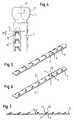
- the bone anchoring element 1has a shaft 2 with a Tip 3 at one end and a head 4 at the other end on.
- the shaft 2is cylindrical and has a A plurality of extending parallel to the shaft axis M Grooves 5, 5 ', which at their tip 3 facing the end are open and at their head 4 facing the end, preferably with a rounding, are closed.
- the profile of the grooves 5is, as can be seen in particular from FIG. 3, dovetail-shaped, but it can also be another form, such as have a T-shape.
- the elongated sheets 6each have a plurality of Barb elements 7 on.
- the barb elements 7are as in particular from Figures 5 to 7 can be seen by Forming substantially trapezoidal cuts 8 in FIG formed the sheets 6, wherein the base 9 of the trapezium of the approach and the bending point for the barb elements 7 in FIG Sheet 6, 6 'is.
- the barb elements 7are arranged so that in the inserted state in the grooves 5, the wider Base 9 is facing the top 3 and the narrower free Ends 10 of the barb elements 7 face the head 4.
- the barb elementsstand 7 by a predetermined angle ⁇ from the surface away, depending on the material used and the dimensions of the barb elements 7 during manufacture is chosen so that given a desired rigidity is.
- the barb elements 7are due to their connection elastic only over the base 9 and point in one of the incisions 8 depressed state a bias on.
- the barb elements 7a sheet 6 respectively relative to the barb elements. 7 an adjacent sheet 6 'in the axial direction on a Helix S arranged around the screw axis M.
- the im significant trapezoidal cuts 8are also how in particular from the enlarged view of FIG. 4 can be seen is at an angle ⁇ to the circumference of the circle U inclined, the slope angle of the helix S equivalent.
- the free ends 10 of the barb elementslie thus on the helix S, so that they are similar to cutting edges forming the tip of a screw thread.
- the tip 3 in a portion adjacent to the shaft 2has a smaller one Diameter on than the shaft 2, so the insertion of the Sheets 6 in the grooves is possible.
- an annular securing element 12is provided, which at its end facing the shaft flush with the Shank 2 closes, so that a pushing out of the sheets. 6 is prevented, and which then with a tapered section tapered towards the tip 3 and flush adjoins this.
- the fuse element 12is fixed to the tip connected, preferably welded.
- the head 4has a spherical segment shape in this embodiment on and has on its side facing away from the shaft one Recess 13 for engagement with a screwing tool.
- the anchoring elementis made of a body-friendly material, especially from a body-friendly metal, such as for example, titanium, or from a body-friendly plastic educated.
- the sheets 6are made of the same material as the shaft is formed or made of a different material, if for the sheets due to the required elastic properties the barb elements 7 another material is needed.
- the anchoring element 1is first pre-assembled, by the prefabricated, with the barb elements 7 provided sheets 6, 6 'are inserted into the grooves 5, 5', and then the fuse element 12 firmly connected to the tip becomes.
- a core hole 14 in FIG the bone 15drilled.
- the diameter of the core holecorresponds essentially the diameter of the shaft 2 or he is slightly larger or smaller.
- the anchoring element 1is pressed into the core hole 14. Because of their elasticity are the barb elements 7 against when pressing or pressed into the incisions 8.
- the anchoring elementcan be due to the sliding movement in contrast to the conventional Screw in very quickly.
- a conventional bone screwIn a conventional bone screw is in addition to Drilling the core hole mostly cutting the bone thread in the bones and always a repeated rotational movement required. Compared to the time to anchor a conventional bone screw is needed, is the time needed for introducing the anchoring element of the invention becomes, due to the sliding movement during insertion considerably smaller without the advantages of a screw thread when positioning or to turn it out.
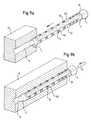
- Figs. 9a) and 9b)show the structure and operation of a modification the first embodiment.
- the sheets 60 with the barbs 70from a body friendly Alloy with shape memory and / or superelastic Properties, for example a titanium nickel alloy, preferably consist of nitinol.
- the sheetsare 60 made so that the barb elements 70 in a state at a predetermined elevated temperature to the outside are formed projecting at a relative to this predetermined elevated temperature lower temperature but in the cutouts 80 are.
- the anchoring element in the core hole 14inserted.
- Fig. 9bis, by means of e.g.
- a heating cartridge Pwhich is in one provided coaxial bore 16 in the interior of the anchoring element is inserted, the anchoring element on the heated at a predetermined temperature, which is characterized by the case occurring phase transition in the crystal structure of the sheets Set up the barb elements 70 and against the wall of the core hole 14. The heating cartridge is then removed again.
- This modified embodimenthas the advantage that a reduced insertion force is required and an adjustment the depth position to some extent by a sliding movement can take place as long as the barb elements 70 not yet press against the wall of the core hole 14.
- This greater elasticityfacilitates the handling and also secures the anchorage in the bone.
- the first embodimenthas the anchoring element that already described in the aforementioned modification, from the free end of the head 4 to the end of the shaft 2 extending coaxial bore 16.
- the coaxial bore 16is about provided in the radial direction of holes 17 with the cutouts 8 of the sheets 6 in conjunction.
- the Anchoring elementIn operation, after insertion and depth positioning of the Anchoring element via the bore 16 and the holes 17th either bone cement for additional anchoring, the emerges through the incisions 8 and hardens, introduced or an active ingredient such as e.g. a drug or a growth-promoting Substance supplied to the surrounding bone area.
- an active ingredientsuch as e.g. a drug or a growth-promoting Substance supplied to the surrounding bone area.
- the radial bores 17need not be in number to the number the incisions 8 correspond, but can be accordingly be less. Furthermore, the central bore 16 also go through the top 3, so that at the end of Tip 3 allows the substance to escape.
- Fig. 11b) and 11a)show by way of example alternative cross-sectional shapes the bone anchoring element with plane or concave side walls.
- the cross-sectional shapeis not on it limited.
- Fig. 12In a further modification shown in Fig. 12 are the radial Holes 17 not circumferentially to the cutouts 8 of the sheets 6 directed towards, but open into the wall sections 18 of the shaft, in which no sheets 6 provided are.
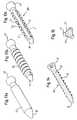
- Figures 13a) to 13c)show manufacturing steps of a Anchoring element 100 according to a second embodiment, and Fig. 14 shows a cross section in the longitudinal direction of the anchoring element according to the second embodiment, which is in Fig. 13c) is shown.
- the Production of the anchoring element 100 according to the second embodimentan element with a shank 20, a tip 30 at one end of the shaft and a head 40 at the opposite End provided.
- a thread 50is cut into the shaft 20.
- a thread 50 in the thread Undercut produced such that, as shown in Fig. 13c) can be seenis, the head 40 facing the partial edge 51 with the tip 30 facing the partial flank 52 forms an angle, which is only a few degrees. This is a certain Elasticity generated.
- FIG. 13a thread 50 in the thread Undercutproduced such that, as shown in Fig. 13c) can be seen is, the head 40 facing the partial edge 51 with the tip 30 facing the partial flank 52 forms an angle, which is only a few degrees. This is a certain Elasticity generated.
- the anchoring element according to this embodimentis, for example from a body-friendly plastic material, e.g. a high molecular weight polyethylene formed. Thereby leaves the easiest way the required elasticity of the barb elements 57 achieve.
- the anchoring element 100in another modification, also has a coaxial bore and bores extending therefrom in the radial direction into the wall for introducing an active substance.
- the barb elementsneed not be trapezoidal, but may also be square, rectangular or otherwise shaped.
- the barb elements of an axial rowcan be in the same Be provided distances in the axial direction, so that at the Place each turn a barb element is present.
- the distances of the barb elements of a seriesvary in the axial direction, but the distance each a whole multiple of a smallest distance of two Barb elements of an axial row. By different Distances may account for different bone densities be and the strain on certain bone structures be reduced.
- the barb elements of a shape memory alloyare formed such that they protrude at body temperature and abut at a lower temperature, eg at room temperature.
- the anchoring elementin which abut the barb elements, pressed into the core hole. After it has reached body temperature, the barb elements rise up.
- a normal metal with a correspondingly high elasticitycan be used.
- a resorbable materialis possible.
- Body-resorbable plastics, eg polylactide (PLLA)are conceivable.
- the tip 3can be formed separately be and be connected to the shaft.
- the Tipare screwed to the shaft 2, the purpose of this at his the tip facing the end has a bore with internal thread and the tip with a screw-in section with External thread.
- the tipcan also be welded to the shaft become or be put with excess.
- Fig. 16shows a first application example in which for the purpose the stiffening of two vertebrae 90, 91 using a Fusion element 92 monoaxial anchoring elements 93, 94 are provided, via which a rod 95 is anchored in the vortex.
- the monoaxial screws 93, 94each have a shaft 96 with them a tip 97, wherein the shaft according to one of the previously described Embodiments of the anchoring element formed is.
- Shaft 96is a receiving part rigidly connected to the shaft 98 provided, in which in a known manner, the rod 95th is inserted and via a fixing element 99, for example secured by a nut which can be screwed onto the receiving part is.
- the training of the Shaft 96 with the made of the shape memory alloy Sheet with barb elementsadvantageous because after the Press into the core hole and before heating the Anchoring element, the anchoring element in the core hole is rotatable and so the receiving part 98 relative to the can be aligned bar to be inserted.
- Fig. 17shows another application example, which is differs from the example of application according to FIG. 16, that instead of the monoaxial anchoring elements polyaxial anchoring elements are provided.
- the polyaxial anchoring elements 93 ', 94'have a shaft 96 with a Tip 97, wherein the shaft 96 according to one of the embodiments the anchoring element according to the invention with the barb elements is trained.
- a head 101is provided, in a receiving part 98 'in unfixed state is held pivotally.
- a rod 95can be inserted, via a pressure piece 102 or (not shown) presses directly on the head 101 and thus fixed the pivotal position of the head relative to the receiving part.
- Fig. 18shows another example of the stiffening two vertebral bones 90, 91 after removal of an intermediate Vortex part via a fusion element 92 'and a Plate 103, via anchoring elements 104, 105 in the vertebrae is anchored.
- the anchoring elements 104, 105have a shank with barb elements according to the invention and a head over which the plate 103 against the vertebral bone is pressed.
- the anchoring elementis also together Can be used with plates used in accident surgery.
- Fig. 19shows a further application example of an intramedullary nail 106, which has a shaft and a tip 107. Adjacent at the top, the shaft has a portion 108 which as in the inventive anchoring element with barbs Is provided.
- the intramedullary nailbecomes a tubular bone introduced and secured by a screw 109.
- Fig. 20shows another embodiment in which the Bone anchoring element together with a plate 110 for Fixation of a bone fracture is used.
- the bone anchoring elementhas a first adjacent to the top 3 Shank portion 111, which includes the barb elements and a second shaft portion adjacent thereto 112 with an opposite end of the tip 3 into the interior extending blind hole 113 with a Inner thread.
- the anchoring element screwed screw 114thintended for connecting the bone anchoring element with the plate 110 is one in the section with the internal thread the anchoring element screwed screw 114th intended. In operation, after generating the core hole in the bone fragments 115, 116 to be fixed, the anchoring element pressed.
- the core holeis from such a length that the portion 111 with the barb elements and the tip 3 of the anchoring element in the one Bone fragment 116 are positionable and the shaft portion 112 with the internal thread in the other bone fragment 115.
- screwing the screw 114 into the hole 113 with the internal threadare due to the barb function of section 111, which is in the one bone fragment 116, the two bone fragments 115 and 116 to each other attracted.
- Other screws 117can be used to fix the Plate be provided.
- FIG. 21is different from that in FIG Fig. 20 shown embodiment of the anchoring element in that instead of the shaft portion 112 with the bore 113 with the internal thread to the section 111 with the barb elements adjacent shaft portion 118 with a External thread is provided, on which a nut 119 screwed is.
- the operationis the same as that described in FIG Embodiment, except that instead of screwing the screw 114 a screwing the nut 119th takes place.
- FIG. 22shows an application example on a hip bone, FIG. Fig. 23 at the rear foot.
Landscapes
- Health & Medical Sciences (AREA)
- Orthopedic Medicine & Surgery (AREA)
- Surgery (AREA)
- Life Sciences & Earth Sciences (AREA)
- Neurology (AREA)
- Engineering & Computer Science (AREA)
- Molecular Biology (AREA)
- Public Health (AREA)
- Heart & Thoracic Surgery (AREA)
- Medical Informatics (AREA)
- Nuclear Medicine, Radiotherapy & Molecular Imaging (AREA)
- Animal Behavior & Ethology (AREA)
- General Health & Medical Sciences (AREA)
- Biomedical Technology (AREA)
- Veterinary Medicine (AREA)
- Chemical & Material Sciences (AREA)
- Combustion & Propulsion (AREA)
- Transportation (AREA)
- Mechanical Engineering (AREA)
- Surgical Instruments (AREA)
Abstract
Translated fromGermanDescription
Translated fromGermanDie Erfindung betrifft ein Knochenverankerungselement.The invention relates to a bone anchoring element.
Eine bekannte Form eines Knochenverankerungselements ist eineKnochenschraube, die einen Schaft mit einem Gewinde zum Einschraubenin einen Knochen aufweist. Das Einbringen in denKnochen erfolgt durch manuelles Einschrauben mittels einesSchraubendrehers, was ein zeitaufwendiger und krafterfordernderVorgang ist. Zudem können beim Einschrauben hohe Druckkräfteauf die Knochenstruktur ausgeübt werden, was in manchenFällen nicht wünschenswert ist. Deshalb ist für bestimmteklinische Anforderungen, insbesondere in der Neurochirurgie,der Wirbelsäulenchirurgie oder der Kinderchirurgie das manuelleEinschrauben von Knochenverankerungselementen weniger geeignet.One known form of bone anchoring element is oneBone screw, which screw a shank with a threadin a bone. The introduction in theBone is done by manual screwing by means of aScrewdrivers, which is a time-consuming and force-demandingProcess is. In addition, when screwing high pressure forcesbe exercised on the bone structure, resulting in someCases is not desirable. That is why for certainclinical requirements, especially in neurosurgery,Spinal surgery or pediatric surgery manualScrewing in bone anchoring elements less suitable.
Aus der EP 0 714 643 A1 ist ein Knochenverankerungselement miteinem Schaft und einem Knochengewinde bekannt, wobei auf denGewindeflanken des Knochengewindes eine Mikrotextur vorgesehen ist, die Elemente aufweist, die widerhakenähnliche Funktionenhaben. Dadurch ist das Einschrauben leicht möglich, das Herausschraubenjedoch behindert. In einem weiteren Beispiel sindstachelartige Spitzen als Mikrorauhigkeit an einem Knochenstiftvorgesehen.From EP 0 714 643 A1 a bone anchoring element witha shaft and a bone thread, wherein on theThread flanks of the bone thread provided a microtexturethat has barb-like featuresto have. This screwing is easily possible, unscrewingbut handicapped. In another examplespiny tips as a microroughness on a bone pinintended.
Aus der DE 198 01 219 A1 ist ein Knochennagel bekannt, der anseinem Schaft eine Mehrzahl von Vorsprüngen aufweist, die eineinfachen Eintreiben des Nagels ermöglichen, jedoch ein Herausziehendes Nagels behindern.From DE 198 01 219 A1 discloses a bone nail is known to thehis shaft has a plurality of projections, the oneallow easy driving of the nail, but a pull outof the nail.
Es ist Aufgabe der vorliegenden Erfindung, ein Knochenverankerungselementbereitzustellen, das schneller, einfacher und mitweniger Kraftaufwand in den Knochen einzubringen ist, keineschädigenden Kräfte auf den Knochen ausübt, einen sicherenHalt gewährleistet und dennoch im Sinne einer Schraube tiefereingebracht bzw. entfernt werden kann.It is an object of the present invention, a bone anchoring elementto provide that faster, easier and withless effort is required in the bones, nonedamaging forces on the bones, a safeHalt guaranteed and yet deeper in the sense of a screwcan be introduced or removed.
Die Aufgabe wird gelöst durch ein Knochenverankerungselementnach Patentanspruch 1. Weiterbildungen der Erfindung sind inden Unteransprüchen angegeben.The problem is solved by a bone anchoring elementaccording to
Das Knochenverankerungselement weist den Vorteil auf, daß eineschnelle und sichere Verankerung durch Eindrücken des Verankerungselementsin ein vorgebohrtes Kernloch im Knochen möglichist. Durch die Anordnung der Widerhakenelemente auf einerSchraubenlinie ist eine gewindeähnliche Funktion gegeben, dieeine zusätzliche Tiefenpositionierung durch eine Einschraubbewegungähnlich der von Knochenschrauben erlaubt. Ferner istdurch die Widerhakenelemente eine Sicherheit gegen Herausziehenoder Lockerung des Knochenverankerungselements gegeben.Das eventuelle Entfernen des Knochenverankerungselements erfolgtwie bei einer Schraube durch Rückdrehung.The bone anchoring element has the advantage that afast and secure anchoring by pressing in the anchoring elementinto a predrilled core hole in the bone possibleis. By the arrangement of the barb elements on oneHelix is given a thread-like function thatan additional depth positioning by a screwingsimilar to that allowed by bone screws. Further isby the barb elements security against pulling outor loosening of the bone anchoring element.The eventual removal of the bone anchoring element takes placeas with a screw by reverse rotation.
Weitere Merkmale und Zweckmäßigkeiten der Erfindung ergebensich aus der Beschreibung von Ausführungsbeispielen anhand derFiguren. Von den Figuren zeigen:
- Fig. 1
- eine perspektivische Ansicht eines Knochenverankerungselementsnach einer ersten Ausführungsform;
- Fig. 2
- eine perspektivische Explosionsdarstellung des Knochenverankerungselementsvon Fig. 1;
- Fig. 3
- eine Schnittansicht des Knochenverankerungselementsvon Fig. 1 entlang der Linie III-III;
- Fig. 4
- eine vergrößerte perspektivische Ansicht eines Detailsdes Knochenverankerungselements von Fig. 1;
- Fig. 5
- eine perspektivische Ansicht eines Elements des Knochenverankerungselementsnach den
Figuren 1 bis 4 ineinem ersten Zustand; - Fig. 6
- eine perspektivische Ansicht des Elements gemäß Fig.5 in einem zweiten Zustand;
- Fig. 7
- eine Schnittansicht des Elements von Fig. 6 gemäßLinie II-II in Fig. 6;
- Fig. 8a)
- eine schematische Darstellung, die das Einbringendes Knochenverankerungselements nach den
Figuren 1bis 7 in einem ersten Schritt zeigt; - Fig. 8b)
- eine schematische Darstellung, die das Einbringeneines Knochenverankerungselements nach einer abgewandeltenAusführungsform zeigt;
- Fig. 9a)
- eine schematische Darstellung, die das Einbringeneiner abgewandelten Ausführungsform des Knochenverankerungselementsnach Fig. 1 bis 7 in einem erstenSchritt zeigt;
- Fig. 9b)
- eine schematische Darstellung, die das Einbringender abgewandelten Ausführungsform in einem zweitenSchritt zeigt;
- Fig. 10
- eine perspektivische Ansicht eines Knochenverankerungselementsnach einer weiteren Abwandlung derersten Ausführungsform;
- Fig. 11a)
- eine Schnittansicht des Knochenverankerungselementsnach Fig. 10 entlang der Linie IV-IV;
- Fig. 11b), 11c)
- alternative Ausführungsformen für den Querschnittdes Knochenverankerungselements;
- Fig. 12
- eine perspektivische Ansicht eines Knochenverankerungselementsnach einer weiteren Abwandlung der erstenAusführungsform;
- Fig. 13a) bis 13c)
- Schritte der Herstellung eines Knochenverankerungselementsnach einer zweiten Ausführungsform;
- Fig. 14
- eine Ansicht im Längsschnitt durch das Knochenverankerungselementnach dem letzten Herstellungsschrittgemäß Fig. 13c);
- Fig. 15
- eine Querschnittsansicht durch den Schaft des Knochenverankerungselementsgemäß Fig. 13c) der zweitenAusführungsform;
- Fig. 16bis Fig. 23
- Beispiele für die Verwendung des Knochenverankerungselements.
- Fig. 1
- a perspective view of a bone anchoring element according to a first embodiment;
- Fig. 2
- an exploded perspective view of the bone anchoring element of Fig. 1;
- Fig. 3
- a sectional view of the bone anchoring element of Figure 1 along the line III-III.
- Fig. 4
- an enlarged perspective view of a detail of the bone anchoring element of Fig. 1;
- Fig. 5
- a perspective view of an element of the bone anchoring element of Figures 1 to 4 in a first state;
- Fig. 6
- a perspective view of the element of Figure 5 in a second state.
- Fig. 7
- a sectional view of the element of Figure 6 taken along line II-II in Fig. 6 .;
- Fig. 8a)
- a schematic representation showing the introduction of the bone anchoring element according to Figures 1 to 7 in a first step;
- Fig. 8b)
- a schematic representation showing the introduction of a bone anchoring element according to a modified embodiment;
- Fig. 9a)
- a schematic representation showing the introduction of a modified embodiment of the bone anchoring element of Figure 1 to 7 in a first step.
- Fig. 9b)
- a schematic representation showing the introduction of the modified embodiment in a second step;
- Fig. 10
- a perspective view of a bone anchoring element according to another modification of the first embodiment;
- Fig. 11a)
- a sectional view of the bone anchoring element of Figure 10 along the line IV-IV ..;
- Fig. 11b), 11c)
- alternative embodiments for the cross section of the bone anchoring element;
- Fig. 12
- a perspective view of a bone anchoring element according to another modification of the first embodiment;
- Fig. 13a) to 13c)
- Steps of manufacturing a bone anchoring element according to a second embodiment;
- Fig. 14
- a view in longitudinal section through the bone anchoring element after the last manufacturing step of FIG. 13c);
- Fig. 15
- a cross-sectional view through the shaft of the bone anchoring element according to FIG. 13c) of the second embodiment;
- Fig. 16 to Fig. 23
- Examples of the use of the bone anchoring element.
Im folgenden wird mit Bezug auf die Figuren 1 bis 7 ein Knochenverankerungselementnach einer ersten Ausführungsform beschrieben.In the following, with reference to Figures 1 to 7, a bone anchoring elementdescribed according to a first embodiment.
Das Knochenverankerungselement 1 weist einen Schaft 2 mit einerSpitze 3 an einem Ende und einem Kopf 4 an dem anderen Endeauf. Der Schaft 2 ist zylindrisch ausgebildet und weist eineMehrzahl von sich parallel zur Schaftachse M erstreckendeNuten 5, 5' auf, die an ihrem der Spitze 3 zugewandten Endeoffen sind und an ihrem dem Kopf 4 zugewandten Ende, bevorzugtmit einer Rundung, geschlossen sind. Das Profil der Nuten 5ist, wie insbesondere aus Fig. 3 ersichtlich ist, schwalbenschwanzförmig,es kann aber auch eine andere Form, wie z.B.eine T-Form aufweisen. In dem dargestellten Beispiel sind dreiin Umfangsrichtung des Schafts 2 gleichmäßig beabstandete Nuten5 vorgesehen, es können jedoch auch wenigstens zwei odermehr als drei Nuten vorgesehen sein.The
In die Nuten 5 sind längliche Bleche 6, 6' eingesetzt, derenQuerschnitt dem der Nuten 5 angepaßt ist, so daß sie in dieNuten 5, 5' einschiebbar sind und darin paßförmig gehalten sind. Die länglichen Bleche 6 weisen jeweils eine Mehrzahl vonWiderhakenelementen 7 auf. Die Widerhakenelemente 7 sind, wieinsbesondere aus den Figuren 5 bis 7 ersichtlich ist, durchBilden von im wesentlichen trapezförmigen Einschnitten 8 inden Blechen 6 gebildet, wobei die Basis 9 des Trapezes der Ansatzund die Biegungsstelle für die Widerhakenelemente 7 imBlech 6, 6' ist. Die Widerhakenelemente 7 sind so angeordnet,daß in dem in die Nuten 5 eingesetzten Zustand die breitereBasis 9 der Spitze 3 zugewandt ist und die schmäleren freienEnden 10 der Widerhakenelemente 7 dem Kopf 4 zugewandt sind.In the
Wie aus den Figuren 5 bis 7 ersichtlich ist, stehen die Widerhakenelemente7 um einen vorbestimmten Winkel γ von der Oberflächeweg, der in Abhängigkeit von dem verwendeten Materialund den Abmessungen der Widerhakenelemente 7 bei der Herstellungso gewählt wird, daß eine gewünschte Steifigkeit gegebenist. Die Widerhakenelemente 7 sind aufgrund ihrer Anbindungnur über die Basis 9 elastisch und weisen in einem in die Einschnitte8 eingedrückten Zustand eine Vorspannung auf.As can be seen from FIGS. 5 to 7, the barb elements stand7 by a predetermined angle γ from the surfaceaway, depending on the material usedand the dimensions of the
Wie aus Fig. 1 ersichtlich ist, sind die Widerhakenelemente 7eines Bleches 6 jeweils relativ zu den Widerhakenelementen 7eines benachbarten Bleches 6' in axialer Richtung auf einerSchraubenlinie S um die Schraubenachse M angeordnet. Die imwesentlichen trapezförmigen Einschnitte 8 sind ferner, wieinsbesondere aus der vergrößerten Darstellung gemäß Fig. 4 ersichtlichist, unter einem Winkel α gegen die KreisumfangslinieU geneigt, der dem Steigungswinkel der Schraubenlinie Sentspricht. Die freien Enden 10 der Widerhakenelemente liegensomit auf der Schraubenlinie S, so daß sie Schneidkanten ähnlichder Spitze eines Schraubengewindes bilden.As can be seen from FIG. 1, the barb elements 7a
Wie ferner aus den Figuren 1 und 2 ersichtlich ist, ist beidem gezeigten Ausführungsbeispiel in einem kopfnahen Bereichin jeder Windung der imaginären Schraubenlinie S ein Widerhakenelement7 vorgesehen, und in einem Bereich angrenzend andie Spitze 3 ist in jeder zweiten Windung ein Widerhakenelementvorgesehen.As further seen in Figures 1 and 2, is atthe embodiment shown in a near-head areain each turn of the imaginary helix S, a
Wie aus Fig. 2 ersichtlich ist, weist ferner die Spitze 3 ineinem an den Schaft 2 angrenzenden Abschnitt einen kleinerenDurchmesser auf als der Schaft 2, damit das Einschieben derBleche 6 in die Nuten möglich ist. Im montierten Zustand derBleche 6, in dem diese in die Nuten 5 eingeschoben sind, istferner ein ringförmiges Sicherungselement 12 vorgesehen, welchesan seinem dem Schaft zugewandten Ende bündig mit demSchaft 2 abschließt, so daß ein Herausschieben der Bleche 6verhindert wird, und welches sich dann mit einem kegeligen Abschnittzur Spitze 3 hin verjüngt und bündig an diese anschließt.Das Sicherungselement 12 ist fest mit der Spitzeverbunden, bevorzugt angeschweißt.As is apparent from Fig. 2, furthermore, the
Der Kopf 4 weist in dieser Ausführungsform eine Kugelsegmentformauf und hat an seiner dem Schaft abgewandten Seite eineAusnehmung 13 zum Eingreifen mit einem Eindrehwerkzeug.The head 4 has a spherical segment shape in this embodimenton and has on its side facing away from the shaft one
Das Verankerungselement ist aus einem körperfreundlichen Material,insbesondere aus einem körperfreundlichen Metall, wiebeispielsweise Titan, oder aus einem körperfreundlichen Kunststoffgebildet. Die Bleche 6 sind aus demselben Material wieder Schaft gebildet oder aus einem anderen Material, wenn fürdie Bleche aufgrund der geforderten elastischen Eigenschaftender Widerhakenelemente 7 ein anderes Material benötigt wird.The anchoring element is made of a body-friendly material,especially from a body-friendly metal, such asfor example, titanium, or from a body-friendly plasticeducated. The
Im Betrieb wird das Verankerungselement 1 zunächst vormontiert,indem die vorgefertigten, mit den Widerhakenelementen 7versehenen Bleche 6, 6' in die Nuten 5, 5' eingeführt werden,und dann das Sicherungselement 12 fest mit der Spitze verbundenwird. In der Anwendung wird zunächst, wie schematisch ausden Figuren 8a) und 8b) ersichtlich ist, ein Kernloch 14 inden Knochen 15 gebohrt. Der Durchmesser des Kernlochs entsprichtim wesentlichen dem Durchmesser des Schafts 2 oder erist geringfügig größer oder kleiner. Anschließend wird, wieinsbesondere aus Fig. 8a) ersichtlich ist, das Verankerungselement1 in das Kernloch 14 eingedrückt. Aufgrund ihrer Elastizitätwerden die Widerhakenelemente 7 beim Eindrücken gegenbzw. in die Einschnitte 8 gepreßt. Das Verankerungselementläßt sich durch die Gleitbewegung im Unterschied zum herkömmlichenEinschrauben sehr schnell einführen.In operation, the anchoring
Im eingeführten Zustand stellen sich die unter Vorspannungstehenden Widerhakenelemente 7, wie aus Fig. 8b) ersichtlichist, auf und drücken mit ihrer Schneidkante 10 nach außen gegendie Wandung des Kernlochs 14. Durch die Widerhakenwirkungwird ein Herausziehen verhindert.In the inserted state, the under biasstanding
Zum korrekten Positionieren des Verankerungselements in derTiefe im Kernloch 14 bzw. der Stellung des Kopfs wird es durchAngreifen mit dem Eindrehwerkzeug am Kopf 4 wie eine Schraubedurch eine Drehbewegung weiter in das Kernloch 14 hinein oderaus diesem herausgeschraubt. Die Schneidkanten 10 der Widerhakenelemente,die auf der Schraubenlinie S liegen, wirken dabeiwie die Spitze eines Gewindes. Ein eventuelles Entfernen desKnochenverankerungselements erfolgt wie bei einer Schraubedurch Rückdrehung.For correct positioning of the anchoring element in theDepth in the
Bei einer herkömmlichen Knochenschraube ist zusätzlich zumBohren des Kernloches meistens das Schneiden des Knochengewindesin den Knochen und immer eine wiederholte Drehbewegung erforderlich.Im Vergleich zur Zeit, die zum Verankern einerherkömmlichen Knochenschraube benötigt wird, ist die Zeit, diezum Einbringen des Verankerungselements der Erfindung benötigtwird, aufgrund der Gleitbewegung beim Einschieben erheblichkleiner ohne auf die Vorteile eines Schraubengewindes beim Positionierenoder Herausdrehen zu verzichten.In a conventional bone screw is in addition toDrilling the core hole mostly cutting the bone threadin the bones and always a repeated rotational movement required.Compared to the time to anchor aconventional bone screw is needed, is the timeneeded for introducing the anchoring element of the inventionbecomes, due to the sliding movement during insertion considerablysmaller without the advantages of a screw thread when positioningor to turn it out.
Fig. 9a) und 9b) zeigen den Aufbau und den Betrieb einer Abwandlungder ersten Ausführungsform.Figs. 9a) and 9b) show the structure and operation of a modificationthe first embodiment.
Diese unterscheidet sich von der ersten Ausführungsform dadurch,daß die Bleche 60 mit den Widerhaken 70 aus einer körperfreundlichenLegierung mit Formgedächtnis- und/oder superelastischenEigenschaften, beispielsweise einer Titannickellegierung,bevorzugt aus Nitinol bestehen. Die Bleche 60 werdendabei so gefertigt, daß die Widerhakenelemente 70 in einem Zustandmit einer vorbestimmten erhöhten Temperatur nach außenabstehend geformt sind, bei einer relativ zu dieser vorbestimmtenerhöhten Temperatur niedrigeren Temperatur aber inden Ausschnitten 80 liegen. In diesem Zustand wird, wie inFig. 9a) gezeigt ist, das Verankerungselement in das Kernloch14 eingeschoben. Nach dem Einschieben wird wie in Fig. 9b gezeigtist, mittels z.B. einer Heizpatrone P, die in eine dafürvorgesehene koaxiale Bohrung 16 im Inneren des Verankerungselementseingeschoben wird, das Verankerungselement auf dievorbestimmte Temperatur erwärmt, wobei sich durch den dabeistattfindenden Phasenübergang in der Kristallstruktur der Blechedie Widerhakenelemente 70 aufstellen und gegen die Wanddes Kernlochs 14 drücken. Die Heizpatrone wird anschließendwieder entfernt.This differs from the first embodiment in thatthat the
Diese abgewandelte Ausführungsform hat den Vorteil, daß einereduzierte Einpreßkraft erforderlich ist und eine Justierungder Tiefenposition in gewissem Umfang durch eine Gleitbewegungerfolgen kann, solange die Widerhakenelemente 70 noch nichtgegen die Wand des Kernlochs 14 drücken. Bei Vorliegen von Superelastizitätweisen die Widerhakenelemente 70 aufgrund derSuperelastizität der Legierung eine etwa zehnprozentige Dehnungauf, gegenüber einer etwa einprozentigen Dehnung vonherkömmlichen Metallen. Diese größere Elastizität erleichtertdie Handhabung und sichert zusätzlich die Verankerung im Knochen.This modified embodiment has the advantage that areduced insertion force is required and an adjustmentthe depth position to some extent by a sliding movementcan take place as long as the
In einer weiteren in den Figuren 10 und 11a) gezeigten Abwandlungder ersten Ausführungsform weist das Verankerungselementdie bereits bei der zuvor genannten Abwandlung beschriebene,sich vom freien Ende des Kopfs 4 bis zum Ende des Schafts 2erstreckende koaxiale Bohrung 16 auf. Die koaxiale Bohrung 16steht über in radial verlaufender Richtung vorgesehene Bohrungen17 mit den Ausschnitten 8 der Bleche 6 in Verbindung.In a further modification shown in FIGS. 10 and 11a)The first embodiment has the anchoring elementthat already described in the aforementioned modification,from the free end of the head 4 to the end of the
Im Betrieb wird nach dem Einführen und Tiefenpositionieren desVerankerungselements über die Bohrung 16 und die Bohrungen 17entweder Knochenzement zur zusätzlichen Verankerung, derdurch die Einschnitte 8 austritt und aushärtet, eingeführt oderein Wirkstoff wie z.B. ein Arzneimittel oder eine wachstumsförderndeSubstanz dem umliegenden Knochenbereich zugeführt.In operation, after insertion and depth positioning of theAnchoring element via the
Die radialen Bohrungen 17 müssen in ihrer Anzahl nicht der Anzahlder Einschnitte 8 entsprechen, sondern können entsprechendweniger sein. Ferner kann die zentrale Bohrung 16 auch durch die Spitze 3 hindurchgehen, so daß auch am Ende derSpitze 3 ein Austritt der Substanz ermöglicht wird.The radial bores 17 need not be in number to the numberthe
Fig. 11b) und 11a) zeigen beispielhaft alternative Querschnittsformendes Knochenverankerungselements mit ebenen oderkonkaven Seitenwänden. Die Querschnittsform ist nicht daraufbeschränkt.Fig. 11b) and 11a) show by way of example alternative cross-sectional shapesthe bone anchoring element with plane orconcave side walls. The cross-sectional shape is not on itlimited.
In einer in Fig. 12 gezeigten weiteren Abwandlung sind die radialenBohrungen 17 nicht in Umfangsrichtung zu den Ausschnitten8 der Bleche 6 hin gerichtet, sondern münden in die Wandabschnitte18 des Schafts, in denen keine Bleche 6 vorgesehensind.In a further modification shown in Fig. 12 are the
Die Figuren 13a) bis 13c) zeigen Herstellungsschritte einesVerankerungselements 100 nach einer zweiten Ausführungsform,und Fig. 14 zeigt einen Querschnitt in Längsrichtung des Verankerungselementsnach der zweiten Ausführungsform, welches inFig. 13c) gezeigt ist.Figures 13a) to 13c) show manufacturing steps of a
Wie in Fig. 13a) ersichtlich ist, wird im ersten Schritt derHerstellung des Verankerungselements 100 nach der zweiten Ausführungsformein Element mit einem Schaft 20, einer Spitze 30an einem Ende des Schaftes und einem Kopf 40 am gegenüberliegendenEnde bereitgestellt. In dem in Fig. 13b) gezeigtenzweiten Schritt wird in den Schaft 20 ein Gewinde 50 geschnitten.In einem nächsten Schritt wird in dem Gewinde 50 eineHinterschneidung derart erzeugt, daß, wie aus Fig. 13c) ersichtlichist, die dem Kopf 40 zugewandte Teilflanke 51 mitder der Spitze 30 zugewandten Teilflanke 52 einen Winkel einschließt,der nur wenige Grad beträgt. Dadurch ist eine gewisseElastizität erzeugt. Wie aus Fig. 13c) ersichtlich ist,werden anschließend in Längsrichtung des Schafts Abschnitte 53 herausgefräst, die vorzugsweise zur Mittelachse des Schaftshin konkav ausgebildet sind und die sich über die gesamteSchaftlänge erstrecken. Es werden wenigstens zwei, bevorzugtaber mehrere gleichmäßig in Umfangsrichtung beabstandete Abschnitte53 gebildet. Dadurch entstehen mit den verbleibendenGewindeteilen mit Hinterschneidung Widerhakenelemente 57, ähnlichden Widerhakenelementen 7 der ersten Ausführungsform.As can be seen in FIG. 13a), in the first step, theProduction of the
Das Verankerungselement nach dieser Ausführungsform ist beispielsweiseaus einem körperfreundlichen Kunststoffmaterial,z.B. einem hochmolekularem Polyethylen gebildet. Dadurch läßtsich am einfachsten die erforderliche Elastizität der Widerhakenelemente57 erzielen.The anchoring element according to this embodiment is, for examplefrom a body-friendly plastic material,e.g. a high molecular weight polyethylene formed. Thereby leavesthe easiest way the required elasticity of the
Weitere Abwandlungen der beschriebenen Ausführungsformen sindmöglich und Elemente der einzelnen Ausführungsformen und Abwandlungenderselben können miteinander kombiniert werden.Further modifications of the described embodiments arepossible and elements of the individual embodiments and modificationsthey can be combined with each other.
Beispielsweise hat in einer weiteren Abwandlung das Verankerungselement100 nach der zweiten Ausführungsform ebenfallseine koaxiale Bohrung und sich davon in radialer Richtung indie Wand erstreckende Bohrungen zum Einführen einer Wirksubstanz.
Die Widerhakenelemente müssen nicht trapezförmig sein, sondernkönnen auch quadratisch, rechteckig oder anderweitig geformtsein.For example, in another modification, the anchoring
The barb elements need not be trapezoidal, but may also be square, rectangular or otherwise shaped.
Anders als bei dem in Fig. 1 gezeigten Ausführungsbeispielkönnen die Widerhakenelemente einer axialen Reihe in gleichenAbständen in axialer Richtung vorgesehen sein, so daß an derStelle jeder Windung ein Widerhakenelement vorhanden ist. Alternativkönnen die Abstände der Widerhakenelemente einer Reihein axialer Richtung variieren, wobei aber der Abstand jeweils ein ganzes Vielfaches eines kleinsten Abstands zweierWiderhakenelemente einer axialen Reihe ist. Durch unterschiedlicheAbstände können unterschiedliche Knochendichten berücksichtigtwerden und die Belastung auf bestimmte Knochenstrukturenreduziert werden.Unlike the embodiment shown in Fig. 1For example, the barb elements of an axial row can be in the sameBe provided distances in the axial direction, so that at thePlace each turn a barb element is present. alternativecan the distances of the barb elements of a seriesvary in the axial direction, but the distance eacha whole multiple of a smallest distance of twoBarb elements of an axial row. By differentDistances may account for different bone densitiesbe and the strain on certain bone structuresbe reduced.
In einer weiteren Abwandlung sind die Widerhakenelemente auseiner Formgedächtnislegierung derart gebildet, daß sie beiKörpertemperatur abstehen und bei einer niedrigeren Temperatur,z.B. bei Raumtemperatur, anliegen.
Im Betrieb wird das Verankerungselement, bei dem die Widerhakenelementeanliegen, in die Kernlochbohrung eingedrückt.Nachdem es die Körpertemperatur angenommen hat, stellen sichdie Widerhakenelemente auf.In a further modification, the barb elements of a shape memory alloy are formed such that they protrude at body temperature and abut at a lower temperature, eg at room temperature.
In operation, the anchoring element, in which abut the barb elements, pressed into the core hole. After it has reached body temperature, the barb elements rise up.
Als Material für das Verankerungselement nach der ersten Ausführungsform,bzw. der Bleche mit den Widerhakenelementen, oderder einstückig ausgebildeten Schraube nach der zweitenAusführungsform kann auch ein Normalmetall mit entsprechendhoher Elastizität verwendet werden.
Weiterhin ist die Verwendung eines resorbierbaren Materialsmöglich. Körperresorbierbare Kunststoffe, z.B. Polylactid(PLLA) sind denkbar.As a material for the anchoring element according to the first embodiment, or the sheets with the barb elements, or the integrally formed screw according to the second embodiment, a normal metal with a correspondingly high elasticity can be used.
Furthermore, the use of a resorbable material is possible. Body-resorbable plastics, eg polylactide (PLLA) are conceivable.
In einer weiteren Abwandlung kann die Spitze 3 getrennt ausgebildetsein und mit dem Schaft verbindbar sein. Z.B. kann dieSpitze an den Schaft 2 geschraubt werden, der hierzu an seinemder Spitze zugewandten Ende eine Bohrung mit Innengewinde aufweistund die Spitze einen darin einschraubbaren Abschnitt mitAußengewinde. Die Spitze kann auch an den Schaft geschweißtwerden oder mit Übermaß gesteckt werden.In a further modification, the
Fig. 16 zeigt ein erstes Anwendungsbeispiel, bei dem zum Zweckeder Versteifung zweier Wirbel 90, 91 unter Verwendung einesFusionselements 92 Monoaxialverankerungselemente 93, 94vorgesehen sind, über die ein Stab 95 im Wirbel verankert ist.Die Monoaxialschrauben 93, 94 weisen jede einen Schaft 96 miteiner Spitze 97 auf, wobei der Schaft nach einer der zuvor beschriebenenAusführungsformen des Verankerungselements ausgebildetist. An dem der Spitze 97 gegenüberliegenden Ende desSchafts 96 ist ein mit dem Schaft starr verbundenes Aufnahmeteil98 vorgesehen, in welches in bekannter Weise der Stab 95eingelegt ist und über ein Fixierelement 99, beispielsweiseüber eine auf das Aufnahmeteil aufschraubbare Mutter, gesichertist. Bei der Monoaxialschraube ist die Ausbildung desSchafts 96 mit den aus der Formgedächtnislegierung gefertigtenBlechen mit den Widerhakenelementen vorteilhaft, da nach demEindrücken in die Kernlochbohrung und vor dem Erwärmen desVerankerungselements das Verankerungselement in der Kernlochbohrungdrehbar ist und so das Aufnahmeteil 98 relativ zu demeinzulegenden Stab ausrichtbar ist.Fig. 16 shows a first application example in which for the purposethe stiffening of two
Fig. 17 zeigt ein weiteres Anwendungsbeispiel, welches sichvon dem Anwendungsbeispiel gemäß Fig. 16 dadurch unterscheidet,daß anstelle der Monoaxial-Verankerungselemente Polyaxial-Verankerungselementevorgesehen sind. Die Polyaxial-Verankerungselemente93', 94' weisen einen Schaft 96 mit einerSpitze 97 auf, wobei der Schaft 96 nach einer der Ausführungsformendes erfindungsgemäßen Verankerungselements mit den Widerhakenelementenausgebildet ist. An dem der Spitze 97 gegenüberliegendenEnde des Schafts 96 ist ein Kopf 101 vorgesehen,der in einem Aufnahmeteil 98' in nichtfixiertem Zustandschwenkbar gehalten ist. In das Aufnahmeteil ist in bekannterWeise ein Stab 95 einlegbar, der über ein Druckstück 102 oder(nicht dargestellt) direkt auf den Kopf 101 drückt und somit die Schwenkstellung des Kopfes relativ zu dem Aufnahmeteil fixiert.Fig. 17 shows another application example, which isdiffers from the example of application according to FIG. 16,that instead of the monoaxial anchoring elements polyaxial anchoring elementsare provided. The polyaxial anchoring elements93 ', 94' have a
Fig. 18 zeigt als weiteres Anwendungsbeispiel die Versteifungzweier Wirbelknochen 90, 91 nach Entfernung eines dazwischenliegendenWirbelteiles über ein Fusionselement 92' und einePlatte 103, die über Verankerungselemente 104, 105 in den Wirbelnverankert ist. Die Verankerungselemente 104, 105 weiseneinen Schaft mit Widerhakenelementen gemäß der Erfindung aufund einen Kopf, über den die Platte 103 gegen den Wirbelknochengedrückt wird. Das Verankerungselement ist auch zusammenmit in der Unfallchirurgie verwendeten Platten einsetzbar.Fig. 18 shows another example of the stiffeningtwo
Fig. 19 zeigt als weiteres Anwendungsbeispiel einen Marknagel106, der einen Schaft und eine Spitze 107 aufweist. Angrenzendan die Spitze weist der Schaft einen Abschnitt 108 auf, derwie bei dem erfindungsgemäßen Verankerungselement mit Widerhakenausgestattet ist. Der Marknagel wird in einen Röhrenknocheneingeführt und über eine Schraube 109 gesichert.Fig. 19 shows a further application example of an
Fig. 20 zeigt ein weiteres Ausführungsbeispiel, bei dem dasKnochenverankerungselement zusammen mit einer Platte 110 zurFixierung einer Knochenfraktur eingesetzt wird. Das Knochenverankerungselementweist einen ersten an die Spitze 3 angrenzendenSchaftabschnitt 111 auf, der die Widerhakenelemente beinhaltetund angrenzend daran einen zweiten Schaftabschnitt112 mit einer von dem der Spitze 3 gegenüberliegenden Endesich ins Innere erstreckende Sacklochbohrung 113 mit einemInnengewinde. Zum Verbinden des Knochenverankerungselementsmit der Platte 110 ist eine in den Abschnitt mit dem Innengewindedes Verankerungselements einschraubbare Schraube 114vorgesehen. Im Betrieb wird nach Erzeugen der Kernlochbohrungin den zu fixierenden Knochenfragmenten 115, 116 das Verankerungselement eingepreßt. Die Kernlochbohrung ist dabei vonsolch einer Länge, daß der Abschnitt 111 mit den Widerhakenelementenund die Spitze 3 des Verankerungselements in dem einenKnochenfragment 116 positionierbar sind und der Schaftabschnitt112 mit dem Innengewinde in dem anderen Knochenfragment115. Beim Einschrauben der Schraube 114 in die Bohrung113 mit dem Innengewinde werden aufgrund der Widerhakenfunktiondes Abschnitts 111, der in dem einen Knochenfragment116 liegt, die beiden Knochenfragmente 115 und 116 zueinanderhingezogen. Weitere Schrauben 117 können zum Fixieren derPlatte vorgesehen sein.Fig. 20 shows another embodiment in which theBone anchoring element together with a
Das in Fig. 21 gezeigte Beispiel unterscheidet sich von dem inFig. 20 gezeigten Ausführungsbeispiel des Verankerungselementsdadurch, daß anstelle des Schaftabschnitts 112 mit der Bohrung113 mit dem Innengewinde ein an den Abschnitt 111 mit den Widerhakenelementenangrenzender Schaftabschnitt 118 mit einemAußengewinde vorgesehen ist, auf das eine Mutter 119 aufschraubbarist. Der Betrieb erfolgt wie bei dem in Fig. 20 beschriebenenAusführungsbeispiel, nur daß anstelle des Einschraubensder Schraube 114 ein Aufschrauben der Mutter 119stattfindet.The example shown in FIG. 21 is different from that in FIGFig. 20 shown embodiment of the anchoring elementin that instead of the
Fig. 22 zeigt ein Anwendungsbeispiel an einem Hüftknochen,Fig. 23 am Rückfuß.FIG. 22 shows an application example on a hip bone, FIG.Fig. 23 at the rear foot.
Claims (20)
Translated fromGermandadurch gekennzeichnet, daß der Schaft einen Abschnitt miteiner Mehrzahl von in einer Schraubenlinie (S) um die Schaftachse(M) angeordneten Widerhakenelementen (7; 70; 57) aufweist.Bone anchoring element having a shaft (2; 20) for anchoring in a bone (15),
characterized in that the shaft has a portion with a plurality of barbed elements (7; 70; 57) arranged in a helical line (S) about the shaft axis (M).
Applications Claiming Priority (4)
| Application Number | Priority Date | Filing Date | Title |
|---|---|---|---|
| US54751704P | 2004-02-24 | 2004-02-24 | |
| US547517P | 2004-02-24 | ||
| DE102004009429ADE102004009429A1 (en) | 2004-02-24 | 2004-02-24 | Bone anchoring element |
| DE102004009429 | 2004-02-24 |
Publications (2)
| Publication Number | Publication Date |
|---|---|
| EP1568329A1true EP1568329A1 (en) | 2005-08-31 |
| EP1568329B1 EP1568329B1 (en) | 2007-06-20 |
Family
ID=34751392
Family Applications (1)
| Application Number | Title | Priority Date | Filing Date |
|---|---|---|---|
| EP05002783AExpired - LifetimeEP1568329B1 (en) | 2004-02-24 | 2005-02-10 | Bone-anchoring element |
Country Status (5)
| Country | Link |
|---|---|
| US (4) | US9326804B2 (en) |
| EP (1) | EP1568329B1 (en) |
| JP (1) | JP4395454B2 (en) |
| KR (1) | KR100794735B1 (en) |
| DE (2) | DE102004009429A1 (en) |
Cited By (19)
| Publication number | Priority date | Publication date | Assignee | Title |
|---|---|---|---|---|
| EP1870047A1 (en)* | 2006-06-22 | 2007-12-26 | Textile Hi-Tec (T.H.T.) | Bone attaching pin |
| EP1931287A4 (en)* | 2005-10-06 | 2011-04-20 | Amei Technologies Inc | IMPLANT FOR BONE ALIGNMENT AND METHOD OF USE |
| CN102958462A (en)* | 2010-05-13 | 2013-03-06 | 斯恩蒂斯有限公司 | Bone screw assembly and instruments for implantation of the same |
| CN103654934A (en)* | 2012-08-30 | 2014-03-26 | 上海微创骨科医疗科技有限公司 | Combined type locking screw applied to bone plate and bone plate system comprising same |
| AU2013200038B2 (en)* | 2005-10-06 | 2015-03-05 | Orthofix S.R.L. | Bone alignment implant and method of use |
| CN105581836A (en)* | 2014-11-06 | 2016-05-18 | 爱派司生技股份有限公司 | Bone screw facilitating cable penetration |
| US10231768B2 (en) | 2003-05-30 | 2019-03-19 | DePuy Synthes Products, Inc. | Methods for implanting bone plates |
| US10335211B2 (en) | 2004-01-26 | 2019-07-02 | DePuy Synthes Products, Inc. | Highly-versatile variable-angle bone plate system |
| US10342586B2 (en) | 2003-08-26 | 2019-07-09 | DePuy Synthes Products, Inc. | Bone plate |
| US10624686B2 (en) | 2016-09-08 | 2020-04-21 | DePuy Synthes Products, Inc. | Variable angel bone plate |
| US10772665B2 (en) | 2018-03-29 | 2020-09-15 | DePuy Synthes Products, Inc. | Locking structures for affixing bone anchors to a bone plate, and related systems and methods |
| US10820930B2 (en) | 2016-09-08 | 2020-11-03 | DePuy Synthes Products, Inc. | Variable angle bone plate |
| US10905476B2 (en) | 2016-09-08 | 2021-02-02 | DePuy Synthes Products, Inc. | Variable angle bone plate |
| US10925651B2 (en) | 2018-12-21 | 2021-02-23 | DePuy Synthes Products, Inc. | Implant having locking holes with collection cavity for shavings |
| US11013541B2 (en) | 2018-04-30 | 2021-05-25 | DePuy Synthes Products, Inc. | Threaded locking structures for affixing bone anchors to a bone plate, and related systems and methods |
| US11026727B2 (en) | 2018-03-20 | 2021-06-08 | DePuy Synthes Products, Inc. | Bone plate with form-fitting variable-angle locking hole |
| US11259851B2 (en) | 2003-08-26 | 2022-03-01 | DePuy Synthes Products, Inc. | Bone plate |
| US11291484B2 (en) | 2004-01-26 | 2022-04-05 | DePuy Synthes Products, Inc. | Highly-versatile variable-angle bone plate system |
| WO2022136556A1 (en)* | 2020-12-22 | 2022-06-30 | Fraunhofer-Gesellschaft zur Förderung der angewandten Forschung e.V. | Surgical bone screw having an actuator element that can be positioned by injecting a flowable medium |
Families Citing this family (218)
| Publication number | Priority date | Publication date | Assignee | Title |
|---|---|---|---|---|
| US7833250B2 (en) | 2004-11-10 | 2010-11-16 | Jackson Roger P | Polyaxial bone screw with helically wound capture connection |
| US6726689B2 (en) | 2002-09-06 | 2004-04-27 | Roger P. Jackson | Helical interlocking mating guide and advancement structure |
| US8377100B2 (en) | 2000-12-08 | 2013-02-19 | Roger P. Jackson | Closure for open-headed medical implant |
| US7862587B2 (en) | 2004-02-27 | 2011-01-04 | Jackson Roger P | Dynamic stabilization assemblies, tool set and method |
| US8292926B2 (en) | 2005-09-30 | 2012-10-23 | Jackson Roger P | Dynamic stabilization connecting member with elastic core and outer sleeve |
| US10729469B2 (en) | 2006-01-09 | 2020-08-04 | Roger P. Jackson | Flexible spinal stabilization assembly with spacer having off-axis core member |
| US10258382B2 (en) | 2007-01-18 | 2019-04-16 | Roger P. Jackson | Rod-cord dynamic connection assemblies with slidable bone anchor attachment members along the cord |
| US8353932B2 (en) | 2005-09-30 | 2013-01-15 | Jackson Roger P | Polyaxial bone anchor assembly with one-piece closure, pressure insert and plastic elongate member |
| US8282673B2 (en) | 2002-09-06 | 2012-10-09 | Jackson Roger P | Anti-splay medical implant closure with multi-surface removal aperture |
| US8257402B2 (en) | 2002-09-06 | 2012-09-04 | Jackson Roger P | Closure for rod receiving orthopedic implant having left handed thread removal |
| WO2006052796A2 (en) | 2004-11-10 | 2006-05-18 | Jackson Roger P | Helical guide and advancement flange with break-off extensions |
| US8876868B2 (en) | 2002-09-06 | 2014-11-04 | Roger P. Jackson | Helical guide and advancement flange with radially loaded lip |
| US6716214B1 (en) | 2003-06-18 | 2004-04-06 | Roger P. Jackson | Polyaxial bone screw with spline capture connection |
| US7621918B2 (en) | 2004-11-23 | 2009-11-24 | Jackson Roger P | Spinal fixation tool set and method |
| US8540753B2 (en) | 2003-04-09 | 2013-09-24 | Roger P. Jackson | Polyaxial bone screw with uploaded threaded shank and method of assembly and use |
| US7377923B2 (en) | 2003-05-22 | 2008-05-27 | Alphatec Spine, Inc. | Variable angle spinal screw assembly |
| US8137386B2 (en) | 2003-08-28 | 2012-03-20 | Jackson Roger P | Polyaxial bone screw apparatus |
| US8926670B2 (en) | 2003-06-18 | 2015-01-06 | Roger P. Jackson | Polyaxial bone screw assembly |
| US8257398B2 (en) | 2003-06-18 | 2012-09-04 | Jackson Roger P | Polyaxial bone screw with cam capture |
| US7967850B2 (en) | 2003-06-18 | 2011-06-28 | Jackson Roger P | Polyaxial bone anchor with helical capture connection, insert and dual locking assembly |
| US8398682B2 (en) | 2003-06-18 | 2013-03-19 | Roger P. Jackson | Polyaxial bone screw assembly |
| US8377102B2 (en) | 2003-06-18 | 2013-02-19 | Roger P. Jackson | Polyaxial bone anchor with spline capture connection and lower pressure insert |
| US7766915B2 (en) | 2004-02-27 | 2010-08-03 | Jackson Roger P | Dynamic fixation assemblies with inner core and outer coil-like member |
| US8092500B2 (en) | 2007-05-01 | 2012-01-10 | Jackson Roger P | Dynamic stabilization connecting member with floating core, compression spacer and over-mold |
| US8366753B2 (en) | 2003-06-18 | 2013-02-05 | Jackson Roger P | Polyaxial bone screw assembly with fixed retaining structure |
| US7776067B2 (en) | 2005-05-27 | 2010-08-17 | Jackson Roger P | Polyaxial bone screw with shank articulation pressure insert and method |
| US7179261B2 (en) | 2003-12-16 | 2007-02-20 | Depuy Spine, Inc. | Percutaneous access devices and bone anchor assemblies |
| US11419642B2 (en) | 2003-12-16 | 2022-08-23 | Medos International Sarl | Percutaneous access devices and bone anchor assemblies |
| US7527638B2 (en) | 2003-12-16 | 2009-05-05 | Depuy Spine, Inc. | Methods and devices for minimally invasive spinal fixation element placement |
| AU2005206175A1 (en)* | 2004-01-16 | 2005-08-04 | Expanding Orthopedics, Inc. | Bone fracture treatment devices |
| DE102004009429A1 (en) | 2004-02-24 | 2005-09-22 | Biedermann Motech Gmbh | Bone anchoring element |
| JP2007525274A (en) | 2004-02-27 | 2007-09-06 | ロジャー・ピー・ジャクソン | Orthopedic implant rod reduction instrument set and method |
| US7160300B2 (en) | 2004-02-27 | 2007-01-09 | Jackson Roger P | Orthopedic implant rod reduction tool set and method |
| US8152810B2 (en) | 2004-11-23 | 2012-04-10 | Jackson Roger P | Spinal fixation tool set and method |
| US11241261B2 (en) | 2005-09-30 | 2022-02-08 | Roger P Jackson | Apparatus and method for soft spinal stabilization using a tensionable cord and releasable end structure |
| US8162942B2 (en)* | 2004-03-31 | 2012-04-24 | Orthofix S.R.L. | Intramedullary nail comprising elements of shape-memory material |
| US20050245932A1 (en)* | 2004-04-16 | 2005-11-03 | Fanton Gary S | Apparatus and methods for securing tissue to bone |
| US7938847B2 (en)* | 2006-01-04 | 2011-05-10 | Tornier, Inc. | Ring cinch assembly to attach bone to tissue |
| EP3087949B1 (en)* | 2004-06-14 | 2018-07-25 | Boston Scientific Limited | System relating to implantable supportive slings |
| US20060036248A1 (en)* | 2004-07-01 | 2006-02-16 | Ferrante Joseph M | Fixation elements |
| US7651502B2 (en) | 2004-09-24 | 2010-01-26 | Jackson Roger P | Spinal fixation tool set and method for rod reduction and fastener insertion |
| US8926672B2 (en) | 2004-11-10 | 2015-01-06 | Roger P. Jackson | Splay control closure for open bone anchor |
| US8444681B2 (en) | 2009-06-15 | 2013-05-21 | Roger P. Jackson | Polyaxial bone anchor with pop-on shank, friction fit retainer and winged insert |
| US7875065B2 (en) | 2004-11-23 | 2011-01-25 | Jackson Roger P | Polyaxial bone screw with multi-part shank retainer and pressure insert |
| US8308782B2 (en) | 2004-11-23 | 2012-11-13 | Jackson Roger P | Bone anchors with longitudinal connecting member engaging inserts and closures for fixation and optional angulation |
| US9216041B2 (en) | 2009-06-15 | 2015-12-22 | Roger P. Jackson | Spinal connecting members with tensioned cords and rigid sleeves for engaging compression inserts |
| US9980753B2 (en) | 2009-06-15 | 2018-05-29 | Roger P Jackson | pivotal anchor with snap-in-place insert having rotation blocking extensions |
| WO2006057837A1 (en) | 2004-11-23 | 2006-06-01 | Jackson Roger P | Spinal fixation tool attachment structure |
| US9168069B2 (en) | 2009-06-15 | 2015-10-27 | Roger P. Jackson | Polyaxial bone anchor with pop-on shank and winged insert with lower skirt for engaging a friction fit retainer |
| WO2006058221A2 (en) | 2004-11-24 | 2006-06-01 | Abdou Samy M | Devices and methods for inter-vertebral orthopedic device placement |
| US7901437B2 (en) | 2007-01-26 | 2011-03-08 | Jackson Roger P | Dynamic stabilization member with molded connection |
| US10076361B2 (en) | 2005-02-22 | 2018-09-18 | Roger P. Jackson | Polyaxial bone screw with spherical capture, compression and alignment and retention structures |
| US20060247776A1 (en)* | 2005-05-02 | 2006-11-02 | The Board Of Trustees Of The Leland Stanford Junior University | Systems and methods for augmenting intervertebral discs |
| US20060264252A1 (en)* | 2005-05-23 | 2006-11-23 | White Gehrig H | System and method for providing a host console for use with an electronic card game |
| KR101145415B1 (en)* | 2005-07-08 | 2012-05-15 | 비이더만 모테크 게엠베하 & 코. 카게 | Bone Anchoring Element |
| ES2318391T3 (en) | 2005-08-05 | 2009-05-01 | Biedermann Motech Gmbh | OSEO ANCHORAGE ELEMENT. |
| AU2006282828B2 (en) | 2005-08-23 | 2013-01-31 | Smith & Nephew, Inc | Telemetric orthopaedic implant |
| US8105368B2 (en) | 2005-09-30 | 2012-01-31 | Jackson Roger P | Dynamic stabilization connecting member with slitted core and outer sleeve |
| US8157833B2 (en)* | 2005-11-09 | 2012-04-17 | Applied Medical Resources Corporation | Trocars with advanced fixation |
| DE102005059091A1 (en)* | 2005-12-10 | 2007-06-14 | Bayerische Motoren Werke Ag | Bolt for connecting two components, has shaft that is provided for connecting bolt head and thread, where shaft is formed from shape memory alloy and is stretched in low temperature phase |
| US7704271B2 (en) | 2005-12-19 | 2010-04-27 | Abdou M Samy | Devices and methods for inter-vertebral orthopedic device placement |
| ES2313472T3 (en) | 2006-02-23 | 2009-03-01 | Biedermann Motech Gmbh | OSEO ANCHORAGE DEVICE. |
| US9849216B2 (en) | 2006-03-03 | 2017-12-26 | Smith & Nephew, Inc. | Systems and methods for delivering a medicament |
| US20070255317A1 (en)* | 2006-03-22 | 2007-11-01 | Fanton Gary S | Suture passer devices and uses thereof |
| US20070270854A1 (en)* | 2006-03-30 | 2007-11-22 | Zhigang Li | Bone anchoring device |
| US20070270831A1 (en)* | 2006-05-01 | 2007-11-22 | Sdgi Holdings, Inc. | Bone anchor system utilizing a molded coupling member for coupling a bone anchor to a stabilization member and method therefor |
| US20070270832A1 (en)* | 2006-05-01 | 2007-11-22 | Sdgi Holdings, Inc. | Locking device and method, for use in a bone stabilization system, employing a set screw member and deformable saddle member |
| CA2652106A1 (en)* | 2006-05-12 | 2007-11-22 | Cordis Corporation | Bone anchor system and method of use |
| US7914559B2 (en)* | 2006-05-30 | 2011-03-29 | Warsaw Orthopedic, Inc. | Locking device and method employing a posted member to control positioning of a stabilization member of a bone stabilization system |
| FI20065385L (en)* | 2006-06-06 | 2007-12-27 | Bioretec Oy | Bone fixation device |
| US8894661B2 (en)* | 2007-08-16 | 2014-11-25 | Smith & Nephew, Inc. | Helicoil interference fixation system for attaching a graft ligament to a bone |
| WO2008024373A2 (en)* | 2006-08-21 | 2008-02-28 | Abdou M Samy | Bone screw systems and methods of use |
| US8267978B2 (en)* | 2006-09-14 | 2012-09-18 | Warsaw Orthopedic, Inc. | Hybrid bone fixation apparatus |
| CA2670988C (en) | 2006-12-08 | 2014-03-25 | Roger P. Jackson | Tool system for dynamic spinal implants |
| US8475498B2 (en) | 2007-01-18 | 2013-07-02 | Roger P. Jackson | Dynamic stabilization connecting member with cord connection |
| US8366745B2 (en) | 2007-05-01 | 2013-02-05 | Jackson Roger P | Dynamic stabilization assembly having pre-compressed spacers with differential displacements |
| US10792074B2 (en) | 2007-01-22 | 2020-10-06 | Roger P. Jackson | Pivotal bone anchor assemly with twist-in-place friction fit insert |
| US8012177B2 (en) | 2007-02-12 | 2011-09-06 | Jackson Roger P | Dynamic stabilization assembly with frusto-conical connection |
| US8758406B2 (en)* | 2007-03-05 | 2014-06-24 | Tomier, Inc. | Tack anchor systems, bone anchor systems, and methods of use |
| JP5631597B2 (en)* | 2007-03-12 | 2014-11-26 | スタウト メディカル グループ,エル.ピー. | Expandable mounting device and method |
| US8062378B2 (en) | 2007-03-26 | 2011-11-22 | Mx Orthopedics Corp. | Proximal self-locking long bone prosthesis |
| US8257395B2 (en)* | 2007-09-21 | 2012-09-04 | Jmea Corporation | Spinal fixation with selectively applied bone growth promoting agent |
| US8241357B2 (en)* | 2007-04-25 | 2012-08-14 | Jmea Corporation | Prosthesis with a selectively applied bone growth promoting agent |
| US20090048675A1 (en)* | 2007-04-25 | 2009-02-19 | Bhatnagar Mohit K | Spinal Fusion Implants with Selectively Applied Bone Growth Promoting Agent |
| US10383660B2 (en) | 2007-05-01 | 2019-08-20 | Roger P. Jackson | Soft stabilization assemblies with pretensioned cords |
| US8979904B2 (en) | 2007-05-01 | 2015-03-17 | Roger P Jackson | Connecting member with tensioned cord, low profile rigid sleeve and spacer with torsion control |
| US8197517B1 (en) | 2007-05-08 | 2012-06-12 | Theken Spine, Llc | Frictional polyaxial screw assembly |
| US7942909B2 (en) | 2009-08-13 | 2011-05-17 | Ortho Innovations, Llc | Thread-thru polyaxial pedicle screw system |
| US7942910B2 (en) | 2007-05-16 | 2011-05-17 | Ortho Innovations, Llc | Polyaxial bone screw |
| US7951173B2 (en) | 2007-05-16 | 2011-05-31 | Ortho Innovations, Llc | Pedicle screw implant system |
| US7947065B2 (en) | 2008-11-14 | 2011-05-24 | Ortho Innovations, Llc | Locking polyaxial ball and socket fastener |
| US8197518B2 (en) | 2007-05-16 | 2012-06-12 | Ortho Innovations, Llc | Thread-thru polyaxial pedicle screw system |
| US7942911B2 (en) | 2007-05-16 | 2011-05-17 | Ortho Innovations, Llc | Polyaxial bone screw |
| CA2690038C (en) | 2007-05-31 | 2012-11-27 | Roger P. Jackson | Dynamic stabilization connecting member with pre-tensioned solid core |
| US8882816B2 (en) | 2007-08-02 | 2014-11-11 | Proactive Orthopedics, Llc | Fixation and alignment device and method used in orthopaedic surgery |
| US8696716B2 (en)* | 2007-08-02 | 2014-04-15 | Proactive Orthopedics, Llc | Fixation and alignment device and method used in orthopaedic surgery |
| US8632543B2 (en)* | 2007-09-28 | 2014-01-21 | Biomet C.V. | Composite intramedullary nail |
| US20090125071A1 (en)* | 2007-10-23 | 2009-05-14 | Skinlo David M | Shape-changing anatomical anchor |
| US8911477B2 (en) | 2007-10-23 | 2014-12-16 | Roger P. Jackson | Dynamic stabilization member with end plate support and cable core extension |
| EP2205162B1 (en)* | 2007-11-02 | 2015-09-09 | Stout Medical Group LP | Expandable attachment device |
| US8556949B2 (en) | 2007-11-14 | 2013-10-15 | DePuy Synthes Products, LLC | Hybrid bone fixation element and methods of using the same |
| US20090138043A1 (en)* | 2007-11-28 | 2009-05-28 | Medtronic Spine Llc | Threaded access cannula and methods of using the same |
| WO2009135129A1 (en)* | 2008-05-02 | 2009-11-05 | Drexel University | Tissue joining device and instrument for enabling use of a tissue joining device |
| US10022164B2 (en) | 2008-06-11 | 2018-07-17 | Eventions, Llc | Orthopedic fastener device |
| AU2010260521C1 (en) | 2008-08-01 | 2013-08-01 | Roger P. Jackson | Longitudinal connecting member with sleeved tensioned cords |
| JP2012500058A (en)* | 2008-08-13 | 2012-01-05 | スメド−ティーエイ/ティーディー・エルエルシー | Orthopedic implant with a porous structural member |
| JP5774989B2 (en)* | 2008-08-13 | 2015-09-09 | スメド−ティーエイ/ティーディー・エルエルシー | Orthopedic screw |
| US20100042213A1 (en) | 2008-08-13 | 2010-02-18 | Nebosky Paul S | Drug delivery implants |
| US10842645B2 (en) | 2008-08-13 | 2020-11-24 | Smed-Ta/Td, Llc | Orthopaedic implant with porous structural member |
| US9700431B2 (en) | 2008-08-13 | 2017-07-11 | Smed-Ta/Td, Llc | Orthopaedic implant with porous structural member |
| US9616205B2 (en) | 2008-08-13 | 2017-04-11 | Smed-Ta/Td, Llc | Drug delivery implants |
| JP5613668B2 (en)* | 2008-08-19 | 2014-10-29 | コルポラシオ サニタリア パルク タウリ | Devices and kits for use in funnel chest surgical procedures |
| WO2010025386A1 (en)* | 2008-08-29 | 2010-03-04 | Smed-Ta/Td, Llc | Orthopaedic implant |
| US9408649B2 (en)* | 2008-09-11 | 2016-08-09 | Innovasis, Inc. | Radiolucent screw with radiopaque marker |
| BRPI0920250A2 (en) | 2008-10-15 | 2016-11-22 | Smith & Nephew Inc | composite internal fasteners |
| US8591559B2 (en) | 2008-10-27 | 2013-11-26 | The University Of Toledo | Fixation assembly having an expandable insert |
| EP2745789B1 (en) | 2008-10-30 | 2017-04-19 | Depuy Spine Inc. | Systems for delivering bone cement to a bone anchor |
| US8454706B2 (en)* | 2009-02-25 | 2013-06-04 | Brian C. de Beaubien | Antibiotic delivery system and method for treating an infected synovial joint during re-implantation of an orthopedic prosthesis |
| US20100228301A1 (en)* | 2009-03-09 | 2010-09-09 | Greenhalgh E Skott | Attachment device and methods of use |
| US7935138B1 (en) | 2010-07-28 | 2011-05-03 | Richelsoph Marc E | Active bone screw |
| CN102573667B (en)* | 2009-04-02 | 2015-04-29 | 马丁·M·马劳尔 | Bone rifling system and method of treating bone using the system |
| US8998959B2 (en) | 2009-06-15 | 2015-04-07 | Roger P Jackson | Polyaxial bone anchors with pop-on shank, fully constrained friction fit retainer and lock and release insert |
| US11229457B2 (en) | 2009-06-15 | 2022-01-25 | Roger P. Jackson | Pivotal bone anchor assembly with insert tool deployment |
| US9668771B2 (en) | 2009-06-15 | 2017-06-06 | Roger P Jackson | Soft stabilization assemblies with off-set connector |
| CN103826560A (en) | 2009-06-15 | 2014-05-28 | 罗杰.P.杰克逊 | Polyaxial Bone Anchor with Socket Stem and Winged Inserts with Friction Fit Compression Collars |
| TW201102041A (en)* | 2009-07-03 | 2011-01-16 | Accumis Inc | Implant structure |
| US9693837B2 (en)* | 2009-08-06 | 2017-07-04 | Sue S. Lee | Dental implant |
| US9433439B2 (en)* | 2009-09-10 | 2016-09-06 | Innovasis, Inc. | Radiolucent stabilizing rod with radiopaque marker |
| EP2485654B1 (en) | 2009-10-05 | 2021-05-05 | Jackson P. Roger | Polyaxial bone anchor with non-pivotable retainer and pop-on shank, some with friction fit |
| JP2013510659A (en)* | 2009-11-10 | 2013-03-28 | スミス アンド ネフュー インコーポレーテッド | Tissue repair device |
| EP2501299B1 (en) | 2009-11-16 | 2016-03-23 | Tornier, Inc. | Bone implant with convertible suture attachment |
| US8764806B2 (en) | 2009-12-07 | 2014-07-01 | Samy Abdou | Devices and methods for minimally invasive spinal stabilization and instrumentation |
| US8801712B2 (en)* | 2010-03-08 | 2014-08-12 | Innovasis, Inc. | Radiolucent bone plate with radiopaque marker |
| US12383311B2 (en) | 2010-05-14 | 2025-08-12 | Roger P. Jackson | Pivotal bone anchor assembly and method for use thereof |
| US10603083B1 (en) | 2010-07-09 | 2020-03-31 | Theken Spine, Llc | Apparatus and method for limiting a range of angular positions of a screw |
| US9084634B1 (en) | 2010-07-09 | 2015-07-21 | Theken Spine, Llc | Uniplanar screw |
| EP2713918B1 (en) | 2010-07-14 | 2022-06-01 | Synthes GmbH | Assemblies for aligning a bone fixation plate |
| WO2012030712A1 (en) | 2010-08-30 | 2012-03-08 | Zimmer Spine, Inc. | Polyaxial pedicle screw |
| AU2011299558A1 (en) | 2010-09-08 | 2013-05-02 | Roger P. Jackson | Dynamic stabilization members with elastic and inelastic sections |
| AU2011324058A1 (en) | 2010-11-02 | 2013-06-20 | Roger P. Jackson | Polyaxial bone anchor with pop-on shank and pivotable retainer |
| EP2471478A1 (en) | 2010-12-31 | 2012-07-04 | ORTHOFIX S.r.l. | Intramedullary nail with shape memory elements for long bones |
| JP5865479B2 (en) | 2011-03-24 | 2016-02-17 | ロジャー・ピー・ジャクソン | Multiaxial bone anchor with compound joint and pop-mounted shank |
| US10188280B1 (en)* | 2011-05-06 | 2019-01-29 | Simeon Wall, Jr. | Tissue separation, equalization, eradication and regeneration devices and methods |
| US8652136B2 (en)* | 2011-08-15 | 2014-02-18 | Zimmer, Gmbh | Femoral fracture fixation device |
| US9155580B2 (en) | 2011-08-25 | 2015-10-13 | Medos International Sarl | Multi-threaded cannulated bone anchors |
| US9724138B2 (en)* | 2011-09-22 | 2017-08-08 | Arthrex, Inc. | Intermedullary devices for generating and applying compression within a body |
| US8845728B1 (en) | 2011-09-23 | 2014-09-30 | Samy Abdou | Spinal fixation devices and methods of use |
| US9101399B2 (en) | 2011-12-29 | 2015-08-11 | Proactive Orthopedics, Llc | Anchoring systems and methods for surgery |
| US8911479B2 (en) | 2012-01-10 | 2014-12-16 | Roger P. Jackson | Multi-start closures for open implants |
| US9717603B2 (en)* | 2012-02-17 | 2017-08-01 | Timothy T. DAVIS | Implantable facet fusion devices |
| US20130226240A1 (en) | 2012-02-22 | 2013-08-29 | Samy Abdou | Spinous process fixation devices and methods of use |
| US9155578B2 (en) | 2012-02-28 | 2015-10-13 | DePuy Synthes Products, Inc. | Expandable fastener |
| US9017055B2 (en)* | 2012-07-12 | 2015-04-28 | Biomet Manufacturing, Llc | Device for coating intramedullary rods with cement |
| US9532881B2 (en)* | 2012-08-12 | 2017-01-03 | Brian Albert Hauck | Memory material implant system and methods of use |
| US9198767B2 (en) | 2012-08-28 | 2015-12-01 | Samy Abdou | Devices and methods for spinal stabilization and instrumentation |
| US9320617B2 (en) | 2012-10-22 | 2016-04-26 | Cogent Spine, LLC | Devices and methods for spinal stabilization and instrumentation |
| US8911478B2 (en) | 2012-11-21 | 2014-12-16 | Roger P. Jackson | Splay control closure for open bone anchor |
| US10058354B2 (en) | 2013-01-28 | 2018-08-28 | Roger P. Jackson | Pivotal bone anchor assembly with frictional shank head seating surfaces |
| US9433727B1 (en) | 2013-02-05 | 2016-09-06 | Simeon Wall, Jr. | Tissue rejuvenation methods and tissue transfer devices suitable for implementation thereof |
| US8852239B2 (en) | 2013-02-15 | 2014-10-07 | Roger P Jackson | Sagittal angle screw with integral shank and receiver |
| US9278002B2 (en)* | 2013-06-07 | 2016-03-08 | Gregory Merrell | Elbow antibiotic spacer implant |
| US10016192B2 (en) | 2013-06-14 | 2018-07-10 | Tornier, Inc. | Suture for connecting a human or animal tissue, soft anchor and method for attaching a tissue to a bone |
| EP2839806A1 (en)* | 2013-08-23 | 2015-02-25 | Rolf G. Winnen | Device for the controlled removal of osseointegrated implants and improved osseodisintegratable implants |
| US9566092B2 (en) | 2013-10-29 | 2017-02-14 | Roger P. Jackson | Cervical bone anchor with collet retainer and outer locking sleeve |
| CN106102612B (en) | 2013-11-11 | 2020-07-21 | 阿特雷克斯公司 | Screw for generating and applying compression in the body |
| EP3068325B1 (en) | 2013-11-13 | 2021-09-15 | Arthrex, Inc. | Intermedullary devices for generating and applying compression within a body |
| US9717533B2 (en) | 2013-12-12 | 2017-08-01 | Roger P. Jackson | Bone anchor closure pivot-splay control flange form guide and advancement structure |
| US9451993B2 (en) | 2014-01-09 | 2016-09-27 | Roger P. Jackson | Bi-radial pop-on cervical bone anchor |
| US9408647B2 (en) | 2014-02-27 | 2016-08-09 | Biomedical Enterprises, Inc. | Method and apparatus for use of a compressing plate |
| WO2015137911A1 (en)* | 2014-03-10 | 2015-09-17 | Eventions, Llc | Orthopedic fastener device |
| US20150313611A1 (en)* | 2014-05-02 | 2015-11-05 | Howmedica Osteonics Corp. | Undercutting bone drills and methods of use |
| US10660681B2 (en)* | 2014-06-01 | 2020-05-26 | Raycont Ltd. | Universal implant-to-bone fixation system |
| US9597119B2 (en) | 2014-06-04 | 2017-03-21 | Roger P. Jackson | Polyaxial bone anchor with polymer sleeve |
| US10064658B2 (en) | 2014-06-04 | 2018-09-04 | Roger P. Jackson | Polyaxial bone anchor with insert guides |
| US9883897B2 (en) | 2014-09-25 | 2018-02-06 | Biomedical Enterprises, Inc. | Method and apparatus for a compressing plate |
| US10173000B1 (en) | 2014-10-01 | 2019-01-08 | Daniel A. Del Vecchio | Systems, apparatuses and methods for tissue and substance removal, delivery and/or transplantation |
| CN104287819B (en)* | 2014-10-09 | 2016-06-29 | 中国人民解放军第四军医大学 | The pedicle screw assemblies that a kind of Medical flexible double thread, resistance to plucking go out |
| WO2016123382A1 (en) | 2015-01-28 | 2016-08-04 | Mx Orthopedics, Corp. | Self-compressing screws for generating and applying compression within a body |
| WO2016154417A1 (en) | 2015-03-24 | 2016-09-29 | Mẍ Orthopedics, Corp. | Staples for generating and applying compression within a body |
| US20220151664A1 (en)* | 2015-04-16 | 2022-05-19 | Texas Tech University System | Ankle (Tibio-Talar) Fusion Nail |
| DE102015107056B4 (en)* | 2015-05-06 | 2021-04-01 | Syntellix Ag | Arthrodesis implant |
| US10433965B2 (en) | 2015-06-17 | 2019-10-08 | Joint Purification Systems Llc | Total joint replacement infection control devices and methods |
| US10292745B2 (en) | 2015-10-07 | 2019-05-21 | Arthrex, Inc. | Devices for generating and applying compression within a body |
| US10130358B2 (en) | 2015-10-07 | 2018-11-20 | Arthrex, Inc. | Devices for controlling the unloading of superelastic and shape memory orthopedic implants |
| US10857003B1 (en) | 2015-10-14 | 2020-12-08 | Samy Abdou | Devices and methods for vertebral stabilization |
| US9827025B2 (en) | 2015-11-20 | 2017-11-28 | Globus Medical, Inc. | Expandable intramedullary systems and methods of using the same |
| US9974581B2 (en) | 2015-11-20 | 2018-05-22 | Globus Medical, Inc. | Expandable intramedullary systems and methods of using the same |
| US10111691B2 (en) | 2015-11-20 | 2018-10-30 | Globus Medical, Inc. | Expandable intramedullary systems and methods of using the same |
| WO2017192632A1 (en)* | 2016-05-03 | 2017-11-09 | Additive Orthopaedics, LLC | Bone fixation device and method of use |
| WO2017210695A1 (en) | 2016-06-03 | 2017-12-07 | Additive Orthopaedics, LLC | Bone fixation devices |
| US11058468B2 (en) | 2016-07-29 | 2021-07-13 | Additive Orthopaedics, LLC | Bone fixation device and method of use |
| US10052140B2 (en) | 2016-10-05 | 2018-08-21 | Stryker European Holdings I, Llc | Apparatus and method for fenestrated screw augmentation |
| US10744000B1 (en) | 2016-10-25 | 2020-08-18 | Samy Abdou | Devices and methods for vertebral bone realignment |
| US10973648B1 (en) | 2016-10-25 | 2021-04-13 | Samy Abdou | Devices and methods for vertebral bone realignment |
| AU2018299077A1 (en) | 2017-07-12 | 2020-02-06 | Raycont Ltd. | Bone anchor, kit and method of use |
| CN107374717B (en)* | 2017-08-11 | 2019-01-15 | 山东威高骨科材料股份有限公司 | A kind of barb-type swell fixture injecting bone cement |
| US10507043B1 (en) | 2017-10-11 | 2019-12-17 | Seaspine Orthopedics Corporation | Collet for a polyaxial screw assembly |
| US10888363B2 (en) | 2017-12-06 | 2021-01-12 | Stout Medical Group, L.P. | Attachment device and method for use |
| CN108403173B (en)* | 2017-12-30 | 2021-03-02 | 深圳市立心科学有限公司 | Extrusion nail for fixing ligament in orthopedics department and assembling tool thereof |
| US11147679B2 (en) | 2018-02-05 | 2021-10-19 | Paragon Advanced Technologies, Inc. | Bone fixation device |
| RU2699211C1 (en)* | 2018-03-27 | 2019-09-03 | Андрей Анатольевич Радкевич | Method for surgical treatment of patients with nonunions and pseudoarthrosis of long tubular bones |
| CN110604609A (en)* | 2018-06-14 | 2019-12-24 | 港大科桥有限公司 | bone implant device |
| WO2020036865A1 (en)* | 2018-08-14 | 2020-02-20 | Arthrex, Inc. | Intramedullary implant systems and methods |
| US11179248B2 (en) | 2018-10-02 | 2021-11-23 | Samy Abdou | Devices and methods for spinal implantation |
| CN109875667B (en)* | 2019-03-04 | 2021-01-05 | 中国科学院力学研究所 | Flexible nail and system for internal fixation of proximal humerus fracture |
| US11013530B2 (en)* | 2019-03-08 | 2021-05-25 | Medos International Sarl | Surface features for device retention |
| EP3975939B1 (en) | 2019-05-29 | 2024-11-13 | Wright Medical Technology, Inc. | Device for preparing a tibia for receiving tibial implant component of a replacement ankle |
| ES2973106T3 (en)* | 2019-12-11 | 2024-06-18 | Neo Medical Sa | Orthopedic screw extender having a U-shaped bent structure with a reduced diameter |
| US11992411B2 (en)* | 2019-12-13 | 2024-05-28 | Colorado State University Research Foundation | Anchoring device |
| WO2021146015A1 (en) | 2020-01-17 | 2021-07-22 | Wright Medical Technology, Inc. | Guidance tools, systems, and methods |
| US20210298877A1 (en)* | 2020-03-31 | 2021-09-30 | Michael Remo | Fastener and method of installation |
| EP3892869B1 (en)* | 2020-04-09 | 2022-03-16 | Rosenberger Hochfrequenztechnik GmbH & Co. KG | Fastening screw, electrical connector and electrical connection |
| US11786343B2 (en) | 2020-07-09 | 2023-10-17 | Southern Implants (Pty) Ltd | Dental implants with stepped threads and systems and methods for making the same |
| CN116096328A (en) | 2020-08-13 | 2023-05-09 | 骨骼治疗公司 | Systems and methods for treating and preventing periprosthetic joint infections |
| DE102020131376A1 (en) | 2020-11-26 | 2022-06-02 | Universität Leipzig | implant screw |
| WO2022183150A1 (en)* | 2021-02-24 | 2022-09-01 | Wright Medical Technology, Inc. | Implant peg with multiple components |
| US12064156B2 (en) | 2023-01-09 | 2024-08-20 | John F. Krumme | Dynamic compression fixation devices |
| US20230310038A1 (en)* | 2022-04-01 | 2023-10-05 | Globus Medical, Inc. | Expandable bone core for pedicle screw fixation |
Citations (8)
| Publication number | Priority date | Publication date | Assignee | Title |
|---|---|---|---|---|
| EP0340159A1 (en)* | 1988-04-27 | 1989-11-02 | GebràDer Sulzer Aktiengesellschaft | Dowel pin for cementless bone implants |
| US5196016A (en)* | 1991-03-11 | 1993-03-23 | Institut Straumann Ag | Auxiliary means and method for fastening a capping on bone tissue or the like |
| CH682450A5 (en)* | 1990-12-07 | 1993-09-30 | Protek Ag | Orthopaedic bone-implant anchoring pin - has retaining portions along spiral line around shank and with cutting edges towards head which is turned by tool |
| EP0714643A1 (en)* | 1994-12-02 | 1996-06-05 | JOHNSON & JOHNSON PROFESSIONAL Inc. | Bone fixation device |
| US5562704A (en)* | 1992-01-24 | 1996-10-08 | Biocon Oy | Surgical implant |
| DE19801219A1 (en)* | 1998-01-15 | 1999-07-22 | Holger K Dr Essiger | Bone nail |
| DE29914192U1 (en)* | 1999-08-14 | 1999-10-14 | Aesculap AG & Co. KG, 78532 Tuttlingen | Bone screw |
| DE19731298A1 (en)* | 1996-12-30 | 1999-11-18 | Basheir Madhoon | Nail system for intramedullar osteosynthesis of fractures and total end prostheses |
Family Cites Families (43)
| Publication number | Priority date | Publication date | Assignee | Title |
|---|---|---|---|---|
| US264479A (en) | 1882-09-19 | Uiiarlkh | ||
| SE7404902L (en) | 1974-04-10 | 1975-10-13 | Nordisk Kartro Ab | NAILS WITH DEFORMED SHAFT. |
| US4259076A (en) | 1979-10-09 | 1981-03-31 | Yanney James F M | Method and apparatus for connecting an artificial tooth portion to a dentin portion |
| US4331423A (en)* | 1981-03-09 | 1982-05-25 | Yanney Jr James F M | Method and apparatus for connecting an artificial tooth portion to a dentin portion |
| US4625725A (en)* | 1983-08-30 | 1986-12-02 | Snowden-Pencer, Inc. | Surgical rasp and method of manufacture |
| US5522817A (en)* | 1989-03-31 | 1996-06-04 | United States Surgical Corporation | Absorbable surgical fastener with bone penetrating elements |
| DE3936703A1 (en)* | 1989-11-03 | 1991-05-08 | Lutz Biedermann | BONE SCREW |
| SE510158C2 (en)* | 1992-10-29 | 1999-04-26 | Medevelop Ab | Anchorage elements for supporting prostheses and the use of such anchorage elements for fixing dentures |
| US5947965A (en)* | 1992-12-31 | 1999-09-07 | Bryan; Donald W. | Spinal fixation apparatus and method |
| US5380334A (en)* | 1993-02-17 | 1995-01-10 | Smith & Nephew Dyonics, Inc. | Soft tissue anchors and systems for implantation |
| US5505735A (en)* | 1993-06-10 | 1996-04-09 | Mitek Surgical Products, Inc. | Surgical anchor and method for using the same |
| US5522843A (en)* | 1994-02-23 | 1996-06-04 | Orthopaedic Biosystems Limited, Inc. | Apparatus for attaching soft tissue to bone |
| US5645589A (en)* | 1994-08-22 | 1997-07-08 | Li Medical Technologies, Inc. | Anchor and method for securement into a bore |
| US5577912A (en) | 1994-09-19 | 1996-11-26 | Prins; Steven P. | Adjustable implant fixture |
| US5662654A (en)* | 1995-06-14 | 1997-09-02 | Incont, Inc. | Bone anchor, insertion tool and surgical kit employing same |
| US5727943A (en)* | 1995-07-18 | 1998-03-17 | Implant Innovations, Inc. | Self-tapping, screw-type dental implant |
| DE59602349D1 (en) | 1996-01-18 | 1999-08-05 | Werner Flueckiger | DISTANCE SCREW |
| US5849004A (en)* | 1996-07-17 | 1998-12-15 | Bramlet; Dale G. | Surgical anchor |
| US5782866A (en)* | 1997-03-25 | 1998-07-21 | Ethicon, Inc. | System for anchoring tissue to bone |
| FR2768610B1 (en)* | 1997-09-22 | 1999-12-10 | Materiel Orthopedique En Abreg | BONE SCREW FOR OSTEOSYNTHESIS DEVICES, AND METHOD FOR MANUFACTURING THE SAME |
| US6283691B1 (en)* | 1998-01-27 | 2001-09-04 | B & B Hardware, Inc. | Headed fastener with precisely calculated groove under head to accomodate o'ring sealing member as a self-sealing assembly |
| US5984927A (en)* | 1998-03-03 | 1999-11-16 | Ethicon, Inc. | Device for sutureless attachment of soft tissue to bone |
| ATE322868T1 (en) | 1998-10-30 | 2006-04-15 | Ian Ross Griggs | FIXATION DEVICE |
| DE29914195U1 (en) | 1999-08-13 | 1999-10-07 | Vießmann, Hans, Dr. Dr., 95030 Hof | Ceiling or wall surfaces assembled from individual panels to create particular room cells |
| US6428317B1 (en)* | 1999-08-30 | 2002-08-06 | Abelity, Llc | Barbed endodontic instrument |
| DE59901090D1 (en)* | 1999-12-23 | 2002-05-02 | Storz Karl Gmbh & Co Kg | Decentralized drive screw |
| US6575976B2 (en)* | 2000-06-12 | 2003-06-10 | Arthrex, Inc. | Expandable tissue anchor |
| US6660008B1 (en) | 2001-06-07 | 2003-12-09 | Opus Medical, Inc. | Method and apparatus for attaching connective tissues to bone using a suture anchoring device |
| US6508830B2 (en)* | 2001-04-30 | 2003-01-21 | Musculoskeletal Transplant Foundation | Suture anchor |
| US6679890B2 (en) | 2001-08-28 | 2004-01-20 | Joseph Y. Margulies | Method and apparatus for augmentation of the femoral neck |
| US6899714B2 (en)* | 2001-10-03 | 2005-05-31 | Vaughan Medical Technologies, Inc. | Vertebral stabilization assembly and method |
| US7285121B2 (en)* | 2001-11-05 | 2007-10-23 | Warsaw Orthopedic, Inc. | Devices and methods for the correction and treatment of spinal deformities |
| US20040068262A1 (en)* | 2002-10-02 | 2004-04-08 | Mark Lemos | Soft tissue fixation implant |
| DE10246386B4 (en) | 2002-10-04 | 2008-08-07 | Biedermann Motech Gmbh | Bone screw, bone fixation device and retaining element |
| US6843791B2 (en)* | 2003-01-10 | 2005-01-18 | Depuy Acromed, Inc. | Locking cap assembly for spinal fixation instrumentation |
| US7087057B2 (en)* | 2003-06-27 | 2006-08-08 | Depuy Acromed, Inc. | Polyaxial bone screw |
| AU2005206175A1 (en) | 2004-01-16 | 2005-08-04 | Expanding Orthopedics, Inc. | Bone fracture treatment devices |
| US7001388B2 (en) | 2004-01-23 | 2006-02-21 | Hand Innovations, Llc | System for stabilization of fractures of convex articular bone surfaces including subchondral support structure |
| DE102004009429A1 (en)* | 2004-02-24 | 2005-09-22 | Biedermann Motech Gmbh | Bone anchoring element |
| US20060264951A1 (en) | 2005-05-18 | 2006-11-23 | Nelson Charles L | Minimally Invasive Actuable Bone Fixation Devices Having a Retractable Interdigitation Process |
| KR101145415B1 (en) | 2005-07-08 | 2012-05-15 | 비이더만 모테크 게엠베하 & 코. 카게 | Bone Anchoring Element |
| ES2318391T3 (en) | 2005-08-05 | 2009-05-01 | Biedermann Motech Gmbh | OSEO ANCHORAGE ELEMENT. |
| ES2313472T3 (en) | 2006-02-23 | 2009-03-01 | Biedermann Motech Gmbh | OSEO ANCHORAGE DEVICE. |
- 2004
- 2004-02-24DEDE102004009429Apatent/DE102004009429A1/ennot_activeWithdrawn
- 2005
- 2005-02-10DEDE502005000881Tpatent/DE502005000881D1/ennot_activeExpired - Lifetime
- 2005-02-10EPEP05002783Apatent/EP1568329B1/ennot_activeExpired - Lifetime
- 2005-02-22USUS11/063,049patent/US9326804B2/enactiveActive
- 2005-02-22JPJP2005045996Apatent/JP4395454B2/ennot_activeExpired - Fee Related
- 2005-02-23KRKR1020050014816Apatent/KR100794735B1/ennot_activeExpired - Fee Related
- 2016
- 2016-04-07USUS15/093,444patent/US9861412B2/ennot_activeExpired - Lifetime
- 2017
- 2017-11-20USUS15/818,339patent/US10905482B2/ennot_activeExpired - Lifetime
- 2020
- 2020-12-30USUS17/137,859patent/US20210244456A1/ennot_activeAbandoned
Patent Citations (8)
| Publication number | Priority date | Publication date | Assignee | Title |
|---|---|---|---|---|
| EP0340159A1 (en)* | 1988-04-27 | 1989-11-02 | GebràDer Sulzer Aktiengesellschaft | Dowel pin for cementless bone implants |
| CH682450A5 (en)* | 1990-12-07 | 1993-09-30 | Protek Ag | Orthopaedic bone-implant anchoring pin - has retaining portions along spiral line around shank and with cutting edges towards head which is turned by tool |
| US5196016A (en)* | 1991-03-11 | 1993-03-23 | Institut Straumann Ag | Auxiliary means and method for fastening a capping on bone tissue or the like |
| US5562704A (en)* | 1992-01-24 | 1996-10-08 | Biocon Oy | Surgical implant |
| EP0714643A1 (en)* | 1994-12-02 | 1996-06-05 | JOHNSON & JOHNSON PROFESSIONAL Inc. | Bone fixation device |
| DE19731298A1 (en)* | 1996-12-30 | 1999-11-18 | Basheir Madhoon | Nail system for intramedullar osteosynthesis of fractures and total end prostheses |
| DE19801219A1 (en)* | 1998-01-15 | 1999-07-22 | Holger K Dr Essiger | Bone nail |
| DE29914192U1 (en)* | 1999-08-14 | 1999-10-14 | Aesculap AG & Co. KG, 78532 Tuttlingen | Bone screw |
Cited By (27)
| Publication number | Priority date | Publication date | Assignee | Title |
|---|---|---|---|---|
| US10231768B2 (en) | 2003-05-30 | 2019-03-19 | DePuy Synthes Products, Inc. | Methods for implanting bone plates |
| US11419647B2 (en) | 2003-05-30 | 2022-08-23 | DePuy Synthes Products, Inc. | Bone plate |
| US10653466B2 (en) | 2003-05-30 | 2020-05-19 | DePuy Synthes Products, Inc. | Bone plate |
| US11259851B2 (en) | 2003-08-26 | 2022-03-01 | DePuy Synthes Products, Inc. | Bone plate |
| US10342586B2 (en) | 2003-08-26 | 2019-07-09 | DePuy Synthes Products, Inc. | Bone plate |
| US11291484B2 (en) | 2004-01-26 | 2022-04-05 | DePuy Synthes Products, Inc. | Highly-versatile variable-angle bone plate system |
| US10335211B2 (en) | 2004-01-26 | 2019-07-02 | DePuy Synthes Products, Inc. | Highly-versatile variable-angle bone plate system |
| AU2013200038B2 (en)* | 2005-10-06 | 2015-03-05 | Orthofix S.R.L. | Bone alignment implant and method of use |
| EP1931287A4 (en)* | 2005-10-06 | 2011-04-20 | Amei Technologies Inc | IMPLANT FOR BONE ALIGNMENT AND METHOD OF USE |
| AU2006302474B2 (en)* | 2005-10-06 | 2012-10-04 | Orthofix S.R.L. | Bone alignment implant and method of use |
| FR2902638A1 (en)* | 2006-06-22 | 2007-12-28 | T H T Textile Hi Tec Sa | BONE FASTENING PIN |
| EP1870047A1 (en)* | 2006-06-22 | 2007-12-26 | Textile Hi-Tec (T.H.T.) | Bone attaching pin |
| CN102958462B (en)* | 2010-05-13 | 2015-08-19 | 斯恩蒂斯有限公司 | Bone screw assembly and the instrument for implanting this bone screw assembly |
| CN102958462A (en)* | 2010-05-13 | 2013-03-06 | 斯恩蒂斯有限公司 | Bone screw assembly and instruments for implantation of the same |
| CN103654934A (en)* | 2012-08-30 | 2014-03-26 | 上海微创骨科医疗科技有限公司 | Combined type locking screw applied to bone plate and bone plate system comprising same |
| CN103654934B (en)* | 2012-08-30 | 2016-03-30 | 上海微创骨科医疗科技有限公司 | For blade plate combined locking screw and comprise its bone plate system |
| CN105581836A (en)* | 2014-11-06 | 2016-05-18 | 爱派司生技股份有限公司 | Bone screw facilitating cable penetration |
| CN105581836B (en)* | 2014-11-06 | 2018-10-12 | 爱派司生技股份有限公司 | Bone screw facilitating cable penetration |
| US10624686B2 (en) | 2016-09-08 | 2020-04-21 | DePuy Synthes Products, Inc. | Variable angel bone plate |
| US11529176B2 (en) | 2016-09-08 | 2022-12-20 | DePuy Synthes Products, Inc. | Variable angle bone plate |
| US10905476B2 (en) | 2016-09-08 | 2021-02-02 | DePuy Synthes Products, Inc. | Variable angle bone plate |
| US10820930B2 (en) | 2016-09-08 | 2020-11-03 | DePuy Synthes Products, Inc. | Variable angle bone plate |
| US11026727B2 (en) | 2018-03-20 | 2021-06-08 | DePuy Synthes Products, Inc. | Bone plate with form-fitting variable-angle locking hole |
| US10772665B2 (en) | 2018-03-29 | 2020-09-15 | DePuy Synthes Products, Inc. | Locking structures for affixing bone anchors to a bone plate, and related systems and methods |
| US11013541B2 (en) | 2018-04-30 | 2021-05-25 | DePuy Synthes Products, Inc. | Threaded locking structures for affixing bone anchors to a bone plate, and related systems and methods |
| US10925651B2 (en) | 2018-12-21 | 2021-02-23 | DePuy Synthes Products, Inc. | Implant having locking holes with collection cavity for shavings |
| WO2022136556A1 (en)* | 2020-12-22 | 2022-06-30 | Fraunhofer-Gesellschaft zur Förderung der angewandten Forschung e.V. | Surgical bone screw having an actuator element that can be positioned by injecting a flowable medium |
Also Published As
| Publication number | Publication date |
|---|---|
| JP2005237965A (en) | 2005-09-08 |
| US10905482B2 (en) | 2021-02-02 |
| US20050187555A1 (en) | 2005-08-25 |
| EP1568329B1 (en) | 2007-06-20 |
| DE502005000881D1 (en) | 2007-08-02 |
| KR100794735B1 (en) | 2008-01-15 |
| KR20060043104A (en) | 2006-05-15 |
| US20160361104A1 (en) | 2016-12-15 |
| US20210244456A1 (en) | 2021-08-12 |
| DE102004009429A1 (en) | 2005-09-22 |
| US20180132916A1 (en) | 2018-05-17 |
| US9326804B2 (en) | 2016-05-03 |
| US9861412B2 (en) | 2018-01-09 |
| JP4395454B2 (en) | 2010-01-06 |
Similar Documents
| Publication | Publication Date | Title |
|---|---|---|
| EP1568329B1 (en) | Bone-anchoring element | |
| DE602005005664T2 (en) | Bone anchoring element | |
| EP1684652B1 (en) | Bone fixing element and stabilising device comprising one such bone fixing element | |
| DE3701765C1 (en) | Bone screw | |
| EP2218415B1 (en) | Bone screw and production method therefor | |
| EP1472983B1 (en) | Threaded bone anchoring element for unscrewing | |
| EP1175181B1 (en) | Blockable bone plate | |
| DE10260222B4 (en) | Tubular element for an implant and implant to be used in spine or bone surgery with such an element | |
| EP2515779B1 (en) | Bone plate system for osteosynthesis | |
| AT507271B1 (en) | KNOCHENSCHRAUBENSET | |
| WO2004052219A1 (en) | Device for osteosynthesis | |
| WO2005044123A1 (en) | Bone fixing element and stabilising device comprising one such bone fixing element | |
| WO1999062417A1 (en) | Surgical blind rivet with closing element | |
| EP1935360A1 (en) | Plate implant, in particular for use in a spine, with a screw tightening system | |
| WO2012010184A1 (en) | Intramedullary nail | |
| WO2022047515A1 (en) | Plate for plate osteosynthesis, fastening element and set | |
| EP2934355B1 (en) | Lockable intramedullary nail having guide wire holes | |
| WO2022084464A1 (en) | Screw element optimized for 3d printing | |
| EP3185793B1 (en) | Intramedullary nail for long bones | |
| WO2019144996A1 (en) | Intervertebral screw | |
| DE102010000911A1 (en) | Instrument for strengthening human spinal column in area of e.g. vertebral body of sacrum, has stiffener screw designed in head-free manner and comprising self-cutting and/or self-centering mounting thread in area of primal threaded section | |
| DE102014117319A1 (en) | fastener | |
| WO2022047513A1 (en) | Implant for at least partial fixation in a bone | |
| DE102010023640B4 (en) | Nail screw system for angular stable osteosynthesis | |
| AT500081A1 (en) | IMPLANT FOR THE MUTUAL FIXATION OF TWO BONE FRAGMENTS |
Legal Events
| Date | Code | Title | Description |
|---|---|---|---|
| PUAI | Public reference made under article 153(3) epc to a published international application that has entered the european phase | Free format text:ORIGINAL CODE: 0009012 | |
| 17P | Request for examination filed | Effective date:20050610 | |
| AK | Designated contracting states | Kind code of ref document:A1 Designated state(s):AT BE BG CH CY CZ DE DK EE ES FI FR GB GR HU IE IS IT LI LT LU MC NL PL PT RO SE SI SK TR | |
| AX | Request for extension of the european patent | Extension state:AL BA HR LV MK YU | |
| AKX | Designation fees paid | Designated state(s):CH DE FR GB LI | |
| GRAP | Despatch of communication of intention to grant a patent | Free format text:ORIGINAL CODE: EPIDOSNIGR1 | |
| GRAS | Grant fee paid | Free format text:ORIGINAL CODE: EPIDOSNIGR3 | |
| GRAA | (expected) grant | Free format text:ORIGINAL CODE: 0009210 | |
| AK | Designated contracting states | Kind code of ref document:B1 Designated state(s):CH DE FR GB LI | |
| REG | Reference to a national code | Ref country code:GB Ref legal event code:FG4D Free format text:NOT ENGLISH | |
| GBT | Gb: translation of ep patent filed (gb section 77(6)(a)/1977) | Effective date:20070620 | |
| REG | Reference to a national code | Ref country code:CH Ref legal event code:EP | |
| REF | Corresponds to: | Ref document number:502005000881 Country of ref document:DE Date of ref document:20070802 Kind code of ref document:P | |
| REG | Reference to a national code | Ref country code:CH Ref legal event code:NV Representative=s name:NOVAGRAAF INTERNATIONAL SA | |
| ET | Fr: translation filed | ||
| PLBE | No opposition filed within time limit | Free format text:ORIGINAL CODE: 0009261 | |
| STAA | Information on the status of an ep patent application or granted ep patent | Free format text:STATUS: NO OPPOSITION FILED WITHIN TIME LIMIT | |
| 26N | No opposition filed | Effective date:20080325 | |
| REG | Reference to a national code | Ref country code:CH Ref legal event code:PFA Owner name:BIEDERMANN MOTECH GMBH Free format text:BIEDERMANN MOTECH GMBH#BERTHA-VON-SUTTNER-STRASSE 23#78054 VILLINGEN-SCHWENNINGEN (DE) -TRANSFER TO- BIEDERMANN MOTECH GMBH#BERTHA-VON-SUTTNER-STRASSE 23#78054 VILLINGEN-SCHWENNINGEN (DE) | |
| REG | Reference to a national code | Ref country code:DE Ref legal event code:R082 Ref document number:502005000881 Country of ref document:DE Representative=s name:PRUEFER & PARTNER GBR, DE | |
| REG | Reference to a national code | Ref country code:DE Ref legal event code:R082 Ref document number:502005000881 Country of ref document:DE Representative=s name:PRUEFER & PARTNER GBR, DE Effective date:20121128 Ref country code:DE Ref legal event code:R081 Ref document number:502005000881 Country of ref document:DE Owner name:BIEDERMANN TECHNOLOGIES GMBH & CO. KG, DE Free format text:FORMER OWNER: BIEDERMANN MOTECH GMBH, 78054 VILLINGEN-SCHWENNINGEN, DE Effective date:20121128 Ref country code:DE Ref legal event code:R082 Ref document number:502005000881 Country of ref document:DE Representative=s name:PRUEFER & PARTNER MBB PATENTANWAELTE RECHTSANW, DE Effective date:20121128 | |
| REG | Reference to a national code | Ref country code:CH Ref legal event code:PFA Owner name:BIEDERMANN MOTECH GMBH AND CO. KG, DE Free format text:FORMER OWNER: BIEDERMANN MOTECH GMBH, DE Ref country code:CH Ref legal event code:PUE Owner name:BIEDERMANN TECHNOLOGIES GMBH AND CO. KG, DE Free format text:FORMER OWNER: BIEDERMANN MOTECH GMBH AND CO. KG, DE | |
| REG | Reference to a national code | Ref country code:CH Ref legal event code:PUE Owner name:BIEDERMANN TECHNOLOGIES GMBH AND CO. KG, DE Free format text:FORMER OWNER: BIEDERMANN MOTECH GMBH AND CO. KG, DE Ref country code:CH Ref legal event code:PFA Owner name:BIEDERMANN MOTECH GMBH AND CO. KG, DE Free format text:FORMER OWNER: BIEDERMANN MOTECH GMBH, DE | |
| REG | Reference to a national code | Ref country code:GB Ref legal event code:732E Free format text:REGISTERED BETWEEN 20130307 AND 20130313 | |
| REG | Reference to a national code | Ref country code:FR Ref legal event code:TP Owner name:BIEDERMANN TECHNOLOGIES GMBH & CO.KG, DE Effective date:20130329 Ref country code:FR Ref legal event code:CD Owner name:BIEDERMANN TECHNOLOGIES GMBH & CO.KG, DE Effective date:20130329 | |
| REG | Reference to a national code | Ref country code:FR Ref legal event code:PLFP Year of fee payment:12 | |
| REG | Reference to a national code | Ref country code:FR Ref legal event code:PLFP Year of fee payment:13 | |
| PGFP | Annual fee paid to national office [announced via postgrant information from national office to epo] | Ref country code:FR Payment date:20170220 Year of fee payment:13 | |
| REG | Reference to a national code | Ref country code:FR Ref legal event code:ST Effective date:20181031 | |
| PG25 | Lapsed in a contracting state [announced via postgrant information from national office to epo] | Ref country code:FR Free format text:LAPSE BECAUSE OF NON-PAYMENT OF DUE FEES Effective date:20180228 | |
| P01 | Opt-out of the competence of the unified patent court (upc) registered | Effective date:20230525 | |
| PGFP | Annual fee paid to national office [announced via postgrant information from national office to epo] | Ref country code:DE Payment date:20240228 Year of fee payment:20 Ref country code:CH Payment date:20240301 Year of fee payment:20 Ref country code:GB Payment date:20240222 Year of fee payment:20 | |
| REG | Reference to a national code | Ref country code:DE Ref legal event code:R071 Ref document number:502005000881 Country of ref document:DE | |
| REG | Reference to a national code | Ref country code:CH Ref legal event code:PL | |
| REG | Reference to a national code | Ref country code:GB Ref legal event code:PE20 Expiry date:20250209 | |
| PG25 | Lapsed in a contracting state [announced via postgrant information from national office to epo] | Ref country code:GB Free format text:LAPSE BECAUSE OF EXPIRATION OF PROTECTION Effective date:20250209 |