EP1568244B1 - Estimation of a signal delay - Google Patents
Estimation of a signal delayDownload PDFInfo
- Publication number
- EP1568244B1 EP1568244B1EP02779845AEP02779845AEP1568244B1EP 1568244 B1EP1568244 B1EP 1568244B1EP 02779845 AEP02779845 AEP 02779845AEP 02779845 AEP02779845 AEP 02779845AEP 1568244 B1EP1568244 B1EP 1568244B1
- Authority
- EP
- European Patent Office
- Prior art keywords
- mobile station
- search window
- network elements
- determining
- network element
- Prior art date
- Legal status (The legal status is an assumption and is not a legal conclusion. Google has not performed a legal analysis and makes no representation as to the accuracy of the status listed.)
- Expired - Lifetime
Links
- 238000000034methodMethods0.000claimsabstractdescription32
- 238000004891communicationMethods0.000claimsabstractdescription16
- 230000001934delayEffects0.000claimsdescription10
- 238000005259measurementMethods0.000claimsdescription6
- 230000001413cellular effectEffects0.000description11
- 230000004044responseEffects0.000description11
- 238000004088simulationMethods0.000description5
- 230000010267cellular communicationEffects0.000description4
- 230000008901benefitEffects0.000description3
- 238000010586diagramMethods0.000description3
- 230000005540biological transmissionEffects0.000description2
- 230000003111delayed effectEffects0.000description2
- 230000001419dependent effectEffects0.000description2
- 238000003708edge detectionMethods0.000description2
- 238000004364calculation methodMethods0.000description1
- 238000010295mobile communicationMethods0.000description1
- 230000008569processEffects0.000description1
- 230000009467reductionEffects0.000description1
- 238000005070samplingMethods0.000description1
- 238000004904shorteningMethods0.000description1
Images


Classifications
- H—ELECTRICITY
- H04—ELECTRIC COMMUNICATION TECHNIQUE
- H04W—WIRELESS COMMUNICATION NETWORKS
- H04W64/00—Locating users or terminals or network equipment for network management purposes, e.g. mobility management
Definitions
- the object of the inventionis further reached with a device comprising means for determining a search window based on location information available for a specific network element of a network, the search window enabling an estimation of a delay of a signal received at a mobile station from the specific network element within the search window for determining the location of the mobile station.
- the meansare configured to determine the search window in addition based on a known distance of the mobile station to at least two other network elements, to which a respective distance was already determined based on delay measurements on signals from the at least two other network elements.
- the searching rangecan be limited by placing a search window in the impulse response profile.
- the search windowcan be restricted based on this information.
- the geometric informationcan be either the exact position of the specific network element or information about the position relative to a known location.
- the available informationallows in particular to determine a minimum and maximum distance the mobile station may have to the specific network unit, and thereby a possible minimum and maximum delay of signals transmitted by this specific network unit.
- the search windowcan thus be selected such that it enables a search of signals arriving with a delay between this minimum and maximum delay.
- the mobile station MSthus has to be located on an intersection of two rings, one of which surrounds base station BS 0 with radius Do and the other one of which surrounds base station BS 1 with radius D 1 .
- this informationcan be used to limit the size of the search window to cover a very small searching range.
- the search windowcan be split in particular into two sub-windows to cover two small searching areas around the two intersection regions of the two rings.
- the indication of the covering range of the neighboring stations BSican be used beforehand for checking whether the signals from a respective neighboring station BSi can reach the mobile station MS at all with a sufficient signal strength.
Landscapes
- Engineering & Computer Science (AREA)
- Computer Networks & Wireless Communication (AREA)
- Signal Processing (AREA)
- Mobile Radio Communication Systems (AREA)
- Networks Using Active Elements (AREA)
- Measurement Of Velocity Or Position Using Acoustic Or Ultrasonic Waves (AREA)
Abstract
Description
- The invention relates to a method for estimating a delay of signals received at a mobile station from a specific network element of a network for determining the location of the mobile station. The invention relates equally to a mobile station, to a network element of a network and to a communication system.
- The location of a mobile station can be determined by a positioning procedure, for example a positioning procedure which is part of a location service.
- Location services in cellular systems are based on determining the delay of signals transmitted by different network elements of a cellular network to a mobile station of which the location is to be determined. In case of a line-of-sight transmission, the delay of the signals is directly dependent on the distance between the mobile station and the respective transmitting network element.
- A location service puts other demands on the acquisition of signals than usual communication services, and in particular on the finger searching process for the delay estimation using information of an impulse response.
- For usual communication services, the strongest signals are of the highest interest. The searching can therefore be carried out by picking up the peaks in the impulse responses. For location services, in contrast, it is an aim to find the signal which arrives first, preferably the line of sight signal, if available.
- For usual communication services, further the covering range is different, since only the signals from the serving network element have to be acquired. The serving network element is the network element serving the cell in which the mobile terminal is currently located. Thus for usual communication services, the delay profile is mainly determined by the cell size of the network. For location services, in contrast, the covering range is determined by the size of the server cell and the neighboring cells, since signals from a plurality of network elements are required for determining the exact position of the mobile station.
- For illustration,
figure 1 shows a cellular network with a server base station BSs as serving network element in aserver cell 10 having a hexagonal shape. The mobile station MS, of which the current location is to be determined, is situated in thisserver cell 10. Theserver cell 10 is surrounded by six furtherhexagonal cells 11, which are served by immediately neighboring base stations BSn constituting further network elements. Additional base stations, which are still farther away from the mobile station MS, might have to be taken into account in addition. - The searching procedure for detecting a delayed signal for a location service is normally carried out in the impulse response of signals received from different network elements. The searching may be performed with a correlation procedure, e.g. with a matched filter, starting from a zero delay. The delay is then increased until a correspondence is found. The delay can be estimated e.g. by an edge detection in the impulse response profile of the received signals. The length of the impulse response profile is much longer than the width of the signal shape. Therefore, the search for an edge is started from a certain position of the signal by comparing the amplitude of sampling data with a predefined threshold. On the one hand, this threshold has to be set high enough in order to avoid that a noise peak is detected as signal edge, which would result in a false alarm. On the other hand, the threshold has to be set low enough to guarantee that the signal edge is detected even if the signal strength is rather weak.
- Principally, the length of the impulse response should be long enough to cover the possible maximum delay. It is known from the searching procedures for delayed signals, however, that the length of the searching range generally affects the false-alarm rate in the acquisition of a signal. The longer the searching range, the higher the false alarm rate will be. The problem is even more severe for location services, since the signals are partly much weaker and the noise is higher for neighboring network elements, while the delays are bigger. The majority of the noise is the interference caused by the server network element when acquiring the neighboring network element.
- The same kind of problems may occur in other cellular network based positioning procedures.
Document EP 1 164 383 A2 mentions that in order to locate the position of a terminal via triangulation methods, the distances, i.e. the delay profiles, from at least three base stations must be measured. A method is presented, which permits changes in the size of a window for delay profiles according to any then-present location of the terminal. A window setter changes the range according to an information item within at least one of the remote received signals. The information may be received from one primary base station and may include the range needed for calculation.of the delay profiles of at least two other base stations.- Document
WO 01/25813 - It is an object of the invention to reduce the false alarm rate and to obtain a high acquisition probability when determining the location of a mobile station.
- This object is reached according to the invention with a method comprising determining a search window based on location information available for a specific network element of a network, the search window enabling an estimation of a delay of a signal received at a mobile station from the specific network element within the search window for determining the location of the mobile station. The search window is determined in addition based on a known distance of the mobile station to at least two other network elements, to which a respective distance was already determined based on delay measurements on signals from the at least two other network elements.
- The object of the invention is further reached with a device comprising means for determining a search window based on location information available for a specific network element of a network, the search window enabling an estimation of a delay of a signal received at a mobile station from the specific network element within the search window for determining the location of the mobile station. The means are configured to determine the search window in addition based on a known distance of the mobile station to at least two other network elements, to which a respective distance was already determined based on delay measurements on signals from the at least two other network elements.
- The device could be for example a mobile station further comprising means for receiving signals from a plurality of network elements of a network for determining the location of the mobile station and means for estimating a delay of received signals using a respectively determined search window. Alternatively, the device could be for example a network element for a network comprising means for transmitting signals for determining the location of a mobile station to the mobile station and means for transmitting information on a determined search window to the mobile station. The network element can be for example a base station of a radio access network.
- Finally, the object of the invention is reached with a communication system comprising at least three network elements for transmitting signals for determining the location of a mobile station, at least one mobile station with means for determining a delay of received signals based on a search window, and means for determining a search window according to the proposed method. The latter means may be comprised either in a mobile station or in a network element.
- The invention proceeds from the idea that in order to reduce the false-alarm rate in the acquisition, the searching range can be limited by placing a search window in the impulse response profile. When the distance to at least one network element is known and further geometric information for a specific network element to which the distance is to be determined is available, the search window can be restricted based on this information. The geometric information can be either the exact position of the specific network element or information about the position relative to a known location. The available information allows in particular to determine a minimum and maximum distance the mobile station may have to the specific network unit, and thereby a possible minimum and maximum delay of signals transmitted by this specific network unit. The search window can thus be selected such that it enables a search of signals arriving with a delay between this minimum and maximum delay.
- It is an advantage of the invention that it reduces the false alarm rate and increases the acquisition probability when determining the location of a mobile station, e.g. in a location service. In addition, the amount of noise components is reduced, e.g. to one half.
- The invention moreover enables an acquisition of weaker signals, and thus of more network elements. This leads also to a more accurate positioning.
- It is further an advantage of the invention that with a reduction of the searching range, the operations in the matched filter and the search operations are faster compared to known solutions. Compared to a searching range used in conventional signal acquisition procedures for location services, the searching range can be reduced e.g. by 50% by using the proposed search window.
- A single known distance of the mobile station to one other network element could be used for determining the search windows for one or more specific network elements. For example, the known distance can be given by the maximum distance of a border of the cell in which the mobile station is currently located to the network element serving this cell. The search window for all specific network elements may thus have a length corresponding to the double of this maximum distance. The search window then only has to be shifted for each specific network element according to its relative position.
- In accordance with the invention, however, a more detailed knowledge on available distances is used. When the distance to at least two other network elements was estimated already, the distances to all of these network elements may be taken into account for determining the search window. One of the at least two other network elements may be the serving network element serving a server cell in which the mobile station is currently located.
- Preferred embodiments of the invention become apparent from the dependent claims.
- The search window can be selected in particular such that it covers intersection points of all circles around the acquired network elements with a radius of the respectively determined distance. In order to enable a particularly small search window, the search window can be subdivided into at least two sub-windows, each covering a respective intersection point.
- In order to ensure the reliability in the approach of the invention, the delay of signals from nearer network elements or from those providing stronger signals are preferably determined first. When basing the estimation of a parameter value of a second object on the estimation of a parameter value obtained for a first object, and the parameter value for the first object is not reliable, the method is not convergent. In the proposed method, the most reliable object should be the serving network element and then the respective nearest network element or the network element providing the strongest signals.
- In a further preferred embodiment of the invention, the covering range of the specific network element and the power level employed by the specific network element for transmitting signals is take into account in addition for determining the search window.
- Advantageously, the search window is not only used for limiting the search range for the delay of a received signal, but also for setting a threshold value for the signal strength of received signals. The smaller the search window, the lower the threshold value may be for obtaining the same false alarm ratio and the same acquisition probability.
- The invention can be employed with any kind of network which transmits signals via the air interface, for instance a cellular network, a radio station network, etc. Correspondingly, the invention can be employed in any cellular system, e.g. in a GSM (global system for mobile communications), a CDMA (code division multiple access) and/or a GPRS (general packet radio system) system, but equally in any system using a non-cellular network. Further, it can be used with any kind of positioning, e.g. with a service using OTD (Observed Time Difference).
- Other objects and features of the present invention will become apparent from the following detailed description considered in conjunction with the accompanying drawings, wherein
- Fig. 1
- shows a mobile station in a cellular communication system;
- Fig. 2
- indicates various distances in a cellular communication system;
- Fig. 3a)-c)
- illustrate in conjunction with
figure 2 the principle of the method according to the invention; - Fig. 4
- is a flow chart illustrating an embodiment of the method according to the invention;
- Fig. 5
- illustrates the first steps in the flow chart of
figure 4 ; - Fig. 6
- is a diagram showing false alarm rate simulation results for different search window sizes; and
- Fig. 7
- is a diagram showing acquisition probability simulation results for different search window sizes.
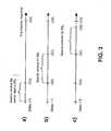
Figure 1 has already been described above.Figures 2 and3a-3c illustrate by way of example the principle of the method according to the invention employed in a cellular communication system. The communication system comprises a mobile station and a cellular network with a plurality of cells, each of which is served by another base station. The communication system enables certain location services. Currently, the location of the mobile station is to be determined using these location services.Figure 2 indicates various distances in the communication system.Several cells - The mobile station MS is located in a
server cell 20. Theserver cell 20 extends from location O to location B. A server base station BS0 serving theserver cell 20 is located in the center of thiscell 20 at position A. A first neighboringcell 21 extends from location B to location D. A base station BS1 serving cell 21 is located in the center of thiscell 21 at position C. A second neighboring cell BS2 begins at location D and extends beyond location E. A base station BS2 serving cell 22 is located in the center of thiscell 22 at position E. Further base stations may follow accordingly and extend at the most up to location X. The total length of the impulse response profile of signals transmitted by the base stations BS0, BS1, BS2 covers the distance from location O to location X. - The mobile station MS now determines the distance to each of the base stations BS0, BS1, BS2, in order to estimate its current location.
- The server base station BS0 is known, before the measurements for the location service start. The server base station BS0 knows its own location and cell size and moreover the locations and the covering ranges of the other base stations BS1, BS2.
- It is assumed that a communication is going on between the mobile station MS and the server base station BS0. During this communication, the server base station BS0 transmits the geometrical information and information on the cell size and covering ranges of the base stations to the mobile station MS. For cell size and covering ranges, e.g. an indication of the respective maximum distance from the base station to the boarder of the cell or the coverage area can be provided.
- Based on the received information, the mobile station MS then determines a dedicated search window for each of the base stations BS0, BS1, BS2 from which it might receive signals.
- The resulting search windows are indicated in
figures 3a to 3c . Each of the figures shows a time line with the delay of the impulse response between 0 and |OX|. |OX| is a delay which a signal undergoes on a transmission path of the length from location O to location X. - For the server base station BS0 itself, the searching range has to cover a circular area having a radius of the distance between locations O and A, since the mobile station MS is known to be located in the
server cell 20. The mobile station MS thus determines a search window comprising a delay from zero to a delay |OA|, which is the propagation time required on a direct path over a distance from O to A. This search window for the server base station BS0 is indicated infigure 3a . All components outside of this range in the impulse response can be excluded by the mobile station MS in the acquisition for the server base station BS0. - Since the mobile station MS is located in the
server cell 20, further the minimum distance between base station BS1 and the mobile station MS is known to be the distance between locations B and C, and the maximum distance between base station ES, and the mobile station MS is known to be the distance between locations O and C. Thus, for base station BS1, a search window is determined which covers corresponding delays |OA| to |OC|, where a delay |OA| is equal to a delay |BC|. This search window is indicated infigure 3b . - Since the mobile station MS is known to be located in the
server cell 20, further the minimum distance between base station BS2 and the mobile station MS is known to be the distance between locations B and E, and the maximum distance between base station BS2 and the mobile station MS is known to be the distance between locations O and E. Thus, for base station BS2, a search window is determined which covers corresponding delays |OC| to |OE|, where a delay |OC| is equal to delay |BE|. This search window is indicated infigure 3c . - The search window might be further be limited by available information on the coverage rage of the neighboring base stations BS1, BS2. For example, in case the mobile station MS was informed that the covering range of base station BS2 has only a radius of A-E, the searching range could further be restricted from A to B, and the search window correspondingly to delays from |OC| to |OD|.
- In the described example, the mobile station MS determines the search windows based on information received from the server base station BS0. Alternatively, the server base station BS0 could determine the search window for each of the base stations BS0, BS1, BS2 and provide the mobile station MS only with information on these search windows.
- In either case, the mobile station MS then estimates the delay of signals arriving from different base stations BS0, BS1, BS2 by placing the determined search window in the impulse response profile of the received signals and by performing an edge detection within this search window. From the estimated delays, the mobile station MS calculates the respective distance to the base stations BS0, BS1, BS2. The current location of the mobile station MS can be assumed to lie at the intersection point of circles around the base stations BS0, BS1, BS2 with the respectively determined distance.
- With the proposed method, the searching range is shortened, and thereby the false-alarm rate is reduced in the acquisition. When assuming cells of equal size, as in the example presented in
figures 2 and3 , the searching range is shortened by about one third for base station BS1 and by about 3/5 for base station BS2 compared to the conventional approach. - In practice, of course, the cell covering ranges are overlapping to each other and the cell sizes and shapes are not the identical. Nevertheless, the search window can be designed by the mobile station to cover all possible delays for acquiring a specified base station similarly as described above.
Figure 4 is a flow chart illustrating an embodiment of the method according to the invention, which further shortens the searching range for acquiring neighboring base stations for a location service in a cellular communication system.- In a first step, a server base station BS0 provides a mobile station MS with information on the location of the server base station BS0 and of neighboring base stations BSi of the cellular network, with an indication of the maximum cell radius R0 of the server base station BS0, and with an indication of the covering ranges of the neighboring base stations BSi.
- In a next step, the mobile station MS determines a search window for the server base station BS0, as described above. The server base station BS0 serves a cell having a maximum radius of about R0. Thus, the determined search window has a size corresponding to a searching range of R0. After acquiring the server base station BS0, the mobile station MS then uses this search window for determining the delay of signals received from the server base station BS0. The mobile station MS is able to calculate from this delay the distance Do to the server base station BS0 at which the mobile station MS is currently located.
Figure 5 shows for illustration a cellular environment with server base station BS0, radius R0 and determined distance Do. - For estimating the distance to further base stations BSi, the mobile station MS combines the received geometrical information and information on already acquired base stations.
- The mobile station MS first selects the closest neighboring base station BS1. The neighboring base station BS1 serves a cell with a maximum radius of about R1, which cell is partly overlapping with the cell served by the server base station BS0.
- In the example presented with reference to
figures 2 and3 , the searching range for base station BS1 would now be about 2R0. The mobile station MS knows already, however, that it is located on a defined ring around the server base station BS0, indicated infigure 5 with a dotted line. This ring has a distance of Do to the server base station BS0. The searching range for base station BS1 can thus be placed between D11, which corresponds to the distance between base station BS1 and the server base station BS0 minus D0, and D12, which corresponds to the distance between neighboring base station BS1 and the serving base station BS0 plus D0. - The length of the required searching range is therefore 2D0, which can be much smaller than the range of 2R0 used in the example of
figures 2 and3a-c . - The mobile station MS acquires neighboring base station BS1, uses the received search window for determining the delay of signals received by this base station BS1, and from the delay the distance D1 to base station BS1.
- As long as the distance to a further base station BSi is desired, the mobile station MS continues selecting the respective next closest neighboring station BSi and determines for it a search window based on the location information for this base station and on the already obtained location information for the mobile station MS.
- For example, in the next itineration round, two base stations BS0, BS1 have already been acquired, and the distances D0, D1 of the mobile station MS to these base stations BS0, BS1 have been determined. The mobile station MS thus has to be located on an intersection of two rings, one of which surrounds base station BS0 with radius Do and the other one of which surrounds base station BS1 with radius D1. When searching for other base stations, this information can be used to limit the size of the search window to cover a very small searching range. The search window can be split in particular into two sub-windows to cover two small searching areas around the two intersection regions of the two rings. The indication of the covering range of the neighboring stations BSi can be used beforehand for checking whether the signals from a respective neighboring station BSi can reach the mobile station MS at all with a sufficient signal strength.
- The more base stations are acquired, the more accurate information on the location of the mobile station is obtained. The location information can be used in turn for acquiring additional base stations. The false-alarm rate can thereby be reduced to a minimum.
Figures 6 and7 are diagrams presenting simulation results which illustrate the improvements which can be achieved with the method according to the invention.Figure 6 depicts the false alarm rate over a set threshold for a searching range of 150m, 500m, 1000m and 5000m. The searching range corresponds directly to the size of the employed search window. A dedicated curve connects approximately the simulation results for each of the searching ranges. The threshold value indicates the strength a received signal has to have in order to be detected by the mobile station, and is indicated as a multiple of the noise mean with values from 0.5 to 3.5. The false alarm rate is the rate of those noise peaks which are wrongly detected to be a signal edge, since the threshold was set too low.- In a specific noise environment, the threshold is set according to a desired false alarm rate. It can be seen in
figure 6 that the smaller the searching range, the lower the threshold value, which is required in order to achieve the same false alarm rate. For example, the false alarm rate may be required to be less than 0.2. If the searching range can be limited to 150 meters, the threshold setting should be set higher than about 1.8. If the searching range is 2000 meters, in contrast, the threshold should be set higher than 2.6. This means that the signal power has to be the higher for a larger searching range. Thus, more neighboring base stations can be considered in the location service with a smaller search window obtained in accordance with the invention. Figure 7 shows the acquisition probability in percent over a set threshold for a searching range of 150m, 500m, 1000m and 5000m. Again, a dedicated curve connects approximately the simulation results for each of the searching ranges. A signal-to-noise ratio of 9 dB is assumed. The acquisition probability takes into account on the one hand the probability that a correct signal is detected and on the other hand the probability that a detected signal is not a noise signal. Since both depend in an contrasting manner on the selected threshold value, the resulting curves have a maximum and indicate thus an optimum threshold value.- As can be seen in
figure 7 , the signal acquisition probability increases when the searching rage is reduced. For example, if the searching range is 150 meters, the maximum acquisition probability can reach about 85 %, while if the searching range is 2000 meters, the maximum acquisition probability will only be about 67 %. Thus, the benefit obtained by shortening the searching range is evident. - It is to be noted that the described embodiments constitute only selected ones of a variety of possible embodiments of the invention.
Claims (22)
- Method comprising determining a search window based on location information available for a specific network element (BS2) of a network, said search window enabling an estimation of a delay of a signal received at a mobile station (MS) from said specific network element (BS2) within said search window for determining the location of said mobile station (MS),
characterized in that said search window is determined in addition based on a known distance of said mobile station (MS) to at least two other network elements (BS0,BS1), to which a respective distance was already determined based on delay measurements on signals from said at least two other network elements (BS0, BS1). - Method according to claim 1, wherein said at least two other network elements comprise a serving network element (BS0) serving a server cell in which said mobile station (MS) is currently located.
- Method according to one of the preceding claims, wherein said search window is selected such that it covers delays with which said signal arrives at intersection points of all circles around said at least two network elements (BS0,BS1) with a radius of the respectively determined distance.
- Method according to claim 3, wherein said search window is subdivided into at least two sub-windows, each covering delays with which said signal arrives at a respective intersection point.
- Method according to one of the preceding claims, wherein a respective search window is determined for at least two specific network elements (BS1,BS2) in the order of their distance to said mobile station (MS), beginning with the network element (BS1) which is the closest to said mobile station (MS).
- Method according to one of the preceding claims, wherein a search window is determined for at least two specific network elements in the order of the signal strength at said mobile station of signals transmitted by said network elements, beginning with the network element providing the strongest signal.
- Method according to one of the preceding claims, wherein said search window is limited in addition based on the covering range of said specific network element (BS2).
- Method according to one of the preceding claims, further comprising determining a threshold value based on the size of a determined search window, which threshold value defines the minimum signal strength of signals received at said mobile station for which a delay is to be estimated.
- Method according to one of the preceding claims, further comprising estimating a delay of a signal received at said mobile station (MS) from said specific network element (BS2) within a determined search window for determining the location of said mobile station (MS).
- Device (MS;BS0) comprising means for determining a search window based on location information available for a specific network element (BS2) of a network, said search window enabling an estimation of a delay of a signal received at a mobile station (MS) from said specific network element (BS2) within said search window for determining the location of said mobile station (MS),characterized in that said means are configured to determine said search window in addition based on a known distance of said mobile station (MS) to at least two other network elements (BS0,BS1), to which a respective distance was already determined based on delay measurements on signals from said at least two other network elements (BS0,BS1).
- Device (MS;BS0) according to claim 10, wherein said at least two other network elements comprise a serving network element (BS0) serving a server cell in which said mobile station (MS) is currently located.
- Device (MS;BS0) according to claim 10 or 11, wherein said means are further configured to select said search window such that it covers delays with which said signal arrives at intersection points of all circles around said at least two network elements (BS0,BS1) with a radius of the respectively determined distance.
- Device (MS;BS0) according to claim 12, wherein said means are further configured to subdivide said search window into at least two sub-windows, each covering delays with which said signal arrives at a respective intersection point.
- Device (MS;BS0) according to one of claims 10 to 13, wherein said means are further configured to determine a respective search window for at least two specific network elements (BS1,BS2) in the order of their distance to said mobile station (MS), beginning with the network element (BS1) which is the closest to said mobile station (MS).
- Device (MS;BS0) according to one of claims 10 to 14, wherein said means are further configured to determine a search window for at least two specific network elements in the order of the signal strength at said mobile station of signals transmitted by said network elements, beginning with the network element providing the strongest signal.
- Device (MS;BS0) according to one of claims 10 to 15, wherein said means are further configured to limit said search window in addition based on the covering range of said specific network element (BS2).
- Device (MS;BS0) according to one of claims 10 to 16, wherein said means are further configured to determine a threshold value based on the size of a determined search window, which threshold value defines the minimum signal strength of signals received at said mobile station for which a delay is to be estimated.
- Device (MS;BS0) according to one of claims 10 to 17, wherein said device is a mobile station (MS) further comprising means for receiving signals from a plurality of network elements (BS0,BS1,BS2) of a network for determining the location of said mobile station (MS) and means for estimating a delay of received signals using a respectively determined search window.
- Device (MS;BS0) according to one of claims 10 to 17, wherein said device is a network element (BS0) for a network comprising means for transmitting signals for determining the location of a mobile station (MS) to said mobile station (MS) and means for transmitting information on a determined search window to said mobile station (MS).
- Communication system comprising- at least three network elements (BS0,BS1,BS2) for transmitting signals for determining the location of a mobile station (MS);- at least one mobile station (MS) with means for determining a delay of received signals based on a search window; and- means for determining a search window based on location information available for a specific one of said network elements (BS2);characterized in that said means for determining a search window are configured to determine said search window in addition based on a known distance of said mobile station (MS) to said at least two other network elements (BS0,BS1), to which a respective distance was already determined based on delay measurements on signals from said at least two other network elements (BS0,BS1).
- Communication system according to claim 20, wherein said means for determining a search window are comprised in at least one of said at least three network elements (BS0, BS1, BS2) .
- Communication system according to claim 20, wherein said means for determining a search window are comprised in said at least one mobile station (MS).
Applications Claiming Priority (1)
| Application Number | Priority Date | Filing Date | Title |
|---|---|---|---|
| PCT/IB2002/005055WO2004052039A1 (en) | 2002-12-02 | 2002-12-02 | Estimation of a signal delay |
Publications (2)
| Publication Number | Publication Date |
|---|---|
| EP1568244A1 EP1568244A1 (en) | 2005-08-31 |
| EP1568244B1true EP1568244B1 (en) | 2009-10-07 |
Family
ID=32448798
Family Applications (1)
| Application Number | Title | Priority Date | Filing Date |
|---|---|---|---|
| EP02779845AExpired - LifetimeEP1568244B1 (en) | 2002-12-02 | 2002-12-02 | Estimation of a signal delay |
Country Status (7)
| Country | Link |
|---|---|
| US (1) | US7218939B2 (en) |
| EP (1) | EP1568244B1 (en) |
| CN (1) | CN100536594C (en) |
| AT (1) | ATE445303T1 (en) |
| AU (1) | AU2002343176A1 (en) |
| DE (1) | DE60233981D1 (en) |
| WO (1) | WO2004052039A1 (en) |
Families Citing this family (12)
| Publication number | Priority date | Publication date | Assignee | Title |
|---|---|---|---|---|
| US7110779B2 (en)* | 2004-01-29 | 2006-09-19 | Harris Corporation | Wireless communications system including a wireless device locator and related methods |
| US7702338B2 (en)* | 2004-09-29 | 2010-04-20 | Qualcomm Incorporated | Method for finding the location of a mobile terminal in a cellular radio system |
| JP4651364B2 (en)* | 2004-11-17 | 2011-03-16 | 富士通株式会社 | Phase adjustment method and apparatus |
| CN100349493C (en)* | 2004-12-14 | 2007-11-14 | 上海华为技术有限公司 | Method for reinforcing search under omnidirectional emission sector receiving mode |
| CN100421526C (en)* | 2005-12-20 | 2008-09-24 | 华为技术有限公司 | Method for user terminal to report location information |
| CN101810022A (en)* | 2007-08-09 | 2010-08-18 | 北电网络有限公司 | Automatic Discovery and Management of Base Station Neighbors in Wireless Networks |
| US20090125630A1 (en)* | 2007-11-09 | 2009-05-14 | Qualcomm Incorporated | Method and apparatus for defining a search window based on distance between access points |
| JP5100536B2 (en)* | 2008-07-03 | 2012-12-19 | 三菱電機株式会社 | Delay profile estimation apparatus and delay profile estimation method |
| US8073463B2 (en)* | 2008-10-06 | 2011-12-06 | Andrew, Llc | System and method of UMTS UE location using uplink dedicated physical control channel and downlink synchronization channel |
| US9622207B1 (en)* | 2016-03-22 | 2017-04-11 | Qualcomm Incorporated | Wireless transmit station search window reduction |
| CN110392633B (en)* | 2017-04-14 | 2021-11-05 | 惠普发展公司,有限责任合伙企业 | Delay element for activation signal |
| GB2572336B (en)* | 2018-03-26 | 2022-02-02 | Samsung Electronics Co Ltd | Improvements in and relating to random access in a telecommunication network |
Family Cites Families (12)
| Publication number | Priority date | Publication date | Assignee | Title |
|---|---|---|---|---|
| JP3858433B2 (en)* | 1998-03-30 | 2006-12-13 | ソニー株式会社 | Pilot signal detection method and receiver |
| US6370397B1 (en)* | 1998-05-01 | 2002-04-09 | Telefonaktiebolaget Lm Ericsson (Publ) | Search window delay tracking in code division multiple access communication systems |
| US6748224B1 (en)* | 1998-12-16 | 2004-06-08 | Lucent Technologies Inc. | Local positioning system |
| US6542743B1 (en)* | 1999-08-31 | 2003-04-01 | Qualcomm, Incorporated | Method and apparatus for reducing pilot search times utilizing mobile station location information |
| US6191738B1 (en)* | 1999-09-30 | 2001-02-20 | Motorola, Inc. | Method and apparatus for locating a remote unit within a communication system |
| US6775252B1 (en)* | 2000-03-31 | 2004-08-10 | Qualcomm, Inc. | Dynamic adjustment of search window size in response to signal strength |
| JP3740953B2 (en)* | 2000-06-13 | 2006-02-01 | 株式会社日立製作所 | Wireless position measuring terminal and wireless position measuring system |
| US6760599B1 (en)* | 2000-09-29 | 2004-07-06 | Arraycomm, Inc. | Method and apparatus for selecting a base station |
| US6876859B2 (en)* | 2001-07-18 | 2005-04-05 | Trueposition, Inc. | Method for estimating TDOA and FDOA in a wireless location system |
| US7392045B2 (en)* | 2002-01-15 | 2008-06-24 | Marvell International Ltd. | Method and apparatus for searching for a base station using an adaptable search window |
| US7359707B2 (en)* | 2002-01-23 | 2008-04-15 | Leap Wireless International, Inc. | Wireless communications handoff method and system employing such |
| CN1292261C (en)* | 2002-01-24 | 2006-12-27 | 华为技术有限公司 | A Method for Positioning Measurement of Mobile Station |
- 2002
- 2002-12-02EPEP02779845Apatent/EP1568244B1/ennot_activeExpired - Lifetime
- 2002-12-02ATAT02779845Tpatent/ATE445303T1/ennot_activeIP Right Cessation
- 2002-12-02AUAU2002343176Apatent/AU2002343176A1/ennot_activeAbandoned
- 2002-12-02CNCNB028299817Apatent/CN100536594C/ennot_activeExpired - Fee Related
- 2002-12-02WOPCT/IB2002/005055patent/WO2004052039A1/ennot_activeApplication Discontinuation
- 2002-12-02DEDE60233981Tpatent/DE60233981D1/ennot_activeExpired - Lifetime
- 2003
- 2003-12-02USUS10/727,113patent/US7218939B2/ennot_activeExpired - Lifetime
Also Published As
| Publication number | Publication date |
|---|---|
| ATE445303T1 (en) | 2009-10-15 |
| US7218939B2 (en) | 2007-05-15 |
| DE60233981D1 (en) | 2009-11-19 |
| US20050059411A1 (en) | 2005-03-17 |
| CN1860817A (en) | 2006-11-08 |
| CN100536594C (en) | 2009-09-02 |
| AU2002343176A1 (en) | 2004-06-23 |
| WO2004052039A1 (en) | 2004-06-17 |
| EP1568244A1 (en) | 2005-08-31 |
Similar Documents
| Publication | Publication Date | Title |
|---|---|---|
| EP1286174B1 (en) | Radio handset and position location system | |
| EP1851978B1 (en) | System and method for asset location in wireless networks | |
| EP1413163B1 (en) | System and method of estimating earliest arrival of cdma forward link signals | |
| US7345630B2 (en) | System and method for position detection of a terminal in a network | |
| EP1478202B1 (en) | A method of locating and measuring a mobile station | |
| US5970414A (en) | Method for estimating a mobile-telephone's location | |
| US6871077B2 (en) | System and method for geolocating a wireless mobile unit from a single base station using repeatable ambiguous measurements | |
| US20010051527A1 (en) | Wireless position measurement terminal and wireless position measurement system | |
| US6658258B1 (en) | Method and apparatus for estimating the location of a mobile terminal | |
| US7933610B2 (en) | Method and apparatus to select an optimum site and/or sector to provide geo-location data | |
| US20050227703A1 (en) | Method for using base station power measurements to detect position of mobile stations | |
| US20060141998A1 (en) | Wireless communication network measurement data collection using infrastructure overlay-based handset location systems | |
| EP1568244B1 (en) | Estimation of a signal delay | |
| JP2001500256A (en) | Position finding method and device in communication system | |
| US6256494B1 (en) | Method of and apparatus for estimating a characteristic of a signal | |
| JP2001268622A (en) | Mobile station current position recognition method and current position recognition device, and mobile station and base station thereof | |
| US7486233B2 (en) | Method and system of positioning | |
| KR101723120B1 (en) | Informing Method of Location in Indoor Space | |
| JP4168508B2 (en) | Radio communication system and radio communication apparatus for mobile station used therefor | |
| KR100736419B1 (en) | Signal delay estimation | |
| KR102226683B1 (en) | Position estimation method and apparatus for ue based on multi-downlink information of multi-frequencies | |
| CN113965988A (en) | Positioning method, device, equipment and storage medium | |
| KR100574655B1 (en) | Subscriber location information service method of wireless communication network | |
| US6885339B2 (en) | Discrete radiation source location | |
| KR19990075135A (en) | Code division multiple access method Mobile terminal's location search method |
Legal Events
| Date | Code | Title | Description |
|---|---|---|---|
| PUAI | Public reference made under article 153(3) epc to a published international application that has entered the european phase | Free format text:ORIGINAL CODE: 0009012 | |
| 17P | Request for examination filed | Effective date:20050506 | |
| AK | Designated contracting states | Kind code of ref document:A1 Designated state(s):AT BE BG CH CY CZ DE DK EE ES FI FR GB GR IE IT LI LU MC NL PT SE SK TR | |
| AX | Request for extension of the european patent | Extension state:AL LT LV MK RO | |
| DAX | Request for extension of the european patent (deleted) | ||
| 17Q | First examination report despatched | Effective date:20061221 | |
| GRAP | Despatch of communication of intention to grant a patent | Free format text:ORIGINAL CODE: EPIDOSNIGR1 | |
| RIC1 | Information provided on ipc code assigned before grant | Ipc:H04W 64/00 20090101AFI20090227BHEP | |
| RBV | Designated contracting states (corrected) | Designated state(s):AT BE BG CH CY CZ DE DK EE ES FI FR GB GR IE IT LI LU MC NL PT SE SI SK TR | |
| GRAS | Grant fee paid | Free format text:ORIGINAL CODE: EPIDOSNIGR3 | |
| GRAA | (expected) grant | Free format text:ORIGINAL CODE: 0009210 | |
| AK | Designated contracting states | Kind code of ref document:B1 Designated state(s):AT BE BG CH CY CZ DE DK EE ES FI FR GB GR IE IT LI LU MC NL PT SE SI SK TR | |
| REG | Reference to a national code | Ref country code:GB Ref legal event code:FG4D | |
| REG | Reference to a national code | Ref country code:CH Ref legal event code:EP | |
| REG | Reference to a national code | Ref country code:IE Ref legal event code:FG4D | |
| REF | Corresponds to: | Ref document number:60233981 Country of ref document:DE Date of ref document:20091119 Kind code of ref document:P | |
| PG25 | Lapsed in a contracting state [announced via postgrant information from national office to epo] | Ref country code:SI Free format text:LAPSE BECAUSE OF FAILURE TO SUBMIT A TRANSLATION OF THE DESCRIPTION OR TO PAY THE FEE WITHIN THE PRESCRIBED TIME-LIMIT Effective date:20091007 | |
| NLV1 | Nl: lapsed or annulled due to failure to fulfill the requirements of art. 29p and 29m of the patents act | ||
| PG25 | Lapsed in a contracting state [announced via postgrant information from national office to epo] | Ref country code:SE Free format text:LAPSE BECAUSE OF FAILURE TO SUBMIT A TRANSLATION OF THE DESCRIPTION OR TO PAY THE FEE WITHIN THE PRESCRIBED TIME-LIMIT Effective date:20091007 Ref country code:ES Free format text:LAPSE BECAUSE OF FAILURE TO SUBMIT A TRANSLATION OF THE DESCRIPTION OR TO PAY THE FEE WITHIN THE PRESCRIBED TIME-LIMIT Effective date:20100118 Ref country code:PT Free format text:LAPSE BECAUSE OF FAILURE TO SUBMIT A TRANSLATION OF THE DESCRIPTION OR TO PAY THE FEE WITHIN THE PRESCRIBED TIME-LIMIT Effective date:20100208 Ref country code:FI Free format text:LAPSE BECAUSE OF FAILURE TO SUBMIT A TRANSLATION OF THE DESCRIPTION OR TO PAY THE FEE WITHIN THE PRESCRIBED TIME-LIMIT Effective date:20091007 | |
| PG25 | Lapsed in a contracting state [announced via postgrant information from national office to epo] | Ref country code:BE Free format text:LAPSE BECAUSE OF FAILURE TO SUBMIT A TRANSLATION OF THE DESCRIPTION OR TO PAY THE FEE WITHIN THE PRESCRIBED TIME-LIMIT Effective date:20091007 Ref country code:AT Free format text:LAPSE BECAUSE OF FAILURE TO SUBMIT A TRANSLATION OF THE DESCRIPTION OR TO PAY THE FEE WITHIN THE PRESCRIBED TIME-LIMIT Effective date:20091007 | |
| PG25 | Lapsed in a contracting state [announced via postgrant information from national office to epo] | Ref country code:DK Free format text:LAPSE BECAUSE OF FAILURE TO SUBMIT A TRANSLATION OF THE DESCRIPTION OR TO PAY THE FEE WITHIN THE PRESCRIBED TIME-LIMIT Effective date:20091007 Ref country code:EE Free format text:LAPSE BECAUSE OF FAILURE TO SUBMIT A TRANSLATION OF THE DESCRIPTION OR TO PAY THE FEE WITHIN THE PRESCRIBED TIME-LIMIT Effective date:20091007 Ref country code:MC Free format text:LAPSE BECAUSE OF NON-PAYMENT OF DUE FEES Effective date:20100701 Ref country code:BG Free format text:LAPSE BECAUSE OF FAILURE TO SUBMIT A TRANSLATION OF THE DESCRIPTION OR TO PAY THE FEE WITHIN THE PRESCRIBED TIME-LIMIT Effective date:20100107 Ref country code:NL Free format text:LAPSE BECAUSE OF FAILURE TO SUBMIT A TRANSLATION OF THE DESCRIPTION OR TO PAY THE FEE WITHIN THE PRESCRIBED TIME-LIMIT Effective date:20091007 | |
| REG | Reference to a national code | Ref country code:CH Ref legal event code:PL | |
| PLBE | No opposition filed within time limit | Free format text:ORIGINAL CODE: 0009261 | |
| STAA | Information on the status of an ep patent application or granted ep patent | Free format text:STATUS: NO OPPOSITION FILED WITHIN TIME LIMIT | |
| PG25 | Lapsed in a contracting state [announced via postgrant information from national office to epo] | Ref country code:SK Free format text:LAPSE BECAUSE OF FAILURE TO SUBMIT A TRANSLATION OF THE DESCRIPTION OR TO PAY THE FEE WITHIN THE PRESCRIBED TIME-LIMIT Effective date:20091007 Ref country code:CZ Free format text:LAPSE BECAUSE OF FAILURE TO SUBMIT A TRANSLATION OF THE DESCRIPTION OR TO PAY THE FEE WITHIN THE PRESCRIBED TIME-LIMIT Effective date:20091007 | |
| 26N | No opposition filed | Effective date:20100708 | |
| PG25 | Lapsed in a contracting state [announced via postgrant information from national office to epo] | Ref country code:LI Free format text:LAPSE BECAUSE OF NON-PAYMENT OF DUE FEES Effective date:20091231 Ref country code:IE Free format text:LAPSE BECAUSE OF NON-PAYMENT OF DUE FEES Effective date:20091202 Ref country code:GR Free format text:LAPSE BECAUSE OF FAILURE TO SUBMIT A TRANSLATION OF THE DESCRIPTION OR TO PAY THE FEE WITHIN THE PRESCRIBED TIME-LIMIT Effective date:20100108 Ref country code:CH Free format text:LAPSE BECAUSE OF NON-PAYMENT OF DUE FEES Effective date:20091231 | |
| PG25 | Lapsed in a contracting state [announced via postgrant information from national office to epo] | Ref country code:IT Free format text:LAPSE BECAUSE OF FAILURE TO SUBMIT A TRANSLATION OF THE DESCRIPTION OR TO PAY THE FEE WITHIN THE PRESCRIBED TIME-LIMIT Effective date:20091007 | |
| PGFP | Annual fee paid to national office [announced via postgrant information from national office to epo] | Ref country code:GB Payment date:20101201 Year of fee payment:9 | |
| PG25 | Lapsed in a contracting state [announced via postgrant information from national office to epo] | Ref country code:LU Free format text:LAPSE BECAUSE OF NON-PAYMENT OF DUE FEES Effective date:20091202 | |
| PG25 | Lapsed in a contracting state [announced via postgrant information from national office to epo] | Ref country code:TR Free format text:LAPSE BECAUSE OF FAILURE TO SUBMIT A TRANSLATION OF THE DESCRIPTION OR TO PAY THE FEE WITHIN THE PRESCRIBED TIME-LIMIT Effective date:20091007 | |
| PG25 | Lapsed in a contracting state [announced via postgrant information from national office to epo] | Ref country code:CY Free format text:LAPSE BECAUSE OF FAILURE TO SUBMIT A TRANSLATION OF THE DESCRIPTION OR TO PAY THE FEE WITHIN THE PRESCRIBED TIME-LIMIT Effective date:20091007 | |
| GBPC | Gb: european patent ceased through non-payment of renewal fee | Effective date:20111202 | |
| PG25 | Lapsed in a contracting state [announced via postgrant information from national office to epo] | Ref country code:GB Free format text:LAPSE BECAUSE OF NON-PAYMENT OF DUE FEES Effective date:20111202 | |
| PGFP | Annual fee paid to national office [announced via postgrant information from national office to epo] | Ref country code:FR Payment date:20130107 Year of fee payment:11 | |
| REG | Reference to a national code | Ref country code:FR Ref legal event code:ST Effective date:20140829 | |
| PG25 | Lapsed in a contracting state [announced via postgrant information from national office to epo] | Ref country code:FR Free format text:LAPSE BECAUSE OF NON-PAYMENT OF DUE FEES Effective date:20131231 | |
| REG | Reference to a national code | Ref country code:DE Ref legal event code:R081 Ref document number:60233981 Country of ref document:DE Owner name:NOKIA TECHNOLOGIES OY, FI Free format text:FORMER OWNER: NOKIA CORP., 02610 ESPOO, FI | |
| PGFP | Annual fee paid to national office [announced via postgrant information from national office to epo] | Ref country code:DE Payment date:20151125 Year of fee payment:14 | |
| REG | Reference to a national code | Ref country code:DE Ref legal event code:R119 Ref document number:60233981 Country of ref document:DE | |
| PG25 | Lapsed in a contracting state [announced via postgrant information from national office to epo] | Ref country code:DE Free format text:LAPSE BECAUSE OF NON-PAYMENT OF DUE FEES Effective date:20170701 |