EP1567070B1 - Adjustable length tap and method for drilling and tapping a bore in bone - Google Patents
Adjustable length tap and method for drilling and tapping a bore in boneDownload PDFInfo
- Publication number
- EP1567070B1 EP1567070B1EP03783566AEP03783566AEP1567070B1EP 1567070 B1EP1567070 B1EP 1567070B1EP 03783566 AEP03783566 AEP 03783566AEP 03783566 AEP03783566 AEP 03783566AEP 1567070 B1EP1567070 B1EP 1567070B1
- Authority
- EP
- European Patent Office
- Prior art keywords
- stop collar
- assembly
- shaft
- collar
- tap
- Prior art date
- Legal status (The legal status is an assumption and is not a legal conclusion. Google has not performed a legal analysis and makes no representation as to the accuracy of the status listed.)
- Expired - Lifetime
Links
- 238000005553drillingMethods0.000titleclaimsdescription39
- 210000000988bone and boneAnatomy0.000titleclaimsdescription28
- 238000010079rubber tappingMethods0.000titleclaimsdescription9
- 238000000034methodMethods0.000titledescription14
- 238000005520cutting processMethods0.000claimsdescription26
- 239000000560biocompatible materialSubstances0.000claimsdescription3
- 239000000696magnetic materialSubstances0.000claimsdescription3
- 239000004417polycarbonateSubstances0.000claimsdescription3
- 239000000463materialSubstances0.000description20
- 230000008878couplingEffects0.000description7
- 238000010168coupling processMethods0.000description7
- 238000005859coupling reactionMethods0.000description7
- 230000035515penetrationEffects0.000description7
- 229920003023plasticPolymers0.000description6
- 239000004033plasticSubstances0.000description5
- 230000008859changeEffects0.000description4
- 230000000007visual effectEffects0.000description4
- 230000001965increasing effectEffects0.000description3
- 229910001220stainless steelInorganic materials0.000description3
- 239000010935stainless steelSubstances0.000description3
- 238000004659sterilization and disinfectionMethods0.000description3
- 229910000619316 stainless steelInorganic materials0.000description2
- 230000000694effectsEffects0.000description2
- 230000036512infertilityEffects0.000description2
- 210000004373mandibleAnatomy0.000description2
- 230000007246mechanismEffects0.000description2
- 239000002985plastic filmSubstances0.000description2
- 229920000515polycarbonatePolymers0.000description2
- 230000002441reversible effectEffects0.000description2
- 230000001954sterilising effectEffects0.000description2
- 238000001356surgical procedureMethods0.000description2
- 210000001519tissueAnatomy0.000description2
- 229920002799BoPETPolymers0.000description1
- 239000004425MakrolonSubstances0.000description1
- 239000005041Mylar™Substances0.000description1
- 239000004698PolyethyleneSubstances0.000description1
- 229910001069Ti alloyInorganic materials0.000description1
- RTAQQCXQSZGOHL-UHFFFAOYSA-NTitaniumChemical compound[Ti]RTAQQCXQSZGOHL-UHFFFAOYSA-N0.000description1
- 238000005299abrasionMethods0.000description1
- 239000010796biological wasteSubstances0.000description1
- 210000004556brainAnatomy0.000description1
- 238000000576coating methodMethods0.000description1
- 238000010276constructionMethods0.000description1
- 239000004035construction materialSubstances0.000description1
- 230000003247decreasing effectEffects0.000description1
- 230000002708enhancing effectEffects0.000description1
- 238000009472formulationMethods0.000description1
- 230000006870functionEffects0.000description1
- 239000007943implantSubstances0.000description1
- 238000004519manufacturing processMethods0.000description1
- 229910001092metal group alloyInorganic materials0.000description1
- 239000000203mixtureSubstances0.000description1
- 230000000399orthopedic effectEffects0.000description1
- 238000004806packaging method and processMethods0.000description1
- -1polyethylenePolymers0.000description1
- 229920000573polyethylenePolymers0.000description1
- 230000000750progressive effectEffects0.000description1
- 238000010008shearingMethods0.000description1
- 210000004872soft tissueAnatomy0.000description1
- 230000000087stabilizing effectEffects0.000description1
- 238000003860storageMethods0.000description1
- 229910052719titaniumInorganic materials0.000description1
- 239000010936titaniumSubstances0.000description1
- 230000007704transitionEffects0.000description1
Images


Classifications
- A—HUMAN NECESSITIES
- A61—MEDICAL OR VETERINARY SCIENCE; HYGIENE
- A61B—DIAGNOSIS; SURGERY; IDENTIFICATION
- A61B17/00—Surgical instruments, devices or methods
- A61B17/16—Instruments for performing osteoclasis; Drills or chisels for bones; Trepans
- A61B17/1613—Component parts
- A61B17/1633—Sleeves, i.e. non-rotating parts surrounding the bit shaft, e.g. the sleeve forming a single unit with the bit shaft
- A—HUMAN NECESSITIES
- A61—MEDICAL OR VETERINARY SCIENCE; HYGIENE
- A61B—DIAGNOSIS; SURGERY; IDENTIFICATION
- A61B17/00—Surgical instruments, devices or methods
- A61B17/16—Instruments for performing osteoclasis; Drills or chisels for bones; Trepans
- A—HUMAN NECESSITIES
- A61—MEDICAL OR VETERINARY SCIENCE; HYGIENE
- A61B—DIAGNOSIS; SURGERY; IDENTIFICATION
- A61B17/00—Surgical instruments, devices or methods
- A61B17/16—Instruments for performing osteoclasis; Drills or chisels for bones; Trepans
- A61B17/1655—Instruments for performing osteoclasis; Drills or chisels for bones; Trepans for tapping
- A—HUMAN NECESSITIES
- A61—MEDICAL OR VETERINARY SCIENCE; HYGIENE
- A61B—DIAGNOSIS; SURGERY; IDENTIFICATION
- A61B17/00—Surgical instruments, devices or methods
- A61B17/32—Surgical cutting instruments
- A—HUMAN NECESSITIES
- A61—MEDICAL OR VETERINARY SCIENCE; HYGIENE
- A61B—DIAGNOSIS; SURGERY; IDENTIFICATION
- A61B17/00—Surgical instruments, devices or methods
- A61B2017/00831—Material properties
- A61B2017/00902—Material properties transparent or translucent
- A61B2017/00907—Material properties transparent or translucent for light
- A—HUMAN NECESSITIES
- A61—MEDICAL OR VETERINARY SCIENCE; HYGIENE
- A61B—DIAGNOSIS; SURGERY; IDENTIFICATION
- A61B90/00—Instruments, implements or accessories specially adapted for surgery or diagnosis and not covered by any of the groups A61B1/00 - A61B50/00, e.g. for luxation treatment or for protecting wound edges
- A61B90/03—Automatic limiting or abutting means, e.g. for safety
- A61B2090/033—Abutting means, stops, e.g. abutting on tissue or skin
- A61B2090/036—Abutting means, stops, e.g. abutting on tissue or skin abutting on tissue or skin
Definitions
- the present inventionis directed to a self-drilling tap for use in orthopaedic procedures to treat bone, and in particular to a device for drilling and tapping holes in bone to accommodate screws used in cranio-facial, mandible, pelvic and other orthopaedic procedures.
- U.S. Patent No. US 4,341,206discloses a tool for forming a stepped blind hole in bone for receipt of a fracture reducing and stabilizing surgical implant.
- the toolcomprises a small diameter drill portion axially adjustable with respect to a larger diameter reamer portion.
- a conical portionincludes cutting surfaces to chamfer the entrance of the hole and also includes non-cutting portions which serve to limit penetration of the tool into the bone.
- the toolis cannulated to allow its use in conjunction with a previously installed Kirschner guide wire.
- DE 38 00 482 A1 and DE 3622 676 A1also disclose an adjustable length tap assembly.
- the present inventionis directed to a tap assembly according to claim 1 which may be adjusted by a user to drill and tap holes in bone in order to accommodate screws of various lengths.
- the adjustable length tapcomprises a shaft, a stop collar and a locking collar which cooperate to expose and set an effective length of cutting thread located on the tip of the shaft.
- the shafthas a longitudinal axis, a proximal end, and a distal end with cutting threads for drilling and tapping holes in bone.
- the adjustable length assemblyalso includes stop collar having proximal and distal ends. The distal end of the stop collar is configured and dimensioned to provide a stop for the self-drilling tap.
- the stop collaris configured and dimensioned to be translatable along the longitudinal axis of the shaft and to contact against a surface to block advancement of the tap at a maximum depth of the threaded hole.
- the shaftpreferably includes length indicator marks, the length indicator marks being configured and dimensioned to allow for a controlled setting of the effective length of the adjustable length tap assembly. Each length indicator mark is preferably configured and dimensioned to correspond with one effective length.
- each length indicator markis preferably configured and dimensioned to be visibly aligned with the proximal end of the stop collar, when the effective length is set.
- each length indicator markis selectively disposed on the shaft, and each length indicator mark is visibly identified by indicia.
- the shaftis preferably made from bio-compatible materials and may be made from non-magnetic materials.
- the stop collarhas a body having an inner surface and an outer surface. A portion of the inner surface is configured and dimensioned to engage with the shaft in at least one predetermined location.
- the stop collarpreferably has one or more fingers, and the shaft preferably has one or more grooves.
- the one or more fingersmay have inner and outer surfaces and at least one projection or nub formed on the inner surface.
- the projectionpreferably is configured and dimensioned to interact with the grooves to prevent translational movement of the stop collar along the longitudinal axis of the shaft.
- the one or more fingerspreferably is formed by at least two slots. Each of the two slots preferably extend from the outer surface of the stop collar to the inner surface of the stop collar.
- the stop collarhas at least two fingers, the fingers being substantially identical and arranged in a substantially symmetrical configuration about a central axis of the stop collar.
- the at least one projection on the stop collarhas a mid-point
- the at least one groove on the shafthas a mid-point.
- a first distance measured from the mid-point of the at least one projection to the proximal end of the stop collarpreferably is related to a second distance measured from the mid-point of the at least one groove to a corresponding length indicator mark on the shaft. The first distance preferably is substantially equal to the second distance.
- the groovespreferably extend continuously about the shaft, and the grooves preferably are oriented substantially perpendicular to the longitudinal axis of the shaft. In an exemplary embodiment, the grooves are substantially equidistant from one another.
- the groovesmay also be substantially identical in size and shape.
- the adjustable length tap assemblyalso comprises a locking collar.
- the locking collaris configured and dimensioned to be received over at least a portion of the stop collar.
- the locking collaris configured and dimensioned to engage with the stop collar to set the effective length of the cutting threads, and to prevent movement of the stop collar along the longitudinal axis of the shaft.
- the locking collaralso, is preferably configured and dimensioned to bear against a structure on the outer surface of the one or more fingers to releasably engage the at least one nub with a groove on the shaft.
- the locking collarpreferably comprises a tubular member having a bore, and the proximal end of the locking collar preferably is capable of translating over the proximal end of the stop collar.
- at least a part of the locking collaris transparent, and the locking collar preferably is formed from a medical grade polycarbonate.
- the locking collar and the stop collarengage or mate with each other in at least two configurations, a first configuration which allows translational movement of the stop collar and locking collar together along the shaft, and a second configuration that prevents translational movement of the stop collar along the longitudinal axis of the shaft.
- the stop collar and locking collargenerally, are free to rotate about the shaft when the stop collar and locking collar engage in the second configuration.
- the present inventionis also directed to a surgical kit comprising the tap assembly of claim 1 for drilling and tapping holes in bone.
- the kitcomprises additional shafts each having a longitudinal axis, a proximal end and a distal end. At least a portion of each shaft should have cutting threads for drilling and tapping bores in bone.
- the kitmay also include a stop collar having proximal and distal ends, which preferably is configured and dimensioned to be translatable along the longitudinal axis of each of the shafts.
- the stop collarpreferably has a body having an inner surface and an outer surface, at least a portion of the inner surface being configured and dimensioned to engage with the at least one shaft in at least one predetermined location.
- the kitmay further include a locking collar comprising a member configured and dimensioned to be received over at least a portion of the stop collar.
- the locking collarpreferably is configured and dimensioned to engage or mate with the stop collar to set at least one effective length for the cutting threads and preferably to prevent movement of the stop collar along the longitudinal axis of the at least one shaft.
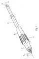
- FIG. 1shows an assembly 10 for use in drilling and tapping holes in bone.
- the assembly 10comprises a self-drilling tap 12 having a longitudinal axis 14, a stop collar 18, and a locking collar 20.
- the self-drilling tap 12may have a distal end 13 with cutting threads 16 adapted to drill and tap holes in bone.
- the stop collar 18 and locking collar 20may be moved along the self-drilling tap 12 to expose a portion of the cutting threads 16.
- the relative position of stop collar 18 and locking collar 20may be fixed along the longitudinal axis 14 of the self-drilling tap 12.
- the stop collar 18 and the locking collar 20may be free to rotate about the longitudinal axis 14 of the self-drilling tap, even though translational movement along the longitudinal axis 14 is prevented.
- the assembly 10may be used with other instruments such as a handle and guide plate (not shown) to drill and tap holes in bone.
- Detachable handles, guide plates, and drillsare representative of the instruments and other devices that may be used in conjunction with the adjustable length tap assembly. These instruments, however, may not always be required or may be replaced by different devices that perform similar, additional, or different functions.
- FIG. 2shows a cut away view of the adjustable length tap assembly.
- the stop collar 18 and the locking collar 20are shown in cross-section, and the shaft 22 is shown in plan view.
- the self-drilling tap 12includes a shaft 22 having a tip or distal end 13 with cutting threads 16.
- the tap 12further comprises a plurality of circumferential grooves 24, indica 26, such as for example lines, for marking the effective length 28 of the exposed portion of the cutting threads 16, and a coupling element 30 for connecting the self-drilling tap 12 to a handle or a drill (not shown) at the proximal end 31 thereof.
- the maximum outer diameter 32 of the cutting threads 16 and the length 34 of the tip 13, which contains the cutting threads,may be fixed.
- the dimensions of the tip 13, for any particular tap 12,may be based on the size and length of the screw for to be inserted in the bore.
- the dimensions of the tip 13may further be adapted to accommodate the thickness of a guide plate.
- a special screwmay be developed for use in a pelvic procedure, for example, and the dimensions of the tip 13 of the self-drilling tap 12 may be designed to accommodate that screw.
- one screw typemay have an outer diameter of 1.5 mm and a length of 3 mm, and the dimension of the tip 13 may be configured and dimensioned to create a tapped bore that is adapted for screws of that type.
- a self-drilling tapmay also be developed for larger or smaller screws.
- the cutting threads 16may be particularly adapted to cut and remove bone without damaging adjacent tissue.
- the threadsmay include sharp cutting flutes 36 and one or more straight flutes 38 for removing bone chips and cuttings from the bore. For example, two straight flutes aligned 180° from each other may be disposed on the tip.
- One of ordinary skill in the artwould readily appreciate that the number and configuration of cutting flutes 36 and straight flutes 38 may be widely varied, or in addition to or alternatively a wide variety of other configurations and combinations may be used.
- the shaft 22 of the tap 12may have an outer diameter 40 that is operably configured and dimensioned to slidably receive the stop collar 18 and the locking collar 20.
- a set of tapswhich may be adapted for screws having differing predetermined diameters and lengths, preferably may each have a shaft 22 of same diameter 40.
- the outer diameter 40 of the shaft 22may be about 3.0 mm.
- a set of self-drilling taps having different tip configurationsmay be supplied as a kit for use with one stop collar 18 and one locking collar 20. More than one stop collar 18 and more than one locking collar may also be supplied in the kit.
- a set of taps 12 having a different outer diametermay be supplied which would be used with different stop and locking collar combinations.
- the shaft 22may further comprise two or more grooves 24.
- the grooves 24may be spaced from the tip 13 on the middle portion of the tap 12.
- Each groove 24may or may not extend continuously about the shaft 22.
- the radius 42i.e, the distance equal to one-half the groove width 44
- each groovepreferably may be substantially constant.
- each groovepreferably may have substantially the same radius 42.
- the diameter 46 of the grooves 24may vary, but in a preferred embodiment are the same.
- each groove 24may be operably configured and dimensioned to cooperate with at least one detent or nub 48 on the stop collar 18, as shown in FIG. 2 . Engagement of a nub or projection 48 with a groove 24 may be used to set the position of the stop collar along the length of the shaft 22 and thus set the penetration or effective length 28 of the adjustable tap assembly 10. As described in further detail below, a user may selectively press the nubs of the stop collar 18 into a groove 24 on the shaft to lock the penetration or effective length 28 of the adjustable tap assembly.
- a tap 12 having a shaft 22, for example, with an outer diameter 40 of about 3.0 mmmay have grooves 24 having a diameter 46 of about 2.6 mm and a radius 42 of about 0.3 mm.
- Each groove 24may be spaced one from another at a fixed interval, for example, 1.0 mm on center.
- other groove configurationsmay be desirable.
- a set of self-drilling taps adapted for screws of different diametersmay have substantially identical grooves and groove patterns so as to provide the user of the tool with a uniform feel when setting the penetration or effective length 28 of the adjustable tap assembly 10.
- a standard feel for setting the effective length 28 of the adjustable tap assembly 10may promote ease, reliability, and accuracy in the selection of a desired effective tap length 28 during a surgical procedure.
- Indica 26 or length indicatorsmay be marked on the shaft 22 perpendicular to the longitudinal axis 14 of the self-drilling tap 12.
- one length indicator 26may be marked on the shaft 22 for each groove 24.
- Each length indicator 26may indicate the length of the screw for which a bore is to be drilled.
- the length indicator 26may correspond to some other designation for a particular screw type.
- the distance between the mid-point of one groove 24 and a corresponding length indicator 26may correspond with the dimensions of the stop collar 18 to allow for the controlled and accurate setting of a predetermined tap length 28.
- the distance 52 between the mid-point of a groove 24 and a corresponding length indicator 26may be the same length as the distance 73, shown in FIG. 7 , which is measured between the mid-point of the nub 48 and the end 54 of the stop collar.
- length indicators 26may be selectively marked on the shaft 22.
- the length indicators for screws having odd number designationsmay be marked on one side of the shaft, and length indicators for screws having even number designations may be marked on the other side of the shaft.
- Such a marking patternmay facilitate the selection of a desired effective length 28 by making it easier to identify, select, and confirm the adjustment.
- each length indicator 26may be identified by indica 56 which uniquely signify each possible tap length 28 selection.
- the indica 56may comprise numerals which relate to the length or type of screw for which a bore is to be drilled and tapped.
- the indica 56may be numerals which are bisected by the associated length indicators 26. This configuration may provide for larger numerals and clearer identification of the associated length indicator. Markings 26, 56 may be laser etched into the shaft.
- the self-drilling tap 12may be adapted for use with an integrally formed handle (not shown).
- the proximal end of the self-drilling tap 31may be adapted for connection to a removable handle or drill (not shown).
- the self-drilling tap 12may have a hex coupling for connecting to a handle for use as a manually operated instrument.
- the tap 12might also be adapted for quick coupling to a drill.
- the tapmay be made from materials which are bio-compatible and possess relatively high mechanical durability.
- the tapmay be integrally formed from a blank made from stainless steel.
- the tapmay be made from 440 A stainless steel.
- the tapmay also be made from non-magnetic materials so that it may be suitable for use with an MRI system.
- the tapmay also be radiolucent, or portions may be radiolucent.
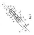
- FIG. 6shows a perspective view of the stop collar of FIG. 1 .
- the stop collar 18is operably configured and dimensioned to cooperate with the shaft 22 and locking collar 20 to set and fix the penetration or effective length 28 of the adjustable length tap assembly 10.
- the stop collar shown in FIG. 6has a nose 58 at the distal end 60, a fore-collar 62 adjacent the nose 58, an abutment ring 64, connecting elements 66 for coupling with the locking collar 20, and a plurality of fingers 68 for engaging with the shaft 20.
- the nose 58may be configured and dimensioned to provide a secure stop for the self-drilling tap 13 and may have an outer dimension close to the dimensions of the shaft to reduce visual obstruction of the tip 13 when the adjustable length tap assembly 10 is positioned for drilling.
- the outer dimension of the stop collarmay then flare outward gradually to a second or intermediate outer-dimension at the fore-collar 62 to provide a surface which may be readily gripped and manipulated by a user.
- the profile of nose 58 and fore-collar 62may be configured and dimensioned to reduce the likelihood of incorrect seating of the adjustable length tap assembly 10 on a drill plate and/or bone.
- the fore-collar 62may further include a transition to a portion having a larger outer dimension which may form an abutment ring 64.
- the abutment ring 64may be operably configured and dimensioned to provide a stop 70 for the locking collar 20, which may be connected to the stop collar 18 by connecting elements 66 located near the abutment ring 64.
- the connecting elements 66comprise external threads which are disposed about the central portion of the stop collar 18 between the abutment ring 64 and a plurality of fingers 68. Coupling elements other than threads may be used to couple the locking collar 20 with the stop collar 18.
- the fingers 68assist in fixing the position of the stop collar and may each generally comprise an elongated member, that is formed by slots 72 in a thin wall section of the stop collar 18.
- the fingers 68are configured and dimensioned to flex.
- the stop collar 18has four fingers 68.
- a stop collar 18 having a configuration with less or more fingers 68might also be used.
- a stop collar having three fingers defined by three slotsmay be used, or a stop collar with five fingers and having five slots may be used.
- the fingers 68may be substantially identical in construction or they may differ one from another.
- the fingers 68may be disposed in a substantially symmetrical configuration or they may be disposed about the stop collar in some other fashion.
- the stop collar 18comprises four substantially identical fingers 68 disposed in a generally symmetrical pattern about the proximal end 74 of the stop collar 18.
- the inner surface 78 of the fingers 68may be smooth and may be configured and dimensioned to bear upon and slide along the shaft 22 of the self-drilling tap 12.
- the fingers 68 of the stop collar 18may also be operably configured and dimensioned to selectively engage and disengage with the grooves 24 of the tap 12. For example, this may be accomplished by a projection, structure or nub 48 located on the inner surface 78 of each finger 68.
- each finger 68may be configured and dimensioned to slidably receive the locking collar 20 over the outer surface 76.
- the outer surfaces 76 of the fingers 68also may be configured and dimensioned to bear against the locking collar 20. This may be accomplished by a structure, as shown in FIGS. 8 and 9 , such as a raised area or seat 80, located on the outer surface 76 of each finger 68.
- a structureas shown in FIGS. 8 and 9 , such as a raised area or seat 80, located on the outer surface 76 of each finger 68.
- the locking collarmay press against the seat 80 and drive the nub 48 into engagement with a groove 24 on the shaft 22 of the self-drilling tap 12.
- the nub 48for example, may be substantially triangular or trapezoidal in section.
- the shape of the nub 48may be designed to securely engage with the groove 24 when locking the penetration or effective length 28 of the adjustable length tap assembly 10.
- the shape of nubmay also be configured to facilitate disengagement of the nub 48 from a groove 24 when unlocking or adjusting the effective length 28 of the adjustable length tap assembly 10.
- the number and geometry of the slots 72may be configured and dimensioned to provide the fingers 68 with special properties.
- a slot 72 comprising an enlarged rounded portion 82 at the basemay be formed to provide special properties to the finger.
- the enlarged rounded portion 82may provide increased flexibility while preventing stress concentrations and fatigue.
- one or more slots 72may be adapted to provide increased resiliency or flex to the fingers 68, making it easier to slide the stop collar 18 along the shaft 22, as the nubs 48 engage and disengage with the grooves 24.
- the stop collar 18may be formed from materials which are bio-compatible, and which are capable of withstanding the required mechanical loading and abrasion.
- the stop collar 18,preferably may be made from materials that are durable and will prevent shearing of the nubs.
- the stop collarmay be made from materials which provide the fingers with added resiliency to movement yet will not readily fatigue or fail during use.
- the stop collar 18preferably may be made from materials which will not fail when placed into abrasive contact with a drill guide plate during use.
- the stop collar 18preferably may be made from any 300 series stainless steel.
- 316 stainless steelmay be used to form the stop collar 18.
- stop collar 18examples include titanium and titanium-alloys.
- the stop collar 18might also be formed from materials which are non-magnetic in order to provide a tap assembly 18 which is suitable for use with an MRI system.
- the stop collarmay also be radiolucent, or portions may be radiolucent.
- the locking collar 20generally comprises a tubular member having a bore 86, which is configured and adapted to engage or mate with the stop collar 18.
- the locking collar 20may control the movement of the tap assembly.
- the cross-section of the locking collar 20 taken in a direction perpendicular to the longitudinal axis 14 of the locking collarmay be substantially uniform.
- the locking collar 20may have a cross section that varies.
- the shape of the exterior surface 84may be constant and the shape and diameter of the interior bore 86 may vary along the length of the locking collar.
- the shape of the exterior surface 84may vary and the bore 86 may remain substantially unchanged along the length of the locking collar 20.
- the locking collaris a generally hollow cylinder.
- the bore 86 of the locking collar 20may be configured and dimensioned to slide along the tap 12 as well as over the fingers 68 of the stop collar 18.
- the cross-section of the bore 86may be circular, polygonal or some other shape.
- the dimensions of the bore 86may vary, and part of the bore 86 may be adapted to connect with the stop collar 18.
- the distal end 88 of the bore 86may comprise internal screw threads 90.
- the bore 86 of the locking collar 20may comprise sections having different dimensions.
- the locking collarmay have a bore 86 comprising multiple sections of progressively smaller dimension.
- the dimensions of the boremay be greater at the distal end 88 than at the proximal end 92 of the locking collar 20, such that the progressive change in dimensions of the bore 86 presses the fingers 68 of the stop collar 18 more firmly into the grooves 24 of the shaft 22 when the locking collar 20 and stop collar 18 are coupled and tightened.
- the exterior surfaces 84 of the locking collar 20may also facilitate quick, reliable and accurate adjustment of the exposed tap length 28.
- the dimension of the exterior surface 84tapers gradually from the distal end to the proximal end.
- the locking collar 20may be thicker at the distal end 88 to accommodate internal coupling elements 90 (for example, internal screw threads) which are adapted to engage or mate with connecting elements 66 (for example, external screw threads) on the stop collar 18.
- the locking collar 20also may be thicker in the distal end 88 to provide a comfortable gripping section 94 so that the locking collar 20 may be reliably held and manipulated.
- the exterior surface 84 of the locking collar 20may further comprise raised areas 96 to enhance the grip and tactile feel of the locking collar 20.
- the raised areas 96may promote the ease and reliability of setting and locking the length 28 of the tap assembly.
- these raised areas 96are in the form of longitudinal ridges that are radially disposed about the outer surface 84 of the locking collar.
- Other grip enhancing configurations on the exterior surface 84might also be envisioned by one of ordinary skill in the art, such as for example, circumferential raised areas or ridges, or combinations of longitudinal and circumferential ridges, or other surface texturing.
- the proximal end 92 of the locking collar 20may have a thinner wall section than at the distal end 88 to enhance visibility through the locking collar 20 when looking at markings on the shaft 22.
- a thinner wall sectionmay also enhance visibility through these areas of the locking collar 20.
- a relatively thin wall section at the distal end 88may also enhance visual clarity along the shaft 22 and through openings or windows that may be formed in the locking collar 20.
- the proximal end 92 (i.e the finger tips) of the locking collar 20may align with the selected length indicator 26 for a desired tap length 28.
- the selected tap length indicator 26 and indica 56may be visible through an opening or window in an opaque locking collar 20.
- the proximal end 92 of the locking collar 20may comprise a clear material, which may be substantially transparent. The visibility provided by such a material may allow a user to see directly through the locking collar 20 and easily view the length indicators 26, indica 56, and the proximal end 92 of the stop collar 18 to visually determine the effective length 28 of the adjustable-length tap assembly.
- the clear materialmay or may not have a tint.
- One clear material from which the locking collar may be madeis plastic.
- the locking collar 20may be configured and dimensioned to be fabricated as a molded piece.
- a locking collar 20 formed from plasticmay have connecting elements 90 (for example, threads) for connecting to the stop collar 18 which may be made from other materials.
- the molded locking collar 20may be made from a medical grade poly-carbonate.
- the locking collarmay be formed from "MAKROLON.”TM
- plastic materials that may be used for forming the locking collar 20should be able to withstand gamma-sterilization during packaging.
- the locking collar 20may also be made from other bio-compatible materials, including the same materials described above in connection with the shaft and stop collar.
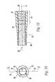
- the locking collar 99may be specially configured and dimensioned to be formed from a metal-alloy such as 316 stainless steel. As shown in FIG. 13 , the locking collar 99 may comprise a cylinder having a bore 100 of varying dimension, which extends from the distal end 101 to the proximal end 102. As shown in FIG. 12 , the locking collar 99 may be capable of sliding completely over the proximal end 103 of the stop collar 104, when coupled to the stop collar, thereby providing an unobstructed view of the length indicators. Thus, the locking collar 99 may or may not have windows or slots to allow a user to read the setting of effective length 28 of the adjustable length tap assembly 98.
- FIG. 14shows an exemplary collection of instruments 104, which may be included in a pre-packaged surgical kit 106 (shown in FIG. 15 ) for forming an adjustable length tap assembly 12 that may be used to drill and tap bores in bone.
- the instruments 104preferably may include a stop collar 18, a locking collar 20, and more than one tap 12.
- the collection of instruments 104preferably may also include a handle (not shown) for releasably securing to each tap 12, so that a user may manually drill and tap bores in bone.
- three taps 12are included in the collection 104.
- the taps 12preferably may be used interchangeably with the stop collar 18 and the locking collar 20.
- the taps 12preferably may also have identical shaft 22 and groove configurations 24.
- the taps 12may further have cutting threads 16 that are adapted for screws of a similar type but of different diameter.
- the tapsmay have cutting threads 16 of substantially identical size and shape, or the cutting threads 16 adapted for different types of screws.
- a wide variety of various instrumentsmay be contained in the kit 106.
- a first kitmay package a collection of instruments adapted for a particular mandible procedure
- a second kitcan package a collection of instruments adapted for a particular pelvic procedure
- a third kitmay package a collection of instruments for a particular orthopedic procedure.
- FIGS. 14 and 15illustrate one of many different possible embodiments for the instrument collection 104 and kit housing 106.
- the kit 106includes an interior tray 108 made, e.g., from die cut cardboard, plastic sheet, or thermo-formed plastic material.
- the tray 108may include spaced apart tabs or the like (not shown), which may hold the various instruments 104 in a secure position during sterilization and storage prior to use.
- the kit 106may include an inner wrap 110, which is peripherally sealed by heat or the like, to enclose the tray 108 from contact with the outside environment.
- One end of the inner wrapmay include a conventional peal-away seal 112, to provide quick access to the tray 108 at the instant of use, which preferably occurs in a sterile environment, such as within an operating room.
- the kit 106may also include an outer wrap 114, which is also peripherally sealed by heat or the like, to enclosed the inner wrap 110.
- One end of the outer wrapmay also include a conventional peal-away seal 116, to provide access to the inner wrap 110 and its contents.
- the outer wrap 114can be removed from the inner wrap in anticipation of imminent use, without compromising sterility of the contents of the kit 106.
- Each inner and outer wrap 110 and 114may include a peripherally sealed top sheet 118 and bottom sheet (not shown).
- the top sheet 118preferably may be made of transparent plastic film, like polyethylene or MYLAR.TM material, to allow visual identification of the contents of the kit 106.
- the bottom sheetmay be made from a material that is permeable to ETO sterilization gas, such as, for example, TYVEKTM plastic material.
- the kit 106may also include in the tray 108 directions 120 for using the contents of the kit 106 to carry out a desired procedure. An exemplary procedure which the directions 120 can describe will be explained later.
- the directions 120may also include a statement, for example, "For Single Patient Use Only" (or comparable language) to affirmatively caution against reuse of the contents of the kit 106 whose performance characteristics and efficacy may degrade after use.
- the adjustable length tap assembly 20, for these reasons,may be used but for a single surgical procedure and then discarded.
- the directions 120may also affirmatively instruct against resterilization of a portion or all of the contents of the kit 106, and also may instruct the physician to dispose of at least these contents of the kit 106 upon use in accordance with applicable biological waste procedures.
- the presence of the collection of instruments 104 packaged in the sterile kit 106may verify to the physician that the contents are sterile and have not been subjected to prior use. The physician may thereby be assured that the instruments 104 meet established performance and sterility specifications.
- the locking collar 20slips over the stop collar 18 and tap 12 and when tightened to the stop collar 18, locks the assembly 10.
- the lockingmay be accomplished by nubs 48 on the fingers 68 of the stop collar 18 being driven into grooves 24 on the shaft 22.
- the proximal edge of the fingers (i.e., the finger tips) 88may align with the length indicator 26 on the tap shaft 12 that corresponds with the groove 24 the nubs 48 engage.
- the stop collar 18 and the locking collar 20When loosely engaged the stop collar 18 and the locking collar 20 may be moved in unison along the shaft 22 in a ratchet like fashion.
- the fingers 68 of the stop collar18have a raised area 80 on the outer surface 76 to cause the nub 48 on the inner surface 78 to be pushed firmly into engagement with the groove 24.
- the stop collar 18 and locking collar 20preferably are capable of resisting, without axial movement, an axial force of at least about 300 N, when the adjustable length tap assembly is locked.
- the adjustable length tap assembly 10is directed toward a method for drilling and tapping holes in bone.
- a userselects a tap 12 for preparing a bore which is adapted for a particular screw configuration. The selection may be based, for instance, on the screw diameter, or the part number of the screw.
- a stop collar 18then may be mounted about the tap 12 along a shaft 22, with the proximal ends 54 of the fingers 68 pointing toward the proximal end 31 of the shaft 22.
- a locking collar 20may then be positioned on the shaft 22 of the tap 12 so that it is capable of coupling with the stop collar 18. The stop collar 18 and the locking collar 22 are then joined together.
- the tightness of the connection between the stop collar 18 and the locking collar 20may then be adjusted to provide a desired resistance to movement between the stop collar-locking collar combination and the tap 12.
- the position of the stop collar 18may then be adjusted to a desired tap length 28 setting by aligning the proximal ends 74 of the stop collar with the desired length indicator 26.
- the numeral 5may designate the appropriate length indicator 26 for a particular screw with a length of 5 mm.
- the connection between the stop collar 18 and the locking collar 20may then be tightened to secure the selected length 28 of the tap assembly.
- the position of the stop collarmay be positioned to provide a desired tap length.
- the stop collar 18may be advanced to set the desired position and the locking collar then positioned on the shaft, coupled to the stop collar, and adjusted to lock the stop collar and locking collar assembly in place on the shaft.
- the proximal end 31 of the self-drilling tap 12may then be inserted in to a drill (not shown), such as a battery powered reversible drill.
- a drillsuch as a battery powered reversible drill.
- the tip 13 of the self-drilling tap 12may be seated in a guide plate and placed into contact with bone.
- the drillmay then be used to rotate the adjustable length tap assembly 10 to bore and tap a hole of predetermined dimension into the bone. The maximum depth of the bore may be reached when the nose 58 of the stop collar contacts the guide plate.
- the adjustable length tap assembly 10may then be withdrawn from the bore and the guide plate, and a screw advanced and secured in the tapped bore.
- the locking mechanism of the assembly 10allows the stop collar 18 and locking collar 20 to rotate with respect to the tap 12, particularly after the stop collar 18 hits the drill guide plate without affecting the previously adjusted length setting 28. Because the nub 48 is firmly seated in the groove 24, the length of the tap 28 may not change, however, the stop collar 18 and locking collar 20 are free to rotate about the shaft 22. This may facilitate accuracy in the advancement of bores having a pre-selected depth. For instance, if relative rotation between the stop collar 20 and the shaft could change the length of the exposed cutting threads 28, each time the stop collar hits the drill guide plate the resulting movement between the shaft and the stop collar might potentially cause the tap 12 to change length 28.
- the boremight proceed undesirably through the bone and into adjacent tissue.
- the exposed length of the cutting threads 28was decreased, a screw advancing into untaped bone might damage or crack the bone or in the case of resorbable screws, damage may occur to the screw.
- the tap assemblymay also provide useful tactile feed back to the user, due to the ratchet effect of the nubs 48 engaging and disengaging with the grooves 24 as the stop collar 18 and locking collar 28 are moved along the shaft 22.
- a usermay feel and hear the number of clicks as the nubs disengage and engage grooves as the stop collar translates along the shaft from a first known tap length setting to a desired second tap length setting, thereby increasing the speed of tap adjustments during a procedure.
- the ratchet effect of the locking mechanismmay provide an additional check for assuring the proper length is selected as the user need not rely on a purely visual system to select or check the length adjustment of the tap assembly.
- adjustable length tap assemblyhas been described with reference to certain preferred embodiments, it should be kept in mind that the scope of the present invention is not limited to these embodiments.
- the adjustable length tap assemblymay be modified or extended to accommodate particular formulations of construction materials or fabrication techniques which may require different connecting elements.
- the number and spacing of the grooves on the shaftmay be changed to accommodate different screw lengths.
- different materials and surface coatings, or outer layers of different materialsmay be applied to the adjustable length tap assembly.
Landscapes
- Health & Medical Sciences (AREA)
- Life Sciences & Earth Sciences (AREA)
- Surgery (AREA)
- Molecular Biology (AREA)
- General Health & Medical Sciences (AREA)
- Biomedical Technology (AREA)
- Heart & Thoracic Surgery (AREA)
- Medical Informatics (AREA)
- Nuclear Medicine, Radiotherapy & Molecular Imaging (AREA)
- Animal Behavior & Ethology (AREA)
- Engineering & Computer Science (AREA)
- Public Health (AREA)
- Veterinary Medicine (AREA)
- Dentistry (AREA)
- Oral & Maxillofacial Surgery (AREA)
- Orthopedic Medicine & Surgery (AREA)
- Surgical Instruments (AREA)
Description
- The present invention is directed to a self-drilling tap for use in orthopaedic procedures to treat bone, and in particular to a device for drilling and tapping holes in bone to accommodate screws used in cranio-facial, mandible, pelvic and other orthopaedic procedures.
- Drilling in bones, particularly bones of the face and head, requires accurate and reliable control over the penetration depth. For instance, over drilling and tapping a bore may damage the brain or other underlying soft tissue. To reduce this risk, self-drilling taps for use in cranio-facial procedures generally have a fixed depth.
- U.S. Patent No.
US 4,341,206 discloses a tool for forming a stepped blind hole in bone for receipt of a fracture reducing and stabilizing surgical implant. The tool comprises a small diameter drill portion axially adjustable with respect to a larger diameter reamer portion. A conical portion includes cutting surfaces to chamfer the entrance of the hole and also includes non-cutting portions which serve to limit penetration of the tool into the bone. The tool is cannulated to allow its use in conjunction with a previously installed Kirschner guide wire.DE 38 00 482 A1DE 3622 676 A1 also disclose an adjustable length tap assembly. - There exists a need for a self-drilling tap having an adjustable length, which may accurately and reliably replace several taps of various fixed lengths.
- The present invention is directed to a tap assembly according to claim 1 which may be adjusted by a user to drill and tap holes in bone in order to accommodate screws of various lengths. The adjustable length tap comprises a shaft, a stop collar and a locking collar which cooperate to expose and set an effective length of cutting thread located on the tip of the shaft.
- The shaft has a longitudinal axis, a proximal end, and a distal end with cutting threads for drilling and tapping holes in bone. The adjustable length assembly also includes stop collar having proximal and distal ends. The distal end of the stop collar is configured and dimensioned to provide a stop for the self-drilling tap. The stop collar is configured and dimensioned to be translatable along the longitudinal axis of the shaft and to contact against a surface to block advancement of the tap at a maximum depth of the threaded hole. The shaft preferably includes length indicator marks, the length indicator marks being configured and dimensioned to allow for a controlled setting of the effective length of the adjustable length tap assembly. Each length indicator mark is preferably configured and dimensioned to correspond with one effective length. In addition, each length indicator mark is preferably configured and dimensioned to be visibly aligned with the proximal end of the stop collar, when the effective length is set. In an exemplary embodiment, each length indicator mark is selectively disposed on the shaft, and each length indicator mark is visibly identified by indicia. The shaft is preferably made from bio-compatible materials and may be made from non-magnetic materials.
- The stop collar has a body having an inner surface and an outer surface. A portion of the inner surface is configured and dimensioned to engage with the shaft in at least one predetermined location. The stop collar preferably has one or more fingers, and the shaft preferably has one or more grooves. In addition, the one or more fingers may have inner and outer surfaces and at least one projection or nub formed on the inner surface. The projection preferably is configured and dimensioned to interact with the grooves to prevent translational movement of the stop collar along the longitudinal axis of the shaft. The one or more fingers preferably is formed by at least two slots. Each of the two slots preferably extend from the outer surface of the stop collar to the inner surface of the stop collar. Preferably, the stop collar has at least two fingers, the fingers being substantially identical and arranged in a substantially symmetrical configuration about a central axis of the stop collar.
- In an illustrative embodiment, the at least one projection on the stop collar has a mid-point, and the at least one groove on the shaft has a mid-point. A first distance measured from the mid-point of the at least one projection to the proximal end of the stop collar preferably is related to a second distance measured from the mid-point of the at least one groove to a corresponding length indicator mark on the shaft. The first distance preferably is substantially equal to the second distance. The grooves preferably extend continuously about the shaft, and the grooves preferably are oriented substantially perpendicular to the longitudinal axis of the shaft. In an exemplary embodiment, the grooves are substantially equidistant from one another. The grooves may also be substantially identical in size and shape.
- The adjustable length tap assembly also comprises a locking collar. The locking collar is configured and dimensioned to be received over at least a portion of the stop collar. The locking collar is configured and dimensioned to engage with the stop collar to set the effective length of the cutting threads, and to prevent movement of the stop collar along the longitudinal axis of the shaft. The locking collar, also, is preferably configured and dimensioned to bear against a structure on the outer surface of the one or more fingers to releasably engage the at least one nub with a groove on the shaft. The locking collar preferably comprises a tubular member having a bore, and the proximal end of the locking collar preferably is capable of translating over the proximal end of the stop collar. In an exemplary embodiment, at least a part of the locking collar is transparent, and the locking collar preferably is formed from a medical grade polycarbonate.
- In use, the locking collar and the stop collar engage or mate with each other in at least two configurations, a first configuration which allows translational movement of the stop collar and locking collar together along the shaft, and a second configuration that prevents translational movement of the stop collar along the longitudinal axis of the shaft. The stop collar and locking collar, generally, are free to rotate about the shaft when the stop collar and locking collar engage in the second configuration.
- The present invention is also directed to a surgical kit comprising the tap assembly of claim 1 for drilling and tapping holes in bone. The kit comprises additional shafts each having a longitudinal axis, a proximal end and a distal end. At least a portion of each shaft should have cutting threads for drilling and tapping bores in bone. The kit may also include a stop collar having proximal and distal ends, which preferably is configured and dimensioned to be translatable along the longitudinal axis of each of the shafts. The stop collar preferably has a body having an inner surface and an outer surface, at least a portion of the inner surface being configured and dimensioned to engage with the at least one shaft in at least one predetermined location. Additionally, the kit may further include a locking collar comprising a member configured and dimensioned to be received over at least a portion of the stop collar. The locking collar preferably is configured and dimensioned to engage or mate with the stop collar to set at least one effective length for the cutting threads and preferably to prevent movement of the stop collar along the longitudinal axis of the at least one shaft.
- Preferred features of the present invention are disclosed in the accompanying drawings, wherein similar reference characters denote similar elements throughout the several views, and wherein:
FIG. 1 shows a perspective view of an exemplary embodiment of the adjustable length tap assembly;FIG. 2 shows a partial cross-sectional view alongline 2--2 ofFIG. 1 ;FIG. 3 shows a plan view of the shaft of the tap assembly ofFIG. 2 ;FIG. 4 shows a partial plan view of the reverse side of the shaft ofFIG. 3 ;FIG. 5 shows an enlarged view of grooves and markings on the shaft ofFIG. 3 ;FIG. 6 shows a perspective view of the stop collar of the tap assembly ofFIG. 1 ;FIG. 7 shows a cross-sectional view along line 7--7 ofFIG. 6 ;FIG. 8 shows an enlarged plan view of a slot of the stop collar ofFIG. 6 ;FIG. 9 shows an enlarged view of a nub and seating projection on the stop collar ofFIG. 6 ;FIG. 10 shows a front elevation of the locking collar shown inFIG. 1 ;FIG. 11 shows a cross-sectional view alongline 11--11 ofFIG. 10 ;FIG. 12 shows a partial cross-sectional view along the longitudinal axis of another embodiment of the tap assembly ofFIG. 1 ;FIG. 13 shows a cross-sectional view of the locking collar along the longitudinal axis of the tap assembly ofFIG. 12 ;FIG. 14 is a perspective view of an exemplary collection of instruments, which in use, may form an adjustable length tap assembly ofFIG. 1 ; andFIG. 15 is a plan view of an illustrative kit housing the collection of instruments ofFIG. 14 .- In the description that follows, any reference to either orientation or direction is intended primarily for the convenience of description and is not intended in any way to limit the scope of the present invention thereto.
FIG. 1 shows anassembly 10 for use in drilling and tapping holes in bone. Theassembly 10 comprises a self-drilling tap 12 having alongitudinal axis 14, astop collar 18, and alocking collar 20. The self-drilling tap 12 may have adistal end 13 with cuttingthreads 16 adapted to drill and tap holes in bone. Thestop collar 18 and lockingcollar 20 may be moved along the self-drilling tap 12 to expose a portion of the cuttingthreads 16. The relative position ofstop collar 18 and lockingcollar 20 may be fixed along thelongitudinal axis 14 of the self-drilling tap 12. Thestop collar 18 and the lockingcollar 20 may be free to rotate about thelongitudinal axis 14 of the self-drilling tap, even though translational movement along thelongitudinal axis 14 is prevented. Theassembly 10 may be used with other instruments such as a handle and guide plate (not shown) to drill and tap holes in bone. Detachable handles, guide plates, and drills are representative of the instruments and other devices that may be used in conjunction with the adjustable length tap assembly. These instruments, however, may not always be required or may be replaced by different devices that perform similar, additional, or different functions.FIG. 2 shows a cut away view of the adjustable length tap assembly. Thestop collar 18 and the lockingcollar 20 are shown in cross-section, and theshaft 22 is shown in plan view. As shown inFIG. 2 , the self-drilling tap 12 includes ashaft 22 having a tip ordistal end 13 with cuttingthreads 16. Thetap 12 further comprises a plurality ofcircumferential grooves 24,indica 26, such as for example lines, for marking theeffective length 28 of the exposed portion of the cuttingthreads 16, and acoupling element 30 for connecting the self-drilling tap 12 to a handle or a drill (not shown) at theproximal end 31 thereof.- The maximum
outer diameter 32 of the cuttingthreads 16 and thelength 34 of thetip 13, which contains the cutting threads, may be fixed. The dimensions of thetip 13, for anyparticular tap 12, may be based on the size and length of the screw for to be inserted in the bore. The dimensions of thetip 13 may further be adapted to accommodate the thickness of a guide plate. For instance, a special screw may be developed for use in a pelvic procedure, for example, and the dimensions of thetip 13 of the self-drilling tap 12 may be designed to accommodate that screw. For example, one screw type may have an outer diameter of 1.5 mm and a length of 3 mm, and the dimension of thetip 13 may be configured and dimensioned to create a tapped bore that is adapted for screws of that type. Other non-limiting examples of screws, for which the self-drilling tap 12 may be dimensioned, include screws having an outer diameter from about 2.0 mm to about 4.0 mm and having a length from about 3.0 mm to about 8.0 mm. As one skilled in the art would readily appreciate, a self-drilling tap may also be developed for larger or smaller screws. - The cutting
threads 16 may be particularly adapted to cut and remove bone without damaging adjacent tissue. The threads may include sharp cutting flutes 36 and one or morestraight flutes 38 for removing bone chips and cuttings from the bore. For example, two straight flutes aligned 180° from each other may be disposed on the tip. One of ordinary skill in the art would readily appreciate that the number and configuration of cuttingflutes 36 andstraight flutes 38 may be widely varied, or in addition to or alternatively a wide variety of other configurations and combinations may be used. - The
shaft 22 of thetap 12, preferably, may have anouter diameter 40 that is operably configured and dimensioned to slidably receive thestop collar 18 and the lockingcollar 20. A set of taps which may be adapted for screws having differing predetermined diameters and lengths, preferably may each have ashaft 22 ofsame diameter 40. In an exemplary embodiment, theouter diameter 40 of theshaft 22 may be about 3.0 mm. As one skilled in the art would readily appreciate, a set of self-drilling taps having different tip configurations may be supplied as a kit for use with onestop collar 18 and onelocking collar 20. More than onestop collar 18 and more than one locking collar may also be supplied in the kit. For example, a set oftaps 12 having a different outer diameter may be supplied which would be used with different stop and locking collar combinations. - Referring to
FIGS. 3-5 , theshaft 22 may further comprise two ormore grooves 24. Thegrooves 24 may be spaced from thetip 13 on the middle portion of thetap 12. Eachgroove 24 may or may not extend continuously about theshaft 22. In an illustrative embodiment of a self-drilling tap 12 there may be sixgrooves 24 spaced equidistant from one another and oriented perpendicular to the longitudinal axis of theshaft 22. As shown inFIG. 5 , the radius 42 (i.e, the distance equal to one-half the groove width 44) of eachgroove 24 preferably may be substantially constant. In addition, each groove preferably may have substantially thesame radius 42. Similarly, the diameter 46 of thegrooves 24 may vary, but in a preferred embodiment are the same. Theradius 42 and diameter 46 of eachgroove 24 may be operably configured and dimensioned to cooperate with at least one detent ornub 48 on thestop collar 18, as shown inFIG. 2 . Engagement of a nub orprojection 48 with agroove 24 may be used to set the position of the stop collar along the length of theshaft 22 and thus set the penetration oreffective length 28 of theadjustable tap assembly 10. As described in further detail below, a user may selectively press the nubs of thestop collar 18 into agroove 24 on the shaft to lock the penetration oreffective length 28 of the adjustable tap assembly. - As shown in
FIG. 5 , atap 12 having ashaft 22, for example, with anouter diameter 40 of about 3.0 mm may havegrooves 24 having a diameter 46 of about 2.6 mm and aradius 42 of about 0.3 mm. Eachgroove 24 may be spaced one from another at a fixed interval, for example, 1.0 mm on center. As one skilled in the art would readily appreciate, other groove configurations may be desirable. In general, however, a set of self-drilling taps adapted for screws of different diameters, as previously described, may have substantially identical grooves and groove patterns so as to provide the user of the tool with a uniform feel when setting the penetration oreffective length 28 of theadjustable tap assembly 10. A standard feel for setting theeffective length 28 of theadjustable tap assembly 10 may promote ease, reliability, and accuracy in the selection of a desiredeffective tap length 28 during a surgical procedure. Indica 26 or length indicators may be marked on theshaft 22 perpendicular to thelongitudinal axis 14 of the self-drilling tap 12. In general, onelength indicator 26 may be marked on theshaft 22 for eachgroove 24. Eachlength indicator 26 may indicate the length of the screw for which a bore is to be drilled. Alternatively, thelength indicator 26 may correspond to some other designation for a particular screw type. In general, the distance between the mid-point of onegroove 24 and acorresponding length indicator 26 may correspond with the dimensions of thestop collar 18 to allow for the controlled and accurate setting of apredetermined tap length 28. For example, thedistance 52 between the mid-point of agroove 24 and acorresponding length indicator 26, may be the same length as the distance 73, shown inFIG. 7 , which is measured between the mid-point of thenub 48 and theend 54 of the stop collar.- Referring back to
FIGS. 2-5 ,length indicators 26 may be selectively marked on theshaft 22. For instance, the length indicators for screws having odd number designations may be marked on one side of the shaft, and length indicators for screws having even number designations may be marked on the other side of the shaft. Such a marking pattern may facilitate the selection of a desiredeffective length 28 by making it easier to identify, select, and confirm the adjustment. Moreover, eachlength indicator 26 may be identified by indica 56 which uniquely signify eachpossible tap length 28 selection. For instance, theindica 56 may comprise numerals which relate to the length or type of screw for which a bore is to be drilled and tapped. In an illustrative configuration, theindica 56 may be numerals which are bisected by the associatedlength indicators 26. This configuration may provide for larger numerals and clearer identification of the associated length indicator.Markings - The self-
drilling tap 12 may be adapted for use with an integrally formed handle (not shown). Alternatively, the proximal end of the self-drilling tap 31 may be adapted for connection to a removable handle or drill (not shown). For instance, the self-drilling tap 12 may have a hex coupling for connecting to a handle for use as a manually operated instrument. Thetap 12 might also be adapted for quick coupling to a drill. In general, the tap may be made from materials which are bio-compatible and possess relatively high mechanical durability. For example, the tap may be integrally formed from a blank made from stainless steel. In a preferred embodiment, the tap may be made from 440 A stainless steel. The tap may also be made from non-magnetic materials so that it may be suitable for use with an MRI system. The tap may also be radiolucent, or portions may be radiolucent. FIG. 6 shows a perspective view of the stop collar ofFIG. 1 . As previously described, thestop collar 18 is operably configured and dimensioned to cooperate with theshaft 22 and lockingcollar 20 to set and fix the penetration oreffective length 28 of the adjustablelength tap assembly 10. The stop collar shown inFIG. 6 has anose 58 at the distal end 60, a fore-collar 62 adjacent thenose 58, anabutment ring 64, connectingelements 66 for coupling with the lockingcollar 20, and a plurality offingers 68 for engaging with theshaft 20.- The
nose 58 may be configured and dimensioned to provide a secure stop for the self-drilling tap 13 and may have an outer dimension close to the dimensions of the shaft to reduce visual obstruction of thetip 13 when the adjustablelength tap assembly 10 is positioned for drilling. The outer dimension of the stop collar may then flare outward gradually to a second or intermediate outer-dimension at the fore-collar 62 to provide a surface which may be readily gripped and manipulated by a user. Thus, the profile ofnose 58 and fore-collar 62 may be configured and dimensioned to reduce the likelihood of incorrect seating of the adjustablelength tap assembly 10 on a drill plate and/or bone. - The fore-
collar 62 may further include a transition to a portion having a larger outer dimension which may form anabutment ring 64. Theabutment ring 64 may be operably configured and dimensioned to provide a stop 70 for the lockingcollar 20, which may be connected to thestop collar 18 by connectingelements 66 located near theabutment ring 64. InFIG. 6 , the connectingelements 66 comprise external threads which are disposed about the central portion of thestop collar 18 between theabutment ring 64 and a plurality offingers 68. Coupling elements other than threads may be used to couple the lockingcollar 20 with thestop collar 18. - The
fingers 68 assist in fixing the position of the stop collar and may each generally comprise an elongated member, that is formed byslots 72 in a thin wall section of thestop collar 18. Thefingers 68 are configured and dimensioned to flex. InFIG. 6 , thestop collar 18 has fourfingers 68. As one of skill in the art might appreciate, astop collar 18 having a configuration with less ormore fingers 68 might also be used. For example, a stop collar having three fingers defined by three slots may be used, or a stop collar with five fingers and having five slots may be used. Thefingers 68 may be substantially identical in construction or they may differ one from another. Similarly, thefingers 68 may be disposed in a substantially symmetrical configuration or they may be disposed about the stop collar in some other fashion. For instance, in the embodiment shown inFIGS. 6-9 , thestop collar 18 comprises four substantiallyidentical fingers 68 disposed in a generally symmetrical pattern about theproximal end 74 of thestop collar 18. - As shown in
FIGS. 7 and9 , theinner surface 78 of thefingers 68 may be smooth and may be configured and dimensioned to bear upon and slide along theshaft 22 of the self-drilling tap 12. Thefingers 68 of thestop collar 18 may also be operably configured and dimensioned to selectively engage and disengage with thegrooves 24 of thetap 12. For example, this may be accomplished by a projection, structure ornub 48 located on theinner surface 78 of eachfinger 68. - The
outer surface 76 of eachfinger 68 may be configured and dimensioned to slidably receive thelocking collar 20 over theouter surface 76. Theouter surfaces 76 of thefingers 68 also may be configured and dimensioned to bear against the lockingcollar 20. This may be accomplished by a structure, as shown inFIGS. 8 and 9 , such as a raised area orseat 80, located on theouter surface 76 of eachfinger 68. In general, as the lockingcollar 20 is advanced over thestop collar 18, the locking collar may press against theseat 80 and drive thenub 48 into engagement with agroove 24 on theshaft 22 of the self-drilling tap 12. Thenub 48, for example, may be substantially triangular or trapezoidal in section. The shape of thenub 48 may be designed to securely engage with thegroove 24 when locking the penetration oreffective length 28 of the adjustablelength tap assembly 10. The shape of nub may also be configured to facilitate disengagement of the nub 48 from agroove 24 when unlocking or adjusting theeffective length 28 of the adjustablelength tap assembly 10. - Referring to
FIG. 8 , the number and geometry of theslots 72 may be configured and dimensioned to provide thefingers 68 with special properties. For instance, aslot 72 comprising an enlargedrounded portion 82 at the base may be formed to provide special properties to the finger. The enlargedrounded portion 82 may provide increased flexibility while preventing stress concentrations and fatigue. Also, one ormore slots 72 may be adapted to provide increased resiliency or flex to thefingers 68, making it easier to slide thestop collar 18 along theshaft 22, as thenubs 48 engage and disengage with thegrooves 24. - The
stop collar 18 may be formed from materials which are bio-compatible, and which are capable of withstanding the required mechanical loading and abrasion. For example, thestop collar 18, preferably may be made from materials that are durable and will prevent shearing of the nubs. In addition, the stop collar may be made from materials which provide the fingers with added resiliency to movement yet will not readily fatigue or fail during use. In addition, thestop collar 18 preferably may be made from materials which will not fail when placed into abrasive contact with a drill guide plate during use. Thus, for example, thestop collar 18 preferably may be made from any 300 series stainless steel. Preferably, 316 stainless steel may be used to form thestop collar 18. Other non-limiting examples of materials from which the stop collar may be formed in include titanium and titanium-alloys. Thestop collar 18 might also be formed from materials which are non-magnetic in order to provide atap assembly 18 which is suitable for use with an MRI system. The stop collar may also be radiolucent, or portions may be radiolucent. - Referring to
FIGS. 10 and 11 , the lockingcollar 20 generally comprises a tubular member having abore 86, which is configured and adapted to engage or mate with thestop collar 18. The lockingcollar 20 may control the movement of the tap assembly. The cross-section of the lockingcollar 20 taken in a direction perpendicular to thelongitudinal axis 14 of the locking collar may be substantially uniform. Alternatively, the lockingcollar 20 may have a cross section that varies. For example, the shape of theexterior surface 84 may be constant and the shape and diameter of the interior bore 86 may vary along the length of the locking collar. In another example, the shape of theexterior surface 84 may vary and thebore 86 may remain substantially unchanged along the length of the lockingcollar 20. In the embodiment shown inFIGS. 10 and 11 , the locking collar is a generally hollow cylinder. - In general, the
bore 86 of the lockingcollar 20 may be configured and dimensioned to slide along thetap 12 as well as over thefingers 68 of thestop collar 18. The cross-section of thebore 86 may be circular, polygonal or some other shape. In addition, the dimensions of thebore 86 may vary, and part of thebore 86 may be adapted to connect with thestop collar 18. For example, thedistal end 88 of thebore 86 may compriseinternal screw threads 90. Additionally, thebore 86 of the lockingcollar 20 may comprise sections having different dimensions. In particular, the locking collar may have abore 86 comprising multiple sections of progressively smaller dimension. For instance, the dimensions of the bore may be greater at thedistal end 88 than at theproximal end 92 of the lockingcollar 20, such that the progressive change in dimensions of thebore 86 presses thefingers 68 of thestop collar 18 more firmly into thegrooves 24 of theshaft 22 when the lockingcollar 20 and stopcollar 18 are coupled and tightened. - The exterior surfaces 84 of the locking
collar 20 may also facilitate quick, reliable and accurate adjustment of the exposedtap length 28. In the embodiment ofFIGS. 10 and 11 , the dimension of theexterior surface 84 tapers gradually from the distal end to the proximal end. The lockingcollar 20 may be thicker at thedistal end 88 to accommodate internal coupling elements 90 (for example, internal screw threads) which are adapted to engage or mate with connecting elements 66 (for example, external screw threads) on thestop collar 18. The lockingcollar 20 also may be thicker in thedistal end 88 to provide a comfortable grippingsection 94 so that the lockingcollar 20 may be reliably held and manipulated. - The
exterior surface 84 of the lockingcollar 20 may further comprise raisedareas 96 to enhance the grip and tactile feel of the lockingcollar 20. In addition, the raisedareas 96 may promote the ease and reliability of setting and locking thelength 28 of the tap assembly. InFIGS. 10 and 11 , these raisedareas 96 are in the form of longitudinal ridges that are radially disposed about theouter surface 84 of the locking collar. Other grip enhancing configurations on theexterior surface 84 might also be envisioned by one of ordinary skill in the art, such as for example, circumferential raised areas or ridges, or combinations of longitudinal and circumferential ridges, or other surface texturing. - The
proximal end 92 of the lockingcollar 20 may have a thinner wall section than at thedistal end 88 to enhance visibility through the lockingcollar 20 when looking at markings on theshaft 22. A thinner wall section may also enhance visibility through these areas of the lockingcollar 20. A relatively thin wall section at thedistal end 88 may also enhance visual clarity along theshaft 22 and through openings or windows that may be formed in thelocking collar 20. For instance, the proximal end 92 (i.e the finger tips) of the lockingcollar 20 may align with the selectedlength indicator 26 for a desiredtap length 28. In another example, the selectedtap length indicator 26 andindica 56 may be visible through an opening or window in anopaque locking collar 20. - In
FIGS. 10 and 11 , theproximal end 92 of the lockingcollar 20 may comprise a clear material, which may be substantially transparent. The visibility provided by such a material may allow a user to see directly through the lockingcollar 20 and easily view thelength indicators 26,indica 56, and theproximal end 92 of thestop collar 18 to visually determine theeffective length 28 of the adjustable-length tap assembly. The clear material may or may not have a tint. One clear material from which the locking collar may be made is plastic. In particular, the lockingcollar 20 may be configured and dimensioned to be fabricated as a molded piece. A lockingcollar 20 formed from plastic may have connecting elements 90 (for example, threads) for connecting to thestop collar 18 which may be made from other materials. In a preferred embodiment, the moldedlocking collar 20 may be made from a medical grade poly-carbonate. For example, the locking collar may be formed from "MAKROLON."™ In general, plastic materials that may be used for forming the lockingcollar 20 should be able to withstand gamma-sterilization during packaging. The lockingcollar 20 may also be made from other bio-compatible materials, including the same materials described above in connection with the shaft and stop collar. - Referring to
FIGS. 12 and13 , in another embodiment of the adjustablelength tap assembly 98, the lockingcollar 99 may be specially configured and dimensioned to be formed from a metal-alloy such as 316 stainless steel. As shown inFIG. 13 , the lockingcollar 99 may comprise a cylinder having abore 100 of varying dimension, which extends from thedistal end 101 to theproximal end 102. As shown inFIG. 12 , the lockingcollar 99 may be capable of sliding completely over theproximal end 103 of thestop collar 104, when coupled to the stop collar, thereby providing an unobstructed view of the length indicators. Thus, the lockingcollar 99 may or may not have windows or slots to allow a user to read the setting ofeffective length 28 of the adjustablelength tap assembly 98. FIG. 14 shows an exemplary collection ofinstruments 104, which may be included in a pre-packaged surgical kit 106 (shown inFIG. 15 ) for forming an adjustablelength tap assembly 12 that may be used to drill and tap bores in bone. Theinstruments 104 preferably may include astop collar 18, a lockingcollar 20, and more than onetap 12. The collection ofinstruments 104 preferably may also include a handle (not shown) for releasably securing to eachtap 12, so that a user may manually drill and tap bores in bone. In the illustrative embodiment shown inFIG. 14 , three taps 12 are included in thecollection 104. The taps 12 preferably may be used interchangeably with thestop collar 18 and the lockingcollar 20. The taps 12 preferably may also haveidentical shaft 22 andgroove configurations 24. The taps 12 may further have cuttingthreads 16 that are adapted for screws of a similar type but of different diameter. Alternatively, the taps may have cuttingthreads 16 of substantially identical size and shape, or the cuttingthreads 16 adapted for different types of screws. It should be appreciated that a wide variety of various instruments may be contained in thekit 106. For example, a first kit may package a collection of instruments adapted for a particular mandible procedure, a second kit can package a collection of instruments adapted for a particular pelvic procedure, and a third kit may package a collection of instruments for a particular orthopedic procedure.FIGS. 14 and15 illustrate one of many different possible embodiments for theinstrument collection 104 andkit housing 106.- Referring to
FIG. 15 , in the illustrated embodiment, thekit 106 includes aninterior tray 108 made, e.g., from die cut cardboard, plastic sheet, or thermo-formed plastic material. Thetray 108 may include spaced apart tabs or the like (not shown), which may hold thevarious instruments 104 in a secure position during sterilization and storage prior to use. When packaged as a sterile assembly, thekit 106 may include aninner wrap 110, which is peripherally sealed by heat or the like, to enclose thetray 108 from contact with the outside environment. One end of the inner wrap may include a conventional peal-away seal 112, to provide quick access to thetray 108 at the instant of use, which preferably occurs in a sterile environment, such as within an operating room. When packaged as a sterile assembly, thekit 106 may also include anouter wrap 114, which is also peripherally sealed by heat or the like, to enclosed theinner wrap 110. One end of the outer wrap may also include a conventional peal-away seal 116, to provide access to theinner wrap 110 and its contents. Theouter wrap 114 can be removed from the inner wrap in anticipation of imminent use, without compromising sterility of the contents of thekit 106. - Each inner and
outer wrap kit 106. The bottom sheet may be made from a material that is permeable to ETO sterilization gas, such as, for example, TYVEK™ plastic material. Thekit 106 may also include in thetray 108directions 120 for using the contents of thekit 106 to carry out a desired procedure. An exemplary procedure which thedirections 120 can describe will be explained later. When packaged as a sterile assembly, thedirections 120 may also include a statement, for example, "For Single Patient Use Only" (or comparable language) to affirmatively caution against reuse of the contents of thekit 106 whose performance characteristics and efficacy may degrade after use. The adjustablelength tap assembly 20, for these reasons, may be used but for a single surgical procedure and then discarded. Thedirections 120 may also affirmatively instruct against resterilization of a portion or all of the contents of thekit 106, and also may instruct the physician to dispose of at least these contents of thekit 106 upon use in accordance with applicable biological waste procedures. The presence of the collection ofinstruments 104 packaged in thesterile kit 106 may verify to the physician that the contents are sterile and have not been subjected to prior use. The physician may thereby be assured that theinstruments 104 meet established performance and sterility specifications. - In use, the locking
collar 20 slips over thestop collar 18 andtap 12 and when tightened to thestop collar 18, locks theassembly 10. The locking may be accomplished bynubs 48 on thefingers 68 of thestop collar 18 being driven intogrooves 24 on theshaft 22. The proximal edge of the fingers (i.e., the finger tips) 88 may align with thelength indicator 26 on thetap shaft 12 that corresponds with thegroove 24 thenubs 48 engage. Once thestop collar 18 and the lockingcollar 20 are coupled together, the degree of engagement between thenubs 48 and the lockinggrooves 20 may be controlled. The degree of engagement between thegrooves 24 and thenubs 48 may vary by design from a firm engagement to loose engagement. When loosely engaged thestop collar 18 and the lockingcollar 20 may be moved in unison along theshaft 22 in a ratchet like fashion. To promote a secure connection between thestop collar 18, the lockingcollar 20, and theshaft 22, thefingers 68 of the stop collar18 have a raisedarea 80 on theouter surface 76 to cause thenub 48 on theinner surface 78 to be pushed firmly into engagement with thegroove 24. Thestop collar 18 and lockingcollar 20 preferably are capable of resisting, without axial movement, an axial force of at least about 300 N, when the adjustable length tap assembly is locked. - The adjustable
length tap assembly 10 is directed toward a method for drilling and tapping holes in bone. Initially, a user selects atap 12 for preparing a bore which is adapted for a particular screw configuration. The selection may be based, for instance, on the screw diameter, or the part number of the screw. Astop collar 18 then may be mounted about thetap 12 along ashaft 22, with the proximal ends 54 of thefingers 68 pointing toward theproximal end 31 of theshaft 22. A lockingcollar 20 may then be positioned on theshaft 22 of thetap 12 so that it is capable of coupling with thestop collar 18. Thestop collar 18 and the lockingcollar 22 are then joined together. - The tightness of the connection between the
stop collar 18 and the lockingcollar 20 may then be adjusted to provide a desired resistance to movement between the stop collar-locking collar combination and thetap 12. The position of thestop collar 18 may then be adjusted to a desiredtap length 28 setting by aligning the proximal ends 74 of the stop collar with the desiredlength indicator 26. For example, the numeral 5 may designate theappropriate length indicator 26 for a particular screw with a length of 5 mm. The connection between thestop collar 18 and the lockingcollar 20 may then be tightened to secure the selectedlength 28 of the tap assembly. Alternatively, the position of the stop collar may be positioned to provide a desired tap length. Thestop collar 18 may be advanced to set the desired position and the locking collar then positioned on the shaft, coupled to the stop collar, and adjusted to lock the stop collar and locking collar assembly in place on the shaft. - The
proximal end 31 of the self-drilling tap 12 may then be inserted in to a drill (not shown), such as a battery powered reversible drill. Thetip 13 of the self-drilling tap 12 may be seated in a guide plate and placed into contact with bone. The drill may then be used to rotate the adjustablelength tap assembly 10 to bore and tap a hole of predetermined dimension into the bone. The maximum depth of the bore may be reached when thenose 58 of the stop collar contacts the guide plate. The adjustablelength tap assembly 10 may then be withdrawn from the bore and the guide plate, and a screw advanced and secured in the tapped bore. - The locking mechanism of the
assembly 10 allows thestop collar 18 and lockingcollar 20 to rotate with respect to thetap 12, particularly after thestop collar 18 hits the drill guide plate without affecting the previously adjusted length setting 28. Because thenub 48 is firmly seated in thegroove 24, the length of thetap 28 may not change, however, thestop collar 18 and lockingcollar 20 are free to rotate about theshaft 22. This may facilitate accuracy in the advancement of bores having a pre-selected depth. For instance, if relative rotation between thestop collar 20 and the shaft could change the length of the exposed cuttingthreads 28, each time the stop collar hits the drill guide plate the resulting movement between the shaft and the stop collar might potentially cause thetap 12 to changelength 28. If the exposed length of the cuttingthreads 28 was unintentionally lengthened the bore might proceed undesirably through the bone and into adjacent tissue. By contrast, if the exposed length of the cuttingthreads 28 was decreased, a screw advancing into untaped bone might damage or crack the bone or in the case of resorbable screws, damage may occur to the screw. - The tap assembly may also provide useful tactile feed back to the user, due to the ratchet effect of the
nubs 48 engaging and disengaging with thegrooves 24 as thestop collar 18 and lockingcollar 28 are moved along theshaft 22. A user may feel and hear the number of clicks as the nubs disengage and engage grooves as the stop collar translates along the shaft from a first known tap length setting to a desired second tap length setting, thereby increasing the speed of tap adjustments during a procedure. In addition, the ratchet effect of the locking mechanism may provide an additional check for assuring the proper length is selected as the user need not rely on a purely visual system to select or check the length adjustment of the tap assembly. - While the above adjustable length tap assembly has been described with reference to certain preferred embodiments, it should be kept in mind that the scope of the present invention is not limited to these embodiments. For instance, the adjustable length tap assembly may be modified or extended to accommodate particular formulations of construction materials or fabrication techniques which may require different connecting elements. Similarly, the number and spacing of the grooves on the shaft may be changed to accommodate different screw lengths. Also, different materials and surface coatings, or outer layers of different materials may be applied to the adjustable length tap assembly.
Claims (23)
- An adjustable length tap assembly (10) for drilling threaded holes in bone comprising:a shaft (22) having a longitudinal axis (14), a proximal end (31) and a distal end (13), at least a portion of the shaft having cutting threads (16) for drilling threaded holes in bone;a stop collar (18) having proximal and distal ends, the stop collar configured and dimensioned to be translatable along the longitudinal axis of the shaft, and comprising a body having an inner surface and an outer surface with external threads (66), at least a portion of the inner surface being configured and dimensioned to engage with the shaft in at least one predetermined location; anda locking collar (20) comprising a member configured and dimensioned to be received over at least a portion of the stop collar, the locking collar comprising internal threads (90) configured to couple with the external threads of the stop collar, wherein the locking collar is configured and dimensioned to engage with the stop collar to set at least one effective length for the cutting threads, and to prevent movement of the stop collar along the longitudinal axis of the shaft, and wherein the stop collar is configured to contact against a surface to block advancement of the tap, at a maximum depth of the threaded hole.
- The assembly of claim 1, wherein the locking collar comprises a tubular member having a bore (86).
- The assembly of claim 1, wherein the distal end of the locking collar is capable of translating over the proximal end of the stop collar.
- The assembly of claim 1, wherein the locking collar and the stop collar engage with each other in at least two configurations, a first configuration which couples the stop collar and locking collar together along the shaft and permits translational movement of the stop collar and locking collar together along the shaft, and a second configuration that prevents translational movement of the stop collar along the longitudinal axis of the shaft.
- The assembly of claim 4, wherein the stop collar and locking collar are free to rotate about the shaft when the stop collar and locking collar engage in the second configuration.
- The assembly of claim 1, wherein the shaft is made from bio-compatible materials.
- The assembly of claim 6, wherein the shaft may be made from non-magnetic materials.
- The assembly of claim 1, wherein at least a part of the locking collar is transparent.
- The assembly of claim 8, wherein at least a part of the locking collar is formed from a medical grade poly-carbonate.
- The assembly of claim 1, wherein the stop collar comprises at least one finger (68) and the shaft comprises a plurality of grooves (24), the at least one finger having inner and outer surfaces and at least one projection formed on the inner surface, the projection being configured and dimensioned to interact with at least one of the grooves to prevent translational movement of the stop collar along the longitudinal axis of the shaft.
- The assembly of claim 10, wherein the grooves extend continuously about the shaft.
- The assembly of claim 10, wherein the grooves are substantially equidistant from one another.
- The assembly of claim 10, wherein the grooves are substantially the same.
- The assembly of claim 10, wherein the at least one finger is formed by at least two longitudinal slots (72) extending along a portion of the stop collar, at least a portion of each of the two slots extending from the outer surface of the stop collar to the inner surface of the stop collar.
- The assembly of claim 10, wherein the stop collar has at least two fingers, the fingers being substantially identical and arranged in a substantially symmetrical configuration about a central axis of the stop collar.
- The assembly of claim 10, wherein the locking collar is configured and dimensioned to bear against a structure on the outer surface of the at least one finger to releasably engage the at least one projection with a groove on the shaft.
- The assembly of claim 10, wherein the at least one projection-has a mid- point and the at least one groove has a mid-point, and a first distance (52) measured from the mid-point of the at least one projection to the proximal end of the stop collar is related to a second distance (73) measured from the mid-point of the at least one groove to a corresponding length indicator mark.
- The assembly of claim 17, wherein the first distance is substantially equal to the second distance.
- The assembly of claim 1, wherein the shaft includes a plurality of length indicator marks (26), the length indicator marks being configured and dimensioned to allow for a controlled setting of the at least one effective length.
- The assembly of claim 19, wherein each length indicator mark is configured and dimensioned to correspond with one effective length.
- The assembly of claim 20, wherein each length indicator mark is configured and dimensioned to be visibly aligned with the proximal end of the stop collar, when the at least one effective length is set.
- The assembly of claim 1, wherein the stop acts as a stop to set effective length of the cutting threads.
- A surgical kit for drilling and tapping bone comprising the adjustable length tap assembly of claim 1, and further comprising a plurality of additional shafts.
Applications Claiming Priority (3)
| Application Number | Priority Date | Filing Date | Title |
|---|---|---|---|
| US292515 | 2002-11-13 | ||
| US10/292,515US6951562B2 (en) | 2002-11-13 | 2002-11-13 | Adjustable length tap and method for drilling and tapping a bore in bone |
| PCT/US2003/036619WO2004043270A1 (en) | 2002-11-13 | 2003-11-13 | Adjustable length tap and method for drilling and tapping a bore in bone |
Publications (2)
| Publication Number | Publication Date |
|---|---|
| EP1567070A1 EP1567070A1 (en) | 2005-08-31 |
| EP1567070B1true EP1567070B1 (en) | 2012-12-26 |
Family
ID=32229476
Family Applications (1)
| Application Number | Title | Priority Date | Filing Date |
|---|---|---|---|
| EP03783566AExpired - LifetimeEP1567070B1 (en) | 2002-11-13 | 2003-11-13 | Adjustable length tap and method for drilling and tapping a bore in bone |
Country Status (10)
| Country | Link |
|---|---|
| US (3) | US6951562B2 (en) |
| EP (1) | EP1567070B1 (en) |
| JP (1) | JP4486501B2 (en) |
| KR (1) | KR100824838B1 (en) |
| CN (1) | CN100500105C (en) |
| AU (1) | AU2003290981B2 (en) |
| BR (1) | BR0316219A (en) |
| CA (1) | CA2505794C (en) |
| WO (1) | WO2004043270A1 (en) |
| ZA (1) | ZA200503701B (en) |
Families Citing this family (511)
| Publication number | Priority date | Publication date | Assignee | Title |
|---|---|---|---|---|
| WO2000015273A1 (en) | 1998-09-11 | 2000-03-23 | Gerhard Schmidmaier | Biologically active implants |
| US6951562B2 (en)* | 2002-11-13 | 2005-10-04 | Ralph Fritz Zwirnmann | Adjustable length tap and method for drilling and tapping a bore in bone |
| DE20300988U1 (en)* | 2003-01-23 | 2003-04-03 | stryker Trauma GmbH, 24232 Schönkirchen | Drilling tool for bone, especially the proximal femur |
| ITRE20030024A1 (en)* | 2003-02-27 | 2004-08-28 | Cgm Spa | "TOOL TO EXPAND THE HOLE DRAWN IN THE BONE, IN PARTICULAR |
| US9060770B2 (en) | 2003-05-20 | 2015-06-23 | Ethicon Endo-Surgery, Inc. | Robotically-driven surgical instrument with E-beam driver |
| US20070084897A1 (en) | 2003-05-20 | 2007-04-19 | Shelton Frederick E Iv | Articulating surgical stapling instrument incorporating a two-piece e-beam firing mechanism |
| US7141074B2 (en)* | 2003-09-17 | 2006-11-28 | Depuy Spine, Inc. | Variable depth drill with self-centering sleeve |
| US7967826B2 (en) | 2003-10-21 | 2011-06-28 | Theken Spine, Llc | Connector transfer tool for internal structure stabilization systems |
| US7210881B2 (en)* | 2003-12-30 | 2007-05-01 | Greenberg Alex M | Sleeved stop for a drill bit |
| US7163542B2 (en)* | 2004-03-30 | 2007-01-16 | Synthes (U.S.A.) | Adjustable depth drill bit |
| US9072535B2 (en) | 2011-05-27 | 2015-07-07 | Ethicon Endo-Surgery, Inc. | Surgical stapling instruments with rotatable staple deployment arrangements |
| US11890012B2 (en) | 2004-07-28 | 2024-02-06 | Cilag Gmbh International | Staple cartridge comprising cartridge body and attached support |
| US8215531B2 (en) | 2004-07-28 | 2012-07-10 | Ethicon Endo-Surgery, Inc. | Surgical stapling instrument having a medical substance dispenser |
| US11998198B2 (en) | 2004-07-28 | 2024-06-04 | Cilag Gmbh International | Surgical stapling instrument incorporating a two-piece E-beam firing mechanism |
| US7749223B2 (en)* | 2004-08-09 | 2010-07-06 | Howmedica Osteonics Corp. | Navigated femoral axis finder |
| US8114090B2 (en)* | 2005-01-06 | 2012-02-14 | Kertzner Richard I | Drill centering tool for removal of orthopedic plug |
| US20060225757A1 (en)* | 2005-03-24 | 2006-10-12 | Jamison Terry Jr | Nail drill |
| WO2007011755A2 (en)* | 2005-07-14 | 2007-01-25 | Globus Medical, Inc. | Vertebral marker devices and installation methods |
| US7934630B2 (en) | 2005-08-31 | 2011-05-03 | Ethicon Endo-Surgery, Inc. | Staple cartridges for forming staples having differing formed staple heights |
| US7669746B2 (en) | 2005-08-31 | 2010-03-02 | Ethicon Endo-Surgery, Inc. | Staple cartridges for forming staples having differing formed staple heights |
| US10159482B2 (en) | 2005-08-31 | 2018-12-25 | Ethicon Llc | Fastener cartridge assembly comprising a fixed anvil and different staple heights |
| US11246590B2 (en) | 2005-08-31 | 2022-02-15 | Cilag Gmbh International | Staple cartridge including staple drivers having different unfired heights |
| US9237891B2 (en) | 2005-08-31 | 2016-01-19 | Ethicon Endo-Surgery, Inc. | Robotically-controlled surgical stapling devices that produce formed staples having different lengths |
| US11484312B2 (en) | 2005-08-31 | 2022-11-01 | Cilag Gmbh International | Staple cartridge comprising a staple driver arrangement |
| DE502005009058D1 (en)* | 2005-09-05 | 2010-04-01 | Straumann Holding Ag | Dental drill device with a stop element |
| US20070106317A1 (en) | 2005-11-09 | 2007-05-10 | Shelton Frederick E Iv | Hydraulically and electrically actuated articulation joints for surgical instruments |
| US20120292367A1 (en) | 2006-01-31 | 2012-11-22 | Ethicon Endo-Surgery, Inc. | Robotically-controlled end effector |
| US11278279B2 (en) | 2006-01-31 | 2022-03-22 | Cilag Gmbh International | Surgical instrument assembly |
| US7753904B2 (en) | 2006-01-31 | 2010-07-13 | Ethicon Endo-Surgery, Inc. | Endoscopic surgical instrument with a handle that can articulate with respect to the shaft |
| US11793518B2 (en) | 2006-01-31 | 2023-10-24 | Cilag Gmbh International | Powered surgical instruments with firing system lockout arrangements |
| US20110295295A1 (en) | 2006-01-31 | 2011-12-01 | Ethicon Endo-Surgery, Inc. | Robotically-controlled surgical instrument having recording capabilities |
| US8186555B2 (en) | 2006-01-31 | 2012-05-29 | Ethicon Endo-Surgery, Inc. | Motor-driven surgical cutting and fastening instrument with mechanical closure system |
| US8820603B2 (en) | 2006-01-31 | 2014-09-02 | Ethicon Endo-Surgery, Inc. | Accessing data stored in a memory of a surgical instrument |
| US11224427B2 (en) | 2006-01-31 | 2022-01-18 | Cilag Gmbh International | Surgical stapling system including a console and retraction assembly |
| US8708213B2 (en) | 2006-01-31 | 2014-04-29 | Ethicon Endo-Surgery, Inc. | Surgical instrument having a feedback system |
| US7845537B2 (en) | 2006-01-31 | 2010-12-07 | Ethicon Endo-Surgery, Inc. | Surgical instrument having recording capabilities |
| US20110024477A1 (en) | 2009-02-06 | 2011-02-03 | Hall Steven G | Driven Surgical Stapler Improvements |
| US7771143B2 (en)* | 2006-03-03 | 2010-08-10 | Warsaw Orthopedic, Inc | Drill bit assembly with adjustable drill stop sleeve |
| US8992422B2 (en) | 2006-03-23 | 2015-03-31 | Ethicon Endo-Surgery, Inc. | Robotically-controlled endoscopic accessory channel |
| US7727236B2 (en)* | 2006-05-23 | 2010-06-01 | Ebi, Llc | Instrumentation for fixation devices |
| FR2902311B1 (en)* | 2006-06-14 | 2009-06-12 | Wai Ping Jean Claude Yeung | SURGICAL INSTRUMENT FOR DRILLING COMPRISING A DRILL EQUIPPED WITH A COAXIAL COATED PROTECTIVE SLEEVE ROUNDED FREELY ROTATING ON THE DRILL. |
| EP1867297B1 (en)* | 2006-06-16 | 2009-03-11 | Straumann Holding AG | set containing several drilling stop guides and an assembling aid |
| US8322455B2 (en) | 2006-06-27 | 2012-12-04 | Ethicon Endo-Surgery, Inc. | Manually driven surgical cutting and fastening instrument |
| US20080051793A1 (en)* | 2006-08-04 | 2008-02-28 | David Erickson | Drill-tap tool |
| US7506791B2 (en) | 2006-09-29 | 2009-03-24 | Ethicon Endo-Surgery, Inc. | Surgical stapling instrument with mechanical mechanism for limiting maximum tissue compression |
| US10568652B2 (en) | 2006-09-29 | 2020-02-25 | Ethicon Llc | Surgical staples having attached drivers of different heights and stapling instruments for deploying the same |
| US11980366B2 (en) | 2006-10-03 | 2024-05-14 | Cilag Gmbh International | Surgical instrument |
| WO2008076330A1 (en) | 2006-12-15 | 2008-06-26 | Soteira, Inc. | Drills and methods for vertebrostenting |
| US8814880B2 (en)* | 2006-12-28 | 2014-08-26 | Craig M. McAllister | Device and method for mounting an object on a bone |
| US8652120B2 (en) | 2007-01-10 | 2014-02-18 | Ethicon Endo-Surgery, Inc. | Surgical instrument with wireless communication between control unit and sensor transponders |
| US8632535B2 (en) | 2007-01-10 | 2014-01-21 | Ethicon Endo-Surgery, Inc. | Interlock and surgical instrument including same |
| US8684253B2 (en) | 2007-01-10 | 2014-04-01 | Ethicon Endo-Surgery, Inc. | Surgical instrument with wireless communication between a control unit of a robotic system and remote sensor |
| US11291441B2 (en) | 2007-01-10 | 2022-04-05 | Cilag Gmbh International | Surgical instrument with wireless communication between control unit and remote sensor |
| US20080169333A1 (en) | 2007-01-11 | 2008-07-17 | Shelton Frederick E | Surgical stapler end effector with tapered distal end |
| US11039836B2 (en) | 2007-01-11 | 2021-06-22 | Cilag Gmbh International | Staple cartridge for use with a surgical stapling instrument |
| JP4970068B2 (en)* | 2007-01-30 | 2012-07-04 | 株式会社ニデック | Ophthalmic laser treatment device |
| GB2446514B (en)* | 2007-02-08 | 2011-06-08 | Precimed Sa | Holder for a surgical reamer and single use,flat reamer |
| US7673782B2 (en) | 2007-03-15 | 2010-03-09 | Ethicon Endo-Surgery, Inc. | Surgical stapling instrument having a releasable buttress material |
| US8893946B2 (en) | 2007-03-28 | 2014-11-25 | Ethicon Endo-Surgery, Inc. | Laparoscopic tissue thickness and clamp load measuring devices |
| US8931682B2 (en) | 2007-06-04 | 2015-01-13 | Ethicon Endo-Surgery, Inc. | Robotically-controlled shaft based rotary drive systems for surgical instruments |
| US11564682B2 (en) | 2007-06-04 | 2023-01-31 | Cilag Gmbh International | Surgical stapler device |
| US7753245B2 (en) | 2007-06-22 | 2010-07-13 | Ethicon Endo-Surgery, Inc. | Surgical stapling instruments |
| US20090005787A1 (en)* | 2007-06-28 | 2009-01-01 | Angela Crall | Device and system for implanting polyaxial bone fasteners |
| US11849941B2 (en) | 2007-06-29 | 2023-12-26 | Cilag Gmbh International | Staple cartridge having staple cavities extending at a transverse angle relative to a longitudinal cartridge axis |
| DE102007048626B3 (en)* | 2007-10-01 | 2009-04-09 | Wieland Dental Implants Gmbh | Depth stop and puller for such a depth stop |
| US20090099660A1 (en)* | 2007-10-10 | 2009-04-16 | Warsaw Orthopedic, Inc. | Instrumentation to Facilitate Access into the Intervertebral Disc Space and Introduction of Materials Therein |
| US7862441B2 (en)* | 2008-01-30 | 2011-01-04 | Irwin Industrial Tool Company | Self aligning die |
| JP5410110B2 (en) | 2008-02-14 | 2014-02-05 | エシコン・エンド−サージェリィ・インコーポレイテッド | Surgical cutting / fixing instrument with RF electrode |
| US8636736B2 (en) | 2008-02-14 | 2014-01-28 | Ethicon Endo-Surgery, Inc. | Motorized surgical cutting and fastening instrument |
| US7866527B2 (en) | 2008-02-14 | 2011-01-11 | Ethicon Endo-Surgery, Inc. | Surgical stapling apparatus with interlockable firing system |
| US11986183B2 (en) | 2008-02-14 | 2024-05-21 | Cilag Gmbh International | Surgical cutting and fastening instrument comprising a plurality of sensors to measure an electrical parameter |
| US8573465B2 (en) | 2008-02-14 | 2013-11-05 | Ethicon Endo-Surgery, Inc. | Robotically-controlled surgical end effector system with rotary actuated closure systems |
| US7819298B2 (en) | 2008-02-14 | 2010-10-26 | Ethicon Endo-Surgery, Inc. | Surgical stapling apparatus with control features operable with one hand |
| US9179912B2 (en) | 2008-02-14 | 2015-11-10 | Ethicon Endo-Surgery, Inc. | Robotically-controlled motorized surgical cutting and fastening instrument |
| US8758391B2 (en) | 2008-02-14 | 2014-06-24 | Ethicon Endo-Surgery, Inc. | Interchangeable tools for surgical instruments |
| US11272927B2 (en) | 2008-02-15 | 2022-03-15 | Cilag Gmbh International | Layer arrangements for surgical staple cartridges |
| US9585657B2 (en) | 2008-02-15 | 2017-03-07 | Ethicon Endo-Surgery, Llc | Actuator for releasing a layer of material from a surgical end effector |
| US20090206131A1 (en) | 2008-02-15 | 2009-08-20 | Ethicon Endo-Surgery, Inc. | End effector coupling arrangements for a surgical cutting and stapling instrument |
| US20090275993A1 (en)* | 2008-04-30 | 2009-11-05 | Phan Christopher U | Apparatus and methods for inserting facet screws |
| WO2009155319A1 (en) | 2008-06-17 | 2009-12-23 | Soteira, Inc. | Devices and methods for fracture reduction |
| EP3649969A1 (en) | 2008-06-26 | 2020-05-13 | Smart Medical Devices, Inc. | Depth controllable and measurable medical driver devices |
| US20100030218A1 (en)* | 2008-08-01 | 2010-02-04 | Warsaw Orthopedic, Inc. | Surgical Instrumentation for Forming Threaded Openings in Bone |
| FR2924596B1 (en)* | 2008-09-12 | 2011-03-04 | Tettra Trading Ltd | FIXING DEVICE FOR LIGAMENTOPLASTY. |
| US9005230B2 (en) | 2008-09-23 | 2015-04-14 | Ethicon Endo-Surgery, Inc. | Motorized surgical instrument |
| US8210411B2 (en) | 2008-09-23 | 2012-07-03 | Ethicon Endo-Surgery, Inc. | Motor-driven surgical cutting instrument |
| US11648005B2 (en) | 2008-09-23 | 2023-05-16 | Cilag Gmbh International | Robotically-controlled motorized surgical instrument with an end effector |
| US9386983B2 (en) | 2008-09-23 | 2016-07-12 | Ethicon Endo-Surgery, Llc | Robotically-controlled motorized surgical instrument |
| US8608045B2 (en) | 2008-10-10 | 2013-12-17 | Ethicon Endo-Sugery, Inc. | Powered surgical cutting and stapling apparatus with manually retractable firing system |
| US8517239B2 (en) | 2009-02-05 | 2013-08-27 | Ethicon Endo-Surgery, Inc. | Surgical stapling instrument comprising a magnetic element driver |
| US8444036B2 (en) | 2009-02-06 | 2013-05-21 | Ethicon Endo-Surgery, Inc. | Motor driven surgical fastener device with mechanisms for adjusting a tissue gap within the end effector |
| RU2525225C2 (en) | 2009-02-06 | 2014-08-10 | Этикон Эндо-Серджери, Инк. | Improvement of drive surgical suturing instrument |
| WO2010111246A1 (en) | 2009-03-23 | 2010-09-30 | Soteira, Inc. | Devices and methods for vertebrostenting |
| JP5588876B2 (en)* | 2009-06-03 | 2014-09-10 | タキロン株式会社 | Bone screw set |
| US8220688B2 (en) | 2009-12-24 | 2012-07-17 | Ethicon Endo-Surgery, Inc. | Motor-driven surgical cutting instrument with electric actuator directional control assembly |
| US8851354B2 (en) | 2009-12-24 | 2014-10-07 | Ethicon Endo-Surgery, Inc. | Surgical cutting instrument that analyzes tissue thickness |
| US8894654B2 (en) | 2010-03-31 | 2014-11-25 | Smart Medical Devices, Inc. | Depth controllable and measurable medical driver devices and methods of use |
| US8783543B2 (en) | 2010-07-30 | 2014-07-22 | Ethicon Endo-Surgery, Inc. | Tissue acquisition arrangements and methods for surgical stapling devices |
| US11925354B2 (en) | 2010-09-30 | 2024-03-12 | Cilag Gmbh International | Staple cartridge comprising staples positioned within a compressible portion thereof |
| US9364233B2 (en) | 2010-09-30 | 2016-06-14 | Ethicon Endo-Surgery, Llc | Tissue thickness compensators for circular surgical staplers |
| US9016542B2 (en) | 2010-09-30 | 2015-04-28 | Ethicon Endo-Surgery, Inc. | Staple cartridge comprising compressible distortion resistant components |
| US10945731B2 (en) | 2010-09-30 | 2021-03-16 | Ethicon Llc | Tissue thickness compensator comprising controlled release and expansion |
| US9788834B2 (en) | 2010-09-30 | 2017-10-17 | Ethicon Llc | Layer comprising deployable attachment members |
| US11298125B2 (en) | 2010-09-30 | 2022-04-12 | Cilag Gmbh International | Tissue stapler having a thickness compensator |
| US9629814B2 (en) | 2010-09-30 | 2017-04-25 | Ethicon Endo-Surgery, Llc | Tissue thickness compensator configured to redistribute compressive forces |
| US9386988B2 (en) | 2010-09-30 | 2016-07-12 | Ethicon End-Surgery, LLC | Retainer assembly including a tissue thickness compensator |
| US11812965B2 (en) | 2010-09-30 | 2023-11-14 | Cilag Gmbh International | Layer of material for a surgical end effector |
| US9351730B2 (en) | 2011-04-29 | 2016-05-31 | Ethicon Endo-Surgery, Llc | Tissue thickness compensator comprising channels |
| US12213666B2 (en) | 2010-09-30 | 2025-02-04 | Cilag Gmbh International | Tissue thickness compensator comprising layers |
| US9232941B2 (en) | 2010-09-30 | 2016-01-12 | Ethicon Endo-Surgery, Inc. | Tissue thickness compensator comprising a reservoir |
| USD650074S1 (en) | 2010-10-01 | 2011-12-06 | Ethicon Endo-Surgery, Inc. | Surgical instrument |
| US8695866B2 (en) | 2010-10-01 | 2014-04-15 | Ethicon Endo-Surgery, Inc. | Surgical instrument having a power control circuit |
| CN101953705B (en)* | 2010-11-03 | 2011-11-09 | 北京骨外固定技术研究所 | Combined multifunctional osteotomy device |
| US8409257B2 (en) | 2010-11-10 | 2013-04-02 | Warsaw Othopedic, Inc. | Systems and methods for facet joint stabilization |
| JP5797898B2 (en)* | 2010-12-28 | 2015-10-21 | タキロン株式会社 | Bone tap jig |
| US10980586B2 (en)* | 2011-03-14 | 2021-04-20 | DePuy Synthes Products, Inc. | Driver device with anti-rotation feature |
| AU2012250197B2 (en) | 2011-04-29 | 2017-08-10 | Ethicon Endo-Surgery, Inc. | Staple cartridge comprising staples positioned within a compressible portion thereof |
| US11207064B2 (en) | 2011-05-27 | 2021-12-28 | Cilag Gmbh International | Automated end effector component reloading system for use with a robotic system |
| BE1020047A3 (en)* | 2011-07-05 | 2013-04-02 | Janssens Johan | INSTRUMENT TO TAKE A BOTBIOPSY. |
| JP2013066665A (en)* | 2011-09-26 | 2013-04-18 | Gc Corp | Stopper and stopper set |
| US20130150752A1 (en)* | 2011-12-12 | 2013-06-13 | Karl W. Swann | Apparatus for Bone Aspiration |
| KR102114643B1 (en)* | 2011-12-30 | 2020-05-27 | 신세스 게엠바하 | Single patient use depth gauge |
| US9044230B2 (en) | 2012-02-13 | 2015-06-02 | Ethicon Endo-Surgery, Inc. | Surgical cutting and fastening instrument with apparatus for determining cartridge and firing motion status |
| EP2834440B1 (en)* | 2012-03-08 | 2017-05-03 | Paul Arne Nesbø | Adjustable support device for a frame member and installation method |
| BR112014024098B1 (en) | 2012-03-28 | 2021-05-25 | Ethicon Endo-Surgery, Inc. | staple cartridge |
| JP6224070B2 (en) | 2012-03-28 | 2017-11-01 | エシコン・エンド−サージェリィ・インコーポレイテッドEthicon Endo−Surgery,Inc. | Retainer assembly including tissue thickness compensator |
| MX358135B (en) | 2012-03-28 | 2018-08-06 | Ethicon Endo Surgery Inc | Tissue thickness compensator comprising a plurality of layers. |
| US9101358B2 (en) | 2012-06-15 | 2015-08-11 | Ethicon Endo-Surgery, Inc. | Articulatable surgical instrument comprising a firing drive |
| US9282974B2 (en) | 2012-06-28 | 2016-03-15 | Ethicon Endo-Surgery, Llc | Empty clip cartridge lockout |
| US20140005718A1 (en) | 2012-06-28 | 2014-01-02 | Ethicon Endo-Surgery, Inc. | Multi-functional powered surgical device with external dissection features |
| US11278284B2 (en) | 2012-06-28 | 2022-03-22 | Cilag Gmbh International | Rotary drive arrangements for surgical instruments |
| US12383267B2 (en) | 2012-06-28 | 2025-08-12 | Cilag Gmbh International | Robotically powered surgical device with manually-actuatable reversing system |
| JP6290201B2 (en) | 2012-06-28 | 2018-03-07 | エシコン・エンド−サージェリィ・インコーポレイテッドEthicon Endo−Surgery,Inc. | Lockout for empty clip cartridge |
| US9289256B2 (en) | 2012-06-28 | 2016-03-22 | Ethicon Endo-Surgery, Llc | Surgical end effectors having angled tissue-contacting surfaces |
| US20140001231A1 (en) | 2012-06-28 | 2014-01-02 | Ethicon Endo-Surgery, Inc. | Firing system lockout arrangements for surgical instruments |
| US9408606B2 (en) | 2012-06-28 | 2016-08-09 | Ethicon Endo-Surgery, Llc | Robotically powered surgical device with manually-actuatable reversing system |
| BR112014032776B1 (en) | 2012-06-28 | 2021-09-08 | Ethicon Endo-Surgery, Inc | SURGICAL INSTRUMENT SYSTEM AND SURGICAL KIT FOR USE WITH A SURGICAL INSTRUMENT SYSTEM |
| US9572589B2 (en) | 2012-07-10 | 2017-02-21 | Stryker European Holdings I, Llc | Drill guide |
| US9295488B2 (en) | 2012-08-09 | 2016-03-29 | Wilson T. Asfora | Joint fusion |
| CN103565492B (en)* | 2012-08-10 | 2015-07-22 | 上海微创骨科医疗科技有限公司 | Drill bit limiting stopper and drill bit equipped with limiting stopper |
| CN102895014A (en)* | 2012-10-16 | 2013-01-30 | 宫锡和 | Drill depth controller |
| US20140120495A1 (en)* | 2012-10-25 | 2014-05-01 | Biohorizons Implant Systems, Inc. | Depth stop for surgical instruments |
| US9198674B2 (en)* | 2012-12-14 | 2015-12-01 | Warsaw Orthopedic, Inc. | Surgical instrument and method |
| US9161799B2 (en)* | 2013-01-28 | 2015-10-20 | Warsaw Orthopedic, Inc. | Surgical implant system and method |
| RU2672520C2 (en) | 2013-03-01 | 2018-11-15 | Этикон Эндо-Серджери, Инк. | Hingedly turnable surgical instruments with conducting ways for signal transfer |
| BR112015021082B1 (en) | 2013-03-01 | 2022-05-10 | Ethicon Endo-Surgery, Inc | surgical instrument |
| US10772653B2 (en) | 2013-03-13 | 2020-09-15 | Ethicon, Inc. | Laproscopic instrument depth stop |
| US9808244B2 (en) | 2013-03-14 | 2017-11-07 | Ethicon Llc | Sensor arrangements for absolute positioning system for surgical instruments |
| US9629629B2 (en) | 2013-03-14 | 2017-04-25 | Ethicon Endo-Surgey, LLC | Control systems for surgical instruments |
| US9826976B2 (en) | 2013-04-16 | 2017-11-28 | Ethicon Llc | Motor driven surgical instruments with lockable dual drive shafts |
| BR112015026109B1 (en) | 2013-04-16 | 2022-02-22 | Ethicon Endo-Surgery, Inc | surgical instrument |
| US9358060B2 (en)* | 2013-07-25 | 2016-06-07 | Zimmer Spine, Inc. | Self-retaining driver for a bone screw |
| MX369362B (en) | 2013-08-23 | 2019-11-06 | Ethicon Endo Surgery Llc | Firing member retraction devices for powered surgical instruments. |
| US9775609B2 (en) | 2013-08-23 | 2017-10-03 | Ethicon Llc | Tamper proof circuit for surgical instrument battery pack |
| CN104414761B (en)* | 2013-09-06 | 2017-11-14 | 洪永鎕 | Angle adjusting mechanism of drilling positioning assistor for artificial tooth implantation |
| US9962161B2 (en) | 2014-02-12 | 2018-05-08 | Ethicon Llc | Deliverable surgical instrument |
| JP6462004B2 (en) | 2014-02-24 | 2019-01-30 | エシコン エルエルシー | Fastening system with launcher lockout |
| US9517076B2 (en)* | 2014-03-11 | 2016-12-13 | Lenkbar, Llc | Reaming instrument with adjustable profile |
| US9603607B2 (en) | 2014-03-11 | 2017-03-28 | Lenkbar, Llc | Reaming instrument with adjustable profile |
| US20150272580A1 (en) | 2014-03-26 | 2015-10-01 | Ethicon Endo-Surgery, Inc. | Verification of number of battery exchanges/procedure count |
| BR112016021943B1 (en) | 2014-03-26 | 2022-06-14 | Ethicon Endo-Surgery, Llc | SURGICAL INSTRUMENT FOR USE BY AN OPERATOR IN A SURGICAL PROCEDURE |
| US10004497B2 (en) | 2014-03-26 | 2018-06-26 | Ethicon Llc | Interface systems for use with surgical instruments |
| US12232723B2 (en) | 2014-03-26 | 2025-02-25 | Cilag Gmbh International | Systems and methods for controlling a segmented circuit |
| US10013049B2 (en) | 2014-03-26 | 2018-07-03 | Ethicon Llc | Power management through sleep options of segmented circuit and wake up control |
| BR112016023825B1 (en) | 2014-04-16 | 2022-08-02 | Ethicon Endo-Surgery, Llc | STAPLE CARTRIDGE FOR USE WITH A SURGICAL STAPLER AND STAPLE CARTRIDGE FOR USE WITH A SURGICAL INSTRUMENT |
| CN106456176B (en) | 2014-04-16 | 2019-06-28 | 伊西康内外科有限责任公司 | Fastener Cartridge Including Extensions With Different Configurations |
| CN106456159B (en) | 2014-04-16 | 2019-03-08 | 伊西康内外科有限责任公司 | Fastener Cartridge Assembly and Nail Retainer Cover Arrangement |
| US20150297225A1 (en) | 2014-04-16 | 2015-10-22 | Ethicon Endo-Surgery, Inc. | Fastener cartridges including extensions having different configurations |
| US10470768B2 (en) | 2014-04-16 | 2019-11-12 | Ethicon Llc | Fastener cartridge including a layer attached thereto |
| US10327764B2 (en) | 2014-09-26 | 2019-06-25 | Ethicon Llc | Method for creating a flexible staple line |
| US9907593B2 (en) | 2014-08-05 | 2018-03-06 | Woven Orthopedic Technologies, Llc | Woven retention devices, systems and methods |
| US10135242B2 (en) | 2014-09-05 | 2018-11-20 | Ethicon Llc | Smart cartridge wake up operation and data retention |
| US11311294B2 (en) | 2014-09-05 | 2022-04-26 | Cilag Gmbh International | Powered medical device including measurement of closure state of jaws |
| BR112017004361B1 (en) | 2014-09-05 | 2023-04-11 | Ethicon Llc | ELECTRONIC SYSTEM FOR A SURGICAL INSTRUMENT |
| US10105142B2 (en) | 2014-09-18 | 2018-10-23 | Ethicon Llc | Surgical stapler with plurality of cutting elements |
| CN107427300B (en) | 2014-09-26 | 2020-12-04 | 伊西康有限责任公司 | Surgical suture buttresses and auxiliary materials |
| US11523821B2 (en) | 2014-09-26 | 2022-12-13 | Cilag Gmbh International | Method for creating a flexible staple line |
| US10076325B2 (en) | 2014-10-13 | 2018-09-18 | Ethicon Llc | Surgical stapling apparatus comprising a tissue stop |
| US9924944B2 (en) | 2014-10-16 | 2018-03-27 | Ethicon Llc | Staple cartridge comprising an adjunct material |
| US11141153B2 (en) | 2014-10-29 | 2021-10-12 | Cilag Gmbh International | Staple cartridges comprising driver arrangements |
| US10517594B2 (en) | 2014-10-29 | 2019-12-31 | Ethicon Llc | Cartridge assemblies for surgical staplers |
| US9844376B2 (en) | 2014-11-06 | 2017-12-19 | Ethicon Llc | Staple cartridge comprising a releasable adjunct material |
| US10736636B2 (en) | 2014-12-10 | 2020-08-11 | Ethicon Llc | Articulatable surgical instrument system |
| US9844375B2 (en) | 2014-12-18 | 2017-12-19 | Ethicon Llc | Drive arrangements for articulatable surgical instruments |
| MX389118B (en) | 2014-12-18 | 2025-03-20 | Ethicon Llc | SURGICAL INSTRUMENT WITH AN ANVIL THAT CAN BE SELECTIVELY MOVED ON A DISCRETE, NON-MOBILE AXIS RELATIVE TO A STAPLE CARTRIDGE. |
| US9844374B2 (en) | 2014-12-18 | 2017-12-19 | Ethicon Llc | Surgical instrument systems comprising an articulatable end effector and means for adjusting the firing stroke of a firing member |
| US10188385B2 (en) | 2014-12-18 | 2019-01-29 | Ethicon Llc | Surgical instrument system comprising lockable systems |
| US10085748B2 (en) | 2014-12-18 | 2018-10-02 | Ethicon Llc | Locking arrangements for detachable shaft assemblies with articulatable surgical end effectors |
| US9943309B2 (en) | 2014-12-18 | 2018-04-17 | Ethicon Llc | Surgical instruments with articulatable end effectors and movable firing beam support arrangements |
| US9987000B2 (en) | 2014-12-18 | 2018-06-05 | Ethicon Llc | Surgical instrument assembly comprising a flexible articulation system |
| CN104546167A (en)* | 2015-01-15 | 2015-04-29 | 大连三生科技发展有限公司 | Tool and method for taking out broken central bolt of planted body |
| US11154301B2 (en) | 2015-02-27 | 2021-10-26 | Cilag Gmbh International | Modular stapling assembly |
| US10159483B2 (en) | 2015-02-27 | 2018-12-25 | Ethicon Llc | Surgical apparatus configured to track an end-of-life parameter |
| US10180463B2 (en) | 2015-02-27 | 2019-01-15 | Ethicon Llc | Surgical apparatus configured to assess whether a performance parameter of the surgical apparatus is within an acceptable performance band |
| US10687806B2 (en) | 2015-03-06 | 2020-06-23 | Ethicon Llc | Adaptive tissue compression techniques to adjust closure rates for multiple tissue types |
| JP2020121162A (en) | 2015-03-06 | 2020-08-13 | エシコン エルエルシーEthicon LLC | Time dependent evaluation of sensor data to determine stability element, creep element and viscoelastic element of measurement |
| US10245033B2 (en) | 2015-03-06 | 2019-04-02 | Ethicon Llc | Surgical instrument comprising a lockable battery housing |
| US10548504B2 (en) | 2015-03-06 | 2020-02-04 | Ethicon Llc | Overlaid multi sensor radio frequency (RF) electrode system to measure tissue compression |
| US9993248B2 (en) | 2015-03-06 | 2018-06-12 | Ethicon Endo-Surgery, Llc | Smart sensors with local signal processing |
| US10441279B2 (en) | 2015-03-06 | 2019-10-15 | Ethicon Llc | Multiple level thresholds to modify operation of powered surgical instruments |
| US10617412B2 (en) | 2015-03-06 | 2020-04-14 | Ethicon Llc | System for detecting the mis-insertion of a staple cartridge into a surgical stapler |
| US9901342B2 (en) | 2015-03-06 | 2018-02-27 | Ethicon Endo-Surgery, Llc | Signal and power communication system positioned on a rotatable shaft |
| US9924961B2 (en) | 2015-03-06 | 2018-03-27 | Ethicon Endo-Surgery, Llc | Interactive feedback system for powered surgical instruments |
| US9808246B2 (en) | 2015-03-06 | 2017-11-07 | Ethicon Endo-Surgery, Llc | Method of operating a powered surgical instrument |
| EP3878382A3 (en)* | 2015-03-19 | 2021-12-01 | In2Bones USA, LLC | Sterile implant instruments and kits for flexible joint implants |
| US10433844B2 (en) | 2015-03-31 | 2019-10-08 | Ethicon Llc | Surgical instrument with selectively disengageable threaded drive systems |
| JP6503935B2 (en)* | 2015-07-02 | 2019-04-24 | 長田電機工業株式会社 | Drill stopper and surgical bone drilling drill |
| US20170164954A1 (en)* | 2015-12-11 | 2017-06-15 | IntraFuse, LLC | Flexible tap |
| US10136902B2 (en)* | 2015-07-31 | 2018-11-27 | Warsaw Orthopedic, Inc. | Surgical instrument and method |
| US10555758B2 (en) | 2015-08-05 | 2020-02-11 | Woven Orthopedic Technologies, Llc | Tapping devices, systems and methods for use in bone tissue |
| US10835249B2 (en) | 2015-08-17 | 2020-11-17 | Ethicon Llc | Implantable layers for a surgical instrument |
| JP6894431B2 (en)* | 2015-08-31 | 2021-06-30 | ケービー メディカル エスアー | Robotic surgical system and method |
| CN113143355A (en) | 2015-09-04 | 2021-07-23 | 美多斯国际有限公司 | Multi-shield spinal access system |
| US12150636B2 (en) | 2015-09-04 | 2024-11-26 | Medos International Sárl | Surgical instrument connectors and related methods |
| US11744447B2 (en) | 2015-09-04 | 2023-09-05 | Medos International | Surgical visualization systems and related methods |
| US11672562B2 (en) | 2015-09-04 | 2023-06-13 | Medos International Sarl | Multi-shield spinal access system |
| US11439380B2 (en) | 2015-09-04 | 2022-09-13 | Medos International Sarl | Surgical instrument connectors and related methods |
| US10987129B2 (en) | 2015-09-04 | 2021-04-27 | Medos International Sarl | Multi-shield spinal access system |
| US10105139B2 (en) | 2015-09-23 | 2018-10-23 | Ethicon Llc | Surgical stapler having downstream current-based motor control |
| US10363036B2 (en) | 2015-09-23 | 2019-07-30 | Ethicon Llc | Surgical stapler having force-based motor control |
| US10327769B2 (en) | 2015-09-23 | 2019-06-25 | Ethicon Llc | Surgical stapler having motor control based on a drive system component |
| US10238386B2 (en) | 2015-09-23 | 2019-03-26 | Ethicon Llc | Surgical stapler having motor control based on an electrical parameter related to a motor current |
| US10299878B2 (en) | 2015-09-25 | 2019-05-28 | Ethicon Llc | Implantable adjunct systems for determining adjunct skew |
| US10433846B2 (en) | 2015-09-30 | 2019-10-08 | Ethicon Llc | Compressible adjunct with crossing spacer fibers |
| US10478188B2 (en) | 2015-09-30 | 2019-11-19 | Ethicon Llc | Implantable layer comprising a constricted configuration |
| US10980539B2 (en) | 2015-09-30 | 2021-04-20 | Ethicon Llc | Implantable adjunct comprising bonded layers |
| US11890015B2 (en) | 2015-09-30 | 2024-02-06 | Cilag Gmbh International | Compressible adjunct with crossing spacer fibers |
| CN105436635A (en)* | 2015-12-02 | 2016-03-30 | 四川九洲电器集团有限责任公司 | Tapping device |
| US10292704B2 (en) | 2015-12-30 | 2019-05-21 | Ethicon Llc | Mechanisms for compensating for battery pack failure in powered surgical instruments |
| US10265068B2 (en) | 2015-12-30 | 2019-04-23 | Ethicon Llc | Surgical instruments with separable motors and motor control circuits |
| US10368865B2 (en) | 2015-12-30 | 2019-08-06 | Ethicon Llc | Mechanisms for compensating for drivetrain failure in powered surgical instruments |
| US10413291B2 (en) | 2016-02-09 | 2019-09-17 | Ethicon Llc | Surgical instrument articulation mechanism with slotted secondary constraint |
| US11213293B2 (en) | 2016-02-09 | 2022-01-04 | Cilag Gmbh International | Articulatable surgical instruments with single articulation link arrangements |
| BR112018016098B1 (en) | 2016-02-09 | 2023-02-23 | Ethicon Llc | SURGICAL INSTRUMENT |
| US10448948B2 (en) | 2016-02-12 | 2019-10-22 | Ethicon Llc | Mechanisms for compensating for drivetrain failure in powered surgical instruments |
| US11224426B2 (en) | 2016-02-12 | 2022-01-18 | Cilag Gmbh International | Mechanisms for compensating for drivetrain failure in powered surgical instruments |
| US10258331B2 (en) | 2016-02-12 | 2019-04-16 | Ethicon Llc | Mechanisms for compensating for drivetrain failure in powered surgical instruments |
| WO2017139674A1 (en) | 2016-02-12 | 2017-08-17 | Smart Medical Devices, Inc. | Driving devices and methods for determining material strength in real-time |
| US10413297B2 (en) | 2016-04-01 | 2019-09-17 | Ethicon Llc | Surgical stapling system configured to apply annular rows of staples having different heights |
| US10617413B2 (en) | 2016-04-01 | 2020-04-14 | Ethicon Llc | Closure system arrangements for surgical cutting and stapling devices with separate and distinct firing shafts |
| US10357247B2 (en) | 2016-04-15 | 2019-07-23 | Ethicon Llc | Surgical instrument with multiple program responses during a firing motion |
| US10405859B2 (en) | 2016-04-15 | 2019-09-10 | Ethicon Llc | Surgical instrument with adjustable stop/start control during a firing motion |
| US10335145B2 (en) | 2016-04-15 | 2019-07-02 | Ethicon Llc | Modular surgical instrument with configurable operating mode |
| US10828028B2 (en) | 2016-04-15 | 2020-11-10 | Ethicon Llc | Surgical instrument with multiple program responses during a firing motion |
| US10492783B2 (en) | 2016-04-15 | 2019-12-03 | Ethicon, Llc | Surgical instrument with improved stop/start control during a firing motion |
| US10456137B2 (en) | 2016-04-15 | 2019-10-29 | Ethicon Llc | Staple formation detection mechanisms |
| US11607239B2 (en) | 2016-04-15 | 2023-03-21 | Cilag Gmbh International | Systems and methods for controlling a surgical stapling and cutting instrument |
| US10426467B2 (en) | 2016-04-15 | 2019-10-01 | Ethicon Llc | Surgical instrument with detection sensors |
| US11179150B2 (en) | 2016-04-15 | 2021-11-23 | Cilag Gmbh International | Systems and methods for controlling a surgical stapling and cutting instrument |
| US20170296173A1 (en) | 2016-04-18 | 2017-10-19 | Ethicon Endo-Surgery, Llc | Method for operating a surgical instrument |
| US10363037B2 (en) | 2016-04-18 | 2019-07-30 | Ethicon Llc | Surgical instrument system comprising a magnetic lockout |
| US11317917B2 (en) | 2016-04-18 | 2022-05-03 | Cilag Gmbh International | Surgical stapling system comprising a lockable firing assembly |
| EP3730075B1 (en)* | 2016-05-18 | 2022-07-27 | DePuy Ireland Unlimited Company | System for preparing a patient's tibia in an orthopaedic joint replacement procedure |
| US10500000B2 (en) | 2016-08-16 | 2019-12-10 | Ethicon Llc | Surgical tool with manual control of end effector jaws |
| WO2018071863A1 (en)* | 2016-10-14 | 2018-04-19 | Huwais IP Holding LLC | Universal keyless guided surgery system |
| CN108143462A (en)* | 2016-12-06 | 2018-06-12 | 王培林 | A kind of sclerotin drilling protection sleeve pipe |
| WO2018107114A1 (en) | 2016-12-09 | 2018-06-14 | Woven Orthopedic Technologies, LLC. | Retention devices, lattices and related systems and methods |
| US10485543B2 (en) | 2016-12-21 | 2019-11-26 | Ethicon Llc | Anvil having a knife slot width |
| US10695055B2 (en) | 2016-12-21 | 2020-06-30 | Ethicon Llc | Firing assembly comprising a lockout |
| US10973516B2 (en) | 2016-12-21 | 2021-04-13 | Ethicon Llc | Surgical end effectors and adaptable firing members therefor |
| US10758229B2 (en) | 2016-12-21 | 2020-09-01 | Ethicon Llc | Surgical instrument comprising improved jaw control |
| US11134942B2 (en) | 2016-12-21 | 2021-10-05 | Cilag Gmbh International | Surgical stapling instruments and staple-forming anvils |
| JP2020501815A (en) | 2016-12-21 | 2020-01-23 | エシコン エルエルシーEthicon LLC | Surgical stapling system |
| US10582928B2 (en) | 2016-12-21 | 2020-03-10 | Ethicon Llc | Articulation lock arrangements for locking an end effector in an articulated position in response to actuation of a jaw closure system |
| US10813638B2 (en) | 2016-12-21 | 2020-10-27 | Ethicon Llc | Surgical end effectors with expandable tissue stop arrangements |
| US10980536B2 (en) | 2016-12-21 | 2021-04-20 | Ethicon Llc | No-cartridge and spent cartridge lockout arrangements for surgical staplers |
| JP6983893B2 (en) | 2016-12-21 | 2021-12-17 | エシコン エルエルシーEthicon LLC | Lockout configuration for surgical end effectors and replaceable tool assemblies |
| US10568625B2 (en) | 2016-12-21 | 2020-02-25 | Ethicon Llc | Staple cartridges and arrangements of staples and staple cavities therein |
| CN110087565A (en) | 2016-12-21 | 2019-08-02 | 爱惜康有限责任公司 | Surgical stapling system |
| US10898186B2 (en) | 2016-12-21 | 2021-01-26 | Ethicon Llc | Staple forming pocket arrangements comprising primary sidewalls and pocket sidewalls |
| MX2019007295A (en) | 2016-12-21 | 2019-10-15 | Ethicon Llc | Surgical instrument system comprising an end effector lockout and a firing assembly lockout. |
| JP7010956B2 (en) | 2016-12-21 | 2022-01-26 | エシコン エルエルシー | How to staple tissue |
| JP7010957B2 (en) | 2016-12-21 | 2022-01-26 | エシコン エルエルシー | Shaft assembly with lockout |
| US11090048B2 (en) | 2016-12-21 | 2021-08-17 | Cilag Gmbh International | Method for resetting a fuse of a surgical instrument shaft |
| US10426471B2 (en) | 2016-12-21 | 2019-10-01 | Ethicon Llc | Surgical instrument with multiple failure response modes |
| US20180168615A1 (en) | 2016-12-21 | 2018-06-21 | Ethicon Endo-Surgery, Llc | Method of deforming staples from two different types of staple cartridges with the same surgical stapling instrument |
| US20180168625A1 (en) | 2016-12-21 | 2018-06-21 | Ethicon Endo-Surgery, Llc | Surgical stapling instruments with smart staple cartridges |
| US11419606B2 (en) | 2016-12-21 | 2022-08-23 | Cilag Gmbh International | Shaft assembly comprising a clutch configured to adapt the output of a rotary firing member to two different systems |
| US10542982B2 (en) | 2016-12-21 | 2020-01-28 | Ethicon Llc | Shaft assembly comprising first and second articulation lockouts |
| US10881396B2 (en) | 2017-06-20 | 2021-01-05 | Ethicon Llc | Surgical instrument with variable duration trigger arrangement |
| US10327767B2 (en) | 2017-06-20 | 2019-06-25 | Ethicon Llc | Control of motor velocity of a surgical stapling and cutting instrument based on angle of articulation |
| US10813639B2 (en) | 2017-06-20 | 2020-10-27 | Ethicon Llc | Closed loop feedback control of motor velocity of a surgical stapling and cutting instrument based on system conditions |
| US10624633B2 (en) | 2017-06-20 | 2020-04-21 | Ethicon Llc | Systems and methods for controlling motor velocity of a surgical stapling and cutting instrument |
| USD879809S1 (en) | 2017-06-20 | 2020-03-31 | Ethicon Llc | Display panel with changeable graphical user interface |
| US11071554B2 (en) | 2017-06-20 | 2021-07-27 | Cilag Gmbh International | Closed loop feedback control of motor velocity of a surgical stapling and cutting instrument based on magnitude of velocity error measurements |
| US10888321B2 (en) | 2017-06-20 | 2021-01-12 | Ethicon Llc | Systems and methods for controlling velocity of a displacement member of a surgical stapling and cutting instrument |
| US11090046B2 (en) | 2017-06-20 | 2021-08-17 | Cilag Gmbh International | Systems and methods for controlling displacement member motion of a surgical stapling and cutting instrument |
| US10646220B2 (en) | 2017-06-20 | 2020-05-12 | Ethicon Llc | Systems and methods for controlling displacement member velocity for a surgical instrument |
| US11653914B2 (en) | 2017-06-20 | 2023-05-23 | Cilag Gmbh International | Systems and methods for controlling motor velocity of a surgical stapling and cutting instrument according to articulation angle of end effector |
| US10390841B2 (en) | 2017-06-20 | 2019-08-27 | Ethicon Llc | Control of motor velocity of a surgical stapling and cutting instrument based on angle of articulation |
| US10307170B2 (en) | 2017-06-20 | 2019-06-04 | Ethicon Llc | Method for closed loop control of motor velocity of a surgical stapling and cutting instrument |
| US11517325B2 (en) | 2017-06-20 | 2022-12-06 | Cilag Gmbh International | Closed loop feedback control of motor velocity of a surgical stapling and cutting instrument based on measured displacement distance traveled over a specified time interval |
| US10368864B2 (en) | 2017-06-20 | 2019-08-06 | Ethicon Llc | Systems and methods for controlling displaying motor velocity for a surgical instrument |
| US10881399B2 (en) | 2017-06-20 | 2021-01-05 | Ethicon Llc | Techniques for adaptive control of motor velocity of a surgical stapling and cutting instrument |
| US10980537B2 (en) | 2017-06-20 | 2021-04-20 | Ethicon Llc | Closed loop feedback control of motor velocity of a surgical stapling and cutting instrument based on measured time over a specified number of shaft rotations |
| USD890784S1 (en) | 2017-06-20 | 2020-07-21 | Ethicon Llc | Display panel with changeable graphical user interface |
| US11382638B2 (en) | 2017-06-20 | 2022-07-12 | Cilag Gmbh International | Closed loop feedback control of motor velocity of a surgical stapling and cutting instrument based on measured time over a specified displacement distance |
| USD879808S1 (en) | 2017-06-20 | 2020-03-31 | Ethicon Llc | Display panel with graphical user interface |
| US10779820B2 (en) | 2017-06-20 | 2020-09-22 | Ethicon Llc | Systems and methods for controlling motor speed according to user input for a surgical instrument |
| US11090049B2 (en) | 2017-06-27 | 2021-08-17 | Cilag Gmbh International | Staple forming pocket arrangements |
| US10856869B2 (en) | 2017-06-27 | 2020-12-08 | Ethicon Llc | Surgical anvil arrangements |
| US11266405B2 (en) | 2017-06-27 | 2022-03-08 | Cilag Gmbh International | Surgical anvil manufacturing methods |
| US10993716B2 (en) | 2017-06-27 | 2021-05-04 | Ethicon Llc | Surgical anvil arrangements |
| US11324503B2 (en) | 2017-06-27 | 2022-05-10 | Cilag Gmbh International | Surgical firing member arrangements |
| US10772629B2 (en) | 2017-06-27 | 2020-09-15 | Ethicon Llc | Surgical anvil arrangements |
| US10758232B2 (en) | 2017-06-28 | 2020-09-01 | Ethicon Llc | Surgical instrument with positive jaw opening features |
| EP3420947B1 (en) | 2017-06-28 | 2022-05-25 | Cilag GmbH International | Surgical instrument comprising selectively actuatable rotatable couplers |
| USD906355S1 (en) | 2017-06-28 | 2020-12-29 | Ethicon Llc | Display screen or portion thereof with a graphical user interface for a surgical instrument |
| US11484310B2 (en) | 2017-06-28 | 2022-11-01 | Cilag Gmbh International | Surgical instrument comprising a shaft including a closure tube profile |
| US11564686B2 (en) | 2017-06-28 | 2023-01-31 | Cilag Gmbh International | Surgical shaft assemblies with flexible interfaces |
| US10716614B2 (en) | 2017-06-28 | 2020-07-21 | Ethicon Llc | Surgical shaft assemblies with slip ring assemblies with increased contact pressure |
| USD869655S1 (en) | 2017-06-28 | 2019-12-10 | Ethicon Llc | Surgical fastener cartridge |
| US10903685B2 (en) | 2017-06-28 | 2021-01-26 | Ethicon Llc | Surgical shaft assemblies with slip ring assemblies forming capacitive channels |
| USD851762S1 (en) | 2017-06-28 | 2019-06-18 | Ethicon Llc | Anvil |
| US11259805B2 (en) | 2017-06-28 | 2022-03-01 | Cilag Gmbh International | Surgical instrument comprising firing member supports |
| USD854151S1 (en) | 2017-06-28 | 2019-07-16 | Ethicon Llc | Surgical instrument shaft |
| US10211586B2 (en) | 2017-06-28 | 2019-02-19 | Ethicon Llc | Surgical shaft assemblies with watertight housings |
| US10765427B2 (en) | 2017-06-28 | 2020-09-08 | Ethicon Llc | Method for articulating a surgical instrument |
| US11246592B2 (en) | 2017-06-28 | 2022-02-15 | Cilag Gmbh International | Surgical instrument comprising an articulation system lockable to a frame |
| US10932772B2 (en) | 2017-06-29 | 2021-03-02 | Ethicon Llc | Methods for closed loop velocity control for robotic surgical instrument |
| US10898183B2 (en) | 2017-06-29 | 2021-01-26 | Ethicon Llc | Robotic surgical instrument with closed loop feedback techniques for advancement of closure member during firing |
| US10258418B2 (en) | 2017-06-29 | 2019-04-16 | Ethicon Llc | System for controlling articulation forces |
| US10398434B2 (en) | 2017-06-29 | 2019-09-03 | Ethicon Llc | Closed loop velocity control of closure member for robotic surgical instrument |
| US11007022B2 (en) | 2017-06-29 | 2021-05-18 | Ethicon Llc | Closed loop velocity control techniques based on sensed tissue parameters for robotic surgical instrument |
| US11471155B2 (en) | 2017-08-03 | 2022-10-18 | Cilag Gmbh International | Surgical system bailout |
| US11974742B2 (en) | 2017-08-03 | 2024-05-07 | Cilag Gmbh International | Surgical system comprising an articulation bailout |
| US11944300B2 (en) | 2017-08-03 | 2024-04-02 | Cilag Gmbh International | Method for operating a surgical system bailout |
| US11304695B2 (en) | 2017-08-03 | 2022-04-19 | Cilag Gmbh International | Surgical system shaft interconnection |
| US10729501B2 (en) | 2017-09-29 | 2020-08-04 | Ethicon Llc | Systems and methods for language selection of a surgical instrument |
| US10743872B2 (en) | 2017-09-29 | 2020-08-18 | Ethicon Llc | System and methods for controlling a display of a surgical instrument |
| USD907647S1 (en) | 2017-09-29 | 2021-01-12 | Ethicon Llc | Display screen or portion thereof with animated graphical user interface |
| US10765429B2 (en) | 2017-09-29 | 2020-09-08 | Ethicon Llc | Systems and methods for providing alerts according to the operational state of a surgical instrument |
| US11399829B2 (en) | 2017-09-29 | 2022-08-02 | Cilag Gmbh International | Systems and methods of initiating a power shutdown mode for a surgical instrument |
| USD907648S1 (en) | 2017-09-29 | 2021-01-12 | Ethicon Llc | Display screen or portion thereof with animated graphical user interface |
| US10796471B2 (en) | 2017-09-29 | 2020-10-06 | Ethicon Llc | Systems and methods of displaying a knife position for a surgical instrument |
| USD917500S1 (en) | 2017-09-29 | 2021-04-27 | Ethicon Llc | Display screen or portion thereof with graphical user interface |
| US11134944B2 (en) | 2017-10-30 | 2021-10-05 | Cilag Gmbh International | Surgical stapler knife motion controls |
| US11090075B2 (en) | 2017-10-30 | 2021-08-17 | Cilag Gmbh International | Articulation features for surgical end effector |
| US10842490B2 (en) | 2017-10-31 | 2020-11-24 | Ethicon Llc | Cartridge body design with force reduction based on firing completion |
| US10779903B2 (en) | 2017-10-31 | 2020-09-22 | Ethicon Llc | Positive shaft rotation lock activated by jaw closure |
| US10743874B2 (en) | 2017-12-15 | 2020-08-18 | Ethicon Llc | Sealed adapters for use with electromechanical surgical instruments |
| US11006955B2 (en) | 2017-12-15 | 2021-05-18 | Ethicon Llc | End effectors with positive jaw opening features for use with adapters for electromechanical surgical instruments |
| US11197670B2 (en) | 2017-12-15 | 2021-12-14 | Cilag Gmbh International | Surgical end effectors with pivotal jaws configured to touch at their respective distal ends when fully closed |
| US10828033B2 (en) | 2017-12-15 | 2020-11-10 | Ethicon Llc | Handheld electromechanical surgical instruments with improved motor control arrangements for positioning components of an adapter coupled thereto |
| US10966718B2 (en) | 2017-12-15 | 2021-04-06 | Ethicon Llc | Dynamic clamping assemblies with improved wear characteristics for use in connection with electromechanical surgical instruments |
| US10869666B2 (en) | 2017-12-15 | 2020-12-22 | Ethicon Llc | Adapters with control systems for controlling multiple motors of an electromechanical surgical instrument |
| US10779825B2 (en) | 2017-12-15 | 2020-09-22 | Ethicon Llc | Adapters with end effector position sensing and control arrangements for use in connection with electromechanical surgical instruments |
| US10687813B2 (en) | 2017-12-15 | 2020-06-23 | Ethicon Llc | Adapters with firing stroke sensing arrangements for use in connection with electromechanical surgical instruments |
| US11071543B2 (en) | 2017-12-15 | 2021-07-27 | Cilag Gmbh International | Surgical end effectors with clamping assemblies configured to increase jaw aperture ranges |
| US10743875B2 (en) | 2017-12-15 | 2020-08-18 | Ethicon Llc | Surgical end effectors with jaw stiffener arrangements configured to permit monitoring of firing member |
| US11033267B2 (en) | 2017-12-15 | 2021-06-15 | Ethicon Llc | Systems and methods of controlling a clamping member firing rate of a surgical instrument |
| US10779826B2 (en) | 2017-12-15 | 2020-09-22 | Ethicon Llc | Methods of operating surgical end effectors |
| USD910847S1 (en) | 2017-12-19 | 2021-02-16 | Ethicon Llc | Surgical instrument assembly |
| US10835330B2 (en) | 2017-12-19 | 2020-11-17 | Ethicon Llc | Method for determining the position of a rotatable jaw of a surgical instrument attachment assembly |
| US11045270B2 (en) | 2017-12-19 | 2021-06-29 | Cilag Gmbh International | Robotic attachment comprising exterior drive actuator |
| US10716565B2 (en) | 2017-12-19 | 2020-07-21 | Ethicon Llc | Surgical instruments with dual articulation drivers |
| US11020112B2 (en) | 2017-12-19 | 2021-06-01 | Ethicon Llc | Surgical tools configured for interchangeable use with different controller interfaces |
| US10729509B2 (en) | 2017-12-19 | 2020-08-04 | Ethicon Llc | Surgical instrument comprising closure and firing locking mechanism |
| US11179151B2 (en) | 2017-12-21 | 2021-11-23 | Cilag Gmbh International | Surgical instrument comprising a display |
| US11076853B2 (en) | 2017-12-21 | 2021-08-03 | Cilag Gmbh International | Systems and methods of displaying a knife position during transection for a surgical instrument |
| US11311290B2 (en) | 2017-12-21 | 2022-04-26 | Cilag Gmbh International | Surgical instrument comprising an end effector dampener |
| US12336705B2 (en) | 2017-12-21 | 2025-06-24 | Cilag Gmbh International | Continuous use self-propelled stapling instrument |
| US11129680B2 (en) | 2017-12-21 | 2021-09-28 | Cilag Gmbh International | Surgical instrument comprising a projector |
| US10966736B2 (en)* | 2018-05-21 | 2021-04-06 | Warsaw Orthopedic, Inc. | Spinal implant system and methods of use |
| KR102116785B1 (en) | 2018-08-08 | 2020-05-29 | 에이블 주식회사 | Measurement device for bone cutting depth |
| KR102120935B1 (en) | 2018-08-08 | 2020-06-09 | 에이블 주식회사 | Guide for bone cutting drill |
| USD914878S1 (en) | 2018-08-20 | 2021-03-30 | Ethicon Llc | Surgical instrument anvil |
| US20200054321A1 (en) | 2018-08-20 | 2020-02-20 | Ethicon Llc | Surgical instruments with progressive jaw closure arrangements |
| US11253256B2 (en) | 2018-08-20 | 2022-02-22 | Cilag Gmbh International | Articulatable motor powered surgical instruments with dedicated articulation motor arrangements |
| US10779821B2 (en) | 2018-08-20 | 2020-09-22 | Ethicon Llc | Surgical stapler anvils with tissue stop features configured to avoid tissue pinch |
| US11207065B2 (en) | 2018-08-20 | 2021-12-28 | Cilag Gmbh International | Method for fabricating surgical stapler anvils |
| US10912559B2 (en) | 2018-08-20 | 2021-02-09 | Ethicon Llc | Reinforced deformable anvil tip for surgical stapler anvil |
| US11039834B2 (en) | 2018-08-20 | 2021-06-22 | Cilag Gmbh International | Surgical stapler anvils with staple directing protrusions and tissue stability features |
| US11045192B2 (en) | 2018-08-20 | 2021-06-29 | Cilag Gmbh International | Fabricating techniques for surgical stapler anvils |
| US11083458B2 (en) | 2018-08-20 | 2021-08-10 | Cilag Gmbh International | Powered surgical instruments with clutching arrangements to convert linear drive motions to rotary drive motions |
| US10856870B2 (en) | 2018-08-20 | 2020-12-08 | Ethicon Llc | Switching arrangements for motor powered articulatable surgical instruments |
| US10842492B2 (en) | 2018-08-20 | 2020-11-24 | Ethicon Llc | Powered articulatable surgical instruments with clutching and locking arrangements for linking an articulation drive system to a firing drive system |
| US11291440B2 (en) | 2018-08-20 | 2022-04-05 | Cilag Gmbh International | Method for operating a powered articulatable surgical instrument |
| US11324501B2 (en) | 2018-08-20 | 2022-05-10 | Cilag Gmbh International | Surgical stapling devices with improved closure members |
| US11696761B2 (en) | 2019-03-25 | 2023-07-11 | Cilag Gmbh International | Firing drive arrangements for surgical systems |
| US11147551B2 (en) | 2019-03-25 | 2021-10-19 | Cilag Gmbh International | Firing drive arrangements for surgical systems |
| US11147553B2 (en) | 2019-03-25 | 2021-10-19 | Cilag Gmbh International | Firing drive arrangements for surgical systems |
| US11172929B2 (en) | 2019-03-25 | 2021-11-16 | Cilag Gmbh International | Articulation drive arrangements for surgical systems |
| CN109965936B (en)* | 2019-04-01 | 2023-06-27 | 山东大学齐鲁医院(青岛) | Length-adjustable drill bit structure |
| US11253254B2 (en) | 2019-04-30 | 2022-02-22 | Cilag Gmbh International | Shaft rotation actuator on a surgical instrument |
| US11432816B2 (en) | 2019-04-30 | 2022-09-06 | Cilag Gmbh International | Articulation pin for a surgical instrument |
| US11903581B2 (en) | 2019-04-30 | 2024-02-20 | Cilag Gmbh International | Methods for stapling tissue using a surgical instrument |
| US11452528B2 (en) | 2019-04-30 | 2022-09-27 | Cilag Gmbh International | Articulation actuators for a surgical instrument |
| US11648009B2 (en) | 2019-04-30 | 2023-05-16 | Cilag Gmbh International | Rotatable jaw tip for a surgical instrument |
| US11471157B2 (en) | 2019-04-30 | 2022-10-18 | Cilag Gmbh International | Articulation control mapping for a surgical instrument |
| US11426251B2 (en) | 2019-04-30 | 2022-08-30 | Cilag Gmbh International | Articulation directional lights on a surgical instrument |
| US20220226006A1 (en)* | 2019-05-05 | 2022-07-21 | Daniel J. Olson | Surgical Tool and Method |
| US11478241B2 (en) | 2019-06-28 | 2022-10-25 | Cilag Gmbh International | Staple cartridge including projections |
| US11523822B2 (en) | 2019-06-28 | 2022-12-13 | Cilag Gmbh International | Battery pack including a circuit interrupter |
| US11638587B2 (en) | 2019-06-28 | 2023-05-02 | Cilag Gmbh International | RFID identification systems for surgical instruments |
| US11219455B2 (en) | 2019-06-28 | 2022-01-11 | Cilag Gmbh International | Surgical instrument including a lockout key |
| US11376098B2 (en) | 2019-06-28 | 2022-07-05 | Cilag Gmbh International | Surgical instrument system comprising an RFID system |
| US11298132B2 (en) | 2019-06-28 | 2022-04-12 | Cilag GmbH Inlernational | Staple cartridge including a honeycomb extension |
| US11497492B2 (en) | 2019-06-28 | 2022-11-15 | Cilag Gmbh International | Surgical instrument including an articulation lock |
| US11241235B2 (en) | 2019-06-28 | 2022-02-08 | Cilag Gmbh International | Method of using multiple RFID chips with a surgical assembly |
| US11627959B2 (en) | 2019-06-28 | 2023-04-18 | Cilag Gmbh International | Surgical instruments including manual and powered system lockouts |
| US11224497B2 (en) | 2019-06-28 | 2022-01-18 | Cilag Gmbh International | Surgical systems with multiple RFID tags |
| US12004740B2 (en) | 2019-06-28 | 2024-06-11 | Cilag Gmbh International | Surgical stapling system having an information decryption protocol |
| US11399837B2 (en) | 2019-06-28 | 2022-08-02 | Cilag Gmbh International | Mechanisms for motor control adjustments of a motorized surgical instrument |
| US11291451B2 (en) | 2019-06-28 | 2022-04-05 | Cilag Gmbh International | Surgical instrument with battery compatibility verification functionality |
| US11771419B2 (en) | 2019-06-28 | 2023-10-03 | Cilag Gmbh International | Packaging for a replaceable component of a surgical stapling system |
| US11051807B2 (en) | 2019-06-28 | 2021-07-06 | Cilag Gmbh International | Packaging assembly including a particulate trap |
| US11553971B2 (en) | 2019-06-28 | 2023-01-17 | Cilag Gmbh International | Surgical RFID assemblies for display and communication |
| US11298127B2 (en) | 2019-06-28 | 2022-04-12 | Cilag GmbH Interational | Surgical stapling system having a lockout mechanism for an incompatible cartridge |
| US11660163B2 (en) | 2019-06-28 | 2023-05-30 | Cilag Gmbh International | Surgical system with RFID tags for updating motor assembly parameters |
| US11464601B2 (en) | 2019-06-28 | 2022-10-11 | Cilag Gmbh International | Surgical instrument comprising an RFID system for tracking a movable component |
| US11426167B2 (en) | 2019-06-28 | 2022-08-30 | Cilag Gmbh International | Mechanisms for proper anvil attachment surgical stapling head assembly |
| US11684434B2 (en) | 2019-06-28 | 2023-06-27 | Cilag Gmbh International | Surgical RFID assemblies for instrument operational setting control |
| US11259803B2 (en) | 2019-06-28 | 2022-03-01 | Cilag Gmbh International | Surgical stapling system having an information encryption protocol |
| US11246678B2 (en) | 2019-06-28 | 2022-02-15 | Cilag Gmbh International | Surgical stapling system having a frangible RFID tag |
| US12402894B2 (en) | 2019-08-14 | 2025-09-02 | Versah, LLC | Universal keyless guided surgery system |
| US11839386B2 (en)* | 2019-09-06 | 2023-12-12 | Shukla Medical | Osteotome guide |
| US11911032B2 (en) | 2019-12-19 | 2024-02-27 | Cilag Gmbh International | Staple cartridge comprising a seating cam |
| US12035913B2 (en) | 2019-12-19 | 2024-07-16 | Cilag Gmbh International | Staple cartridge comprising a deployable knife |
| US11234698B2 (en) | 2019-12-19 | 2022-02-01 | Cilag Gmbh International | Stapling system comprising a clamp lockout and a firing lockout |
| US11464512B2 (en) | 2019-12-19 | 2022-10-11 | Cilag Gmbh International | Staple cartridge comprising a curved deck surface |
| US11607219B2 (en) | 2019-12-19 | 2023-03-21 | Cilag Gmbh International | Staple cartridge comprising a detachable tissue cutting knife |
| US11504122B2 (en) | 2019-12-19 | 2022-11-22 | Cilag Gmbh International | Surgical instrument comprising a nested firing member |
| US11559304B2 (en) | 2019-12-19 | 2023-01-24 | Cilag Gmbh International | Surgical instrument comprising a rapid closure mechanism |
| US11701111B2 (en) | 2019-12-19 | 2023-07-18 | Cilag Gmbh International | Method for operating a surgical stapling instrument |
| US11529137B2 (en) | 2019-12-19 | 2022-12-20 | Cilag Gmbh International | Staple cartridge comprising driver retention members |
| US11291447B2 (en) | 2019-12-19 | 2022-04-05 | Cilag Gmbh International | Stapling instrument comprising independent jaw closing and staple firing systems |
| US11844520B2 (en) | 2019-12-19 | 2023-12-19 | Cilag Gmbh International | Staple cartridge comprising driver retention members |
| US11931033B2 (en) | 2019-12-19 | 2024-03-19 | Cilag Gmbh International | Staple cartridge comprising a latch lockout |
| US11446029B2 (en) | 2019-12-19 | 2022-09-20 | Cilag Gmbh International | Staple cartridge comprising projections extending from a curved deck surface |
| US11529139B2 (en) | 2019-12-19 | 2022-12-20 | Cilag Gmbh International | Motor driven surgical instrument |
| US11304696B2 (en) | 2019-12-19 | 2022-04-19 | Cilag Gmbh International | Surgical instrument comprising a powered articulation system |
| US11576672B2 (en) | 2019-12-19 | 2023-02-14 | Cilag Gmbh International | Surgical instrument comprising a closure system including a closure member and an opening member driven by a drive screw |
| US11160562B2 (en)* | 2020-01-09 | 2021-11-02 | Arthrex, Inc. | Assemblies for preparation of surgical sites |
| USD975851S1 (en) | 2020-06-02 | 2023-01-17 | Cilag Gmbh International | Staple cartridge |
| USD974560S1 (en) | 2020-06-02 | 2023-01-03 | Cilag Gmbh International | Staple cartridge |
| USD967421S1 (en) | 2020-06-02 | 2022-10-18 | Cilag Gmbh International | Staple cartridge |
| USD976401S1 (en) | 2020-06-02 | 2023-01-24 | Cilag Gmbh International | Staple cartridge |
| USD966512S1 (en) | 2020-06-02 | 2022-10-11 | Cilag Gmbh International | Staple cartridge |
| USD975278S1 (en) | 2020-06-02 | 2023-01-10 | Cilag Gmbh International | Staple cartridge |
| USD975850S1 (en) | 2020-06-02 | 2023-01-17 | Cilag Gmbh International | Staple cartridge |
| US11871925B2 (en) | 2020-07-28 | 2024-01-16 | Cilag Gmbh International | Surgical instruments with dual spherical articulation joint arrangements |
| US11529147B2 (en)* | 2020-08-07 | 2022-12-20 | Mighty Oak Medical, Inc. | Drilling depth and control apparatus and methods for using the same |
| US12426896B2 (en)* | 2020-08-07 | 2025-09-30 | Mighty Oak Medical, Inc. | Drilling depth and control apparatus and methods for using the same |
| US12053175B2 (en) | 2020-10-29 | 2024-08-06 | Cilag Gmbh International | Surgical instrument comprising a stowed closure actuator stop |
| US11844518B2 (en) | 2020-10-29 | 2023-12-19 | Cilag Gmbh International | Method for operating a surgical instrument |
| US11717289B2 (en) | 2020-10-29 | 2023-08-08 | Cilag Gmbh International | Surgical instrument comprising an indicator which indicates that an articulation drive is actuatable |
| USD980425S1 (en) | 2020-10-29 | 2023-03-07 | Cilag Gmbh International | Surgical instrument assembly |
| US11931025B2 (en) | 2020-10-29 | 2024-03-19 | Cilag Gmbh International | Surgical instrument comprising a releasable closure drive lock |
| US11617577B2 (en) | 2020-10-29 | 2023-04-04 | Cilag Gmbh International | Surgical instrument comprising a sensor configured to sense whether an articulation drive of the surgical instrument is actuatable |
| US11779330B2 (en) | 2020-10-29 | 2023-10-10 | Cilag Gmbh International | Surgical instrument comprising a jaw alignment system |
| US11517390B2 (en) | 2020-10-29 | 2022-12-06 | Cilag Gmbh International | Surgical instrument comprising a limited travel switch |
| US11896217B2 (en) | 2020-10-29 | 2024-02-13 | Cilag Gmbh International | Surgical instrument comprising an articulation lock |
| US11452526B2 (en) | 2020-10-29 | 2022-09-27 | Cilag Gmbh International | Surgical instrument comprising a staged voltage regulation start-up system |
| USD1013170S1 (en) | 2020-10-29 | 2024-01-30 | Cilag Gmbh International | Surgical instrument assembly |
| US11534259B2 (en) | 2020-10-29 | 2022-12-27 | Cilag Gmbh International | Surgical instrument comprising an articulation indicator |
| US11849943B2 (en) | 2020-12-02 | 2023-12-26 | Cilag Gmbh International | Surgical instrument with cartridge release mechanisms |
| US11944296B2 (en) | 2020-12-02 | 2024-04-02 | Cilag Gmbh International | Powered surgical instruments with external connectors |
| US11627960B2 (en) | 2020-12-02 | 2023-04-18 | Cilag Gmbh International | Powered surgical instruments with smart reload with separately attachable exteriorly mounted wiring connections |
| US11653915B2 (en) | 2020-12-02 | 2023-05-23 | Cilag Gmbh International | Surgical instruments with sled location detection and adjustment features |
| US11744581B2 (en) | 2020-12-02 | 2023-09-05 | Cilag Gmbh International | Powered surgical instruments with multi-phase tissue treatment |
| US11653920B2 (en) | 2020-12-02 | 2023-05-23 | Cilag Gmbh International | Powered surgical instruments with communication interfaces through sterile barrier |
| US11890010B2 (en) | 2020-12-02 | 2024-02-06 | Cllag GmbH International | Dual-sided reinforced reload for surgical instruments |
| US11678882B2 (en) | 2020-12-02 | 2023-06-20 | Cilag Gmbh International | Surgical instruments with interactive features to remedy incidental sled movements |
| US11737751B2 (en) | 2020-12-02 | 2023-08-29 | Cilag Gmbh International | Devices and methods of managing energy dissipated within sterile barriers of surgical instrument housings |
| CN112603458B (en)* | 2021-01-06 | 2022-04-29 | 东莞市金名医疗器械有限公司 | Bone screw tap with anti-slip thread and using method thereof |
| WO2022170152A1 (en)* | 2021-02-05 | 2022-08-11 | Phasor Health, Llc | Method and apparatus for surgical drill stop |
| US11701113B2 (en) | 2021-02-26 | 2023-07-18 | Cilag Gmbh International | Stapling instrument comprising a separate power antenna and a data transfer antenna |
| US11730473B2 (en) | 2021-02-26 | 2023-08-22 | Cilag Gmbh International | Monitoring of manufacturing life-cycle |
| US11793514B2 (en) | 2021-02-26 | 2023-10-24 | Cilag Gmbh International | Staple cartridge comprising sensor array which may be embedded in cartridge body |
| US11744583B2 (en) | 2021-02-26 | 2023-09-05 | Cilag Gmbh International | Distal communication array to tune frequency of RF systems |
| US11980362B2 (en) | 2021-02-26 | 2024-05-14 | Cilag Gmbh International | Surgical instrument system comprising a power transfer coil |
| US12108951B2 (en) | 2021-02-26 | 2024-10-08 | Cilag Gmbh International | Staple cartridge comprising a sensing array and a temperature control system |
| US11812964B2 (en) | 2021-02-26 | 2023-11-14 | Cilag Gmbh International | Staple cartridge comprising a power management circuit |
| US11723657B2 (en) | 2021-02-26 | 2023-08-15 | Cilag Gmbh International | Adjustable communication based on available bandwidth and power capacity |
| US11925349B2 (en) | 2021-02-26 | 2024-03-12 | Cilag Gmbh International | Adjustment to transfer parameters to improve available power |
| US11696757B2 (en) | 2021-02-26 | 2023-07-11 | Cilag Gmbh International | Monitoring of internal systems to detect and track cartridge motion status |
| US11749877B2 (en) | 2021-02-26 | 2023-09-05 | Cilag Gmbh International | Stapling instrument comprising a signal antenna |
| US11950779B2 (en) | 2021-02-26 | 2024-04-09 | Cilag Gmbh International | Method of powering and communicating with a staple cartridge |
| US11950777B2 (en) | 2021-02-26 | 2024-04-09 | Cilag Gmbh International | Staple cartridge comprising an information access control system |
| US12324580B2 (en) | 2021-02-26 | 2025-06-10 | Cilag Gmbh International | Method of powering and communicating with a staple cartridge |
| US11751869B2 (en) | 2021-02-26 | 2023-09-12 | Cilag Gmbh International | Monitoring of multiple sensors over time to detect moving characteristics of tissue |
| US11737749B2 (en) | 2021-03-22 | 2023-08-29 | Cilag Gmbh International | Surgical stapling instrument comprising a retraction system |
| US11806011B2 (en) | 2021-03-22 | 2023-11-07 | Cilag Gmbh International | Stapling instrument comprising tissue compression systems |
| US11826012B2 (en) | 2021-03-22 | 2023-11-28 | Cilag Gmbh International | Stapling instrument comprising a pulsed motor-driven firing rack |
| US11723658B2 (en) | 2021-03-22 | 2023-08-15 | Cilag Gmbh International | Staple cartridge comprising a firing lockout |
| US11826042B2 (en) | 2021-03-22 | 2023-11-28 | Cilag Gmbh International | Surgical instrument comprising a firing drive including a selectable leverage mechanism |
| US11717291B2 (en) | 2021-03-22 | 2023-08-08 | Cilag Gmbh International | Staple cartridge comprising staples configured to apply different tissue compression |
| US11759202B2 (en) | 2021-03-22 | 2023-09-19 | Cilag Gmbh International | Staple cartridge comprising an implantable layer |
| US11744603B2 (en) | 2021-03-24 | 2023-09-05 | Cilag Gmbh International | Multi-axis pivot joints for surgical instruments and methods for manufacturing same |
| US11896218B2 (en) | 2021-03-24 | 2024-02-13 | Cilag Gmbh International | Method of using a powered stapling device |
| US11786243B2 (en) | 2021-03-24 | 2023-10-17 | Cilag Gmbh International | Firing members having flexible portions for adapting to a load during a surgical firing stroke |
| US11896219B2 (en) | 2021-03-24 | 2024-02-13 | Cilag Gmbh International | Mating features between drivers and underside of a cartridge deck |
| US11832816B2 (en) | 2021-03-24 | 2023-12-05 | Cilag Gmbh International | Surgical stapling assembly comprising nonplanar staples and planar staples |
| US11849945B2 (en) | 2021-03-24 | 2023-12-26 | Cilag Gmbh International | Rotary-driven surgical stapling assembly comprising eccentrically driven firing member |
| US11857183B2 (en) | 2021-03-24 | 2024-01-02 | Cilag Gmbh International | Stapling assembly components having metal substrates and plastic bodies |
| US12102323B2 (en) | 2021-03-24 | 2024-10-01 | Cilag Gmbh International | Rotary-driven surgical stapling assembly comprising a floatable component |
| US11849944B2 (en) | 2021-03-24 | 2023-12-26 | Cilag Gmbh International | Drivers for fastener cartridge assemblies having rotary drive screws |
| US11944336B2 (en) | 2021-03-24 | 2024-04-02 | Cilag Gmbh International | Joint arrangements for multi-planar alignment and support of operational drive shafts in articulatable surgical instruments |
| US11903582B2 (en) | 2021-03-24 | 2024-02-20 | Cilag Gmbh International | Leveraging surfaces for cartridge installation |
| US11786239B2 (en) | 2021-03-24 | 2023-10-17 | Cilag Gmbh International | Surgical instrument articulation joint arrangements comprising multiple moving linkage features |
| US11793516B2 (en) | 2021-03-24 | 2023-10-24 | Cilag Gmbh International | Surgical staple cartridge comprising longitudinal support beam |
| US11826047B2 (en) | 2021-05-28 | 2023-11-28 | Cilag Gmbh International | Stapling instrument comprising jaw mounts |
| US11957337B2 (en) | 2021-10-18 | 2024-04-16 | Cilag Gmbh International | Surgical stapling assembly with offset ramped drive surfaces |
| US12239317B2 (en) | 2021-10-18 | 2025-03-04 | Cilag Gmbh International | Anvil comprising an arrangement of forming pockets proximal to tissue stop |
| US11980363B2 (en) | 2021-10-18 | 2024-05-14 | Cilag Gmbh International | Row-to-row staple array variations |
| US11877745B2 (en) | 2021-10-18 | 2024-01-23 | Cilag Gmbh International | Surgical stapling assembly having longitudinally-repeating staple leg clusters |
| US12432790B2 (en) | 2021-10-28 | 2025-09-30 | Cilag Gmbh International | Method and device for transmitting UART communications over a security short range wireless communication |
| US11937816B2 (en) | 2021-10-28 | 2024-03-26 | Cilag Gmbh International | Electrical lead arrangements for surgical instruments |
| US12089841B2 (en) | 2021-10-28 | 2024-09-17 | Cilag CmbH International | Staple cartridge identification systems |
| CN114403979A (en)* | 2021-12-06 | 2022-04-29 | 花沐医疗科技(上海)有限公司 | Adjustable screw tap for orthopedics |
| CN117084748B (en)* | 2023-09-26 | 2025-09-09 | 镇江市人杰医疗器械有限公司 | Screw tap for bone with controllable screw and use method thereof |
Citations (1)
| Publication number | Priority date | Publication date | Assignee | Title |
|---|---|---|---|---|
| DE3622676A1 (en)* | 1985-08-28 | 1987-03-12 | Werner Scholz | Surgical drill |
Family Cites Families (67)
| Publication number | Priority date | Publication date | Assignee | Title |
|---|---|---|---|---|
| US532472A (en)* | 1895-01-15 | Countersink-tool | ||
| US455230A (en)* | 1891-06-30 | Ludwig mond | ||
| US412952A (en)* | 1889-10-15 | Charles elterich | ||
| US2121193A (en)* | 1932-12-21 | 1938-06-21 | Hanicke Paul Gustav Erich | Fracture clamping apparatus |
| US2344143A (en)* | 1942-08-24 | 1944-03-14 | Ernist J Harding | Depth gauge, countersink, and drill |
| US3301101A (en)* | 1964-05-04 | 1967-01-31 | Gen Motors Corp | Cutting stop and chip remover |
| US3576076A (en)* | 1969-06-13 | 1971-04-27 | Bernard Weissman | Adjustable rotatable tool and a holder therefor |
| US4010737A (en)* | 1971-06-14 | 1977-03-08 | Vilaghy Miklos I | Bone biopsy instrument kit |
| US3855705A (en)* | 1971-07-26 | 1974-12-24 | O Malmin | Endodontic operating system |
| US4039266A (en)* | 1976-07-19 | 1977-08-02 | Connell John W O | Combination stop collar and cutting tool |
| US4142517A (en)* | 1976-07-23 | 1979-03-06 | Contreras Guerrero De Stavropo | Apparatus for extracting bone marrow specimens |
| US4341206A (en)* | 1978-12-19 | 1982-07-27 | Synthes Ag | Device for producing a hole in a bone |
| US4580933A (en)* | 1982-09-07 | 1986-04-08 | Electromechanical Research Laboratories, Inc. | Cutting tool accessory |
| DE3332968A1 (en)* | 1982-09-20 | 1984-03-22 | Hans Bonaduz Bieler | STOP AND GUIDE DEVICE |
| US4549538A (en)* | 1982-11-12 | 1985-10-29 | Zimmer, Inc. | Pin inserter sheath |
| US4552370A (en)* | 1983-04-11 | 1985-11-12 | Baumgartner Kenneth A | Set of workpiece stops for workpiece clamping collet |
| US4521144A (en)* | 1983-08-02 | 1985-06-04 | Ginter Carl A | Quill stop device |
| US4693656A (en)* | 1983-09-01 | 1987-09-15 | 5W Enterprises, Inc. | Quick adjusting nut |
| US4637539A (en)* | 1984-09-10 | 1987-01-20 | Turcott James L | Anchor bolt installation tool with depth stop |
| US4710075A (en)* | 1986-10-01 | 1987-12-01 | Boehringer Mannheim Corporation | Adjustable drill gauge |
| US4877359A (en)* | 1987-08-06 | 1989-10-31 | Ivo Kolacek | Adjustable stop member |
| DE8800197U1 (en) | 1988-01-11 | 1988-06-23 | List, Heinz-Jürgen, 61231 Bad Nauheim | Surgical drilling tool |
| DE3802789A1 (en)* | 1988-01-29 | 1989-08-10 | Lauks Nikola | DRILLING DEVICE FOR ORGANIC SURGICAL IMPLANT CAVITIES AND METHOD FOR PRODUCING A DRILL SOCKET TEMPLATE FOR IMPLANT CAVITIES |
| US5051092A (en)* | 1989-01-30 | 1991-09-24 | Coltene/Whaledent, Inc. | Dental anchor and a drill for use therewith |
| JPH0385179A (en) | 1989-08-30 | 1991-04-10 | Sumitomo Bakelite Co Ltd | Medical balloon catheter |
| US5051043A (en)* | 1989-11-28 | 1991-09-24 | Spitznagel Max W A | Spot weld drill guide |
| US4978261A (en)* | 1989-12-08 | 1990-12-18 | Wright Iii Charles O | Quill stop |
| US5180388A (en)* | 1990-06-28 | 1993-01-19 | American Cyanamid Company | Bone pinning system |
| JPH04221538A (en) | 1990-12-21 | 1992-08-12 | Olympus Optical Co Ltd | Device for forming hole |
| US5078552A (en)* | 1991-03-19 | 1992-01-07 | Albel Frank O | Guide/drill stop for regulating drill depth |
| US5190548A (en)* | 1991-04-10 | 1993-03-02 | Linvatec Corporation | Surgical reamer |
| SE470177B (en)* | 1992-03-23 | 1993-11-29 | Radi Medical Systems | Device for punching in hard tissue and puncture needle |
| SE9201670D0 (en)* | 1992-05-27 | 1992-05-27 | Astra Ab | METHOD OF TREATING SURGICAL DRILL, SURGICAL DRILL AND USE OF SURGICAL DRILL |
| CN2156812Y (en)* | 1993-02-17 | 1994-02-23 | 中国人民解放军第二一零医院 | Safety bone drill |
| US5409490A (en)* | 1993-08-16 | 1995-04-25 | Depuy Inc. | Shoulder separation reconstruction |
| US5382120A (en)* | 1993-12-27 | 1995-01-17 | Parsons; Richard E. | Drill bit depth minder |
| SE507337C2 (en)* | 1994-02-14 | 1998-05-18 | Nobel Biocare Ab | Device for deep marking system at implant holes in the jawbone |
| US5382250A (en)* | 1994-03-08 | 1995-01-17 | Johnson & Johnson Professional Inc. | Cranial drill stop |
| JP3125579B2 (en) | 1994-05-24 | 2001-01-22 | 三菱マテリアル株式会社 | Biological cement filling equipment |
| JP3250127B2 (en) | 1994-07-14 | 2002-01-28 | 三菱マテリアル株式会社 | Biological cement injection jig |
| US5520692A (en)* | 1995-02-28 | 1996-05-28 | Wright Medical Technology, Inc. | Adjustable depth patella recessing guide and method |
| US5782835A (en)* | 1995-03-07 | 1998-07-21 | Innovasive Devices, Inc. | Apparatus and methods for articular cartilage defect repair |
| DE19510372C1 (en)* | 1995-03-22 | 1996-07-25 | Aesculap Ag | Drilling gauge for surgical drilling instruments with sleeve |
| US5591207A (en)* | 1995-03-30 | 1997-01-07 | Linvatec Corporation | Driving system for inserting threaded suture anchors |
| US5634927A (en)* | 1995-07-06 | 1997-06-03 | Zimmer, Inc. | Sizing plate and drill guide assembly for orthopaedic knee instrumentation |
| JPH09201330A (en) | 1996-01-25 | 1997-08-05 | Nissho Corp | Drainage tube assembly |
| US5823720A (en)* | 1996-02-16 | 1998-10-20 | Bitmoore | High precision cutting tools |
| US5890897A (en)* | 1996-07-22 | 1999-04-06 | Kruger; Bernard M. | Adjustable length drills |
| US5795110A (en)* | 1996-08-01 | 1998-08-18 | Woodworker's Supply, Inc. | No mar depth stop |
| JP3611934B2 (en)* | 1996-10-23 | 2005-01-19 | メイラ株式会社 | Bone drilling device for ligament reconstruction |
| US5810828A (en)* | 1997-02-13 | 1998-09-22 | Mednext, Inc. | Adjustable depth drill guide |
| US5897593A (en)* | 1997-03-06 | 1999-04-27 | Sulzer Spine-Tech Inc. | Lordotic spinal implant |
| TW381015B (en)* | 1997-04-25 | 2000-02-01 | Sulzer Orthopadie Ag | Device for making endochondral or osteochondral bores |
| FR2762776B1 (en)* | 1997-04-30 | 1999-06-04 | Implant Diffusion | BONE RECOVERY SURGICAL DRILL COMPRISING A COLORED STOPPER |
| US5895389A (en)* | 1997-05-29 | 1999-04-20 | Synthes (U.S.A.) | Drilling guide and measuring instrumentation |
| US5870828A (en)* | 1997-06-04 | 1999-02-16 | Violex-Bic, S.A. | Utility knife system |
| US5941706A (en)* | 1997-10-20 | 1999-08-24 | Ura; Robert S. | Variable depth medical drill and method of making the same |
| CN2318985Y (en)* | 1997-12-11 | 1999-05-19 | 乔金新 | Conic blade self-stopping skull bit |
| WO1999049819A1 (en) | 1998-04-01 | 1999-10-07 | Parallax Medical, Inc. | Pressure applicator for hard tissue implant placement |
| US6395011B1 (en)* | 1998-07-17 | 2002-05-28 | Johnson & Johnson | Method and apparatus for harvesting and implanting bone plugs |
| US6514258B1 (en)* | 1998-11-04 | 2003-02-04 | Implant Innovations, Inc. | Penetration limiting stop elements for a drill bit used for bone tissue |
| US6283966B1 (en)* | 1999-07-07 | 2001-09-04 | Sulzer Spine-Tech Inc. | Spinal surgery tools and positioning method |
| EP1229873B1 (en) | 1999-10-29 | 2004-01-07 | Drexel University | Associating hydrogels for nucleus pulposus replacement in intervertebral discs |
| US6287313B1 (en)* | 1999-11-23 | 2001-09-11 | Sdgi Holdings, Inc. | Screw delivery system and method |
| JP4221538B2 (en) | 2000-06-06 | 2009-02-12 | 岩崎通信機株式会社 | Digital signal generation method |
| JP2002301622A (en) | 2001-04-05 | 2002-10-15 | Sony Corp | Thread forming tool |
| US6951562B2 (en)* | 2002-11-13 | 2005-10-04 | Ralph Fritz Zwirnmann | Adjustable length tap and method for drilling and tapping a bore in bone |
- 2002
- 2002-11-13USUS10/292,515patent/US6951562B2/ennot_activeExpired - Lifetime
- 2003
- 2003-11-13WOPCT/US2003/036619patent/WO2004043270A1/enactiveIP Right Grant
- 2003-11-13CACA2505794Apatent/CA2505794C/ennot_activeExpired - Fee Related
- 2003-11-13CNCNB2003801071837Apatent/CN100500105C/ennot_activeExpired - Fee Related
- 2003-11-13EPEP03783566Apatent/EP1567070B1/ennot_activeExpired - Lifetime
- 2003-11-13KRKR1020057008564Apatent/KR100824838B1/ennot_activeExpired - Fee Related
- 2003-11-13BRBR0316219-2Apatent/BR0316219A/ennot_activeIP Right Cessation
- 2003-11-13AUAU2003290981Apatent/AU2003290981B2/ennot_activeCeased
- 2003-11-13JPJP2004552236Apatent/JP4486501B2/ennot_activeExpired - Fee Related
- 2005
- 2005-05-09ZAZA200503701Apatent/ZA200503701B/enunknown
- 2005-09-07USUS11/221,546patent/US7569058B2/ennot_activeExpired - Lifetime
- 2009
- 2009-07-13USUS12/502,019patent/US8197481B2/ennot_activeExpired - Fee Related
Patent Citations (1)
| Publication number | Priority date | Publication date | Assignee | Title |
|---|---|---|---|---|
| DE3622676A1 (en)* | 1985-08-28 | 1987-03-12 | Werner Scholz | Surgical drill |
Also Published As
| Publication number | Publication date |
|---|---|
| BR0316219A (en) | 2005-09-27 |
| AU2003290981B2 (en) | 2007-07-26 |
| US20040092940A1 (en) | 2004-05-13 |
| US6951562B2 (en) | 2005-10-04 |
| US20090275949A1 (en) | 2009-11-05 |
| US8197481B2 (en) | 2012-06-12 |
| JP4486501B2 (en) | 2010-06-23 |
| US7569058B2 (en) | 2009-08-04 |
| KR20050086603A (en) | 2005-08-30 |
| WO2004043270A1 (en) | 2004-05-27 |
| CN1728969A (en) | 2006-02-01 |
| US20060004372A1 (en) | 2006-01-05 |
| ZA200503701B (en) | 2006-08-30 |
| CA2505794C (en) | 2011-05-17 |
| KR100824838B1 (en) | 2008-04-23 |
| EP1567070A1 (en) | 2005-08-31 |
| JP2006506131A (en) | 2006-02-23 |
| AU2003290981A1 (en) | 2004-06-03 |
| CN100500105C (en) | 2009-06-17 |
| CA2505794A1 (en) | 2004-05-27 |
Similar Documents
| Publication | Publication Date | Title |
|---|---|---|
| EP1567070B1 (en) | Adjustable length tap and method for drilling and tapping a bore in bone | |
| US10987116B2 (en) | Adjustable drill guides and related methods | |
| US7771143B2 (en) | Drill bit assembly with adjustable drill stop sleeve | |
| ES2348953T3 (en) | DRILL DRILL OF ADJUSTABLE DEPTH. | |
| US7887548B2 (en) | Screw insertion guide tube with window | |
| US5810828A (en) | Adjustable depth drill guide | |
| EP2275045B1 (en) | Snap-lock for drill sleeve | |
| US20170189037A1 (en) | Variable diameter drill bit guide | |
| EP3257453B1 (en) | Surgical instruments with tactile or auditory feedback | |
| WO1998035621A9 (en) | Adjustable depth drill guide | |
| US20120178043A1 (en) | Surgical drills | |
| US20250177024A1 (en) | Orthopedic implants and tools |
Legal Events
| Date | Code | Title | Description |
|---|---|---|---|
| PUAI | Public reference made under article 153(3) epc to a published international application that has entered the european phase | Free format text:ORIGINAL CODE: 0009012 | |
| 17P | Request for examination filed | Effective date:20050512 | |
| AK | Designated contracting states | Kind code of ref document:A1 Designated state(s):AT BE BG CH CY CZ DE DK EE ES FI FR GB GR HU IE IT LI LU MC NL PT RO SE SI SK TR | |
| AX | Request for extension of the european patent | Extension state:AL LT LV MK | |
| DAX | Request for extension of the european patent (deleted) | ||
| 17Q | First examination report despatched | Effective date:20090326 | |
| RAP1 | Party data changed (applicant data changed or rights of an application transferred) | Owner name:SYNTHES GMBH | |
| RIN1 | Information on inventor provided before grant (corrected) | Inventor name:ZWIRNMANN, RALPH F. | |
| GRAJ | Information related to disapproval of communication of intention to grant by the applicant or resumption of examination proceedings by the epo deleted | Free format text:ORIGINAL CODE: EPIDOSDIGR1 | |
| GRAC | Information related to communication of intention to grant a patent modified | Free format text:ORIGINAL CODE: EPIDOSCIGR1 | |
| GRAP | Despatch of communication of intention to grant a patent | Free format text:ORIGINAL CODE: EPIDOSNIGR1 | |
| GRAS | Grant fee paid | Free format text:ORIGINAL CODE: EPIDOSNIGR3 | |
| GRAA | (expected) grant | Free format text:ORIGINAL CODE: 0009210 | |
| AK | Designated contracting states | Kind code of ref document:B1 Designated state(s):AT BE BG CH CY CZ DE DK EE ES FI FR GB GR HU IE IT LI LU MC NL PT RO SE SI SK TR | |
| REG | Reference to a national code | Ref country code:GB Ref legal event code:FG4D | |
| REG | Reference to a national code | Ref country code:CH Ref legal event code:EP | |
| REG | Reference to a national code | Ref country code:AT Ref legal event code:REF Ref document number:590027 Country of ref document:AT Kind code of ref document:T Effective date:20130115 | |
| REG | Reference to a national code | Ref country code:DE Ref legal event code:R096 Ref document number:60342971 Country of ref document:DE Effective date:20130228 | |
| PG25 | Lapsed in a contracting state [announced via postgrant information from national office to epo] | Ref country code:SE Free format text:LAPSE BECAUSE OF FAILURE TO SUBMIT A TRANSLATION OF THE DESCRIPTION OR TO PAY THE FEE WITHIN THE PRESCRIBED TIME-LIMIT Effective date:20121226 Ref country code:FI Free format text:LAPSE BECAUSE OF FAILURE TO SUBMIT A TRANSLATION OF THE DESCRIPTION OR TO PAY THE FEE WITHIN THE PRESCRIBED TIME-LIMIT Effective date:20121226 | |
| REG | Reference to a national code | Ref country code:CH Ref legal event code:NV Representative=s name:MARKS AND CLERK (LUXEMBOURG) LLP, CH Ref country code:AT Ref legal event code:MK05 Ref document number:590027 Country of ref document:AT Kind code of ref document:T Effective date:20121226 | |
| REG | Reference to a national code | Ref country code:NL Ref legal event code:VDEP Effective date:20121226 | |
| PG25 | Lapsed in a contracting state [announced via postgrant information from national office to epo] | Ref country code:GR Free format text:LAPSE BECAUSE OF FAILURE TO SUBMIT A TRANSLATION OF THE DESCRIPTION OR TO PAY THE FEE WITHIN THE PRESCRIBED TIME-LIMIT Effective date:20130327 Ref country code:SI Free format text:LAPSE BECAUSE OF FAILURE TO SUBMIT A TRANSLATION OF THE DESCRIPTION OR TO PAY THE FEE WITHIN THE PRESCRIBED TIME-LIMIT Effective date:20121226 | |
| PG25 | Lapsed in a contracting state [announced via postgrant information from national office to epo] | Ref country code:BE Free format text:LAPSE BECAUSE OF FAILURE TO SUBMIT A TRANSLATION OF THE DESCRIPTION OR TO PAY THE FEE WITHIN THE PRESCRIBED TIME-LIMIT Effective date:20121226 Ref country code:SK Free format text:LAPSE BECAUSE OF FAILURE TO SUBMIT A TRANSLATION OF THE DESCRIPTION OR TO PAY THE FEE WITHIN THE PRESCRIBED TIME-LIMIT Effective date:20121226 Ref country code:BG Free format text:LAPSE BECAUSE OF FAILURE TO SUBMIT A TRANSLATION OF THE DESCRIPTION OR TO PAY THE FEE WITHIN THE PRESCRIBED TIME-LIMIT Effective date:20130326 Ref country code:ES Free format text:LAPSE BECAUSE OF FAILURE TO SUBMIT A TRANSLATION OF THE DESCRIPTION OR TO PAY THE FEE WITHIN THE PRESCRIBED TIME-LIMIT Effective date:20130406 Ref country code:CY Free format text:LAPSE BECAUSE OF FAILURE TO SUBMIT A TRANSLATION OF THE DESCRIPTION OR TO PAY THE FEE WITHIN THE PRESCRIBED TIME-LIMIT Effective date:20121226 Ref country code:AT Free format text:LAPSE BECAUSE OF FAILURE TO SUBMIT A TRANSLATION OF THE DESCRIPTION OR TO PAY THE FEE WITHIN THE PRESCRIBED TIME-LIMIT Effective date:20121226 Ref country code:CZ Free format text:LAPSE BECAUSE OF FAILURE TO SUBMIT A TRANSLATION OF THE DESCRIPTION OR TO PAY THE FEE WITHIN THE PRESCRIBED TIME-LIMIT Effective date:20121226 Ref country code:EE Free format text:LAPSE BECAUSE OF FAILURE TO SUBMIT A TRANSLATION OF THE DESCRIPTION OR TO PAY THE FEE WITHIN THE PRESCRIBED TIME-LIMIT Effective date:20121226 | |
| PG25 | Lapsed in a contracting state [announced via postgrant information from national office to epo] | Ref country code:NL Free format text:LAPSE BECAUSE OF FAILURE TO SUBMIT A TRANSLATION OF THE DESCRIPTION OR TO PAY THE FEE WITHIN THE PRESCRIBED TIME-LIMIT Effective date:20121226 Ref country code:PT Free format text:LAPSE BECAUSE OF FAILURE TO SUBMIT A TRANSLATION OF THE DESCRIPTION OR TO PAY THE FEE WITHIN THE PRESCRIBED TIME-LIMIT Effective date:20130426 Ref country code:RO Free format text:LAPSE BECAUSE OF FAILURE TO SUBMIT A TRANSLATION OF THE DESCRIPTION OR TO PAY THE FEE WITHIN THE PRESCRIBED TIME-LIMIT Effective date:20121226 | |
| PG25 | Lapsed in a contracting state [announced via postgrant information from national office to epo] | Ref country code:DK Free format text:LAPSE BECAUSE OF FAILURE TO SUBMIT A TRANSLATION OF THE DESCRIPTION OR TO PAY THE FEE WITHIN THE PRESCRIBED TIME-LIMIT Effective date:20121226 | |
| PLBE | No opposition filed within time limit | Free format text:ORIGINAL CODE: 0009261 | |
| STAA | Information on the status of an ep patent application or granted ep patent | Free format text:STATUS: NO OPPOSITION FILED WITHIN TIME LIMIT | |
| 26N | No opposition filed | Effective date:20130927 | |
| REG | Reference to a national code | Ref country code:DE Ref legal event code:R097 Ref document number:60342971 Country of ref document:DE Effective date:20130927 | |
| PGFP | Annual fee paid to national office [announced via postgrant information from national office to epo] | Ref country code:CH Payment date:20131112 Year of fee payment:11 Ref country code:DE Payment date:20131106 Year of fee payment:11 Ref country code:GB Payment date:20131113 Year of fee payment:11 Ref country code:FR Payment date:20131108 Year of fee payment:11 | |
| PGFP | Annual fee paid to national office [announced via postgrant information from national office to epo] | Ref country code:IT Payment date:20131108 Year of fee payment:11 | |
| PG25 | Lapsed in a contracting state [announced via postgrant information from national office to epo] | Ref country code:MC Free format text:LAPSE BECAUSE OF FAILURE TO SUBMIT A TRANSLATION OF THE DESCRIPTION OR TO PAY THE FEE WITHIN THE PRESCRIBED TIME-LIMIT Effective date:20121226 | |
| REG | Reference to a national code | Ref country code:IE Ref legal event code:MM4A | |
| PG25 | Lapsed in a contracting state [announced via postgrant information from national office to epo] | Ref country code:IE Free format text:LAPSE BECAUSE OF NON-PAYMENT OF DUE FEES Effective date:20131113 | |
| REG | Reference to a national code | Ref country code:DE Ref legal event code:R119 Ref document number:60342971 Country of ref document:DE | |
| PG25 | Lapsed in a contracting state [announced via postgrant information from national office to epo] | Ref country code:TR Free format text:LAPSE BECAUSE OF FAILURE TO SUBMIT A TRANSLATION OF THE DESCRIPTION OR TO PAY THE FEE WITHIN THE PRESCRIBED TIME-LIMIT Effective date:20121226 | |
| REG | Reference to a national code | Ref country code:CH Ref legal event code:PL | |
| GBPC | Gb: european patent ceased through non-payment of renewal fee | Effective date:20141113 | |
| PG25 | Lapsed in a contracting state [announced via postgrant information from national office to epo] | Ref country code:HU Free format text:LAPSE BECAUSE OF FAILURE TO SUBMIT A TRANSLATION OF THE DESCRIPTION OR TO PAY THE FEE WITHIN THE PRESCRIBED TIME-LIMIT; INVALID AB INITIO Effective date:20031113 Ref country code:LU Free format text:LAPSE BECAUSE OF NON-PAYMENT OF DUE FEES Effective date:20131113 Ref country code:LI Free format text:LAPSE BECAUSE OF NON-PAYMENT OF DUE FEES Effective date:20141130 Ref country code:CH Free format text:LAPSE BECAUSE OF NON-PAYMENT OF DUE FEES Effective date:20141130 | |
| REG | Reference to a national code | Ref country code:FR Ref legal event code:ST Effective date:20150731 | |
| PG25 | Lapsed in a contracting state [announced via postgrant information from national office to epo] | Ref country code:GB Free format text:LAPSE BECAUSE OF NON-PAYMENT OF DUE FEES Effective date:20141113 Ref country code:DE Free format text:LAPSE BECAUSE OF NON-PAYMENT OF DUE FEES Effective date:20150602 | |
| PG25 | Lapsed in a contracting state [announced via postgrant information from national office to epo] | Ref country code:FR Free format text:LAPSE BECAUSE OF NON-PAYMENT OF DUE FEES Effective date:20141201 | |
| PG25 | Lapsed in a contracting state [announced via postgrant information from national office to epo] | Ref country code:IT Free format text:LAPSE BECAUSE OF NON-PAYMENT OF DUE FEES Effective date:20141113 |