EP1566426B1 - Phosphor converted light emitting device - Google Patents
Phosphor converted light emitting deviceDownload PDFInfo
- Publication number
- EP1566426B1 EP1566426B1EP05101220.1AEP05101220AEP1566426B1EP 1566426 B1EP1566426 B1EP 1566426B1EP 05101220 AEP05101220 AEP 05101220AEP 1566426 B1EP1566426 B1EP 1566426B1
- Authority
- EP
- European Patent Office
- Prior art keywords
- light
- phosphor
- fluorescent material
- emitting
- radiation source
- Prior art date
- Legal status (The legal status is an assumption and is not a legal conclusion. Google has not performed a legal analysis and makes no representation as to the accuracy of the status listed.)
- Expired - Lifetime
Links
- OAICVXFJPJFONN-UHFFFAOYSA-NPhosphorusChemical compound[P]OAICVXFJPJFONN-UHFFFAOYSA-N0.000titleclaimsdescription135
- 239000000463materialSubstances0.000claimsdescription53
- 230000005855radiationEffects0.000claimsdescription38
- 229910052765LutetiumInorganic materials0.000claimsdescription27
- OHSVLFRHMCKCQY-UHFFFAOYSA-Nlutetium atomChemical compound[Lu]OHSVLFRHMCKCQY-UHFFFAOYSA-N0.000claimsdescription26
- 239000002245particleSubstances0.000claimsdescription9
- 229910052782aluminiumInorganic materials0.000claimsdescription8
- XAGFODPZIPBFFR-UHFFFAOYSA-NaluminiumChemical compound[Al]XAGFODPZIPBFFR-UHFFFAOYSA-N0.000claimsdescription8
- 150000001875compoundsChemical class0.000claimsdescription8
- 239000012780transparent materialSubstances0.000claimsdescription7
- 229910052727yttriumInorganic materials0.000claimsdescription6
- VWQVUPCCIRVNHF-UHFFFAOYSA-Nyttrium atomChemical compound[Y]VWQVUPCCIRVNHF-UHFFFAOYSA-N0.000claimsdescription6
- SJYRPJPOXAEUIL-UHFFFAOYSA-N[La].[Gd]Chemical compound[La].[Gd]SJYRPJPOXAEUIL-UHFFFAOYSA-N0.000claimsdescription2
- 150000002222fluorine compoundsChemical class0.000claimsdescription2
- 229910052746lanthanumInorganic materials0.000claimsdescription2
- FZLIPJUXYLNCLC-UHFFFAOYSA-Nlanthanum atomChemical compound[La]FZLIPJUXYLNCLC-UHFFFAOYSA-N0.000claimsdescription2
- 150000004767nitridesChemical class0.000claimsdescription2
- 229910052706scandiumInorganic materials0.000claimsdescription2
- SIXSYDAISGFNSX-UHFFFAOYSA-Nscandium atomChemical compound[Sc]SIXSYDAISGFNSX-UHFFFAOYSA-N0.000claimsdescription2
- 239000002223garnetSubstances0.000description42
- 239000000203mixtureSubstances0.000description37
- 229910052684CeriumInorganic materials0.000description17
- 238000009877renderingMethods0.000description17
- 230000005284excitationEffects0.000description15
- 238000005286illuminationMethods0.000description14
- 238000000295emission spectrumMethods0.000description13
- -1lutetium aluminumChemical compound0.000description13
- GWXLDORMOJMVQZ-UHFFFAOYSA-NceriumChemical compound[Ce]GWXLDORMOJMVQZ-UHFFFAOYSA-N0.000description12
- 238000000695excitation spectrumMethods0.000description10
- 229920000642polymerPolymers0.000description9
- 229910019901yttrium aluminum garnetInorganic materials0.000description9
- 150000002500ionsChemical class0.000description8
- 239000002002slurrySubstances0.000description8
- 230000003595spectral effectEffects0.000description8
- 229910052777PraseodymiumInorganic materials0.000description6
- 239000012190activatorSubstances0.000description6
- 239000011575calciumSubstances0.000description6
- 239000003086colorantSubstances0.000description6
- 239000002019doping agentSubstances0.000description6
- PUDIUYLPXJFUGB-UHFFFAOYSA-Npraseodymium atomChemical compound[Pr]PUDIUYLPXJFUGB-UHFFFAOYSA-N0.000description6
- 238000001228spectrumMethods0.000description6
- 238000001429visible spectrumMethods0.000description6
- 239000005132Calcium sulfide based phosphorescent agentSubstances0.000description5
- 229910052693EuropiumInorganic materials0.000description5
- 238000013459approachMethods0.000description5
- 150000001768cationsChemical class0.000description5
- 238000004519manufacturing processMethods0.000description5
- 229920005989resinPolymers0.000description5
- 239000011347resinSubstances0.000description5
- 239000013078crystalSubstances0.000description4
- 229910052760oxygenInorganic materials0.000description4
- 239000004065semiconductorSubstances0.000description4
- 239000010409thin filmSubstances0.000description4
- 229910052688GadoliniumInorganic materials0.000description3
- GRYLNZFGIOXLOG-UHFFFAOYSA-NNitric acidChemical compoundO[N+]([O-])=OGRYLNZFGIOXLOG-UHFFFAOYSA-N0.000description3
- 238000010521absorption reactionMethods0.000description3
- QVGXLLKOCUKJST-UHFFFAOYSA-Natomic oxygenChemical compound[O]QVGXLLKOCUKJST-UHFFFAOYSA-N0.000description3
- 238000001354calcinationMethods0.000description3
- 238000006243chemical reactionMethods0.000description3
- 238000000151depositionMethods0.000description3
- 238000010586diagramMethods0.000description3
- 238000001652electrophoretic depositionMethods0.000description3
- UIWYJDYFSGRHKR-UHFFFAOYSA-Ngadolinium atomChemical compound[Gd]UIWYJDYFSGRHKR-UHFFFAOYSA-N0.000description3
- 238000002156mixingMethods0.000description3
- 229910017604nitric acidInorganic materials0.000description3
- 230000003287optical effectEffects0.000description3
- 239000001301oxygenSubstances0.000description3
- 239000000843powderSubstances0.000description3
- 239000002243precursorSubstances0.000description3
- 238000006467substitution reactionMethods0.000description3
- KLZUFWVZNOTSEM-UHFFFAOYSA-KAluminium flourideChemical compoundF[Al](F)FKLZUFWVZNOTSEM-UHFFFAOYSA-K0.000description2
- GYHNNYVSQQEPJS-UHFFFAOYSA-NGalliumChemical compound[Ga]GYHNNYVSQQEPJS-UHFFFAOYSA-N0.000description2
- VYPSYNLAJGMNEJ-UHFFFAOYSA-NSilicium dioxideChemical compoundO=[Si]=OVYPSYNLAJGMNEJ-UHFFFAOYSA-N0.000description2
- JLDSOYXADOWAKB-UHFFFAOYSA-Naluminium nitrateChemical compound[Al+3].[O-][N+]([O-])=O.[O-][N+]([O-])=O.[O-][N+]([O-])=OJLDSOYXADOWAKB-UHFFFAOYSA-N0.000description2
- JNDMLEXHDPKVFC-UHFFFAOYSA-Naluminum;oxygen(2-);yttrium(3+)Chemical compound[O-2].[O-2].[O-2].[Al+3].[Y+3]JNDMLEXHDPKVFC-UHFFFAOYSA-N0.000description2
- 230000015572biosynthetic processEffects0.000description2
- 229910019990cerium-doped yttrium aluminum garnetInorganic materials0.000description2
- 238000000576coating methodMethods0.000description2
- 239000002131composite materialSubstances0.000description2
- 238000005538encapsulationMethods0.000description2
- OGPBJKLSAFTDLK-UHFFFAOYSA-Neuropium atomChemical compound[Eu]OGPBJKLSAFTDLK-UHFFFAOYSA-N0.000description2
- 229910052733galliumInorganic materials0.000description2
- 239000007789gasSubstances0.000description2
- 239000007788liquidSubstances0.000description2
- 238000004020luminiscence typeMethods0.000description2
- 239000004033plasticSubstances0.000description2
- 230000004044responseEffects0.000description2
- 238000007650screen-printingMethods0.000description2
- 239000007858starting materialSubstances0.000description2
- XXCMBPUMZXRBTN-UHFFFAOYSA-Nstrontium sulfideChemical compound[Sr]=SXXCMBPUMZXRBTN-UHFFFAOYSA-N0.000description2
- 239000000725suspensionSubstances0.000description2
- 229910002492Ce(NO3)3·6H2OInorganic materials0.000description1
- XTEGARKTQYYJKE-UHFFFAOYSA-MChlorateChemical class[O-]Cl(=O)=OXTEGARKTQYYJKE-UHFFFAOYSA-M0.000description1
- 239000004593EpoxySubstances0.000description1
- NINIDFKCEFEMDL-UHFFFAOYSA-NSulfurChemical compound[S]NINIDFKCEFEMDL-UHFFFAOYSA-N0.000description1
- 150000001242acetic acid derivativesChemical class0.000description1
- 239000002253acidSubstances0.000description1
- 230000006978adaptationEffects0.000description1
- OFOSXJVLRUUEEW-UHFFFAOYSA-Naluminum;lutetium(3+);oxygen(2-)Chemical compound[O-2].[O-2].[O-2].[Al+3].[Lu+3]OFOSXJVLRUUEEW-UHFFFAOYSA-N0.000description1
- 238000000149argon plasma sinteringMethods0.000description1
- 238000003877atomic layer epitaxyMethods0.000description1
- 229910052788bariumInorganic materials0.000description1
- 229910052791calciumInorganic materials0.000description1
- LJLWNMFUZWUGPO-UHFFFAOYSA-Ncalcium strontium disulfideChemical compound[S--].[S--].[Ca++].[Sr++]LJLWNMFUZWUGPO-UHFFFAOYSA-N0.000description1
- 238000005229chemical vapour depositionMethods0.000description1
- 150000001860citric acid derivativesChemical class0.000description1
- 238000010276constructionMethods0.000description1
- 238000000354decomposition reactionMethods0.000description1
- 230000018044dehydrationEffects0.000description1
- 238000006297dehydration reactionMethods0.000description1
- 230000008021depositionEffects0.000description1
- 230000000694effectsEffects0.000description1
- 238000005566electron beam evaporationMethods0.000description1
- 239000008393encapsulating agentSubstances0.000description1
- 238000005530etchingMethods0.000description1
- 229910052736halogenInorganic materials0.000description1
- 150000002367halogensChemical class0.000description1
- 239000011261inert gasSubstances0.000description1
- 238000007641inkjet printingMethods0.000description1
- 230000002452interceptive effectEffects0.000description1
- 238000001459lithographyMethods0.000description1
- 238000011068loading methodMethods0.000description1
- 229910003443lutetium oxideInorganic materials0.000description1
- 229910052749magnesiumInorganic materials0.000description1
- QSHDDOUJBYECFT-UHFFFAOYSA-NmercuryChemical compound[Hg]QSHDDOUJBYECFT-UHFFFAOYSA-N0.000description1
- 229910052753mercuryInorganic materials0.000description1
- 229910021645metal ionInorganic materials0.000description1
- 238000000034methodMethods0.000description1
- 238000003801millingMethods0.000description1
- 230000004048modificationEffects0.000description1
- 238000012986modificationMethods0.000description1
- 150000002823nitratesChemical class0.000description1
- 230000037361pathwayEffects0.000description1
- 238000000059patterningMethods0.000description1
- 229920000647polyepoxidePolymers0.000description1
- 238000006116polymerization reactionMethods0.000description1
- 229920001296polysiloxanePolymers0.000description1
- 239000002244precipitateSubstances0.000description1
- 238000010791quenchingMethods0.000description1
- 230000000171quenching effectEffects0.000description1
- 238000001552radio frequency sputter depositionMethods0.000description1
- 238000002601radiographyMethods0.000description1
- 230000009257reactivityEffects0.000description1
- 238000011160researchMethods0.000description1
- 230000026954response to X-rayEffects0.000description1
- 239000000377silicon dioxideSubstances0.000description1
- 229920002050silicone resinPolymers0.000description1
- 230000000638stimulationEffects0.000description1
- 229910052712strontiumInorganic materials0.000description1
- CIOAGBVUUVVLOB-UHFFFAOYSA-Nstrontium atomChemical compound[Sr]CIOAGBVUUVVLOB-UHFFFAOYSA-N0.000description1
- ZEGFMFQPWDMMEP-UHFFFAOYSA-Nstrontium;sulfideChemical class[S-2].[Sr+2]ZEGFMFQPWDMMEP-UHFFFAOYSA-N0.000description1
- 239000000126substanceSubstances0.000description1
- 229910052717sulfurInorganic materials0.000description1
- 239000011593sulfurSubstances0.000description1
- 150000003467sulfuric acid derivativesChemical class0.000description1
- 238000003786synthesis reactionMethods0.000description1
- 238000002207thermal evaporationMethods0.000description1
- 238000012546transferMethods0.000description1
- 229910052725zincInorganic materials0.000description1
Images


Classifications
- C—CHEMISTRY; METALLURGY
- C09—DYES; PAINTS; POLISHES; NATURAL RESINS; ADHESIVES; COMPOSITIONS NOT OTHERWISE PROVIDED FOR; APPLICATIONS OF MATERIALS NOT OTHERWISE PROVIDED FOR
- C09K—MATERIALS FOR MISCELLANEOUS APPLICATIONS, NOT PROVIDED FOR ELSEWHERE
- C09K11/00—Luminescent, e.g. electroluminescent, chemiluminescent materials
- C09K11/08—Luminescent, e.g. electroluminescent, chemiluminescent materials containing inorganic luminescent materials
- C09K11/0883—Arsenides; Nitrides; Phosphides
- C—CHEMISTRY; METALLURGY
- C09—DYES; PAINTS; POLISHES; NATURAL RESINS; ADHESIVES; COMPOSITIONS NOT OTHERWISE PROVIDED FOR; APPLICATIONS OF MATERIALS NOT OTHERWISE PROVIDED FOR
- C09K—MATERIALS FOR MISCELLANEOUS APPLICATIONS, NOT PROVIDED FOR ELSEWHERE
- C09K11/00—Luminescent, e.g. electroluminescent, chemiluminescent materials
- C09K11/08—Luminescent, e.g. electroluminescent, chemiluminescent materials containing inorganic luminescent materials
- C09K11/77—Luminescent, e.g. electroluminescent, chemiluminescent materials containing inorganic luminescent materials containing rare earth metals
- C09K11/7728—Luminescent, e.g. electroluminescent, chemiluminescent materials containing inorganic luminescent materials containing rare earth metals containing europium
- C09K11/77347—Silicon Nitrides or Silicon Oxynitrides
- C—CHEMISTRY; METALLURGY
- C09—DYES; PAINTS; POLISHES; NATURAL RESINS; ADHESIVES; COMPOSITIONS NOT OTHERWISE PROVIDED FOR; APPLICATIONS OF MATERIALS NOT OTHERWISE PROVIDED FOR
- C09K—MATERIALS FOR MISCELLANEOUS APPLICATIONS, NOT PROVIDED FOR ELSEWHERE
- C09K11/00—Luminescent, e.g. electroluminescent, chemiluminescent materials
- C09K11/08—Luminescent, e.g. electroluminescent, chemiluminescent materials containing inorganic luminescent materials
- C09K11/0838—Aluminates; Silicates
- C—CHEMISTRY; METALLURGY
- C09—DYES; PAINTS; POLISHES; NATURAL RESINS; ADHESIVES; COMPOSITIONS NOT OTHERWISE PROVIDED FOR; APPLICATIONS OF MATERIALS NOT OTHERWISE PROVIDED FOR
- C09K—MATERIALS FOR MISCELLANEOUS APPLICATIONS, NOT PROVIDED FOR ELSEWHERE
- C09K11/00—Luminescent, e.g. electroluminescent, chemiluminescent materials
- C09K11/08—Luminescent, e.g. electroluminescent, chemiluminescent materials containing inorganic luminescent materials
- C09K11/77—Luminescent, e.g. electroluminescent, chemiluminescent materials containing inorganic luminescent materials containing rare earth metals
- C09K11/7728—Luminescent, e.g. electroluminescent, chemiluminescent materials containing inorganic luminescent materials containing rare earth metals containing europium
- C09K11/7729—Chalcogenides
- C09K11/7731—Chalcogenides with alkaline earth metals
- C—CHEMISTRY; METALLURGY
- C09—DYES; PAINTS; POLISHES; NATURAL RESINS; ADHESIVES; COMPOSITIONS NOT OTHERWISE PROVIDED FOR; APPLICATIONS OF MATERIALS NOT OTHERWISE PROVIDED FOR
- C09K—MATERIALS FOR MISCELLANEOUS APPLICATIONS, NOT PROVIDED FOR ELSEWHERE
- C09K11/00—Luminescent, e.g. electroluminescent, chemiluminescent materials
- C09K11/08—Luminescent, e.g. electroluminescent, chemiluminescent materials containing inorganic luminescent materials
- C09K11/77—Luminescent, e.g. electroluminescent, chemiluminescent materials containing inorganic luminescent materials containing rare earth metals
- C09K11/7728—Luminescent, e.g. electroluminescent, chemiluminescent materials containing inorganic luminescent materials containing rare earth metals containing europium
- C09K11/77348—Silicon Aluminium Nitrides or Silicon Aluminium Oxynitrides
- C—CHEMISTRY; METALLURGY
- C09—DYES; PAINTS; POLISHES; NATURAL RESINS; ADHESIVES; COMPOSITIONS NOT OTHERWISE PROVIDED FOR; APPLICATIONS OF MATERIALS NOT OTHERWISE PROVIDED FOR
- C09K—MATERIALS FOR MISCELLANEOUS APPLICATIONS, NOT PROVIDED FOR ELSEWHERE
- C09K11/00—Luminescent, e.g. electroluminescent, chemiluminescent materials
- C09K11/08—Luminescent, e.g. electroluminescent, chemiluminescent materials containing inorganic luminescent materials
- C09K11/77—Luminescent, e.g. electroluminescent, chemiluminescent materials containing inorganic luminescent materials containing rare earth metals
- C09K11/7766—Luminescent, e.g. electroluminescent, chemiluminescent materials containing inorganic luminescent materials containing rare earth metals containing two or more rare earth metals
- C09K11/7774—Aluminates
- H—ELECTRICITY
- H10—SEMICONDUCTOR DEVICES; ELECTRIC SOLID-STATE DEVICES NOT OTHERWISE PROVIDED FOR
- H10H—INORGANIC LIGHT-EMITTING SEMICONDUCTOR DEVICES HAVING POTENTIAL BARRIERS
- H10H20/00—Individual inorganic light-emitting semiconductor devices having potential barriers, e.g. light-emitting diodes [LED]
- H10H20/80—Constructional details
- H10H20/85—Packages
- H10H20/851—Wavelength conversion means
- H10H20/8511—Wavelength conversion means characterised by their material, e.g. binder
- H10H20/8512—Wavelength conversion materials
- H10H20/8513—Wavelength conversion materials having two or more wavelength conversion materials
- H—ELECTRICITY
- H10—SEMICONDUCTOR DEVICES; ELECTRIC SOLID-STATE DEVICES NOT OTHERWISE PROVIDED FOR
- H10H—INORGANIC LIGHT-EMITTING SEMICONDUCTOR DEVICES HAVING POTENTIAL BARRIERS
- H10H20/00—Individual inorganic light-emitting semiconductor devices having potential barriers, e.g. light-emitting diodes [LED]
- H10H20/80—Constructional details
- H10H20/85—Packages
- H10H20/851—Wavelength conversion means
- H10H20/8516—Wavelength conversion means having a non-uniform spatial arrangement or non-uniform concentration, e.g. patterned wavelength conversion layer or wavelength conversion layer with a concentration gradient
Definitions
- the present inventiongenerally relates to an illumination system comprising a radiation source and a fluorescent material comprising a phosphor.
- Previous illumination systemshave been based in particular either on the trichromatic (RGB) approach, i.e. on mixing three colors, namely red, green and blue, in which case the latter component may be provided by a phosphor or by the primary emission of the LED or in a second, simplified solution, on the dichromatic (BY) approach, mixing yellow and blue colors, in which case the yellow component may be provided by a yellow phosphor and the blue component may be provided by the primary emission of blue LED.
- RGBtrichromatic
- BYdichromatic
- the dichromatic approach as disclosed in, for example, U.S. Patent 5,998,925uses a blue light emitting diode of InGaN semiconductor combined with a Y 3 Al 5 O 12 :Ce 3+ (YAG-Ce 3+ ) phosphor.
- the YAG-Ce 3+ phosphoris coated on the InGaN LED, and a portion of the blue light emitted from the LED is converted to yellow light by the phosphor. Another portion of the blue light from the LED is transmitted through the phosphor.
- this systememits both blue light emitted from the LED, and yellow light emitted from the phosphor.
- the mixture of blue and yellow emission bandsare perceived as white light by an observer with a CRI in the middle 80s and a color temperature, T c , that ranges from about 6000 K to about 8000 K.
- white light LEDs based on the dichromatic approachcan only be used to a limited extent for general-purpose illumination, on account of their poor color rendering caused by the absence of red color components.
- WO2004084261describes an illumination system comprising a radiation source and a fluorescent material comprising at least one phosphor capable of absorbing a portion of the light emitted by the radiation source and emitting light of a wavelength different from that of the absorbed light; wherein said at least one phosphor is a green-emitting cerium-activated lutetium-aluminum-garnet of general formula (Lu 1-x-y-a-b Y x Gd y ) 3 (Al 1-z Ga z ) 5 O 12 :Ce a Pr b wherein 0 ⁇ x ⁇ 1, 0 ⁇ y ⁇ 1, 0 ⁇ z ⁇ 0.1, 0 ⁇ a ⁇ 0.2 and 0 ⁇ b ⁇ 0.1.
- the inventionalso relates to with a green-emitting cerium-activated lutetiumaluminum-garnet of general formula (Lu 1-x-y-a-b Y x Gd y ) 3 (Al 1-z Ga z ) 5 O 12 :Ce a Pr b wherein 0 ⁇ x ⁇ 1, 0 ⁇ y ⁇ 1,0 ⁇ z ⁇ 0.1, 0 ⁇ a ⁇ 0.2 and 0 ⁇ b ⁇ 0.1.
- US6351069describes a light emitting device and a method of fabricating the device utilize a supplementary fluorescent material that radiates secondary light in the red spectral region of the visible light spectrum to increase the red color component of the composite output light.
- the secondary light from the supplementary fluorescent materialallows the device to produce "white" output light that is well-balanced with respect to color for true color rendering applications.
- the supplementary fluorescent materialis included in a fluorescent layer that is positioned between a die and a lens of the device.
- the dieis preferably a GaN based die that emits light having a peak wavelength of 470 nm.
- the fluorescent layeralso includes a main fluorescent material.
- the main fluorescent materialis Cerium (Ce) activated and Gadolinium (Gd) doped Yttrium Aluminum Garnet (YAG) phosphor ("Ce:YAG phosphor").
- the supplementary fluorescent materialis a compound that is produced by doping the Ce:YAG phosphor with a trivalent ion of Praseodymium (Pr).
- the supplementary fluorescent materialis Europium (Eu) activated Strontium Sulphide (SrS) phosphor.
- the amount of supplementary phosphor in the fluorescent layercan vary depending on the amount of red color that may be required in the white output light. The exact amount of supplementary phosphor is not critical to the invention.
- WO0124284describes an LED device that performs phosphor conversion on substantially all of the primary light emitted by the light emitting structure of the LED device to produce white light.
- the LED devicecomprises at least one phosphor-converting element located to receive and absorb substantially all of the primary light emitted by the light-emitting structure.
- the phosphor-converting elementemits secondary light at second and third wavelengths that combine to produce white light.
- the second wavelengthis greater than the first wavelength and the third wavelength is greater than the second wavelength.
- the phosphor-converting elementgenerates the secondary light at the third wavelength in response to excitation by the primary light and/or the secondary light at the second wavelength.
- the excitation by the secondary light at the second wavelengthis effected by macroscopic absorption and/or quantum-mechanical transfer.
- the phosphor-converting elementincludes either (a) a first host material doped with a first dopant and a second host material doped with a second dopant, or (b) a host material doped with a first dopant and a second dopant.
- the first dopantemits the secondary light at the second wavelength and the second dopant emits the secondary light at the third wavelength.
- Additional host materialsmay be included in the phosphor-converting element, or additional phosphor-converting elements may be included in the LED device, that produce additional wavelengths of secondary light that combine with the second and third wavelengths of secondary light to produce white light.
- a systemincludes a radiation source capable of emitting first light and a fluorescent material capable of absorbing the first light and emitting second light having a different wavelength than the first light.
- the fluorescent materialis a phosphor having the formula (Lu 1-x-y-a-b Y x Gd y ) 3 (Al 1-z Ga z ) 5 O 12 :Ce a Pr b wherein 0 ⁇ x ⁇ 1, 0 ⁇ y ⁇ 1, 0 ⁇ z ⁇ 0.1, 0 ⁇ a ⁇ 0.2 and 0 ⁇ b ⁇ 0.1.
- the second fluorescent materialmay be a red-emitting phosphor, such that the combination of first, second, and third light emitted from the system appears white.
- Embodiments of the inventionprovide new phosphors that are excitable in the near UV-to-blue range and emit in the visible green range.
- the new phosphorsare capable of absorbing a part of light emitted by a radiation source and emitting light of a wavelength different from the absorbed light.
- Embodiments of the present inventionfocus on a lutetium aluminum garnet as a phosphor in any configuration of an illumination system containing a radiation source, including, but not limited to discharge lamps, fluorescent lamps, LEDs, laser diodes and X-ray tubes.
- the lutetium aluminum garnet phosphoris cerium-activated.
- radiationencompasses radiation in the UV, IR and visible regions of the electromagnetic spectrum.
- the present inventionis described with particular reference to and finds particular application to light emitting diodes, especially UV- and blue-light-emitting diodes.
- the fluorescent material according to embodiments of the inventioncomprises as a phosphor a cerium-activated lutetium-aluminum-garnet compound.
- the phosphorconforms to the general formula (Lu 1-x-y-a-b Y x Gd y ) 3 (Al 1-z Ga z ) 5 O 12 :Ce a Pr b wherein 0 ⁇ x ⁇ 1, 0 ⁇ y ⁇ 1,0 ⁇ z ⁇ 0.1, 0 ⁇ a ⁇ 0.2 and 0 ⁇ b ⁇ 0.1.
- This class of phosphor materialis based on activated luminescence of cubic garnet crystals.
- Garnetsare a class of materials with the crystal chemical formula A 3 B 5 O 12 .
- a garnet crystal latticehas three different atomic occupying sites of dodecahedron octacoordination, octahedron hexacoordination and tetrahedron tetracoordination, in which the A cations are eight-coordinated with oxygens and the B cations are either octahedrally (six) or tetrahedrally (four) coordinated with oxygens.
- the crystal structureis cubic with 160 ions per unit cell containing eight formula units.
- the A cationsare lutetium ions alone or in combination with Yttrium and Gadolinium, in combinations and with activator substitutions of cerium and possibly praseodymium.
- the B cationsmay be aluminum and may be gallium or other ions, again, alone, in combinations and/or with substitutions.
- activator ions substituted in the eight-coordinated or six-coordinated sitesthese garnets are luminescent in response to x-ray stimulation.
- a particularly important activator ion, which is x-ray luminescent in this host material,is the Ce 3+ ion located in eight-coordinated sites.
- Lu 3 Al 5 O 12 :Ce phosphorReplacing some of the lutetium in a cerium activated lutetium aluminum garnet, Lu 3 Al 5 O 12 :Ce phosphor with a smaller ion such as gadolinium Gd 3+ or yttrium Y 3+ causes a shift in the phosphor's emission band from green to the yellow range.
- Lu 3 Al 5 O 12 :Ce phosphor with a larger ion such as gallium Ga 3+causes a shift in the phosphor's emission band from green to the blue range.
- Replacing some of the cerium in a cerium-activated lutetium-aluminum-garnet by praseodymium as a co-activatorhas the effect that the praseodymium produces secondary emission that is concentrated in the red region of the visible spectrum, instead of a typical broadband secondary emission from cerium-activated lutetium-aluminum-phosphor that is generally centered in the yellow region of the visible spectrum.
- the amount of praseodymium as a co-activatorcan vary, depending on the amount of red color that may be required in the white output light for a particular application. Compositions having praseodymium as an activator cation present at low concentrations may be particularly desirable since such compositions show a sharp line emission in the red region of the visible spectrum.
- the lutetium concentrationinfluences the color locus of the emission light when used in a light source, in particular an LED.
- the color locus of this phosphorcan be additionally fine-tuned using the ratio of the two concentrations Lu:Ce, which simplifies or optimizes adaptation to any further (yellow or red) phosphors in the LED.
- concentration of Ce in the phosphorincreases, the blue-end of the emission spectrum of the phosphor shifts to longer wavelengths.
- the phosphorcontains about 1 to about 1.5 mole-percent Ce.
- these garnet phosphorsmay be coated with a thin, uniform layer of one or more compounds selected from the group formed by the fluorides and orthophosphates of the elements aluminum, scandium, yttrium, lanthanum gadolinium and lutetium, the oxides of aluminum, yttrium and lanthanum and the nitride of aluminum.
- the layer thicknesscustomarily ranges from 0.001 to 0.2 ⁇ m and, thus, is so thin that it can be penetrated by the radiation of the radiation source without substantial loss of energy.
- the coatings of these materials on the phosphor particlescan be applied, for example, by deposition from the gas phase or a wet-coating process.
- the phosphors according to the inventionare responsive to ultraviolet light as in fluorescent lamps and light emitting diodes, visible light as in blue-emitting diodes, electrons (as in cathode ray tubes) and x-rays (as in radiography).
- the inventionalso concerns an illumination system comprising a radiation source and a fluorescent material comprising at least one phosphor of general formula (Lu 1-x-y-a-b Y x Gd y ) 3 (Al 1-z Ga z ) 5 O 12 :Ce a Pr b wherein 0 ⁇ x ⁇ 1, 0 ⁇ y ⁇ 1, 0 ⁇ z ⁇ 0.1, 0 ⁇ a ⁇ 0.2 and 0 ⁇ b ⁇ 0.1.
- Radiation sourcesinclude semiconductor optical radiation emitters and other devices that emit optical radiation in response to electrical excitation.
- Semiconductor optical radiation emittersinclude light emitting diode LED chips, light emitting polymers (LEPs), organic light emitting devices (OLEDs), polymer light emitting devices (PLEDs), etc.
- light emitting componentssuch as those found in discharge lamps and fluorescent lamps, such as mercury low and high pressure discharge lamps, sulfur discharge lamps, and discharge lamps based an molecular radiators are also contemplated for use as radiation sources with the present inventive phosphor compositions.
- the radiation sourceis a light-emitting diode.
- Any configuration of an illumination system which includes a LED and a cerium- activated lutetium-aluminum garnet phosphor compositionis contemplated in the present invention, preferably with addition of other well-known phosphors, which can be combined to achieve a specific color or white light of high efficiency and/or high color rendering index ("CRI") at a required color temperature, when irradiated by a LED emitting primary UV or blue light as specified above.
- CRIcolor rendering index
- White-emitting devices according to embodiments of the present inventionare based on the combination of blue, red, and green colors. In some embodiments, the yellow to green and the red phosphors are so broad-banded that they have a sufficient proportion of emission throughout the whole spectral region.
- the primary radiation source usedis the radiation from a UV-emitting or blue-emitting LED-chip. Particularly good results are achieved with a blue LED whose emission maximum lies at 400 to 480 nm. Optimal ranges have been found to lie at 445 to 460 nm and 438 to 456 nm, taking particular account of the excitation spectrum of the garnet phosphors described above.
- Desirable white light lamp characteristics for general purposesare high brightness and high color rendering at economical cost. Improved efficiency and much improved color rendering ability is possible with the trichromatic lamp spectrum according to the RGB-approach having three emission bands: red at 590 to 630, green at 520 to 560 and blue at 450 nm. These wavelengths are near peaks in the CIE tristimulus functions, which are used to define colors.
- particularly good color renderingis achieved by the joint use of two phosphors, namely a green emitting cerium-activated lutetium-aluminum-garnet phosphor of general formula (Lu 1-x-y-a-b Y x Gd y ) 3 (Al 1-z Ga z ) 5 O 12 :Ce a Pr b wherein 0 ⁇ x ⁇ 1, 0 ⁇ y ⁇ 1, 0 ⁇ z ⁇ 0.1, 0 ⁇ a ⁇ 0.2 and 0 ⁇ b ⁇ 0.1 together with a second phosphor.
- two phosphorsnamely a green emitting cerium-activated lutetium-aluminum-garnet phosphor of general formula (Lu 1-x-y-a-b Y x Gd y ) 3 (Al 1-z Ga z ) 5 O 12 :Ce a Pr b wherein 0 ⁇ x ⁇ 1, 0 ⁇ y ⁇ 1,
- the second phosphormay be, for example, a red-emitting phosphor, such as a red emitting europium-activated phosphor selected from the group of (Ca 1-x Sr x )S:Eu wherein 0 ⁇ x ⁇ 1 and (Sr 1-x-y Ba x Ca y ) 2-z Si 5-a Al a N 8-a O a :Eu z wherein 0 ⁇ a ⁇ 5, 0 ⁇ x ⁇ 1, 0 ⁇ y ⁇ 1, and 0 z ⁇ 1.
- a red-emitting phosphorsuch as a red emitting europium-activated phosphor selected from the group of (Ca 1-x Sr x )S:Eu wherein 0 ⁇ x ⁇ 1 and (Sr 1-x-y Ba x Ca y ) 2-z Si 5-a Al a N 8-a O a :Eu z wherein 0 ⁇ a ⁇ 5, 0 ⁇
- a europium activated calcium strontium sulfideis used, which is a high chromaticity red phosphor excitable from the near UV (400 nm) to the blue-green (500 nm) with high quantum efficiency.
- this phosphorfor luminescent conversion of primary LED light it is necessary to modify the photophysical characteristics to achieve, for example, efficacy, color specifications and life time of related light emitting devices.
- the chromaticity and quantum efficiency of the europium activated strontium sulfidecan be modified through the substitution of divalent metal ions for strontium from the list including Ba, Ca, Mg, and Zn.
- Suitable red phosphorsare described in the following table: Phosphor composition ⁇ max [nm] Color point x, y SrS:Eu 610 0.627, 0.372 (Sr 1-x-y Ba x Ca y ) 2 Si 5 N 8 :Eu 615 0.615,0.384 (Sr 1-x-y Ba x Ca y ) 2 Si 5-x Al x N 8-x O x :Eu 615-650 Depends on x, y CaS:Eu 655 0.700, 0.303 (Sr 1-x Ca x )S:Eu 610-655 Depends on x, y
- the phosphor blendcomprises a mixture of predetermined amounts and relative proportions of garnet-structured lutetium-aluminum oxide activated by cerium and calcium-strontium sulfide activated by divalent europium.
- the relative phosphor proportionsare such that the composite emission of the first phosphor layer falls approximately within the warm-white ellipse as inscribed on the x-y chromaticity diagram of the ICI system.
- the spectra of such white emitting devicescomprising three different blends of Lu 3 Al 5 O 12 :Ce and CaS:Eu are given in Fig. 4A .
- Fig. 4Billustrates spectra of three white devices including blends of Lu 3 Al 5 O 12 :Ce and Sr 2 Si 5 N 8 :Eu, excited by a blue LED at 450 nm.
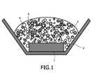
- FIG. 1A detailed construction of such a light-emitting device is shown in Fig. 1 .
- the device of Fig. 1comprises an LED 1 positioned in a reflector cup 2.
- a phosphor composition 4,5is positioned in the path of light emitted by LED 1.
- the phosphor compositionis embedded in a resin.
- the shape of reflector cup 2may be selected to provide a particular pattern of light emitted from the device, as is known in the art.
- the walls of reflector cup 2can be parabolic.
- the devicefurther comprises a polymer for encapsulating the phosphor or phosphor blend.
- the phosphor or phosphor blendshould exhibit high stability properties in the encapsulant.
- the polymeris optically clear to prevent significant light scattering.
- the polymeris selected from the group consisting of epoxy and silicone resins.
- a variety of polymersare known in the LED industry for making LED lamps. Adding the phosphor mixture to a liquid that is a polymer precursor can perform encapsulation.
- the phosphor mixturecan be a powder. Introducing phosphor particles into polymer precursor liquid results in formation of a slurry (i.e. a suspension of particles). Upon polymerization, the phosphor mixture is fixed rigidly in place by the encapsulation.
- both the composition and the LEDare encapsulated in the polymer.
- the phosphorsare applied either separately or in a mixture.
- the phosphorscompletely or partially absorb the light from the LED and emit it again in other spectral regions (primarily yellow and green) in a sufficiently broad band (specifically with a significant proportion of red) that an overall emission with the desired color point is formed.
- the wavelength of the LEDis tuned to the particular phosphors in the blend such that each of the phosphors in the blend is excited by emission from the LED.
- a phosphor blend using wide band phosphors according to embodiments of the inventionmay have a relatively high color rendering index, as high as 91-93.
- the phosphor blendmay also include a phosphor that emits blue light.
- the color points corresponding to a black body at various temperaturesare given by the black body locus (BBL). Because the color emitted from a black body is considered to be white, and white light is generally desirable for a lamp, it is generally desirable that color point of the light emitted from the luminescent material of a luminescent lamp fall on or near the BBL.
- a portion of the BBL shown in Fig. 2Aincludes three color temperature points highlighted on the BBL corresponding to white light emitting LEDs, whose emission spectra are given in Fig. 4A .
- a portion of the BBL shown in Fig. 2Bincludes three color temperature points highlighted on the BBL corresponding to white light emitting LEDs, whose emission spectra are given in Fig. 4B .
- a CRI of 100is an indication that the light emitted from the light source is similar to that from a black body source, i.e. an incandescent or halogen lamp.
- a CRI of 85 to 95can be attained by applying a phosphor mixture comprising Lu 3 Al 5 O 12 :Ce and CaS:Eu to a blue-emitting LED.
- Figs. 2A and 2Bshow the color coordinates of a range of illumination systems providing white light that can be produced from various combinations of blue LEDs and a cerium-activated lutetium-aluminum-garnet phosphor and CaS:Eu or Sr 2 Si 5 N 8 :Eu of the present invention.
- More than one phosphor according to embodiments of the present inventionmay be incorporated in the same device to provide for color adjustment.
- the green-emitting phosphormay be combined when appropriate, with a further yellow or red-emitting phosphor for the production of specific colored light and more preferably for production of white light with a high color-rendering index of greater than 80.
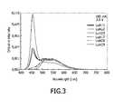
- a green emissioncan be generated which is shown in some examples in Fig. 3 .
- the amount of phosphor disposed on the deviceincreases, eventually all of the emission from the LED is absorbed, such that only emission from the phosphor remains. Devices with such heavy phosphor loading may be used in applications requiring green light.
- the garnet phosphors described aboveemit a broad band in the yellow-green spectral range of the visible spectrum with very high intensity under both UV and blue excitations and thus can provide the green component in LEDs emitting specific colors or white light. Total conversion efficiency can be up to 90%. Additional important characteristics of the phosphors include 1) resistance to thermal quenching of luminescence at typical device operating temperatures (e.g. 80°C); 2) lack of interfering reactivity with the encapsulating resins used in the device fabrication; 3) suitable absorptive profiles to minimize dead absorption within the visible spectrum; 4) a temporally stable luminous output over the operating lifetime of the device and; 5) compositionally controlled tuning of the phosphors excitation and emission properties. Fig.
- Sr 2 Si 5 N 8 :Eu 2+is preferred as a red phosphor as it exhibits similar performance at high temperatures, as illustrated in Fig. 9 , which illustrates the relative intensity of Sr 2 Si 5 N 8 :Eu 2+ as a function of temperature.
- the Sr 2 Si 5 N 8 :Eu 2+ emission intensityis 90% room temperature intensity.
- Lutetium-containing garnet phosphors included with other phosphors in devices designed to emit white lightmay offer improved color rendering over garnet phosphors that do not include lutetium, such as Y 3 Al 5 O 12 :Ce 3+ .
- the improved color renderingis due to the smaller Stokes' shift of Lu 3 Al 5 O 12 :Ce 3+ relative to Y 3 Al 5 O 12 :Ce 3+ .
- Phosphorssuch as Lu 3 Al 5 O 12 :Ce 3+ and Y 3 Al 5 O 12 :Ce 3+ absorb an excitation energy typically in the form of radiation, store the energy, then emit the stored energy as radiation of a different energy.
- Fig. 10illustrates the smaller Stokes' shift of Lu 3 Al 5 O 12 :Ce 3+ as demonstrated by excitation and emission spectra of Lu 3 Al 5 O 12 :Ce 3+ and Y 3 Al 5 O 12 :Ce 3+ .
- the excitation spectra of both phosphorsare very similar, the peak emission from Lu 3 Al 5 O 12 :Ce 3+ (curve 20) occurs at a wavelength about 40 nm shorter than the peak emission from Y 3 Al 5 O 12 :Ce 3+ (curve 22).
- the smaller Stokes' shift of Lu 3 Al 5 O 12 :Ce 3+eliminates a gap in the spectrum of combined pump emission and phosphor emission at long blue wavelengths and short green wavelengths, resulting in better color rendering.
- a red-emitting phosphoris mixed with a lutetium-containing garnet phosphor, such as the device illustrated in Fig. 1 , it may be difficult to exploit the small Stokes' shift of the lutetium-containing garnet phosphor since the red-emitting phosphor may absorb a significant portion of the light emitted by the lutetium-containing garnet phosphor. Lutetium-containing garnet phosphors tend to be very dense.
- 11-14illustrate embodiments of the device where the red-emitting phosphor and lutetium-containing garnet phosphor are deposited such that absorption by the red-emitting phosphor of light emitted by the lutetium-containing garnet phosphor is minimized.
- the lutetium-containing garnet phosphor 5is mixed with a resin or other transparent material and disposed on one side of reflector cup 2, while any other phosphors 4 are mixed separately with a resin or other transparent material and disposed on the other side of reflector cup 2, such that slurry 5 does not appreciably mix with slurry 4.
- the viscosity of the transparent material forming the slurryis selected to avoid mixing phosphor 4 with phosphor 5.
- lutetium-containing garnet phosphor 5 and any other phosphors 4are adjacent to each other, rather than mixed in the same slurry, light emitted by lutetium-containing garnet phosphor 5 is less likely to be absorbed by any red-emitting phosphors in slurry 4.
- the lutetium-containing garnet phosphor 5 and other phosphors 4are deposited over LED 1 as discrete layers.
- Phosphor layer 4including any red-emitting phosphors, is deposited closest to LED 1.
- Lutetium-containing garnet phosphor 5is then deposited over phosphor layer 4.
- Phosphor layers 4 and 5may be separated by an optional transparent layer 6.
- Phosphor layers 4 and 5may be deposited as slurries in a resin or other transparent material; deposited as thin films by, for example, electron beam evaporation, thermal evaporation, rf-sputtering, chemical vapor deposition, or atomic layer epitaxy; or deposited as conformal layers over LED 1 by, for example, screen printing, stenciling as described in U.S. Patent 6,650,044 , or by electrophoretic deposition as described in U.S. Patent 6,576,488 . Thin films are described in more detail in U.S. Patent 6,696,703 . Each of U.S. Patent 6,696,703 , U.S. Patent 6,650,044 and U.S.
- Patent 6,576,488are incorporated herein by reference.
- the phosphor in a conformal layergenerally behaves as multiple phosphor particles.
- a thin filmtypically contains no materials other than phosphor.
- a conformal layeroften includes materials other than phosphor, such as, for example, silica.
- the lutetium-containing garnet phosphor 5 and other phosphors 4are deposited on LED 1 in a plurality of small regions.
- the different regionsmay form a pattern, such as a checkerboard pattern. If light from LED 1 is to escape unconverted, as in the case where blue light emitted by the LED mixes with green and red light emitted by phosphors to make white light, the amount of unconverted light may be controlled by controlling the thickness of phosphor regions 4 and 5, or by leaving regions of LED 1 uncovered, or covered by an optional transparent material 7 that does not convert the light emitted by LED 1. Patterns of different phosphor layers as illustrated in Fig.
- a first layer of phosphor by electrophoretic depositionmay be formed by depositing a first layer of phosphor by electrophoretic deposition, patterning that layer using conventional lithography and etching techniques, then depositing a second phosphor layer by electrophoretic deposition.
- patterns of phosphor layersmay be deposited by screen printing or ink jet printing.
- a pattern of phosphor layersmay be formed by pipetting the individual phosphor mixes 4 and 5 into wells in a clear plastic microplate used for microbiology. The phosphor-filled microplate is then placed on LED 1. Phosphor-filled microplates may be formed separately from LED 1.
- a plurality of small regions of phosphor 4which includes any red-emitting phosphors, is formed on the surface of LED 1.
- a layer of lutetium-containing garnet phosphor 5is then deposited over the plurality of regions of phosphor 4.
- Each of the embodiments illustrated in Figs. 11-14avoid the problem of light being absorbed and reemitted by the lutetium-containing garnet phosphor prior to being incident on a red-emitting phosphor.
- light emitted by LED 1is incident on the red-emitting phosphor first, or is incident on the red-emitting phosphor and the lutetium-containing garnet phosphor in separate regions.
- the arrangements illustrated in Figs. 11-14thus reduce the probability of light emitted from the lutetium-containing garnet phosphor being absorbed by a red-emitting phosphor.
- Lutetium-containing garnet phosphors according to the present inventionare easily synthesized, as illustrated in the following example:
- one or more of the starting materialsmay be oxygen-containing compounds such as oxides, nitrates, sulfates, acetates, citrates, or chlorates, which are soluble in a nitric acid solution.
- nitric acid solutionamounts of Lu 2 O 3 , Al(NO 3 ) 3 ⁇ 9H 2 O, Ce(NO 3 ) 3 ⁇ 6H 2 O and AlF 3 are blended and dissolved in a nitric acid solution.
- the strength of the acid solutionis chosen to rapidly dissolve the oxygen-containing compounds and the choice is within the skill of a person skilled in the art.
- the nitric acid solutionis evaporated.
- the dried precipitateis ball milled or otherwise thoroughly blended and then calcined in a CO-atmosphere at about 1300°C for a sufficient time to ensure a substantially complete dehydration of the starting material.
- the calcinationmay be carried out at a constant temperature.
- the calcinations temperaturemay be ramped from ambient to and held at the final temperature for the duration of the calcination.
- the calcined materialis similarly fired at 1500-1700°C under a reducing atmosphere such as H 2 , CO, or a mixture of one of these gases with an inert gas.
- the calcined materialis fired for a sufficient time for the decomposition of the oxygen-containing compounds to convert all of the calcined material to the desired phosphor composition.
- the resulting powderis milled on a roller bench for several hours.
- the milled powderhas an average particle size of 40 to 60 ⁇ m. Its quantum efficiency is 90 % and its lumen equivalent is between 430 and 470 1m/W.
- the table belowgives the wavelength and color point of several suitable phosphor compounds.
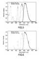
- Figs. 5, 6 , and 7illustrate the emission spectra of some of the compounds in the above table. When excited with radiation of wavelength 355 nm, these garnet phosphors are found to give a broad band emission, which peaks at 515 nm.
- Fig. 5shows excitation and emission spectra for the composition (Lu o.99 Ce 0.01 ) 3 Al 5 O 12 .
- Fig. 6shows excitation and emission spectra for the composition (Lu 0.495 Y 0.494 Ce 0.01 ) 3 Al 5 O 12 .
- Fig, 7demonstrates that the excitation band of (Lu 0.989 Ce 0.010 Pr .001 ) 3 Al 5 O 12 , is a broad band (515 - 540 nm) with a peak extending from 515 - 540 nm and a side band at 610 nm.
- a phosphor blendcomprising at least one of the suitable red phosphors as claimed is suspended into a silicone precursor. A droplet of this suspension is deposited onto the LED chip and subsequently polymerized. A plastic lens seals the LED.
Landscapes
- Chemical & Material Sciences (AREA)
- Inorganic Chemistry (AREA)
- Engineering & Computer Science (AREA)
- Materials Engineering (AREA)
- Organic Chemistry (AREA)
- Luminescent Compositions (AREA)
- Led Device Packages (AREA)
- Led Devices (AREA)
- Non-Portable Lighting Devices Or Systems Thereof (AREA)
Description
- The present invention generally relates to an illumination system comprising a radiation source and a fluorescent material comprising a phosphor.
- Recently, various attempts have been made to make white light emitting illumination systems by using light emitting diodes (LEDs) as radiation sources. When generating white light with an arrangement of red, green and blue light emitting diodes, there has been such a problem that white light of the desired tone cannot be generated due to variations in the tone, luminance and other factors of the light emitting diodes.
- In order to solve these problems, there have been previously developed various illumination systems, which convert the color of light emitted by light emitting diodes, by means of a fluorescent material comprising a phosphor to provide a visible white light illumination.
- Previous illumination systems have been based in particular either on the trichromatic (RGB) approach, i.e. on mixing three colors, namely red, green and blue, in which case the latter component may be provided by a phosphor or by the primary emission of the LED or in a second, simplified solution, on the dichromatic (BY) approach, mixing yellow and blue colors, in which case the yellow component may be provided by a yellow phosphor and the blue component may be provided by the primary emission of blue LED.
- In particular, the dichromatic approach as disclosed in, for example,
U.S. Patent 5,998,925 uses a blue light emitting diode of InGaN semiconductor combined with a Y3Al5O12:Ce3+ (YAG-Ce3+) phosphor. The YAG-Ce3+ phosphor is coated on the InGaN LED, and a portion of the blue light emitted from the LED is converted to yellow light by the phosphor. Another portion of the blue light from the LED is transmitted through the phosphor. Thus, this system emits both blue light emitted from the LED, and yellow light emitted from the phosphor. The mixture of blue and yellow emission bands are perceived as white light by an observer with a CRI in the middle 80s and a color temperature, Tc, that ranges from about 6000 K to about 8000 K. - However, white light LEDs based on the dichromatic approach can only be used to a limited extent for general-purpose illumination, on account of their poor color rendering caused by the absence of red color components.
WO2004084261 describes an illumination system comprising a radiation source and a fluorescent material comprising at least one phosphor capable of absorbing a portion of the light emitted by the radiation source and emitting light of a wavelength different from that of the absorbed light; wherein said at least one phosphor is a green-emitting cerium-activated lutetium-aluminum-garnet of general formula (Lu1-x-y-a-bYxGdy)3(Al1-zGaz)5O12:CeaPrb wherein 0 < x < 1, 0 < y < 1, 0 < z ≤ 0.1, 0 < a ≤ 0.2 and 0 < b ≤ 0.1. The invention also relates to with a green-emitting cerium-activated lutetiumaluminum-garnet of general formula (Lu1-x-y-a-bYxGdy)3(Al1-zGaz)5O12:CeaPrb wherein 0 < x < 1, 0 < y < 1,0 < z ≤ 0.1, 0 < a ≤ 0.2 and 0 < b ≤ 0.1.US6351069 describes a light emitting device and a method of fabricating the device utilize a supplementary fluorescent material that radiates secondary light in the red spectral region of the visible light spectrum to increase the red color component of the composite output light. The secondary light from the supplementary fluorescent material allows the device to produce "white" output light that is well-balanced with respect to color for true color rendering applications. The supplementary fluorescent material is included in a fluorescent layer that is positioned between a die and a lens of the device. The die is preferably a GaN based die that emits light having a peak wavelength of 470 nm. The fluorescent layer also includes a main fluorescent material. Preferably, the main fluorescent material is Cerium (Ce) activated and Gadolinium (Gd) doped Yttrium Aluminum Garnet (YAG) phosphor ("Ce:YAG phosphor"). In a first preferred embodiment, the supplementary fluorescent material is a compound that is produced by doping the Ce:YAG phosphor with a trivalent ion of Praseodymium (Pr). In a second preferred embodiment, the supplementary fluorescent material is Europium (Eu) activated Strontium Sulphide (SrS) phosphor. The amount of supplementary phosphor in the fluorescent layer can vary depending on the amount of red color that may be required in the white output light. The exact amount of supplementary phosphor is not critical to the invention.WO0124284 - Wu et al, Mat. Res. Soc. Symp. Proc. Vol. 658 (2001), materials Research Society, GG118.1-GG11.8.6 describes spectral properties of various cerium doped garnet phosphors for application in white GaN-based LEDs.
- In accordance with embodiments of the invention, a system includes a radiation source capable of emitting first light and a fluorescent material capable of absorbing the first light and emitting second light having a different wavelength than the first light. The fluorescent material is a phosphor having the formula (Lu1-x-y-a-bYxGdy)3(Al1-zGaz)5O12:CeaPrb wherein 0 < x < 1, 0 < y < 1, 0 < z ≤ 0.1, 0 < a ≤ 0.2 and 0 < b ≤ 0.1. (Lu1-x-y-a-bYxGdy)3(Al1-zGaz)5O12:CeaPrb is combined with a second fluorescent material capable of emitting third light. The second fluorescent material may be a red-emitting phosphor, such that the combination of first, second, and third light emitted from the system appears white.
Fig. 1 shows a schematic view of a tri-color white LED lamp comprising a two- phosphor blend positioned in a pathway of light emitted by an LED structure.Fig. 2A (reference example) shows the coordinates of phosphor mixtures of (Lu0.495Y0.495Ce0.01)3Al5O12 and CaS in the chromaticity diagram of the Commission Internationals de I'Eclairage ("CIE").Fig. 2B (reference example) shows the coordinates of phosphor mixtures of Lu3Al5O12:Ce3+ and Sr2Si5N8:Eu in the CIE diagram. Blends of these phosphors may be produced to have coordinates close to the black body locus.Fig. 3 illustrates emission spectra of green LEDs upon excitation by a blue LED at 460 nm.Figs. 4A and 4B illustrates emission spectra of white LEDs.Fig. 5 (reference example) illustrates the excitation and emission spectra of (Lu0.99Ce0.01)3Al5O12.Fig. 6 (reference example) illustrates the excitation and emission spectra of (Lu0.989Ce0.01Pr0.001)3Al5O12.Fig. 7 (reference example) illustrates the excitation and emission spectra of (Lu0.495Y0.495Ce0.01)3Al5O12.Fig. 8 (reference example) illustrates the relative intensity of Lu3Al5O12:Ce3+ as a function of temperature.Fig. 9 illustrates the relative intensity of Sr2Si5N8:Eu2+ as a function of temperature.Fig. 10 (reference example) illustrates excitation and emission spectra of Lu3Al5O12:Ce3+ and Y3Al5O12:Ce3+.Figs. 11, 12, 13, and 14 illustrate embodiments of the invention including multiple phosphors.- Embodiments of the invention provide new phosphors that are excitable in the near UV-to-blue range and emit in the visible green range. The new phosphors are capable of absorbing a part of light emitted by a radiation source and emitting light of a wavelength different from the absorbed light.
- Embodiments of the present invention focus on a lutetium aluminum garnet as a phosphor in any configuration of an illumination system containing a radiation source, including, but not limited to discharge lamps, fluorescent lamps, LEDs, laser diodes and X-ray tubes. In some embodiments, the lutetium aluminum garnet phosphor is cerium-activated. As used herein, the term "radiation" encompasses radiation in the UV, IR and visible regions of the electromagnetic spectrum.
- While the use of the present phosphor is contemplated for a wide array of illumination, the present invention is described with particular reference to and finds particular application to light emitting diodes, especially UV- and blue-light-emitting diodes.
- The fluorescent material according to embodiments of the invention comprises as a phosphor a cerium-activated lutetium-aluminum-garnet compound. The phosphor conforms to the general formula (Lu1-x-y-a-bYxGdy)3(Al1-zGaz)5O12:CeaPrb wherein 0 < x < 1, 0 < y < 1,0 < z ≤ 0.1, 0 < a ≤ 0.2 and 0 < b ≤ 0.1.
- This class of phosphor material is based on activated luminescence of cubic garnet crystals. Garnets are a class of materials with the crystal chemical formula A3B5O12.
- A garnet crystal lattice has three different atomic occupying sites of dodecahedron octacoordination, octahedron hexacoordination and tetrahedron tetracoordination, in which the A cations are eight-coordinated with oxygens and the B cations are either octahedrally (six) or tetrahedrally (four) coordinated with oxygens. The crystal structure is cubic with 160 ions per unit cell containing eight formula units. In embodiments of the present invention, the A cations are lutetium ions alone or in combination with Yttrium and Gadolinium, in combinations and with activator substitutions of cerium and possibly praseodymium. The B cations may be aluminum and may be gallium or other ions, again, alone, in combinations and/or with substitutions. In particular, it was found that with activator ions substituted in the eight-coordinated or six-coordinated sites, these garnets are luminescent in response to x-ray stimulation. A particularly important activator ion, which is x-ray luminescent in this host material, is the Ce3+ ion located in eight-coordinated sites.
- Replacing some of the lutetium in a cerium activated lutetium aluminum garnet, Lu3Al5O12:Ce phosphor with a smaller ion such as gadolinium Gd3+ or yttrium Y3+ causes a shift in the phosphor's emission band from green to the yellow range.
- Replacing some of the aluminum in a cerium activated lutetium aluminum garnet, Lu3Al5O12:Ce phosphor with a larger ion such as gallium Ga3+ causes a shift in the phosphor's emission band from green to the blue range.
- Replacing some of the cerium in a cerium-activated lutetium-aluminum-garnet by praseodymium as a co-activator has the effect that the praseodymium produces secondary emission that is concentrated in the red region of the visible spectrum, instead of a typical broadband secondary emission from cerium-activated lutetium-aluminum-phosphor that is generally centered in the yellow region of the visible spectrum. The amount of praseodymium as a co-activator can vary, depending on the amount of red color that may be required in the white output light for a particular application. Compositions having praseodymium as an activator cation present at low concentrations may be particularly desirable since such compositions show a sharp line emission in the red region of the visible spectrum.
- The lutetium concentration influences the color locus of the emission light when used in a light source, in particular an LED. The color locus of this phosphor can be additionally fine-tuned using the ratio of the two concentrations Lu:Ce, which simplifies or optimizes adaptation to any further (yellow or red) phosphors in the LED. As the concentration of Ce in the phosphor increases, the blue-end of the emission spectrum of the phosphor shifts to longer wavelengths. In some embodiments, the phosphor contains about 1 to about 1.5 mole-percent Ce.
- Preferably these garnet phosphors may be coated with a thin, uniform layer of one or more compounds selected from the group formed by the fluorides and orthophosphates of the elements aluminum, scandium, yttrium, lanthanum gadolinium and lutetium, the oxides of aluminum, yttrium and lanthanum and the nitride of aluminum.
- The layer thickness customarily ranges from 0.001 to 0.2 µm and, thus, is so thin that it can be penetrated by the radiation of the radiation source without substantial loss of energy. The coatings of these materials on the phosphor particles can be applied, for example, by deposition from the gas phase or a wet-coating process.
- The phosphors according to the invention are responsive to ultraviolet light as in fluorescent lamps and light emitting diodes, visible light as in blue-emitting diodes, electrons (as in cathode ray tubes) and x-rays (as in radiography).
- The invention also concerns an illumination system comprising a radiation source and a fluorescent material comprising at least one phosphor of general formula (Lu1-x-y-a-bYxGdy)3(Al1-zGaz)5O12:CeaPrb wherein 0 < x < 1, 0 < y < 1, 0 <z ≤ 0.1, 0 < a ≤ 0.2 and 0 < b ≤ 0.1.
- Radiation sources include semiconductor optical radiation emitters and other devices that emit optical radiation in response to electrical excitation. Semiconductor optical radiation emitters include light emitting diode LED chips, light emitting polymers (LEPs), organic light emitting devices (OLEDs), polymer light emitting devices (PLEDs), etc.
- Moreover, light emitting components such as those found in discharge lamps and fluorescent lamps, such as mercury low and high pressure discharge lamps, sulfur discharge lamps, and discharge lamps based an molecular radiators are also contemplated for use as radiation sources with the present inventive phosphor compositions.
- In a preferred embodiment of the invention the radiation source is a light-emitting diode. Any configuration of an illumination system which includes a LED and a cerium- activated lutetium-aluminum garnet phosphor composition is contemplated in the present invention, preferably with addition of other well-known phosphors, which can be combined to achieve a specific color or white light of high efficiency and/or high color rendering index ("CRI") at a required color temperature, when irradiated by a LED emitting primary UV or blue light as specified above. White-emitting devices according to embodiments of the present invention are based on the combination of blue, red, and green colors. In some embodiments, the yellow to green and the red phosphors are so broad-banded that they have a sufficient proportion of emission throughout the whole spectral region.
- In a preferred embodiment of the invention the primary radiation source used is the radiation from a UV-emitting or blue-emitting LED-chip. Particularly good results are achieved with a blue LED whose emission maximum lies at 400 to 480 nm. Optimal ranges have been found to lie at 445 to 460 nm and 438 to 456 nm, taking particular account of the excitation spectrum of the garnet phosphors described above.
- Desirable white light lamp characteristics for general purposes are high brightness and high color rendering at economical cost. Improved efficiency and much improved color rendering ability is possible with the trichromatic lamp spectrum according to the RGB-approach having three emission bands: red at 590 to 630, green at 520 to 560 and blue at 450 nm. These wavelengths are near peaks in the CIE tristimulus functions, which are used to define colors.
- In some embodiments, particularly good color rendering is achieved by the joint use of two phosphors, namely a green emitting cerium-activated lutetium-aluminum-garnet phosphor of general formula (Lu1-x-y-a-bYxGdy)3(Al1-zGaz)5O12:CeaPrb wherein 0 < x < 1, 0 < y < 1, 0 < z ≤ 0.1, 0 < a ≤ 0.2 and 0 < b ≤ 0.1 together with a second phosphor. The second phosphor may be, for example, a red-emitting phosphor, such as a red emitting europium-activated phosphor selected from the group of (Ca1-xSrx)S:Eu wherein 0 < x ≤ 1 and (Sr1-x-yBaxCay)2-zSi5-aAlaN8-aOa:Euz wherein 0 ≤ a < 5, 0 < x ≤ 1, 0 ≤ y ≤ 1, and 0 z ≤ 1.
- Preferably a europium activated calcium strontium sulfide is used, which is a high chromaticity red phosphor excitable from the near UV (400 nm) to the blue-green (500 nm) with high quantum efficiency. For an optimized use of this phosphor for luminescent conversion of primary LED light it is necessary to modify the photophysical characteristics to achieve, for example, efficacy, color specifications and life time of related light emitting devices. The chromaticity and quantum efficiency of the europium activated strontium sulfide can be modified through the substitution of divalent metal ions for strontium from the list including Ba, Ca, Mg, and Zn. Suitable red phosphors are described in the following
table: Phosphor composition λmax [nm] Color point x, y SrS:Eu 610 0.627, 0.372 (Sr1-x-yBaxCay)2Si5N8:Eu 615 0.615,0.384 (Sr1-x-yBaxCay)2Si5-xAlxN8-xOx:Eu 615-650 Depends on x, y CaS:Eu 655 0.700, 0.303 (Sr1-xCax)S:Eu 610-655 Depends on x, y - The phosphor blend comprises a mixture of predetermined amounts and relative proportions of garnet-structured lutetium-aluminum oxide activated by cerium and calcium-strontium sulfide activated by divalent europium. The relative phosphor proportions are such that the composite emission of the first phosphor layer falls approximately within the warm-white ellipse as inscribed on the x-y chromaticity diagram of the ICI system.
- A white emitting radiation source comprising a InGaN chip, emitting in the blue range of the visible spectrum with a peak emission at 455 nm together with a phosphor blend comprising Lu3Al5O12:Ce and CaS:Eu with the corresponding spectral weight ratio blue:green:red = 1.1:2.4:2.18 emits white light with color coordinates x = 0.336 and y = 0.339 and index of color rendering of 83. The spectra of such white emitting devices comprising three different blends of Lu3Al5O12:Ce and CaS:Eu are given in
Fig. 4A . Fig. 4B illustrates spectra of three white devices including blends of Lu3Al5O12:Ce and Sr2Si5N8:Eu, excited by a blue LED at 450 nm.- A detailed construction of such a light-emitting device is shown in
Fig. 1 . The device ofFig. 1 comprises anLED 1 positioned in areflector cup 2. Aphosphor composition LED 1. The phosphor composition is embedded in a resin. The shape ofreflector cup 2 may be selected to provide a particular pattern of light emitted from the device, as is known in the art. For example, the walls ofreflector cup 2 can be parabolic. - In one embodiment, the device further comprises a polymer for encapsulating the phosphor or phosphor blend. In this embodiment, the phosphor or phosphor blend should exhibit high stability properties in the encapsulant. Preferably, the polymer is optically clear to prevent significant light scattering. In one embodiment, the polymer is selected from the group consisting of epoxy and silicone resins. A variety of polymers are known in the LED industry for making LED lamps. Adding the phosphor mixture to a liquid that is a polymer precursor can perform encapsulation. For example, the phosphor mixture can be a powder. Introducing phosphor particles into polymer precursor liquid results in formation of a slurry (i.e. a suspension of particles). Upon polymerization, the phosphor mixture is fixed rigidly in place by the encapsulation. In one embodiment, both the composition and the LED are encapsulated in the polymer.
- The phosphors are applied either separately or in a mixture. The phosphors completely or partially absorb the light from the LED and emit it again in other spectral regions (primarily yellow and green) in a sufficiently broad band (specifically with a significant proportion of red) that an overall emission with the desired color point is formed. The wavelength of the LED is tuned to the particular phosphors in the blend such that each of the phosphors in the blend is excited by emission from the LED. A phosphor blend using wide band phosphors according to embodiments of the invention may have a relatively high color rendering index, as high as 91-93. In the case of an LED emitting UV light, for example between about 330 nm and about 365 nm, in order to achieve high color rendering, in addition to yellow/green and red phosphors described above, the phosphor blend may also include a phosphor that emits blue light.
- The color points corresponding to a black body at various temperatures are given by the black body locus (BBL). Because the color emitted from a black body is considered to be white, and white light is generally desirable for a lamp, it is generally desirable that color point of the light emitted from the luminescent material of a luminescent lamp fall on or near the BBL. A portion of the BBL shown in
Fig. 2A includes three color temperature points highlighted on the BBL corresponding to white light emitting LEDs, whose emission spectra are given inFig. 4A . A portion of the BBL shown inFig. 2B includes three color temperature points highlighted on the BBL corresponding to white light emitting LEDs, whose emission spectra are given inFig. 4B . - Another figure of merit is the quality in rendering illuminated colors of a white light emitting radiation source, which is indicated as the color rendering index (CRI). A CRI of 100 is an indication that the light emitted from the light source is similar to that from a black body source, i.e. an incandescent or halogen lamp. A CRI of 85 to 95 can be attained by applying a phosphor mixture comprising Lu3Al5O12:Ce and CaS:Eu to a blue-emitting LED.
Figs. 2A and 2B show the color coordinates of a range of illumination systems providing white light that can be produced from various combinations of blue LEDs and a cerium-activated lutetium-aluminum-garnet phosphor and CaS:Eu or Sr2Si5N8:Eu of the present invention.- More than one phosphor according to embodiments of the present invention may be incorporated in the same device to provide for color adjustment.
- A green emitting illumination system with particularly good color rendering comprises the combination of a light emitting semiconductor component which emits primary light in the blue spectral range from 420 to 480 nm together with a phosphor blend containing a green emitting cerium-activated lutetium-aluminum garnet phosphor Lu3Al5O12:Ce, with the corresponding spectral weight ratio blue:green is chosen from 1.0:2.4 to 1.0:3.5 which emits green light with color coordinates x = 0.336 and y = 0.339, an index of color rendering of 83, and a lumen equivalent of about 450 lumen/Watt.
- The green-emitting phosphor may be combined when appropriate, with a further yellow or red-emitting phosphor for the production of specific colored light and more preferably for production of white light with a high color-rendering index of greater than 80.
- As a result of the green to yellow broad-band emission, a green emission can be generated which is shown in some examples in
Fig. 3 . As the amount of phosphor disposed on the device increases, eventually all of the emission from the LED is absorbed, such that only emission from the phosphor remains. Devices with such heavy phosphor loading may be used in applications requiring green light. - The garnet phosphors described above emit a broad band in the yellow-green spectral range of the visible spectrum with very high intensity under both UV and blue excitations and thus can provide the green component in LEDs emitting specific colors or white light. Total conversion efficiency can be up to 90%. Additional important characteristics of the phosphors include 1) resistance to thermal quenching of luminescence at typical device operating temperatures (e.g. 80°C); 2) lack of interfering reactivity with the encapsulating resins used in the device fabrication; 3) suitable absorptive profiles to minimize dead absorption within the visible spectrum; 4) a temporally stable luminous output over the operating lifetime of the device and; 5) compositionally controlled tuning of the phosphors excitation and emission properties.
Fig. 8 illustrates the relative intensity of Lu3Al5O12:Ce3+ as a function of temperature. The relative intensity is expressed as a percentage of the intensity at room temperature, 25°C. At 200°C, the Lu3Al5O12:Ce3+ emission intensity is 90% of room temperature intensity. At 300°C, the Lu3Al5O12:Ce3+ emission intensity is 70% of room temperature intensity. In embodiments requiring white light and operation at high temperature, Sr2Si5N8:Eu2+ is preferred as a red phosphor as it exhibits similar performance at high temperatures, as illustrated inFig. 9 , which illustrates the relative intensity of Sr2Si5N8:Eu2+ as a function of temperature. At 200°C, the Sr2Si5N8:Eu2+ emission intensity is 90% room temperature intensity. - Lutetium-containing garnet phosphors included with other phosphors in devices designed to emit white light may offer improved color rendering over garnet phosphors that do not include lutetium, such as Y3Al5O12:Ce3+. The improved color rendering is due to the smaller Stokes' shift of Lu3Al5O12:Ce3+ relative to Y3Al5O12:Ce3+. Phosphors such as Lu3Al5O12:Ce3+ and Y3Al5O12:Ce3+ absorb an excitation energy typically in the form of radiation, store the energy, then emit the stored energy as radiation of a different energy. When the emitted radiation has less quantum energy than the absorbed radiation, the wavelength of the emitted light increases over the absorbed light. This increase is referred to as the Stokes' shift.
Fig. 10 illustrates the smaller Stokes' shift of Lu3Al5O12:Ce3+ as demonstrated by excitation and emission spectra of Lu3Al5O12:Ce3+ and Y3Al5O12:Ce3+. Though the excitation spectra of both phosphors are very similar, the peak emission from Lu3Al5O12:Ce3+ (curve 20) occurs at a wavelength about 40 nm shorter than the peak emission from Y3Al5O12:Ce3+ (curve 22). When used in a white device, the smaller Stokes' shift of Lu3Al5O12:Ce3+ eliminates a gap in the spectrum of combined pump emission and phosphor emission at long blue wavelengths and short green wavelengths, resulting in better color rendering. - In a device where a red-emitting phosphor is mixed with a lutetium-containing garnet phosphor, such as the device illustrated in
Fig. 1 , it may be difficult to exploit the small Stokes' shift of the lutetium-containing garnet phosphor since the red-emitting phosphor may absorb a significant portion of the light emitted by the lutetium-containing garnet phosphor. Lutetium-containing garnet phosphors tend to be very dense. As a result, when a slurry containing such phosphors is deposited over a device, the lutetium-containing garnet phosphor particles tend to sink quickly, leaving most of the lutetium-containing garnet phosphor close to the device and most of the red-emitting phosphor further from the device. Light emitted by the lutetium-containing garnet phosphor thus has a high likelihood of striking a red-emitting phosphor particle and being absorbed.Figs. 11-14 illustrate embodiments of the device where the red-emitting phosphor and lutetium-containing garnet phosphor are deposited such that absorption by the red-emitting phosphor of light emitted by the lutetium-containing garnet phosphor is minimized. - In the device illustrated in
Fig. 11 , the lutetium-containinggarnet phosphor 5 is mixed with a resin or other transparent material and disposed on one side ofreflector cup 2, while anyother phosphors 4 are mixed separately with a resin or other transparent material and disposed on the other side ofreflector cup 2, such thatslurry 5 does not appreciably mix withslurry 4. In some embodiments, the viscosity of the transparent material forming the slurry is selected to avoid mixingphosphor 4 withphosphor 5. Since lutetium-containinggarnet phosphor 5 and anyother phosphors 4 are adjacent to each other, rather than mixed in the same slurry, light emitted by lutetium-containinggarnet phosphor 5 is less likely to be absorbed by any red-emitting phosphors inslurry 4. - In the device illustrated in
Fig. 12 , the lutetium-containinggarnet phosphor 5 andother phosphors 4 are deposited overLED 1 as discrete layers.Phosphor layer 4, including any red-emitting phosphors, is deposited closest toLED 1. Lutetium-containinggarnet phosphor 5 is then deposited overphosphor layer 4. Phosphor layers 4 and 5 may be separated by an optionaltransparent layer 6. Phosphor layers 4 and 5 may be deposited as slurries in a resin or other transparent material; deposited as thin films by, for example, electron beam evaporation, thermal evaporation, rf-sputtering, chemical vapor deposition, or atomic layer epitaxy; or deposited as conformal layers overLED 1 by, for example, screen printing, stenciling as described inU.S. Patent 6,650,044 , or by electrophoretic deposition as described inU.S. Patent 6,576,488 . Thin films are described in more detail inU.S. Patent 6,696,703 . Each ofU.S. Patent 6,696,703 ,U.S. Patent 6,650,044 andU.S. Patent 6,576,488 are incorporated herein by reference. In contrast to a thin film, which typically behaves as a single, large phosphor particle, the phosphor in a conformal layer generally behaves as multiple phosphor particles. In addition a thin film typically contains no materials other than phosphor. A conformal layer often includes materials other than phosphor, such as, for example, silica. - In the device illustrated in
Fig. 13 , the lutetium-containinggarnet phosphor 5 andother phosphors 4 are deposited onLED 1 in a plurality of small regions. The different regions may form a pattern, such as a checkerboard pattern. If light fromLED 1 is to escape unconverted, as in the case where blue light emitted by the LED mixes with green and red light emitted by phosphors to make white light, the amount of unconverted light may be controlled by controlling the thickness ofphosphor regions LED 1 uncovered, or covered by an optional transparent material 7 that does not convert the light emitted byLED 1. Patterns of different phosphor layers as illustrated inFig. 13 may be formed by depositing a first layer of phosphor by electrophoretic deposition, patterning that layer using conventional lithography and etching techniques, then depositing a second phosphor layer by electrophoretic deposition. Alternatively, patterns of phosphor layers may be deposited by screen printing or ink jet printing. In some embodiments, a pattern of phosphor layers may be formed by pipetting the individual phosphor mixes 4 and 5 into wells in a clear plastic microplate used for microbiology. The phosphor-filled microplate is then placed onLED 1. Phosphor-filled microplates may be formed separately fromLED 1. - In the device illustrated in
Fig. 14 , a plurality of small regions ofphosphor 4, which includes any red-emitting phosphors, is formed on the surface ofLED 1. A layer of lutetium-containinggarnet phosphor 5 is then deposited over the plurality of regions ofphosphor 4. - Each of the embodiments illustrated in
Figs. 11-14 avoid the problem of light being absorbed and reemitted by the lutetium-containing garnet phosphor prior to being incident on a red-emitting phosphor. In each case, light emitted byLED 1 is incident on the red-emitting phosphor first, or is incident on the red-emitting phosphor and the lutetium-containing garnet phosphor in separate regions. The arrangements illustrated inFigs. 11-14 thus reduce the probability of light emitted from the lutetium-containing garnet phosphor being absorbed by a red-emitting phosphor. - Lutetium-containing garnet phosphors according to the present invention are easily synthesized, as illustrated in the following example:
- For the phosphor synthesis of a phosphor of general formula (Lu1-x-y-a-bYxGdy)3(Ai1-zGaz)5O12:CeaPrb wherein 0 < x < 1, 0 < y < 1, 0 <z ≤ 0.1, 0 < a ≤ 0.2 and 0 < b ≤ 0.1, one or more of the starting materials may be oxygen-containing compounds such as oxides, nitrates, sulfates, acetates, citrates, or chlorates, which are soluble in a nitric acid solution. For example, amounts of Lu2O3, Al(NO3)3·9H2O, Ce(NO3)3·6H2O and AlF3 are blended and dissolved in a nitric acid solution. The strength of the acid solution is chosen to rapidly dissolve the oxygen-containing compounds and the choice is within the skill of a person skilled in the art. The nitric acid solution is evaporated. The dried precipitate is ball milled or otherwise thoroughly blended and then calcined in a CO-atmosphere at about 1300°C for a sufficient time to ensure a substantially complete dehydration of the starting material. The calcination may be carried out at a constant temperature. Alternatively, the calcinations temperature may be ramped from ambient to and held at the final temperature for the duration of the calcination. After an intermittent milling step the calcined material is similarly fired at 1500-1700°C under a reducing atmosphere such as H2, CO, or a mixture of one of these gases with an inert gas. The calcined material is fired for a sufficient time for the decomposition of the oxygen-containing compounds to convert all of the calcined material to the desired phosphor composition.
- The resulting powder is milled on a roller bench for several hours. The milled powder has an average particle size of 40 to 60 µm. Its quantum efficiency is 90 % and its lumen equivalent is between 430 and 470 1m/W. The color point is at x = 0.33 to 0.38, y = 0.57 to 0.58. The table below gives the wavelength and color point of several suitable phosphor compounds.
Phosphor composition λmax [nm] Color point x, y (Lu0.99Ce0.01)3Al5O12 515 + 540 0.339, 0.579 (Lu0.989Ce0.010Pr.001)3Al5O12 515 + 540 + 610 0.332, 0.574 (Lu0.495Y0.495Ce0.01)3Al5O12 525 + 550 0.377, 0.570 (Lu0.75Gd0.24Ce0.01)3Al5O12 520 + 545 0.350, 0.573 Figs. 5, 6 , and7 illustrate the emission spectra of some of the compounds in the above table. When excited with radiation of wavelength 355 nm, these garnet phosphors are found to give a broad band emission, which peaks at 515 nm.Fig. 5 shows excitation and emission spectra for the composition (Luo.99Ce0.01)3Al5O12.Fig. 6 shows excitation and emission spectra for the composition (Lu0.495Y0.494Ce0.01)3Al5O12.Fig, 7 demonstrates that the excitation band of (Lu0.989Ce0.010Pr.001)3Al5O12, is a broad band (515 - 540 nm) with a peak extending from 515 - 540 nm and a side band at 610 nm.- From the excitation spectra, it is also clear that these cerium-activated lutetium-aluminum garnet phosphors can be excited efficiently with radiation of wavelength 254 as well as 355 and 420 nm.
- For manufacturing a white illumination system based on a 460 nm emitting InGaN LED, a phosphor blend comprising at least one of the suitable red phosphors as claimed is suspended into a silicone precursor. A droplet of this suspension is deposited onto the LED chip and subsequently polymerized. A plastic lens seals the LED.
- Having described the invention in detail, those skilled in the art will appreciate that, given the present disclosure, modifications may be made to the invention without departing from the spirit of the inventive concept described herein. Therefore, it is not intended that the scope of the invention be limited to the specific embodiments illustrated and described.
Claims (21)
- A system comprising:a radiation source capable of emitting first light;a first fluorescent material capable of absorbing the first light and emitting second light having a different wavelength than the first light, wherein said fluorescent material comprises a phosphor having the formula (Lu1-x-y-a-bYxGdy)3(Al1-zGaz)5O12:CeaPrb wherein 0 < x < 1, 0 < y < 1, 0 <z ≤ 0.1, 0 < a ≤ 0.2 and 0 < b ≤ 0.1; anda second fluorescent material capable of emitting third light;wherein the first fluorescent material and the second fluorescent material are disposed over the radiation source as discrete layers.
- The system of claim 1 wherein the first light comprises light having a peak emission wavelength in the range of 400 to 480 nm.
- The system of claim 1 wherein the first light comprises light having a peak emission wavelength in the range of 438 to 456 nm.
- The system of claim 1 wherein the first light comprises light having a peak emission wavelength in the range of 330 to 365 nm.
- The system of claim 1 wherein the radiation source is a light emitting diode.
- The system of claim 1 wherein the second light is green light.
- The system of claim 1 wherein the third light comprises red light.
- The system of claim 1 wherein the second fluorescent material comprises an Eu(II)-activated phosphor.
- The system of claim 1 wherein the second fluorescent material comprises (Sr1-x-yBaxCay)2-zSi5-aAlaN8-aOa:Euz wherein 0 ≤ a < 5, 0 < x ≤ 1, 0 ≤ y ≤ 1, and 0 < z ≤ 1.
- The system of claim 1 wherein the second fluorescent material comprises Sr2Si5N8:Eu2+.
- The system of claim 1 wherein the second fluorescent material comprises (Sr1-xCax)S:Eu.
- The system of claim 1 wherein the second fluorescent material is closer to the radiation source than the first fluorescent material.
- The system of claim 1 further comprising a layer of transparent material disposed between the first fluorescent material and the second fluorescent material.
- The system of claim 1 wherein:the first fluorescent material is disposed over a first portion of the radiation source; andthe second fluorescent material is disposed over a second portion of the radiation source.
- The system of claim 1 wherein:the first fluorescent material is disposed over the radiation source in a plurality of first discrete regions; andthe second fluorescent material is disposed over the radiation source in a plurality of second discrete regions.
- The system of claim 15 wherein the plurality of first discrete regions and the plurality of second discrete regions form a pattern.
- The system of claim 15 further comprising a transparent material disposed over the radiation source in a plurality of third discrete regions.
- The system of claim 1 wherein:the second fluorescent material is disposed over the radiation source in a plurality of first discrete regions; andthe first fluorescent material is disposed over the second fluorescent material.
- The system of claim 1 further comprising a third fluorescent material capable of emitting fourth light.
- The system of claim 19 wherein the fourth light comprises blue light.
- The system of claim 1 wherein particles of the first fluorescent material are coated with a layer of one or more compounds selected from the group formed by the fluorides and orthophosphates of the elements aluminum, scandium, yttrium, lanthanum gadolinium and lutetium, the oxides of aluminum, yttrium and lanthanum and the nitride of aluminum.
Applications Claiming Priority (2)
| Application Number | Priority Date | Filing Date | Title |
|---|---|---|---|
| US785620 | 1985-10-09 | ||
| US10/785,620US7038370B2 (en) | 2003-03-17 | 2004-02-23 | Phosphor converted light emitting device |
Publications (3)
| Publication Number | Publication Date |
|---|---|
| EP1566426A2 EP1566426A2 (en) | 2005-08-24 |
| EP1566426A3 EP1566426A3 (en) | 2011-04-06 |
| EP1566426B1true EP1566426B1 (en) | 2015-12-02 |
Family
ID=34711904
Family Applications (1)
| Application Number | Title | Priority Date | Filing Date |
|---|---|---|---|
| EP05101220.1AExpired - LifetimeEP1566426B1 (en) | 2004-02-23 | 2005-02-18 | Phosphor converted light emitting device |
Country Status (3)
| Country | Link |
|---|---|
| EP (1) | EP1566426B1 (en) |
| JP (2) | JP4787521B2 (en) |
| TW (1) | TWI381044B (en) |
Families Citing this family (37)
| Publication number | Priority date | Publication date | Assignee | Title |
|---|---|---|---|---|
| US7671529B2 (en)* | 2004-12-10 | 2010-03-02 | Philips Lumileds Lighting Company, Llc | Phosphor converted light emitting device |
| US7648649B2 (en)* | 2005-02-02 | 2010-01-19 | Lumination Llc | Red line emitting phosphors for use in led applications |
| JP2009512178A (en)* | 2005-11-04 | 2009-03-19 | パナソニック株式会社 | LIGHT EMITTING MODULE AND DISPLAY DEVICE AND LIGHTING DEVICE USING THE SAME |
| JP2007173397A (en)* | 2005-12-20 | 2007-07-05 | Matsushita Electric Ind Co Ltd | LIGHT EMITTING MODULE AND DISPLAY DEVICE AND LIGHTING DEVICE USING THE SAME |
| US8264138B2 (en)* | 2006-01-20 | 2012-09-11 | Cree, Inc. | Shifting spectral content in solid state light emitters by spatially separating lumiphor films |
| US7775687B2 (en) | 2006-02-20 | 2010-08-17 | Nichia Corporation | Light emitting device |
| JP2007266583A (en)* | 2006-02-20 | 2007-10-11 | Nichia Chem Ind Ltd | Light emitting device |
| JP2008050493A (en)* | 2006-08-25 | 2008-03-06 | Mitsubishi Chemicals Corp | Phosphor and light emitting device using the same |
| US8529791B2 (en)* | 2006-10-20 | 2013-09-10 | Intematix Corporation | Green-emitting, garnet-based phosphors in general and backlighting applications |
| JP4953846B2 (en)* | 2007-02-06 | 2012-06-13 | スタンレー電気株式会社 | Light emitting device and manufacturing method thereof |
| JP2008308510A (en)* | 2007-06-12 | 2008-12-25 | Sony Corp | Light emission composition, optical apparatus using this, and display apparatus using this |
| US7905618B2 (en) | 2007-07-19 | 2011-03-15 | Samsung Led Co., Ltd. | Backlight unit |
| WO2009066206A1 (en)* | 2007-11-19 | 2009-05-28 | Koninklijke Philips Electronics N.V. | Light source and illumination system having a predefined external appearance |
| CN102017204A (en)* | 2008-05-07 | 2011-04-13 | 皇家飞利浦电子股份有限公司 | Illumination device with LED with a self-supporting grid containing luminescent material and method of making the self-supporting grid |
| DE102008051029A1 (en)* | 2008-10-13 | 2010-04-15 | Merck Patent Gmbh | Doped garnet phosphors with redshift for pcLEDs |
| CN101832518A (en) | 2009-03-11 | 2010-09-15 | 旭明光电股份有限公司 | Light emitting device of light emitting diode with composite phosphor layer |
| JP2010275426A (en)* | 2009-05-28 | 2010-12-09 | Sumitomo Chemical Co Ltd | Method for producing surface-treated phosphor particles and surface-treated phosphor particles |
| US8104908B2 (en) | 2010-03-04 | 2012-01-31 | Xicato, Inc. | Efficient LED-based illumination module with high color rendering index |
| US8273589B2 (en)* | 2010-03-19 | 2012-09-25 | Micron Technology, Inc. | Light emitting diodes and methods for manufacturing light emitting diodes |
| DE102010021341A1 (en)* | 2010-05-22 | 2011-11-24 | Merck Patent Gmbh | phosphors |
| KR101335522B1 (en) | 2012-02-29 | 2013-12-02 | 한국화학연구원 | Phosphors for blue-light excitation, a method for producing the same and white light emitting diode comprising the same |
| US9525110B2 (en)* | 2012-10-16 | 2016-12-20 | Denka Company Limited | Phosphor, light emitting device and lighting apparatus |
| WO2014097802A1 (en)* | 2012-12-21 | 2014-06-26 | 電気化学工業株式会社 | Fluorescent substance, light-emitting device, and illuminator |
| WO2014130051A1 (en)* | 2013-02-25 | 2014-08-28 | Empire Technology Development Llc | Hybrid nanoparticles and illumination devices using the hybrid nanopaticles |
| JP6326830B2 (en)* | 2013-02-28 | 2018-05-23 | 日亜化学工業株式会社 | Light emitting device and lighting device including the same |
| JP2014232826A (en)* | 2013-05-30 | 2014-12-11 | 亞徳光機股▲ふん▼有限公司 | Light emitting device |
| JP2015008061A (en) | 2013-06-25 | 2015-01-15 | 信越化学工業株式会社 | Exterior illumination |
| RU2549406C1 (en)* | 2013-09-26 | 2015-04-27 | Открытое акционерное общество "Институт пластмасс имени Г.С. Петрова" | Polymer luminescent composite for colourless light production, which is excited by blue light-emitting diode |
| DE102014010175A1 (en)* | 2014-07-09 | 2016-01-14 | Hydac Filtertechnik Gmbh | filter element |
| JP6471756B2 (en)* | 2014-12-09 | 2019-02-20 | 信越化学工業株式会社 | LED light source for in-vehicle headlights |
| WO2016150789A1 (en) | 2015-03-24 | 2016-09-29 | Koninklijke Philips N.V. | Blue emitting phosphor converted led with blue pigment |
| WO2016195080A1 (en)* | 2015-06-05 | 2016-12-08 | 国立大学法人九州大学 | Phosphorescent emissive material, method for causing emission of phosphorescence from phosphorescent emitter, method for manufacturing phosphorescent emissive material, organic light emissive element, and gas sensor |
| JP6288061B2 (en) | 2015-12-10 | 2018-03-07 | 日亜化学工業株式会社 | Method for manufacturing light emitting device |
| FR3083371B1 (en)* | 2018-06-28 | 2022-01-14 | Aledia | TRANSMITTER DEVICES, ASSOCIATED DISPLAY SCREEN AND METHODS OF MAKING A TRANSMITTER DEVICE |
| EP4045609A1 (en)* | 2019-10-14 | 2022-08-24 | Evonik Operations GmbH | Blue to uv up-converter comprising lanthanide ions such as pr3+ activated garnet and its application for surface disinfection purposes |
| EP3929253A1 (en)* | 2020-06-26 | 2021-12-29 | Evonik Operations GmbH | Composition for producing coatings with antimicrobial properties |
| CN118402317A (en) | 2021-12-17 | 2024-07-26 | 昕诺飞控股有限公司 | Light source with disinfection function |
Family Cites Families (16)
| Publication number | Priority date | Publication date | Assignee | Title |
|---|---|---|---|---|
| TW383508B (en) | 1996-07-29 | 2000-03-01 | Nichia Kagaku Kogyo Kk | Light emitting device and display |
| JP3486345B2 (en)* | 1998-07-14 | 2004-01-13 | 東芝電子エンジニアリング株式会社 | Semiconductor light emitting device |
| JP3645422B2 (en)* | 1998-07-14 | 2005-05-11 | 東芝電子エンジニアリング株式会社 | Light emitting device |
| US6351069B1 (en) | 1999-02-18 | 2002-02-26 | Lumileds Lighting, U.S., Llc | Red-deficiency-compensating phosphor LED |
| KR100683364B1 (en) | 1999-09-27 | 2007-02-15 | 필립스 루미리즈 라이팅 캄파니 엘엘씨 | Light Emitting Diodes Generate White Light by Complete Fluorescence Conversion |
| US6696703B2 (en) | 1999-09-27 | 2004-02-24 | Lumileds Lighting U.S., Llc | Thin film phosphor-converted light emitting diode device |
| EP1104799A1 (en)* | 1999-11-30 | 2001-06-06 | Patent-Treuhand-Gesellschaft für elektrische Glühlampen mbH | Red emitting luminescent material |
| JP2002042525A (en)* | 2000-07-26 | 2002-02-08 | Toyoda Gosei Co Ltd | Planar light source |
| EP1328959A1 (en)* | 2000-07-28 | 2003-07-23 | Osram Opto Semiconductors GmbH & Co. OHG | Luminescence conversion based light emitting diode and phosphors for wavelength conversion |
| US6650044B1 (en) | 2000-10-13 | 2003-11-18 | Lumileds Lighting U.S., Llc | Stenciling phosphor layers on light emitting diodes |
| DE10051242A1 (en)* | 2000-10-17 | 2002-04-25 | Philips Corp Intellectual Pty | Light-emitting device with coated phosphor |
| US6576488B2 (en) | 2001-06-11 | 2003-06-10 | Lumileds Lighting U.S., Llc | Using electrophoresis to produce a conformally coated phosphor-converted light emitting semiconductor |
| AU2003215785A1 (en)* | 2002-03-25 | 2003-10-08 | Philips Intellectual Property And Standards Gmbh | Tri-color white light led lamp |
| JP4991026B2 (en)* | 2003-02-26 | 2012-08-01 | 日亜化学工業株式会社 | Light emitting device |
| US7038370B2 (en) | 2003-03-17 | 2006-05-02 | Lumileds Lighting, U.S., Llc | Phosphor converted light emitting device |
| JP3871668B2 (en)* | 2003-08-26 | 2007-01-24 | 東芝電子エンジニアリング株式会社 | Semiconductor light emitting device |
- 2005
- 2005-02-18EPEP05101220.1Apatent/EP1566426B1/ennot_activeExpired - Lifetime
- 2005-02-21TWTW094105105Apatent/TWI381044B/ennot_activeIP Right Cessation
- 2005-02-23JPJP2005084754Apatent/JP4787521B2/ennot_activeExpired - Lifetime
- 2011
- 2011-03-08JPJP2011050587Apatent/JP5186016B2/ennot_activeExpired - Lifetime
Also Published As
| Publication number | Publication date |
|---|---|
| JP5186016B2 (en) | 2013-04-17 |
| EP1566426A3 (en) | 2011-04-06 |
| EP1566426A2 (en) | 2005-08-24 |
| JP2005303289A (en) | 2005-10-27 |
| TW200602475A (en) | 2006-01-16 |
| JP4787521B2 (en) | 2011-10-05 |
| JP2011119768A (en) | 2011-06-16 |
| TWI381044B (en) | 2013-01-01 |
Similar Documents
| Publication | Publication Date | Title |
|---|---|---|
| EP1566426B1 (en) | Phosphor converted light emitting device | |
| US7038370B2 (en) | Phosphor converted light emitting device | |
| EP1859657B1 (en) | Illumination system comprising a radiation source and a fluorescent material | |
| TWI443854B (en) | Illumination system comprising a yellow green-emitting luminescent material | |
| TWI407474B (en) | Ceramic luminescence converter and illumination system including the same | |
| EP1411558B1 (en) | Phosphor converted light emitting device | |
| US6685852B2 (en) | Phosphor blends for generating white light from near-UV/blue light-emitting devices | |
| US7015510B2 (en) | White light emitting phosphor blend for LED devices | |
| JP4418758B2 (en) | Irradiation system having a radiation source and a light emitter | |
| JP5216330B2 (en) | Illumination system including radiation source and luminescent material | |
| CN102939355B (en) | Oxycarbonitride phosphor and light emitting device using same | |
| US20040124758A1 (en) | Luminescene conversion based light emitting diode and phosphors for wave length conversion | |
| KR101072572B1 (en) | Red phosphor and its forming method for use in solid state lighting | |
| JP2006104413A (en) | Phosphor and white light emitting device using the same | |
| Jose | Mueller-Mach et a | |
| EP3313959B1 (en) | Phosphor compositions and lighting apparatus thereof | |
| KR20170096742A (en) | Oxy-nitride phosphor emitting red light and light emitting device package using same | |
| KR20160112162A (en) | Oxy-nitride phosphor and light emitting device package |
Legal Events
| Date | Code | Title | Description |
|---|---|---|---|
| PUAI | Public reference made under article 153(3) epc to a published international application that has entered the european phase | Free format text:ORIGINAL CODE: 0009012 | |
| AK | Designated contracting states | Kind code of ref document:A2 Designated state(s):AT BE BG CH CY CZ DE DK EE ES FI FR GB GR HU IE IS IT LI LT LU MC NL PL PT RO SE SI SK TR | |
| AX | Request for extension of the european patent | Extension state:AL BA HR LV MK YU | |
| RAP1 | Party data changed (applicant data changed or rights of an application transferred) | Owner name:PHILIPS LUMILEDS LIGHTING COMPANY LLC | |
| PUAL | Search report despatched | Free format text:ORIGINAL CODE: 0009013 | |
| AK | Designated contracting states | Kind code of ref document:A3 Designated state(s):AT BE BG CH CY CZ DE DK EE ES FI FR GB GR HU IE IS IT LI LT LU MC NL PL PT RO SE SI SK TR | |
| AX | Request for extension of the european patent | Extension state:AL BA HR LV MK YU | |
| 17P | Request for examination filed | Effective date:20111006 | |
| AKX | Designation fees paid | Designated state(s):AT BE BG CH CY CZ DE DK EE ES FI FR GB GR HU IE IS IT LI LT LU MC NL PL PT RO SE SI SK TR | |
| 17Q | First examination report despatched | Effective date:20120426 | |
| GRAP | Despatch of communication of intention to grant a patent | Free format text:ORIGINAL CODE: EPIDOSNIGR1 | |
| INTG | Intention to grant announced | Effective date:20150916 | |
| GRAS | Grant fee paid | Free format text:ORIGINAL CODE: EPIDOSNIGR3 | |
| GRAA | (expected) grant | Free format text:ORIGINAL CODE: 0009210 | |
| AK | Designated contracting states | Kind code of ref document:B1 Designated state(s):AT BE BG CH CY CZ DE DK EE ES FI FR GB GR HU IE IS IT LI LT LU MC NL PL PT RO SE SI SK TR | |
| REG | Reference to a national code | Ref country code:GB Ref legal event code:FG4D Ref country code:DE Ref legal event code:R081 Ref document number:602005047994 Country of ref document:DE Owner name:LUMILEDS HOLDING B.V., NL Free format text:FORMER OWNER: LUMILEDS LIGHTING U.S., LLC, SAN JOSE, CALIF., US | |
| REG | Reference to a national code | Ref country code:AT Ref legal event code:REF Ref document number:763621 Country of ref document:AT Kind code of ref document:T Effective date:20151215 Ref country code:CH Ref legal event code:EP | |
| REG | Reference to a national code | Ref country code:IE Ref legal event code:FG4D | |
| REG | Reference to a national code | Ref country code:DE Ref legal event code:R096 Ref document number:602005047994 Country of ref document:DE | |
| REG | Reference to a national code | Ref country code:FR Ref legal event code:PLFP Year of fee payment:12 | |
| REG | Reference to a national code | Ref country code:NL Ref legal event code:MP Effective date:20160302 | |
| REG | Reference to a national code | Ref country code:LT Ref legal event code:MG4D | |
| REG | Reference to a national code | Ref country code:AT Ref legal event code:MK05 Ref document number:763621 Country of ref document:AT Kind code of ref document:T Effective date:20151202 | |
| PG25 | Lapsed in a contracting state [announced via postgrant information from national office to epo] | Ref country code:LT Free format text:LAPSE BECAUSE OF FAILURE TO SUBMIT A TRANSLATION OF THE DESCRIPTION OR TO PAY THE FEE WITHIN THE PRESCRIBED TIME-LIMIT Effective date:20151202 Ref country code:ES Free format text:LAPSE BECAUSE OF FAILURE TO SUBMIT A TRANSLATION OF THE DESCRIPTION OR TO PAY THE FEE WITHIN THE PRESCRIBED TIME-LIMIT Effective date:20151202 | |
| PG25 | Lapsed in a contracting state [announced via postgrant information from national office to epo] | Ref country code:AT Free format text:LAPSE BECAUSE OF FAILURE TO SUBMIT A TRANSLATION OF THE DESCRIPTION OR TO PAY THE FEE WITHIN THE PRESCRIBED TIME-LIMIT Effective date:20151202 Ref country code:FI Free format text:LAPSE BECAUSE OF FAILURE TO SUBMIT A TRANSLATION OF THE DESCRIPTION OR TO PAY THE FEE WITHIN THE PRESCRIBED TIME-LIMIT Effective date:20151202 Ref country code:NL Free format text:LAPSE BECAUSE OF FAILURE TO SUBMIT A TRANSLATION OF THE DESCRIPTION OR TO PAY THE FEE WITHIN THE PRESCRIBED TIME-LIMIT Effective date:20151202 Ref country code:SE Free format text:LAPSE BECAUSE OF FAILURE TO SUBMIT A TRANSLATION OF THE DESCRIPTION OR TO PAY THE FEE WITHIN THE PRESCRIBED TIME-LIMIT Effective date:20151202 Ref country code:PL Free format text:LAPSE BECAUSE OF FAILURE TO SUBMIT A TRANSLATION OF THE DESCRIPTION OR TO PAY THE FEE WITHIN THE PRESCRIBED TIME-LIMIT Effective date:20151202 Ref country code:GR Free format text:LAPSE BECAUSE OF FAILURE TO SUBMIT A TRANSLATION OF THE DESCRIPTION OR TO PAY THE FEE WITHIN THE PRESCRIBED TIME-LIMIT Effective date:20160303 Ref country code:BE Free format text:LAPSE BECAUSE OF NON-PAYMENT OF DUE FEES Effective date:20160229 | |
| PG25 | Lapsed in a contracting state [announced via postgrant information from national office to epo] | Ref country code:IS Free format text:LAPSE BECAUSE OF FAILURE TO SUBMIT A TRANSLATION OF THE DESCRIPTION OR TO PAY THE FEE WITHIN THE PRESCRIBED TIME-LIMIT Effective date:20151202 | |
| PG25 | Lapsed in a contracting state [announced via postgrant information from national office to epo] | Ref country code:CZ Free format text:LAPSE BECAUSE OF FAILURE TO SUBMIT A TRANSLATION OF THE DESCRIPTION OR TO PAY THE FEE WITHIN THE PRESCRIBED TIME-LIMIT Effective date:20151202 Ref country code:IT Free format text:LAPSE BECAUSE OF FAILURE TO SUBMIT A TRANSLATION OF THE DESCRIPTION OR TO PAY THE FEE WITHIN THE PRESCRIBED TIME-LIMIT Effective date:20151202 | |
| PG25 | Lapsed in a contracting state [announced via postgrant information from national office to epo] | Ref country code:EE Free format text:LAPSE BECAUSE OF FAILURE TO SUBMIT A TRANSLATION OF THE DESCRIPTION OR TO PAY THE FEE WITHIN THE PRESCRIBED TIME-LIMIT Effective date:20151202 Ref country code:IS Free format text:LAPSE BECAUSE OF FAILURE TO SUBMIT A TRANSLATION OF THE DESCRIPTION OR TO PAY THE FEE WITHIN THE PRESCRIBED TIME-LIMIT Effective date:20160402 Ref country code:RO Free format text:LAPSE BECAUSE OF FAILURE TO SUBMIT A TRANSLATION OF THE DESCRIPTION OR TO PAY THE FEE WITHIN THE PRESCRIBED TIME-LIMIT Effective date:20151202 Ref country code:SK Free format text:LAPSE BECAUSE OF FAILURE TO SUBMIT A TRANSLATION OF THE DESCRIPTION OR TO PAY THE FEE WITHIN THE PRESCRIBED TIME-LIMIT Effective date:20151202 Ref country code:PT Free format text:LAPSE BECAUSE OF FAILURE TO SUBMIT A TRANSLATION OF THE DESCRIPTION OR TO PAY THE FEE WITHIN THE PRESCRIBED TIME-LIMIT Effective date:20160404 | |
| REG | Reference to a national code | Ref country code:DE Ref legal event code:R097 Ref document number:602005047994 Country of ref document:DE | |
| PG25 | Lapsed in a contracting state [announced via postgrant information from national office to epo] | Ref country code:MC Free format text:LAPSE BECAUSE OF FAILURE TO SUBMIT A TRANSLATION OF THE DESCRIPTION OR TO PAY THE FEE WITHIN THE PRESCRIBED TIME-LIMIT Effective date:20151202 Ref country code:LU Free format text:LAPSE BECAUSE OF FAILURE TO SUBMIT A TRANSLATION OF THE DESCRIPTION OR TO PAY THE FEE WITHIN THE PRESCRIBED TIME-LIMIT Effective date:20160218 | |
| REG | Reference to a national code | Ref country code:CH Ref legal event code:PL | |
| PLBE | No opposition filed within time limit | Free format text:ORIGINAL CODE: 0009261 | |
| STAA | Information on the status of an ep patent application or granted ep patent | Free format text:STATUS: NO OPPOSITION FILED WITHIN TIME LIMIT | |
| PG25 | Lapsed in a contracting state [announced via postgrant information from national office to epo] | Ref country code:DK Free format text:LAPSE BECAUSE OF FAILURE TO SUBMIT A TRANSLATION OF THE DESCRIPTION OR TO PAY THE FEE WITHIN THE PRESCRIBED TIME-LIMIT Effective date:20151202 Ref country code:LI Free format text:LAPSE BECAUSE OF NON-PAYMENT OF DUE FEES Effective date:20160229 Ref country code:CH Free format text:LAPSE BECAUSE OF NON-PAYMENT OF DUE FEES Effective date:20160229 | |
| 26N | No opposition filed | Effective date:20160905 | |
| PG25 | Lapsed in a contracting state [announced via postgrant information from national office to epo] | Ref country code:SI Free format text:LAPSE BECAUSE OF FAILURE TO SUBMIT A TRANSLATION OF THE DESCRIPTION OR TO PAY THE FEE WITHIN THE PRESCRIBED TIME-LIMIT Effective date:20151202 | |
| REG | Reference to a national code | Ref country code:IE Ref legal event code:MM4A | |
| PG25 | Lapsed in a contracting state [announced via postgrant information from national office to epo] | Ref country code:BE Free format text:LAPSE BECAUSE OF FAILURE TO SUBMIT A TRANSLATION OF THE DESCRIPTION OR TO PAY THE FEE WITHIN THE PRESCRIBED TIME-LIMIT Effective date:20151202 | |
| PG25 | Lapsed in a contracting state [announced via postgrant information from national office to epo] | Ref country code:IE Free format text:LAPSE BECAUSE OF NON-PAYMENT OF DUE FEES Effective date:20160218 | |
| REG | Reference to a national code | Ref country code:FR Ref legal event code:PLFP Year of fee payment:13 | |
| REG | Reference to a national code | Ref country code:DE Ref legal event code:R081 Ref document number:602005047994 Country of ref document:DE Owner name:LUMILEDS HOLDING B.V., NL Free format text:FORMER OWNER: PHILIPS LUMILEDS LIGHTING COMPANY, LLC, SAN JOSE, CALIF, US | |
| REG | Reference to a national code | Ref country code:FR Ref legal event code:PLFP Year of fee payment:14 | |
| PG25 | Lapsed in a contracting state [announced via postgrant information from national office to epo] | Ref country code:HU Free format text:LAPSE BECAUSE OF FAILURE TO SUBMIT A TRANSLATION OF THE DESCRIPTION OR TO PAY THE FEE WITHIN THE PRESCRIBED TIME-LIMIT; INVALID AB INITIO Effective date:20050218 Ref country code:CY Free format text:LAPSE BECAUSE OF FAILURE TO SUBMIT A TRANSLATION OF THE DESCRIPTION OR TO PAY THE FEE WITHIN THE PRESCRIBED TIME-LIMIT Effective date:20151202 | |
| PG25 | Lapsed in a contracting state [announced via postgrant information from national office to epo] | Ref country code:TR Free format text:LAPSE BECAUSE OF FAILURE TO SUBMIT A TRANSLATION OF THE DESCRIPTION OR TO PAY THE FEE WITHIN THE PRESCRIBED TIME-LIMIT Effective date:20151202 | |
| PG25 | Lapsed in a contracting state [announced via postgrant information from national office to epo] | Ref country code:BG Free format text:LAPSE BECAUSE OF FAILURE TO SUBMIT A TRANSLATION OF THE DESCRIPTION OR TO PAY THE FEE WITHIN THE PRESCRIBED TIME-LIMIT Effective date:20151202 | |
| REG | Reference to a national code | Ref country code:GB Ref legal event code:732E Free format text:REGISTERED BETWEEN 20180920 AND 20180926 | |
| P01 | Opt-out of the competence of the unified patent court (upc) registered | Effective date:20230530 | |
| PGFP | Annual fee paid to national office [announced via postgrant information from national office to epo] | Ref country code:DE Payment date:20240228 Year of fee payment:20 Ref country code:GB Payment date:20240220 Year of fee payment:20 | |
| PGFP | Annual fee paid to national office [announced via postgrant information from national office to epo] | Ref country code:FR Payment date:20240226 Year of fee payment:20 | |
| REG | Reference to a national code | Ref country code:DE Ref legal event code:R071 Ref document number:602005047994 Country of ref document:DE | |
| REG | Reference to a national code | Ref country code:GB Ref legal event code:PE20 Expiry date:20250217 | |
| PG25 | Lapsed in a contracting state [announced via postgrant information from national office to epo] | Ref country code:GB Free format text:LAPSE BECAUSE OF EXPIRATION OF PROTECTION Effective date:20250217 |